Pl a y r o om L i vi n g R oom Loung e Kitch en H al l wa y S tud y G ue s t R oo m Di n ing Room Infilled Timber/Blockwork 3220 3510 4525 11790 1090 Opening 2800 1534 Opening 6000 900 290 11210 290 290 4235 290 4235 Catnic CXL240 Extreme Loading Lintel - 3500mm Catnic CXL240 Extreme Loading Lintel - 3500mm Catnic CXL310 Extreme Loading Lintel Catnic CXL310 Extreme Loading Lintel Standard PCC Lintel or Catnic Box Lintel above internal openings Timber or Blockwork Standard Cavity Wall Infilled Timber/Blockwork 3200 Cantic Box Lintels 1510 1250 1 Proposed Sectional View 4126 863 2400 863 3266 640 2100 640 3381 Dr es s i n g R oom B e d r oo m B e d r oo m M a st e r B e d r oo m B e d r oo m E nsu ite Bat hro o m 2800 810 810 2500 100 1100 100 2500 3050 Ha l l w ay 95 1500 En s ui t e SCALE (@ A1) CHECKED BY TITLE PROJECT NUMBER CLIENT PROJECT DRAWING NUMBER REV DRAWN BY DATE STATUS PURPOSE OF ISSUE CODE SUITABILITY DESCRIPTION Please note: All drawings are for the purposes of planning only. Not for construction works. Report all discrepancies to the person named below, do not proceed without instruction. BRO take no responsibility should any drawing/s unless specified are used for building purposes. 1 : 50 7 Basset Close KT15 3AH BRO - 05032019 Two Storey Extensions Kene Igboebisi Client Proposed Floor Plans SH 5th March 19 North VISUAL SCALE 1:50 @ A1 5m 1m 4m 3m 2m 0m 1 : 50 PROPOSED GROUND FLOOR PLAN 1 Rev Description Date 1 : 50 PROPOSED FIRST FLOOR PLAN 2

Welcome message from author
This document is posted to help you gain knowledge. Please leave a comment to let me know what you think about it! Share it to your friends and learn new things together.
Transcript
Playroom
Living Room
Lounge
Kitchen
Hallway
Study
Guest Room
Dining Room
Infilled
Timber/Blockwork
3220
3510
4525
11790
1090 Opening 2800 1534 Opening 6000 900
290 11210 290
290
4235
290
4235
Cat
nic
CX
L2
40
Ext
rem
e
Lo
adin
g L
inte
l -3
50
0m
m
Cat
nic
CX
L2
40
Ext
rem
e
Lo
adin
g L
inte
l -3
50
0m
m
Catnic CXL310 Extreme Loading LintelCatnic CXL310 Extreme Loading Lintel
Standard PCC Lintel
or
Catnic Box Lintel
above internal openings
Timber
or
Blockwork
Standard
Cavity Wall
Infilled
Timber/Blockwork
3200
Cantic Box Lintels
1510
1250
1
Proposed Sectional View
4126
863 2400 863
3266
640 2100 640
3381
Dressing
Room
Bedroom
Bedroom
Master
Bedroom
Bedroom
Ensuite
Bathroom
2800
810
810
2500
100
1100
100 2500
3050
Hallway
95
1500
Ensuite
SCALE (@ A1)
CHECKED BY
TITLE
PROJECT NUMBER
CLIENT
PROJECT
DRAWING NUMBER REV
DRAWN BY DATE
STATUS PURPOSE OF ISSUE
CODE SUITABILITY DESCRIPTION
Please note:
All drawings are for the purposes of planning only.
Not for construction works.
Report all discrepancies to the personnamed below, do not proceed without instruction.
BRO take no responsibility should any
drawing/s unless specified are used for building purposes.
1 : 50
7 Basset CloseKT15 3AH
BRO - 05032019
Two Storey Extensions
Kene Igboebisi
Client
Proposed Floor Plans
SH 5th March 19
North
VISUAL SCALE 1:50 @ A1
5m1m 4m3m2m0m
1 : 50
PROPOSED GROUND FLOOR PLAN1
Rev Description Date
1 : 50
PROPOSED FIRST FLOOR PLAN2

600 10900 600
1000
600
470
530
600
SCALE (@ A1)
CHECKED BY
TITLE
PROJECT NUMBER
CLIENT
PROJECT
DRAWING NUMBER REV
DRAWN BY DATE
STATUS PURPOSE OF ISSUE
CODE SUITABILITY DESCRIPTION
Please note:
All drawings are for the purposes of planning only.
Not for construction works.
Report all discrepancies to the personnamed below, do not proceed without instruction.
BRO take no responsibility should any
drawing/s unless specified are used for building purposes.
1 : 20
7 Basset CloseKT15 3AH
BRO - 05032019
Two Storey Extensions
Kene Igboebisi
Client
Proposed Sectional View
SH 5th March 19
North
VISUAL SCALE 1:20 @ A1
2m0.4m 1.6m1.2m0.8m0m
Rev Description Date
1 : 20
SECTIONAL VIEW - REAR ELEVATION1
INTERMEDIATE FLOORSINTERMEDIATE FLOORSINTERMEDIATE FLOORSINTERMEDIATE FLOORS
Intermediate floor to be 25mm t&g flooring grade chipboard or floorboards laid on C24 joists at 400mm ctrs (see
engineer's calculation for sizes and details). Lay 100mm Rockwool mineral fibre quilt insulation min 10kg/m³ or
equivalent between floor joists. Ceiling to be 12.5 FireLine plasterboard with skim plaster set and finish. Joist
spans over 2.5m to be strutted at mid span using 38 x 38mm herringbone strutting or 38mm solid strutting (at
least 2/3 of joist depth). In areas such as kitchens, utility rooms and bathrooms, flooring to be moisture resistant
grade in accordance with BS EN 312:2010. Identification marking must be laid upper most to allow easy
identification. Provide lateral restraint where joists run parallel to walls, floors are to be strapped to walls with
1000mm x 30mm x 5mm galvanised mild steel straps or other approved in compliance with BS EN 845-1 at max
2.0m centres, straps to be taken across minimum 3 no. joists. Straps to be built into walls. Provide 38mm wide x ¾
depth solid noggins between joists at strap positions.
PITCHED ROOF INSULATION AT CEILING LEVELPITCHED ROOF INSULATION AT CEILING LEVELPITCHED ROOF INSULATION AT CEILING LEVELPITCHED ROOF INSULATION AT CEILING LEVEL
Pitch 22-45° (imposed load max 0.75 kN/m² - dead load max 0.75 kN/m²)
To achieve U value of 0.16 W/m²K
Timber roof structures to be designed by an Engineer in accordance with NHBC Technical Requirement
R5 Structural Design. Calculations to be based on BS EN 1995-1-1. Roofing tiles to match existing on 25
x 38mm tanalised sw treated battens on sarking felt supported on 47 x 150mm grade C24 rafters at max
400mm centres max span 3.47m. Rafters supported on 100 x 50mm sw wall plates. Insulation at ceiling
level to be 150mm XR4000 Celotex between ceiling joists with a further 25mm over joists.
Construct ceiling using sw joists at 400mm centres, finished internally with 12.5mm plasterboard and min
3mm thistle multi-finish plaster. Provide polythene vapour barrier between insulation and plasterboard.
Provide opening at eaves level at least equal to continuous strip 25mm wide in two opposite sides to
promote cross-ventilation. Mono pitched roofs to have ridge/high level ventilation equivalent to a 5mm
gap via proprietary tile vents spaced in accordance with manufacturer’s details.
Restraint strapping - 100mm x 50mm wall plate strapped down to walls. Ceiling joists and rafters to be
strapped to walls and gable walls, straps built into cavity, across at least 3 timbers with noggins. All straps
to be 1000 x 30 x 5mm galvanized straps or other approved to BSEN 845-1 at 2m centres.
THIS IS A GENERAL GUIDE BASED ON NORMAL LOADING CONDITIONS FOUND IN DOMESTIC
CONSTRUCTION. IT IS YOUR RESPONSIBILITY TO ASSESS YOUR DESIGN TO ASCERTAIN WHETHER
ENGINEER'S DETAILS/CALCULATIONS ARE REQUIRED. PLEASE REFER TO THE TRADA DOCUMENT –
'SPAN TABLES FOR SOLID TIMBER MEMBERS IN FLOORS, CEILINGS AND ROOFS FOR DWELLINGS'
OR ASK YOUR BUILDING CONTROL OFFICER FOR ADVICE.
STRIP FOUNDATIONSTRIP FOUNDATIONSTRIP FOUNDATIONSTRIP FOUNDATION
Provide 600mm x 600mm concrete foundation, concrete mix to conform to BS EN 206-1 and BS 8500-2. All foundations to be a minimum of 1000mm below ground level, exact depth to be agreed on site with Building
Control Officer to suit site conditions. All constructed in accordance with 2010 Building Regulations A1/2 and BS 8004:1986 Code of Practice for Foundations. Ensure foundations are constructed below invert level of any
adjacent drains. Base of foundations supporting internal walls to be min 600mm below ground level. Sulphate resistant cement to be used if required. Please note that should any adverse soil conditions be found or any major
tree roots in excavations, the Building Control Officer is to be contacted and the advice of a structural engineer should be sought.
SOLID FLOOR INSULATION OVER SLABSOLID FLOOR INSULATION OVER SLABSOLID FLOOR INSULATION OVER SLABSOLID FLOOR INSULATION OVER SLAB
To meet min U value required of 0.22 W/m²K
Solid ground floor to consist of 150mm consolidated well-rammed hardcore. Blinded with 50mm sand blinding. Provide
100mm ST2 or Gen2 ground bearing slab concrete mix to conform to BS 8500-2 over a 1200 gauge polythene DPM.
DPM to be lapped in with DPC in walls. Floor to be insulated over slab and DPM with min 75mm thick Celotex GA4000.
25mm insulation to continue around floor perimeters to avoid thermal bridging. A VCL should be laid over the
insulation boards and turned up 100mm at room perimeters behind the skirting, all joints to be lapped 150mm and
sealed. Finish with 65mm sand/cement finishing screed with light mesh reinforcement.
Where drain runs pass under new floor, provide A142 mesh 1.0m wide and min 50mm concrete cover over length of
drain.
Where existing suspended timber floor air bricks are covered by new extension, ensure cross-ventilation is maintained
by connecting to 100mm dia UPVC pipes with 100mm concrete cover laid under the extension. Pipes to terminate at
new 65mm x 215mm air bricks with cavity tray over.
BEAMSBEAMSBEAMSBEAMS
Supply and install new structural elements such as new beams, roof structure, floor
structure, bearings, and padstones in accordance with the Structural Engineer's
calculations and details. New steel beams to be encased in 12.5mm Gyproc FireLine
board with staggered joints, Gyproc FireCase or painted in Nullifire S or similar
intumescent paint to provide 1/2 hour fire resistance as agreed with Building
Control. All fire protection to be installed as detailed by specialist manufacturer.
WALLS BELOW GROUNDWALLS BELOW GROUNDWALLS BELOW GROUNDWALLS BELOW GROUND
All new walls to have Class A blockwork below ground level or alternatively
semi engineering brickwork in 1:4 masonry cement or equal approved
specification. Cavities below ground level to be filled with lean mix concrete min
225mm below damp proof course. Or provide lean mix backfill at base of cavity
wall (150mm below damp course) laid to fall to weepholes.

PROPOSEDGROUND FLOOR
PLAN
0
PROPOSED FIRSTFLOOR PLAN
2600
Ceiling Level
2400
Wall Plate Level
4700
Ridge Top Level
7400
Rear Ridge Level
6400
SCALE (@ A1)
CHECKED BY
TITLE
PROJECT NUMBER
CLIENT
PROJECT
DRAWING NUMBER REV
DRAWN BY DATE
STATUS PURPOSE OF ISSUE
CODE SUITABILITY DESCRIPTION
Please note:
All drawings are for the purposes of planning only.
Not for construction works.
Report all discrepancies to the personnamed below, do not proceed without instruction.
BRO take no responsibility should any
drawing/s unless specified are used for building purposes.
As indicated
7 Basset CloseKT15 3AH
BRO - 05032019
Two Storey Extensions
Kene Igboebisi
Client
Proposed Elevations
SH 5th March 19
North
VISUAL SCALE 1:50 @ A1
5m1m 4m3m2m0m
Rev Description Date
1 : 50
PROPOSED FRONT ELEVATION1
1 : 50
PROPOSED REAR ELEVATION2
1 : 100
PROPOSED LEFT ELEVATION3
1 : 100
PROPOSED RIGHT ELEVATION4
PLANNING NOTEPLANNING NOTEPLANNING NOTEPLANNING NOTE
Under new regulations that came into force on 1 October 2008 an extension or addition to a house is considered to be permitted development and not requiring an
application for planning permission, subject to the following limits and conditions:
-No more than half the area of land around the "original house" would be covered by additions to buildings.
-No extension forward of the principal elevation or side elevation fronting a highway.
-No extension higher than the highest part of the roof.
-Maximum depth of a single storey rear extension to be three metres for an attached house and four metres for a detached house.
-Maximum height of a single storey rear extension to be four metres.
-Maximum ridge and eaves height no higher than existing house.
-Roof pitch of extensions higher than one storey to match existing house
-Materials to be similar in appearance to the existing house.
-Upper-floor, side-facing windows to be obscure glazed: any opening to be 1.7m above the floor.

SCALE (@ A1)
CHECKED BY
TITLE
PROJECT NUMBER
CLIENT
PROJECT
DRAWING NUMBER REV
DRAWN BY DATE
STATUS PURPOSE OF ISSUE
CODE SUITABILITY DESCRIPTION
Please note:
All drawings are for the purposes of planning only.
Not for construction works.
Report all discrepancies to the personnamed below, do not proceed without instruction.
BRO take no responsibility should any
drawing/s unless specified are used for building purposes.
7 Basset CloseKT15 3AH
BRO - 05032019
Two Storey Extensions
Kene Igboebisi
Client
Proposed Additional Views
SH 5th March 19
North
VISUAL SCALE 1:50 @ A1
5m1m 4m3m2m0m
Rev Description Date

SCALE (@ A1)
CHECKED BY
TITLE
PROJECT NUMBER
CLIENT
PROJECT
DRAWING NUMBER REV
DRAWN BY DATE
STATUS PURPOSE OF ISSUE
CODE SUITABILITY DESCRIPTION
Please note:
All drawings are for the purposes of planning only.
Not for construction works.
Report all discrepancies to the personnamed below, do not proceed without instruction.
BRO take no responsibility should any
drawing/s unless specified are used for building purposes.
7 Basset CloseKT15 3AH
BRO - 05032019
Two Storey Extensions
Kene Igboebisi
Client
Proposed Expolded View
SH 5th March 19
North
VISUAL SCALE 1:50 @ A1
5m1m 4m3m2m0m
Rev Description Date
EXPOLDED VIEW1
SAFETY GLAZINGSAFETY GLAZINGSAFETY GLAZINGSAFETY GLAZING
All glazing in critical locations to be toughened or laminated safety glass to BS 6206, BS EN 14179 or BS EN
ISO 12543-1:2011 and Part K (Part N in Wales) of the current Building Regulations, i.e. within 1500mm
above floor level in doors and side panels within 300mm of door opening and within 800mm above floor level
in windows.
NEW AND REPLACEMENT WINDOWSNEW AND REPLACEMENT WINDOWSNEW AND REPLACEMENT WINDOWSNEW AND REPLACEMENT WINDOWS
New and replacement windows to be double glazed with 16mm argon gap and soft coat low-E glass. Window
Energy Rating to be Band C or better and to achieve U-value of 1.6 W/m²K. The door and window openings
should be limited to 25% of the extension floor area plus the area of any existing openings covered by the
extension.
NEW AND REPLACEMENT DOORSNEW AND REPLACEMENT DOORSNEW AND REPLACEMENT DOORSNEW AND REPLACEMENT DOORS
New and replacement doors to achieve a U-Value of
1.80W/m²K. Glazed areas to be double glazed with 16mm
argon gap and soft low-E glass. Glass to be toughened or
laminated safety glass to BS 6206, BS EN 14179 or BS EN
ISO 12543-1:2011 and Part K (Part N in Wales) of the
current Building Regulations.
LINTELSLINTELSLINTELSLINTELS
- For uniformly distributed loads and standard 2 storey domestic loadings only
Lintel widths are to be equal to wall thickness. All lintels over 750mm sized internal door openings to be 65mm deep
pre-stressed concrete plank lintels. 150mm deep lintels are to be used for 900mm sized internal door openings. Lintels
to have a minimum bearing of 150mm on each end. Any existing lintels carrying additional loads are to be exposed for
inspection at commencement of work on site. All pre-stressed concrete lintels to be designed and manufactured in
accordance with BS 8110, with a concrete strength of 50 or 40 N/mm² and incorporating steel strands to BS 5896 to
support loadings assessed to BS 5977 Part 1.
For other structural openings provide proprietary insulated steel lintels suitable for spans and loadings in compliance
with Approved Document A and lintel manufactures standard tables. Stop ends, DPC trays and weep holes to be
provided above all externally located lintels.
NEW AND REPLACEMENT DOORSNEW AND REPLACEMENT DOORSNEW AND REPLACEMENT DOORSNEW AND REPLACEMENT DOORS
New and replacement doors to achieve a U-Value of 1.80W/m²K. Glazed
areas to be double glazed with 16mm argon gap and soft low-E glass. Glass
to be toughened or laminated safety glass to BS 6206, BS EN 14179 or BS
EN ISO 12543-1:2011 and Part K (Part N in Wales) of the current Building
Regulations.
NEW AND REPLACEMENT DOORSNEW AND REPLACEMENT DOORSNEW AND REPLACEMENT DOORSNEW AND REPLACEMENT DOORS
New and replacement doors to achieve a U-Value of 1.80W/m²K.
Glazed areas to be double glazed with 16mm argon gap and soft
low-E glass. Glass to be toughened or laminated safety glass to BS
6206, BS EN 14179 or BS EN ISO 12543-1:2011 and Part K (Part
N in Wales) of the current Building Regulations.
NEW AND REPLACEMENT DOORSNEW AND REPLACEMENT DOORSNEW AND REPLACEMENT DOORSNEW AND REPLACEMENT DOORS
New and replacement doors to achieve a U-Value of
1.80W/m²K. Glazed areas to be double glazed with 16mm
argon gap and soft low-E glass. Glass to be toughened or
laminated safety glass to BS 6206, BS EN 14179 or BS EN
ISO 12543-1:2011 and Part K (Part N in Wales) of the
current Building Regulations.
EXTRACT TO KITCHENEXTRACT TO KITCHENEXTRACT TO KITCHENEXTRACT TO KITCHEN
Kitchen to have mechanical ventilation with an extract rating of
60l/sec or 30l/sec if adjacent to hob to external air, sealed to
prevent entry of moisture. Internal doors should be provided with a
10mm gap below the door to aid air circulation. Ventilation
provision in accordance with the Domestic Ventilation Compliance
Guide. Intermittent extract fans to BS EN 13141-4. Cooker hoods
to BS EN 13141-3. All fixed mechanical ventilation systems, where
they can be tested and adjusted, shall be commissioned and a
commissioning notice given to the Building Control Body.
STRAPPING FOR PITCHED ROOFSTRAPPING FOR PITCHED ROOFSTRAPPING FOR PITCHED ROOFSTRAPPING FOR PITCHED ROOF
Gable walls should be strapped to roofs at 2m centres. All external walls running
parallel to roof rafters to be restrained at roof level using 1000mm x 30mm x
5mm galvanised mild steel horizontal straps or other approved to BSEN 845-1
built into walls at max 2000mm centres and to be taken across minimum 3 rafters
and screw fixed. Provide solid noggins between rafters at strap positions. All wall
plates to be 100 x 50mm fixed to inner skin of cavity wall using 30mm x 5mm x
1000mm galvanized metal straps or other approved to BSEN 845-1 at maximum
2m centres.
RAINWATER DRAINAGERAINWATER DRAINAGERAINWATER DRAINAGERAINWATER DRAINAGE
New rainwater goods to be new 110mm UPVC half round gutters taken and connected into 68mm dia UPVC
downpipes. Rainwater taken to new soakaway, situated a min distance of 5.0m away from any building, via 110mm
dia UPVC pipes surrounded in 150mm granular fill. Soakaway to be min of 1 cubic metre capacity (or to depth to
Local Authorities approval) with suitable granular fill and with geotextile surround to prevent migration of fines. If
necessary carry out a porosity test to determine design and depth of soakaway.
MATERIALS AND WORKMANSHIPMATERIALS AND WORKMANSHIPMATERIALS AND WORKMANSHIPMATERIALS AND WORKMANSHIP
All works are to be carried out in a workmanlike manner. All
materials and workmanship must comply with Regulation 7 of
the Building Regulations, all relevant British Standards,
European Standards, Agreement Certificates, Product
Certification of Schemes (Kite Marks) etc. Products
conforming to a European technical standard or harmonised
European product should have a CE marking.
PITCHED ROOF VENTILATIONPITCHED ROOF VENTILATIONPITCHED ROOF VENTILATIONPITCHED ROOF VENTILATION
Maintain a 50mm air gap above insulation in the roof pitch to
ventilate roof. Provide opening at eaves level at least equal to
continuous strip 25mm wide and opening at ridge equal to
continuous strip 5mm wide to promote ventilation.
SCALE (@ A1)
CHECKED BY
TITLE
PROJECT NUMBER
CLIENT
PROJECT
DRAWING NUMBER REV
DRAWN BY DATE
STATUS PURPOSE OF ISSUE
CODE SUITABILITY DESCRIPTION
Please note:
All drawings are for the purposes of planning only.
Not for construction works.
Report all discrepancies to the personnamed below, do not proceed without instruction.
BRO take no responsibility should any
drawing/s unless specified are used for building purposes.
7 Basset CloseKT15 3AH
BRO - 05032019
Two Storey Extensions
Kene Igboebisi
Client
Proposed Building Reg Notes 1
SH 5th March 19
Rev Description Date
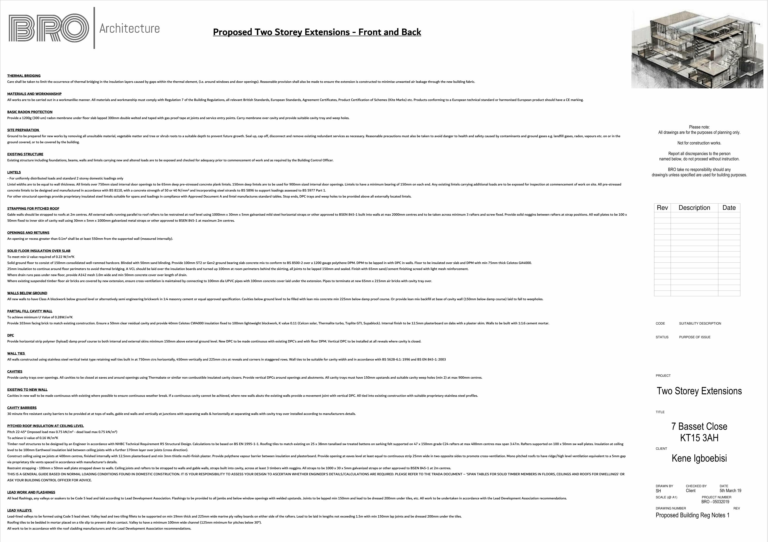
Proposed Two Storey Extensions Proposed Two Storey Extensions Proposed Two Storey Extensions Proposed Two Storey Extensions ---- Front and BackFront and BackFront and BackFront and Back
THERMAL BRIDGINGTHERMAL BRIDGINGTHERMAL BRIDGINGTHERMAL BRIDGING
Care shall be taken to limit the occurrence of thermal bridging in the insulation layers caused by gaps within the thermal element, (i.e. around windows and door openings). Reasonable provision shall also be made to ensure the extension is constructed to minimise unwanted air leakage through the new building fabric.
MATERIALS AND WORKMANSHIPMATERIALS AND WORKMANSHIPMATERIALS AND WORKMANSHIPMATERIALS AND WORKMANSHIP
All works are to be carried out in a workmanlike manner. All materials and workmanship must comply with Regulation 7 of the Building Regulations, all relevant British Standards, European Standards, Agreement Certificates, Product Certification of Schemes (Kite Marks) etc. Products conforming to a European technical standard or harmonised European product should have a CE marking.
BASIC RADON PROTECTIONBASIC RADON PROTECTIONBASIC RADON PROTECTIONBASIC RADON PROTECTION
Provide a 1200g (300 um) radon membrane under floor slab lapped 300mm double welted and taped with gas proof tape at joints and service entry points. Carry membrane over cavity and provide suitable cavity tray and weep holes.
SITE PREPARATION SITE PREPARATION SITE PREPARATION SITE PREPARATION
Ground to be prepared for new works by removing all unsuitable material, vegetable matter and tree or shrub roots to a suitable depth to prevent future growth. Seal up, cap off, disconnect and remove existing redundant services as necessary. Reasonable precautions must also be taken to avoid danger to health and safety caused by contaminants and ground gases e.g. landfill gases, radon, vapours etc. on or in the
ground covered, or to be covered by the building.
EXISTING STRUCTUREEXISTING STRUCTUREEXISTING STRUCTUREEXISTING STRUCTURE
Existing structure including foundations, beams, walls and lintels carrying new and altered loads are to be exposed and checked for adequacy prior to commencement of work and as required by the Building Control Officer.
LINTELSLINTELSLINTELSLINTELS
- For uniformly distributed loads and standard 2 storey domestic loadings only
Lintel widths are to be equal to wall thickness. All lintels over 750mm sized internal door openings to be 65mm deep pre-stressed concrete plank lintels. 150mm deep lintels are to be used for 900mm sized internal door openings. Lintels to have a minimum bearing of 150mm on each end. Any existing lintels carrying additional loads are to be exposed for inspection at commencement of work on site. All pre-stressed
concrete lintels to be designed and manufactured in accordance with BS 8110, with a concrete strength of 50 or 40 N/mm² and incorporating steel strands to BS 5896 to support loadings assessed to BS 5977 Part 1.
For other structural openings provide proprietary insulated steel lintels suitable for spans and loadings in compliance with Approved Document A and lintel manufactures standard tables. Stop ends, DPC trays and weep holes to be provided above all externally located lintels.
STRAPPING FOR PITCHED ROOFSTRAPPING FOR PITCHED ROOFSTRAPPING FOR PITCHED ROOFSTRAPPING FOR PITCHED ROOF
Gable walls should be strapped to roofs at 2m centres. All external walls running parallel to roof rafters to be restrained at roof level using 1000mm x 30mm x 5mm galvanised mild steel horizontal straps or other approved to BSEN 845-1 built into walls at max 2000mm centres and to be taken across minimum 3 rafters and screw fixed. Provide solid noggins between rafters at strap positions. All wall plates to be 100 x
50mm fixed to inner skin of cavity wall using 30mm x 5mm x 1000mm galvanized metal straps or other approved to BSEN 845-1 at maximum 2m centres.
OPENINGS AND RETURNSOPENINGS AND RETURNSOPENINGS AND RETURNSOPENINGS AND RETURNS
An opening or recess greater than 0.1m² shall be at least 550mm from the supported wall (measured internally).
SOLID FLOOR INSULATION OVER SLABSOLID FLOOR INSULATION OVER SLABSOLID FLOOR INSULATION OVER SLABSOLID FLOOR INSULATION OVER SLAB
To meet min U value required of 0.22 W/m²K
Solid ground floor to consist of 150mm consolidated well-rammed hardcore. Blinded with 50mm sand blinding. Provide 100mm ST2 or Gen2 ground bearing slab concrete mix to conform to BS 8500-2 over a 1200 gauge polythene DPM. DPM to be lapped in with DPC in walls. Floor to be insulated over slab and DPM with min 75mm thick Celotex GA4000.
25mm insulation to continue around floor perimeters to avoid thermal bridging. A VCL should be laid over the insulation boards and turned up 100mm at room perimeters behind the skirting, all joints to be lapped 150mm and sealed. Finish with 65mm sand/cement finishing screed with light mesh reinforcement.
Where drain runs pass under new floor, provide A142 mesh 1.0m wide and min 50mm concrete cover over length of drain.
Where existing suspended timber floor air bricks are covered by new extension, ensure cross-ventilation is maintained by connecting to 100mm dia UPVC pipes with 100mm concrete cover laid under the extension. Pipes to terminate at new 65mm x 215mm air bricks with cavity tray over.
WALLS BELOW GROUNDWALLS BELOW GROUNDWALLS BELOW GROUNDWALLS BELOW GROUND
All new walls to have Class A blockwork below ground level or alternatively semi engineering brickwork in 1:4 masonry cement or equal approved specification. Cavities below ground level to be filled with lean mix concrete min 225mm below damp proof course. Or provide lean mix backfill at base of cavity wall (150mm below damp course) laid to fall to weepholes.
PARTIAL FILL CAVITY WALLPARTIAL FILL CAVITY WALLPARTIAL FILL CAVITY WALLPARTIAL FILL CAVITY WALL
To achieve minimum U Value of 0.28W/m²K
Provide 103mm facing brick to match existing construction. Ensure a 50mm clear residual cavity and provide 40mm Celotex CW4000 insulation fixed to 100mm lightweight blockwork, K value 0.11 (Celcon solar, Thermalite turbo, Toplite GTI, Supablock). Internal finish to be 12.5mm plasterboard on dabs with a plaster skim. Walls to be built with 1:1:6 cement mortar.
DPCDPCDPCDPC
Provide horizontal strip polymer (hyload) damp proof course to both internal and external skins minimum 150mm above external ground level. New DPC to be made continuous with existing DPC’s and with floor DPM. Vertical DPC to be installed at all reveals where cavity is closed.
WALL TIES WALL TIES WALL TIES WALL TIES
All walls constructed using stainless steel vertical twist type retaining wall ties built in at 750mm ctrs horizontally, 450mm vertically and 225mm ctrs at reveals and corners in staggered rows. Wall ties to be suitable for cavity width and in accordance with BS 5628-6.1: 1996 and BS EN 845-1: 2003
CAVITIESCAVITIESCAVITIESCAVITIES
Provide cavity trays over openings. All cavities to be closed at eaves and around openings using Thermabate or similar non combustible insulated cavity closers. Provide vertical DPCs around openings and abutments. All cavity trays must have 150mm upstands and suitable cavity weep holes (min 2) at max 900mm centres.
EXISTING TO NEW WALLEXISTING TO NEW WALLEXISTING TO NEW WALLEXISTING TO NEW WALL
Cavities in new wall to be made continuous with existing where possible to ensure continuous weather break. If a continuous cavity cannot be achieved, where new walls abuts the existing walls provide a movement joint with vertical DPC. All tied into existing construction with suitable proprietary stainless steel profiles.
CAVITY BARRIERSCAVITY BARRIERSCAVITY BARRIERSCAVITY BARRIERS
30 minute fire resistant cavity barriers to be provided at at tops of walls, gable end walls and vertically at junctions with separating walls & horizontally at separating walls with cavity tray over installed according to manufacturers details.
PITCHED ROOF INSULATION AT CEILING LEVELPITCHED ROOF INSULATION AT CEILING LEVELPITCHED ROOF INSULATION AT CEILING LEVELPITCHED ROOF INSULATION AT CEILING LEVEL
Pitch 22-45° (imposed load max 0.75 kN/m² - dead load max 0.75 kN/m²)
To achieve U value of 0.16 W/m²K
Timber roof structures to be designed by an Engineer in accordance with NHBC Technical Requirement R5 Structural Design. Calculations to be based on BS EN 1995-1-1. Roofing tiles to match existing on 25 x 38mm tanalised sw treated battens on sarking felt supported on 47 x 150mm grade C24 rafters at max 400mm centres max span 3.47m. Rafters supported on 100 x 50mm sw wall plates. Insulation at ceiling
level to be 100mm Earthwool insulation laid between ceiling joists with a further 170mm layer over joists (cross direction).
Construct ceiling using sw joists at 400mm centres, finished internally with 12.5mm plasterboard and min 3mm thistle multi-finish plaster. Provide polythene vapour barrier between insulation and plasterboard. Provide opening at eaves level at least equal to continuous strip 25mm wide in two opposite sides to promote cross-ventilation. Mono pitched roofs to have ridge/high level ventilation equivalent to a 5mm gap
via proprietary tile vents spaced in accordance with manufacturer’s details.
Restraint strapping - 100mm x 50mm wall plate strapped down to walls. Ceiling joists and rafters to be strapped to walls and gable walls, straps built into cavity, across at least 3 timbers with noggins. All straps to be 1000 x 30 x 5mm galvanized straps or other approved to BSEN 845-1 at 2m centres.
THIS IS A GENERAL GUIDE BASED ON NORMAL LOADING CONDITIONS FOUND IN DOMESTIC CONSTRUCTION. IT IS YOUR RESPONSIBILITY TO ASSESS YOUR DESIGN TO ASCERTAIN WHETHER ENGINEER'S DETAILS/CALCULATIONS ARE REQUIRED. PLEASE REFER TO THE TRADA DOCUMENT – 'SPAN TABLES FOR SOLID TIMBER MEMBERS IN FLOORS, CEILINGS AND ROOFS FOR DWELLINGS' OR
ASK YOUR BUILDING CONTROL OFFICER FOR ADVICE.
LEAD WORK AND FLASHINGSLEAD WORK AND FLASHINGSLEAD WORK AND FLASHINGSLEAD WORK AND FLASHINGS
All lead flashings, any valleys or soakers to be Code 5 lead and laid according to Lead Development Association. Flashings to be provided to all jambs and below window openings with welded upstands. Joints to be lapped min 150mm and lead to be dressed 200mm under tiles, etc. All work to be undertaken in accordance with the Lead Development Association recommendations.
LEAD VALLEYS LEAD VALLEYS LEAD VALLEYS LEAD VALLEYS
Lead-lined valleys to be formed using Code 5 lead sheet. Valley lead and two tiling fillets to be supported on min 19mm thick and 225mm wide marine ply valley boards on either side of the rafters. Lead to be laid in lengths not exceeding 1.5m with min 150mm lap joints and be dressed 200mm under the tiles.
Roofing tiles to be bedded in mortar placed on a tile slip to prevent direct contact. Valley to have a minimum 100mm wide channel (125mm minimum for pitches below 30°).
All work to be in accordance with the roof cladding manufacturers and the Lead Development Association recommendations.

SCALE (@ A1)
CHECKED BY
TITLE
PROJECT NUMBER
CLIENT
PROJECT
DRAWING NUMBER REV
DRAWN BY DATE
STATUS PURPOSE OF ISSUE
CODE SUITABILITY DESCRIPTION
Please note:
All drawings are for the purposes of planning only.
Not for construction works.
Report all discrepancies to the personnamed below, do not proceed without instruction.
BRO take no responsibility should any
drawing/s unless specified are used for building purposes.
7 Basset CloseKT15 3AH
BRO - 05032019
Two Storey Extensions
Kene Igboebisi
Client
Proposed Building Reg Notes 2
SH 5th March 19
Rev Description Date
INTERNAL STUD PARTITIONSINTERNAL STUD PARTITIONSINTERNAL STUD PARTITIONSINTERNAL STUD PARTITIONS
100mm x 50mm softwood treated timbers studs at 400mm ctrs with 50 x 100mm head and sole plates and solid intermediate horizontal noggins at 1/3 height or 450mm. Provide min 10kg/m³ density acoustic soundproof quilt tightly
packed (eg. 100mm Rockwool or Isowool mineral fibre sound insulation) in all voids the full depth of the stud. Partitions built off doubled up joists where partitions run parallel or provide noggins where at right angles, or built off DPC on
thickened concrete slab if solid ground floor. Walls faced throughout with 12.5mm plaster board with skim plaster finish. Taped and jointed complete with beads and stops.
INTERNAL MASONRY PARTITIONSINTERNAL MASONRY PARTITIONSINTERNAL MASONRY PARTITIONSINTERNAL MASONRY PARTITIONS
Construct non load bearing internal masonry partitions using dense concrete blocks built off thickened floor slab and tied at 225mm centres with proprietary steel profiles or block bonded to all internal and external walls. Walls faced
throughout with 12.5mm plasterboard on dabs with skim plaster finish or 13mm lightweight plaster.
INTERMEDIATE FLOORSINTERMEDIATE FLOORSINTERMEDIATE FLOORSINTERMEDIATE FLOORS
Intermediate floor to be 25mm t&g flooring grade chipboard or floorboards laid on C24 joists at 400mm ctrs (see engineer's calculation for sizes and details). Lay 100mm Rockwool mineral fibre quilt insulation min 10kg/m³ or equivalent
between floor joists. Ceiling to be 12.5 FireLine plasterboard with skim plaster set and finish. Joist spans over 2.5m to be strutted at mid span using 38 x 38mm herringbone strutting or 38mm solid strutting (at least 2/3 of joist depth). In
areas such as kitchens, utility rooms and bathrooms, flooring to be moisture resistant grade in accordance with BS EN 312:2010. Identification marking must be laid upper most to allow easy identification. Provide lateral restraint where
joists run parallel to walls, floors are to be strapped to walls with 1000mm x 30mm x 5mm galvanised mild steel straps or other approved in compliance with BS EN 845-1 at max 2.0m centres, straps to be taken across minimum 3 no.
joists. Straps to be built into walls. Provide 38mm wide x ¾ depth solid noggins between joists at strap positions.
ELECTRICAL ELECTRICAL ELECTRICAL ELECTRICAL
All electrical work required to meet the requirements of Part P (electrical safety) must be designed, installed, inspected and tested by a competent person registered under a competent person self certification scheme such as BRE
certification Ltd, BSI, NICEIC Certification Services or Zurich Ltd. An appropriate BS7671 Electrical Installation Certificate is to be issued for the work by a person competent to do so. A copy of a certificate will be given to Building Control
on completion.
INTERNAL LIGHTINGINTERNAL LIGHTINGINTERNAL LIGHTINGINTERNAL LIGHTING
Install low energy light fittings that only take lamps having a luminous efficiency greater than 45 lumens per circuit watt and a total output greater than 400 lamp lumens. Not less than three energy efficient light fittings per four of all the
light fittings in the main dwelling spaces to comply with Part L of the current Building Regulations and the Domestic Building Services Compliance Guide.
HEATINGHEATINGHEATINGHEATING
Extend all heating and hot water services from existing and provide new TRVs to radiators. Heating system to be designed, installed, tested and fully certified by a GAS SAFE registered specialist. All work to be in accordance with the Local
Water Authorities bye laws, the Gas Safety (Installation and Use) Regulations 1998 and IEE Regulations.
SMOKE DETECTIONSMOKE DETECTIONSMOKE DETECTIONSMOKE DETECTION
Mains operated linked smoke alarm detection system to BS EN 14604 and BS5839-6:2013 to at least a Grade D category LD3 standard and to be mains powered with battery back up. Smoke alarms should be sited so that there is a smoke
alarm in the circulation space on all levels/ storeys and within 7.5m of the door to every habitable room. If ceiling mounted they should be 300mm from the walls and light fittings. Where the kitchen area is not separated from the stairway
or circulation space by a door, there should be an interlinked heat detector in the kitchen.
ESCAPE WINDOWSESCAPE WINDOWSESCAPE WINDOWSESCAPE WINDOWS
Provide emergency egress windows to any newly created first floor habitable rooms and ground floor inner rooms. Windows to have an unobstructed openable area of 450mm high x 450mm wide, minimum 0.33m sq. The bottom of the
openable area should be not more than 1100mm above the floor. The window should enable the person to reach a place free from danger from fire.
ROOF LIGHTSROOF LIGHTSROOF LIGHTSROOF LIGHTS
Min U-value of 1.6 W/m²K.
Roof-lights to be double glazed with16mm argon gap and soft low-E glass. Window Energy Rating to be Band C or better. Roof lights to be fitted in accordance with manufacturer's instructions with rafters doubled up to sides and suitable
flashings etc.
SAFETY GLAZINGSAFETY GLAZINGSAFETY GLAZINGSAFETY GLAZING
All glazing in critical locations to be toughened or laminated safety glass to BS 6206, BS EN 14179 or BS EN ISO 12543-1:2011 and Part K (Part N in Wales) of the current Building Regulations, i.e. within 1500mm above floor level in
doors and side panels within 300mm of door opening and within 800mm above floor level in windows.
NEW AND REPLACEMENT WINDOWSNEW AND REPLACEMENT WINDOWSNEW AND REPLACEMENT WINDOWSNEW AND REPLACEMENT WINDOWS
New and replacement windows to be double glazed with 16mm argon gap and soft coat low-E glass. Window Energy Rating to be Band C or better and to achieve U-value of 1.6 W/m²K. The door and window openings should be limited to
25% of the extension floor area plus the area of any existing openings covered by the extension.
NEW AND REPLACEMENT DOORSNEW AND REPLACEMENT DOORSNEW AND REPLACEMENT DOORSNEW AND REPLACEMENT DOORS
New and replacement doors to achieve a U-Value of 1.80W/m²K. Glazed areas to be double glazed with 16mm argon gap and soft low-E glass. Glass to be toughened or laminated safety glass to BS 6206, BS EN 14179 or BS EN ISO
12543-1:2011 and Part K (Part N in Wales) of the current Building Regulations.
BACKGROUND AND PURGE VENTILATIONBACKGROUND AND PURGE VENTILATIONBACKGROUND AND PURGE VENTILATIONBACKGROUND AND PURGE VENTILATION
Background ventilation - Controllable background ventilation via trickle vents to BS EN 13141-3 within the window frame to be provided to new habitable rooms at a rate of min 5000mm²; and to kitchens, bathrooms, WCs and utility
rooms at a rate of 2500mm²
Purge ventilation - New Windows/rooflights to have openable area in excess of 1/20th of their floor area, if the window opens more than 30° or 1/10th of their floor area if the window opens less than 30°
Internal doors should be provided with a 10mm gap below the door to aid air circulation.
Ventilation provision in accordance with the Domestic Ventilation Compliance Guide.
EXTRACT TO BATHROOMEXTRACT TO BATHROOMEXTRACT TO BATHROOMEXTRACT TO BATHROOM
Bathroom to have mechanical vent ducted to external air to provide min 15 litres / sec extraction. Vent to be connected to light switch and to have 15 minute over run if no window in room. Internal doors should be provided with a 10mm
gap below the door to aid air circulation. Ventilation provision in accordance with the Domestic Ventilation Compliance Guide. Intermittent extract fans to BS EN 13141-4. All fixed mechanical ventilation systems, where they can be tested
and adjusted, shall be commissioned and a commissioning notice given to the Building Control Body.
EXTRACT TO W/CEXTRACT TO W/CEXTRACT TO W/CEXTRACT TO W/C
W/C to have mechanical ventilation ducted to external air with an extract rating of 15l/s operated via the light switch. Vent to have a 15min overrun if no window in room. Internal doors should be provided with a 10mm gap below the
door to aid air circulation. Ventilation provision in accordance with the Domestic Ventilation Compliance Guide. Intermittent extract fans to BS EN 13141-4. All fixed mechanical ventilation systems, where they can be tested and adjusted,
shall be commissioned and a commissioning notice given to the Building Control Body.
EXTRACT TO KITCHENEXTRACT TO KITCHENEXTRACT TO KITCHENEXTRACT TO KITCHEN
Kitchen to have mechanical ventilation with an extract rating of 60l/sec or 30l/sec if adjacent to hob to external air, sealed to prevent entry of moisture. Internal doors should be provided with a 10mm gap below the door to aid air
circulation. Ventilation provision in accordance with the Domestic Ventilation Compliance Guide. Intermittent extract fans to BS EN 13141-4. Cooker hoods to BS EN 13141-3. All fixed mechanical ventilation systems, where they can be
tested and adjusted, shall be commissioned and a commissioning notice given to the Building Control Body.
PITCHED ROOF VENTILATIONPITCHED ROOF VENTILATIONPITCHED ROOF VENTILATIONPITCHED ROOF VENTILATION
Maintain a 50mm air gap above insulation in the roof pitch to ventilate roof. Provide opening at eaves level at least equal to continuous strip 25mm wide and opening at
ridge equal to continuous strip 5mm wide to promote ventilation.
RAINWATER DRAINAGERAINWATER DRAINAGERAINWATER DRAINAGERAINWATER DRAINAGE
New rainwater goods to be new 110mm UPVC half round gutters taken and connected into 68mm dia UPVC downpipes. Rainwater taken to new soakaway, situated a min
distance of 5.0m away from any building, via 110mm dia UPVC pipes surrounded in 150mm granular fill. Soakaway to be min of 1 cubic metre capacity (or to depth to Local
Authorities approval) with suitable granular fill and with geotextile surround to prevent migration of fines. If necessary carry out a porosity test to determine design and
depth of soakaway.
RAINWATER DRAINAGERAINWATER DRAINAGERAINWATER DRAINAGERAINWATER DRAINAGE
New rainwater goods to be new 110mm UPVC half round gutters taken and connected into 68mm dia UPVC downpipes. Rainwater taken to new soakaway, situated a min
distance of 5.0m away from any building, via 110mm dia UPVC pipes surrounded in 150mm granular fill.
SOAKAWAY USING CRATES SOAKAWAY USING CRATES SOAKAWAY USING CRATES SOAKAWAY USING CRATES
Trench of soakaway to be provided slightly largely than designed depth after porosity test (if required) but just over 1m3 min from invert level of pipe. Provide suitable
geotextile over the base and up the sides of the trench over 100mm level and compact bed of coarse sand. Install AquaCell crate units or equivalent as manufacturer’s
details. Geotextile to be wrapped around crates. Provide 100mm of coarse sand between the trench walls and over the AquaCell structure. Backfill with suitable material.
UNDERGROUND FOUL DRAINAGEUNDERGROUND FOUL DRAINAGEUNDERGROUND FOUL DRAINAGEUNDERGROUND FOUL DRAINAGE
Underground drainage to consist of 100mm diameter UPVC proprietary pipe work to give a 1:40 fall. Surround pipes in 100mm pea shingle. Provide 600mm suitable cover
(900mm under drives). Shallow pipes to be covered with 100mm reinforced concrete slab over compressible material. Provide rodding access at all changes of direction and
junctions. All below ground drainage to comply with BS EN 1401-1: 2009.
INSPECTION CHAMBERSINSPECTION CHAMBERSINSPECTION CHAMBERSINSPECTION CHAMBERS
Underground quality proprietary UPVC 450mm diameter inspection chambers to be provided at all changes of level, direction, connections and every 45m in straight runs.
Inspection chambers to have bolt down double sealed covers in buildings and be adequate for vehicle loads in driveways.
ABOVE GROUND DRAINAGEABOVE GROUND DRAINAGEABOVE GROUND DRAINAGEABOVE GROUND DRAINAGE
All new above ground drainage and plumbing to comply with BS EN 12056-2:2000 for sanitary pipework. All drainage to be in accordance with Part H of the Building
Regulations. Wastes to have 75mm deep anti vac bottle traps and rodding eyes to be provided at changes of direction.
Size of wastes pipes and max length of branch connections (if max length is exceeded then anti vacuum traps to be used)
Wash basin - 1.7m for 32mm pipe 3m for 40mm pipe
Bath/shower - 3m for 40mm pipe 4m for 50mm pipe
W/c - 6m for 100mm pipe for single WC
All branch pipes to connect to 110mm soil and vent pipe terminating min 900mm above any openings within 3m.
Or to 110mm upvc soil pipe with accessible internal air admittance valve complying with BS EN 12380, placed at a height so that the outlet is above the trap of the highest
fitting.
Waste pipes not to connect on to SVP within 200mm of the WC connection.
Supply hot and cold water to all fittings as appropriate.
SOIL AND VENT PIPESOIL AND VENT PIPESOIL AND VENT PIPESOIL AND VENT PIPE
Svp to be extended up in 110mm dia UPVC and to terminate min 900mm above any openings within 3m. Provide a long radius bend at foot of SVP.
AUTOMATIC AIR VALVEAUTOMATIC AIR VALVEAUTOMATIC AIR VALVEAUTOMATIC AIR VALVE
Ground floor fittings from WC to be connected to new 110mm UPVC soil pipe with accessible internal air admittance valve complying with BS EN 12380, placed at a height
so that the outlet is above the trap of the highest fitting and connected to underground quality drainage encased with pea gravel to a depth of 150mm.
PIPEWORK THROUGH WALLSPIPEWORK THROUGH WALLSPIPEWORK THROUGH WALLSPIPEWORK THROUGH WALLS
Where new pipework passes through external walls form rocker joints either side wall face of max length 600mm with flexible joints with short length of pipe bedded in
wall.
Alternatively provide 75mm deep pre-cast concrete plank lintels over drain to form opening in wall to give 50mm space all round pipe: mask opening both sides with rigid
sheet material and compressible sealant to prevent entry of fill or vermin.
STRIP FOUNDATIONSTRIP FOUNDATIONSTRIP FOUNDATIONSTRIP FOUNDATION
Provide 600mm x 600mm concrete foundation, concrete mix to conform to BS EN 206-1 and BS 8500-2. All foundations to be a minimum of 1000mm below ground level,
exact depth to be agreed on site with Building Control Officer to suit site conditions. All constructed in accordance with 2010 Building Regulations A1/2 and BS 8004:1986
Code of Practice for Foundations. Ensure foundations are constructed below invert level of any adjacent drains. Base of foundations supporting internal walls to be min
600mm below ground level. Sulphate resistant cement to be used if required. Please note that should any adverse soil conditions be found or any major tree roots in
excavations, the Building Control Officer is to be contacted and the advice of a structural engineer should be sought.
Proposed Two Storey Extensions Proposed Two Storey Extensions Proposed Two Storey Extensions Proposed Two Storey Extensions ---- Front and BackFront and BackFront and BackFront and Back

SCALE (@ A1)
CHECKED BY
TITLE
PROJECT NUMBER
CLIENT
PROJECT
DRAWING NUMBER REV
DRAWN BY DATE
STATUS PURPOSE OF ISSUE
CODE SUITABILITY DESCRIPTION
Please note:
All drawings are for the purposes of planning only.
Not for construction works.
Report all discrepancies to the personnamed below, do not proceed without instruction.
BRO take no responsibility should any
drawing/s unless specified are used for building purposes.
7 Basset CloseKT15 3AH
BRO - 05032019
Two Storey Extensions
Kene Igboebisi
Client
Proposed Materials
SH 03/07/19
Catnic CXL240 Extreme Loading Lintel - 3500mm
Rev Description Date
Celotex GA4000 Insulation
Board
Fire Stop - Cavity Barriers
100mm Knauf Earthwool Combi-Cut Loft
Insulation Roll
Typical Brick Cavity Wall with Wall Ties
Standard Catnic CG90/100
Typical Truss Roof
Related Documents