North Carolina Department of Transportation Research Project No. HWY-2001-02 Geogrid Reinforcement of Piedmont Residual Soil Dr. Alan T. Stadler, PE Department of Civil Engineering University of North Carolina at Charlotte 9201 University City Boulevard Charlotte, North Carolina 28223-0001

Welcome message from author
This document is posted to help you gain knowledge. Please leave a comment to let me know what you think about it! Share it to your friends and learn new things together.
Transcript

North Carolina Department of TransportationResearch Project No. HWY-2001-02
Geogrid Reinforcement of Piedmont Residual Soil
Dr. Alan T. Stadler, PE
Department of Civil EngineeringUniversity of North Carolina at Charlotte
9201 University City BoulevardCharlotte, North Carolina
28223-0001

Technical Report Documentation Page
1. Report No.FHWA/NC/2002-002
2. Government Accession No.
3. Recipient’s Catalog No.
4. Title and SubtitleGeogrid Reinforcement of Piedmont Residual Soil
5. Report DateDecember 2001
6. Performing Organization Code
7. Author(s)Dr. Alan T. Stadler, P.E.
8. Performing Organization Report No.
9. Performing Organization Name and AddressDepartment of Civil Engineering, University of North Carolina at Charlotte
9201 University City Boulevard, Charlotte, NC 28223-0001
10. Work Unit No. (TRAIS)
11. Contract or Grant No.
12. Sponsoring Agency Name and AddressNorth Carolina Department of TransportationResearch and Analysis Group
13. Type of Report and Period CoveredFinal Report
July 2000 – June 20011 South Wilmington StreetRaleigh, NC 27601
14. Sponsoring Agency Code2001-02
15. Supplementary Notes
16. AbstractSoil-geosynthetic composites such as those used in Mechanically Stabilized Earth (MSE) retaining walls are experiencing
widespread use, particularly in transportation applications. These structures offer substantial economic and, in some cases,performance advantages over traditional options like reinforced concrete walls. Continuing growth in the use of MSE walls,particularly in critical applications such as bridge abutments, is anticipated. The economic advantage of MSE walls is markedlyincreased if on-site soils are used as the backfill material in the reinforced zone. Ideally, this backfill material is relatively clean(e.g., limited fines content) and cohesionless. Practically, this is not often available on-site. The potential economic benefit ofusing “lower-quality”, on-site material in MSE retaining wall applications is substantial. Using on-site material would eliminatethe time and expense associated with identifying and transporting select fill.
An experimental research program investigating soil-geosynthetic interaction was performed at the University of NorthCarolina at Charlotte. To study this composite behavior, the research program employed a large (7’ L by 4’ W by 2’ D) PulloutBox equipped with state-of-the-art electronic instrumentation and data acquisition. The interaction of two “lower quality”Piedmont residual soils (A-2-4 and A-4) with four, representative, geosynthetic reinforcement materials (rigid geogrid, flexiblegeogrid, high strength geotextile, and medium strength geotextile) was examined through a series of anchorage strength tests.Through these tests, insight into the load versus deformation behavior of the reinforcing materials embedded in Piedmontresiduum was obtained. This report describes the test methodology and presents test results.
17. Key WordsRetaining walls, geosynthetics, mechanicallystabilized earth walls, MSE
18. Distribution Statement
19. Security Classif. (of this report)Unclassified
20. Security Classif. (of this page)Unclassified
21. No. of Pages150
22. Price
Form DOT F 1700.7 (8-72) Reproduction of completed page authorized

3
Disclaimer
The contents of this report reflect the views of the author(s) and not necessarily the views
of the University. The author(s) are responsible for the facts and the accuracy of the data
presented herein. The contents do not necessarily reflect the official views or policies of
either the North Carolina Department of Transportation or the Federal Highway
Administration at the time of publication. This report does not constitute a standard,
specification, or regulation.

4
ACKNOWLEDGEMENTS
Support for the research activities described in this report came from a variety of sources.In particular, the author would like to acknowledge and thank the following individualsand organizations:
• The North Carolina Department of Transportation, especially Mr. MohammedMulla and Mr. Clint Little
• Mr. Fred Chuck of T.C. Mirafi• Mr. Steve Lothspeich of Huesker, Inc.• Mr. Mike Moss of UNC Charlotte• The Undergraduate Research Assistants at UNC Charlotte
Dean BieckTrey CoulterPeter FosterGreg MyrickTimothy LawrenceBrad McConnellNick ParkerTimothy Townsend

5
SUMMARY
Soil- geosynthetic composites such as those used in Mechanically Stabilized Earth
(MSE) retaining walls and embankments are experiencing widespread use, particularly in
transportation applications. These structures offer substantial economic and, in some
cases, performance advantages over traditional options such as reinforced concrete
gravity or cantilever walls. Continued growth in the use of MSE walls, particularly in
critical applications such as bridge abutments, is anticipated.
Several methods for designing these structures are currently in use. Two commonly
used design guidelines are published by the National Concrete Masonry Association
(NCMA, 1996) and the American Association of State Highway and Transportation
Officials (AASHTO, 1992 and subsequent interims). The NCMA guidelines are
followed primarily within the private sector; the AASHTO specifications are employed in
the public sector. The successful application of these or any of the other design
guidelines may be distilled to two concepts, (1) proper assessment of the anticipated
loading conditions and (2) proper characterization of the load transfer mechanisms
between the components of the MSE systems (backfill soil, reinforcing materials, and
fascia units). This research project addresses issues related to the second concept. More
specifically, the research examines the interactions and load transfer mechanisms
between the backfill soil and reinforcing materials.
The economic advantage of MSE walls is markedly increased if on-site soils are used
as the backfill material in the reinforced zone. Ideally, this backfill material is relatively
clean (e.g., limited fines content) and cohesionless. Practically, this is not often available
on-site. The potential economic benefit of using “lower quality”, on-site material in MSE
retaining wall applications is substantial. Using on-site material would eliminate the time
and expense associated with identifying and transporting select fill.
This research examined the suitability of “lower quality” backfill soil by studying the
load transfer mechanisms between representative soils and geosynthetic reinforcing
materials. The primary method of studying this interaction was via a series of “pullout”
tests as described in subsequent sections of this report.

6
TABLE OF CONTENTS
CHAPTER 1: INTRODUCTION
1.1 Introduction.......................................................................................................8
1.2 Background .....................................................................................................10
CHAPTER 2: PROJECT OVERVIEW
2.1 Objectives........................................................................................................15
2.2 Research Methodology & Tasks .....................................................................17
2.3 Significance of Work ......................................................................................20
CHAPTER 3: LITERATURE REVIEW
3.1 Background .....................................................................................................22
3.2 Geosynthetic Pullout Resistance .....................................................................22
3.3 Coefficient of Interaction................................................................................24
3.4 Geogrid Junctions............................................................................................25
CHAPTER 4: GEOSYNTHETIC REINFORCING MATERIALS
4.1 Introduction.....................................................................................................26
4.2 Flexible Geogrid..............................................................................................26
4.3 Rigid Geogrid ..................................................................................................32
4.4 Geotextiles.......................................................................................................33
CHAPTER 5: SOILS
5.1 Soil Preparation...............................................................................................37
5.2 Soil #1 (A-2-4)................................................................................................38
5.3 Soil #2 (A-4) ...................................................................................................41
5.4 Soil Handling and Compaction.......................................................................44
CHAPTER 6: TEST EQUIPMENT AND PROCEDURES
6.1 Pullout Box......................................................................................................46
6.2 Pullout Bar.......................................................................................................51
6.3 Pullout Force ...................................................................................................53
6.4 Surcharge Pressure ..........................................................................................54

7
6.5 Data Acquisition System.................................................................................56
6.6 Instrument Calibration.....................................................................................59
6.7 Test Procedure.................................................................................................61
CHAPTER 7: TEST RESULTS ...........................................................................74
CHAPTER 8: ANALYSIS AND INTERPRETATION
8.1 Parametric Combinations ..............................................................................130
8.2 Parametric Combination #1...........................................................................135
8.3 Parametric Combination #2...........................................................................137
8.4 Parametric Combination #3...........................................................................139
CHAPTER 9: CONCLUSIONS AND RECOMMENDATIONS
9.1 Conclusions ...................................................................................................141
9.2 Recommendations .........................................................................................142

8
CHAPTER 1: INTRODUCTION
1.1. Introduction
Soil-geosynthetic composites such as those used in Mechanically Stabilized Earth
(MSE) retaining walls and embankments are experiencing widespread use, particularly in
transportation applications. These structures offer substantial economic and, in some
cases, performance advantages over traditional options such as reinforced concrete
gravity or cantilever walls. Continued growth in the use of MSE walls, particularly in
critical applications such as bridge abutments, is anticipated. Other application areas of
the MSE concept include foundation reinforcement and in-situ slope reinforcement.
Conventional retaining wall systems, typically constructed of either reinforced
concrete or masonry, resist destabilizing forces by either their large mass (gravity-type)
or by their geometry and structural stiffness (cantilever-type). The Mechanically
Stabilized Earth structures, with layers of reinforcement extending from the wall face into
the backfill soil resist destabilizing forces through complex interaction between the
backfill soil and the reinforcing elements. Many variations of the MSE concept are
currently in use. These include the following (Koerner, 1998):
• facing panels with metal strip reinforcement• facing panels with metal wire mesh reinforcement• solid panels with tieback anchors• anchored gabion walls• anchored crib walls• geotextile-reinforced walls• geogrid-reinforced walls
Several methods for designing these structures are currently in use. Many have been
developed by the manufacturers of the various reinforcing materials. Two commonly
used design guidelines are published by the National Concrete Masonry Association

9
(NCMA, 1996) and the American Association of State Highway and Transportation
Officials (AASHTO, 1992 and subsequent interims). The NCMA guidelines are
followed primarily within the private sector; the AASHTO specifications are employed in
the public sector. The successful application of these or any of the other design
guidelines may be distilled to two concepts:
1) Proper assessment of the anticipated loading conditions.
2) Proper characterization of the load transfer mechanisms between the components of the MSE systems (backfill soil, reinforcing materials, and fascia units).
This research project addresses issues related to the second concept. More
specifically, the research examines the interactions and load transfer mechanisms
between the backfill soil and reinforcing materials.
The economic advantage of MSE walls is markedly increased if on-site soils are used
as the backfill material in the reinforced zone. Ideally, this backfill material is relatively
clean (e.g., limited fines content) and cohesionless. Practically, this is not often available
on-site. The potential economic benefit of using “lower quality”, on-site material in MSE
retaining wall applications is substantial. Using on-site material would eliminate the time
and expense associated with identifying and transporting select fill.
This research examined the suitability of “lower quality” backfill soil by studying the
load transfer mechanisms between representative soils and geosynthetic reinforcing
materials. The primary method of studying this interaction was via a series of “pullout”
tests as described in subsequent sections of this report.

10
1.2. Background
According to the American Society for Testing and Materials (ASTM), a geosynthetic
is “a planar product manufactured from polymeric material used with soil, rock, earth, or
other geotechnical engineering related material as an integral part of a man-made project,
structure, or system” (ASTM D 4439-92a). Geosynthetics are made of a variety of
different polymers such as polyester (PET), polypropylene (PP), polyvinyl chloride
(PVC), polyethylene (PE), polyamide (PA), and polystyrene (PS). Reasons for using
geosynthetics may include economics, construction expediency, and in some cases,
functional superiority. In general, geosynthetic products perform five major functions:
separation, filtration, drainage, containment, and reinforcement. Brief descriptions of
these functions are given below:
• Separation – provide barrier to intermingling of dissimilar materials
• Filtration - allow cross-plane fluid flow across the plane of the geosynthetic
• Drainage – allow in-plane liquid flow within the plane of the geosynthetic
• Containment – act as an impervious liquid or vapor barrier
• Reinforcement – add tensile strength to a soil mass
Although typically designed and manufactured to perform one of these functions, a
particular geosynthetic may actually perform multiple functions simultaneously.
Geosynthetics are grouped by material type, manufacturing method, and intended
application. These groups include geotextiles, geonets, geomembranes, geosynthetic clay
liners, geocomposites, and geogrids. General characteristics of these families are
described in the following paragraphs.

11
A geotextile is a permeable geosynthetic comprised solely of textiles (ASTM D 4439
–92a). Geotextiles are either woven or non-woven. These products resemble heavy
fabrics and are typically very flexible and porous. A geotextile may perform one or more
of the five primary functions.
A geonet consists of integrally connected sets of parallel ribs overlying similar sets
oriented at obtuse angles. This geometric orientation creates void space within the plane
of the product that allows easy movement of liquids or gases (ASTM D 4439-92a). A
geonet is a specialized geosynthetic product that generally performs the drainage
function.
ASTM defines a geomembrane in two ways. First, “a geomembrane is a very low
permeability synthetic membrane liner or barrier used with any geotechnical engineering
related material so as to control fluid migration in a man-made project, structure, or
system” (ASTM D 4833). The second ASTM definition for a geomembrane is “an
essentially impermeable geosynthetic composed of one or more synthetic sheets” (ASTM
D 4439-92a). The most common geomembranes are extruded polymeric sheets. These
products perform the primary function of liquid or vapor barrier.
Geosynthetic Clay Liners are made of a layer of bentonite clay sandwiched between
two non-woven geotextiles or a layer of bentonite clay glued to a geomembrane. As with
geomembranes, the primary function of a geosynthetic clay liner is as a liquid or vapor
barrier.
Geocomposites are formed by the combination of one or more geotextiles, geonets,
geogrids, or geomembranes. The functions of products within this family are product
specific. Any one of the five primary functions can be targeted.

12
Koerner (1998) defines a geogrid as a “geosynthetic material consisting of connected
parallel sets of tensile ribs with apertures of sufficient size to allow strike-through of
surrounding soil, stone, or other geotechnical material.” Geogrids are geosynthetics
formed with open apertures and grid-like configurations of orthogonal ribs. Extruding
and drawing sheets of PE or PP plastic in one or two directions or weaving and knitting
PET ribs are methods used to produce geogrids. Geogrids are designed to satisfy the
reinforcement function.
The ribs of a geogrid are defined as either longitudinal or transverse. The longitudinal
ribs are parallel to the manufactured direction (a.k.a. the machine direction); the
transverse ribs are perpendicular to the machine direction. In a geogrid, the intersection
of a longitudinal rib and a transverse rib is known as a junction. Junctions can be created
in several ways including weaving or knitting. Figure 1.1 shows a section of geogrid in
plan view and labels the different grid components.
Figure 1.1. Geogrid Component Nomenclature
MachineDirection
Transverse Rib
Longitudinal Rib
Aperture
Junction

13
To provide tensile reinforcement to a soil mass, a geosynthetic must possess adequate
tensile strength and have sufficient embedment length to resist pullout. Pullout resistance
is derived via interaction with the adjacent, confining soil. This interaction is called the
geosynthetic’s anchorage strength or pullout resistance. The coefficient of interaction,
Ci, is used to relate the pullout resistance of a geosynthetic to the available soil shear
strength (NCMA, 1996). Ci is expressed mathematically as follows:
Rpo = maximum pullout resistance (kN/m)
Le = length of geosynthetic embedded in the pullout box (m)
s n = normal stress acting over the embedded geosynthetic (kN/m2)
tanφi = peak angle of internal friction for the reinforced soil (deg)
For a geotextile, the pullout resistance is mobilized via the shear strength along the top
and bottom surfaces. The pullout resistance of a geogrid is mobilized by two
mechanisms: shear strength along the top and bottom surfaces of the longitudinal and
transverse ribs and the passive resistance along the front of the transverse ribs (Figure
1.2). In the second mechanism, transverse ribs resist pullout in a manner analogous to the
bearing capacity of a shallow foundation. The transverse rib’s bearing resistance is
developed by the passive resistance of the soil in front of the rib.
Junction strength is the ultimate strength at which a junction fails. A failure occurs
when the transverse rib shifts relative to the longitudinal rib at the failed junction. This
shift decreases the distance between adjacent transverse ribs and closes the apertures.
2*Le*s n*tanφi
Ci =Rpo

14
When a junction fails, the transverse rib is no longer able to effectively mobilize pullout
resistance.
Figure 1.2. Geogrid Pullout Resistance Mechanisms
Directionof Pullout
Transverse Rib Shear Strength
Longitudinal RibShear Strength
Transverse RibBearing Strength

15
CHAPTER 2: PROJECT OVERVIEW
2.1. Objectives
The main objective of this research program was to assess the suitability of various
soils as backfill material in reinforced soil applications by testing “lower quality”
Piedmont residuum in combination with different types of geosynthetic reinforcement
materials.
In order to address this objective, this study investigated the load transfer
characteristics between two Piedmont residual soils and four geosynthetic reinforcing
materials. The residual soils were classified as A-2-4 and A-4 using the AASHTO
system. According to the NCDOT Standard Specifications for Roads and Structures,
Section 1016-3 (NCDOT, 1995), these soils are classified as Class II, Type 2 materials.
The geosynthetics selected included a flexible, woven polyester geogrid (Husker, Inc.,
Fortrac 55/30-20), medium and high strength, polyester geotextiles (TC Mirafi, Geolon
HS800 and HS1150), and a rigid, biaxial, polypropylene geogrid (Enkagrid MAX 20).
These specific soil types and geosynthetic materials were selected in conjunction with
NCDOT personnel. Pullout resistance was assessed experimentally using a large-scale
pullout box (7’ Long by 4’ Wide by 2’ Deep) equipped with state-of-the-art electronic
instrumentation and data acquisition (Figures 1 and 2). A total of twenty-four tests were
performed and evaluated.
Results of this experimental program can be used to guide decisions regarding the
specification of both constituent materials, the geosynthetic reinforcement and the
backfill soil. By selecting a variety of geosynthetic products, direct comparisons of

16
performance are possible. This information can be used to develop appropriate material
specifications. With respect to the backfill soil, by focusing the experimental program on
“lower quality” but more prevalent soil types, the specifications for backfill soil in
reinforcement applications can be more clearly defined.
Figure 2.1. Pullout Box (rear view) and Data Acquisition System

17
Figure 2.2. Pullout Box (front view)
2.2. Research Methodology & Tasks
The scope of work for this research project is summarized in Table 1. The activities
were divided into three phases, (1) Literature Review and Experimental Preliminaries, (2)
Laboratory Testing, (3) Data Analysis and Interpretation. The tasks within each phase are
listed in Table 1 and are briefly described in the following paragraphs.
Table 2.1. Scope of Work
Task 1 Literature review.
Task 2 Selection and acquisition of geosynthetic reinforcingmaterials.
Phase I
Task 3 Acquisition and processing of soils.

18
Task 4 Material characterization for geosynthetic products.
Task 5 Material characterization tests for soils.Phase II
Task 6 Pullout tests.
Task 7 Written documentation of Phase 1 and Phase 2 activities.
Task 8 Interpretation of test results.Phase III
Task 9 Written report addressing specifications for selection andplacement of backfill soil used in mechanically stabilizedearth structures
Phase I: Literature Review and Experimental Preliminaries
Task 1: Literature Review
A thorough search of relevant databases was made using the resources available through
the Internet and UNC Charlotte’s Atkins Library facilities.
Task 2: Selection and acquisition of geosynthetic reinforcing materials
As mentioned earlier, the selection of the geosynthetic reinforcing materials was made in
collaboration with appropriate NCDOT personnel. Four geosynthetic products were used
in the test program. Together, these materials cover the following categories:
• flexible, polyester (PET) geogrid• stiff, high density polyethylene (HDPE) geogrid• high-strength, woven geotextile
Task 3: Acquisition and processing of soils
Again, the selection of the appropriate soils was made in collaboration with appropriate
NCDOT personnel. Two soil types were selected. Both soils were Piedmont residuum.

19
The soils were classified in the AASHTO system as A-2-4 and A-4 with appropriate PI
restrictions to satisfy the Class II – Type 2 specification as described in the NCDOT
Standard Specifications for Roads and Structures.
Phase II: Laboratory Testing
Task 4: Material characterization tests for geosynthetic products
Material characterization tests were performed on the actual geosynthetic products used
to verify data provided by the manufacturers, particularly the Wide Width Tensile
(WWT) strength (ASTM D 4595).
Task 5: Material characterization tests for soils
Material characterization tests for the selected soils included the following tests:
• Grain size distribution• Atterberg Limits• Specific gravity of soil solids• Standard Proctor test• Modified Proctor test• Sand cone density test
Task 6: Pullout tests
Twenty-five pullout tests were performed as summarized in the text matrix shown in
Table 2. Thirteen tests were performed using the A-2-4 soil (Soil #1), ten tests were
performed using the A-4 soil (Soil #2) and two tests were “empty box” tests performed to
calibrated the pullout system. Tests for a given soil- geosynthetic combination were
performed at different confining pressures to simulate reinforcement at different depths
below the top of a retaining wall. The work was performed by nine advanced

20
undergraduate students and one graduate student under the direction of the PI and
laboratory support personnel. This is a substantially larger volume of work than the
twelve tests originally proposed by the PI.
Table 2.2. Pullout Test Matrix for Each Soil Type
Soil TypeReinforcement Type A-2-4
(Soil #1)A-4
(Soil #2)Flexible geogrid 1, 2, 3, 4, 22, 23 11, 12, 20, 21
Low strength geotextile 7, 24 15, 18High strength geotextile 5, 6 16, 17
Rigid geogrid 8, 9, 10 13, 14
Note: Tests 19 and 25 were “empty box” tests.
Phase III: Data Analysis and Interpretation
Task 7: Written documentation of Phase 1 and Phase 2 activities
The results of Tasks 1-6 have been compiled and are part of this written report.
Task 8: Interpretation of test results
Interpretation of test results is included in this written report.
Task 9: Written report addressing specifications for selection and placement of backfillsoil used in mechanically stabilized earth structures
This task is partially addressed in this draft report and will be finalized with input from
the NCDOT Technical Advisory Committee.
2.3. Significance of Work
The significance of this project can be viewed in two ways. First, the potential
economic benefit of using “lower quality”, on-site material in MSE retaining wall and

21
embankment applications is substantial. Using on-site material would eliminate the time
and expense associated with identifying and transporting select fill. This research program
addressed this issue directly by performing tests on representative samples of “lower
quality” soil. Second, this work provides direct performance comparisons of a variety of
geosynthetic products. In an area where most information comes from the manufacturers
of the products being sold, this independent source of information is vitally important to the
engineers making important design decisions.

22
CHAPTER 3: LITERATURE REVIEW
3.1. Background
The use of tensile inclusions in soil structures is not a new idea. The first application
dates back several thousand years to the construction of religious structures in ancient
Babylonia (Sprague, 1998). However, over the last three decades the use of
geosynthetics in soil reinforcement has increased dramatically. The manufacture, sales,
and installation of geosynthetic materials has grown into a multibillion dollar per year
industry (Koerner and Soong, 1997).
Henri Vidal, a French architect, pioneered modern earth reinforcement techniques
nearly four decades ago by incorporating resisting elements (steel strips) into a soil mass.
The steel strips complemented the soil’s compressive strength and acted in composite
fashion to improve the mechanical properties of the soil mass. The first Reinforced Earth
wall using Henri Vidal’s patented system was constructed along California State
Highway 39 in 1972 (Sprague, 1998).
3.2. Geosynthetic Pullout Resistance
Planar, geosynthetic reinforcing products are similar to Henri Vidal’s steel strips in
that they provide tensile strength to a soil mass. However, the mechanisms by which
geosynthetics function in a composite manner with the soil differs from those of steel
strips. The pullout resistance of a sheet type geosynthetic (such as a geotextile) is
developed via frictional resitance along the upper and lower surfaces. The pullout
resistance of a geogrid is mobilized by two mechanisms: frictional resistance along the

23
top and bottom of the longitudinal and transverse ribs and the passive resistance along the
front of the transverse ribs.
A good, basic description of pullout testing with respect to geogrid materials is
provided by Koerner (1998). As mentioned in this description, the reason for performing
these tests is to determine the anchorage strength of a reinforcing material for a particular
soil type and confining pressure. The test is described by Koerner as, “probably the most
sophisticated and expensive of all geosynthetic tests at this time”. Papers by Fannin et al
(1993), Lo (1998), and Madhav et al (1998) are examples of both experimental and
theoretical studies that employed pull out testing of geosynthetic materials. Related
research has been and continues to be published in the conference proceedings of the bi-
annual Geosynthetics conferences and the peer-reviewed journal, Geosythetics
International.
Geosynthetic reinforcement behavior under pullout conditions is complex and not
entirely understood (Zettler et al, 1998). Pullout force is recorded as a function of the
horizontal displacement of a geosynthetic (Koutsourais et al, 1998). Each geosynthetic
exhibits a value of displacement that corresponds to a maximum value of mobilized
resistance (Ochiai et al, 1992). “Pullout resistance may be a combination of sliding,
rolling interlocking of soil particles, geosynthetic surfaces, and shear strain within the
geosynthetic specimen” (Koutsourais et al, 1998). Other factors affecting pullout
resistance are the reinforced soil properties: angle of internal friction, cohesion, and
density (Fannin and Raju, 1993).
According to Alfaro et al (1995), pullout resistance of geogrids is developed via two
mechanisms: frictional resistance of the longitudinal members, and bearing resistance on

24
the transverse members. The bearing resistance is developed by passive resistance
against the transverse elements of open structure geogrids (NCMA, 1996). “Passive
resistance occurs through the development of bearing type stresses on transverse
reinforcement surfaces normal to the direction of soil reinforcement relative movement”
(FHWA, 1990). There are a number of factors that contribute to the development of the
passive resistance. These factors include the following: roughness of the surface (skin
friction), normal effective stress, grid opening dimensions, thickness of the transverse
members, and elongation characteristics of the reinforcement (FHWA, 1990).
3.3. Coefficient of Interaction
The development of adequate pullout resistance is essential to the performance of
reinforced soil structures and is governed by soil-geosynthetic interaction (Fannin and
Raju, 1993). The coefficient of interaction, Ci, relates pullout resistance of the
geosynthetic to the available shear strength of the reinforced soil (NCMA, 1990). Ci
measures a reinforcing product’s efficiency in transferring stresses from adjacent soil
particles to the geosynthetic reinforcement (Koutsourais et al, 1998). The coefficient of
interaction is used in the design of MSE walls to determine required reinforcement
embedment lengths. The embedment length is the portion of the geosynthetic beyond the
anticipated failure plane required to prevent pullout of the reinforcing component. “It is
important to note that Ci will vary between geosynthetic products and may change with
magnitude of normal pressure applied to samples of the geosynthetic” (NCMA, 1996).

25
3.4. Geogrid Junctions
“It is considered that pullout resistance concentrates and acts on each of the geogrid
junctions” (Ochiai et al, 1992). The pullout resistance of each rib at right angles to the
direction of pulling is transferred to the grid junctions. “Passive stresses due to the
interlocking of soil particles along the cross rib would definitely influence the measured
resistance” (Zettler et al, 1998). However, resistance developed on each grid junction has
a greater magnitude than that mobilized on each rib (Ochiai et al, 1992). Because
geogrid deformation occurs, the pullout resistance is mobilized on both the grid junctions
and ribs. “An Elliptic slip field is formed in front of each grid junction and expanded
with increasing the displacement level of grid junction. When the displacement reaches
some large value, adjacent slip fields interact each other so the pullout resistance acting
on each junction decreases and reaches a residual state” (Ochiai et al, 1992). The slip
field effect is evidence of the pullout resistance developed by geogrid junctions.
However, Cowell and Sprague provided a different conclusion based on extensive
pullout testing. “They concluded junction strength of geogrids and the contribution to
pullout resistance contributed from transverse ribs does not have a significant affect on
pullout performance” (Sprague, 1998).
The widely varying results of different research projects illustrate the importance of
documenting the type of soil and geosynthetic used for the research. Results of
geosynthetic pullout tests cannot be generalized. The type of soil used clearly affects the
pullout resistance of a geosynthetic. Also, the different geosynthetic reinforcing
materials exhibit different pullout behavior because of the unique material properties of
each geosynthetic.

26
CHAPTER 4: GEOSYNTHETIC REINFORCING MATERIALS
4.1 Introduction
Four geosynthetic reinforcing materials were selected, with at least one product from
each of the following categories:
• flexible, polyester (PET) geogrid• stiff, high density polyethylene (HDPE) geogrid• high-strength, woven geotextile
The geosynthetics selected included a flexible, woven polyester geogrid (Husker, Inc.,
Fortrac 55/30-20), medium and high strength, polyester geotextiles (TC Mirafi, Geolon
HS800 and HS1150), and a rigid, biaxial, polypropylene geogrid (Enkagrid MAX 20).
These specific soil types and geosynthetic materials were selected in conjunction with
NCDOT personnel. Material characterization tests were performed on the actual
geosynthetic products used to verify data provided by the manufacturers. Descriptions of
the four geosynthetic reinforcing materials and their material properties are contained in the
following sections.
4.2 Flexible Geogrid
The flexible geogrid used in this research was Fortrac 55/30-20 donated by Huesker Inc.
of Charlotte, North Carolina, a subsidiary of Huesker Synthetic GmbH & Co. of Germany.
Fortrac 55/30-20 is manufactured from high modulus, low creep polyester yarns protected
by a polymeric coating. The longitudinal and transverse ribs are woven on a Huesker
developed loom and coated before being prepared for shipment.

27
Huesker performs extensive quality control testing on all their products. They publish
a data sheet of the physical properties of Fortrac geogrids based on the minimum average
roll values (MARV) (Table 4.1). The MARV is the minimum average value of a
representative number of tests made on selected rolls of the lot in question (Koerner,
1998).
Table 4.1. Physical and Mechanical Properties of Fortrac 55/30-20 (Huesker)
Physical / Mechanical Property ValueMass per Unit Area 333g/m2
Aperture Size (mm) 20% Open Area 70+Wide Width Tensile Strength (lb/ft)
(ASTM D 4595)@ Ultimate Machine Direction@ Ultimate Cross-Machine Direction@ 5% Strain Machine Direction
3700 (54 kN/m)2020 (29.5 kN/m)1500 (21.9 kN/m)
Elongation at Break, %(ASTM D 4595)
11.0
A 3.7 m wide by 200 m long roll of the geogrid sample was delivered to the
Geotechnical Engineering Research Laboratory at UNC-Charlotte. The sample was
partially unrolled and the first 2 m trimmed and discarded. The sample was unrolled
further and the test specimens were cut from the roll. These specimens were checked for
manufacturing defects, shipping damage, or other irregularities.
To test the geogrid’s ultimate and junction strengths, a 1.5 m long by 3.7 m wide
sample was taken to Geosyntec Consultants in Atlanta, Georgia. The geogrid’s ultimate
strength was determined in general accordance with ASTM D 4595. The ultimate
strength of the material was tested using roller grips designed and constructed by

28
Geosyntec Consultants. The sample was loaded into the roller grips and drawn in tension
until rupture (Figures 4.1 and 4.2).
Figures 4.1. Pretest WWT Sample
Figures 4.2. Post-Test WWT Sample

29
A total of 6 WWT tests were performed with the following ultimate strength results:
Test 1. 3679.0 lb/ft (53.7 kN/m)
Test 2. 4212.0 lb/ft (61.5 kN/m)
Test 3. 4070.3 lb/ft (59.4 kN/m)
Test 4. 3785.6 lb/ft (55.2 kN/m)
Test 5. 3846.7 lb/ft (56.1 kN/m)
Test 6. 4037.8 lb/ft (58.9 kN/m)
The average ultimate strength from the six WWT tests performed was 57.5 kN/m (3938.6
lb/ft) with a standard deviation of 2.9 (200.5). The tested average ultimate strength is
106% of the Huesker reported ultimate strength of (54 kN/m).
The single rib clamps used for junction strength testing were also designed and
constructed at Geosyntec Consultants. A sample was cut to form a “cross” of one
longitudinal rib and one transverse rib (Figure 4.3). The sample was loaded into the
clamps by compressing the lower portion of the longitudinal rib in the lower clamps and
compressing the transverse rib in the upper clamps (Figure 4.4). Each test specimen was
drawn in tension until the transverse rib was pulled from the longitudinal rib. The load
required to break the transverse rib free from the longitudinal rib is the junction strength.

30
Figure 4.3. Single Rib Junction Specimen Configuration
Five specimens were tested with the following junction strength results:
Test 1. 22.2 lb (98.4 N)
Test 2. 23.9 lb (106.4 N)
Test 3. 20.3 lb (90.3 N)
Test 4. 22.9 lb (102.1 N)
Test 5. 23.4 lb (104.1 N)
The average junction strength from the five tests performed was 100.3 N (22.5 lb).
Junction
Force
Transverse Rib
Longitudinal Rib
Force
Lower Clamps
Upper Clamps

31
Figure 4.4. Single Rib Junction Clamps
Pullout test overall specimen length, with embedment and free board overhang from
the front opening of the box, was approximately 2.75 m. All geogrid test specimens were
0.6 m wide with an embedment length of 0.6 m. The outer edge of the longitudinal ribs
and the length of the longitudinal ribs defined these dimensions, respectively.
Figure 4.5. Flexible Geogrid Test Orientation
PulloutForce
Transverse Rib
Longitudinal Rib
Aperture
Junction

32
4.3 Rigid Geogrid
The rigid geogrid used in this research was Enkagrid MAX 20 donated by TC Mirafi.
According to the manufacturer, Enkagrid MAX 20 is a rigid biaxial geogrid composed of
highly oriented, extruded polypropylene strips. The polypropylene strips are bonded using
laser technology that precisely controls the production process creating consistently rigid
junctions. Enkagrid MAX 20 is inert to biological degradation and resistant to naturally
encountered chemicals, alkalis, and acids.
TC Mirafi has tested Enkagrid MAX 20, and the results are as shown in Table 4.2. As
with the Huesker geogrid, test results are presented as Minimum Average Roll Values
(MARV).
Table 4.2. Physical and Mechanical Properties of Enkagrid MAX 20 (TC Mirafi)
Minimum AverageRoll Value
Physical / Mechanical Property Test Method Unit
MD CDTensile Strength (at ultimate) ASTM D 4595 kN/m
(lbs/ft)20.5
(1400)20.5
(1400)Elongation (at ultimate) ASTM D 4595 % 10 10Tensile Strength (at 2% strain) ASTM D 4595 kN/m (lbs/ft) 8 (548) 8 (548)Tensile Strength (at 5% strain) ASTM D 4595 kN/m
(lbs/ft)15
(1028)15
(1028)Tensile Modulus (at 2% strain) ASTM D 4595 kN/m
(lbs/ft)400
(27400)400
(27400)Tensile Modulus (at 5% strain) ASTM D 4595 kN/m
(lbs/ft)300
(20560)300
(20560)Junction Strength per Rib, Jrib GRI-GG2 N
(lbs)534
(120)400(90)
Ultimate Junction Strength, Jgrid GRI-GG2 kN/m(lbs/ft)
12.2(840)
9.2(630)
Flexural Rigidity ASTM D 1388a mg-cm 450000Percent Open Area COE-22125-86 % 75UV Resistance (at 500 hours) ASTM D 4355 % strength
retained70
Notes: MD = machine direction CD = cross-machine direction

33
4.4 Geotextiles
Two geotextile reinforcing materials, one medium strength and one high strength, were
used in this research. The medium strength product was Geolon HS800; the high strength
product was Geolon HS1150. Both products are manufactured by TC Mirafi and were
donated to the PI for this research program. According to the manufacturer, both Geolon
HS800 and HS1150 are composed of high tenacity polyester multifilament yarns which are
woven into a stable network such that the yarns retain their relative position. Both products
are inert to biological degradation and resistant to naturally encountered chemicals, alkalis,
and acids.
TC Mirafi has tested Geolon HS800 and HS1150, and the results are as shown in Table
4.3 and 4.4, respectively. As was true for the other geosynthetic products, test results are
presented as Minimum Average Roll Values (MARV).
Table 4.3. Physical and Mechanical Properties of Geolon HS800 (TC Mirafi)
Minimum AverageRoll Value
Physical / Mechanical Property Test Method Unit
Machine DirectionTensile Strength (at ultimate) ASTM D 4595 kN/m (lbs/ft) 140.1 (9600)Tensile Strength (at 5% strain) ASTM D 4595 kN/m (lbs/ft) 52.5 (3600)Tensile Strength (at 10% strain) ASTM D 4595 kN/m (lbs/ft) 131.3 (9000)Creep Reduced Strength ASTM D 5262 kN/m (lbs/ft) 84.0 (5760)Long Term Design Strength GRI GT-7 kN/m (lbs/ft) 66.4 (4553)Factory Seam Strength ASTM D 4884 kN/m (lbs/ft) 35.0 (2400)Permittivity ASTM D 4491 sec-1 0.20Apparent Opening Size (AOS) ASTM D 4751 mm
(U.S. Sieve)0.850(20)
UV Resistance (at 500 hours) ASTM D 4355 % strengthretained
70
34
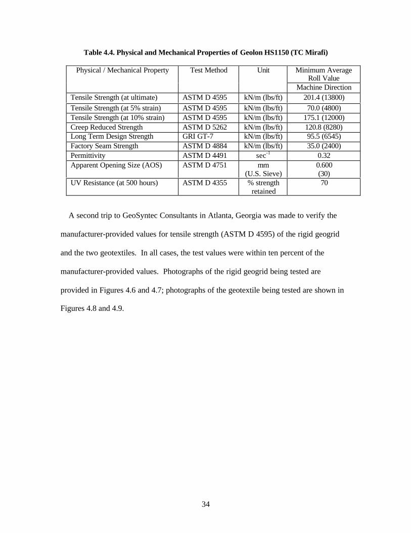
Table 4.4. Physical and Mechanical Properties of Geolon HS1150 (TC Mirafi)
Minimum AverageRoll Value
Physical / Mechanical Property Test Method Unit
Machine DirectionTensile Strength (at ultimate) ASTM D 4595 kN/m (lbs/ft) 201.4 (13800)Tensile Strength (at 5% strain) ASTM D 4595 kN/m (lbs/ft) 70.0 (4800)Tensile Strength (at 10% strain) ASTM D 4595 kN/m (lbs/ft) 175.1 (12000)Creep Reduced Strength ASTM D 5262 kN/m (lbs/ft) 120.8 (8280)Long Term Design Strength GRI GT-7 kN/m (lbs/ft) 95.5 (6545)Factory Seam Strength ASTM D 4884 kN/m (lbs/ft) 35.0 (2400)Permittivity ASTM D 4491 sec-1 0.32Apparent Opening Size (AOS) ASTM D 4751 mm
(U.S. Sieve)0.600(30)
UV Resistance (at 500 hours) ASTM D 4355 % strengthretained
70
A second trip to GeoSyntec Consultants in Atlanta, Georgia was made to verify the
manufacturer-provided values for tensile strength (ASTM D 4595) of the rigid geogrid
and the two geotextiles. In all cases, the test values were within ten percent of the
manufacturer-provided values. Photographs of the rigid geogrid being tested are
provided in Figures 4.6 and 4.7; photographs of the geotextile being tested are shown in
Figures 4.8 and 4.9.

35
Figure 4.6. Wide Width Tensile Test on Enkagrid MAX 20 (before loading)
Figure 4.7. Wide Width Tensile Test on Enkagrid MAX 20 (after loading)

36
Figure 4.8. Wide Width Tensile Test on Geolon HS800 (before loading)
Figure 4.9. Wide Width Tensile Test on Geolon HS800 (after loading)

37
CHAPTER 5: SOILS
Two samples of Piedmont residual soil were used in this research program. The soil
was obtained from ongoing NCDOT roadway construction projects in the Charlotte area.
Mr. Clint Little of the NCDOT was instrumental in identifying appropriate sources of
material and arranging delivery to the geotechnical laboratories at UNC Charlotte. The PI
is indebted to Mr. Little and his associates for their willing cooperation in this vital aspect
of this research project.
Once the two soils were delivered, they were minimally processed and appropriate
material characterization tests were performed. These items are described for both soils
in the following sections.
5.1. Soil Preparation
Processing of the soil proceeded as follows. Large soil clumps were broken down by
hand and shovel, and any trash, organic material and rocks greater than 4” nominal
diameter were removed by hand and discarded. The soil was passed through a large, 483
mm by 483 mm (19 in by 19 in), sieve with 19 mm (0.75 in) openings. This sieve was
placed over a 55-gallon (208 L) drum. The soil was worked through the sieve to produce
soil with a maximum particle size of 19 mm in the drum. Once a drum was partially
filled with the processed soil, it was emptied into a 2 cubic yard, Wright self-dumping
steel hopper. After all the soil obtained from the NCDOT had been processed and stored
in the hopper, representative samples were taken for classification and other laboratory

38
testing. One hopper was used for each soil type. Once filled with soil, the hoppers were
covered and moved to a storage area located adjacent to the testing laboratory.
5.2 Soil #1 (A-2-4)
5.2.1 Classification
The processed soil was classified according to the American Association of State
Highway and Transportation Officials (AASHTO), AASHTO M-145, as A-2-4.
Classification was performed independently in the geotechnical engineering laboratories
at UNC Charlotte and at the NCDOT Materials and Tests Unit.
5.2.2 Soil Properties
The grain size distribution was determined in general accordance with ASTM D 422.
Results are shown in Table 5.1 and Figure 5.1.
Table 5.1. Soil#1 Grain Size Distribution
Sieve Size Percent Passed
3/8” 99.4
#4 98.5
#10 95
#16 89.2
#40 62
#100 36.4
#200 22.1

39
0
10
20
30
40
50
60
70
80
90
100
0.0010.0100.1001.00010.000
Sieve Size (mm)
% P
assi
ng
Figure 5.1. Soil #1 Grain Size Distribution Curve
The Atterberg Limits of the soil were determined in general accordance with ASTM D
4318. The Atterberg Limits establish states of consistency of the soil and are used in soil
classification. The Liquid Limit of Soil #1 was 24% and the Plastic Limit was 28%. The
difference between the Liquid Limit and the Plastic Limit is the Plasticity Index (PI) of
the soil. In this case, since the Liquid Limit and Plastic Limit values are essentially the
same, the soil is deemed non-plastic.
Specific gravity (Gs) relates the weight of soil solids to the weight of water and is a
dimensionless value. The procedure for determining the specific gravity of a soil is
ASTM D 854. The Gs of Soil #1 was found to be 2.79.
The moisture-unit weight relationship (compaction characteristics) of the soil was
determined by using the standard Proctor test (ASTM D 698). The test results indicate a

40
maximum dry density of 121.3 pcf at an optimum moisture content (OMC) of 11.8%.
The standard Proctor curve is shown in Figure 5.2.
117.5
118
118.5
119
119.5
120
120.5
121
121.5
7 8 9 10 11 12 13 14 15 16 17
Moisture Content (%)
Dry
Un
it W
eig
ht (
pcf
)
Figure 5.2. Soil #1 Standard Proctor Curve
Table 5.2. Summary of Soil #1 Properties
Soil Properties
AASHTO Classification A-2-4% Fines 22.1
Liquid Limit (LL) 24%Plastic Limit (PL) 28%Plastic Index (PI) NP
Specific Gravity (Gs) 2.79Optimum Moisture Content 11.8% *
Maximum Dry Unit Weight (?max) 121.3 pcf *
* based on Standard Proctor Test (ASTM D 698)

41
5.3 Soil #2 (A-4)
5.3.1 Classification
The processed soil was classified according to the American Association of State
Highway and Transportation Officials (AASHTO), AASHTO M-145, as A-4.
Classification was performed independently in the geotechnical engineering laboratories
at UNC Charlotte and at the NCDOT Materials and Tests Unit.
5.3.2 Soil Properties
The grain size distribution was determined in general accordance with ASTM D 422.
Results are shown in Table 5.3 and Figure 5.3.
Table 5.3 Soil#2 Grain Size Distribution
Sieve Size Percent Passed
3/8” 100
#4 99.5
#10 99.4
#40 79.7
#100 48.9
#200 36.0

42
0
10
20
30
40
50
60
70
80
90
100
0.0010.010.1110
Sieve Size (mm)
% P
assi
ng
Figure 5.3. Soil #2 Grain Size Distribution Curve
The Atterberg Limits of the soil were determined in general accordance with ASTM D
4318. The Atterberg Limits establish states of consistency of the soil and are used in soil
classification. The Liquid Limit of Soil #2 was 37% and the Plastic Limit was 31%. The
difference between the Liquid Limit and the Plastic Limit is the Plasticity Index (PI) of
the soil. In this case, since the Plasticity Index for Soil #2 is 6.
Specific gravity (Gs) relates the weight of soil solids to the weight of water and is a
dimensionless value. The procedure for determining the specific gravity of a soil is
ASTM D 854. The Gs of Soil #2 was found to be 2.78.
The moisture-unit weight relationship (compaction characteristics) of the soil was
determined by using the standard Proctor test (ASTM D 698). The test results indicate a

43
maximum dry density of 107.1 pcf at an optimum moisture content (OMC) of 17.1%.
The standard Proctor curve is shown in Figure 5.4.
117.5
118
118.5
119
119.5
120
120.5
121
121.5
7 8 9 10 11 12 13 14 15 16 17
Moisture Content (%)
Dry
Un
it W
eig
ht (
pcf
)
Figure 5.4. Soil #2 Standard Proctor Curve
Table 5.4. Summary of Soil #2 Properties
Soil Properties
AASHTO Classification A-4% Fines 36.0
Liquid Limit (LL) 37%Plastic Limit (PL) 31%Plastic Index (PI) 6
Specific Gravity (Gs) 2.78Optimum Moisture Content 17.1% *
Maximum Dry Unit Weight (?max) 107.1 pcf *
* based on Standard Proctor Test (ASTM D 698)

44
5.4. Soil Handling and Compaction
In addition to the 2 cubic yard self-dumping hoppers, 55-gallon drums were used for
both storage and delivery of the soil to the pullout box. Moving the soil filled drums was
accomplished using a Clark forklift (model LPS, 1588 kg maximum capacity) and a
Wesco drum lifter (363 kg maximum capacity) (Figure 5.5). The forklift and drum lifter
combination was used to move and lift the soil filled drums over the rear wall of the
pullout box.
Figure 5.5. Clark Forklift and Wesco 55-gallon Drum Lifter
For testing, the moisture content of the soil in the drums was adjusted to within 2% of
the OMC. When the target moisture content was achieved, the drums were sealed and
moved to a staging and storage area.
The moisture and unit weight relationship of the soil was used to determine the weight
of soil need to achieve 95% of the Standard Proctor maximum dry density when

45
compacted. Before conducting a pullout test, the moisture content of the soil was
checked and adjusted if necessary. The moisture content and lift volume were calculated
to determine the weight needed for a particular lift.
A Whacker Packer jumping jack tamp and a 152 mm by 254 mm rectangular and
tamp weighing 93 kg were used to compact the soil. The target dry density (95% of the
Standard Proctor maximum dry density) was achieved when the soil lift was compacted
to a final lift thickness of 6 cm.
The in-place density of the compacted soil was determined using the sand cone
(ASTM D 1556). These tests were performed in one of four locations. The interior of
the pullout box was separated into four equal quadrants. Each of the locations
corresponded to one of the four quadrants. Test locations were: 1 rear left, 2 rear right, 3
front right, and 4 front left (Figure 5.6).
Figure 5.6. Sand Cone Density Test Locations
Front of Pullout Box
4
1
3
2

46
CHAPTER 6: TEST EQUIPMENT AND PROCEDURES
6.1. Pullout Box
The overall outside dimensions of the pullout box are 2.3 m (L) X 1.4 m (W) X 0.7 m
(D). The inside length (embedment) dimension is adjustable from 0.95 m to 1.5 m by use
of an interior wall insert. For the test program, the inside dimensions were 1.2 m (W) X
1.5 m (L) X 0.6 m (D).
The pullout box is constructed of hot-rolled A36 structural steel sections including
steel channels, tubes, and angles (Figure 6.1). The sections are connected with 19 mm
A325 structural bolts and beveled washers.
Figure 6.1. Front View of Pullout Box

47
The A36 steel component sections of the pullout box are as follows:
• The two sidewalls are constructed of two 2.13 m long C12X25 channels
stacked on their sides and bolted together (Figure 6.2). Two 13 mm thick A36
steel plates are welded on the inside ends of each channel (Figure 6.3).
• The cover and floor are constructed of seven 1.37 m long C12X25 channels
each individually bolted to the sidewalls (Figure 6.4).
• The front and rear walls are constructed of one 1.37 m long 102 mm by 76
mm steel rectangular tube bolted between two 1.37 m long C10x30 channels
(Figure 6.5).
• The wall insert is constructed of three 1.22 m long C8x11.5 channels stacked
and supported by four 0.6 m long L3X3X0.25 angles bolted to the sidewalls
(Figure 6.6).
Figure 6.2. Pullout Box Sidewalls

48
Figure 6.3. Steel Plates on Inside Ends of Each Sidewall
Figure 6.4. Cover and Floor Individually Bolted to the Sidewalls

49
Figure 6.5. Rear and Sidewall
Figure 6.6. Stacked Rear Wall Insert

50
The interior wall insert is slotted to allow telltale wires to attach to the rear LVDT
instrumentation located outside of the confining soil mass. The 0.9 m wide by 25 mm
high slot is positioned 0.3 m above the pullout box’s interior bottom and is the same
elevation as the geosynthetic test specimen. A custom clamp device (constructed with
steel legs and a wooden jaw) held the rear LVDTs in place during testing (Figure 6.7)
Figure 6.7. Rear LVDT Clamp Device
The front wall’s steel rectangular tube is constructed with a centered 0.9 m wide by 25
mm high slot. This slot has four A36 steel plates welded perpendicular to the tubing
walls to provide a continuous and level slot into the pullout box interior. An interior
sleeve is formed by two 0.15 m long by 1.22 m wide by 3.2 mm thick cold-rolled steel
angles. One leg of an angle is welded to the interior front wall face above the slot. The
other angle is welded similarly but it is below the front wall slot to form the sleeve. For

51
strength, both legs of the angles forming the sleeve are built-up with two additional 3.2
mm thick cold-rolled steel plates welded in a stepwise fashion (Figure 6.8).
Figure 6.8. Cross Section Through Front of Pullout Box (not to scale)
6.2. Pullout Bar
The pullout bar transfers the applied tensile force to the entire width of the
geosynthetic test specimen. The geosynthetic sample is kept horizontal when it is
attached to the pullout bar., which ensures planar application of tensile force.
The pullout bar is constructed of hot-rolled A36 structural steel, rubber inserts, rubber
lined plywood, bolts, and wheel stands (Figure 6.9). The pullout bar clamp consists of
Steel Sleeve Angles
Compacted Soil Front ofPullout Box

52
various welded A36 steel plates. The front and rear housing walls are constructed with
91 cm long by 2.5 cm high slots to allow for placement of the geosynthetic test specimen
through the pullout bar’s housing.
Figure 6.9. Pullout Bar
A rubber sheet was placed on the bottom of the housing followed by a plywood insert
wrapped in two layers of rubber. A final rubber sheet and steel plate were placed on top
of the preceding inserts. The geosynthetic test specimen was locked between the inserts
and secured to the pullout bar by nine 9 mm diameter bolts through the steel cover plate,
inserts, and the bottom of the housing (Figure 6.10).
The housing rests on wheel stands to allow for free movement of the pullout bar away
from the pullout box. A 102 cm long by 30.5 cm wide by 2.5 cm high channel is used
under each wheel stand to ensure a level and smooth rolling surface. Each wheel stand is
constructed of a 50 mm diameter pipe welded to the midpoint of a 0.6 m long by 25 mm

53
GeogridSteel
Rubber
Wood
Schedule 40 PVCpipe
CoverPlate
Pullout BarHousing
9 mmDiameter Bolt
wide by 50 mm high rectangular steel pipe. Two 50 mm diameter wheel casters are
welded to the underside of each wheel stand. The wheel caster positioned closest to the
pullout box is fixed in the direction of the tensile force being applied. However, the
wheel caster farthest from the pullout box is free to rotate.
Figure 6.10. Cut Away of Pullout Bar (not to scale)
6.3. Pullout Force
Tensile force is required to pull the geosynthetic specimen out of the confining soil
mass within the pullout box. The tensile force is applied to the pullout bar (and gripped
geosynthetic) by two spring return hydraulic rams. Each hydraulic ram has an output
capacity of over 220 KN and a stroke of 260 mm.
One hydraulic ram is connected to the pullout box on each side of the front wall

54
sleeved slot. Each ram is connected to the pullout box via a hinge connection with a 25
mm pin. The hydraulic ram piston is secured to the pullout bar by a 13 mm bolt screwed
directly into the piston through a hole in the pullout bar steel plate housing (Figure 6.11).
Figure 6.11. Hydraulic Ram Connection to Pullout Bar Housing
The system supplying hydraulic pressure to the rams includes an OTC electric-
powered hydraulic pump and a four position, three way, metered, temperature, and
pressure compensated flow control valve. The pump and control valve are connected to
the rams by various hydraulic hoses and fittings.
6.4. Surcharge Pressure
A vertical surcharge pressure, normal to the geosynthetic plane of embedment, is
provided to test the geosynthetic under a range of confining pressures. Increasing the
surcharge pressure inside the pullout box increases the geosynthetic’s confining pressure.

55
Increasing the vertical surcharge pressure in the pullout box is accomplished by
pressurizing the 1.6 m long by 1.2 m wide, 90-mil PVC flexible air bladder (Figure 6.12).
An air valve with a three-meter long pressure hose is attached to the air bladder. The
three-meter long pressure hose is attached to the laboratory supplied constant pressurized
air line. The air bladder is maintained at a constant pressure by using an inline pressure
regulator (Porter model 8290) and a pressure dial gauge (USG) (Figure 6.13).
Figure 6.12. Flexible Air Bladder

56
Figure 6.13. Inline Pressure Regulator and Pressure Dial Gauge
6.5. Data Acquisition System
A computerized data acquisition system (DAQ) was employed to record and store data
from the pullout tests. The DAQ can display data in real-time from multiple input
channels. The DAQ used in this research consisted of four components:
1. Computer hardware and software
2. Data acquisition device hardware
3. Data acquisition software
4. Electronic Transducers
Each of these components is described in the following paragraphs. The computer and
data acquisition device hardware are shown in Figure 6.14.

57
Figure 6.14. Computer and Data Acquisition Hardware
The computer was an IBM compatible Gateway with a Pentium II 333 MHz MMX
processor. The computer was equipped with 64 Megabytes of RAM and operated under
the Windows NT Version 4.0 Build 1381 with Service Pack 3 operating system.
Most of the data acquisition device hardware consisted of National Instruments
products except for the custom constructed electronic instrumentation relay-box (EIRB).
The National Instruments hardware components consisted of the following:
• PCI DAQ board in the computer (model PCI-MIO-16E-4)
• A 12 slot chassis (model SCXI-1001)
• Two four channel isolation amplifier with excitation modules (model SCXI-1121)
• Two terminal block connectors for the SCXI-1121 (model SCXI-1321)
• A 32 channel differential multiplexer/amplifier module (model SCXI-1100)
• A terminal block connector for the SCXI-1100 (model SCXI 1303)

58
The EIRB was designed and fabricated at UNC-Charlotte. It is the multi-port
component in the center of Figure 6.15. This device allows for the application of the
proper excitation voltage to individual transducers. The EIRB also allowed quick
connect and disconnect of instrumentation to the DAQ by use of standard 9 pin (DB9)
connectors. This was accomplished by hardwiring all necessary connections for the
transducers to each DB9 connector. The transducer was wired to a “male” BD9 and
connected to a “female” BD9 on the EIRB. The “female” DB9 represents a specific
channel in the DAQ. The channels were configured through the National Instruments
software (i.e., gain and calibration). This allows the same channel to perform data
acquisition from various transducer types (strain gage, pressure transducer, LVDT, etc).
Figure 6.15. Electronic Instrumentation Relay-Box
The data acquisition software was National Instruments LabVIEW Version. 5.1.
LabVIEW allows for interfacing the electronic transducers through the DAQ hardware by

59
means of the LabVIEW graphic language, G. Specific DAQ programs called virtual
instruments (VIs) were written in G by the user to allow for a totally user definable DAQ
system. The user defines and writes the VI to perform the specific data acquisition
required.
The electronic transducers consisted of two pressure transducers (Setra Systems Inc.,
model 280E) and six LVDTs (Schlumberger Industries models DC25 and DC50). The
electronic transducers were excited by two variable power supply units (Leader model
LPS-151). These two units were used to excite the LVDTs and pressure transducers by
10 and 24 volts, respectively.
The pressure transducers measured the hydraulic pressure applied to the pullout bar
rams, and ultimately, the force applied to the geosynthetic. Two LVDTs (model DC50)
were used to measure the displacement of the pullout bar. One LVDT was attached to
each hydraulic ram. These LVDTs were monitored during testing to ensure a constant
strain rate of 1 mm/min was maintained. Three LVDTs (model DC25) were attached
within the embedded portion of the geosynthetic by telltales. The sixth LVDT (model
DC25) was attached to the geosynthetic at the front opening of the pullout box.
6.6. Instrument Calibration
Calibration of the electronic transducers correlates the electronic signals they produce
(volts) to physical measurement units (mm and kPa). The pressure transducers were
calibrated using a hand calibrating hydraulic pump (Ralston Instruments) and a voltmeter.
A change in applied pressures was correlated with the change in voltage. The linear
function was graphed and inputted into LabVIEW to calibrate the pressure traducers’

60
voltage change to pressure change. The LVDTs were calibrated using a custom
fabricated calibration device (Figure 6.16) and the DAQ.
Figure 6.16. LVDT Calibration Device
A calibration VI was written in LabVIEW to facilitate the use of the DAQ in the
calibration process. Each of the LVDTs was placed vertically in the calibration device.
The device held the LVDT in place and allowed the extension rod to extend and retract
from the LVDT housing in uniform increments. The LVDT was excited and wired to the
DAQ. The increase or decrease in displacement was correlated with the change in
voltage. The linear range for each LVDT was established and the associated calibration
file was saved for each instrument. Because a VI was written to calibrate the LVDTs, the
calibration data was input directly into LabVIEW for future VIs using these instruments.
An example LVDT calibration curve is shown in Figure 6.17.

61
y = 5.4091xR2 = 0.9994
-25
-20
-15
-10
-5
0
5
10
15
20
25
-5 -4 -3 -2 -1 0 1 2 3 4 5
Voltage (volts)
Dis
plac
emen
t (m
m)
Figure 6.17. LVDT Calibration Chart
6.7. Test Procedure
The tasks performed for each test included: soil preparation, geosynthetic preparation,
soil placement and compaction, geosynthetic placement, instrumentation setup, pullout
box and pullout bar setup, test performance, and post test tasks.
The soil preparation first consisted of determining the moisture content of the soil.
The weight of soil needed for each lift was placed in one 55 gal drum. After the soil lifts
were sealed into drums the geosynthetic specimen was prepared.
The geosynthetic was cut to test dimensions and three telltale wires were connected to
the geosynthetic. The wires were connected to the geosynthetic by twisting steel fishing
leader at the desired locations (i.e., ¼, ½, and ¾ of the embedment depth and width)
(Figure 6.18).
After the geosynthetic test specimen and soil were prepared the placement and

62
compaction of the lower lift commenced. The lower 180 mm of the pullout box (same
elevation as the front wall opening) was filled with soil in loose lifts, leveled across the
test area, and compacted by a combination of mechanical and hand tamping to a final
depth of 60 mm. Each lift was compacted to a target density of 95% of the Standard
Proctor maximum dry density. A chalk line was laid on the last of the lower lifts to form
a centered construction line for placement of the test specimen.
Figure 6.18. Typical Telltale Connections
The prepared geosynthetic test specimen was placed inside the pullout box and
drawn through the front wall opening. The geosynthetic was aligned with the chalk line
and measurements made to ensure proper embedment depth. The telltale wires were
threaded through 3 mm diameter aluminum tubing to ensure the surcharge loads would
not hinder the wire’s movement. Finally, pretest photographs where taken of the
geosynthetic as it appeared in the pullout box.

63
After the placement of the geosynthetic, soil was hand placed over the geosynthetic to
ensure no movement of the test specimen during the placement of the first overburden
soil layer. The upper 180 mm of the pullout box was filled with soil and compacted in the
same manner as the lower half of the pullout box.
Following the soil and geosynthetic placement, the pullout box was readied for
testing. A non-woven needle punched geotextile cut to the pullout box inside plan
dimensions was placed over the last soil lift to protect the air bladder from the soil layer.
Next, an air bladder, also constructed to the pullout box inside plan dimensions, was
placed over the geotextile. The air bladder was followed by a plywood spacer cut to the
same inside dimensions for protection from the steel channels. A hose was connected to
the air valve of the air bladder and fed through a drilled hole in the plywood spacer. The
top of the box was comprised of six channels placed across the pullout box from sidewall
to sidewall. The channels were attached to the sidewalls with bolts tightened with an
impact wrench. The hose attached to the bladder’s air valve was fed through a drilled
hole in the center channel.
The freeboard portion of the geosynthetic extending out of the pullout box’s front
opening was connected to the pullout bar. The geosynthetic was drawn through the front
opening of the pullout bar over a rubber insert and out the rear opening. The
geosynthetic was pulled taut, wrapped over a piece of Schedule 40 PVC pipe, and fed
back through the rear opening of the pullout bar. This process was conducted to remove
slack from the test specimen. A plywood insert lined with a rubber sheet on both sides
was placed over the geosynthetic. The geosynthetic was laid over the rubber lined
plywood insert and through the front opening of the pullout bar. A final rubber insert

64
was placed over the geosynthetic test specimen. This process was conducted while
maintaining tension on the test specimen. A steel cover plate insert was placed over the
final rubber insert and attached to the pullout bar with two equally spaced rows of 9 mm
diameter bolts.
The pullout box and pullout bar were set for the test. The DAQ instrumentation was
attached to the in-place geosynthetic test specimen and pullout bar:
1. One LVDT was attached to each of the two pressure rams.
2. An LVDT was attached to the freeboard portion of the geosynthetic,approximately 10 mm from the front pullout box opening.
3. The three telltales from the geosynthetic were connected to the three rear pulloutbox LVDTs.
Next, the DAQ was prepared for testing. The front and rear LVDTs and pressure
transducer lead wires were connected to their respective channels on the DAQ relay box.
The DAQ computer and hardware warm up was initiated. The DAQ software was started
and software and hardware pretest checks performed. The LVDTs were adjusted to the
linear range limit to achieve the maximum range of data acquisition.
The test was ready to begin after the air bladder was inflated and maintained at the
desired surcharge pressure for a minimum of one hour. After the hour of airbladder
seating time, the DAQ software program was initiated and the hydraulic pump was turned
on to begin application of the pullout force. The loading rate was maintained at 1
mm/min for results relative to near static testing. Test termination occurred when the
load decreased relative to an increase in time and displacement. Test termination
occurred approximately 3 hours after initiation of the test.

65
After test termination, the hydraulic pump was turned off and the load removed from
the test specimen. The air bladder was depressurized to remove the surcharge. The data
acquired by the DAQ was saved and the files immediately backed up. DAQ hardware
and software were shut down and the LVDT and pressure transducer lead wires were
unplugged from the EIRB. The LVDTs were removed from the pullout box and stored.
The pullout box lid channels, geotextile, air bladder, plywood spacer, and overburden soil
were removed down to a level 30 mm above the geosynthetic. The 30 mm of soil over
the geosynthetic was removed by careful excavation using brushes and small tools so as
not to disturb post-test geosynthetic orientation. After excavation of the geosynthetic,
post-test photographs where taken of the geosynthetic as it appeared in the pullout box.
The geosynthetic and remaining soil were removed from the pullout box. All soil
removed was placed in random 55-gallon drums to disperse the material throughout the
next soil lifts. Images portraying typical testing procedures are given in Figures 6.19 to
6.33.

66
Figure 6.19. Fork Lift & 2-Cubic Yard Hopper of Soil
Figure 6.20. Spreading Moisture-Conditioned Soil

67
Figure 6.21. Mechanical Compaction of Soil
Figure 6.22. Mechanical Compaction

68
Figure 6.23. Sand Cone Density Test
Figure 6.24. Deployment of Geotextile Specimen

69
Figure 6.25. Smoothing Embedded Portion of Geotextile Specimen
Figure 6.26. LVDT Telltales in Protective Tubing

70
Figure 6.27. Hand Tamping Directly Over Geosynthetic Specimen
Figure 6.28. Final Stages of Sample Preparation

71
Figure 6.29. Rear LVDT Clamping Mechanism
Figure 6.30. Securing Geotextile Specimen into Pullbar

72
Figure 6.31. Attaching LVDT to Hydraulic Ram
Figure 6.32. Setting Confining Pressure

73
Figure 6.33. Post-Test Excavation

74
CHAPTER 7: TEST RESULTS
The individual test results are presented in this chapter. A total of 25 different tests
were performed in this project. The complete test matrix is shown in Table 7.1. Table
7.1 contains five columns of information: project test number, test name, soil type,
reinforcement type, and confining pressure. The project test numbers were assigned
chronologically, so the first test is No. 1 and the last test is No. 25. The test name
consists of four parts: the date performed (month and day), the soil type, the
reinforcement type, and the confining pressure. The soil classified as A-2-4 was deemed
Soil No. 1; the soil classified as A-4 was deemed Soil No. 2. The shorthand notation for
the geosynthetic reinforcement is as follows:
FGG Flexible Geogrid
HSGT High Strength Geotextile
LSGT Low Strength Geotextile
RGG Rigid Geogrid
The confining pressure is given in pounds per square inch (psi) and is either 1, 2, 4, or 8
psi, depending on the geosynthetic product being tested.
Two of the twenty-five tests were “empty box” tests used to calibrate the hydraulic
loading system (Project Test Nos. 19 and 25). Representative results from this type of
test are shown immediately following Table 7.1. This figure present load versus
displacement data for the hydraulic loading system with no geosynthetic attached to the
pullbar. This represents, among other things, both the static and “rolling” friction
inherent in the system during any test. These system loads were taken into account when
presenting results from actual geosynthetic pullout tests.

75
Two test configurations were repeated. Project Test Nos. 1 and 23 both tested the A-
2-4 soil with the flexible geogrid under a 4 psi confining pressure. Project Test Nos. 7
and 24 both tested the A-2-4 soil with the low strength geotextile under a 4 psi confining
pressure. These tests were repeated to improve the overall quality of the data collected.
In the remainder of this chapter, figures of individual test results are presented. Pairs
of plots are presented for twenty-one tests (Project Test Nos. 3-18 and 20-24). The first
of the paired figures presents a plot of applied load verses ram displacement; the second
figure presents geosynthetic displacements verses ram displacement. Geosynthetic
displacements were measured at three locations embedded in the soil and at the front of
the pullbox. The embedded locations are deemed, Rear Right, Rear Middle, and Rear
Left. The Rear Right location is at the ¼ point closest to the front of the pullbox (15 cm
from the front of the box). The Rear Middle location is at the center of the embedded
sample (30 cm from the front of the box), and the Rear Left location is at the ¾ point on
the embedded sample (45 cm from the front of the box). These figures are arranged
chronologically and can be identified by the Test Name as listed in Table 7.1.

76
Table 7.1. Pullout Test Matrix
Project TestNumber
Test Name Soil Type(Class II,Type 2)
ReinforcementType
ConfiningPressure (psi)
1 Feb28-1-FGG-4 A-2-4 Flexible Geogrid 42 Mar06-1-FGG-8 A-2-4 Flexible Geogrid 83 Mar07-1-FGG-4 A-2-4 Flexible Geogrid 44 Mar21-1-FGG-2 A-2-4 Flexible Geogrid 25 Apr12-1-HSGT-4 A-2-4 High Strength
Geotextile4
6 Apr16-1-HSGT-8 A-2-4 High StrengthGeotextile
8
7 Apr20-1-LSGT-4 A-2-4 Low StrengthGeotextile
4
8 Apr27-1-RGG-4 A-2-4 Rigid Geogrid 49 May06-1-RGG-2 A-2-4 Rigid Geogrid 210 May10-1-RGG-1 A-2-4 Rigid Geogrid 111 May15-2-FGG-4 A-4 Flexible Geogrid 412 May17-2-FGG-2 A-4 Flexible Geogrid 213 May18-2-RGG-4 A-4 Rigid Geogrid 414 May22-2-RGG-2 A-4 Rigid Geogrid 215 May23-2-LSGT-4 A-4 Low Strength
Geotextile4
16 May24-2-HSGT-4 A-4 High StrengthGeotextile
4
17 May29-2-HSGT-2 A-4 High StrengthGeotextile
2
18 May30-2-LSGT-2 A-4 Low StrengthGeotextile
2
19 Empty box 1 none none none20 Jun04-2-FGG-4 A-4 Flexible Geogrid 421 Jun06-2-FGG-2 A-4 Flexible Geogrid 222 Jun8-2-FGG-1 A-4 Flexible Geogrid 123 Jun25-1-FGG-4 A-4 Flexible Geogrid 424 Jun27-1-LSGT-4 A-4 Low Strength
Geotextile4
25 Empty box 2 none none none

RamTest2
y = 0.0146x + 0.073R2 = 0.9988
0.00
0.50
1.00
1.50
2.00
2.50
3.00
3.50
4.00
0.00 50.00 100.00 150.00 200.00 250.00
Average Ram Displacement (mm)
To
tal L
oad
(kN
)

Mar07-1-FGG-4
0.00
5.00
10.00
15.00
20.00
25.00
30.00
35.00
0.00 50.00 100.00 150.00 200.00 250.00
Average Ram Displacement (mm)
Un
it L
oad
(kN
/m)

Mar07-1-FGG-4
0.00
20.00
40.00
60.00
80.00
100.00
120.00
140.00
160.00
180.00
200.00
0.00 50.00 100.00 150.00 200.00 250.00
Average Ram Displacement (mm)
Dis
pla
cem
ent
(mm
)
Front Center LVDT
Rear Right LVDT
Rear Middle LVDT
Rear Left LVDT

Mar21-1-FGG-2
0.00
5.00
10.00
15.00
20.00
25.00
30.00
35.00
0.00 50.00 100.00 150.00 200.00 250.00
Average Ram Displacement (mm)
Un
it L
oad
(kN
/m)

Mar21-1-FGG-2
0.00
20.00
40.00
60.00
80.00
100.00
120.00
140.00
160.00
180.00
200.00
0.00 50.00 100.00 150.00 200.00 250.00
Average Ram Displacement (mm)
Dis
pla
cem
ent
(mm
)
Front Center LVDT
Rear Right LVDT
Rear Middle LVDT
Rear Left LVDT

Apr12-1-HSGT-4
0.00
5.00
10.00
15.00
20.00
25.00
30.00
35.00
0.00 50.00 100.00 150.00 200.00 250.00
Average Ram Displacement (mm)
Un
it L
oad
(kN
/m)

Apr12-1-HSGT-4
0.00
20.00
40.00
60.00
80.00
100.00
120.00
140.00
160.00
180.00
200.00
0.00 50.00 100.00 150.00 200.00 250.00
Ram Displacement (mm)
Dis
pla
cem
ent
(mm
)
Front Center LVDT
Rear Right LVDT
Rear Middle LVDT
Rear Left LVDT

Apr16-1-HSGT-8
0.00
10.00
20.00
30.00
40.00
50.00
60.00
0.00 50.00 100.00 150.00 200.00 250.00
Average Ram Displacement (mm)
Un
it L
oad
(kN
/m)

Apr16-1-HSGT-8
0.00
20.00
40.00
60.00
80.00
100.00
120.00
140.00
160.00
180.00
200.00
0.00 50.00 100.00 150.00 200.00 250.00
Average Ram Displacement (mm)
Dis
pla
cem
ent
(mm
)
Front Center LVDT
Rear Right LVDT
Rear Middle LVDT
Rear Left LVDT

Apr20-1-LSGT-4
0.00
5.00
10.00
15.00
20.00
25.00
30.00
35.00
0.00 50.00 100.00 150.00 200.00 250.00
Average Ram Displacement (mm)
Un
it L
oad
(kN
/m)

Apr20-1-LSGT-4
0.00
20.00
40.00
60.00
80.00
100.00
120.00
140.00
160.00
180.00
200.00
0.00 50.00 100.00 150.00 200.00 250.00
Average Ram Displacement (mm)
Dis
pla
cem
ent
(mm
)
Front Center LVDT
Rear Right LVDT
Rear Middle LVDT
Rear Left LVDT

Apr27-1-RGG-4
0.00
5.00
10.00
15.00
20.00
25.00
30.00
35.00
0.00 50.00 100.00 150.00 200.00 250.00
Average Ram Displacement (mm)
Un
it L
oad
(kN
/m)

Apr27-1-RGG-4
0.00
20.00
40.00
60.00
80.00
100.00
120.00
140.00
160.00
180.00
200.00
0.00 50.00 100.00 150.00 200.00 250.00
Average Ram Displacement (mm)
Dis
pla
cem
ent
(mm
)
Front Center LVDT
Right Rear LVDT
Rear Middle LVDT
Rear Left LVDT

Apr27-1-RGG-4-ZOOM
0.00
0.50
1.00
1.50
2.00
2.50
3.00
3.50
4.00
0.00 20.00 40.00 60.00 80.00 100.00 120.00 140.00 160.00
Average Ram Displacement (mm)
Dis
pla
cem
ent
(mm
)
Rear Right LVDT
Rear Middle LVDT
Rear Left LVDT

May06-1-RGG-2
0.00
5.00
10.00
15.00
20.00
25.00
30.00
35.00
0.00 50.00 100.00 150.00 200.00 250.00
Average Ram Displacement (mm)
Un
it L
oad
(kN
/m)

May06-1-RGG-2
0.00
20.00
40.00
60.00
80.00
100.00
120.00
140.00
160.00
180.00
200.00
0.00 50.00 100.00 150.00 200.00 250.00
Average Ram Displacement (mm)
Dis
pla
cem
ent
(mm
)
Front Center LVDT
Rear Right LVDT
Rear Middle LVDT
Rear Left LVDT

May06-1-RGG-2-ZOOM
0.00
1.00
2.00
3.00
4.00
5.00
6.00
7.00
8.00
9.00
0.00 20.00 40.00 60.00 80.00 100.00 120.00 140.00 160.00 180.00
Average Ram Displacement (mm)
Dis
pla
cem
ent
(mm
)
Rear Right LVDT
Rear Middle LVDT
Rear Left LVDT

May10-1-RGG-1
0.00
5.00
10.00
15.00
20.00
25.00
30.00
35.00
0.00 50.00 100.00 150.00 200.00 250.00
Average Ram Displacement (mm)
Un
it L
oad
(kN
/m)

May10-1-RGG-1
0.00
20.00
40.00
60.00
80.00
100.00
120.00
140.00
160.00
180.00
200.00
0.00 50.00 100.00 150.00 200.00 250.00
Average Ram Displacement
Dis
pla
cem
ent
(mm
)
Front Center LVDT
Rear Right LVDT
Rear Middle LVDT
Rear Left LVDT

May10-1-RGG-1-ZOOM
0.00
5.00
10.00
15.00
20.00
25.00
0.00 20.00 40.00 60.00 80.00 100.00 120.00 140.00 160.00 180.00 200.00
Average Ram Displacement
Dis
pla
cem
ent
(mm
)
Rear Right LVDT
Rear Middle LVDT
Rear Left LVDT

May15-2-FGG-4
0.00
5.00
10.00
15.00
20.00
25.00
30.00
35.00
0.00 50.00 100.00 150.00 200.00 250.00
Average Ram Displacement (mm)
Un
it L
oad
(kN
/m)

May15-2-FGG-4
0.00
20.00
40.00
60.00
80.00
100.00
120.00
140.00
160.00
180.00
200.00
0.00 50.00 100.00 150.00 200.00 250.00
Average Ram Displacement (mm)
Dis
pla
cem
ent
(mm
)
Front Center LVDT
Rear Right LVDT
Rear Middle LVDT
Rear Left LVDT
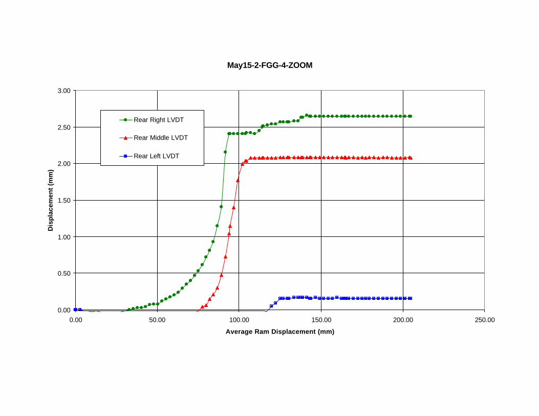
May15-2-FGG-4-ZOOM
0.00
0.50
1.00
1.50
2.00
2.50
3.00
0.00 50.00 100.00 150.00 200.00 250.00
Average Ram Displacement (mm)
Dis
pla
cem
ent
(mm
)
Rear Right LVDT
Rear Middle LVDT
Rear Left LVDT

May17-2-FGG-2
0.00
5.00
10.00
15.00
20.00
25.00
30.00
35.00
0.00 50.00 100.00 150.00 200.00 250.00
Average Ram Displacement (mm)
Un
it L
oad
(kN
/m)

May17-2-FGG-2
0.00
20.00
40.00
60.00
80.00
100.00
120.00
140.00
160.00
180.00
200.00
0.00 50.00 100.00 150.00 200.00 250.00
Average Ram Displacement (mm)
Dis
pla
cem
ent
(mm
)
Front Center LVDT
Rear Right LVDT
Rear Middle LVDT
Rear LeftLVDT

May17-2-FGG-2-ZOOM
0.00
0.50
1.00
1.50
2.00
2.50
3.00
3.50
4.00
4.50
0.00 20.00 40.00 60.00 80.00 100.00 120.00 140.00 160.00 180.00 200.00
Average Ram Displacement (mm)
Dis
pla
cem
ent
(mm
)
Rear Right LVDT
Rear Middle LVDT
Rear Left LVDT

May18-2-RGG-4
0.00
5.00
10.00
15.00
20.00
25.00
30.00
35.00
0.00 50.00 100.00 150.00 200.00 250.00
Average Ram Displacement (mm)
Un
it L
oad
(kN
/m)

May18-2-RGG-4
0.00
20.00
40.00
60.00
80.00
100.00
120.00
140.00
160.00
180.00
200.00
0.00 50.00 100.00 150.00 200.00 250.00
Average Ram Displacement (mm)
Dis
pla
cem
ent
(mm
)
Front Center LVDT
Rear Right LVDT
Rear Middle LVDT
Rear Left LVDT

May18-2-RGG-4-ZOOM
0.00
2.00
4.00
6.00
8.00
10.00
12.00
0.00 20.00 40.00 60.00 80.00 100.00 120.00 140.00 160.00
Average Ram Displacement (mm)
Dis
pla
cem
ent
(mm
)
Rear Right LVDT
Rear Middle LVDT
Rear Left LVDT

May22-2-RGG-2
0.00
5.00
10.00
15.00
20.00
25.00
30.00
35.00
0.00 50.00 100.00 150.00 200.00 250.00
Average Ram Displacement (mm)
Un
it L
oad
(kN
/m)

May22-2-RGG-2
0.00
20.00
40.00
60.00
80.00
100.00
120.00
140.00
160.00
180.00
200.00
0.00 50.00 100.00 150.00 200.00 250.00
Average Ram Displacement (mm)
Dis
pla
cem
ent
(mm
)
Front Center LVDT
Rear Right LVDT
Rear Middle LVDT
Rear Left LVDT

May22-2-RGG-2-ZOOM
0.00
2.00
4.00
6.00
8.00
10.00
12.00
0.00 20.00 40.00 60.00 80.00 100.00 120.00 140.00 160.00 180.00
Average Ram Displacement (mm)
Dis
pla
cem
ent
(mm
)
Rear Right LVDT
Rear Middle LVDT
Rear Left LVDT

May23-3-LSGT-4
0.00
5.00
10.00
15.00
20.00
25.00
30.00
35.00
0.00 50.00 100.00 150.00 200.00 250.00
Average Ram Displacement (mm)
Un
it L
oad
(kN
/m)

May23-2-LSGT-4
0.00
20.00
40.00
60.00
80.00
100.00
120.00
140.00
160.00
180.00
200.00
0.00 50.00 100.00 150.00 200.00 250.00
Average Ram Displacement (mm)
Dis
pla
cem
ent
(mm
)
Front Center LVDT
Rear Right LVDT
Rear Middle LVDT
Rear Left LVDT

May24-2-HSGT-4
0.00
5.00
10.00
15.00
20.00
25.00
30.00
35.00
0.00 50.00 100.00 150.00 200.00 250.00
Average Ram Displacement (mm)
Un
it L
oad
(kN
/m)

May24-2-HSGT-4
0.00
20.00
40.00
60.00
80.00
100.00
120.00
140.00
160.00
180.00
200.00
0.00 50.00 100.00 150.00 200.00 250.00
Ave. Ram Displacement (mm)
Dis
pla
cem
ent
(mm
)
Front Center LVDT
Rear Right LVDT
Rear Middle LVDT
Rear Left LVDT

May29-2-HSGT-2
0.00
5.00
10.00
15.00
20.00
25.00
30.00
35.00
0.00 50.00 100.00 150.00 200.00 250.00
Average Ram Displacement (mm)
Un
it L
oad
(kN
/m)

May29-2-HSGT-2
0.00
20.00
40.00
60.00
80.00
100.00
120.00
140.00
160.00
180.00
200.00
0.00 50.00 100.00 150.00 200.00 250.00
Ram Displacement (mm)
Dis
pla
cem
ent
(mm
)
Front Center LVDT
Rear Right LVDT
Rear Middle LVDT
Rear Left LVDT

May30-2-LSGT-2
0.00
5.00
10.00
15.00
20.00
25.00
30.00
35.00
0.00 50.00 100.00 150.00 200.00 250.00
Average Ram Displacement (mm)
Un
it L
oad
(kN
/m)

May30-2-LSGT-2
0.00
20.00
40.00
60.00
80.00
100.00
120.00
140.00
160.00
180.00
200.00
0.00 50.00 100.00 150.00 200.00 250.00
Average Ram Displacemet (mm)
Dis
pla
cem
ent
(mm
)
Front Center LVDT
Rear Right LVDT
Rear Middle LVDT
Rear Left LVDT

June04-2-FGG-4
0.00
5.00
10.00
15.00
20.00
25.00
30.00
35.00
0.00 50.00 100.00 150.00 200.00 250.00
Average Ram Displacement (mm)
Un
it L
oad
(kN
/m)

June04-2-FGG-4
0.00
20.00
40.00
60.00
80.00
100.00
120.00
140.00
160.00
180.00
200.00
0.00 50.00 100.00 150.00 200.00 250.00
Average Ram Displacement (mm)
Dis
pla
cem
ent
(mm
)
Front Center LVDT
Rear Right LVDT
Rear Middle LVDT
Rear Left LVDT

June04-2-FGG-4-ZOOM
0.00
1.00
2.00
3.00
4.00
5.00
6.00
7.00
8.00
9.00
0.00 20.00 40.00 60.00 80.00 100.00 120.00 140.00 160.00 180.00 200.00
Average Ram Displacement (mm)
Dis
pla
cem
ent
(mm
)
"Rear Right LVDT"
"Rear Middle LVDT"
"Rear Left LVDT"

June06-2-FGG-2
0.00
5.00
10.00
15.00
20.00
25.00
30.00
35.00
0.00 50.00 100.00 150.00 200.00 250.00
Average Ram Displacement (mm)
Un
it L
oad
(kN
/m)

June06-2-FGG-2
0.00
20.00
40.00
60.00
80.00
100.00
120.00
140.00
160.00
180.00
200.00
0.00 50.00 100.00 150.00 200.00 250.00
Average Ram Displacement (mm)
Dis
pla
cem
ent
(mm
)
Front Center LVDT
Rear Right LVDT
Rear Middle LVDT
Rear Left LVDT

June06-2-FGG-2-ZOOM
0.00
2.00
4.00
6.00
8.00
10.00
12.00
14.00
16.00
0.00 20.00 40.00 60.00 80.00 100.00 120.00 140.00 160.00 180.00 200.00
Average Ram Displacement (mm)
Dis
pla
cem
ent
(mm
)
Rear Right LVDT
Rear Middle LVDT
Rear Left LVDT

June08-2-FGG-1
0.00
5.00
10.00
15.00
20.00
25.00
30.00
35.00
0.00 50.00 100.00 150.00 200.00 250.00
Average Ram Displacement (mm)
Un
it L
oad
(kN
/m)

June08-2-FGG-1
0.00
20.00
40.00
60.00
80.00
100.00
120.00
140.00
160.00
180.00
200.00
0.00 50.00 100.00 150.00 200.00 250.00
Average Ram Displacement (mm)
Dis
pla
cem
ent
(mm
)
Front Center LVDT
Rear Right LVDT
Rear Middle LVDT
Rear Left LVDT

June25-1-FGG-4
0.00
5.00
10.00
15.00
20.00
25.00
30.00
35.00
0.00 50.00 100.00 150.00 200.00 250.00
Average Ram Displacement (mm)
Un
it L
oad
(kN
/m)

June25-1-FGG-4
0.00
20.00
40.00
60.00
80.00
100.00
120.00
140.00
160.00
180.00
200.00
0.00 50.00 100.00 150.00 200.00 250.00
Average Ram Displacement (mm)
Dis
pla
cem
ent
(mm
)
Front Center LVDT
Rear Right LVDT
Rear Middle LVDT
Rear Left LVDT

June25-1-FGG-4-ZOOM
0.00
2.00
4.00
6.00
8.00
10.00
12.00
0.00 20.00 40.00 60.00 80.00 100.00 120.00 140.00 160.00
Average Ram Displacement (mm)
Dis
pla
cem
ent
(mm
)
Rear Right LVDT
Rear Middle LVDT
Rear Left LVDT

June27-1-LSGT-4
0.00
5.00
10.00
15.00
20.00
25.00
30.00
35.00
0.00 50.00 100.00 150.00 200.00 250.00
Average Ram Displacement (mm)
Un
it L
oad
(kN
/m)

June27-1-LSGT-4
0.00
20.00
40.00
60.00
80.00
100.00
120.00
140.00
160.00
180.00
200.00
0.00 50.00 100.00 150.00 200.00 250.00
Average Ram Displacement (mm)
Dis
pla
cem
ent
(mm
)
Front Center LVDT
Rear Right LVDT
Rear Middle LVDT
Rear Left LVDT

130
CHAPTER 8: ANALYSIS AND INTERPRETATION
8.1. Parametric Combinations
For easy reference, the complete test matrix is repeated in Table 8.1.
Table 8.1. Pullout Test Matrix
Project TestNumber
Test Name Soil Type(Class II,Type 2)
ReinforcementType
ConfiningPressure (psi)
1 Feb28-1-FGG-4 A-2-4 Flexible Geogrid 42 Mar06-1-FGG-8 A-2-4 Flexible Geogrid 83 Mar07-1-FGG-4 A-2-4 Flexible Geogrid 44 Mar21-1-FGG-2 A-2-4 Flexible Geogrid 25 Apr12-1-HSGT-4 A-2-4 High Strength
Geotextile4
6 Apr16-1-HSGT-8 A-2-4 High StrengthGeotextile
8
7 Apr20-1-LSGT-4 A-2-4 Low StrengthGeotextile
4
8 Apr27-1-RGG-4 A-2-4 Rigid Geogrid 49 May06-1-RGG-2 A-2-4 Rigid Geogrid 210 May10-1-RGG-1 A-2-4 Rigid Geogrid 111 May15-2-FGG-4 A-4 Flexible Geogrid 412 May17-2-FGG-2 A-4 Flexible Geogrid 213 May18-2-RGG-4 A-4 Rigid Geogrid 414 May22-2-RGG-2 A-4 Rigid Geogrid 215 May23-2-LSGT-4 A-4 Low Strength
Geotextile4
16 May24-2-HSGT-4 A-4 High StrengthGeotextile
4
17 May29-2-HSGT-2 A-4 High StrengthGeotextile
2
18 May30-2-LSGT-2 A-4 Low StrengthGeotextile
2
19 Empty box 1 none none none20 Jun04-2-FGG-4 A-4 Flexible Geogrid 421 Jun06-2-FGG-2 A-4 Flexible Geogrid 222 Jun8-2-FGG-1 A-4 Flexible Geogrid 123 Jun25-1-FGG-4 A-4 Flexible Geogrid 424 Jun27-1-LSGT-4 A-4 Low Strength
Geotextile4
25 Empty box 2 none none none

131
The analysis and interpretation of these tests can be performed in a variety of ways.
Since this testing program was essentially a parametric study, one clear way is to
examine the results in that manner. The three parameters that were varied included the
soil type, the reinforcement type, and the confining pressure. Tests can be grouped to
assess the effects of these three parameters in the following ways:
1. Same soil type, same confining pressure, different reinforcement types.
2. Different soil type, same confining pressure, same reinforcement type.
3. Same soil type, different confining pressures, same reinforcement type
The tests are grouped according to these three combinations in Tables 8.2a, 8.2b, and
8.2c. Observations on test results within each of these categories are presented in the
following sections.
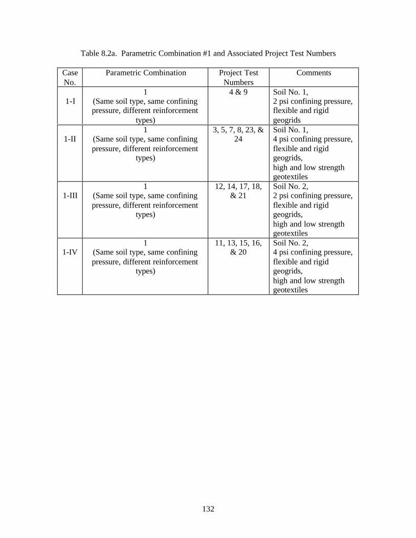
132
Table 8.2a. Parametric Combination #1 and Associated Project Test Numbers
CaseNo.
Parametric Combination Project TestNumbers
Comments
1-I1
(Same soil type, same confiningpressure, different reinforcement
types)
4 & 9 Soil No. 1,2 psi confining pressure,flexible and rigidgeogrids
1-II1
(Same soil type, same confiningpressure, different reinforcement
types)
3, 5, 7, 8, 23, &24
Soil No. 1,4 psi confining pressure,flexible and rigidgeogrids,high and low strengthgeotextiles
1-III1
(Same soil type, same confiningpressure, different reinforcement
types)
12, 14, 17, 18,& 21
Soil No. 2,2 psi confining pressure,flexible and rigidgeogrids,high and low strengthgeotextiles
1-IV1
(Same soil type, same confiningpressure, different reinforcement
types)
11, 13, 15, 16,& 20
Soil No. 2,4 psi confining pressure,flexible and rigidgeogrids,high and low strengthgeotextiles

133
Table 8.2b. Parametric Combination #2 and Associated Project Test Numbers
CaseNo.
Parametric Combination Project TestNumbers
Comments
2-I2
(Different soil type, same confiningpressure, same reinforcement type)
4 & 12 Soil Nos. 1 & 2,2 psi confining pressure,flexible geogrid
2-II2
(Different soil type, same confiningpressure, same reinforcement type)
9 & 14 Soil Nos. 1 & 2,2 psi confining pressure,rigid geogrid
2-III2
(Different soil type, same confiningpressure, same reinforcement type)
3, 11, 20, & 23 Soil Nos. 1 & 2,4 psi confining pressure,flexible geogrid
2-IV2
(Different soil type, same confiningpressure, same reinforcement type)
5 & 16 Soil Nos. 1 & 2,4 psi confining pressure,high strength geotextile
2-V2
(Different soil type, same confiningpressure, same reinforcement type)
7, 15, & 24 Soil Nos. 1 & 2,4 psi confining pressure,low strength geotextile
2-VI2
(Different soil type, same confiningpressure, same reinforcement type)
8 & 13 Soil Nos. 1 & 2,4 psi confining pressure,rigid geogrid

134
Table 8.2c. Parametric Combination #3 and Associated Project Test Numbers
CaseNo.
Parametric Combination Project TestNumbers
Comments
3-I3
(Same soil type, differentconfining pressure, same
reinforcement type)
3, 4, & 23 Soil No. 1,flexible geogrid,2 & 4 psi confiningpressure
3-II3
(Same soil type, differentconfining pressure, same
reinforcement type)
5 & 6 Soil No. 1,high strength geotextile,4 & 8 psi confiningpressure
3-III3
(Same soil type, differentconfining pressure, same
reinforcement type)
8, 9, & 10 Soil No. 1,rigid geogrid,1, 2 & 4 psi confiningpressure
3-IV3
(Same soil type, differentconfining pressure, same
reinforcement type)
11, 12, 20, 21,& 22
Soil No. 2,flexible geogrid,1, 2, & 4 psi confiningpressure
3-V3
(Same soil type, differentconfining pressure, same
reinforcement type)
13 & 14 Soil No. 2,rigid geogrid,2 & 4 psi confiningpressure
3-VI3
(Same soil type, differentconfining pressure, same
reinforcement type)
15 & 18 Soil No. 2,low strength geotextile,2 & 4 psi confiningpressure
3-VII3
(Same soil type, differentconfining pressure, same
reinforcement type)
16 & 17 Soil No. 2,high strength geotextile,2 & 4 psi confiningpressure

135
8.2. Parametric Combination #1
In Parametric Combination #1, the soil type and confining pressure was held constant
and different geosynthetic reinforcement types were used. This combination gives a
“side by side” comparison of the load versus displacement behavior of the reinforcing
materials when embedded in the selected Piedmont residual soils. In this research
program, there were four individual cases where the effects of Parametric Combination
#1 could be examined. These are given in Table 8.2a.
The results of the four cases of Parametric Combination #1 are summarized in Table
8.3. Since load versus deformation information is most important, the measured values
of peak load (per unit width of material) and the corresponding hydraulic ram
displacement are provided for comparison.
In interpreting the data presented in Table 8.3, several items are worth noting. First, in
general, the flexible geogrid exhibited better performance than the rigid geogrid. In
virtually all cases, the flexible geogrid carried a higher peak load at a lower displacement.
Second, under lower confining pressure (2 psi), the geogrids and the geotextiles tended to
behave very similarly. The geogrids exhibited higher peak strengths than the geotextiles,
but these peaks occurred at much larger displacements than those for the geotextiles.
This is an important observation when displacement is an important performance
consideration. Finally, under higher confining pressures (4 psi), the geotextiles exhibited
peak loads approximately equal to the geogrids while undergoing displacements less than
half as large. Again, this is an important observation with respect to minimizing
displacements.

136
Table 8.3. Summary of Parametric Combination #1 Results
CaseNo.
Variable(geosynthetic type)
Peak Load(kN/m)
RamDisplacement @Peak Load (mm)
Comments
Flexible geogrid 32 951-IRigid geogrid 21 130
Soil No. 1,2 psi confining pressure
Flexible geogrid 28 112Rigid geogrid 22 128High strength
geotextile17 48
1-II
Low strengthgeotextile
28 50
Soil No. 1,4 psi confining pressure
Flexible geogrid 21 110Rigid geogrid 22 120High strength
geotextile14.5 60
1-III
Low strengthgeotextile
10 60
Soil No. 2,2 psi confining pressure
Flexible geogrid 32 115Rigid geogrid 22 125High strength
geotextile27.5 50
1-IV
Low strengthgeotextile
29 50
Soil No. 2,4 psi confining pressure

137
8.3. Parametric Combination #2
In Parametric Combination #2, the confining pressure and geosynthetic reinforcement
type was held constant and different soil types were used. This combination gives insight
into how much of an effect the soil type, particularly the “lower quality” soils selected,
has on the load versus displacement behavior of the reinforcing materials. In this
research program, there were six individual cases where the effects of Parametric
Combination #2 could be examined. These are given in Table 8.2b. Again, this
information is not available from other sources.
The results of the six cases of Parametric Combination #2 are summarized in Table
8.4. Since load versus deformation information is most important, the measured values
of peak load (per unit width of material) and the corresponding hydraulic ram
displacement are provided for comparison.
In interpreting the data presented in Table 8.4, several items are worth noting. First,
the magnitudes of the displacements at peak load do not appear to be sensitive to the soil
type. However, as seen in Parametric Combination #1 data, the displacements at peak
load for the geotextiles tend to be less than half of the displacements at peak load for the
geogrids. Second, the peak loads carried by the geogrid materials are not strongly
affected by varying the soil type. Conversely, the peak loads carried by the geotextiles
are very strongly affected by the soil type. For both the low and high strength
geotextiles, the peak load with Soil No. 2 was nearly double the peak load with Soil No.
1. This is a significant observation.

138
Table 8.4. Summary of Parametric Combination #2 Results
CaseNo.
Variable(soil type)
Peak Load(kN/m)
RamDisplacement @Peak Load (mm)
Comments
Soil No. 1 32 962-ISoil No. 2 22 110
2 psi conf. pressure,flexible geogrid
Soil No. 1 22 1302-IISoil No. 2 22.5 130
2 psi conf. pressure,rigid geogrid
Soil No. 1 29 1102-IIISoil No. 2 32 112
4 psi conf. pressure,flexible geogrid
Soil No. 1 17 502-IVSoil No. 2 27 50
4 psi conf. pressure,high strength geotextile
Soil No. 1 15.5 602-VSoil No. 2 29 55
4 psi conf. pressure,low strength geotextile
Soil No. 1 22.5 1302-VISoil No. 2 22 130
4 psi conf. Pressure,rigid geogrid

139
8.4. Parametric Combination #3
In Parametric Combination #3, the soil type and geosynthetic reinforcement type were
held constant and different confining pressures were used. This combination gives
insight into how a particular combination of soil and geosynthetic reinforcing material
will interact at different heights along a retaining wall. Typically, the soil- geosynthetic
interaction behavior near the top of the wall (where confining pressures are lower) is
different than the interaction behavior near the bottom of the wall (where confining
pressures are higher). In this research program, there were seven individual cases where
the effects of Parametric Combination #3 could be examined. These are given in Table
8.2c.
The results of the seven cases of Parametric Combination #3 are summarized in Table
8.5. Since load versus deformation information is most important, the measured values
of peak load (per unit width of material) and the corresponding hydraulic ram
displacement are provided for comparison.
In interpreting the data presented in Table 8.5, several items are worth noting. For the
geogrids, the peak load tends to increase slightly with increasing confining pressure, but
appears to be relatively insensitive to the range of confining pressures used in this study.
However, the same is not true for the geotextiles. Both the low and high strength
geotextiles exhibited substantial increases in peak load under increased confining
pressure. The peak loads nearly tripled when the confining pressure was doubled. This
is a significant observation. Consistent with the other parametric combinations, the
geotextiles typically experienced less than half the displacement of the geogrids at peak
load. Again, this is important to know when displacements are an issue.

140
Table 8.5. Summary of Parametric Combination #3 Results
CaseNo.
Variable(confining pressure)
Peak Load(kN/m)
RamDisplacement @Peak Load (mm)
Comments
2 psi 32 953-I 4 psi 29 112
Soil No. 1,Flexible geogrid
4 psi 17 503-II8 psi 50 90
Soil No. 1,High strength geotextile
1 psi 19 1302 psi 21 130
3-III
4 psi 23 130
Soil No. 1,Rigid geogrid
1 psi 27 1152 psi 30 116
3-IV
4 psi 33 115
Soil No. 2,Flexible geogrid
2 psi 22 1303-V4 psi 22 130
Soil No. 2,Rigid geogrid
2 psi 10 583-VI4 psi 29 55
Soil No. 2,Low strength geotextile
2 psi 14.5 603-VI4 psi 28 50
Soil No. 2,High strength geotextile

141
CHAPTER 9: CONCLUSIONS AND RECOMMENDATIONS
9.1. Conclusions
The following conclusions are based on the activities performed during this
research program. It is important to note these conclusions are based on research
performed with four specific geosynthetic reinforcing materials embedded in two types
of Piedmont residual soil. While certainly representative of overall behavior, the
extension to general conclusions for all geogrid products or reinforced soil types may
not be appropriate.
• A large database of soil- geosynthetic reinforcement interaction behavior
has been developed. This data is particularly relevant to the work
conducted by the NCDOT as it uses local, Piedmont residuum.
• Parametric studies have been performed to examine the importance of soil
type, reinforcement type, and confining pressure on the load transfer
mechanisms of geosynthetic-reinforced soils.
• The results of this study indicate that geotextile reinforcing materials may
be a better choice than geogrid materials, particularly if minimizing
displacement is an important performance consideration.
• Based on measurements of load and displacement, the use of “lower
quality” soils appears feasible.

142
9.2. Recommendations
Based on the results of this research program, the following recommendations are
made:
• For temporary earth retaining structures, it is feasible to use “lower quality”
backfill in the reinforced zone. Material that satisfies the Class II – Type 2
classification in Section 1016-3 of the NCDOT Standard Specifications for
Roads and Structures may be used provided the material is placed and
compacted properly. As with virtually all projects employing earth as an
engineering material, proper placement is absolutely critical if desired
performance is to be achieved.
• It appears that the geotextile products may be the better choice of geosynthetic
reinforcing material, provided the confining pressure is sufficiently large.
• The next appropriate step is to extend this laboratory-based study to the field.
This may be achieved by constructing and monitoring prototype-scale
temporary retaining walls either on the UNC Charlotte campus or at a more
desirable location for the NCDOT personnel. These walls should be built
using the same types of soil as used in this research program (Class II – Type
2) and be reinforced with, as a minimum, a representative variety of
geotextiles. Performance monitoring should focus primarily on deformations
(both horizontal and vertical) and should be made throughout the construction
process and for at least 18 months afterward. At that point, the walls should
be loaded to failure (destructive testing) to glean as much design and
performance information as possible.

143
REFERENCES
AASHTO, “Standard Specifications for Highway Bridges”, 15th edition with appropriateinterim specifications, American Association of State Highway and TransportationOfficials, Inc., Washington, D.C., 1992 and later for interim specifications.
Alfaro, M.C., Mitura, N., and Bergado, D.T., “Soil-Geogrid Reinforcement Interaction byPullout and Direct Shear Tests.” Geotechnical Testing Journal, GTJODJ, Vol. 18, No. 2,June 1995, pp. 157-167.
American Society for Testing and Materials. ASTM Standards on Geosynthetics.Sponsored by ASTM Committee D-35 on Geosynthetics. 4th ed. Pennsylvania:Philadelphia, 1995.
Balzer, E., Delmas, P., Matichard, Y., Sere, A., and Thamm, B.R., “GeotextileReinforced Abutment : Full Scale Test and Theory”, Performance of Reinforced SoilStructures, McGowan, A., Yeo, K.C., and Andrawes, K.Z., Editors, Thomas Telford,Ltd., London, 1991, Proceedings of a conference held in Glasgow, UK, sep 1990, pp. 47-52.
Bauer, G.E., Halim, A.O.A., and Shang, Q., “Large-Scale Pullout Tests: Assessment ofProcedure and Results”, Proceedings of Geosynthetics ’91, Vol. 2, Atlanta, GA, USA,IFAI, Feb 1991, pp. 615-627.
Berg, R.R. and Swan, R.H., “Investigation into Geogrid Pullout Mechanism”,Performance of Reinforced Soil Structures, McGowan, A., Yeo, K.C., and Andrawes,K.Z., Editors, Thomas Telford, Ltd., London, 1991, Proceedings of a conference held inGlasgow, UK, sep 1990, pp. 353-357.
Billiard, J.W. and Wu, J.T.H., “Load Test of a Large-Scale Geotextile-ReinforcedRetaining Wall”, Proceedings of Geosynthetics ’91, Vol. 2, Atlanta, GA, USA, IFAI, Feb1991, pp. 537-548.
Bonaparte, R., Holtz, R.D., and Giroud, J.P., “Soil Reinforcement Design UsingGeotextiles and Geogrids”, Geotextile Testing and the Design Engineer, J.E. Fluet, Jr.,Editor, ASTM STP 952, 1987, Proceedings of a Symposium held in Los Angeles, CA,USA, Jun 1985, pp. 69-116.
Bonaparte, R. and Swan, R.H., “Geosynthetic Reinforcement of Embankment Slopes”,Geosynthetics in Geotechnics, Proceedings of the 1990 Chicago Geotechnical LectureSeries, ASCE Illinois Section, Chicago Il, USA, Feb-Mar 1990, 20 p.
Brand, S.R., and Duffy, D.M., “Strength and Pullout Testing of Geogrids”, Proceedingsof Geosynthetics ’87, Vol. 1, New Orleans, LA, USA, IFAI, Feb 1987, pp. 226-236.

144
Breitenbach, A.J. and Swan, R.H. (1999) “Influence of High Load Deformations onGeomembrane Liner Interface Strengths”, Proceedings of the Geosynthetics ’99Conference, Vol. 1, pp. 517-529, Boston, Massachusetts.
Brown, D, Thiel, R., Brummer, C.J. and Huvane, S.V. (1999) “Innovative Design andConstruction of Landfill Side-Slope Liners in High Seismic Risk Areas, A Case Study”,Proceedings of the Geosynthetics ’99 Conference, Vol. 1, pp. 589-599, Boston,Massachusetts.
Buttry, K., McCullough, E., and Wetzel, R., “Pullout Testing for Modular ConcreteRetaining Walls Reinforced with Geogrid”, Design and Construction with Geosynthetics,Proceedings of the 22nd Ohio River Valley Soils Seminar held in Lexington, KY, USA,Oct 1991, pp. 2.1-2.6.
Cancelli, A., Rimoldi, P., and Togni, S., “Frictional Characteristics of Geogrids by Meansof Direct Shear and Pull-Out Tests”, Earth Reinforcement Practice, Ochiai, H., Hayashi,S., and Otani, J., Eds., Proceedings of a symposium held in Fukuoka, Kyushu, Japan, Nov1992, Vol. 1., pp. 51-56.
Carroll, R.G., and Richardson, G.N., “Geosynthetic Reinforced Retaining Walls”,Proceedings of the Third International Conference on Geotextiles, Vol. 2, Vienna,Austria, Apr 1986, pp. 389-394.
Chan D.H., Yi C.T. and Scott J.D. (1993) “An interpretation of the Pull-Out Test”,Proceedings of the Geosynthetics ’93 Conference, Vol. 2, pp. 593-605, Vancouver,Canada.
Chang, D.T.T., Chang, F.C., Yang, G.S. and Yan, C.Y. (2000) “The Influence Factors forGeogrid Pullout Test”, Grips, Clamps, Clamping Techniques, and Strain Measurement forTesting of Geosynthetics, ASTM STP 1379, P.E. Stevenson, Ed., American Society forTesting and Materials, West Conshohocken, PA.
Chang, D.T.-T., Wey, W.-T., and Chen, T.-C. (1993) “Study on Geotextile Behaviors ofTensile Strength and Pull-Out Capacity Under Confined Condition”, Proceedings of theGeosynthetics ’93 Conference, Vol. 2, pp. 607-618, Vancouver, Canada.
Chen, R.H. and Lee, Y.S. (1998) “A Model for the Ultimate Pull-Out Resistance ofGeogrids”, Proceedings of the Sixth International Conference on Geosynthetics, Vol. 2, pp.721-724, Atlanta, Georgia.
Chew, S.H., Wong, W.K., Ng, C.C., Tan, S.A. and Karunaratne, G.P. (2000) “StrainGauging Geotextiles Using External Gauge Attachment Method”, Grips, Clamps,Clamping Techniques, and Strain Measurement for Testing of Geosynthetics, ASTM STP1379, P.E. Stevenson, Ed., American Society for Testing and Materials, WestConshohocken, PA.
Chew, S.H., Tan, S.A., Loke, K.H., Delmas, P. and Ho, C.T. (1998) “Large Scale PulloutTests of Geotextile in Poorly Draining Soils”, Proceedings of the Sixth InternationalConference on Geosynthetics, Vol. 2, pp. 821-824, Atlanta, Georgia.
Cowell M.J. and Sprague C.J. (1993) “Comparison of Pull-Out Performance of Geogridsand Geotextiles”, Proceedings of the Geosynthetics ’93 Conference, Vol. 2, pp. 579-592,Vancouver, Canada.

145
De, A. and Zimmie, T.F. (1999) “Estimation of Dynamic Frictional Properties of GeonetInterfaces”, Proceedings of the Geosynthetics ’99 Conference, Vol. 1, pp. 545-558, Boston,Massachusetts.
Department of Transportation. Federal Highway Administration. Reinforced SoilStructures. Volume 1. Design and Construction Guidelines. By STS Consultants Ltd.U.S. Department of Commerce, National Technical Information Service, Springfield,VA, 1990.
Devata, M.S., “Geogrid Reinforced Earth Embankments with Steep Side Slopes”,Polymer Grid Reinforcement, Thomas Telford Ltd., 1985, Proceedings of a conferenceheld in London, U.K. Mar 1984, pp. 82-87.
Dove, J.E. and Harpring, J.C. (1999) “Geometric and Spatial Parameters for Analysis ofGeomembrane/Soil Interface Behavior”, Proceedings of the Geosynthetics ’99Conference, Vol. 1, pp. 575-588, Boston, Massachusetts.
El-Fermaoui, A., and Nowtzki, E., “Effect of Confining Pressure on Performance ofGeotextiles in Soils”, Proceedings of the Second of International Conference onGeotextiles, Vol. 3, Las Vegas, NV, USA, Aug 1982, pp. 799-804.
Fannin, R.J. and Raju, D.M. (1993) “Large-Scale Pull-Out Test Results onGeosynthetics”, Proceedings of the Geosynthetics ’93 Conference, Vol. 2, pp. 633-643,Vancouver, Canada.
Fannin, R.J. and Raju, D.M., “Pullout Resistance of Geosynthetics”, Proceedings of the44th Canadian Geotechnical Conference, Canadian Geotechnical Society, Calgary,Alberta, Canada, Sep-Oct 1991, pp. 81.1-81.8.
Farrag, K. and Morvant, M. (2000) “Effect of Clamping Mechanism on Pullout andConfined Extension Tests”, Grips, Clamps, Clamping Techniques, and Strain Measurementfor Testing of Geosynthetics, ASTM STP 1379, P.E. Stevenson, Ed., American Society forTesting and Materials, West Conshohocken, PA.
Frost, J.D., Lee, S. and Cargill, P.E. (1999) “The Evolution of Sand Structure Adjacent toGeomembranes”, Proceedings of the Geosynthetics ’99 Conference, Vol. 1, pp. 559-574,Boston, Massachusetts.
Holtz, R.D., “Soil Reinforcement with Geotextiles”, Soil Improvement Methods,Proceedings of the Third International Geotechnical Seminar, Nanyang TechnologicalInstitute, Singapore, Nov 1985, pp. 55-74.
Hutchins, R.D., “Behavior of Geotextiles in Embankment Reinforcement”, Proceedingsof the Second International Conference on Geotextiles, Vol. 3, Las Vegas, NV, USA Aug1982, pp.617-619.
Ingold, T.S., “An Analytical Study of Geotextile Reinforced Embankments”, Proceedingsof the Second International Conference on Geotextiles, Vol. 3, Las Vegas, NV, USA Aug1982, pp.683-688.

146
Juran, I., Knochenmus, G., Acar, Y.B., and Arman, A., “Pull-Out Response ofGeotextiles and Geogrids (Synthesis of Available Experimental Data)”, Geosynthetics forSoil Improvement, R.D. Holtz, Editor, Geotechnical Special Publication No. 18, ASCE,Proceedings of a symposium held in Nashville, TN, USA, May 1988, pp. 92-111.
Karmokar, A.K. and Kabeya H. (1998) “An Approach to Analyze the Pull-Out Resistanceof Woven Geotextiles”, Proceedings of the Sixth International Conference onGeosynthetics, Vol. 2, pp. 725-728, Atlanta, Georgia.
Kate, J.M., Katti, A.R., and Rao, G.V., “Geogrid Testing and Behavior”, Role ofGeosynthetics in Water Resource Projects, Central Board of Irrigation and Power,Publication No. 232, Proceedings of a Symposium held in New Delhi, India, Jan 1992,pp. 50-57.
Koerner, R.M., “Geosynthetics: Design, Testing and Performance”, Geosynthetics:Design and Performance, Proceedings of the 6th Vancouver Geotechnical SocietySymposium, Vancouver, B.C., Canada, The Canadian Geotechnical Society, BiTechPublishers Ltd., May 1991, 20 p.
Koerner, R.M., “Designing with Geosynthetics”, 4th edition, Prentice-Hall, Inc., UpperSaddle River, New Jersey, 1998.
Koerner, R.M. and Soong, T., “The Evolution of Geosynthetics.” Civil Engineering, Jul97, Vol. 67, Issue 7, pp. 62-64.
Koutsourais, M., Sandri, D. and Swan, R.H. (1998) “Soil Interaction Characteristics ofGeotextiles and Geogrids”, Proceedings of the Sixth International Conference onGeosynthetics, Vol. 2, pp. 739-744, Atlanta, Georgia.
Leshchinsky, D., “Geosynthetic Reinforced Wall: Post Failure Analysis”, Geosynthetic-Reinforced Soil Retaining Walls, Wu, J.T.H., Ed., Balkema, 1992, Proceedings of theInternational Symposium on Geosynthetic-Reinforced Soil Retaining Walls, Denver,CO, USA, Aug 1991, pp. 173-178.
Li, M. and Gilbert, R.B. (1999) “Shear Strength of Textured Geomembrane andNonwoven Geotextile Interfaces”, Proceedings of the Geosynthetics ’99 Conference, Vol.1, pp. 505-516, Boston, Massachusetts.
Lo, S.C.R., “Pull-Out Resistance of Polyester Straps at Low Overburden Stress”,Geosynthetics International, Volume 5, Number 4, 1998.
Lopes, M.L. and Ayele, T. (1998) “Influence of Reinforcement Damage on the Pull-outResistance of Geogrids”, Proceedings of the Sixth International Conference onGeosynthetics, Vol. 2, pp. 1183-1188, Atlanta, Georgia.
Lopes, M.J., and Lopes, M.L., “Soil- Geosynthetic Interaction-Influence of Soil ParticleSize and Geosynthetic Structure.” Geosynthetics International, Vol. 6, No. 4, 1999
Lopes, M.J. and Lopes, M.L. (1999) “Errata for ‘Soil-Geosynthetic Interaction – Influenceof Soil Particle Size and Geosynthetic Structure’”, Geosysnthetics International, Vol. 6, pp.449-453, Roseville, Minnesota.

147
Luellen, J.R., Dove, J.E., Swan, R.H. and Johnson, M.L. (1999) “The Design of aReduced Strength Landfill Liner Interface for Seismic Loading Conditions”, Proceedingsof the Geosynthetics ’99 Conference, Vol. 1, pp. 531-544, Boston, Massachusetts.
Madhav, M.R., N. Gurung, and Y. Iwao, “A Theoretical Model for the Pull-OutResponse of Geosynthetic Reinforcement”, Geosynthetics International, Volume 5,Number 4, 1998.
Mallick, S.B. and Zhai, H. (1995) “A Laboratory Study on Pull-Out Performance ofWoven Geotextiles”, Proceedings of the Geosynthetics ’95 Conference, Vol. 3, pp. 1169-1178, Nashville, Tennessee.
Mallick, S.B., Elton, D.J. and Adanur, S. (1998) “A New Approach in Modeling of Soil-Geotextile Interface Behavior in Pullout Tests”, Proceedings of the Sixth InternationalConference on Geosynthetics, Vol. 2, pp. 729-732, Atlanta, Georgia.
Mallick, S., Elton, D.J. and Adanur, S. (1997) “An Experimental Characterization ofSoil-Woven Geotextile Interface in Large-Box Pull-out Tests”, Proceedings of theGeosynthetics ’97 Conference, Vol. 2, pp. 927-940, Long Beach, California.
Miki, H., Fukuda, N., and Taki, M., “Analysis and Prediction for Geosynthetic-Reinforced Soil Retaining Walls”, Geosynthetic-Reinforced Soil Retaining Walls, Wu,J.T.H., Ed., Balkema, 1992, Proceedings of the International Symposium onGeosynthetic-Reinforced Soil Retaining Walls, Denver, CO, USA, Aug 1991, pp. 173-178.
Milligan, V., and Busbridge, J., “Geotextiles and Geogrids in Embankments”,Proceedings of the Symposium on the use of Geotextiles, Geogrids and Geomembranesin Engineering Practice, The Canadian Geotechnical Society, Southern Ontario Section,Toronto, Onatrio, Canada, Nov 1984, pp. 41-63.
Mitachi, T, Yamamoto, Y., and Muraki, S., “Estimation of In-Soil Deformation Behaviorof Geogrid Under Pull-Out Loading”, Earth Reinforcement Practice, Ochiai, H., Hayashi,S., and Otani, J., Eds., Proceedings of a symposium held in Fukuoka, Kyushu, Japan, Nov1992, Vol. 1., pp. 121-126.
Mller-Rochholz, J. and Recker, C. (2000) “Tensile Strength and Clamping of geogrids”,Grips, Clamps, Clamping Techniques, and Strain Measurement for Testing ofGeosynthetics, ASTM STP 1379, P.E. Stevenson, Ed., American Society for Testing andMaterials, West Conshohocken, PA.
NCMA, “Design Manual for Segmental Retaining Walls” 2nd edition, edited by J.G.Collin, National Concrete Masonry Association, Herndon, Virginia, 1996.
Ochiai, H., Hayashi, S., Otani, J., and Hirai, T., “Evaluation of Pull-Out Resistance ofGeogrid Reinforced Soils”, Earth Reinforcement Practice, Ochiai, H., Hayashi, S., andOtani, J., Eds., Proceedings of a symposium held in Fukuoka, Kyushu, Japan, Nov 1992,Vol. 1., pp. 141-146.

148
Ochiai, H., and Hayashi, S., “Pull-out Resistance of Geogrids in Soils – Discussion to:‘The Shear Strength Behavior of Certain Materials on the Surface of Geotextiles’, by J.Formazin & C. Batereau”, Proceedings of the Eleventh International Conference on SoilMechanics and Foundation Engineering, Vol. 5, San Francisco, CA, USA, Aug 1985, p.2782.
Ochiai, H., Hayashi, S., Otani, J., Umezaki, T., and Ogisako, E., “Field Pull-Out Test ofPolymer Grid in Embankment.” International Geotechnical Symposium on Theory andPractice of Earth Reinforcement, 1988.
Palmeira, E.M., and Milligan, G.W.E., “Large Scale Pull-Out Tests on Geotextiles andGeogrids”, Proceedings of the Fourth International Conference on Geotextiles,Geomembranes, and Related Products, Vol. 2, The Hague, The Netherlands, May 1990,pp. 747-751.
Peggs, I.D. (2000) “Geosynthetic Stress-Strain Curves: Practical Features andObservations”, Grips, Clamps, Clamping Techniques, and Strain Measurement for Testingof Geosynthetics, ASTM STP 1379, P.E. Stevenson, Ed., American Society for Testing andMaterials, West Conshohocken, PA.
Perkins, S.W. and Cuelho, E.V. (1999) “Soil-Geosynthetic Strength and StiffnessRelationships From Pullout Tests”, Geosysnthetics International, Vol. 6, pp. 321-346,Roseville, Minnesota.
Rao, G.V., Kate, J.M., and Katti, A.R., “Interface Friction Behavior of Geogrids byPullout Tests”, Proceedings of the Indian Geotechnical Conference, IGC-90, Vol. 1,Bombay, India, Dec 1990, pp. 105-108.
Rao, G.V., “Geotextile Reinforced Soil Retaining Structures”, Role of Geosynthetics inWater Resource Projects, Central Board of Irrigation and Power, Publication No. 232,Proceedings of a Symposium held in New Delhi, India, Jan 1992, pp. 64-70.
Rao, G.V., Kate, J.M., and Katti, A.R., “Strength and Friction Evaluation of Geogrids”,Geotextiles, Vol. 1, C.V.J. Varma, K.R. Saxena, and D.K. Sharma, Eds., Central Board ofIrrigation and Power, Publication No. 206, Proceedings of the International Workshopson Geotextiles, Bangalore, India, Nov 1989, pp. 217-224.
Richards, E.A., and Scott, J.D., “Soil Geotextile Frictional Properties”, Proceedings ofthe Second Canadian Symposium on Geotextiles and Geomembranes, Edmonton,Alberta, Canada, Sep 1985, pp. 13-24.
Rimoldi, P. and Togni, S., “Soil-Geosynthetic Interaction Through Direct Shear and Pull-Out Tests”, Proceedings of the Third International Landfill Symposium, Vol. 1, Sardinia,Italy, Oct 1991, pp. 605-624.
Rowe, R.K., Ho, S.K., and Fisher, D.G., “Determination of Soil-Geotextile InterfaceStrength Properties”, Proceedings of the Second Canadian Symposium on Geotextilesand Geomembranes, Edmonton, Alberta, Canada, Sep 1985, pp. 25-34.

149
Saxena, S.K., and Budiman, J.S., “Interface Response of Geotextiles”, Proceedings of theEleventh International Conference on Soil Mechanics and Foundation Engineering, Vol.3, San Francisco, CA, USA, Aug 1985, pp. 1801-1804.
Sprague, C.J., “Geosynthetic Reinforcement: Are Geotextiles and GeogridsInterchangeable?” Sixth International Conference on Geosynthetics, 1998.
Stadler, A.T. and D.F. Cranford, “Geogrid Reinforcement of Piedmont Residual Soil”,Southeast Transportation Geotechnical Engineering Conference, Asheville, NorthCarolina, October 1999.
Subramanian, R. (1995) “Large-Scale Pull-Out and Shear Tests on Geogrid-ReinforcedLightweight Aggregates”, Proceedings of the Geosynthetics ’95 Conference, Vol. 3, pp.1179-1193, Nashville, Tennessee.
Toriihara, M., Furuya, H., Hirama, K., “Laboratory and Field Tests of EmbankmentReinforced with Geogrid”, Earth Reinforcement Practice, Ochiai, H., Hayashi, S., andOtani, J., Eds., Proceedings of a symposium held in Fukuoka, Kyushu, Japan, Nov 1992,Vol. 1., pp. 305-310.
Tzong, W.H., and Cheng-Kuang, S., “Soil-Geotextile Interaction Mechanism in PulloutTest”, Proceedings of Geosynthetics ’87, Vol. 1, New Orleans, LA, USA, IFAI, Feb1987, pp.250-259.
Wallace, R.B., and Fluet, J.E., Jr., “Slope Reinforcement Using Geogrids”, Proceedingsof Geosynthetics ’87, Vol. 1, New Orleans, LA, USA, IFAI, Feb 1987, pp. 121-132.
Watts, G.R.A. and Brady, K.C., “Pull-Out Tests on Geogrids”, Performance ofReinforced Soil Structures, McGowan, A., Yeo, K.C., and Andrawes, K.Z., Editors,Thomas Telford, Ltd., London, 1991, Proceedings of a conference held in Glasgow, UK,sep 1990, pp. 65-71.
William, N.D., and Houlihan, M.F., “Evaluation of Interface Friction Properties BetweenGeosynthetics and Soils”, Proceedings of Geosynthetics ’87, Vol. 2, New Orleans, LA,USA, IFAI, Feb 1987, pp. 616-627.
Wu, J.T.H., “Design and Construction of Low Cost Retaining Walls”, ColoradoTransportation Institute, Denver, Colorado, February 1994.
Zettler, T., Kasturi, G., Bhatia, S.K., Abdel-Rehman, A.H. and Bakeer, R. (1998)“Influence of Grid Configuration on Interface Shear Strength Soil/Geogrid Systems”,Proceedings of the Sixth International Conference on Geosynthetics, Vol. 2, pp. 733-738,Atlanta, Georgia.
Related Documents