By Authority Of THE UNITED STATES OF AMERICA Legally Binding Document By the Authority Vested By Part 5 of the United States Code § 552(a) and Part 1 of the Code of Regulations § 51 the attached document has been duly INCORPORATED BY REFERENCE and shall be considered legally binding upon all citizens and residents of the United States of America. HEED THIS NOTICE : Criminal penalties may apply for noncompliance. Official Incorporator : THE EXECUTIVE DIRECTOR OFFICE OF THE FEDERAL REGISTER WASHINGTON, D.C. Document Name: CFR Section(s): Standards Body: e

Norma astmd D-6
Dec 06, 2015
Norma Astmd D-6, liberación Flash.
Welcome message from author
This document is posted to help you gain knowledge. Please leave a comment to let me know what you think about it! Share it to your friends and learn new things together.
Transcript

By Authority OfTHE UNITED STATES OF AMERICA
Legally Binding Document
By the Authority Vested By Part 5 of the United States Code § 552(a) and Part 1 of the Code of Regulations § 51 the attached document has been duly INCORPORATED BY REFERENCE and shall be considered legally binding upon all citizens and residents of the United States of America. HEED THIS NOTICE: Criminal penalties may apply for noncompliance.
Official Incorporator:THE EXECUTIVE DIRECTOROFFICE OF THE FEDERAL REGISTERWASHINGTON, D.C.
Document Name:
CFR Section(s):
Standards Body:
e
carl
Typewritten Text
ASTM D56: Standard Test Method for Flash Point by Tag Closed Cup Tester
carl
Typewritten Text
29 CFR 1910.106(a)(14)(i)
carl
Typewritten Text
American Society for Testing and Materials


~~l~ Designation: D 56 - 70'
Standard Method of Test for
American National Standard Z 11.24-1971 Approved Aug. 17. 1971
By American National Standards Institute
FLASH POINT BY TAG CLOSED TESTER! This Standard is issued under the fixed designation D 56; the number immediately following the designation indicates the year of original adoption or, in the case of revision, the year of last revision. A number in parentheses indicates the year of last reapproval.
E NOTE-Paragraph 7.1 was changed editorially in July 1972 .
1. Scope
1.1 This method covers the determination of the flash point, by Tag closed tester, of liquids with a viscosity of below 45 SUS at 100 F (37.8 C) and a flash point below 200 F (93 C) except cut-back asphalts and those liquids which tend to form a surface film under test conditions.
NOTE I-For the closed cup . flash point of liquids with a viscosity of 45 SUS or more at lOa F (37.8 C) or a flash point of 200 F or higher, use ASTM Method D 93, Test for Flash Point by Pensky-Martens Closed Tester. 2 For cut-back asphalts refer to ASTM Method D 1310, Test for Flash Point of Liquids by Ta~ Open-Cup Apparatus. 2
2. Summary of Method 2.1 The sam pie is placed in the cup of the
tester and, with the lid closed, heated at a specified constant rate. A small flame of specified size is directed into the cup at regular intervals. The flash point is taken as the lowest temperature at which application of the test flame causes the vapor above .the sample to ignite.
3. Apparatus 3.1 Tag Closed Tester-The apparatus is
shown in Fig. 1 and described in detail in Appendix AI: Refer to Appendix A2 for directions for checking the condition and operation of the tester.
3.2 Shield-A shield 18 in. (460 mm) square and 24 in. (610 mm) high, open in front, is recommended.
3.3 Thermometers-For the test cup thermometer, use one as prescribed in Table 1. For the bath thermometer, any convenient type which has an adequately open scale cov'ering the required range may be used; it is
. often convenient to use the same type of thermometer as used in the test cup.
NOTE 2-Whenever thermometers complying with ASTM requirements are not available, thermometers complying with the requirements for The Institute of Petroleum thermometer IP 15F PMLow may be used.
NOTE 3-There are automatic flash point testers available and in use which may be advantageous in the saving of testing time, permit the use of smaller samples, and other factors which may merit their use. If automatic testers are used, the user must be sure that all of the manufacturer's instructions for calibrating, adjusting, and operating the instrument are followed·. In any cases of dispute, the flash point as determined manually shall be considered the referee test.
4. Sample 4.1 Erroneously high flash points may be
obtained if precautions are not taken to avoid the loss of volatile material. Containers shall not be opened unnecessarily and transfers shall not be made unless the sample temperature is at least 20 F (11 C) below the expected flash point. Samples in leaky containers shall be discarded.
5. Preparation of Apparatus 5.1 Support the tester on a level steady
table. Unless tests are made in a draft-free room or compartment, surround the tester on three sides by the shield for protection from drafts. Tests made in a laboratory draft hood or near ventilators are not to be relied upon.
5.2 Gas is recommended for the test flame. If gas is not available, insert a wick of cotton in the burner tip, place small quantity of cotton waste in the chamber to which the
I This method is under the joint jurisdiction of ASTM Committee D-I on Paint, Varnish, Lacquer, and Related Products, and Committee D-2 on Petroleum Products and Lubricants.
Current edition effective Sept. II, 1970. Originally issued 1918. Replaces D 56 - 64.
21974 Annual Book of ASTM Standards, Part 29.
10

burner tip is attached, :and fill the chamber with signal, sperm, or lard oil.
6. Procedure
6.1 For flash points below 55 F (13 C) or above 140 F (60 C), use as bath liquid a I + I mixture of water and ethylene glycol. For flash points between 55 F (13 C) and 140 F (60 C), either water or water-glycol mixture may be used as bath liquid (N ote 4). The temperature of the liquid in the bath shall be at least 20 F (II C) below the expected flash point at the time of introduction of the sample into the test cup. Do not cool the bath liquid by direct contact with carbon dioxide or "dry ice." Place the test cup in position in the bath.
NOTE 4-Due to possible dirficulty in. maintaining the prescribed rate of temperature rise an.d due to the formation of i,ce on the lId, results by thIs method for samples having flash points below 32 F (0 C) may be somewhat unreliable. Tr~u?l~ due to ice formation on the slide may be mlnlnllzed by carefully lubricating the slide shutter with highvacuum silicone lubricant.
6.2 Using a graduate and taking care to avoid wetting the cup above the final liquid level, measure 50 ± 0.5 ml of the sample into the cup, both the sample and graduate being precooled, if necessary, so that the sample temperature at the time of measurement will be 80 ± 10 F (27 ± 5.6 C) or at least 20 F (II C) below the expected flash point, whichever is lower. It is essential that the sample temperature be maintained at least 20 F (II C) below the expected flash point during the transfers from the sample container to the graduate and from the graduate to the test cup. Destroy air bubbles on the surface of the sample. Wipe the inside of the cover with a clean cloth or absorbent tissue paper; then attach the lid, with the thermometer in pl~ce, 'to the bath collar.
6.3 Light the t,est flame, adjusting it to the size of the small bead on the cover. Operate the mechanism on the cover in such a manner as to introduce the test flame into the vapor space of the cup, and immediately bring it up again. The time consumed for the full operation shall be about I s, or the time required to pronounce distinctly the words "thousand and one." Avoid any jerkiness in the operation of depressing and raising the test flame.
6.4 Flash Points Below 140 F (60 C)-If the flash point of the sample is known to be
11
D 56
below 140 F (60 C), apply and adjust the heat so that the temperature of the sample will rise at a rate of 2 F (I C)/min ± 6 s. When the temperature of the sample in the test cup is 10 F (5.6 C) below its expected flash point, apply the test flame in the manner just described in 6.3, and repeat the application of the test flame after each I F (0.6 C) rise in temperature of the sample.
6.5 Flash Points at or above 140 F (60 C) -If the flash point of the sample is known to be 140 F or higher, apply and adjust the heat so that the temperature of the sample will rise at a rate of 5 F (3 C)/min ± 6 s. When the temperat ure of the sample in the test cup is 10 F (5,6 C) below its expected flash point, apply the test flame in the manner described in 6.3, and repeat the application of the test flame after each 2 F (I C) rise in temperature of the sample, at each temperature reading that is a mUltiple of 2 F (I C).
6.6 When the test flame application causes a distinct flash in the interior of the cup, observe and record the temperature of the sample as the flash point. Do not confuse the true flash with the bluish halo which sometimes surrounds the test flame at applications immediately preceding the actual flash.
6.7 Discontinue the test and remove the source of heat. Lift the lid and wipe off the thermometer bulb. Remove the sample cup, empty, and wipe dry.
6.8 If, at any time between the first introduction of the test flame and the observation of the flash point, the rise in temperature of the sample is not within the specified rate or if the actual flash point differs from the expected flash point by an amount greater than 4 F (2 C), discard the result and repeat the test, adjusting the source of heat to secure the proper rate of temperature rise and/or using a modified "expected flash point," as required.
NOTE 5-Never make a repeat test on the same portion of sample once used; always take a fresh portion of sample for each test.
7. Correction for Barometric Pressure
7.1 Observe and record the barometric pressure at the time of the test. Make a correction on the following basis: for each 25 mm (I in.) below 760 mm (29.92 in,) barometric reading, add 0.9 C (1.6 F) to the observed flash point; for each 25 mm (I in.) above 760

mm (29.92 in.) barometric reading, subtract 0.9 C (1.6 F) from the observed flash point. After applying the correction, round the value obtained to the nearest whole num ber.
8. Precision
8.1 The following criteria should be used for judging the acceptability of results (95 percent probability). 3
8.1.1 Repeatability-Duplicate results by the same operator should not be considered suspect unless they differ by more than the following amounts:
D 56
Flash Point
Below 140 F (60 C) 140 F (60 C) to 199 F (93 C)
Repeatability
2 F (1.1 C) 3F(I.7C)
8.1.2 Reproducibility-The results submitted by each of two laboratories should not be considered suspect unless the two results differ by more than the following amounts:
Flash Point
Below 55 F (13 C) 55 F (13 C) to 139 F (59 C) 140 F (60 C) to 199 F (93 C)
Reproducibility
6 F (3.3 C) 4 F (2.2 C) (; F (3.3 C)
3 Supporting data ror this method have been filed at ASTM Headquarters as RR: D~2-1003.
4/973 Annual Book of ASTM Standards, Part 18.
TAB LEI Thermometers
For Tests ...... . Below 40 At 40 to 120 Above 120 F (4 C) F (4 to 49 C) F (49 C)
Use ASTM Ther- 57F or 9F or 9C 9F or 9C mometer" . . . . . . . 57C 57F or 57C
"Complete specifications ror these thermometers are given in ASTM Specification E I, ror ASTM Thermome-ters.4 .
12

~~l~ D 56
Bath Stand for Gas Burner
o Bath The rmometer ~
FIG. I Tag Closed Flash Tester.
APPENDIXES
At. APPARATUS
A I. I The Tag closed tester shall consist of the test cup, lid with test flame, and liquid bath conforming to the following requirements:
A 1.1.1 Test Cup, of brass or other non rusting metal of equivalent heat conductivity, conforming to dimensional requirements prescribed in Table A I. It shall weigh 68 ± I g.
A 1.1.2 Lid:
13
A 1.1.2.1 The lid comprises a circle of non rusting metal with a rim projecting downward about rys in. (15.9 mm), a slide shutter, a device which simultaneously opens the shutter and depresses the tip of the tube which carries fuel through to the test flame, and a slanting collar in which the cup-thermometer ferrule is inserted. Figure A I gives a diagram of the upper surface of the lid, showing di-

mensions and positions of the three holes op(,)ned and closed by the shutter, and the size and position of the opening for the cup thermometer.
A 1.1.2.2 The rim shall fit the collar of the liquid bath with a clearance not exceeding 0.002 in. (0.05 mm) and shall be slotted in such a manner as to press the lid firmly down on the top of the cup when the latter is in place in the bath. When this requirement is not met, the vertical position of the cup in the bath shall be suitably adjusted, as by placing a thin ring of metal under the flange of the cup.
A 1.1.2.3 The shutter shall be of such size and shape that it covers the three openings in the lid when in the closed position and, uncovers thel)l completely when in the open position. The nozzle of the flame-exposure device shall conform to the dimensions given in Table A I. The device shall be designed and constructed so that opening the shutter depresses the tip to a point approximately O.OS in. (2 mm) to the right of the horizontal center of the middle opening of the lid. (Refer to lower part of Fig. A2.) This will bring the test flame to the approximate center of the opening. The plane of the underside of the lid shall be between the top and
D 56
bottom of the openirig in the tip of the flame-exposure device when the latter is fully depressed. .
A 1.1.2.4 The collar for the cup-thermometer ferrule shall be set at an angle which permits placement of the thermometer with its bulb approximately in the horizontal center of the cup, at a depth prescribed· in Table A I.
A 1.1.3 Liquid Bath, conforming to the limiting or minimum dimensions shown in Fig. A2. It shall be of brass, copper, or other noncorroding metal of substantial construction. Sheet metal of about No. 20 B & S gage (0.SI2 mm) is satisfactory. It may, if desired, be lagged with heat-insulating material to facilitate control of temperature.
A 1.1.4 Heater, of any type (electric, gas, alcohol, etc.) capable of controlling temperature as required in Section 6. An external electric heater, controlled by a variable voltage transformer, is recommended.
A 1.1.5 Bath Stand-For electric heating, any type of stand may be used. For alcohol lamp or gas burner, a stand, as illustrated in Fig. I, to protect the flame from air currents (unless tests can be made in a draft-free room) is required.
A2. CHECKING CONDITION AND OPERATION OF TAG CLOSED TESTERS
A2.1 Material
A2.1.1 p-Xylene,5 conforming to the following requirements: Specific gravity (60/60 F) (15.6/15.6 C), 0.860
min, 0.866 max. . Boiling range ..... 2 C max from start to dry point,
when tested by ASTM Method D 850, Test for Distillation of Industrial Aromatic Hydrocarbons and Related Materials, 2 or Method D 1078, Test for Distillation Range of Volatile Organic Liquids. 2 The range shall include the boiling point of pure p-xylene, which is 138.35 C (281.03 F).
Freezing point ..... 11.23 C, min (95 percent molal purity) as determined by ASTM Method D 1015, Test for Freezing Points of High-Purity Hydrocarbons. 4 •
A2.2 Procedure
A2.2.1 Determine the flash point of the p-xylene, following the directions in Sections 4 to 7. When the tester is operating properly, a value of 81 ± I F (27.2 ± 0.6 C) will be obtained.
A2.2.2 If the flash point obtained on p-xylene is not within the limits stated in A2.2.1, check the condition and operation of the apparatus to ensure conformity with the details listed in Appendix AI, especially with regard to tightness of the lid (A 1.1.2.2), the action of the shutter and the position of the test ·flame (A 1.1.2.3), and the angle and position of the thermometer (A 1.1.2.4). After adjustment, if necessary, repeat the test, with special attention to procedural details prescribed in Section 6.
A3. MANUFACTURING STANDARDIZATION
A3.1 The cup thermometer, which conforms 'also to the specifications for the low-range thermometer used in the Pensky-Martens flash tester, Method D 93, is frequently supplied by the thermometer manufacturer with a metal ferrule intended to fit the collar on the lid of the flash tester. This ferrule is frequently supplemented by an adapter which is used in the larger-diameter collar of the PenskyMartens apparatus. Differences in dimensions of these collars, which are immaterial in their effect on the results of tests, are a source of considerable unnecessary trouble to manufacturers and suppliers of instruments, as well as to users.
14
A3.2 Subcommittee 21 on Metalware Laboratory Apparatus, of ASTM Committee E-I on Methods of Testing, has studied this problem and has established some dimensional requirements which are shown, suitably identified, in Figs. A I, A3, and A4. Conformity to these requirements is not mandatory but is desirable to users' as well as suppliers of Tag closed testers.
• Available as Flash Point Check Fluid (p-xylene) from Special Products Div., Phillips Petroleum Co., Bartlesville, Okla.
~~l~ D 56
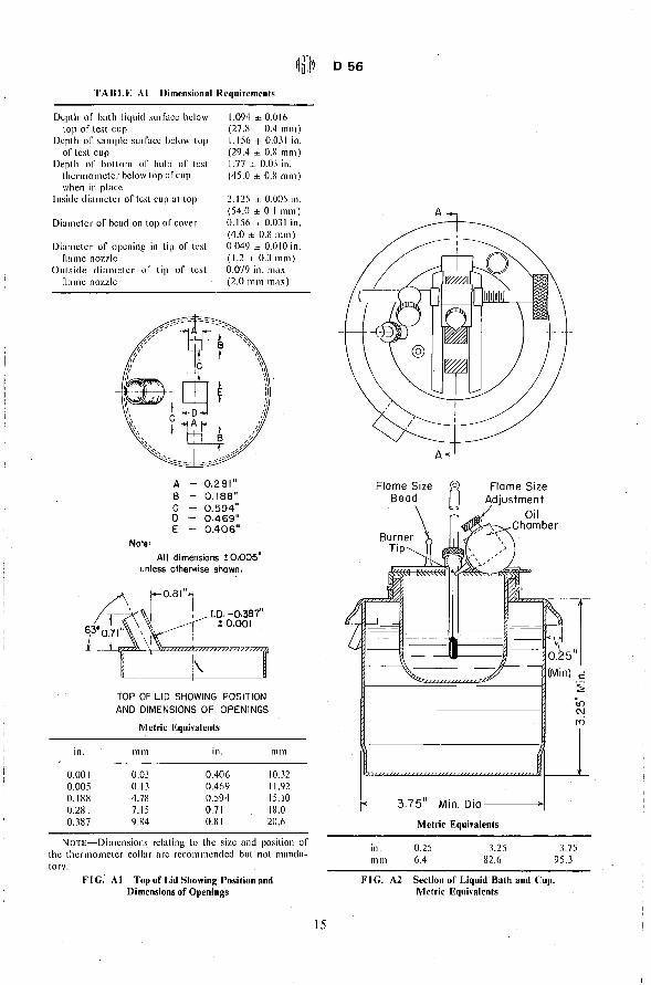
TAB LEA 1 Dimensional Requirements
Depth or bath liquid surrace below top or test cup
Depth or sample surrace helow top or test cup
Depth or hottom or hulh or test thermometer helow top or cup when in place
Inside diameter or test cup at top
Diametcr of bead on top or cover
Diameter of opening in tip or test name nozzle
Outside diameter or tip of test name nozzle
1.094 ± 0.016 (27.X ± 0.4 1111ll) 1.156 + 0.031 in. (29.4 ± 0.8 111 III ) 1.77 ± 0.03 in. (45.0 ± 0.8 111m)
2.125 ± 0.005 in. (54.0 ± 0.1 111m) 0.156 ± 0.031 in. (4.0 ± 0.8 mm) 0.049 ± 0.010 in. (1.2 ± 0.3 ml11) 0.079 in. max (2.0 mm max)
A 0.281"
in.
0.001 0.005 0.188 0.281 0.387
B 0.188" C 0.594" D 0,469" E 0.406"
Note: All dimensions! 0.005"
unless otherwise shown.
TOP OF LID SHOWING POSITION AND DIMENSIONS OF OPENINGS
Metric Equivalents
mm in.
0.03 0.406 0.13 0.469 4.78 0.594 7.15 0.71
111111
10.32 11.92 15.10 18.0
9.84 O.X I 20.6
NOTE-Dimensions relating to the size and position or the thermometer collar are recommended but not mandatory.
FIG. A 1 Top of Lid Showing Position and Dimensions of Openings
15
Flame Size Bead
Burner \ Tip
Flame Size Adjustment
Oil Chamber
Min. Dia.----~
Metric Equivalents
in. 111m
0.25 6.4
3.25 82.6
3.75 95.3
FIG. A2 Section of Liquid Bath and Cup. Metric Equivalents

r 0.21"
in.
0.002 0.21 0.28
*
mm
0.05 5.3 7.1
in.
0.34 0.385 0.68
111m
8.6 9.8
17.3
FIG. A3 Dimensions for Thermometer Ferrule (Not Mandatory).
056
in. 111111
0.06 1.5
Packing Ring (Soft Aluminum)
0.330" 00 0.284" 10 0.06" Thick
0.284 7.23
0.330 8.40
FIG. A4 Dimensions for Thermometer Packing Ring (Not Mandatory).
By publication of this standard no position is taken with respect to the validity of any patent rights in connection therewith, and the American Society for Testing and Materials does not undertake to insure anyone utilizing the standard against liability/or it~rringenient of any Leiters Patent nor assume any such liability.
16
Related Documents


![Sorption capacity of Indian coal and its variation with ... · D 3173–11]. Proximate analysis of these samples was esti-mated as per the standard method [ASTMD 3172–07a] and ultimate](https://static.cupdf.com/doc/110x72/5f2f35ec51fc955c68153d22/sorption-capacity-of-indian-coal-and-its-variation-with-d-3173a11-proximate.jpg)


