Erection Instructions Release Wind Turbine Class – K08 Type: N80/2500, N90/2300, N90/2500 K0801_14863_R00_EN Revision 00 14.08.2008 Erection Instructions Release Wind Turbine Class – K08 Type: N80/2500, N90/2300, N90/2500 Document Number: K0801_14863_R00_EN Revision: Created: 00 S. Linck/ENS E. Graumann/ENS Date: 14.08.2008 Responsible Department: Checked: Central Engineering/ENS D. Schietke/PDE Classification: NX - Nordex Internal Status: Released: FI – Final M. Franke/PDE P. Cordt/ENS AST: 3763 Replaces:

Welcome message from author
This document is posted to help you gain knowledge. Please leave a comment to let me know what you think about it! Share it to your friends and learn new things together.
Transcript
Erection Instructions Release
Wind Turbine Class – K08 Type: N80/2500, N90/2300, N90/2500
K0801_14863_R00_EN Revision 00 14.08.2008
Erection Instructions
Release
Wind Turbine Class – K08 Type: N80/2500, N90/2300, N90/2500
Document Number: K0801_14863_R00_EN
Revision: Created: 00 S. Linck/ENS E. Graumann/ENS
Date: 14.08.2008
Responsible Department: Checked: Central Engineering/ENS D. Schietke/PDE
Classification: NX - Nordex Internal
Status: Released: FI – Final M. Franke/PDE P. Cordt/ENS
AST:
3763
Replaces:

Erection Instructions Release
Wind Turbine Class – K08 Type: N80/2500, N90/2300, N90/2500
K0801_14863_R00_EN Revision 00 14.08.2008

Erection Instructions
Turbine Class K08Type: NORDEX N80/2500, N90/2300, N90/2500
K0801_014863_EN_R00_Erection_K08
Revision date: 14.08.2008
- Translation of the original operating instruction -
Document published in electronic form.
Signed original with Nordex Energy GmbH, Dept. Central Engineering.
2008 by Nordex Energy GmbH. All rights reserved.

This documentation was created taking into account the currently applicable stand-ards.
Technical modifications reserved.On account of continuous development, figures, functional steps and technical data may differ slightly.
Copyright Copyright 2008 by Nordex Energy GmbH.
This document including its presentation and content is the intellectual property of Nordex Energy GmbH. The information in this document is intended exclusively for Nordex employees and employees of trusted partners and subcontractors of Nordex Energy GmbH and must never (not even in extracts) be disclosed to third parties.
Any disclosure, duplication or translation of this document or parts thereof in printed, handwritten or electronic form without the explicit approval of Nordex Energy GmbH is explicitly prohibited.
All rights reserved.
Contact detailsFor questions relating to this documentation please contact:
Nordex Energy GmbH
Bornbarch 2
22848 Norderstedt
Germany
http://www.nordex-online.com
2008 by Nordex Energy GmbH. All rights reserved.

Table of contents K0801_014863_EN_R00_Erection_K08
1. Conventions.......................................................................................................... 7
1.1 Symbols and notices .............................................................................................. 7
1.1.1 Warning of personal injury..................................................................................... 71.1.2 Warning of material damage .................................................................................. 71.1.3 Notes and information ............................................................................................ 71.1.4 Integrated safety instructions and information........................................................ 8
1.2 Lists and steps ....................................................................................................... 8
1.3 Italic text ................................................................................................................. 8
2. General notes on erection ................................................................................... 9
2.1 Tools, resources and consumables...................................................................... 10
2.2 Referenced documents ........................................................................................ 11
2.2.1 Documents on occupational safety ...................................................................... 112.2.2 Standards ............................................................................................................. 112.2.3 Erection documents.............................................................................................. 112.2.4 Assembly documents ........................................................................................... 122.2.5 Manufacturer documents...................................................................................... 122.2.6 Factory standards................................................................................................. 122.2.7 Drawings .............................................................................................................. 122.2.8 Circuit diagrams ................................................................................................... 132.2.9 Other documents.................................................................................................. 132.2.10 Options ................................................................................................................. 13
2.3 Abbreviations and terms....................................................................................... 14
3. Tower erection.................................................................................................... 15
3.1 Attaching and unloading the tower segments ...................................................... 15
3.1.1 Attach the tower segments................................................................................... 163.1.2 Intermediate storage of the tower segments ........................................................ 19
3.2 Attaching and unloading the bottom box .............................................................. 20
3.2.1 Attach the bottom box .......................................................................................... 203.2.2 Intermediate storage of the bottom box................................................................ 21
3.3 Preparing the foundation ...................................................................................... 22
3.4 Installing the transformer in the tower .................................................................. 23
3.5 Erecting the bottom tower segment...................................................................... 25
3.5.1 Preparatory work .................................................................................................. 253.5.2 Erect the bottom tower segment .......................................................................... 273.5.3 Guide the bottom tower segment from the inside................................................. 283.5.4 Measure the bottom tower segment..................................................................... 293.5.5 Ground the bottom tower segment....................................................................... 323.5.6 Enter the turbine components .............................................................................. 33
3.6 Erecting the remaining tower segments ............................................................... 36
Erection Instructions Turbine Class K08 Seite 3 von 6
K0801_014863_EN_R00_Erection_K08 Table of contents
3.6.1 Preparatory work on the erected tower segment ................................................. 363.6.2 Prepare the tower segment to be erected ............................................................ 373.6.3 Erect the tower segment ...................................................................................... 393.6.4 Connect the tower segments................................................................................ 403.6.5 Ground the tower flanges ..................................................................................... 423.6.6 Fit the external screw connections ....................................................................... 433.7 Measuring the complete tower ............................................................................. 45
3.8 Tightening the tower screw connections .............................................................. 46
3.9 Fitting the fall arrest rope...................................................................................... 47
3.10 Screw connections ............................................................................................... 48
3.10.1 Screw connections for foundations ...................................................................... 493.10.2 Screw connections for 3-part towers .................................................................... 493.10.3 Screw connections for 3-part towers .................................................................... 503.10.4 Screw connections for 4-part towers .................................................................... 503.10.5 Screw connections for 5-part towers .................................................................... 523.10.6 Screw connections for 6-part towers .................................................................... 52
4. Tower completion............................................................................................... 55
4.1 Preserving the foundation screw connection........................................................ 55
4.2 Assembling the service lift .................................................................................... 56
4.3 Fitting the insulation for the bottom box ............................................................... 57
4.4 Fitting the cooling systems of the bottom box ...................................................... 58
4.4.1 Air cooling with cooling unit .................................................................................. 584.4.2 Water cooling system for the converter ................................................................ 58
4.5 Sealing the tower.................................................................................................. 61
4.6 Fitting the fire extinguishers ................................................................................. 62
4.7 Attaching the warning signs ................................................................................. 62
4.8 Storing the rescue and abseiling equipment ........................................................ 63
5. Drive train assembly .......................................................................................... 65
5.1 Preparing the machine frame ............................................................................... 65
5.2 Attaching and lifting the drive train ....................................................................... 65
5.3 Placing the drive train onto the machine frame .................................................... 68
5.4 Jacking the drive train apart ................................................................................. 72
5.5 Screwing the drive train to the machine frame ............................................... 735.6 Fitting the safety rope........................................................................................... 75
5.7 Completing the drive train assembly .................................................................... 76
6. Nacelle erection.................................................................................................. 79
Seite 4 von 6 Turbine Class K08 Erection Instructions
Table of contents K0801_014863_EN_R00_Erection_K08
6.1 Preparing the nacelle ........................................................................................... 79
6.1.1 Opening the nacelle roof ...................................................................................... 796.1.2 Fitting the lightning arrester .................................................................................. 806.1.3 Fitting the air scoop .............................................................................................. 826.1.4 Fitting and connecting the obstacle lights (optional) ............................................ 846.1.5 Fitting and connecting the wind sensors .............................................................. 846.1.6 Fitting the safety rail ............................................................................................. 886.1.7 Connecting the brake motor control box .............................................................. 89
6.2 Installing the nacelle on the tower ........................................................................ 90
6.2.1 Preparing the nacelle without the drive train ........................................................ 916.2.2 Preparing the nacelle with the drive train ............................................................. 95
7. Nacelle completion............................................................................................. 99
7.1 Completing the hydraulic system ......................................................................... 99
7.2 Inspecting the rotor brake at the rotor brake disk............................................... 100
7.3 Assembling the individual components .............................................................. 101
7.3.1 Assemble the yaw drive cam limit switch ........................................................... 1017.3.2 Assemble the automatic rotor bearing lubrication system.................................. 1027.3.3 Seal the lifting lugs ............................................................................................. 1037.3.4 Fit the oil overflow .............................................................................................. 1037.3.5 Fit the fire extinguisher ....................................................................................... 104
7.4 Assembling the coupling .................................................................................... 104
7.4.1 Link coupling ...................................................................................................... 1047.4.2 Multi-disk coupling.............................................................................................. 105
7.5 Aligning the generator ........................................................................................ 108
7.6 Checking the generator alignment ..................................................................... 109
7.6.1 Fixturlaser alignment system.............................................................................. 1097.6.2 Set dial gage ...................................................................................................... 112
7.7 Adjusting and screwing on the generator elastomer bearings ........................... 115
7.8 Completing the gearbox cooling circuit .............................................................. 118
7.9 Assembling the guard for the coupling ............................................................... 119
7.10 Commissioning and testing the rotor brake........................................................ 121
7.11 Completing the generator cooling circuit ............................................................ 124
7.12 Securing the on-board crane.............................................................................. 126
8. Rotor erection................................................................................................... 127
8.1 Unloading and preassembling the rotor hub ...................................................... 127
8.1.1 Position the rotor hub ......................................................................................... 1288.1.2 Prepare the pitch bearing ................................................................................... 1298.1.3 Assemble the hub cage...................................................................................... 130
Erection Instructions Turbine Class K08 Seite 5 von 6

K0801_014863_EN_R00_Erection_K08 Table of contents
8.2 Star assembly..................................................................................................... 1318.2.1 Attach the rotor blades ....................................................................................... 1318.2.2 Prepare and install the rotor blades ................................................................... 1328.2.3 Connect the pitch auxiliary box .......................................................................... 1358.2.4 Move the rotor blade into the 90° position (feathering position) ......................... 1368.2.5 Install rotor blades 2 and 3 ................................................................................. 1378.2.6 Install the star ..................................................................................................... 1388.2.7 Attach the rotor hub............................................................................................ 1408.2.8 Attach the rotor blade ......................................................................................... 1408.2.9 Lift and assemble the star .................................................................................. 142
8.3 Single blade assembly ....................................................................................... 147
8.3.1 Assemble the rotor hub ...................................................................................... 1478.3.2 Assemble the geared motor ............................................................................... 1488.3.3 Install the rotor blades ........................................................................................ 149
8.4 Final work ........................................................................................................... 151
9. Electrical installation ....................................................................................... 153
9.1 Notes .................................................................................................................. 153
9.2 Connecting the cables in the rotor hub............................................................... 154
9.3 Installing power and ground cables.................................................................... 155
9.3.1 Power cable layout ............................................................................................. 1559.3.2 Routing the power cables................................................................................... 1559.3.3 Routing the power cables in the tower ............................................................... 156
9.4 Ground cables .................................................................................................... 165
9.4.1 Nacelle ............................................................................................................... 1659.4.2 Loop ................................................................................................................... 1659.4.3 Tower ................................................................................................................. 1669.4.4 Foundation ......................................................................................................... 166
9.5 Line-side cable connection in the bottom box .................................................... 166
9.6 Installing the control cables ................................................................................ 169
9.7 Final cable work ................................................................................................. 170
10. Final work.......................................................................................................... 171
10.1 Cleaning the turbine ........................................................................................... 171
10.2 Preservation ....................................................................................................... 171
10.2.1 Repairing preservations ..................................................................................... 17210.2.2 Preserving the yaw bearings .............................................................................. 172
10.3 Final inspection .................................................................................................. 172
10.4 Checking the documentation.............................................................................. 173
10.5 Exiting the WT .................................................................................................... 173
Seite 6 von 6 Turbine Class K08 Erection Instructions
Erection Instructions K0801_014863_EN_R00_Erection_K08
1. Conventions
1.1 Symbols and notices
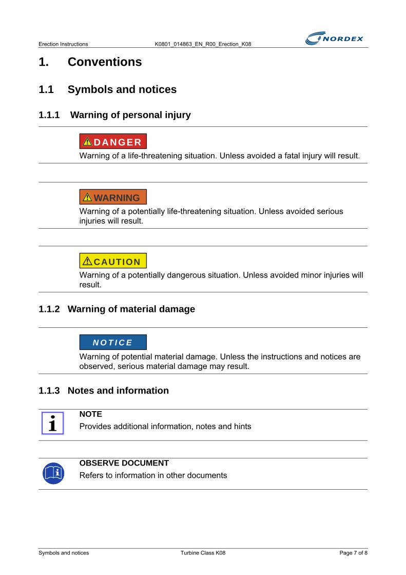
1.1.1 Warning of personal injury
1.1.2 Warning of material damage
1.1.3 Notes and information
Warning of a life-threatening situation. Unless avoided a fatal injury will result.
Warning of a potentially life-threatening situation. Unless avoided serious injuries will result.
Warning of a potentially dangerous situation. Unless avoided minor injuries will result.
Warning of potential material damage. Unless the instructions and notices are observed, serious material damage may result.
NOTEProvides additional information, notes and hints
OBSERVE DOCUMENTRefers to information in other documents
DANGER
WARNING
CAUTION
N O T I C E
Symbols and notices Turbine Class K08 Page 7 of 8

K0801_014863_EN_R00_Erection_K08 Erection Instructions
1.1.4 Integrated safety instructions and informationInformation and safety notices integrated into the text. Indicated by the signal word (danger/caution/warning/notice) in bold.
Example: Integrated safety instructions
Caution: To prevent damage to the paintwork, the segments must not touch the ground.
1.2 Lists and steps■ Describes a step to be executed► Describes the result of a step (action result)
● Describes a simple list (e.g. preconditions)- Describes a subordinated list
1.3 Italic textIdentification of proper names (e.g. manufacturer name, document title).
Page 8 of 8 Turbine Class K08 Lists and steps

Erection Instructions K0801_014863_EN_R00_Erection_K08
2. General notes on erectionThe documents contain all work steps for erecting the wind turbines N80/2500, N90/2300, N90/2500.
A prerequisites for carrying out the work steps described here is the observance of all national and Nordex-defined safety relevant specifications
Documentation of erection work
Specialized personnel and unauthorized individuals
NOTEDocument all necessary details and work steps in the Erection Report (K202_601_IN).
Submit the Erection Report to Nordex immediately after erection has been completed.
NOTEAlways document photos of damage and repairs together with a scale!
OBSERVE DOCUMENTObserve the manufacturer and vendor documentation (see "References")
FOR SPECIALIZED PERSONNEL ONLYThe tasks described in this document must only be carried out by industry-typical appropriately qualified specialized personnel.
NO ACCESS FOR UNAUTHORIZED INDIVIDUALSThroughout the erection work no unauthorized individuals may be present on the site.
Cordon off the construction site adequately and place warning signs.
Should unauthorized individuals be present within the construction site in spite of barriers, stop the work and direct the individuals to leave the construction site!
DANGER
DANGER
Turbine Class K08 Page 9 of 14

K0801_014863_EN_R00_Erection_K08 Erection Instructions
2.1 Tools, resources and consumables
Tools
All necessary tools are in 2 containers.
These include:
● Diesel generator
● Cables and adapters for power supply
● Workbench
● Access ladder
● Lamps
● Special tools (ITH, Hytorc, wrenches)
● Lifting tackle
● Webbing slings and chain slings
● Guide pins and guide ropes
In countries with 110V grid supply 2 isolating transformers with corresponding sockets are additionally supplied:
● 1 transformer as mounted version with protective tread (next to the top box)
● 1 transformer as portable version for the tower (siehe Abb.1)
Abb. 1 Portable isolation transformer 110V
Resources and consumables
All necessary resources and consumables are in an additional container.
These include:
● Tower screws
● Cleaning agents
● Cleaning cloths
● Paint in different colors
Page 10 of 14 Turbine Class K08 Tools, resources and consumables
Erection Instructions K0801_014863_EN_R00_Erection_K08
● Preservatives
● Small parts
2.2 Referenced documents
2.2.1 Documents on occupational safety
2.2.2 Standards
2.2.3 Erection documents
NOTEAll documents listed here must be available at the time of the respective erection task.
The documents must have been read and understood by all individuals involved in the erection.
The safety instructions in the individual documents must be observed in particular
Document no. Title
NX_HS_0002_EN Instructions for the Execution of all Work Steps and the Behavior in and near Wind Turbines (Nordex Employees)
NX_HS_0004_EN Instructions for the Execution of all Work Steps and the Behavior in and near Wind Turbines (Subcontractors)
NALL01_011010_EN Safety Manual
Document no. TitleIEC 60364 Erection of Low Voltage Systems
DIN VDE 0101/HD 637 S1
High Current Systems with Nominal Alternating Voltages above 1kV
DIN EN 50110 Operation of Electrical Systems
DIN EN 61238 Compression Joints
Document no. TitleK0801_011163_EN Screw Connections for K08 Erection
K202_601_IN Erection Report N80/2500, N90/2300, N90/2500, N100/2500
Referenced documents Turbine Class K08 Page 11 of 14

K0801_014863_EN_R00_Erection_K08 Erection Instructions
2.2.4 Assembly documents
2.2.5 Manufacturer documents
2.2.6 Factory standards
2.2.7 Drawings
Document no. TitleI201_773_EN General Assembly Information
I202_723_DE Assembly of Air conditioner/heater on the Bottom Box
I403_077_DE Assembly of Drainage Hose at the Converter
I403_083_DE Assembly of Safety Rope System
K403_083_DE Assembly Report Safety Rope System
I202_721_DE Assembly of External Platform
Document no. TitleI210_012_X_EN Shaft Alignment with Fixtur Laser System
HACA_MA_5017d_EN Fall Arrest Rail Assembly Instructions
I201_791_X_DE ESM Gearbox Bearing Assembly Instructions
I210_004_X_IN ITH Screw Tightening Cylinder Operating Instructions
Theodolite Operating Instructions
Note: X = project-specific variable
Document no. TitleF010_001_EN Mounting and Documenting srv-bolts NALL
F010_002_DE Wind Turbine without Grid Connection or with Locked Drive Train
F220_100_DE Installing the Service Lift
Document no. Title03803-1010855 Centering Pin Drawing
801_02_00512 Tower Base Cooling System Drawing
02180-1002387 Gearbox Clamps Drawing
01220-1004121 Drive Train on Transport Rack Drawing, N80/2500, N90/2300
Page 12 of 14 Turbine Class K08 Referenced documents
Erection Instructions K0801_014863_EN_R00_Erection_K08
2.2.8 Circuit diagrams
2.2.9 Other documents
2.2.10 Options
01220-1009157 Drive Train on Transport Frame Drawing, N90/2500
801_06_00005 Gearbox Assembly Drawing
801_06_00003 Rotor Bearing Housing Assembly Drawing
Document no. Title23-0715 Circuit Diagram Brake Motor Control Box N80, N90, N100
23-05xx_Nx0_NC2_BFU Circuit Diagram Switch/Converter Cabinet (Bottom)
23-05xx_Nx0_NC2_PI Circuit Diagram Pitch
23-05xx_Nx0_NC2_TB Circuit Diagram Top Box
Document no. TitleI401_689_EN Screw Connection Color Legend
K201_411_DE Drive Train Test Run Inspection Report
I501_050_A01_EN WT Signs
N80-3-transport-de Sales files; Dimensions and Weights
Document no. TitleCMS
Obstacle lights
Document no. Title
Referenced documents Turbine Class K08 Page 13 of 14

K0801_014863_EN_R00_Erection_K08 Erection Instructions
2.3 Abbreviations and terms
Abbreviation/term Definition
Bottom box Control cabinet in the tower base, including converter
CMS Condition Monitoring System
DIBt *) Deutsches Institut für Bautechnik
flZnncl Zinc flake coating (Delta-Stone-Seal)
FU Frequency converter
GL *) Germanischer Lloyd
HV High-strength
IBN Commissioning
IEC *) International Electrotechnical Commission
Loop Flexible cable loop in the tower top to enable the rotation of the nacelle
Luv Side facing the wind
LVB Load-spreading plate
PG Reinforced thread
EBR Equipotential bonding bar
PPE Personal protective equipment
A/F Wrench size
Top box Switch cabinet in the nacelle
tZn Hot galvanizing
Compressed cable
Small outside diameter, individual wires do not have a perfectly round profile, signs of rolling can be seen on the outside, rather the shape of a massive round conductor
WT Wind turbine
*) Note: The abbreviations DIBt, GL and IEC are certificates determining in which wind zones a tower may be erected. DIBt only applies in Germany; GL and IEC only apply abroad.
Page 14 of 14 Turbine Class K08 Abbreviations and terms

Erection Instructions K0801_014863_EN_R00_Erection_K08
3. Tower erectionTo erect the tower the following steps must be carried out:
Preparatory work
● Attaching and unloading the tower segments
● Attaching and unloading the bottom box
● Preparing the foundation
● Installing the transformer in the tower
Tower erection
● Erecting the bottom tower segment- Measure the bottom tower segment- Ground the bottom tower segment- Enter the turbine components
● Erecting the remaining tower segments- Preparatory work on the erected tower segment- Connect the tower segments- Ground the tower flanges- Fit the external screw connections
Final work
● Measuring the complete tower
● Tightening the tower screw connections
3.1 Attaching and unloading the tower segmentsThe tower is delivered in individual segments with 1 truck each.
Delivery condition
● Access ladder, platforms and lamps are already fitted to the tower segments.
OBSERVE DOCUMENTComponent weights and dimensions: http://sales.nordex-online.com/N80/N80-3-transport-de.pdf
NOTEThe time sequence of the work steps described here is project-specific.
Attaching and unloading the tower segments Turbine Class K08 Page 15 of 54

K0801_014863_EN_R00_Erection_K08 Erection Instructions
● Cables and service lift are already pre-installed in the tower segments
● 1 Every tower segment is covered by 1 tarpaulin on the front and the back.
Work steps to be performed
■ Remove the tarpaulins
■ Return the tarpaulins to the tower manufacturer
■ Check the tower segments for completeness and damageNote: If the tower segments are incomplete or damaged, complete the Non-Conformity Report and send it to the project manager
3.1.1 Attach the tower segments
Attachment points
● The small crane is attached to the top of the tower segment with 2 lifting tackles (see Fig. 4)
● The small crane is attached to the bottom of the tower segment with 1 lifting tackle (see Fig. 5)
Trucks with hydraulic holding devices
If the trucks are equipped with hydraulic holding devices, the lifting tackles cannot be fitted to the top end of the tower segment.
■ Lower the top end of the tower segment onto the prepared surface with the hydraulic holding device
■ Detach the tower segment from the hydraulic holding device
RISK OF TOPPLING AND ROLLING OFFOn a sloping ground the truck and tower segment can topple, slide or roll off.
Place the truck and tower segment onto a firm surface.
The firm surface must be on a firm level floor.
PAINT DAMAGELowering can cause paint damage in the tower segment.
Before lowering the tower segment place a piece of clean textile (e.g. carpet) onto the firm surface.
WARNING
N O T I C E
Page 16 of 54 Turbine Class K08 Attaching and unloading the tower segments
Erection Instructions K0801_014863_EN_R00_Erection_K08
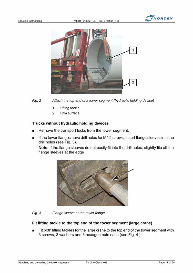
Fig. 2 Attach the top end of a tower segment (hydraulic holding device)
1. Lifting tackle2. Firm surface
Trucks without hydraulic holding devices
■ Remove the transport locks from the tower segment.
■ If the tower flanges have drill holes for M42 screws, insert flange sleeves into the drill holes (see Fig. 3). Note: If the flange sleeves do not easily fit into the drill holes, slightly file off the flange sleeves at the edge
Fig. 3 Flange sleeve at the tower flange
Fit lifting tackle to the top end of the tower segment (large crane)
■ Fit both lifting tackles for the large crane to the top end of the tower segment with 3 screws, 3 washers and 3 hexagon nuts each (see Fig. 4 ).
2
1
Attaching and unloading the tower segments Turbine Class K08 Page 17 of 54
K0801_014863_EN_R00_Erection_K08 Erection Instructions
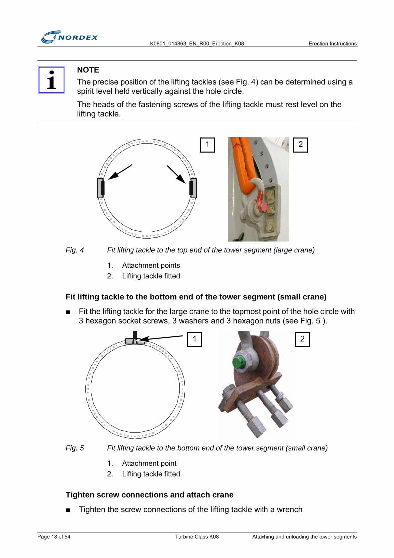
Fig. 4 Fit lifting tackle to the top end of the tower segment (large crane)
1. Attachment points2. Lifting tackle fitted
Fit lifting tackle to the bottom end of the tower segment (small crane)
■ Fit the lifting tackle for the large crane to the topmost point of the hole circle with 3 hexagon socket screws, 3 washers and 3 hexagon nuts (see Fig. 5 ).
Fig. 5 Fit lifting tackle to the bottom end of the tower segment (small crane)
1. Attachment point2. Lifting tackle fitted
Tighten screw connections and attach crane
■ Tighten the screw connections of the lifting tackle with a wrench
NOTEThe precise position of the lifting tackles (see Fig. 4) can be determined using a spirit level held vertically against the hole circle.
The heads of the fastening screws of the lifting tackle must rest level on the lifting tackle.
21
21
Page 18 of 54 Turbine Class K08 Attaching and unloading the tower segments

Erection Instructions K0801_014863_EN_R00_Erection_K08
■ Attach the large crane with 2 webbing slings (load capacity 40t each) and 2 shackles (load capacity 35t each)
■ Attach the small crane with 1 webbing sling (load capacity 40t) 1 and a shackle (load capacity 35t).
Fig. 6 Tower segment attached
1. Top end of the tower segment (large crane) 2. Bottom end of the tower segment (small crane)
Hydraulic holding devices only
■ Allow small crane to pick up the load
■ Detach the bottom part of the tower segment from the hydraulic holding device
3.1.2 Intermediate storage of the tower segments
RISK OF ROLLING OFFTower segments can roll off.
Place the tower segments on a firm surface.
The firm surface must be on a firm level floor.
1 2
WARNING
Attaching and unloading the tower segments Turbine Class K08 Page 19 of 54
K0801_014863_EN_R00_Erection_K08 Erection Instructions
Work steps to be performed
■ Prepare a suitable assembly locationNote: Use squared timbers/supports from the transport vehicle.
■ Attach the tower segment (see "Attach the tower segments" page 16)
■ Lift the tower segment and place it onto the prepared assembly location
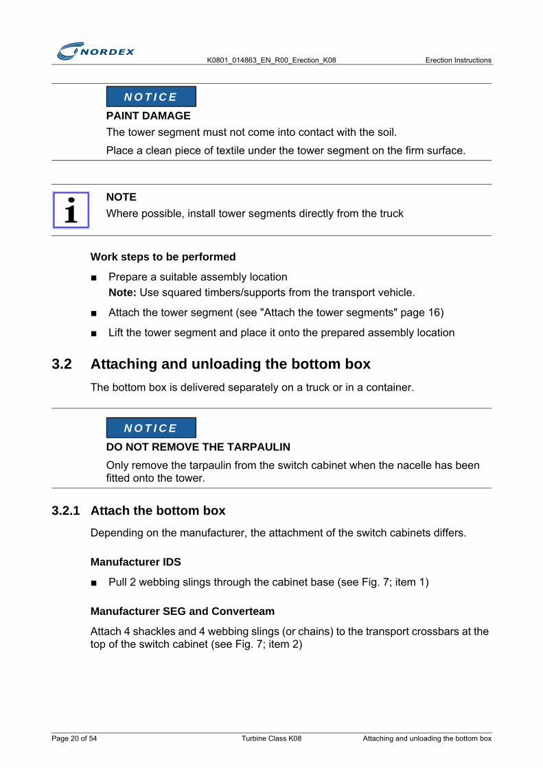
3.2 Attaching and unloading the bottom boxThe bottom box is delivered separately on a truck or in a container.
3.2.1 Attach the bottom boxDepending on the manufacturer, the attachment of the switch cabinets differs.
Manufacturer IDS
■ Pull 2 webbing slings through the cabinet base (see Fig. 7; item 1)
Manufacturer SEG and Converteam
Attach 4 shackles and 4 webbing slings (or chains) to the transport crossbars at the top of the switch cabinet (see Fig. 7; item 2)
PAINT DAMAGEThe tower segment must not come into contact with the soil.
Place a clean piece of textile under the tower segment on the firm surface.
NOTEWhere possible, install tower segments directly from the truck
DO NOT REMOVE THE TARPAULINOnly remove the tarpaulin from the switch cabinet when the nacelle has been fitted onto the tower.
N O T I C E
N O T I C E
Page 20 of 54 Turbine Class K08 Attaching and unloading the bottom box
Erection Instructions K0801_014863_EN_R00_Erection_K08
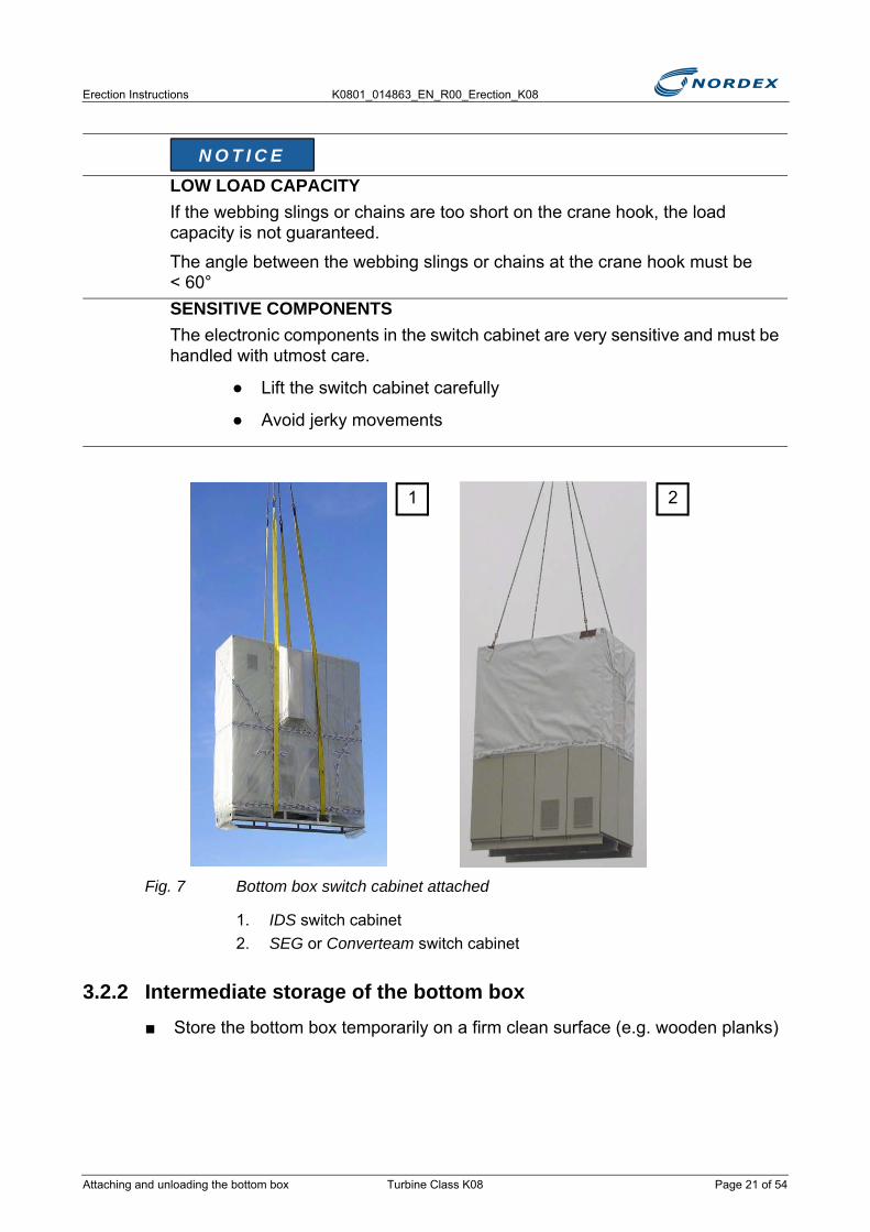
Fig. 7 Bottom box switch cabinet attached
1. IDS switch cabinet2. SEG or Converteam switch cabinet
3.2.2 Intermediate storage of the bottom box■ Store the bottom box temporarily on a firm clean surface (e.g. wooden planks)
LOW LOAD CAPACITYIf the webbing slings or chains are too short on the crane hook, the load capacity is not guaranteed.
The angle between the webbing slings or chains at the crane hook must be < 60°SENSITIVE COMPONENTSThe electronic components in the switch cabinet are very sensitive and must be handled with utmost care.
● Lift the switch cabinet carefully
● Avoid jerky movements
N O T I C E
1 2
Attaching and unloading the bottom box Turbine Class K08 Page 21 of 54
K0801_014863_EN_R00_Erection_K08 Erection Instructions
3.3 Preparing the foundationThe foundation, including the conduits, load-spreading plate and grouting mortar, is complete and fully level. The cabling through the foundation may also have already been routed.
Check the foundation
■ Check whether the foundation has damage or cracks- If damage or cracks are present, repair the damage- If a repair is not possible on site, complete the Non-Conformity Report and
send it to the project manager
■ Check that the anchor bolts are undamaged
■ Make all required tools and materials as well as resources, power or compressed air ready from the erection container
Work steps to be performed
■ Shorten the conduits protruding from the top of the foundation to approx. 100mm above the foundation.Caution: Do not cut flush with the foundation! Shorten each conduit individually.
■ Check the position of the conduits in relation to the tower door and mark the future position of the tower door (usually towards the access roads)
■ Thoroughly clean the load-spreading plate:- Brush out the gaps between the anchor bolts - Clean the load-spreading plate with additional means in case of stronger
contamination
■ Clean the anchor bolt threads with a wire brush
■ Lubricate the anchor bolt threads completely with Molykote G-Rapid Plus
NOTECondition for erecting the first tower segment:
Acceptance Report of the foundation (K202_032_EN) has been checked by the project/site manager.
• The foundation has been released for erection by the project/site manager• The casting of the foundation was at least 28 days ago• The processing of the grouting mortar was at least 24 hours ago
Page 22 of 54 Turbine Class K08 Preparing the foundation

Erection Instructions K0801_014863_EN_R00_Erection_K08
Fig. 8 Foundation screw connection (assembly position)
1. Anchor bolts2. Load-spreading plate3. Hexagon nut4. Spherical washer5. Conical seat
■ Make hexagon nuts, spherical washers and conical seats ready in the assembly positionNote: In all towers spherical washers are always used (conical seat/spherical washer DIN 6319).
■ Lubricate the contact surfaces of all top washers with Molykote G-Rapid Plus Caution: Do not lubricate the hexagon nuts!
3.4 Installing the transformer in the tower
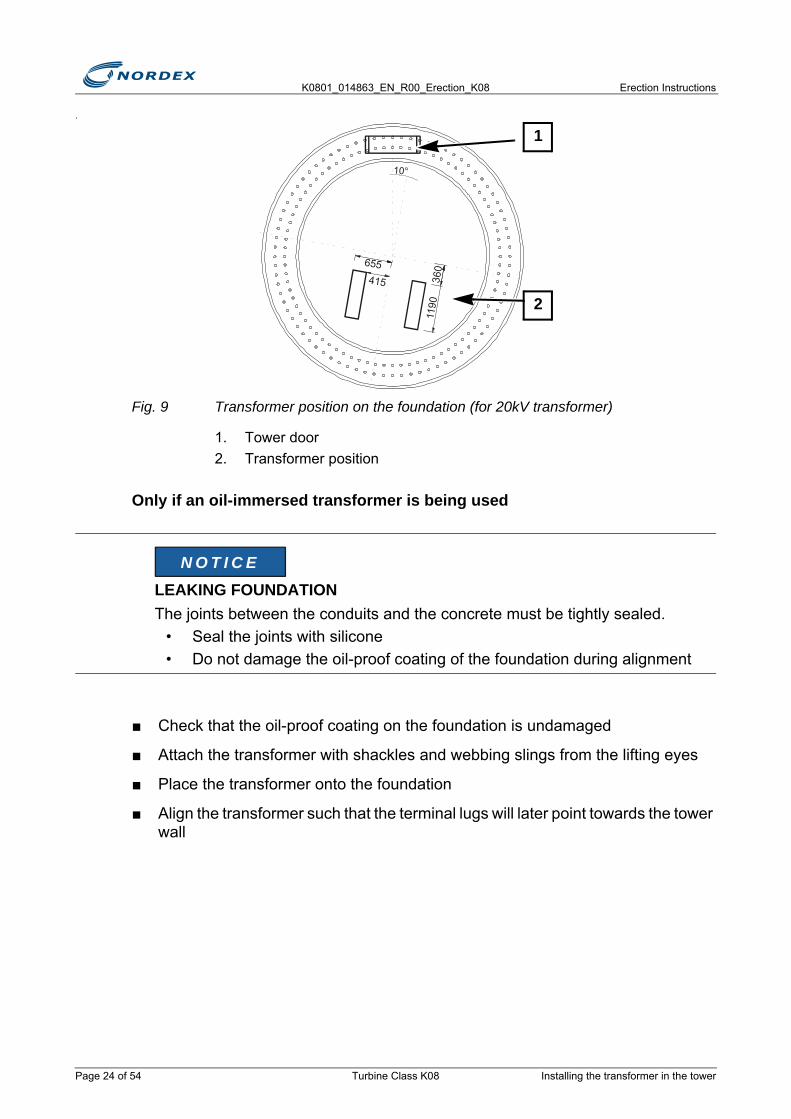
■ Mark the position of the transformer on the foundation (starting from the door position) (see Fig. 9)
NOTEFirst place the transformer onto the tower segment, then erect the bottom tower segment
2
3 4 5
1
Installing the transformer in the tower Turbine Class K08 Page 23 of 54
K0801_014863_EN_R00_Erection_K08 Erection Instructions
.
Fig. 9 Transformer position on the foundation (for 20kV transformer)
1. Tower door2. Transformer position
Only if an oil-immersed transformer is being used
■ Check that the oil-proof coating on the foundation is undamaged
■ Attach the transformer with shackles and webbing slings from the lifting eyes
■ Place the transformer onto the foundation
■ Align the transformer such that the terminal lugs will later point towards the tower wall
LEAKING FOUNDATIONThe joints between the conduits and the concrete must be tightly sealed.
• Seal the joints with silicone• Do not damage the oil-proof coating of the foundation during alignment
1190
360
415
655
10°
1
2
N O T I C E
Page 24 of 54 Turbine Class K08 Installing the transformer in the tower
Erection Instructions K0801_014863_EN_R00_Erection_K08
3.5 Erecting the bottom tower segment
3.5.1 Preparatory work■ Check the tower interiors (cable holders, access ladder, platforms and lighting)
for completeness
■ Check the tower interiors randomly for correct attachment
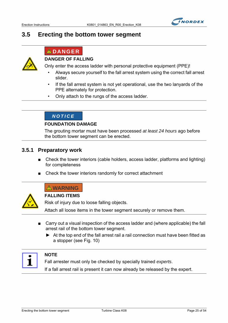
■ Carry out a visual inspection of the access ladder and (where applicable) the fall arrest rail of the bottom tower segment.► At the top end of the fall arrest rail a rail connection must have been fitted as
a stopper (see Fig. 10)
DANGER OF FALLINGOnly enter the access ladder with personal protective equipment (PPE)!
• Always secure yourself to the fall arrest system using the correct fall arrest slider.
• If the fall arrest system is not yet operational, use the two lanyards of the PPE alternately for protection.
• Only attach to the rungs of the access ladder.
FOUNDATION DAMAGEThe grouting mortar must have been processed at least 24 hours ago before the bottom tower segment can be erected.
FALLING ITEMSRisk of injury due to loose falling objects.
Attach all loose items in the tower segment securely or remove them.
NOTEFall arrester must only be checked by specially trained experts.
If a fall arrest rail is present it can now already be released by the expert.
DANGER
N O T I C E
WARNING
Erecting the bottom tower segment Turbine Class K08 Page 25 of 54
K0801_014863_EN_R00_Erection_K08 Erection Instructions
Fig. 10 Rail connector at the fall arrest rail
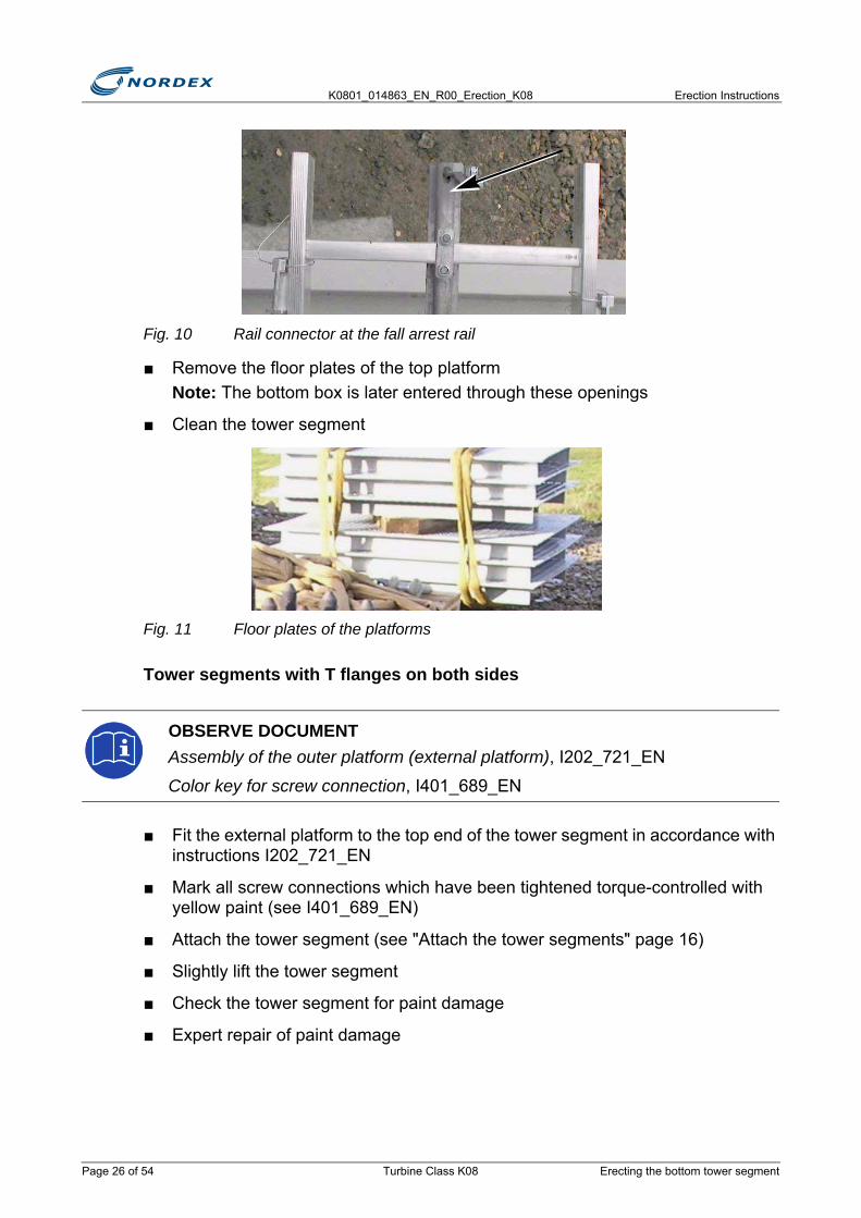
■ Remove the floor plates of the top platformNote: The bottom box is later entered through these openings
■ Clean the tower segment
Fig. 11 Floor plates of the platforms
Tower segments with T flanges on both sides
■ Fit the external platform to the top end of the tower segment in accordance with instructions I202_721_EN
■ Mark all screw connections which have been tightened torque-controlled with yellow paint (see I401_689_EN)
■ Attach the tower segment (see "Attach the tower segments" page 16)
■ Slightly lift the tower segment
■ Check the tower segment for paint damage
■ Expert repair of paint damage
OBSERVE DOCUMENTAssembly of the outer platform (external platform), I202_721_EN
Color key for screw connection, I401_689_EN
Page 26 of 54 Turbine Class K08 Erecting the bottom tower segment

Erection Instructions K0801_014863_EN_R00_Erection_K08
3.5.2 Erect the bottom tower segment
■ Erect the tower segment (see Fig. 12):- The large crane pulls up - The small crane follows with the tower segment until the tower segment is
suspended vertically
■ When the tower segment is suspended vertically, relieve the load on the small crane
Fig. 12 Erect the tower segment
■ Detach the lifting tackle from the tower flange
■ Enquire the weight of the tower segment from the crane operator
■ Note the weight of the tower segment in the Erection Report (K202_601_IN)
■ Apply 1 bead of silicone between the anchor bolts
FALLING ITEMSDuring the rotation of the tower segment loose items can fall out of the tower segment. Nobody must be present underneath the tower segment during erection.SUSPENDED LOADWork below the tower segment must only be carried out after having consulted the site manager, the crane operators and a safety person.
WARNING
Erecting the bottom tower segment Turbine Class K08 Page 27 of 54
K0801_014863_EN_R00_Erection_K08 Erection Instructions
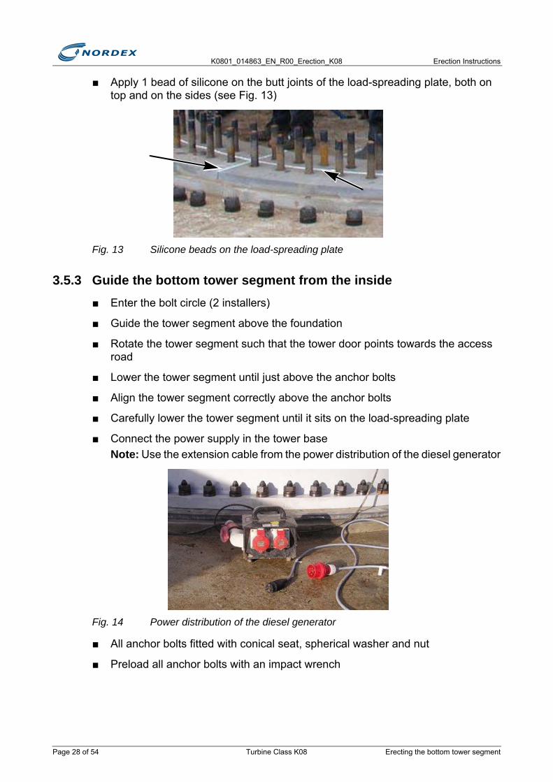
■ Apply 1 bead of silicone on the butt joints of the load-spreading plate, both on top and on the sides (see Fig. 13)
Fig. 13 Silicone beads on the load-spreading plate
3.5.3 Guide the bottom tower segment from the inside■ Enter the bolt circle (2 installers)
■ Guide the tower segment above the foundation
■ Rotate the tower segment such that the tower door points towards the access road
■ Lower the tower segment until just above the anchor bolts
■ Align the tower segment correctly above the anchor bolts
■ Carefully lower the tower segment until it sits on the load-spreading plate
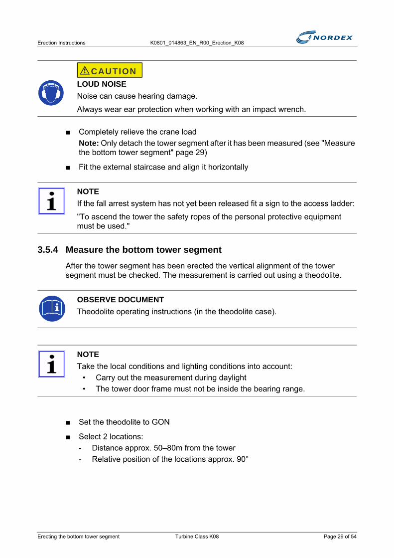
■ Connect the power supply in the tower baseNote: Use the extension cable from the power distribution of the diesel generator
Fig. 14 Power distribution of the diesel generator
■ All anchor bolts fitted with conical seat, spherical washer and nut
■ Preload all anchor bolts with an impact wrench
Page 28 of 54 Turbine Class K08 Erecting the bottom tower segment
Erection Instructions K0801_014863_EN_R00_Erection_K08
■ Completely relieve the crane loadNote: Only detach the tower segment after it has been measured (see "Measure the bottom tower segment" page 29)
■ Fit the external staircase and align it horizontally
3.5.4 Measure the bottom tower segmentAfter the tower segment has been erected the vertical alignment of the tower segment must be checked. The measurement is carried out using a theodolite.
■ Set the theodolite to GON
■ Select 2 locations:- Distance approx. 50–80m from the tower- Relative position of the locations approx. 90°
LOUD NOISENoise can cause hearing damage.
Always wear ear protection when working with an impact wrench.
NOTEIf the fall arrest system has not yet been released fit a sign to the access ladder:
"To ascend the tower the safety ropes of the personal protective equipment must be used."
OBSERVE DOCUMENTTheodolite operating instructions (in the theodolite case).
NOTETake the local conditions and lighting conditions into account:
• Carry out the measurement during daylight• The tower door frame must not be inside the bearing range.
CAUTION
Erecting the bottom tower segment Turbine Class K08 Page 29 of 54

K0801_014863_EN_R00_Erection_K08 Erection Instructions
Fig. 15 Measuring the tower segment
1. Location 12. Location 23. Door entry (2 variants)4. Measuring points 1-5
Measuring point 1 (= measuring point 5)
■ Position the theodolite at location 1.
■ Take a bearing of measuring point 1
■ Set the horizontal angle indicated on the theodolite to 0
■ Note the vertical angle of the tower segment in the Erection Report (K202_601_IN)
Measuring point 2
■ Starting from measuring point 1 change the height to measuring point 2
■ Note the vertical angle
■ Rotate horizontally up to measuring point 2
■ Note the degree value indicated on the theodolite as value 1 Measuring point 3
■ At the same height as measuring point 2 take a bearing of measuring point 3
■ Set the horizontal angle to 0
■ Lower the crosshair up to the vertical angle determined at measuring point 1
1 + 5
2
4
3
50–80 m50
–80
m
90°
1
3
2 4
Page 30 of 54 Turbine Class K08 Erecting the bottom tower segment

Erection Instructions K0801_014863_EN_R00_Erection_K08
Measuring point 4
■ Do not change the height
■ Rotate up to measuring point 4
■ Note the degree value indicated on the theodolite as value 2 in the Erection Report (K202_601_IN)
Measuring point 5
■ Check that point 1 and 5 matchNote: The deviation of the horizontal angle must not be greater than 0.001GON. If the deviation is greater, repeat the measurement
■ Half the difference between reading 1 and 2 (smaller value from the larger value)Note: The value calculated in this way is the vertical deviation of the tower axis in [°]. This value must be converted to [mm].
Convert deviation to [mm]
■ Hold a ruler/folding meter horizontally against the tower (see Fig. 16).
Fig. 16 Convert the deviation of the tower segment to [mm]
1. Tower segment2. Theodolite3. Ruler/folding meter
■ Take a bearing of a point on the ruler/folding meter (even number or 0)
■ Set the horizontal angle of the theodolite to 0
■ Rotate the theodolite horizontally by the value of the calculated deviation
■ Determine the distance to the starting point, of which the bearing was taken, in [mm] on the ruler/folding meterNote: The distance calculated in this way is the linear vertical deviation A of the tower axis at the height of measuring points 2 and 3 at location 1.
1
32
Erecting the bottom tower segment Turbine Class K08 Page 31 of 54

K0801_014863_EN_R00_Erection_K08 Erection Instructions
Location 2
■ Move the theodolite to location 2
■ Carry out all measurements as for location 1
■ Calculate the linear vertical deviation B in [mm] (analog to deviation A)
Calculate the total deviation
■ From deviation A (measurement at location 1) and deviation B (measurement at location 2) calculate the total deviation C:
■ Compare the total deviation C to the permitted deviation:Note: Permitted deviation: 5mm/m
Deviations of the tower segment are within the permitted range
■ Detach the crane
Deviations of the tower segment are outside the permitted range
■ Inform the project manager immediately
■ Complete the Non-Conformity Report
■ Await further decisions
3.5.5 Ground the bottom tower segmentAfter the bottom tower segment has been erected all ground cable must be immediately connected.
■ Tighten the concerned screw connections to the following tightening torques:- Screw connections M10 to 41Nm- Screw connections M12 to 71Nm.
■ Thoroughly clean all connector bases at the tower wall from paint and contamination
■ Coat connector bases with copper grease
■ Shorten the 4 ground straps protruding from the foundation
■ Screw the ground straps onto the connector bases in the tower wall
■ Connect the equipotential bonding bar with 3 preassembled cables to the connector bases in the tower wall
C A2 B2+=
Page 32 of 54 Turbine Class K08 Erecting the bottom tower segment
Erection Instructions K0801_014863_EN_R00_Erection_K08
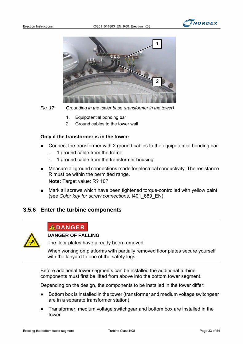
Fig. 17 Grounding in the tower base (transformer in the tower)
1. Equipotential bonding bar2. Ground cables to the tower wall
Only if the transformer is in the tower:
■ Connect the transformer with 2 ground cables to the equipotential bonding bar:- 1 ground cable from the frame- 1 ground cable from the transformer housing
■ Measure all ground connections made for electrical conductivity. The resistance R must be within the permitted range.Note: Target value: R? 10?
■ Mark all screws which have been tightened torque-controlled with yellow paint (see Color key for screw connections, I401_689_EN)
3.5.6 Enter the turbine components
Before additional tower segments can be installed the additional turbine components must first be lifted from above into the bottom tower segment.
Depending on the design, the components to be installed in the tower differ:
● Bottom box is installed in the tower (transformer and medium voltage switchgear are in a separate transformer station)
● Transformer, medium voltage switchgear and bottom box are installed in the tower
DANGER OF FALLINGThe floor plates have already been removed.
When working on platforms with partially removed floor plates secure yourself with the lanyard to one of the safety lugs.
1
2
DANGER
Erecting the bottom tower segment Turbine Class K08 Page 33 of 54
K0801_014863_EN_R00_Erection_K08 Erection Instructions
Transformer and medium voltage switchgear in a separate transformer station
Only the bottom box has to be entered into the tower segment.
■ Attach the bottom box to the large crane (see "Attach the bottom box" page 20)
■ Carefully lift the bottom box into the bottom tower segment
■ Lower the bottom box onto the bottom platform and align
■ Screw the bottom box to the platform
■ Where provided, remove the transport cross bars from the bottom box
■ Arrange for the transport cross bars to be returned to the manufacturer
■ Ground the bottom box over the equipotential bonding bar preassembled
■ Move the removed floor plates by crane into the tower
■ Install the floor plates in the tower
Transformer is in the tower
The bottom box and the medium voltage switchgear must be entered into the tower segment.
DANGER OF FALLINGThe floor plates have already been removed.
When working on platforms with partially removed floor plates secure yourself with the lanyard to one of the safety lugs.
DO NOT REMOVE THE TARPAULINOnly remove the tarpaulin from the switch cabinet when the nacelle has been fitted onto the tower.
DANGER OF FALLINGThe floor plates have already been removed.
When working on platforms with partially removed floor plates secure yourself with the lanyard to one of the safety lugs.
CAUTION
N O T I C E
DANGER
Page 34 of 54 Turbine Class K08 Erecting the bottom tower segment
Erection Instructions K0801_014863_EN_R00_Erection_K08
■ Ensure that the protective cage of the transformer and floor plates from the upper platforms have been removed
■ Attach the medium voltage switchgear to the large crane
■ Lower the medium voltage switchgear onto the bottom platform and align
■ Screw the medium voltage switchgear to the floor plate
■ Refit the protective cage of the transformer
■ Fit the floor plates of the platform above the transformer
■ Move the bottom box by crane into the tower
■ Place the bottom box onto the bottom platform and align
■ Screw the bottom box to the platform
■ Where provided, remove the transport cross bars from the bottom box
■ Arrange for the transport cross bars to be returned to the manufacturer
Completion
■ Move the remaining floor plates by crane into the tower
■ Install the remaining floor plates in the tower
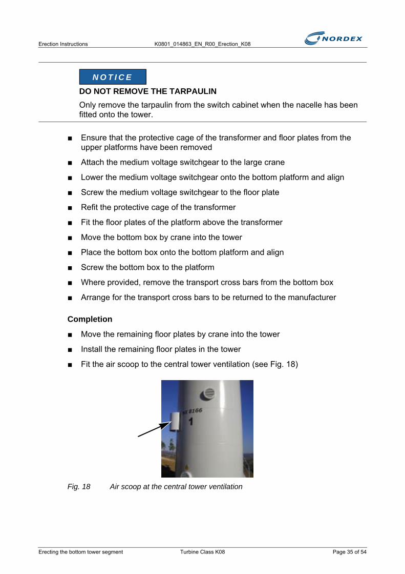
■ Fit the air scoop to the central tower ventilation (see Fig. 18)
Fig. 18 Air scoop at the central tower ventilation
DO NOT REMOVE THE TARPAULINOnly remove the tarpaulin from the switch cabinet when the nacelle has been fitted onto the tower.
N O T I C E
Erecting the bottom tower segment Turbine Class K08 Page 35 of 54

K0801_014863_EN_R00_Erection_K08 Erection Instructions
3.6 Erecting the remaining tower segments
3.6.1 Preparatory work on the erected tower segment■ Fill the toolbox on the ground with all the necessary materials and tools for the
tower flange connection:- Screws- Washers- Nuts- Impact wrench with suitable bit- Wrench for countering- Silicone gun with at least 2 cartridges of sealant- Tower ground cable- Compression sleeves- Shrink hose- Other required material
■ Attach the filled toolbox to the large crane and lift it onto the top platform
■ Ascend the top platform
■ Remove the required tools and materials from the toolbox
■ Lower the toolbox by crane
■ If the tower segment is still attached to the crane remove the lifting tackle from the tower flangeNote: The lifting tackle remains on the crane.
UNSTABLE TOWERDangerous tower oscillations may arise if the top conical tower segment and the nacelle are not fitted on the same day.
Only fit the top tower segment together with the nacelle.
DANGER OF FALLINGOnly enter the access ladder with personal protective equipment (PPE)!
• Always secure yourself to the fall arrest system using the correct fall arrest slider
• If the fall arrest system is not yet operational, use the two lanyards of the PPE alternately for protection
• Only attach to the rungs of the access ladder
WARNING
DANGER
Page 36 of 54 Turbine Class K08 Erecting the remaining tower segments

Erection Instructions K0801_014863_EN_R00_Erection_K08
■ Distribute the tower screws, washers and nuts ready for use on the platform
■ Undo the links of the access ladder
■ Press the links into the ends of the access ladder
■ If a short access ladder link is provided, place this with a 2nd pair of links onto the installed access ladder
Fig. 19 Access ladder links
3.6.2 Prepare the tower segment to be erected■ Check that the tower interiors have been completely and correctly fastened in
the tower (cable brackets, access ladder, platforms, lighting)
■ Carry out a visual inspection of the access ladder
■ Where available, carry out a visual inspection of the fall arrest railNote: Fall arrester must only be inspected by specially trained experts.► At the top end of the fall arrest rail a rail connection must have been fitted as
a stopper (see Fig. 20)Note: The fall arrest rail can now already be released by an expert
Fig. 20 Rail connector at the fall arrest rail
Erecting the remaining tower segments Turbine Class K08 Page 37 of 54
K0801_014863_EN_R00_Erection_K08 Erection Instructions
Only for tower segments with T flanges on both sides
■ Fit the external platform in accordance with Instructions I202_721_EN
■ Fill the toolbox with the necessary materials and tools
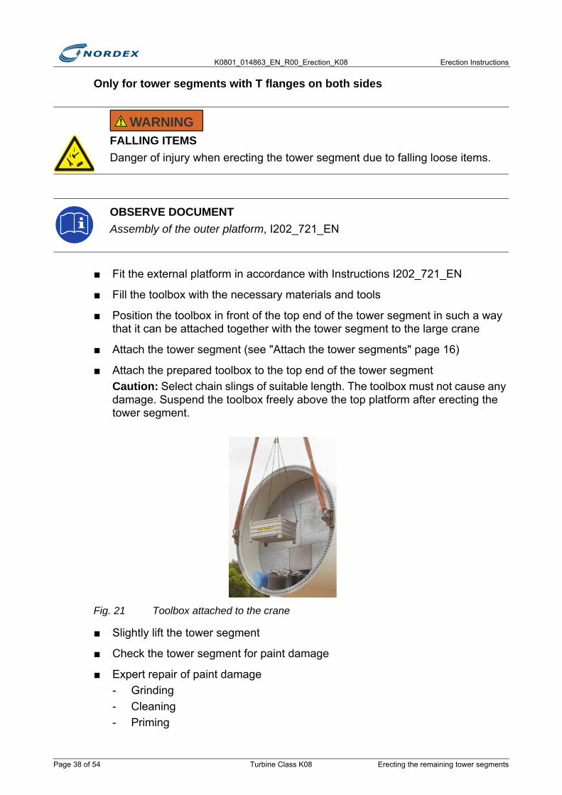
■ Position the toolbox in front of the top end of the tower segment in such a way that it can be attached together with the tower segment to the large crane
■ Attach the tower segment (see "Attach the tower segments" page 16)
■ Attach the prepared toolbox to the top end of the tower segmentCaution: Select chain slings of suitable length. The toolbox must not cause any damage. Suspend the toolbox freely above the top platform after erecting the tower segment.
Fig. 21 Toolbox attached to the crane
■ Slightly lift the tower segment
■ Check the tower segment for paint damage
■ Expert repair of paint damage- Grinding- Cleaning- Priming
FALLING ITEMSDanger of injury when erecting the tower segment due to falling loose items.
OBSERVE DOCUMENTAssembly of the outer platform, I202_721_EN
WARNING
Page 38 of 54 Turbine Class K08 Erecting the remaining tower segments
Erection Instructions K0801_014863_EN_R00_Erection_K08
- Painting
3.6.3 Erect the tower segment
■ Erect the tower segment:- The large crane pulls up- The small crane follows with the tower until the tower is suspended vertically
■ When the tower is suspended vertically, relieve and detach the load on the small crane
■ Enquire the weight of the tower segment from the crane operator
■ Log the weight of the tower segment in the Erection Report (K202_601_IN)
Just before erecting the next tower segment
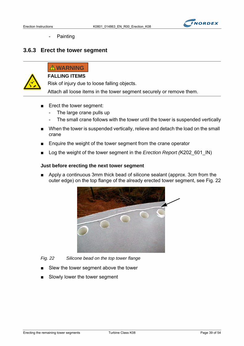
■ Apply a continuous 3mm thick bead of silicone sealant (approx. 3cm from the outer edge) on the top flange of the already erected tower segment, see Fig. 22
Fig. 22 Silicone bead on the top tower flange
■ Slew the tower segment above the tower
■ Slowly lower the tower segment
FALLING ITEMSRisk of injury due to loose falling objects.
Attach all loose items in the tower segment securely or remove them.
WARNING
Erecting the remaining tower segments Turbine Class K08 Page 39 of 54

K0801_014863_EN_R00_Erection_K08 Erection Instructions
■ Rotate the tower segment such that the access ladder can be connected
■ Insert 2 guide pins from above through the flange holes and adjust the tower segment (see Fig. 23)
Fig. 23 Guide pin
3.6.4 Connect the tower segments■ Slowly lower the tower segment. Insert the guide pins into the corresponding
holes of the already erected tower segment.
■ Lower the tower segment further and insert further ladder links
■ Fully relieve the load on the crane
■ Place the toolbox onto the top platform
■ Connect the cables for the power supply of the tower in order to be able to commission the lighting.
SUSPENDED LOADThe freely suspended tower segment can slew to the side!
The following applies to the installers on the top platform of the already erected tower segment:
Remain in a cowered position under the tower flange until the tower segment to be fitted has come to rest just above the flange!
WARNING
Page 40 of 54 Turbine Class K08 Erecting the remaining tower segments
Erection Instructions K0801_014863_EN_R00_Erection_K08
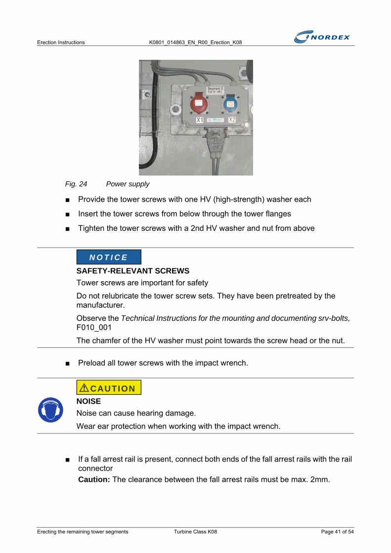
Fig. 24 Power supply
■ Provide the tower screws with one HV (high-strength) washer each
■ Insert the tower screws from below through the tower flanges
■ Tighten the tower screws with a 2nd HV washer and nut from above
■ Preload all tower screws with the impact wrench.
■ If a fall arrest rail is present, connect both ends of the fall arrest rails with the rail connectorCaution: The clearance between the fall arrest rails must be max. 2mm.
SAFETY-RELEVANT SCREWSTower screws are important for safety
Do not relubricate the tower screw sets. They have been pretreated by the manufacturer.
Observe the Technical Instructions for the mounting and documenting srv-bolts, F010_001
The chamfer of the HV washer must point towards the screw head or the nut.
NOISENoise can cause hearing damage.
Wear ear protection when working with the impact wrench.
N O T I C E
CAUTION
Erecting the remaining tower segments Turbine Class K08 Page 41 of 54

K0801_014863_EN_R00_Erection_K08 Erection Instructions
Fig. 25 Rail connector at the fall arrest rail
3.6.5 Ground the tower flanges4 connector bases each with a M12 tap hole have been welded to the tower flanges. These connector bases are intended for grounding the tower flanges.
Caution: Always ground each tower segment immediately after erection and before the next tower segment is installed.
■ Remove paint and contamination from the connector base
■ Coat connector bases with copper grease
Fig. 26 Grounding the tower flanges
■ Screw the preassembled ground cable to the connector bases provided
NOTERework on the ends of the fall arrest rails must only be carried out with a certificate from HACA.
If a fall arrest rope is intended instead of a fall arrest rail, only fit the fall arrest rope after all tower segments have been erected.
Page 42 of 54 Turbine Class K08 Erecting the remaining tower segments

Erection Instructions K0801_014863_EN_R00_Erection_K08
Hexagon screws M12, tightening torque 71Nm
■ Measure the electrical conductivity of the ground connection. The resistance R must be within the permitted range.Note: Target value: R? 10?
■ Mark all screws which have been tightened torque-controlled with yellow paint (see Color key for screw connections, I401_689_EN)
3.6.6 Fit the external screw connections■ Insert and preload the external screw connections to the tower segments with 2
T flanges prior to installing the rotor blades
■ Tighten the external screw connections to the correct tightening torque before completing the erection work
When the next tower segment has been positioned:
■ Ascent the external platform using the outside ladder
■ Strictly observe the safety instructions for the use of access ladders with fall protection system (see Safety Manual, NALL16_010214_EN)
■ After entering the external platform immediately attach the snap hook of the lanyards to the safety rail
FALLING ITEMSWhen working on an external platform no persons may be present within a radius of 15m around the tower.
DANGER OF FALLINGThere is a risk of falling if the snap hook is moved without being secured.
Before moving the snap hook always secure with the 2nd lanyard!
WARNING
DANGER
Erecting the remaining tower segments Turbine Class K08 Page 43 of 54
K0801_014863_EN_R00_Erection_K08 Erection Instructions
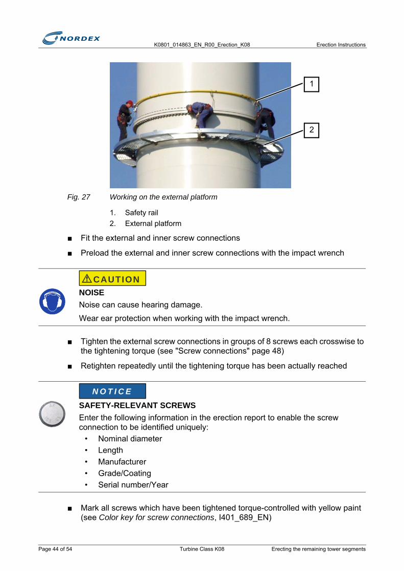
Fig. 27 Working on the external platform
1. Safety rail2. External platform
■ Fit the external and inner screw connections
■ Preload the external and inner screw connections with the impact wrench
■ Tighten the external screw connections in groups of 8 screws each crosswise to the tightening torque (see "Screw connections" page 48)
■ Retighten repeatedly until the tightening torque has been actually reached
■ Mark all screws which have been tightened torque-controlled with yellow paint (see Color key for screw connections, I401_689_EN)
NOISENoise can cause hearing damage.
Wear ear protection when working with the impact wrench.
SAFETY-RELEVANT SCREWSEnter the following information in the erection report to enable the screw connection to be identified uniquely:
• Nominal diameter• Length• Manufacturer• Grade/Coating• Serial number/Year
2
1
CAUTION
N O T I C E
Page 44 of 54 Turbine Class K08 Erecting the remaining tower segments
Erection Instructions K0801_014863_EN_R00_Erection_K08
■ Preserve the screw heads, washers and nuts of the external screw connections with protective wax
■ Fit protective caps to the nuts
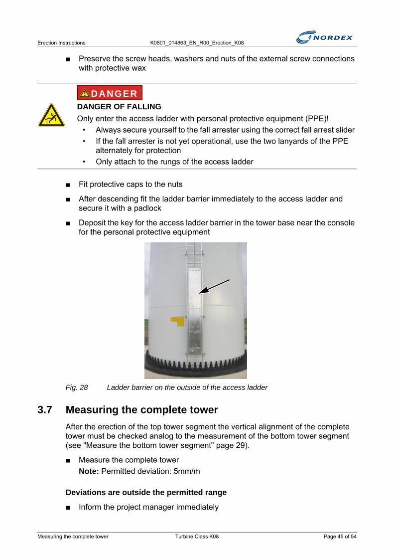
■ After descending fit the ladder barrier immediately to the access ladder and secure it with a padlock
■ Deposit the key for the access ladder barrier in the tower base near the console for the personal protective equipment
Fig. 28 Ladder barrier on the outside of the access ladder
3.7 Measuring the complete towerAfter the erection of the top tower segment the vertical alignment of the complete tower must be checked analog to the measurement of the bottom tower segment (see "Measure the bottom tower segment" page 29).
■ Measure the complete towerNote: Permitted deviation: 5mm/m
Deviations are outside the permitted range
■ Inform the project manager immediately
DANGER OF FALLINGOnly enter the access ladder with personal protective equipment (PPE)!
• Always secure yourself to the fall arrester using the correct fall arrest slider• If the fall arrester is not yet operational, use the two lanyards of the PPE
alternately for protection• Only attach to the rungs of the access ladder
DANGER
Measuring the complete tower Turbine Class K08 Page 45 of 54
K0801_014863_EN_R00_Erection_K08 Erection Instructions
■ Complete the Non-Conformity Report
■ Await further decisions
3.8 Tightening the tower screw connectionsThe tower screw connections which so far have only been preloaded must be tightened to the specified tightening torque after completion of the crane work.
■ Tighten the screw connections in groups of 8 screws each crosswise to the specified tightening torque using a hydraulic wrench (see "Screw connections" page 48
■ Repeat tightening until all screw connections have the specified tightening torque.
DANGER OF FALLINGOnly enter the access ladder with personal protective equipment (PPE)!
• Always secure yourself to the fall arrest system using the correct fall arrest slider
• If the fall arrester is not yet operational, use the two lanyards of the PPE alternately for protection
• Only attach to the rungs of the access ladder
SCREW CONNECTIONS CAN COME LOOSEBecause flange distortions are possible, already tightened screw connections will undo again.
Check and retighten already tightened screw connections until all screw connections have reached the specified tightening torque.
SAFETY-RELEVANT SCREWSEnter the following information in the erection report to enable the screw connection to be identified uniquely:
• Nominal diameter• Length• Manufacturer• Grade/Coating• Serial number/Year
DANGER
N O T I C E
N O T I C E
Page 46 of 54 Turbine Class K08 Tightening the tower screw connections
Erection Instructions K0801_014863_EN_R00_Erection_K08
■ Mark all screws which have been tightened torque-controlled with yellow paint (see Color key for screw connections, I401_689_EN)
3.9 Fitting the fall arrest ropeInstead of a fall arrest rail a fall arrest rope can also be provided as fall protection system.
Rope-guided fall arrester HACA
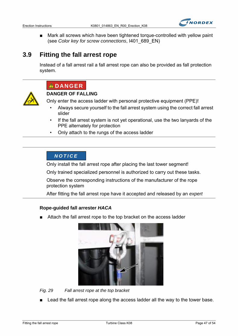
■ Attach the fall arrest rope to the top bracket on the access ladder
Fig. 29 Fall arrest rope at the top bracket
■ Lead the fall arrest rope along the access ladder all the way to the tower base.
DANGER OF FALLINGOnly enter the access ladder with personal protective equipment (PPE)!
• Always secure yourself to the fall arrest system using the correct fall arrest slider
• If the fall arrest system is not yet operational, use the two lanyards of the PPE alternately for protection
• Only attach to the rungs of the access ladder
Only install the fall arrest rope after placing the last tower segment!
Only trained specialized personnel is authorized to carry out these tasks.
Observe the corresponding instructions of the manufacturer of the rope protection system
After fitting the fall arrest rope have it accepted and released by an expert
DANGER
N O T I C E
Fitting the fall arrest rope Turbine Class K08 Page 47 of 54
K0801_014863_EN_R00_Erection_K08 Erection Instructions
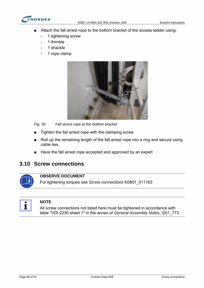
■ Attach the fall arrest rope to the bottom bracket of the access ladder using: - 1 tightening screw- 1 thimble- 1 shackle- 1 rope clamp
Fig. 30 Fall arrest rope at the bottom bracket
■ Tighten the fall arrest rope with the clamping screw
■ Roll up the remaining length of the fall arrest rope into a ring and secure using cable ties.
■ Have the fall arrest rope accepted and approved by an expert
3.10 Screw connections
OBSERVE DOCUMENTFor tightening torques see Screw connections K0801_011163
NOTEAll screw connections not listed here must be tightened in accordance with table "VDI 2230 sheet 1" in the annex of General Assembly Notes, I201_773.
Page 48 of 54 Turbine Class K08 Screw connections
Erection Instructions K0801_014863_EN_R00_Erection_K08
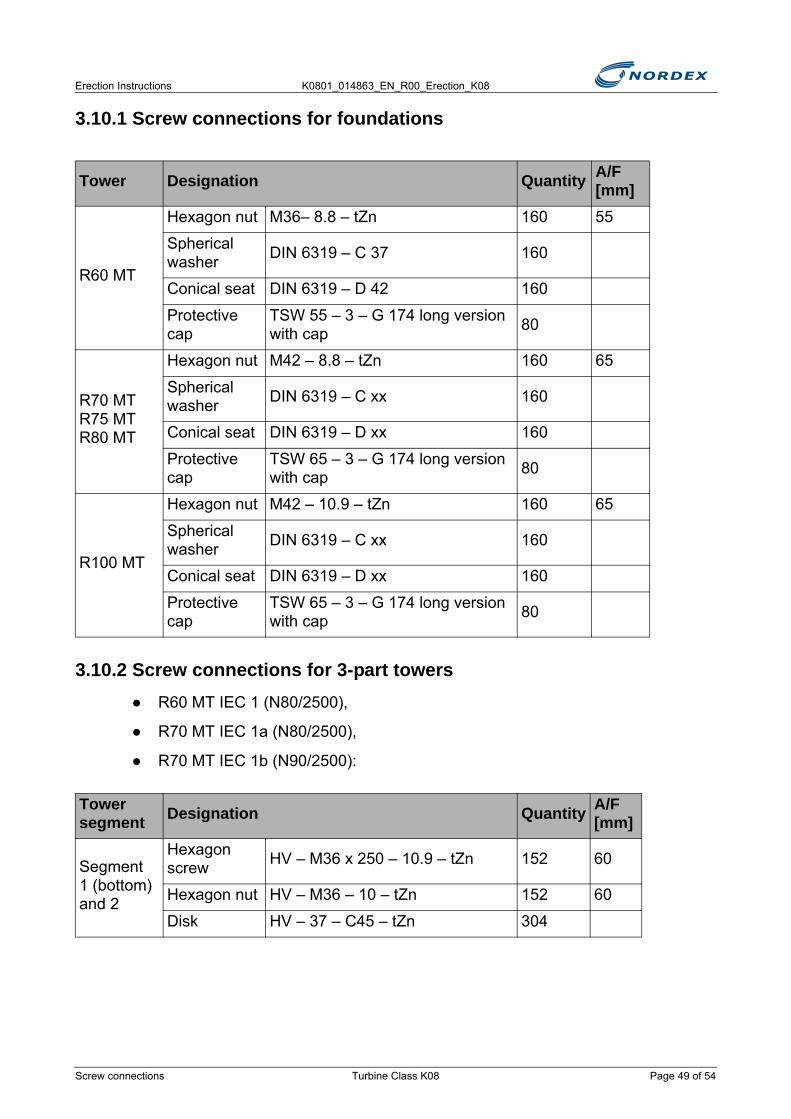
3.10.1 Screw connections for foundations
3.10.2 Screw connections for 3-part towers● R60 MT IEC 1 (N80/2500),
● R70 MT IEC 1a (N80/2500),
● R70 MT IEC 1b (N90/2500):
Tower Designation Quantity A/F [mm]
R60 MT
Hexagon nut M36– 8.8 – tZn 160 55
Spherical washer DIN 6319 – C 37 160
Conical seat DIN 6319 – D 42 160
Protective cap
TSW 55 – 3 – G 174 long version with cap 80
R70 MTR75 MTR80 MT
Hexagon nut M42 – 8.8 – tZn 160 65
Spherical washer DIN 6319 – C xx 160
Conical seat DIN 6319 – D xx 160
Protective cap
TSW 65 – 3 – G 174 long version with cap 80
R100 MT
Hexagon nut M42 – 10.9 – tZn 160 65
Spherical washer DIN 6319 – C xx 160
Conical seat DIN 6319 – D xx 160
Protective cap
TSW 65 – 3 – G 174 long version with cap 80
Tower segment Designation Quantity A/F
[mm]
Segment 1 (bottom) and 2
Hexagon screw HV – M36 x 250 – 10.9 – tZn 152 60
Hexagon nut HV – M36 – 10 – tZn 152 60
Disk HV – 37 – C45 – tZn 304
Screw connections Turbine Class K08 Page 49 of 54
K0801_014863_EN_R00_Erection_K08 Erection Instructions
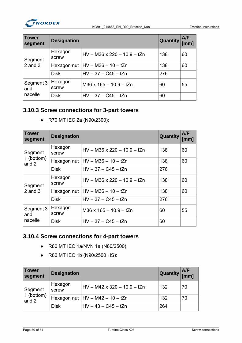
3.10.3 Screw connections for 3-part towers● R70 MT IEC 2a (N90/2300):
3.10.4 Screw connections for 4-part towers● R80 MT IEC 1a/NVN 1a (N80/2500),
● R80 MT IEC 1b (N90/2500 HS):
Segment 2 and 3
Hexagon screw HV – M36 x 220 – 10.9 – tZn 138 60
Hexagon nut HV – M36 – 10 – tZn 138 60
Disk HV – 37 – C45 – tZn 276
Segment 3 and nacelle
Hexagon screw M36 x 165 – 10.9 – tZn 60 55
Disk HV – 37 – C45 – tZn 60
Tower segment Designation Quantity A/F
[mm]
Segment 1 (bottom) and 2
Hexagon screw HV – M36 x 220 – 10.9 – tZn 138 60
Hexagon nut HV – M36 – 10 – tZn 138 60
Disk HV – 37 – C45 – tZn 276
Segment 2 and 3
Hexagon screw HV – M36 x 220 – 10.9 – tZn 138 60
Hexagon nut HV – M36 – 10 – tZn 138 60
Disk HV – 37 – C45 – tZn 276
Segment 3 and nacelle
Hexagon screw M36 x 165 – 10.9 – tZn 60 55
Disk HV – 37 – C45 – tZn 60
Tower segment Designation Quantity A/F
[mm]
Segment 1 (bottom) and 2
Hexagon screw HV – M42 x 320 – 10.9 – tZn 132 70
Hexagon nut HV – M42 – 10 – tZn 132 70
Disk HV – 43 – C45 – tZn 264
Tower segment Designation Quantity A/F
[mm]
Page 50 of 54 Turbine Class K08 Screw connections
Erection Instructions K0801_014863_EN_R00_Erection_K08
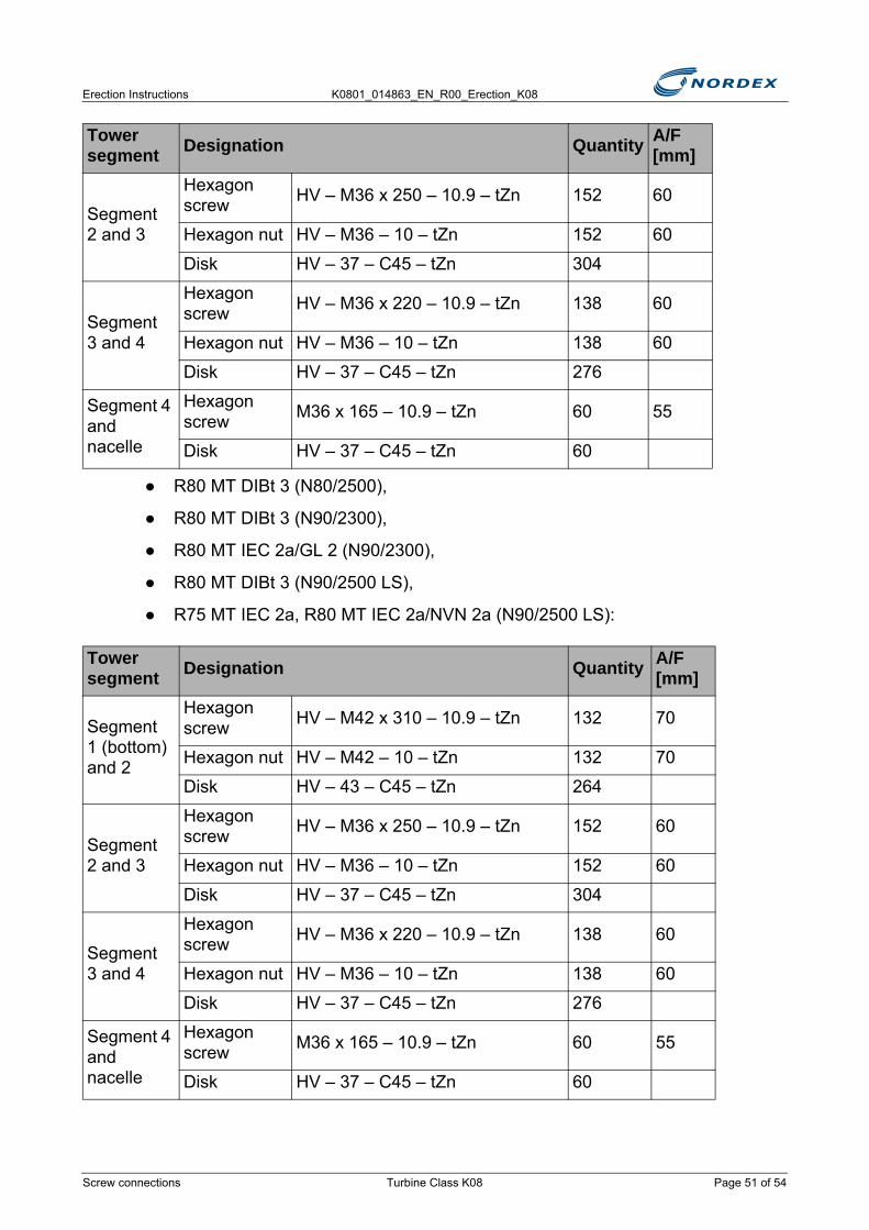
● R80 MT DIBt 3 (N80/2500),
● R80 MT DIBt 3 (N90/2300),
● R80 MT IEC 2a/GL 2 (N90/2300),
● R80 MT DIBt 3 (N90/2500 LS),
● R75 MT IEC 2a, R80 MT IEC 2a/NVN 2a (N90/2500 LS):
Segment 2 and 3
Hexagon screw HV – M36 x 250 – 10.9 – tZn 152 60
Hexagon nut HV – M36 – 10 – tZn 152 60
Disk HV – 37 – C45 – tZn 304
Segment 3 and 4
Hexagon screw HV – M36 x 220 – 10.9 – tZn 138 60
Hexagon nut HV – M36 – 10 – tZn 138 60
Disk HV – 37 – C45 – tZn 276
Segment 4 and nacelle
Hexagon screw M36 x 165 – 10.9 – tZn 60 55
Disk HV – 37 – C45 – tZn 60
Tower segment Designation Quantity A/F
[mm]
Segment 1 (bottom) and 2
Hexagon screw HV – M42 x 310 – 10.9 – tZn 132 70
Hexagon nut HV – M42 – 10 – tZn 132 70
Disk HV – 43 – C45 – tZn 264
Segment 2 and 3
Hexagon screw HV – M36 x 250 – 10.9 – tZn 152 60
Hexagon nut HV – M36 – 10 – tZn 152 60
Disk HV – 37 – C45 – tZn 304
Segment 3 and 4
Hexagon screw HV – M36 x 220 – 10.9 – tZn 138 60
Hexagon nut HV – M36 – 10 – tZn 138 60
Disk HV – 37 – C45 – tZn 276
Segment 4 and nacelle
Hexagon screw M36 x 165 – 10.9 – tZn 60 55
Disk HV – 37 – C45 – tZn 60
Tower segment Designation Quantity A/F
[mm]
Screw connections Turbine Class K08 Page 51 of 54
K0801_014863_EN_R00_Erection_K08 Erection Instructions
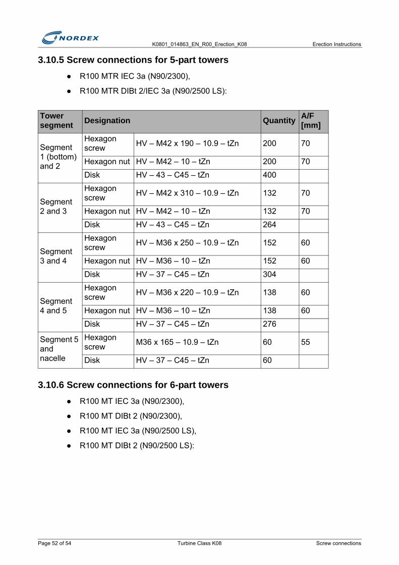
3.10.5 Screw connections for 5-part towers● R100 MTR IEC 3a (N90/2300),
● R100 MTR DIBt 2/IEC 3a (N90/2500 LS):
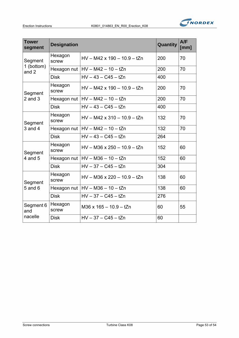
3.10.6 Screw connections for 6-part towers● R100 MT IEC 3a (N90/2300),
● R100 MT DIBt 2 (N90/2300),
● R100 MT IEC 3a (N90/2500 LS),
● R100 MT DIBt 2 (N90/2500 LS):
Tower segment Designation Quantity A/F
[mm]
Segment 1 (bottom) and 2
Hexagon screw HV – M42 x 190 – 10.9 – tZn 200 70
Hexagon nut HV – M42 – 10 – tZn 200 70
Disk HV – 43 – C45 – tZn 400
Segment 2 and 3
Hexagon screw HV – M42 x 310 – 10.9 – tZn 132 70
Hexagon nut HV – M42 – 10 – tZn 132 70
Disk HV – 43 – C45 – tZn 264
Segment 3 and 4
Hexagon screw HV – M36 x 250 – 10.9 – tZn 152 60
Hexagon nut HV – M36 – 10 – tZn 152 60
Disk HV – 37 – C45 – tZn 304
Segment 4 and 5
Hexagon screw HV – M36 x 220 – 10.9 – tZn 138 60
Hexagon nut HV – M36 – 10 – tZn 138 60
Disk HV – 37 – C45 – tZn 276
Segment 5 and nacelle
Hexagon screw M36 x 165 – 10.9 – tZn 60 55
Disk HV – 37 – C45 – tZn 60
Page 52 of 54 Turbine Class K08 Screw connections
Erection Instructions K0801_014863_EN_R00_Erection_K08
Tower segment Designation Quantity A/F
[mm]
Segment 1 (bottom) and 2
Hexagon screw HV – M42 x 190 – 10.9 – tZn 200 70
Hexagon nut HV – M42 – 10 – tZn 200 70
Disk HV – 43 – C45 – tZn 400
Segment 2 and 3
Hexagon screw HV – M42 x 190 – 10.9 – tZn 200 70
Hexagon nut HV – M42 – 10 – tZn 200 70
Disk HV – 43 – C45 – tZn 400
Segment 3 and 4
Hexagon screw HV – M42 x 310 – 10.9 – tZn 132 70
Hexagon nut HV – M42 – 10 – tZn 132 70
Disk HV – 43 – C45 – tZn 264
Segment 4 and 5
Hexagon screw HV – M36 x 250 – 10.9 – tZn 152 60
Hexagon nut HV – M36 – 10 – tZn 152 60
Disk HV – 37 – C45 – tZn 304
Segment 5 and 6
Hexagon screw HV – M36 x 220 – 10.9 – tZn 138 60
Hexagon nut HV – M36 – 10 – tZn 138 60
Disk HV – 37 – C45 – tZn 276
Segment 6 and nacelle
Hexagon screw M36 x 165 – 10.9 – tZn 60 55
Disk HV – 37 – C45 – tZn 60
Screw connections Turbine Class K08 Page 53 of 54

K0801_014863_EN_R00_Erection_K08 Erection Instructions
Page 54 of 54 Turbine Class K08 Screw connections
Erection Instructions K0801_014863_EN_R00_Erection_K08
4. Tower completionTo complete the tower the following tasks need to be carried out:
● Preserving the foundation screw connection
● Assembling the service lift
● Fitting the insulation for the bottom box
● Fitting the cooling systems of the bottom box
● Sealing the tower
● Fitting the fire extinguishers
● Attaching the warning signs
● Storing the rescue and abseiling equipment
4.1 Preserving the foundation screw connection
■ Spray the anchor bolts, washers and nuts with a protective wax against corrosion.
■ Tighten the foundation screw connection to the tightening torque (see K0801_011163_EN)
■ Press 1 black protective cap onto each external screw connection (see fig. 31, item 1)
TIGHTEN THE ANCHOR BOLTSTighten all anchor bolts before preservation
OBSERVE DOCUMENTFor tightening torques for the foundation screw connections see Screw connections for erection (K0801_011163_EN)
Do not apply a bitumen insulating coat to the tower, screw connections and load-spreading plate
N O T I C E
N O T I C E
Preserving the foundation screw connection Turbine Class K08 Page 55 of 64
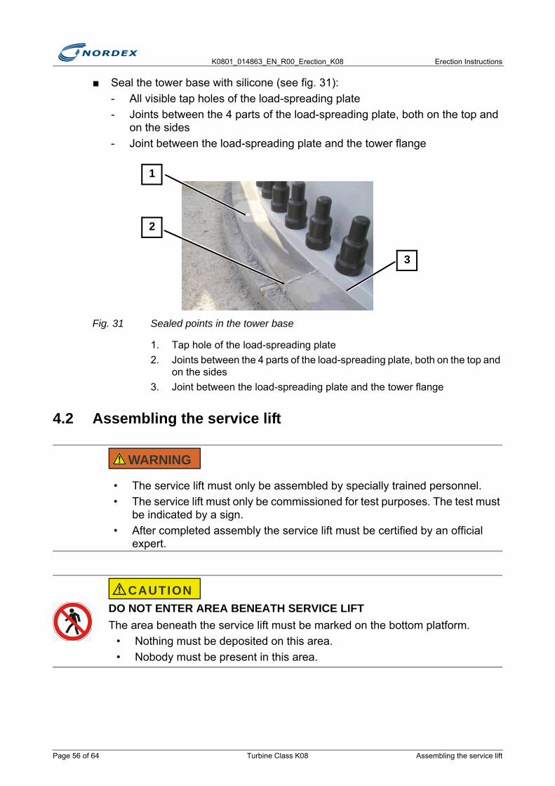
K0801_014863_EN_R00_Erection_K08 Erection Instructions
■ Seal the tower base with silicone (see fig. 31):- All visible tap holes of the load-spreading plate- Joints between the 4 parts of the load-spreading plate, both on the top and
on the sides- Joint between the load-spreading plate and the tower flange
Fig. 31 Sealed points in the tower base
1. Tap hole of the load-spreading plate2. Joints between the 4 parts of the load-spreading plate, both on the top and
on the sides3. Joint between the load-spreading plate and the tower flange
4.2 Assembling the service lift
• The service lift must only be assembled by specially trained personnel.• The service lift must only be commissioned for test purposes. The test must
be indicated by a sign.• After completed assembly the service lift must be certified by an official
expert.
DO NOT ENTER AREA BENEATH SERVICE LIFTThe area beneath the service lift must be marked on the bottom platform.
• Nothing must be deposited on this area.• Nobody must be present in this area.
3
2
1
WARNING
CAUTION
Page 56 of 64 Turbine Class K08 Assembling the service lift

Erection Instructions K0801_014863_EN_R00_Erection_K08
Work steps to be performed
■ Assemble the service lift in accordance with the Assembly Instructions
■ Complete the Commissioning Report for the service lift
■ Store the Commissioning Report in the space provided in the service lift
4.3 Fitting the insulation for the bottom boxThe insulation for the IDS converter is delivered to the site together with the converter.
Delivery condition
The insulation consists of approx. 4cm thick stable foam sheets.
The foam sheets are numbered and already have the holes for the coolant hoses and control cables.
Work steps to be performed
■ Remove the sheet panels from the long sides of the frame
■ Slide the foam sheets in the sequence IV, III, II, I under the switch cabinet in accordance with the arrows (see fig. 32)
OBSERVE DOCUMENTService lift Assembly Instructions
It is found in a compartment in the wall of the service lift.
NOTEThis chapter is only relevant when:
• An IDS converter is being used.• The transformer is erected inside the tower.
No plastic components may fall onto the transformer.
N O T I C E
Fitting the insulation for the bottom box Turbine Class K08 Page 57 of 64
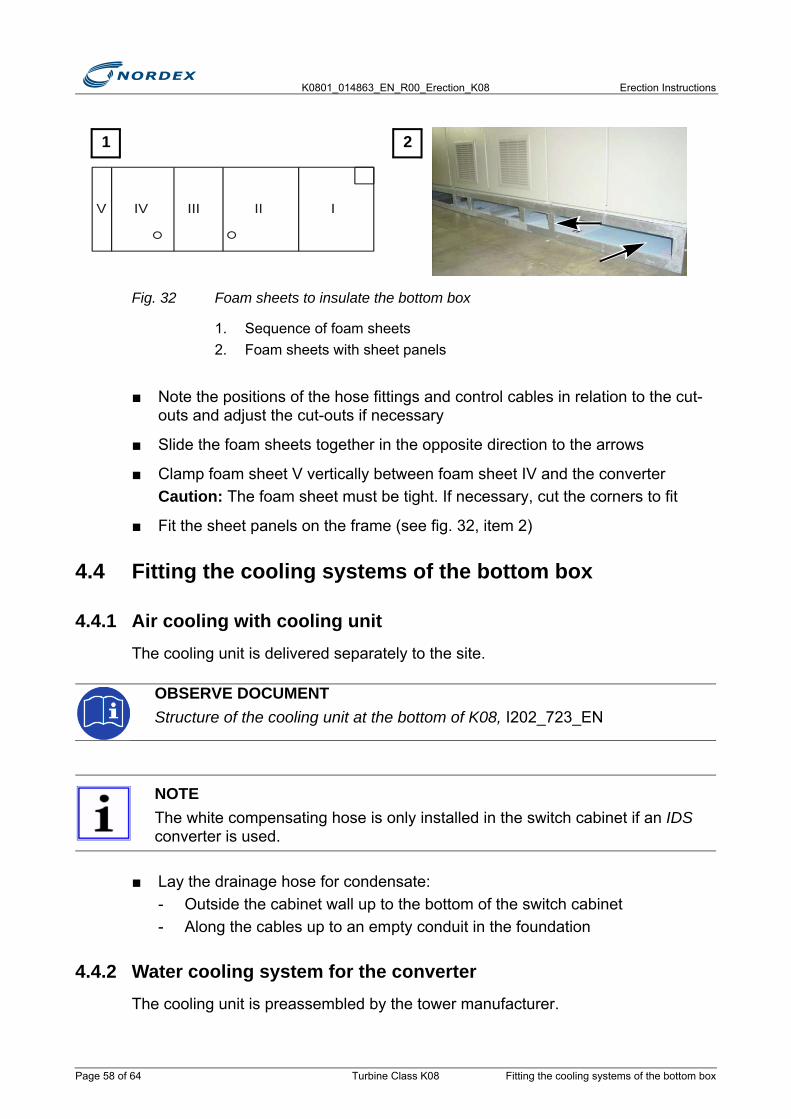
K0801_014863_EN_R00_Erection_K08 Erection Instructions
Fig. 32 Foam sheets to insulate the bottom box
1. Sequence of foam sheets2. Foam sheets with sheet panels
■ Note the positions of the hose fittings and control cables in relation to the cut-outs and adjust the cut-outs if necessary
■ Slide the foam sheets together in the opposite direction to the arrows
■ Clamp foam sheet V vertically between foam sheet IV and the converterCaution: The foam sheet must be tight. If necessary, cut the corners to fit
■ Fit the sheet panels on the frame (see fig. 32, item 2)
4.4 Fitting the cooling systems of the bottom box
4.4.1 Air cooling with cooling unitThe cooling unit is delivered separately to the site.
■ Lay the drainage hose for condensate:- Outside the cabinet wall up to the bottom of the switch cabinet- Along the cables up to an empty conduit in the foundation
4.4.2 Water cooling system for the converterThe cooling unit is preassembled by the tower manufacturer.
OBSERVE DOCUMENTStructure of the cooling unit at the bottom of K08, I202_723_EN
NOTEThe white compensating hose is only installed in the switch cabinet if an IDS converter is used.
1 2
Page 58 of 64 Turbine Class K08 Fitting the cooling systems of the bottom box
Erection Instructions K0801_014863_EN_R00_Erection_K08
All required pipes are already laid.
Location of the water pump unit
The location of the water pump unit depends on the tower design (see table):
Work steps to be performed
■ Connect the cooling circuit to the bottom box/converter
■ Fill the cooling circuit completely with Varidos FSK 45Note: Varidos FSK 45: water/antifreeze mix premixed by the manufacturer (45% antifreeze Varidos FSK; 55% water)
■ Fit the air vent to the heat exchanger above the tower doorCaution: Fit the air vent as high as possible and as vertical as possible. Maximum deviation from the vertical: 10°.
■ After assembly is complete, check the cooling system for leaks
■ Connect the following to field 2 (converter) in the switch cabinet:► Connect the fan of the heat exchanger in accordance with the circuit diagram
page -YS36A at stage L = Low speed► Fit terminal box 1 to the inside of the cooler recess above the doorNote: Terminal box 1 is in the switch cabinet.
Design Location of the water stationStandardThe transformer is outside the tower
Underneath the bottom box platform, next to the tower door
The transformer is in the towerUnderneath the bottom box platform, next to the tower door. The bottom box platform is above the tower door.
Lattice tower In the transformer station
At locations with high outside temperatures, it may also be necessary to connect the High speed stage. In this case, install a jumper in terminal box 1
N O T I C E
Fitting the cooling systems of the bottom box Turbine Class K08 Page 59 of 64
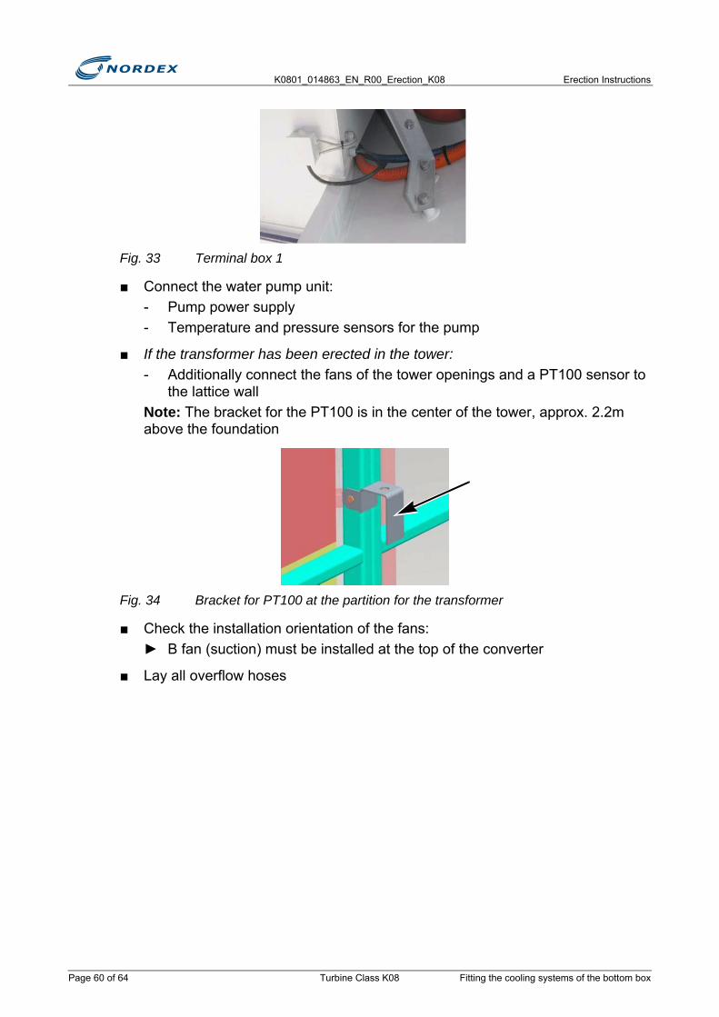
K0801_014863_EN_R00_Erection_K08 Erection Instructions
Fig. 33 Terminal box 1
■ Connect the water pump unit:- Pump power supply- Temperature and pressure sensors for the pump
■ If the transformer has been erected in the tower:- Additionally connect the fans of the tower openings and a PT100 sensor to
the lattice wallNote: The bracket for the PT100 is in the center of the tower, approx. 2.2m above the foundation
Fig. 34 Bracket for PT100 at the partition for the transformer
■ Check the installation orientation of the fans:► B fan (suction) must be installed at the top of the converter
■ Lay all overflow hoses
Page 60 of 64 Turbine Class K08 Fitting the cooling systems of the bottom box

Erection Instructions K0801_014863_EN_R00_Erection_K08
Fig. 35 Overview of the cooling system for the converter
Coolant drainage
There is a drainage hose for coolant at the bottom of the converter
■ Lay the drainage hose along the cables up to a free conduit in the foundationCaution: Observe the Assembly Instructions Converter drainage hose, I403_077_EN
■ If the transformer has been erected in the tower:- Extend the drainage hose- Lay the drainage hose along the lattice
4.5 Sealing the tower■ Replace the provisional locks with panic locks:
- Use the corresponding covers- Seal uncovered holes neatly with silicone
Fig. 36 Door lock
■ Seal the existing gaps and holes between the fan air scoop and the tower entrance- Adjust the material provided to fit- Seal the existing gaps and holes with silicone
Sealing the tower Turbine Class K08 Page 61 of 64

K0801_014863_EN_R00_Erection_K08 Erection Instructions
Fig. 37 Gap above the tower door
4.6 Fitting the fire extinguishersThe number of fire extinguishers required depends on the country and is specified in the contract.
■ Observe the country-specific and contractual specifications
■ Always fit 1 fire extinguisher to the tower wall at the base of the tower next to the door
Fig. 38 Fire extinguisher at the base of the tower
4.7 Attaching the warning signs
NOTEA special bracket is provided for every fire extinguisher
In lattice towers there is one fire extinguisher in the transformer station
OBSERVE DOCUMENTWT signs, I501_050_A01
Page 62 of 64 Turbine Class K08 Fitting the fire extinguishers

Erection Instructions K0801_014863_EN_R00_Erection_K08
■ Attach all signs in the nacelle and the tower
Fig. 39 Warning sign on the tower door
■ Mark protruding threaded rods of the cable brackets with signal paint
■ Position the cable clamps in such a way that the cables go through the center of the hole in the platform
Fig. 40 Protruding threaded rods
4.8 Storing the rescue and abseiling equipment■ Take the rescue and abseiling equipment to the top tower platform
■ Position the box with the rescue and abseiling equipment on the top tower platform, see fig. 41
Storing the rescue and abseiling equipment Turbine Class K08 Page 63 of 64
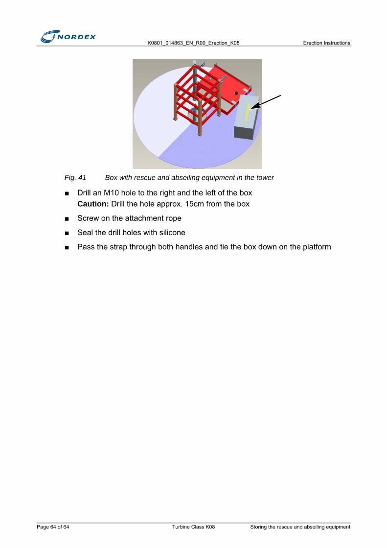
K0801_014863_EN_R00_Erection_K08 Erection Instructions
Fig. 41 Box with rescue and abseiling equipment in the tower
■ Drill an M10 hole to the right and the left of the boxCaution: Drill the hole approx. 15cm from the box
■ Screw on the attachment rope
■ Seal the drill holes with silicone
■ Pass the strap through both handles and tie the box down on the platform
Page 64 of 64 Turbine Class K08 Storing the rescue and abseiling equipment

Erection Instructions K0801_014863_EN_R00_Erection_K08
5. Drive train assemblyThe nacelle and the drive train are delivered separately.
The drive train is installed in the nacelle on the construction site.
5.1 Preparing the machine frameThe drive train is delivered on a transport frame. The transport frame must be aligned horizontally for the drive train to be lifted into the nacelle with the correct installation angle.
■ Align the transport frame horizontally with squared timbers
■ Remove packaging and transport protection from the drive train and the gearbox clampsNote: The transport frame, packaging and transport protection must be returned to Nordex.
■ Remove the adhesive tape between the gearbox clamp halves
■ Clean the gap between the gearbox clamp halves
■ Clean all bearing surfaces on the machine frame► The bearing surfaces must be clean, free from grease, and either bare metal or
coated with zincdust paint
5.2 Attaching and lifting the drive train■ Screw the lifting tackle rotor shaft N80 to the flange of the rotor shaft (see fig. 43)
from behind
■ Attach the drive train at 3 points
Note: The attachment points are the two lifting lugs on the gearbox and on the rotor shaft that are marked in yellow.
OBSERVE DOCUMENTRecord all executed work in the Erection Report I_K202_601.
OBSERVE DOCUMENTTightening torque and reference dimension of the srv studs Assembly Drawing 801 _06_00005.
Preparing the machine frame Turbine Class K08 Page 65 of 78

K0801_014863_EN_R00_Erection_K08 Erection Instructions
Attach drive chain
■ Attach 2 lifting lugs on the gearbox- 2 shackles 55 t capacity each- 2 round slings, 4 m (6 m) effective working length, 40 t capacity
■ Attach lifting tackle Rotor shaft N80- 1 shackle 35 t capacity- 1 round sling 4 m (6 m) m effective working length- 1 adjustable chain
Fig. 42 Adjustable chain
■ Detach the drive train from the transport frame► Remove the screws and tensioning straps from the rotor bearing housing
■ Attach 2 guide ropes to the front and the back of the drive trainNote: The guide ropes must be easy to remove again later.
COMPONENT FRACTURELifting the drive train at an angle or allowing the rotor bearing to slew during assembly when installing the drive train can result in a fracture of the labyrinth in the bearing cover and sealing ring.
Only attach the drive train to the lifting lug on the rotor bearing when the drive train is secured to the transport frame.LEAKING GEARBOX OILTo ensure that no gearbox oil can leak out of the seals, the gearbox must be level during transport and storage.
N O T I C E
Page 66 of 78 Turbine Class K08 Attaching and lifting the drive train
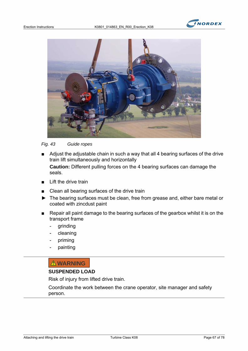
Erection Instructions K0801_014863_EN_R00_Erection_K08
Fig. 43 Guide ropes
■ Adjust the adjustable chain in such a way that all 4 bearing surfaces of the drive train lift simultaneously and horizontallyCaution: Different pulling forces on the 4 bearing surfaces can damage the seals.
■ Lift the drive train
■ Clean all bearing surfaces of the drive train► The bearing surfaces must be clean, free from grease and, either bare metal or
coated with zincdust paint
■ Repair all paint damage to the bearing surfaces of the gearbox whilst it is on the transport frame- grinding- cleaning- priming - painting
SUSPENDED LOADRisk of injury from lifted drive train.
Coordinate the work between the crane operator, site manager and safety person.
WARNING
Attaching and lifting the drive train Turbine Class K08 Page 67 of 78
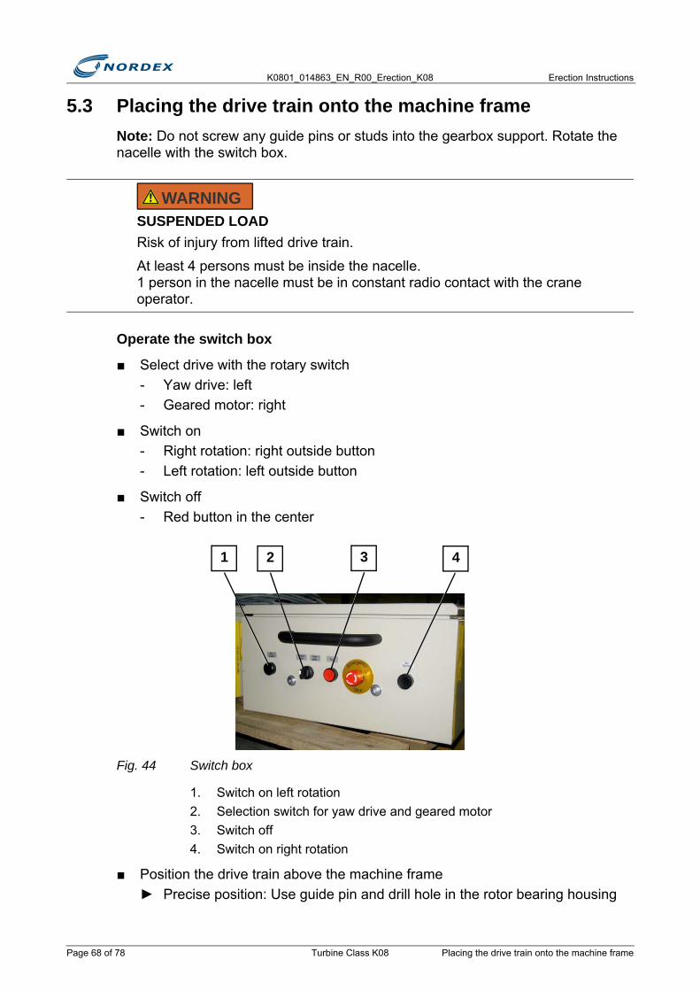
K0801_014863_EN_R00_Erection_K08 Erection Instructions
5.3 Placing the drive train onto the machine frameNote: Do not screw any guide pins or studs into the gearbox support. Rotate the nacelle with the switch box.
Operate the switch box
■ Select drive with the rotary switch - Yaw drive: left - Geared motor: right
■ Switch on- Right rotation: right outside button- Left rotation: left outside button
■ Switch off- Red button in the center
Fig. 44 Switch box
1. Switch on left rotation2. Selection switch for yaw drive and geared motor3. Switch off4. Switch on right rotation
■ Position the drive train above the machine frame► Precise position: Use guide pin and drill hole in the rotor bearing housing
SUSPENDED LOADRisk of injury from lifted drive train.
At least 4 persons must be inside the nacelle. 1 person in the nacelle must be in constant radio contact with the crane operator.
WARNING
41 2 3
Page 68 of 78 Turbine Class K08 Placing the drive train onto the machine frame

Erection Instructions K0801_014863_EN_R00_Erection_K08
■ Lower the drive train to just above the machine frame
■ Check the distance between the drive train and the machine frame► The distance must be the same for all 4 bearing surfaces
■ Rotate the rotor bearing around the rotor shaft to adjust the distance on the right and left sides
■ Lower the drive train until it just touches the machine frame► All 4 bearing surfaces must make contact simultaneously. The gearbox may
touch down a maximum of 10mm earlier.
■ Test the rotor lock bolt once the drive train is in place
■ Remove the guide pin and move the rotor bearing housing laterally if the rotor lock bolt does not fit into the rotor lock disc
■ Secure the rotor bearing housing on the front gearbox supports of the machine frame
■ Lubricate 24 srv studs M36 on both sides
■ Screw in 24 srv studs M36► The identifying mark of the screws must be visible.► The screws must protrude over the bottom gearbox clamp half by 77 +2mm.
COMPONENT FRACTUREThe labyrinth in the bearing cover and sealing ring can fracture if lifted at an angle.
The drive train must touch down simultaneously at the front and the back.
OBSERVE DOCUMENTAssembly drawing 801_06_00003
N O T I C E
Placing the drive train onto the machine frame Turbine Class K08 Page 69 of 78
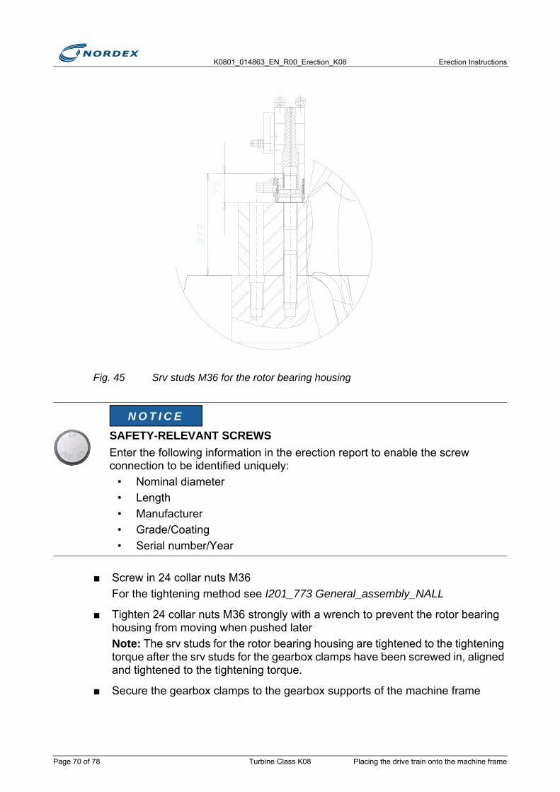
K0801_014863_EN_R00_Erection_K08 Erection Instructions
Fig. 45 Srv studs M36 for the rotor bearing housing
■ Screw in 24 collar nuts M36For the tightening method see I201_773 General_assembly_NALL
■ Tighten 24 collar nuts M36 strongly with a wrench to prevent the rotor bearing housing from moving when pushed laterNote: The srv studs for the rotor bearing housing are tightened to the tightening torque after the srv studs for the gearbox clamps have been screwed in, aligned and tightened to the tightening torque.
■ Secure the gearbox clamps to the gearbox supports of the machine frame
SAFETY-RELEVANT SCREWSEnter the following information in the erection report to enable the screw connection to be identified uniquely:
• Nominal diameter• Length• Manufacturer• Grade/Coating• Serial number/Year
N O T I C E
Page 70 of 78 Turbine Class K08 Placing the drive train onto the machine frame
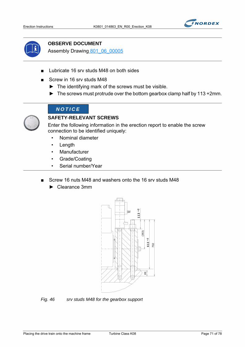
Erection Instructions K0801_014863_EN_R00_Erection_K08
■ Lubricate 16 srv studs M48 on both sides
■ Screw in 16 srv studs M48► The identifying mark of the screws must be visible.► The screws must protrude over the bottom gearbox clamp half by 113 +2mm.
■ Screw 16 nuts M48 and washers onto the 16 srv studs M48► Clearance 3mm
Fig. 46 srv studs M48 for the gearbox support
OBSERVE DOCUMENTAssembly Drawing 801_06_00005
SAFETY-RELEVANT SCREWSEnter the following information in the erection report to enable the screw connection to be identified uniquely:
• Nominal diameter• Length• Manufacturer• Grade/Coating• Serial number/Year
N O T I C E
613
+2
113
+2
69(3
63)
702
Placing the drive train onto the machine frame Turbine Class K08 Page 71 of 78

K0801_014863_EN_R00_Erection_K08 Erection Instructions
5.4 Jacking the drive train apartThe rotor bearing and gearbox are jacked apart to compensate for the total backlash of the bearings.
■ Remove both locking plates from the journals
■ Fit the hydraulic plunger rod on each side between the rotor bearing housing and the gearbox
■ Attach the hydraulic plunger rod to the journal
■ Use the adjustment screw to position the hydraulic plunger rod on the gearbox housing so it is parallel
■ Position the hydraulic plunger rod between the fastening screws for the sets of steps over the shaft
Note: If a set of steps is not installed, use a longer hydraulic plunger rod
Fig. 47 Plunger rods in position
1. Shorter hydraulic plunger rod if there is a set of steps over the shaft2. Longer hydraulic plunger rod positioned directly against the rotor bearing3. Adjustment screw
■ Push both bearings apart with an oil pressure of 450barNote: The oil pressure is generated by a pump in both cylinders.Caution: The rotor brake must be released.
■ Using the rotor brake disc, rotate the rotor shaft at least one full turn
■ Measure the distance traveled with 1 gage on each side of the gearbox
■ Record both readings in the Erection Report
■ Maintain a pressure of 450bar on the hydraulic cylinders of the hydraulic plunger rods
■ Lower the crane until the drive train is resting fully on the machine frame
■ Detach the shackles from the rotor shaft
Page 72 of 78 Turbine Class K08 Jacking the drive train apart

Erection Instructions K0801_014863_EN_R00_Erection_K08
■ Slew with the crane vertically across to the lifting lugs on the gearbox
■ Attach the shackles to the lifting lugs on the gearbox
■ Lift the gearbox with the crane with a load capacity of 18t to relieve the shearing strain on the elastomer bearing bushes of the gearbox supports
■ Lower the crane until the gearbox is resting fully on the machine frame
■ Fully detach the crane► The hydraulic plunger rods remain fitted
■ Attach the guide ropes of the drive train to the shackles Danger: Attach the guide ropes; do not let them fall.
5.5 Screwing the drive train to the machine frameTighten the srv studs for the rotor bearing housing and gearbox support with the hydraulic tightening method.
Tighten the gearbox clamps
■ Lightly tighten the nuts M48 and washers on the gearbox clamps with a wrench
■ Arrange 2 x 2 tightening cylinders M48 crosswise on the nuts in accordance with the tightening plan for gearbox clamps
■ Tighten the srv studs to 1250kN (1300bar)
■ Tighten all nuts M48 in accordance with the Tightening plan for gearbox clamps
Fig. 48 Tightening plan for gearbox clamps
RISK OF INJURYFlying objects following thread fracture.
During the tightening method nobody must be present in front of the tightening cylinders in the direction of the tensile force.
WARNING
1
2
2
1
3
4
4
3
5
6
6
5
7
8
8
7
Screwing the drive train to the machine frame Turbine Class K08 Page 73 of 78
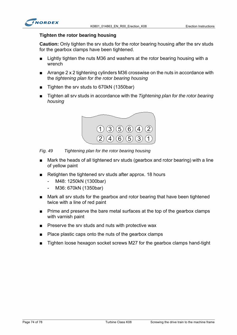
K0801_014863_EN_R00_Erection_K08 Erection Instructions
Tighten the rotor bearing housing
Caution: Only tighten the srv studs for the rotor bearing housing after the srv studs for the gearbox clamps have been tightened.
■ Lightly tighten the nuts M36 and washers at the rotor bearing housing with a wrench
■ Arrange 2 x 2 tightening cylinders M36 crosswise on the nuts in accordance with the tightening plan for the rotor bearing housing
■ Tighten the srv studs to 670kN (1350bar)
■ Tighten all srv studs in accordance with the Tightening plan for the rotor bearing housing
Fig. 49 Tightening plan for the rotor bearing housing
■ Mark the heads of all tightened srv studs (gearbox and rotor bearing) with a line of yellow paint
■ Retighten the tightened srv studs after approx. 18 hours- M48: 1250kN (1300bar)- M36: 670kN (1350bar)
■ Mark all srv studs for the gearbox and rotor bearing that have been tightened twice with a line of red paint
■ Prime and preserve the bare metal surfaces at the top of the gearbox clamps with varnish paint
■ Preserve the srv studs and nuts with protective wax
■ Place plastic caps onto the nuts of the gearbox clamps
■ Tighten loose hexagon socket screws M27 for the gearbox clamps hand-tight
1 3 5 6 42 4 6 5 3
21
Page 74 of 78 Turbine Class K08 Screwing the drive train to the machine frame
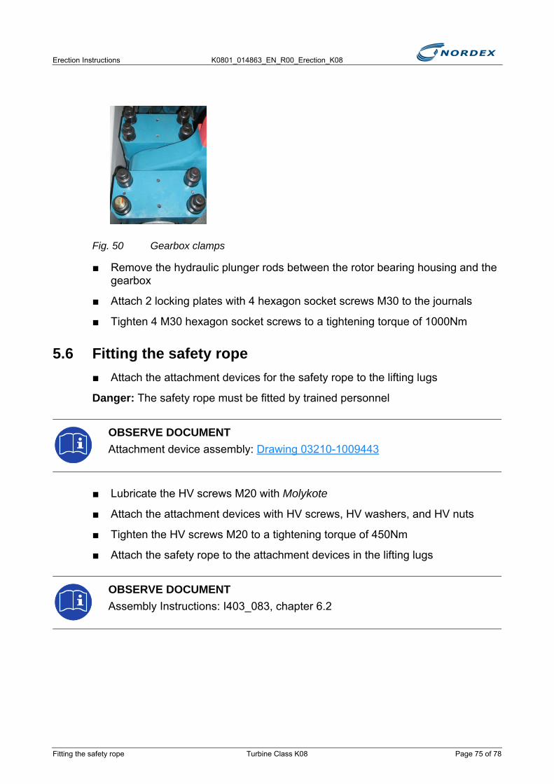
Erection Instructions K0801_014863_EN_R00_Erection_K08
Fig. 50 Gearbox clamps
■ Remove the hydraulic plunger rods between the rotor bearing housing and the gearbox
■ Attach 2 locking plates with 4 hexagon socket screws M30 to the journals
■ Tighten 4 M30 hexagon socket screws to a tightening torque of 1000Nm
5.6 Fitting the safety rope■ Attach the attachment devices for the safety rope to the lifting lugs
Danger: The safety rope must be fitted by trained personnel
■ Lubricate the HV screws M20 with Molykote
■ Attach the attachment devices with HV screws, HV washers, and HV nuts
■ Tighten the HV screws M20 to a tightening torque of 450Nm
■ Attach the safety rope to the attachment devices in the lifting lugs
OBSERVE DOCUMENTAttachment device assembly: Drawing 03210-1009443
OBSERVE DOCUMENTAssembly Instructions: I403_083, chapter 6.2
Fitting the safety rope Turbine Class K08 Page 75 of 78

K0801_014863_EN_R00_Erection_K08 Erection Instructions
Fig. 51 Safety rope installation
1. Rotor bearing housing attachment device2. Generator attachment device
■ Shorten the safety rope with a wire cutter to the final rope length
■ Adjust the spring preload of the energy absorber in accordance with the manufacturer’s instructions
■ Check all executed tasks and record them in the Assembly Report
5.7 Completing the drive train assembly
OBSERVE DOCUMENTEnergy absorber:
OBSERVE DOCUMENTAssembly Report: K403_083
DANGER OF FALLINGPersons are unprotected at the open side of the nacelle.
Only remove the safety rail once the safety rope has been installed. The safety rope is certified for a maximum of 4 persons. All persons must secure themselves to the safety rope by using the PPE.
1
2
DANGER
Page 76 of 78 Turbine Class K08 Completing the drive train assembly
Erection Instructions K0801_014863_EN_R00_Erection_K08
■ Remove the safety rail and the attachment device from the open side of the nacelle
■ Lower the safety rail to the ground with the on-board craneNote: Safety rails are stored in the container.
■ Fit the roof attachment with the bottom screw of the quick-release fasteners
■ Attach the roof pole
■ Remove the webbing slings on the right and left of the machine frameNote: Webbing slings must be returned to Nordex.
Completing the drive train assembly Turbine Class K08 Page 77 of 78

K0801_014863_EN_R00_Erection_K08 Erection Instructions
Page 78 of 78 Turbine Class K08 Completing the drive train assembly
Erection Instructions K0801_014863_EN_R00_Erection_K08
6. Nacelle erectionTo erect the nacelle the following tasks need to be carried out:
● Preparing the nacelle- Opening the nacelle roof- Fitting the lightning arrester- Fitting the air scoop- Fitting and connecting the obstacle lights (optional)- Fitting and connecting the wind sensors- Fitting the safety rail- Connecting the brake motor control box
● Installing the nacelle on the tower- Installing the nacelle- Preparing the nacelle with the drive train
6.1 Preparing the nacelleNote: Where possible carry out the tasks described here on the ground.
6.1.1 Opening the nacelle roofOpen the nacelle roof with the hydraulic unit.
Note: The hydraulic unit is on the machine frame directly behind the access hatch.
■ Move valve 610 to the neutral position
■ Move and keep valve 640 in the Open roof position
■ Operate the hand pump until the nacelle roof is open
Preparing the nacelle Turbine Class K08 Page 79 of 98
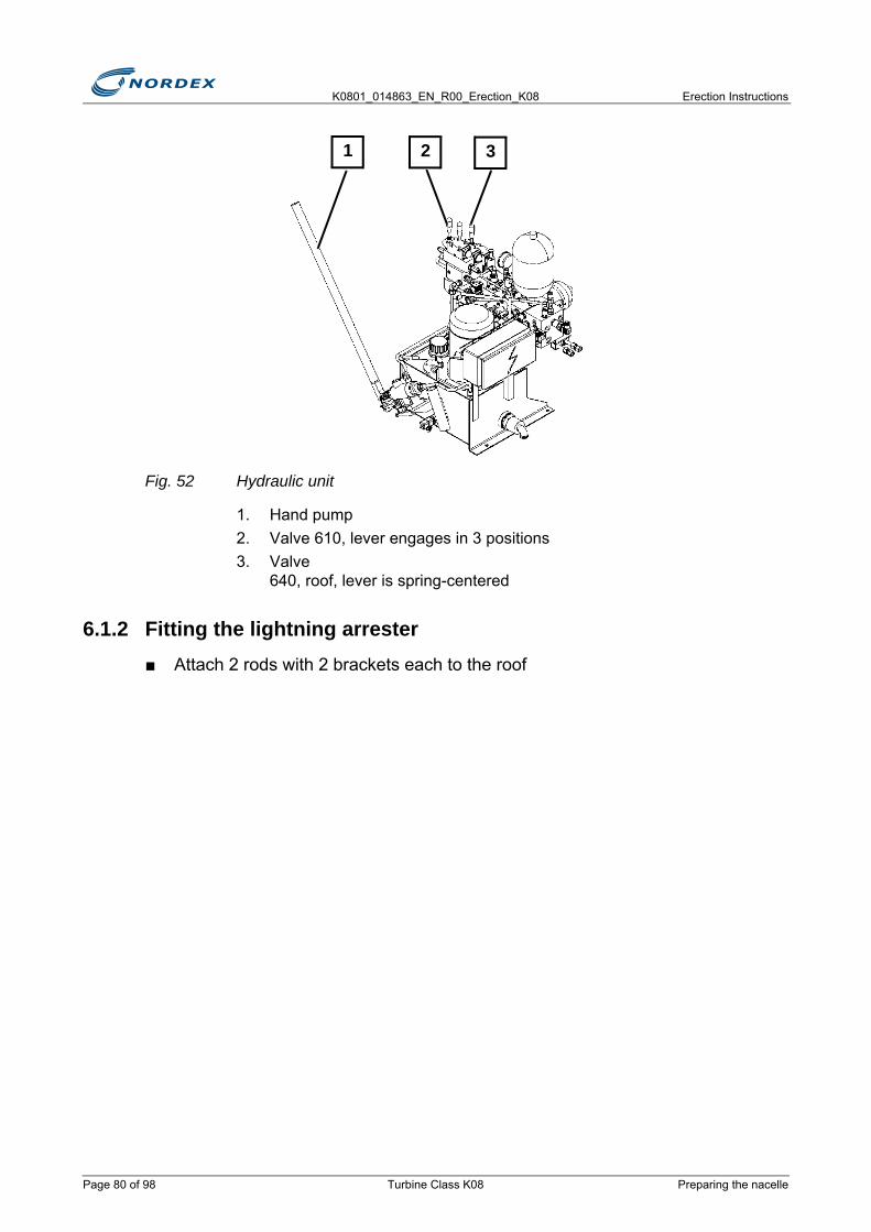
K0801_014863_EN_R00_Erection_K08 Erection Instructions
Fig. 52 Hydraulic unit
1. Hand pump2. Valve 610, lever engages in 3 positions3. Valve
640, roof, lever is spring-centered
6.1.2 Fitting the lightning arrester■ Attach 2 rods with 2 brackets each to the roof
1 2 3
Page 80 of 98 Turbine Class K08 Preparing the nacelle
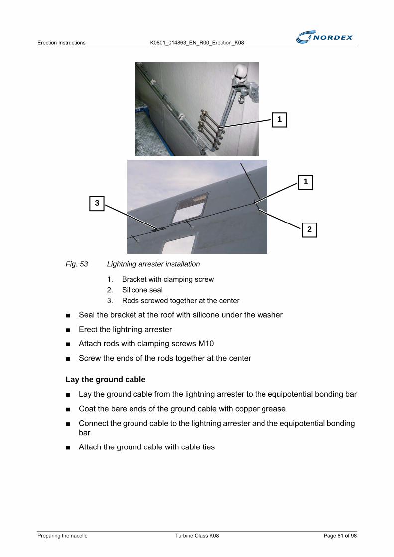
Erection Instructions K0801_014863_EN_R00_Erection_K08
Fig. 53 Lightning arrester installation
1. Bracket with clamping screw2. Silicone seal3. Rods screwed together at the center
■ Seal the bracket at the roof with silicone under the washer
■ Erect the lightning arrester
■ Attach rods with clamping screws M10
■ Screw the ends of the rods together at the center
Lay the ground cable
■ Lay the ground cable from the lightning arrester to the equipotential bonding bar
■ Coat the bare ends of the ground cable with copper grease
■ Connect the ground cable to the lightning arrester and the equipotential bonding bar
■ Attach the ground cable with cable ties
1
3
2
1
Preparing the nacelle Turbine Class K08 Page 81 of 98

K0801_014863_EN_R00_Erection_K08 Erection Instructions
6.1.3 Fitting the air scoopThe air scoop is only fitted to the nacelle at the erection site.
■ Attach the air scoop from the 3 red attachment points on the roof of the air scoop
Fig. 54 Air scoop attachment points
1. Red attachment points to lift the air scoop2. Yellow attachment points for personal protection
■ Lift the air scoop onto the nacelle
LIGHTNING STRIKEImpairment of the functionality of the lightning arrester through electromagnetic interference.
Do not lay the ground cable alongside signal cables.
FALLING LOADFalling air scoop if the attachment points do not have sufficient load capacity.
Use the red attachment points to lift the air scoop.
N O T I C E
WARNING
11
22
Page 82 of 98 Turbine Class K08 Preparing the nacelle
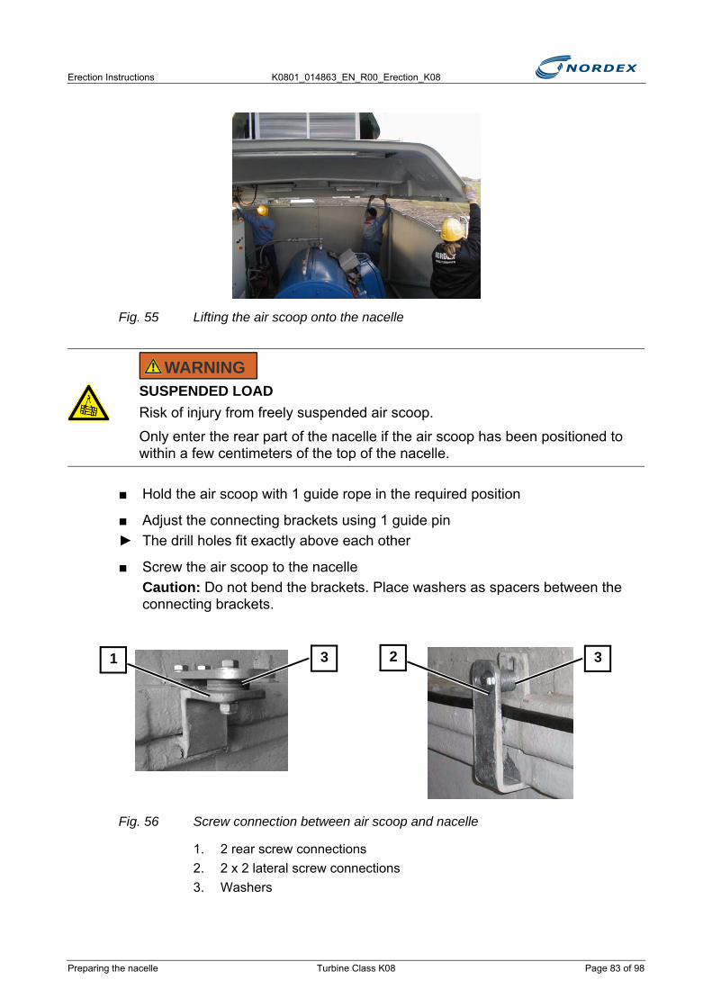
Erection Instructions K0801_014863_EN_R00_Erection_K08
Fig. 55 Lifting the air scoop onto the nacelle
■ Hold the air scoop with 1 guide rope in the required position
■ Adjust the connecting brackets using 1 guide pin► The drill holes fit exactly above each other
■ Screw the air scoop to the nacelleCaution: Do not bend the brackets. Place washers as spacers between the connecting brackets.
Fig. 56 Screw connection between air scoop and nacelle
1. 2 rear screw connections2. 2 x 2 lateral screw connections3. Washers
SUSPENDED LOADRisk of injury from freely suspended air scoop.
Only enter the rear part of the nacelle if the air scoop has been positioned to within a few centimeters of the top of the nacelle.
WARNING
31 32
Preparing the nacelle Turbine Class K08 Page 83 of 98

K0801_014863_EN_R00_Erection_K08 Erection Instructions
Screw connection between air scoop and nacelle
6.1.4 Fitting and connecting the obstacle lights (optional) ■ Fit the obstacle light onto the bracket and the air scoop
■ Connect the obstacle light cable to the corresponding switch cabinet
6.1.5 Fitting and connecting the wind sensors
Fit the wind sensors
Fit 2 different wind sensors to the air scoop
● 2-part wind sensor:- Wind speed sensor- Wind direction sensor
● Ultrasonic wind sensor
Designation Wrench size QuantityHexagon socket screw: M10 x 50 – 8.8 17mm 6
Self-locking hexagon nut: M10 - 10 17mm 6
Washer 10 12
HAZARDOUS VOLTAGEElectric shock resulting from incorrect handling of electrical equipment.
The electrical installation must be carried out by electrical professionals only.
OBSERVE DOCUMENTThe documentation for the obstacle lights is stored with the devices.
DANGER
Page 84 of 98 Turbine Class K08 Preparing the nacelle
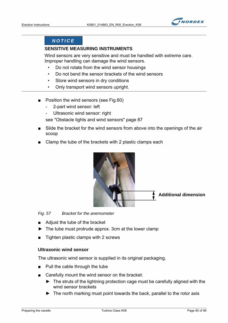
Erection Instructions K0801_014863_EN_R00_Erection_K08
■ Position the wind sensors (see Fig.60)- 2-part wind sensor: left- Ultrasonic wind sensor: rightsee "Obstacle lights and wind sensors" page 87
■ Slide the bracket for the wind sensors from above into the openings of the air scoop
■ Clamp the tube of the brackets with 2 plastic clamps each
Fig. 57 Bracket for the anemometer
■ Adjust the tube of the bracket► The tube must protrude approx. 3cm at the lower clamp
■ Tighten plastic clamps with 2 screws
Ultrasonic wind sensor
The ultrasonic wind sensor is supplied in its original packaging.
■ Pull the cable through the tube
■ Carefully mount the wind sensor on the bracket:► The struts of the lightning protection cage must be carefully aligned with the
wind sensor brackets► The north marking must point towards the back, parallel to the rotor axis
SENSITIVE MEASURING INSTRUMENTSWind sensors are very sensitive and must be handled with extreme care. Improper handling can damage the wind sensors.
• Do not rotate from the wind sensor housings• Do not bend the sensor brackets of the wind sensors • Store wind sensors in dry conditions• Only transport wind sensors upright.
N O T I C E
Additional dimension 3
Preparing the nacelle Turbine Class K08 Page 85 of 98

K0801_014863_EN_R00_Erection_K08 Erection Instructions
Fig. 58 Ultrasonic wind sensor
1. North marking2. Lightning protection cage
2-part wind sensor
■ Loosen 2 screws
■ Adjust the angle by rotating the counter-bracket► The north marking must point towards the back, parallel to the rotor axis
Fig. 59 2-part wind sensor
1. North marking2. Counter-bracket3. 2 screws
SENSITIVE MEASURING INSTRUMENTSDestruction of or damage to the wind sensors from improper handling.
Wind sensors are very sensitive and must be handled with extreme care.
Do not rotate from the wind sensor housings
2
1
N O T I C E
1
3
2
Page 86 of 98 Turbine Class K08 Preparing the nacelle

Erection Instructions K0801_014863_EN_R00_Erection_K08
Check the orientation and position of the wind sensors
► Position of the wind sensors (see Fig.60)- 2-part wind sensor: left- Ultrasonic wind sensor: right
► The north marking of the wind sensors points to the back, exactly parallel to the rotor axis
► The height of the wind sensors: (see Fig.60)
Fig. 60 Obstacle lights and wind sensors
1. 2-part wind sensor2. Ultrasonic wind sensor
Connect the wind sensors
■ Loosen both studs
■ Lay all sensor cables in the nacelle
■ Connect the cable in the top box in accordance with the circuit diagram
■ Connect both brackets of the wind sensors to a lightning protection cable
■ Lay the lightning protection cable from one bracket to the equipotential bonding bar
HAZARDOUS VOLTAGEElectric shock resulting from incorrect handling of electrical equipment.
The electrical installation must be carried out by electrical professionals only.
83 cm102cm
1 2
DANGER
Preparing the nacelle Turbine Class K08 Page 87 of 98

K0801_014863_EN_R00_Erection_K08 Erection Instructions
6.1.6 Fitting the safety railThe safety rail is used as fall protection during the separate drive train assembly until the safety rope has been installed between the rotor bearing and the generator.
■ Undo the roof pole from the top attachment point
■ Always remove the bottom screw of the quick-release fasteners of the roof► The quick-release fastener remains attached to the roof pole
LIGHTNING STRIKEImpairment of the functionality of the lightning arrester through electromagnetic interference.
Lay lightning protection cables at least 0.5 apart from all other signal cables
No cable loops must be present.
DANGER OF FALLINGPersons are unprotected at the open side of the nacelle.
Fit the safety rail for fall protection to the open side of the nacelle.
N O T I C E
DANGER
Page 88 of 98 Turbine Class K08 Preparing the nacelle
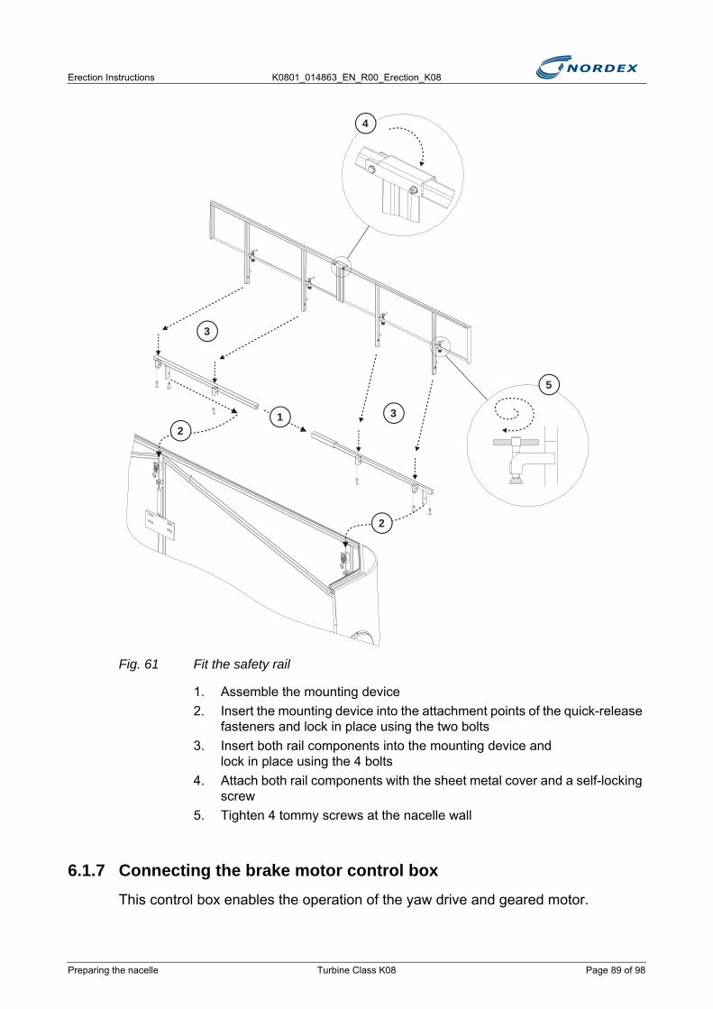
Erection Instructions K0801_014863_EN_R00_Erection_K08
Fig. 61 Fit the safety rail
1. Assemble the mounting device2. Insert the mounting device into the attachment points of the quick-release
fasteners and lock in place using the two bolts3. Insert both rail components into the mounting device and
lock in place using the 4 bolts4. Attach both rail components with the sheet metal cover and a self-locking
screw5. Tighten 4 tommy screws at the nacelle wall
6.1.7 Connecting the brake motor control boxThis control box enables the operation of the yaw drive and geared motor.
3
32
2
1
4
5
Preparing the nacelle Turbine Class K08 Page 89 of 98
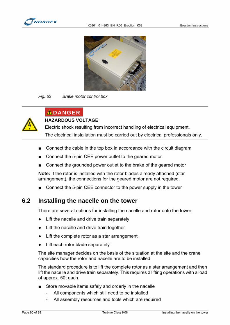
K0801_014863_EN_R00_Erection_K08 Erection Instructions
Fig. 62 Brake motor control box
■ Connect the cable in the top box in accordance with the circuit diagram
■ Connect the 5-pin CEE power outlet to the geared motor
■ Connect the grounded power outlet to the brake of the geared motor
Note: If the rotor is installed with the rotor blades already attached (star arrangement), the connections for the geared motor are not required.
■ Connect the 5-pin CEE connector to the power supply in the tower
6.2 Installing the nacelle on the towerThere are several options for installing the nacelle and rotor onto the tower:
● Lift the nacelle and drive train separately
● Lift the nacelle and drive train together
● Lift the complete rotor as a star arrangement
● Lift each rotor blade separately
The site manager decides on the basis of the situation at the site and the crane capacities how the rotor and nacelle are to be installed.
The standard procedure is to lift the complete rotor as a star arrangement and then lift the nacelle and drive train separately. This requires 3 lifting operations with a load of approx. 50t each.
■ Store movable items safely and orderly in the nacelle- All components which still need to be installed- All assembly resources and tools which are required
HAZARDOUS VOLTAGEElectric shock resulting from incorrect handling of electrical equipment.
The electrical installation must be carried out by electrical professionals only.
DANGER
Page 90 of 98 Turbine Class K08 Installing the nacelle on the tower
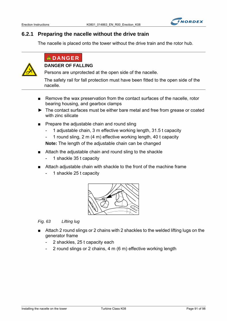
Erection Instructions K0801_014863_EN_R00_Erection_K08
6.2.1 Preparing the nacelle without the drive trainThe nacelle is placed onto the tower without the drive train and the rotor hub.
■ Remove the wax preservation from the contact surfaces of the nacelle, rotor bearing housing, and gearbox clamps
► The contact surfaces must be either bare metal and free from grease or coated with zinc silicate
■ Prepare the adjustable chain and round sling- 1 adjustable chain, 3 m effective working length, 31.5 t capacity- 1 round sling, 2 m (4 m) effective working length, 40 t capacityNote: The length of the adjustable chain can be changed
■ Attach the adjustable chain and round sling to the shackle- 1 shackle 35 t capacity
■ Attach adjustable chain with shackle to the front of the machine frame- 1 shackle 25 t capacity
Fig. 63 Lifting lug
■ Attach 2 round slings or 2 chains with 2 shackles to the welded lifting lugs on the generator frame- 2 shackles, 25 t capacity each- 2 round slings or 2 chains, 4 m (6 m) effective working length
DANGER OF FALLINGPersons are unprotected at the open side of the nacelle.
The safety rail for fall protection must have been fitted to the open side of the nacelle.
DANGER
Installing the nacelle on the tower Turbine Class K08 Page 91 of 98
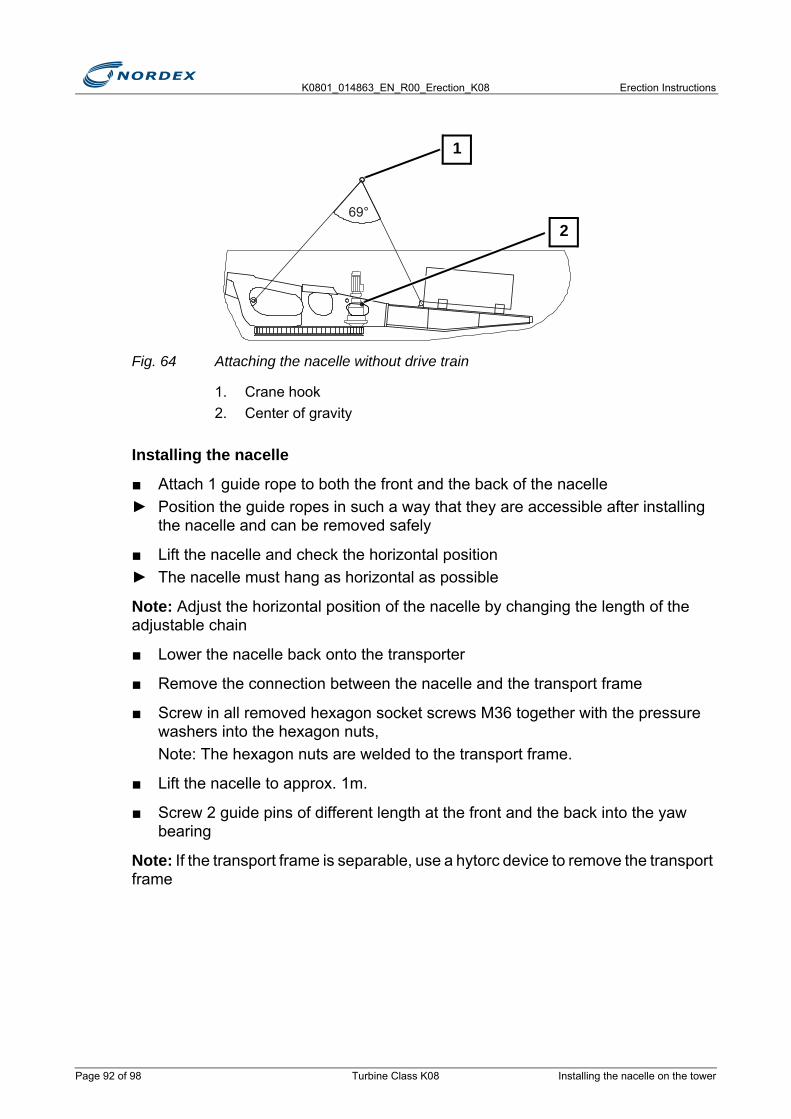
K0801_014863_EN_R00_Erection_K08 Erection Instructions
Fig. 64 Attaching the nacelle without drive train
1. Crane hook2. Center of gravity
Installing the nacelle
■ Attach 1 guide rope to both the front and the back of the nacelle► Position the guide ropes in such a way that they are accessible after installing
the nacelle and can be removed safely
■ Lift the nacelle and check the horizontal position► The nacelle must hang as horizontal as possible
Note: Adjust the horizontal position of the nacelle by changing the length of the adjustable chain
■ Lower the nacelle back onto the transporter
■ Remove the connection between the nacelle and the transport frame
■ Screw in all removed hexagon socket screws M36 together with the pressure washers into the hexagon nuts, Note: The hexagon nuts are welded to the transport frame.
■ Lift the nacelle to approx. 1m.
■ Screw 2 guide pins of different length at the front and the back into the yaw bearing
Note: If the transport frame is separable, use a hytorc device to remove the transport frame
69°
1
2
Page 92 of 98 Turbine Class K08 Installing the nacelle on the tower
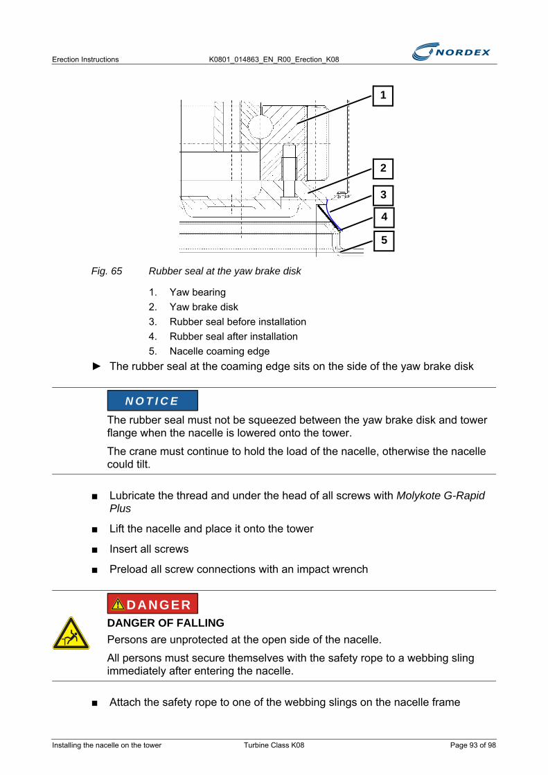
Erection Instructions K0801_014863_EN_R00_Erection_K08
Fig. 65 Rubber seal at the yaw brake disk
1. Yaw bearing2. Yaw brake disk3. Rubber seal before installation4. Rubber seal after installation5. Nacelle coaming edge
► The rubber seal at the coaming edge sits on the side of the yaw brake disk
■ Lubricate the thread and under the head of all screws with Molykote G-Rapid Plus
■ Lift the nacelle and place it onto the tower
■ Insert all screws
■ Preload all screw connections with an impact wrench
■ Attach the safety rope to one of the webbing slings on the nacelle frame
The rubber seal must not be squeezed between the yaw brake disk and tower flange when the nacelle is lowered onto the tower.
The crane must continue to hold the load of the nacelle, otherwise the nacelle could tilt.
DANGER OF FALLINGPersons are unprotected at the open side of the nacelle.
All persons must secure themselves with the safety rope to a webbing sling immediately after entering the nacelle.
1
2
3
5
4
N O T I C E
DANGER
Installing the nacelle on the tower Turbine Class K08 Page 93 of 98
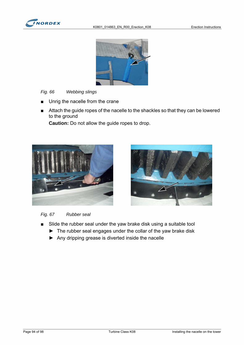
K0801_014863_EN_R00_Erection_K08 Erection Instructions
Fig. 66 Webbing slings
■ Unrig the nacelle from the crane
■ Attach the guide ropes of the nacelle to the shackles so that they can be lowered to the groundCaution: Do not allow the guide ropes to drop.
Fig. 67 Rubber seal
■ Slide the rubber seal under the yaw brake disk using a suitable tool ► The rubber seal engages under the collar of the yaw brake disk ► Any dripping grease is diverted inside the nacelle
Page 94 of 98 Turbine Class K08 Installing the nacelle on the tower
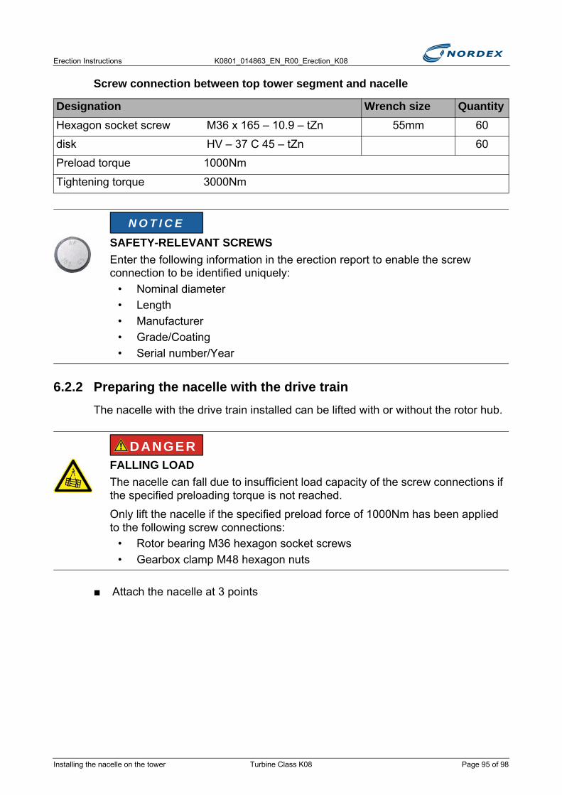
Erection Instructions K0801_014863_EN_R00_Erection_K08
Screw connection between top tower segment and nacelle
6.2.2 Preparing the nacelle with the drive trainThe nacelle with the drive train installed can be lifted with or without the rotor hub.
■ Attach the nacelle at 3 points
Designation Wrench size QuantityHexagon socket screw M36 x 165 – 10.9 – tZn 55mm 60
disk HV – 37 C 45 – tZn 60
Preload torque 1000Nm
Tightening torque 3000Nm
SAFETY-RELEVANT SCREWSEnter the following information in the erection report to enable the screw connection to be identified uniquely:
• Nominal diameter• Length• Manufacturer• Grade/Coating• Serial number/Year
FALLING LOADThe nacelle can fall due to insufficient load capacity of the screw connections if the specified preloading torque is not reached.
Only lift the nacelle if the specified preload force of 1000Nm has been applied to the following screw connections:
• Rotor bearing M36 hexagon socket screws • Gearbox clamp M48 hexagon nuts
N O T I C E
DANGER
Installing the nacelle on the tower Turbine Class K08 Page 95 of 98
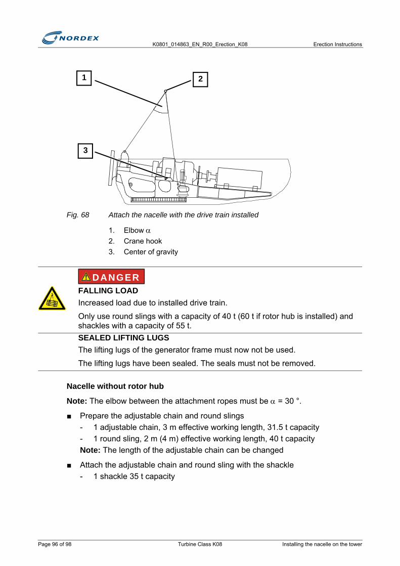
K0801_014863_EN_R00_Erection_K08 Erection Instructions
Fig. 68 Attach the nacelle with the drive train installed
1. Elbow α2. Crane hook3. Center of gravity
Nacelle without rotor hub
Note: The elbow between the attachment ropes must be α = 30 °.
■ Prepare the adjustable chain and round slings- 1 adjustable chain, 3 m effective working length, 31.5 t capacity- 1 round sling, 2 m (4 m) effective working length, 40 t capacityNote: The length of the adjustable chain can be changed
■ Attach the adjustable chain and round sling with the shackle- 1 shackle 35 t capacity
FALLING LOADIncreased load due to installed drive train.
Only use round slings with a capacity of 40 t (60 t if rotor hub is installed) and shackles with a capacity of 55 t.SEALED LIFTING LUGSThe lifting lugs of the generator frame must now not be used.
The lifting lugs have been sealed. The seals must not be removed.
2
3
1
WARNINGDANGER
Page 96 of 98 Turbine Class K08 Installing the nacelle on the tower

Erection Instructions K0801_014863_EN_R00_Erection_K08
■ Attach the nacelle using the shackle and the lifting lug on the rotor bearing housing- Adjustable chain with round sling- 1 shackle, 55 t capacity
■ Attach nacelle to 2 lifting lugs on the machine frame- 2 round slings, 2 m (4 m) effectiving working length, 40 t capacity each- 2 shackles, 55 t capacity each
Fig. 69 Lifting lug on the rotor bearing housing
Nacelle with rotor hub
Note: Elbow between attachment ropes must be α = 33 °
■ Attach lifting tackle nacelle with rotor hub to the lifting lug on the rotor bearing housing and to the rotor lock disk
Fig. 70 Lifting tackle: Nacelle with rotor hub
■ Attach the following to the lifting tackle nacelle with rotor hub- 1 round sling, 2 m (4 m) effective working length, 40 t capacity Note: Double up the round sling if necessary- Adjustable chain, 45 t capacity- Shackle with collar, 75 t capacity
Installing the nacelle on the tower Turbine Class K08 Page 97 of 98
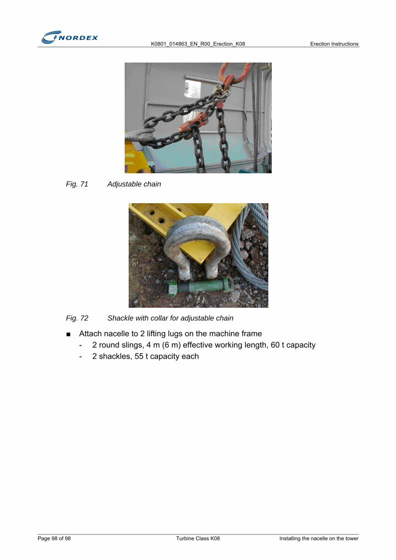
K0801_014863_EN_R00_Erection_K08 Erection Instructions
Fig. 71 Adjustable chain
Fig. 72 Shackle with collar for adjustable chain
■ Attach nacelle to 2 lifting lugs on the machine frame- 2 round slings, 4 m (6 m) effective working length, 60 t capacity- 2 shackles, 55 t capacity each
Page 98 of 98 Turbine Class K08 Installing the nacelle on the tower

Erection Instructions K0801_014863_EN_R00_Erection_K08
7. Nacelle completionTo complete the nacelle the following tasks need to be carried out:
● Completing the hydraulic system
● Inspecting the rotor brake at the rotor brake disk
● Assembling the individual components- Assemble the yaw drive cam limit switch- Assemble the automatic rotor bearing lubrication system- Seal the lifting lugs- Fit the oil overflow- Fit the fire extinguisher
● Assembling the coupling- Link coupling- Multi-disk coupling
● Aligning the generator
● Checking the generator alignment- Fixturlaser alignment system- Set dial gage
● Adjusting and screwing on the generator elastomer bearings
● Completing the gearbox cooling circuit
● Assembling the guard for the coupling
● Commissioning and testing the rotor brake
● Completing the generator cooling circuit
● Securing the on-board crane
7.1 Completing the hydraulic systemThe rotor brake is disconnected from the hydraulic circuit for the separate transport of the nacelle and the drive train. After assembly of the nacelle and drive train the rotor brake is reconnected.
Completing the hydraulic system Turbine Class K08 Page 99 of 126

K0801_014863_EN_R00_Erection_K08 Erection Instructions
Abb. 73 Hydraulic pipes
1. Connection for the pressure hose to the rotor brake2. Connection for the oil leakage hose
■ Connect the pressure hose for the rotor brake to the left inside hydraulic pipe
■ Connect the oil leakage hose to the right outside hydraulic pipe
7.2 Inspecting the rotor brake at the rotor brake disk■ Check the rotor lock bolt in all 3 drill holes:
► The rotor lock bolt can easily be inserted through both brake calipers and the rotor brake disk
► The rotor lock bolt can be secured with the spring cotter
■ Secure the rotor lock bolt in the bracket with the spring cotter
ROTATING COMPONENTSRisk of injury from rotating components.
Only lock the rotor using the rotor brake under the following conditions:• Wind velocity is below 12m/s• Rotor has been stopped prior to being locked• Rotor brake has been applied with holding pressure• It is not permitted to leave the WT while the rotor is locked at the rotor brake
disk.• Do not carry out any work on the following components:
- Rotor hub- Rotor brake- Torque-transmitting components and their bearing seats
• Rotor blades are in the feathering position• Do not pitch the rotor blades
21
WARNING
Page 100 of 126 Turbine Class K08 Inspecting the rotor brake at the rotor brake disk

Erection Instructions K0801_014863_EN_R00_Erection_K08
Adjust the rotor brake disk:
■ Check and adjust the clearance between the rotor brake disk and the brake pads
Abb. 74 Adjust the clearance
1. Adjustment screw2. Locknut
■ Undo the locknut
■ Adjust the adjustment screw► The clearance is the same on both sides
■ Tighten the locknut► The rotor brake disk runs freely and centered between the brake pads
■ Apply the rotor brake several times
■ Vent the rotor brake at the highest point above the miniature test port
Note: Vent using the manual lever at the hydraulic unit.
■ Remove preservation from the rotor brake disk
Caution: The brake pads must not be contaminated with protective wax.
7.3 Assembling the individual components
7.3.1 Assemble the yaw drive cam limit switch
The yaw drive cam limit switch has been preassembled in the front left opening of the nacelle; assembly is completed during commissioning.
1
2
Assembling the individual components Turbine Class K08 Page 101 of 126
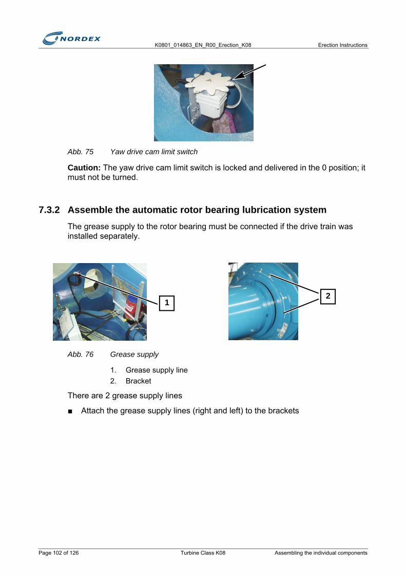
K0801_014863_EN_R00_Erection_K08 Erection Instructions
Abb. 75 Yaw drive cam limit switch
Caution: The yaw drive cam limit switch is locked and delivered in the 0 position; it must not be turned.
7.3.2 Assemble the automatic rotor bearing lubrication systemThe grease supply to the rotor bearing must be connected if the drive train was installed separately.
Abb. 76 Grease supply
1. Grease supply line2. Bracket
There are 2 grease supply lines
■ Attach the grease supply lines (right and left) to the brackets
12
Page 102 of 126 Turbine Class K08 Assembling the individual components
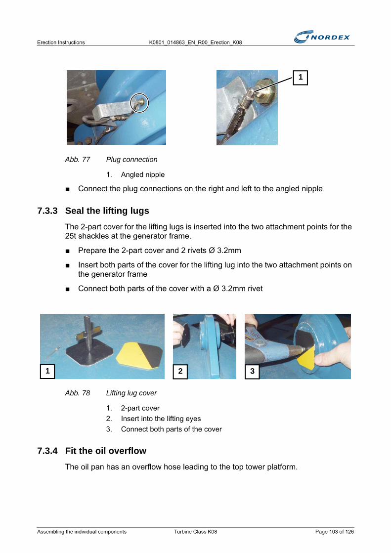
Erection Instructions K0801_014863_EN_R00_Erection_K08
Abb. 77 Plug connection
1. Angled nipple
■ Connect the plug connections on the right and left to the angled nipple
7.3.3 Seal the lifting lugsThe 2-part cover for the lifting lugs is inserted into the two attachment points for the 25t shackles at the generator frame.
■ Prepare the 2-part cover and 2 rivets Ø 3.2mm
■ Insert both parts of the cover for the lifting lug into the two attachment points on the generator frame
■ Connect both parts of the cover with a Ø 3.2mm rivet
Abb. 78 Lifting lug cover
1. 2-part cover2. Insert into the lifting eyes3. Connect both parts of the cover
7.3.4 Fit the oil overflowThe oil pan has an overflow hose leading to the top tower platform.
1
1 2 3
Assembling the individual components Turbine Class K08 Page 103 of 126
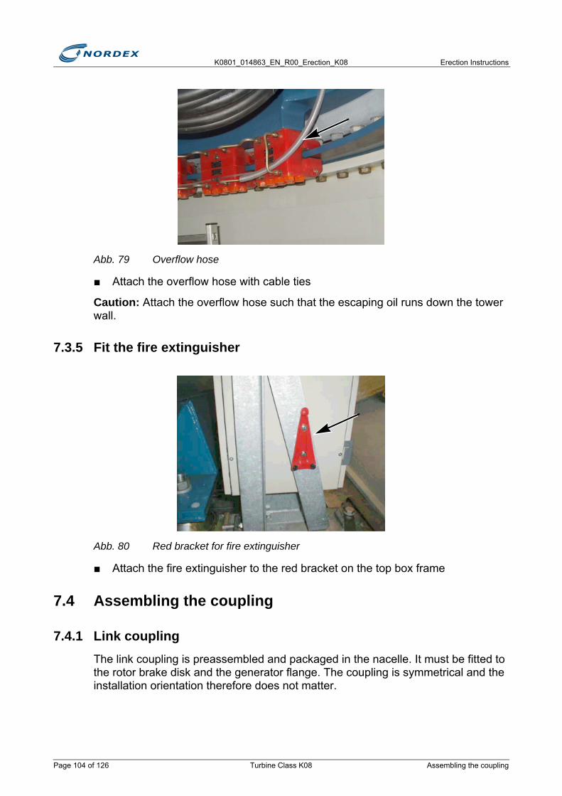
K0801_014863_EN_R00_Erection_K08 Erection Instructions
Abb. 79 Overflow hose
■ Attach the overflow hose with cable ties
Caution: Attach the overflow hose such that the escaping oil runs down the tower wall.
7.3.5 Fit the fire extinguisher
Abb. 80 Red bracket for fire extinguisher
■ Attach the fire extinguisher to the red bracket on the top box frame
7.4 Assembling the coupling
7.4.1 Link couplingThe link coupling is preassembled and packaged in the nacelle. It must be fitted to the rotor brake disk and the generator flange. The coupling is symmetrical and the installation orientation therefore does not matter.
Page 104 of 126 Turbine Class K08 Assembling the coupling
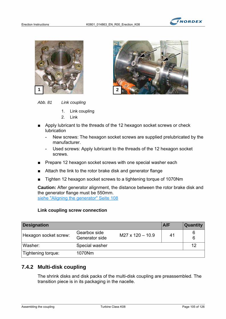
Erection Instructions K0801_014863_EN_R00_Erection_K08
Abb. 81 Link coupling
1. Link coupling2. Link
■ Apply lubricant to the threads of the 12 hexagon socket screws or check lubrication- New screws: The hexagon socket screws are supplied prelubricated by the
manufacturer.- Used screws: Apply lubricant to the threads of the 12 hexagon socket
screws.
■ Prepare 12 hexagon socket screws with one special washer each
■ Attach the link to the rotor brake disk and generator flange
■ Tighten 12 hexagon socket screws to a tightening torque of 1070Nm
Caution: After generator alignment, the distance between the rotor brake disk and the generator flange must be 550mm. siehe "Aligning the generator" Seite 108
Link coupling screw connection
7.4.2 Multi-disk couplingThe shrink disks and disk packs of the multi-disk coupling are preassembled. The transition piece is in its packaging in the nacelle.
Designation A/F Quantity
Hexagon socket screw: Gearbox side Generator side M27 x 120 – 10.9 41 6
6
Washer: Special washer 12
Tightening torque: 1070Nm
1 2
Assembling the coupling Turbine Class K08 Page 105 of 126
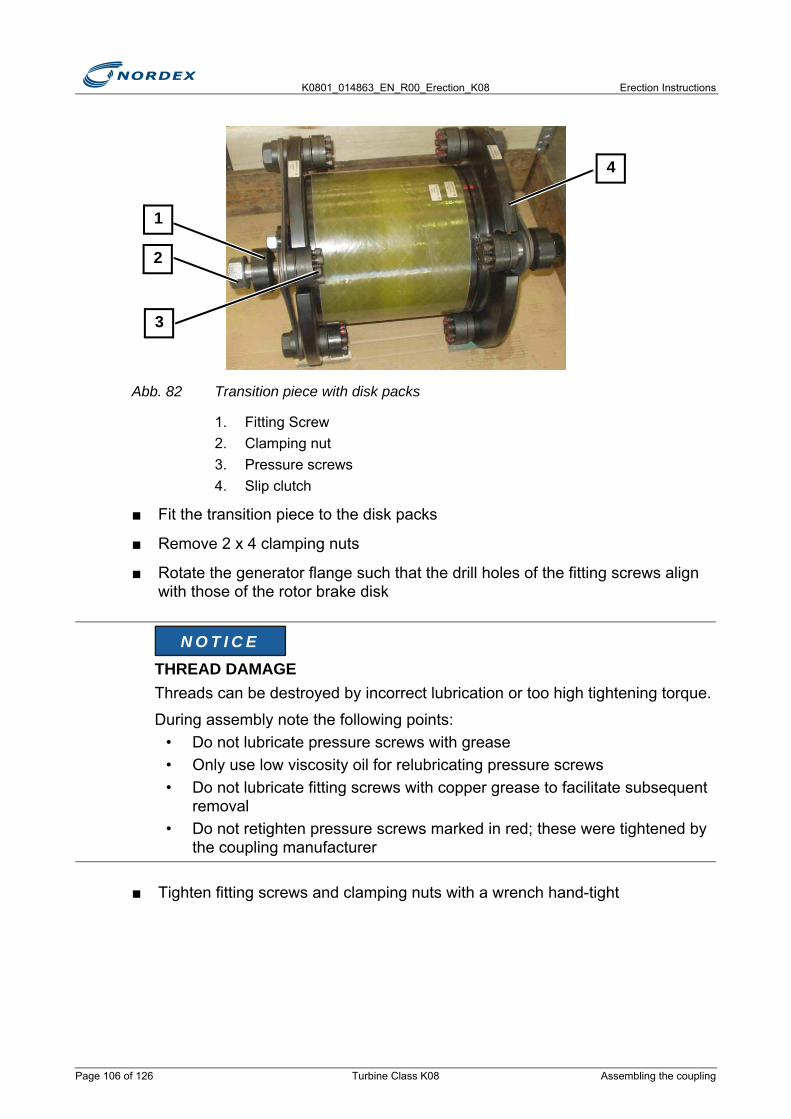
K0801_014863_EN_R00_Erection_K08 Erection Instructions
Abb. 82 Transition piece with disk packs
1. Fitting Screw2. Clamping nut3. Pressure screws4. Slip clutch
■ Fit the transition piece to the disk packs
■ Remove 2 x 4 clamping nuts
■ Rotate the generator flange such that the drill holes of the fitting screws align with those of the rotor brake disk
■ Tighten fitting screws and clamping nuts with a wrench hand-tight
THREAD DAMAGEThreads can be destroyed by incorrect lubrication or too high tightening torque.
During assembly note the following points:• Do not lubricate pressure screws with grease• Only use low viscosity oil for relubricating pressure screws• Do not lubricate fitting screws with copper grease to facilitate subsequent
removal• Do not retighten pressure screws marked in red; these were tightened by
the coupling manufacturer
2
1
3
4
N O T I C E
Page 106 of 126 Turbine Class K08 Assembling the coupling

Erection Instructions K0801_014863_EN_R00_Erection_K08
Abb. 83 Rotor brake disk
1. Drill holes for fitting screws
■ During assembly note the following points:► The slip clutch is fitted to the generator side ► All components make contact without any gaps► The pressure screws in the clamping nuts do not protrude on the pressure
side
■ Unscrew 4 clamping nuts by a quarter turn► Clearance: approx. 1mm
Abb. 84 Pressure screws
1. Clearance2. Tighten 4 pressure screws crosswise3. Tighten all pressure screws to the tightening torque4. Head contact surface
■ Tighten 4 opposite pressure screws crosswise- First hand-tight - Then to 50Nm - Then to 90Nm
1
4321
approx. 1mm
Assembling the coupling Turbine Class K08 Page 107 of 126
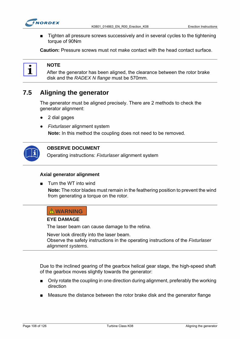
K0801_014863_EN_R00_Erection_K08 Erection Instructions
■ Tighten all pressure screws successively and in several cycles to the tightening torque of 90Nm
Caution: Pressure screws must not make contact with the head contact surface.
7.5 Aligning the generatorThe generator must be aligned precisely. There are 2 methods to check the generator alignment:
● 2 dial gages
● Fixturlaser alignment systemNote: In this method the coupling does not need to be removed.
Axial generator alignment
■ Turn the WT into windNote: The rotor blades must remain in the feathering position to prevent the wind from generating a torque on the rotor.
Due to the inclined gearing of the gearbox helical gear stage, the high-speed shaft of the gearbox moves slightly towards the generator:
■ Only rotate the coupling in one direction during alignment, preferably the working direction
■ Measure the distance between the rotor brake disk and the generator flange
NOTEAfter the generator has been aligned, the clearance between the rotor brake disk and the RADEX N flange must be 570mm.
OBSERVE DOCUMENTOperating instructions: Fixturlaser alignment system
EYE DAMAGEThe laser beam can cause damage to the retina.
Never look directly into the laser beam. Observe the safety instructions in the operating instructions of the Fixturlaser alignment systems.
WARNING
Page 108 of 126 Turbine Class K08 Aligning the generator
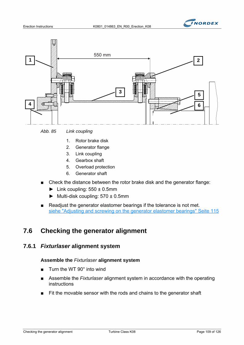
Erection Instructions K0801_014863_EN_R00_Erection_K08
Abb. 85 Link coupling
1. Rotor brake disk2. Generator flange3. Link coupling4. Gearbox shaft5. Overload protection6. Generator shaft
■ Check the distance between the rotor brake disk and the generator flange:► Link coupling: 550 ± 0.5mm► Multi-disk coupling: 570 ± 0.5mm
■ Readjust the generator elastomer bearings if the tolerance is not met. siehe "Adjusting and screwing on the generator elastomer bearings" Seite 115
7.6 Checking the generator alignment
7.6.1 Fixturlaser alignment system
Assemble the Fixturlaser alignment system
■ Turn the WT 90° into wind
■ Assemble the Fixturlaser alignment system in accordance with the operating instructions
■ Fit the movable sensor with the rods and chains to the generator shaft
550 mm
3
4
1
5
2
6
Checking the generator alignment Turbine Class K08 Page 109 of 126
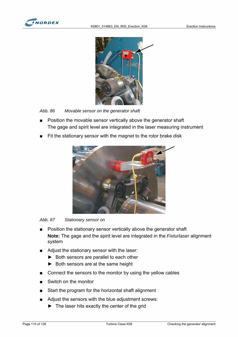
K0801_014863_EN_R00_Erection_K08 Erection Instructions
Abb. 86 Movable sensor on the generator shaft
■ Position the movable sensor vertically above the generator shaftThe gage and spirit level are integrated in the laser measuring instrument
■ Fit the stationary sensor with the magnet to the rotor brake disk
Abb. 87 Stationary sensor on
■ Position the stationary sensor vertically above the generator shaftNote: The gage and the spirit level are integrated in the Fixturlaser alignment system
■ Adjust the stationary sensor with the laser:► Both sensors are parallel to each other► Both sensors are at the same height
■ Connect the sensors to the monitor by using the yellow cables
■ Switch on the monitor
■ Start the program for the horizontal shaft alignment
■ Adjust the sensors with the blue adjustment screws:► The laser hits exactly the center of the grid
Page 110 of 126 Turbine Class K08 Checking the generator alignment

Erection Instructions K0801_014863_EN_R00_Erection_K08
Enter data
■ Check the system settings:- Measuring unit mm- Automatic switch-off: e.g. after 15 minutes- Enter the current time and current date
■ Measure the required dimensions A to D ► The distance C between the generator elastomer bearings is 1400mm
■ Set resolution to 0.01Note: The resolution of 0.01 has been preset
■ Set measuring duration to 3 secondsNote: The measuring duration of 3 seconds has been preset
■ Set the monitor filter to 0Note: The monitor filter has been preset to 0
■ Set the measuring method Tripoint
Measurement
■ Carry out the measurement at 3 points (Tripoint)
■ Rotate the generator shaft by at least 30° for each subsequent measurement
■ Save one measurement before and after adjustment
Modify the measuring position
■ Release the rotor brake
NOTEIn gusty/windy conditions the measuring duration must be 10 seconds.
NOTEThe rotor brake must be applied during each measurement.
ROTATING ROTORUncontrolled rotor rotation due to the rotor brake not being applied.
Personnel must be able to brake the drive train in an emergency.
CAUTION
Checking the generator alignment Turbine Class K08 Page 111 of 126

K0801_014863_EN_R00_Erection_K08 Erection Instructions
■ Save the results in this format: - Example: 8010.ibn.before.10
XXXX. Ibn. before. YY
■ Tighten the screw connection between the generator elastomer bearings and the generator frame to a tightening torque of 170N
■ Carry out a test measurement
■ Record the values within the tolerance in the Erection Report Example: 8010.ibn.after.12
■ Readjust the generator elastomer bearings if the tolerance is not met. siehe "Adjusting and screwing on the generator elastomer bearings" Seite 115
Record the results
■ Record the results in the Erection Report
■ Remove the Fixturlaser alignment system
■ Store the Fixturlaser alignment system in the carry case
Tolerances for the generator offset of both coupling types
7.6.2 Set dial gage■ Remove 2 hexagon socket screws M27 from the rotor brake disk
Note: Rod attachment in the rod coupling
■ Attach the tightening device for the stand(s) using the 2 holes
OBSERVE DOCUMENTOperating instructions: Fixturlaser alignment system
XXXX Turbine number
Ibn Start-up
Before Before adjustment
YY Average value
Axial offset ± 0.5mm
Parallel offset ± 0.5mm
Angular offset ± 0.2mm/100mm
Page 112 of 126 Turbine Class K08 Checking the generator alignment
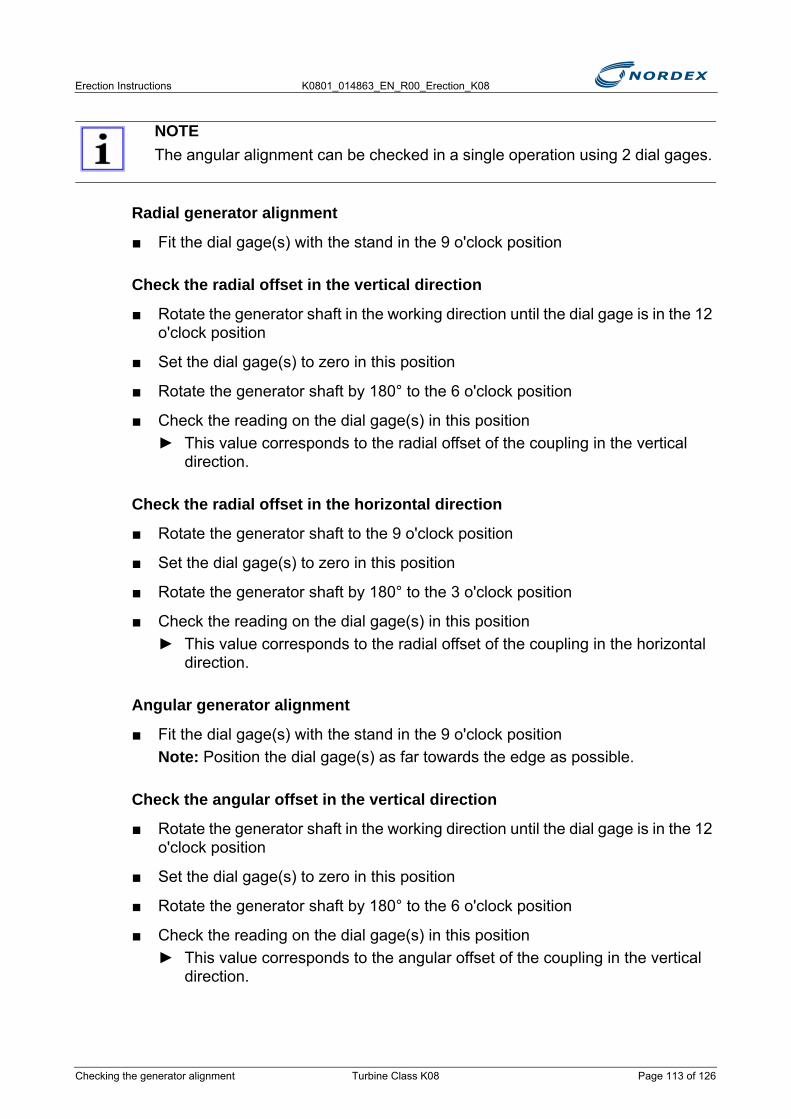
Erection Instructions K0801_014863_EN_R00_Erection_K08
Radial generator alignment
■ Fit the dial gage(s) with the stand in the 9 o'clock position
Check the radial offset in the vertical direction
■ Rotate the generator shaft in the working direction until the dial gage is in the 12 o'clock position
■ Set the dial gage(s) to zero in this position
■ Rotate the generator shaft by 180° to the 6 o'clock position
■ Check the reading on the dial gage(s) in this position► This value corresponds to the radial offset of the coupling in the vertical
direction.
Check the radial offset in the horizontal direction
■ Rotate the generator shaft to the 9 o'clock position
■ Set the dial gage(s) to zero in this position
■ Rotate the generator shaft by 180° to the 3 o'clock position
■ Check the reading on the dial gage(s) in this position► This value corresponds to the radial offset of the coupling in the horizontal
direction.
Angular generator alignment
■ Fit the dial gage(s) with the stand in the 9 o'clock positionNote: Position the dial gage(s) as far towards the edge as possible.
Check the angular offset in the vertical direction
■ Rotate the generator shaft in the working direction until the dial gage is in the 12 o'clock position
■ Set the dial gage(s) to zero in this position
■ Rotate the generator shaft by 180° to the 6 o'clock position
■ Check the reading on the dial gage(s) in this position► This value corresponds to the angular offset of the coupling in the vertical
direction.
NOTEThe angular alignment can be checked in a single operation using 2 dial gages.
Checking the generator alignment Turbine Class K08 Page 113 of 126
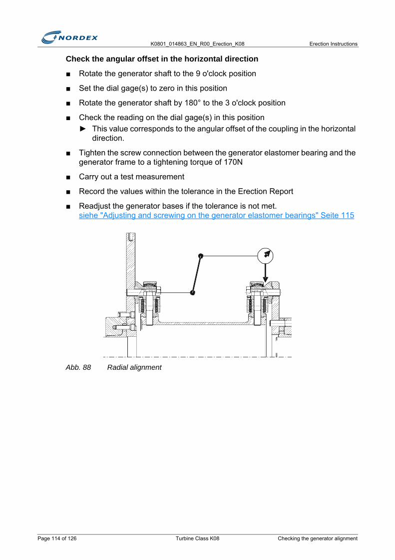
K0801_014863_EN_R00_Erection_K08 Erection Instructions
Check the angular offset in the horizontal direction
■ Rotate the generator shaft to the 9 o'clock position
■ Set the dial gage(s) to zero in this position
■ Rotate the generator shaft by 180° to the 3 o'clock position
■ Check the reading on the dial gage(s) in this position► This value corresponds to the angular offset of the coupling in the horizontal
direction.
■ Tighten the screw connection between the generator elastomer bearing and the generator frame to a tightening torque of 170N
■ Carry out a test measurement
■ Record the values within the tolerance in the Erection Report
■ Readjust the generator bases if the tolerance is not met. siehe "Adjusting and screwing on the generator elastomer bearings" Seite 115
Abb. 88 Radial alignment
Page 114 of 126 Turbine Class K08 Checking the generator alignment
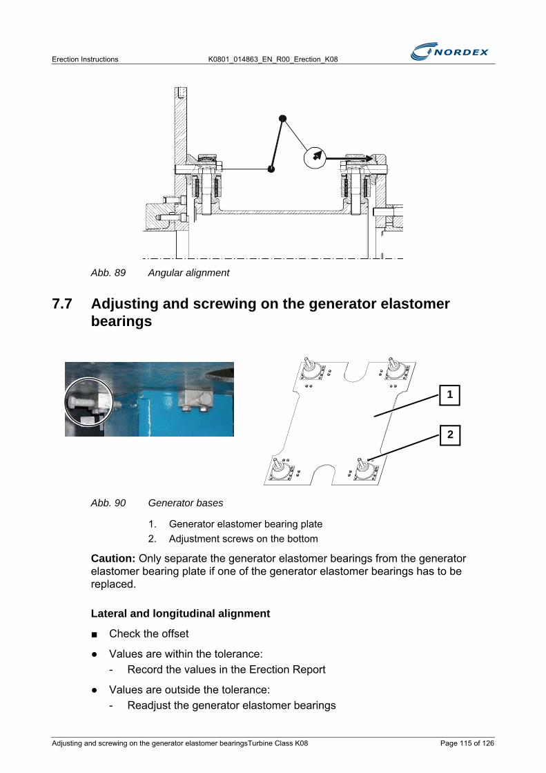
Erection Instructions K0801_014863_EN_R00_Erection_K08
Abb. 89 Angular alignment
7.7 Adjusting and screwing on the generator elastomer bearings
Abb. 90 Generator bases
1. Generator elastomer bearing plate2. Adjustment screws on the bottom
Caution: Only separate the generator elastomer bearings from the generator elastomer bearing plate if one of the generator elastomer bearings has to be replaced.
Lateral and longitudinal alignment
■ Check the offset
● Values are within the tolerance:- Record the values in the Erection Report
● Values are outside the tolerance:- Readjust the generator elastomer bearings
1
2
Adjusting and screwing on the generator elastomer bearingsTurbine Class K08 Page 115 of 126

K0801_014863_EN_R00_Erection_K08 Erection Instructions
■ Screw the adjustment screws under the generator elastomer bearing plate to the generator frameNote: This prevents slipping
■ Undo 4 hexagon socket screws M16 per generator elastomer bearing
■ Align the generator elastomer bearing plate by using the adjusting screws
■ Check the offset again
● Values are within the tolerance:- Tighten 4 hexagon socket screws M16 between the generator elastomer
bearing and the generator frame to a tightening torque of 170N- Record the values in the Erection Report
● Values are outside the tolerance:- Readjust the generator elastomer bearings
■ Repeat the procedure until all values are within the tolerance
Height adjustment
Caution: Take the load off the generator bearing during height adjustment otherwise the fine thread can be destroyed.
■ Check the offset
● Values are within the tolerance:- Record the values in the Erection Report
● Values are outside the tolerance:- Readjust the generator elastomer bearings
Abb. 91 Generator elastomer bearing
1. Generator elastomer bearing housing2. Hexagon nut M363. Adjustment nut
10
3
2
1
Page 116 of 126 Turbine Class K08 Adjusting and screwing on the generator elastomer bea-
Erection Instructions K0801_014863_EN_R00_Erection_K08
■ Stop the generator from sliding backwards by using a chain winch
■ Undo all hexagon nuts M36 at the generator elastomer bearings
Take the load off the generator
■ Slightly lift the generator with a crane or hydraulic lifting device
■ Slide the lifting device with load distribution, e.g. bridge, under the generator into the U recess in the generator elastomer bearing plate
■ Take the load off both elastomer bearings at the front and the back simultaneouslyNote: Place a small hydraulic cylinder at each generator elastomer bearing between the generator elastomer bearing plate and the leveling plate of the generator
■ Align the generator in height
■ Lower the generator
■ Check the offset again
● Values are within the tolerance:- Tighten 4 hexagon socket screws M36 between the generator elastomer
bearing and the generator to a tightening torque of 1900N- Record the values in the Erection Report
● Values are outside the tolerance:- Readjust the generator elastomer bearings again
■ Repeat the procedure until all values are within the tolerance
■ Remove the chain winch
NOTEThe distance between the generator elastomer bearing housing and the adjustment nut must not exceed 10mm.
Use 2mm or 5mm shims.
Adjusting and screwing on the generator elastomer bearingsTurbine Class K08 Page 117 of 126
K0801_014863_EN_R00_Erection_K08 Erection Instructions
Screw connection generator elastomer bearing/generator
Screw connection generator elastomer bearing/generator frame
Screw connection generator elastomer bearing/generator elastomer bearing plate
Caution: Only undo these screws if one of the generator elastomer bearings has to be replaced.
7.8 Completing the gearbox cooling circuitThe gearbox cooling circuit must be completed if the cooling circuit of the gearbox had been disconnected to transport the nacelle and drive train.
Connect the cooling hoses for the flow and return to the oil filter
■ Remove the blanking plug
■ Attach the lower cooling hose to the T fitting
■ Attach the upper cooling hose with pipe elbow to the top outlet of the oil filter
Designation Wrench size QuantityHexagon nut: ISO 4032 – M36– 8 – tZn 55mm 4
Tightening torque: 1900Nm
Designation Wrench size QuantityHexagon socket screw: ISO 4014 – M16 x 70 – 8.8 – tZn 24mm 16
Hexagon nut: ISO 4032 – M16 – 8 – tZn 24mm 16
Washer: ISO 7090 – 16 – 200 HV 50
Tightening torque: 170Nm
Designation Wrench size QuantityHexagon nut: ISO 4032 – M10 x 20 – 8.8 – tZn 17mm 16
Tightening torque: 41Nm
Page 118 of 126 Turbine Class K08 Completing the gearbox cooling circuit

Erection Instructions K0801_014863_EN_R00_Erection_K08
Abb. 92 Cooling hoses
1. Oil filter2. Upper cooling hose lower cooling hose at the T fitting
■ Tighten the hexagon nut with a wrench hand-tight► The screw connections are tightly sealed
7.9 Assembling the guard for the couplingThe guard for the coupling consists of 4 parts:
● Guard on the gearbox side, 2 parts with smaller inner diameter- Top guard on the gearbox side- Bottom guard on the gearbox side
● Guard on the generator side, 2 parts with larger inner diameter- Top guard on the generator side- Bottom guard on the generator side
■ Screw the 2 parts of theguard on the gearbox side successively to the mounting surfaces on the gearbox housing
The attachment to the gearbox depends on the gearbox type:
OIL ESCAPEGear oil can emerge from the bearing seals if the gear oil supplied is used to refill the cooling circuit too early.
Only refill the cooling circuit with the additional gear oil supplied during first commissioning after the pumps have been operated once and the pipes have been filled.
3
2
1
N O T I C E
Assembling the guard for the coupling Turbine Class K08 Page 119 of 126
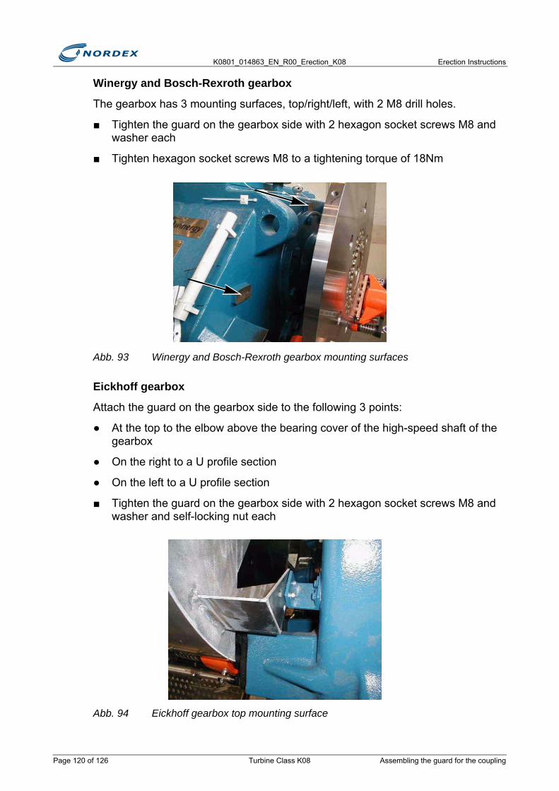
K0801_014863_EN_R00_Erection_K08 Erection Instructions
Winergy and Bosch-Rexroth gearbox
The gearbox has 3 mounting surfaces, top/right/left, with 2 M8 drill holes.
■ Tighten the guard on the gearbox side with 2 hexagon socket screws M8 and washer each
■ Tighten hexagon socket screws M8 to a tightening torque of 18Nm
Abb. 93 Winergy and Bosch-Rexroth gearbox mounting surfaces
Eickhoff gearbox
Attach the guard on the gearbox side to the following 3 points:
● At the top to the elbow above the bearing cover of the high-speed shaft of the gearbox
● On the right to a U profile section
● On the left to a U profile section
■ Tighten the guard on the gearbox side with 2 hexagon socket screws M8 and washer and self-locking nut each
Abb. 94 Eickhoff gearbox top mounting surface
Page 120 of 126 Turbine Class K08 Assembling the guard for the coupling

Erection Instructions K0801_014863_EN_R00_Erection_K08
■ Tighten the 2 parts of the guard on the gearbox side one under the other with 5 hexagon socket screws M8 and washer and self-locking nut each
■ Screw the 2 parts of the guard on the generator side successively to the mounting surfaces on the generator
■ Tighten the guard on the generator side with 10 hexagon socket screws M8 and washer each
■ Tighten hexagon socket screws M8 to a tightening torque of 18Nm
■ Tighten the 2 parts of the guard on the gearbox side one under the other with 6 hexagon socket screws M8 and washer and self-locking nut each
Abb. 95 Guard for coupling
7.10 Commissioning and testing the rotor brakePrior to unlocking the rotor, make sure that the rotor brake functions properly.
Test the rotor brake
■ Move the lever of valve no. 610 on the hydraulic unit towards the manometer (in the figure to the right).
Commissioning and testing the rotor brake Turbine Class K08 Page 121 of 126

K0801_014863_EN_R00_Erection_K08 Erection Instructions
Abb. 96 Hydraulic unit
1. Hand pump2. Valve 810.2 (behind the round component)3. Valve
640, roof, lever spring-centered4. Valve 610, lever engages in 3 positions5. Valve
600, rotor lock, lever is spring-centered
■ Remove the extension pipe from the bracket
■ Attach the extension pipe to the lever of the hand pump
■ Build up a pressure of 115bar by using the hand pump
? The rotor brake is applied
Release the rotor brake
■ Open valve 820.2
■ Close valve 810.2
Locking the rotor
The rotor lock bolt at the rotor shaft (low-speed shaft) must be inserted when working on the following components:
● Rotor
● Rotor brake
● Rotor hub
● Gearbox
43 521
Page 122 of 126 Turbine Class K08 Commissioning and testing the rotor brake
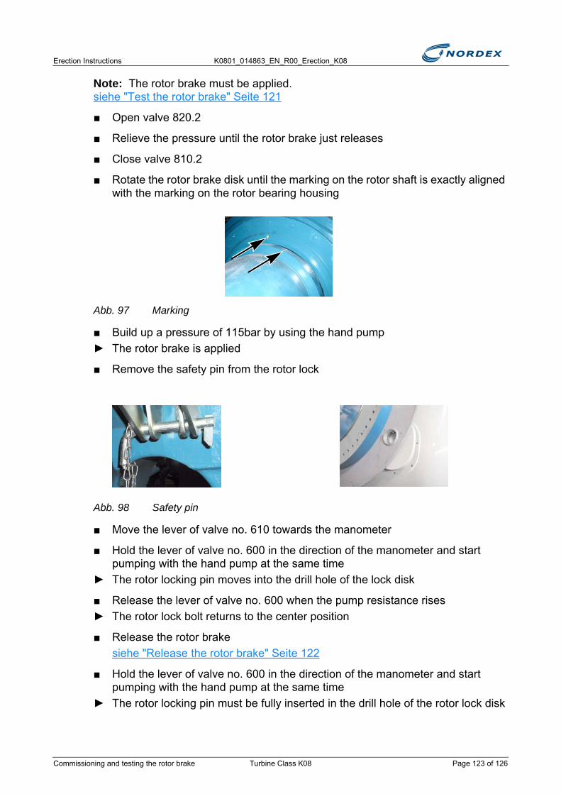
Erection Instructions K0801_014863_EN_R00_Erection_K08
Note: The rotor brake must be applied. siehe "Test the rotor brake" Seite 121
■ Open valve 820.2
■ Relieve the pressure until the rotor brake just releases
■ Close valve 810.2
■ Rotate the rotor brake disk until the marking on the rotor shaft is exactly aligned with the marking on the rotor bearing housing
Abb. 97 Marking
■ Build up a pressure of 115bar by using the hand pump► The rotor brake is applied
■ Remove the safety pin from the rotor lock
Abb. 98 Safety pin
■ Move the lever of valve no. 610 towards the manometer
■ Hold the lever of valve no. 600 in the direction of the manometer and start pumping with the hand pump at the same time
► The rotor locking pin moves into the drill hole of the lock disk
■ Release the lever of valve no. 600 when the pump resistance rises► The rotor lock bolt returns to the center position
■ Release the rotor brakesiehe "Release the rotor brake" Seite 122
■ Hold the lever of valve no. 600 in the direction of the manometer and start pumping with the hand pump at the same time
► The rotor locking pin must be fully inserted in the drill hole of the rotor lock disk
Commissioning and testing the rotor brake Turbine Class K08 Page 123 of 126
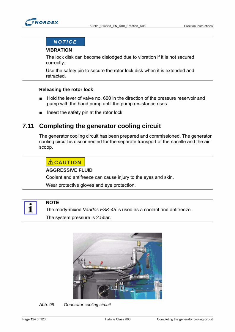
K0801_014863_EN_R00_Erection_K08 Erection Instructions
Releasing the rotor lock
■ Hold the lever of valve no. 600 in the direction of the pressure reservoir and pump with the hand pump until the pump resistance rises
■ Insert the safety pin at the rotor lock
7.11 Completing the generator cooling circuitThe generator cooling circuit has been prepared and commissioned. The generator cooling circuit is disconnected for the separate transport of the nacelle and the air scoop.
Abb. 99 Generator cooling circuit
VIBRATIONThe lock disk can become dislodged due to vibration if it is not secured correctly.
Use the safety pin to secure the rotor lock disk when it is extended and retracted.
AGGRESSIVE FLUIDCoolant and antifreeze can cause injury to the eyes and skin.
Wear protective gloves and eye protection.
NOTEThe ready-mixed Varidos FSK-45 is used as a coolant and antifreeze.
The system pressure is 2.5bar.
N O T I C E
CAUTION
Page 124 of 126 Turbine Class K08 Completing the generator cooling circuit

Erection Instructions K0801_014863_EN_R00_Erection_K08
■ Fit the connections
■ Open the ball valves
Check the coolant density
■ Connect the hand pump to the drain cock
■ Take a sample
■ Heat the sample to 20°C
■ Measure the coolant density with a antifreeze tester (siehe Abb.100)
Abb. 100 antifreeze tester
1. 1.062 g/cm3
■ Thoroughly vent the cooling system
NOTE
Density at 20°C approx. 1.062g/cm3, approx. 45Vol.-%
If the density is outside the tolerance limits of 1.056 to 1.067g/cm3 (40–50Vol.-%), the complete coolant must be replaced.
1
Completing the generator cooling circuit Turbine Class K08 Page 125 of 126
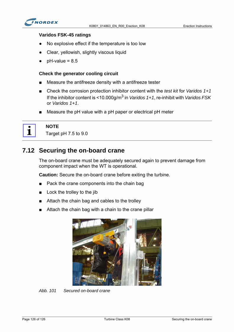
K0801_014863_EN_R00_Erection_K08 Erection Instructions
Varidos FSK-45 ratings
● No explosive effect if the temperature is too low
● Clear, yellowish, slightly viscous liquid
● pH-value = 8.5
Check the generator cooling circuit
■ Measure the antifreeze density with a antifreeze tester
■ Check the corrosion protection inhibitor content with the test kit for Varidos 1+1If the inhibitor content is <10.000g/m3 in Varidos 1+1, re-inhibit with Varidos FSK or Varidos 1+1.
■ Measure the pH value with a pH paper or electrical pH meter
7.12 Securing the on-board craneThe on-board crane must be adequately secured again to prevent damage from component impact when the WT is operational.
Caution: Secure the on-board crane before exiting the turbine.
■ Pack the crane components into the chain bag
■ Lock the trolley to the jib
■ Attach the chain bag and cables to the trolley
■ Attach the chain bag with a chain to the crane pillar
Abb. 101 Secured on-board crane
NOTETarget pH 7.5 to 9.0
Page 126 of 126 Turbine Class K08 Securing the on-board crane
Erection Instructions K0801_014863_EN_R00_Erection_K08
8. Rotor erectionTo erect the rotor the following work must be carried out:
Preparatory work
● Unloading and preassembling the rotor hub- Position the rotor hub- Prepare the pitch bearing- Assemble the hub cage
Assemble the rotor hub and rotor blade
● Star assembly- Attach the rotor blades- Prepare and install the rotor blades (on the ground)- Lift and assemble the star
● Single blade assembly- Assemble the rotor hub- Assemble the geared motor- Install the rotor blades
Completion
● Final work- Lock the rotor- Move the rotor blades into the feathering position- Turn the nacelle into wind- Remove the geared motor and lift it out of the nacelle
8.1 Unloading and preassembling the rotor hub■ Attach rotor hub to the 6 fitted lifting tackle
■ Unload rotor hub
Unloading and preassembling the rotor hub Turbine Class K08 Page 127 of 152
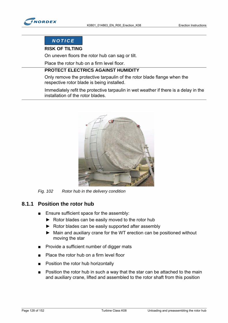
K0801_014863_EN_R00_Erection_K08 Erection Instructions
Fig. 102 Rotor hub in the delivery condition
8.1.1 Position the rotor hub■ Ensure sufficient space for the assembly:
► Rotor blades can be easily moved to the rotor hub► Rotor blades can be easily supported after assembly► Main and auxiliary crane for the WT erection can be positioned without
moving the star
■ Provide a sufficient number of digger mats
■ Place the rotor hub on a firm level floor
■ Position the rotor hub horizontally
■ Position the rotor hub in such a way that the star can be attached to the main and auxiliary crane, lifted and assembled to the rotor shaft from this position
RISK OF TILTINGOn uneven floors the rotor hub can sag or tilt.
Place the rotor hub on a firm level floor.PROTECT ELECTRICS AGAINST HUMIDITYOnly remove the protective tarpaulin of the rotor blade flange when the respective rotor blade is being installed.
Immediately refit the protective tarpaulin in wet weather if there is a delay in the installation of the rotor blades.
N O T I C E
Page 128 of 152 Turbine Class K08 Unloading and preassembling the rotor hub

Erection Instructions K0801_014863_EN_R00_Erection_K08
■ Protect electrics against humidity:► Only remove the protective tarpaulin of a rotor blade flange when the rotor
blade is being installed► Refit the protective tarpaulin if wet weather delays the installation of the rotor
blades
8.1.2 Prepare the pitch bearing■ Remove 6 lifting tackle from the pitch bearing
■ Make M36 studs from the box of screws available in the nacelleNote: Screw the M36 studs into the tap holes of the lifting tackle
■ Lightly lubricate the studs on both sides
■ Screw in the M36 studs► The identifying marks on the studs must be visible, see Fig.103► Screw protrusion: 77+2mm, see Fig.104
Fig. 103 Stud identifying mark
Fig. 104 Tighten the studs of the pitch bearing
Unloading and preassembling the rotor hub Turbine Class K08 Page 129 of 152
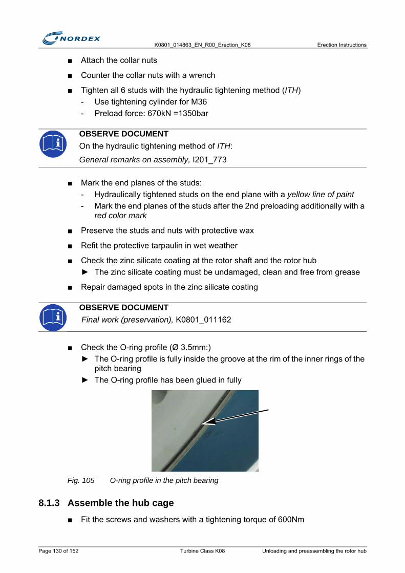
K0801_014863_EN_R00_Erection_K08 Erection Instructions
■ Attach the collar nuts
■ Counter the collar nuts with a wrench
■ Tighten all 6 studs with the hydraulic tightening method (ITH)- Use tightening cylinder for M36- Preload force: 670kN =1350bar
■ Mark the end planes of the studs:- Hydraulically tightened studs on the end plane with a yellow line of paint- Mark the end planes of the studs after the 2nd preloading additionally with a
red color mark
■ Preserve the studs and nuts with protective wax
■ Refit the protective tarpaulin in wet weather
■ Check the zinc silicate coating at the rotor shaft and the rotor hub► The zinc silicate coating must be undamaged, clean and free from grease
■ Repair damaged spots in the zinc silicate coating
■ Check the O-ring profile (Ø 3.5mm:)► The O-ring profile is fully inside the groove at the rim of the inner rings of the
pitch bearing► The O-ring profile has been glued in fully
Fig. 105 O-ring profile in the pitch bearing
8.1.3 Assemble the hub cage■ Fit the screws and washers with a tightening torque of 600Nm
OBSERVE DOCUMENTOn the hydraulic tightening method of ITH:
General remarks on assembly, I201_773
OBSERVE DOCUMENT Final work (preservation), K0801_011162
Page 130 of 152 Turbine Class K08 Unloading and preassembling the rotor hub
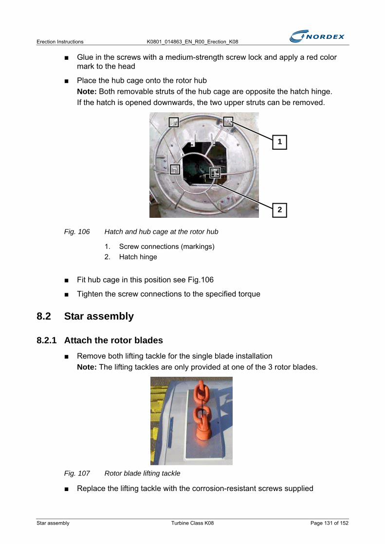
Erection Instructions K0801_014863_EN_R00_Erection_K08
■ Glue in the screws with a medium-strength screw lock and apply a red color mark to the head
■ Place the hub cage onto the rotor hubNote: Both removable struts of the hub cage are opposite the hatch hinge.If the hatch is opened downwards, the two upper struts can be removed.
Fig. 106 Hatch and hub cage at the rotor hub
1. Screw connections (markings)2. Hatch hinge
■ Fit hub cage in this position see Fig.106
■ Tighten the screw connections to the specified torque
8.2 Star assembly
8.2.1 Attach the rotor blades■ Remove both lifting tackle for the single blade installation
Note: The lifting tackles are only provided at one of the 3 rotor blades.
Fig. 107 Rotor blade lifting tackle
■ Replace the lifting tackle with the corrosion-resistant screws supplied
2
1
Star assembly Turbine Class K08 Page 131 of 152
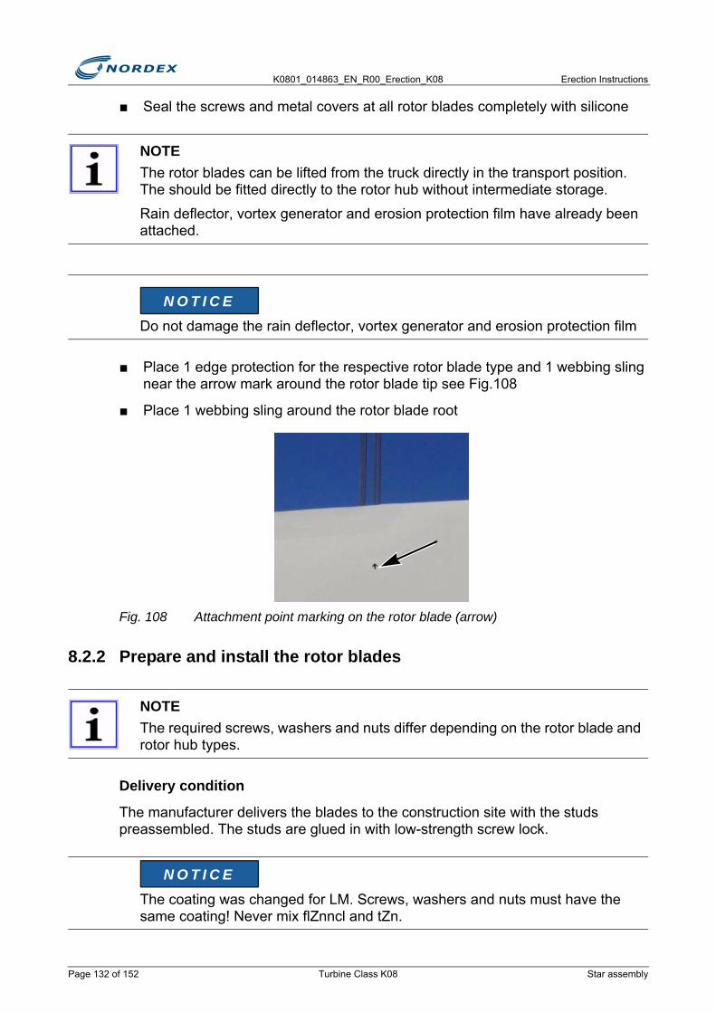
K0801_014863_EN_R00_Erection_K08 Erection Instructions
■ Seal the screws and metal covers at all rotor blades completely with silicone
■ Place 1 edge protection for the respective rotor blade type and 1 webbing sling near the arrow mark around the rotor blade tip see Fig.108
■ Place 1 webbing sling around the rotor blade root
Fig. 108 Attachment point marking on the rotor blade (arrow)
8.2.2 Prepare and install the rotor blades
Delivery condition
The manufacturer delivers the blades to the construction site with the studs preassembled. The studs are glued in with low-strength screw lock.
NOTEThe rotor blades can be lifted from the truck directly in the transport position. The should be fitted directly to the rotor hub without intermediate storage.
Rain deflector, vortex generator and erosion protection film have already been attached.
Do not damage the rain deflector, vortex generator and erosion protection film
NOTEThe required screws, washers and nuts differ depending on the rotor blade and rotor hub types.
The coating was changed for LM. Screws, washers and nuts must have the same coating! Never mix flZnncl and tZn.
N O T I C E
N O T I C E
Page 132 of 152 Turbine Class K08 Star assembly
Erection Instructions K0801_014863_EN_R00_Erection_K08
Screw connection per rotor blade to rotor hub (rotor blade types NR 45, LM 38.8 and LM 43.8)
■ Preload the screw connections crosswise with 4 nuts at a time- Preload torque NR: 1700Nm- Preload torque LM: 2000NmCaution: Do not exceed the preloads!
■ Tighten the screw connections crosswise with 4 nuts at a time until all screw connections have the correct torque
Screw connection per rotor blade to rotor hub (LM 48.8 with standard rotor hub)
DAMAGED THREADSThe screw threads must be clean, dry, and free from grease and oil.
Clean studs with a degreasing agent if grease or oil are present on the threads.
SAFETY-RELEVANT SCREWSEnter the following information in the erection report to enable the screw connection to be identified uniquely:
• Nominal diameter• Length• Manufacturer• Grade/Coating• Serial number/Year
Studs and nuts feature a coating with integrated lubricant (flZnncL).
Do not lubricate the studs and nuts.
Studs and nuts feature a coating with integrated lubricant (tZn).
Do not lubricate the studs and nuts.
N O T I C E
N O T I C E
N O T I C E
N O T I C E
Star assembly Turbine Class K08 Page 133 of 152
K0801_014863_EN_R00_Erection_K08 Erection Instructions
■ Preload the screw connections crosswise with 4 nuts at a time- Preload torque: 1400NmCaution: Do not exceed the preloads.
■ Tighten the screw connections crosswise with 4 nuts at a time until all screw connections have the correct torque- Tightening torque: 2000Nm
Screw connection per rotor blade to rotor hub (types LM 38.8 and LM 43.8, without integrated lubrication)
■ Preload the screw connections crosswise with 4 nuts at a time- Preload torque 2000NmCaution: Do not exceed the preloads.
■ Tighten the screw connections crosswise with 4 nuts at a time until all screw connections have the correct torque- Tightening torque: 2800Nm
■ Check the following items:► The O-ring profile (ø 3.5mm) is properly inside the groove at the rim of the
inner rings of the pitch bearing► The O-ring profile has been glued in properly► End plane of the 0° screw is marked in signal color (red/yellow) at each rotor
blade
Studs and nuts are pretreated (tZn).
Do not lubricate the studs and nuts.
NOTEPosition of the 0° screw:
Left to the 0° marking of the rotor blade (when looking at the rotor blade root towards the blade tip), see Fig.109.
The 0° screw is marked to be easier to detect during assembly and maintenance.
N O T I C E
Page 134 of 152 Turbine Class K08 Star assembly
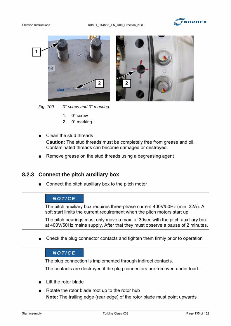
Erection Instructions K0801_014863_EN_R00_Erection_K08
Fig. 109 0° screw and 0° marking
1. 0° screw2. 0° marking
■ Clean the stud threadsCaution: The stud threads must be completely free from grease and oil. Contaminated threads can become damaged or destroyed.
■ Remove grease on the stud threads using a degreasing agent
8.2.3 Connect the pitch auxiliary box■ Connect the pitch auxiliary box to the pitch motor
■ Check the plug connector contacts and tighten them firmly prior to operation
■ Lift the rotor blade
■ Rotate the rotor blade root up to the rotor hubNote: The trailing edge (rear edge) of the rotor blade must point upwards
The pitch auxiliary box requires three-phase current 400V/50Hz (min. 32A). A soft start limits the current requirement when the pitch motors start up.
The pitch bearings must only move a max. of 30sec with the pitch auxiliary box at 400V/50Hz mains supply. After that they must observe a pause of 2 minutes.
The plug connection is implemented through indirect contacts.
The contacts are destroyed if the plug connectors are removed under load.
1
2 2
N O T I C E
N O T I C E
Star assembly Turbine Class K08 Page 135 of 152

K0801_014863_EN_R00_Erection_K08 Erection Instructions
■ Rotate the pitch bearing into the assembly position using the pitch auxiliary box:- Align the 0° marking of the rotor hub (marked hole) with the 0° screw of the
rotor blade
■ Rotate the pitch bearing accordingly using the pitch auxiliary box- Every rotor blade must be screwed to the pitch bearing in the rotor hub- Screw the 0° screw into the marked hole of the pitch bearing
■ Carefully move the rotor blade along with the crane and / or rotate the pitch bearing slightly to and fro if problems are encountered when inserting the rotor blade screws
■ Screw 1 ISO washer and 1 hexagonal nut manually onto each stud up to the pitch bearing
■ Tighten the screw connections crosswise in groups of 4 nuts at a time using an impact wrench
■ Tighten the remaining nuts using an impact wrench
■ Detach the crane from the rotor blade root
■ Rotate the rotor blade such that all screw connections can be tightened crosswise in groups of 4 to the specified preload torqueNote: The tightening torque can be applied either now on the floor or later after fitting the star to the rotor shaft.
8.2.4 Move the rotor blade into the 90° position (feathering position)■ Connect the pitch auxiliary box to the next pitch drive
NOISENoise can cause hearing damage.
Always wear ear protection when working with an impact wrench.
NOTENot all nuts are accessible by the impact wrench.
Use a wrench in addition
DO NOT MOVE THE PITCH BEARING BEYOND 360°The gear cam limit switch system loses its preset state if the pitch bearing is moved beyond 360°.
Move the pitch bearing max. 340°. Then move back to the original position.
CAUTION
N O T I C E
Page 136 of 152 Turbine Class K08 Star assembly

Erection Instructions K0801_014863_EN_R00_Erection_K08
■ Place the rotor blade onto the rotor blade bearing block see Fig.110Note: The position of the bearing block is marked on the rotor blade by a small black arrow.
■ Detach the crane
Fig. 110 Bearing block for rotor blade
Fig. 111 Rotor hub, 1 rotor blade fitted
8.2.5 Install rotor blades 2 and 3■ Fit the 2nd and 3rd rotor blade as rotor blade 1
■ After fitting the 3rd rotor blade remove both bearing blocks
The rotor hub with the rotor blade must also stand firmly in strong gusts of wind.
Brace the rotor blade with ground anchors and ratchet straps
N O T I C E
Star assembly Turbine Class K08 Page 137 of 152

K0801_014863_EN_R00_Erection_K08 Erection Instructions
8.2.6 Install the star
Preparatory work
■ Check the prerequisites► The drive train is completely bolted to the nacelle
■ Turn the rotor shaft so that is in the Y position► The rotor shaft is in the Y position
Fig. 112 Rotor in Y position
1. Torque support for the slip ring2. Hole for rotor lock
NOTEThe rotor shaft must be in the following position:
The torque support for the slip ring points towards the converter cabinet (FU1) of the rotor blade flange 1, see Fig.112.
NOTEThe torque support is also used as a cable duct to the converter cabinet 1.
Rotate the torque support by 120° at a time if it points into a different direction. The required M16 tap holes are provided in the rotor shaft.
To the star with the guide ropes sufficient personnel or machines (construction vehicles, tractors) must be available.
2
1
Page 138 of 152 Turbine Class K08 Star assembly

Erection Instructions K0801_014863_EN_R00_Erection_K08
Alignment rotor lock disk - rotor: Insert the guide pin on the rotor shaft flange into 1 of the 3 equally spaced holes in the rotor hub, see Fig. 119
Fit the lifting tackle for the rotor hub and the rotor blades
Fig. 113 Lifting tackles for the star
Fig. 114 Screw holes for the lifting tackle
1. Screws 2–6 (2x)2. Screw 1
NOTEThe screws 2–6 have normally been removed to allow the two lifting tackles for the star to be fitted to the rotor bearing.
The removed screws are in the rotor hub. They are attached to the pitch box frame.
2
1
Star assembly Turbine Class K08 Page 139 of 152
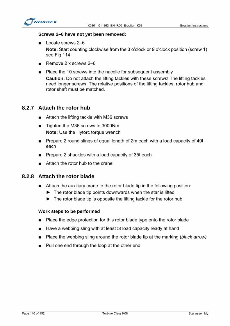
K0801_014863_EN_R00_Erection_K08 Erection Instructions
Screws 2–6 have not yet been removed:
■ Locate screws 2–6Note: Start counting clockwise from the 3 o’clock or 9 o’clock position (screw 1) see Fig.114
■ Remove 2 x screws 2–6
■ Place the 10 screws into the nacelle for subsequent assemblyCaution: Do not attach the lifting tackles with these screws! The lifting tackles need longer screws. The relative positions of the lifting tackles, rotor hub and rotor shaft must be matched.
8.2.7 Attach the rotor hub■ Attach the lifting tackle with M36 screws
■ Tighten the M36 screws to 3000NmNote: Use the Hytorc torque wrench
■ Prepare 2 round slings of equal length of 2m each with a load capacity of 40t each
■ Prepare 2 shackles with a load capacity of 35t each
■ Attach the rotor hub to the crane
8.2.8 Attach the rotor blade■ Attach the auxiliary crane to the rotor blade tip in the following position:
► The rotor blade tip points downwards when the star is lifted► The rotor blade tip is opposite the lifting tackle for the rotor hub
Work steps to be performed
■ Place the edge protection for this rotor blade type onto the rotor blade
■ Have a webbing sling with at least 5t load capacity ready at hand
■ Place the webbing sling around the rotor blade tip at the marking (black arrow)
■ Pull one end through the loop at the other end
Page 140 of 152 Turbine Class K08 Star assembly
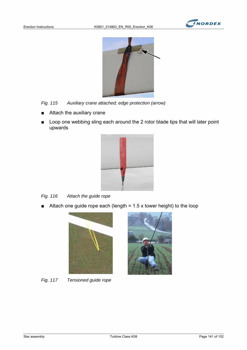
Erection Instructions K0801_014863_EN_R00_Erection_K08
Fig. 115 Auxiliary crane attached; edge protection (arrow)
■ Attach the auxiliary crane
■ Loop one webbing sling each around the 2 rotor blade tips that will later point upwards
Fig. 116 Attach the guide rope
■ Attach one guide rope each (length = 1.5 x tower height) to the loop
Fig. 117 Tensioned guide rope
Star assembly Turbine Class K08 Page 141 of 152
K0801_014863_EN_R00_Erection_K08 Erection Instructions
8.2.9 Lift and assemble the star
■ Check the rotor hub► The rotor hub must be clean and free from loose materials and tools
■ Undo the fastening screws between the rotor hub and the transport frameThe main and auxiliary crane slowly take up the load
■ Monitor the rotor- The rotor must not knock against anything- The rotor must reach a height of approx. 2m
■ Stop the rotor at a height of approx. 2m
■ Check the zinc silicate coating of the shaft flange
■ Repair damaged spots in the zinc silicate coating
■ Screw the guide pin into the hole in the rotor hub flange next to the hole for the centering pin
Lift the star
■ Always keep the guide ropes tensioned- The auxiliary crane must flow slowly until the rotor is suspended vertically
.
■ Detach the auxiliary crane once it is without load
NOTE• Observe the rotor movements• Control via radio:
- the work of the crane operator - the work of the support team on the guide ropes
• Coordinate the installers in the nacelle• Define unique communication signals between the site manager, crane
operator and safety person
OBSERVE DOCUMENTFinal work (preservation), K0801_011162
Keep the sling as vertical to the rotor blade and tight as possible. The loop can slip away if the rotor reaches the vertical position.
N O T I C E
Page 142 of 152 Turbine Class K08 Star assembly
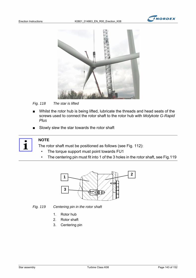
Erection Instructions K0801_014863_EN_R00_Erection_K08
Fig. 118 The star is lifted
■ Whilst the rotor hub is being lifted, lubricate the threads and head seats of the screws used to connect the rotor shaft to the rotor hub with Molykote G-Rapid Plus
■ Slowly slew the star towards the rotor shaft
Fig. 119 Centering pin in the rotor shaft
1. Rotor hub2. Rotor shaft3. Centering pin
NOTEThe rotor shaft must be positioned as follows (see Fig. 112):
• The torque support must point towards FU1• The centering pin must fit into 1 of the 3 holes in the rotor shaft, see Fig.119
21
3
Star assembly Turbine Class K08 Page 143 of 152
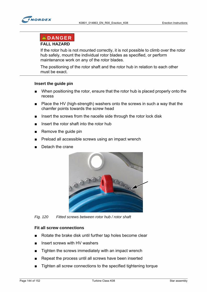
K0801_014863_EN_R00_Erection_K08 Erection Instructions
Insert the guide pin
■ When positioning the rotor, ensure that the rotor hub is placed properly onto the recess
■ Place the HV (high-strength) washers onto the screws in such a way that the chamfer points towards the screw head
■ Insert the screws from the nacelle side through the rotor lock disk
■ Insert the rotor shaft into the rotor hub
■ Remove the guide pin
■ Preload all accessible screws using an impact wrench
■ Detach the crane
Fig. 120 Fitted screws between rotor hub / rotor shaft
Fit all screw connections
■ Rotate the brake disk until further tap holes become clear
■ Insert screws with HV washers
■ Tighten the screws immediately with an impact wrench
■ Repeat the process until all screws have been inserted
■ Tighten all screw connections to the specified tightening torque
FALL HAZARDIf the rotor hub is not mounted correctly, it is not possible to climb over the rotor hub safely, mount the individual rotor blades as specified, or perform maintenance work on any of the rotor blades.
The positioning of the rotor shaft and the rotor hub in relation to each other must be exact.
DANGER
Page 144 of 152 Turbine Class K08 Star assembly
Erection Instructions K0801_014863_EN_R00_Erection_K08
Screw connection rotor hub – rotor shaft
■ Lubricate the threads and head seats of the screws with Molykote G-Rapid Plus
■ Replace the lifting tackle at the rotor hub
■ Loosen the screws of the lifting tackles at the pitch bearing
■ Leave the screws in the lifting tackle.
■ Pull out the lifting tackle with the crane in such a way that not screws can fall down
■ Protect the tightening cylinder from falling
■ Attach 1 secured rope to the eyebolt
■ Prepare the removed screws 12–16Note: M36 studs are attached to the frame of the pitch box in the rotor hub and are screwed into the tap holes of the lifting tackles.
■ Lightly oil the studs on both sides
■ Screw in the M36 studs- The identifying mark on the screws must be visible
Screw protrusion: 77 + 2mm
Designation Wrench size QuantityHexagon screw: M36 x 290- 10.9- tZn 55mm 60
Washer: HV – 37 C 45 – tZn
Tightening torques: Preload torque: 1000Nm
Tightening torque: 8000Nm
SAFETY-RELEVANT SCREWSEnter the following information in the erection report to enable the screw connection to be identified uniquely:
• Nominal diameter• Length• Manufacturer• Grade/Coating• Serial number/Year
N O T I C E
Star assembly Turbine Class K08 Page 145 of 152

K0801_014863_EN_R00_Erection_K08 Erection Instructions
Fig. 121 Tighten the studs of the pitch bearing
■ Attach the collar nuts
■ Tighten all screws with the hydraulic tightening method (ITH)- Tightening cylinder for M36- Required preload force 670kN / 1350bar
■ Mark the end planes of the tightened stud bolts with a yellow paint line
■ Insert the rotor lock at the rotor shaft
■ Mark the end planes of the studs after the 2nd preloading additionally with a red mark
■ Preserve the studs and nuts with protective wax
■ Turn the rotor blades to feathered position (by 180°)
OBSERVE DOCUMENTGeneral remarks on assembly, I201_773
Page 146 of 152 Turbine Class K08 Star assembly
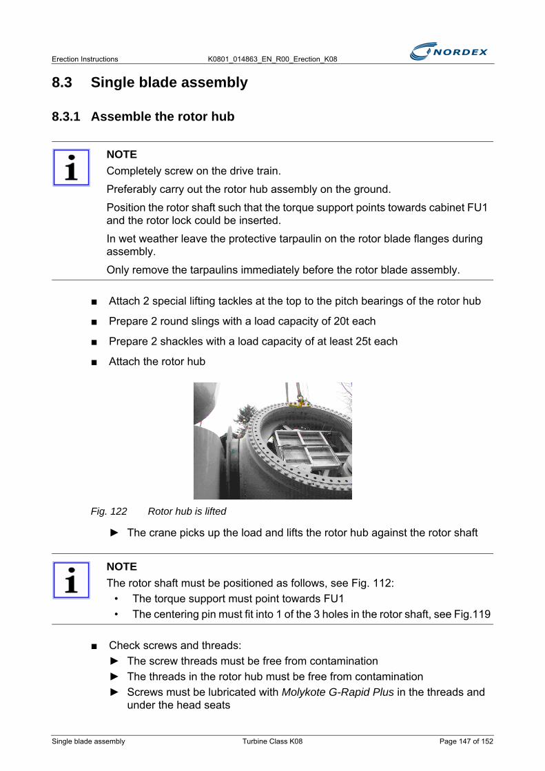
Erection Instructions K0801_014863_EN_R00_Erection_K08
8.3 Single blade assembly
8.3.1 Assemble the rotor hub
■ Attach 2 special lifting tackles at the top to the pitch bearings of the rotor hub
■ Prepare 2 round slings with a load capacity of 20t each
■ Prepare 2 shackles with a load capacity of at least 25t each
■ Attach the rotor hub
Fig. 122 Rotor hub is lifted
► The crane picks up the load and lifts the rotor hub against the rotor shaft
■ Check screws and threads:► The screw threads must be free from contamination► The threads in the rotor hub must be free from contamination► Screws must be lubricated with Molykote G-Rapid Plus in the threads and
under the head seats
NOTECompletely screw on the drive train.
Preferably carry out the rotor hub assembly on the ground.
Position the rotor shaft such that the torque support points towards cabinet FU1 and the rotor lock could be inserted.
In wet weather leave the protective tarpaulin on the rotor blade flanges during assembly.
Only remove the tarpaulins immediately before the rotor blade assembly.
NOTEThe rotor shaft must be positioned as follows, see Fig. 112:
• The torque support must point towards FU1• The centering pin must fit into 1 of the 3 holes in the rotor shaft, see Fig.119
Single blade assembly Turbine Class K08 Page 147 of 152
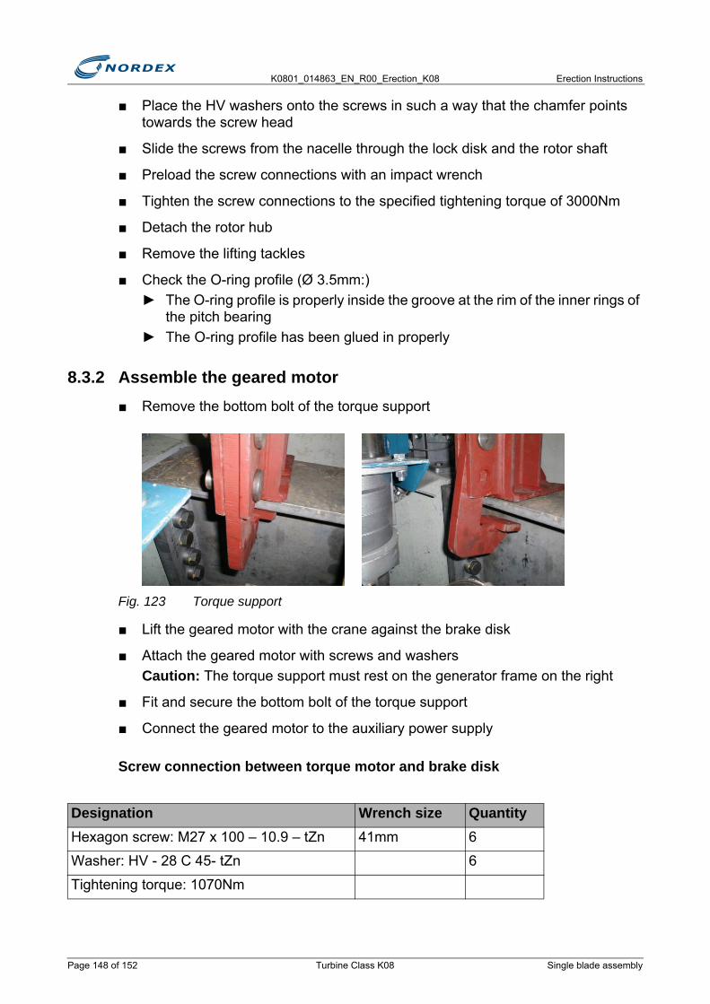
K0801_014863_EN_R00_Erection_K08 Erection Instructions
■ Place the HV washers onto the screws in such a way that the chamfer points towards the screw head
■ Slide the screws from the nacelle through the lock disk and the rotor shaft
■ Preload the screw connections with an impact wrench
■ Tighten the screw connections to the specified tightening torque of 3000Nm
■ Detach the rotor hub
■ Remove the lifting tackles
■ Check the O-ring profile (Ø 3.5mm:)► The O-ring profile is properly inside the groove at the rim of the inner rings of
the pitch bearing► The O-ring profile has been glued in properly
8.3.2 Assemble the geared motor■ Remove the bottom bolt of the torque support
Fig. 123 Torque support
■ Lift the geared motor with the crane against the brake disk
■ Attach the geared motor with screws and washersCaution: The torque support must rest on the generator frame on the right
■ Fit and secure the bottom bolt of the torque support
■ Connect the geared motor to the auxiliary power supply
Screw connection between torque motor and brake disk
Designation Wrench size QuantityHexagon screw: M27 x 100 – 10.9 – tZn 41mm 6
Washer: HV - 28 C 45- tZn 6
Tightening torque: 1070Nm
Page 148 of 152 Turbine Class K08 Single blade assembly
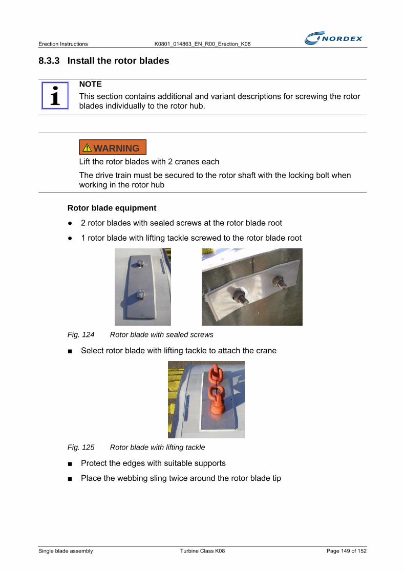
Erection Instructions K0801_014863_EN_R00_Erection_K08
8.3.3 Install the rotor blades
Rotor blade equipment
● 2 rotor blades with sealed screws at the rotor blade root
● 1 rotor blade with lifting tackle screwed to the rotor blade root
Fig. 124 Rotor blade with sealed screws
■ Select rotor blade with lifting tackle to attach the crane
Fig. 125 Rotor blade with lifting tackle
■ Protect the edges with suitable supports
■ Place the webbing sling twice around the rotor blade tip
NOTEThis section contains additional and variant descriptions for screwing the rotor blades individually to the rotor hub.
Lift the rotor blades with 2 cranes each
The drive train must be secured to the rotor shaft with the locking bolt when working in the rotor hub
WARNING
Single blade assembly Turbine Class K08 Page 149 of 152
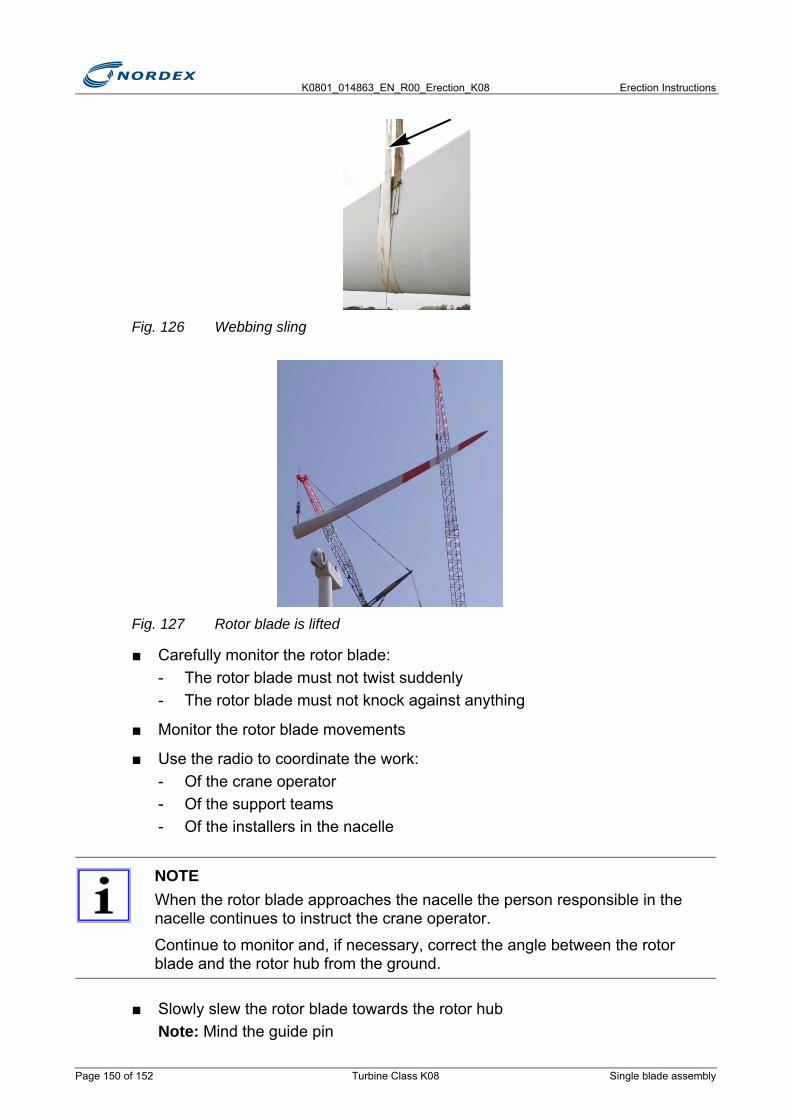
K0801_014863_EN_R00_Erection_K08 Erection Instructions
Fig. 126 Webbing sling
Fig. 127 Rotor blade is lifted
■ Carefully monitor the rotor blade:- The rotor blade must not twist suddenly- The rotor blade must not knock against anything
■ Monitor the rotor blade movements
■ Use the radio to coordinate the work:- Of the crane operator- Of the support teams - Of the installers in the nacelle
■ Slowly slew the rotor blade towards the rotor hubNote: Mind the guide pin
NOTEWhen the rotor blade approaches the nacelle the person responsible in the nacelle continues to instruct the crane operator.
Continue to monitor and, if necessary, correct the angle between the rotor blade and the rotor hub from the ground.
Page 150 of 152 Turbine Class K08 Single blade assembly
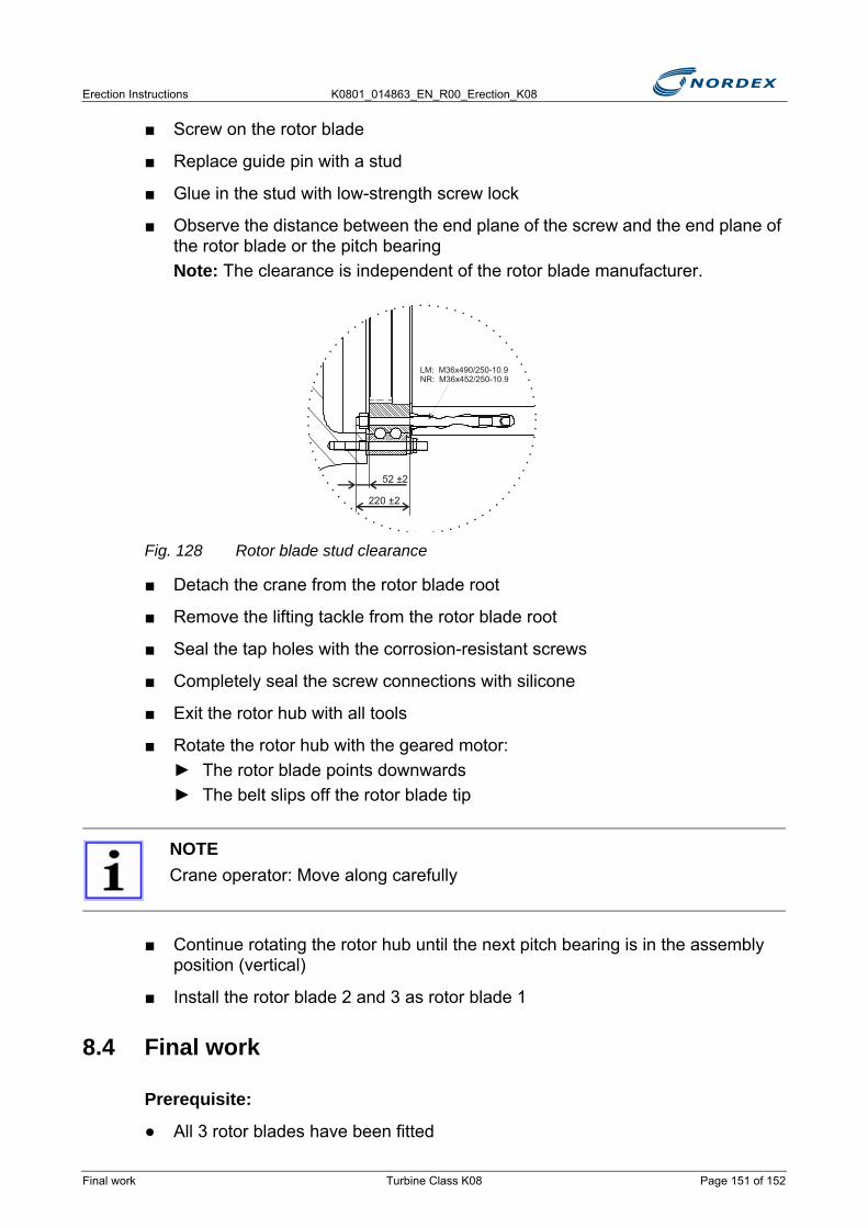
Erection Instructions K0801_014863_EN_R00_Erection_K08
■ Screw on the rotor blade
■ Replace guide pin with a stud
■ Glue in the stud with low-strength screw lock
■ Observe the distance between the end plane of the screw and the end plane of the rotor blade or the pitch bearingNote: The clearance is independent of the rotor blade manufacturer.
Fig. 128 Rotor blade stud clearance
■ Detach the crane from the rotor blade root
■ Remove the lifting tackle from the rotor blade root
■ Seal the tap holes with the corrosion-resistant screws
■ Completely seal the screw connections with silicone
■ Exit the rotor hub with all tools
■ Rotate the rotor hub with the geared motor:► The rotor blade points downwards► The belt slips off the rotor blade tip
■ Continue rotating the rotor hub until the next pitch bearing is in the assembly position (vertical)
■ Install the rotor blade 2 and 3 as rotor blade 1
8.4 Final work
Prerequisite:
● All 3 rotor blades have been fitted
NOTECrane operator: Move along carefully
52 ±2
220 ±2
LM: M36x490/250-10.9NR: M36x452/250-10.9
Final work Turbine Class K08 Page 151 of 152

K0801_014863_EN_R00_Erection_K08 Erection Instructions
Work steps to be performed
■ Insert the rotor lock at the rotor shaft
■ Move the rotor blades with the pitch auxiliary box successively into the feathering position (for star assembly rotate 180°, for single blade assembly 90°)► The trailing edge of the rotor blade points towards the nacelle
■ Turn nacelle into wind
■ Remove the geared motor
■ Lift the geared motor out of the nacelle
Page 152 of 152 Turbine Class K08 Final work
Erection Instructions K0801_014863_EN_R00_Erection_K08
9. Electrical installationFor the electrical installation the following tasks must be carried out:
● Connecting the cables in the rotor hub
● Installing power and ground cables
● Ground cables
● Line-side cable connection in the bottom box
● Installing the control cables
● Final cable work
9.1 Notes
Circuit diagrams
The circuit diagrams of the WT are stored in the top box or bottom box.
Labeling
■ Label power cables and control cables in accordance with the cable list and the circuit diagramNote: Labels must be attached to each cable end; approx. 50cm before the gland or the cable inlet.The labeling material is in the bottom box, panel 1
Power and ground cables
■ Only fit cable lugs in accordance with DIN 46235 or compression joints in accordance with DIN 46267 to power and ground cables
■ For crimping only use the appropriate tool inserts in accordance with DIN 46267
Compressed cables
If compressed cables are used (e.g. NYY >50mm2), special sleeves must be used. These sleeves are moved over the compressed cable and then crimped together in the cable lug or compression joint.
This sleeve ensures an adequate filling volume in the cable lug.
ELECTRICITYElectric shock due to incorrect handling of electrics.
The electrical installation must be carried out by electrical professionals only.
DANGER
Notes Turbine Class K08 Page 153 of 170
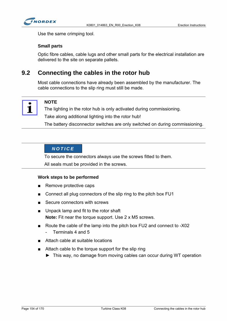
K0801_014863_EN_R00_Erection_K08 Erection Instructions
Use the same crimping tool.
Small parts
Optic fibre cables, cable lugs and other small parts for the electrical installation are delivered to the site on separate pallets.
9.2 Connecting the cables in the rotor hubMost cable connections have already been assembled by the manufacturer. The cable connections to the slip ring must still be made.
Work steps to be performed
■ Remove protective caps
■ Connect all plug connectors of the slip ring to the pitch box FU1
■ Secure connectors with screws
■ Unpack lamp and fit to the rotor shaftNote: Fit near the torque support. Use 2 x M5 screws.
■ Route the cable of the lamp into the pitch box FU2 and connect to -X02- Terminals 4 and 5
■ Attach cable at suitable locations
■ Attach cable to the torque support for the slip ring► This way, no damage from moving cables can occur during WT operation
NOTEThe lighting in the rotor hub is only activated during commissioning.
Take along additional lighting into the rotor hub!
The battery disconnector switches are only switched on during commissioning.
To secure the connectors always use the screws fitted to them.
All seals must be provided in the screws.
N O T I C E
Page 154 of 170 Turbine Class K08 Connecting the cables in the rotor hub

Erection Instructions K0801_014863_EN_R00_Erection_K08
9.3 Installing power and ground cables
9.3.1 Power cable layout■ Arrange power cables in bundles of 3 (1 each of L1, L2, L3 cables)
■ Always route power cables in a delta layoutCaution: Every cable bundle must contain 1 cable L1, L2 and L3 (siehe Abb.129)
Abb. 129 Cable bundle
9.3.2 Routing the power cables■ Route cable bundles in the cableways or in the cable brackets provided
■ Attach cables to the cableways/brackets with large cable ties
NOTELattice towersThe erection of the lattice towers is carried out exclusively by SeeBA Energiesysteme GmbH. This company is also responsible for routing all the cables in the tower and preparing the loop.
The technician for the WT erection only pick up the cables from the top platform of the lattice tower or the cableway to the transformer station and then carry out all subsequent work.
USE ORIGINAL SCREWSThe PG glands for the bottom box are too large for the cables used in the lattice tower.
Replace the existing rubber seal with the supplied thicker rubber seals to close the clearance.
NOTEFit cable bundles at a distance of approx. 50cm from each other.
Use the whole width of the cableway
N O T I C E
L1
L2
L3
Installing power and ground cables Turbine Class K08 Page 155 of 170

K0801_014863_EN_R00_Erection_K08 Erection Instructions
■ Line potential points of abrasion and edges with protective mats
9.3.3 Routing the power cables in the towerAll cables are pre-installed in every tower segment by the tower manufacturer, and the loop is also completely prepared.
■ Align the loop bushings such that the cables are suspended in the center when they are still untwisted
Delivery condition
The cables to be connected to the nacelle are on the top platform in the tower top. These cables are fitted with cable grips and attached to the round ladder.
At the top end of the bottom tower segments the cables are cut flush with the flange and protrude by approx. 0.5m at the bottom end. The two top cable clips in every tower segment are permanently attached.
The bottom clips are only loosely attached.
■ If the bottom clips are not loosely attached, undo the clips
Work Steps to be performed
■ If the cables are suspended tightly, tighten all nuts to 80Nm► All cables must be tightly fastened► Plastic clips may not sag► All stator cables must run straight from top to bottom, i.e. every cable always
has the same place in the bracket
DO NOT DAMAGE CABLESAvoid pressure and abrasion marks in the cable insulation .
Observe minimum bending radius in accordance with DIN VDE 0298, part 3:
Permanent cable routing:• r = 4d• minimum radius = 120mm
Free movement or cable entries:• r = 5d• minimum radius = 150mm
N O T I C E
Page 156 of 170 Turbine Class K08 Installing power and ground cables
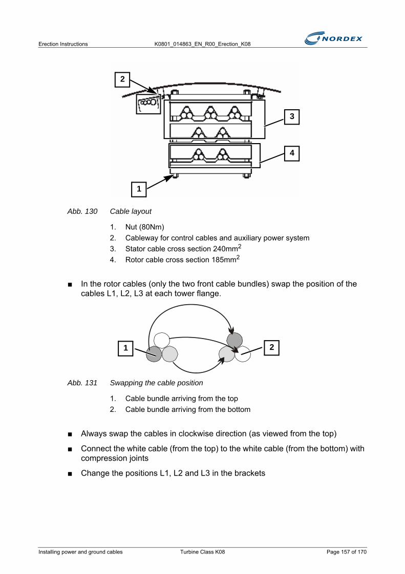
Erection Instructions K0801_014863_EN_R00_Erection_K08
Abb. 130 Cable layout
1. Nut (80Nm)2. Cableway for control cables and auxiliary power system3. Stator cable cross section 240mm2
4. Rotor cable cross section 185mm2
■ In the rotor cables (only the two front cable bundles) swap the position of the cables L1, L2, L3 at each tower flange.
Abb. 131 Swapping the cable position
1. Cable bundle arriving from the top2. Cable bundle arriving from the bottom
■ Always swap the cables in clockwise direction (as viewed from the top)
■ Connect the white cable (from the top) to the white cable (from the bottom) with compression joints
■ Change the positions L1, L2 and L3 in the brackets
1
3
4
2
21
Installing power and ground cables Turbine Class K08 Page 157 of 170
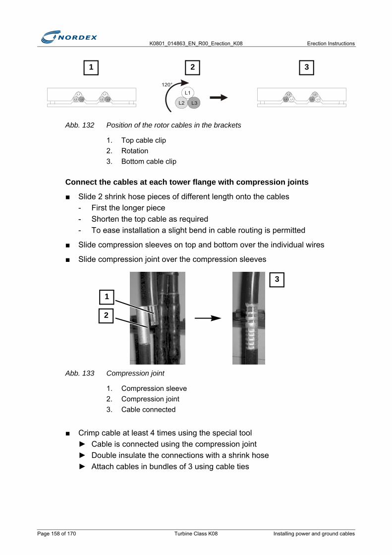
K0801_014863_EN_R00_Erection_K08 Erection Instructions
Abb. 132 Position of the rotor cables in the brackets
1. Top cable clip2. Rotation3. Bottom cable clip
Connect the cables at each tower flange with compression joints
■ Slide 2 shrink hose pieces of different length onto the cables- First the longer piece- Shorten the top cable as required- To ease installation a slight bend in cable routing is permitted
■ Slide compression sleeves on top and bottom over the individual wires
■ Slide compression joint over the compression sleeves
Abb. 133 Compression joint
1. Compression sleeve2. Compression joint3. Cable connected
■ Crimp cable at least 4 times using the special tool► Cable is connected using the compression joint► Double insulate the connections with a shrink hose► Attach cables in bundles of 3 using cable ties
L3
L1
L2
120°
L1L3
L2
L1L3
L2
L3
L1
L2 L3
L1
L2
1 2 3
1
2
3
Page 158 of 170 Turbine Class K08 Installing power and ground cables
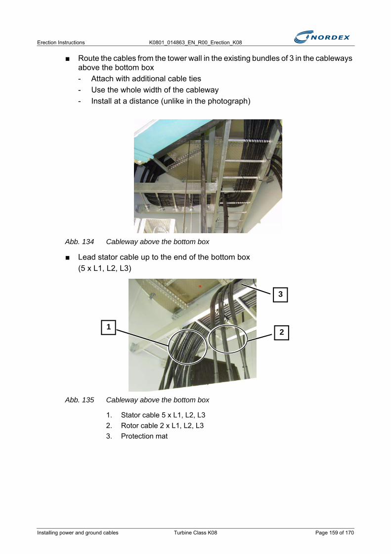
Erection Instructions K0801_014863_EN_R00_Erection_K08
■ Route the cables from the tower wall in the existing bundles of 3 in the cableways above the bottom box- Attach with additional cable ties- Use the whole width of the cableway- Install at a distance (unlike in the photograph)
Abb. 134 Cableway above the bottom box
■ Lead stator cable up to the end of the bottom box(5 x L1, L2, L3)
Abb. 135 Cableway above the bottom box
1. Stator cable 5 x L1, L2, L32. Rotor cable 2 x L1, L2, L33. Protection mat
21
3
Installing power and ground cables Turbine Class K08 Page 159 of 170

K0801_014863_EN_R00_Erection_K08 Erection Instructions
Abb. 136 Cable inlet to the bottom box
■ Route the stator cable from the top through the glands into the bottom box
■ Attach the stator cable to the cableways above the bottom box
■ Route the rotor cable up to the center of the bottom box: 2 x L1, L2, L3
■ Route the rotor cable from the top through the glands into the bottom box
■ Attach the rotor cable to the cableways above the bottom box
Check the conductivity and label the cables individually
Once all cables are connected in the tower they must be checked for conductivity and labelled before being connected to the bottom box.
The supplied labels are in the bottom box. L1, L2, L3 are defined at the bottom of the bottom box.
■ Check the cables individually for conductivity and label them simultaneously at the top (on the top tower platform) and the bottom (at the bottom box)
NOTEThe cables must be connected in different ways depending on the converter manufacturer, see circuit diagram.
IDS
● Stator rotating field, swap the 5 cables (L1-L2) once
● Rotor rotating field, swap the 2 cables (L1-L2) once
SEG
● Stator rotating field, swap the 5 cables (L1-L2) once
● Rotor rotating field, swap the 2 cables (L1-L2) once
Converteam
● Stator rotating field, swap the 5 cables (L1-L2) once
Page 160 of 170 Turbine Class K08 Installing power and ground cables

Erection Instructions K0801_014863_EN_R00_Erection_K08
■ Shorten the cables as required
■ Connect the cables to the terminals in the bottom box- Specified torque: 30Nm- Connect the cables of a bundle each time to 3 terminals arranged on top of
each other. L1 is at the front of the bottom box.
Abb. 137 Cable labeling
1. Stator cable: W01; L1–42. Rotor cable: W02; L3–2
Routing the power cables in the nacelle
■ Undo the shackles of the cable grips from the round ladder
■ Attach the shackles approx. 0.5m higher at the machine frame
NOTEStator cable: W01
Rotor cable: W02
LABEL THE CABLESTo be able to correctly route the cables in bundles of 3 they must first be labelled. If the cables in the tower are only connected later, the cables in the top tower segment can already be checked for conductivity and labelled by hand.
However, this does not replace the check for conductivity prior to connection in the control cabinet
L3L2L1
L3L2L1
21
N O T I C E
Installing power and ground cables Turbine Class K08 Page 161 of 170
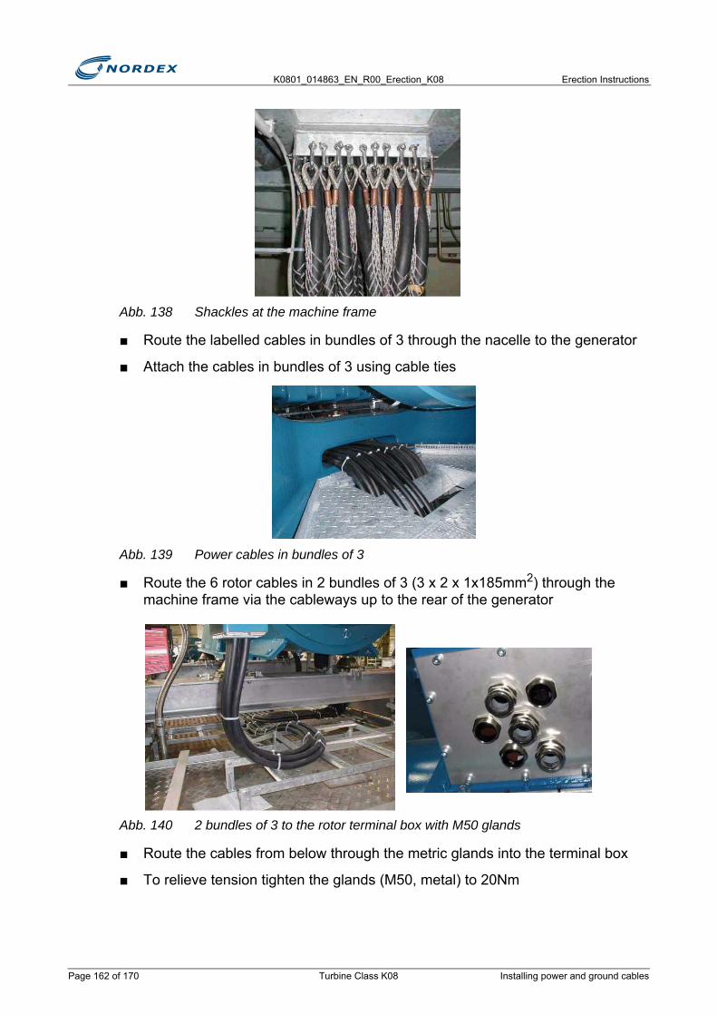
K0801_014863_EN_R00_Erection_K08 Erection Instructions
Abb. 138 Shackles at the machine frame
■ Route the labelled cables in bundles of 3 through the nacelle to the generator
■ Attach the cables in bundles of 3 using cable ties
Abb. 139 Power cables in bundles of 3
■ Route the 6 rotor cables in 2 bundles of 3 (3 x 2 x 1x185mm2) through the machine frame via the cableways up to the rear of the generator
Abb. 140 2 bundles of 3 to the rotor terminal box with M50 glands
■ Route the cables from below through the metric glands into the terminal box
■ To relieve tension tighten the glands (M50, metal) to 20Nm
Page 162 of 170 Turbine Class K08 Installing power and ground cables
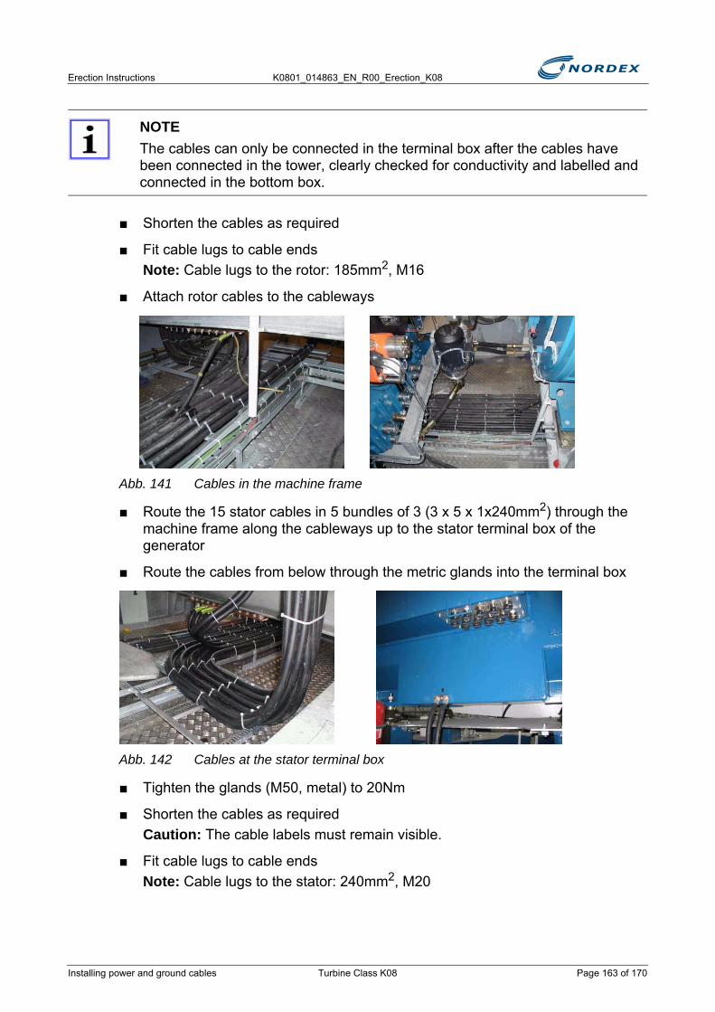
Erection Instructions K0801_014863_EN_R00_Erection_K08
■ Shorten the cables as required
■ Fit cable lugs to cable endsNote: Cable lugs to the rotor: 185mm2, M16
■ Attach rotor cables to the cableways
Abb. 141 Cables in the machine frame
■ Route the 15 stator cables in 5 bundles of 3 (3 x 5 x 1x240mm2) through the machine frame along the cableways up to the stator terminal box of the generator
■ Route the cables from below through the metric glands into the terminal box
Abb. 142 Cables at the stator terminal box
■ Tighten the glands (M50, metal) to 20Nm
■ Shorten the cables as requiredCaution: The cable labels must remain visible.
■ Fit cable lugs to cable endsNote: Cable lugs to the stator: 240mm2, M20
NOTEThe cables can only be connected in the terminal box after the cables have been connected in the tower, clearly checked for conductivity and labelled and connected in the bottom box.
Installing power and ground cables Turbine Class K08 Page 163 of 170
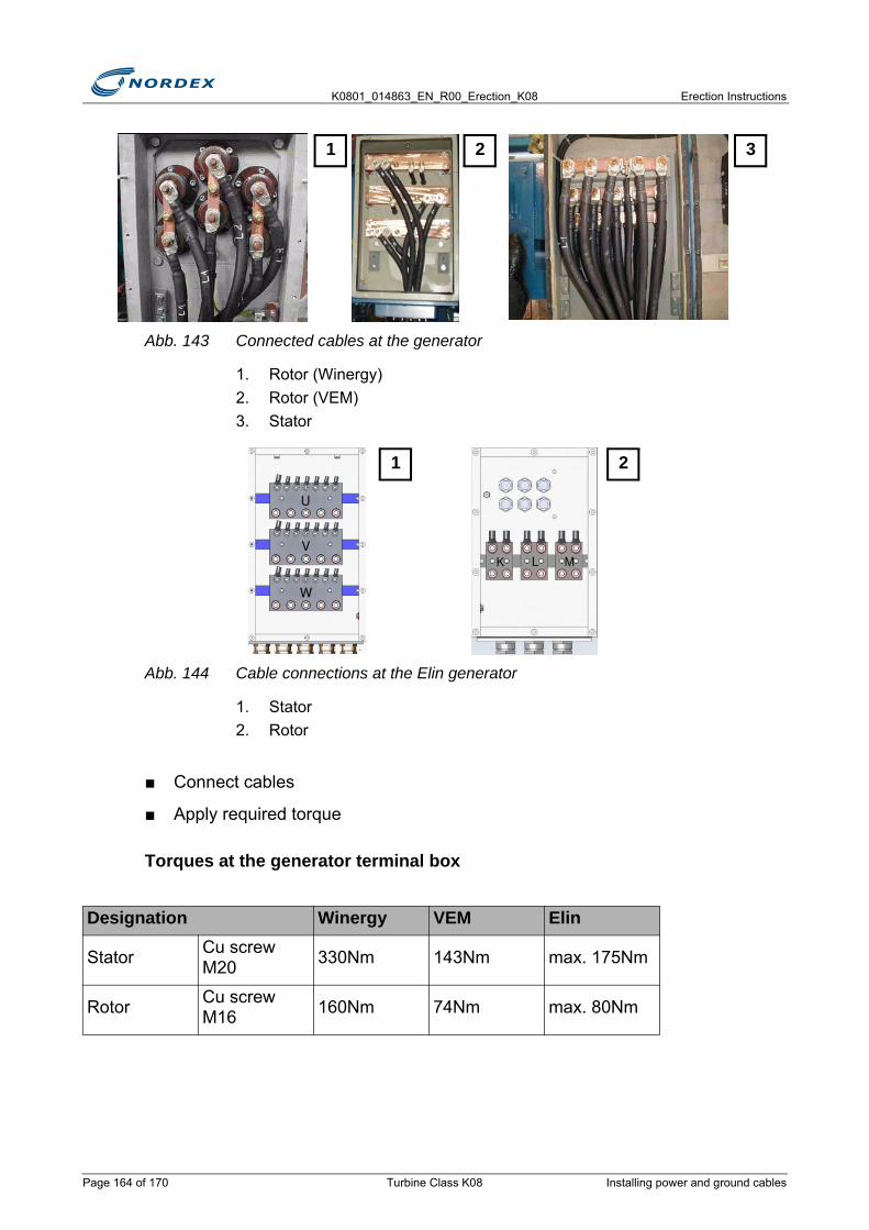
K0801_014863_EN_R00_Erection_K08 Erection Instructions
Abb. 143 Connected cables at the generator
1. Rotor (Winergy)2. Rotor (VEM)3. Stator
Abb. 144 Cable connections at the Elin generator
1. Stator2. Rotor
■ Connect cables
■ Apply required torque
Torques at the generator terminal box
Designation Winergy VEM Elin
Stator Cu screw M20 330Nm 143Nm max. 175Nm
Rotor Cu screw M16 160Nm 74Nm max. 80Nm
321
1 2
Page 164 of 170 Turbine Class K08 Installing power and ground cables
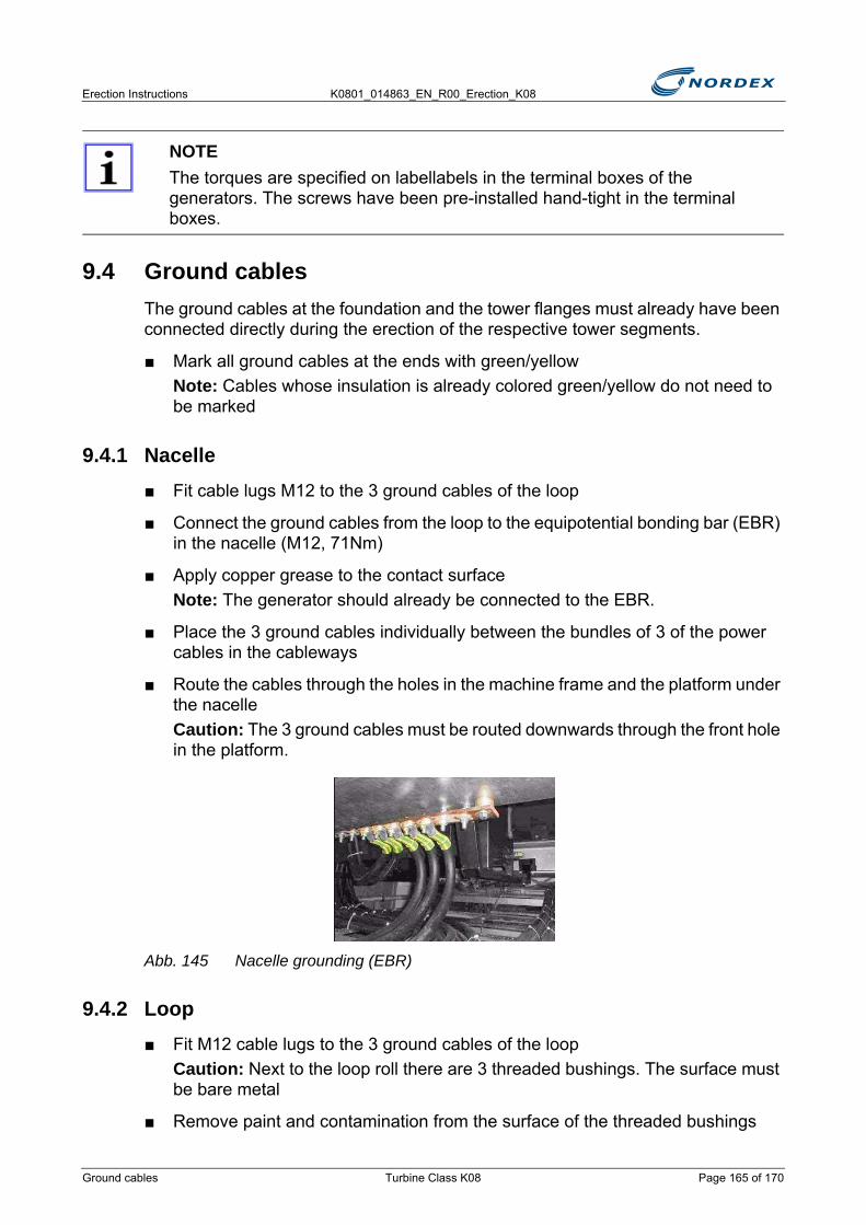
Erection Instructions K0801_014863_EN_R00_Erection_K08
9.4 Ground cablesThe ground cables at the foundation and the tower flanges must already have been connected directly during the erection of the respective tower segments.
■ Mark all ground cables at the ends with green/yellowNote: Cables whose insulation is already colored green/yellow do not need to be marked
9.4.1 Nacelle■ Fit cable lugs M12 to the 3 ground cables of the loop
■ Connect the ground cables from the loop to the equipotential bonding bar (EBR) in the nacelle (M12, 71Nm)
■ Apply copper grease to the contact surfaceNote: The generator should already be connected to the EBR.
■ Place the 3 ground cables individually between the bundles of 3 of the power cables in the cableways
■ Route the cables through the holes in the machine frame and the platform under the nacelleCaution: The 3 ground cables must be routed downwards through the front hole in the platform.
Abb. 145 Nacelle grounding (EBR)
9.4.2 Loop■ Fit M12 cable lugs to the 3 ground cables of the loop
Caution: Next to the loop roll there are 3 threaded bushings. The surface must be bare metal
■ Remove paint and contamination from the surface of the threaded bushings
NOTEThe torques are specified on labellabels in the terminal boxes of the generators. The screws have been pre-installed hand-tight in the terminal boxes.
Ground cables Turbine Class K08 Page 165 of 170
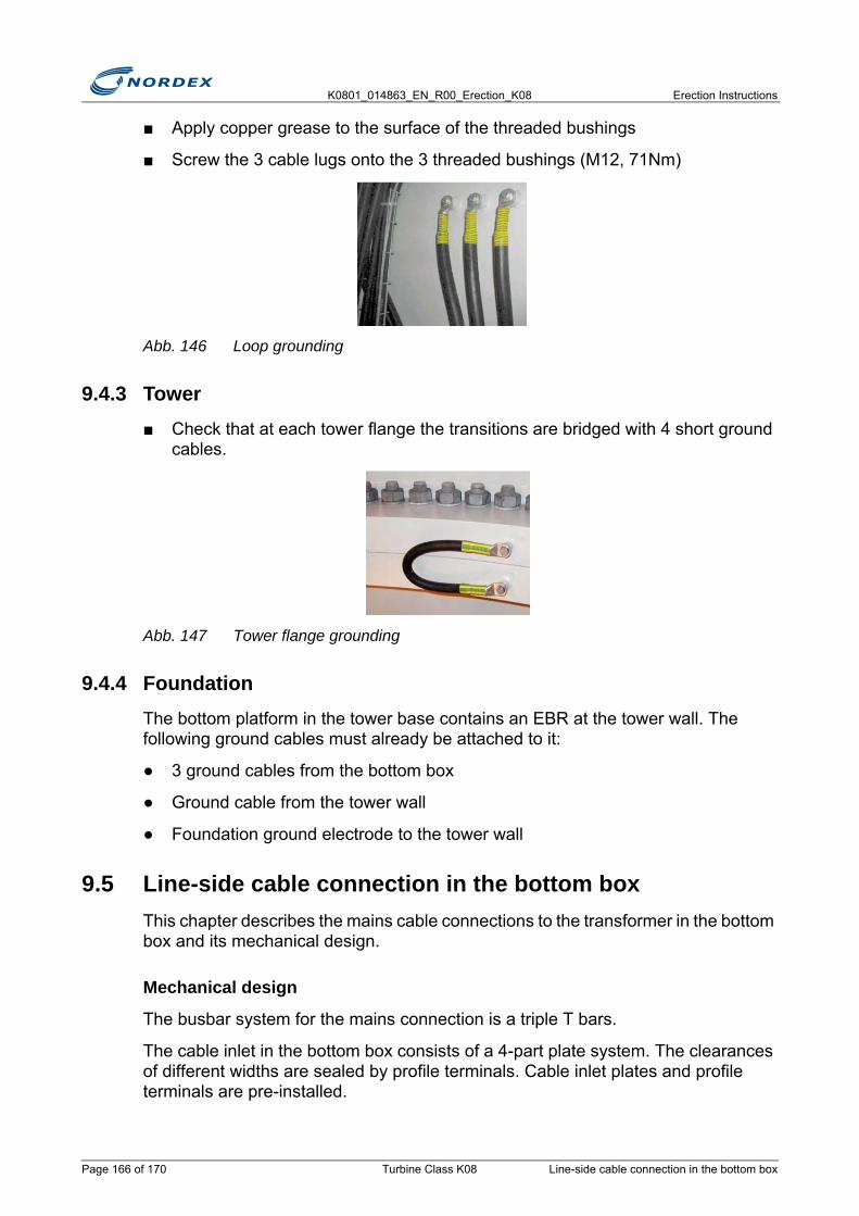
K0801_014863_EN_R00_Erection_K08 Erection Instructions
■ Apply copper grease to the surface of the threaded bushings
■ Screw the 3 cable lugs onto the 3 threaded bushings (M12, 71Nm)
Abb. 146 Loop grounding
9.4.3 Tower■ Check that at each tower flange the transitions are bridged with 4 short ground
cables.
Abb. 147 Tower flange grounding
9.4.4 FoundationThe bottom platform in the tower base contains an EBR at the tower wall. The following ground cables must already be attached to it:
● 3 ground cables from the bottom box
● Ground cable from the tower wall
● Foundation ground electrode to the tower wall
9.5 Line-side cable connection in the bottom boxThis chapter describes the mains cable connections to the transformer in the bottom box and its mechanical design.
Mechanical design
The busbar system for the mains connection is a triple T bars.
The cable inlet in the bottom box consists of a 4-part plate system. The clearances of different widths are sealed by profile terminals. Cable inlet plates and profile terminals are pre-installed.
Page 166 of 170 Turbine Class K08 Line-side cable connection in the bottom box
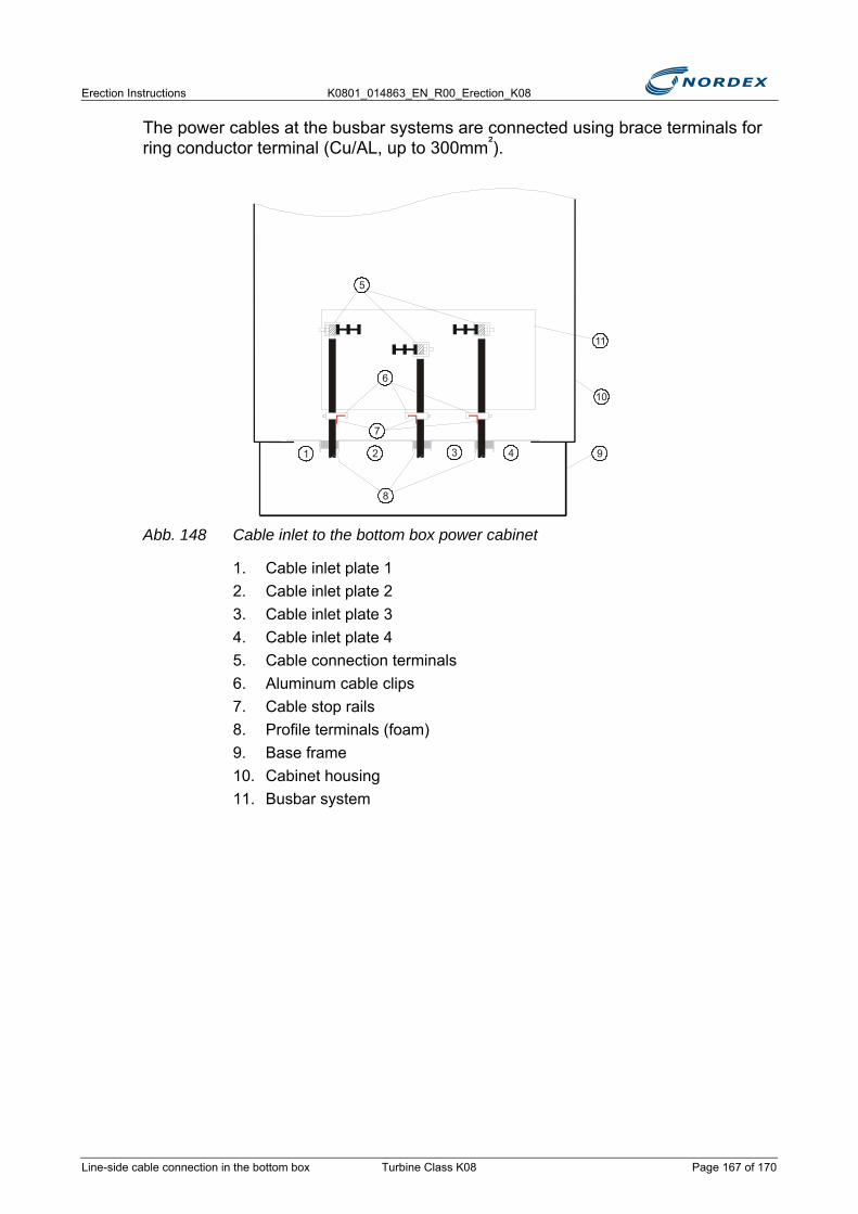
Erection Instructions K0801_014863_EN_R00_Erection_K08
The power cables at the busbar systems are connected using brace terminals for ring conductor terminal (Cu/AL, up to 300mm²).
Abb. 148 Cable inlet to the bottom box power cabinet
1. Cable inlet plate 12. Cable inlet plate 23. Cable inlet plate 34. Cable inlet plate 45. Cable connection terminals6. Aluminum cable clips7. Cable stop rails8. Profile terminals (foam)9. Base frame10. Cabinet housing11. Busbar system
1 92
10
3
11
4
5
6
7
8
Line-side cable connection in the bottom box Turbine Class K08 Page 167 of 170
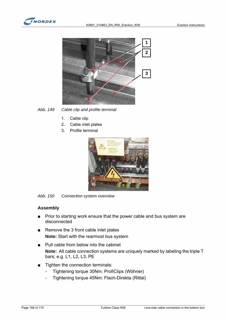
K0801_014863_EN_R00_Erection_K08 Erection Instructions
Abb. 149 Cable clip and profile terminal
1. Cable clip2. Cable inlet plates3. Profile terminal
Abb. 150 Connection system overview
Assembly
■ Prior to starting work ensure that the power cable and bus system are disconnected
■ Remove the 3 front cable inlet platesNote: Start with the rearmost bus system
■ Pull cable from below into the cabinetNote: All cable connection systems are uniquely marked by labeling the triple T bars; e.g. L1, L2, L3, PE
■ Tighten the connection terminals:- Tightening torque 30Nm: ProfiClips (Wöhner)- Tightening torque 45Nm: Flach-Direkta (Rittal)
3
2
1
Page 168 of 170 Turbine Class K08 Line-side cable connection in the bottom box

Erection Instructions K0801_014863_EN_R00_Erection_K08
■ Attach the power cables to the cable stop bars using the existing aluminum cable clips- Aluminum cable clips: Ø 30–34mm, M6, 0.8NmCaution: The use of cable ties is not permitted here.
■ Install the next cable inlet plate
■ Route the ground cable also between the cable inlet plates
■ Install the next cable systems in the same manner
9.6 Installing the control cables
Delivery condition
The cables for control and auxiliary Power system are already pre-installed or rolled up with the loop in the top tower segment.
The supply cable to the Diesel generator is connected to the bottom box during commissioning.
The optic fibre cable is delivered separately to the site.
The control cables in the tower base for the converter cooling, temperature measurement, tower fan and signal exchange to the medium voltage switchgear (only if transformer is in the tower) are provided by Nordex.
Work steps to be performed
■ Lower the cables from the top tower segmentCaution: The control lines must sag approx. 30cm lower in the loop.
■ Routing the cables:- In the cableway next to the power cables- In the cableway above the bottom box
■ Route the cables from the top through the glands into the cabinet
NOTEThe plastic elements for sealing the cable inlet plates must be straight
Do not move the plastic elements during installation. No clearances must be present.
Always use the specified connection terminals and cable clips.
NOTEUse the existing cable brackets. Attach all cables using cable ties.
Installing the control cables Turbine Class K08 Page 169 of 170
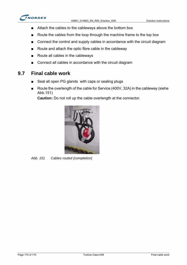
K0801_014863_EN_R00_Erection_K08 Erection Instructions
■ Attach the cables to the cableways above the bottom box
■ Route the cables from the loop through the machine frame to the top box
■ Connect the control and supply cables in accordance with the circuit diagram
■ Route and attach the optic fibre cable in the cableway
■ Route all cables in the cableways
■ Connect all cables in accordance with the circuit diagram
9.7 Final cable work■ Seal all open PG glands with caps or sealing plugs
■ Route the overlength of the cable for Service (400V, 32A) in the cableway (siehe Abb.151)Caution: Do not roll up the cable overlength at the connector.
Abb. 151 Cables routed (completion)
Page 170 of 170 Turbine Class K08 Final cable work

Erection Instructions K0801_014863_EN_R00_Erection_K08
10. Final workFinally the following work must be carried out after erection:
● Cleaning the turbine
● Preservation
● Final inspection
● Checking the documentation
● Exiting the WT
10.1 Cleaning the turbineAll required cleaning agents are delivered in the container.
■ Thoroughly clean the whole turbine:- Remove oil/grease residues using a engine cleaner (general purpose
cellulose thinner).- Clean the inside tower walls.- Clean all platforms (remove sand)
10.2 PreservationThere are 3 preservation options:
● Preservation using paint
● Preservation using wax
● Preservation using metallic coating
INCORRECT PRESERVATIONOnly use special preservatives:
• supplied varnish in the appropriate RAL colors• special spray wax• alkali zinc silicate coating• zinc spray
NOTEOnly use zinc spray if the diameter of the damaged spot in the coating is <15mm.
Derust and degrease the spots to be sprayed prior to preservation.
Apply several layers of zinc spray.
N O T I C E
Cleaning the turbine Turbine Class K08 Page 171 of 174
K0801_014863_EN_R00_Erection_K08 Erection Instructions
10.2.1 Repairing preservations■ All damaged preservation must be repaired in accordance with the appropriate
specification
■ Expert repair of paint damage- Grinding- Cleaning- Priming- Painting
10.2.2 Preserving the yaw bearingsProtective wax has been applied to all unpainted and non-lubricated surfaces of the tooth system of the yaw bearings after the test run in the production hall.
■ Remove protective wax from the tooth profilesNote: The protective wax may only remain on the tooth front ends and at the tooth root area.
■ Only clean the 90° area of the bearing where the pinion and the pitch bearing engage
■ Apply the lubricating grease Ceplattyn BL to the cleaned tooth profiles
10.3 Final inspection■ Check whether the hydraulically preloaded studs (ITH) have been tightened a
2nd time to the nominal preliminary torque.Note: The hydraulically preloaded studs are marked in yellow and red.
■ Only if the authorities require the immediate commissioning of the obstacle lights: - Commission the obstacle lights (or auxiliary lights) in accordance with the
manufacturer instructions and supply them with battery power until commissioning.
■ Only in countries where 110V equipment is mandatory only:- Place the portable isolating transformer in the tower base- Check whether an isolating transformer is permanently installed next to the
top box
■ Use the Erection Report to check whether all work steps have fully been completed and acknowledged in the Erection Report
NOTEThe pitch bearing is only lubricated during commissioning.
Page 172 of 174 Turbine Class K08 Final inspection
Erection Instructions K0801_014863_EN_R00_Erection_K08
■ Hand the first 4 pages of the completed Erection Report to the project manager immediately after erection
■ Hand the completed Erection Report to the project manager after completed erection
10.4 Checking the documentationThe documentation supplied (4 folders) must be complete and stored at the appropriate locations.
■ Check paper documentation:
10.5 Exiting the WT
Prerequisites
● Rotor idles
● Rotor is not lockedNote: The rotor must only be locked in exceptional cases (e.g. if work is not yet completed).
■ Use the rotor lock at the rotor shaft only
■ If the WT must be locked and is likely to remain locked for several days:- Observe the necessary measures in factory standard F010_002
Documentation Storage locationTurbine documentation for nacelle Top box
Turbine documentation for tower base Bottom box
Folder for service reports Bottom box
Red site folder Bottom box
Checking the documentation Turbine Class K08 Page 173 of 174
K0801_014863_EN_R00_Erection_K08 Erection Instructions
■ Leave the whole WT in a clean and arranged condition:- Dispose of all remaining packaging, tools, fasteners, cleaning cloths- Remove all loose items from the nacelle and the rotor hub or secure them- Check that the descender is at the defined location (see "Tower completion")- Close and lock roof window and roof- Lock the access hatch at the hub- Close the access hatches at the tower platform- Disconnect the tower from the Diesel generator- Lock the tower door- Clean the construction site- Fill the erection container completely, correctly and neatly- Collect all transport racks, boxes, tarpaulins, waste at a suitable location for
collection and removal
■ Complete 2 x delivery notes for the return transport of the transport racks
■ Hand the delivery notes to transport company and project manager
Page 174 of 174 Turbine Class K08 Exiting the WT
Related Documents