WORM GEAR SCREW JACKS WORM GEAR SCREW JACK ACCESSORIES TECHNICAL DATA nookindustries.com 274 The specifications and data in this publication are believed to be accurate and reliable. However, it is the responsibility of the product user to determine the suitability of Nook Industries products for a specific application. While defective products will be replaced without charge if promptly returned, no liability is assumed beyond such replacement. WORM GEAR SCREW JACKS 2D/3D CAD 2D/3D CAD IN-LINE ENCODER A 1/2" NPT CONDUIT BOX COVER PLATE CHANNEL A OUTPUT (ORG/WHT WIRE) SUPPLY VOLTAGE +12VDC (RED WIRE) SUPPLY SIGNAL GND (BLACK WIRE) CHANNEL B OUTPUT (VIO/WHT WIRE) ELECTRICAL CONNECTIONS 1 CYCLE 90 DEG A B HI (+12 VDC) LO (0 VDC) OUTPUT CHANNEL WAVEFORMS SUPPLY VOLTAGE CHANNEL OUTPUT CHANNEL A CHANNEL B ANALOG COMMON OPTIONAL PULLUP RESISTOR (50 OHM LOAD MAX) OUTPUT CHANNEL SCHEMATIC (CHANNELS A & B) 1K IN-LINE ENCODER IS INSTALLED BETWEEN THE MOTOR ADAPTER AND MOTOR. Specify the Worm Gear Screw Jack reference number, using the system described on page 296, 317, 336, 345 and 358. EXAMPLE: 2.5-MSJ-U 6:1 / 10BT-1 / 2CA-4E / FT / 24.5 / SE “E” anywhere in this field indicates Encoder HOW TO ORDER AN IN-LINE ENCODER: FRAME SIZE 56C/140TC 180TC/210TC OFFSET A .61 .88 For precise position sensing at the input shaft, an ActionJac™ in-line encoder option may be factory installed between the motor and motor adapter or Right-Angle Reducer. This low- cost option requires minimal space, leaving the extension shaft side of the jack free for clearance, for a rotary limit switch, or for coupling to another jack. The in-line encoder’s quadrature output design allows detec- tion of both speed and direction of shaft rotation. The ActionJac™ in-line encoder option requires an optional motor mount or Right-Angle Reducer. Sensing speed range: 0 -10,000 rpm Pulse Output: 60 Pulses per revolution Supply voltage: +12 Volts DC +/-5% Supply current: 60 mA typical, 115 mA maximum Output drive capability: 250 mA per channel continuous Maximum load: 50 ohms per channel The encoder is face mounted between the motor and motor mount and will offset the length of the motor .61 inches for NEMA 56 and 140 frames and .88 inches for NEMA 180 and 210 frames.

Welcome message from author
This document is posted to help you gain knowledge. Please leave a comment to let me know what you think about it! Share it to your friends and learn new things together.
Transcript
WORM GEARSCREW JACKS
WOR
M G
EAR
SCRE
W J
ACK
ACCE
SSOR
IES
TECH
NICA
L DA
TA
nookindustries.com274The specifications and data in this publication are believed to be accurate and reliable. However, it is the responsibility of the product user to determine the suitability of
Nook Industries products for a specific application. While defective products will be replaced without charge if promptly returned, no liability is assumed beyond such replacement.
WORM GEAR SCREW JACKS
2D/3DCAD2D/3DCADIN-LINE ENCODER
A
1/2" NPT
CONDUITBOX
COVER PLATE
CHANNEL A OUTPUT(ORG/WHT WIRE)
SUPPLY VOLTAGE+12VDC (RED WIRE)
SUPPLY SIGNAL GND(BLACK WIRE)
CHANNEL B OUTPUT(VIO/WHT WIRE)
ELECTRICAL CONNECTIONS
1 CYCLE
90 DEG
A
B
HI (+12 VDC)
LO (0 VDC)
OUTPUT CHANNEL WAVEFORMS
SUPPLY VOLTAGE
CHANNEL OUTPUTCHANNEL ACHANNEL B
ANALOG COMMON
OPTIONAL PULLUPRESISTOR (50 OHM LOAD MAX)
OUTPUT CHANNEL SCHEMATIC(CHANNELS A & B)
1K
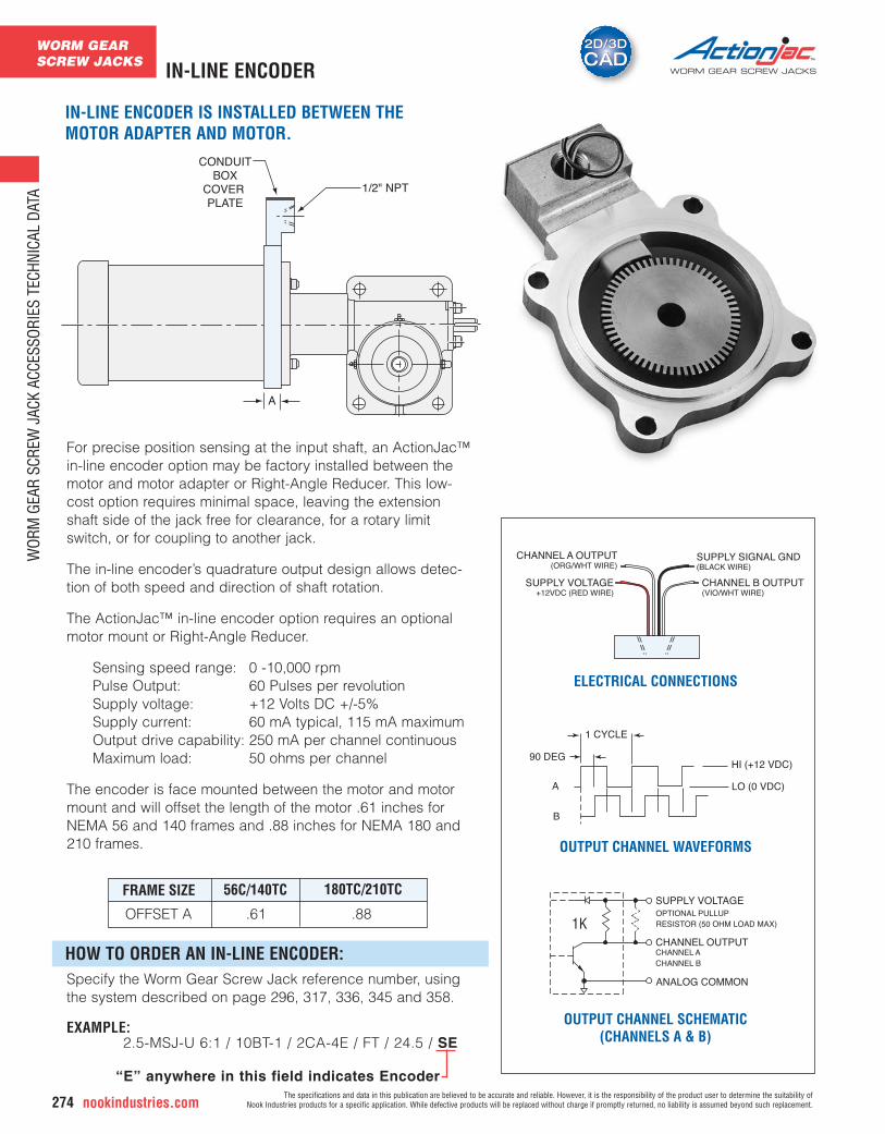
IN-LINE ENCODER IS INSTALLED BETWEEN THEMOTOR ADAPTER AND MOTOR.
Specify the Worm Gear Screw Jack reference number, usingthe system described on page 296, 317, 336, 345 and 358.
EXAMPLE:2.5-MSJ-U 6:1 / 10BT-1 / 2CA-4E / FT / 24.5 / SE
“E” anywhere in this field indicates Encoder
HOW TO ORDER AN IN-LINE ENCODER:
FRAME SIZE 56C/140TC 180TC/210TC
OFFSET A .61 .88
For precise position sensing at the input shaft, an ActionJac™in-line encoder option may be factory installed between themotor and motor adapter or Right-Angle Reducer. This low-cost option requires minimal space, leaving the extensionshaft side of the jack free for clearance, for a rotary limitswitch, or for coupling to another jack.
The in-line encoder’s quadrature output design allows detec-tion of both speed and direction of shaft rotation.
The ActionJac™ in-line encoder option requires an optional motor mount or Right-Angle Reducer.
Sensing speed range: 0 -10,000 rpmPulse Output: 60 Pulses per revolutionSupply voltage: +12 Volts DC +/-5%Supply current: 60 mA typical, 115 mA maximumOutput drive capability: 250 mA per channel continuousMaximum load: 50 ohms per channel
The encoder is face mounted between the motor and motormount and will offset the length of the motor .61 inches forNEMA 56 and 140 frames and .88 inches for NEMA 180 and210 frames.
WORM GEARSCREW JACKS
WOR
M G
EAR
SCRE
W J
ACK
ACCE
SSOR
IES
TECH
NICA
L DA
TA
The specifications and data in this publication are believed to be accurate and reliable. However, it is the responsibility of the product user to determine the suitability of Nook Industries products for a specific application. While defective products will be replaced without charge if promptly returned, no liability is assumed beyond such replacement. nookindustries.com 275
2D/3DCAD2D/3DCAD
WORM GEAR SCREW JACKS MOTORS AND MOTOR MOUNTS
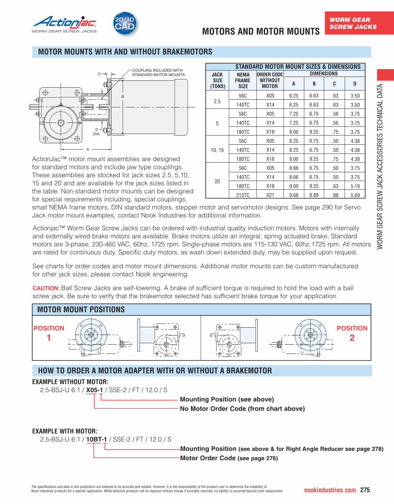
EXAMPLE WITHOUT MOTOR: 2.5-BSJ-U 6:1 / X05-1 / SSE-2 / FT / 12.0 / S
Mounting Position (see above)No Motor Order Code (from chart above)
COUPLING INCLUDED WITHSTANDARD MOTOR MOUNTSC
B
DDIA.
A
JACK SIZE
(TONS)
DIMENSIONS
A B C D
NEMAFRAME
SIZE
STANDARD MOTOR MOUNT SIZES & DIMENSIONSORDER CODE
WITHOUTMOTOR
MOTOR MOUNTS WITH AND WITHOUT BRAKEMOTORS
HOW TO ORDER A MOTOR ADAPTER WITH OR WITHOUT A BRAKEMOTOR
ActionJac™ motor mount assemblies are designed for standard motors and include jaw type couplings. These assemblies are stocked for jack sizes 2.5, 5,10,15 and 20 and are available for the jack sizes listed in the table. Non-standard motor mounts can be designed for special requirements including, special couplings, small NEMA frame motors, DIN standard motors, stepper motor and servomotor designs. See page 290 for ServoJack motor mount examples, contact Nook Industries for additional information.
56C
140TC
56C
140TC
180TC
56C
140TC
180TC
56C
140TC
180TC
213TC
6.25
6.25
7.25
7.25
8.00
8.25
8.25
9.00
8.66
8.66
9.00
9.68
3.50
3.50
3.75
3.75
3.75
4.38
4.38
4.38
3.75
3.75
5.19
5.69
6.63
6.63
6.75
6.75
9.25
6.75
6.75
9.25
6.75
6.75
9.25
8.88
.63
.63
.56
.56
.75
.50
.50
.75
.50
.50
.63
.88
2.5
5
10, 15
20
X05
X14
X05
X14
X18
X05
X14
X18
X05
X14
X18
X21
Actionjac™ Worm Gear Screw Jacks can be ordered with industrial quality induction motors. Motors with internallyand externally wired brake motors are available. Brake motors utilize an integral, spring actuated brake. Standardmotors are 3-phase, 230-460 VAC, 60hz, 1725 rpm. Single-phase motors are 115-130 VAC, 60hz,1725 rpm. All motorsare rated for continuous duty. Specific duty motors, as wash down extended duty, may be supplied upon request.
See charts for order codes and motor mount dimensions. Additional motor mounts can be custom manufactured for other jack sizes, please contact Nook engineering.
CAUTION: Ball Screw Jacks are self-lowering. A brake of sufficient torque is required to hold the load with a ball screw jack. Be sure to verify that the brakemotor selected has sufficient brake torque for your application.
MOTOR MOUNT POSITIONS
POSITION
1POSITION
2
EXAMPLE WITH MOTOR: 2.5-BSJ-U 6:1 / 10BT-1 / SSE-2 / FT / 12.0 / S
Mounting Position (see above & for Right Angle Reducer see page 278)
Motor Order Code (see page 276)
WORM GEARSCREW JACKS
WOR
M G
EAR
SCRE
W J
ACK
ACCE
SSOR
IES
TECH
NICA
L DA
TA
nookindustries.com276The specifications and data in this publication are believed to be accurate and reliable. However, it is the responsibility of the product user to determine the suitability of
Nook Industries products for a specific application. While defective products will be replaced without charge if promptly returned, no liability is assumed beyond such replacement.
WORM GEAR SCREW JACKS
2D/3DCAD2D/3DCAD
PL
LSO1PBF PBR
MCR
TOL
MCF
M B
PBS
F F
MCF TOL
MCR
MCR
MCF
MCFLS02MCR
LS01; FORWARD STROKE LIMIT SWITCHLS02; REVERSE STROKE LIMIT SWITCHPBF = PUSH BUTTON FORWARDPBR = PUSH BUTTON REVERSEPBS = PUSH BUTTON STOP
BRAKE MOTOR CONNECTION DETAIL NOT SHOWN.
CONNECT PER WIRING DIAGRAM FURNISHED WITH MOTOR.
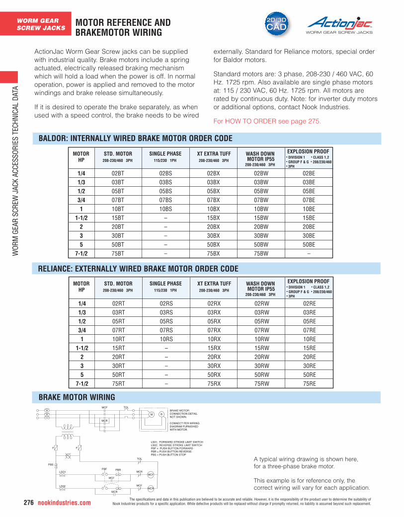
A typical wiring drawing is shown here, for a three-phase brake motor.
This example is for reference only, the correct wiring will vary for each application.
MOTOR REFERENCE ANDBRAKEMOTOR WIRING
BRAKE MOTOR WIRING
STD. MOTOR208-230/460 3PH
SINGLE PHASE115/230 1PH
XT EXTRA TUFF208-230/460 3PH
WASH DOWN MOTOR IP55
208-230/460 3PH
EXPLOSION PROOF• DIVISION 1 • CLASS 1,2• GROUP F & G • 208/230/460• 3PH
MOTORHP
ActionJac Worm Gear Screw jacks can be suppliedwith industrial quality. Brake motors include a springactuated, electrically released braking mechanismwhich will hold a load when the power is off. In normaloperation, power is applied and removed to the motorwindings and brake release simultaneously.
If it is desired to operate the brake separately, as whenused with a speed control, the brake needs to be wired
externally. Standard for Reliance motors, special orderfor Baldor motors.
Standard motors are: 3 phase, 208-230 / 460 VAC, 60Hz. 1725 rpm. Also available are single phase motorsat: 115 / 230 VAC, 60 Hz. 1725 rpm. All motors arerated by continuous duty. Note: for inverter duty motorsor additional options, contact Nook Industries.
For HOW TO ORDER see page 275.
BALDOR: INTERNALLY WIRED BRAKE MOTOR ORDER CODE
RELIANCE: EXTERNALLY WIRED BRAKE MOTOR ORDER CODE
1/41/31/23/41
1-1/2235
7-1/2
02BT03BT05BT07BT10BT15BT20BT30BT50BT75BT
02BS03BS05BS07BS10BS
–––––
02BX03BX05BX07BX10BX15BX20BX30BX50BX75BX
02BW03BW05BW07BW10BW15BW20BW30BW50BW75BW
02BE03BE05BE07BE10BE15BE20BE30BE50BE
–
STD. MOTOR208-230/460 3PH
SINGLE PHASE115/230 1PH
XT EXTRA TUFF208-230/460 3PH
WASH DOWN MOTOR IP55
208-230/460 3PH
EXPLOSION PROOF• DIVISION 1 • CLASS 1,2• GROUP F & G • 208/230/460• 3PH
MOTORHP
1/41/31/23/41
1-1/2235
7-1/2
02RT03RT05RT07RT10RT15RT20RT30RT50RT75RT
02RS03RS05RS07RS10RS
–––––
02RX03RX05RX07RX10RX15RX20RX30RX50RX75RX
02RW03RW05RW07RW10RW15RW20RW30RW50RW75RW
02RE03RE05RE07RE10RE15RE20RE30RE50RE75RE
WORM GEARSCREW JACKS
WOR
M G
EAR
SCRE
W J
ACK
ACCE
SSOR
IES
TECH
NICA
L DA
TA
The specifications and data in this publication are believed to be accurate and reliable. However, it is the responsibility of the product user to determine the suitability of Nook Industries products for a specific application. While defective products will be replaced without charge if promptly returned, no liability is assumed beyond such replacement. nookindustries.com 277
WORM GEAR SCREW JACKS
A
B
øH
øD
øCL øE
øF (4-HOLE
K
METRIC MOTOR MOUNTS
IEC FRAMEMOTOR SIZE
PARTNUMBERMODEL
AREF B øC øD øE øF øH LK
57.5
57.5
76
76
76
76
90
90
90
90
115
115
115
115
140
140
140
140
150
150
100
100
114
114
120
120
135
135
145
145
180
170
180
180
207
207
217
217
230
230
120
80
140
90
160
105
160
105
200
120
200
120
200
140
200
140
250
160
250
160
64
64
70
70
85
85
85
85
85
85
98
96
96
96
116
116
116
116
134
134
100
65
115
75
130
85
130
85
165
100
165
100
165
115
165
115
215
130
215
130
8.5
6
9
6
9
7
9
7
11
7
11
7
11
9
11
9
13
9
13
9
80
50
95
60
110
70
110
70
130
80
130
80
130
95
130
95
180
110
180
110
3.5
3.0
4
3.5
4.5
4
4.5
4
4.5
4.5
4.5
4.5
4.5
4.5
4.5
4.5
5
5
5
5
7
6
8
8
10
10
10
10
12
12
12
12
12
12
12
12
14
14
14
14
56B5
56B14
63B5
63B14
71B5
71B14
71B5
71B14
80B5
80B14
80B5
80B14
90B5
90B14
90B5
90B14
100B5
100B14
100B5
100B14
EM05-BSJEM05-MSJ
EM1-BSJEM1-MSJ
EM2.5-BSJEM2.5-MSJ
EM5-BSJEM5-MSJ
EM10-BSJEM10-MSJ
EM20-BSJEM-20-MSJ
8026-01-00
8020-01-00
7825-01-00
7826-01-00
7821-01-00
7822-01-00
7785-01-00
7773-01-00
7787-01-00
7774-01-00
7795-01-00
7791-01-00
7790-01-00
7796-01-00
7798-01-00
7799-01-00
7802-01-00
7803-01-00
7809-01-00
7811-01-00
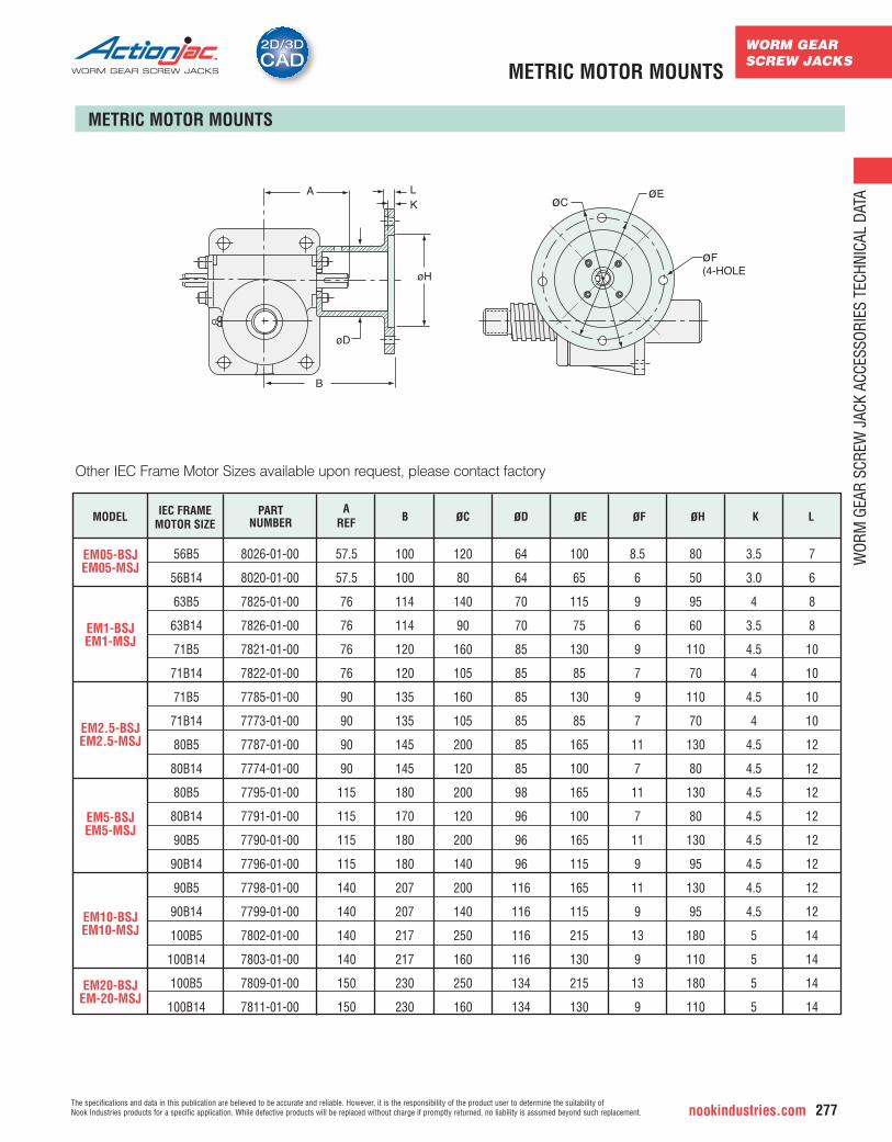
Other IEC Frame Motor Sizes available upon request, please contact factory
METRIC MOTOR MOUNTS
WORM GEARSCREW JACKS
WOR
M G
EAR
SCRE
W J
ACK
ACCE
SSOR
IES
TECH
NICA
L DA
TA
nookindustries.com278The specifications and data in this publication are believed to be accurate and reliable. However, it is the responsibility of the product user to determine the suitability of
Nook Industries products for a specific application. While defective products will be replaced without charge if promptly returned, no liability is assumed beyond such replacement.
WORM GEAR SCREW JACKS
2D/3DCAD2D/3DCADRIGHT ANGLE REDUCERS
NEMAMOTOR MOUNT
E
D
C
FJ
H
G
A
B
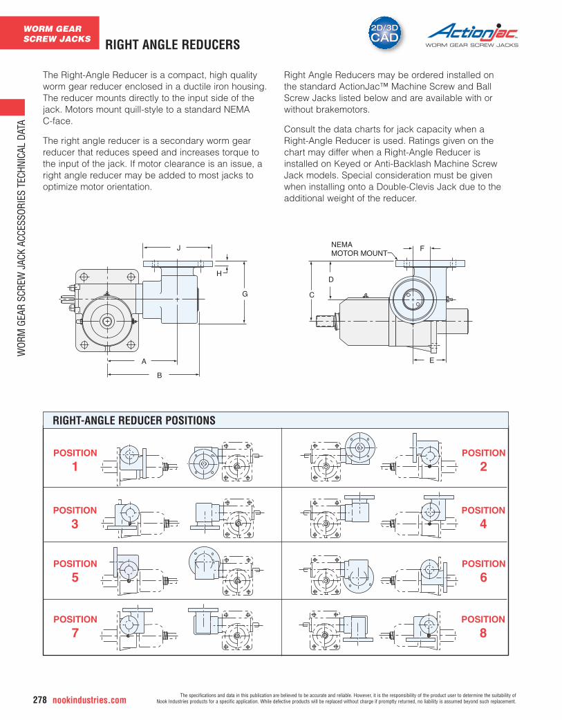
The Right-Angle Reducer is a compact, high qualityworm gear reducer enclosed in a ductile iron housing.The reducer mounts directly to the input side of thejack. Motors mount quill-style to a standard NEMA C-face.
The right angle reducer is a secondary worm gearreducer that reduces speed and increases torque tothe input of the jack. If motor clearance is an issue, aright angle reducer may be added to most jacks tooptimize motor orientation.
Right Angle Reducers may be ordered installed onthe standard ActionJac™ Machine Screw and BallScrew Jacks listed below and are available with orwithout brakemotors.
Consult the data charts for jack capacity when aRight-Angle Reducer is used. Ratings given on thechart may differ when a Right-Angle Reducer isinstalled on Keyed or Anti-Backlash Machine ScrewJack models. Special consideration must be givenwhen installing onto a Double-Clevis Jack due to theadditional weight of the reducer.
RIGHT-ANGLE REDUCER POSITIONS
POSITION
1
POSITION
3
POSITION
5
POSITION
7
POSITION
2
POSITION
4
POSITION
6
POSITION
8
WORM GEARSCREW JACKS
WOR
M G
EAR
SCRE
W J
ACK
ACCE
SSOR
IES
TECH
NICA
L DA
TA
The specifications and data in this publication are believed to be accurate and reliable. However, it is the responsibility of the product user to determine the suitability of Nook Industries products for a specific application. While defective products will be replaced without charge if promptly returned, no liability is assumed beyond such replacement. nookindustries.com 279
2D/3DCAD2D/3DCAD
WORM GEAR SCREW JACKS
JACK MODEL-RATIO
REDUCERRATIO
TRAVEL RATEIN/MIN. @1725 RPM
BRAKEMOTOR
HP
DYNAMICCAPACITY*
(LBS.)
ORDER CODE**W/1-PHMOTOR
W/3-PHMOTOR
WITHOUTMOTOR
MOTORSIZE
REDUCER DIMENSIONS
A B C D E F G H J
JACK MODEL-RATIO
REDUCERRATIO
TRAVEL RATEIN/MIN. @1725 RPM
BRAKEMOTOR
HP
DYNAMICCAPACITY*
(LBS.)
ORDER CODEW/1-PHMOTOR
W/3-PHMOTOR
WITHOUTMOTOR
MOTORSIZE
REDUCER DIMENSIONS
A B C D E F G H J
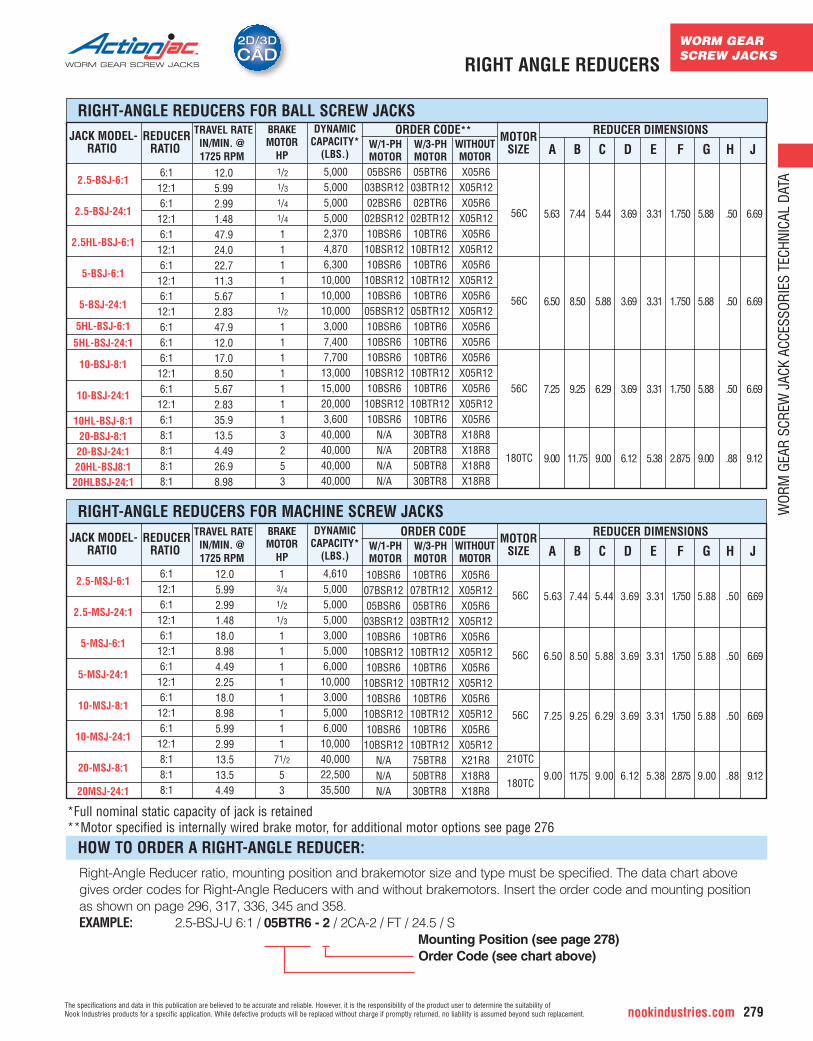
Right-Angle Reducer ratio, mounting position and brakemotor size and type must be specified. The data chart abovegives order codes for Right-Angle Reducers with and without brakemotors. Insert the order code and mounting positionas shown on page 296, 317, 336, 345 and 358.EXAMPLE: 2.5-BSJ-U 6:1 / 05BTR6 - 2 / 2CA-2 / FT / 24.5 / S
Mounting Position (see page 278)Order Code (see chart above)
RIGHT-ANGLE REDUCERS FOR BALL SCREW JACKS
RIGHT-ANGLE REDUCERS FOR MACHINE SCREW JACKS
HOW TO ORDER A RIGHT-ANGLE REDUCER:
*Full nominal static capacity of jack is retained**Motor specified is internally wired brake motor, for additional motor options see page 276
2.5-MSJ-6:1
2.5-MSJ-24:1
5-MSJ-6:1
5-MSJ-24:1
10-MSJ-8:1
10-MSJ-24:1
20-MSJ-8:1
20MSJ-24:1
2.5-BSJ-6:1
2.5-BSJ-24:1
2.5HL-BSJ-6:1
5-BSJ-6:1
5-BSJ-24:1
5HL-BSJ-6:1
5HL-BSJ-24:1
10-BSJ-8:1
10-BSJ-24:1
10HL-BSJ-8:120-BSJ-8:120-BSJ-24:120HL-BSJ8:120HLBSJ-24:1
6:112:16:112:16:112:16:112:16:112:16:16:16:112:16:112:16:18:18:18:18:1
6:112:16:112:16:112:16:112:16:112:16:112:18:18:18:1
12.05.992.991.4847.924.022.711.35.672.8347.912.017.08.505.672.8335.913.54.4926.98.98
12.05.992.991.4818.08.984.492.2518.08.985.992.9913.513.54.49
1/21/31/41/411111
1/211111113253
13/41/21/311111111
71/253
5,0005,0005,0005,0002,3704,8706,30010,00010,00010,0003,0007,4007,70013,00015,00020,0003,60040,00040,00040,00040,000
4,6105,0005,0005,0003,0005,0006,00010,0003,0005,0006,00010,00040,00022,50035,500
56C
56C
56C
180TC
56C
56C
56C
210TC
180TC
5.63
6.50
7.25
9.00
7.44
8.50
9.25
11.75
5.44
5.88
6.29
9.00
3.69
3.69
3.69
6.12
3.31
3.31
3.31
5.38
1.750
1.750
1.750
2.875
5.88
5.88
5.88
9.00
.50
.50
.50
.88
6.69
6.69
6.69
9.12
5.63
6.50
7.25
9.00
7.44
8.50
9.25
11.75
5.44
5.88
6.29
9.00
3.69
3.69
3.69
6.12
3.31
3.31
3.31
5.38
1.750
1.750
1.750
2.875
5.88
5.88
5.88
9.00
.50
.50
.50
.88
6.69
6.69
6.69
9.12
05BSR603BSR1202BSR602BSR1210BSR610BSR1210BSR610BSR1210BSR605BSR1210BSR610BSR610BSR610BSR1210BSR610BSR1210BSR6
N/AN/AN/AN/A
05BTR603BTR1202BTR602BTR1210BTR610BTR1210BTR610BTR1210BTR605BTR1210BTR610BTR610BTR610BTR1210BTR610BTR1210BTR630BTR820BTR850BTR830BTR8
X05R6X05R12X05R6X05R12X05R6X05R12X05R6X05R12X05R6X05R12X05R6X05R6X05R6X05R12X05R6X05R12X05R6X18R8X18R8X18R8X18R8
10BSR607BSR1205BSR603BSR1210BSR610BSR1210BSR610BSR1210BSR610BSR1210BSR610BSR12
N/AN/AN/A
10BTR607BTR1205BTR603BTR1210BTR610BTR1210BTR610BTR1210BTR610BTR1210BTR610BTR1275BTR850BTR830BTR8
X05R6X05R12X05R6X05R12X05R6X05R12X05R6X05R12X05R6X05R12X05R6X05R12X21R8X18R8X18R8
RIGHT ANGLE REDUCERS
WORM GEARSCREW JACKS
WOR
M G
EAR
SCRE
W J
ACK
ACCE
SSOR
IES
TECH
NICA
L DA
TA
nookindustries.com280The specifications and data in this publication are believed to be accurate and reliable. However, it is the responsibility of the product user to determine the suitability of
Nook Industries products for a specific application. While defective products will be replaced without charge if promptly returned, no liability is assumed beyond such replacement.
WORM GEAR SCREW JACKSBELLOWS BOOTS
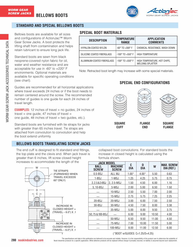
Bellows boots are available for all sizesand configurations of ActionJac™ WormGear Screw Jacks. A boot protects thelifting shaft from contamination and helpsretain lubricant to ensure long jack life.
Standard boots are sewn from blackneoprene-covered nylon fabric for oil,water and weather resistance and areacceptable for use in -60° to +220° Fenvironments. Optional materials areavailable for specific operating conditions(see chart).
Guides are recommended for all horizontal applicationswhere travel exceeds 24 inches or if the boot needs toremain centered around the screw. The recommendednumber of guides is one guide for each 24 inches oftravel length.
EXAMPLES: 12 inches of travel = no guides, 24 inches oftravel = one guide, 47 inches of travel = one guide, 48 inches of travel = two guides, etc.).
Standard boots are furnished with tie straps for jacks with greater than 65 inches travel. Tie straps are attached from convolution to convolution and help the boot extend uniformly.
SPECIAL END CONFIGURATIONS
SQUARECUFF
FLANGEEND
SQUAREFLANGE
W
D
C
TIE STRAPS(FURNISHED WHEN TRAVEL EXCEEDS 65" ONLY)
INCREASE INCLOSED HEIGHT =(TRAVEL – 6.0") X .1
INCREASE INCLOSED HEIGHT =(TRAVEL – 6.0") X .1
JACK MODEL MAX. SCREWDIA (REF.)BALL
SCREWWC
DIAD
DIAMACHINESCREW
The end cuff is designed to fit standard end fittings,the top plate and the clevis end. When jack travel isgreater than 6 inches, lift screw closed heightincreases to accommodate the length of the
collapsed boot convolutions. For standard boots theincrease in closed height is calculated using theformula shown.
STANDARD AND SPECIAL BELLOWS BOOTS
BELLOWS BOOTS TRANSLATING SCREW JACKS
0.5-BSJ
1-BSJ
2,2.5&3-BSJ
5, 10-BSJ
—
—20-BSJ
30-BSJ
—
—
—
—
ALL MJ
1-MSJ
2, 2.5-MSJ
5-MSJ
10-MSJ
15-MSJ
20-MSJ
30-MSJ
35-MSJ
—50-MSJ
75-MSJ
100-MSJ
0.63
0.75
1.16
1.50
2.00
2.25
2.50
3.38
3.75
4.00
4.50
5.00
6.00
1.00*
1.25
1.50
2.00
2.50
2.75
3.00
4.50
5.00
6.00
6.50
7.00
8.00
4.00*
4.25
4.50
5.00
5.50
5.75
6.00
7.50
8.00
9.00
9.50
10.00
11.00
5.50
5.75
6.00
6.50
7.00
7.25
7.50
8.00
9.50
10.50
11.00
11.50
12.50
Note: Retracted boot length may increase with some special materials.
DESCRIPTION TEMPERATURERANGE
APPLICATIONCOMMENTS
SPECIAL BOOT MATERIALS
HYPALON-COATED NYLON -60° TO +300° F CHEMICAL RESISTANCE, WASH DOWN
SILICONE COATED FIBERGLASS -100° TO +550° F HIGH TEMPERATURE
ALUMINUM-COATED FIBERGLASS -100° TO +550° F HIGH TEMPERATURE, HOT CHIPS,WELDING SPLATTER
(*BOOT w/GUIDES: C=1.25/D=4.25)
50,75 &100-BSJ
WORM GEARSCREW JACKS
WOR
M G
EAR
SCRE
W J
ACK
ACCE
SSOR
IES
TECH
NICA
L DA
TA
The specifications and data in this publication are believed to be accurate and reliable. However, it is the responsibility of the product user to determine the suitability of Nook Industries products for a specific application. While defective products will be replaced without charge if promptly returned, no liability is assumed beyond such replacement. nookindustries.com 281
2D/3DCAD2D/3DCAD
WORM GEAR SCREW JACKS
BELLOWS BOOTS FOR ROTATING SCREW JACK
HOW TO ORDER BOOTS FOR A TRANSLATING AND ROTATING SCREW JACK
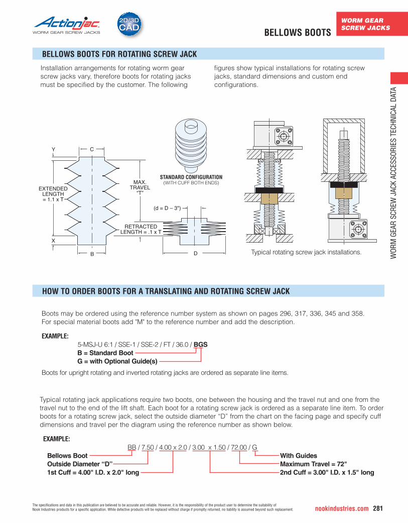
Installation arrangements for rotating worm gearscrew jacks vary, therefore boots for rotating jacksmust be specified by the customer. The following
figures show typical installations for rotating screwjacks, standard dimensions and custom endconfigurations.
Typical rotating jack applications require two boots, one between the housing and the travel nut and one from thetravel nut to the end of the lift shaft. Each boot for a rotating screw jack is ordered as a separate line item. To orderboots for a rotating screw jack, select the outside diameter “D” from the chart on the facing page and specify cuffdimensions and travel per the diagram using the reference number as shown below.
EXAMPLE:BB / 7.50 / 4.00 x 2.0 / 3.00 x 1.50 / 72.00 / G
Bellows Boot With GuidesOutside Diameter “D” Maximum Travel = 72"1st Cuff = 4.00" I.D. x 2.0" long 2nd Cuff = 3.00" I.D. x 1.5" long
CY
X
B
EXTENDEDLENGTH= 1.1 x T
MAX.TRAVEL
“T”
RETRACTEDLENGTH = .1 x T
(d = D – 3")
D
STANDARD CONFIGURATION(WITH CUFF BOTH ENDS)
Typical rotating screw jack installations.
Boots may be ordered using the reference number system as shown on pages 296, 317, 336, 345 and 358. For special material boots add "M" to the reference number and add the description.
EXAMPLE:5-MSJ-U 6:1 / SSE-1 / SSE-2 / FT / 36.0 / BGSB = Standard BootG = with Optional Guide(s)
Boots for upright rotating and inverted rotating jacks are ordered as separate line items.
BELLOWS BOOTS
WORM GEARSCREW JACKS
WOR
M G
EAR
SCRE
W J
ACK
ACCE
SSOR
IES
TECH
NICA
L DA
TA
nookindustries.com282The specifications and data in this publication are believed to be accurate and reliable. However, it is the responsibility of the product user to determine the suitability of
Nook Industries products for a specific application. While defective products will be replaced without charge if promptly returned, no liability is assumed beyond such replacement.
WORM GEAR SCREW JACKS
2D/3DCAD2D/3DCADROTARY LIMIT SWITCH
SPECIFY: • Limit Switch code (see table to right)• Mounting Position (1 through 8 see page 283)• Close or Extended Mount (C or E)
Insert the correct designation in the ActionJac™ Worm Gear Screw Jack reference number (see page 296 and 317for more information on jack reference numbers).
EXAMPLE: 2.5-MSJ-U 6:1 / 103-1 / 2CA-4E / FT / 24.5 / S
Extension shaft designation
Examples of rotary limit switch designations:2CA-4C = Rotary Limit Switch, 2-circuit, SPDT, position 4, close mount4CE-1E = Rotary Limit Switch, 4-circuit, DPDT, position 1, extended mountPTA-8C = Rotary Limit Switch with potentiometer, 2 SPDT’s, position 8, close mount
C = Close mount on E = Extended mount (see following page)“dash” number designates mounting position
IMPORTANT: These designation numbers are not complete part numbers. These assemblies contain gearreducers with ratios that vary according to the model and travel of the jack. If you are ordering a replacementswitch assembly, complete information on the jack is required.
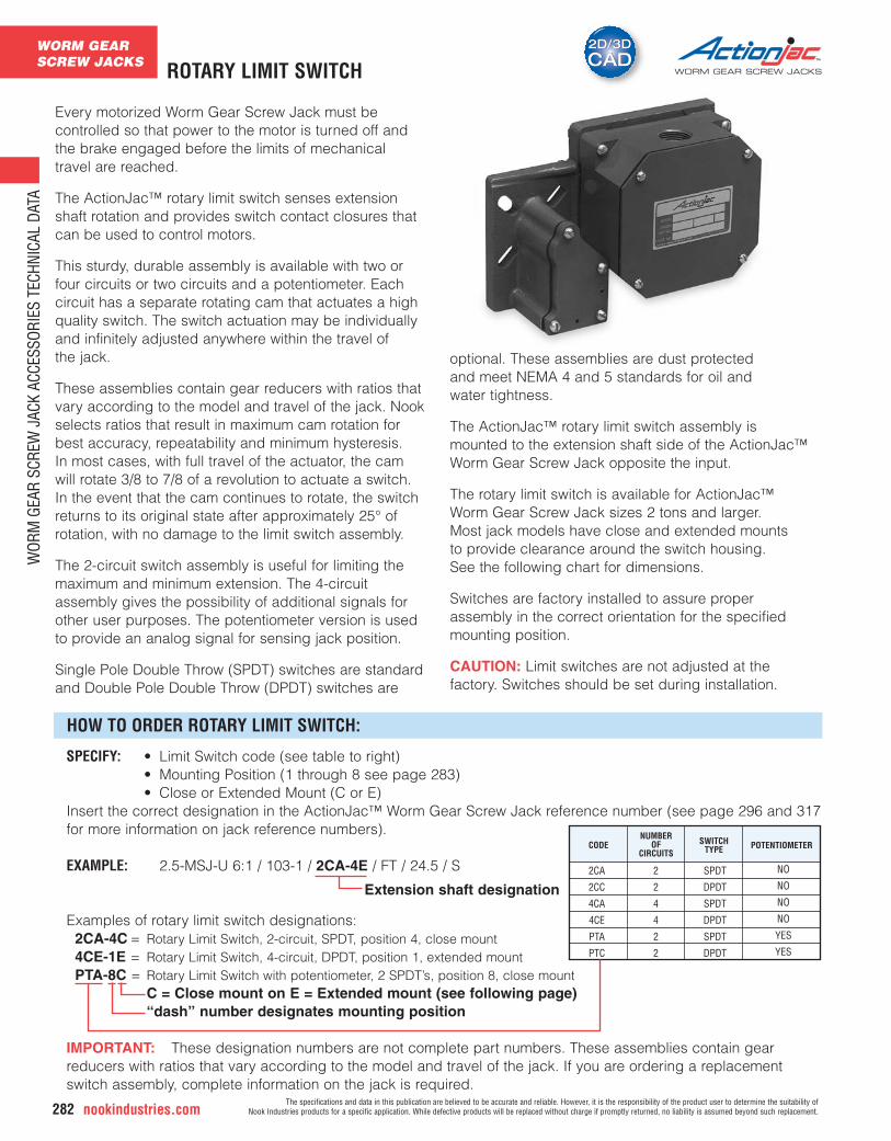
Every motorized Worm Gear Screw Jack must becontrolled so that power to the motor is turned off andthe brake engaged before the limits of mechanicaltravel are reached.
The ActionJac™ rotary limit switch senses extensionshaft rotation and provides switch contact closures thatcan be used to control motors.
This sturdy, durable assembly is available with two orfour circuits or two circuits and a potentiometer. Eachcircuit has a separate rotating cam that actuates a highquality switch. The switch actuation may be individuallyand infinitely adjusted anywhere within the travel of the jack.
These assemblies contain gear reducers with ratios thatvary according to the model and travel of the jack. Nookselects ratios that result in maximum cam rotation forbest accuracy, repeatability and minimum hysteresis. In most cases, with full travel of the actuator, the camwill rotate 3/8 to 7/8 of a revolution to actuate a switch.In the event that the cam continues to rotate, the switchreturns to its original state after approximately 25° ofrotation, with no damage to the limit switch assembly.
The 2-circuit switch assembly is useful for limiting themaximum and minimum extension. The 4-circuitassembly gives the possibility of additional signals forother user purposes. The potentiometer version is usedto provide an analog signal for sensing jack position.
Single Pole Double Throw (SPDT) switches are standardand Double Pole Double Throw (DPDT) switches are
optional. These assemblies are dust protected and meet NEMA 4 and 5 standards for oil and water tightness.
The ActionJac™ rotary limit switch assembly is mounted to the extension shaft side of the ActionJac™Worm Gear Screw Jack opposite the input.
The rotary limit switch is available for ActionJac™ Worm Gear Screw Jack sizes 2 tons and larger. Most jack models have close and extended mounts to provide clearance around the switch housing. See the following chart for dimensions.
Switches are factory installed to assure properassembly in the correct orientation for the specifiedmounting position.
CAUTION: Limit switches are not adjusted at thefactory. Switches should be set during installation.
CODE POTENTIOMETERNUMBER
OFCIRCUITS
SWITCHTYPE
HOW TO ORDER ROTARY LIMIT SWITCH:
2CA
2CC
4CA
4CE
PTA
PTC
2
2
4
4
2
2
SPDT
DPDT
SPDT
DPDT
SPDT
DPDT
NO
NO
NO
NO
YES
YES
WORM GEARSCREW JACKS
WOR
M G
EAR
SCRE
W J
ACK
ACCE
SSOR
IES
TECH
NICA
L DA
TA
The specifications and data in this publication are believed to be accurate and reliable. However, it is the responsibility of the product user to determine the suitability of Nook Industries products for a specific application. While defective products will be replaced without charge if promptly returned, no liability is assumed beyond such replacement. nookindustries.com 283
WORM GEAR SCREW JACKS
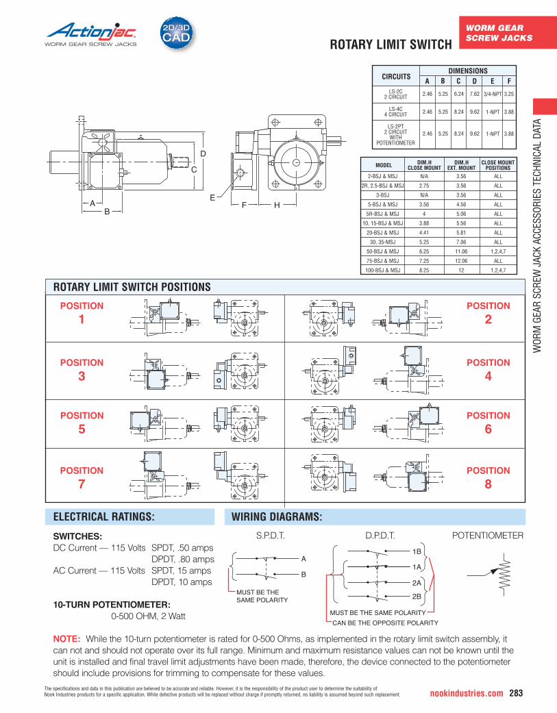
SWITCHES:DC Current — 115 Volts SPDT, .50 amps
DPDT, .80 ampsAC Current — 115 Volts SPDT, 15 amps
DPDT, 10 amps
10-TURN POTENTIOMETER:0-500 OHM, 2 Watt
NOTE: While the 10-turn potentiometer is rated for 0-500 Ohms, as implemented in the rotary limit switch assembly, itcan not and should not operate over its full range. Minimum and maximum resistance values can not be known until theunit is installed and final travel limit adjustments have been made, therefore, the device connected to the potentiometershould include provisions for trimming to compensate for these values.
CIRCUITSDIMENSIONS
A B C D E F
MODEL DIM.HCLOSE MOUNT
DIM.HEXT. MOUNT
CLOSE MOUNTPOSITIONS
D
EA
B
C
F H
MUST BE THE SAME POLARITY
A
B
1B
1A
2B
2A
MUST BE THE SAME POLARITY
CAN BE THE OPPOSITE POLARITY
ELECTRICAL RATINGS: WIRING DIAGRAMS:
ROTARY LIMIT SWITCH POSITIONS
POSITION
1
POSITION
3
POSITION
5
POSITION
7
POSITION
2
POSITION
4
POSITION
6
POSITION
8
S.P.D.T. D.P.D.T. POTENTIOMETER
LS-2C2 CIRCUIT
LS-4C4 CIRCUIT
LS-2PT2 CIRCUIT
WITHPOTENTIOMETER
2-BSJ & MSJ
2R, 2.5-BSJ & MSJ
3-BSJ
5-BSJ & MSJ
5R-BSJ & MSJ
10, 15-BSJ & MSJ
20-BSJ & MSJ
30, 35-MSJ
50-BSJ & MSJ
75-BSJ & MSJ
100-BSJ & MSJ
N/A
2.75
N/A
3.56
4
3.88
4.41
5.25
6.25
7.25
8.25
3.56
3.56
3.56
4.56
5.06
5.56
5.81
7.06
11.06
12.06
12
ALL
ALL
ALL
ALL
ALL
ALL
ALL
ALL
1,2,4,7
ALL
1,2,4,7
3/4-NPT
1-NPT
1-NPT
3.25
3.88
3.88
2.46
2.46
2.46
5.25
5.25
5.25
6.24
8.24
8.24
7.62
9.62
9.62
ROTARY LIMIT SWITCH
WORM GEARSCREW JACKS
WOR
M G
EAR
SCRE
W J
ACK
ACCE
SSOR
IES
TECH
NICA
L DA
TA
nookindustries.com284The specifications and data in this publication are believed to be accurate and reliable. However, it is the responsibility of the product user to determine the suitability of
Nook Industries products for a specific application. While defective products will be replaced without charge if promptly returned, no liability is assumed beyond such replacement.
WORM GEAR SCREW JACKS
2D/3DCAD2D/3DCADFLEXIBLE COUPLINGS
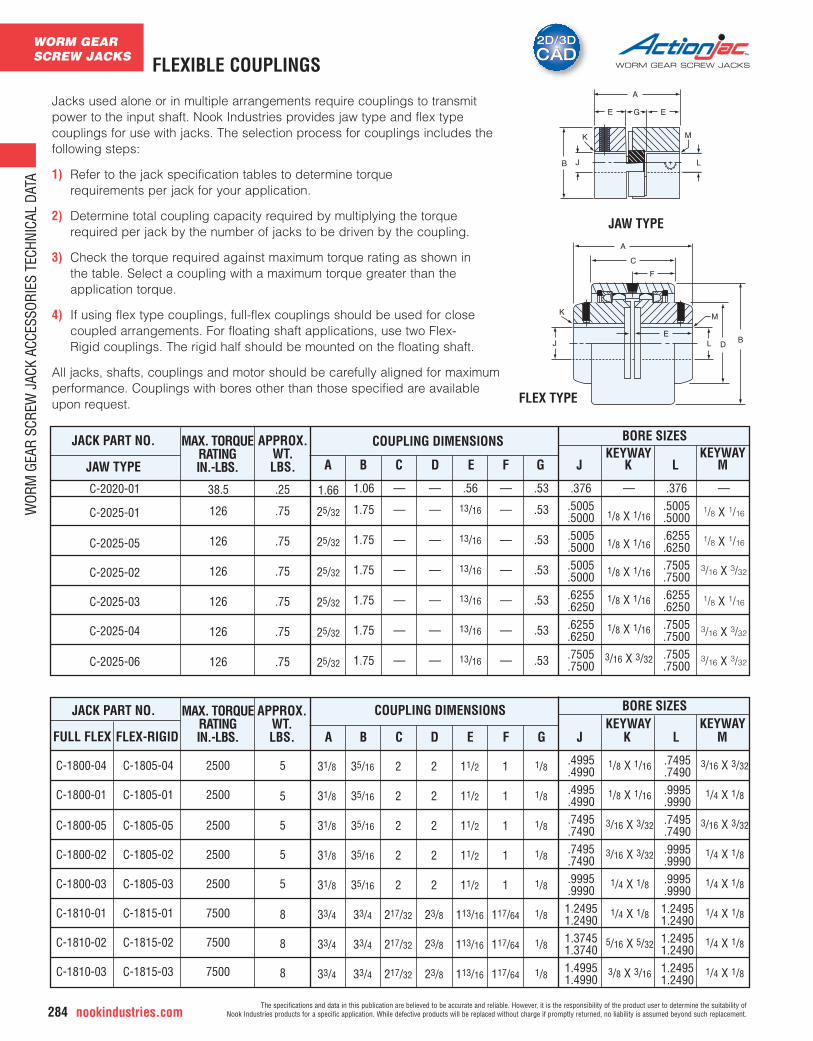
FLEX TYPE
E
K M
A
C
J L DB
F
A
E EG
K
B J
M
L
JAW TYPE
JACK PART NO.
JAW TYPE
MAX. TORQUERATINGIN.-LBS.
COUPLING DIMENSIONS BORE SIZESKEYWAY
APPROX.WT.LBS.
KEYWAYA B C D E F G J K L M
JACK PART NO. MAX. TORQUERATINGIN.-LBS. A B
BORE SIZES
FLEX-RIGIDKEYWAY
APPROX.WT.LBS. C D E F G
KEYWAYJ K L MFULL FLEX
COUPLING DIMENSIONS
Jacks used alone or in multiple arrangements require couplings to transmitpower to the input shaft. Nook Industries provides jaw type and flex typecouplings for use with jacks. The selection process for couplings includes thefollowing steps:
1) Refer to the jack specification tables to determine torque requirements per jack for your application.
2) Determine total coupling capacity required by multiplying the torque required per jack by the number of jacks to be driven by the coupling.
3) Check the torque required against maximum torque rating as shown in the table. Select a coupling with a maximum torque greater than the application torque.
4) If using flex type couplings, full-flex couplings should be used for close coupled arrangements. For floating shaft applications, use two Flex-Rigid couplings. The rigid half should be mounted on the floating shaft.
All jacks, shafts, couplings and motor should be carefully aligned for maximumperformance. Couplings with bores other than those specified are availableupon request.
C-2020-01
C-2025-01
C-2025-05
C-2025-02
C-2025-03
C-2025-04
C-2025-06
C-1800-04
C-1800-01
C-1800-05
C-1800-02
C-1800-03
C-1810-01
C-1810-02
C-1810-03
C-1805-04
C-1805-01
C-1805-05
C-1805-02
C-1805-03
C-1815-01
C-1815-02
C-1815-03
38.5
126
126
126
126
126
126
2500
2500
2500
2500
2500
7500
7500
7500
.25
.75
.75
.75
.75
.75
.75
5
5
5
5
5
8
8
8
.376.5005.5000.5005.5000.5005.5000.6255.6250.6255.6250.7505.7500
.4995
.4990
.4995
.4990
.7495
.7490
.7495
.7490
.9995
.99901.24951.24901.37451.37401.49951.4990
.376.5005.5000.6255.6250.7505.7500.6255.6250.7505.7500.7505.7500
.7495
.7490
.9995
.9990
.7495
.7490
.9995
.9990
.9995
.99901.24951.24901.24951.24901.24951.2490
—
1/8 X 1/16
1/8 X 1/16
1/8 X 1/16
1/8 X 1/16
1/8 X 1/16
3/16 X 3/32
1/8 X 1/16
1/8 X 1/16
3/16 X 3/32
3/16 X 3/32
1/4 X 1/8
1/4 X 1/8
5/16 X 5/32
3/8 X 3/16
—
1/8 X 1/16
1/8 X 1/16
3/16 X 3/32
1/8 X 1/16
3/16 X 3/32
3/16 X 3/32
3/16 X 3/32
1/4 X 1/8
3/16 X 3/32
1/4 X 1/8
1/4 X 1/8
1/4 X 1/8
1/4 X 1/8
1/4 X 1/8
1.66
25/32
25/32
25/32
25/32
25/32
25/32
1.06
1.75
1.75
1.75
1.75
1.75
1.75
—
—
—
—
—
—
—
—
—
—
—
—
—
—
.56
13/16
13/16
13/16
13/16
13/16
13/16
—
—
—
—
—
—
—
.53
.53
.53
.53
.53
.53
.53
31/8
31/8
31/8
31/8
31/8
33/4
33/4
33/4
35/16
35/16
35/16
35/16
35/16
33/4
33/4
33/4
2
2
2
2
2
217/32
217/32
217/32
2
2
2
2
2
23/8
23/8
23/8
11/2
11/2
11/2
11/2
11/2
113/16
113/16
113/16
1
1
1
1
1
117/64
117/64
117/64
1/8
1/8
1/8
1/8
1/8
1/8
1/8
1/8
WORM GEARSCREW JACKS
WOR
M G
EAR
SCRE
W J
ACK
ACCE
SSOR
IES
TECH
NICA
L DA
TA
The specifications and data in this publication are believed to be accurate and reliable. However, it is the responsibility of the product user to determine the suitability of Nook Industries products for a specific application. While defective products will be replaced without charge if promptly returned, no liability is assumed beyond such replacement. nookindustries.com 285
2D/3DCAD2D/3DCAD
WORM GEAR SCREW JACKS POWERSHAFT™ LINK SHAFTING
LINKJAC™ SHAFTPART NUMBER
NOMINAL DIAMETER
COUPLING SERIES KEYWAY
C-1800 / C-1805 C-1810 / 1815
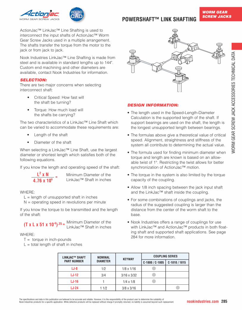
ActionJac™ LinkJac™ Line Shafting is used to interconnect the input shafts of ActionJac™ Worm Gear Screw Jacks used in a multiple arrangement. The shafts transfer the torque from the motor to the jack or from jack to jack.
Nook Industries LinkJac™ Line Shafting is made fromsteel and is available in standard lengths up to 144".Custom end machining and other diameters are available, contact Nook Industries for information.
SELECTION:There are two major concerns when selecting interconnect shaft:
• Critical Speed: How fast will the shaft be turning?
• Torque: How much load will the shafts be carrying?
The two characteristics of a LinkJac™ Line Shaft whichcan be varied to accommodate these requirements are:
• Length of the shaft
• Diameter of the shaft
When selecting a LinkJac™ Line Shaft, use the largestdiameter or shortest length which satisfies both of thefollowing equations.
If you know the length and operating speed of the shaft:
L2 x N = Minimum Diameter of the
4.76 x 10⁶ LinkJac™ Shaft in inches
WHERE: L = length of unsupported shaft in inchesN = operating speed in revolutions per minute
If you know the torque to be transmitted and the lengthof the shaft:
(T x L x 51 x 10-6).25 = Minimum Diameter of the LinkJac™ Shaft in inches
WHERE:T = torque in inch-poundsL = total length of shaft in inches
DESIGN INFORMATION:
• The length used in the Speed-Length-DiameterCalculation is the supported length of the shaft. Ifsupport bearings are used on the shaft, the length isthe longest unsupported length between bearings.
• The formulas above give a theoretical value of criticalspeed. Alignment, straightness and stiffness of thesystem all contribute to determining the actual value.
• The formula used for finding minimum diameter whentorque and length are known is based on an allow-able twist of 1°. Restricting the twist allows for bettersynchronization of ActionJac™ motion.
• The torque in the system is also limited by the torquecapacity of the coupling.
• Allow 1/8 inch spacing between the jack input shaftand the LinkJac™ shaft inside the coupling.
• For some combinations of couplings and jacks, theradius of the suggested coupling is larger than thedistance from the center of the worm shaft to thebase.
• Nook Industries offers a range of couplings for usewith LinkJac™ and ActionJac™ products in both float-ing shaft and supported shaft applications. See page284 for more information.
1/2
3/4
1
1 1/2
1/8 x 1/16
3/16 x 3/32
1/4 x 1/8
3/8 x 3/16
LJ-8
LJ-12
LJ-16
LJ-24
WORM GEARSCREW JACKS
WOR
M G
EAR
SCRE
W J
ACK
ACCE
SSOR
IES
TECH
NICA
L DA
TA
nookindustries.com286The specifications and data in this publication are believed to be accurate and reliable. However, it is the responsibility of the product user to determine the suitability of
Nook Industries products for a specific application. While defective products will be replaced without charge if promptly returned, no liability is assumed beyond such replacement.
WORM GEAR SCREW JACKS
2D/3DCAD2D/3DCADSTANDARD MITER GEAR ASSEMBLIES
GEAR RATIO 1:1
7
83141
43
43
8
1611
72
163 KEYWAY
TYP.43
- 18 TAPPED MOUNTING HOLES(8)16
5
16154
853
16131
16131
1693
16114
PIPE PLUG (2)
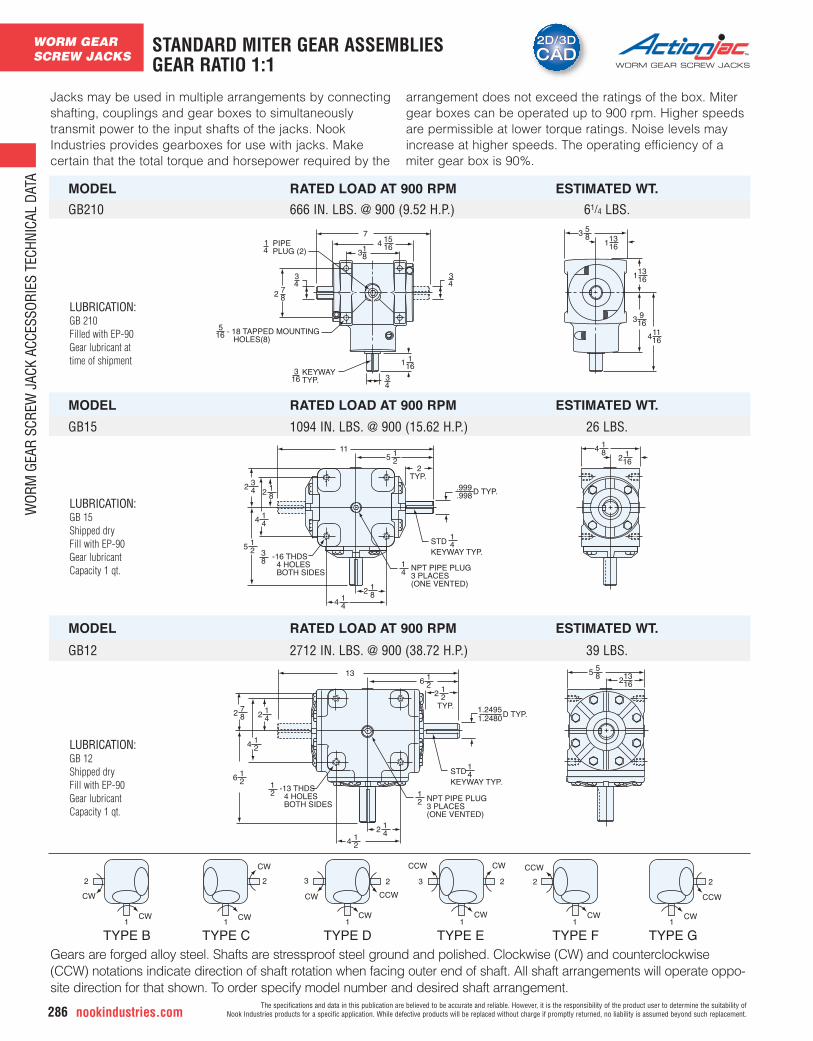
Jacks may be used in multiple arrangements by connectingshafting, couplings and gear boxes to simultaneouslytransmit power to the input shafts of the jacks. NookIndustries provides gearboxes for use with jacks. Makecertain that the total torque and horsepower required by the
arrangement does not exceed the ratings of the box. Mitergear boxes can be operated up to 900 rpm. Higher speedsare permissible at lower torque ratings. Noise levels mayincrease at higher speeds. The operating efficiency of amiter gear box is 90%.
1.2480
13
872
412
214
216
216
212
412
214
21 NPT PIPE PLUG
3 PLACES(ONE VENTED)
STD KEYWAY TYP.
41
TYP.D TYP.
1.2495
21 -13 THDS
4 HOLES BOTH SIDES
855
16132
CW
2
1CW
TYPE B
2
1CW
TYPE C
CW
TYPE D
CW
CW CCW
2
1
3
TYPE E
CCW CW
CW
TYPE F TYPE G
CCW
CCW
CWCW
2
1
3 2
1
2
1
215
11
432
812
414
215
812
414
418
3 -16 THDS 4 HOLES BOTH SIDES
STD KEYWAY TYP.
41
NPT PIPE PLUG3 PLACES(ONE VENTED)
2TYP.
.999
.998D TYP.
1612
814
MODEL RATED LOAD AT 900 RPM ESTIMATED WT.
GB210 666 IN. LBS. @ 900 (9.52 H.P.) 61/4 LBS.
GB15 1094 IN. LBS. @ 900 (15.62 H.P.) 26 LBS.
GB12 2712 IN. LBS. @ 900 (38.72 H.P.) 39 LBS.
MODEL RATED LOAD AT 900 RPM ESTIMATED WT.
MODEL RATED LOAD AT 900 RPM ESTIMATED WT.
Gears are forged alloy steel. Shafts are stressproof steel ground and polished. Clockwise (CW) and counterclockwise(CCW) notations indicate direction of shaft rotation when facing outer end of shaft. All shaft arrangements will operate oppo-site direction for that shown. To order specify model number and desired shaft arrangement.
LUBRICATION:GB 210Filled with EP-90Gear lubricant attime of shipment
LUBRICATION:GB 15Shipped dryFill with EP-90Gear lubricantCapacity 1 qt.
LUBRICATION:GB 12Shipped dryFill with EP-90Gear lubricantCapacity 1 qt.
WORM GEARSCREW JACKS
The specifications and data in this publication are believed to be accurate and reliable. However, it is the responsibility of the product user to determine the suitability of Nook Industries products for a specific application. While defective products will be replaced without charge if promptly returned, no liability is assumed beyond such replacement. nookindustries.com 287
2D/3DCAD2D/3DCAD
WORM GEAR SCREW JACKS
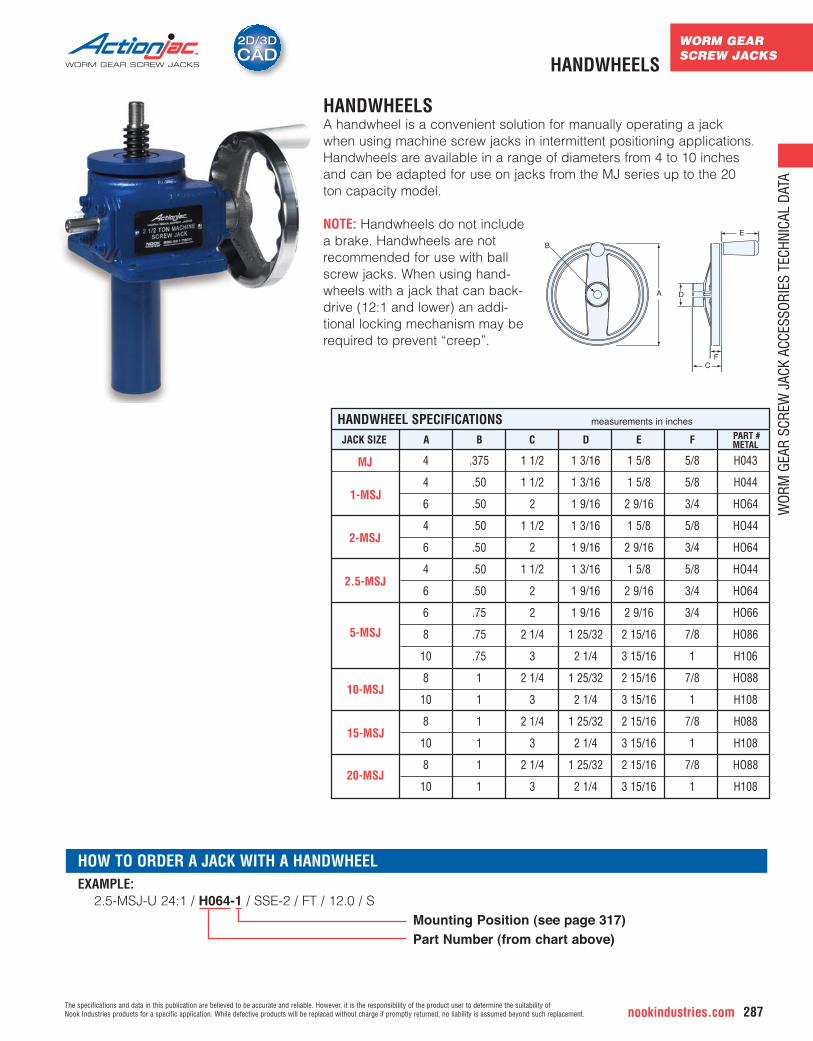
HANDWHEELSA handwheel is a convenient solution for manually operating a jack when using machine screw jacks in intermittent positioning applications.Handwheels are available in a range of diameters from 4 to 10 inchesand can be adapted for use on jacks from the MJ series up to the 20 ton capacity model.
NOTE: Handwheels do not includea brake. Handwheels are not recommended for use with ballscrew jacks. When using hand-wheels with a jack that can back-drive (12:1 and lower) an addi-tional locking mechanism may berequired to prevent “creep”.
HANDWHEELS
JACK SIZE A B C D E PART #F
HANDWHEEL SPECIFICATIONS
METAL
A
E
D
CF
B
4
4
6
4
6
4
6
6
8
10
8
10
8
10
8
10
.375
.50
.50
.50
.50
.50
.50
.75
.75
.75
1
1
1
1
1
1
1 1/2
1 1/2
2
1 1/2
2
1 1/2
2
2
2 1/4
3
2 1/4
3
2 1/4
3
2 1/4
3
1 3/16
1 3/16
1 9/16
1 3/16
1 9/16
1 3/16
1 9/16
1 9/16
1 25/32
2 1/4
1 25/32
2 1/4
1 25/32
2 1/4
1 25/32
2 1/4
1 5/8
1 5/8
2 9/16
1 5/8
2 9/16
1 5/8
2 9/16
2 9/16
2 15/16
3 15/16
2 15/16
3 15/16
2 15/16
3 15/16
2 15/16
3 15/16
5/8
5/8
3/4
5/8
3/4
5/8
3/4
3/4
7/8
1
7/8
1
7/8
1
7/8
1
H043
H044
HO64
HO44
HO64
HO44
HO64
HO66
HO86
H106
HO88
H108
H088
H108
HO88
H108
measurements in inches
MJ
1-MSJ
2-MSJ
2.5-MSJ
5-MSJ
10-MSJ
15-MSJ
20-MSJ
EXAMPLE: 2.5-MSJ-U 24:1 / H064-1 / SSE-2 / FT / 12.0 / S
Mounting Position (see page 317)Part Number (from chart above)
HOW TO ORDER A JACK WITH A HANDWHEEL
WOR
M G
EAR
SCRE
W J
ACK
ACCE
SSOR
IES
TECH
NICA
L DA
TA
WORM GEARSCREW JACKS
WOR
M G
EAR
SCRE
W J
ACK
ACCE
SSOR
IES
TECH
NICA
L DA
TA
nookindustries.com288The specifications and data in this publication are believed to be accurate and reliable. However, it is the responsibility of the product user to determine the suitability of
Nook Industries products for a specific application. While defective products will be replaced without charge if promptly returned, no liability is assumed beyond such replacement.
WORM GEAR SCREW JACKS
2D/3DCAD2D/3DCADCOUNTERS
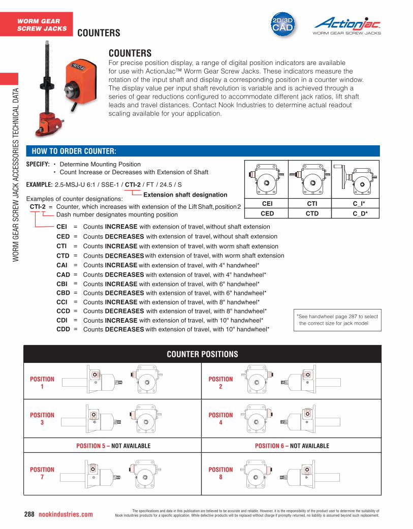
COUNTERSFor precise position display, a range of digital position indicators are available for use with ActionJac™ Worm Gear Screw Jacks. These indicators measure therotation of the input shaft and display a corresponding position in a counter window.The display value per input shaft revolution is variable and is achieved through aseries of gear reductions configured to accommodate different jack ratios, lift shaftleads and travel distances. Contact Nook Industries to determine actual readoutscaling available for your application.
CEI CTI
CED CTD
SPECIFY: • Determine Mounting Position• Count Increase or Decreases with Extension of Shaft
EXAMPLE: 2.5-MSJ-U 6:1 / SSE-1 / CTI-2 / FT / 24.5 / S Extension shaft designation
Examples of counter designations: CTI-2 = Counter, which increases with extension of the Lift Shaft, position 2
Dash number designates mounting position
CEI = Counts INCREASE with extension of travel, without shaft extension
CED = Counts DECREASES
CTI = Counts INCREASE with worm shaft extension
CTD = Counts DECREASES
HOW TO ORDER COUNTER:
C_I*
C_D*
CAI = Counts INCREASE with extension of travel, with 4" handwheel*
CAD = Counts DECREASES with extension of travel, with 4" handwheel*
CBI = Counts INCREASE with extension of travel, with 6" handwheel*CBD = Counts DECREASES with extension of travel, with 6" handwheel*
CCI = Counts INCREASE with extension of travel, with 8" handwheel*CCD = Counts DECREASES with extension of travel, with 8" handwheel*
CDI = Counts INCREASE with extension of travel, with 10" handwheel*CDD = Counts DECREASES with extension of travel, with 10" handwheel*
with extension of travel, without shaft extension
with extension of travel,
with worm shaft extensionwith extension of travel,
COUNTER POSITIONS
POSITION1
POSITION3
POSITION7
POSITION2
POSITION4
POSITION8
POSITION 5 – NOT AVAILABLE POSITION 6 – NOT AVAILABLE
*See handwheel page 287 to select the correct size for jack model
WORM GEARSCREW JACKS
WOR
M G
EAR
SCRE
W J
ACK
ACCE
SSOR
IES
TECH
NICA
L DA
TA
The specifications and data in this publication are believed to be accurate and reliable. However, it is the responsibility of the product user to determine the suitability of Nook Industries products for a specific application. While defective products will be replaced without charge if promptly returned, no liability is assumed beyond such replacement. nookindustries.com 289
WORM GEAR SCREW JACKS
C
C C
NCLOSED
M+ TRAVEL
NCLOSED
M+ TRAVEL
NCLOSED
M+ TRAVEL
M+ TRAVEL
M+ TRAVEL
N
NL
K
K
J
JL
C
K
J
L
L
CN
CLOSED
M + TRAVEL
K
J
L
P
PJ
K
K
L
JC
A
H
BF
Ø D PIN
E - MAXPIN DEPTH
F
G
BSJ and MSJ Trunnion Bottom View BSJ-U (Ball Screw Upright)
BSJ-I(Ball Screw Inverted)
MSJ-U(Machine Screw Upright)
MSJ-I(Machine Screw Inverted)
BSJ-UR and MSJ-UR(Ball and Machine Screw Upright Rotating)
BSJ-IR and MSJ-IR(Ball and Machine Screw Inverted Rotating)
COMMON DIMENSIONS FOR U, I , UR & IR UPRIGHT
M N
INVERTED UPRIGHT ROTATING INVERTED ROTATING
PA B C D E F G H L KJ M NK M NK PM NK
JACK MODELTRUNNION
PART #
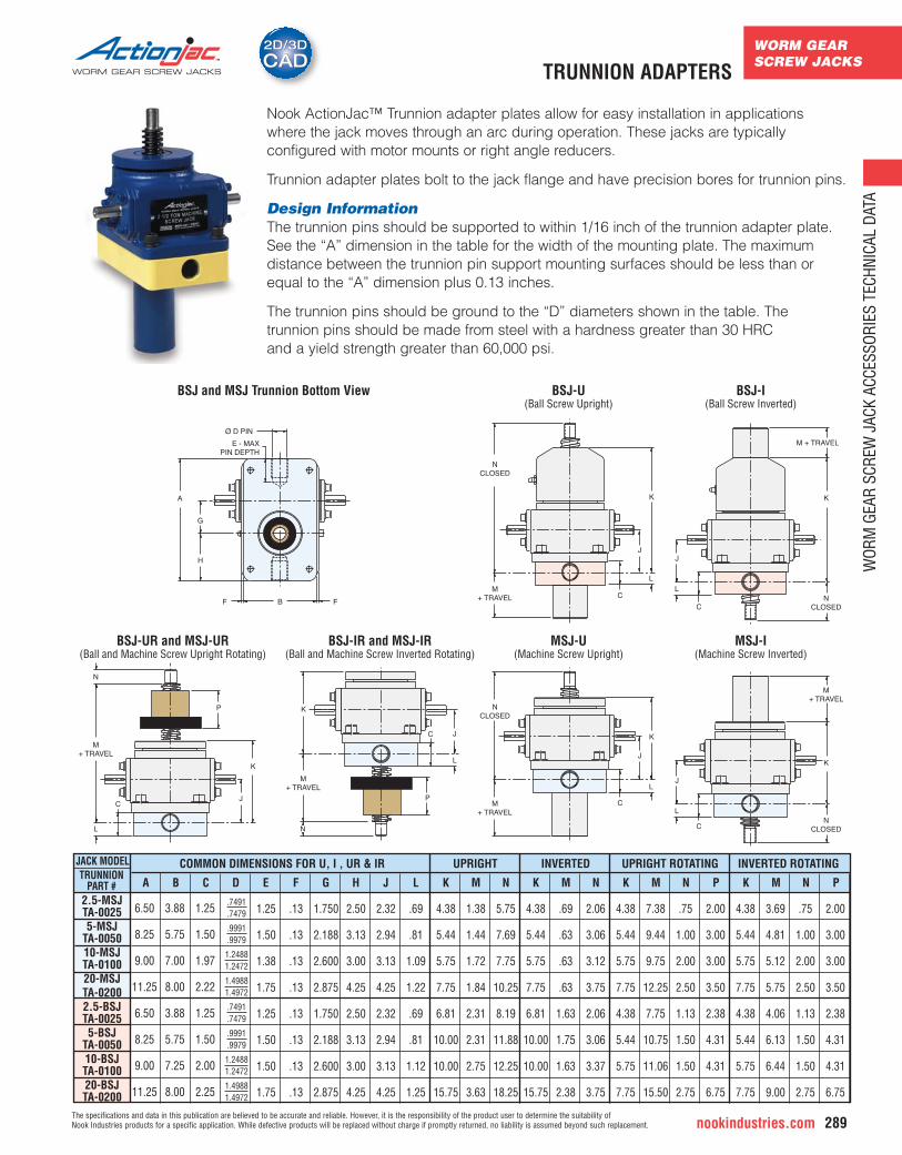
Nook ActionJac™ Trunnion adapter plates allow for easy installation in applications where the jack moves through an arc during operation. These jacks are typically configured with motor mounts or right angle reducers.
Trunnion adapter plates bolt to the jack flange and have precision bores for trunnion pins.
Design InformationThe trunnion pins should be supported to within 1/16 inch of the trunnion adapter plate.See the “A” dimension in the table for the width of the mounting plate. The maximum distance between the trunnion pin support mounting surfaces should be less than orequal to the “A” dimension plus 0.13 inches.
The trunnion pins should be ground to the “D” diameters shown in the table. The trunnion pins should be made from steel with a hardness greater than 30 HRC and a yield strength greater than 60,000 psi.
6.50
8.25
9.00
11.25
6.50
8.25
9.00
11.25
3.88
5.75
7.00
8.00
3.88
5.75
7.25
8.00
1.25
1.50
1.97
2.22
1.25
1.50
2.00
2.25
1.25
1.50
1.38
1.75
1.25
1.50
1.50
1.75
.13
.13
.13
.13
.13
.13
.13
.13
1.750
2.188
2.600
2.875
1.750
2.188
2.600
2.875
2.50
3.13
3.00
4.25
2.50
3.13
3.00
4.25
2.32
2.94
3.13
4.25
2.32
2.94
3.13
4.25
.69
.81
1.09
1.22
.69
.81
1.12
1.25
4.38
5.44
5.75
7.75
6.81
10.00
10.00
15.75
1.38
1.44
1.72
1.84
2.31
2.31
2.75
3.63
5.75
7.69
7.75
10.25
8.19
11.88
12.25
18.25
4.38
5.44
5.75
7.75
6.81
10.00
10.00
15.75
.69
.63
.63
.63
1.63
1.75
1.63
2.38
2.06
3.06
3.12
3.75
2.06
3.06
3.37
3.75
4.38
5.44
5.75
7.75
4.38
5.44
5.75
7.75
7.38
9.44
9.75
12.25
7.75
10.75
11.06
15.50
.75
1.00
2.00
2.50
1.13
1.50
1.50
2.75
2.00
3.00
3.00
3.50
2.38
4.31
4.31
6.75
4.38
5.44
5.75
7.75
4.38
5.44
5.75
7.75
3.69
4.81
5.12
5.75
4.06
6.13
6.44
9.00
.75
1.00
2.00
2.50
1.13
1.50
1.50
2.75
2.00
3.00
3.00
3.50
2.38
4.31
4.31
6.75
2.5-MSJTA-00255-MSJ
TA-005010-MSJTA-010020-MSJTA-02002.5-BSJTA-00255-BSJ
TA-005010-BSJTA-010020-BSJTA-0200
.7491
.7479
.9991
.9979
1.24881.2472
1.49881.4972
.7491
.7479
.9991
.9979
1.24881.2472
1.49881.4972
TRUNNION ADAPTERS
INCH BALLSCREW JACKS
INCH
BAL
L SC
REW
JAC
KS T
ECHN
ICAL
DAT
A
nookindustries.com290The specifications and data in this publication are believed to be accurate and reliable. However, it is the responsibility of the product user to determine the suitability of
Nook Industries products for a specific application. While defective products will be replaced without charge if promptly returned, no liability is assumed beyond such replacement.
WORM GEAR SCREW JACKS
2D/3DCAD2D/3DCAD
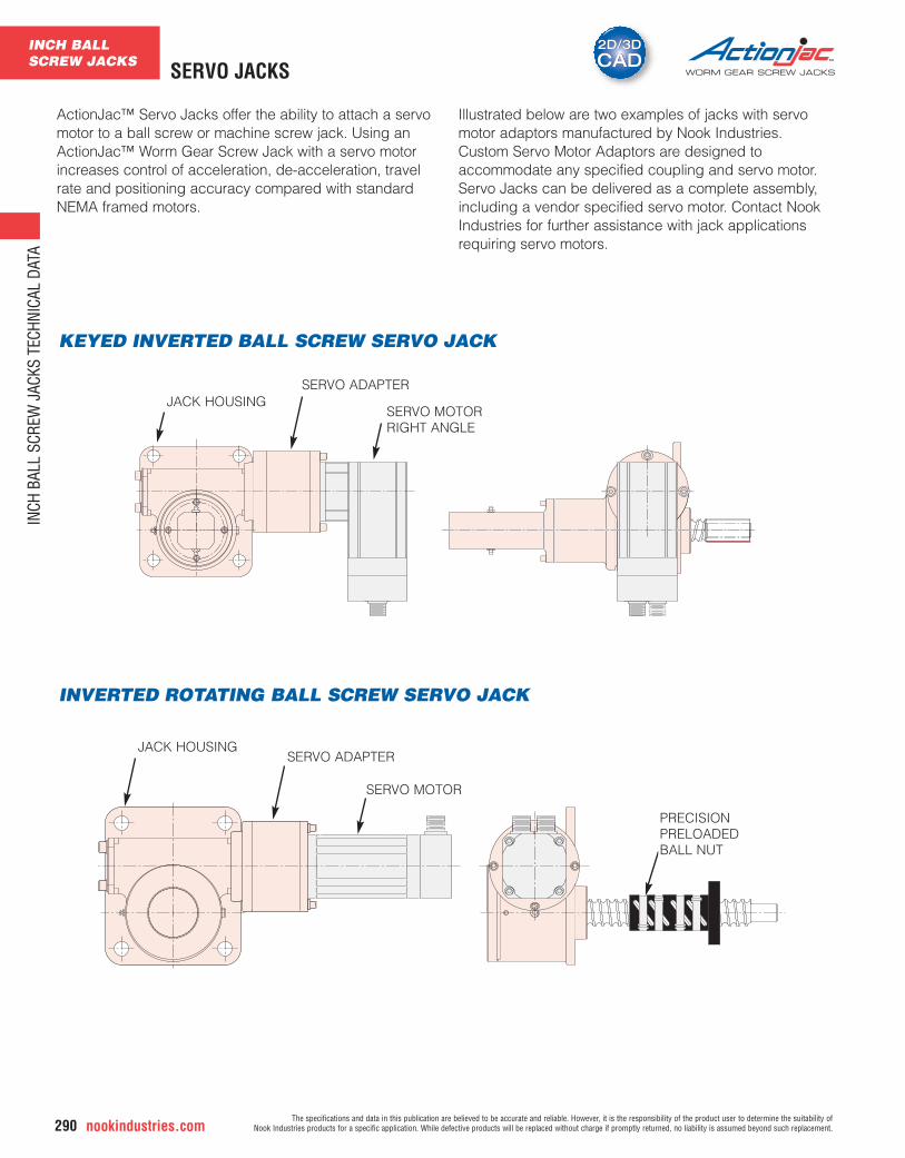
ActionJac™ Servo Jacks offer the ability to attach a servomotor to a ball screw or machine screw jack. Using anActionJac™ Worm Gear Screw Jack with a servo motorincreases control of acceleration, de-acceleration, travelrate and positioning accuracy compared with standardNEMA framed motors.
Illustrated below are two examples of jacks with servomotor adaptors manufactured by Nook Industries.Custom Servo Motor Adaptors are designed to accommodate any specified coupling and servo motor.Servo Jacks can be delivered as a complete assembly,including a vendor specified servo motor. Contact NookIndustries for further assistance with jack applicationsrequiring servo motors.
INVERTED ROTATING BALL SCREW SERVO JACK
KEYED INVERTED BALL SCREW SERVO JACK
SERVO MOTOR
SERVO MOTORRIGHT ANGLE
JACK HOUSINGSERVO ADAPTER
JACK HOUSINGSERVO ADAPTER
PRECISION PRELOADED BALL NUT
SERVO JACKS
Related Documents