1 Nonlinear Finite Element Analysis of Space Truss Dr. Ahmed Farhan Kadhum Lecturer University of Technology-Building and Construction Engineering Department E-mail: [email protected] Abstract: This paper presents analytical investigation included the use of three dimensional nonlinear finite elements to model the performance of the space trusses by using (ANSYS 11.0) computer program. The numerical results show very good agreement (100%) with experimental results, while the graphical option reflects the behavior of the structure under the applied loads because the ability of this option to simulate the real behavior of the structure under these loads. Also finite element models of the space truss simulate the lateral deflection of the top chord members especially at the corners, and the twisting of the bottom chords. Keywords: Space Truss, Top Chord, Bottom Chord, Finite Element, ANSYS 11.0, Shell Element. خطي اليلتحل اللفضائيةت المسنماصر المحددة للعناستخدام ا باصة الخ: سيتخدامس باالءضيا اياد يبعي ثيسنم ثتمثيل مبعاد لثية اصر المحددة ثلعنان استخدام ا اسة تحليلية تتضم يقدم هذا البحث در ي( برنيامANSYS 11.0 يرتحليلي ة ا ال( اي النتي حي ث انلحاسيبة ث ا س عليايدا ديد تطيابج د ت بة ي و بنسي111 س% ( اي النتي ميامسيلطة الحميال سثير ا تيحيتلمنايس ت ا تصير عحيت(لبرنيام هيذا اي ر الرسيمن خيا ين ا حيي عمليةف اللخي ار ة هيذا اابليق ب بسيبحميال احيت هيذلمايس ت لقي الحقي التصيرتمثي ل لبعياد مثي ة ات الثلمسينماصير المحيددة للعنا ا نميوذايان . حيذلف لتايو ثليت اسيءلا الوترية الاعضياا للتيوا و ايا واصية عنيد الوعلي ا خا الوترية الاعضيا للديانب ا حيل مين ي يوهاتحبير تا ف حميا حانيتلمحاور ي اx, y , y نوع يمءصلفد منلمسان عند ا س تقاhinge سنم يلم بالنسبة ل سA سنم يلمما بانسبة ل سB يوهاتحبير تا حانيت سلمساند عند ا تقا نوع يبحرةف منroller س. Introduction: Space truss are popular in covering large open areas with few or no internal supports. Among their advantages are mass production, easy transportation, fast assembly, light weight and pleasant appearance. The last four decades have been a widespread use of space trusses and the development of many new systems, each with different features to attract users and gain a larger share in large- span structures markets [Ahmed El-Sheikh, 1996]. Space truss systems can generally be put into two main groups: 1) Systems with short chord members joined together by node connectors;

Welcome message from author
This document is posted to help you gain knowledge. Please leave a comment to let me know what you think about it! Share it to your friends and learn new things together.
Transcript
1
Nonlinear Finite Element Analysis of Space Truss
Dr. Ahmed Farhan Kadhum
Lecturer
University of Technology-Building and Construction Engineering Department
E-mail: [email protected]
Abstract:
This paper presents analytical investigation included the use of three dimensional nonlinear finite
elements to model the performance of the space trusses by using (ANSYS 11.0) computer program.
The numerical results show very good agreement (100%) with experimental results, while the
graphical option reflects the behavior of the structure under the applied loads because the ability of
this option to simulate the real behavior of the structure under these loads. Also finite element
models of the space truss simulate the lateral deflection of the top chord members especially at the
corners, and the twisting of the bottom chords.
Keywords:
Space Truss, Top Chord, Bottom Chord, Finite Element, ANSYS 11.0, Shell Element.
باستخدام العناصر المحددة للمسنمات الفضائية التحليل الالخطي
:الخالصة
يقدم هذا البحث دراسة تحليلية تتضمن استخدام العناصر المحددة ثالثية األبعاد لتمثيل مسنم ثالثي ألألبعياد ي ي الءضيااس باسيتخدام مييا النتيياي) %س111و بنسييبة ي ت تطييابج ديييد دييداس علييا الحاسييبة ث حيييث ان النتيياي) التحليلييية ا يير ANSYS 11.0برنييام) ي
بسييبق بابلييية هييذا الخيييار العمليييةف يي حييين ان خيييار الرسييم يي هييذا البرنييام) عحييت تصييرأل المناييس تحييت تييسثير األحمييال المسييلطةثلييت التاييو . حييذلف ييان نمييوذا العناصيير المحييددة للمسيينمات الثالثييية األبعيياد ملتمثيييل التصييرأل الحقيقيي للماييس تحييت هييذ ا حمييال
ف حمييا حانييت ألحبيير تاييوهات يي حييل ميين الدييانب لالعضيياا الوترييية العليييا خاصيية عنييد الووايييا و األلتييواا لالعضيياا الوترييية السييءلاس حانيت ألحبير تايوهات Bس ألما بانسبة للمسنم يAس بالنسبة للمسنم يhingeس تقا عند المساند من نوع يمءصلف x, y , yالمحاور ي
.سrollerمن نوع يبحرةف تقا عند المساند
Introduction:
Space truss are popular in covering large open areas with few or no internal supports. Among their
advantages are mass production, easy transportation, fast assembly, light weight and pleasant
appearance. The last four decades have been a widespread use of space trusses and the development
of many new systems, each with different features to attract users and gain a larger share in large-
span structures markets [Ahmed El-Sheikh, 1996].
Space truss systems can generally be put into two main groups:
1) Systems with short chord members joined together by node connectors;
2
most space trusses available today belong to this group of systems. They generally consist of
similar members of short length connected at the joints with similar nodes (that are usually
sophisticated and expensive); and
2) Systems with continuous chord members that do not need nodes for their assembly;
in order to overcome the high cost normally associated with space trusses, system have been
developed with jointing methods that do not rely on special node connectors. In order to achieve
that the chord members of this group of trusses are made continuous across the joints and
usually are connected directly together, either by bolting or welding.
A conclusions concerning optimum design of double-layer space grids were submitted by
[Henning Agerskov, 1986] made from the results obtained in the investigation. The member density
must be small. In addition to giving a small material consumption, this leads to a grid with
relatively few nodal points and thus least possible production costs for nodes, erection expenses etc.
The results presented by [Erling Murtha-Smith, 1988]of the analysis prformed on a hypothetical
space truss and on a constructed space truss show that progressive collapse could occur following
the loss of one of several potentially critical members when the structures are subjected to full
service loading. However, when the structures were evaluated using the American National
Standard ANSI A58.1-1982, the structures were found to survive with a small margin safety. It is
suggested that to improve resistance to progressive collapse the compression members and
additional members along and adjacent to the column line should be designed with higher factors of
safety than those currently used, particularly in the middle half of the span.
A methodology was developed by [Christopher D. Hill, Goerge E. Blandford, and Shein T.
Wang, 1989] to perform nonlinear postbuckling analysis of steel space truss systems. Structural
behavior is modeled at the element level through appropriate stress-strain relationships.
Nonlinearities due to member buckling or yielding are modeled using a tangent modulus in the
evaluation of the element stiffness matrix. Results are obtained and compared for linear and
nonlinear material behavior along with second-order geometric nonlinearity. The general results
provide information on the failure mechanisms most critical to a particular truss system, and
techniques which can be used to reduce the effects of the failure mechanisms are described.
Another new space truss system, named Catrus, had been developed at the University of
Dundee by [Ahmed El-Sheikh, 1996]. The target has been to design a system that combines low
cost with reliable structural behavior, and provide solutions for many practical applications. The
main feature of Catrus is the top and bottom chord members are continuous across the joints, the
members are directly bolted together without any node connectors, and chord and diagonal
members are stacked above each other.
Another paper presented by [A. I. El-Sheikh, and H. El-Bakry, 1996] a space truss system newly
developed with the main objective of achieving a larger reduction in the overall cost of space truss
without compromise in the structural reliability or the common case of construction. To achieve this
goal, the new truss has a simple joining system that requires no expensive node connectors, and a
simple member splicing system that has almost no adverse effect on the truss's performance. The
paper includes an introduction to the system's feature and an experimental assessment of the claim
that the new joining system of the truss does not entail any compromise in its structural efficiency
or reliability.
A paper presented about the space truss by Ömer Kelesoglu and Mehmet ükler [Ömer and
Mehmet, 2005] with a general algorithm for nonlinear space truss system optimization with fuzzy
constraints and fuzzy parameters. The analysis of the space truss system is performed with the
ANSYS program. The algorithm multiobjective fuzzy technique was formed with ANSYS
parametric dimensional language. In the formulation of the design problem, weight and minimum
displacement are considered the objective functions. Three design examples are presented to
demonstrate the application of the algorithm.
[Jin-Woo Kim, Jeung-Hwan Doh, and Yong-Hee Lee, 2008] presented a paper discuss the
behavior of cable-tensioned and shaped hyper space truss, with consideration of the influence of
removing some web members in two directions. Hyper shaped space truss is cable-tensioned at the
3
strand of bottom chords with one diagonal on the ground; the essential behavior characteristic of
shape formation is discussed by using a small-scale test model. Results of experiments and
nonlinear finite-element analysis indicate that a planar, rectangular-arranged structure can be
deformed to a predicated hyper shape, by the proposed cable-tensioning method. Also the feasibility
of the proposed method for furnishing of a hyper shaped space truss has been presented, under the
conditions removed web members with both active diagonal and passive diagonal.
Parametric Study:
Verification is done in order to check the validity and accuracy of the finite element procedure.
Thus, two space trusses (A and B) with available experimental results [Ahmed El-Sheikh, 1996]
have been analyzed here and the analytical results are compared.
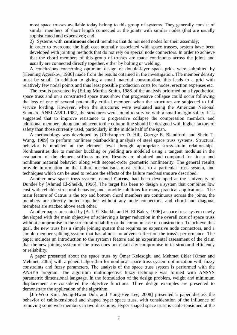
The space truss Catrus is consisted from:
Top chord members: rectangular hollow sections (RHS) are used in the top chord members of
Catrus to resist their dominantly compression forces.
Bottom chord members: the bottom chord members of Catrus are flat strips prepared. The use
of flat strips provides a number of advantages including simple fabrication, simple splicing, and
low tendency for joint rotation.
Diagonal members: the diagonal members of Catrus are made of circular hollow section (CHS)
tubes with their ends squashed as shown in Fig. 1.
The space trusses of the experimental work are:
1. Truss A with overdesigned top chord members (by 30%). This truss modeled a practical
situation in which the top members were moderately overdesigned to bring in some ductile
behavior.
2. Truss B with underdesigned top chord members (by 40%). This truss modeled an impractical
case and was only included to study the efficiency of Catrus trusses in accommodating cases of
individual member buckling.
Fig. 1 Layout of test trusses [Ahmed El-Sheikh, 1996]
(

4
Finite Element:
The space trusses A and B were analyzed with (ANSYS software computer program release 11.0)
idealized by subdividing the structure into a number of elements as shown in Fig. 2.
Fig. 2 ANSYS mesh of space truss A
1. Top and Bottom Chord Members were modeled by Shell-143 element is well suited for
to model nonlinear , flat or wrapped, thin to moderately–thick shell structures. The element
has six degrees of freedom at each node: translations in the nodal x, y, and z-directions and
rotations about the nodal x, y, and z-axis. The deformation shapes are linear in both in-plane
directions. For the out-of-plane motion, it uses a mixed interpolation of tensional
components. The element has plasticity, creep, stress stiffening, large deflection, and small
strain capacities. The geometry, node locations, and the coordinate system for this element
are shown in Fig. 3.
Fig. 3 Shell (143) geometry [ANSYS, 2007]
Top Chord Members
Bottom Chord Members
Diagonal Members
Support
Applied Loads
See Figure (5)
5
The element is defined by four nodes, four thicknesses, and the orthotropic material
properties. A triangular-shaped element may be formed by defining the same node number
for nodes K and L as described in triangle. Orthotropic material directions correspond to the
element coordinate directions [ANSYS, 2007].
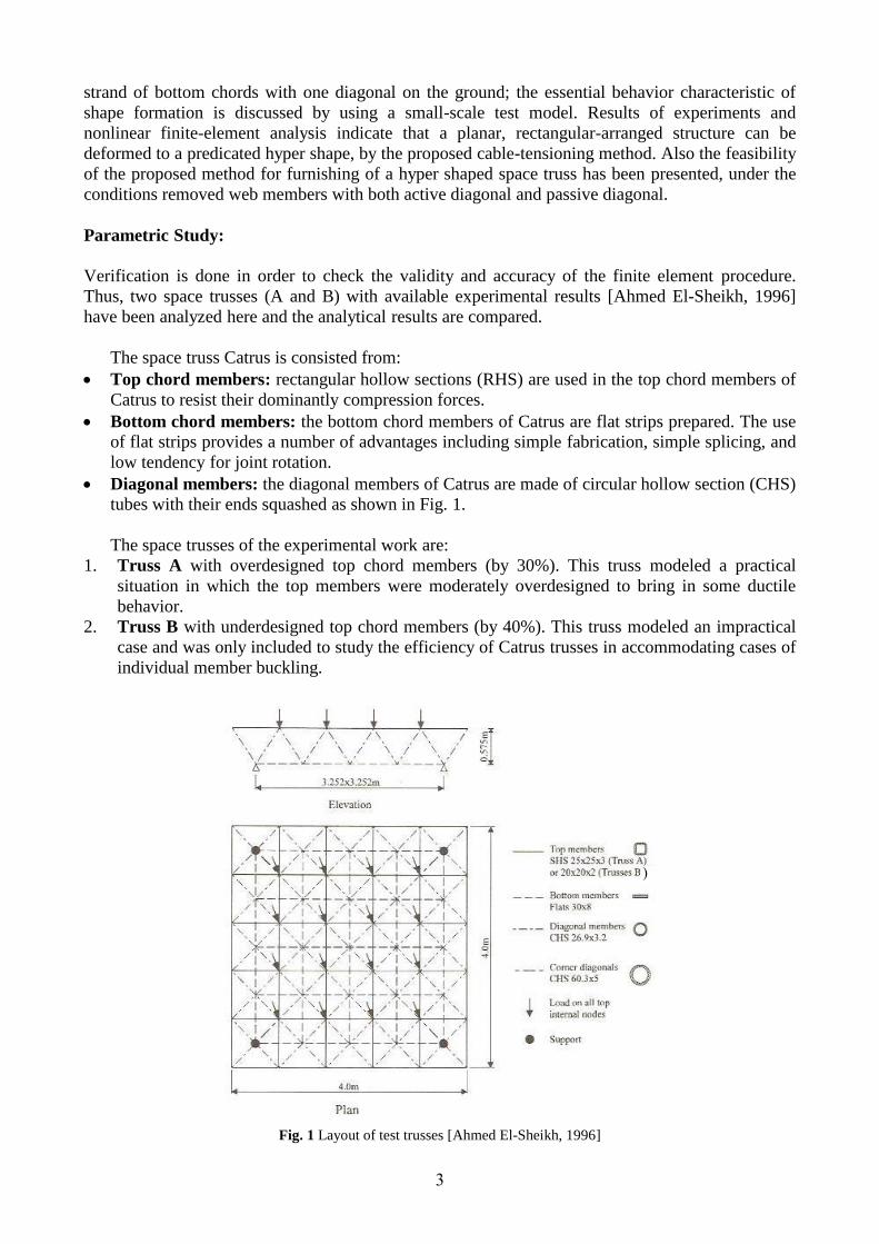
2. Diagonal Members were modeled by Link-180 is a spar that can be used in a variety of
engineering applications. This element can be used to model truss, sagging cables, links,
springs, etc. This 3-D spar element is a uniaxial tension-compression element with three
degrees of freedom at each node: translation in the nodal x,y, and z directions. As a pin-
jointed structure, no bending of the element is considered. Plasticity, creep, rotation, large
deflection, and large strain capabilities. Elasticity, isotropic hardening plasticity, kinematic
hardening plasticity and creep are supported. The geometry, node locations, and the
coordinate system for this element are shown in Fig. 4. Also link-180 allows a change in
cross-sectional area as a function of axial elongation. By default, the cross-sectional area
changes such that the volume of the element is preserved, even after deformation. The
default is suitable for elastoplastic applications.
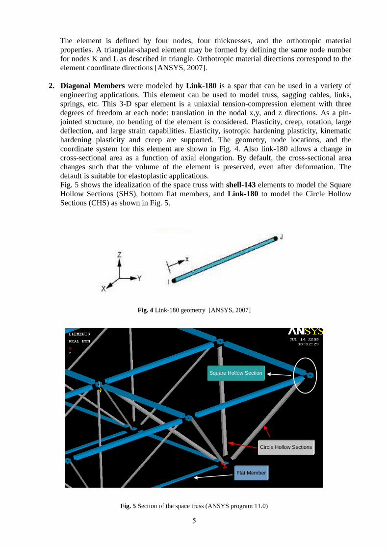
Fig. 5 shows the idealization of the space truss with shell-143 elements to model the Square
Hollow Sections (SHS), bottom flat members, and Link-180 to model the Circle Hollow
Sections (CHS) as shown in Fig. 5.
Fig. 4 Link-180 geometry [ANSYS, 2007]
Fig. 5 Section of the space truss (ANSYS program 11.0)
Square Hollow Section
Circle Hollow Sections
Flat Member
6
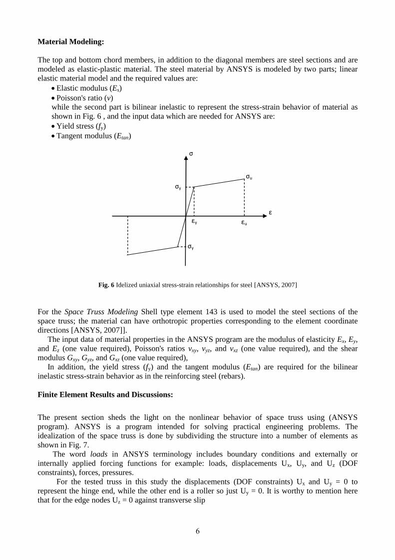
Material Modeling:
The top and bottom chord members, in addition to the diagonal members are steel sections and are
modeled as elastic-plastic material. The steel material by ANSYS is modeled by two parts; linear
elastic material model and the required values are:
Elastic modulus (Es)
Poisson's ratio (v)
while the second part is bilinear inelastic to represent the stress-strain behavior of material as
shown in Fig. 6 , and the input data which are needed for ANSYS are:
Yield stress (fy)
Tangent modulus (Etan)
Fig. 6 Idelized uniaxial stress-strain relationships for steel [ANSYS, 2007]
For the Space Truss Modeling Shell type element 143 is used to model the steel sections of the
space truss; the material can have orthotropic properties corresponding to the element coordinate
directions [ANSYS, 2007]].
The input data of material properties in the ANSYS program are the modulus of elasticity Ex, Ey,
and Ez (one value required), Poisson's ratios vxy, vyz, and vxz (one value required), and the shear
modulus Gxy, Gyz, and Gxz (one value required),
In addition, the yield stress (fy) and the tangent modulus (Etan) are required for the bilinear
inelastic stress-strain behavior as in the reinforcing steel (rebars).
Finite Element Results and Discussions:
The present section sheds the light on the nonlinear behavior of space truss using (ANSYS
program). ANSYS is a program intended for solving practical engineering problems. The
idealization of the space truss is done by subdividing the structure into a number of elements as
shown in Fig. 7.
The word loads in ANSYS terminology includes boundary conditions and externally or
internally applied forcing functions for example: loads, displacements Ux, Uy, and Uz (DOF
constraints), forces, pressures.
For the tested truss in this study the displacements (DOF constraints) Ux and Uy = 0 to
represent the hinge end, while the other end is a roller so just Uy = 0. It is worthy to mention here
that for the edge nodes Uz = 0 against transverse slip
σy
σy
σu
εu εy
σ
ε

7
(a) Side view of the space truss (ANSYS program 11.0)
(a) Top view of the space truss (ANSYS program 11.0)
Fig. 7 Space truss mesh by ANSYS program release 11.0
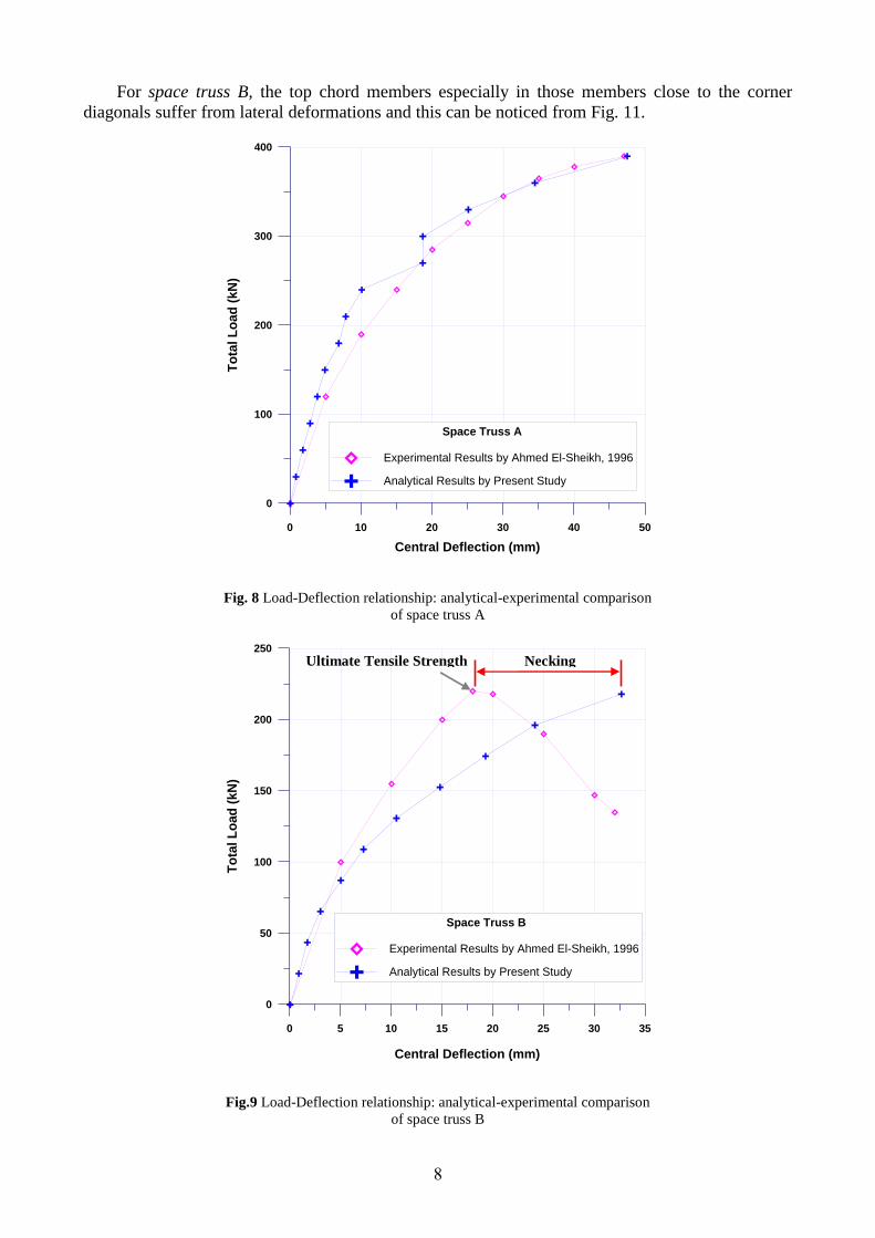
From the load-deflection curves of the two space trusses A and B analyzed by finite element
ANSYS program plotted by GRAPHER 1.09 software as shown in Figs. (8 and 9) and compared
with the experimental results by [Ahmed El-Sheikh, 1996]. It can be seen very good agreement
between the experimental and analytical values and as summarized in table 1, while there is a
difference between the experimental and theoretical curves path and this obvious in Fig. 9 and the
reason for this manner that the analysis modeling used in this study could not catch the part of steel
material behavior which is known as "necking" phenomena, which can be defined as: (after a
critical value y of the stress has been reached, the specimen undergoes a large deformation with a
relatively small increase in the applied load. This deformation is caused by slippage of the material
along oblique surfaces. After a certain maximum values of the load has been reached, the diameter
of a portion of the specimen begins to decrease, because of local instability) [Beer F., Jr E. Russell,
and DeWolf J., 2006] in addition to the mentioned before, after this certain maximum load which is
known as UTS (Ultimate Tensile Strength) (denoted σ f in these modulus). (Beyond that point, the
material appears to strain soften, so that each increment of additional strain requires a smaller
stress) [Roylance D., 2001] as shown in Fig. 9.
The most critical part of curve obtained from analytical program which face difficulty for
idealization with the experimental is the strain hardening "it has been observed that even with the
same method of measurement, there is still considerable scatter in the value of Est ) [Plastic Design
in Steel A guide and Commentary, 1971].
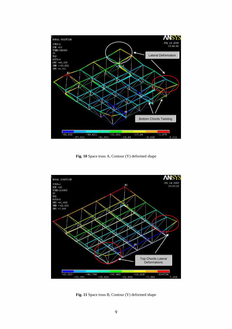
space truss A, the top members have suffer from large lateral deformation especially at the corners
while the bottom chords suffer from twisting and this can be noticed from the Fig. 10.
8
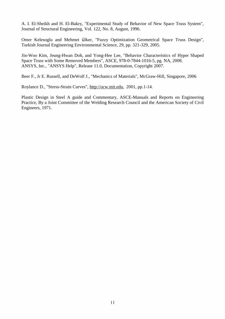
For space truss B, the top chord members especially in those members close to the corner
diagonals suffer from lateral deformations and this can be noticed from Fig. 11.
Fig. 8 Load-Deflection relationship: analytical-experimental comparison
of space truss A
Fig.9 Load-Deflection relationship: analytical-experimental comparison
of space truss B
0 10 20 30 40 50
Central Deflection (mm)
0
100
200
300
400
To
tal L
oa
d (
kN
)
Space Truss A
Experimental Results by Ahmed El-Sheikh, 1996
Analytical Results by Present Study
0 5 10 15 20 25 30 35
Central Deflection (mm)
0
50
100
150
200
250
To
tal L
oad
(kN
)
Space Truss B
Experimental Results by Ahmed El-Sheikh, 1996
Analytical Results by Present Study
Ultimate Tensile Strength Necking
9
Fig. 10 Space truss A, Contour (Y) deformed shape
Fig. 11 Space truss B, Contour (Y) deformed shape
Lateral Deformation
Bottom Chords Twisting
Top Chords Lateral Deformations

11
Table 1 Comparison of ultimate loads predicted by ANSYS 11.0 with experimental values
Specimens
Ultimate Load Pu (kN)
EXPT)Pu(
ANSYS)Pu(
Central Deflection c (mm)
EXPT)u(
ANSYS)u(
(Pu)ANSYS (Pu)EXPT
(c )ANSYS (c )EXPT
Truss A
Truss B
390 390
218 218
1
1
47.45 47
32.65 32
1.01
1.02
Conclusions:
The three-dimensional finite element (ANSYS 11.0) models were used to represent the space truss,
top chord members rectangular hollow sections (RHS), bottom chord members, and diagonal
members circular hollow sections (CHS) and found to be efficient to simulate these space trusses. In
general it can be said that there was good agreement between the analytical and the experimental
load-deflection curves at the center of the space truss. Also the finite element models of the space
truss simulate the lateral deflection of the top chord members especially at the corners of the truss A
and B, and the twisting of the bottom chords, this behavior was reflect in overall ductile
performances of the space truss, in other word the trusses could withstand gradual losses of stiffness
induced by several cases of bottom member yielding and top member lateral deformation.
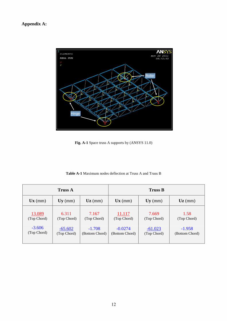
And from the analysis before it can be conclusion that the corner parts in the space truss are
the most critical parts and their twist are due to lateral twisting of the top chords and this lead to
failure of the whole structure. So from figure 12 which shows the supports type which are two
hinges at two ends and tow rollers at the other opposite ends, and from table 2 in addition to figures
13 and 14 as shown in the appendix A below, it can be notice that the maximum deflections in the
three axis (x, y and z) occurred at the hinge supports for space truss A, while they occurred in space
truss B at the roller support, and this can be justify to the difference in the design between the two
trusses A (with overdesigned top chord members (by 30%)) and truss B (with underdesigned top
chord members (by 40%)).
References:
Ahmed El-Sheikh, "Development of a New Space Truss System", Journal Construction of Steel
Research, Elsevier, Vol. 37, No. 3 pp. 205-227, 1996.
Henning Agerksov, "Optimum Geometry Design of Double-Layer Space Trusses", Journal of
Structural Engineering, Vol. 112, No. 6, June, 1986.
Erling Murtha-Smith, "Alternate Path Analysis of Space Trusses for Progressive Collapse", Journal
of Structural Engineering, Vol. 114, No. 9, September, 1988.
Christopher D. Hill, Goerge E. Blandford, and Shein T. Wang, "Post-Buckling Analysis of Steel
Space Trusses", Journal of Structural Engineering, Vol. 115, No. 4, April, 1989.
11
A. I. El-Sheikh and H. El-Bakry, "Experimental Study of Behavior of New Space Truss System",
Journal of Structural Engineering, Vol. 122, No. 8, August, 1996.
Omer Kelesoglu and Mehmet ülker, "Fuzzy Optimization Geometrical Space Truss Design",
Turkish Journal Engineering Environmental Science, 29, pp. 321-329, 2005.
Jin-Woo Kim, Jeung-Hwan Doh, and Yong-Hee Lee, "Behavior Characteristics of Hyper Shaped
Space Truss with Some Removed Members", ASCE, 978-0-7844-1016-5, pg. NA, 2008.
ANSYS, Inc., "ANSYS Help", Release 11.0, Documentation, Copyright 2007.
Beer F., Jr E. Russell, and DeWolf J., "Mechanics of Materials", McGraw-Hill, Singapore, 2006
Roylance D., "Stress-Strain Curves", http://ocw.mit.edu, 2001, pp.1-14.
Plastic Design in Steel A guide and Commentary, ASCE-Manuals and Reports on Engineering
Practice, By a Joint Committee of the Welding Research Council and the American Society of Civil
Engineers, 1971.
12
Appendix A:
Fig. A-1 Space truss A supports by (ANSYS 11.0)
Table A-1 Maximum nodes deflection at Truss A and Truss B
Truss A
Truss B
Ux (mm)
Uy (mm)
Uz (mm)
Ux (mm)
Uy (mm)
Uz (mm)
13.089
(Top Chord)
-3.606 (Top Chord)
6.311 (Top Chord)
-65.602 (Top Chord)
7.167 (Top Chord)
-1.708 (Bottom Chord)
11.117 (Top Chord)
-0.0274 (Bottom Chord)
7.669 (Top Chord)
-61.023 (Top Chord)
1.58 (Top Chord)
-1.958 (Bottom Chord)
Hinge
Roller
13
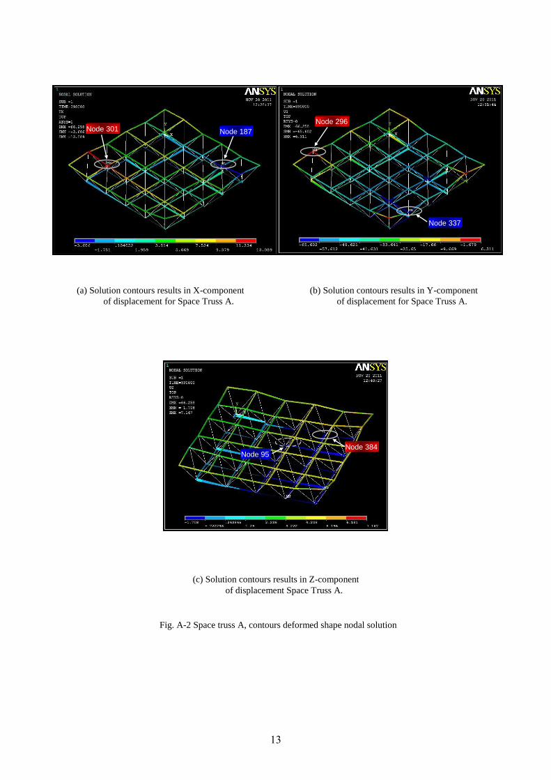
(a) Solution contours results in X-component
of displacement for Space Truss A.
(b) Solution contours results in Y-component
of displacement for Space Truss A.
(c) Solution contours results in Z-component
of displacement Space Truss A.
Node 301 Node 187
Node 296
Node 337
Node 384 Node 95
Fig. A-2 Space truss A, contours deformed shape nodal solution
14
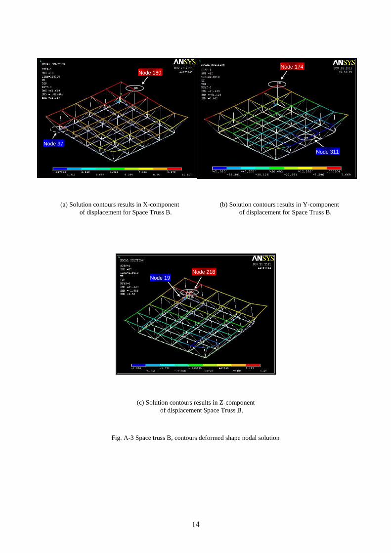
Node 311
Node 97
Node 19 Node 218
Node 174 Node 180
(a) Solution contours results in X-component
of displacement for Space Truss B.
(b) Solution contours results in Y-component
of displacement for Space Truss B.
(c) Solution contours results in Z-component
of displacement Space Truss B.
Fig. A-3 Space truss B, contours deformed shape nodal solution
Related Documents


