REVIEW Noninvasive Assessment of the Biventricular Pacing System Jonathan S. Steinberg, M.D., ∗ Parimal B. Maniar, M.D., ∗ Steven L. Higgins, M.D.,† Sherie L. Whiting, R.N.,† David B. Meyer, M.D.,† Sergio Dubner, M.D.,§ Abrar H. Shah, M.D.,¶ David T. Huang, M.D.,¶ and Leslie A. Saxon, M.D.‡ From the ∗ Division of Cardiology and Arrhythmia Service, St. Luke’s–Roosevelt Hospital Center and Columbia University, New York; †Scripps Hospital, La Jolla, California; ¶Division of Cardiology, University of Rochester, Rochester, New York; §Clinica Y Maternidad Suizo Argentina, Buenos Aires, Argentina; and ‡Division of Cardiology, University of Southern California, Los Angeles, California Cardiac resynchronization using biventricular (BiV) pacing systems has been introduced for the treatment of symptomatic heart failure in patients with bundle branch block or prolonged QRS dura- tion. Recent controlled clinical trials 1,2 have con- cluded and the results indicate that the majority of carefully selected patients will experience clinical improvement. The Food and Drug Administration has recently approved BiV pacing systems for im- plantation in patients with NYHA class III–IV heart failure despite optimal medical therapy when the QRS duration is >130 ms. The BiV pacing system differs from the con- ventional permanent pacemaker by incorporating a third lead that is positioned on the epicardial surface of the left ventricle (LV) via the coronary venous system. Simultaneous stimulation of the right ventricle (RV) (via a conventional endocar- dial lead) and the LV accomplishes BiV pacing and “resynchronizes” ventricular activation. This non- traditional format of ventricular stimulation may present new challenges in the assessment of pacing function, and will necessitate a greater understand- ing of basic and complex features of BiV pacing and its effect on noninvasive modalities such as the electrocardiogram (ECG) and intracardiac record- ings on the pacemaker programmers. Initial sys- tems utilized a conventional pulse generator with a modified header where LV and RV signals and output were linked; systems with separate ports for the LV and RV are now available. Address for reprints: Jonathan S. Steinberg, M.D., Division of Cardiology, St. Luke’s-Roosevelt Hospital Center, 1111 Amsterdam Avenue, New York, NY 10025. Fax: (212) 523-3915; E-mail: [email protected] Many variables, in addition to the basic lead configuration, can influence accurate assessment of BiV pacer function, including LV and RV lead position, consistency of capture, differences in impedance between the ventricular leads, conduc- tion velocity and patterns, relative timing of stimu- lation between the ventricular channels, and fusion with intrinsic activation. New and unusual sensing problems can arise creating complications such as pacemaker-mediated tachycardia or inappropriate inhibition. Pacemaker programming also involves issues unrelated to combating bradycardia. This review will focus on performing a noninva- sive assessment of the BiV pacing system using the 12-lead ECG and intracardiac electrograms, analy- ses of sensing and capture functions, and general programming recommendations. TWELVE-LEAD ECG The ECG is the most readily available tool to ascertain whether BiV pacing has been success- fully accomplished, and whether sensing or capture problems exist. The ECG can provide a permanent template of capture configurations (e.g., no pacing, RV, LV, BiV) for easy and reliable troubleshooting. Current BiV systems usually pace BiV via a unipo- lar LV lead as a common anode attached to the RV tip versus a ring or proximal shared electrode also on the RV lead. They may also pace in a unipolar 58

Welcome message from author
This document is posted to help you gain knowledge. Please leave a comment to let me know what you think about it! Share it to your friends and learn new things together.
Transcript
REVIEW
Noninvasive Assessment of the BiventricularPacing System
Jonathan S. Steinberg, M.D.,∗ Parimal B. Maniar, M.D.,∗ Steven L. Higgins, M.D.,†Sherie L. Whiting, R.N.,† David B. Meyer, M.D.,† Sergio Dubner, M.D.,§Abrar H. Shah, M.D.,¶ David T. Huang, M.D.,¶ and Leslie A. Saxon, M.D.‡From the ∗Division of Cardiology and Arrhythmia Service, St. Luke’s–Roosevelt Hospital Center and ColumbiaUniversity, New York; †Scripps Hospital, La Jolla, California; ¶Division of Cardiology, University of Rochester,Rochester, New York; §Clinica Y Maternidad Suizo Argentina, Buenos Aires, Argentina; and ‡Division ofCardiology, University of Southern California, Los Angeles, California
Cardiac resynchronization using biventricular(BiV) pacing systems has been introduced for thetreatment of symptomatic heart failure in patientswith bundle branch block or prolonged QRS dura-tion. Recent controlled clinical trials1,2 have con-cluded and the results indicate that the majority ofcarefully selected patients will experience clinicalimprovement. The Food and Drug Administrationhas recently approved BiV pacing systems for im-plantation in patients with NYHA class III–IV heartfailure despite optimal medical therapy when theQRS duration is >130 ms.
The BiV pacing system differs from the con-ventional permanent pacemaker by incorporatinga third lead that is positioned on the epicardialsurface of the left ventricle (LV) via the coronaryvenous system. Simultaneous stimulation of theright ventricle (RV) (via a conventional endocar-dial lead) and the LV accomplishes BiV pacing and“resynchronizes” ventricular activation. This non-traditional format of ventricular stimulation maypresent new challenges in the assessment of pacingfunction, and will necessitate a greater understand-ing of basic and complex features of BiV pacingand its effect on noninvasive modalities such as theelectrocardiogram (ECG) and intracardiac record-ings on the pacemaker programmers. Initial sys-tems utilized a conventional pulse generator witha modified header where LV and RV signals andoutput were linked; systems with separate ports forthe LV and RV are now available.
Address for reprints: Jonathan S. Steinberg, M.D., Division of Cardiology, St. Luke’s-Roosevelt Hospital Center, 1111 Amsterdam Avenue,New York, NY 10025. Fax: (212) 523-3915; E-mail: [email protected]
Many variables, in addition to the basic leadconfiguration, can influence accurate assessmentof BiV pacer function, including LV and RV leadposition, consistency of capture, differences inimpedance between the ventricular leads, conduc-tion velocity and patterns, relative timing of stimu-lation between the ventricular channels, and fusionwith intrinsic activation. New and unusual sensingproblems can arise creating complications such aspacemaker-mediated tachycardia or inappropriateinhibition. Pacemaker programming also involvesissues unrelated to combating bradycardia.
This review will focus on performing a noninva-sive assessment of the BiV pacing system using the12-lead ECG and intracardiac electrograms, analy-ses of sensing and capture functions, and generalprogramming recommendations.
TWELVE-LEAD ECG
The ECG is the most readily available tool toascertain whether BiV pacing has been success-fully accomplished, and whether sensing or captureproblems exist. The ECG can provide a permanenttemplate of capture configurations (e.g., no pacing,RV, LV, BiV) for easy and reliable troubleshooting.Current BiV systems usually pace BiV via a unipo-lar LV lead as a common anode attached to the RVtip versus a ring or proximal shared electrode alsoon the RV lead. They may also pace in a unipolar
58
A.N.E. � January 2004 � Vol. 9, No. 1 � Steinberg, et al. � Biventricular Pacing System � 59
mode from both tips to the pacemaker can. Rarely,both leads may be bipolar.
At implant, it is important to create capture tem-plates of four modes: intrinsic rhythm (by defini-tion, with an interventricular conduction delay),RV pacing only, LV pacing only, and BiV pacing.Individual chamber pacing can be accomplishedmanually by connecting only specifically neededelectrodes, in a unipolar format, to a pacemakeranalyzer. A 12-lead ECG template for each pacingconfiguration should be recorded and stored for ref-erence when needed.
The 12-lead ECG will vary in configuration be-tween the different pacing modes, although not al-ways in consistent patterns, or even predictablepatterns if limited leads are examined. Because thevector of activation will, by definition, differ be-tween the various possible capture modes, it hasbeen possible to develop some simple and logicalECG algorithms that can predict the presence ofBiV, LV, or RV capture. The need to confirm thesepatterns is evident for testing capture threshold ofthe individual lead components of the system, andvery importantly, to be confident of a fully func-tioning system during the clinical care of the heartfailure patient. In addition, the LV lead system isless stable and consistent than traditional RV leads.
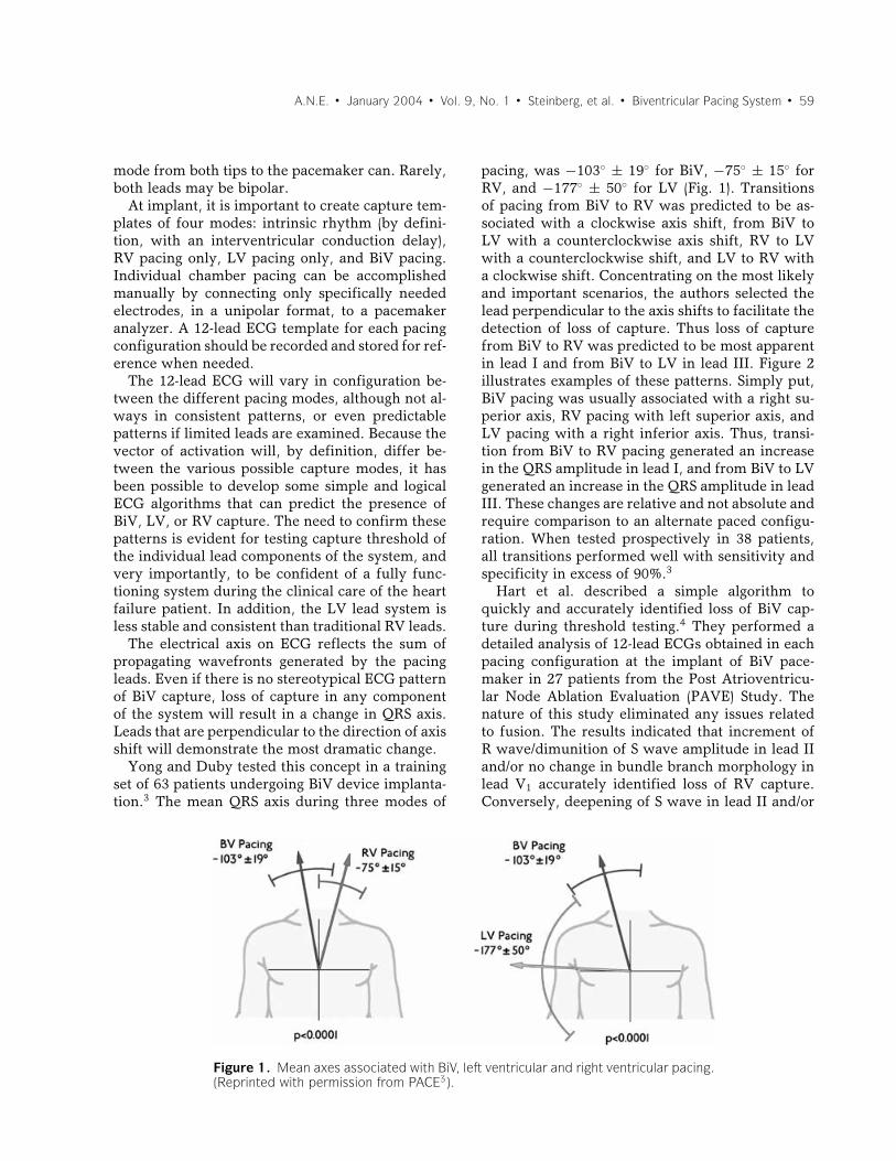
The electrical axis on ECG reflects the sum ofpropagating wavefronts generated by the pacingleads. Even if there is no stereotypical ECG patternof BiV capture, loss of capture in any componentof the system will result in a change in QRS axis.Leads that are perpendicular to the direction of axisshift will demonstrate the most dramatic change.
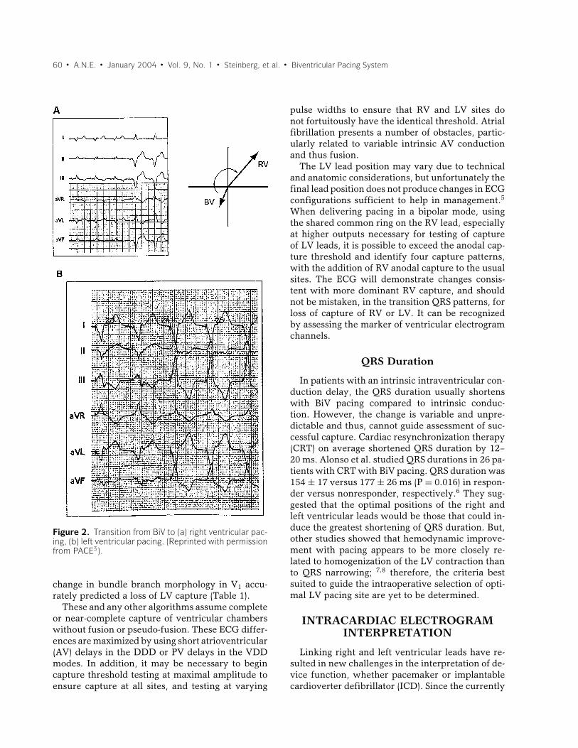
Yong and Duby tested this concept in a trainingset of 63 patients undergoing BiV device implanta-tion.3 The mean QRS axis during three modes of
Figure 1. Mean axes associated with BiV, left ventricular and right ventricular pacing.(Reprinted with permission from PACE3).
pacing, was −103◦ ± 19◦ for BiV, −75◦ ± 15◦ forRV, and −177◦ ± 50◦ for LV (Fig. 1). Transitionsof pacing from BiV to RV was predicted to be as-sociated with a clockwise axis shift, from BiV toLV with a counterclockwise axis shift, RV to LVwith a counterclockwise shift, and LV to RV witha clockwise shift. Concentrating on the most likelyand important scenarios, the authors selected thelead perpendicular to the axis shifts to facilitate thedetection of loss of capture. Thus loss of capturefrom BiV to RV was predicted to be most apparentin lead I and from BiV to LV in lead III. Figure 2illustrates examples of these patterns. Simply put,BiV pacing was usually associated with a right su-perior axis, RV pacing with left superior axis, andLV pacing with a right inferior axis. Thus, transi-tion from BiV to RV pacing generated an increasein the QRS amplitude in lead I, and from BiV to LVgenerated an increase in the QRS amplitude in leadIII. These changes are relative and not absolute andrequire comparison to an alternate paced configu-ration. When tested prospectively in 38 patients,all transitions performed well with sensitivity andspecificity in excess of 90%.3
Hart et al. described a simple algorithm toquickly and accurately identified loss of BiV cap-ture during threshold testing.4 They performed adetailed analysis of 12-lead ECGs obtained in eachpacing configuration at the implant of BiV pace-maker in 27 patients from the Post Atrioventricu-lar Node Ablation Evaluation (PAVE) Study. Thenature of this study eliminated any issues relatedto fusion. The results indicated that increment ofR wave/dimunition of S wave amplitude in lead IIand/or no change in bundle branch morphology inlead V1 accurately identified loss of RV capture.Conversely, deepening of S wave in lead II and/or
60 � A.N.E. � January 2004 � Vol. 9, No. 1 � Steinberg, et al. � Biventricular Pacing System
Figure 2. Transition from BiV to (a) right ventricular pac-ing, (b) left ventricular pacing. (Reprinted with permissionfrom PACE3).
change in bundle branch morphology in V1 accu-rately predicted a loss of LV capture (Table 1).
These and any other algorithms assume completeor near-complete capture of ventricular chamberswithout fusion or pseudo-fusion. These ECG differ-ences are maximized by using short atrioventricular(AV) delays in the DDD or PV delays in the VDDmodes. In addition, it may be necessary to begincapture threshold testing at maximal amplitude toensure capture at all sites, and testing at varying
pulse widths to ensure that RV and LV sites donot fortuitously have the identical threshold. Atrialfibrillation presents a number of obstacles, partic-ularly related to variable intrinsic AV conductionand thus fusion.
The LV lead position may vary due to technicaland anatomic considerations, but unfortunately thefinal lead position does not produce changes in ECGconfigurations sufficient to help in management.5
When delivering pacing in a bipolar mode, usingthe shared common ring on the RV lead, especiallyat higher outputs necessary for testing of captureof LV leads, it is possible to exceed the anodal cap-ture threshold and identify four capture patterns,with the addition of RV anodal capture to the usualsites. The ECG will demonstrate changes consis-tent with more dominant RV capture, and shouldnot be mistaken, in the transition QRS patterns, forloss of capture of RV or LV. It can be recognizedby assessing the marker of ventricular electrogramchannels.
QRS Duration
In patients with an intrinsic intraventricular con-duction delay, the QRS duration usually shortenswith BiV pacing compared to intrinsic conduc-tion. However, the change is variable and unpre-dictable and thus, cannot guide assessment of suc-cessful capture. Cardiac resynchronization therapy(CRT) on average shortened QRS duration by 12–20 ms. Alonso et al. studied QRS durations in 26 pa-tients with CRT with BiV pacing. QRS duration was154 ± 17 versus 177 ± 26 ms (P = 0.016) in respon-der versus nonresponder, respectively.6 They sug-gested that the optimal positions of the right andleft ventricular leads would be those that could in-duce the greatest shortening of QRS duration. But,other studies showed that hemodynamic improve-ment with pacing appears to be more closely re-lated to homogenization of the LV contraction thanto QRS narrowing; 7,8 therefore, the criteria bestsuited to guide the intraoperative selection of opti-mal LV pacing site are yet to be determined.
INTRACARDIAC ELECTROGRAMINTERPRETATION
Linking right and left ventricular leads have re-sulted in new challenges in the interpretation of de-vice function, whether pacemaker or implantablecardioverter defibrillator (ICD). Since the currently
A.N.E. � January 2004 � Vol. 9, No. 1 � Steinberg, et al. � Biventricular Pacing System � 61
Table 1. Positive and Negative Predictive Value of Two Major ECG Criteria Described toAccurately Identify Loss of BiV Capture by Hart et al.4
Positive Predictive Negative PredictiveValue (%) Value (%)
Transition from BiV to LV pacing1. Increment in R or dimunition in S wave in lead II 96 932. No change in BB morphology in lead V1 71 89
Criterion 1 and 2 100 93Criterion 1 or 2 100 100
Transition from BiV to RV pacing1. Deepening of S wave in lead II 93 962. Change in BB morphology in lead V1 89 71
Criterion 1 and 2 100 73Criterion 1 or 2 100 100
BiV = biventricular, LV = left ventricular, RV = right ventricular, and BB = bundle branch.
available first-generation systems do not permit in-dependent ventricular channel analysis, care mustbe taken in both demonstration of appropriatesensing and BiV capture. In addition, two leadsyoked together can result in potential interactionsthat warrant special diagnostic evaluation for trou-bleshooting. In the above section, the value of 12-lead EKG analyses in discriminating right and leftventricular pacemaker function is described. In thissection, we will review the additive value of intrac-ardiac electrogram analysis.
Threshold Determination
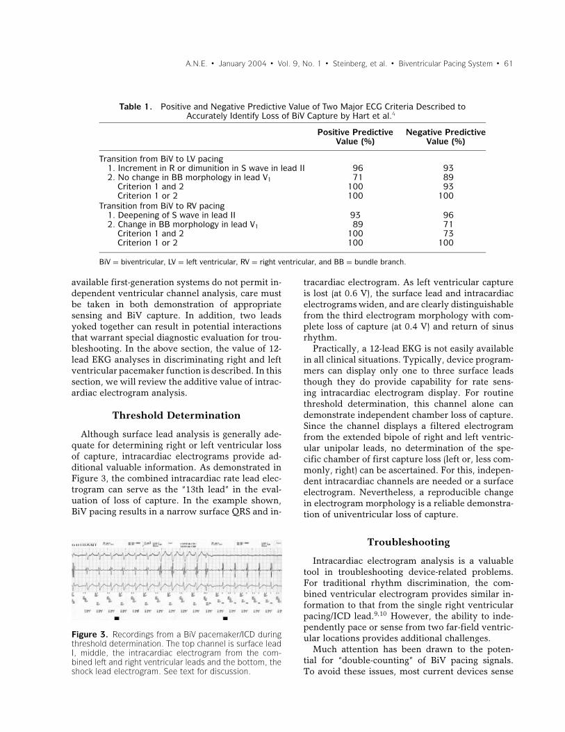
Although surface lead analysis is generally ade-quate for determining right or left ventricular lossof capture, intracardiac electrograms provide ad-ditional valuable information. As demonstrated inFigure 3, the combined intracardiac rate lead elec-trogram can serve as the “13th lead” in the eval-uation of loss of capture. In the example shown,BiV pacing results in a narrow surface QRS and in-
Figure 3. Recordings from a BiV pacemaker/ICD duringthreshold determination. The top channel is surface leadI, middle, the intracardiac electrogram from the com-bined left and right ventricular leads and the bottom, theshock lead electrogram. See text for discussion.
tracardiac electrogram. As left ventricular captureis lost (at 0.6 V), the surface lead and intracardiacelectrograms widen, and are clearly distinguishablefrom the third electrogram morphology with com-plete loss of capture (at 0.4 V) and return of sinusrhythm.
Practically, a 12-lead EKG is not easily availablein all clinical situations. Typically, device program-mers can display only one to three surface leadsthough they do provide capability for rate sens-ing intracardiac electrogram display. For routinethreshold determination, this channel alone candemonstrate independent chamber loss of capture.Since the channel displays a filtered electrogramfrom the extended bipole of right and left ventric-ular unipolar leads, no determination of the spe-cific chamber of first capture loss (left or, less com-monly, right) can be ascertained. For this, indepen-dent intracardiac channels are needed or a surfaceelectrogram. Nevertheless, a reproducible changein electrogram morphology is a reliable demonstra-tion of univentricular loss of capture.
Troubleshooting
Intracardiac electrogram analysis is a valuabletool in troubleshooting device-related problems.For traditional rhythm discrimination, the com-bined ventricular electrogram provides similar in-formation to that from the single right ventricularpacing/ICD lead.9,10 However, the ability to inde-pendently pace or sense from two far-field ventric-ular locations provides additional challenges.
Much attention has been drawn to the poten-tial for “double-counting” of BiV pacing signals.To avoid these issues, most current devices sense
62 � A.N.E. � January 2004 � Vol. 9, No. 1 � Steinberg, et al. � Biventricular Pacing System
from the right ventricular channel alone yet pro-vide BiV stimulation. Theoretically, the lack of leftventricular sensing poses the risk of undersensingof left ventricular events and thus inappropriatepacing, such as arrhythmia induction from the “Ron T” phenomenon. Practically, this is exceedinglyrare and regardless, should be promptly terminatedwhen the BiV device is an ICD and not a pacemakeralone.
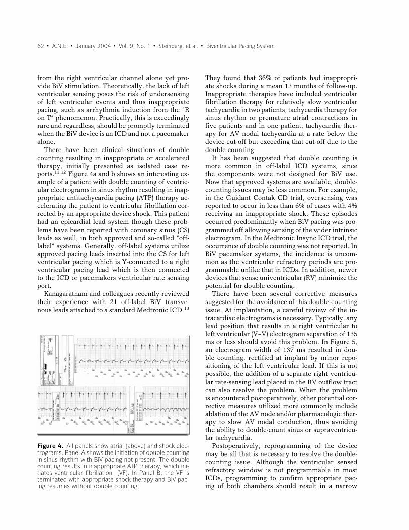
There have been clinical situations of doublecounting resulting in inappropriate or acceleratedtherapy, initially presented as isolated case re-ports.11,12 Figure 4a and b shows an interesting ex-ample of a patient with double counting of ventric-ular electrograms in sinus rhythm resulting in inap-propriate antitachycardia pacing (ATP) therapy ac-celerating the patient to ventricular fibrillation cor-rected by an appropriate device shock. This patienthad an epicardial lead system though these prob-lems have been reported with coronary sinus (CS)leads as well, in both approved and so-called “off-label” systems. Generally, off-label systems utilizeapproved pacing leads inserted into the CS for leftventricular pacing which is Y-connected to a rightventricular pacing lead which is then connectedto the ICD or pacemakers ventricular rate sensingport.
Kanagaratnam and colleagues recently reviewedtheir experience with 21 off-label BiV transve-nous leads attached to a standard Medtronic ICD.13
Figure 4. All panels show atrial (above) and shock elec-trograms. Panel A shows the initiation of double countingin sinus rhythm with BiV pacing not present. The doublecounting results in inappropriate ATP therapy, which ini-tiates ventricular fibrillation (VF). In Panel B, the VF isterminated with appropriate shock therapy and BiV pac-ing resumes without double counting.
They found that 36% of patients had inappropri-ate shocks during a mean 13 months of follow-up.Inappropriate therapies have included ventricularfibrillation therapy for relatively slow ventriculartachycardia in two patients, tachycardia therapy forsinus rhythm or premature atrial contractions infive patients and in one patient, tachycardia ther-apy for AV nodal tachycardia at a rate below thedevice cut-off but exceeding that cut-off due to thedouble counting.
It has been suggested that double counting ismore common in off-label ICD systems, sincethe components were not designed for BiV use.Now that approved systems are available, double-counting issues may be less common. For example,in the Guidant Contak CD trial, oversensing wasreported to occur in less than 6% of cases with 4%receiving an inappropriate shock. These episodesoccurred predominantly when BiV pacing was pro-grammed off allowing sensing of the wider intrinsicelectrogram. In the Medtronic Insync ICD trial, theoccurrence of double counting was not reported. InBiV pacemaker systems, the incidence is uncom-mon as the ventricular refractory periods are pro-grammable unlike that in ICDs. In addition, newerdevices that sense univentricular (RV) minimize thepotential for double counting.
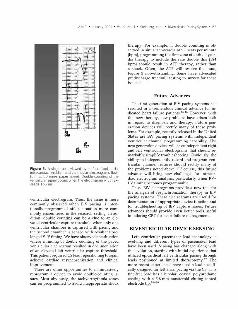
There have been several corrective measuressuggested for the avoidance of this double-countingissue. At implantation, a careful review of the in-tracardiac electrograms is necessary. Typically, anylead position that results in a right ventricular toleft ventricular (V–V) electrogram separation of 135ms or less should avoid this problem. In Figure 5,an electrogram width of 137 ms resulted in dou-ble counting, rectified at implant by minor repo-sitioning of the left ventricular lead. If this is notpossible, the addition of a separate right ventricu-lar rate-sensing lead placed in the RV outflow tractcan also resolve the problem. When the problemis encountered postoperatively, other potential cor-rective measures utilized more commonly includeablation of the AV node and/or pharmacologic ther-apy to slow AV nodal conduction, thus avoidingthe ability to double-count sinus or supraventricu-lar tachycardia.
Postoperatively, reprogramming of the devicemay be all that is necessary to resolve the double-counting issue. Although the ventricular sensedrefractory window is not programmable in mostICDs, programming to confirm appropriate pac-ing of both chambers should result in a narrow
A.N.E. � January 2004 � Vol. 9, No. 1 � Steinberg, et al. � Biventricular Pacing System � 63
Figure 5. A single beat viewed by surface (top), atrialintracardiac (middle), and ventricular electrograms (bot-tom) at 50 mm/s paper speed. Double counting of theventricular signal occurs when the electrogram width ex-ceeds 135 ms.
ventricular electrogram. Thus, the issue is morecommonly observed when BiV pacing is inten-tionally programmed off, a situation more com-monly encountered in the research setting. In ad-dition, double counting can be a clue to an ele-vated ventricular capture threshold when only oneventricular chamber is captured with pacing andthe second chamber is sensed with resultant pro-longed V–V timing. We have observed one situationwhere a finding of double counting of the pacedventricular electrogram resulted in documentationof an elevated left ventricular capture threshold.This patient required CS lead repositioning to againachieve cardiac resynchronization and clinicalimprovement.
There are other opportunities to noninvasivelyreprogram a device to avoid double-counting is-sues. Most obviously, the tachyarrhythmia zonescan be programmed to avoid inappropriate shock
therapy. For example, if double counting is ob-served in sinus tachycardia at 92 beats per minute(bpm), programming the first zone of antitachycar-dia therapy to include the rate double this (184bpm) should result in ATP therapy, rather thana shock. Often, the ATP will resolve the issue,Figure 5 notwithstanding. Some have advocatedpredischarge treadmill testing to survey for theseissues.14
Future Advances
The first generation of BiV pacing systems hasresulted in a tremendous clinical advance for in-dicated heart failure patients.15,16 However, withthis new therapy, new problems have arisen bothin regard to diagnosis and therapy. Future gen-eration devices will rectify many of these prob-lems. For example, recently released in the UnitedStates are BiV pacing systems with independentventricular channel programming capability. Thenext generation devices will have independent rightand left ventricular electrograms that should re-markably simplify troubleshooting. Obviously, theability to independently record and program ven-tricular channel features should rectify many ofthe problems noted above. Of course, this futureadvance will bring new challenges for intracar-diac electrogram analysis, particularly when RV–LV timing becomes programmable.
Thus, BiV electrograms provide a new tool forthe analysis of resynchronization therapy in BiVpacing systems. These electrograms are useful fordocumentation of appropriate device function andfor troubleshooting of BiV capture issues. Futureadvances should provide even better tools usefulin tailoring CRT for heart failure management.
BIVENTRICULAR DEVICE SENSING
Left ventricular pacemaker lead technology isevolving and different types of pacemaker leadhave been used. Sensing has changed along withthis evolution, starting with initial experience thatutilized epicardical left ventricular pacing throughleads positioned at limited thoracotomy.17 Themore recent experiences have used a lead specifi-cally designed for left atrial pacing via the CS. Thistine-free lead has a bipolar, coaxial polyurethanecoating with a 5.8-mm nonsteroid eluting cantedelectrode tip.18−20
64 � A.N.E. � January 2004 � Vol. 9, No. 1 � Steinberg, et al. � Biventricular Pacing System
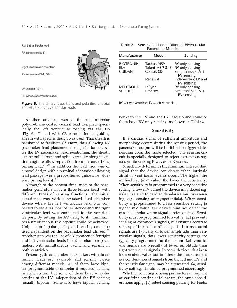
Figure 6. The different positions and polarities of atrialand left and right ventricular leads.
Another advance was a tine-free unipolarpolyurethane coated coaxial lead designed specif-ically for left ventricular pacing via the CS(Fig. 6). To aid with CS cannulation, a guidingsheath with specific design was used. This sheath ispreshaped to facilitate CS entry, thus allowing LVpacemaker lead placement through its lumen. Af-ter the LV pacemaker lead positioning, the sheathcan be pulled back and split externally along its en-tire length to allow separation from the underlyingpacing lead.21,22 In addition the lead used was ofa novel design with a terminal adaptation allowinglead passage over a prepositioned guidewire (side-wire pacing leads).23
Although at the present time, most of the pace-maker generators have a three-lumen head (withdifferent types of sensing functions), the initialexperience was with a standard dual chamberdevice where the left ventricular lead was con-nected to the atrial port of the device and the rightventricular lead was connected to the ventricu-lar port. By setting the AV delay to its minimum,near-simultaneous BiV capture could be achieved.Unipolar or bipolar pacing and sensing could beused dependent on the pacemaker lead utilized.20
Another step was the use of a Y connection for rightand left ventricular leads in a dual chamber pace-maker, with simultaneous pacing and sensing inboth ventricles.
Presently, three chamber pacemakers with three-lumen heads are available and sensing variesamong different models. All of them have bipo-lar (programmable to unipolar if required) sensingin right atrium; but some of them have unipolarsensing at the LV independent of the RV sensing(usually bipolar). Some also have bipolar sensing
Table 2. Sensing Options in Different BiventricularPacemaker Models
Manufacturer Model Sensing
BIOTRONIK Tachos MSV RV-only sensingELA Talent MSP 313 RV-only sensingGUIDANT Contak CD Simultaneous LV +
RV sensingRenewal Independent LV and
RV sensingMEDTRONIC InSync RV-only sensingSt. JUDE Frontier Simultaneous LV +
RV sensing
RV = right ventricle; LV = left ventricle.
between the RV and the LV lead tip and some ofthem have RV-only sensing, as shown in Table 2.
Sensitivity
If a cardiac signal of sufficient amplitude andmorphology occurs during the sensing period, thepacemaker output will be inhibited or triggered de-pending upon the mode selected. The sensing cir-cuit is specially designed to reject extraneous sig-nals while sensing P waves or R waves.
Sensitivity determines the minimum intracardiacsignal that the device can detect when intrinsicatrial or ventricular events occur. The higher themillivoltage (mV) value, the lower the sensitivity.When sensitivity is programmed to a very sensitivesetting (a low mV value) the device may detect sig-nals unrelated to cardiac depolarization (oversens-ing, e.g., sensing of myopotentials). When sensi-tivity is programmed to a less sensitive setting (ahigher mV value) the device may not detect thecardiac depolarization signal (undersensing). Sensi-tivity must be programmed to a value that preventssensing of extraneous signals, but ensures accuratesensing of intrinsic cardiac signals. Intrinsic atrialsignals are typically of lower amplitude than ven-tricular signals, thus lower sensitivity settings aretypically programmed for the atrium. Left ventric-ular signals are typically of lower amplitude thanright ventricular signals. In some devices, this is anindependent value but in others the measurementis a combination of signals from the left and RV andthe ventricular signal may be attenuated. So, sensi-tivity settings should be programmed accordingly.
Whether selecting sensing parameters at implantor verifying sensing at follow-up, the same consid-erations apply: (1) select sensing polarity for leads;
A.N.E. � January 2004 � Vol. 9, No. 1 � Steinberg, et al. � Biventricular Pacing System � 65
(2) determine sensing thresholds; and (3) select ap-propriate sensitivity settings.
Bipolar RV/LV Sensing Polarity
In the unipolar LV lead, the electrical activity willbe sensed between the LV lead tip and the RV leadring. The distance traveled by the stimulus betweenthe LV lead tip and the RV lead ring will be affectedby the size of the heart. The greater the distance, themore prone the device is to sensing myopotentials.
Determining Sensing Thresholdat Implant
Before connecting a lead, the implanting physi-cian should measure the sensing potentials in theunipolar and the bipolar configurations. Adequateintracardiac signal should be present in both con-figurations to ensure proper sensing in either.
Verifying Sensing Threshold at Follow-Up
Intracardiac signal amplitudes decrease duringthe lead maturation process. Most programmersprovide an automatic sensitivity test that allows thefollow-up clinician to verify a patient’s sensitivitysettings. The automatic test provides for atrial orventricular monitoring. The test provides the sen-sitivity setting just above and below the point atwhich P waves or R waves are sensed.
The cardiac signal presented to the stimulator bythe ventricular two-lead system is a composite sig-nal from the parallel combination of both ventric-ular leads in some devices. The sensing test treatsthis signal as a single input with measurable am-plitude that can be used to determine an appro-priate setting for ventricular sensitivity. Usuallythis signal may be attenuated in the BiV configu-ration. Conducting the sensing test for the ventric-ular two-lead system does not require any specialconsiderations.
Pitfalls and Solutions
Sensing RV only, or in both ventricles, togetheror separately, during pacing or in sinus rhythmshould modify the response of the system. The dif-ferences between these situations, as well as doublecounting of T waves and farfield noise, should beaddressed.
A system that senses RV-only may not detect anectopic beat that originated in the LV and may stim-
ulate during the refractory period. On the otherhand, any intrinsic ventricular action inhibits de-livery of a ventricular pulse in the DDD mode. Theventricles are not brought into synchrony with eachother.
A system that senses both the RV and LV leads inthe presence of a QRS > 130 ms may double sensea sinus rhythm event. This situation is true onlywhen the patient’s P-R interval is shorter than theprogrammed AV delay, and/or there are no pacingbeats at the ventricles. A similar situation could beseen if the sensing delay of both ventricles is greaterthan the ventricular refractory period.
Although optimal performance of a BiV devices’sensing has yet to be determined, some manufac-turers have modified the sensing system to avoidthese problems and others have introduced theDDT(R)/V mode and the LV protection period.
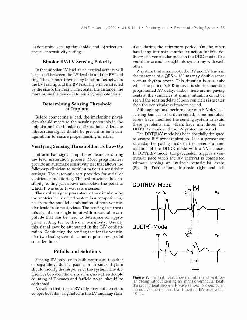
The DDT(R)/V mode has been specially designedto ensure BiV synchronization. It is a permanentrate-adaptive pacing mode that represents a com-bination of the DDDR mode with a VVT mode.In DDT(R)/V mode, the pacemaker triggers a ven-tricular pace when the AV interval is completedwithout sensing an intrinsic ventricular event(Fig. 7). Furthermore, intrinsic right and left
Figure 7. The first beat shows an atrial and ventricu-lar pacing without sensing an intrinsic ventricular beat;the second beat shows a P wave sensed followed by anintrinsic ventricular beat that triggers a BiV pace within10 ms.
66 � A.N.E. � January 2004 � Vol. 9, No. 1 � Steinberg, et al. � Biventricular Pacing System
ventricular senses trigger a BiV pace within 10 ms.Thus, the pacemaker response in the ventricularchannel corresponds to a VVT mode, and its atrialor AV-sequential behavior is analogous to a DDDmode. The clinical benefit of the DDT(R)/V modeis based on the ability to resynchronize both ven-tricles even during ventricular sense events.
Sensing on the LV channel, as well as the RV,could help avoid a pace during the refractory periodafter a premature ventricular beat (PVC). The fol-lowing example could help to understand the case:in the presence of PVC originated in the lateral wallof the LV, if the device senses only the RV, it maynot see the PVC and will pace the RV and the LV(possibly during the vulnerable period). To avoidthis situation, some devices sense the LV and allowyou to program the refractory period during whichthere is no chance to stimulate the LV if there wasa sensed activity.
PACING AND CAPTURE FUNCTIONOF THE BIVENTRICULAR
PACEMAKER
Left Ventricle Lead Capture
The success rate of implanting transvenous BiVpacing devices in major studies is approaching 80–92%18,24 and complication rates related to the pro-cedure are within acceptable range. In a recentstudy, only 4% patients had CS dissection and 2%had a cardiac vein or CS perforation.2 Completeheart block and cardiac arrest occurred in 1.2% ofpatients. Early lead dislodgment requiring reposi-tioning occurs in 5% patients.18 The left ventricularlead may also become dislodged and is reported tooccur in 4–6% of patients.2,25
Capture Thresholds
Long-term pacing thresholds in reported stud-ies are less than 2 volts with a mean impedanceof 694 ± 243 Ohms and sensing mean amplitudeof 11 mV.18 Acceptable capture threshold can beachieved in most cases with reported mean pacingthreshold of around 1 V/0.5 ms at the time of im-plantation and increased slightly up to <2 V/0.5 msduring follow-up.20,26 LV pacing thresholds of epi-cardial leads placed through the CS venous struc-tures are usually greater than RV pacing thresholds.In some BiV cases it is difficult to find a LV pac-ing site below 3.0 V. An acute LV pacing thresholdof greater than 3.0 V is considered too high for a
chronic system implant. Recent study has shownthat chronic CRT may actually lead to a decreasein ventricular capture thresholds over time. The eti-ology for this cannot be explained by improvinginflammation at the implant site but may be dueto a direct result of CRT. In the MIRACLE studythe threshold increased from 2.09 ± 1.43 to 2.27 ±1.17 volts in a patient randomized to no BiV pac-ing and reduced from 2.00 ± 1.65 to 1.74 ± 0.78volt in a patient with BiV pacing.27 Delivering elec-trical current to two pacing leads with differentimpedances connected in parallel does not resultin a clinically significant increase in pacing thresh-old in one small study when compared to the pacingthresholds measured from each lead individually.28
The surface of the RV (+) electrode has an im-portant effect on the LV (–) capture. The larger theanode, the lower the LV(–) pacing threshold. Asa consideration, the pacing threshold of a LV (–)unipolar lead can be minimized by using the distalshocking coil as the RV anode (+) in ICD systems.29
CRT to date has been delivered mostly via si-multaneous BiV pacing pulses, using tied out-puts. Newer BiV devices have independent pro-grammable outputs for both right and LV. Asidefrom potential hemodynamic advantages of pro-grammable differential timing of right and left ven-tricular pacing, there may be electrotonic advan-tages as well. If both pacing pulses are deliveredsimultaneously from capacitive coupled outputsprogrammed to different pacing voltages, this willcreate unexpected output-to-output current path-ways, and may increase capture thresholds. Cap-ture thresholds of two sites during simultaneousBiV pacing can be higher than the capture thresh-olds of those same sites paced individually. Separat-ing the simultaneous pacing pulses by 1 ms avoidscomplex intersite current pathways and keeps cap-ture thresholds to their individual lowest levels.30
LV and RV Pacing Sites
Pacing the midlateral area or posterior area ofthe LV in patients with left bundle branch block(LBBB) leads to greater improvements in pulse pres-sure and dP/dt than pacing anterior or apical LVsites.31 The superior anterior septum can be pacedfrom the anterior interventricular vein, the LV lat-eral free wall from the left marginal vein, and theposteroinferior portion of the LV from the left pos-terior vein. In 75% of patients the septal RV pacingQRS duration is shorter than the apical RV pacing
A.N.E. � January 2004 � Vol. 9, No. 1 � Steinberg, et al. � Biventricular Pacing System � 67
QRS duration for a given LV pacing site. Therefore,if only one RV site is to be selected for a BiV system,the mid-RV septum or outflow tract is preferablewhenever possible.32,33
Anodal Capture
In second-generation devices with independentventricular outputs the RV ring electrode can beincluded in both LV and RV pacing configurations.Stimulation initiated at the RV ring electrode (i.e.,anodal capture) has been observed. Steinhaus et al.evaluated the RV lead ring effects on anodal cap-ture.34 They showed that multiple RV lead types ex-hibit anodal capture and therefore loss of sequentialpacing can occur with all lead types. They found nostatistical significance in anodal capture thresholdbetween ring types or fixation types. Collectivelythere is no statistical significance in anodal capturethreshold for the RV lead positions studied. Accord-ing to their data, the majority of patients can be pro-grammed > 2 × safety margin chronically withoutanodal capture.
Diaphragmatic Stimulation
Optimal BiV pacing requires insertion of a leadin a posterior, posterolateral, or lateral coronaryvein. Their epicardial position and proximity to thediaphragm and left phrenic nerve make diaphrag-matic stimulation more likely than with conven-tional pacing. Clinically, diaphragmatic stimulationis posture dependent, particularly in left decubitusposition, while the LV capture threshold does notchange significantly according to body positions.35
Because it is often position dependent, diaphrag-matic stimulation can occur clinically even afternegative intraoperative supine testing. A low LVcapture threshold is thus important to allow safereprogramming if unexpected diaphragmatic stim-ulation develops.
Pacing and Capturing Complications
Left ventricular pacing lead through the CS hashigher dislodgment rate as compared to right ven-tricular pacing lead. Loss of LV pacing captureshould be ruled out in patients with worsening ofcongestive heart failure. Patients with a higher ini-tial LV pacing threshold are more likely to experi-ence dislodgment. Dislodgment is 1.5 times morelikely to occur in patients with a posterior lead po-sition.36 Perforation of the CS lead should also be
considered in any patient with an acute increasein left ventricular pacing threshold or loss of leftventricular pacing capture.
Exit block at the CS lead may limit the efficacyof ventricular resynchronization therapy. Despiteprogrammed safety margin of the stimulation pa-rameters, exit block occurs in a high percentage ofpatients in early studies with BiV pacemaker sys-tems.37 With the availability of separate program-ming of the left and right ventricle output in BiV de-vices the difficulty of exit block can be overcome.
PROGRAMMING THEBIVENTRICULAR DEVICE: ATRIAL
VENTRICULAR TIMING
Acute Optimization of the AV Interval
The majority of acute benefit resulting from CRTis on measures of systolic response and is inde-pendent of the programmed AV interval. Yet, left-sided AV timing is clearly an important considera-tion in the programming of resynchronization de-vices. Appropriate AV interval timing can maxi-mize the benefit of CRT and if programmed poorly,has the potential to curtail the beneficial effects.Unfortunately, there are no prospectively testedcriteria that define the best methods of measur-ing or assessing the effects of AV interval pro-gramming. The most widely used measures areacute hemodynamic measures of forward outputand echo/Doppler assessments.38−45
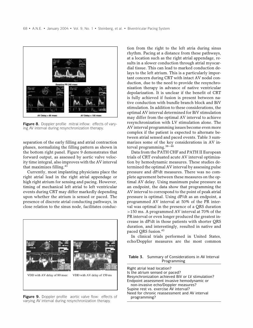
The goals of AV interval programming duringCRT are to select the AV interval that optimizesboth left ventricular filling and forward stroke vol-ume (Figs. 8, 9). In Figure 8, three mitral inflowDoppler profiles are shown. In the top panel, dur-ing baseline sinus rhythm with at a prolonged PRinterval of 240 ms, mitral E and A waves are fused.This is due to atrial contraction beginning in earlydiastole resulting in atrial contraction becoming su-perimposed upon the early left ventricular fillingphase. This causes curtailed ventricular filling. Ifatrial relaxation then occurs when left ventricularend-diastolic pressure rises, so that it exceeds leftatrial pressure, diastolic mitral regurgitation maybe observed. The lower left panel illustrates a veryshort programmed AV interval of 80 ms. In thisinstance atrial contraction occurs at the onset ofventricular systole, against a closed mitral valve.Programming the AV interval to 150 ms results in
68 � A.N.E. � January 2004 � Vol. 9, No. 1 � Steinberg, et al. � Biventricular Pacing System
Figure 8. Doppler profile mitral inflow: effects of vary-ing AV interval during resynchronization therapy.
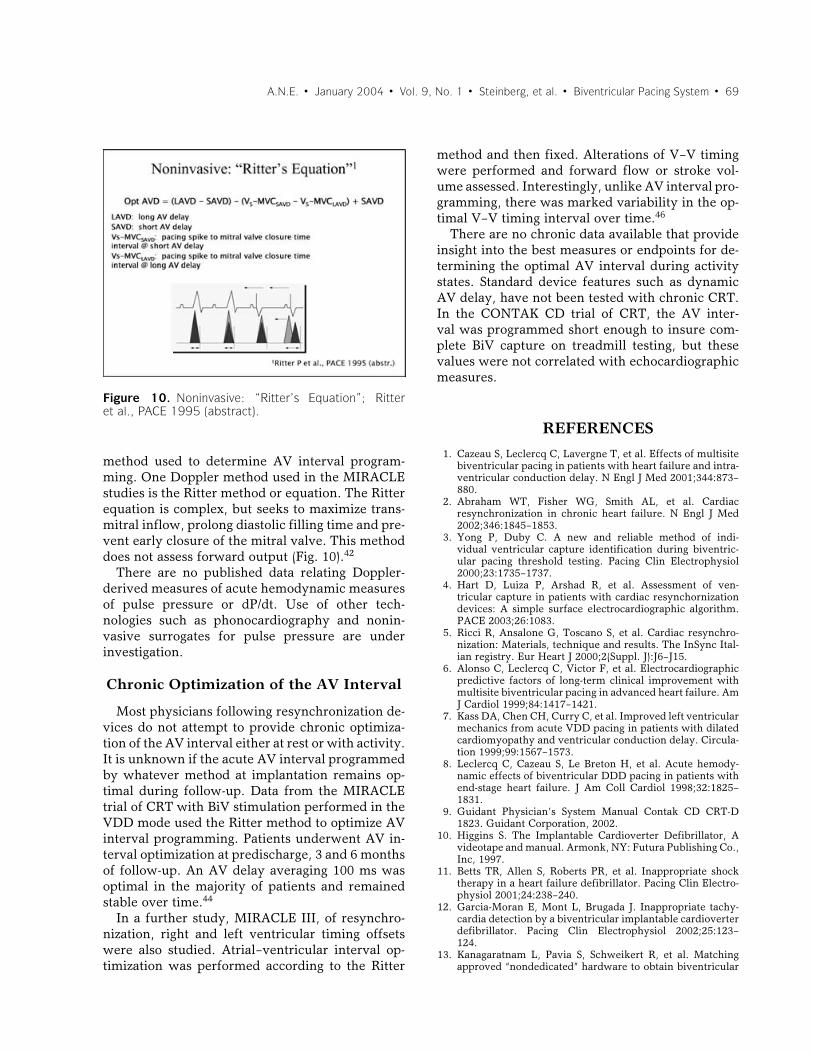
separation of the early filling and atrial contractionphases, normalizing the filling pattern as shown inthe bottom right panel. Figure 9 demonstrates thatforward output, as assessed by aortic valve veloc-ity time integral, also improves with the AV intervalthat maximizes filling.43
Currently, most implanting physicians place theright atrial lead in the right atrial appendage orhigh right atrium for sensing and pacing. However,timing of mechanical left atrial to left ventricularevents during CRT may differ markedly dependingupon whether the atrium is sensed or paced. Thepresence of discrete atrial conducting pathways, inclose relation to the sinus node, facilitates conduc-
Figure 9. Doppler profile aortic valve flow: effects ofvarying AV interval during resynchronization therapy.
tion from the right to the left atria during sinusrhythm. Pacing at a distance from these pathways,at a location such as the right atrial appendage, re-sults in a slower conduction through atrial myocar-dial tissue. This can lead to marked conduction de-lays to the left atrium. This is a particularly impor-tant concern during CRT with intact AV nodal con-duction, due to the need to provide the resynchro-nization therapy in advance of native ventriculardepolarization. It is unclear if the benefit of CRTis fully achieved if fusion is present between na-tive conduction with bundle branch block and BiVstimulation. In addition to these considerations, theoptimal AV interval determined for BiV stimulationmay differ from the optimal AV interval to achieveresynchronization with LV stimulation alone. TheAV interval programming issues become even morecomplex if the patient is expected to alternate be-tween atrial sensed and paced events. Table 3 sum-marizes some of the key considerations in AV in-terval programming.38−46
Data from the PATH CHF and PATH II Europeantrials of CRT evaluated acute AV interval optimiza-tion by hemodynamic measures. These studies de-termined the optimal AV interval by assessing pulsepressure and dP/dt measures. There was no com-plete agreement between these measures on the op-timal AV delay. Using maximum pulse pressure asan endpoint, the data show that programming theAV interval to correspond to the point of peak atrialpressure is optimal. Using dP/dt as an endpoint, aprogrammed AV interval at 50% of the PR inter-val was optimal in the presence of a QRS duration>150 ms. A programmed AV interval at 70% of thePR interval or even longer produced the greatest in-crease in dP/dt in those patients with shorter QRSduration, and interestingly, resulted in native andpaced QRS fusion.43
In clinical trials performed in United States,echo/Doppler measures are the most common
Table 3. Summary of Considerations in AV IntervalProgramming
Right atrial lead location?Is the atrium sensed or paced?Resynchronization achieved BiV or LV stimulation?Endpoint assessment invasive hemodynamic or
non-invasive echo/Doppler measures?Supine rest vs. exercise AV interval?Need for chronic reassessment and AV interval
programming?
A.N.E. � January 2004 � Vol. 9, No. 1 � Steinberg, et al. � Biventricular Pacing System � 69
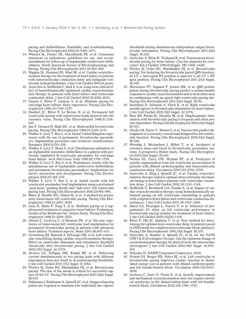
Figure 10. Noninvasive: “Ritter’s Equation”; Ritteret al., PACE 1995 (abstract).
method used to determine AV interval program-ming. One Doppler method used in the MIRACLEstudies is the Ritter method or equation. The Ritterequation is complex, but seeks to maximize trans-mitral inflow, prolong diastolic filling time and pre-vent early closure of the mitral valve. This methoddoes not assess forward output (Fig. 10).42
There are no published data relating Doppler-derived measures of acute hemodynamic measuresof pulse pressure or dP/dt. Use of other tech-nologies such as phonocardiography and nonin-vasive surrogates for pulse pressure are underinvestigation.
Chronic Optimization of the AV Interval
Most physicians following resynchronization de-vices do not attempt to provide chronic optimiza-tion of the AV interval either at rest or with activity.It is unknown if the acute AV interval programmedby whatever method at implantation remains op-timal during follow-up. Data from the MIRACLEtrial of CRT with BiV stimulation performed in theVDD mode used the Ritter method to optimize AVinterval programming. Patients underwent AV in-terval optimization at predischarge, 3 and 6 monthsof follow-up. An AV delay averaging 100 ms wasoptimal in the majority of patients and remainedstable over time.44
In a further study, MIRACLE III, of resynchro-nization, right and left ventricular timing offsetswere also studied. Atrial–ventricular interval op-timization was performed according to the Ritter
method and then fixed. Alterations of V–V timingwere performed and forward flow or stroke vol-ume assessed. Interestingly, unlike AV interval pro-gramming, there was marked variability in the op-timal V–V timing interval over time.46
There are no chronic data available that provideinsight into the best measures or endpoints for de-termining the optimal AV interval during activitystates. Standard device features such as dynamicAV delay, have not been tested with chronic CRT.In the CONTAK CD trial of CRT, the AV inter-val was programmed short enough to insure com-plete BiV capture on treadmill testing, but thesevalues were not correlated with echocardiographicmeasures.
REFERENCES
1. Cazeau S, Leclercq C, Lavergne T, et al. Effects of multisitebiventricular pacing in patients with heart failure and intra-ventricular conduction delay. N Engl J Med 2001;344:873–880.
2. Abraham WT, Fisher WG, Smith AL, et al. Cardiacresynchronization in chronic heart failure. N Engl J Med2002;346:1845–1853.
3. Yong P, Duby C. A new and reliable method of indi-vidual ventricular capture identification during biventric-ular pacing threshold testing. Pacing Clin Electrophysiol2000;23:1735–1737.
4. Hart D, Luiza P, Arshad R, et al. Assessment of ven-tricular capture in patients with cardiac resynchornizationdevices: A simple surface electrocardiographic algorithm.PACE 2003;26:1083.
5. Ricci R, Ansalone G, Toscano S, et al. Cardiac resynchro-nization: Materials, technique and results. The InSync Ital-ian registry. Eur Heart J 2000;2(Suppl. J):J6–J15.
6. Alonso C, Leclercq C, Victor F, et al. Electrocardiographicpredictive factors of long-term clinical improvement withmultisite biventricular pacing in advanced heart failure. AmJ Cardiol 1999;84:1417–1421.
7. Kass DA, Chen CH, Curry C, et al. Improved left ventricularmechanics from acute VDD pacing in patients with dilatedcardiomyopathy and ventricular conduction delay. Circula-tion 1999;99:1567–1573.
8. Leclercq C, Cazeau S, Le Breton H, et al. Acute hemody-namic effects of biventricular DDD pacing in patients withend-stage heart failure. J Am Coll Cardiol 1998;32:1825–1831.
9. Guidant Physician’s System Manual Contak CD CRT-D1823. Guidant Corporation, 2002.
10. Higgins S. The Implantable Cardioverter Defibrillator, Avideotape and manual. Armonk, NY: Futura Publishing Co.,Inc, 1997.
11. Betts TR, Allen S, Roberts PR, et al. Inappropriate shocktherapy in a heart failure defibrillator. Pacing Clin Electro-physiol 2001;24:238–240.
12. Garcia-Moran E, Mont L, Brugada J. Inappropriate tachy-cardia detection by a biventricular implantable cardioverterdefibrillator. Pacing Clin Electrophysiol 2002;25:123–124.
13. Kanagaratnam L, Pavia S, Schweikert R, et al. Matchingapproved “nondedicated” hardware to obtain biventricular
70 � A.N.E. � January 2004 � Vol. 9, No. 1 � Steinberg, et al. � Biventricular Pacing System
pacing and defibrillation: Feasibility and troubleshooting.Pacing Clin Electrophysiol 2002;25:1066–1071.
14. Winters SL, Packer DL, Marchlinski FE, et al. Consensusstatement on indications, guidelines for use, and recom-mendations for follow-up of implantable cardioverter defib-rillators. North American Society of Electrophysiology andPacing. Pacing Clin Electrophysiol 2001;24:262–269.
15. Higgins SL, Hummel JD, Niazi IK, et al. Cardiac resynchro-nization therapy for the treatment of heart failure in patientswith intraventricular conduction delay and malignant ven-tricular tachyarrhythmias. J Am Coll Cardiol 2003;In press.
16. Auricchio A, Stellbrink C, Sack S, et al. Long-term clinical ef-fect of hemodynamically optimized cardiac resynchroniza-tion therapy in patients with heart failure and ventricularconduction delay. J Am Coll Cardiol 2002;39:2026–2033.
17. Cazeau S, Ritter P, Lazarus A, et al. Multisite pacing forend-stage heart failure: Early experience. Pacing Clin Elec-trophysiol 1996;19:1748–1757.
18. Daubert JC, Ritter P, Le Breton H, et al. Permanent leftventricular pacing with transvenous leads inserted into thecoronary veins. Pacing Clin Electrophysiol 1998;21:239–245.
19. Jais P, Douard H, Shah DC, et al. Endocardial biventricularpacing. Pacing Clin Electrophysiol 1998;21:2128–2131.
20. Walker S, Levy T, Rex S, et al. Initial United Kingdom expe-rience with the use of permanent, biventricular pacemak-ers: Implantation procedure and technical considerations.Europace 2000;2:233–239.
21. Walker S, Levy T, Brant S, et al. Simultaneous utilization ofan implantable automatic defibrillator in a patient with pre-viously implanted bi-ventricular pacemaker for end-stageheart failure. Arch Mal Coeur Vaiss 1999;92:1795–1799.
22. Walker S, Levy T, Rex S, et al. Preliminary results with thesimultaneous use of implantable cardioverter defibrillatorsand permanent biventricular pacemakers: Implications fordevice interaction and development. Pacing Clin Electro-physiol 2000;23:365–372.
23. Walker S, Levy T, Rex S, et al. Initial results with leftventricular pacemaker lead implantation using a preformed“peel-away” guiding sheath and “side-wire” left ventricularpacing lead. Pacing Clin Electrophysiol 2000;23:985–990.
24. Blanc JJ, Benditt DG, Gilard M, et al. A method for perma-nent transvenous left ventricular pacing. Pacing Clin Elec-trophysiol 1998;21:2021–2024.
25. Gras D, Mabo P, Tang T, et al. Multisite pacing as a sup-plemental treatment of congestive heart failure: Preliminaryresults of the Medtronic Inc. InSync Study. Pacing Clin Elec-trophysiol 1998;21:2249–2255.
26. Alonso C, Leclercq C, d’Allonnes FR, et al. Six year expe-rience of transvenous left ventricular lead implantation forpermanent biventricular pacing in patients with advancedheart failure: Technical aspects. Heart 2001;86:405–410.
27. Greenberg JM, Ransom S, DeLurgio DB, et al. Left ventric-ular remodeling during cardiac resynchronization therapy:Effect on ventricular dimension and stimulation thresholdchronically after biventricular pacing. J Am Coll Cardiol2002;39(5 Suppl. A):107A.
28. Alvarez LG, Gilligan DM, Knight BP, et al. Deliveringcurrent simultaneously to two pacing leads with differentimpedances does not result in increased pacing thresholds.J Am Coll Cardiol 2001;37(2 Suppl. I):106A.
29. Worley SJ, Gohn DC, Mandalakas NJ, et al. Biventricularpacing: The size of the anode is critical for successful cap-ture of the LV. Pacing Clin Electrophysiol 2001;24(4 Suppl.II):618.
30. Stahmann J, Belalcazar A, Spinelli JC, et al. Staggered pacingpulses are required to maintain low individual site capture
thresholds during simultaneous independent output biven-tricular stimulation. Pacing Clin Electrophysiol 2001;24(4Suppl. II):623.
31. Auricchio A, Klein H, Tockman B, et al. Transvenous biven-tricular pacing for heart failure: Can the obstacles be over-come? Am J Cardiol 1999;83(Suppl. 5B):136D–142D.
32. Worley SJ, Gohn DC, Mandalakas NJ, et al. Biventricularpacing: For deducing the biventricular paced QRS duration,an LV + mid septal RV position is superior to an LV + RVapex position. Pacing Clin Electrophysiol 2001;24(4 Suppl.II):642.
33. Mortensen PT, Sogaard P, Jensen HK, et al. QRS prolon-gation during biventricular pacing predict a nonfavourableresponse to cardiac resynchronization and is most often seenin combination with an apical right ventricular pacing site.Pacing Clin Electrophysiol 2001;24(4 Suppl. II):56.
34. Steinhaus D, Suleman A, Vlach K, et al. Right ventricularanodal capture in biventricular stimulation for heart failure.J Am Coll Cardiol 2002;39(5 Suppl. A):107A.
35. Haw JM, Pinski SL, Murphy JK, et al. Diaphragmatic stim-ulation with biventricular pacing is frequent and often pos-ture dependent. Pacing Clin Electrophysiol 2002;24(4 Suppl.II):551.
36. Giudici M, Payne V, Mester S, et al. Factors that predict dis-lodgment of a coronary venous lead designed for left ventric-ular function. Pacing Clin Electrophysiol 2002;24(4 Suppl.II):548.
37. Weretka S, Michaelsen J, Hilbel T, et al. Incidence ofcoronary sinus exit block in biventricular pacemaker sys-tems: A prospective Holter study. Pacing Clin Electrophys-iol 2002;24(4 Suppl. II):647.
38. Nelson GS, Curry CW, Wyman BT, et al. Predictors ofsystolic augmentation from left ventricular preexcitation inpatients with dilated cardiomyopathy and intraventricularconduction delay. Circulation 2000;101:2703–2709.
39. Auricchio A, Ding J, Spinelli JC, et al. Cardiac resynchro-nization therapy restores optimal atrioventricular mechani-cal timing in heart failure patients with ventricular conduc-tion delay. J Am Coll Cardiol 2002;39:1163–1169.
40. Stellbrink C, Breithardt OA, Franke A, et al. Impact of car-diac resynchronization therapy using hemodynamically op-timized pacing on left ventricular remodeling in patientswith congestive heart failure and ventricular conduction dis-turbances. J Am Coll Cardiol 2001;38:1957–1965.
41. Saxon LA, Hourigan L, Guerra P, et al. Influence of pro-grammed AV delay on left ventricular performance inbiventricular pacing systems for treatment of heart failure.J Am Coll Cardiol 2000;35(2A):116A.
42. Ritter P, Dib JC, Mahaux V, et al. New method for deter-mining the optimal atrio-ventricular delay in patients pacedin DDD mode for complete atrioventricular block (abstract).Pacing Clin Electrophysiol 1995;18(4 Suppl. II):237.
43. Auricchio A, Kramer A, Spinelli JC, et al. for the PATHCHF I & II Investigator Groups. Can the optimum dosage ofresynchronization therapy be derived from the intracardiacelectrogram? J Am Coll Cardiol 2002;39(5 Suppl. A):878–874.
44. Delurgio D. NASPE Consensus Conference, 2002.45. Nelson GS, Berger RD, Fetics BJ, et al. Left ventricular or
biventricular pacing improves cardiac function at dimin-ished energy cost in patients with dilated cardiomyopathyand left bundle-branch block. Circulation 2000;102:3053–3059.
46. Leclercq C, Faris O, Tunin R, et al. Systolic improvementand mechanical resynchronization does not require electri-cal synchrony in the dilated failing heart with left bundle-branch block. Circulation 2002;106:1760–1763.
Related Documents