1 www.EnviSolve.com Rolf Rafflenbeul Non Thermal Plasma Plants: Experiences from the Industrial Praxis of Air Purification

Welcome message from author
This document is posted to help you gain knowledge. Please leave a comment to let me know what you think about it! Share it to your friends and learn new things together.
Transcript

1www.EnviSolve.com
Rolf Rafflenbeul
Non Thermal Plasma Plants: Experiences from the Industrial Praxis of
Air Purification

2www.EnviSolve.com
Figure 1: Schematic depiction of the discharging vessel for cold sparks discharges
Schematic depiction of the discharging vessel

3www.EnviSolve.com
Design of a discharging vessel
Figure 2: Design of a discharging vessel with comb disk modules made off cordierite (three-ply)
4www.EnviSolve.com
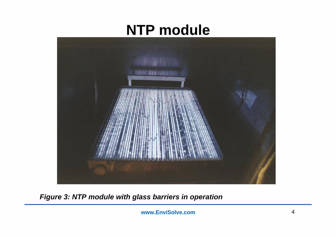
NTP module
Figure 3: NTP module with glass barriers in operation
5www.EnviSolve.com
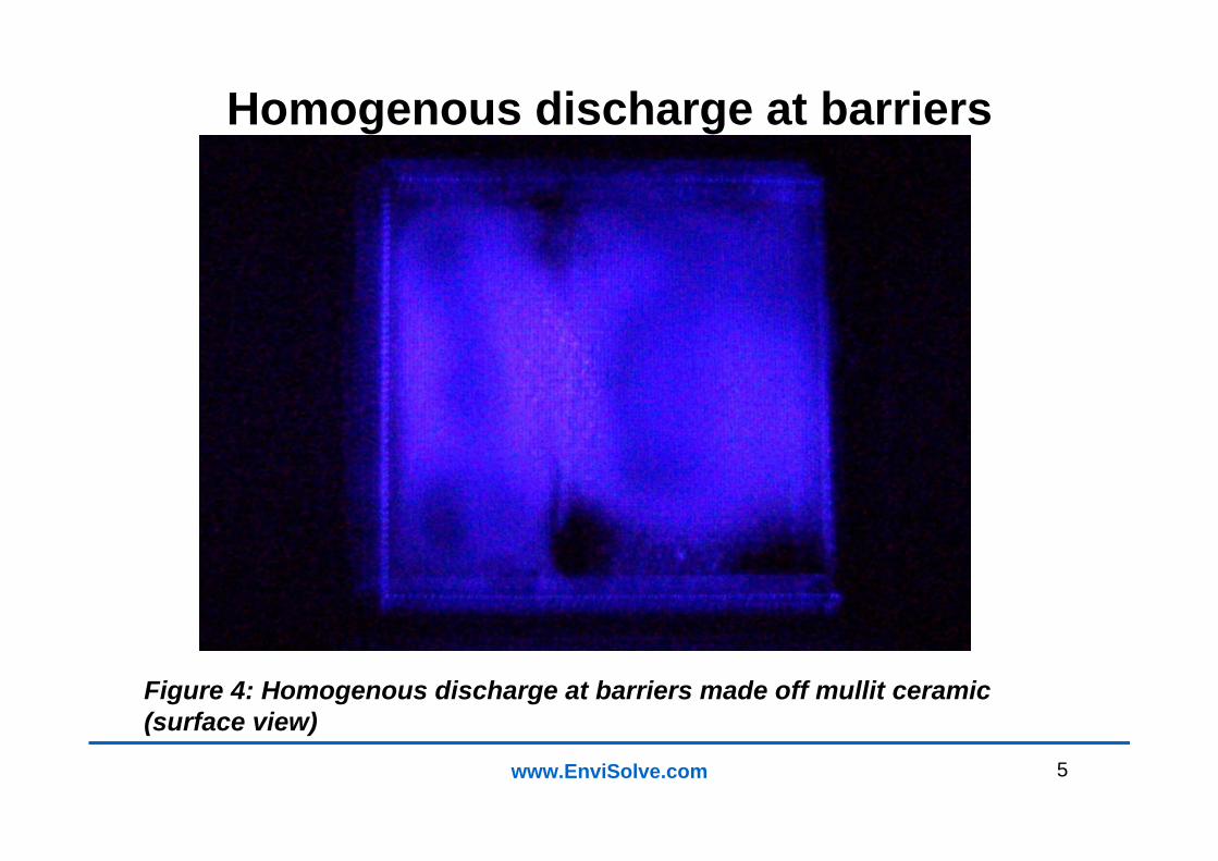
Homogenous discharge at barriers
Figure 4: Homogenous discharge at barriers made off mullit ceramic (surface view)
6www.EnviSolve.com
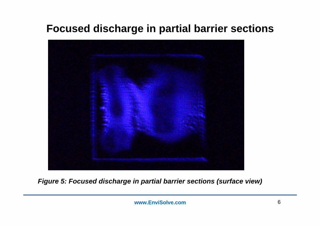
Focused discharge in partial barrier sections
Figure 5: Focused discharge in partial barrier sections (surface view)

7www.EnviSolve.com
Discharge in a plasma module
Figure 6: Discharge in a plasma module with plate barriers (top view)
8www.EnviSolve.com
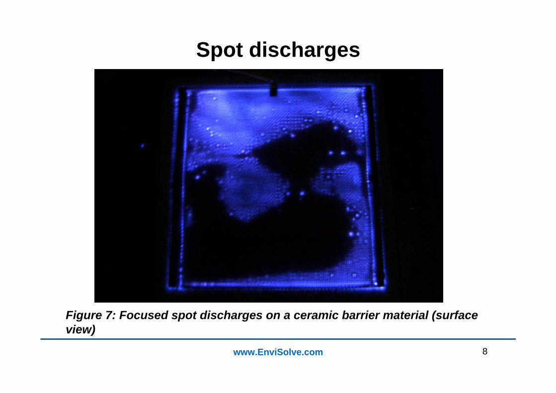
Spot discharges
Figure 7: Focused spot discharges on a ceramic barrier material (surface view)
9www.EnviSolve.com
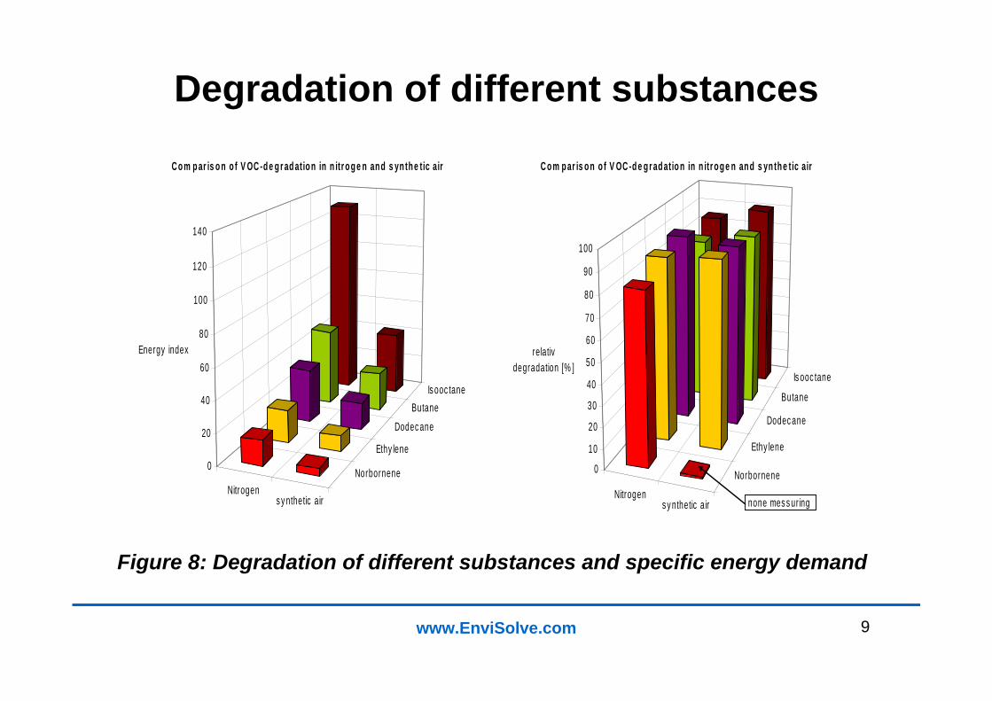
Degradation of different substances
Figure 8: Degradation of different substances and specific energy demand
Is ooc taneButane
Dodec ane
Ethy lene
NorborneneNitrogen
s y nthetic air
0
20
40
60
80
100
120
140
Energy index
C o m p ar is o n o f V OC -d e g r ad atio n in n itr o g e n an d s yn th e tic air
Is ooc tane
Butane
Dodec ane
Ethy lene
NorborneneNitrogen
s y nthetic air
0
10
20
30
40
50
60
70
80
90
100
relativ degradation [% ]
C o m p ar is o n o f V OC -d e g r ad atio n in n itr o g e n an d s yn th e tic air
none mes s uring
10www.EnviSolve.com
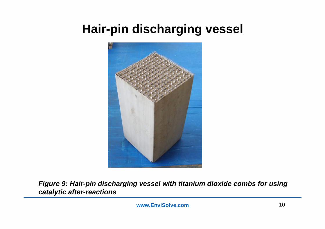
Hair-pin discharging vessel
Figure 9: Hair-pin discharging vessel with titanium dioxide combs for using catalytic after-reactions
11www.EnviSolve.com
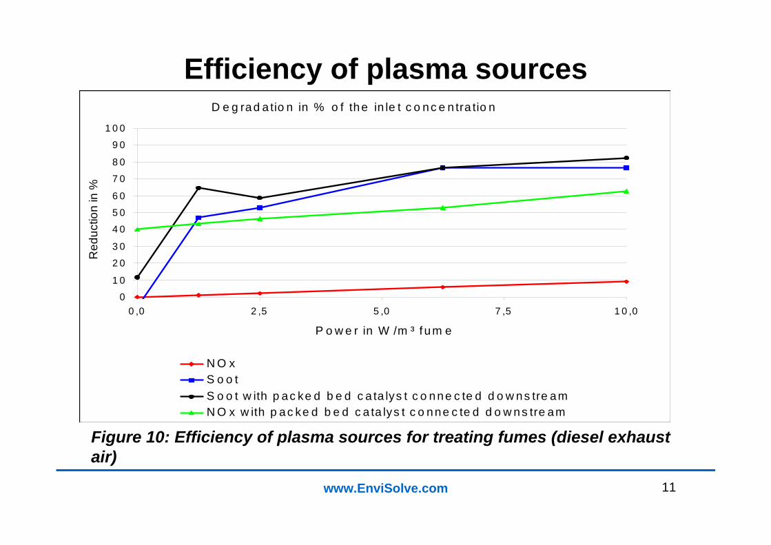
Efficiency of plasma sources
Figure 10: Efficiency of plasma sources for treating fumes (diesel exhaust air)
D e g rad a tio n in % o f the in le t c o nc e n tra tio n
0
1 0
2 0
3 0
4 0
5 0
6 0
7 0
8 0
9 0
1 0 0
0 ,0 2 ,5 5 ,0 7 ,5 1 0 ,0
P o w e r in W /m ³ f um e
Red
uctio
n in
%
N O xS o o tS o o t w ith p ac ke d b e d c a ta lys t c o nne c te d d o w ns tre amN O x w ith p ac ke d b e d c a ta lys t c o nne c te d d o w ns tre am

12www.EnviSolve.com
Catalytic supported NTP plant for 10,000 m³/h of waste air
Figure 11: Catalytic supported NTP plant for 10,000 m³/h of waste air behind flavouring processes for food

13www.EnviSolve.com
Results of the degradation of odour behind oil mills
Figure 12: Results of the degradation of odour behind oil mills (without catalyst)
Odor reduc tion behind o il mills(humid ity approx 95% )
540
1070019000
38000
1
10
100
1000
10000
100000
0 10 20 30 40 50
app lication o f ene rgy [W h/g V O C ]
Odo
r con
cent
ratio
n [O
U/m
³]
14www.EnviSolve.com
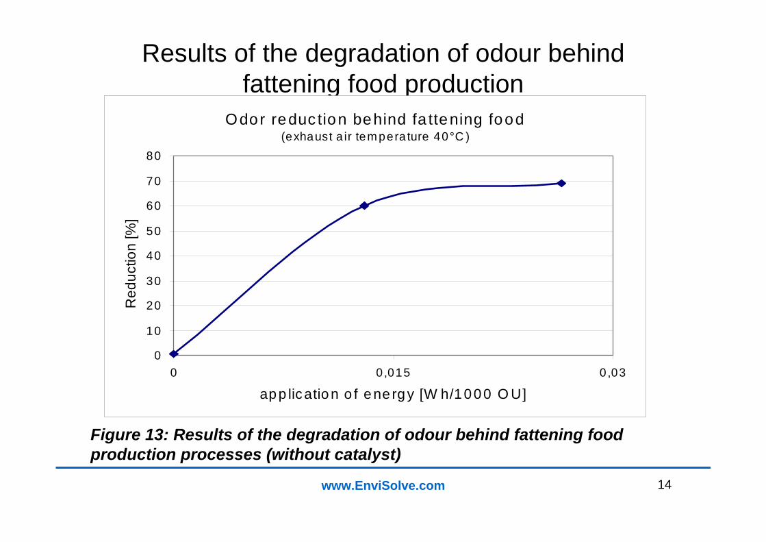
Results of the degradation of odour behind fattening food production
Figure 13: Results of the degradation of odour behind fattening food production processes (without catalyst)
Odor reduc tion behind fa ttening food(exhaust a ir temperature 40°C )
0
10
20
30
40
50
60
70
80
0 0,015 0,03
app lication o f ene rgy [W h/1000 O U]
Red
uctio
n [%
]
15www.EnviSolve.com
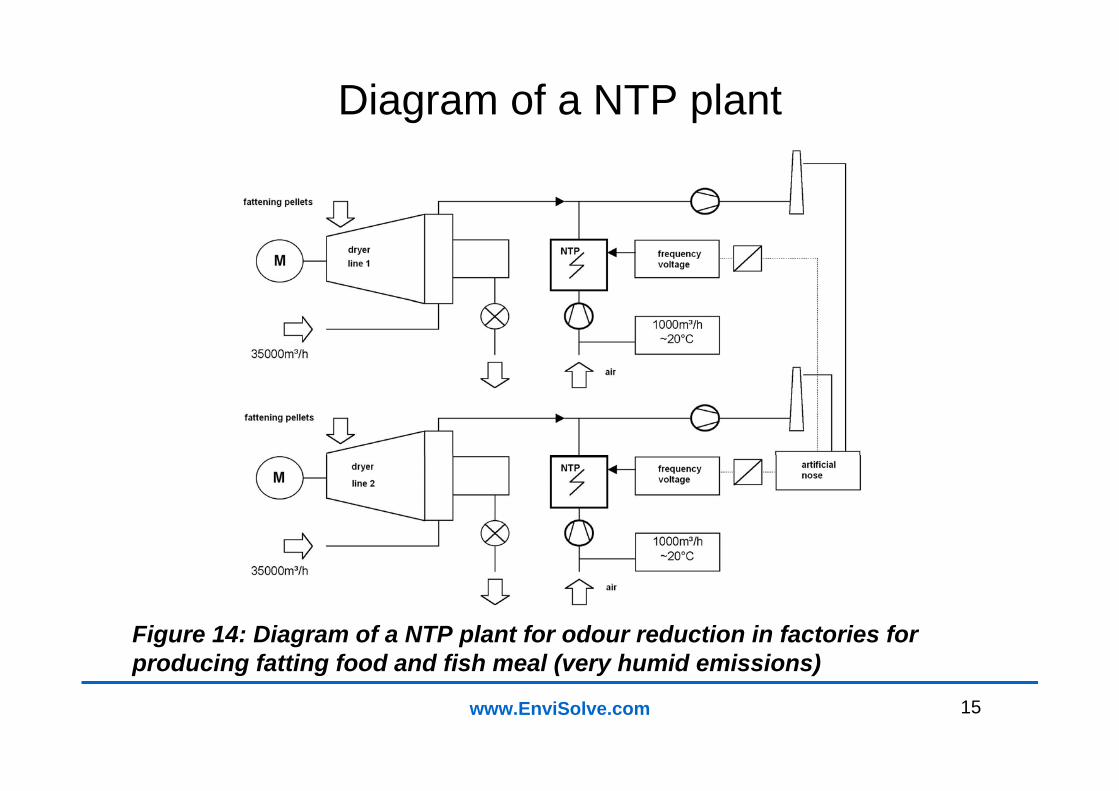
Diagram of a NTP plant
Figure 14: Diagram of a NTP plant for odour reduction in factories for producing fatting food and fish meal (very humid emissions)

16www.EnviSolve.com
Investment- and running costs
Figure 15: Investment- and running cost comparison of waste air purification processes (50,000 m³N/h) for <100 mg VOC/m³ in the flavour processing industry
17www.EnviSolve.com
Thank you for your attention
Rafflenbeul IngenieureVoltastraße 5 63225 Langen
Tel.: 06103 / 30 09 78Fax: 06103 / 28 06 65
E-Mail: [email protected]
Related Documents