199 Non-linear dynamic behaviour of compound planetary gear trains: model formulation and semi-analytical solution A Al-shyyab 1∗ , K Alwidyan 2 , A Jawarneh 1 , and H Tlilan 1 1 Department of Mechanical Engineering, Hashemite University, Zarqa, Jordan 2 Department of Mechatronics Engineering, Hashemite University, Zarqa, Jordan The manuscript was received on 12 November 2008 and was accepted after revision for publication on 3 March 2009. DOI: 10.1243/14644193JMBD197 Abstract: A discrete, non-linear, time-varying, torsional dynamic model of a multi-stage planetary train that is formed by any number of simple planetary stages is proposed in this study. Each planetary stage has a distinct fundamental mesh frequency and any number of plan- ets spaced in any angular positions. The model allows the analysis of the gear train in all possible power flow configurations suitable for various gear drive ratios. It includes periodic variation of gear mesh stiffnesses as well as clearance (backlash) non-linearities that allow tooth separations. Equations of motion for the general case are formulated and solved semi-analytically using a hybrid harmonic balance method (HBM) in conjugate with inverse Fourier transform. Relative mesh displacements along lines of action of individual gear pairs were used as the continuation parameters to pass singular points and ill-conditioned equations in their proximity. At the end, a case study of a two-stage planetary train is used to demonstrate the effectiveness of the model and solution methods. The HBM solutions are compared to those obtained by a direct numerical integration method to assess their accuracy. Keywords: multi-stage planetary gear trains, non-linear dynamics, torsional model, time varying, harmonic balance method, inverse discrete Fourier transform 1 INTRODUCTION Planetary gear sets are widely used in many applica- tions including automotive transmission, rotorcraft, wind and gas turbine gearboxes, as well as other marine and industrial power transmission systems. Planetary gear trains have many advantages over fixed-centre counter-shaft gear systems. The flow of power via multiple-gear meshes increases the power density, helping to reduce the overall size of the gearbox. The axi-symmetric orientation of the planet gears reduces the radial bearings loads and in many cases allowing its central members (sun gear, ring gear, or the planet carrier) to float radially. This reduces the effect of gear and carrier manufactur- ing errors on planet load sharing. Finally, the ability ∗ Corresponding author: Department of Mechanical Engineering, The Hashemite University, Zarqa 13115, Jordan. email: [email protected]; [email protected] of multi-stage planetary sets in providing multiple speed reduction (gear) ratios has been the main reason for their extensive use for automatic trans- mission applications. Compound planetary trains are obtained from a number of single-stage planetary gear sets whose central members are connected accord- ing to a given power flow configuration. Input, out- put, and fixed (stationary) member assignments are made to certain central members to achieve a given gear ratio. Most of the published planetary gear train dynamic models were limited to single-stage planetary gear sets. Early models were of linear time-invariant type (no backlash and constant mesh stiffness) where the eigen solutions and model summation techniques were used to predict the natural modes and the forced response [1–4]. These models were extended to study the neutralization or cancellation of excitations at each gear mesh through proper phasing of the gear meshing by specifying the planet position angles and numbers of teeth of gears [5–7]. JMBD197 © IMechE 2009 Proc. IMechE Vol. 223 Part K: J. Multi-body Dynamics

Welcome message from author
This document is posted to help you gain knowledge. Please leave a comment to let me know what you think about it! Share it to your friends and learn new things together.
Transcript
199
Non-linear dynamic behaviour of compoundplanetary gear trains: model formulation andsemi-analytical solutionA Al-shyyab1∗, K Alwidyan2, A Jawarneh1, and H Tlilan1
1Department of Mechanical Engineering, Hashemite University, Zarqa, Jordan2Department of Mechatronics Engineering, Hashemite University, Zarqa, Jordan
The manuscript was received on 12 November 2008 and was accepted after revision for publication on 3 March 2009.
DOI: 10.1243/14644193JMBD197
Abstract: A discrete, non-linear, time-varying, torsional dynamic model of a multi-stageplanetary train that is formed by any number of simple planetary stages is proposed in thisstudy. Each planetary stage has a distinct fundamental mesh frequency and any number of plan-ets spaced in any angular positions. The model allows the analysis of the gear train in all possiblepower flow configurations suitable for various gear drive ratios. It includes periodic variation ofgear mesh stiffnesses as well as clearance (backlash) non-linearities that allow tooth separations.Equations of motion for the general case are formulated and solved semi-analytically using ahybrid harmonic balance method (HBM) in conjugate with inverse Fourier transform. Relativemesh displacements along lines of action of individual gear pairs were used as the continuationparameters to pass singular points and ill-conditioned equations in their proximity. At the end,a case study of a two-stage planetary train is used to demonstrate the effectiveness of the modeland solution methods. The HBM solutions are compared to those obtained by a direct numericalintegration method to assess their accuracy.
Keywords: multi-stage planetary gear trains, non-linear dynamics, torsional model, timevarying, harmonic balance method, inverse discrete Fourier transform
1 INTRODUCTION
Planetary gear sets are widely used in many applica-tions including automotive transmission, rotorcraft,wind and gas turbine gearboxes, as well as othermarine and industrial power transmission systems.Planetary gear trains have many advantages overfixed-centre counter-shaft gear systems. The flow ofpower via multiple-gear meshes increases the powerdensity, helping to reduce the overall size of thegearbox. The axi-symmetric orientation of the planetgears reduces the radial bearings loads and in manycases allowing its central members (sun gear, ringgear, or the planet carrier) to float radially. Thisreduces the effect of gear and carrier manufactur-ing errors on planet load sharing. Finally, the ability
∗Corresponding author: Department of Mechanical Engineering,
The Hashemite University, Zarqa 13115, Jordan.
email: [email protected]; [email protected]
of multi-stage planetary sets in providing multiplespeed reduction (gear) ratios has been the mainreason for their extensive use for automatic trans-mission applications. Compound planetary trains areobtained from a number of single-stage planetary gearsets whose central members are connected accord-ing to a given power flow configuration. Input, out-put, and fixed (stationary) member assignments aremade to certain central members to achieve a givengear ratio.
Most of the published planetary gear train dynamicmodels were limited to single-stage planetary gearsets. Early models were of linear time-invariant type(no backlash and constant mesh stiffness) where theeigen solutions and model summation techniqueswere used to predict the natural modes and the forcedresponse [1–4]. These models were extended to studythe neutralization or cancellation of excitations at eachgear mesh through proper phasing of the gear meshingby specifying the planet position angles and numbersof teeth of gears [5–7].
JMBD197 © IMechE 2009 Proc. IMechE Vol. 223 Part K: J. Multi-body Dynamics
200 A Al-shyyab, K Alwidyan, A Jawarneh, and H Tlilan
The experimental and theoretical studies on singleand multi-mesh, counter-shaft spur gear dynam-ics [8–11] clearly indicate that spur gears shouldbe modelled as non-linear systems having periodi-cally varying parameters, pointing to a major short-coming of the above models. There are a very fewpublished non-linear time-varying planetary gear setdynamic models. In one such study, Kahraman [12]investigated the impact of manufacturing errors ondynamic planet load sharing, but did not focus onthe impact of the non-linearities and time-varyingparameters. Tao and Yan [13] investigated the fre-quency response of non-linear planetary set withmultiple clearances by using single-term harmonicbalance method (HBM) and focusing only on a sin-gle power flow configuration, in which the ring gearwas held stationary. Recently, Al-shyyab and Kahra-man [14] developed a torsional single-stage non-linear dynamic model of a simple planetary gearset and provided a semi-analytical forced responsesolution by using multi-term HBM and showed thatthese HBM solutions compared well to the numer-ical integration (NI) and deformable body finite-element-based solutions [15]. Also, a recent studyby Inalpolat and Kahraman [16] provided a com-prehensive formulation for dynamics modelling ofcompound planetary sets. Their model was generalin many aspects as it included any number of plan-etary gear stages, any number of planets in eachgear stage, and any power flow configurations. It alsoincluded complex compound planetary gear typessuch as double-planet and Ravigneaux arrangements.However, their linear time-invariant formulation didnot include time varying mesh stiffnesses and gearbacklash.
This study proposes a general non-linear time-varying model of a multi-stage planetary gear train.This model is designed to handle any number of plan-etary stages and any kinametic configurations. Eachgear stage is formed by simple planetary gear set hav-ing any number of planets positioned in any spacingconfiguration. The tooth separations induced by gearbacklash and parametric variation of gear mesh stiff-nesses due to fluctuation of number of loaded toothpair are both included in this model. Equations ofmotion are presented for a general case where connec-tions between different gear stages are done through anumber of torsional coupling stiffnesses. HBM is usedto obtain the corresponding set of non-linear alge-braic equations that are solved numerically to find theforced response vibration amplitudes. Gear mesh dis-placements along the line of action of gear pairs areintroduced as the continuation parameters to facili-tate continuous solutions through the singular points.Effectiveness of the model and the solution methodis demonstrated at the end using an example geartrain formed by two stages of planetary gear sets. Theaccuracy of the HBM solutions are also demonstrated
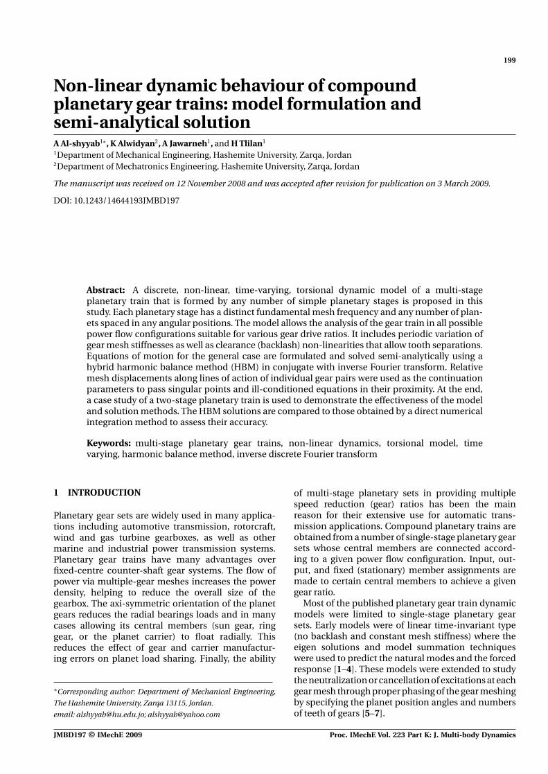
Fig. 1 Stick diagram of the three-stage segment repre-sentative of a general single-planet multi-stageplanetary set; arbitrary solid line connections areeither representative of permanent or clutch cou-plings. Dash-dot line is the axis of rotation. Ti
and To are representatives of input and outputtorques, respectively
through comparisons to the corresponding direct NIsolutions.
2 DYNAMIC MODEL
A schematic of a three-stage segment of a d-stage com-pound gear train is shown in Fig. 1. A particular stagen (n = 1 to d) comprises three central elements, thesun gear (s(n)), the ring gear (r (n)), and carrier (c(n)) aswell as n(n)
p number of planets (p(n)
i ). The planets ofeach stage are free to rotate with respect to their com-mon carrier, while the central elements of any stageare candidates for being an input, output, or reactionmember. Multiple stages can be connected in differentways via a proper coupling (a central member of stage-n is connected to a central member of stage-m througha torsional spring) representing a permanent or clutchconnection. In Fig. 1, an example set of permanent orclutch stage couplings are shown in solid lines, whilethe model allows any user defined set of couplings.
The torsional dynamic model of the planetary gearset of stage-n is shown in Fig. 2. This model is similarto the one proposed by Al-shyyab and Kahraman [14]with the exception of torsional springs of stiffnessesk(n,m)
j� added here to represent coupling of the cen-tral member j of stage-n with the central member �
of stage-m. This discrete model employs a number ofsimplifying assumptions as discussed in detail in ref-erence [14]. The central elements s(n), r (n), and c(n) areconstrained by torsional linear springs of stiffnessesk(n)
st , k(n)rt , and k(n)
ct , respectively. A particular centralmember is held stationary by assigning a very largeconstraint stiffness value to it. Likewise, a zero valuefor the constraint stiffness indicates that this cen-tral member is not connected to the housing. Themagnitudes of the stage coupling stiffnesses k(n,m)
j� arechosen to represent the torsional stiffness of the actual
Proc. IMechE Vol. 223 Part K: J. Multi-body Dynamics JMBD197 © IMechE 2009
Non-linear dynamic behaviour of compound planetary gear trains 201
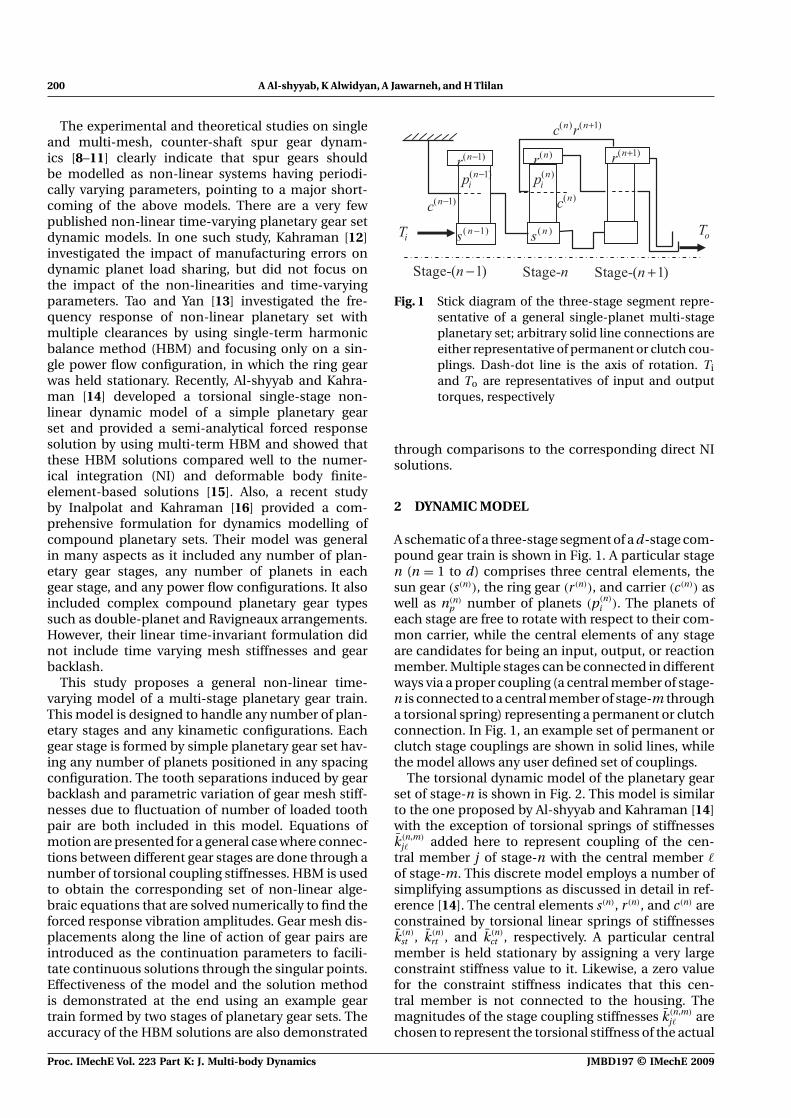
Fig. 2 Dynamic model of a multi-stage planetary gear set
physical connection in a given power flow arrange-ment. Here k(n,m)
j� determines the level of couplingbetween the two central members it connects. Eachgear body i (i = s(n), r (n), c(n), p1(n), . . . , pn(n)
p ) is mod-elled as a rigid disc of polar mass moment of inertia I (n)
i ,radius r (n)
i , and torsional displacement θ(n)
i . Here, θ(n)
i isthe vibrational component of the displacement aboutthe nominal rigid body rotation of the gear. Planets arelocated at radius r (n)
c at arbitrary spacing angles ψ(n)
i
defined positive in the counter-clockwise direction.External torques T (n)
j ( j = s(n), r (n), c(n)) are applied tothe central members that are identified as the inputand output members of the gear train.
The mesh jpi(n) of gear j (s(n) or r (n)) with a planetpi(n) is represented by a periodically time-varying stiff-ness parameter k(n)
jpi (t) subjected to a piecewise linearbacklash function g (n)
jpi that includes a clearance ofamplitude 2b(n)
jpi . A periodic displacement functione(n)
jpi (t) is applied along the line of action to accountfor intentional gear tooth profile modifications as wellas deviations because of surface wear and manufac-turing errors. Losses at the same lubricated gear meshinterface is represented by constant viscous damp-ing coefficient c(n)
jpi . Here, for each stage, it is assumedthat all planets pi(n) and their respective meshes with
gear j (s(n) or r (n)) are identical, i.e. k(n)
jpi (t), e(n)
jpi (t), b(n)
jpi ,g (n)
jpi , and c(n)
jpi are the same for all jpi(n) meshes, exceptthe phase angles of k(n)
jpi (t) and e(n)
jpi (t), which differbecause of the particular planet phasing conditionconsidered.
2.1 Equations of motions
Non-dimensional equations of motion for the plane-tary gear set at stage-n are given as (n, m ∈ [1, d],j ∈ [s, r], � ∈ [s, r, c], i ∈ [1, n(n)
p ])
θ(n)
cpi (t) + θ (n)c (t) + 2ζ (n)
sc ω(n)sc p(n)
spi (t) − 2ζ (n)rc ω(n)
rc p(n)
rpi (t)
+ [ω(n)sc ]2κ
(n)
spi (t)g (n)
spi (t) − [ω(n)rc ]2κ
(n)
rpi (t)g (n)
rpi (t) = 0(1a)
θ(n)
j (t) + 2ζ(n)
jj ω(n)
jj
np∑i=1
p(n)
jpi (t) + [ω(n)
j ]2θ(n)
j (t)
+ [ω(n)
jj ]2
np∑i=1
κ(n)
jpi g (n)
jpi (t) +d∑
m=1m �=n
[ω(n,m)
j� ]2(θ(n)
j − θ(m)
� )
= f (n)
j (t) (1b)
JMBD197 © IMechE 2009 Proc. IMechE Vol. 223 Part K: J. Multi-body Dynamics
202 A Al-shyyab, K Alwidyan, A Jawarneh, and H Tlilan
θ (n)c (t) + I (n)
p
I (n)ce
np∑i=1
θ(n)
cpi (t)−2ζ (n)sc ω(n)
sc
np∑i=1
p(n)
spi (t)
− 2ζ (n)rc ω(n)
rc
np∑i=1
p(n)
rpi (t) + [ω(n)c ]2θ(n)
c (t)
− [ω(n)sc ]2
np∑i=1
κ(n)
spi (t)gspi(t) − [ω(n)rc ]2
np∑i=1
κ(n)
rpi (t)g (n)
rpi (t)
+d∑
m=1m �=n
[ω(n,m)
cl ]2(θ (n)c − θ
(m)
l ) = f (n)c (t) (1c)
The total number of degrees of freedom (and hence thenumber of equations of motion) of a d-stage planetarytrain in this model is (3d + ∑d
n=1 n(n)p ). These equations
are similar to those proposed by Al-shyyab and Kahra-man [14], except the last term on the left-hand sideof the equations of motion of the central elements isadded to account for the coupling terms. Here, an over-dot means derivative with respect to time, I (n)
ce = I (n)c +
n(n)p (I (n)
p + r2c m(n)
p ) is the equivalent mass moment ofinertia of the carrier assembly of stage-n, and m(n)
p =∑n(n)p
i=1 m(n)
pi , where m(n)
pi is the mass of planet p(n)
i . Abso-lute rotations θ(n)
s , θ(n)r , θ(n)
c , and the relative rotationsof planets with respect to the carrier θ
(n)
cpi (t) = θ(n)
pi (t) −θ(n)
c (t) are used as the coordinates. In these equa-tions, p(n)
jpi are the relative gear mesh displacementsdefined as
p(n)
jpi (t) = δjr (n)p θ
(n)
jpi (t) + r (n)
j [θ(n)
j (t) − θ(n)c (t)] − e(n)
jpi (t)
δj ={
1 j = s
−1 j = r(2a)
and the piecewise-linear backlash functions aredefined as
g (n)
jpi [p(n)
jpi (t)] =
⎧⎪⎪⎨⎪⎪⎩
p(n)
jpi (t) − b(n)
jp , p(n)
jpi (t) > b(n)
jp
0, |p(n)
jpi (t)| < b(n)
jp
p(n)
jpi (t) + b(n)
jp , p(n)
jpi (t) < −b(n)
jp
(2b)
Non-dimensional parameters of equations (1) and (2)were obtained by using a characteristic length ba andfrequency ωa, such that
r (n)
i = r (n)
i
ba(3a)
p(n)
jpi (t) = p(n)
jpi (t)
ba(3b)
e(n)
jpi (t) = e(n)
jpi (t)
ba(3c)
b(n)
jp = b(n)
jp
ba(3d)
κ(n)
jpi (t) = k(n)
jpi (t)
k(n)
jp
= 1 + k(n)
jp (t)
k(n)
jp
(3e)
t = ωat (3f)
Here, an overbar denotes a dimensional quantity, andk(n)
jp and k(n)
jpi (t) are dimensional mean and alternatingcomponents of stiffness of the jp mesh of stage-n.Dimensionless quantities ω
(n)
ij , ζ(n)
jj , f (n)
j (t), and ω(n,m)
j�
are defined in Appendix 2.
3 STEADY-STATE RESPONSE USING THEMULTI-TERM HBM
The κ(n)
jpi (t) terms ( j = s, r, n = 1, 2, . . . , d) in equa-tion (1) are periodically time varying. These excitationshave a dimensionless fundamental frequency (n) =(n)
cp Z (n)p /ωa, where (n)
cp and Z (n)p are the angular velo-
city of the planets with respect to their carrier andthe number of planet teeth, respectively. Since eachstage has its own distinct fundamental tooth passfrequency (n), frequencies of all meshes can beprescribed simultaneously by one common param-eter such that μn = (n), μm = (m), . . . , =μd(d) where μn, μm, . . . , μ� are integer numbers. Withthese definitions, stiffnesses κ
(n)
jpi (t) can be written inFourier series form as (j ∈ [s, r], n ∈ [1, 2, . . . , d], i ∈[1, 2, . . . , n(n)
p ])
κ(n)
jpi (t) = 1 +H∑
h=1
[κ jpi(n)
2h cos(ht) + κjpi(n)
2h+1 sin(ht)]
(4a)
where H is the number of harmonic terms sufficientto describe the periodic stiffness function. In orderto reveal the effects of interactions of all mesh stiff-ness harmonic components due to mesh stiffnessphasing angles, H should be equal to or larger thanμnn(n)
p . The magnitudes κjpi(n)
2h and κjpi(n)
2h+1 of each meshstiffness of fundamental frequency (n) = μn aredefined as
κjpi(n)
2h
=
⎧⎪⎪⎪⎨⎪⎪⎪⎩
2
hπC (n)
jp
sin[hπ(C (n)
jp − Z (n)
jp )]× cos(�jpi(n)
h + �(n,m)), h/μn = integer
0, h/μn �= integer
(4b)
Proc. IMechE Vol. 223 Part K: J. Multi-body Dynamics JMBD197 © IMechE 2009
Non-linear dynamic behaviour of compound planetary gear trains 203
κjpi(n)
2h+1
=
⎧⎪⎪⎪⎨⎪⎪⎪⎩
−2
hπC (n)
jp
sin[hπ(C (n)
jp − Z (n)
jp )]× sin(�
jpi(n)
h + �(n,m)), h/μn = integer
0, h/μn �= integer
(4c)
�jpi,(n)
h = hZ (n)
j ψ(n)
i + hγ (n)sr (4d)
where C (n)
jp is the contact ratio of the gear meshjpi(n). �
jpi(n)
h is the phase angle of the h-th harmonicterm of the stiffness of the same mesh jpi(n), (i �= 1)
defined relative to the same harmonic order of thefirst mesh jp1(n). Here, without loss of generality, phas-ing of all harmonic components of stiffness κ
(n)
sp1(t) ofmesh sp1(n) are taken as the reference. Here, the posi-tioning angle of the first planet is ψ
(n)
1 = 0 and thephasing angle is �
sp1,(n)
h = 0. For equally spaced plan-ets, ψ
(n)
i = 2π(i − 1)/n(n)p , (i �= 1). Parameters Z (n)
j andγ (n)
sr are the number of teeth of gear j and phaseangle between stiffnesses of meshes sp1(n) and rp1(n),respectively. Finally, �(m,n) is defined as the phasingangle between stiffness of the reference mesh sp1(n)
of stage-n and that of stage-m. Therefore, phasingof all mesh stiffnesses can be defined with respectto a single reference mesh, defined here as sp1(1).Stage coupling phasing �(m,n) has no geometric lim-itations, for permanent stage connections its valuecan be chosen carefully to achieve desired minimumstiffness excitations. On the other hand, for a con-nection through a clutch, its value is random, as itcan take a different value each time the clutch isengaged.
Similar to stiffnesses, periodic displacement excita-tions defined at each mesh to account for the manu-facturing deviations and static transmission errors.They contain the same harmonic orders and phasingrelationships as κ
(n)
jpi (t) and can be written in Fourierseries form as
e(n)
jpi (t) = Ejpi(n)
1 +N∑
n=1
[Ejpi(n)
2n cos(nt)
+ Ejpi(n)
2n+1 sin(nt)] (5)
where Ejpi(n)
2h = Ejpi(n)
2h+1 = 0 for h/μn �= integer. Likewise,the external excitations that represent any periodictorque pulsations are also written in the same form
f (n)
j (t) = f (n)
j +L∑
�=1
[f j(n)
2� cos(�t) + f j(n)
2�+1 sin(�t)]
(6)
Periodic solutions of equation (1) are assumed as (a ∈[s, c, r, cp1, cp2, . . . , cpn(n)
p ], (n ∈ [1, 2, . . . , d])
θ (n)a (t) = ua(n)
1 +K∑
k=1
[ua(n)
2kηcos(kt)
+ ua(n)
2kη+1 sin(kt)] (7)
where η is the sub-harmonic index, ua(n)
j is the ampli-tude of the solution harmonic contents of member a,and K is the number of harmonic terms consideredin the assumed solution. The same way, the linearmesh displacement along the line of action p(n)
jpi (t) iswritten as
p(n)
jpi = Pjpi(n)
1 +K∑
k=1
[Pjpi(n)
2kηcos(kt) + Pjpi(n)
2kη+1 sin(kt)](8a)
with
Pjpi(n)
1 = δjrpucpi(n)
1 + rj(uj(n)
1 − uc(n)
1 ) − Ejpi(n)
1 (8b)
Pjpi(n)
2kη= δjrpucpi(n)
2kη+ rj(uj(n)
2kη− uc(n)
2kη) − Ejpi(n)
2(k/η)(8c)
Pjpi(n)
2kη+1 = δjrpucpi(n)
2kη+1 + rj(uj(n)
2kη+1 − uc(n)
2kη+1) − Ejpi(n)
2(k/η)+1
(8d)
Before enforcing a harmonic balance, the backlashfunctions g (n)
jpi (t) should be written in the same formas well
g (n)
jpi = vjpi(n)
1 +K∑
k=1
[vjpi(n)
2kηcos(kt) + vjpi(n)
2kη+1 sin(kt)]
(9)
By dividing the solution period T into Q subintervals(�T = T /Q), and using inverse discrete Fourier trans-forms, the amplitudes vjpi(n)
k can be obtained [11]. Withthese definitions, the product κ
(n)
jpi (t)g (n)
jpi (t) is derivedfrom equations (5) and (10) as
κ(n)
jpi (t)g (n)
jpi (t) = ϕjpi(n) +K∑
k=1
[C jpi(n)
k cos(kt)]
+N∑
k=1
[Djpi(n)
� sin(kt)] (10)
where C jpi(n)
k , Djpi(n)
k , and ϕjpi(n) are given in Appendix 2.Substituting equations (6) to (10) into equation (1),
and enforcing harmonic balance, a set of generic non-linear algebraic equations is obtained in the form (� ∈[1, 2K + 1], j ∈ [s, r, c, cpi], m, n ∈ [1, 2, . . . , d])
S(n)(uj(n)
� , ui(m)
� , ) = 0 (11)
where elements of vector S(n) are given in Appendix 2.The number of equations contained by S(n) for each
JMBD197 © IMechE 2009 Proc. IMechE Vol. 223 Part K: J. Multi-body Dynamics
204 A Al-shyyab, K Alwidyan, A Jawarneh, and H Tlilan
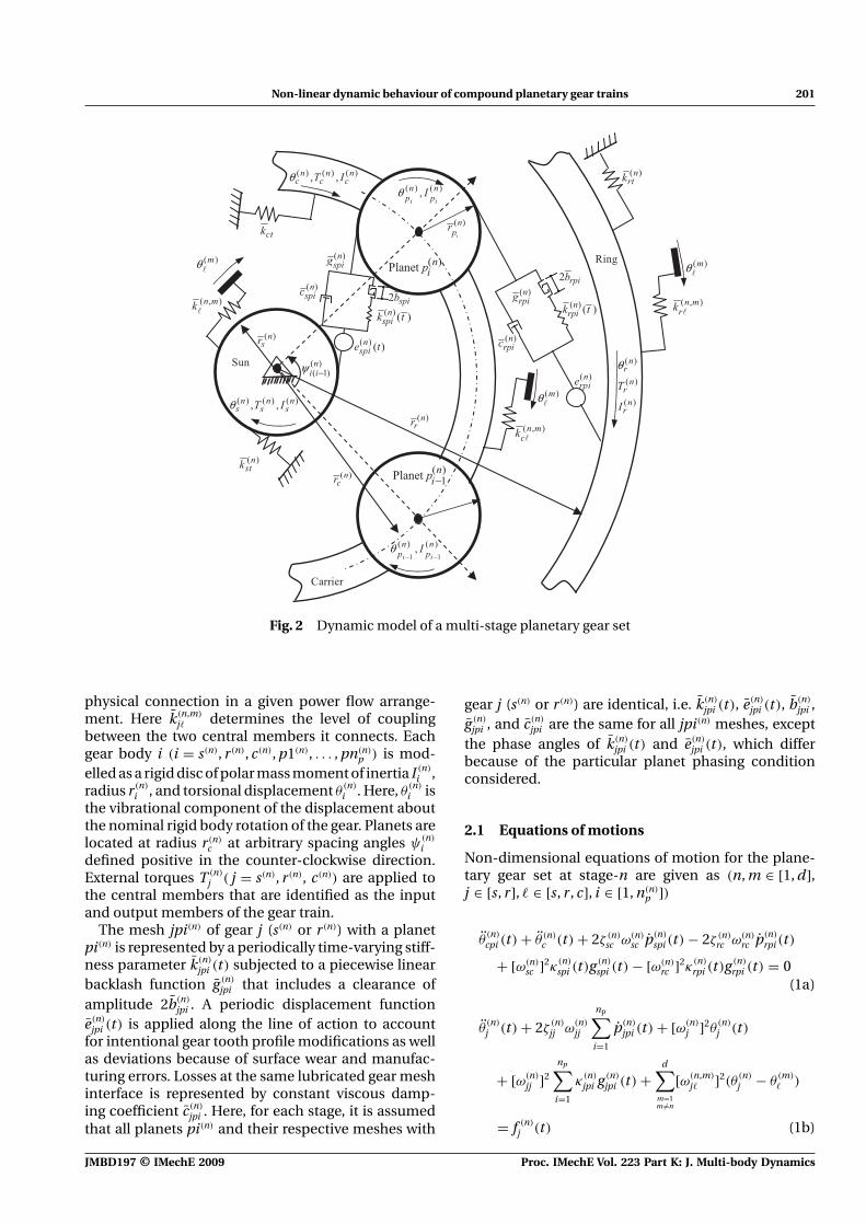
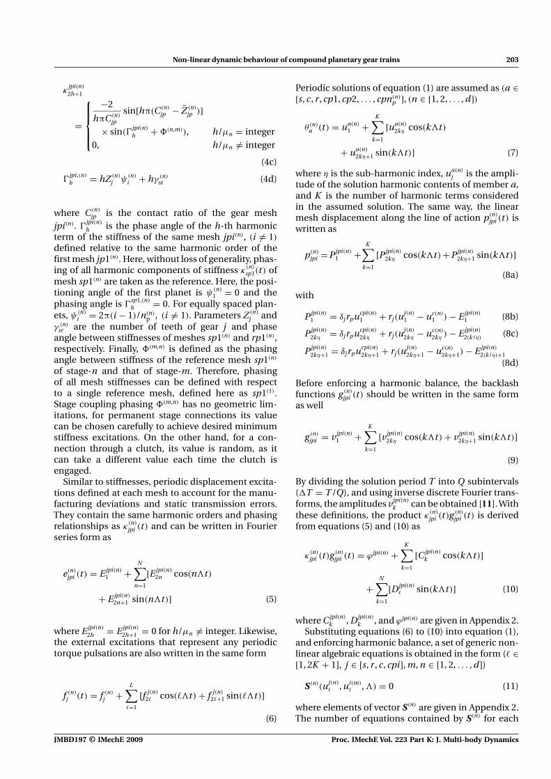
Fig. 3 Two-stage planetary set and sequence of clutchrelease and activation. X means clutch activated
stage and for a gear train with d stages are (2K +1)(n(n)
p + 3) and (2K + 1)(∑d
n=1 n(n)p + 3d), respectively.
Therefore, the total number of algebraic equations isequal to the number of unknown motion amplitudesdefined by the vector U = [us(1), ur(1), ucp1(1), ucpnp(1), . . . ,us(d), ur(d), ucp1(d), ucpnp(d)]T. Here, uj(n) = [uj(n)
1 , . . . , uj(n)
2� ,uj(n)
2�+1]T(� ∈ [1, K ]) is the torsional displacement ampli-tudes of member j of stage-n. These amplitudes can beobtained by prescribing a control parameter and solv-ing equation (12) iteratively using Newton’s method.However, singularities at bifurcation points as wellas ill-conditioned nature of the equations aroundthese points impede the solution curve to be followedcontinuously. Hence, other continuation parametersare needed. As the relative gear mesh displacementsPjp1(n)
k combine all motion displacement amplitudesuj(n)
� , its use as a control parameter is advisable here.Accordingly, each displacement Pjp1(n)
k is defined asan independent parameter uk , (uk = Pjp1(n)
k ) and thefollowing equations are appended to equation (12)(� ∈ [1, 2K + 1])
Srp1(1)
q1+� = uq1+� − Prp1(1)
q1+�
Srp1(2)
q2+� = uq2+� − Prp1(2)
q2+� , . . . , Srp1(d)
qd+� = uqd+� − Prp1(d)
qd+�
(12a)
Ssp1(1)
qd+1+� = uqd+1+� − Psp1(1)
qd+1+�
Ssp1(2)
qd+2+� = uqd+2+� − Psp1(2)
qd+2+�, . . . , Ssp1(d)
q2d + � = uq2d+� − Psp1(d)
q2d+�
(12b)
In addition, the following equation is added to definethe control parameter
S� = u� − , u� = (12c)
Here, q1 = (2K + 1)[3d + ∑di=1 n(i)
p ], qi = qi−1 + (2K +1), i = (2, 3, . . . , 2d), and � = q2d + � + 1 is the totalnumber of algebraic equations and the elementsof the modified unknown parameter vector U ∗ =[U , uq1+1, . . . , uq1+�, . . . , uqd+�, . . . , uqd+1+�, . . . , uq2d
+ �,. . . , u�]T. Starting the solution scheme with u� as acontrol parameter and as its prescribed value, thesolution scheme proceeds until a bifurcation pointimpedes the continuation of the solution. At thispoint, switching to a mesh displacement amplitudeul+�, (ul+� = Pjp1(n)
l+�, l ∈ [q1, q2, . . . , q2d]) with the max-
imum gradient ∂ul+�/∂u� as a control parameterensured the continuation of the solution. Also, theconvergence of the first point of the non-linear solu-tion curve can be guaranteed using concepts ofhomotopy. The first point of the solution curve canbe obtained by first considering a linear versionof equation (12) with b(n)
jpi = 0 and approaching thenon-linear one (b(n)
jpi �= 0) gradually.
4 TWO-STAGE PLANETARY SET CASE STUDY
As a case study, two-stage single-planet planetary geartrain shown in Fig. 3 will be considered. This gear trainis composed of clutches, permanent stage couplings orconnections c(1)r (2) and c(2)r (1), planets p(n)
i , sun gearss(n) and ring gears r (n), as well as planet carriers c(n).The output torque To is applied to connection c(2)r (1)
permanently. Therefore, power flow configurations ofthe first, second, third, and fourth gear ratios can beobtained by changing central members assignmentsas input, reaction, or free to rotate members via propersequence of clutch release and activation as shownin Fig. 3.
The parameters of the example gear train of Fig. 3 arelisted in Table 1. Each stage is formed by four equallyspaced planets (n(n)
p = 4, ψ(n)
i = 2π(i − 1)/4). Dimen-sionless stiffness amplitudes κ
jpi(n)
h , (h/μn �= 0) are
Table 1 Parameters of the study case two-stage planetary train
First stage Second stage
Parameter Sun, s(1) Planet, p(1) Ring, r(1) Sun, s(2) Planet, p(2) Ring, r(2)
Number of teeth 30 28 70 44 18 80Module (mm) 1.5 1.5Pressure angle (◦) 21.3 21.3
Proc. IMechE Vol. 223 Part K: J. Multi-body Dynamics JMBD197 © IMechE 2009
Non-linear dynamic behaviour of compound planetary gear trains 205
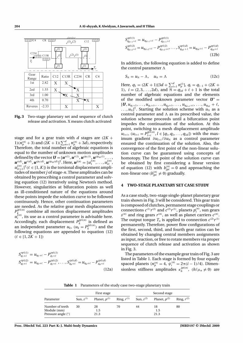
Table 2 Natural frequencies and mode shapes [kHz]
Natural frequencies
ω1 ω2 ω3 ω3 ω3 ω4 ω4 ω4 ω5 ω6 ω7 ω8
Member 3.88 8.60 9.15 9.15 9.15 10.41 10.41 10.41 12.14 14.98 38.10 43.91
θ cp1(1) −0.85 0.45 0 0 0 1 −0.01 0 −0.36 0.38 −0.38 −0.01θ cp2(1) −0.85 0.45 0 0 0 −0.34 −0.5 1 −0.36 0.38 −0.38 −0.01θ cp3(1) −0.85 0.45 0 0 0 −0.33 −0.5 −0.5 −0.36 0.38 −0.38 −0.01θ cp4(1) −0.85 0.45 0 0 0 −0.33 1 −0.5 −0.36 0.38 −0.38 −0.01θ s(1) 1 −0.86 0 0 0 0 0 0 1 1 −0.12 0θ r(1) −0.49 −0.29 0 0 0 0 0 0 0.68 −0.06 0.02 −0.26θ c(1) 0.09 −0.03 0 0 0 0 0 0 −0.44 −0.01 1 0.06θ cp1(2) 0.36 1 −0.58 −0.98 −0.32 0 0 0 0.75 0.02 0.06 −0.27θ cp2(2) 0.36 1 1 −0.24 1 0 0 0 0.75 0.02 0.06 −0.27θ cp3(2) 0.36 1 −0.57 0.22 −0.32 0 0 0 0.75 0.02 0.06 −0.27θ cp4(2) 0.36 1 0.15 1 −0.37 0 0 0 0.75 0.02 0.06 −0.27θ s(2) 0 0 0 0 0 0 0 0 0 0 0 0θ r(2) 0.12 0.04 0 0 0 0 0 0 −0.8 −0.04 −0.46 −0.04θ c2(2) −0.39 −0.27 0 0 0 0 0 0 0.51 −0.06 −0.16 1
estimated for gear contact ratios of C (1)sp = 1.25, C (1)
rp =1.93, C (2)
sp = 1.1, and C (2)rp = 1.95. The mean mesh stiff-
ness values are k(1)
spi = 4.5(10)8, k(1)
rpi = 5.1(10)8, k(2)
spi =4.1(10)8, and k(2)
rpi = 4.4(10)8 N/m. Torsional stiffness(k(n)
tj ) constraints for reaction (fixed) members weretaken as 1010 N m/rad, while other free-to-rotate
members were constrained with very small stiffnesses(k(n)
tj ∼ 102 N m/Rad). Similarly, if member j of stage-1 couples member � of stage-2, then the stiffness ofthe stage coupling k(1,2)
j� = 108 N m/rad, otherwise itsvalue is zero. All coupling stiffnesses are taken to bethe same here. The half backlash values b(n)
jp for all
Fig. 4 (a) First-stage r.m.s mesh force amplitude against mesh tooth pass frequency (1). (––)linear HBM solutions (ba = 0), (�) NI solutions. (b) Second-stage r.m.s mesh force ampli-tude against mesh tooth pass frequency (1). (––) linear HBM solutions (ba = 0), (�) NIsolutions
JMBD197 © IMechE 2009 Proc. IMechE Vol. 223 Part K: J. Multi-body Dynamics
206 A Al-shyyab, K Alwidyan, A Jawarneh, and H Tlilan
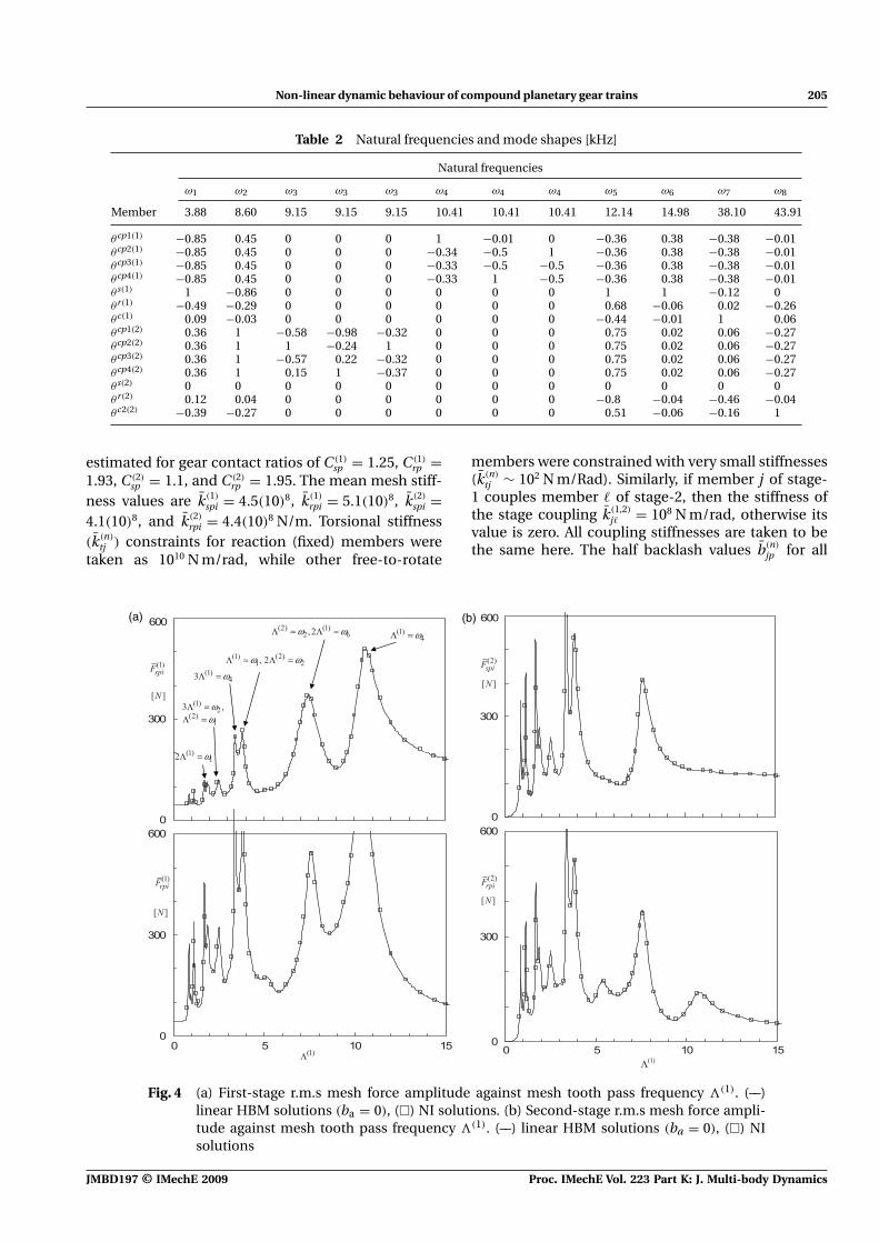
Fig. 5 (a) First-stage r.m.s mesh force amplitude against mesh tooth pass frequency (1). (––)Non-linear (ba = 0.05 mm) and (· · · · · · ) linear (ba = 0) HBM solutions, (�) NI solutions.(b) Second-stage r.m.s mesh force amplitude against mesh tooth pass frequency (1). (––)Non-linear (ba = 0.05 mm) and (· · · · · · ) linear (ba = 0)HBM solutions, (�) NI solutions
meshes are assumed to be 0.05 mm and character-istic quantities ba and ωa are taken as 0.1 mm and1000 rad/s, respectively.
The ratio of mesh tooth pass frequency of the secondstage to that of the first stage (μ2/μ1) is given by
∣∣∣∣μ2
μ1
∣∣∣∣ =∣∣∣∣∣
(2)cp Z (2)
p
(1)cp Z (1)
p
∣∣∣∣∣ = Z (2)r
Z (1)r
= 87
(13)
Accordingly, μ1 = 7 and μ2 = 8 were used, where (n)
j
is the absolute nominal rotational speed of mem-ber j, (n)
cp is the relative nominal speed of theplanet p(n)
i with respect to its holding carrier, andZ (n)
j is the number of teeth of gear j. Gear meshdamping ratios ζ
(n)
ij are approximated using damping
coefficients c(n)
ij = 2ζ
√m(n)
ij k(n)
ij correspond commonvalue of damping ratio for gear meshes ζ = 0.04 [16],where m(n)
ij is the equivalent mass of elements iand j [12].
Equations of motion for first gear ratio configurationwere solved using the HBM method and comparedwith the NI integration results. For the second andfourth gear ratio configurations, meshes of the firststage were unloaded rendered the compound set as
a single-stage set studied earlier by Al-shyyab andKahraman [14]. Furthermore, the third gear drivebears no parametric excitations as the planetary setmembers locked together and rotates as a single block,(n)
cp = 0. Hence, results and analysis of this case studyhereafter are limited for first gear ratio configuration.The magnitude of applied constant input and out-put torque values are Ti = 750 and To = 2125 N m,respectively.
With the exception of the natural frequencies cor-responding to the high stiffness constraint of thefixed member and the rigid body modes, values ofundamped natural frequencies for the first gear ratioconfiguration are shown in Table 2. Natural frequen-cies ω3 and ω4 are each repeated three times. Themode shape displacements (θ cpi(n)) corresponding tothese frequencies are sequentially phased (
∑θ cpi(n) =
0) planet modes [15]. At ω3, only second-stage planetshave sequential displacements (
∑θ cpi(2) = 0), whereas
all other system members have zero displacements; onthe contrary, at ω4 first-stage planets have sequentialdisplacements (
∑θ cpi(2) = 0) (asymmetric), whereas
all other system members have zero displacements.Mode shapes corresponding to natural frequenciesat ω1, ω2, ω5, ω6, ω7, and ω8 are overall modes,
Proc. IMechE Vol. 223 Part K: J. Multi-body Dynamics JMBD197 © IMechE 2009
Non-linear dynamic behaviour of compound planetary gear trains 207
all planets have the same motions, θ cp1(1) = θ cp2(1) =θ cp3(1) = θ cp4(1) and θ cp1(2) = θ cp2(2) = θ cp3(2) = θ cp4(2) andgenerally none of the members have zero displace-ments.
Considering only the first four harmonic terms ofthe mesh stiffness (H = 4μ2) for each mesh, oddharmonic contents of first-stage meshes are sequen-tially phased, κ
jp1(1)
2h = −κjp2(1)
2h = κjp3(1)
2h = −κjp4(1)
2h , (h =1, 3, j = s, r) and even harmonics are in phase κ
jp1(1)
2h =κ
jp2(1)
2h = κjp3(1)
2h = κjp4(1)
2h , (h = 2, 4, j = s, r) [15]. On theother hand, all harmonic contents of the secondstage are in phase κ
jp1(2)
2h = κjp2(2)
2h = κjp3(2)
2h = κjp4(2)
2h (h =1, 2, 3, 4, j = s, r). In view of the description of the modeshapes and the phasing of the meshes stiffnesses,one can interpret results of this section. Sequentialharmonic component excitations excite sequentialasymmetric planets modes and in-phase harmonicexcitations excite in-phase modes as well.
As a key design parameter, root mean square(r.m.s) mesh interface dynamic forces F (r.m.s)
j werecalculated according to formulae given by Al-shyyaband Kahraman [14]. Figures 4(a) and (b) plot thefrequency response of the r.m.s force magnitudesfor a linear system (ba = 0) against the tooth passfrequency (1) of the first stage. The considered fre-quency range is within the first gear drive speed.The solutions obtained using the NI integration arealmost identical to those obtained from the HBM. Inthese figures, the in-phase first-stage mesh stiffnessexcitations κ
jpi(1)
2h , (i = 1, 2, . . . , 4, h = 2, 4, j = s, r) andthe in-phase second-stage mesh stiffness excitationsκ
jpi(2)
2h , (i = 1 − 4, h = 1 − 4, j = s, r) excite all modes(resonance peaks) at h(1) = 3.78, 8.6, 12.4 kHz andat (μ2/μ1)h(1) = h(2) = 3.78, 8.6, 12.4 kHz, respec-tively. Sequentially, phased stiffness excitations of thisexample system are only at the first stage (κ
jp1(1)
2h =−κ
jp2(1)
2h = κjp3(1)
2h = −κjp4(1)
2h , h = 1, 3, j = s, r) such thatsequential planet modes are excited when h(1) =10.4 kHz, h = 1, 3. These results are consistent with theresults of single-stage investigations [14].
The non-linear system response (ba = 0.05 mm) isquite different from findings of previous studies con-ducted for the parallel axis gear system where toothsingle-sided impact (SSI) and double-sided impact(DSI) were possible. In Fig. 5, typical non-linearbehaviour characterized by jump up and jump downnon-linearities is observed. The non-linearity is in theform of a softening-type behaviour due to tooth sep-aration (SSI), whereas hardening-type DSI responseis not evident. The reason is that, in planetary sets,planet displacements are restrained by two meshforces acting in opposite directions at the Sun/planetand ring/planet meshes.
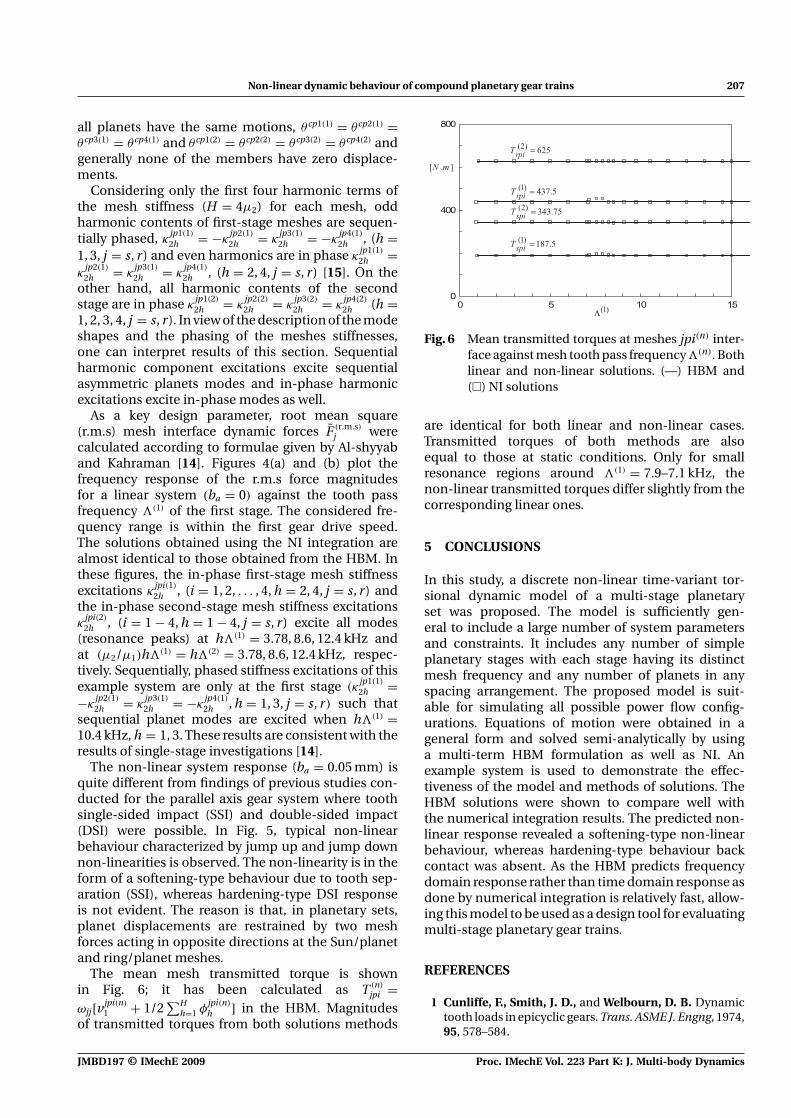
The mean mesh transmitted torque is shownin Fig. 6; it has been calculated as T (n)
jpi =ωjj[vjpi(n)
1 + 1/2∑H
h=1 φjpi(n)
h ] in the HBM. Magnitudesof transmitted torques from both solutions methods
Fig. 6 Mean transmitted torques at meshes jpi(n) inter-face against mesh tooth pass frequency (n). Bothlinear and non-linear solutions. (—) HBM and(�) NI solutions
are identical for both linear and non-linear cases.Transmitted torques of both methods are alsoequal to those at static conditions. Only for smallresonance regions around (1) = 7.9–7.1 kHz, thenon-linear transmitted torques differ slightly from thecorresponding linear ones.
5 CONCLUSIONS
In this study, a discrete non-linear time-variant tor-sional dynamic model of a multi-stage planetaryset was proposed. The model is sufficiently gen-eral to include a large number of system parametersand constraints. It includes any number of simpleplanetary stages with each stage having its distinctmesh frequency and any number of planets in anyspacing arrangement. The proposed model is suit-able for simulating all possible power flow config-urations. Equations of motion were obtained in ageneral form and solved semi-analytically by usinga multi-term HBM formulation as well as NI. Anexample system is used to demonstrate the effec-tiveness of the model and methods of solutions. TheHBM solutions were shown to compare well withthe numerical integration results. The predicted non-linear response revealed a softening-type non-linearbehaviour, whereas hardening-type behaviour backcontact was absent. As the HBM predicts frequencydomain response rather than time domain response asdone by numerical integration is relatively fast, allow-ing this model to be used as a design tool for evaluatingmulti-stage planetary gear trains.
REFERENCES
1 Cunliffe, F., Smith, J. D., and Welbourn, D. B. Dynamictooth loads in epicyclic gears. Trans. ASME J. Engng, 1974,95, 578–584.
JMBD197 © IMechE 2009 Proc. IMechE Vol. 223 Part K: J. Multi-body Dynamics
208 A Al-shyyab, K Alwidyan, A Jawarneh, and H Tlilan
2 Botman, M. Epicyclic gear vibrations. Trans. ASME J.Engng Ind., 1976, 97, 811–815.
3 Antony, G. Gear vibration – investigation of the dynamicbehavior of one stage epicyclic gears. AGMA technicalpaper 88-FTM-12, 1988.
4 Kahraman, A. Free torsional vibration characteristicsof compound planetary gear sets. Mech. Mach. Theory,2001, 36, 953–971.
5 Palmer, W. E. and Fuehler, R. R. Noise control inplanetary transmissions. SAE paper 770561, 1977.
6 Toda, A. and Botman, M. Planet indexing in planetarygears for minimum vibration. ASME paper 79-DET-73,1979.
7 Kahraman, A. Planetary gear train dynamics. Trans.ASME J. Mech. Des., 1994, 116, 713–720.
8 Blankenship, G. W. and Kahraman, A. Steady stateforced response of a mechanical oscillator with com-bined parametric excitation and clearance type non-linearity. J. Sound Vibr., 1995, 185, 743–765.
9 Kahraman, A. and Blankenship, G. W. Interactionsbetween commensurate parametric and forcing excita-tions in a system with clearances. J. Sound Vibr., 1996,194, 317–336.
10 Al-shyyab, A. and Kahraman, A. Non-linear dynamicanalysis of a multi-mesh gear train using multi-termharmonic balance method: sub-harmonic motions. J.Sound. Vibr., 2005, 279, 417–451.
11 Al-shyyab, A. and Kahraman, A. Non-linear dynamicanalysis of a multi-mesh gear train using multi-term har-monic balance method: period-one motions. J. Sound.Vibr., 2005, 284, 151–172.
12 Kahraman, A. Load sharing characteristics of planetarytransmissions. Mech. Mach. Theory, 1994, 29, 1151–1165.
13 Tao, S. and Hai Yan, H. Nonlinear dynamics of a plane-tary gear system with multiple clearances. Mech. Mach.Theory, 2003, 38, 1371–1390.
14 Al-shyyab, A. and Kahraman, A. A non-linear dynamicmodel for planetary gear sets. Proc. IMechE, Part K:J. Multi-body Dynamics, 2007, 221, 567–576. DOI: 10.1243/14644193JMBD92.
15 Yuksel, C. and Kahraman, A. Dynamic tooth loads ofplanetary gear sets having tooth profile wear. Mech.Mach. Theory, 2004, 39, 695–715.
16 Inalpolat, M. and Kahraman, A. Dynamic modeling ofplanetary gears of automatic transmission. Proc. IMechE,Part K: J. Multi-body Dynamics, 2008, 222, 229–242. DOI:10.1243/14644193JMBD138.
APPENDIX 1
Notation
b half of clearance (backlash)c damping coefficientc carrierC contact ratioC sine Fourier coefficientd number of decksD cosine Fourier coefficiente transmission errorE transmission error harmonic component
amplitude
f dimensionless forceF forceg discontinuous displacement functionH number of stiffness harmonic componentsHBM harmonic balance methodI polar mass moment of inertiaJ Jacobian matrixk stiffnessk torsional stiffnessK number of solution harmonic contentsL number of external force harmonic
componentsm massn numberp relative gear mesh displacementp planet gearP relative gear mesh displacement harmonic
componentq discrete time intervalq number of non-linear equationsQ number of discrete pointsr radiusr ring gears sun gearS algebraic equations sett timeT time periodT torqueu displacement harmonic componentv describing functionZ number of gear teeth
� phase angleδ Kronecker deltaζ damping ratioη sub-harmonic indexθ torsional displacementκ dimensionless stiffness tooth mesh frequencyμ integerϕ constant� phase angleψ position angleω frequency angular speed
Sub and superscripts
a characteristic quantityc carriercp planet with respect to carrierj gear indexjpi gear j/planet pi meshp planetr ring gearr.m.s root mean squares sun geart torsional
Proc. IMechE Vol. 223 Part K: J. Multi-body Dynamics JMBD197 © IMechE 2009
Non-linear dynamic behaviour of compound planetary gear trains 209
(n) stage-n(m, n) stage-m couples stage-n(.) differentiation with respect to time(−) dimensional quantity
APPENDIX 2
Definitions of dimensionless quantities ω(n)
ji , ζ(n)
ij , andf (n)
j (t) are
ω(n)
jj =[
bak(n)
jp r (n)
j
ω2aI (n)
j
]1/2
(14a)
ζ(n)
jj = bac(n)
jp r (n)
j
2ω(n)
jj ωaI (n)
j
(14b)
ω(n)
jc =[
bak(n)
jp r (n)
j
ω2aI (n)
ce
]1/2
(14c)
ζ(n)
jc = bac(n)
jp r (n)
j
2ω(n)
jc ωaI (n)ce
(14d)
ω(n)
jp =[
bak(n)
jp r (n)p
ω2aI (n)
p
]1/2
(14e)
ζ(n)
jp = bac(n)
jp r (n)p
2ω(n)
jc ωaI (n)p
(14f)
f (n)
j (t) = T (n)
j (t)
I (n)
j ω2a
(14g)
f (n)c (t) = T (n)
c (t)
I (n)ce ω2
a
(14h)
Similarly ω(n)
j and ω(n,m)
j� are defined as
ω(n,m)
j� =
⎧⎪⎪⎪⎪⎪⎨⎪⎪⎪⎪⎪⎩
[k(n,m)
j�
ω2aI (n)
j
]1/2
, member j of stage-ncouples member �
of stage-m,
0, else
(15a)
ω(n)
j =
⎧⎪⎪⎨⎪⎪⎩
[k(n)
tj
ω2aI (n)
j
]1/2
member j of stage-n is fixed,j ∈ [s, r, c],
≈ 0, free(15b)
The elements of the vector S(n) are given by (n, m ∈[1, 2, . . . , d], j ∈ [s, r], �, k ∈ [1, K ], i ∈ [1, 2, . . . , n(n)
p ])
Sj(n)
1 = [ω(n)
j ]2uj(n)
1 +d∑
m=1m �=n
[ω(n,m)
jk ]2[uj(n)
1 − uk(m)
1 ]
+np∑
i=1
[ω(n)
jp ]2ϕjpi(n)
h − f j(n)
1 (16a)
Sj(n)
2� = −(�)2uj(n)
2�η +np∑
i=1
{2�ζ(n)
jp ω(n)
jp Pjpi(n)
2�η+1
+ [ω(n)
jp ]2C jpi(n)
� } + [ω(n)
j ]2uj(n)
2�η
+d∑
m=1m �=n
[ω(n,m)
jk ]2{uj(n)
2�η − uk(m)
2�η } − f j(n)
2� (16b)
Sj(n)
2�+1 = −(�)2uj(n)
2�η+1 +np∑
i=1
{−2�ζ(n)
jp ω(n)
jp Pjpi(n)
2�η
+ [ω(n)
jp ]2Djpi(n)
� } + [ω(n)
j ]2uj(n)
2�η+1
+d∑
m=1m �=n
[ω(n,m)
jk ]2{uj(n)
2�η+1 − uk(m)
2�η+1} − f j(n)
2�+1 (16c)
Sc(n)
1 = [ω(n)c ]2uc(n)
1 +d∑
m=1m �=n
[ωn(m)
ck ]2{uc(n)
1 − uk(m)
1 }
−np∑
i=1
{[ω(n)sc ]2ϕ
spi(n)
h − [ω(n)rc ]2ϕ
rpi(n)
h } − f c(n)
1
(16d)
Sc(n)
2� = −np∑
i=1
{[ω(n)sc ]2C spi(n)
� + [ω(n)rc ]2C rpi(n)
� }
−np∑
i=1
{2�[ζ (n)sc ω(n)
sc Pspi(n)
2�η+1 + ζ (n)rc ω(n)
rc Prpi(n)
2�η+1]}
− (�)2
[uc(n)
2�η +np∑
i=1
I (n)
pi
I (n)ce
ucpi(n)
2�η
]+ [ω(n)
c ]2uc(n)
2�η
+d∑
m=1m �=n
[ω(n,m)
ck ]2{uc(n)
2�η − uk(m)
2�η } − f c(n)
2� (16e)
Sc(n)
2�+1 =np∑
i=1
{2�[ζ (n)sc ω(n)
sc Pspi(n)
2�η + ζ (n)rc ω(n)
rc Prpi(n)
2�η ]}
−np∑
i=1
{[ω(n)sc ]2Dspi(n)
� + [ω(n)rc ]2Drpi(n)
� }
− (n)2
[uc(n)
2�η+1+np∑
i=1
I (n)
pi
I (n)ce
ucpi(n)
2�η+1
]+[ω(n)
c ]2uc(n)
2�η+1
+d∑
m=1m �=n
[ω(n,m)
ck ]2{uc(n)
2�η+1 − uk(m)
2�η+1} − f c(n)
2�+1 (16f)
Scpi(n)
1 = [ω(n)sc ]2ϕ
spi(n)
h − [ω(n)rc ]2ϕ
rpi(n)
h (16g)
Scpi(n)
2� = −(�)2ucpi(n)
2�η − (�)2uc(n)
2�η + 2ζ (n)sc ω(n)
sc (�)
× Pspi(n)
2�η+1 − 2ζ (n)rc ω(n)
rc (�)Prpi(n)
2�η+1 + [ω(n)sc ]2C spi(n)
�
− [ω(n)rc ]2C rpi(n)
� (16h)
JMBD197 © IMechE 2009 Proc. IMechE Vol. 223 Part K: J. Multi-body Dynamics
210 A Al-shyyab, K Alwidyan, A Jawarneh, and H Tlilan
Scpi(n)
2�+1 = −(�)2ucpi(n)
2�η+1 − (�)2uc(n)
2�η+1 − 2(�)ζ (n)sc ω(n)
sc
× Pspi(n)
2�η + 2ζ (n)rc ω(n)
rc (�)Prpi(n)
2�η + [ω(n)sc ]2Dspi(n)
�
− [ω(n)rc ]2Drpi(n)
� (16i)
where C jpi(n)
k , Djpi(n)
k , and ϕjpi(n) are defined as
C jpi(n)
k = vjpi(n)
2kη+ vjpi(n)
1 κjpi(n)
2k + 12
H∑h=1
κjpi(n)
2h
× [vjpi(n)
2(h−k)η+ vjpi(n)
2(n+k)η+ vjpi(n)
2(k−h)η] + 1
2
H∑h=1
κjpi(n)
2h+1
× [vjpi(n)
2(h−k)η+1 + vjpi(n)
2(k+h)η+1 − vjpi(n)
2(k−h)η+1] (16j)
Djpi(n)
k = vjpi(n)
2kη+1 + vjpi(n)
1 κjpi(n)
2k+1 + 12
H∑h=1
κjpi(n)
2h+1
× [vjpi(n)
2(h−k)η− vjpi(n)
2{k+h)η+ vjpi(n)
2(k−h)η] + 1
2
H∑h=1
κjpi(n)
2h
× [−vjpi(n)
2(h−k)η+1 + vjpi(n)
2(k+h)η+1 + vjpi(n)
2(k−h)η+1](16k)
ϕjpi(n) = vjpi(n)
1 + 12
H∑h=1
[κ jpi(n)
2h vjpi(n)
2hη+ κ
jpi(n)
2h+1 vjpi(n)
2hη+1](16l)
Proc. IMechE Vol. 223 Part K: J. Multi-body Dynamics JMBD197 © IMechE 2009
Related Documents