POUR L'OBTENTION DU GRADE DE DOCTEUR ÈS SCIENCES acceptée sur proposition du jury: Prof. R. Longchamp, président du jury Prof. D. Bonvin, Dr A. Karimi, directeurs de thèse Prof. H. Hjalmarsson, rapporteur Dr L. Miskovic, rapporteur Prof. P. M. J. Van den Hof, rapporteur Non-Iterative Data-Driven Model Reference Control THÈSE N O 4658 (2010) ÉCOLE POLYTECHNIQUE FÉDÉRALE DE LAUSANNE PRÉSENTÉE LE 9 AVRIL 2010 À LA FACULTÉ SCIENCES ET TECHNIQUES DE L'INGÉNIEUR LABORATOIRE D'AUTOMATIQUE PROGRAMME DOCTORAL EN INFORMATIQUE, COMMUNICATIONS ET INFORMATION Suisse 2010 PAR Klaske VAN HEUSDEN

Welcome message from author
This document is posted to help you gain knowledge. Please leave a comment to let me know what you think about it! Share it to your friends and learn new things together.
Transcript

POUR L'OBTENTION DU GRADE DE DOCTEUR ÈS SCIENCES
acceptée sur proposition du jury:
Prof. R. Longchamp, président du juryProf. D. Bonvin, Dr A. Karimi, directeurs de thèse
Prof. H. Hjalmarsson, rapporteur Dr L. Miskovic, rapporteur
Prof. P. M. J. Van den Hof, rapporteur
Non-Iterative Data-Driven Model Reference Control
THÈSE NO 4658 (2010)
ÉCOLE POLYTECHNIQUE FÉDÉRALE DE LAUSANNE
PRÉSENTÉE LE 9 AVRIL 2010
À LA FACULTÉ SCIENCES ET TECHNIQUES DE L'INGÉNIEUR
LABORATOIRE D'AUTOMATIQUE
PROGRAMME DOCTORAL EN INFORMATIQUE, COMMUNICATIONS ET INFORMATION
Suisse2010
PAR
Klaske VAN HEUSDEN


Acknowledgements
First of all I would like to thank Dr. Alireza Karimi. This thesis isthe result of many of our short, long and even longer discussions.Thank you for always being available to answer my questions, foryour calmness and for your capability of putting things in perspec-tive. Thanks also to professor Dominique Bonvin for the valuablefeedback and support.
Several other people have contributed to this thesis, either di-rectly or indirectly. Many thanks to professor Torsten Söderström,professor Maarten Steinbuch and Arjen den Hamer for their collab-oration. Thanks to professor Robert Bitmead, who’s remarks indi-rectly led to some of the results in this thesis. I would also like tothank the members of my thesis committee for their thorough read-ing of this thesis.
Thanks to professor Roland Longchamp, professor DominiqueBonvin and Dr. Denis Gillet for having accepted me as a PhD studentin the Automatic Control laboratory. Thanks to my colleagues at theLA for contributing to the enjoyable atmosphere in the lab. Thanksto the LA secretaries and technical staff, for facilitating life in manyways. A special thanks goes to my office mates Yvan, Damien andBasile. Sorry I had to cut down on the breaks lately.
The years spent in Lausanne working on this thesis were veryenjoyable, for which many of the people I got to know here are re-sponsible. Thanks to Karin, for everything (but obviously mainlythe cooking), Chloe (for the ironing), Antoine (the perfect flatmate),

ii
Nino (no it really wasn’t him), Annabelle (for the funny stories atsat), Seb, Davor, Jo, Andrea and all the others that I do not mentionhere for some unexplainable reason. Thanks to my friends at the skischool for the entertainment in winter and to my friends of the KayakClub Lausanne for the distraction in summer. Thanks also to Mikeand Fleur for taking the brilliant decision of moving to Geneva andto Maaike, Marije, Sarah, Imme and Maja, cause some things willnever change. Last but not least, I cannot think of a better way todescribe my appreciation of the support of my parents than to say:’t kon minder.

Abstract
In model reference control, the objective is to design a controllersuch that the closed-loop system resembles a reference model. In thestandard model-based solution, a plant model replaces the unknownplant in the design phase. The norm of the error between the con-trolled plant model and the reference model is minimized. The orderof the resulting controller depends on the order of the plant model.Furthermore, since the plant model is not exact, the achieved closed-loop performance is limited by the quality of the model.
In recent years, several data-driven techniques have been pro-posed as an alternative to this model-based approach. In these ap-proaches, the order of the controller can be fixed. Since no modelis used, the problem of undermodeling is avoided. However, closed-loop stability cannot, in general, be guaranteed. Furthermore, thesetechniques are sensitive to measurement noise.
This thesis treats non-iterative data-driven controller tuning.This controller tuning approach leads to an identification problemwhere the input is affected by noise, and not the output as in stan-dard identification problems. A straightforward data-driven tuningscheme is proposed, and the correlation approach is used to deal withmeasurement noise. For linearly parameterized controllers, this leadsto a convex optimization problem. The accuracy of the correlationapproach is compared to that of several solutions proposed in the lit-erature. It is shown that, if the order of the controller is fixed, both

iv
the correlation approach and a specific errors-in-variables approachcan be used.
The model reference controller-tuning problem is extended witha constraint that ensures closed-loop stability. This constraint is de-rived from stability conditions based on the small-gain theorem. Forlinearly parameterized controllers, the resulting optimization prob-lem is convex. The proposed constraint for stability is conservative.As an alternative, a non-conservative a posteriori stability test isdeveloped based on similar stability conditions.
The proposed methods are applied to several numerical and ex-perimental examples.
Keywords: Data-driven controller tuning, convex optimization,closed-loop stability, bias error, variance error

Résumé
L’objectif de la commande par modèle de référence est de di-mensionner un régulateur afin que le système en boucle fermée secomporte comme le modèle de référence (ou modèle de poursuite).La solution classique utilise un modèle du système pour minimiser lanorme de l’erreur entre ce modèle du système en boucle fermée et lemodèle de poursuite. L’ordre du régulateur dépend ainsi de l’ordredu modèle. La performance en boucle fermée est limitée par la qualitédu modèle.
Plusieurs techniques pour la synthèse d’un régulateur à partirde données expérimentales ont été proposées récemment. Ces tech-niques offrent une alternative aux techniques basées sur un modèle.L’ordre du régulateur peut être fixé à l’avance. Puisque aucun mo-dèle du système n’est utilisé, le problème de sous-modélisation estévité. Pourtant, la stabilité du système en boucle fermée ne peut gé-néralement pas être garantie. De plus, ces techniques sont sensiblesau bruit de mesure.
Dans cette thèse on étudie la synthèse non-itérative d’un ré-gulateur basée sur les données. Cette approche directe mène à unproblème d’identification, où contrairement aux problèmes d’iden-tification standards, l’entrée, et non pas la sortie, est affectée parle bruit de mesure. Un schéma simple est proposé pour la synthèsedes régulateurs et l’approche de corrélation est utilisés pour éliminerl’effet du bruit de mesure. Le problème d’optimisation résultant estconvexe si la paramétrisation du régulateur est linéaire. La précision

vi
de l’approche de corrélation est comparée à la précision d’autres so-lutions proposées dans la littérature. Si l’ordre du régulateur est fixe,l’approche de corrélation ainsi qu’une approche spécifique pour desproblèmes EIV (errors-in-variables) peuvent être utilisés.
Afin de garantir la stabilité du système en boucle fermée, unecontrainte est ajoutée au problème de la commande par modèle deréférence. Le problème d’optimisation sous contrainte est convexe sila paramétrisation du régulateur est linéaire. La contrainte de stabi-lité est basée sur le théorème des petits gains et est par conséquentconservatrice. Une alternative consiste à vérifier la stabilité a poste-riori. Un test de stabilité non-conservatrice est développé basée surles mêmes conditions.
Les méthodes proposées sont appliquées à plusieurs exemples nu-mériques et expérimentaux.
Mots-clés : Synthèse d’un régulateur à partir de données expéri-mentales, optimisation convexe, stabilité en boucle fermée, erreur debiais, erreur de variance

Contents
1 Introduction . . . . . . . . . . . . . . . . . . . . . . . . . . . . . . . . . . . . . . . 11.1 Motivation . . . . . . . . . . . . . . . . . . . . . . . . . . . . . . . . . . . . . 11.2 State of the art . . . . . . . . . . . . . . . . . . . . . . . . . . . . . . . . . 3
1.2.1 Data-driven controller tuning . . . . . . . . . . . . . . . 51.2.2 Model-based fixed-order controller design . . . . . 121.2.3 Ensuring closed-loop stability . . . . . . . . . . . . . . . 14
1.3 Contributions . . . . . . . . . . . . . . . . . . . . . . . . . . . . . . . . . . . 151.4 Outline . . . . . . . . . . . . . . . . . . . . . . . . . . . . . . . . . . . . . . . . 17
2 Non-iterative data-driven controller tuning: anidentification problem . . . . . . . . . . . . . . . . . . . . . . . . . . . . . 192.1 An approximate model reference criterion . . . . . . . . . . 192.2 Non-iterative data-driven controller tuning schemes . . 22
2.2.1 Tuning scheme for stable plants . . . . . . . . . . . . . 222.2.2 Tuning scheme for unstable plants . . . . . . . . . . . 232.2.3 Definitions and assumptions . . . . . . . . . . . . . . . . 24
2.3 Analysis of the controller identification problem . . . . . 262.3.1 Controller identification in the prediction
error framework . . . . . . . . . . . . . . . . . . . . . . . . . . . 262.3.2 Full-order controllers: no undermodeling . . . . . 282.3.3 Fixed-order controllers: undermodeling of
the controller . . . . . . . . . . . . . . . . . . . . . . . . . . . . . 302.4 Application of the correlation approach . . . . . . . . . . . . 31
2.4.1 Use of open-loop experiments . . . . . . . . . . . . . . . 32

viii Contents
2.4.2 Use of closed-loop experiments . . . . . . . . . . . . . . 342.4.3 Use of a finite number of data . . . . . . . . . . . . . . . 362.4.4 Use of periodic data . . . . . . . . . . . . . . . . . . . . . . . 38
2.5 Application to a double SCARA robot . . . . . . . . . . . . . 392.6 Conclusions . . . . . . . . . . . . . . . . . . . . . . . . . . . . . . . . . . . . . 50
3 Data-driven controller tuning with guaranteedstability . . . . . . . . . . . . . . . . . . . . . . . . . . . . . . . . . . . . . . . . . . . 533.1 Model reference control with guaranteed stability . . . . 543.2 Data-driven approach for stable minimum-phase
systems . . . . . . . . . . . . . . . . . . . . . . . . . . . . . . . . . . . . . . . . 563.3 Data-driven approach for nonminimum-phase or
unstable systems . . . . . . . . . . . . . . . . . . . . . . . . . . . . . . . . 623.4 Alternative implementation using Toeplitz matrices . . 643.5 Guaranteeing stability for a finite number of data . . . . 663.6 Illustrative examples . . . . . . . . . . . . . . . . . . . . . . . . . . . . . 70
3.6.1 Numerical example: delay system . . . . . . . . . . . 703.6.2 Numerical example: flexible transmission
system . . . . . . . . . . . . . . . . . . . . . . . . . . . . . . . . . . . 713.6.3 Experimental torsional setup . . . . . . . . . . . . . . . . 74
3.7 Conclusions . . . . . . . . . . . . . . . . . . . . . . . . . . . . . . . . . . . . . 77
4 Data-driven stability test . . . . . . . . . . . . . . . . . . . . . . . . . . 794.1 Conditions for closed-loop stability . . . . . . . . . . . . . . . . 804.2 Generating the error signal . . . . . . . . . . . . . . . . . . . . . . . 844.3 Controller validation . . . . . . . . . . . . . . . . . . . . . . . . . . . . . 874.4 Combining information from different closed-loop
experiments . . . . . . . . . . . . . . . . . . . . . . . . . . . . . . . . . . . . 884.5 Numerical example . . . . . . . . . . . . . . . . . . . . . . . . . . . . . . 924.6 Conclusions . . . . . . . . . . . . . . . . . . . . . . . . . . . . . . . . . . . . . 93
5 Accuracy of non-iterative model reference control . 955.1 Accuracy of data-driven approaches . . . . . . . . . . . . . . . . 97
5.1.1 Prediction error methods . . . . . . . . . . . . . . . . . . . 975.1.2 Instrumental variables . . . . . . . . . . . . . . . . . . . . . 985.1.3 Identifying the inverse of the controller using
PEM . . . . . . . . . . . . . . . . . . . . . . . . . . . . . . . . . . . . 1005.1.4 Correlation approach . . . . . . . . . . . . . . . . . . . . . . 103

Contents ix
5.1.5 Periodic errors-in-variables approach . . . . . . . . . 1045.2 Comparison of data-driven approaches . . . . . . . . . . . . . 107
5.2.1 Asymptotic accuracy . . . . . . . . . . . . . . . . . . . . . . 1075.2.2 Numerical example . . . . . . . . . . . . . . . . . . . . . . . . 109
5.3 Model-based versus data-driven model referencecontrol . . . . . . . . . . . . . . . . . . . . . . . . . . . . . . . . . . . . . . . . . 1115.3.1 Model-based model reference control . . . . . . . . . 1135.3.2 Controller tuning using a full-order FIR model 1145.3.3 Asymptotic accuracy . . . . . . . . . . . . . . . . . . . . . . 1185.3.4 Numerical example . . . . . . . . . . . . . . . . . . . . . . . . 119
5.4 Conclusions . . . . . . . . . . . . . . . . . . . . . . . . . . . . . . . . . . . . . 120
6 Conclusions . . . . . . . . . . . . . . . . . . . . . . . . . . . . . . . . . . . . . . . . 123
A Appendix . . . . . . . . . . . . . . . . . . . . . . . . . . . . . . . . . . . . . . . . . . 127A.1 Bias in correlation approach for finite data length . . . 127A.2 Proof of Theorem 3.6 . . . . . . . . . . . . . . . . . . . . . . . . . . . . 128A.3 Proof of Theorem 3.7 . . . . . . . . . . . . . . . . . . . . . . . . . . . . 131A.4 Proof of Theorem 4.3 . . . . . . . . . . . . . . . . . . . . . . . . . . . . 135A.5 Proof of Theorem 5.1 . . . . . . . . . . . . . . . . . . . . . . . . . . . . 137A.6 Proof of Proposition 5.1 . . . . . . . . . . . . . . . . . . . . . . . . . . 138
References . . . . . . . . . . . . . . . . . . . . . . . . . . . . . . . . . . . . . . . . . . . . . 143
Curriculum Vitae . . . . . . . . . . . . . . . . . . . . . . . . . . . . . . . . . . . . . . 151


Notation
Abbreviations and acronyms
DFT Discrete Fourier transformETFE Empirical transfer function estimateEIV Errors-in-variablesFIR Finite impulse responseFRF Frequency response functionICbT Iterative Correlation-based TuningIFT Iterative Feedback TuningIV Instrumental variableLMI Linear matrix inequalityLTI Linear time invariantMIMO Multi-input multi-outputML Maximum likelihoodMRAC Model Reference Adaptive ControlPEM Prediction error methodPRBS Pseudo random binary sequenceSISO Single-input single-outputSNR Signal-to-noise ratioSTR Self-Tuning RegulationVRFT Virtual Reference Feedback Tuning


1
Introduction
1.1 Motivation
The robot shown in Figure 1.1 is designed to perform pick-and-placetasks with high accuracy. The structure is designed such that thesetasks can be performed with high velocity. This hardware is the nec-essary basis to achieve the performance required in modern robotics.To actually achieve the required performance, a feedback controllerneeds to be designed that ensures both safe operation and precisionof movements with high velocity.
The control engineer has a large choice of possible control strate-gies to achieve the required task. He or she can decide to develop amodel of the system based on the geometry of the robot and physi-cal laws (known as first-principle modeling). This model can then beused to design a controller and to evaluate the performance specifi-cations for the feedback loop of the controller and the model. If thisdesign is performed carefully, the controller achieves the requiredperformance when applied to the model. However, this does notguarantee that the controller achieves the required performance whenapplied to the robot. The model is necessarily a simplification of thereal plant. Furthermore, variables such as the inertia of the robotarm are not known exactly. The achieved performance depends onthe mismatch between the plant and the model. Besides limited per-formance due to limited model accuracy, first-principle modeling isin general time-consuming and therefore expensive.

2 1 Introduction
Fig. 1.1. Pick-and-place robot.
The control engineer can also decide to use system identificationtechniques, where a mathematical model is derived from observeddata from the plant. In this case, identification experiments needto be designed and performed and an appropriate model structureneeds to be chosen. The collected set of data is then used to identifythe parameters of this model structure and the identified model canbe used to design a controller. This approach thus uses two optimiza-tions, one in the identification step and a second one in the controllerdesign. As for first-principle modeling, the identification step intro-duces in general a mismatch between the model and the plant, andthe performance of the controller is limited by this mismatch.
An additional difficulty of model-based approaches is that thecomplexity of the resulting controller depends, in general, on thecomplexity of the model. The order of the controller might actuallybe too high to be implemented, and a controller-order reduction stepmight be needed before implementation.
In recent years, several data-driven techniques have been pro-posed as an alternative to the model-based approaches describedabove. In a data-driven approach, the data are used directly tominimize a control criterion. The identification and controller de-sign steps are thus lumped together, resulting in a direct “data-to-

1.2 State of the art 3
controller” algorithm. Compared to a model-based approach, themodeling step is omitted and the problem of undermodeling of theplant is avoided. Furthermore, since there is no intermediate model,the structure of the designed controller does not depend on the struc-ture of this model, and the order and structure of the controller canbe fixed.
Even though these data-driven techniques have been shown ef-fective on various application examples, the control engineer is notlikely to choose such a method, mainly because it cannot ensure safeoperation of the robot. Since measured data are used directly tocompute the controller that minimizes a control objective, no modelof the plant is needed for controller design. Consequently, no model isavailable to verify the robustness margins either, and stability cannotbe guaranteed before actual controller implementation. Another dif-ficulty, related to the stability problem, is that without a model it isdifficult to verify whether the defined control objectives are actuallyachievable. Furthermore, the effectiveness of data-driven approachesis strongly affected by measurement noise.
Development of a method that guarantees closed-loop stabilityfor data-driven controller tuning is a necessary step towards a seri-ous alternative to model-based approaches. Furthermore, solutionsare needed that deal with the effect of noise. Ideally, a data-drivenapproach comprises a complete controller design recipe that includesexperiment design and an approach to define adequate control ob-jectives.
1.2 State of the art
This thesis studies data-driven controller tuning. Such techniquesare often compared to or even opposed to model-based techniques.However, both terms are ambiguous. Many techniques can be re-ferred to as model-based, and their characteristics differ considerably.Methods that use identification techniques to estimate a model fromdata, and then use this model to calculate a controller are sometimesreferred to as model-based, but have also been named data-driven.The following definition clarifies which techniques are referred to bythe term model-based approach in this thesis.

4 1 Introduction
Definition 1.1 (Model-based approach) Two distinct steps areused to calculate the controller. In a first step a model of the plant isdefined. In a second step the controller is calculated using the model,algebraically or by optimization.
Methods that use first-principle modeling to define a plant model,and then use this model to calculate a controller are an example ofsuch model-based techniques. Methods that use identification tech-niques (an optimization) to define a model of the plant, and then usethe model parameters in a second optimization for controller designare another example.
In contrast to these model-based approaches, the term data-driven approach refers to techniques with the following property.
Definition 1.2 (Data-driven approach) Measured data are useddirectly to minimize a control criterion. Only one optimization inwhich the controller parameters are the optimization variables is usedto calculate the controller.
In these definitions model-based approaches can be regarded as indi-rect, whereas data-driven approaches are direct. Note that a methodthat identifies a plant model parameterized directly in terms of thecontroller parameters is also an example of a direct approach. Inthis case no intermediate model parameters are involved and thecontroller parameters are estimated directly from the data.
Various data-driven controller tuning methods have been pro-posed in the literature. A non-exhaustive overview is given in Sec-tion 1.2.1. Two adaptive control schemes are treated, but the mainfocus is on more recent approaches, like Iterative Feedback Tuning(IFT), Iterative Correlation-based Tuning (ICbT), unfalsified con-trol, and Virtual Reference Feedback Tuning (VRFT). Controllertuning methods that use non-parametric frequency domain modelsare also discussed.
In non-iterative data-driven controller tuning, a set of measureddata from one single experiment is used to calculate a fixed-ordercontroller. The exact same data set could be used to identify amodel of the plant, which can then be used to calculate a controller.In model-based techniques, the order of the resulting controller is ingeneral related to the order of the model. Identification of models

1.2 State of the art 5
that can be used for fixed- or low-order controller design is treatedin Section 1.2.2.
One of the main challenges in data-driven controller tuning isclosed-loop stability. In Section 1.2.3, ideas to incorporate conditionsfor closed-loop stability in the controller design are discussed, as wellas a posteriori stability tests.
1.2.1 Data-driven controller tuning
Adaptive control
In the 1950’s, extensive research on adaptive control was triggeredby the development of autopilots for aircrafts [6]. These systemsfunction over a wide range of operating conditions, related to thespeed and altitude of the aircraft. Adaptive schemes were developedto deal with changing conditions. Measured data are used in feedbackto adapt the controller continuously.
The literature on adaptive control is extensive, see for example [6]and [48]. In the following, two specific schemes are summarized,Model Reference Adaptive Control (MRAC) and Self-Tuning Regu-lation (STR).
In MRAC, the control objective is given as a reference model,which generates an ideal plant output for the applied reference sig-nal. The parameters of the controller are then adjusted such thatthe error between this ideal output and the measured output of theplant is minimized. This approach is direct, since the parametersof the controller are adjusted without the use of an intermediatemodel. In the original MRAC, the MIT rule was used to updatethe controller parameters [60]. The parameter update is based on asteepest descend approach, where the update is proportional to thederivative of the objective function with respect to the parameters.The gradient can, for example, be estimated using a model of theplant. Other update rules have been proposed, for example based onstability theory [6].
STR is an indirect adaptive approach. The measured data areused to identify a plant model. The controller is then calculated on-line, using this updated plant model. This scheme is very flexibleas different identification approaches and different controller design

6 1 Introduction
methods can be combined. Because the design calculations can betime consuming, the model can be reparameterized to simplify thedesign step. A model that is parameterized using the controller pa-rameters is called a direct parameterization. It can be shown that,in some specific cases, an MRAC approach is equivalent to an STRapproach that uses a direct parameterization ( [6], p. 182).
Stability of adaptive control methods cannot be guaranteed ingeneral [4]. One of the problems due to the continuous controllerupdates is related to persistence of excitation. If the controlled plantfunctions at steady state, the ideal controller achieves a constanterror. Consequently, the measured signals are not rich enough toidentify a correct model, resulting in a parameter update that drivesthe controller away from the ideal controller. As a result, the er-ror increases and a correct model can, again, be identified. Thisphenomenon is called bursting [2].
In the adaptive control approaches described above, the controlleror model parameters are estimated. These estimates are then usedas if they represent the true system. This is called the “certaintyequivalence principle” [6]. Unmodeled dynamics and estimation un-certainties are not taken into account.
Iterative Feedback Tuning
In practice, the “certainty equivalence principle” is not realistic. Sincethe order of the controller is limited and modeling errors cannot beavoided, the controller performance is limited by the quality of themodel. Iterative Feedback Tuning (IFT) can be used to overcomethese problems. IFT was initially not intended to deal with time-varying systems. It is a fine tuning approach that optimizes an initialfixed-order controller that does not meet the performance specifica-tions. Experiments are performed with one fixed controller. A newcontroller is then calculated off-line.
The approach was first proposed in [30]. The control objectiveis formulated as a desired trajectory for the given reference signal,which can for example be generated using a reference model. Thecontrol objective is then minimized using a gradient approach to finda (local) optimum, with the initial controller as a starting point. Ateach iteration, closed-loop experiments are performed and the re-

1.2 State of the art 7
sponse of the plant is used directly to estimate the gradient. Noplant model is needed and the estimate of the gradient is unbiased.The controller parameters are updated using a stochastic approxi-mation procedure. Convergence of the method to a local optimum isshown in [30], provided the measured signals remain bounded. Theoptimization thus converges, if the successive controllers are all sta-bilizing.
IFT was initially developed for LTI SISO systems. The methodwas then extended to LTI MIMO systems [27]. Analysis of themethod for nonlinear systems is provided in [26]. Performance ofthe method has been shown in several application examples, see [28]for an overview. A gradient approach that is similar to IFT is pro-posed in [37]. In this method, the gradients are calculated usingnon-parametric frequency domain descriptions of the current closed-loop system.
The controller parameters converge to a local minimum, providedthe successive controllers all stabilize the system. Unfortunately,guaranteeing stability is not straightforward and it is in general notknown whether this condition is satisfied. In [33], it is proposed tominimize an H∞ criterion that ensures robust stability. A robustH2 criterion is also proposed. In [66], a robust criterion is proposed,where a second term that represents robustness is added to the orig-inal performance criterion. The optimal controller that minimizesthese criteria is robust, but stability cannot be guaranteed through-out the iterations. The choice of an adequate control criterion fornonminimum-phase plants is discussed in [52], where a degree of free-dom in the reference model is introduced to avoid cancelation of theunstable zero.
IFT can also be used for disturbance rejection, where the normof the system output due to noise is minimized. For each iteration,one experiment is performed in the standard operating conditions,without excitation of the reference signal. A second experiment isperformed to estimate the gradient, with excitation of the reference.The convergence rate of the algorithm depends on the quality of thegradient estimate, which is analyzed in [25]. The excitation in thefirst experiment is the noise, which cannot be adjusted to improve theaccuracy. In [24], the reference signal used in the second experiment

8 1 Introduction
is shaped using a prefilter to improve the convergence rate. In [35],addition of external excitation is proposed to improve convergence.
Iterative Correlation-based Tuning
In Iterative Correlation-based Tuning (ICbT), the control criterionis defined as a reference model. Instead of minimizing the norm of anerror signal related to the model reference criterion, the correlationbetween the known reference signal and the error signal is minimized.The resulting controller is asymptotically insensitive to noise [57].
A correlation function is defined as the mathematical expecta-tion of the multiplication of an instrumental variable and the modelreference error. If the complexity of the controller is sufficient toachieve the model-reference objective, decorrelation of the instru-mental variables and the error signal can be achieved using the iter-ative Robbins-Monro stochastic approximation algorithm [43]. If alarge number of data is available, the Newton-Raphson algorithm fordeterministic optimization can be used to improve the convergencespeed [42]. The accuracy of the controller parameters is analyzedin [43], where conditions for convergence are also given. Comparedto IFT, fewer experiments are needed per iteration, but a model isused to calculate the gradient. The effect of undermodeling on theconvergence is studied.
If the complexity of the controller is not sufficient to match themodel-reference criterion, complete decorrelation cannot be achieved.In this case, a norm of the correlation can be minimized. For a spe-cific choice of extended instrumental variables, the optimal controllerminimizes the model reference criterion weighted by the square ofthe power spectrum of the reference signal [41]. Specifications onthe input sensitivity can be added to the approach [58]. In [57], theapproach is adapted for disturbance rejection.
The method has been extended to MIMO controllers [59]. Theprocedure decouples the system by decorrelating the reference fromthe non-corresponding outputs. A single experiment is sufficient periteration, in contrast to other data-driven methods, where the num-ber of experiments increases with the number of inputs and outputs.The variance of the controller parameters is analyzed for simulta-neous excitation of the different reference signals and for separated

1.2 State of the art 9
excitation. It is shown that the variance is smaller is the referencesignals are excited separately.
The correlation approach has also been applied to precompen-sator tuning [38].
Unfalsified control
Unfalsified control, introduced in [70], uses the philosophical princi-ple that a scientific theory cannot be proven to be true, but that thebest one can do is to show that a hypothesis is wrong, i.e. a falsehypothesis can be falsified by observations. In unfalsified control,a set of controllers is considered and the control specifications aredefined as a function of a time-domain reference signal, input to theplant and output of the system controlled by each controller in theset. These signals can be computed ‘virtually’, for each controller inthe set, using only one set of measured data. If the virtual signalsdo not satisfy the control specifications, the controller is falsified anddiscarded. The algorithm can be implemented recursively or in batchadaptation.
The control specifications need to be verified for each controllerin the set. In the early publications on unfalsified control, the con-troller set was therefore discrete, and for fixed-order controllers theparameter spaces were gridded. In ellipsoidal unfalsified control [81],the parameter space is continuous and the parameters can be up-dated analytically, which reduces the computational load consider-ably. Several application examples have been reported and a con-siderable effort has been made towards stability and convergence ofthe method, see [81] and [4] and the references therein. It is shownin [15] that, even though under certain hypotheses convergence toa stabilizing controller can be guaranteed, this does not prevent thesystem response to become arbitrarily large before convergence, andunfalsified control can therefore not be applied safely.
An H∞ approach named iterative controller unfalsification is pro-posed in [47]. The approach uses time-domain data to evaluate anH∞-norm control criterion. The approach converges as the length ofan experiment tends to infinity, but neither convergence nor stabilitycan be shown for the proposed iterative approach. Furthermore, theapproach is sensitive to measurement noise [31].

10 1 Introduction
Virtual Reference Feedback Tuning
The concept of virtual reference controller design was first intro-duced in [23]. By using a specific filtering scheme, an error signalcorresponding to an approximate model reference error can be evalu-ated for each controller using only one experiment and no iterationsare needed to minimize an approximate model reference criterion.
Several papers have treated this approach since, e.g. [9, 71]. Anextension to the original method with appropriate weighting forfixed-order controllers is presented as Virtual Reference FeedbackTuning (VRFT) in [9]. If the controller is parameterized linearly,the optimization problem becomes convex and, in contrast to IFTand ICbT, convergence to the global optimum can be shown. Themethod is developed for noise-free measurements. For noisy mea-surements, the use of instrumental variables is proposed. In [71],several remarks and extensions to [9] are proposed. The use of aprediction error method (PEM) for the identification of the inversecontroller is suggested to deal with measurement noise.
In [31], the use of cross-correlations is suggested for identifica-tion for control and it is shown how VRFT fits into the proposedframework. The paper discussed asymptotic properties. Many ex-tended instrumental variable techniques as well as some frequencydomain approaches fit into the proposed framework, but no detailedidentification algorithm is presented.
Several examples of application of VRFT have been reported,e.g. [10, 65]. The method has been extended to 2 degree-of-freedomcontrollers [51] and to nonlinear plants [11]. In [46], a technique de-rived from VRFT is proposed, which intends to shape both the sensi-tivity and complementary sensitivity functions. The main differencewith VRFT is that the sensitivity and complementary sensitivity donot necessarily match those of one and the same reference model.The resulting controller does not minimize an (approximate) modelreference criterion, but provides a trade-off between a match of thesensitivity and a match of the complementary sensitivity function.The resulting tuning scheme is very simple.

1.2 State of the art 11
The techniques mentioned above summarize the main results in data-driven controller tuning. Other ideas have been reported, for examplethe use of the behavioural approach in [56], where the measurementsare assumed to be noise-free. Most of the methods discussed aboveuse time-domain data. Approaches using frequency-domain data canalso be found under the name “direct” or “data-driven”. Some recentfrequency-domain results are discussed next.
Frequency-domain methods
In [34], it is proposed to use frequency response function (FRF) datafrom a system to directly identify a controller. It is argued that,since no intermediate optimization step is used for the identificationof this FRF, the problem of undermodeling of the plant is avoided andconsequently the resulting performance limitation due to the plant-model mismatch is also avoided. One can argue whether such anapproach is truly data-driven, since an explicit representation of theplant is used. However, this non-parametric model can be measureddirectly, or computed from time-domain data without any optimiza-tion step, in which case it can be seen as a representation of themeasured data in the frequency domain. Furthermore, the claimedadvantage that undermodeling of the plant is avoided corresponds tothe main motivation for data-driven techniques.
An H2 and an LQG scheme are proposed in [34]. The robustnessissue is taken into account by adding a stability term to the costfunction, which penalizes solutions that approach the critical pointin the Nyquist curve. In [18], a direct approach for H∞ controllerdesign is proposed using FRF data.
In [40] and [39], non-parametric frequency-domain models areused to design fixed-order controllers. In [40], the open-loop transferfunction is shaped using linear programming. Robustness marginsare imposed as bounds in the Nyquist diagram. In [39], it is shownhow the H∞ robust performance condition can be approximated inthe Nyquist diagram. For linearly parameterized controllers, the re-sulting constraints are convex. The approach can handle frequency-domain uncertainty as well as multimodel uncertainty.

12 1 Introduction
Challenges of direct data-driven control
In a recent review of challenges encountered in adaptive control [4],model-free approaches as well as iterative identification and controlare considered. It is shown that the problems encountered in thesemethods are similar to some of the known problems of adaptive con-trol. A major theoretical problem is closed-loop stability. A secondproblem, which is closely connected to the stability problem, is thechoice of the control objective. In data-driven and iterative iden-tification and control techniques, a full description of the plant islacking. It is therefore impossible to decide beforehand whether thedefined control objective can be achieved. If the control objectiveis inadequate, at least, the desired performance will not be achievedand, at worst, the closed-loop might be unstable. In [31], a sim-ple analytical example shows an unachievable control objective thatleads to destabilizing optimal controllers in model-free approaches.
1.2.2 Model-based fixed-order controller design
In a model-based approach, the order of the controller typically de-pends on the order of the plant. In order to limit the order of thecontroller, it is therefore desirable to limit the order of the model.An overview of identification of restricted-complexity models can befound in [29]. In the following, identification of low-order modelsfor controller design is discussed and some results on the accuracyof model reduction and direct identification of low-order models aregiven.
Identifying low-order models for controller design
If the order of the model is limited, a bias error exists between themodel and the plant due to undermodeling. It has been shown thatbias shaping, i.e. imposing a frequency dependent weighting on thiserror due to undermodeling, is essential for meeting the control per-formance [20]. The main idea is that the modeling error can be largein frequency zones that are not important for the resulting closed-loop performance, but the error must be limited in other frequencyzones, typically around the bandwidth of the closed-loop system.

1.2 State of the art 13
The identification criterion used to identify the plant must thus beconnected to the control objective.
In [67], this idea is used for model reduction. An optimal low-order model for controller design is calculated by minimizing a cri-terion that reflects the control objective. The optimal weighting foridentification of the plant model actually depends on the controllerthat is to be designed. This observation is the basis of iterative iden-tification and control techniques, see [1] for an overview. The idea isthat a first model is identified in closed-loop operation. This modelis then used to calculate a new controller, which is implemented.A new model is identified with this new controller, thus resultingin an iterative approach. The quality of consecutive models shouldimprove, because the frequency weighting approaches the optimalweighting as the controller approaches the ideal controller. However,convergence of such methods cannot be shown.
If an approximation of the ideal filter is used, bias shaping canbe done by prefiltering of the data, where the approximate filter isapplied to the data before identification of the plant. This approachis non-iterative. According to [29], VRFT can be seen as such aprefiltering approach, where the low-order plant is parameterizedthrough the parameterization of the controller. This parameteriza-tion is known in adaptive control as the direct parameterization.
A statistical view on identification of low-order models
Low-order models can either be identified directly from data, or becalculated in a model-reduction step, after having identified a high-order model. An obvious question is then, which of these methodsshould be preferred? Should one first identify a full-order model andthen use this model for further calculations or is it better to identifya reduced-order model directly? This question is treated in [29].
The discussion in [29] is based on the so-called separation princi-ple, which uses the invariance principle of maximum-likelihood (ML)estimation (Theorem 5.1.1 [84]). Let g : Θ → Ω be a function map-ping θ ∈ Θ ∈ Rn to an interval Ω ∈ Rm, with m 6 n. The theoremstates that, if θ is a maximum-likelihood estimator of θ, then g(θ) isa maximum-likelihood estimator of g(θ).

14 1 Introduction
According to [29], “it follows under very general conditions on
g that, if θ is asymptotically efficient, i.e. it is consistent and itsasymptotic covariance matrix reaches the Cramér-Rao lower limit,then g(θ) is also asymptotically efficient.” The results of [80] onmodel reduction confirm this idea.
According to this separation principle, a full-order model can beidentified and then used in further calculations without jeopardiz-ing the asymptotic efficiency. However, the properties for a finitenumber of data of such an asymptotically efficient estimator are notnecessarily optimal.
1.2.3 Ensuring closed-loop stability
Ideally, a control-design method should guarantee closed-loop sta-bility. Attempts to incorporate a stability condition at the designstage can be found for iterative identification and control [53]. Themain idea is that, if the controller change is small enough, insta-bility cannot occur. This idea of cautious controller updates andgradual performance increase is widely accepted in iterative identi-fication and control [3, 7]. If the design method does not include astability guarantee, the controller can be tested before actual imple-mentation. Several tests have been developed to verify closed-loopstability before implementation of the controller.
In [37], it is suggested to include an a posteriori stability testin an iterative controller-tuning scheme. The stability condition isbased on ν-gap metrics and can be verified using spectral estimatesof the current closed-loop system, which are also used in the iterativescheme. Extensions to the approach are given in [36]. In [62], theν-gap metric is used not only to ensure stability conditions but alsoto ensure a certain closed-loop performance. For validation of theconditions, the H∞-norm of a matrix of loop-transfer functions withthe current controller in the loop needs to be identified.
In [83], it is shown that it is impossible to ensure stability in it-erative unfalsification and control schemes, based on a finite numberof data and without additional information on the plant. A prioriassumptions are necessary in order to guarantee stability. An algo-rithm that uses an a priori assumption on the maximal derivative ofthe plant frequency response function is proposed.

1.3 Contributions 15
In [50], stability of iterative identification and control methods istreated. It is pointed out that model-based methods need an accu-rate model of the plant in order to verify the stability of a controllerbased on an approximate model, which somewhat contradicts thecontroller design approach. This raises the important question ofhow much information is really needed in order to guarantee sta-bility and how reliable is the answer. A stability test for iterativeidentification and control methods is presented, where the differencebetween two consecutive controllers is small. The needed accuracyof the nonparametric model identified in the proposed test is relatedto this controller change. In [16], the approach is detailed for bothlinear SISO and linear MIMO systems.
In [71], a scheme is proposed that generates the necessary sig-nals to identify the closed-loop system without actually implement-ing the controller. The resulting stability test requires the accurateidentification of a possibly unstable system in an errors-in-variablesproblem. Another model-based approach based on an uncertaintyset that contains the true plant with a certain probability has beenproposed by [21].
1.3 Contributions
This thesis presents algorithms for and analysis of non-iterative data-driven controller tuning, where an approximation of the model refer-ence criterion is minimized. Only linear time-invariant SISO systemsare considered. The contributions can be summarized as follows:
Proposition of straightforward schemes for non-iterativecontroller tuningTwo schemes are proposed, one for open-loop experiments andone for closed-loop experiments. The approach is therefore ap-plicable to both open-loop stable and unstable systems.
Application of the correlation approach to deal with noiseThe controller identification problem for stable systems is ana-lyzed in detail. It is shown that, if the order of the controller isfixed, the controller parameters identified using standard PEMdo not converge to the optimal values due to noise. Applicationof the correlation approach is proposed to deal with the noise,

16 1 Introduction
and it is shown that the controller converges to the optimal con-troller, also for fixed-order controllers.
Proposition of a data-driven approach with integrated con-straint for closed-loop stabilityA sufficient condition for closed-loop stability is proposed, whichcan be added as a constraint to the (approximate) model refer-ence problem. In the case of stable systems, an active constraintindicates that the control objective cannot be achieved. In adata-driven approach, the stability constraint needs to be esti-mated. Stability is guaranteed as the number of data tends to in-finity. In order to guarantee stability for a finite number of data,the estimation error needs to be taken into account. Boundson the error are given for periodic data. For linearly parame-terized controllers, the data-driven approach for the constrainedapproximate model reference problem is a convex optimizationproblem.
Proposition of a posteriori data-driven test for stabilityA non-conservative a posteriori stability test is proposed, basedon a similar stability condition as used in the data-driven ap-proach with guaranteed stability. The condition is verified usingan estimate based on available open- or closed-loop data. If somea priori information on the plant and disturbances is available,error bounds can be defined and stability can be guaranteed.If no error bound can be defined, the proposed approach offersa straightforward trade-off between conservatism and reliability.Data from different closed-loop experiments can be combined,also if the data is collected with different controllers in the loop.
Analysis of the accuracy of data-driven model referencecontrolVarious identification approaches have been proposed to dealwith the measurement noise in the context of non-iterative data-driven controller tuning. The accuracy of these approaches iscompared to the accuracy of the correlation approach and thatof an errors-in-variables approach for periodic data. It is shownthat, if the ideal controller is in the controller set, the Cramér-Rao bound can be obtained. If the order of the controller isfixed, the estimate converges to the optimal controller only for(extended) instrumental variable methods, which includes the

1.4 Outline 17
correlation approach. A comparison with a statistically efficientmodel-based approach shows that data-driven controller tuningis asymptotically equivalent to this model-based approach. Fora finite number of data, the data-driven approach can be moreaccurate, as shown in a numerical example.
1.4 Outline
Chapter 2 introduces the approximate model reference problem.Data-driven tuning schemes for stable and unstable plants are pro-posed in Section 2.2. The assumptions used throughout the thesisare also given in this section. The resulting controller identificationproblem is analyzed in Section 2.3. Implementation of the correlationapproach is discussed in Section 2.4 and application of the methodto a pick-and-place robot is presented in Section 2.5.
Chapter 3 presents correlation-based controller tuning with guar-anteed stability. A stability constraint for model reference control isintroduced in Section 3.1. In Section 3.2 and 3.3, constraints forstability are added to the correlation approach presented in Chap-ter 2. The connection of the proposed approach with Toeplitz-basedmethods as used in model and controller unfalsification is shown inSection 3.4. Error bounds for the estimate of the stability conditionfor a finite number of periodic data are given in Section 3.5, andSection 3.6 illustrates the effectiveness of the proposed approach insimulation and on an experimental setup.
The non-conservative a posteriori stability test is presented inChapter 4. In Section 4.1, conditions for closed-loop stability aregiven. In Section 4.2, it is shown how the signals that are necessaryto verify the stability conditions can be generated. The data-driventest is presented in Section 4.3. Section 4.4 describes how to combinedata from different closed-loop experiments. The effectiveness of thetest is shown in a numerical example in Section 4.5.
In Chapter 5, the accuracy of non-iterative model reference con-troller tuning is discussed. Different identification approaches fordata-driven controller tuning are analyzed in 5.1. The performanceof these approaches is compared in Section 5.2. In Section 5.3, the

18 1 Introduction
accuracy of the controller parameters is compared to the accuracy ofa statistically efficient model-based approach.
Conclusions and perspectives are provided in Chapter 6.

2
Non-iterative data-driven controller
tuning: an identification problem
The control objective used throughout this thesis is an approximationof the model reference control problem. This approximation, whichhas been used in model reduction and data-driven controller tuning,is defined in Section 2.1. In Section 2.2, tuning schemes for bothopen-loop and closed-loop experiments are proposed, which generatean error signal that can be used to directly minimize the approximatemodel reference criterion over a predefined set of controllers. The setof controllers, and therefore the order of the controller, is fixed. Thischaracteristic is essential throughout this thesis.
If the order of the controller is fixed, the control objective canin general not be achieved, and a bias error exists between the idealcontroller and the optimal controller in the predefined class of con-trollers. Due to this bias error and the effect of noise, controllersidentified using prediction error methods do not converge to the op-timal controller, as shown in Section 2.3. The use of the correlationapproach is proposed to deal with the effect of noise in the designof fixed-order controllers. The approach has been applied to a pick-and-place robot, the results of which are presented in Section 2.5.
2.1 An approximate model reference criterion
Consider the unknown LTI SISO plant G(q−1), where q−1 denotesthe backward shift operator. Specifications for the controlled plant

20 2 Data-driven controller tuning: an identification problem
are given as a stable strictly proper reference model M(q−1). Theobjective is to design a linear, fixed-order controller K(q−1, ρ), withparameters ρ, for which the closed-loop system resembles the refer-ence model M(q−1).
This can be achieved by minimizing the (filtered) two-norm of thedifference between the reference model and the achieved closed-loopsystem:
Jmr(ρ) =
∥
∥
∥
∥
F
[
M − K(ρ)G
1 +K(ρ)G
]∥
∥
∥
∥
2
2
(2.1)
with F a weighting filter. Note that the objective is to design afixed-order controller and Jmr(ρ) = 0 can in general not be achieved.
The model reference criterion (2.1) is non-convex with respect tothe controller parameters ρ. An approximation that is convex forlinearly parameterized controllers can be defined using the referencemodel M as illustrated next. M can be represented as:
M =K∗G
1 +K∗G. (2.2)
The backward shift operator is omitted here and in the sequel. K∗
is the ideal controller, which is defined indirectly by G and M :
K∗ =M
G(1 −M). (2.3)
This controller K∗ exists because M 6= 1, since M is strictly proper.K∗ might be of very high order since it depends on the unknown andpossibly high-order plantG. Furthermore,K∗ might not stabilize theplant internally and might be non-causal. However, the unknownideal controller will only be used for analysis and the results willbe valid also for a non-causal K∗. Furthermore, since M is strictlyproper, K∗G = M(1 −M)−1 is causal.
The ideal sensitivity function is given by
1
1 +K∗G= 1 −M. (2.4)
Using (2.2), the model reference criterion (2.1) can be expressed as:
Jmr(ρ) =
∥
∥
∥
∥
F
[
K∗G−K(ρ)G
(1 +K∗G)(1 +K(ρ)G)
]∥
∥
∥
∥
2
2
(2.5)

2.1 An approximate model reference criterion 21
Approximation of 11+K(ρ)G by the ideal sensitivity function (2.4)
leads to the following approximation of the model reference crite-rion:
J(ρ) =
∥
∥
∥
∥
F
[
K∗G−K(ρ)G
(1 +K∗G)2
]∥
∥
∥
∥
2
2
=∥
∥
∥F (1 −M)[M −K(ρ)(1 −M)G]
∥
∥
∥
2
2. (2.6)
Let the controller be linearly parametrized
K(q−1, ρ) = βT (q−1)ρ, ρ ∈ DK (2.7)
where the set DK is compact and β(q−1) is a vector of stable lineardiscrete-time transfer operators:
β(q−1) = [β1(q−1), β2(q
−1), . . . , βnρ(q−1)]T . (2.8)
Note that orthogonal basis functions can be chosen. nρ is the num-ber of controller parameters. With this structure of K(ρ), the ap-proximate model reference criterion J(ρ) is convex in the controllerparameters ρ.
Special cases of unstable controllers can also be handled, for ex-ample if β(q−1) contains an integrator. In this case, the referencemodel M needs correspond to the controller structure to ensure thatJ(ρ) is bounded on DK , see Section 2.4 for details.
Definition 2.1 (Optimal controller) Let the controller be param-eterized as in (2.7) and J(ρ) given by (2.6). The parameters ρ0 of theoptimal controller K(ρ0) are defined as the optimum of the followingconvex optimization:
ρ0 = arg minρ∈DK
J(ρ). (2.9)
Note that, if the ideal controller K∗ is in the set of controllers givenby K(ρ), the optimal K(ρ0) is given by K(ρ0) = K∗, i.e. ρ0 = ρ∗.In this case, ρ∗ does not depend on the frequency weighting, sinceK(ρ∗)G(1−M) = M and therefore both J(ρ∗) = 0 and Jmr(ρ
∗) = 0;the approximate model reference criterion J(ρ) and Jmr(ρ) have thesame optimum, ρ∗.

22 2 Data-driven controller tuning: an identification problem
The criterion J(ρ) is a good approximation of Jmr(ρ) if the dif-ference between K(ρ) and the ideal controller K∗ can be made small.This approximation has been used in model reduction and controllerreduction, see [29] for an overview. A similar approximation in theH∞ framework is for example used in [5], an H2 example can befound in [68]. The approximation has also been used in data-drivencontroller tuning [9]. The quality of the approximation is discussedin [9].
2.2 Non-iterative data-driven controller tuning
schemes
In the following, two data-driven tuning schemes are presented thatcan be used to define a time-domain estimate of the control cri-terion J(ρ). This criterion consists of the error transfer functionM −K(ρ)(1−M)G, filtered by F (1−M), where F is a user-definedfilter. The open-loop tuning scheme proposed next, is a straightfor-ward implementation of this error function, filtered by the filter L.This filter L should be chosen such that the data-driven controllerconverges to the optimal controller K(ρ0), and is discussed in de-tail in Section 2.4. The scheme can be used for stable systems, andthe global optimum of the time-domain criterion can be found usingonly one set of measured data. For unstable systems, one closed-loopexperiment is proposed.
2.2.1 Tuning scheme for stable plants
Let the error εc(t, ρ) be given by the tuning scheme of Figure 2.1.εc(t, ρ) can be expressed in terms of the exogenous signals r(t) andv(t) as follows:
εc(t, ρ) = L [Mr(t) −K(ρ)(1 −M)y(t)]
= L [M −K(ρ)(1 −M)G] r(t) − LK(ρ)(1 −M)v(t) (2.10)
This error signal can be evaluated for each controller K(ρ), usingonly one experiment. If the filter L is chosen, as discussed in Section2.4, this scheme can be used to identify the optimal controller K(ρ0).

2.2 Non-iterative data-driven controller tuning schemes 23
K(ρ)G 1 − M
open-loop experiment
f
f- -- - - 6
M L
L
- -
?-
?
r(t) εc(t, ρ)
y(t)
v(t)+
-+
Fig. 2.1. Tuning scheme for the model reference control problem usingonly one open-loop experiment
However, in the resulting parameter estimation problem, the input tothe function to be identified, K(ρ), is affected by noise, in contrast toclassical identification problems, where its output is affected by noise.For this particular identification problem, standard prediction-errormethods cannot be used, as shown in Section 2.3. The correlationapproach can be used to reduce the effect of noise on the estimatedcontroller parameters.
2.2.2 Tuning scheme for unstable plants
If the plant is unstable, an initial stabilizing controller Ks is neededto perform an experiment. Data from an experiment on the plantcontrolled by this stabilizing controller Ks is assumed available, butKs need not be known. Consider the tuning scheme shown in Figure2.2. The excitation signal r(t) is applied directly to the input of theplant. The data set consists of the exogenous excitation signal r(t),the output of the controller u1(t), the resulting input to the plantu2(t) = u1(t)+ r(t), and the output of the controlled plant y(t). Theerror εc(t, ρ), which reads
εc(t, ρ) = L [Mu2(t) −K(ρ)(1 −M)y(t)] , (2.11)
can be used to compute the optimal controller. Again, prediction-error methods cannot be used for this specific identification problemand the correlation approach will be used to reduce the effect ofnoise. In Section 2.4, the correlation approach is detailed for boththe open-loop and the closed-loop scheme. Note that the closed-loopscheme can also be used for stable systems.

24 2 Data-driven controller tuning: an identification problem
K(ρ)
L
LKs G 1 − M
closed-loop experiment
f
ff f- - - -- - - 6
M- -
?
?-
?
6-
εc(t, ρ)
r(t) v(t)y(t)
u2u1
+
-+
Fig. 2.2. Tuning scheme for model reference control problem using oneclosed-loop experiment
2.2.3 Definitions and assumptions
The following definitions and assumptions are used throughout thisthesis. The auto-correlation of the signal r(t) is defined as
Rr(τ) = limN→∞
1
N
N∑
t=1
Er(t− τ)r(t). (2.12)
The spectrum of r(t) is defined as:
Φr(ω) =
∞∑
τ=−∞
Rr(τ)e−jτω , (2.13)
provided the infinite sum exists. The cross-correlation between thesignals r(t) and v(t) is defined as:
Rrv(τ) = limN→∞
1
N
N∑
t=1
E r(t − τ)v(t) . (2.14)
The auto-correlation of the periodic signal r(t) with period Np isdefined on one period and given by:
Rr(τ) =1
Np
Np∑
t=1
r(t − τ)r(t), (2.15)
for τ = 0, . . . , Np − 1. The spectrum of the periodic r(t) is definedas

2.2 Non-iterative data-driven controller tuning schemes 25
Φr(ωk) =
Np−1∑
τ=0
Rr(τ)e−jτωk , ωk = 2πk/Np, k = 0, . . . , Np − 1.
(2.16)The measurement noise v(t) is assumed to satisfy:
A1 The measurement noise v(t) is uncorrelated with r(t), i.e.
Rrv(τ) = limN→∞
1
N
N∑
t=1
E r(t − τ)v(t) = 0 (2.17)
for all τ .A2 The measurement noise can be represented as
v(t) = Hv(q−1)e(t),
where e(t) is a zero-mean white noise signal with variance σ2 andbounded fourth moments. Hv and H−1
v are stable filters.
If non-periodic signals are considered, the reference signal is as-sumed to satisfy the following assumptions:
A3 r(t) is quasi-stationary, i.e. Rr(τ) exists for all τ .A4 The spectrum of r(t) satisfies Φr(ω) > 0, ∀ω.
Assumption A3 includes deterministic as well as stochastic signals,i.e. r(t) can be the realization of a stochastic process. In some cases,periodic input signals will be considered:
A5 The reference signal is periodic with period Np, i.e. r(t+nNp) =r(t) for any integer n. The signal r(t) includes an integer numberof periods, i.e. N = npNp, with np the number of periods. If r(t)is used to excite a plant, the output of the plant is also assumedto be periodic, i.e. there are no transients present in the responseof the system.
A6 The spectrum of the periodic reference signal r(t) satisfiesΦr(ωk) > 0, ωk = 2πk/Np, k = 0, . . . , Np − 1.

26 2 Data-driven controller tuning: an identification problem
K(ρ)G (1 − M)2
open-loop experiment
f
f- -- - 6
M(1 − M)-
?-
?
r(t) εc(t, ρ)
y(t)
v(t)
yc(t) s(t)
s(t)
+
-+
Fig. 2.3. Tuning scheme for model-reference problem, with L = 1 − M .
2.3 Analysis of the controller identification
problem
In the following, the nature of the controller identification problemis analyzed using well-known prediction-error methods (PEM). Onlystable plants and open-loop measurement data are considered here.Assume that the user-defined filter F = 1 and the filter L is fixed asL = 1−M . The controller tuning scheme of Figure 2.1 is now givenby Figure 2.3.
2.3.1 Controller identification in the prediction errorframework
The scheme of Figure 2.3 can be rearranged as depicted in Figure 2.4,to show clearly the nature of the identification problem. The inputyc(t) of the controller to be identified K(ρ) is affected by the noiseterm yc(t). The output of the ideal controller K∗ is not affected bynoise. Its input, y∗c (t) is also noise-free. The unknown signals in thisscheme are v(t), y∗c and the noise signal yc(t) given by:
yc(t) = (1 −M)2v(t) = Hye(t). (2.18)
The known signals are r(t), yc(t) = (1 −M)2y(t) and s(t) given by:
s(t) = (1 −M)2GK∗r(t) = (1 −M)Mr(t).
In contrast to errors-in-variables problems, there is no fundamentalidentifiability problem since the output s(t) is not affected by noiseand the reference signal r(t) is available.
Two cases are considered:

2.3 Analysis of the controller identification problem 27
K∗
(1 − M)2G
K(ρ)(1 − M)2
?
-
r(t)
y∗
c (t)
?-- yc(t)v(t) f+
+
-yc(t)
s(t)
s(t)
?
6f+
-
-εc(t, ρ)
Fig. 2.4. Alternative representation of data-driven controller tuningscheme
C1 The objective can be achieved, i.e. K∗ ∈ K(ρ). ThereforeK(ρ0) = K∗ and J(ρ0) = 0
C2 The objective cannot be achieved, i.e. K∗ /∈ K(ρ), K(ρ0) 6=K∗ and J(ρ0) > 0.
Case C1 is often assumed in system identification. However, sinceone of the main advantages of data-driven controller design is thatthe order of the controller can be fixed, this assumption does notnecessarily hold and C2, the case of undermodeling of the controller,needs to be considered.
Assume that A1 and A2 are satisfied and that, in Case C1:
A7 The input r(t) = 0, ∀t 6 0. r(t) is persistently exciting of ordernρ and L(1 −M)G has no zero on the imaginary axis.
In case C2, the control objective is formulated as minimization ofJ(ρ), the 2-norm of an error function. Because the 2-norm is con-sidered, i.e. the integral of the error function over all frequencies,and J(ρ) 6= 0, ∀ρ, the system must be excited at all frequencies. Theassumption that the spectrum of r(t), Φr(ω) > 0, ∀ω is sufficient forthe analysis of convergence of the estimate in case C2. However, forthe ease of notation, the following stronger assumption will be used.
A8 The input r(t) is a zero-mean white noise with unit variance andL(1 −M)G has no zero on the imaginary axis.
Consider the scheme of Figure 2.4. Using (2.7), the error can becalculated as

28 2 Data-driven controller tuning: an identification problem
εc(t, ρ) = s(t) − s(t) = s(t) −K(ρ)yc(t) = s(t) − φT (t)ρ, (2.19)
where the regression vector φ(t) is given by:
φ(t) = βyc(t) = βy∗c (t) + βyc(t) , φ0(t) + φ(t), (2.20)
with β(q−1) defined in (2.8). The error signal can be written as
εc(t) = K∗y∗c (t) −K(ρ)y∗c (t) −K(ρ)yc(t)
= [K∗ −K(ρ)]y∗c (t) −K(ρ)Hye(t) (2.21)
Note that the noise filter is given by K(ρ)Hy, which corresponds to aparameterization of the noise model H(η, ρ), where the noise modeldepends on the controller parameters ρ as well as on the parametersη. In the prediction error framework, the corresponding predictionerror is then given by:
εp(t, η, ρ) = H−1(η, ρ)εc(t)
= H−1(η, ρ) (K∗y∗c (t) −K(ρ)y∗c (t) −K(ρ)yc(t))
= H−1(η, ρ) ([K∗ −K(ρ)]y∗c (t) + [H(η, ρ) −K(ρ)Hy]e(t)) − e(t),
(2.22)
Non-iterative data-driven controller tuning thus corresponds to anidentification problem with a specific parameterization of the noisemodel, given by H(η, ρ) = K(ρ)Hp(η), where Hp(η) is the part ofthe noise model independent of the controller parameters.
2.3.2 Full-order controllers: no undermodeling
In the standard identification framework, the system to be identifiedis usually assumed to be contained in the model set, i.e. no under-modeling is present. A well-known result in this case is that, if thenoise model and the plant model are independently parameterized,the noise model does not affect the consistency of the estimate of theplant [54]. However, non-iterative data-driven controller tuning leadsto a structure where the controller parameters appear in the noisemodel. Consequently, the estimate of the controller is consistent onlyif the noise model is identified correctly.

2.3 Analysis of the controller identification problem 29
The PEM estimate with a fixed noise model, i.e. the output errorstructure with H(η, ρ) = 1, is now used to illustrate the differenceswith a standard identification problem. If H(η, ρ) = 1 and the con-troller is parameterized as in (2.7), the PEM criterion 1
N
∑Nt=1 ε
2p(t, ρ)
is a quadratic function of ρ. The optimizer is given by the least-squares solution:
ρ =
[
1
N
N∑
t=1
φ(t)φ(t)T
]−1
1
N
N∑
t=1
φ(t)s(t). (2.23)
In Case C1, it follows from (2.20) that
s(t) = φT0 (t)ρ0 = φT (t)ρ0 −K(ρ0)yc(t).
The estimation error is then given by
ρ− ρ0 =
[
1
N
N∑
t=1
φ(t)φ(t)T
]−1
1
N
N∑
t=1
φ(t)K(ρ0)yc(t). (2.24)
The regressor φ(t) is correlated with the noise yc(t), and consequentlythe estimate is not consistent.
In contrast to the standard identification problem, the PEM es-timate is not consistent here, unless the noise model is identifiedcorrectly. Similar to the case of closed-loop identification [19], atailor-made parameterization can be used to find a consistent esti-mate.
To summarize:
• In the prediction error framework, the controller tuning problemrequires a tailor-made parametrization, where the noise model isparameterized as K(ρ)Hp(η). If the noise model is not estimatedcorrectly, the estimate is not consistent, contrary to the standardBox-Jenkins identification problem.
• (Hp(η)K(ρ))−1 needs to be stable.• The identification problem becomes a non-convex optimization
problem, also for the linearly parameterized controllers (2.7).

30 2 Data-driven controller tuning: an identification problem
2.3.3 Fixed-order controllers: undermodeling of thecontroller
If, in practice, the order of the controller is fixed, Case C1 typicallydoes not apply. In Case C2,K∗ /∈ K(ρ), the criterion J(ρ) > 0 andthe frequency weighting of the error becomes critical for the qualityof the controller. This bias shaping is well known in the context ofiterative identification and control [20].
Asymptotic convergence of the estimate is analyzed next, underAssumption A8. The optimal controller K(ρ0) is defined in Defini-tion 2.1. The estimate converges asymptotically if
limN→∞
ρ = ρ0 = arg minρ∈DK
J(ρ).
Using (2.22), the prediction error estimate is given by
ρ = arg minρ∈DK
1
N
N∑
t=1
ε2p(t, η, ρ) = arg minρ∈DK
Jp(ρ). (2.25)
Then
ρ = arg minρ∈DK
1
N
N∑
t=1
[
H−1(η, ρ)(
[K∗ −K(ρ)]y∗c (t)
+ [H(η, ρ) −K(ρ)Hy]e(t))]2
(2.26)
If no measurement noise is present, the estimate is given by
ρ = arg minρ∈DK
1
N
N∑
t=1
[
H−1(η, ρ)(1 −M)(
M −K(ρ)(1 −M)G)
r(t)]2
The estimate converges asymptotically to ρ0, the minimizer of (2.6),only if the noise model is chosen as H(η, ρ) = 1 (output errorstructure). In this case, limN→∞ Jp(ρ) = J(ρ) and consequentlylimN→∞ ρ = ρ0. However, if the measurements are affected by noiseand e(t) 6= 0, the controller parameters appear in the noise term
ρ = arg minρ∈DK
1
N
N∑
t=1
[
H−1(η, ρ)(
(1−M)(
M −K(ρ)(1−M)G)
r(t)
+ [H(η, ρ) −K(ρ)Hy]e(t))]2
. (2.27)

2.4 Application of the correlation approach 31
The noise modelH(η, ρ) should thus be equal toK(ρ)Hy to eliminatethe effect of noise, and equal to 1 for bias shaping. Since these twoobjectives are in general conflicting, limN→∞ ρ 6= ρ0.
To summarize: In case C1, the PEM gives a consistent estimate,when a tailor-made parametrization is used. However, the PEM can-not be used for bias shaping in case C2. Since the possibility to fixthe order of the controller is one of the main advantages of data-driven controller tuning approaches, case C2 needs to be consid-ered in practice. A PEM is therefore not an adequate identificationmethod for this specific problem.
2.4 Application of the correlation approach
The correlation approach can be used to deal with the effect of noisein direct controller tuning. The use of cross-correlations is well-known in identification, for example in instrumental variable tech-niques [74] and in spectral analysis. The use of cross-correlationsfor identification for control is proposed in [31], but no details forimplementation are given. In ICbT, a specific choice of extendedinstrumental variables is proposed. Because this specific choice ofinstrumental variables permits bias shaping, also in Case C2 [41],this approach is applied here to the non-iterative data-driven modelreference problem. The proposed approach is therefore applicable inboth Case C1 and Case C2.
Consider the open-loop tuning scheme of Figure 2.1. The idealcontroller K(ρ∗) achieves M = K(ρ∗)G(1 −M). As a result, theerror signal (2.10) becomes filtered noise:
εc(t, ρ∗) = −K(ρ∗)L(1 −M)v(t) (2.28)
Since according to Assumption A1 v(t) is not correlated with thereference r(t), the ideal error εc(t, ρ
∗) will not be correlated withr(t) either. In the correlation approach, the objective is to tune thecontroller parameters ρ such that εc(t, ρ) and r(t) become uncorre-lated. In the following, the correlation approach is detailed for theopen-loop scheme of Figure 2.1 and the closed-loop scheme of Figure2.2, both for periodic and non-periodic data.

32 2 Data-driven controller tuning: an identification problem
2.4.1 Use of open-loop experiments
Let the plant G be excited by r(t) as illustrated in Figure 2.1. Theoutput of the plant is affected by noise, y(t) = Gr(t) + v(t). Assumethat the signals r(t) and y(t) of length N are available, that A1-A4 are satisfied and that L(1 −M)G has no zero on the imaginaryaxis. The error εc(t, ρ) is calculated according to the tuning schemeof Figure 2.1 and is given by (2.10). The vector of instrumentalvariables ζ(t), correlated with r(t) and uncorrelated with v(t), isdefined as:
ζ(t) = [r(t+ l1), r(t+ l1 − 1), . . . r(t), r(t− 1), . . . , r(t− l1)]T (2.29)
where l1 is a sufficiently large integer. A discussion on the choice ofl1 can be found in Section 2.4.3. The correlation function is definedas
fN,l1(ρ) =1
N
N∑
t=1
ζ(t)εc(t, ρ) (2.30)
and the correlation criterion JN,l1(ρ) as
JN,l1(ρ) = fTN,l1(ρ)fN,l1(ρ). (2.31)
The optimizer ρ of the data-driven problem is defined as:
ρ = arg minρ∈DK
JN,l1(ρ). (2.32)
Since JN,l1(ρ) is a quadratic function of ρ, the global optimum canbe found analytically.
Theorem 2.1 Consider the controller structure defined in (2.7).Let the stable filter L be defined as:
L(e−jω) =F (e−jω)(1 −M(e−jω))
Φr(ω)(2.33)
This filter might be non-causal. Then, as N, l1 → ∞ and l1/N → 0,the optimizer ρ in (2.32) converges w.p.1 to ρ0, the optimizer of J(ρ)as defined in Definition 2.1:
limN,l1→∞,l1/N→0
ρ = ρ0 (2.34)

2.4 Application of the correlation approach 33
Proof: Firstly stochastic convergence is established. We have [54]:
limN→∞
fN,l1(ρ) = [Rrεc(−l1, ρ), . . . , Rrεc
(l1, ρ)]T , w.p. 1
The correlation criterion is a continuous function of this variable,which leads to ( [63], page 450):
limN→∞
JN,l1(ρ) =
l1∑
τ=−l1
R2rεc
(τ, ρ), w.p. 1. (2.35)
Note that this result holds for finite l1. In this case the correlationcriterion converges because N → ∞ implies l1/N → 0.
Secondly, convergence of this deterministic variable to J(ρ) isestablished as l1 → ∞. Since K(ρ) is stable, L(M −K(ρ)(1−M)G)
is stable and∑l1
τ=−l1R2
rεc(τ, ρ) and the limit
∑∞τ=−∞R2
rεc(τ, ρ) are
bounded on DK . The sequence of deterministic convex functions∑l1
τ=−l1R2
rεc(τ, ρ) then converges uniformly to
∑∞τ=−∞R2
rεc(τ, ρ) on
the compact set DK as l1 → ∞. This follows from Theorem 10.8 from[69], which states that pointwise convergence of a series of convexfunctions to a convex limit function implies uniform convergence ona compact set.
It then follows that as N, l1 → ∞, l1/N → 0 the correlationcriterion converges uniformly:
limN,l1→∞,l1/N→0
JN,l1(ρ) =
∞∑
τ=−∞
R2rεc
(τ, ρ), w.p. 1. (2.36)
Using Parseval’s theorem, this is equivalent to:
∞∑
τ=−∞
R2rεc
(τ, ρ) =1
2π
∫ π
−π
|Φrεc(ω, ρ)|2dω
=1
2π
∫ π
−π
|L(
M −K(ρ)(1 −M)G)
|2Φ2r(ω)dω
With the expression of L given in (2.33), (2.36) becomes:
limN,l1→∞,l1/N→0
JN,l1(ρ) = J(ρ),w.p.1. (2.37)

34 2 Data-driven controller tuning: an identification problem
Because convergence is uniform, this implies that the minimizingargument ρ converges to the minimizing argument ρ0 of J(ρ).
Remark: JN,l1(ρ) converges uniformly to J(ρ) on DK if J(ρ)is bounded. This is the case if L(M − K(ρ)(1 − M)G) is stable.If K(ρ) is unstable, for example when the controller contains anintegrator, and the unstable poles of K(ρ) are zeros of (1 −M)G,then L(M − K(ρ)(1 −M)G) is stable and J(ρ) is bounded. If Mis chosen with care such that L(M −K(ρ)(1 −M)G) is stable, theconvergence result holds also for unstable controllers.
Note that the error signal εc(t, ρ) is filtered by L in the aboveimplementation. This filtering can also be applied to the instrumen-tal variables, as proposed in [44]. As the number of data tends toinfinity, the estimates are equivalent.
2.4.2 Use of closed-loop experiments
Assume that data from the system stabilized by Ks are available.The closed-loop system of this controller and the plant G is given byMs, i.e.
Ms =KsG
1 +KsG.
Let the unstable plant G be excited by r(t) in closed loop accordingto the scheme of Figure 2.2. The output of the plant is affected bythe noise v(t). The discrete-time signals r(t), y(t), u1(t) and u2(t)of length N are available and are assumed to satisfy A1-A4. It isassumed that L(1 −M)G/(1 +KsG) has no zero on the imaginaryaxis. The error εc(t, ρ) is given by (2.11). The vector of instrumentalvariables ζ(t) is given by (2.29). The correlation function fN,l1(ρ) isgiven by (2.30), the correlation criterion JN,l1(ρ) is defined in (2.31).The optimizer ρ is defined in (2.32).
Theorem 2.2 Consider the controller structure defined in (2.7).Let the stable filter L be defined as:
L(e−jω) =F (e−jω)(1 −M(e−jω))(
1 −Ms(e−jω))
Φr(ω). (2.38)

2.4 Application of the correlation approach 35
Then, as N, l1 → ∞ and l1/N → 0, the optimizer ρ in (2.32) con-verges w.p.1 to ρ0, the optimizer of J(ρ) as defined in Definition2.1:
limN,l1→∞,l1/N→0
ρ = ρ0 (2.39)
Proof: The proof is similar to that of Theorem 2.1. As N, l1 → ∞and l1/N → 0, the correlation function fN,l1(ρ) converges w.p.1 tothe cross-correlation between r(t) and εc(t, ρ);
Rrεc(τ, ρ) = lim
N→∞
1
N
N∑
t=1
E r(t− τ)εc(t, ρ)
= limN→∞
1
N
N∑
t=1
r(t− τ)L(1 −Ms)[
M −K(ρ)(1 −M)G]
r(t).
Using Parseval’s theorem, the correlation criterion converges to:
∞∑
τ=−∞
R2rεc
(τ, ρ) =1
2π
∫ π
−π
|Φrεc(ω, ρ)|2dω
=1
2π
∫ π
−π
|L(1 −Ms)[
M −K(ρ)(1 −M)G]
|2Φ2r(ω)dω
Using the expression of L in (2.38) leads to
limN,l1→∞,l1/N→0
JN,l1(ρ) = J(ρ) (2.40)
Even though G is unstable, the initial closed loop is stable and so isL(1 −Ms)(M −K(ρ)(1 −M)G). The rest of the proof follows fromthe proof of Theorem 2.1.
Remark: The filter L depends on the unknown plant G and thuscannot be implemented. However,(
1 −Ms(e−jω)
)
Φr(ω) =1
1 +Ks(e−jω)G(e−jω)Φr(ω) = Φru2
(ω),
where Φru2(ω) is the cross-spectrum between r(t) and u2(t), which
can be estimated using the measured data. The weighting filter isthen given by:
L(e−jω) =F (e−jω)(1 −M(e−jω))
Φru2(ω)
. (2.41)

36 2 Data-driven controller tuning: an identification problem
2.4.3 Use of a finite number of data
The following analysis is detailed for the scheme for stable plants.Analysis for the case of unstable plants is similar and therefore omit-ted here.
According to Theorem 2.1, as the number of data tends to in-finity, the estimate ρ of (2.32) converges to ρ0, the optimum of theapproximate model reference problem as defined in Definition 2.1. Inpractice, only a finite number of data is available and an approxima-tion of the criterion J(ρ) is used. The quality of this approximationis analyzed next.
Using assumption A2, the error εc(t, ρ) can be written as:
εc(t, ρ) = L[
M −K(ρ)(1 −M)G]
r(t) − LK(ρ)(1 −M)Hve(t)
= Ddr(t) −Dse(t) = rDd(t) − eDs
(t) (2.42)
with obvious definitions for the filters Dd and Ds. The filter L forstable plants is given by (2.33). rDd
(t) represents the deterministicpart of the error that stems from the reference signal r(t), eDs
(t)results from the stochastic noise v(t) = Hve(t). The correlationfunction fN,l1(ρ) can be expressed as:
fN,l1(ρ) =1
N
N∑
t=1
ζ(t)[
rDd(t) − eDs
(t)]
(2.43)
In the absence of noise, the correlation criterion is given by:
JN,l1(ρ) =1
N2
N∑
t=1
ζT (t)rDd(t)
N∑
t=1
ζ(t)rDd(t) =
l1∑
τ=−l1
R2rrDd
(τ)
where RrrDd(τ) = 1
N
∑Nt=1 r(t− τ)rDd
(t) is an estimate of the cross-correlation between r(t) and rDd
(t) given by
RrrDd(τ) = lim
N→∞
1
N
N∑
t=1
Er(t− τ)rDd(t).
The length of ζ(t) defines the size of the rectangular window.

2.4 Application of the correlation approach 37
The expected value of the correlation criterion JN,l1(ρ) based ona finite number of data can then be expressed as:
E JN,l1(ρ) ≈ JN,l1(ρ)
+σ2(2l1 + 1)
2πN
∫ π
−π
|1 −M |4|K(ρ)|2|Hv|2|F |2Φr(ω)
dω, (2.44)
where the expected value is taken with respect to the noise e(t).Consequently, the minimizer ρ of JN,l1(ρ) based on a finite numberof data is biased with respect to noise. Derivation of (2.44) is shownin Appendix A.1.
Asymptotically, JN,l1(ρ) converges to J(ρ) and the second termbecomes zero, thus corresponding to the result of Theorem 2.1. How-ever, for a finite number of data, the deterministic JN,l1(ρ) corre-sponds to a windowed estimate of J(ρ) and the second term adds abias to the minimizer of this estimate.
Remarks:
• The controller that minimizes the biased criterion JN,l1(ρ) willhave a low gain wherever |1 −M |2|Hv||F | is large. (1 −M) isthe sensitivity function of the reference model and Hv representsthe frequency contents of the noise. Hence, the controller gain isreduced at frequencies where both the sensitivity and the noiseare high. This will in general increase the robustness of the closed-loop system.
• The controller gain is reduced in the frequency ranges where theinput spectrum is weak. This is an interesting characteristic inthe sense that, if the data are not informative in a frequencyregion, the controller gain in this region is decreased, which againincreases the robustness of the closed-loop system.
• The bias in JN,l1(ρ) decreases as the number of data N increases.It increases as the number of lags l1 used in the instrumentalvariable vector ζ(t) increases.
Practical issuesThe choice of l1 determines the quality of the estimate JN,l1(ρ).
Assume that RrrDd(τ) ≈ 0 for |τ | > τ0, where τ0 is an integer that
depends on the length of the impulse response of Dd and the lengthof Rr(τ). In order to find a good estimate of J(ρ), the length l1 of

38 2 Data-driven controller tuning: an identification problem
ζ(t) should be chosen as l1 > τ0. However, (2.44) states that the biasincreases as l1 increases. With the choice of l1, a trade-off is madebetween accuracy and bias.
2.4.4 Use of periodic data
The correlation function fN,l1(ρ) as defined in (2.30) is an estimateof the cross-correlation between r(t) and εc(t, ρ), which is, in thenoise-free case, given by RrrDd
(τ) defined in Section 2.4.3. For non-
periodic signals, this estimate is not exact, i.e. RrrDd(τ) 6= RrrDd
(τ).If on the other hand periodic signals are considered, the deterministicpart of the correlations can be calculated exactly. Periodic excitationshould therefore be used whenever possible. In the following, the useof periodic data is discussed in detail for the open-loop scheme ofFigure 2.1. Implementation for the closed-loop scheme is similar andis therefore not detailed here.
Let the plant G be excited in open loop by the periodic signalr(t) of length N satisfying A5 and A6. Assume that L(1 −M)Ghas no zero on the imaginary axis and that the noise satisfies A1and A2. For the periodic reference signal r(t), the vector of instru-mental variables defined in (2.29) is also periodic. The length ofthe instrumental variable vector ζ(t) satisfies l1 6 (Np − 1)/2. Thecorrelation function fN,l1(ρ) is defined in (2.30) and the correlationcriterion JN,l1(ρ) in (2.31). The optimizer ρ is defined in (2.32).
Theorem 2.3 Consider the controller structure defined in (2.7).Let the stable weighting filter L be defined for the frequencies ωk
where the spectrum Φr(ωk) is nonzero:
L(e−jωk) =F (e−jωk)(1 −M(e−jωk))
Φr(ωk). (2.45)
Then, as N, l1 → ∞ and l1/N → 0, the optimizer ρ in (2.32) con-verges w.p.1 to ρ0, the optimizer of J(ρ) as defined in Definition2.1:
limN,l1→∞,l1/N→0
ρ = ρ0 (2.46)
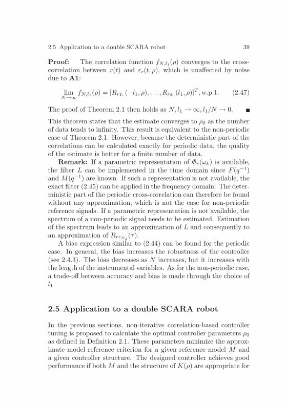
2.5 Application to a double SCARA robot 39
Proof: The correlation function fN,l1(ρ) converges to the cross-correlation between r(t) and εc(t, ρ), which is unaffected by noisedue to A1:
limN→∞
fN,l1(ρ) = [Rrεc(−l1, ρ), . . . , Rrεc
(l1, ρ)]T ,w.p.1. (2.47)
The proof of Theorem 2.1 then holds as N, l1 → ∞, l1/N → 0.
This theorem states that the estimate converges to ρ0 as the numberof data tends to infinity. This result is equivalent to the non-periodiccase of Theorem 2.1. However, because the deterministic part of thecorrelations can be calculated exactly for periodic data, the qualityof the estimate is better for a finite number of data.
Remark: If a parametric representation of Φr(ωk) is available,the filter L can be implemented in the time domain since F (q−1)and M(q−1) are known. If such a representation is not available, theexact filter (2.45) can be applied in the frequency domain. The deter-ministic part of the periodic cross-correlation can therefore be foundwithout any approximation, which is not the case for non-periodicreference signals. If a parametric representation is not available, thespectrum of a non-periodic signal needs to be estimated. Estimationof the spectrum leads to an approximation of L and consequently toan approximation of RrrDd
(τ).A bias expression similar to (2.44) can be found for the periodic
case. In general, the bias increases the robustness of the controller(see 2.4.3). The bias decreases as N increases, but it increases withthe length of the instrumental variables. As for the non-periodic case,a trade-off between accuracy and bias is made through the choice ofl1.
2.5 Application to a double SCARA robot
In the previous sections, non-iterative correlation-based controllertuning is proposed to calculate the optimal controller parameters ρ0
as defined in Definition 2.1. These parameters minimize the approx-imate model reference criterion for a given reference model M anda given controller structure. The designed controller achieves goodperformance if both M and the structure of K(ρ) are appropriate for

40 2 Data-driven controller tuning: an identification problem
Upper arm
Fore-arm
Concentric axes
Wrist
End-effector
Fig. 2.5. FAMMDD double SCARA pick-and-place robot.
the plant. In practice, M and K(ρ) are defined by the user and it isnot straightforward how to choose either of them.
In this section, application of the proposed approach to a pick-and-place robot is discussed. It is shown how the approach can beused to systematically design low-order controllers, starting with thedesign of a high-order FIR controller. An orthogonal basis is thenchosen to approximate the high-order FIR controller by a controllerthat can actually be implemented. If the order of the controller needsto be reduced further, the main characteristics of the high-order con-trollers can be used to define an appropriate structure for K(ρ). Inthis example, all controllers are implemented, but the iterations canalso be performed off-line. An iterative procedure is used to definethe reference model, based on the windsurfing approach for itera-tive control design [3], where the required performance is increasedgradually by increasing the bandwidth of the reference model.
Experimental setup
The pick-and-place robot considered is known as the FAMMDD, Fastand Accurate Manipulator Modules, Direct Drive. This robot isdeveloped at Philips CFT [76]. The main design specification isthat, for relatively simple assembly operations, the robot should be

2.5 Application to a double SCARA robot 41
Wrist
Fore-arm
Upper arm
α1
α2
ℓ
Concentric axes
Fig. 2.6. Schematic representation of FAMMDD.
able to compete with a manual station. The version of the robotin the laboratory of the Control Systems Technology group at theEindhoven University of Technology uses no transmission, hence thename Direct Drive.
The FAMM consists of two SCARAs (Selective Compliant As-sembly Robot Arms), see Figures 2.5 and 2.6. The upper arms arefixed to two concentric axes, and the end-effector is situated at thewrist. The robot is driven by four AC motors, two in the wrist andtwo on the main axis. Only displacements in the horizontal planewill be considered in the experiments, the position of the end-effectorin the wrist is fixed.
Both SCARAs are driven by a servomotor integrated in the axis.Permanent magnets are fixed to the axis, which acts as the rotor ofthe motor. The base of the robot contains the stator coils. An ad-vantage compared to a single SCARA robot is that the mass of themain actuators does not move as the end-effector is displaced. Thearms are designed such that the moving mass is minimized, whilethe required stiffness is maintained. The transmission-free actuationavoids play and other transmission disadvantages, but the load dy-namics are dominant since they are not reduced by a transmissioneither.
The first motor drives the left arm, and affects the angle α1, asshown in Figure 2.6. The second motor drives the right arm, affectingthe angle α2. If both motors are moving in the same direction,

42 2 Data-driven controller tuning: an identification problem
2
»
1 11 −1
–
−1
FAMMDD 1
2
»
1 11 −1
–
G, system after change of variables
-
-
-
-
-
-
-
-
uk2
uk1
um2
um1
α2
α1
ℓ
α
Fig. 2.7. Controlled variables as implemented on the FAMMDD.
α1 − α2 = 0 and the end-effector rotates around the main axis. Ifthe motors move in opposite directions, the distance ℓ of the end-effector from the main axis changes. The load dynamics dependon the position ℓ of the end-effector, thereby resulting in nonlinearbehavior.
Both angles α1 and α2 are measured. The objective is to positionthe end-effector, and the controlled variables are the rotation angleα = (α1 + α2)/2 and ℓ = (α1 − α2)/2. Note that ℓ is a nonlinearfunction of the controlled variable ℓ. The implementation of thischange of variables is shown in Figure 2.7. Outputs of the system areα and ℓ, inputs are uk1 and uk2, and um1 and um2 are the resultinginputs to the first and second motor respectively.
If the distance of the wrist from the main axis, ℓ, is constant, andonly small rotations α around the axes are considered, the system isapproximately linear. In the following experiments, the distance ofthe wrist from the main axis is controlled by Kℓ, a PD controller witha low-pass filter. The controller for the resulting SISO system withinput uk1 and output α is designed using the approach of Section2.4.2.
Experiments
An initial stabilizing controller, Kα, is available and the experimentsare performed in closed loop, according to the scheme of Figure 2.8.Because there is no friction compensation, the experiments are per-formed on the robot in movement. The system is sampled with asampling time of 1 ms. r(t) is a PRBS with a period length of

2.5 Application to a double SCARA robot 43
Kℓ
G
--−
-6f+
−
-αd αuk1
ℓ
- Kα- f -?
r
Fig. 2.8. Closed-loop setup used for controller tuning.
101
102
103
−120
−100
−80
−60
−40
−20
0
Mag
nitu
de [d
B]
Frequency [rad/s]
Fig. 2.9. Measured frequency response function from uk1 to α.
Np = 4095 and amplitude 0.24. A sinusoid of ≈ 0.25 Hz with am-plitude 0.6 radians is applied to αd(t), where the exact frequency ischosen such that the excitation and its harmonics due to nonlineari-ties are located at frequencies in between the frequencies ωk excitedby r(t).
A set of data of length N = 150Np is collected according to thescheme of Figure 2.2. The DFT of these signals is used to calculatea frequency response function of the transfer function from uk1 to α,see Figure 2.9. The first anti-resonance and resonance are situatedaround 150 rad/s.
Correlation-based non-iterative data-driven controllerdesign
At low frequencies, the system behaves as a double integrator. Thefirst reference model M1 is chosen accordingly, such that 1−M1 has

44 2 Data-driven controller tuning: an identification problem
two zeros at 1:
M1 =0.00137q−4 − 0.00135q−5
1 − 3.75q−1 + 5.32q−2 − 3.42q−3 + 0.898q−4 − 0.037q−5.
The bandwidth of M1 lies below the first anti-resonance of the plantand it is expected that this objective can be achieved. Due to theanti-resonances in the system, the ideal controller (2.3) is expectedto show resonant behaviour. In an FIR structure, such resonantbehaviour can only be described if the order of the FIR filter ishigh. An FIR controller of order 1500 is therefore designed using theapproach of Section 2.4.2. It is assumed that the distance betweenK∗ and this high-order FIR controller K(ρ) can be made very small,and that K(ρ) approximates the characteristics of K∗. Since r(t) isa PRBS signal, the extended instruments of (2.29) can be taken as,
ζ(t) = [r(t), r(t − 1), . . . , r(t− l1)]T . (2.48)
F = 1 and l1 = (Np − 1)/2. Note that, since ρ can be determinedanalytically, and Np = 4095, no computational problems are encoun-tered for the calculation of 1500 parameters.
The Bode diagram of the 1500th-order FIR controller is shown inFigure 2.10. The controller contains two poorly damped resonances,one that cancels the first anti-resonance of the plant and a secondone at a higher frequency. This controller cannot be implemented,first of all because the order of the controller is too large. Secondly,even though this controller may achieve perfect model matching forthe measured output α, it is not necessarily a good controller forthe plant. For systems that contain an anti-resonance, cancelationof this anti-resonance may cause oscillations in other (not necessarilymeasured) parts of the system.
A second controller of order 30 is therefore calculated, with anorthogonal basis of Laguerre functions with poles in 0.8. This or-thogonal basis offers many degrees of freedom at low frequencies, andthus permits model matching at the frequencies that are importantfor closed-loop performance. However, the match at high frequenciesis expected to be limited. The Bode diagram of the resulting con-troller is shown in Figure 2.10. The damping of the low-frequencyresonance is larger than that of the FIR controller. As expected, the

2.5 Application to a double SCARA robot 45
101
102
103
−20
0
20
40
60
80
Mag
nitu
de [d
B]
101
102
103
−300
−200
−100
0
100
Pha
se [d
egre
es]
Frequency [rad/s]
Fig. 2.10. Calculated controllers for M1. Grey dashed: FIR of order 1500.Black: Laguerre basis functions of order 30.
101
102
103
−80
−70
−60
−50
−40
−30
−20
−10
0
10
Frequency [rad/s]
Mag
nitu
de [d
B]
Fig. 2.11. Achieved closed-loop performance. Grey dashed: referencemodel M1. Black: measured FRF of the complementary sensitivity with30th-order controller.
controller resembles the FIR controller at low frequencies, but the fitat higher frequencies is limited.
The 30th-order controller is implemented and the same experi-ment as described above is performed with this controller in the loop.The measured response is used to estimate the complementary sen-sitivity function. The achieved closed-loop performance is shown in

46 2 Data-driven controller tuning: an identification problem
101
102
103
−20
0
20
40
60
80M
agni
tude
[dB
]
101
102
103
−300
−200
−100
0
100
Pha
se [d
egre
es]
Frequency [rad/s]
Fig. 2.12. Calculated controllers for M1. Grey dashed: Laguerre basis oforder 30. Black: K1 of order 4
Figure 2.11. The controller structure does not permit perfect modelmatching, but the error is small at all frequencies ranges.
If, for practical reasons, the order of the controller needs to bereduced further, the characteristics of the 1500th- and 30th-ordercontroller can be used to choose an appropriate structure for the low-order controller. In this example, a controller of order 4 is designed,using the data that is measured with the 30th-order controller in theloop. The high-order FIR controller and the 30th-order controllerclearly show the behaviour of a notch filter at about 160 rad/s. Someof the parameters of the low-order controller need to be fixed toreproduce this behaviour. The fixed part of the controller thereforeincludes a notch filter, designed using the response of the 30th-ordercontroller. The remaining two poles are fixed at 0.7. The structureof the controller is given by:
K1(ρ) =(ρ0 + ρ1q
−1 + ρ2q−1)(1 − z1q
−1)(1 − z2q−1)
(1 − p1q−1)(1 − p2q−1)(1 − p3q−1)(1 − p4q−1),
where z1 = z∗2 = 0.98 + 0.15i, p1 = p∗2 = 0.95 + 0.14i and p3 = p4 =0.7. This controller structure cannot cancel the anti-resonance of the

2.5 Application to a double SCARA robot 47
101
102
103
−80
−70
−60
−50
−40
−30
−20
−10
0
10
Frequency [rad/s]
Mag
nitu
de [d
B]
Fig. 2.13. Achieved closed-loop performance. Grey dashed: referencemodel M1. Black: measured FRF of the complementary sensitivity withK1.
system. ζ(t) is defined as (2.48), with l1 = 500 and F = 1. The Bodediagram of the resulting controller is shown in Figure 2.12, where theBode diagram of the 30th-order controller is given for comparison.
The achieved closed-loop performance is shown in Figure 2.13.The controlled system matches the reference model at low frequen-cies, up to the bandwidth of M1. At higher frequencies, the modelcannot be matched due to the limited structure of K1. However,since the controlled system resembles the reference model up to thebandwidth, the tracking performance achieved with this low-ordercontroller is expected to be good. The time response of the con-trolled system is shown in Fig. 2.14. As expected, the response ofthe system follows the response of the reference model reasonablywell. Note that the time responses shown in this section are normal-ized for comparison.
Increasing the bandwidth of the controlled system
The performance requirements can be increased by increasing thebandwidth of the reference model. A second reference model is de-fined as
M2 =0.03211q−4 − 0.03117q−5
1 − 3.01q−1 + 3.36q−2 − 1.68q−3 + 0.34q−4 − 0.013q−5.
A new set of data of length N = 150Np is collected with K1 inthe loop. A low-order controller K2(ρ) is designed, with the same

48 2 Data-driven controller tuning: an identification problem
0 0.05 0.1 0.15 0.2 0.25 0.3 0.35 0.4 0.45 0.5−0.01
0
0.01
0.02
0.03
0.04
0.05
0.06
0.07P
ositi
on [r
ad]
Time [s]
Fig. 2.14. Tracking performance. Dash-dot thin line: reference signalαd. Black: measured response with K1. Grey dashed: response of thereference model M1. Note that the measured response and the responseto M1 are overlapping up to about 0.2 seconds.
101
102
103
−20
0
20
40
60
80
Mag
nitu
de [d
B]
101
102
103
−300
−200
−100
0
100
Pha
se [d
egre
es]
Frequency [rad/s]
Fig. 2.15. Calculated controllers for M2. Black: 4th-order controller K2,calculated according to Section 2.4.2. Dash-dot: 5th-order controller Kls.
structure as that of K1(ρ). ζ(t) is defined according to (2.48), l1 =500 and F = 1.
For comparison, another controller Kls is designed using loopshaping. The non-parametric model of Figure 2.9 is used to designthe controller, and the cross-over frequency is chosen similar to that

2.5 Application to a double SCARA robot 49
ofM/(1−M). A notch filter is introduced to deal with the resonance.This filter is designed using the non-parametric model and is not thesame as the fixed part of K1 and K2. A lead filter is added for thephase margin. A second-order low-pass filter is added to limit thehigh-frequency gain, resulting in a 5th-order controller.
The Bode diagram ofK2 and ofKls are shown in Figure 2.15. Theachieved closed-loop performance is shown in Figure 2.16. Model-matching up to the bandwidth is not possible with the limitedcontroller structure. Since the control objective for K2 is model-matching, it is expected that the achieved model-reference crite-rion Jmr of (2.1) is smaller for K2 than for Kls. Jmr can beapproximated by Jmr(K) =
∑
ωk[M2(e
−jωk) − T (e−jωk)]2, whereT (e−jωk) is the measured FRF as shown in Figure 2.16. As expected,Jmr(K2) = 93.9 < Jmr(Kls) = 104.2. The maximum value of themeasured sensitivity function S(e−jωk) is larger for K2 than for Kls
(not shown). This can be expected since there are no specificationson the robustness margins in model reference control, whereas theloop-shaping controller Kls satisfies a specification on the modulusmargin.
The time-domain response of the controlled plant is shown inFigure 2.17. Note that the measured response of the plant controlledby Kls cannot be distinguished from the overlapping response of theplant controlled by K2. The response of the plant controlled by K2
is thus comparable to that of the plant controlled by Kls. Note alsothat the reference signal αd in Figure 2.17 is the same as αd in Figure2.14. The response of M2 is much faster than the response of M1
and the response of the reference model is almost superposed on αd.The achieved tracking performance of K2 is thus comparable to
the tracking achieved by the loop-shaping controller Kls. The Bodediagram of K2 and that of Kls are also very similar. This resultmight not be surprising for such low-order controllers. However, itshould be noted that the structure of K2 is found systematically froma series of optimization problems, and the proposed approach can beused to calculate the optimal controller for any predefined controllerstructure and order. If a higher order controller can be implementedin practice, the achieved performance is improved, as illustrated bythe results achieved with the 30th-order controller, shown in Figure2.11.

50 2 Data-driven controller tuning: an identification problem
101
102
103
−80
−70
−60
−50
−40
−30
−20
−10
0
10
Frequency [rad/s]
Mag
nitu
de [d
B]
Fig. 2.16. Achieved closed-loop performance. Grey dashed: referencemodel M2. Black: measured FRF of the complementary sensitivity withK2. Black dash-dot: measured complementary sensitivity with 5th-orderKls.
0 0.05 0.1 0.15 0.2 0.25 0.3 0.35 0.4 0.45 0.5−0.01
0
0.01
0.02
0.03
0.04
0.05
0.06
0.07
Pos
ition
[rad
]
Time [s]
Fig. 2.17. Tracking performance. Dash-dot thin line: reference signal αd.Black: measured response with 4th-order K2. Black dash-dot: measuredresponse with 5th-order Kls. Grey dashed: response of the reference modelM2.
2.6 Conclusions
In this chapter, an approximate model reference criterion is defined,and straightforward schemes are proposed that can be used to iden-tify the controller that minimizes this approximate model referencecriterion. The resulting controller identification problem is analyzed.Two cases are considered. In the first case it is assumed that per-fect model matching can be achieved with the predefined controllerstructure. It is shown that, in this case, the controller identifica-tion problem corresponds to an identification problem with a spe-

2.6 Conclusions 51
cific noise model, where the noise model depends on the controllerparameters. In the second case, it is assumed that the structure ofthe controller does not allow perfect model matching and that a biaserror exists between the ideal controller and the optimal controller.It is shown that, in the presence of measurement noise, a controlleridentified using prediction error methods does not converge to theoptimal controller.
The use of the correlation approach is proposed to deal with theeffect of noise in the controller identification problem. It is shownthat the estimated controller converges to the optimal controller,also if perfect model matching cannot be achieved. Both periodicand non-periodic excitation signals are considered and the approachis applicable to both stable and unstable systems. A closed-loopexperiment is proposed for unstable systems. This closed-loop ap-proach has been applied to a pick-and-place robot.


3
Data-driven controller tuning with
guaranteed stability
There is no guarantee that a controller determined by minimizing themodel reference criterion Jmr(ρ) or its approximation J(ρ) actuallystabilizes the plant. Instability can occur if the reference model ischosen inappropriately or if the measurements are strongly affectedby noise. The ideal controller K∗ is defined indirectly from G andM as shown in (2.3). Whether K∗ stabilizes the plant depends onboth the plant G and the choice of reference model M . If the plant isnonminimum phase, internal stability can only be guaranteed whenM contains the unstable zeros of G. This clearly makes the choiceof an appropriate M difficult in a data-driven approach.
Even if the ideal controller K∗ stabilizes the plant, this is notnecessarily the case for the optimal controller K(ρ0) (see [31] for anexample where K∗ was not in the controller set). Furthermore, if theoptimal controller K(ρ0) stabilizes the plant, an estimate of K(ρ0)based on noisy data might not be stabilizing.
Instability due to an inappropriate reference model is not specificto data-driven methods, it is inherent to model reference control.In the following, a constraint is proposed that can be added to themodel reference optimization problem, or to its approximation. Theoptimizer of the constrained problem is guaranteed to stabilize theplant.
Implementation of the constraint in a data-driven setting is dis-cussed in Section 3.2 and 3.3. It is shown that, for linearly param-eterized controllers, an estimate of the stability condition leads to

54 3 Data-driven controller tuning with guaranteed stability
a set of convex constraints. These constraints can be added to anydata-driven controller tuning scheme. In Sections 3.2 and 3.3, theconstraints are added to the correlation approach of Section 2.4.
3.1 Model reference control with guaranteed
stability
In the following, a sufficient condition is defined for closed-loop sta-bility of the plant G controlled by the controllerK(ρ). This conditionis based on the existence of a stabilizing controller Ks. The sensi-tivity and complementary sensitivity function of the plant controlledby this Ks are used to define the stability condition. However, inorder to verify the condition, this Ks does not need to be known. InSection 3.2 it is shown how, for stable minimum-phase plants, thecondition can be verified using the reference model and data from anopen-loop experiment. For unstable or nonminimum-phase plants,data from a specific closed-loop experiment are sufficient to verifythe condition, as shown in Section 3.3.
Consider the stabilizing controller Ks. The closed-loop plant forthis controller is given by:
Ms =KsG
1 +KsG(3.1)
The closed-loop system with controller K(ρ) can be represented asillustrated in Figure 3.1.
Define ∆(ρ) := Ms − K(ρ)G (1 −Ms) and its infinity normδ(ρ) := ‖∆(ρ)‖∞.
Theorem 3.1 The controller K(ρ) stabilizes the plant G if
1. ∆(ρ) is stable2. ∃δN ∈ ]0, 1[ such that δ(ρ) 6 δN
Proof: If Condition 1 is satisfied, all transfer functions of the loopopened at q are stable, since Ks stabilizes the plant, i.e. the transferfunctions from r(t), v(t) and q(t) to e(t), y(t), u(t) and q(t) are stable.The sufficient condition for stability of the closed-loop interconnec-tion follows from the small-gain theorem [85] : the interconnectionis stable if

3.1 Model reference control with guaranteed stability 55
Ks Gii i- - - - - -
6
K(ρ) − Ks-
? ?r
q
u y
v
e
-
+ +
Fig. 3.1. Closed-loop system with controller K(ρ) and explicit represen-tation of the controller error K(ρ) − Ks
∥
∥
∥
∥
−(K(ρ) −Ks)G
1 +KsG
∥
∥
∥
∥
∞
< 1 (3.2)
This is the H∞-norm of the transfer function from q back to q. Re-placing KsG
1+KsG by Ms and 11+KsG by 1 −Ms gives
∥
∥
∥
∥
−(K(ρ) −Ks)G
1 +KsG
∥
∥
∥
∥
∞
= δ(ρ).
Theorem 3.1 thus follows from the small-gain theorem. Similar con-ditions for stability have been used for controller reduction (see forexample [86], p. 491).
Condition 1 is satisfied if the controller K(ρ) is stable, but un-stable controllers can also satisfy Condition 1. Consider for exam-ple a controller with an integrator. The transfer function ∆(ρ) =Ms −K(ρ)G (1 −Ms) is stable if G(1 −Ms) contains a zero at 1.
This sufficient condition for closed-loop stability can be used toguarantee a stabilizing solution to the model reference problem ofSection 2.1.
Definition 3.1 (Stabilizing controller) Let the controller be pa-rameterized as in (2.7) and J(ρ) given by (2.6). Let Condition 1 fromTheorem 3.1 be satisfied. The parameters ρs of the stabilizing con-troller K(ρs) are given by the optimum of the following constrainedconvex optimization:

56 3 Data-driven controller tuning with guaranteed stability
ρs = arg minρ∈DK
J(ρ)
subject to δ(ρ) 6 δN(3.3)
In the following, a data-driven approach is presented that com-bines minimization of the estimate JN,l1(ρ) and a set of constraintsthat estimate the bound δ(ρ). The estimation errors can be takeninto account through the choice of δN , as shown in Section 3.5.
3.2 Data-driven approach for stable
minimum-phase systems
Theorem 3.1 is based on the small-gain theorem and requires theclosed-loop system Ms to be internally stable. For stable minimum-phase plants, any stable reference model M defines the ideal con-troller K∗ according to (2.3) that internally stabilizes the system.The reference model can therefore be used to define the sufficientcondition for stability.
Lemma 3.1 Let Ms be given by M . The controller K(ρ) stabilizesthe stable minimum-phase plant G if ∆(ρ) = Ms−K(ρ)G(1−Ms) =M −K(ρ)G(1 −M) is stable and ∃δN ∈ ]0, 1[ such that
δ(ρ) = ‖Ms −K(ρ)(1 −Ms)G‖∞= ‖M −K(ρ)(1 −M)G‖∞ 6 δN (3.4)
Proof: Follows from Theorem 3.1 upon replacing Ks by the sta-bilizing ideal controller K∗.
Remark: Through the definition of K∗ given in (2.3), K∗ mightbe non-causal, but K∗G is always causal. The small-gain theoremrequires causality because algebraic loops will occur for non-causalfunctions. However, since K∗G is always causal, no algebraic loopoccurs in the interconnection of Figure 3.1 and Lemma 3.1 remainsvalid.
If the plant G or the controller K(ρ) contains one or several inte-grators, the above scheme remains applicable provided the referencemodel is chosen with care. Let ni be the number of integrators inthe loop function KG. It is then easily verified that ∆(ρ) is stable if

3.2 Data-driven approach for stable minimum-phase systems 57
1 −M has nz > ni zeros at 1. The reference model M needs to bechosen such that this condition is satisfied. Note that, if ni = 1, allreference models with unity static gain satisfy this condition.
For stable minimum-phase plants, the optimization in Definition3.1 can thus be replaced by
ρs = arg minρ∈DK
J(ρ)
subject to
‖M −K(ρ)(1 −M)G‖∞ 6 δN
(3.5)
Remark: Condition (3.4) is sufficient but not necessary andtherefore conservative. The optimal controller K(ρ0) might stabi-lize the system but not meet condition (3.4). However, this indicatesthat the distance between K(ρ) and K∗ cannot be made small. Inthis case, the approximate model reference criterion (2.6) is not agood approximation of (2.1).
In a data-driven approach, the available signals from the schemeof Figure 2.1 can be used to estimate δ(ρ). Define
εs(t, ρ) := Mr(t) −K(ρ)(1 −M)y(t)
=[
M −K(ρ)(1 −M)G]
r(t) −K(ρ)(1 −M)v(t) (3.6)
Note that the transfer function between r(t) and εs(t, ρ) is equalto ∆(ρ). Hence, the available signals r(t) and εs(t, ρ) can be used toestimate δ(ρ). It will be shown that a spectral estimate leads to aset of convex constraints on the controller parameters ρ.
In Chapter 2, the open-loop scheme can be used for both mini-mum and nonminimum-phase stable systems. However, Lemma 3.1is not valid for nonminimum-phase stable systems, and the closed-loop scheme of Section 3.3 needs to be used.
Implementation using spectral estimates
In the following, it is shown that a spectral estimate of δ(ρ) definesa set of convex constraints. These constraints are added to the cor-relation approach presented in Section 2.4.1. Let the plant G beexcited by r(t) as illustrated in Figure 2.1. The output of the plant

58 3 Data-driven controller tuning with guaranteed stability
is affected by noise, y(t) = Gr(t) + v(t). The signals r(t) and y(t) oflength N are available and assumed to satisfy A1-A4. The correla-tion criterion JN,l1(ρ) is given by (2.31).
An estimate of δ(ρ) based on spectral estimates is given by:
δ(ρ) = maxωk
∣
∣
∣
∣
∣
Φrεs(ωk, ρ)
Φr(ωk)
∣
∣
∣
∣
∣
, (3.7)
where Φr(ωk) is an estimate of the spectrum of r(t) for ωk =2πk/(2l2 + 1), where k = 0, . . . , l2 + 1:
Φr(ωk) =
l2∑
τ=−l2
Rr(τ)e−jτωk ,
and Rr(τ) is an estimate of the auto-correlation Rr(τ) of r(t):
Rr(τ) =1
N
N∑
t=1
r(t − τ)r(t), for τ = −l2, . . . , l2, (3.8)
where l2 defines the length of the rectangular window. Φrεs(ωk, ρ) is
an estimate of the cross-spectrum between r(t) and εs(t, ρ):
Φrεs(ωk, ρ) =
l2∑
τ=−l2
Rrεs(τ, ρ)e−jτωk ,
using an estimate of the cross-correlation Rrεs(τ, ρ):
Rrεs(τ, ρ) =
1
N
N∑
t=1
r(t − τ)εs(t, ρ), τ = −l2, . . . , l2.
Note that, although a rectangular window is used here, other win-dows can also be used.
Using the controller parameterization (2.7), Φrεs(ωk, ρ) can be
expressed as a linear combination of the controller parameters:
Φrεs(ωk, ρ) =
1
N
l2∑
τ=−l2
N∑
t=1
[
r(t− τ)Mr(t)e−jτωk
− r(t − τ)βT (1 −M)y(t)e−jτωkρ]
. (3.9)

3.2 Data-driven approach for stable minimum-phase systems 59
The estimate (3.7) can thus be used to define a set of convex con-straints such that δ(ρ) 6 δN . An approximation of (3.5) is givenby:
ρ = arg minρ∈DK
JN,l1(ρ)
subject to∣
∣
∣
∣
l2∑
τ=−l2
Rrεs(τ, ρ)e−jτωk
∣
∣
∣
∣
6 δN
∣
∣
∣
∣
l2∑
τ=−l2
Rr(τ)e−jτωk
∣
∣
∣
∣
,
ωk = 2πk/(2l2 + 1), k = 0, . . . , l2 + 1
(3.10)
Note that, in contrast to the unconstrained problem of Section 2.4,this optimization cannot be solved analytically. Both the objectivefunction and the constraints in (3.10) are differentiable and the con-strained optimization can be solved numerically. The problem canbe solved for up to several thousand constraints and the solution isthe global optimum.
Theorem 3.2 Consider the controller structure defined in (2.7).Let the stable filter L be defined as:
L(e−jω) =F (e−jω)(1 −M(e−jω))
Φr(ω)(3.11)
Assume that A1-A4 are satisfied, that L(1−M)G has no zero on theimaginary axis and that a strictly feasible solution exists for (3.10),for the series of optimization problems as N, l1, l2 → ∞ as well asfor (3.5). Then, as N, l1, l2 → ∞ and l1/N, l2/N → 0, the optimizerρ in (3.10) converges w.p.1 to the stabilizing optimizer ρs of J(ρ)defined in (3.5):
limN,l1,l2→∞,l1/N,l2/N→0
ρ = ρs, (3.12)
Proof: Convergence of the unconstrained problem w.p.1 followsfrom Theorem 2.1. As N, l1 → ∞, l1/N → 0 the correlation criterionJN,l1(ρ) → J(ρ) and the convergence is uniform on DK .
As N → ∞, l2/N → 0, the estimate Rrεs(τ, ρ) converges w.p.1 to
Rrεs(τ, ρ) and Rr(τ) converges w.p.1 to Rr(τ), for τ = [−l2, . . . , l2].

60 3 Data-driven controller tuning with guaranteed stability
Consequently Φrεs (ωk,ρ)
Φr(ωk)converges pointwise to ∆(ωk), w.p.1. ∆(ωk)
and δ(ρ) are bounded on DK since ∆ is stable. The series of con-vex functions maxωk
|∆(ωk)| then converges uniformly to the convexfunction δ(ρ) as l2 → ∞ (Theorem 10.8 of [69]). It follows that,
with probability 1, maxωk
∣
∣
∣
Φrεs (ωk,ρ)
Φr(ωk)
∣
∣
∣converges uniformly to δ(ρ) as
N, l2 → ∞, l2/N → 0.Convergence of the constrained optimization then follows from
the dual problem (Theorem 1.44 [13]): Consider the function L(ρ) :=J(ρ) + ν(δ(ρ) − δN ), where ν is Lagrange multiplier and (ν0, ρ0) isa KKT (Karush-Kuhn-Tucker) point of L(ρ). Then ρ0 is the global
optimizer of (3.5). Since JN,l1(ρ) and maxωk
∣
∣
∣
Φrεs (ωk,ρ)
Φr(ωk)
∣
∣
∣converge
uniformly to J(ρ) and δ(ρ), the dual of (3.10) converges uniformly toL(ρ). Since the convergence is uniform, it follows that the optimizerof (3.10) converges to the optimizer of (3.5).
Implementation for periodic data
It is well known that the quality of spectral estimates can be im-proved when periodic data is used [54]. Periodic excitation shouldtherefore be used whenever possible. The use of periodic data alsoimproves the quality of the correlation criterion estimate (see Section2.4.4). The trade-off for this improved quality is a limited frequencyresolution.
Assume that A1, A2, A5 and A6 are satisfied. The lengthof the instrumental variable vector ζ(t) of (2.29) is chosen as l1 6(Np − 1)/2. The correlation criterion JN,l1(ρ) is defined in (2.31).
The auto-correlation of the periodic reference r(t) can be cal-culated using (2.15). According to assumption A6, the spectrumis nonzero for ωk = 2πk/Np, k = 0, . . . , Np − 1. Due to symme-try, it is completely defined by half of the frequencies, i.e. ωk =2πk/Np, k = 0, . . . , ⌊(Np − 1)/2⌋. Let the error signal εs(t, ρ) begenerated periodically, i.e. no transients are present in the response.The cross-spectrum can be estimated for the same frequencies ωk:
Φrεs(ωk, ρ) =
Np−1∑
τ=0
Rrεs(τ, ρ)e−jτωk , (3.13)

3.2 Data-driven approach for stable minimum-phase systems 61
where Rrεs(τ, ρ) is given by:
Rrεs(τ, ρ) =
1
N
N∑
t=1
r(t− τ)εs(t, ρ), τ = 0, . . . , Np − 1. (3.14)
The spectral estimate
δ(ρ) = maxωk
∣
∣
∣
∣
Φrεs(ωk, ρ)
Φr(ωk)
∣
∣
∣
∣
(3.15)
can be used to define a set of convex constraints. This estimatedoes not contain leakage errors and has a decreasing variance withincreasing number of periods [54]. For periodic signals, the optimiza-tion problem (3.5) can be approximated by:
ρ = arg minρ∈DK
JN,l1(ρ)
subject to∣
∣
∣
∣
Np−1∑
τ=0
Rrεs(τ, ρ)e−jτωk
∣
∣
∣
∣
6 δN
∣
∣
∣
∣
Np−1∑
τ=0
Rr(τ)e−jτωk
∣
∣
∣
∣
,
ωk = 2πk/Np, k = 0, . . . , ⌊(Np − 1)/2⌋
(3.16)
⌊·⌋ denotes the closest integer below.
Theorem 3.3 Consider the controller structure defined in (2.7).Let the stable filter L be defined for the frequencies ωk where thespectrum Φr(ωk) is nonzero:
L(e−jωk) =F (e−jωk)(1 −M(e−jωk))
Φr(ωk)(3.17)
Assume that A1, A2, A5 and A6 are satisfied, that L(1 −M)Ghas no zero on the imaginary axis and that a strictly feasible so-lution exists for (3.16), for the series of optimization problems asN, l1, Np → ∞ as well as for (3.5). Then, as N,Np, l1 → ∞ andNp/N → 0, the optimizer ρ of (3.16) converges w.p.1 to the stabiliz-ing optimizer of J(ρ) defined in (3.5):
limN,Np,l1→∞,Np/N→0
ρ = ρs (3.18)
Proof: Follows from Theorem 2.3 and Theorem 3.2 .

62 3 Approach for nonminimum-phase or unstable systems
3.3 Data-driven approach for nonminimum-phase
or unstable systems
For nonminimum-phase or unstable plants, an arbitrary referencemodel M does not define a stabilizing ideal controller K∗. For suchplants, Lemma 3.1 is not applicable, and the optimization of (3.3)needs to be used instead of (3.5). In (3.3), the control criterionJ(ρ) is defined using the (arbitrary) reference model M , whereasthe constraint for stability uses Ms. If a stabilizing controller Ks isavailable, the closed-loop interconnection of G and Ks represents Ms
given in (3.1). In order to estimate δ(ρ), a set of input-output dataof the transfer function Ms −K(ρ)(1 −Ms)G is sufficient.
Consider the tuning scheme of Figure 2.2. Define
εs(t, ρ) := −u1(t) −K(ρ)y(t)
=(
Ms −K(ρ)(1 −Ms)G)
r(t) + (Ks −K(ρ))(1 −Ms)v(t) (3.19)
The transfer function between r(t) and εs(t, ρ) is equal to ∆(ρ), andthe signals available from the scheme of Figure 2.2 can be used toestimate δ(ρ).
Remarks:
• In the case of stable minimum-phase plants, the fact that theconstraint in (3.5) is active indicates that the model referencecriterion was inappropriate. This is no longer the case for theclosed-loop scheme of Figure 2.2, where violation of the constraintin (3.3) simply implies that closed-loop stability cannot be guar-anteed, because the distance between the controller K(ρ) andthe stabilizing controller Ks is not small. This result agrees withideas from iterative identification and control, e.g. [3,53]. In [53],the term “safe controller change” is used to denote an acceptablecontroller change that ensures a certain stability margin. Theidea is that, by limiting the change in the controller, one can alsolimit the degradation that can occur in the actual closed-loopsystem.
• A test that uses experimental closed-loop data to verify whethera controller stabilizes the plant is proposed in [50]. The methoduses coprime factorization and can handle unstable systems as

3 Approach for nonminimum-phase or unstable systems 63
well as unstable controllers. In the specific case of a stable con-troller, the experiment proposed in [50] corresponds to the schemeof Figure 2.2. The transfer function considered in our stabilitycriterion is the same as the transfer function considered in thestability test in [50]. However, the stability tests are different.In [50], both phase and amplitude are taken into account. TheNyquist stability criterion then leads to a non-conservative test,which corresponds to verifying whether Ms−K(ρ)(1−Ms)G doesnot encircle the point −1 in the complex plane. A frequency-domain model of Ms −K(ρ)(1 −Ms)G is identified and used forverification. In this work, the stability criterion uses the small-gain theorem, which leads to a conservative result. However, theresulting H∞-norm constraint is convex and can be added to aconvex controller optimization. The non-conservative test usingboth amplitude and phase information would lead to non-convexconstraints.
Implementation using spectral estimates
Let the unstable plant G be excited by r(t) in closed loop accordingto the scheme of Figure 2.2. The output of the plant is affected by thenoise v(t). The discrete signals r(t), y(t), u1(t) and u2(t) of length Nare available. The error εc(t, ρ) is given by (2.11) and the correlationcriterion JN,l1(ρ) is defined in (2.31). The error signal εs(t, ρ) usedin the stability constraints is given by (3.19). Optimization problem(3.3) can be approximated by (3.10).
Theorem 3.4 Consider the controller structure defined in (2.7).Let the stable filter L be defined as:
L(e−jω) =F (e−jω)(1 −M(e−jω))(
1 −Ms(e−jω))
Φr(ω)(3.20)
Assume that A1-A4 are satisfied, that L(1−M)G/(1+KsG) has nozero on the imaginary axis and that a strictly feasible solution existsfor (3.3), for the series of optimization problems as N, l1, l2 → ∞as well as for (3.10). Then, as N, l1, l2 → ∞ and l1/N, l2/N → 0,the optimizer ρ in (3.10) converges w.p.1 to the stabilizing optimizerJ(ρ) as defined in (3.3):

64 3 Approach for nonminimum-phase or unstable systems
limN,l1,l2→∞,l1/N,l2/N→0
ρ = ρs. (3.21)
Proof: Even though G might be unstable, the filter (1 −Ms)G isstable and consequently all filters involved are stable and all signalsare bounded. The proof then follows from the proof of Theorem 2.2and Theorem 3.2.
As discussed in Section 2.4.2, the filter L depends on the un-known plant G and cannot be implemented. However, it can be ap-proximated by (2.41). As for the scheme for stable minimum-phasesystems, the quality of the estimates can be improved by using peri-odic data. The implementation for the closed-loop scheme is similarto the implementation for the open-loop scheme and therefore notdetailed here.
3.4 Alternative implementation using Toeplitz
matrices
In the method proposed in this thesis, anH∞ specification is added tothe controller tuning using the DFT. Similar H∞ specifications havebeen used in system identification [64] and data-driven controllertuning [47] as well as in the stability test introduced in [82]. In thesemethods, non-periodic signals are considered, and the constraint onthe H∞-norm is defined using Toeplitz matrices, which leads to aLinear Matrix Inequality (LMI).
The method proposed here is closely related to Toeplitz-basedmethods. In the case of periodic signals, the method is equivalentto using circulant matrices, and constraints (3.16) can be imposedas an LMI. In order to show this, some results on circulant matricesare summarized first.
A circulant matrix is defined for x(t) as
C(x) =
x(1) x(2) . . . x(N − 1) x(N)x(N) x(1) . . . x(N − 2) x(N − 1)
......
. . ....
...x(3) x(4) . . . x(1) x(2)x(2) x(3) . . . x(N) x(1)

3.4 Alternative implementation using Toeplitz matrices 65
where each row is a cyclic shift of the row above it. Some character-istics of circulant matrices are as follows [22]:
1. Consider two circulant matrices C(x) and C(z), then C(x)C(z) =C(z)C(x), C(x)+C(z), C−1(·) and CT (·) are also circulant ma-trices.
2. The eigenvalues of a circulant matrix of size N are given by :
λk(C(x)) =
N∑
t=1
x(t)e−itωk , ωk = 2πk/N, k = 0, . . . , N − 1
(3.22)3. The eigenvectors of a circulant matrix of size N are given by:
Uk =1√N
(
1, e−iωk , e−i2ωk , . . . , e−i(N−1)ωk
)
(3.23)
Note that the eigenvectors are independent of the elements of thematrix.
4. Define the matrix U , which has the eigenvectors Uk, k =0, . . . , N−1, as columns, and define Λ(·) = diag(λk(C(·)). Then,U is full rank and unitary, i.e. UU∗ = I and U∗U = I. For eachcirculant matrix C(·):
Λ(·) = U∗C(·)U (3.24)
Lemma 3.2 For two N ×N circulant matrices C(x) and C(z):
CT (x)C(x) − CT (z)C(z) 6 0 ⇐⇒|λk(C(x))| − |λk(C(z))| 6 0, k = 0, . . . , N − 1 (3.25)
Proof: The proof follows from U being full rank:
CT (x)C(x) − CT (z)C(z) 6 0 ⇐⇒U∗(
CT (x)C(x) − CT (z)C(z))
U 6 0 ⇐⇒Λ(x)∗Λ(x) − Λ(z)∗Λ(z) 6 0 ⇐⇒|λk(C(x))| − |λk(C(z))| 6 0, k = 0, . . . , N − 1
The third expression follows from (3.24) and the last one from thedefinition of Λ(·).

66 3 Approach for nonminimum-phase or unstable systems
Ct(·) is defined as a truncated circulant matrix of size N×T . Themultiplication of two truncated matrices CT
t (·)Ct(·) is a circulantmatrix of size T × T .
The main result is now presented in the following theorem.
Theorem 3.5 The convex constraints in (3.16) are equivalent to thefollowing LMI:
[
−δ2NCTt (r)Ct(r)C
Tt (r)Ct(r) CT
t (r)Ct(εs(ρ))CT
t (εs(ρ))Ct(r) −I
]
6 0 (3.26)
Proof:CT
t (εs(ρ))Ct(r) = C(NRrεs(τ, ρ)) (3.27)
where Rrεs(τ, ρ) is given by (3.15) for τ = 0, . . . , Np − 1. Its eigen-
values are given by:
λk
(
C(NRrεs(τ, ρ))
)
= NΦrεs(ωk, ρ) (3.28)
Equivalently,λk
(
CTt (r)Ct(r)
)
= NΦr(ωk) (3.29)
Then, using Lemma 3.2, one can write:
CTt (εs(ρ))Ct(r)C
Tt (r)Ct(εs(ρ)) − δ2NC
Tt (r)Ct(r)C
Tt (r)Ct(r) 6 0
⇐⇒ |Φrεs(ωk, ρ)| − δN |Φr(ωk)| 6 0,
ωk = 2πk/Np, k = 0, . . . , (Np − 1) (3.30)
Using the Schur complement, the LMI (3.26) is obtained.
Remark: Constraint (3.26) can be seen as a periodic version ofthe norm proposed in [31]. The direct use of the DFT instead of thesecirculant matrices has two advantages. First of all, the computationalload is much smaller. Secondly, the frequencies considered can bechosen in a straightforward manner. For example, only frequencieswhere the signal-to-noise ratio is reasonable could be selected.
3.5 Guaranteeing stability for a finite number of
data
In practice, the constraint δ(ρ) used for controller tuning in the op-timization problem of (3.10) is an estimation of δ(ρ). Consequently,

3.5 Guaranteeing stability for a finite number of data 67
stability can only be guaranteed if the estimation errors are takeninto account. Next, a stochastic approach that leads to a (conserva-tive) probabilistic bound is considered.
In the following, r(t) is assumed to satisfy A5 and A6. The noiseis assumed to satisfy A1-A2. Furthermore, assume that:
• there exists a finite pair of reals A, γ ∈ R, γ < 1, such that|d(k)| 6 Aγk, for k ∈ Z+, where d(k) is the impulse response of∆.
A and γ are in general not known beforehand and might need to beverified a posteriori.
Implementation using spectral estimates
The estimate (3.15) contains an error term due to the estimationerror of ∆(e−jωk) at the frequencies ωk and a second error term dueto the finite frequency grid.
Estimation error at ωk. It follows from Assumption A5 that thetruncation error is zero and the error of ∆(e−jωk) is entirely dueto measurement noise.
Error due to finite frequency grid. The maximum of |∆(e−jω)|might be situated in between two consecutive frequencies ωk andωk+1. This error due to the finite frequency grid depends on the
derivative of |∆(e−jω)| with respect to ω, i.e. d|∆(e−jω)|dω , and the
distance between two consecutive frequencies.
If both errors are taken into account in the bound δN , stability isguaranteed also for finite data length. Define Φr,min as the minimalvalue of the spectrum Φr(ωk) at the frequencies ωk = 2πk/Np, k =0 . . .Np − 1.
Theorem 3.6 The controller K(ρ) stabilizes the plant G, with prob-ability p, if
∣
∣
∣
∣
∣
Φrεs(ωk, ρ)
Φr(ωk)
∣
∣
∣
∣
∣
< δN , for ωk =2πk
Np, k = 0 . . .Np − 1,

68 3 Approach for nonminimum-phase or unstable systems
where
δN = 1 − Aγ
(1 − γ)2π
Np− ‖(1 −M)K(ρ)‖∞
√
− ln(1 − p)‖Hv‖2
∞ σ2
npΦr,min.
Proof: See Appendix A.2
Note that the bound δN depends on the unknown parameters ρ.‖(1 −M)K(ρ)‖∞ can be implemented using an LMI and (3.16) re-mains convex.
The bound presented in Theorem 3.6 represents a worst-case er-ror in between frequencies. Furthermore, the error due to noise isbased on inequalities. The bound is therefore conservative. Less con-servative bounds can be formulated, based on the exact same data, ifan FIR model is used that corresponds to the spectral estimates [14].
Implementation using finite impulse response model
Define the response of ∆ to a periodic signal with period length Np
as:
dper(t) = d(t) +
∞∑
i=1
d(t+ iNp), t = [0, . . . , Np − 1].
Define the vector
dper = [dper(0), dper(1) . . . dper(Np − 1)]
An FIR estimate of d(t) of length Np is given by:
θ = [ΨΨT ]−1Ψεs (3.31)
where
Ψ = [ψ(1), ψ(2), . . . , ψ(N)]
ψ(t) = [r(t), r(t − 1) . . . r(t−Np + 1)]T
εs = [εs(1) . . . εs(N)]T
εs(t) is defined in (3.6) and can be written as
εs(t) = ∆r(t) + (1 −M)K(ρ)v(t).

3.5 Guaranteeing stability for a finite number of data 69
The deterministic part of εs(t) is given by ∆r(t) = ψT (t)dper .Since the noise is uncorrelated with the reference,
Eθ = E[ΨΨT ]−1Ψεs = dper .
It is easily verified that
Ψεs = [Rrεs(0), . . . , Rrεs
(Np − 1)],
and that the FIR estimate θ is the deconvolution of Rrεs(τ) and
Rr(τ). This is the inverse Fourier transform of ∆(e−jωk , ρ), for ωk =
2πk/Np, k = 0, . . . , Np − 1. The estimate θ is thus the time-domainequivalent of ∆(e−jωk , ρ).
The estimate θ can be used to define a constraint on the gain ofthe error function that is defined over all frequencies:
∆(e−jω, ρ) =
Np−1∑
t=0
θ(t)e−jωt = Γ T (e−jω)θ, (3.32)
where Γ (e−jω) = [1, e−jω, e−j2ω, . . . , e−j(Np−1)ω]T . The constraint‖∆‖∞ < 1 can be implemented using an LMI based on a state-space representation of the FIR model ( [8], chapter 2, bounded reallemma). This constraint is convex.
In [14], it is shown that the choice of the length of the FIR modelintroduces a trade-off between the bias and the noise error. The opti-mal length, for which the tightest bounds can be defined, depends onthe system and the noise characteristics. The noise error is estimatedusing the data and the bias error also contains transition errors. Inthe following, a simplified bound is proposed. Only models with anFIR length equal to the period Np are considered here. The resultsare based on a priori information on the system and noise, and thebounds are relatively simple to implement.
Theorem 3.7 The controller K(ρ) stabilizes the plant G with prob-ability p, if
‖∆‖∞ < δN , for ωk =2πk
Np, k = 0 . . .Np − 1,

70 3 Approach for nonminimum-phase or unstable systems
where
δN = 1 − 2
(
AγNp
1 − γ
)
− ‖(1 −M)K(ρ)‖∞
√
− ln(1 − p)‖Hv‖2
∞ σ2
npΦr,min.
Proof: See Appendix A.3
This error bound is tighter that of Theorem 3.6 and is therefore lessconservative. However, this approach uses the H∞ norm based on anFIR model, which leads to a large LMI, for which the computationalload is considerable.
3.6 Illustrative examples
3.6.1 Numerical example: delay system
A simple example was used in [31] to show that stability problemsoccur “for the class of identification-for-control methods that use ar-bitrary data in the identification”. The same example will be usedhere to show that the method proposed in this thesis leads to stabi-lizing controllers.
The pure time-delay system G(q−1) = q−1 is considered. Theproportional controller K = ρ is used to control the plant. Thecontrolled system is unstable for |ρ| > 1. The reference model isM = 1−α+αq−1, where α is a parameter controlling the bandwidth.The model-reference control problem is minimized by K(ρ0) = ρ0 =4α−16α . For 0 < α < 0.1, |ρ0| > 1, and the controlled system will be
unstable.The system is excited by a periodic PRBS with period Np =
63 and np = 4 periods. The reference model is chosen as M =0.95 + 0.05q−1, i.e. with α = 0.05 for which the optimal controllerK(ρ0) = −2.67 destabilizes the plant. Two controllers are calculatedusing noise-free simulation data. The first controller is calculatedwithout the stability constraints in (3.16). The controller found isK(ρ1) = −2.67, which destabilizes the system. The second controlleris calculated using (3.16) with δN = 0.999. This optimization isinfeasible. A closer look at the bound shows that δ = ‖M −K(1 −M)G‖∞ = 1 for all stabilizing controllers and the problem is indeed

3.6 Illustrative examples 71
infeasible. The controller design was poorly formulated through aninappropriate choice of M .
In order to show the effectiveness of the method in the pres-ence of noise, the reference model used for the stability constraintsis slightly altered, Ms = 1 − α + 0.95αq−1. The reference modelused in the control objective remains unchanged. For this problemδ = ‖Ms − K(ρ)(1 − Ms)G‖∞ < 1 for a subset of the stabilizingcontrollers and the problem is thus feasible. The output of the sys-tem is perturbed by a white noise such that the signal-to-noise ratiois about 10 in terms of variance. The controller obtained withoutusing the constraints in (3.16) is K(ρ1) = −2.34, which again desta-bilizes the system. The second controller calculated using (3.16) isK(ρ2) = −0.33. Clearly, since |K(ρ2)| < 1, it stabilizes the system.The difference between K(ρ1) and K(ρ2) indicates a poor problemformulation.
The alternative implementation using circulant matrices leads toa large LMI, which becomes expensive to compute for large datalength. The following comparison is found using Matlab V 7.4 on aMac with a 3 GHz processor and 5 GB memory. The optimizationis implemented using Yalmip [55] and SeDuMi [78]. The aforemen-tioned problem for N = 252 leads to exactly the same result usingboth implementations. The DFT approach is more expensive toformulate but faster to run. The difference is small for small datalengths, e.g. for Np = 63, N = 252 the DFT approach takes 0.7s vs.2s for the LMI. For Np = 127, N = 1016, the DFT approach takes2.2s vs. 13s for the LMI. For Np = 255, N = 2040, the LMI cannotbe solved (memory problems) whereas the DFT approach takes only3s. When using the DFT approach, the data length can be increasedto at least Np = 1023, N = 8184, for which the optimization is solvedwithin 10s.
3.6.2 Numerical example: flexible transmission system
Consider the plant given by the discrete-time model G(q−1):
G(q−1) =0.7893q−3
1 − 1.418q−1 + 1.59q−2 − 1.316q−3 + 0.886q−4.

72 3 Approach for nonminimum-phase or unstable systems
This corresponds to a stable minimum-phase model of the flexibletransmission system proposed as a benchmark for digital control de-sign in [49]. The control objective is defined by the reference model
M(q−1) =q−3(1 − α)2
(1 − αq−1)2,
with α = 0.606. The integral controller
K(ρ) =ρ0 + ρ1q
−1 + ρ2q−2 + ρ3q
−3 + ρ4q−4 + ρ5q
−5
1 − q−1
is chosen, with the unknown parameters ρ0, . . . , ρ5. The referencemodel M has unity static gain, thus ensuring that 1−M has a zeroat 1, which makes Lemma 3.1 applicable.
A PRBS signal of 255 samples with unity amplitude is used asinput to the system. Four periods of this signal are used for controllerdesign, N = npNp = 1020. The periodic output is disturbed by zero-mean white noise such that the signal-to-noise ratio is about 10 interms of variance. The instrumental variables are defined accordingto (2.29), with l1 = 20 in order to limit the bias due to the finitenumber of data. For the same reason, the bound in the stabilitycondition is fixed to δN = 0.95. The filter F is chosen as F = 1.The spectrum of the PRBS reference signal is known, Φr(ωk) = 1 forall ωk except for ωk = 0. The spectrum is therefore approximatedin the weighting filter by 1 for all frequencies and, therefore L =1−M . The filter is implemented in the time domain. The constraintsare implemented as in (3.16). A Monte Carlo simulation with 100experiments is performed, using a different noise realization for eachexperiment.
Bode plots of the resulting closed-loop system for all 100 con-trollers are shown in Figure 3.2. All 100 controllers stabilize the sys-tem and achieve acceptable performance. The stability constraintis active for 4 controllers; however, the difference between the un-constrained and the constrained solution is small. A small bias athigh frequencies can be observed as expected from (2.44). Since thereference model is chosen appropriately, the optimal controller mini-mizing J(ρ) stabilizes the system. Furthermore, because the qualityof the estimate found using the correlation approach is good, theaddition of the stability constraints does not affect the results.

3.6 Illustrative examples 73
100
101
−35
−30
−25
−20
−15
−10
−5
0
5
10
15
20
Mag
nitu
de [d
B]
Frequency [rad/sec]
Fig. 3.2. Magnitude Bode plots of M (black line), achieved closed-loopperformance in Monte Carlo simulation for the proposed approach (greylines), and in the noise-free case (black dashed line).
Guaranteeing stability for VRFT
To show the effectiveness of the stability constraints, the same dataare used to calculate controllers using the VRFT approach [9]. Thegoal is to show that, when the unconstrained problem has a desta-bilizing solution, addition of the stability constraints leads to stabi-lizing controllers. The VRFT approach that uses a second experi-ment to define the instrumental variables is used specifically to findthese destabilizing controllers. This approach leads to an unbiasedestimate, but it is well known that the use of noise-corrupted instru-mental variables increases the variance of the estimate [72]. Thisvariance might lead to instability even in the case of an appropriatereference model. It should be noted that this variance results fromthe choice of instrumental variables and is not inherent to VRFT.Other methods to deal with measurement noise are suggested in [9].
For each of the 100 simulations, a second experiment is simulatedwith a different noise realization. Hence, the VRFT controllers arecalculated using 2040 samples. Two controllers are calculated foreach set of data. The first controller is calculated using the VRFTapproach as proposed in [9]. For the second controller, the stabilityconstraints are added to the VRFT problem. The samples available

74 3 Approach for nonminimum-phase or unstable systems
100
101
−35
−30
−25
−20
−15
−10
−5
0
5
10
15
20
Mag
nitu
de [d
B]
Frequency [rad/sec]
Fig. 3.3. Magnitude Bode plots of M (black line), achieved closed-loopperformance without stability constraints for the 96 stabilizing VRFT con-trollers (grey dashed lines), with stability constraints for 100 stabilizingcontrollers (grey solid lines), and the noise-free case (black dashed line).
from both experiments are used in the constraints that are imple-mented as in (3.16).
Four of the controllers calculated using the unconstrained VRFTapproach destabilize the system. All controllers calculated with thestability constraints stabilize the system. Note that, due to the con-servatism in the stability criterion, 7 of the 96 stabilizing VRFTcontrollers do not satisfy the stability constraints. The optimumof the constrained optimization problem is therefore different fromthe VRFT solution. For these stabilizing controllers, the active con-straints indicate poor closed-loop performance and the conservatismin the constraints actually leads to better performance. This canbe seen in Figure 3.3, which shows the magnitude Bode plots of allstabilizing controllers (96 for the unconstrained problem and 100 forthe constrained problem).
3.6.3 Experimental torsional setup
The effectiveness of the proposed approach is demonstrated exper-imentally on the torsional setup shown in Figure 3.4. The setupconsists of three discs connected by a torsionally flexible shaft. Twomasses are fixed to each disc. The shaft is driven by a brushless servo

3.6 Illustrative examples 75
Fig. 3.4. Torsional setup, ECP Model 205
motor. The angular displacement of the top disc is measured by anencoder and expressed in degrees. The plant contains an integratorand has two strong resonances. The sampling time is 60 ms. Thesampled plant model is assumed to be minimum phase.
A set of periodic open-loop data is collected using a zero-meanPRBS input of 255 samples. Five periods of input and output mea-surements are used for controller design. The controller structure isfixed as a 7th-order FIR filter. The controllers are calculated using(3.16) with F = 1. The input spectrum is approximated as 1 forall frequencies, therefore L = 1 −M . ζ(t) is defined as (2.48) withl1 = 127. The bound in the stability condition is fixed as δN = 0.8.The reference model needs to have unity static gain since the plantcontains an integrator. Two different reference models are consid-ered. The first one reads:
M1 =0.0765q−1
(1 − 0.7q−1)2(1 − 0.15q−1).
The second reference model is chosen with a similar bandwidth buta high-frequency roll-off of only one:

76 3 Approach for nonminimum-phase or unstable systems
100
101
−35
−30
−25
−20
−15
−10
−5
0
5
Mag
nitu
de [d
B]
Frequency [rad/sec]
Fig. 3.5. Magnitude Bode plot of the reference model M1 (black) and theestimated closed-loop plant controlled by K1 (grey).
M2 =0.3q−1
1 − 0.7q−1.
The stability constraints in the optimization problem for M1 arenot active. The resulting controller is denoted K1. In contrast, thestability constraints are active in the optimization problem for M2.Two controllers are calculated using M2: controller K2 is the uncon-strained optimum, controller K3 is the solution to the constrainedproblem.
When applied to the plant, controller K2 leads to instability.Stability is obtained with K1 and K3, for which the closed-loopfrequency-response can be identified. Four periods of the PRBS of255 samples with amplitude 50 degrees are collected on the plantcontrolled by K1. The frequency response estimated using DFT isshown in Figure 3.5. The reference model M1 is appropriate, andthe achieved closed-loop system resembles the reference model. Thesteady-state gain is smaller than one due to static friction. The plantcontrolled by K3 is excited by a PRBS with a frequency divider of2, 510 samples per period and amplitude 50 degrees. Three periodsare used for the DFT estimate. The result is shown in Figure 3.6.The controller does stabilize the plant but the required closed-loopperformance is not achieved. Reference model M2 is inappropriate

3.7 Conclusions 77
100
101
−35
−30
−25
−20
−15
−10
−5
0
5
Mag
nitu
de [d
B]
Frequency [rad/sec]
Fig. 3.6. Magnitude Bode plot of the reference model M2 (black) and theestimated closed-loop plant controlled by K3 (grey).
and cannot be achieved. The fact that the stability constraints areactive actually indicates this problem.
Remark: In the numerical example of Section 3.6.2, additionof the stability constraints to VRFT improves the closed-loop per-formance. The reference model is appropriate and instability is theresult of the variance of the estimated controller parameters. In con-trast, for the experimental torsional setup, instability is due to aninappropriate reference model. Addition of the stability constraintsleads to a stabilizing solution, but the closed-loop performance re-mains poor because it is not possible to achieve the required perfor-mance.
3.7 Conclusions
A sufficient condition for closed-loop stability is proposed and it isshown how an estimate of this condition can be used to guaranteestability in data-driven controller tuning. The resulting controlleris guaranteed to stabilize the plant as the number of data tends toinfinity. The asymptotic nature of this result might seem restrictive,but is equivalent to results for model-based approaches. If a model isused, stability can be guaranteed only if the model is perfect, or if themodeling errors are taken into account. Similarly, in the data-driven

78 3 Approach for nonminimum-phase or unstable systems
approach, the estimation error affecting the stability constraint canbe taken into account. Bounds are given for periodic data.
Note that two estimates are used in the constrained optimizationthat guarantees stability, one for the control criterion and one forthe stability constraint. Since different characteristics of the plantare determining for the control criterion and the constraint, two dif-ferent identification techniques are used. The correlation approachis used to estimate the control criterion whereas a spectral estimateor a finite impulse response model are proposed for the stability con-straint.
In data-driven model reference control, the choice of an appropri-ate reference model is tricky. Since no model of the plant is available,it is difficult to know beforehand whether the control objective canbe achieved or not. In the open-loop scheme proposed in this study,the fact that the stability constraint is active indicates this problem.In practice, the reference model can be adjusted until an adequatereference model is found, off-line, without the need for additionalexperiments.
In the closed-loop scheme, the stability constraint is defined withrespect to the previously implemented stable controller. The conser-vatism of this solution is comparable to the conservatism introducedin some iterative identification and control procedures, where theallowed controller changes are small in order to maintain stability.An approach similar to the windsurfing approach can be imagined,where the performance of the reference model, and consequently thecontroller, is increased gradually and several iterations are needed toachieve the objective.

4
Data-driven stability test
The stability constraint proposed in Chapter 3 is conservative. Asan alternative, stability can be verified a posteriori. Suppose thatthe controller K(q−1) has been designed to control the linear SISOplant G(q−1). The proposed stability test can then be used to verify,before implementation, whether this K(q−1) actually stabilizes theplant.
The use of closed-loop experimental data to verify if controllersare stabilizing has been proposed for iterative control design methods[50]. In such methods, information from a closed-loop experiment isused to redesign a controller in order to increase the performance.In [50], a fundamental contradiction is pointed out for stability testsfor such methods. Limited information from closed-loop experimentsis used to obtain information for small controller changes that provideperformance improvement. However, in order to guarantee stability,identification of the full dynamics of the plant is required.
An example of a stability test that requires identification of thefull plant dynamics is the model-based approach proposed in [21].A parametric plant model is identified and the uncertainty of theestimated parameters is described. Stability is then verified for allplants in the uncertainty set. In the model-based approach of [71],a method is proposed to identify the closed-loop system without ac-tually implementing the controller. If the identified model is stable,the controller is validated. In practice, the choice of model orderaffects the reliability of the test, and it is not clear whether the re-

80 4 Data-driven stability test
sult obtained with a high-order model is more reliable than with alow-order model or vice versa.
The stability test proposed in [50] uses phase information of someerror function. It is argued that, since instability can only occur whenthe gain of some error function is bigger than unity, the phase in-formation is important only at those frequencies where the gain ofthe error is large. Consequently, partial information of the plant issufficient to guarantee stability for small controller changes. How-ever, this approach indirectly implies that it is known up to whichfrequencies the gain might be larger than one. Furthermore, eventhough more data become available in consecutive iterations, the re-liability of the test does not improve because the data are collectedwith different controllers in the loop and cannot be combined.
In the following, a stability test is proposed that assumes neitheran iterative procedure, nor small changes in the controller. If theplant is stable, open-loop experiments can be used. If some a pri-ori information on the plant and the disturbances is available, theestimation error can be taken into account and stability can be guar-anteed also for a finite number of data. If the estimation error is nottaken into account, the test provides a clear trade-off between conser-vatism and reliability. Furthermore, if closed-loop data are availablefrom measurements with different controllers in the loop, the datacan be combined. The tests are based on an extension of Theorem3.1.
4.1 Conditions for closed-loop stability
In the following, Theorem 3.1 is extended to provide necessary andsufficient conditions for closed-loop stability. Consider the controllerKs, for which the closed-loop plant is given by (3.1). Define the errorfunction ∆ := Ms −KG (1 −Ms) and its infinity norm δ := ‖∆‖∞.In Theorem 3.1, Ks is assumed to be fixed and stabilizing, which alsofixes Ms. Sufficient conditions for stability are then formulated withrespect to this fixed Ms. In the following, Ms and Ks are variable,and an additional condition on Ks is needed.

4.1 Conditions for closed-loop stability 81
Theorem 4.1 The controller K stabilizes the plant G iff there existsa stable strictly proper transfer function Ms, and 0 6 δN < 1 suchthat
1. Ks = Ms
G(1−Ms) internally stabilizes the plant, i.e. G(1−Ms) and
Ms/G are stable,2. ∆ is stable,3. δ 6 δN .
Proof: Sufficiency can be shown using the small-gain theorem:When the interconnection of Figure 3.1 is opened at q, the resultingsystem is stable when Conditions 1 and 2 are satisfied. In this case,the small-gain theorem can be applied to define a sufficient conditionfor closed-loop stability: the interconnection is stable if δ < 1. Thisis the H∞-norm of the transfer function from q back to q.
In order to show necessity, consider a stabilizing controller K. IfK stabilizes the plant, there exists an Ms such that
Ms =KG
1 +KG
for which Condition 1 is clearly satisfied. For this specific Ms, thecontroller Ks = K and ∆ = 0. It follows that Conditions 2 and3 are satisfied. Combining this result with the sufficient conditionfollowing from the small-gain theorem leads to 0 6 δN 6 1. Thiscompletes the proof.
This theorem can now be used to verify closed-loop stability. Themain idea is as follows: If an Ms exists that satisfies the conditionsof Theorem 4.1, the controller is stabilizing. This Ms can be foundas follows:
• The structure of Ms is chosen such that Conditions 1 and 2 areverified.
• Experiments are proposed to verify the Condition 3.• A convex optimization is proposed to find an Ms that satisfies
the conditions.
If the optimization is feasible, the controller is validated.Note that there are no assumptions regarding the linear SISO
plant G. Theorem 4.1 is applicable to stable, unstable, minimum-phase and nonminimum-phase plants. However, Conditions 1 and

82 4 Data-driven stability test
2 imply that it is known whether or not some unknown controllerKs stabilizes the plant, which is a non-trivial question in the case ofunstable or nonminimum-phase plants.
An appropriate choice of Ms for different types of plants andcontrollers is summarized in the following lemma. The stable filterX will be used to define a structure of Ms such that Conditions 1 and2 are met. The lemma considers only stable controllers; however, thespecific case of controllers with poles on the unit circle can also behandled. Although this does not cover all possible combinations ofplants and controllers, it does cover the cases encountered in manycontrol problems in practice.
Lemma 4.1 Consider a stable filter X and let the structure of Ms
depend on the type of plant G as follows:
a) For stable minimum-phase plants:Ms = X
b) For unstable minimum-phase plants:Ms = 1 −X(1 −M0), where M0 is the closed-loop system of theplant controlled by a stable stabilizing controller K0,
M0 =K0G
1 +K0G.
c) For stable nonminimum-phase plants:Ms = XG
Then, the plant G is stabilized by the stable controller K iff thereexists a filter X and 0 6 δN < 1, such that δ 6 δN .
Proof: Sufficiency: Conditions 1 and 2 of Theorem 4.1 are satisfiedif Ms, G(1 − Ms),Ms/G and KG(1 − Ms) are stable. Since Ms
is stable by definition, only the stability of G(1 −Ms),Ms/G andKG(1 −Ms) remains to be verified.
a) If the plant G is stable minimum-phase and the controller K isstable, that is both G and K have no poles outside or on the unitcircle, then these three transfer functions are stable for any stableMs.
b) For an unstable minimum-phase plant G, instability might oc-cur in G(1 −Ms) or KG(1 −Ms). The plant controlled by the

4.1 Conditions for closed-loop stability 83
stabilizing controller K0 is given by M0 = K0G(1 + K0G)−1,and M0 clearly satisfies Conditions 1 and 2, i.e. G(1 − M0)and KG(1 − M0) are stable. For any stable transfer functionX , XG(1 − M0) and XKG(1 − M0) are also stable. Ms =1 − (1 −M0)X thus satisfies Conditions 1 and 2.
c) For a stable nonminimum-phase plant, controlled by a stable con-troller, instability might occur in Ms/G. This transfer functionis stable iff Ms contains the unstable zeros of G, which is the casefor Ms = XG.
If the structure of Ms is chosen as in Lemma 4.1, Conditions 1 and2 are satisfied. According to Theorem 4.1, the remaining condition,δ 6 δN , is sufficient for closed-loop stability.
Necessity: Consider the stable stabilizing controller K.
a)
X =KG
1 +KG
is stable, satisfies Conditions 1 and 2 and achieves δ = 0.b)
X =1 +K0G
1 +KG=
1
1 +KG+K0
G
1 +KG
is stable since K is stabilizing and K0 is stable. This X achievesδ = 0 and Conditions 1 and 2 are satisfied.
c)
X =K
1 +KG
is stable, satisfies Conditions 1 and 2 and achieves δ = 0.
It thus follows that for every stable stabilizingK, there exists a stablefilter X that satisfies the conditions of Theorem 4.1. This completesthe proof.
Note that for unstable minimum-phase plants sufficiency can beshown also if the controller K0 is unstable. However, in this casenecessity is lost and the stable controller K might stabilize the plantalso if no stable X can be found that satisfies Condition 3.
For the specific case of a controller or plant that contains poleson the unit circle, for example an integrator, instability might occurin G(1−Ms) or KG(1−Ms). These transfer functions are stable iff

84 4 Data-driven stability test
the unstable poles of G and K are zeros of 1 −Ms. An appropriatechoice for Ms is thus Ms = X , where the unstable poles of G and Kare zeros of 1 −Ms. In the specific case of a simple integrator in Gor K, this is equivalent to requiring unity static gain for X .
4.2 Generating the error signal
According to Theorem 4.1, the controllerK stabilizes the plantG iff aMs exists that satisfies Conditions 1, 2 and 3. Lemma 4.1 introducesstructures of Ms for which Condition 1 and 2 are satisfied, using astable filter X . If a stable filter X can be found such that Condition3 is satisfied, the controller stabilizes the system. In Section 4.3, aconvex optimization is introduced to find an X that satisfies Condi-tion 3. This requires parameterization of the stable filter X . DefineX(q−1, ρ) as a linear combination of stable linear discrete-time or-thogonal basis functions β(q−1) = [β1(q
−1), . . . , βnρ(q−1)]:
X(q−1, ρ) = βT (q−1)ρ, ρ ∈ DX , (4.1)
where the set DX is compact. Note that X(q−1, ρ) is a subset of allstable filters X .
If the structure of Ms is chosen according to Lemma 4.1 andX(q−1, ρ) is defined as (4.1), Conditions 1 and 2 of Theorem 4.1 aresatisfied, and only Condition 3, δ 6 δN , remains to be verified. δ isthe H∞-norm of some error function that depends on the unknownplant G and is therefore unknown. However, it can be estimatedfrom measured data.
The basis of the data-driven stability test is therefore to generatean error signal εs(t, ρ) corresponding to the error function ∆, for aspecific reference signal r(t). This error signal can be used to com-pute δ, an estimate of δ. In the case of a stable minimum-phase plant,the corresponding error signal can be generated using one open-loopexperiment. The error signal for unstable plants can be generatedusing one closed-loop experiment. Generating the error signal fornonminimum-phase plants requires two open-loop experiments.

4.2 Generating the error signal 85
KG 1 − X(ρ)
open-loop experiment
f
f- -- - 6
X(ρ)-
?-
?
r(t) εs(t, ρ)
y(t)
v(t)+
-+
Fig. 4.1. Experimental scheme for closed-loop stability test using an open-loop experiment for stable, minimum-phase plants
For stable minimum-phase plants
Consider the scheme of Figure 4.1, which includes one open-loopexperiment on the plant G. The reference signal r(t) is applied tothe plant. The resulting output y(t) = Gr(t)+v(t) is measured. Themeasurement noise v(t) satisfies A1. The error is given by:
εs(t, ρ) = X(ρ)r(t) − (1 −X(ρ))Ky(t)
= [X(ρ) − (1 −X(ρ))KG] r(t) − (1 −X(ρ))Kv(t) (4.2)
The transfer function between r(t) and εs(t, ρ) is precisely ∆, whenMs is chosen according to case a) of Lemma 4.1. A set of dataobtained using the scheme of Figure 4.1 can thus be used to estimateδ and verify whether δ 6 δN .
For unstable minimum-phase plants
Consider the closed-loop experiment where the unstable plant G iscontrolled by the stabilizing controller K0. The excitation signal r(t)is applied directly to the plant input, as illustrated in Figure 4.2. Thedata set consists of the excitation signal r(t), the measured output ofthe controller K0, u1(t), and the measured output of the closed-loopsystem y(t). Define the error as:
εs(t, ρ) = [1 −X(ρ)] r(t) −X(ρ)u1(t) −X(ρ)Ky(t)
= [1 − (1 −M0)X(ρ) −X(ρ)KG(1 −M0)] r(t)
+
[
X(ρ)M0
G−X(ρ)K(1 −M0)
]
v(t) (4.3)

86 4 Data-driven stability test
K0 Gi ii- - - - -
6
-
-1 − X(ρ)
X(ρ)
X(ρ)K
6
?- i-
+-
-εs(t, ρ)
closed-loop experiment
??
r
u1 yv
-
+
Fig. 4.2. Experimental scheme for unstable plants using one closed-loopexperiment
The transfer function between r(t) and εs(t, ρ) is equal to ∆, whenMs is chosen according to case b) of Lemma 4.1. These two signalscan be used to estimate δ. Note that the error corresponds to theerror used by [50] in the specific case of a stable controller.
Only the data set r(t), u1(t) and y(t) is needed. The controllerK0 does not need to be known, and there are no requirements onthe performance of this controller other than the fact that it sta-bilizes the system. A closed-loop experiment can also be appliedto a stable minimum-phase plant. In this case, the parameteriza-tion of Ms corresponds to the parameterization for unstable plants,Ms = 1 − (1 −M0)X(ρ).
For stable nonminimum-phase plants
Generating the error signal for nonminimum-phase plants requirestwo open-loop experiments. In the first experiment, the referencesignal r(t) is applied to the plant and the output y1(t) = Gr(t)+v1(t)is measured. In the second experiment the plant is excited by y1(t)and gives y2(t) = Gy1(t) + v2(t). Note that a scaling can be usedhere if necessary. The error signal corresponding to ∆ for Ms chosenaccording to case c) of Lemma 4.1 is then given by
εs(t, ρ) = X(ρ)y1(t) −Ky1(t) +X(ρ)Ky2(t)
= [X(ρ)G−KG(1 −X(ρ)G)]r(t)
+ [X(ρ) −K +X(ρ)KG]v1(t) +X(ρ)Kv2(t) (4.4)

4.3 Controller validation 87
4.3 Controller validation
In the following, a convex optimization problem is proposed, whichuses the error signal εs(t, ρ) introduced previously to compute X(ρ)
that minimizes δ. Since εs(t, ρ) is affected by noise, this estimate isuncertain. In order to minimize the estimation error due to noise andleakage, a spectral estimate will be used [54]. If possible, a periodicreference signal should be used, for which the error due to leakage iszero.
An estimate of δ(ρ) for non-periodic data, based on spectral es-timates, is given by (3.7),
δ(ρ) = maxωk
∣
∣
∣∆(e−jωk)
∣
∣
∣= max
ωk
∣
∣
∣
∣
∣
Φrεs(ωk, ρ)
Φr(ωk)
∣
∣
∣
∣
∣
.
For periodic data, the estimate is given by (3.15). Note that, due tothe linear parameterization ofX(ρ), the error εs(t, ρ) is linear in ρ forall the cases discussed in Section 4.2 and, consequently, Φrεs
(ωk, ρ) isa linear combination of ρ. The estimate of (3.7) (or (3.15) for periodicsignals) can therefore be used to define a set of convex constraintssuch that δ(ρ) 6 δN .
Proposition 4.1 (Controller validation) Let εs(t, ρ) be gener-
ated as discussed in Section 4.2. Let δ(ρ) be defined as in (3.7) or(3.15) for non-periodic and periodic data, respectively. The controllerK is validated if the minimizer γ of the following convex optimizationproblem satisfies γ 6 δN < 1:
γ =min γ,
subject to δ(ρ) 6 γ, δ ∈ DX .(4.5)
Theorem 4.2 Assume that A1 is satisfied. For non-periodic signalssatisfying A3 and A4, let N, l2 → ∞ with l2/N → 0. For periodicsignals satisfying A5 and A6, let N,Np → ∞ with Np/N → 0.Then, a validated controller K is guaranteed to stabilize G.
Proof: It follows from the proof of Theorem 3.2 that the estimateδ(ρ) converges to δ and ρ converges to the minimizer of δ(ρ) 6 γ.

88 4 Data-driven stability test
If γ 6 δN , the sufficient conditions for closed-loop stability given inTheorem 4.1 are met, and K is guaranteed to stabilize G.
Remark: Theorem 4.1 presents necessary and sufficient conditionsfor closed-loop stability. However, according to Theorem 4.2, thedata-driven approach of (4.5) is only sufficient. Necessity of thestability conditions is lost due to the parameterization of X , whichdepends on the choice of the basis functions in β. This introducesa certain conservatism since the parameterization might not allow∆ = 0.
Guaranteeing stability for a finite number of data
Theorem 4.2 states that, if the controller is validated, stability isguaranteed as the number of data tends to infinity. In practice, onlya finite number of data is available and stability can be guaranteedonly if the estimation errors on δ(ρ) are taken into account in thebound δN .
δN can be defined using the approach of Section 3.5. Both the er-ror due to the finite frequency grid and the error due to measurementnoise and truncation need to be taken into account. The derivationof the bounds is analogous to the derivation in Appendix A.2 andis not detailed here. The error bound between frequencies presentedin Section 3.5 represents a worst-case error. Tighter bounds can beformulated if an FIR model is used (see Appendix A.3), but the com-putational load of the resulting optimization problem is considerable.
Note that the H∞-norm will, in general, be overestimated in thepresence of noise. Even though (for periodic data) the estimate∆(e−jωk) is consistent, its absolute value |∆(e−jωk)| is biased andE|∆(e−jωk)| > |E∆(e−jωk)|, [54].
4.4 Combining information from different
closed-loop experiments
The stability condition for closed-loop experiments (3.3) as well asthe condition used in [50] are defined with respect to some stabilizingcontroller Ks. An error function is constructed using Ks, the plant

4.4 Combining information from different closed-loop experiments 89
controlled by this Ks, and the controller to be verified K. If thiserror function satisfies the stability conditions, the controller K isguaranteed to stabilize the plant. An experiment is performed withthe controller Ks in the loop and the conditions for stability areverified using an estimate of the error function.
If a set of data from a second experiment is available, but ob-tained with a different stabilizing controller (say K2) in the loop,the stability conditions would be defined with respect to this con-troller K2. Consequently, only the data available from this secondexperiment can be used to verify the condition. This situation is forexample encountered in iterative identification and control [1] andin the windsurfing approach [3], and also in iterative data-drivenapproaches such as IFT [28]. Even though more data becomes avail-able whenever a new controller is implemented, the effect of noisedoes not decrease because data from different experiments cannot becombined.
In Theorem 4.1, Ms and Ks are not fixed beforehand, the theo-rem is valid for any Ks that satisfies the conditions. Consequently,information from different experiments can be combined. In the fol-lowing, a controller validation test is presented for iterative controllertuning methods.
Assume that the plant G is minimum phase and that nc sta-bilizing controllers, K1,K2, . . . ,Knc
, are available. Define M1,M2,. . . ,Mnc
as the corresponding closed-loop systems, i.e.
M1 =K1G
1 +K1G,M2 =
K2G
1 +K2G, . . . ,Mnc
=Knc
G
1 +KncG.
Sufficient conditions for closed-loop stability can then be formulatedas follows.
Lemma 4.2 Consider the stable filter X. Define Ms1 = 1 −X(1 −M1),Ms2 = 1−X(1−M2), . . . ,Msnc
= 1−X(1−Mnc). Let Ms be
defined as
Ms =Ms1 +Ms2 + · · · +Msnc
nc(4.6)
Then, the plant G is stabilized by the stable controller K if thereexists a filter X and 0 6 δN < 1, such that δ 6 δN .

90 4 Data-driven stability test
Proof: Conditions 1 and 2 of Theorem 4.1 are satisfied ifMs, G(1 − Ms),Ms/G and KG(1 − Ms) are stable. Ms is stablesince M1,M2, . . . ,Mnc
are stable.
G(1 −Ms) = G
(
1 − (Ms1 +Ms2 + · · · +Msnc)
nc
)
=
G
(
1 − 1 −X(1 −M1) + 1 −X(1 −M2) + · · · + 1 −X(1 −Mnc)
nc
)
= G
(
X(1 −M1) +X(1 −M2) + · · · +X(1 −Mnc)
nc
)
K1,K2 . . . ,Kncstabilize the plant, therefore G(1−M1), G(1−M2),
. . . , G(1 − Mnc) are stable. X is stable by definition, therefore
G(1 − Ms) is also stable. Since K is stable, KG(1 − Ms) is alsostable. Ms/G is stable since G is minimum phase and Ms is stable.Conditions 1 and 2 are thus satisfied. According to Theorem 4.1, theremaining condition, δ 6 δN , is sufficient for closed-loop stability.
Note that this lemma defines sufficient conditions for stability, andcan therefore be conservative. However, if this lemma is used forcontroller validation, data from different closed-loop experiments canbe combined and the quality of the estimate can be improved as moredata becomes available.
Assume that nc experiments have been performed according tothe scheme of Figure 4.2, with different controllers K1 to Knc
in theloop for each experiment. Assume that the excitation signal r(t)was the same for all experiments. Let X(q−1, ρ) be parameterizedas (4.1). Let the error for each experiment be defined according to(4.3), i.e. εs1(t, ρ) is the error calculated according to (4.3) for theexperiment with K1 in the loop, εs2(t, ρ) the error with K2 in theloop, etc. The noise in the experiment with K1 in the loop is denotedv1(t), in the experiment with K2 by v2(t), etc. Define the error signalas

4.4 Combining information from different closed-loop experiments 91
εs(t, ρ) =εs1(t, ρ) + εs2(t, ρ) + · · · + εsnc
(t, ρ)
nc=
[Ms −X(ρ)K(1 −Ms)]r(t) +
[
X(ρ)M1
G−X(ρ)K(1 −M1)
]
v1(t)
nc
+
[
X(ρ)M2
G−X(ρ)K(1 −M2)
]
v2(t)
nc
+ · · · +[
X(ρ)Mnc
G−X(ρ)K(1 −Mnc
)
]
vnc(t)
nc.
(4.7)
The transfer function from r(t) to εs(t, ρ) then corresponds to ∆,when Ms is chosen as in (4.6). Note that the stochastic propertiesof the noise change as the controller in the loop changes. The noisesequence of the consecutive experiments is therefore non-stationary.In the following theorem, convergence is shown for periodic inputsignals. This is a standard result for stationary stochastic sequences.
Theorem 4.3 Assume that r(t) satisfies A5 and A6. Let εs(t, ρ)be calculated according to (4.7), Φrεs
(ωk, ρ) according to (3.13) andRrεs
(τ, ρ) according to (3.14). Assume that the noise in the nc ex-periments is independent and satisfies A1 and A2. Then, with prob-ability 1, as the number of experiments nc tends to infinity,
limnc→∞
Φrεs(ωk, ρ)
Φr(ωk)= ∆(e−jωk).
Proof: The proof is given in Appendix A.4.
Theorem 4.3 states that, as the number of experiments tends toinfinity, the estimate
Φrεs(ωk, ρ)
Φr(ωk)
converges to the noise-free value ∆(e−jωk). If this estimate is usedin the controller validation of Proposition 4.1, the reliability of thetest increases as the number of experiments increases. Since r(t) isperiodic, ∆(e−jωk) can be estimated only on a finite frequency gridand the inter-frequency error needs to be taken into account. If thebound δN is formulated similar to the bounds of Section 3.5, theconservatism decreases as the number of experiments increases.

92 4 Data-driven stability test
If a burst excitation is used, where r(t) = 0, ∀t 6= [1, Tb] andthe output is measured until the transient is zero, ∆(e−jω) can beestimated for all frequencies ω and not just on a finite frequency gridωk. This estimate is statistically less efficient than an estimate basedon a periodic input, when only one experiment is available. If dataof different experiments are combined, the estimate δ converges to δand, asymptotically as nc → ∞, a validated controller is guaranteedto stabilize the plant.
4.5 Numerical example
Consider the plant given by the discrete-time model G(q−1):
G(q−1) =0.7893q−3
1 − 1.418q−1 + 1.59q−2 − 1.316q−3 + 0.886q−4
This corresponds to a stable minimum-phase model of the flexibletransmission system proposed as a benchmark for digital control de-sign in [49]. This example is also used in Section 3.6.2. Eight differentcontrollers are available, out of which four stabilize the plant and fourdestabilize it. All controllers have the same structure and contain anintegrator:
K =k0 + k1q
−1 + k2q−2 + k3q
−3 + k4q−4 + k5q
−5
1 − q−1.
The parameters of the controllers are given in Table 4.1: K1 to K4
stabilize the plant, K5 to K8 do not.An open-loop experiment on G is simulated. The plant is excited
by a periodic pseudo-randon binary signal (PRBS) with period Np =127, length N = 4Np = 508 and amplitude 1. The output is periodicand disturbed by a zero-mean white noise, such that the signal-to-noise ratio on the output of the plant is about 10 in terms of variance.Since r(t) is periodic, δ(ρ) is calculated according to (3.15). Thebound is fixed to δN = 0.9 to compensate for the finite frequencygrid and the estimation error due to noise.
The filterX(q−1, ρ) is defined as an FIR filter of order (nρ−1). Anadditional linear constraint
∑
ρ = 1 is added to ensure unity static

4.6 Conclusions 93
Table 4.1. Controllers used in the illustrative example
k0 k1 k2 k3 k4 k5
K1 0.17 −0.18 0.17 −0.12 0.07 0.05K2 0.27 −0.43 0.50 −0.45 0.32 −0.05K3 0.21 −0.28 0.29 −0.24 0.16 0.01K4 0.17 −0.18 0.17 −0.11 0.07 0.05K5 −2.77 7.76 −11.01 11.19 −8.07 3.06K6 −1.23 3.56 −5.01 5.07 −3.68 1.45K7 −0.96 2.87 −4.10 4.23 −3.12 1.26K8 0.88 −2.10 2.81 −2.74 1.97 −0.67
gain, which is required since the controllers contain an integrator. AMonte-Carlo simulation with 100 experiments is performed, using adifferent noise realization for each experiment.
For nρ = 4, all four destabilizing controllers fail the validationtest, for all 100 experiments. The stabilizing controllers K1 and K4
are validated in 98 experiments, K2 is validated in 91 experiments,K3 in 97. If nρ is increased to 8, K1,K3 and K4 are validated in all100 experiments and K2 in 96. If nρ is increased further, K2 is alsovalidated in all 100 experiments. When the order of X is increasedto 20, all destabilizing controllers are still discarded correctly.
Due to the system gain, a signal-to-noise ratio of about 10 withrespect to the output signal corresponds to a ratio of r/v ≈ 1.3 interms of variance. The stable controllers are rejected as a result ofthe bias in the estimate due to noise. The effect of noise can bereduced by increasing the number of periods in the reference signal.When the same experiment is performed with a reference signal oflength N = 8Np = 1016, all stabilizing controllers are validated forall 100 experiments for nρ = 3.
4.6 Conclusions
In all stability tests, detailed information regarding the plant isneeded to guarantee closed-loop stability. If only partial informa-tion is available, stability can be guaranteed only if bounds on thelacking information can be formulated. Definition of such bounds

94 4 Data-driven stability test
often introduces conservatism, but without these bounds the test isnot reliable. The test proposed in this chapter is no exception, andstability is guaranteed as the number of data tends to infinity. Fora finite number of data, the estimation error needs to be taken intoaccount, and error bounds are in general conservative. However, theproposed approach offers an intuitive trade-off between conservatismand reliability, if tight error bounds cannot be formulated.
In the proposed test, the bound δN and the number of basisfunctions in X need to be chosen by the user. The trade-off be-tween conservatism and reliability introduced by these parametersis clear. Since the optimization is convex, the conservatism of thetest decreases if more basis functions are added to X . If the boundδN is increased, the conservatism also decreases, but the reliabilitydecreases since smaller estimation errors are accounted for. If dataare available from closed-loop experiments with different controllersin the loop, the data can be combined to improve the quality of theestimate and reduce the conservatism.

5
Accuracy of non-iterative model reference
control
One of the main features of the non-iterative data-driven controllertuning approach treated in this thesis is the possibility to fix theorder of the controller and minimize the control criterion for thisclass of controllers. In common terms of system identification, thissituation leads to undermodeling of the controller. In the case ofundermodeling, bias shaping is essential for the control performancethat can be achieved [20]. This bias shaping is complicated by theway the noise enters the controller identification problem. In Chapter2, the use of the correlation approach has been proposed to deal withthe noise.
The problems encountered in non-iterative data-driven controllertuning have been treated in several publications, [9, 71]. In Section5.1, the accuracy of the solutions proposed in the literature as wellas that of the correlation approach is studied. For the case of noundermodeling, variance expressions for the different approaches arederived. For the case of undermodeling, convergence to the optimalsolution is investigated. In addition to these approaches, applicationof the method presented in [73] to the controller tuning problem ispresented. This method is developed for errors-in-variables problemsand uses periodicity of the data. It is shown that this method canalso be used in the case of undermodeling. The performance of thedifferent approaches is compared in Section 5.2 for the cases with un-dermodeling and without undermodeling. The results are illustratedby a simulation example.

96 5 Accuracy of non-iterative model reference control
According to [29], non-iterative data-driven model reference con-trol can be interpreted as the identification of a plant model that isparameterized directly in terms of the controller parameters. In thiscase the resulting controller tuning approach is direct. The resultsof Section 5.1 are therefore also applicable for identification using adirect parameterization.
The advantage of directly minimizing the control objective withrespect to the controller parameters is that undermodeling is circum-vented that might occur in an intermediate modeling step. However,this leads to a non-standard identification problem. Furthermore,the lack of a plant model complicates the robustness analysis of theresulting controller. A legitimate question is therefore: why wouldone prefer such a direct approach over an indirect (model-based)method? If an intermediate model is used, results from system iden-tification apply directly to the plant model, and robustness can beanalyzed using well-known methods.
Clearly, many different model-based approaches have been devel-oped. In many model-based approaches, the controller order dependson the model order. Such approaches cannot be compared directly tothe data-driven approach presented in this thesis. Furthermore, theachieved performance depends on the identification procedure usedto identify the plant model. In order to provide a fair comparisonbetween an indirect approach and the proposed direct (data-driven)solution, the results of Section 5.1 are compared to an asymptoticallyefficient indirect method, based on results from system identification.
It is argued in [29] that, in the context of system identification, theproblem of undermodeling can be avoided when a full-order modelis estimated using a statistically efficient estimator. This full-ordermodel can then be used for further calculations, without the loss ofstatistical accuracy. In Section 5.3, a model-based approach is pre-sented that uses this idea to solve the approximate model referenceproblem for a fixed-order controller. The accuracy of this approachis compared to direct (data-driven) solutions. The results are illus-trated by a simulation example.
In the approximate model reference control problem, the mainobjective is to minimize the approximate model reference criterion.However, in this chapter the asymptotic variance of the controllerparameters is studied. Since the approximate model reference crite-

5.1 Accuracy of data-driven approaches 97
rion is a quadratic function of these controller parameters, the per-formance is directly related to the accuracy of the parameters andsmaller parameter variance implies better performance.
5.1 Accuracy of data-driven approaches
In the following, only stable systems and open-loop measurements areconsidered. The filter F = 1 and L = 1−M are chosen as in Section2.3. Assume that A1 and A2 are satisfied and that A7 is satisfiedin Case C1 and A8 in Case C2. Consistency and accuracy of thedifferent estimates is analyzed for Case C1. Asymptotic convergenceis analyzed for Case C2.
5.1.1 Prediction error methods
In Section 2.3, the controller identification problem was analyzedin the prediction error framework. It was shown that, in CaseC1, a tailor-made noise model is required. If such a tailor-madeparametrization is used, where H(η, ρ) = K(ρ)Hp(η), the estimation
error is asymptotically Gaussian distributed [54], i.e.√N(ρ−ρ0)
dist→N (0, Pp). The variance of the parameters, which is equal to theCramér-Rao bound, is given by:
Pp = σ2C−11 , (5.1)
where
C1 = limN→∞
1
N
N∑
t=1
[
1
H∗φ0(t)
][
1
H∗φ0(t)
]T
. (5.2)
φ0(t) is defined in (2.20) and
H∗ = K∗Hy. (5.3)
In Case C2, the estimate does not converge to the optimal con-troller K(ρ0).

98 5 Accuracy of non-iterative model reference control
5.1.2 Instrumental variables
In [9], the use of instrumental variables (IV) is proposed to deal withthe measurement noise. The IV solution is given by:
ρ =
[
1
N
N∑
t=1
ζ(t)φ(t)T
]−1
1
N
N∑
t=1
ζ(t)s(t), (5.4)
where ζ(t) is a vector of length nρ that is not correlated with yc(t).The regression vector φ(t) is defined in (2.20).
Case C1, K∗ ∈ K(ρ)
Two different choices for the instruments ζ(t) are discussed in [9] .Repeated experiment: Perform a second experiment with the
same input r(t). The instrumental variable vector is then defined as:
ζ(t) = β(q−1)yk2(t) = φ2(t) , φ0(t) + φ2(t).
where β(q−1) is defined in (2.8). The noise in the second experimentis not correlated with the noise in the first experiment, therefore
limN→∞
(ρ− ρ0) =
limN→∞
[
1
N
N∑
t=1
φ2(t)φ(t)T
]−1
limN→∞
1
N
N∑
t=1
φ2(t)K(ρ0)yc(t) = 0
This estimate is thus consistent.Identification of the plant: Identify a model of the plant G,
generate the simulated output y(t) = Gr(t) and define the instru-ments as ζ(t) = β(1 −M)2y(t). The estimate is consistent, but thevariance depends on the quality of the model [75].
The instruments generated by a second experiment are analyzedin [73]. The estimation error
√N(ρ−ρ0) is asymptotically Gaussian
distributed and the asymptotic covariance matrix is given by:
PIV = σ2R−10 (C2 + C3)R
−10 , (5.5)
where

5.1 Accuracy of data-driven approaches 99
R0 = limN→∞
1
N
N∑
t=1
φ0(t)φT0 (t)
C2 = limN→∞
1
N
N∑
t=1
[H∗φ0(t)][H∗φ0(t)]
T
C3 = E
[H∗φ2(t)][H∗φ2(t)]
T
(5.6)
and H∗ is defined in (5.3).Using a second experiment, 2N data points are needed for an
estimate with a covariance matrix of approximately 1N PIV . Theo-
retically, optimal variance can be achieved by using an optimal in-strumental variable [75]. Such optimal instruments depend on theunknown controller parameters. An iterative algorithm can be usedto improve the accuracy: in the first iteration, a controller is identi-fied with a non-optimal IV, then, in the second iteration, a better IVis constructed based on the controller from the first iteration. Thisprocedure can be continued to improve the accuracy of the estimates.
Case C2, K∗ /∈ K(ρ)
In contrast to prediction error methods, no identification criterion isminimized in an instrumental variable approach. The parameter esti-mate is defined directly as (5.4). However, for the specific choice of IVsuggested in [9], where the instrumental variables are generated by asecond experiment, a corresponding quadratic identification criterionexists asymptotically. This specific choice of instrumental variablescan therefore be used for bias shaping and 2-norm minimization asshown next. Assume that the instruments are generated using asecond experiment. The IV solution is then given by:
ρ =
[
1
N
N∑
t=1
φ2(t)φ(t)T
]−1
1
N
N∑
t=1
φ2(t)s(t). (5.7)
Since the noise in the second experiment is not correlated with thenoise in the first experiment, the estimate converges to
limN→∞
ρ = limN→∞
[
1
N
N∑
t=1
φ0(t)φ0(t)T
]−1
limN→∞
1
N
N∑
t=1
φ0(t)s(t).

100 5 Accuracy of non-iterative model reference control
This is the least squares minimum of:
JIV (ρ) = limN→∞
1
N
N∑
t=1
[s(t) − φ0(t)ρ]2
= limN→∞
1
N
N∑
t=1
[(
(1 −M)M − (1 −M)2GK(ρ))
r(t)]2. (5.8)
Since r(t) is white, the frequency domain equivalent by Parseval’stheorem is given by:
JIV (ρ) =1
2π
∫ π
−π
∣
∣
∣(1 −M)M − (1 −M)2GK(ρ)
∣
∣
∣
2
dω, (5.9)
where, for the ease of notation, e−jω has been omitted from thearguments of M , G and K(ρ). It is clear that JIV (ρ) is equivalentto J(ρ) in (2.6).
If the instruments are generated using a second experiment, theestimate is consistent. However, the variance of this estimate is rela-tively large. In order to reduce the variance, it is suggested in [9] togenerate the instruments by simulating an identified model. In caseC1, this does not affect the consistency. In case C2 it does affectconvergence. The IV solution in (5.7) is the minimizer of JIV (ρ) onlyif the model is identified correctly, i.e. G = G. If this is not the case,the resulting estimate does not converge to ρ0.
5.1.3 Identifying the inverse of the controller using PEM
Since the output s(t) is not affected by noise, identification of the in-verse of the controller, K−1(ρ), is a standard identification problem.In [71], the use of PEM methods to identify K−1(ρ) is proposed. Theerror is constructed using the VRFT scheme and given by:
εi(t, ρ) =Li
M(1 −M)
(
K−1(ρ)s(t) − yc(t))
= Li
(
K−1(ρ) − (K∗)−1)
r(t) − Li
M(1 −M)yc(t), (5.10)
where Li is an appropriate filter. The noise filter is thus given by

5.1 Accuracy of data-driven approaches 101
H∗i =
Li
M(1 −M)Hy (5.11)
Case C1, K∗ ∈ K(ρ)
The gradient of εi(t, ρ) is given by:
ψ(t) =dεi(t, ρ)
dρ= −Liβ(q−1)
K(ρ)2r(t), (5.12)
where β(q−1) is defined in (2.8). If a model structure is used thatidentifies a noise model H(η) such that H∗
i ∈ H(η), the covariancematrix is given by [54]:
Pi = σ2
[
limN→∞
1
N
N∑
t=1
[
1
H∗i
ψ(t)
][
1
H∗i
ψ(t)
]T]−1
(5.13)
Replacing H∗i and ψ(t) by the expressions of (5.11) and (5.12) gives:
Pi = σ2C−11 = Pp (5.14)
where Pp defined in (5.1) corresponds to the Cramér-Rao bound.Remarks:
• The linear controller structure defined in (2.7) now leads to anon-convex optimization problem.
• The inverse of the controller K−1(ρ) needs to be stable.
Case C2, K∗ /∈ K(ρ)
In this case, bias shaping is again essential for the quality of thecontroller. The following analysis follows the analysis of Section 2.3.Let the identification criterion for estimation of the inverse of thecontroller be defined as
Ji(ρ) =1
N
N∑
t=1
[H−1(η, ρ)εi(t, ρ)]2, (5.15)
where εi(t, ρ) is defined as (5.10) and H(η, ρ) is the noise model. Ifno measurement noise is present, the identification criterion is givenby:

102 5 Accuracy of non-iterative model reference control
Ji(ρ) =1
N
N∑
t=1
[
H−1(η, ρ)Li
(
1
K(ρ)− 1
K∗
)
r(t)
]2
. (5.16)
This corresponds to the transfer function in J(ρ) of (2.6) if
H(η, ρ)−1Li = K(ρ)M(1 −M).
However, if the measurements are affected by noise, substitution ofH(η, ρ)−1Li by K(ρ)M(1 −M) gives
Ji(ρ) =
1
N
N∑
t=1
[
K(ρ)M(1−M)
(
1
K(ρ)− 1
K∗
)
r(t)−K(ρ)(1−M)2v(t)]2.
In this case, the controller parameters appear in the noise term, aswas the case for the PEM in Section 2.3 and limN→∞ ρ 6= ρ0.
In [71], the use of a different filter Li = M2/G that depends onthe unknown plant G is proposed. Clearly Li is unknown and onlyan estimate can be used. The resulting criterion, if G is available,would be
Ji(ρ) =
∥
∥
∥
∥
(1 −M)M
[
K∗
K(ρ)− 1
]∥
∥
∥
∥
2
2
.
This criterion does not correspond to J(ρ). In [9], the quality of theapproximation J(ρ) is established, the quality of Ji(ρ) remains anopen question.
Remark: According to [29], VRFT can be interpreted as identi-fication of a directly parameterized plant model using a prefilteringapproach. In this direct parameterization, the plant model is param-eterized as
G(ρ) =M
(1 −M)K(ρ).
The corresponding prediction error is given by
εg(t, ρ) = Lg
(
M
(1 −M)K(ρ)r(t) − y(t)
)
=Lg
(1 −M)2(
K−1(ρ)s(t) − yc(t))
.

5.1 Accuracy of data-driven approaches 103
If this error is compared to εi(t, ρ) in (5.10), it is easily seen thatboth errors are equivalent if
Lg = Li1 −M
M.
Estimating a directly parameterized plant model is thus equivalent toestimating the inverse of the controller. Consequently, the Cramér-Rao bound can be reached in Case C1. If, in Case C2, the param-eters are estimated using a PEM, the estimates do not converge tothe optimal parameters.
5.1.4 Correlation approach
The use of the correlation approach to deal with the effect of noise hasbeen proposed in Chapter 2. It is shown that the correlation criterionJN,l1(ρ) of (2.31) converges asymptotically to J(ρ). The estimate istherefore consistent in Case C1 and converges asymptotically to ρ0
in Case C2.In Case C1, the accuracy of the estimate follows from standard
results for extended instrumental variable methods [75]. The covari-ance matrix for the correlation approach is given by:
Pc = σ2(QTQ)−1QTSQ(QTQ)−1 (5.17)
where
Q = limN→∞
1
N
N∑
t=1
Eζ(t)φT (t) = limN→∞
1
N
N∑
t=1
ζ(t)φT0 (t)
S = limN→∞
1
N
N∑
t=1
[H∗ζ(t)][H∗ζ(t)]T .
The estimate is consistent, but a bias exists when a finite number ofdata is used for the estimate, as shown in Section 2.4.3. The bias isgiven by (2.44). For a finite number of data, the design variable l1leads to a trade-off between the bias due to noise and the differenceJN,l1(ρ) − J(ρ).

104 5 Accuracy of non-iterative model reference control
5.1.5 Periodic errors-in-variables approach
The identification problem shown in Figure 2.4 can be seen as aspecific case of an errors-in-variables problem. There is no funda-mental identifiability problem, and the identification is a lot simplerthan the standard errors-in-variables (EIV) problem, but techniquesdeveloped for EIV problems can be applied to deal with the measure-ment noise. In particular, the method proposed in [73] is considered,which takes advantage of the periodicity of the reference signal. Themethod uses an extended IV method.
Assume that r(t) satisfies A5. The regression vector φj(t) inperiod j is defined as :
φj(t) = φ0(t) + φj(t), t = 1, . . . , Np, (5.18)
where 1 6 j 6 np and φj(t) is the noise contribution to the regressionvector in period j. ζj(t) denotes the instrumental vector for periodj, defined as:
ζ1(t) = [φT2 (t) . . . φT
np(t)]T
ζ2(t) = [φT3 (t) . . . φT
np(t)φT
1 (t)]T
...
ζj(t) = [φTj+1(t) . . . φ
Tnp
(t)φT1 (t) . . . φT
j−1(t)]T
(5.19)
Define the matrices:
ζ(t) = [ζ1(t) . . . ζnp(t)]
φ(t) = [φ1(t) . . . φnp(t)]
(5.20)
and the vectors(t) = [s1(t) . . . snp
(t)]T (5.21)
where sj(t) is the output of K∗ at time t within period j:
sj(t) = s(t+ (j − 1)Np).
The solution of the extended IV method proposed in [73] is thengiven by:
ρ = (RT R)−1RT r (5.22)

5.1 Accuracy of data-driven approaches 105
where
R =1
N
Np∑
t=1
ζ(t)φT (t) =1
N
np∑
j=1
Np∑
t=1
ζj(t)φTj (t)
r =1
N
Np∑
t=1
ζ(t)sT (t) =1
N
np∑
j=1
Np∑
t=1
ζj(t)sj(t)
(5.23)
Case C1, K∗ ∈ K(ρ)
In [73], it is assumed that the measurement noise within differentperiods is uncorrelated. If the scheme of Figure 2.4 is used to generates(t) and φ(t), if the input is periodic and A1-A2 are valid, then thisassumption is not met. Even if the measurement noise v(t) is white,i.e. Hv = 1, yc(t) is not white sinceHy = (1−M)2Hv. Consequently,the measurement noise within different periods is correlated. Thefollowing theorem is an extension of the results of [73].
Theorem 5.1 Assume that A1,A2 and A5 are satisfied and thatr(t) is persistently exciting of order nρ. Then, the estimate ρ of(5.22) converges w.p.1 to ρ0 as Np → ∞ and the asymptotic covari-
ance matrix of the estimation error√N(ρ − ρ0) for (5.22) is given
by:
Peiv = σ2R−10
(
C2 +C3
np − 1
)
R−10 , (5.24)
where C2 is defined as in (5.6) and
C3 = E
[H∗φj(t)][H∗φj(t)]
T
. (5.25)
Proof: The main idea of the proof is that, as Np → ∞, thenoise within different periods is uncorrelated. The proof is given inAppendix A.5.
Note that the definition of C3 corresponds to the definition in (5.6),with φ2 replaced by φj and, if the characteristics of the noise arethe same, these matrices are equivalent. It is shown in [73] that theachieved variance Peiv is optimal in the class of extended IV methods.As the number of periods np → ∞, Peiv → σ2R−1
0 C2R−10 . This

106 5 Accuracy of non-iterative model reference control
variance corresponds to the optimal variance that can be achievedwhen no noise model is identified, Popt = σ2R−1
0 C2R−10 . Note that
in standard identification problems, if the input is noise free and theoutput is affected by white noise filtered by H∗ defined in (5.3), thisvariance would be achieved for the output error structure [54]. Asthe number of periods np → ∞, the variance thus converges to thisoptimal variance, Peiv → Popt.
Case C2, K∗ /∈ K(ρ)
The estimate in (5.22) is the optimum of
Jeiv(ρ) = ‖r − Rρ‖22. (5.26)
Define
r0 = limNp→∞
1
Np
Np∑
t=1
φ0(t)s(t), (5.27)
and note that, for periodic data, R0 is equivalent to
R0 = limNp→∞
1
Np
Np∑
t=1
φ0(t)φT0 (t). (5.28)
The matrix R converges to
limNp→∞
R = [R0 . . . R0]T . (5.29)
Equivalentlylim
Np→∞r = [r0 . . . r0]
T, (5.30)
and
limNp→∞
Jeiv(ρ) =
∥
∥
∥
∥
∥
∥
∥
r0...r0
−
R0
...R0
ρ
∥
∥
∥
∥
∥
∥
∥
2
2
= (np − 1) ‖r0 −R0ρ‖22 .
(5.31)Assume A1, A2, A5 and Φr(ωk) = 1 for ωk = 2πk/Np and k =0, . . . , Np −1. Note that this signal can be generated as a multi-sine,

5.2 Comparison of data-driven approaches 107
or as a PRBS signal with an offset. Since R0 is square and has fullrank, the optimum of this criterion is given by
limNp→∞
ρ = R−10 r0. (5.32)
This is the solution of the following least-squares criterion
R−10 r0 = arg min
ρ∈DK
limNp→∞
1
Np
Np∑
t=1
(s(t) − φ0(t)ρ)2.
It then follows from (5.8) and (5.9) that the minimizer of Jeiv(ρ)converges to ρ0 in case C2.
5.2 Comparison of data-driven approaches
5.2.1 Asymptotic accuracy
Case C1, K∗ ∈ K(ρ)
Under assumption C1, the following can be concluded:
• The Cramér-Rao bound can be achieved with a PEM when atailor-made parameterization is used. The noise-model needs tobe identified correctly for consistency, in contrast to the standardidentification problem.
• The Cramér-Rao bound can also be achieved when identifyingthe inverse of the controller. In this case, the noise-model doesnot affect consistency.
• The Cramér-Rao bound can also be achieved by using optimalinstrumental variables.
These methods lead to a non-convex optimization problem (also fora linearly parameterized controller). Convergence to the global op-timum cannot in general be guaranteed. Furthermore, the inverse ofthe controller needs to be stable.
The correlation approach and the errors-in-variables approachlead to a convex optimization when the controller is parameterizedas in (2.7). No noise model is identified.

108 5 Accuracy of non-iterative model reference control
• The errors-in-variables approach is optimal, as the number ofperiods np → ∞, i.e. Peiv → Popt.
• The variance expression for the correlation method is difficult toanalyze. It can be shown, under some specific hypotheses, thatthe variance of an extended IV tends to the optimal variance [75],but this is not the case for the general identification problem.The design parameter l1 affects the bias with respect to noise fora finite number of data.
To conclude, under assumption C1, the Cramér-Rao bound can beachieved. Since the noise model does not affect consistency whenthe inverse of the controller is identified, identifying the inverse ofthe controller should be prefered over the use of a PEM approachto identify the controller itself. If the inverse of the controller isunstable, the best variance achievable, Popt, is achieved using theerrors-in-variables approach, when np → ∞.
Case C2, K∗ /∈ K(ρ)
Assumption C1 is not compatible with one of the main motivationsfor direct controller tuning, namely the tuning of controllers of lim-ited order. If the order of the controller is fixed beforehand, and thecontroller minimizing a 2-norm is sought, C1 is violated per defini-tion and case C2 needs to be considered. It is shown in Section 2.3that, in this case, the estimate by PEM does not converge asymp-totically to ρ0. In Section 5.1.3, it is shown that identification of theinverse of the controller also does not converge to the optimal solu-tion. It is thus necessary to resort to the statistically less efficientmethods using (extended) instrumental variables.
In Case C2, frequency weighting is essential. Since the identi-fication of a noise model affects the frequency weighting, no noisemodel can be used when bias shaping is required. If the referencesignal r(t) can be chosen, a periodic signal with many periods can beapplied and the EIV method of the correlation approach can be usedto identify the controller parameters. If the reference signal cannotbe chosen arbitrarily and non-periodic data or only a few periods ofperiodic data are available, the correlation approach can be used.
To conclude, in case C2, the price to pay for convergence is theuse of statistically less efficient methods, since no noise model can be

5.2 Comparison of data-driven approaches 109
used to improve the estimate. The achieved control objective J(ρ)depends on both the variance and the bias error, and this mean-square-error of the criterion depends strongly on the nature of theproblem, i.e. the reference signal r(t), the noise spectrum and thedistance between K∗ and K(ρ).
5.2.2 Numerical example
The different methods discussed above are tested in simulation on theflexible transmission system proposed as benchmark in [49]. This ex-ample was used in [9,71] to illustrate the direct data-driven controllertuning approach. In Section 3.6.2, a minimum-phase model of thissame plant was used.
The plant is given by the discrete-time model G(q−1)
G(q−1) =0.283q−3 + 0.507q−4
1 − 1.418q−1 + 1.589q−2 − 1.316q−3 + 0.886q−4.
The controller structure is given as
K(ρ) =ρ1 + ρ2q
−1 + ρ3q−2 + ρ4q
−3 + ρ5q−4 + ρ6q
−5
1 − q−1
PRBS signals with unity amplitude are used as input to thesystem, r(t). The output of the plant is disturbed by zero-meanwhite noise. The first periods, i.e. from zero initial state, areused in the PEM method and when identifying the inverse of thecontroller. For the correlation approach and the errors-in-variablesmethod, a periodic signal of the same length is used. Since r(t) isa PRBS signal, the extended instruments of (2.29) can be taken asζ(t) = [r(t), r(t − 1), . . . , r(t − l1)]
T . In the following, l1 = 25, forwhich JN,l1(ρ) is a good approximation of J(ρ).
Results are given for different period lengths Np and an increasingnumber of periods np. A Monte-Carlo simulation with 100 experi-ments is performed, using a different noise realization for each ex-periment, for a signal-to-noise ratio (SNR) of 100 and of 10 in termsof variance. The noise realizations are the same for all methods.

110 5 Accuracy of non-iterative model reference control
Table 5.1. Mean values for the achieved performance J(ρ), for M1, dif-ferent period lengths Np and different number of periods np.
Np = 63, np = 16 Np = 127, np = 8 Np = 127, np = 12SNR 100 10 100 10 100 10
PEM 0.01240 0.3008 0.00730 0.2629 0.00729 0.2645Inv 0.00466 0.2929 0.00324 0.0255 0.00227 0.0110CbT 0.00784 0.0295 0.00643 0.0244 0.00545 0.0202EIV 0.00676 0.0643 0.00558 0.0499 0.00472 0.0405
Case C1, K∗ ∈ K(ρ)
The reference model is defined as
M1(q−1) =
K(ρ0)G
1 +K(ρ0)G(5.33)
with
ρ0 = [0.2045 − 0.2715 0.2931 − 0.2396 0.1643 0.0084]T
The optimal controller K(ρ0) ∈ K(ρ) and the objective can beachieved. The PEM approach with a tailor-made parameterizationhas not been implemented. Instead, the Box-Jenkins structure isused, which should theoretically be consistent if the order of the noisemodel is sufficiently large. The inverse of the controller is identifiedusing the Box-Jenkins structure (Inv).
The results are given in Table 5.1. For a SNR of 100 and N >1000, the asymptotic variance expressions of Sections 5.1.1-5.1.5 areassumed to be applicable. For this SNR, estimation of the inverse isefficient, as expected. The error for the correlation approach (CbT)and the periodic errors-in-variables approach (EIV) is about 2 timeslarger than that of the identification of the inverse of the controller.However, the PEM does not perform as expected. The estimateof the noise model is not accurate, therefore the estimate of thecontroller is biased. Although this method is consistent, it is notefficient for a finite number of data. A tailor-made parameterizationwould probably perform better. The EIV approach is more efficientthan the correlation approach.

5.3 Model-based versus data-driven model reference control 111
For a smaller SNR of 10, estimation of the inverse of the controlleris not as efficient as expected. For such an important noise level,the non-convex optimization does not always converge to the globaloptimum. CbT is more efficient than EIV, which was not the casefor a SNR of 100. For a finite number of data, both the CbT and theEIV estimates are biased. The bias depends on the signal-to-noiseratio and, for CbT, on l1 as shown in (2.44). It can be shown thatthe bias of the EIV estimate depends on the number of periods np.In this example, EIV is more efficient for low noise levels. For a SNRof 10, the bias of the EIV estimate is larger than the bias of the CbTestimate and CbT is more efficient.
Case C2, K∗ /∈ K(ρ)
The control objective is defined by the closed-loop reference model
M2(q−1) =
q−3(1 − α)2
(1 − αq−1)2,
with α = 0.606. In this case K∗ /∈ K(ρ) and the objective can-not be achieved. However, this problem can be considered well-defined. Even though the optimal controller cannot be found, theerror M −K(ρ)G(1−M) can be made small, and the optimal fixed-order controller K(ρ0) achieves good closed-loop performance. Theresults are given in Table 5.2.
The results for the estimation of the inverse are not acceptable,even though the distance between K(ρ) and K∗ can be made rela-tively small. It seems that using standard PEM algorithms a localoptimum is found for this specific problem. The estimate of the con-troller using PEM does not converge asymptotically to the optimalcontroller, and the performance of the converging estimates CbT andEIV is better. CbT and EIV give again similar performance.
5.3 Model-based versus data-driven model
reference control
In Section 1.2, model-based approaches are defined as a controllerdesign approach where two optimizations are used, one in the iden-tification step and a second one in the controller design. According

112 5 Accuracy of non-iterative model reference control
Table 5.2. Mean values for the achieved performance J(ρ), for M2.
Np = 63, np = 16 Np = 127, np = 8 Np = 127, np = 12SNR 100 10 100 10 100 10
PEM 0.1587 0.2948 0.0791 0.2807 0.0793 0.2808Inv 30.96 61.74 32.97 17.98 32.08 20.27CbT 0.0754 0.0940 0.0744 0.0852 0.0742 0.0817EIV 0.0748 0.1493 0.0743 0.1280 0.0741 0.1129
to this definition such techniques can be regarded as indirect. Data-driven approaches are defined in Section 1.2 as techniques where thedata is used to directly minimize a control criterion. Such approachesthus use only one optimization.
The use of only one optimization is expected to be advantageousfirstly because no information of the plant is lost in the interme-diate optimization. Secondly, a direct estimate is expected to bemore accurate for a finite number of data. Assume that a parameterestimator is available, which achieves the Cramér-Rao bound for afinite number of data. If this estimator is used to directly estimatethe controller, the accuracy of the controller parameters is equal tothe Cramér-Rao bound. If this same estimator is used to estimatea plant model, the accuracy of the model parameters is equal tothe Cramér-Rao bound. The controller parameters calculated usingthis model will achieve the Cramér-Rao bound asymptotically, butthe finite-data-length estimate achieves this bound only if the map-ping from the model to the controller is linear. Examples where theindirect approach is not optimal are easily constructed, see for ex-ample [45]. A model-based approach can thus at best achieve thesame performance as an optimal direct approach.
Clearly, this result holds only if the data-driven approach is op-timal for finite data length, and none of the methods discussed inthis thesis is claimed to be optimal for a finite number of data. Inthis section, non-iterative data-driven controller tuning is comparedto an indirect method. The characteristics of the data-driven ap-proaches as presented in Section 5.1 and Section 5.2 are comparedto a model-based approach that uses two distinct optimization steps.Unfortunately, analysis for finite data length is not possible with the

5.3 Model-based versus data-driven model reference control 113
existing tools, and the accuracy analysis presented in this chapter isasymptotic.
Many different model-based techniques have been developed. Ifa parametric model is used, the order of the controller depends ingeneral on the order of this model. Furthermore, the achieved per-formance depends strongly on the identification approach that isused and the resulting characteristics and amount of undermodeling.In this section, a model-based solution for fixed-order controllers isproposed, which is directly comparable to the data-driven approachtreated in this thesis. The proposed approach is based on the invari-ance principle for maximum-likelihood estimators. Undermodelingis avoided by identifying a full-order model, which is then used forcontroller design. It has been shown that this specific indirect ap-proach is optimal in the context of system identification [80]. Notethat this approach, which is not a standard model-based approach,is based on the results of Chapters 2 and 3.
It is shown that the model-based approach achieves the sameasymptotic accuracy as some of the data-driven methods describedin Section 5.1. It is also shown that, even though the data-drivenapproaches are not optimal for a finite number of data, the achievedaccuracy for finite data length can be better than the accuracy of anoptimal model-based approach. A numerical example is included toillustrate these finite-sample properties.
5.3.1 Model-based model reference control
If a model G of the plant G is available, the approximate modelreference problem with guaranteed stability, as defined in Definition3.1, can be approximated using this model. If, for example, the plantG is stable and minimum phase, (3.5) can be approximated by:
ρ = arg minρ
∥
∥F (1 −M)[M−K(ρ)(1 −M)G∥
∥
subject to
‖M −K(ρ)(1 −M)G‖∞ 6 δN
(5.34)
As with the data-driven case, stability can be guaranteed only if themodeling errors are taken into account.

114 5 Accuracy of non-iterative model reference control
In the following, accuracy of the unconstrained problem is stud-ied. Assume that the plant G is stable. The user-defined filter isfixed as F = 1 and the structure of the controller is fixed as K(ρ),according to (2.7).
In many standard techniques for model reference control, the or-der of the controller depends on the order of the model and thesetechniques can therefore not be used to calculate a fixed-order con-troller with a predefined structure. For the design of fixed-ordercontrollers, the use of non-parametric frequency models has beenproposed, for example in [34]. If a parametric model is available, asimulated output sequence can be generated. This sequence can thenbe used to approximate J(ρ). This approach has also been used inmodel reduction [79, 80].
In the following, a high-order parametric model with an FIRstructure is used and an output sequence is simulated to calculatethe optimal controller. The data is assumed to be periodic. In thiscase an FIR model of order Np can be considered as a full-ordermodel. It will be shown that the resulting estimate of the controllerparameters is indeed consistent. Furthermore, an FIR estimator isa maximum-likelihood estimator if the noise is white and, accord-ing to [29], the use of this model in further calculations does notjeopardize the statistical efficiency.
5.3.2 Controller tuning using a full-order FIR model
Assume that the plant G is stable and that an open-loop experimenthas been performed, where the data satisfies A1-A2 and A5-A6.The signals r(t) and y(t) = Gr(t) + v(t) are available (note that theexact same signals are used in the data-driven approach for stablesystem, see Section 2.4.1). Define the response of the plant G to aperiodic signal with a period of length Np as
gper(t) = g(t) +
∞∑
i=1
g(t+ iNp), t = [0, . . . , Np − 1].
where g(t) is the impulse response of G. Define
θ0 = [gper(0) . . . gper(Np − 1)]T

5.3 Model-based versus data-driven model reference control 115
and note that y(t) = ψTθ (t)θ0 + v(t), where
ψθ(t) = [r(t) . . . r(t−Np + 1)]T .
An FIR estimate of G of length Np is given by:
θ =
[
1
N
N∑
t=1
ψθ(t)ψTθ (t)
]−1
1
N
N∑
t=1
ψθ(t)y(t)
=
[
1
N
N∑
t=1
ψθ(t)ψTθ (t)
]−1
1
N
N∑
t=1
ψθ(t)(
ψTθ (t)θ0(k) + v(t)
)
= θ0 +
[
1
N
N∑
t=1
ψθ(t)ψTθ (t)
]−1
1
N
N∑
t=1
ψθ(t)v(t)
(5.35)
Note that due to periodicity
θ = θ0 +
[
1
N
N∑
t=1
ψθ(t)ψTθ (t)
]−11
N
N∑
t=1
ψθ(t)v(t)
= θ0 +
[
1
Np
Np∑
t=1
ψθ(t)ψTθ (t)
]−1
1
Np
Np∑
t=1
ψθ(t)v(t) + v(t+Np) · · · + v(t+ (p− 1)Np)
np
(5.36)
Define
vm(t) =v(t) + v(t+Np) · · · + v(t+ (p− 1)Np)
np. (5.37)
Clearly vm(t) → 0 as np → ∞, and as the number of periods tendsto infinity, limnp→∞ θ = θ0.
The excitation signal r(t) and the model G are now used to gen-erate a simulated output sequence, y(t) = Gr(t):

116 5 Accuracy of non-iterative model reference control
yθ(t) = ψθ(t)T θ
= ψθ(t)T θ0 + ψT
θ (t)
1
Np
Np∑
t=1
ψθ(t)ψTθ (t)
−1
1
Np
Np∑
t=1
ψθ(t)vm(t)
= Gr(t) + yθ(t) (5.38)
Define the following vectors
yθ = [yθ(1) . . . yθ(Np)]T ,
v = [vm(1) . . . vm(Np)]T
(5.39)
and the matrixΨ = [ψθ(1) . . . ψθ(Np)]. (5.40)
The noise contribution of the simulated output yθ(t) can then bewritten as
yθ = ΨT[
ΨΨT]−1
Ψv (5.41)
If Assumption A6 is satisfied, Ψ is a square invertible matrix andconsequently
yθ = ΨTΨ−TΨ−1Ψv = v (5.42)
This simulated output can be used to minimize the approximatemodel reference criterion:
ρθ = arg minρ
1
Np
Np∑
t=1
(
s(t) −K(ρ)(1 −M)2yθ(t))2
= argminρJm(ρ) (5.43)
Note that the sum over only one period is taken. Since the model isdefined on Np FIR coefficients, the simulated output of consecutiveperiods is identical. The error can be written as:
s(t) −K(ρ)(1 −M)2yθ(t) = s(t) − φTθ (t)ρ, (5.44)
where the regression vector φθ(t) is given by:
φθ(t) = β(1 −M)2yθ(t) = β(1 −M)2Gr(t) + β(1 −M)2vm(t)
, φ0(t) + φθ(t). (5.45)

5.3 Model-based versus data-driven model reference control 117
The minimizer of (5.43) is given by
ρθ =
[
1
Np
Np∑
t=1
φθ(t)φTθ (t)
]−11
Np
Np∑
t=1
φθ(t)s(t) (5.46)
Theorem 5.2 Assume that A1, A5 and A6 are satisfied, thatNp > nρ, the number of controller parameters, and that (1 −M)2G
has no zero on the imaginary axis. Then, if θ is estimated accordingto (5.35) and ρθ according to (5.46),
limnp→∞
ρθ = ρ0,w.p.1
Proof: In Case C1, the noise-free signal s(t) can be written ass(t) = φT
θ (t)ρ0 − φθ(t)ρ0 and the estimation error is given by
ρθ − ρ0 = −[
1
Np
Np∑
t=1
φθ(t)φTθ (t)
]−11
Np
Np∑
t=1
φθ(t)φTθ (t)ρ0 (5.47)
It follows from (5.36) that limnp→∞ θ = θ0, w.p.1 [54]. A continuousfunction of this variable f(θ) converges w.p.1 to f(θ0) ( [63], page450). Consequently
limnp→∞
φθ(t) = 0, w.p.1,
the regressor converges to the noise-free regressor,
limnp→∞
φθ(t) = φ0(t), w.p.1,
and
limnp→∞
1
Np
Np∑
t=1
φθ(t)φTθ (t) = R0, w.p.1, (5.48)
with R0 defined as in (5.28). This matrix has full rank since A6 issatisfied and Np > nρ. It follows that limnp→∞(ρθ − ρ0) = 0,w.p.1.,which completes the proof.
Theorem 5.2 states that the model-based estimate ρθ is consistent.However, for a finite number of data, Eρθ − ρ0 6= 0, i.e. theestimate based on a finite number of data is biased. Note that thisis also the case for the data-driven EIV and CbT estimates.

118 5 Accuracy of non-iterative model reference control
5.3.3 Asymptotic accuracy
The accuracy of the model-based estimate ρθ of (5.46) clearly de-pends on the accuracy of the estimate θ defined in (5.35). Accordingto the invariance principle of maximum-likelihood estimation, seeSection 1.2, ρθ is a maximum likelihood estimator of ρ0 if θ is amaximum likelihood estimator of θ0. In the following, it is thereforeassumed that the measurement noise satisfies:
A9 The measurement noise v(t) is white, i.e. Hv = 1.
If the measurement noise satisfies A9, the FIR estimate θ is amaximum likelihood estimator, whose variance corresponds to theCramér-Rao bound.
The estimate ρθ is thus a ML estimate if A9 is satisfied. This esti-mate achieves asymptotically the Cramér-Rao bound. The Cramér-Rao bound for the function g(θ) of the ML estimate θ is given by
∂g(θ)
∂θPθ∂g(θ)
∂θ,
where Pθ is the Cramér-Rao bound for the estimate θ [45]. Thebest variance that can be achieved thus depends on the functiong(θ). Results from asymptotic analysis in system identification canbe used to calculate the Cramér-Rao bound for the function g(θ) asdefined in (5.43).
Proposition 5.1 Assume that A1, A2, A5, A6 and A9 are satis-fied, that Np > nρ and that (1−M)2G has no zero on the imaginary
axis. Then, if θ is estimated according to (5.35) and ρθ accordingto (5.46),
√N(ρθ − ρ0) is asymptotically normally distributed with
covariance matrix Pm:
Pm = σ2R−10 C2R
−10 , (5.49)
where C2 is defined in (5.6).
Proof: In Appendix A.6 it is shown that the estimate ρθ satisfiesthe assumptions of theorem 9.1 of [54]. The asymptotic variance isthen calculated according to theorem 9.1 of [54].

5.3 Model-based versus data-driven model reference control 119
The function g(θ) as defined in (5.43) corresponds to the filteringof the error by a unity noise filter, which is comparable to the EIVand CbT estimates minimizing this same criterion. The asymptoticvariance of the model-based method is equal to the optimal variancePopt if no noise model is estimated. The asymptotic accuracy of theestimate using a full-order FIR model is thus equal to the varianceachieved by a data-driven method, if, for example, the errors-in-variables method of Section 5.1.5 is used and the number of periodsnp → ∞.
If another function g(θ) is used, which corresponds to minimizingJi(ρ) of (5.16), the Cramér-Rao bound changes accordingly. In thiscase the optimization is non-convex and the variance is given by Pi
(5.14). The model-based approach is again asymptotically equivalentto the data-driven approach.
5.3.4 Numerical example
In the previous section it is shown that the asymptotic accuracy ofthe proposed model-based approach is equivalent to that of data-driven approaches, if the assumptions in Theorem 5.1 are satisfied.In practice, only a finite number of data is available and expressionsfor asymptotic variance are not necessarily accurate for finite datalength. Analysis of the accuracy of estimators for a finite numberof data remains a challenging topic for research. Interesting resultshave appeared recently [12, 17], but these results cannot be used tocompare the estimators considered here. A numerical example istherefore used to compare the different approaches.
In practice, not only a finite number of data, but also Case C2should be considered, where K∗ /∈ K(ρ). However, in Theorem 5.1Case C1 is assumed, and asymptotic equivalence has been shown inthis case. Case C1 is therefore considered in this numerical exampleas well. The model-based estimate of (5.46) is compared to the EIVand CbT estimates. Asymptotically, these estimates minimize thesame criterion and are therefore comparable. The example of theflexible transmission system of Section 5.2.2 is used. The model,reference model and data sets are described in Section 5.2.2. Theresults are given in Table 5.3.

120 5 Accuracy of non-iterative model reference control
Table 5.3. Mean values for the achieved performance J(ρ), for M1.
Np = 63, np = 16 Np = 127, np = 8 Np = 127, np = 12SNR 100 10 100 10 100 10
CbT 0.00784 0.0295 0.00643 0.0244 0.00545 0.0202EIV 0.00676 0.0643 0.00558 0.0499 0.00472 0.0405MB 0.01042 0.0407 0.01069 0.0438 0.00828 0.0364
For a SNR of 100, the EIV estimate is the most accurate. For aSNR of 10, CbT is the most efficient. CbT performs better than themodel-based approach (MB) for both noise levels.
In this numerical example, the accuracy achieved with a data-driven approach is higher than that achieved with the model-basedapproach. This result is specific for this example, the plant con-sidered, the noise levels and the choice of input signal. For otherexamples the result might be different. This example simply showsthat a data-driven solution can outperform an optimal model-basedsolution.
5.4 Conclusions
Different identification methods that have been proposed for non-iterative data-driven controller tuning are compared. Two distinc-tive cases are considered. In the first case, it is assumed that perfectmatching of the reference model is possible, i.e. there is no under-modeling of the controller. In this case, the Cramér-Rao bound canbe attained when the inverse of the controller is identified. In prac-tice, however, perfect matching of the reference model is not possibleand undermodeling of the controller needs to be considered. In thiscase, only less efficient instrumental variable approaches guaranteeconvergence of the estimate to the optimal controller parameters.
The data-driven approach is compared to a model-based approachthat uses two distinct optimizations. A model-based solution forfixed-order controllers is proposed for comparison. A high-order FIRmodel is identified to avoid undermodeling. This model is then usedto calculate the controller. This approach is asymptotically efficient.In the case without undermodeling, the asymptotic accuracy that

5.4 Conclusions 121
can be achieved by data-driven approaches is the same as that ofthis model-based solution. However, in practice, undermodeling ofthe controller should be considered, and the properties of the esti-mate should be compared for a finite number of data. Unfortunately,analysis is not possible in this situation. A numerical example showsthat, for finite data length, a data-driven approach can achieve bet-ter performance than an asymptotically efficient model-based ap-proach.


6
Conclusions
Summary
This thesis has investigated a non-iterative data-driven model ref-erence control approach, which is extended with a constraint thatguarantees closed-loop stability. A set of measured open-loop orclosed-loop data is used directly to minimize an approximation ofthe model-reference criterion. Straighforward tuning schemes areproposed that generate an error signal that can be used to identifythe optimal, fixed-order controller. In the resulting identificationproblem, the noise affects the input of the controller to be identifiedrather than the output as in standard identification problems. Theuse of the correlation approach is proposed to deal with the effect ofnoise.
Other identification approaches have been proposed in literatureto deal with noise in this specific controller identification problem.The accuracy of these methods is compared to that of the correlationapproach. It is shown that, if the order of the controller is fixed and abias exists between the ideal controller and the optimal controller inthe controller set, (extended) instrumental variable methods provideconvergence to the optimal solution. For comparison, a statisticallyefficient indirect model-based approach for fixed-order controllers ispresented. In this method, an optimization is used to identify a plantmodel. The controller is then designed using a second optimizationstep. The asymptotic properties of this approach are equivalent to

124 6 Conclusions
those of data-driven solutions, which use only one optimization. Ina numerical example, it is shown that a data-driven approach canachieve better performance than the model-based solution for finitedata length.
Closed-loop stability is guaranteed through the addition of a setof constraints based on a sufficient condition for stability. Theseconstraints use an estimate of the infinity norm of an error function.Stability is guaranteed as the number of data tends to infinity. Fora finite number of data, the estimation error needs to be taken intoaccount. A non-conservative a posteriori data-driven stability testis proposed based on similar stability conditions. Again, the infinitynorm of an error function is estimated from the data. If it is not pos-sible to formulate a bound on the estimation error, the test providesa clear trade-of between reliability and conservatism.
Conclusions
The method presented in this thesis provides a stabilizing solution fordata-driven controller tuning, thereby eliminating one of the maindrawbacks of such techniques. The proposed stability condition isapplied to correlation-based controller tuning. Note that the stabilitycondition can be used in model-based model reference control as welland it can be added to other data-driven approaches, as illustratedin the example in Chapter 3, where the constraints are integrated inVRFT.
The proposed constrained optimization guarantees a stabilizingsolution as the number of data tends to infinity. In practice, the num-ber of available data will be limited, and stability can be guaranteedonly if the estimation error is taken into account. This might seemrestrictive, but the result is equivalent to model-based approaches.In robust control, stability can be guaranteed only if the plant dy-namics are contained in the uncertainty set. Clearly, quantificationof the estimation error of the stability constraints remains a chal-lenging problem. The bounds proposed in Section 3.5 use a prioriinformation on the noise and on the quantity that is estimated, andthese hypotheses need to be validated.
Data-driven controller tuning approaches have been developedto avoid the problem of undermodeling encountered in practice in

6 Conclusions 125
model-based approaches. It is expected that a data-driven approachcan achieve better performance than a model-based approach, if onlya finite number of data is available. However, most of the data-drivenapproaches proposed in literature only consider consistency. Theanalysis in this thesis shows that asymptotically optimal variance canbe achieved in a data-driven approach. As expected, this asymptoticaccuracy is equivalent to the asymptotic accuracy achieved by anoptimal model-based approach. However, for finite data length data-driven approaches can achieve better performance than an optimalmodel-based approach. This has been demonstrated by a simulationexample.
One can argue whether the proposed data-driven approach ismodel-free or not. One can for example argue that the proposedconstraints for stability use an implicit frequency-domain model ofthe plant. One can also argue whether frequency-domain methodscan be considered data-driven or not. The terms model-based anddata-driven are ambiguous. The definitions used throughout this the-sis distinguish data-driven methods, which use one optimization tocalculate the optimal controller parameters directly from data, frommodel-based methods, which are indirect. This distinction betweendirect and indirect approaches might be more valuable than the dis-tinction between data-driven and model-based methods, even thoughthe terms direct and indirect can also be considered ambiguous. Un-der certain hypotheses, optimal direct and indirect approaches areasymptotically equivalent. However, a direct approach can outper-form an indirect approach if only a finite number of data is available.
This thesis has only considered the accuracy of the control cri-terion. However, for stability, the accuracy of the estimate of thestability condition should be optimized. In the proposed direct data-driven approach, the different requirements for performance and sta-bility appear naturally. Both the control criterion and the stabilitycondition are a function of the control parameters and the accuracyof each of these estimates can be optimized separately. In practice,other control criteria or constraints can be of interest. In a directapproach, the quality of the estimate needed for each objective canbe optimized separately, directly with respect to the controller pa-rameters.

126 6 Conclusions
Perspectives
Model-based approaches have been developed for years, and solu-tions exist for many different control objectives, physical constraintsand robustness issues. This is not the case for data-driven ap-proaches. The stability constraints proposed in this thesis are afirst and necessary step towards the development of reliable data-driven approaches. Solutions that can deal with input constraints,robustness issues or performance guarantees would be valuable.
The comparison between model-based (indirect) and data-driven(direct) approaches in this thesis considers a simple case and thiscomparison is obviously limited. A more complete comparison re-quires accurate expressions for variance and bias, also for a finitenumber of data. Progress has been made in this field, but manyquestions remain unanswered.
Recently, much attention has been given to the design of ex-periments in the context of system identification. It is shown thatthe control performance can be improved when the experiment forsystem identification is designed specifically for the intended con-trol objective. An identification objective is defined to estimate themodel parameters, but this intermediate objective is linked to theend objective, which is control performance. Study of the design ofexperiments in a direct setting would be interesting.
The approach presented in this thesis is compatible with fre-quency-domain methods. The constraints proposed in [39] can forexample be used to impose robustness margins in a data-driven ap-proach. Only linear SISO systems are treated in this thesis. Exten-sions to MIMO systems can be considered. The stability constraintfor closed-loop experiments in Chapter 3 remains valid for MIMOsystems.

A
Appendix
A.1 Bias in correlation approach for finite data
length
Equation (2.44) can be derived as follows: eDs(t) can be written as
eDs(t) =
∞∑
k=0
dke(t− k),
with dk the impulse response of Ds. The vector of random variables:
XN =1√N
N∑
t=1
ζ(t)eDs(t)
converges in distribution to a normal distribution with zero meanand variance P [54]:
P = limN→∞
E
XNXTN
= σ2 limN→∞
1
N
N∑
t=1
E
ζ(t)ζT (t)
,
where
ζ(t) =
∞∑
k=0
dkζ(t+ k)
= Ds(q)[r(t + l1), r(t+ l1 − 1), . . . r(t), r(t − 1), . . . , r(t − l1)]T

128 A Appendix
The diagonal elements of P are equal to σ2RrDs(0), where RrDs
(τ)is the auto-correlation function of Ds(q)r(t). The expected valueE JN,l1(ρ) can then be expressed as:
E JN,l1(ρ) =
E
1
N2
N∑
t=1
ζT (t)[rDd(t) − eDs
(t)]
N∑
s=1
ζ(s)[rDd(s) − eDs
(s)]
= E
1
N2
N∑
t=1
ζT (t)rDd(t)
N∑
s=1
ζ(s)rDd(s)
− 2E
1
N2
N∑
t=1
ζT (t)rDd(t)
N∑
s=1
ζ(s)eDs(s)
+ E
1
N2
N∑
t=1
ζT (t)eDs(t)
N∑
s=1
ζ(s)eDs(s)
= JN,l1(ρ) − 0 +1
NE
XTNXN
For large N , the distribution of XN is well approximated by P , andE JN,l1(ρ) can be approximated using this asymptotic distribution:
E JN,l1(ρ) = JN,l1(ρ) +1
NE
XTNXN
≈ JN,l1(ρ) +1
Ntrace(P ) = JN,l1(ρ) +
2l1 + 1
Nσ2RrDs
(0)
Using Parseval’s theorem, this can be expressed as:
E JN,l1(ρ) ≈ JN,l1(ρ) +2l1 + 1
Nσ2 1
2π
∫ π
−π
ΦrDs(ω)dω
= JN,l1(ρ) +σ2(2l1 + 1)
2πN
∫ π
−π
|Ds(e−jω)|2Φr(ω)dω
Replacing Ds by L(1 −M)K(ρ)Hv and L by (2.33) gives (2.44).
A.2 Proof of Theorem 3.6
The estimation error is given by

A.2 Proof of Theorem 3.6 129
maxωk
∣
∣
∣
∣
∣
Φrεs(ωk, ρ)
Φr(ωk)
∣
∣
∣
∣
∣
− δ(ρ)
= maxωk
∣
∣
∣
∣
∣
Φrεs(ωk, ρ)
Φr(ωk)
∣
∣
∣
∣
∣
− maxωk
|∆(e−jωk , ρ)| + maxωk
|∆(e−jωk , ρ)| − δ(ρ)
6
∣
∣
∣
∣
∣
maxωk
∣
∣
∣
∣
∣
Φrεs(ωk, ρ)
Φr(ωk)
∣
∣
∣
∣
∣
− maxωk
|∆(e−jωk , ρ)|∣
∣
∣
∣
∣
+
∣
∣
∣
∣
maxωk
|∆(e−jωk , ρ)| − δ(ρ)
∣
∣
∣
∣
The second part of this error is due to the finite frequency grid, thefirst part is due to measurement noise.
Error due to finite frequency grid
The error due to the finite frequency grid can be bounded by∣
∣
∣
∣
maxωk
|∆(e−jωk , ρ)| − δ(ρ)
∣
∣
∣
∣
6 maxω
d|∆(e−jω , ρ)|dω
ωk+1 − ωk
2
6 maxω
∣
∣
∣
∣
d∆(e−jω , ρ)
dω
∣
∣
∣
∣
ωk+1 − ωk
2,
i.e. the error is smaller than the maximal value of the derivativetimes half of the distance between two frequency points.
The derivative of ∆ can be bounded as follows, using series con-vergence results:
∥
∥
∥
∥
d∆(e−jω)
dω
∥
∥
∥
∥
∞
6Aγ
(1 − γ)2
and
|maxωk
|∆(e−jωk )| − δ0| 6Aγ
(1 − γ)2π
Np.
Estimation error due to measurement noise
If assumption A5 and A6 are satisfied, the spectral estimate of (3.15)is equivalent to the empirical transfer function estimate (ETFE):

130 A Appendix
∆(ωk, ρ) =Φrεs
(ωk, ρ)
Φr(ωk)=
∑Np−1τ=0
1N
∑Nt=1 r(t − τ)εs(t, ρ)e
−jτωk
∑Np−1τ=0
1N
∑Nt=1 r(t − τ)r(t)e−jτωk
(due to periodicity)
=1N
∑Nt=1(∆r(t) + (1 −M)K(ρ)v(t))e−jtωk
1N
∑Nt=1 r(t)e
−jtωk
=∞∑
n=0
d(n)e−jnωk +
∑Nt=1(1 −M)K(ρ)v(t)e−jtωk
∑Nt=1 r(t)e
−jtωk
Well known results for the ETFE are therefore applicable to theestimate ∆(ωk, ρ) [54]:
• The estimate ∆(ωk, ρ) is consistent at the frequencies ωk =2πk/Np, k = 0, . . . , Np − 1.
• Asymptotically the variance of ∆(ωk, ρ) is given by
σ2∆ = E
∣
∣
∣∆(ωk, ρ) − E∆(ωk, ρ)
∣
∣
∣
2
=|(1 −M(e−jωk))K(e−jωk , ρ)|2Φv(ωk)
npΦr(ωk)(A.1)
• The estimatesRe∆(ωk, ρ) and Im∆(ωk, ρ) are asymptotically un-correlated.
• The estimates Re∆(ωk, ρ) and Im∆(ωk, ρ) are asymptoticallyjointly normally distributed with variance equal to half of that in(A.1)
The variance of (A.1) can be bounded as:
σ2∆ 6
‖(1 −M)K(ρ)‖2∞ Φv,max
npΦr,min(A.2)
The estimate ∆(ωk, ρ) = Re∆(ωk, ρ) + jIm∆(ωk, ρ) is unbiased.However, the constraint in (3.16) is based on its absolute value|∆(ωk, ρ)|. According to [61], page 194,
∣
∣
∣∆(ωk, ρ)
∣
∣
∣∼ Rice(
1√2σ∆, |∆(ωk, ρ)|).

A.3 Proof of Theorem 3.7 131
Unlike the estimate of ∆, the estimate of its absolute value |∆(ωk, ρ)|is biased. The distribution function of the Rice distribution dependson the unknown |∆(ωk, ρ)|, and cannot be implemented in the convexstability constraints. However, a (conservative) result can be usedbased on a bound on the error |∆(ωk, ρ)−∆(ωk, ρ)|: Re∆(ωk, ρ) andIm∆(ωk, ρ) are asymptotically uncorrelated, therefore |∆(ωk, ρ) −∆(ωk, ρ)| has a Rayleigh distribution. The cumulative distributionfunction of the Rayleigh distribution of two uncorrelated normallydistributed variables with variance 1
2σ2∆ is given by:
F(x) = 1 − e− x2
2 12
σ2∆ = 1 − e
− x2
σ2∆
With probability F(x), the error |∆(ωk, ρ)−∆(ωk, ρ)| < x and there-fore |∆(ωk, ρ)| < |∆(ωk, ρ)|+x with probability p > F(x). Note thatthis last step is conservative.
|∆(ωk, ρ)| < |∆(ωk, ρ)| + x < 1 → |∆(ωk, ρ)| < 1 − x
Define Φv,max as the maximal value of the spectrum Φv(ωk) at thefrequencies ωk, which can be bounded as Φv,max 6 ‖Hv‖2
∞ σ2. Inorder to assure that the constraint is satisfied with probability p,
1 − p = e− x2
σ2∆
x =√
− ln(1 − p)σ2∆
=
√
− ln(1 − p)‖(1 −M)K(ρ)‖2
∞ Φv,max
npΦr,min
6 ‖(1 −M)K(ρ)‖∞
√
− ln(1 − p)‖Hv‖2
∞ σ2
npΦr,min
(A.3)
This completes the proof.
A.3 Proof of Theorem 3.7
The FIR estimation is given by (3.31):

132 A Appendix
θ = [ΨΨT ]−1Ψεs
Define
v∆ = [(1 −M)K(ρ)v(t) . . . (1 −M)K(ρ)v(t+N)]T .
θ can then be written as
θ = dper + [ΨΨT ]−1Ψv∆
The error in the estimation the H∞ norm is given by
‖∆‖∞ − ‖∆‖∞ 6‖∆−∆‖∞ = maxω
|∆(e−jω) −∆(e−jω)|
= maxω
∣
∣
∣
∣
∣
Np−1∑
t=0
dper(t)e−jωt + Γ T (e−jω)[ΨΨT ]−1Ψv∆ −
∞∑
t=0
d(t)e−jωt
∣
∣
∣
∣
∣
6maxω
∣
∣
∣
∣
∣
∣
Np−1∑
t=0
dper(t)e−jωt −
∞∑
t=0
d(t)e−jωt
∣
∣
∣
∣
∣
∣
+ maxω
∣
∣Γ T (e−jω)[ΨΨT ]−1Ψv∆
∣
∣
(A.4)
The last term in this inequality is the error due to measurementnoise. The first part is due to undermodeling.
Estimation error due to undermodeling
The error due to undermodeling can be bounded by
maxω
∣
∣
∣
∣
∣
∣
Np−1∑
t=0
dper(t)e−jωt −
∞∑
t=0
d(t)e−jωt
∣
∣
∣
∣
∣
∣
= maxω
∣
∣
∣
∣
∣
∣
Np−1∑
t=0
(d(t) +
∞∑
i=1
d(t+ iNp))e−jωt −
∞∑
t=0
d(t)e−jωt
∣
∣
∣
∣
∣
∣
= maxω
∣
∣
∣
∣
∣
∣
Np−1∑
t=0
∞∑
i=1
d(t+ iNp))e−jωt −
∞∑
m=Np
d(m)e−jωm
∣
∣
∣
∣
∣
∣
(A.5)

A.3 Proof of Theorem 3.7 133
This error can be bounded using series convergence results:
maxω
∣
∣
∣
∣
∣
∣
Np−1∑
t=0
∞∑
i=1
d(t+ iNp))e−jωt −
∞∑
m=Np
d(m)e−jωm
∣
∣
∣
∣
∣
∣
6 2
∞∑
t=Np
|d(t)| 6 2
(
AγNp
1 − γ
)
(A.6)
Error due to measurement noise
In the following, the equivalence of the ETFE and the FIR estimatewill be exploited. First of all, a bound is established for the DFT fre-quencies. It is then shown that the maximal error over all frequenciesis achieved at one of these DFT frequencies, and that consequentlythe bound is valid for all frequencies.
In Appendix A.2, it was established that for the frequencies ωk,with probability p, the estimation error due to noise error is smallerthan x, where x is defined in (A.3):
At intermediate frequencies the error is given by
∆(e−jω) − E∆(e−jω) = Γ T (e−jω)[ΨΨT ]−1Ψv∆.
This is a linear (complex) function of the estimation error θ − dper.Following the reasoning of [32], the variance of the frequency responsefunction is given by:
V ar∆(e−jω) =σ2
NΓ T (e−jω)PΓ (ejω), (A.7)
where P is the covariance of the estimate θ. The FIR estimate isnormally distributed, with zero mean and variance P , where P isgiven by [54]
P = [ΨΨT ]−1Sθ[ΨΨT ]−1,
where
Sθ = (1 −M(q))K(q, ρ)Hv(q)Ψ(1 −M(q−1))K(q−1, ρ)Hv(q−1)ΨT .

134 A Appendix
Evaluation of this expression requires the noise model Hv to beknown and bounds that use this expression will be difficult to calcu-late in practice. In the following, a simpler upper bound is defined,which requires only ‖Hv‖∞ to be known.
A closer look at the variance expression (A.7) shows that thevariance for a specific frequency ω depends on the gain of the matrixP is the direction of Γ (e−jω), and the 2-norm of this Γ (e−jω). This 2-norm of Γ (e−jω) is the same for all ω. The variance of the estimate isthus bounded by the maximal gain of the matrix P , i.e. its maximumsingular value.
The expression for P for periodic signals and an FIR estimateof length Np is highly structured. The matrices [ΨΨT ] and Sθ arecirculant matrices. This is easily verified. Consider for example aperiodic signal with period length Np = 3. Ψ is then given by:
Ψ =
r(1) r(2) r(3)r(0) r(1) r(2)r(−1) r(0) r(1)
Due to periodicity r(0) = r(3), r(−1) = r(2), and
Ψ =
r(1) r(2) r(3)r(3) r(1) r(2)r(2) r(3) r(1)
It follows from the characteristic of circulant matrices that, sinceΨ is circulant [ΨΨT ] is circulant, and that [ΨΨT ]−1 and P are alsocirculant, see Section 3.4.
The eigenvalues and eigenvectors of the circulant matrix P aregiven by (3.22) and (3.23) respectively, see Section 3.4. Further-more, since multiplications of circulant matrices are also circulant,the eigenvectors of PTP are also given by (3.23). Since the eigen-vectors of PTP and P are the same, the maximal gain of P isachieved in the direction of one of the eigenvectors, which arethe DFT vectors. Note that the DFT vectors are equivalent toΓ (e−jωk), ωk = 2πk/Np, k = 0, . . . , Np − 1. The singular valuesare thus achieved at the frequencies ωk. The maximal gain is thusachieved at one of these frequencies:

A.4 Proof of Theorem 4.3 135
maxω
V ar∆(e−jω) = maxω
σ2
NΓ T (e−jω)PΓ (ejω)
= maxωk
σ2
NΓ T (e−jωk)PΓ (ejωk) (A.8)
A value for this bound is known through the ETFE and given by(A.2). The rest of the proof then follows from Appendix A.2.
Remark: According to [14], section 5.4.3, the estimateRe∆(ω, ρ)is correlated with the estimate Im∆(ω, ρ), when calculated using theFIR approach. If these two estimates are correlated, the distributionof the absolute value does not follow the Rayleigh distribution, usedin the probabilistic bound of (A.3). However, (A.3) is based on theasymptotic result, which states that the two estimates are asymp-totically uncorrelated. The use of the Rayleigh distribution thusintroduces an approximation.
A.4 Proof of Theorem 4.3
The proof uses the following lemma.
Lemma A.1 ( [77] p. 253) Let X(n) be an independent randomsequence with constant mean µx and variance σ2
x(n), defined for n 61. Then, if
∞∑
n=1
σ2x(n)
n2<∞,
1
n
n∑
k=1
X(k) → µx, as n→ ∞, w.p.1
The estimateΦrεs
(ωk, ρ)
Φr(ωk)
can be written as a combination of the spectral estimates of the nc
experiments.

136 A Appendix
Φrεs(ωk, ρ)
Φr(ωk)=
∑Np−1τ=0
1N
∑Nt=1 r(t− τ)εs(t, ρ)e
−jτωk
Φr(ωk)
=
∑Np−1τ=0
1N
∑Nt=1 r(t− τ)εs1(t, ρ)e
−jτωk
ncΦr(ωk)+ . . .
+
∑Np−1τ=0
1N
∑Nt=1 r(t − τ)εsnc
(t, ρ)e−jτωk
ncΦr(ωk)
=1
nc
(
Φrεs1(ωk, ρ)
Φr(ωk)+Φrεs2
(ωk, ρ)
Φr(ωk)+ · · · + Φrεsnc
(ωk, ρ)
Φr(ωk)
)
Since the noise within different experiments is independent, the es-timates
Φrεs1(ωk, ρ)
Φr(ωk), . . . ,
Φrεsnc(ωk, ρ)
Φr(ωk)
are also independent. If Assumptions A1 and A2 are satisfied,
E
Φrεs1(ωk, ρ)
Φr(ωk)
= · · · = E
Φrεsnc(ωk, ρ)
Φr(ωk)
= ∆(e−jωk)
and the variance of the estimate from each experiment n out of thenc experiments is bounded and given by (see (A.1)),
σ2∆(n) = E
∣
∣
∣
∣
∣
Φrεsn(ωk, ρ)
Φr(ωk)−∆(e−jωk )
∣
∣
∣
∣
∣
2
=
(
X(ρ)Mn
G −X(ρ)K(1 −Mn))2
Φvn(ωk)
Φr(ωk).
Defineσ2
∆ , max(σ2∆(1), σ2
∆(2), . . . , σ2∆(nc)).
Then,
∞∑
n=1
σ2∆(n)
n26
∞∑
n=1
σ2∆
n2= σ2
∆
∞∑
n=1
1
n2= σ2
∆
π
6<∞,
and according to Lemma A.1, the estimate Φrεs (ωk,ρ)Φr(ωk) converges w.p.
1 to its expected value, ∆(e−jωk). This completes the proof.

A.5 Proof of Theorem 5.1 137
A.5 Proof of Theorem 5.1
The estimate of equation (5.22) is consistent if limNp→∞ ρ = ρ0,w.p.1, where K(ρ0) = K∗. Using (2.19) and (2.20), s(t) can bewritten as
s(t) = φT (t)ρ0 −K(ρ0)yc(t),
where yc(t) is defined in (2.18). Define
q = − 1
Npnp
np∑
j=1
Np∑
t=1
ζj(t)K(ρ0)ycj(t),
where ζj(t) is defined in (5.19). The error ρ− ρ0 is then given by:
ρ− ρ0 = (RT R)−1RT q
Consistency is guaranteed if limNp→∞ q = 0 and limNp→∞ R =enp−1 ⊗R0, where enp−1 = (1 . . . 1)T has dimension (np − 1)× 1 and⊗ denotes Kronecker product [73]. Convergence of limNp→∞ q →0,w.p.1 is shown next. Substituting ζj(t) by (5.19) gives:
limNp→∞
q
= limNp→∞
(
− 1
Npnp
np∑
j=1
Np∑
t=1
[φTj+1(t) . . . φ
Tnp
(t)φT1 (t)
. . . φTj−1(t)]
TK(ρ0)ycj(t)
)
= limNp→∞
(
− 1
Npnp
np∑
j=1
Np∑
t=1
[φTj+1(t) . . . φ
Tnp
(t) φT1 (t)
. . . φTj−1(t)]
TK(ρ0)ycj(t)
)
= limNp→∞
(
− 1
Npnp
np∑
j=1
Np∑
t=1
[(βyc(j+1)(t))T . . . (βycnp
(t))T (βy1(t))T
. . . (βyc(j−1)(t))T ]TK(ρ0)ycj
(t)
)
. (A.9)

138 A Appendix
According to (A.9), q consists of cross-correlations between βyc(t)and K(ρ0)yc(t− τ), with τ = Np(j −n), n = [1 . . . j − 1, j+ 1 . . . np].Note that, if j = 1, n = [j + 1 . . . np] = [2 . . . np] and if j = np,n = [1 . . . np − 1]. The minimal value for τ that appears in q is thusτ = Np. Under assumption A2,
limNp→∞
1
Np
Np∑
t=1
β(q−1)yc(t)K(q−1, ρ0)yc(t− τ)
= β(q−1)Hy(q−1)K(q, ρ0)Hy(q)Xe(τ), w.p.1, (A.10)
where
Xe(τ) = limNp→∞
1
Np
Np∑
t=1
e(t)e(t− τ) = Ee(t)e(t− τ),
the autocorrelation of e(t). Note that, throughout this thesis, thebackward shift operator q−1 is used and omitted for convenience. In(A.10), the shift operator is mentioned explicitly, because both q−1
and q appear. Under assumption A2, Xe(τ) = σ2, for τ = 0 andXe(τ) = 0, for τ 6= 0. By definition, K(q−1, ρ0) and K(q, ρ0) arestable. Hy(q), Hy(q−1) and β(q−1) are also stable, therefore
limNp→∞
1
Np
Np∑
t=1
βyc(t)K(ρ0)yTc (t− τ) → 0, |τ | → ∞, w.p.1.
Consequently, limNp→∞ q → 0, w.p.1.Convergence of limNp→∞ R can be shown using similar reasoning
and is omitted here. Validity of (5.24) follows from applying theproof above to the results of [73], i.e. asymptotically the resultsof [73] hold.
A.6 Proof of Proposition 5.1
K(ρ) is linear and uniformly stable on DK and the data set satisfiescondition D1 of [54], p. 249.

A.6 Proof of Proposition 5.1 139
Define J ′m(ρ) and J ′′
m(ρ) as the first and second derivative withrespect to ρ of Jm(ρ) defined in (5.43). Using (5.43) and (5.44), thederivatives of Jm(ρ) can be written as
J ′m(ρ) = − 1
Np
Np∑
t=1
φθ(t)(s(t) − φTθ (t)ρ)
J ′′m(ρ) =
1
Np
Np∑
t=1
φθ(t)φTθ (t).
According to [54] theorem 9.1, if the estimate ρθ is consistent, iflimN→∞EJ ′′
m(ρ0) is positive definite, and if
limN→∞
√NE
1
Np
Np∑
t=1
[
φθ(t)(s(t) − φTθ (t)ρ0)
− limN→∞
1
Np
Np∑
t=1
Eφθ(t)(s(t) − φTθ (t)ρ0))
]
= 0, (A.11)
then √N(ρθ − ρ0) ∈ AsN(0, Pm),
withPm = [ lim
N→∞EJ ′′
m(ρ0)]−1Q[ limN→∞
EJ ′′m(ρ0)]−1,
where Q is defined as
Q = limN→∞
N · E[J ′m(ρ0)][J
′m(ρ0)]
T .
The estimate ρθ is consistent according to Theorem 5.2.It follows from (5.48) that limN→∞EJ ′′
m(ρ0) = R0 > 0. Con-dition (A.11) remains to be verified.

140 A Appendix
limN→∞
√NE
1
Np
Np∑
t=1
[
φθ(t)(s(t) − φTθ (t)ρ0)
− limN→∞
1
Np
Np∑
t=1
Eφθ(t)(s(t) − φTθ (t)ρ0))
]
= limN→∞
√NE
1
Np
Np∑
t=1
φθ(t)(s(t) − φTθ (t)ρ0)
(A.12)
Equality follows since the second term in (A.11) is zero by definition,that is limN→∞ J ′
m(ρ0) = 0. The limit can then be written as:
limN→∞
√NE
1
Np
Np∑
t=1
φθ(t)(s(t) − φTθ (t)ρ0)
= limN→∞
√NE
1
Np
Np∑
t=1
(φ0(t) + φθ(t))(
s(t) − (φ0(t) + φθ(t))T ρ0
)
= limN→∞
√NE
1
Np
Np∑
t=1
φθ(t)φTθ (t)ρ0
= limnp→∞
√
NpnpE
1
Np
Np∑
t=1
β(1 −M)2vm(t)K(ρ0)(1 −M)2vm(t)
.
(A.13)
According to (5.37) and A9, vm(t) is a white noise signal with vari-ance σ2/np and it follows that
limnp→∞
√
NpnpE
1
Np
Np∑
t=1
β(1 −M)2vm(t)K(ρ0)(1 −M)2vm(t)
= limnp→∞
√
Npnp
npRvβ
(0) = 0,
where Rvβ(0) is the cross-correlation between β(1 −M)2v(t) and
K(ρ0)(1 − M)2v(t) at lag τ = 0. Convergence follows since thisvalue is bounded as Rvβ
(0) < Cσ2, where C is a constant.

A.6 Proof of Proposition 5.1 141
The asymptotic variance of the estimate is thus given by Pm.Using some of the simplifications introduced in (A.13), Q is given by
Q = limN→∞
N · E
[
1
Np
Np∑
t=1
(φ0(t) + φθ(t))φTθ (t)ρ0
]
[
1
Np
Np∑
s=1
(φ0(s) + φθ(s))φTθ (s)ρ0
]T
= limN→∞
N · E
[
1
Np
Np∑
t=1
φ0(t)φTθ (t)ρ0
][
1
Np
Np∑
s=1
φ0(s)φTθ (s)ρ0
]T
= limN→∞
N · E
[
1
Np
Np∑
t=1
H∗φ0(t)vm(t)
][
1
Np
Np∑
s=1
H∗φ0(s)vm(s)
]T
= limnp→∞
Npnp
N2p
Np∑
t=1
H∗φ0(t)Evm(t)vm(t)H∗φT0 (t)
= limnp→∞
Npnp
N2p
Npσ2
npC2 = σ2C2
C2 is defined in (5.6), H∗ in (5.3). The first equality follows fromcondition (A.11), which implies that the other terms of Q tend tozero as np → ∞. The fourth equality follows from the variance ofthe white noise signal vm(t), which is given by σ2/np. Pm is thusgiven by Pm = σ2R−1
0 C2R−10 .


References
[1] P. Albertos and A. Sala, editors. Iterative Identification andControl: Advances in Theory and Applications,. Springer-Verlag, Berlin, 2002.
[2] B. D. O. Anderson. Adaptive systems, lack of persistency ofexcitation and bursting phenomena. Automatica, 21(3):247 –258, 1985.
[3] B. D. O. Anderson. Windsurfing approach to iterative controldesign. In P. Albertos and A. Sala, editors, Iterative Identi-fication and Control: Advances in Theory and Applications,.Springer-Verlag, Berlin, 2002.
[4] B. D. O. Anderson and A. Dehghani. Challenges of adaptivecontrol - past, permanent and future. Annual Reviews in Con-trol, 32(2):123 – 135, 2008.
[5] B. D. O. Anderson and Y. Liu. Controller reduction: Con-cepts and approaches. IEEE Transactions on Automatic Con-trol, 34(8):802–812, August 1989.
[6] K. J. Åström and B. Wittenmark. Adaptive Control. Addison-Wesley, 1989.
[7] R. R. Bitmead. Iterative optimal control design. In P. Alber-tos and A. Sala, editors, Iterative Identification and Control:Advances in Theory and Applications,. Springer-Verlag, Berlin,2002.
[8] S. P. Boyd, L. El Ghaoui, E. Feron, and V. Balakrishnan. LinearMatrix Inequalities in System and Control Theory. SIAM, 1994.

144 References
[9] M. C. Campi, A. Lecchini, and S. M. Savaresi. Virtual referencefeedback tuning: A direct method for the design of feedbackcontrollers. Automatica, 38:1337–1346, 2002.
[10] M. C. Campi, A. Lecchini, and S. M. Savaresi. Tuning of thecontroller for a benchmark active suspension system throughVRFT. European Journal of Control, 9(1):66–76, January 2003.
[11] M. C. Campi and S. M. Savaresi. Direct nonlinear control design:The virtual reference feedback tuning (VRFT) approach. IEEETransactions on Automatic Control, 51(1):14–27, 2006.
[12] M.C. Campi, S. Ko, and E. Weyer. Non-asymptotic confidenceregions for model parameters in the presence of unmodelled dy-namics. Automatica, 45(10):2175 – 2186, 2009.
[13] B. Chachuat. Nonlinear and Dynamic Optimiza-tion: From Theory to Practice. Lecture notes, url:http://lawww.epfl.ch/page4234.html, 2007.
[14] D. de Vries. Identification of model uncertainty for control de-sign. PhD thesis, Delft University of Technology, Delft, TheNetherlands, 1994.
[15] A. Dehghani, B. D. O. Anderson, and A. Lanzon. Unfalsifiedadaptive control: A new controller implementation and someremarks. In European Control Conference, pages 709–716, July2007.
[16] A. Dehghani, A. Lecchini-Visintini, A. Lanzon, and B. An-derson. Validating controllers for internal stability utilizingclosed-loop data. Automatic Control, IEEE Transactions on,54(11):2719–2725, Nov. 2009.
[17] A.J. den Dekker, X. Bombois, and P.M.J. Van den Hof. Fi-nite sample confidence regions for parameters in prediction erroridentification using output error models. In 17th IFAC WorldCongress, pages 5024–5029, Seoul, Korea, July 2008.
[18] A.J. den Hamer, M. Steinbuch, S. Weiland, and G.Z. Angelis.Non-parametric h∞ control synthesis with suboptimal controllersets. In 17th IFAC World Congress, pages 6319–6324, Seoul,Korea, July 2008.
[19] U. Forssell and L. Ljung. Closed-loop identification revisited.Automatica, 35(7):1215 – 1241, 1999.
[20] M. Gevers. Identification for control: from the early achieve-ments to the revival of experiment design. In 44th IEEE Con-

References 145
ference on Decision and Control and European Control Confer-ence, Seville, Spain, December 2005.
[21] M. Gevers, X. Bombois, B. Codrons, G. Scorletti, and B. D. O.Anderson. Model validation for control and controller validationin a prediction error identification framework – Part I: theory.Automatica, 39:403–415, 2003.
[22] R. M. Gray. Toeplitz and circulant matrices: A review. Founda-tions and Trends in Communications and Information Theory,2(3):155–239, 2006.
[23] G. O. Guardabassi and S. M. Savaresi. Virtual reference di-rect design method: an off-line approach to data-based con-trol system design. IEEE Transactions on Automatic Control,45(5):954–959, 2000.
[24] R. Hildebrand, A. Lecchini, G. Solari, and M. Gevers. Pre-filtering in iterative feedback tuning: optimization of the pre-filter for accuracy. IEEE Transactions on Automatic Control,49(10):1801–1806, 2004.
[25] R. Hildebrand, A. Lecchini, G. Solari, and M. Gevers. Asymp-totic accuracy of iterative feedback tuning. IEEE Transactionson Automatic Control, 50(8):1182–1185, 2005.
[26] H. Hjalmarsson. Control of nonlinear systems using iterativefeedback tuning. In IEEE American Control Conference, pages2083–2087, Jun 1998.
[27] H. Hjalmarsson. Efficient tuning of linear multivariable con-trollers using iterative feedback tuning. International Journalof Adaptive Control and Signal Processing, 13(8):553–572, 1999.
[28] H. Hjalmarsson. Iterative feedback tuning - an overview. In-ternational Journal of Adaptive Control and Signal Processing,16:373–395, 2002.
[29] H. Hjalmarsson. From experiment design to closed-loop control.Automatica, 41(3):393–438, 2005.
[30] H. Hjalmarsson, S. Gunnarsson, and M. Gevers. A convergentiterative restricted complexity control design scheme. In 33rdIEEE Conference on Decision and Control, volume 2, pages1735–1740, December 1994.
[31] H. Hjalmarsson and K. Lindqvist. Identification for control: l2and l∞ methods. In 40th IEEE Conference on Decision andControl, volume 3, pages 2701–2706, 2001.

146 References
[32] H. Hjalmarsson and B. Ninness. Least-squares estimation of aclass of frequency functions: A finite sample variance expression.Automatica, 42(4):589 – 600, 2006.
[33] H. Hjalmarsson and S. M. Veres. Robust loopshaping using it-erative feedback tuning. In European Control Conference, pages2046–2051, Porto, Portugal, September 2001.
[34] M. Holzel, S. Lacy, and V. Babuska. Direct optimal controlleridentification for uncertain systems using frequency responsefunction data. In Proceedings of the 15th IFAC Symposiumon System Identification, pages 1056–1061, Saint-Malo, France,July 2009.
[35] J. K. Huusom, N. K. Poulsen, and S. B. Jørgensen. Improvingconvergence of iterative feedback tuning. Journal of ProcessControl, 19(4):570 – 578, 2009.
[36] L. C. Kammer. Stability assessment for cautious iterative con-troller tuning. Automatica, 41(10):1829 – 1834, 2005.
[37] L. C. Kammer, R. R. Bitmead, and P. L. Bartlett. Direct itera-tive tuning via spectral analysis. Automatica, 36(9):1301–1307,2000.
[38] A. Karimi, M. Butcher, and R. Longchamp. Model-free prec-ompensator tuning based on the correlation approach. IEEETransactions on Control Systems Technology, 16(5):1013–1020,September 2008.
[39] A. Karimi, G. Galdos, and R. Longchamp. Robust fixed-orderH∞ controller design for spectral models by convex optimiza-tion. In 47th IEEE Conference on Decision and Control, Can-cun, Mexico, 2008.
[40] A. Karimi, M. Kunze, and R. Longchamp. Robust controllerdesign by linear programming with application to a double-axispositioning system. Control Engineering Practice, 15(2):197–208, February 2007.
[41] A. Karimi, L. Mišković, and D. Bonvin. Iterative correlation-based controller tuning - Frequency domain analysis. In 41stIEEE Conference on Decision and Control, Las Vegas, USA,December 2002.
[42] A. Karimi, L. Mišković, and D. Bonvin. Iterative correlation-based controller tuning: Application to a magnetic suspensionsystem. Control Engineering Practice, 11(9):1069–1087, 2003.

References 147
[43] A. Karimi, L. Mišković, and D. Bonvin. Iterative correlation-based controller tuning. International Journal of Adaptive Con-trol and Signal Processing, 18(8):645–664, 2004.
[44] A. Karimi, K. van Heusden, and D. Bonvin. Non-iterative data-driven controller tuning using the correlation approach. In Eu-ropean Control Conference, pages 5189–5195, Kos, Greece, 2007.
[45] S.M. Kay. Fundamentals of Statistical Signal Processing: Esti-mation Theory. Prentice-Hall, New Jersey, 1993.
[46] D. Kostić, B. De Jager, and M. Steinbuch. Data-based design ofhigh-performance motion controllers. In IEEE American Con-trol Conference, volume 1, pages 722–727, 2004.
[47] R. L. Kosut. Uncertainty model unfalsification for robust adap-tive control. Annual Reviews in Control, 25:65–76, 2001.
[48] I. D. Landau, R. Lozano, and M. M’Saad. Adaptive Control.Springer-Verlag, London, 1997.
[49] I. D. Landau, D. Rey, A. Karimi, A. Voda, and A. Franco. Aflexible transmission system as a benchmark for robust digitalcontrol. European Journal of Control, 1(2):77–96, 1995.
[50] A. Lanzon, A. Lecchini, A. Dehghani, and B. D. O. Anderson.Checking if controllers are stabilizing using closed-loop data. In45th IEEE Conference on Decision and Control, pages 3660–3665, San Diego, CA, USA, 2006.
[51] A. Lecchini, M. C. Campi, and S. M. Savaresi. Virtual refer-ence feedback tuning for two degree of freedom controllers. In-ternational Journal of Adaptive Control and Signal Processing,16:355–371, 2002.
[52] A. Lecchini and M. Gevers. On iterative feedback tuning for non-minimum phase plants. In 41st IEEE Conference on Decisionand Control, pages 4658–4663, 2002.
[53] A. Lecchini, A. Lanzon, and B. D. O. Anderson. A model refer-ence approach to safe controller changes in iterative identifica-tion and control. Automatica, 42(2):193–203, 2006.
[54] L. Ljung. System Identification - Theory for the User. PrenticeHall, NJ, USA, second edition, 1999.
[55] J. Löfberg. Yalmip : A toolbox for modeling and optimizationin MATLAB. In Proceedings of the CACSD Conference, Taipei,Taiwan, 2004.

148 References
[56] I. Markovsky and P. Rapisarda. On the linear quadratic data-driven control. In European Control Conference, pages 5313–5318, July 2007.
[57] L. Mišković, A. Karimi, and D. Bonvin. Correlation-based tun-ing of a restricted-complexity controller for an active suspensionsystem. European Journal of Control, 9(1):77–83, January 2003.
[58] L. Mišković, A. Karimi, and D. Bonvin. Iterative controller tun-ing by minimization of a generalized decorrelation criterion. In13th IFAC Symposium on System Identification - SYSID 2003,pages 1177–1182, August 2003.
[59] L. Mišković, A. Karimi, D. Bonvin, and M. Gevers. Correlation-based tuning of decoupling multivariable controllers. Automat-ica, 43(9):1481–1494, 2007.
[60] P.V. Osborn, H.P. Whitaker, and A. Kezer. New developmentsin the design of model reference adaptive control systems. In-stitute of Aeronautical Sevices, Paper 61-39, 1961.
[61] A. Papoulis. Probability, Random Variables and Stochastic Pro-cesses. McGraw-Hill, 1965.
[62] J. Park and R. R. Bitmead. Controller certification. Automatica,44(1):167 – 176, 2008.
[63] R. Pintelon and J. Schoukens. System Identification: A Fre-quency Domain Approach. IEEE Press, New York, USA, 2001.
[64] K. Poolla, P. Khargonekar, A. Tikku, J. Krause, and K. Nagpal.A time-domain approach to model validation. IEEE Transac-tions on Automatic Control, 39(5):951–959, May 1994.
[65] F. Previdi, T. Schauer, S.M. Savaresi, and K.J. Hunt. Data-driven control design for neuroprotheses: a virtual referencefeedback tuning (VRFT) approach. Control Systems Technol-ogy, IEEE Transactions on, 12(1):176–182, Jan. 2004.
[66] H. Prochazka, M. Gevers, B.D.O. Anderson, and C. Ferrera.Iterative feedback tuning for robust controller design and op-timization. In 44th IEEE Conference on Decision and Controland European Control Conference, pages 3602–3607, 2005.
[67] D. E. Rivera and M. Morari. Control-relevant model reductionproblems for SISO H2, H∞, and µ-controller synthesis. Inter-national Journal of Control, 46(2):505 – 527, 1987.

References 149
[68] D. E. Rivera and M. Morari. Low-order SISO controller tuningmethods for theH2, H∞, and µ objective functions. Automatica,26(2):361–369, 1990.
[69] R.T. Rockafellar. Convex Analysis. Princeton University Press,Princeton, N. J., USA, 1970.
[70] M. G. Safonov and T. C. Tsao. The unfalsified control conceptand learning. IEEE Transactions on Automatic Control, 42(6),1997.
[71] A. Sala and A. Esparza. Extensions to "virtual reference feed-back tuning: A direct method for the design of feedback con-trollers". Automatica, 41(8):1473–1476, 2005.
[72] T. Söderström. Errors-in-variables methods in system identifica-tion. In 14th IFAC Symposium on System Identification, pages1–19, Newcastle, Australia, 2006.
[73] T. Söderström and M. Hong. Identification of dynamic errors-in-variables systems with periodic data. In 16th IFAC WorldCongress, Prague, Czech Republic, 2005.
[74] T. Söderström and P. Stoica. Instrumental variable methods forsystem identification. In A. V. Balakrishnan and M. Thoma,editors, Lecture Notes in Control and Information Science.Springer-Verlag, Berlin, 1983.
[75] T. Söderström and P. Stoica. System Identification. Prentice-Hall, U.K., 1989.
[76] H. M. J. R. Soemers. The design of high performance manipula-tors. In IEEE/ASME International Conference on Advanced In-telligent Mechatronics, 2001, volume 1, pages 26–31 vol.1, 2001.
[77] H. Stark and J. W. Woods. Probability, Random Processes andEstimation Theory for Engineers. Prentice-Hall, New Jersey,U.S.A., 1986.
[78] J. F. Sturm. Using SeDuMi 1.02, a Matlab toolbox for optimiza-tion over symmetric cones. Optimization Methods and Software,11:625–653, 1999.
[79] F. Tjärnström. Variance analysis of l2 model reduction when un-dermodeling - the output error case. Automatica, 39(10):1809–1815, 2003.
[80] F. Tjärnström and L. Ljung. L2 model reduction and variancereduction. Automatica, 38(9):1517–1530, 2002.

150 References
[81] J. van Helvoort, B. de Jager, and M. Steinbuch. Direct data-driven recursive controller unfalsification with analytic update.Automatica, 43(12):2034 – 2046, 2007.
[82] K. van Heusden, A. Karimi, and D. Bonvin. Data-driven es-timation of the infinity norm of a dynamical system. In 46thIEEE Conference on Decision and Control, pages 4889–4894,New Orleans, USA, 2007.
[83] S. M. Veres. Convergence of control performance by unfalsifi-cation of models - levels of confidence. International Journal ofAdaptive Control and Signal Processing, 15(5):471–502, 2001.
[84] S. Zacks. The Theory of Statistical Inference. John Wiley, NewYork, 1979.
[85] K. Zhou. Essentials of Robust Control. Prentice Hall, NewJersey, 1998.
[86] K. Zhou, J.C. Doyle, and K. Glover. Robust and optimal control.Prentice Hall, New Jersey, 1996.

Curriculum Vitae
Personal details
Family name van HeusdenFirst name KlaskeEmail [email protected] of birth 30-12-1979Nationality DutchGender Female
Education
Oct 2005 - Now PhD, Laboratoire d’AutomatiqueEPFL, Lausanne, CH
1998 - Aug 2004 MSc, Mechanical EngineeringDelft University of Technology, NL
1997 - 1998 High school exchange programHillcrest High, Hamilton, New Zealand
1991 - 1997 VWO (High School)Ommelander college, Appingedam, NL
Internships and work experience
Oct 2005 - Now Assistant, Laboratoire d’AutomatiqueEPFL, Lausanne, CH
Sept 2004 - Dec 2004 Researcher, Department of physiologyAMC, University of Amsterdam, NL
Apr 2003 - Aug 2004 MSc Thesis, Department of physiologyAMC, University of Amsterdam, NL

152 Curriculum Vitae
Publications
Journal articles
1. K. van Heusden, A. Karimi and T. Söderström. “On identifica-tion methods for direct data-driven controller tuning.” Submittedto International Journal of Adaptive Control and Signal Process-ing.
2. K. van Heusden, A. Karimi and D. Bonvin. “Data-driven modelreference control with guaranteed stability.” Submitted to Inter-national Journal of Adaptive Control and Signal Processing.
3. K. van Heusden, J. Gisolf, W.J. Stok, S. Dijkstra and J.M. Kare-maker. “Mathematical modeling of gravitational effects on thecirculation: importance of the time course of venous pooling andblood volume changes in the lungs.” Am J Physiol Heart CircPhysiol. 2006 Nov;291(5):H2152-6
4. J. Gisolf, J.J. van Lieshout, K. van Heusden, F. Pott, W.J. Stokand J.M Karemaker. “Human cerebral venous outflow pathwaydepends on posture and central venous pressure.” J Physiol.2004 Oct 1;560(Pt 1):317-27.
Conference papers
1. K. van Heusden, A. Karimi, D. Bonvin, A.J. den Hamer andM. Steinbuch. “Non-iterative data-driven controller tuning withguaranteed stability: Application to direct-drive pick-and-placerobot.” Submitted to IEEE Conference on Control Applications,Yokohama, Japan, 2010.
2. K. van Heusden, A. Karimi and D. Bonvin. “Data-driven con-troller validation.” In 15th IFAC Symposium on System Identi-fication, St Malo, France, 2009.
3. K. van Heusden, A. Karimi and D. Bonvin. “Data-driven con-troller tuning with integrated stability constraint.” In 47th IEEEConference on Decision and Control, Cancun, Mexico, 2008.
4. K. Van Heusden, A. Karimi and D. Bonvin. “Data-Driven Es-timation of the Infinity Norm of a Dynamical System.” In 46thIEEE Conference on Decision and Control, New Orleans, LA,2007.

Curriculum Vitae 153
5. A. Karimi, K. van Heusden and D. Bonvin. “Noniterative Data-driven Controller Tuning Using the Correlation Approach.” InEuropean Control Conference, Kos, Greece, 2007.
Related Documents