Non-Domestic Energy Assessment Procedure BER Publication and Survey Guide VERSION: 2.0

Welcome message from author
This document is posted to help you gain knowledge. Please leave a comment to let me know what you think about it! Share it to your friends and learn new things together.
Transcript

Non-Domestic Energy Assessment Procedure
BER Publication and Survey Guide
VERSION: 2.0

NEAP is the official procedure for the calculation of energy performance of non-domestic buildings in
Ireland for the purposes of producing Building Energy Ratings (BER) and demonstrating compliance
with Part L of the Building Regulations for Non-Domestic Buildings.
This document describes the NEAP survey and BER publication methodology for non-domestic
buildings. The NEAP Manual (iSBEMie User Guides) detailing the assessment methodology for non-
domestic buildings must be followed alongside this document.
BER Assessors, building designers and other users must ensure that they are using the latest version of
this document and accompanying software. Information and any updates will be published on the SEAI
website at https://www.seai.ie/energy-in-business/ber-assessor-support/
As outlined in the Code of Practice, full site surveys are to be carried out for “New-final” or “Existing” building assessments and for elements constructed / installed in “New-provisional” ratings.
“New-provisional” ratings are applicable where a building is sold and/or leased based on design plans and specifications of the building, typically no site survey is required. However, for Shell and Core buildings, a site survey must be carried out to verify the constructed elements, for example walls, roofs etc. and what has been installed, for example landlord services. A BER Assessor is required to act with integrity and diligence to ensure that each BER assessment is executed competently, in an independent manner and in accordance with the Regulations, the BER Assessor’s Code of Practice and all other directions issued by SEAI. In this regard a BER Assessor is responsible for ensuring that, within reason, the data compiled and inputted to SEAI approved calculation software and all other related and recorded calculations are an accurate representation of all characteristics relevant to the energy performance of the building and are capable of being verified as such in any subsequent monitoring and compliance processes commenced by SEAI in accordance with the BER Quality Assurance System and Disciplinary Procedure.
Published by:
Sustainable Energy Authority of Ireland, Wilton House, Dublin 2
August 2019
Contacts:
t 1890 734237
w http://www.seai.ie/BER
Copyright © 2019 The Sustainable Energy Authority of Ireland. All Rights Reserved

NEAP Survey Guide Version: 2.0
i
Contents
KEY CHANGES AND ADDITIONS 4
1 INTRODUCTION 5
2 PRE-SURVEY INFORMATION REQUEST 7
3 SURVEY DOCUMENTATION AND EQUIPMENT 7
4 DATA GATHERING 8
4.1 External Survey 9
4.2 Internal Survey 10
4.3 Building Sketches and Architectural Drawings 10
4.4 Floor by Floor Survey 11
4.5 Plant Room Survey 11
4.6 Ceiling and Floor Voids 11
4.7 Attic Spaces 11
4.8 Missing or Non-Operational Building Services Equipment 12
4.9 Data Protection Note on Collecting Supporting Evidence 12
5 BER ASSESSOR USING ASSISTANCE TO GATHER INFORMATION 13
6 GUIDANCE ON SUPPORTING EVIDENCE 13
6.1 Non-Default Efficiency Data 15
6.2 Alternate Software Packages 17
7 INFORMATION REGARDING INDIVIDUAL ISBEMIE INPUTS 18
7.1 iSBEMie Software Tab: “General” 18
7.2 iSBEMie Software Tab: “Project Database” 21
7.3 iSBEMie Software Tab: “Geometry > Project” 26
7.4 iSBEMie Software Tab: “Geometry > Zones > General” 30
7.5 iSBEMie Software Tab: “Geometry > Envelope” 31
7.6 iSBEMie Software Tab: “Geometry > Doors” 32
7.7 iSBEMie Software Tab: “Geometry > Windows and Rooflights” 33

NEAP Survey Guide Version: 2.0
ii
7.8 iSBEMie Software Tab: “Building Services > Global and Defaults > HVAC System Defaults” 35
7.9 iSBEMie Software Tab: “Building Services > Global and Defaults > Project Building Services” 36
7.10 iSBEMie Software Tab: “Building Services > HVAC Systems > General” 39
7.11 iSBEMie Software Tab: “Building Services > HVAC Systems > Heating” 42
7.12 iSBEMie Software Tab: “Building Services > HVAC Systems > Cooling” 44
7.13 iSBEMie Software Tab: “Building Services > HVAC Systems > System Adjustment” 46
7.14 iSBEMie Software Tab: “Building Services > HVAC Systems > Metering Provision” 48
7.15 iSBEMie Software Tab: “Building Services > HVAC Systems > System Controls” 48
7.16 iSBEMie Software Tab: “Building Services > HVAC Systems > Bi-valent Systems” 49
7.17 iSBEMie Software Tab: “Building Services > HWS” 49
7.18 iSBEMie Software Tab: “Building Services > SES” 53
7.19 iSBEMie Software Tab: “Building Services > PVS” 57
7.20 iSBEMie Software Tab: “Building Services > Wind Generators” 59
7.21 iSBEMie Software Tab: “Building Services > CHP generator” 60
7.22 iSBEMie Software Tab: “Building Services > Zones > Solar Collectors” 63
7.23 iSBEMie Software Tab: “Building Services > Zones > HVAC, HWS & Lighting Systems” 63
7.24 iSBEMie Software Tab: “Building Services > Zones > Ventilation” 63
7.25 iSBEMie Software Tab: “Building Services > Zones > Exhaust” 68
7.26 iSBEMie Software Tab: “Building Services > Zones > Lighting” 69
7.27 iSBEMie Software Tab: “Building Services > Zones > Lighting Controls” 72
7.28 iSBEMie Software Tab: “Building Services > Zones > Display Lighting” 74
Appendix 1: The NEAP Survey Form 75
Appendix 2: Zoning Examples 81
Appendix 3: List of Activities 84
Appendix 4: Default Data 89
Appendix 5: Sessional Efficiency of Heating, Cooling and Ventilation Systems 102 A5.1 Boilers 102 A5.2 Heat Pump Guidance 104 A5.3 Cooling Seasonal Efficiency 105 A5.4 Specific Fan Power 106

NEAP Survey Guide Version: 2.0
iii
Appendix 6: Determining Zone Heights and U-Values 107
Appendix 7: Identifying the Heating System 111
Appendix 8: Assigning Adjacent conditions 115
Appendix 9: Determining the Hot Water Storage Volume and Secondary Circulation Losses 120
Appendix 10: Selection of Solid Fuel Type, Open fires & stoves 123
Appendix 11: Identifying Common Lighting Systems 124
Appendix 12: Fuel Conversion Factors 125

NEAP Survey Guide Version: 2.0
4 Aug 19
Key Changes and Additions This section summarises the key differences between the current NEAP Survey Guide (V2.0) and V1.2.
SECTION SUMMARY OF CHANGE
Section 1: Introduction Change to guidance regarding Shell and Core Buildings.
Section 4: Data Gathering Guidance on Shell and Core Buildings
Section 4.8: Data Gathering Guidance on missing or non-operational building services equipment
Section 5: BER Assessor Using Assistance to Gather Information
Clarification on use of assistance
Section 6: Guidance on Supporting Evidence Assigned certifier added to list of suitably qualified people
Section 6: Guidance on Supporting Evidence Section 7: Heat losses for different building elements
Clarification on calculation of Non-Default thermal properties for building elements
Section 6.1: Non-Default Efficiency Data Section 7: Heating system efficiencies
Clarification on acceptable sources of Non-Default Efficiency Data
Section 7: General Clarification on the use of dummy and multiple MPRN Numbers and Eircode
Section 7: Curtain Walling Clarification on treatment of curtain walling
Section 7: Building Infiltration Clarification on how to enter values for Large Complex Buildings and Provisional BERs
Section 7: Thermal Bridges Update on acceptable PSI value calculation to meet NEAP/ TGD L
Section 7: Windows & Rooflights Clarification on new entries including Aspect Ratio, and movable shading
Section 7: Leni Calculation Clarification on demonstrating compliance with TGD L using the LENI methodology
Section 7: Process Energy for RER Clarification on use of Process Energy for Renewable Energy Ratio.
Section 7: District Heating
Guidance on addressing renewable portion of District Heating
Section 7: Variable Heat Recovery Efficiency Guidance on use of Variable Heat Recovery systems
Section 7: Ductwork Leakage Guidance on standards and documentary evidence
Section 7: AHU Leakage Guidance on standards and documentary evidence
Section 7: Bivalent Systems Guidance on entering Bivalent Heating and HWS systems
Section 7: Photovoltaic Clarification on peak power, overshading and ventilation.
Section 7: Solar Collectors Guidance on entering Solar Collectors
Section 7: Supply/ Extract SFP Further clarification on the standards and entry of non-default SFP.
Section 7: Demand Control Ventilation Guidance on entry of demand control ventilation
Section 7: Night Cooling Guidance on entry of night cooling ventilation.
Section 7: SFP of Terminal Units Guidance on entry of SFP for terminal units
Section 7: Lighting Updated guidance on the entry of lighting into the model.
Section 7: Lighting Controls Further guidance on the selection of lighting controls and parasitic power.
Appendix 1: Survey Guide Updated Survey Guide
Appendix 2.2: Cold Stores Updated guidance on the treatment of cold stores.
Appendix 4.1: Project Database Updated guidance on the entry of default constructions to match iSBEMie updates
Appendix 4.7: Shell and Core Buildings Further clarification on Shell and Core HVAC systems and compliance with TGD L
Appendix 4.8: Exhaust Air Defaults Guidance on Exhaust Air Flow Rates
Appendix 4.9: Display Lighting Expanded guidance on addressing selection of energy efficient lamps for display lighting when no display lighting is present in zone.
Appendix 4.10: Non-Default Km value Clarification on calculating non default Km values and values for Specific Heat Capacity for typical elements
Appendix 5.1: Boiler Efficiency Further guidance on determining efficiency of the heating system.

NEAP Survey Guide Version: 2.0
5 Aug 19
Appendix 5.2: Heat Pump Efficiency Guidance on the efficiency of Heat Pump systems
Appendix 5.4: Specific Fan Power Guidance on the Specific Fan Power
Appendix 7: Identifying Heating System Flow Chart 7.1 expanded to cover more situations
Appendix 8: Assigning adjacent conditions Update to guidance on adjoining conditioned and unconditioned spaces
Appendix 9: Determining DHW Storage Volume & Secondary Circulation Losses
Guidance added to include secondary circulation
Appendix 11: Identifying Common Lighting systems Updated assistance in identifying Lighting Systems
Appendix 12: Fuel Conversion Factors Inclusion of fuel conversion factors
1 Introduction
This guide is designed to assist Building Energy Rating (BER) Assessors to carry out BER assessments on non-
domestic buildings using iSBEMie or other approved software1.
This manual does not replace the iSBEMie User Guides, NEAP Modelling Guide or iSBEMie Technical Manual. It
provides additional guidance relating specifically to documentary evidence and surveying of non-domestic
buildings and should be read in conjunction with the iSBEMie User Guide, NEAP Modelling Guide and SBEMie
Technical Manual or other guides associated with the approved software being used by the Assessor.
In addition to providing guidance on the surveying of buildings, this Survey Guide indicates the necessary
supporting data or evidence required when completing BER assessments on buildings, particularly when using
values other than the defaults.
The current published version of the NEAP BER Publication and Survey Guide is available on SEAI website.
When conducting a survey, BER Assessors must comply with the Safety, Health and Welfare at Work Act 2005
and regulations under that Act, as well as all other applicable health and safety legislation, regulations, codes
and guidelines. It is the BER Assessor’s duty to make himself or herself familiar with the relevant health and
safety rules, to exercise due diligence during the survey and to prevent unreasonable risk of harm or injury.
Please refer to the Health and Safety Authority website for further information: www.hsa.ie .
BER Assessors are solely responsible for undertaking surveys in a safe manner. The BER Assessor should under
no circumstances expose himself or herself, or any other person, to unnecessary risks of harm or injury in
conducting a building survey. The BER Assessor must be mindful at all times of health and safety issues and,
where the BER Assessor has reason to believe that obtaining any of the information set out in this document,
or any other associated guidance provided by SEAI, may involve such risks, the BER Assessor need not and
must not attempt to obtain that information.
SEAI and its agents accept no liability or responsibility for any damage, injury, death, breach of contract or
negligence in respect of any dispute, claim or cause of action arising out of, or in relation to, any BER
assessment.
1 Throughout this Guide, the term “Approved Software” is used to denote iSBEMie and other SEAI approved BER software as published on
the SEAI website.
Assessors who have been accredited to use alternate software should note the following:
• Non default values should be used where possible, however where these cannot be substantiated default values must be used.
The default values to be used are as outlined in the iSBEMie User Guides, iSBEMie software and this NEAP Survey Guide. It is
the responsibility of the assessor to ensure that any defaults used in alternate software comply with the iSBEMie software and
aforementioned documents. Third party software does not necessarily use or provide the same defaults as iSBEMie.
• In all cases, the methodology outlined in the iSBEMie User Guides, and this NEAP Survey Guide takes precedence over guidance
from third party software.

NEAP Survey Guide Version: 2.0
6 Aug 19
Surveys are expected to be non-invasive. Nothing in this document, the iSBEMie User Guides or any other
associated guidance provided by SEAI, shall be understood as requiring invasive surveys. Where, despite this,
BER Assessors or their client carry out invasive surveys this is carried out at the BER Assessor’s and the building
owner’s own risk and is not required by SEAI.
If invasive survey methods are used such as to demonstrate non-default data, then, while these methods are
not required in the BER assessment methodology, they can be considered as a source of supporting evidence.
This supporting evidence for each relevant exposed surface must clearly indicate that the non-default data
being specified is appropriate for the building element in question.
Where the survey requires access to the Building Management System (BMS), the Assessor should seek out
assistance from the Facilities Manager/ Building Operator and take due care and consideration not to interfere
with the setup of the BMS.
BER Assessors are required to adhere to the BER Assessor’s Code of Practice at all times and the definitions in
the iSBEMie Manual must be followed at all times.
The survey guide should be read in conjunction with the following documents
• iSBEMie_User_Guide _Vol 1: Basics
• iSBEMie_User_Guide_Vol 2: Compliance
• iSBEMie_User_Guide_Vol 3: BER
• Non-Domestic Energy Assessment Procedure – Modelling Guide
• BER Assessors Code of Practice
• BER Quality Assurance System and Disciplinary Procedure
• NEAP Guidance Document
Information required on Building Regulations Part L (current or previous) is provided on the Department of Housing, Planning and Local Government website.
A Building Energy Rating is required under the following circumstances:
• When a new or existing building is offered for sale (or let) a BER certificate and accompanying advisory
report must be produced by the vendor or their agent (e.g. auctioneer, estate agent or solicitor) to
potential buyers or tenants.
• When a new building is offered for sale "off plans" a Provisional BER certificate and accompanying
advisory report must be produced by the vendor to potential buyers or tenants, based on the pre-
construction plans; and when the same new building is completed, a BER certificate must be supplied
to the purchaser, based on a survey of the buildings as constructed (to take account of any changes
during construction).
• When a new building is built for a specific owner-occupier: A BER certificate and accompanying
advisory report must be procured by the person commissioning the building, prior to taking up
occupation of the building.
• A person offering a property for sale or rent, or their agent, shall ensure that the energy performance
indicator of the current BER certificate for the building is stated in any advertisements, where such
advertisements are taken relating to the sale or letting of that building.
• Prospective buyers and renters will be shown the BER rating (Alphanumeric value) along with other
prescribed content (dependent on the particular medium) in a prominent location in each specific
advertisement

NEAP Survey Guide Version: 2.0
7 Aug 19
• Where images of the property are used then the presentation of the alphanumeric value will be by way
of the prescribed BER Alphanumeric Rating Motif for the particular property rating
The types of Building Energy Rating required are as follows:
1. New Building – Provisional Rating: A rating published on the basis of the plans and specifications for a
proposed construction or a shell and core building. 2. New Building – Final Rating: A rating published for a building where construction is complete and has not
been sold or occupied previously. 3. Existing Building – Final Rating: A rating published for a building where construction is complete and it has
been sold or occupied previously.
2 Pre-survey Information Request
Prior to carrying out the survey, the Assessor should formally request from the building owner/representative
information such as:
• Age of building;
• Details of planning permission (reference, date);
• Access to architectural drawings and specifications for layout configuration and details of
construction;
• Access to any mechanical and electrical drawings and specifications to assist the Assessor in
determining the nature of the equipment installed;
• Details of building type and activities within the Building;
• Details of any modifications made in the building e.g. insulation upgrading, additional/upgraded
controls, new lighting, new boilers, additional equipment, extensions, etc.;
• Certification to prove that the ducting was pressure tested;
• If the HVAC system is separately sub-metered and if so, where the meters are located;
• Any other information related to the heating, cooling, ventilation and air conditioning (HVAC)
systems which may not be obvious but may have an impact on the BER;
• Any additional documentary evidence that the owner feels is important.
Where such information is available, documentary evidence should be obtained (rather than verbal briefing).
Any documentary evidence of upgrading must clearly relate to the building concerned and must be sufficiently
detailed in its scope. The substantiation that would be acceptable for QA audit purposes is detailed in Section 7
of this document and where such evidence is used for BER purposes, a copy of this evidence must be retained
by the Assessor and provided to the SEAI BER QA auditors on request.
The Assessor should inform the owner in writing that access to all areas in the building including boiler rooms,
any hatches which provide access to insulation, controls and pipework will be required in order to carry out the
survey.
3 Survey Documentation and Equipment
A number of items should be brought to the survey site to enable the successful conduct of the survey of the
building. These include (but are not limited to):
Documentation:
• Approved Software Manual;
• NEAP BER Publication and Survey Guide;
• The NEAP Survey Form (Appendix 1), or similar data collection sheet/drawings (also available in
electronically editable format on www.seai.ie/energy-in-business/ber-assessor-support/neap/
NEAP Survey Guide Version: 2.0
8 Aug 19
• Pencil, paper and eraser;
• Graph Paper (for sketching building plans and elevations);
• Architectural plans for the building where available;
• Any other available specifications for the building.
Equipment:
• Measuring tape. Electronic measuring devices may be used, provided all measurements are
accurate and the equipment is properly calibrated;
• Calculator;
• Directional compass;
• Flashlight;
• Camera with flash (with macro capability to ensure text is clearly legible);
• Key for electricity meter and key for gas meter (standard tools will not open gas or electricity
meters);
• Ladder (to facilitate inspection of ceiling voids and access to any roof where plant is located);
• Personal protective equipment as necessary.
4 Data Gathering
For all data gathered, supporting documentary evidence is required to substantiate any entries in the NEAP
software. This documentary evidence must be retained by the Assessor as outlined in the BER Assessor’s Code
of Practice. BER Assessors must endeavour to gather as much data, photographs and supporting evidence as
possible to increase the likelihood of an accurate survey and assessment which will stand up to auditing by
SEAI.
The list of supporting evidence detailed in this guide is for guidance purposes and will be added to over time.
Other methods/supporting data may be considered by SEAI on a case by case basis, as they arise. Where “As Built” drawings and specifications are available for a building, it is the responsibility of the Assessor to verify that the data is accurate through a site survey and to ensure that any data input into the NEAP software is accurate. In verifying “As Built” drawings, assessors should have documentary evidence from the site survey to support the drawings, for example; marked up drawings showing measurements on site, photographs and completed survey forms from site survey. “As Built” drawings shall be suitably marked by the contractor to indicate they are prepared by the contractor. “Issued for Construction” drawings can also be used as documentary evidence to support a BER, however the “Issued for Construction” drawings must be supplemented with documentary evidence from a site survey. For example an Assessor has “Issued for Construction” drawings from the M&E consultant detailing the lighting installation. The Assessor should provide additional information to substantiate that the lighting was installed as per the “Issued for Construction” drawings. This should be:
• Photographs of the light fitting as installed.
• Survey Sheet detailing the light fittings as installed. For Shell and Core buildings,
• Where an element has been constructed, documentary evidence for that element is as per New Final or Existing Buildings
• Where an element has not been completed or installed, documentary evidence is as per the New Provisional requirements, ie “Design” drawings and specifications may be used.
If clarification is required by the BER Assessor, specific queries related to the acceptability of supporting
documentary evidence should be directed to the BER Helpdesk prior to the publication of a rating.

NEAP Survey Guide Version: 2.0
9 Aug 19
The NEAP Survey Form (Appendix 1) assists Assessors in ensuring that they have gathered all the necessary
documentary evidence during the survey of a building. This includes data regarding the dimensions, building
age, building fabric elements, relevant items per room, HVAC system(s), hot water services, HVAC controls,
lighting and lighting controls. This should be accompanied by building sketches/architectural drawings and
comments related to various aspects of the site survey.
In addition to the above, the assessor must provide photographic evidence to support data gathered during the
survey of the building as detailed in Section 7 of the Survey Guide. Assessors should reference the photograph
applicable to each zone on the survey form, for example:
The reference used on the survey form should correlate to the name of the photograph filename supplied as
documentary evidence during the audit process.
Photographs must be clear. Assessors should read the camera’s manual to gain a full understanding of how the camera is operated, paying particular attention to the use of flash, macro and focus. The following simple tips should also be adhered to:
• Ensure that the camera is set up correctly prior to taking the photograph. It is important to ensure that adequate resolution is set up.
• Hold the camera steady;
• Give the camera time to focus;
• For close-up shots, the camera’s macro function may take several seconds to gain correct focus;
• Use the flash in poorly lit spaces (the camera’s auto-flash setting will do this automatically, generally with good results);
• When using the flash on an object several metres away try to ensure there are no objects in the foreground as this can affect the focus and/or over-expose the photograph;
• Check the photograph. If it is not of sufficient quality, retake the photograph.
4.1 External Survey
An initial survey of the outside of the building should be carried out. The following information can be gathered
by external survey:
• External measurements to establish/check the overall footprint of the building. External
measurements must be converted to internal measurements before calculating floor area and
heat loss areas;
• Establishing ventilation features such as number of vents, extract fans, air intakes and external air
handling plant;
• Assessing age band indicators, such as meter box date information;
• Confirming the orientation of the building using a directional compass;

NEAP Survey Guide Version: 2.0
10 Aug 19
• Establishing which walls of the building are party walls and determining, as far as possible, the
nature of the activity of the adjoining buildings;
• Establishing shading characteristics;
• Details of any renewable technologies, such as solar panels and wind turbines;
• Establishing any external plant rooms/ energy centres serving the building.
4.2 Internal Survey
An initial walk around inside the building is very useful and assists in determining the following information:
• Confirming the Building Activities;
• Confirming the various HVAC systems within the building;
• Confirming the various Lighting and Lighting Control systems within the building;
• Confirming heat loss envelope elements such as ground floor type(s), wall types, window
variations and in completing survey sketches for each floor, zone, wall and other element types;
• Assessing age band indications such as date stamp in the gap within double/triple glazing;
• Confirming the ventilation as indicated from outside the building.
• Identifying internal elements with high thermal mass composition.
• Identifying elements adjoining unconditioned spaces.
4.3 Building Sketches and Architectural Drawings
A sketch of the building must be made showing plans and elevations. Where architectural drawings are
available, these can be used instead of sketches, provided any differences between the architectural drawings
and actual measurements taken on site are noted on the architectural drawings by the BER Assessor. The
original sketches and/or architectural drawings must be kept on file as supporting evidence for the BER
assessment. The dimensions used in the NEAP assessment should reflect the actual measurements taken
during the survey. Sketches/drawings, combined with the Survey Form and other evidence as outlined in this
document, are required to support data entered in the data file to complete a BER assessment using the
iSBEMie or other software.
As a guide, the sketches/drawings should at least indicate the following:
• Each zone entered in NEAP software;
• Activity in each zone
• Different walls, floors and roof types;
• Dimensions (total floor area, zone areas, wall thickness, floor heights, element dimensions);
• Unconditioned spaces – identifying elements between conditioned and unconditioned spaces;
• Adjacent buildings (beside party wall);
• Openings:
- Door types, dimensions and orientations (with estimate of percentage glazing);
- Window dimensions and orientations;
- Type(s) of glazing (e.g. single glazed, double glazed, any information about filling or glazing
type);
- Opening frame type(s) (PVC, Wood, metal and evidence of thermal break if possible, to
determine);
- Measured gap between panes if possible, not including the thickness of the glazing panes;
- Overshading estimate on each opening;
• Extensions/ alterations to the building – identifying where the age of the building differs.

NEAP Survey Guide Version: 2.0
11 Aug 19
4.4 Floor by Floor Survey
A sketch or architectural drawing must be provided for each floor showing partitions, wall openings and zones.
Where architectural drawings are used, it is the responsibility of the Assessor to ensure the accuracy of the
drawings in relation to the finished construction; therefore, architectural drawings must be altered to reflect
changes in the finished building.
Each room/area must be checked for the following:
• Activity in each area;
• Type of HVAC in each area and how it is controlled;
• Type of lighting and how it is controlled;
• Any additional ventilation, separate to the main HVAC system in each area;
• Properties of openings such as:
- Type of glazing (double, single, triple, stamp/brand on windows);
- Dimensions;
- Frame type;
- Gap between glazing;
- Overshading;
- Orientation;
• Room heights.
This information should all be collected in the NEAP Survey Form (Appendix 1).
Refer to Appendix 2 of this document for Guidance on Zoning, Appendix 3 for a List of Activities and Appendix
6 for examples of zone height calculation.
4.5 Plant Room Survey
Each plant room should be surveyed with particular reference to the following.
- Boiler plant;
- Refrigeration plant;
- Air handling units;
- Fans;
- Calorifiers (hot water system);
- Heat exchangers;
- Heat recovery equipment;
- Controls related to all building services plant.
For all plant items, e.g. boilers, refrigeration equipment, air handling units, fans, humidifiers, heat recovery
units, heat exchangers, hot water calorifiers, pumps, nameplate details must be recorded where accessible and
a photo must be taken to facilitate later identification of the equipment concerned in support of data entered
in the data file.
4.6 Ceiling and Floor Voids
Accessible ceiling and floor voids must be inspected to determine what equipment, particularly HVAC
equipment, is present. This provides useful information as to the type of HVAC used in the building. Where
possible, photos should be taken to demonstrate the HVAC systems present. Accessible ceiling includes for
ceilings where ceiling tiles can be lifted.
4.7 Attic Spaces
Useful building compositional properties can be determined by accessing the attic space where such exists:
- Evidence of wall and roof construction;
- Roof insulation thickness.

NEAP Survey Guide Version: 2.0
12 Aug 19
Particular attention must be paid to health and safety issues when accessing attic spaces and ceiling voids.
4.8 Missing or Non-Operational Building Services Equipment
NEAP assumes that the fixed installed building services equipment is operational and takes no account of
whether it is working or not. However where a significant portion of a system is missing or damaged and
therefore clearly not serviceable then, an appropriate default system is selected as described in Appendix 4.3 of
this document.
For example in the case of a building served by a central heating system and the boiler is missing or removed,
the assessment should be based on a default HVAC system (refer to Appendix 4.2 of this document) as there is
no heat source in the building. Similarly, if there are no space heat emitters, the boiler cannot heat the building
and therefore a default HVAC system should be assumed.
In the case of a missing or removed cylinder, where the cylinder is required to provide hot water, effectively
there is no facility to heat hot water and therefore a default HWS system is used (refer to Appendix 4.3 of this
document).
In the case of controls that are not operational but are installed, for example lighting controls, it is assumed
that they are operational and should be accounted for. Guidance should be sought from the helpdesk if a BER
Assessor is uncertain whether to include or to omit an incomplete system.
4.9 Data Protection Note on Collecting Supporting Evidence
Supporting evidence, referred to in Section 8 of the Code of Practice, is collected for the purpose of completing an accurate BER assessment[1]. This supporting evidence has the potential to contain personal data, which may be used to identify an individual. When collecting supporting evidence, BER Assessors should endeavour to avoid the collection of any un-necessary personal data or sensitive information. “Personal data” means information that identifies or can identify an individual, directly or indirectly, by reference to an identifier. Sensitive personal information can include: any symbols or items that can identify the racial or ethnic origin, political opinions, religious or philosophical beliefs (eg. religious symbols on the wall), any items that can identify a person’s health or sexual orientation, and/or any other items (e.g. personal or family photographs, certificates) that may identify an individual. Guidance Note on Collecting Photographic Evidence
Photographic evidence has the potential to contain personal data. Assessors must take care that no sensitive information is captured within the photographic evidence of an assessment, that may then be used to identify an individual. Before taking internal or external photographic evidence, BER Assessors should determine if there is any personal data within the frame, including sensitive personal data. Guidance Note on Redacting Personal Information from Supporting Evidence In cases where the supporting evidence collected contains personal data, this data must be removed. It is sufficient to ‘black-out’ any personal data on scanned documents. Alternatively, software tools are readily available for editing and redacting personal data from electronic versions of supporting evidence. This does not include information that relates directly to the dwelling e.g. the property address, MPRN and Eircode, which is information SEAI requires to record the BER assessment.
[1] This data protection note on collecting supporting evidence is relevant to BER assessments, where personal data may be collected and used to identify an individual

NEAP Survey Guide Version: 2.0
13 Aug 19
Note on the Storage and Use of Supporting Evidence BER Assessors are responsible for ensuring that supporting evidence is collected, stored and used in a safe and secure manner, and is only used for the purposes for which it was collected i.e. for the completion of BER assessment. BER Assessors should ensure that they maintain a secure document management system in line with data protection rules.
5 BER Assessor Using Assistance to Gather Information BER Assessors are required to abide by all the terms and conditions outlined in the Code of Practice for BER
Assessors. This includes the condition that a BER Assessor must take full responsibility for each BER
assessment that he or she carries out. For a New Build Final, Existing or Shell and Core building, the BER
Assessor is required to visit premises being assessed, the BER Assessor is responsible for:
• the collation of the data required for the assessment;
• ensuring that, within reason, the data compiled is an accurate representation of all characteristics
relevant to the energy performance of the building;
• verification of data in any subsequent auditing, monitoring and compliance processes commenced by
SEAI.
• Any assistance must be supervised by the BER Assessor
Refer to the SEAI BER Quality Assurance and Disciplinary Procedure and the BER assessors Code of Practice for
further guidance.
6 Guidance on Supporting Evidence
As a general rule the default values in NEAP are conservative and must be used unless non-default values can
be supported through acceptable documentary evidence or evidence recorded on site. Assessors are expected
to make reasonable efforts to confirm that any default values used are selected correctly and only when non-
defaults are unavailable. The following diagram illustrates the order of priority for each data item in a BER assessment. a) The actual data observed on site takes precedence. b) Where the data item is not observable, it should be detailed using documentary evidence. Documentary
evidence must be retained with the assessment records. c) Where the data item is not observable on site or via documentary evidence, then a default is used.
Detail observable on site?
1) Choose detail as
observed and record on
sketch/survey form
YES
2) Choose detail based
on acceptable
supporting
documentation and
retain documentation in
assessment records
Detail available from acceptable
supporting documentation?
NO
YES
3) Choose
detail based
on defaults
NO
This order of priority must be considered for all parameters entered in the NEAP software. For example, the
Assessor is expected to take details of the boilers, check their efficiency as outlined in Section 7 of this

NEAP Survey Guide Version: 2.0
14 Aug 19
document and to use this value if it differs from the default value. As part of an SEAI audit, the Assessor is
expected to show that reasonable efforts were made to ascertain non-default values rather than opting for
default values. In all cases, supporting evidence must be obtained and retained by the Assessor for all non-
default values used.
Non default values can be supported by a range of documentation as outlined in Section 7. Examples of
documentary evidence include “As Built” drawings, Reports of work, Photographs, Copies of invoices/ receipts
etc. Drawings marked “For Construction” may be used as “As Built” drawings if the drawings are signed off by
the Assigned Certifier as equivalent to “As Built” drawings.
The copy of invoices/ receipts must have a detailed description of the work concerned and must clearly identify
the work with the building concerned.
Evidence of works carried out in the building from a suitably qualified engineer or architect who is responsible
for the works are acceptable as supporting documentary evidence. A suitably qualified person is defined as a
FETAC level 7 qualification or higher in one of the following building construction related disciplines:
• Assigned Certifier
• Architecture
• Architectural Technology
• Building Services Engineering
• Civil Engineering
• Electrical Engineering
• Mechanical Engineering
• Quantity Surveying
Such evidence needs to provide sufficient detail for the NEAP entry in question.
For example, for retrofitted insulation, the invoice/receipt or report should detail the property address, material
type, thickness and thermal conductivity, density of fill, etc. Thermal conductivity values for common building
materials in new and existing buildings can be obtained from Building Regulation TGD L – Buildings Other Than
Dwellings (Table A1) or from CIBSE Guide A. For existing and new-provisional buildings, I.S. EN 10456: 2007 or
CIBSE Guide A may be used to determine the thermal conductivities for insulation products; however the
preferred option is that thermal conductivity values are obtained for specific insulation products and the data
should be obtained from accredited test data (for example an Agrément Certificate from the NSAI) in
compliance with the relevant standards in TGD L. For new-final BERs, thermal conductivity values for
insulation products must be obtained from accredited test data to the relevant standards in TGD L.
General Guidance on the Calculation of U-values to the relevant standards is contained in Report BR 443
“Conventions for U-value Calculations” 2006. For building elements and components generally, the method
of calculating U-values is specified in I.S. EN ISO 6946: 1997. U-values of components involving heat transfer
to the ground, e.g. ground floors with or without floor voids, basement walls, are calculated by the method
specified in ISO 13370:2017. Software packages to perform U-value calculations for different building
elements in accordance with the relevant standards above are readily available. Details, such as element
thicknesses, thermal conductivities and resistances, used in carrying out U-value calculations must be
retained in the BER assessment records by the BER Assessor.
Where there is adequate documentary evidence to support a non-default U-value, a non-default m value must
also be used based on the makeup of the construction. The m value is calculated in compliance with CEN
standard: EN 13790 using the method in 3.3.1 of How to use iSBEMie (Volume 2) . The m value is the effective

NEAP Survey Guide Version: 2.0
15 Aug 19
thermal capacity of an element and accounts for the time it takes for heat to flow in or out of the building
fabric. Refer to Appendix A4.9 of this document for details on calculation of m values, software packages are
available to calculate m values.
6.1 Non-Default Efficiency Data
The following outlines acceptable sources of non-default efficiency data:
• Performance data on “CE marked” literature is acceptable provided that the literature refers to the relevant test performance standard.
• Self-declaration literature from manufacturers in compliance with the Ecodesign directive. Literature must contain reference to the relevant Ecodesign directive, efficiency and test performance standard.
• Accredited Test certificates clearly relating to the product in question or as verified by the manufacturer/ supplier as having the same performance as the installed product, must comply with the following:
o Installation instructions in the test certificate on which the stated performance depends must be adhered to;
o Test certificates must be in English or be accompanied by a certified English translation. The translation can be from the accredited test house or from a professional translator listed by the Irish Translators and Interpreters Association or international equivalent;
o The relevant test performance standard must be stated on the test certificate; o The test laboratory must be accredited. This may be demonstrated as follows:
▪ The governing accreditation body for the test laboratory can be found under http://www.european-accreditation.org/ . This governing body may list the test laboratory as accredited;
▪ The accredited laboratory may be found under http://ec.europa.eu/enterprise/newapproach/nando/ .
Table: Reference to relevant EU/ Ecodesign Directives and Testing Standards for Performance Data.
EU/ Ecodesign Directives Standard
Heat Recovery Seasonal Efficiency
EU 1253/2014 EN 13141-7 and EN ISO 5801 EN 13141-8 and EN ISO 5801
Heating Generator Seasonal Efficiency Refer to Appendix 5 for adjustment of efficiency for entry in NEAP.
EU 813/2013 – space heaters and combination heaters EU 2015/1189 – solid fuel boilers EU 206/2012 – Air Conditioners and comfort fans EU 2016/2281 - Air heating products, cooling products, high temperature process chillers and fan coil units
Gas Boilers: EN 15502-1:2012 Gas-fired heating boilers Oil Boilers: For condensing boilers: EN 15034:2006. Heating boilers - Condensing heating boilers for fuel oil; For standard and low temperature boilers: EN 304:1992; A1:1998; A2:2003; Heating boilers Heat Pumps – Space Heating: EN 14825:2013 Air conditioners, liquid chilling packages and heat pumps, with electrically driven compressors, for space heating and cooling – Testing and rating at part load

NEAP Survey Guide Version: 2.0
16 Aug 19
conditions and calculation of seasonal performance; EN 14511 – For Double Duct/ Single Duct air conditioners Biomass Boilers: EN303: 2013 Heating Boilers for solid fuels, manually or automatically stoked, nominal heat output of up to 500kW
Cooling Generator Seasonal Efficiency Refer to Appendix 5 for adjustment of efficiency for entry in NEAP.
EU 206/2012 – Air Conditioners and comfort fans EU 2016/2281 - Air heating products, cooling products, high temperature process chillers and fan coil units
EN 14825:2013 Air conditioners, liquid chilling packages and heat pumps, with electrically driven compressors, for space heating and cooling – Testing and rating at part load conditions and calculation of seasonal performance; EN 14511 – For Double Duct/ Single Duct air conditioners
Duct leakage IS EN 1507:2006, IS EN 12237:2003 and IS EN 13403:2003
AHU leakage IS EN 1886:2007
Specific Fan Power IS EN 13779:2007
HWS Generator Seasonal Efficiency Refer to Appendix 5 for adjustment of efficiency for entry in NEAP.
EU 813/2013 and EU 814/2013 – water heaters and combination heaters EU 2015/1189 – solid fuel boilers EU 206/2012 – Air Conditioners and comfort fans EU 2016/2281 - Air heating products, cooling products, high temperature process chillers and fan coil units
Gas Boilers: EN 15502-1:2012 Gas-fired heating boilers Oil Boilers: For condensing boilers: EN 15034:2006. Heating boilers - Condensing heating boilers for fuel oil; For standard and low temperature boilers: EN 304:1992; A1:1998; A2:2003; Heating boilers Heat Pumps – DHW EN 16147 Biomass Boilers: EN303: 2013 Heating Boilers for solid fuels, manually or automatically stoked, nominal heat output of up to 500kW
HWS Cylinder EU 813/2013 and EU 814/2013 – Water heaters and combination heaters
EN 12897: 2006 EN 12977-3: 2012
HWS Secondary Circulation Losses
EN ISO 12241:2008

NEAP Survey Guide Version: 2.0
17 Aug 19
Refer to Appendix 9.
Solar Thermal Collectors IS EN 12975: 2006 IS EN 12976: 2006 IS EN 12977: 2006
Photovoltaics IS EN 61215 IS EN 61646
CHP CHP Directive EU 813/2013 and EU 814/2013 – water heaters and combination heaters
IS EN 15316-4-4
6.2 Alternate Software Packages
Where assessors are using alternative approved software packages, care must be taken to ensure that where default values are not pre populated by the software that the assessor manually populates them to match the defaults from iSBEMie.

NEAP Survey Guide Version: 2.0
18 Aug 19
7 Information Regarding Individual iSBEMie Inputs
The following tables supplement the software application manual (i.e. iSBEMie User Guides) when gathering
data for buildings and in confirming compliance with Section 15 (Monitoring and Compliance) of the BER
Assessors Code of Practice.
Where documentation is used to substantiate non-default values, it must describe the nature of the work in
detail and leave no doubt that it is related to the building and systems being assessed.
The list of supporting evidence detailed in this section is for guidance purposes and may be amended over
time. If in doubt whether or not the evidence recorded meets requirements in terms of evidence, the Assessor
should contact the BER helpdesk. Other methods/supporting data may be considered by SEAI on a case by
case basis, as they arise.
7.1 iSBEMie Software Tab: “General”
Data Entry Item Guidance Documentary Evidence
Stage of analysis The Assessor choses from: New Building – Provisional New Building – Final Rating Existing Building – Final Rating Refer to Section 1 of this document for guidance on correct selection.
Evidence of construction date and
occupancy:
Architectural drawings;
Correspondence from client
Photographs
Project Complexity Complexity of the building for the purposes of
the Building Energy Rating.
Refer to Section 3.2.2 of How to use iSBEMie
(Volume 2).
External/Internal photographs of the
Building to indicate the complexity of
the building.
Building Type This is generally obvious; office block, school,
factory, warehouse, etc. This relates to the
current building use which may have changed
since the building was built, e.g. school house
converted to restaurant.
The Building Type sets the activities that may be assigned to the zones. Refer to Appendix A of How to use iSBEMie (Volume 1) for a list of activities associated with the building types. However, alternative activities for other building types remain available at zone level. The Building Type defines the majority of the building and is displayed on the BER certificate.
Internal photographs showing the
building type;
Architectural drawings;
Correspondence from client detailing
the building type.

NEAP Survey Guide Version: 2.0
19 Aug 19
Age of building This is a key item of information because it
forms the basis for selecting default values
which in turn have a significant impact on the
rating obtained.
Similar methods must be applied when
determining the age of any extensions/major
refurbishments within the building.
Refer to Appendix 4 of this document for the
relationship between the age of construction
and relevant building regulations.
The “Year of Construction” is that of the
original completion date of the oldest part of
the building. Further information on the date of
renovations and extensions can be provided in
the “Location Description”.
A copy of building legal documents
such as the contract to build, final
build contract payment certificate,
completion cert, etc. are the preferred
evidence of age.
In the absence of such documentation,
then a combination of the following
indicators, supported by documentary
evidence may be used (a minimum of
two indicators are required) :
• Stylistic evidence;
• Planning permission
documents;
• Building or development age
plates;
• Electricity meter age;
• Glazing age printed within
double or triple glazing;
• Building owner’s knowledge
(in writing).
MPRN The MPRN can be found on the electricity bill
for the building. In the absence of electricity
bills, the MPRN may be printed in the electricity
meter box or this information can be sourced
from the ESB. The MPRN extranet on the Non-
Domestic National Administration System
(NDNAS) should be used to confirm that the
MPRN is correct. Should an MPRN be
unavailable, in the case where a building has no
electricity supply, a SEAI property reference
number (Dummy MPRN) will be required. A
Dummy MPRN can be obtained by completing
a RO11 Form which is available by contacting
the SEAI Helpdesk.
It is possible to enter more than one MPRN for
a building where multiple MPRNs exist.
Additional MPRNs will be saved into the XML
file generated for the BER. However, only the
first MPRN in the entered list will appear on the
draft Advisory Report generated by the
software
Copy of utility bill for the building or as
supplied by the utility provider.
Photograph of the electricity meter
box.
If an RO11 form was used. Retain a
copy of the correspondence.

NEAP Survey Guide Version: 2.0
20 Aug 19
Building Address Address to identify the location of the building,
should be taken from utility bills. The software
requires that an Eircode be entered to run the
software. Should an Eircode be unavailable,
such as in the case of a Provisional Building, the
following Eircode is be used:
A65 F4E2
Copy of utility bill.
The address should allow for unique
identification of the property in so far
as possible, and in such a way that
prospective purchasers or renters (or
their agents) can content themselves
that the rating before them in fact
relates to the property in question.
Assessors should confirm the address
with the client. Utility bills, Eircode
Finder, An Post’s address verification
service and Geodirectory provide
other means of verifying the building
address.
Energy Assessor
Details
The BER Assessor enters their details. Please
note that an XML upload will be rejected where
the “Assessor number” and the “Asses Comp.
No.” are missing or incorrect.
None
Client Details This section is optional. There is no
requirement to complete this section.
None

NEAP Survey Guide Version: 2.0
21 Aug 19
7.2 iSBEMie Software Tab: “Project Database”
Data Entry Item Guidance Documentary Evidence
Heat loss roof U-values and Thermal
Capacity Value m
Default values to be used unless acceptable
evidence to support non-default values is
available. Where default values are used,
evidence is required to support age of
construction and the type of construction.
Non-default values should be used where
possible. The Assessor is expected to show that
reasonable efforts were made to ascertain
actual values rather than opting for default
values. When using non-default U-values for a
roof facade, supporting evidence must indicate
that the relevant roof facade has achieved the
non-default U-value.
U-values and m values should be calculated
based on the standards outlined in Section 3.3
of How to use iSBEMie (Volume 2) and
Appendix A of TGD L. Section 6 of this
document outlines the relevant guidance and
standards for U-value calculations.
Where there is adequate documentary
evidence to support a non-default U-value, a
non-default m value must also be used based
on the makeup of the construction. Section 6
of this document outlines the relevant
guidance.
Where specific thermal properties are not
available for building materials in existing
buildings, details should be obtained from the
Building Regulations TGD L or CIBSE Guide A.
For accessible roof void areas, ensure insulation
depth is established by taking the average of a
number of measurements. Different U-values
(e.g. Different depths or materials) must be
treated as separate roofs.
The evidence required to use non-
default building characteristics (eg, U-
values/ m values) are met by one of
the following:
• “As Built” drawings for New Final,
New Provisional – Shell and Core
or Existing BERs showing the
makeup of the roof construction
including the insulation material
used and thickness of the
insulation;
• Design drawings for New
Provisional BERs showing the
makeup of the roof construction
including the insulation material
used and thickness of the
insulation;
• Photographs during construction
of the element concerned which
clearly identify the superior
construction and that they are of
the building concerned;
• Copies of invoices with a detailed
description of the work concerned
and must clearly identify the work
with the building concerned.
Documents should indicate address,
date and insulation material and
thickness used.
Photographs/photocopies of
documentation should be retained as
supporting evidence.

NEAP Survey Guide Version: 2.0
22 Aug 19
Wall U-values and Thermal Capacity
Value m
Default values to be used unless acceptable
evidence to support non-default values is
available. Where default values are used,
evidence is required to support age of
construction and the type of construction.
Non-default values should be used where
possible. The Assessor is expected to show that
reasonable efforts were made to ascertain
actual values rather than opting for default
values. When using non-default U-values,
supporting evidence must indicate that the
entire wall has achieved the non-default
U-value.
U-values and m values should be calculated
based on the standards outlined in Section 3.3
of How to use iSBEMie (Volume 2) and
Appendix A of TGD L. Section 6 of this
document outlines the relevant guidance and
standards for U-value calculations.
Where there is adequate documentary
evidence to support a non-default U-value, a
non-default m value must also be used based
on the makeup of the construction.
Refer to Appendix 4.10 of this document for an
example calculation.
Where specific thermal properties are not
available for building materials in existing
buildings, details should be obtained from the
Building Regulations TGD L or CIBSE Guide A.
The presence of additional insulation must be
supported by appropriate documentary
evidence.
The evidence required to use non-
default building characteristics (eg, U-
values/ m values) are met by one of
the following:
• “As Built” drawings for New Final,
New Provisional – Shell and Core
or Existing BERs showing the
makeup of the wall construction
including the insulation material
used and thickness of the
insulation;
• Design drawings for New
Provisional BERs showing the
makeup of the roof construction
including the insulation material
used and thickness of the
insulation;
• Photographs during construction
of the element concerned which
clearly identify the superior
construction and that they are of
the building concerned;
• Copies of invoices with a detailed
description of the work concerned
and must clearly identify the work
with the building concerned.
Documents should indicate address,
date and insulation material and
thickness used.
Photographs / photocopies of
documentation should be retained as
supporting evidence.
NEAP Survey Guide Version: 2.0
23 Aug 19
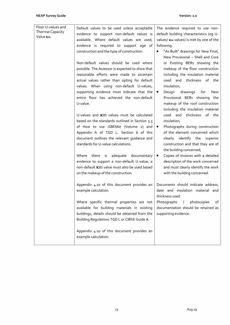
Floor U-values and Thermal Capacity
Value m
Default values to be used unless acceptable
evidence to support non-default values is
available. Where default values are used,
evidence is required to support age of
construction and the type of construction.
Non-default values should be used where
possible. The Assessor is expected to show that
reasonable efforts were made to ascertain
actual values rather than opting for default
values. When using non-default U-values,
supporting evidence must indicate that the
entire floor has achieved the non-default
U-value.
U-values and m values must be calculated
based on the standards outlined in Section 3.3
of How to use iSBEMie (Volume 2) and
Appendix A of TGD L. Section 6 of this
document outlines the relevant guidance and
standards for U-value calculations.
Where there is adequate documentary
evidence to support a non-default U-value, a
non-default m value must also be used based
on the makeup of the construction.
Appendix 4.10 of this document provides an
example calculation.
Where specific thermal properties are not
available for building materials in existing
buildings, details should be obtained from the
Building Regulations TGD L or CIBSE Guide A.
Appendix 4.10 of this document provides an
example calculation.
The evidence required to use non-
default building characteristics (eg U-
values/ m values) is met by one of the
following:
• “As Built” drawings for New Final,
New Provisional – Shell and Core
or Existing BERs showing the
makeup of the floor construction
including the insulation material
used and thickness of the
insulation;
• Design drawings for New
Provisional BERs showing the
makeup of the roof construction
including the insulation material
used and thickness of the
insulation;
• Photographs during construction
of the element concerned which
clearly identify the superior
construction and that they are of
the building concerned;
• Copies of invoices with a detailed
description of the work concerned
and must clearly identify the work
with the building concerned.
Documents should indicate address,
date and insulation material and
thickness used.
Photographs / photocopies of
documentation should be retained as
supporting evidence.

NEAP Survey Guide Version: 2.0
24 Aug 19
Door U-Value and Thermal Capacity
Value m
Default values to be used unless acceptable
evidence to support non-default values is
available. Where default values are used,
evidence is required to support age of
construction and the type of door installed.
Non-default values should be used where
possible. The Assessor is expected to show that
reasonable efforts were made to ascertain
actual values rather than opting for default
values.
U-values and m values must be calculated
based on the standards outlined in Section 3.3
of How to use iSBEMie (Volume 2) and
Appendix A of TGD L. Section 6 of this
document outlines the relevant guidance and
standards for U-value calculations.
Where there is adequate documentary
evidence to support a non-default U-value, a
default m value may be used if a non-default
value based on the makeup of the construction
is not available. The default m value should
be 6.75 kJ/m2K.
Where specific thermal properties are not
available for building materials in existing
buildings, details should be obtained from the
Building Regulations TGD L or CIBSE Guide A.
The evidence required to use non-
default building characteristics (eg, U-
values/ m values) are met by one of
the following:
• “As Built” drawings/ specification
for New Final, New Provisional –
Shell and Core or Existing BERs
detailing the Door make and
model and copies of certified U-
values;
• Design drawings/ specification for
New Provisional BERs detailing
the Door make and model and
copies of certified U values.
• Copies of invoices with technical
characteristics of the door, clearly
identifying that it relates to the
building concerned.
Documents should indicate building
address, date and details of the door in
question.
Photographs / photocopies of
documentation should be retained as
supporting evidence.

NEAP Survey Guide Version: 2.0
25 Aug 19
Window U-value, T-
Solar and L-Solar
Default values to be used unless acceptable
evidence to support non-default values for the
U-value, T Solar and L Solar is available. Non-
default values must be demonstrated for each
of the entries for U-value, T-Solar and L-Solar.
Otherwise, a default value should be used for
all. Where default values are used, evidence is
required to support age of construction and the
type of window installed.
Non-default values should be used where
possible. The Assessor is expected to show that
reasonable efforts were made to ascertain
actual values rather than opting for default
values.
Non-default values for U-values, Solar and
Light Transmittance values supplied by
manufacturers or suppliers are calculated based
on the standards outlined in Section 3.3 of How
to use iSBEMie (Volume 2 ) and Appendix A of
TGD L. The manufacturer/ supplier must
provide CE marked or Declaration of
Performance for the product with reference to
the relevant standards.
Film or signage applied to the glass to
advertise/ promote services or products is
regarded as occupier behaviour and should be
ignored for the purposes of the BER
assessment.
The evidence required to use non-
default building characteristics (eg, U-
values) are met by one of the
following:
• “As Built” drawings/ specification
for New Final, New Provisional –
Shell and Core or Existing BERs
detailing the window make and
model and copies of certified U-
values, solar and light values;
• Design drawings/ specification for
New Provisional BERs detailing
the window make and model and
copies of certified U-values, solar
and light values;
• Original installation
documentation from the installer
detailing window make and model
can be used if available (to obtain
certified data);
• Representative photographs of
the window, gap between glazing,
manufacturer’s stamp pointing to
certified data can be used as
supporting evidence. If measuring
the gap between glazing panes,
ensure that the thickness of the
glazing panes is not included in
the final glazing gap figure;
• Copies of invoices with technical
characteristics of the window and
must clearly identify the window
relates to the building concerned.

NEAP Survey Guide Version: 2.0
26 Aug 19
Curtain Walling Default values to be used unless acceptable
evidence to support non-default values for the
U-value of the curtain wall system, T Solar and
L Solar for the transparent element of the
curtain wall system is available. Non-default
values must be demonstrated for each of the
entries for U-value, T-Solar and L-Solar.
Non-default values for U-values, Solar and
Light Transmittance values supplied by
manufacturers or suppliers are calculated based
on the standards outlined in Section 3.3 of How
to use iSBEMie (Volume 2 ) and Appendix A of
TGD L. The manufacturer/ supplier must
provide CE marked or Declaration of
Performance for the transparent elements with
reference to the relevant standards.
A site-specific thermal transmittance
calculation should be undertaken by a
competent person e.g. façade engineer and
calculated in accordance with I.S. EN
12631:2012 taking on board the specific
geometry of the installed product/ system.
Thermal Bridging factors that are accounted for
in the curtain walling system should be set to
zero in the applicable zones in iSBEMie. These
would typically be lintel, sills, and jambs and
potentially wall - wall and wall – floor junctions.
For opaque sections of curtain walling or
spandrel panels the solar and light
transmittance values are set to zero.
The evidence required to use non-
default building characteristics (eg, U-
values) are met by one of the
following:
• “As Built” drawings/ specification
for New Final, New Provisional –
Shell and Core or Existing BERs
detailing the curtain walling make
and model and copies of certified
U-values, solar and light values;
• Design drawings/ specification for
New Provisional BERs detailing
the curtain walling make and
model and copies of certified U-
values, solar and light values;
• Original installation
documentation from the installer
detailing window make and model
can be used if available (to obtain
certified data);
• Representative photographs of
the window, gap between glazing,
manufacturer’s stamp pointing to
certified data can be used as
supporting evidence. If measuring
the gap between glazing panes,
ensure that the thickness of the
glazing panes is not included in
the final glazing gap figure;
Copies of invoices with technical
characteristics of the window and
must clearly identify the window
relates to the building concerned.
7.3 iSBEMie Software Tab: “Geometry > Project”
Data Entry Item Guidance Documentary Evidence
Building Infiltration For publication of a BER, use the air
permeability default value of 25 m3/h/m2 at 50
Pa unless a valid acceptable pressure test
certificate is available.
For large complex buildings with an envelope
area in excess of 160,000m2 such as airport
terminals, regional hospitals or large shopping
centres where it is not practical to implement a
Where a non-default value is used, a
copy of the pressure test certificate
must be provided with the following
details:
- address of the building
- date of the pressure test.
- Permeability (air leakage rate in
m3/hr divided by envelope area m2
at 50 Pascal pressure difference)

NEAP Survey Guide Version: 2.0
27 Aug 19
phased pressure testing approach, the
alternative approach outlined in Section 5.3 of
ATTMA document Technical Standard L2
Measuring Air Permeability of Building
Envelopes (Non-Dwellings) may be adopted.
Where this has been demonstrated a default of
5 m3/h/m2 at 50 Pa may be used.
The procedure for testing is specified in I.S. EN
ISO 9972: 2015 “Thermal performance of
buildings: determination of air permeability of
buildings: fan pressurization method”.
Detailed guidance on testing procedure is given
in ATTMA TSL2 publication “Measuring air
permeability of Building Envelopes” and
additional guidance is provided in CIBSE
Technical Manual TM 23 “Testing Buildings for
Air leakage”.
Pressure test certificates must be in
compliance with I.S. EN ISO 9972:
2015 “Thermal performance of
buildings: determination of air
permeability of buildings: fan
pressurization method” and CIBSE
Technical Manual TM23 “Testing
Buildings for Air Leakage”.
Individuals/ organisations carrying out
pressure tests must also demonstrate
that they are competent to carry out
the testing.
Individuals may, for example,
demonstrate competence to carry out
permeability tests on buildings by
being registered under the NSAI’s Air
Tightness Testers Scheme.
Additionally, individuals and
organisations may demonstrate
competence by being accredited to
carry out tests to I.S. EN ISO 9972:
2015 by the Irish National
Accreditation Board (INAB)
or any other bodies capable of providing accreditation to ISO /IEC 17025: “General Requirements for the Competence of Testing and Calibration Laboratories” For Provisional BER certificates the assessor must have evidence of one of the following: - that the Developer/ Builder has history of achieving proposed air leakage for similar type/ size buildings. - has appointed Air Tightness consultant for design and construction observation. The air tightness consultant must have previous experience of delivering similar air tightness levels. The air tightness consultant may be a member of the design team.
Building orientation The default is set at zero, and should only be
changed with caution. Refer to Section 3.4.2 of
How to use iSBEMie (Volume 2).
Copy of site plan of building with
orientation or a photograph of
compass in relation to the building.
Zone Height (Global) Enter the floor to floor or floor to soffit for top Building sketches with dimensions,

NEAP Survey Guide Version: 2.0
28 Aug 19
floor. Refer to Appendix 6 of this document.
This will then be the default zone height
applied to all zones and can be edited at zone
level
calculations and Survey Form
or
Architectural drawings with
dimensions, calculations and Survey
Form.
Building sketches/ architectural
drawings should show the depth of all
components, including floor slabs,
floor voids, ceiling voids etc.
Maximum number of
storeys
Enter the maximum number of storeys in the
building
Building sketches with dimensions,
calculations and Survey Form
or
Architectural drawings with
dimensions, calculations and Survey
Form.
Building area Enter the total floor area of building.
Refer to Section 3.4 Measurement and Other
Conventions in How to use iSBEMie (Volume 1)
and Section 3.4.3 of How to use iSBEMie
(Volume 2).
Floor by floor sketches with
dimensions and calculations
or
Architectural drawings with
dimensions and calculations marked
up to show zones.
Global Thermal
bridges
For existing buildings, it is unlikely that
sufficient evidence will be obtainable to
substantiate the use of non-default thermal
bridging values.
Where insufficient evidence is available the
input fields must be left blank, resulting in
default figures being used.
As outlined in Section 3.4.2 of How to use
iSBEMie (Volume 2), the values visible are
further degraded in the calculation process.
The values used in the calculation can be
accessed from the data reflection report. Refer
to Section 4.2.3 of How to use iSBEMie
(Volume 2) for details on how to access the
report.
Non-default thermal bridging values should be
used where possible for new buildings. The
Assessor is expected to show that reasonable
efforts were made to ascertain actual values
rather than opting for default values.
Where a non-default value is used,
acceptable documentary evidence
must be provided for the building.
Where accredited data is available one
of the following must be provided:
- For psi values from “Limiting Thermal
Bridging and Air
Infiltration - Acceptable Construction
Details’’ (http://www.environ.ie) as
referenced in Appendix D of the
Building Regulations TGD L,
documentary evidence must be
provided that demonstrates that the
details have been conformed to. This
requires that:
1) the relevant drawings clearly
show the relevant details and
that these details are checked
and signed off by the
developer/builder, site
engineer or architect.
2) As built Plans/ Sections/
Elevation drawings showing

NEAP Survey Guide Version: 2.0
29 Aug 19
all key junction locations and
reference to detailed drawing
for New Final, New
Provisional – Shell and Core
and Existing BERs.
3) Design Plans/ Sections/
Elevation drawings showing
all key junction locations and
reference to detailed drawing
for New Provisional BERs.
- Certified psi values are used,
documentary evidence in accordance
with the methods described in IS EN
ISO 10211:2017 and BR 497: 2016 must
be provided.
These calculations of two dimensional
or three-dimensional heat flow require
the use of numerical modeling
software. To be acceptable, numerical
modeling software should model the
validation examples in IS EN ISO
10211:2017 with results that agree with
the stated values of temperature and
heat flow within the tolerance
indicated in the standard for these
examples.
Detailed guidance on decisions
regarding specific input to the
modeling software and the
determination of certain quantities
from the output of the software is
contained in BRE Report BR 497
Conventions for calculating linear
thermal transmittance and
temperature factors. This guidance
should be followed in carrying out
modeling work so that different users
of the same software package and
users of different software packages
can obtain correct and consistent
results.
Certification of the detail by a member
of the NSAI Thermal Modellers’
Certification Scheme, certified by a
third body such as Agrement or
equivalent or from accredited
database such as the BRE Certified

NEAP Survey Guide Version: 2.0
30 Aug 19
Thermal Details and Products Scheme
is a means of meeting the
requirements in TGD L and NEAP for
calculation of Ψ values.
7.4 iSBEMie Software Tab: “Geometry > Zones > General”
Data Entry Item Guidance Documentary Evidence
HVAC System The use of default HVAC systems is detailed in
Appendix 4.3 and Appendix 7 of this document.
The appendices deal specifically with the
following circumstances:
- Shell and Core Buildings
- No HVAC present in the building/ zone
For further detail on default HVAC systems
refer to Section 3.4.3 of How to use iSBEMie
(Volume 2).
The BER is based on non-default HVAC systems
where there is sufficient evidence available. As
outlined in Section 6 of this document the
Assessor is expected to show that reasonable
efforts were made to ascertain non-default
values rather than opting for default values.
The evidence required in order to use
non-default building characteristics is
met by one of the following in
conjunction with the plantroom survey
and ceiling void details:
• Copy of as built HVAC drawings
and specifications for New Final
and Existing BERs;
• Copy of design HVAC drawings
and specifications for New
Provisional BERs;
• Copy of technical details from
operational and maintenance
manuals;
• Representative photographs of
the HVAC system.
Building Type/ Activity The activity specified sets default parameters
which the tool uses to calculate the energy
consumption. These parameters include
temperature set points, heat gains from people
and equipment, required illuminance, and fresh
air requirements amongst others.
For details Refer to Section 3.4.3 of How to use
iSBEMie (Volume 2).
In combination with the floor by floor
sketches /architectural drawings
marked up to show zones the
following should be provided:
• Survey Form;
• Note on basis used to define
zones.
Area Floor area of zone.
Refer to Section 3.4 Measurement and Other
Conventions in How to use iSBEMie (Volume 1)
and Section 3.4.3 of How to use iSBEMie
(Volume 2).
Floor by floor sketches with
dimensions and calculations
or
Architectural drawings with
dimensions and calculations marked
up to show zones.
Height Height of zone
Refer to Section 3.4 Measurement and Other
Conventions in How to use iSBEMie (Volume 1)
and Section 3.4.3 of How to use iSBEMie
(Volume 2).
Building sketches with dimensions,
calculations and Survey Form
or
Architectural drawings with
dimensions, calculations and Survey

NEAP Survey Guide Version: 2.0
31 Aug 19
Refer to Appendix 6 of this document for
examples of zone height calculation.
Form.
Building sketches/ architectural
drawings should show the depth of all
components, including floor slabs,
floor voids, ceiling voids etc.
Zone Infiltration Guidance as per “Building Infiltration” Documentary Evidence as per
“Building Infiltration”
Thermal Bridges Guidance as per “Global Thermal Bridges”
Thermal Bridging factors that are accounted for
in the curtain walling system should be set to
zero in the applicable zones in iSBEMie.
Documentary Evidence as per “Global
Thermal Bridges”
7.5 iSBEMie Software Tab: “Geometry > Envelope”
Data Entry Item Guidance Documentary Evidence
Name Refer to Section 3.5 Nomenclature in How to
use iSBEMie (Volume 1). for guidance.
Not applicable.
Zone Zone that envelope element is part of. Floor by floor sketches with
dimensions and Survey Form
or
Architectural drawings with
dimensions and marked up to show
zones and Survey Form.
Type of Envelope Choose between wall, floor/ceiling and roof. Not applicable.
Construction Choose from Constructions set up in Project
Database for envelope type.
Floor by floor sketches with
dimensions and Survey Form and
photographs
or
Architectural drawings with
dimensions and marked up to show
zones and Survey Form and
photographs.
Connects Space to Choose what conditions apply to the other side
of the wall, floor/ceiling or roof.
Refer to Section 3.4.4 of How to use iSBEMie
(Volume 2) for definitions.
Refer to Appendix 8 of this document for
further guidance.
Floor by floor sketches with
dimensions and Survey Form
or
Architectural drawings with
dimensions and marked up to show
zones and Survey Form.
Orientation This Specifies the orientation of the envelope
element. Select from one of the available
options.
Copy of site plan or sketch of building
with orientation and photograph of
compass in relation to the building.
Area Area of envelope inclusive of any windows/
doors.
Refer to Section 3.4 Measurement and Other
Floor by floor sketches with
dimensions, calculations and Survey
Form or Architectural drawings with

NEAP Survey Guide Version: 2.0
32 Aug 19
Conventions in How to use iSBEMie (Volume 1)
for guidance.
dimensions, calculations and marked
up to show zones and Survey Form.
Perimeter Enter the horizontal dimension of the wall, as
per Section 3.4 Measurement and Other
Conventions in How to use iSBEMie (Volume 1)
This field becomes active for wall elements
only.
The default value is based on area of the
element divided by the entered zone height.
For some wall elements e.g. a gable end wall
this calculated value will not be correct and will
need to be overridden manually.
Floor by floor sketches with
dimensions, calculations and Survey
Form
or
Architectural drawings with
dimensions, calculations and marked
up to show zones and Survey Form.
Pitch Enter pitch angle, in degrees from the
horizontal.
This field becomes active for “roof” or “floor or
ceiling” elements only.
The default value for roof is 45o and for floor or
ceiling is 0o.
Floor by floor sketches with
dimensions, calculations and Survey
Form
or
Architectural drawings with
dimensions, calculations and marked
up to show zones and Survey Form.
Tick if there is a solar
collector on this wall
Tick if there is a solar collector present.
This field becomes active for “wall” elements
only and where a Solar Collector has been
defined.
Guidance as per “Solar Collectors”
Additional Thermal
Bridges
Enter additional thermal bridges to those
already described in the Thermal Bridges
Project or Zone tab.
Guidance as per “Global Thermal Bridges”
Documentary Evidence as per “Global
Thermal Bridges”
7.6 iSBEMie Software Tab: “Geometry > Doors”
Data Entry Item Guidance Documentary Evidence
Name Refer to Section 3.5 Nomenclature in How to
use iSBEMie (Volume 1) for guidance.
Not applicable.
In Envelope Enter the Envelope that Door is part of.
Note: Doors located in internal walls are not
entered. The entire wall area is entered as if
there were no door.
Note: Doors with more than 50% glazed should
be entered as a window.
Refer to Section 3.3 in How to use iSBEMie
(Volume 2).
Floor by floor sketches with
dimensions and Survey Form
or
Architectural drawings with
dimensions and marked up to show
zones and Survey Form.
Type Choose between High Usage Entrance, Not applicable.

NEAP Survey Guide Version: 2.0
33 Aug 19
Personnel, and Vehicle Access Doors.
Construction Choose from Constructions set up in Project
Database for door type.
Floor by floor sketches with doors
identified and Survey Form and
photographs
or
Architectural drawings with doors
identified and marked up to show
zones and Survey Form and
photographs.
Area Enter the Area of structural opening in wall
including frame.
Refer to Section 3.4 Measurement and Other
Conventions in How to use iSBEMie (Volume 1).
Building sketches with dimensions and
Survey Form
or
Architectural drawings with
dimensions and Survey Form.
7.7 iSBEMie Software Tab: “Geometry > Windows and Rooflights”
Data Entry Item Guidance Documentary Evidence
Name Refer to Section 3.5 Nomenclature in How to
use iSBEMie (Volume 1) for guidance.
Not applicable.
In Envelope Enter the Envelope that window/rooflight is
part of.
Floor by floor sketches with
dimensions and Survey Form
or
Architectural drawings with
dimensions and marked up to show
zones and Survey Form.
Glazing Type Choose between the glazing types defined in
Project Database or default glazing.
Floor by floor sketches with glazing
type identified and Survey Form and
photographs
or
Architectural drawings with glazing
type identified and marked up to show
zones and Survey Form and
photographs.
Area Enter the Area of structural opening in wall/roof
including frame.
Refer to Section 3.4 Measurement and Other
Conventions in How to use iSBEMie (Volume 1)
for measurement conventions.
Building sketches with dimensions and
Survey Form
or
Architectural drawings with
dimensions and Survey Form.
Surface Area Ratio Enter the ratio of the “developed area to
projected area” for the window or rooflight as
defined in Section 3.4.5 of How to use iSBEMie
(Volume 2).
The developed area is the total area of the glass
plus frame. The projected area is the area of
the opening in the envelope.
Building sketches with dimensions and
Survey Form
or
Architectural drawings with
dimensions and Survey Form.

NEAP Survey Guide Version: 2.0
34 Aug 19
Display Window
Tickbox
Tick if the window is a “Display Window”. This is a window intended for the display of products or services on offer within the building, positioned:
• At external perimeter of the building; and
• At an access level and immediately adjacent to a pedestrian thoroughfare.
Glazing more than 4m above such an access level or incorporates a fixed or opening light of less than 2m2, should not be considered part of the display window except:
• Where the size of individual products on display require a greater height of glazing;
• where changes to the façade requiring planning (including glazing) require a greater height of glazing, e.g. to fit in with surrounding buildings or to match the character of the existing façade.
Building sketches with dimensions and
Survey Form
or
Architectural drawings with
dimensions and Survey Form.
Area Ratio Covered Enter the ratio of the roof area covered by an
array of rooflights to the total area of the
rooflight glazing.
Refer to Section 3.4.5 of How to use iSBEMie
(Volume 2) for definition.
Building sketches with dimensions and
Survey Form
or
Architectural drawings with
dimensions and Survey Form.
Frame Factor Enter the ratio of the window or rooflight area which is occupied by the frame to the total window or rooflight area. The default value is 0.1 for a window (i.e., 10% of the total area is occupied by the frame and 90% by the glazing) and 0.3 for a rooflight. Note: This will impact on solar gain.
Refer to Section 3.4.5 of How to use iSBEMie
(Volume 2) for definition.
Building sketches with dimensions and
Survey Form
or
Architectural drawings with
dimensions and Survey Form
or
Window manufacturers technical data
sheets and declarations for installed
window system in specific building
Aspect Ratio Enter the ratio of a windows height to the
windows width. (i.e. window height / window
width)
Note: This will impact on the thermal bridging
calculations for the Lintel, Sill and Jamb
lengths.
The default value is 0.7.
Refer to Section 3.4.5 of How to use iSBEMie
(Volume 2) for definition.
Building sketches with dimensions and
Survey Form
or
Architectural drawings with
dimensions and Survey Form
or
Window manufacturers technical data
sheets and declarations for installed
window system in specific building
Shading position Choose from None (no shading), Internal or
External based on the presence of movable
Building sketches or Survey Form and
photographs

NEAP Survey Guide Version: 2.0
35 Aug 19
solar shading device.
Refer to Section 3.4.5 of How to use iSBEMie
(Volume 2) for definition.
or
Architectural drawings and Survey
Form and photographs.
Shading colour Choose the colour of the movable solar shading
device from Black, Dark, Pastel or White.
Refer to Section 3.4.5 of How to use iSBEMie
Compliance Assessment for definition.
Building sketches or Survey Form and
photographs
or
Architectural drawings and Survey
Form and photographs.
or
Solar Shading manufacturers technical
data sheets and declarations for
installed system in specific building
Shading translucency Choose the translucency of the movable solar
shading device from High translucent, Medium
translucent or Opaque.
Opaque = 0% transmittance
Medium Translucent = 20% transmittance
High Translucent = 40% transmittance
Refer to Section 3.4.5 of How to use iSBEMie
(Volume 2) for definition.
Building sketches or Survey Form and
photographs
or
Architectural drawings and Survey
Form and photographs.
or
Solar Shading manufacturers technical
data sheets and declarations for
installed system in specific building
Transmission Factor This is the fraction of light transmitted through
that specific window after accounting for
shading from overhangs and fins.
For details on how to calculate the transmission
factor, see Section 3.4.6: Transmission
Correction Factors of How to use iSBEMie
(Volume 2).
Building sketches with dimensions and
Survey Form and photographs
or
Architectural drawings with
dimensions and Survey Form and
photographs.
Brise-Soleil Tickbox Tick this box if the overhang whose
transmission factor is accounted for in the
previous parameter is in fact a brise-soleil.
Brise-Soleil for iSBEMie can be strips, louvres,
holes etc as opposed to solid overhang.
Refer to Section 3.4.5 of How to use How to use
iSBEMie (Volume 2) for definition.
Building sketches with dimensions and
Survey Form and photographs
or
Architectural drawings with
dimensions and Survey Form and
photographs
or
Solar Shading manufacturers technical
data sheets and declarations for
installed system in specific building
7.8 iSBEMie Software Tab: “Building Services > Global and Defaults > HVAC System Defaults”
Data Entry Item Guidance Documentary Evidence
HVAC System Defaults Refer to Appendix A4.2 of this document for
details on default HVAC system entry.
The basis for selecting a default system
must be documented and retained

NEAP Survey Guide Version: 2.0
36 Aug 19
Default systems are only used where actual
systems do not exist or are too incomplete. (See
Section 4.8 of this document for guidance on
non-operational and missing equipment.)
Where actual systems exist, they are defined as
per iSBEMie Software Tab: “Building Services
> HVAC Systems > General” as described later
in this document.
This sub-tab is not available for a Part L only
assessment.
together with supporting information.
Building sketches with dimensions and
Survey Form and photographs
Photographs of areas where default
systems are to be allocated
As Built drawings and specifications for
New Final and Existing BERs.
Design drawings and specifications for
Existing BERs.
7.9 iSBEMie Software Tab: “Building Services > Global and Defaults > Project Building Services”
Data Entry Item Guidance Documentary Evidence
Is the lighting
separately
metered?
Answering “yes” to this input would require the Assessor
to obtain formal confirmation that the lighting is
separately metered.
The evidence required in order to
answer “Yes” is met by one of the
following
• Copy of As Built electrical
schematics showing meters for
New Final and Existing BERs;
• Copy of Design electrical
schematics showing meters for
New Provisional BERs
• Photograph of sub-meter
permanently labelled showing it
is for lighting
• Letter from an electrical
contractor advising that they
have checked the system in the
last 12 months and confirming
that it is separately metered.
M&T with alarm
for “out of range”
values?
The Assessor must ascertain if such a system is installed,
M&T system must have alarm for “Out of Range” values.
For New Final or Existing BERs, the
evidence required is details of M&T
system from operational and
maintenance manuals. Review the
BMS to ensure that the system is in
operation or review records for
previous 12 months.
For New Provisional BERs
specification of the BMS/ BEMS
should be provided demonstrating

NEAP Survey Guide Version: 2.0
37 Aug 19
function.
Electricity Power
Factor
The default power factor value of <0.9 must be used in an
existing building unless analysis of the recent 12 month’s
bill data indicates a different value.
The default power factor value of <0.9 must be used in a
new building unless one of the following is demonstrated:
1) A power factor of >0.95 can be used in a new building
where there is adequate documentary evidence to support the installation of power factor correction equipment within the building for final certificates and the proposed installation of power factor correction equipment for provisional certificates.
2) A non-default power factor can be used for a Final BER in a new building where a suitably qualified electrical engineer has produced a report detailing the expected power factor for the building as constructed.
3) A non-default power factor can be used for a
Provisional BER in a new building where a suitably qualified electrical engineer has produced a report detailing the expected power factor for the building as per the design.
Electricity utility bills for 12-month
period prior to assessment of an
existing building.
For a new building, detail of installed
power factor correction equipment
or a signed report from a suitably
qualified electrical engineer.
Has LENI
calculation been
carried out?
Answering “yes” to this input confirms that a Lighting
Numerical Indicator (LENI) method has been carried out
for the building as an alternative to complying with the
lighting efficacy standards specified in Part L. This will be
reported in the BRIRL output document.
Note: The lighting energy calculation in iSBEMie is not
affected by this data entry item.
The evidence required in order to
answer “Yes” is met by a signed
statement from a suitably qualified
engineer from the consultants
responsible for the lighting design
showing:
• LENI Calculations in compliance
with Appendix F of Part L of the
Building Regulations.
• As Built Specification and
Drawings for New Final BER
• Design Specification and
Drawings for New Provisional
BER
.
Process Energy
for RER: Primary
Energy Exported
This field allows entry of a figure for total process primary
energy exported annually contributing to the Renewable
Energy Ratio for Part L compliance.
Note: It does not impact on the energy and carbon
performance compliance requirements or the Building
For new buildings, a report from a
suitably qualified member of the
design team, detailing how the
renewable primary energy exported
has been calculated.

NEAP Survey Guide Version: 2.0
38 Aug 19
Energy Rating.
The process energy should not be accounted for in the
regulated loads included in the NEAP methodology.
The report should be submitted for
review to SEAI/ DHPLG prior to
inclusion in the NEAP methodology.
Process Energy
for RER: Primary
Energy used
This field allows entry of a figure for total process primary
energy exported annually contributing to the Renewable
Energy Ratio for Part L compliance.
Note: It does not impact on the energy and carbon
performance compliance requirements or the Building
Energy Rating.
The process energy should not be accounted for in the
regulated loads included in the NEAP methodology.
For new buildings, a report from a
suitably qualified member of the
design team, detailing how the
renewable primary energy used has
been calculated.
The report should be submitted for
review to SEAI/ DHPLG prior to
inclusion in the NEAP methodology.
District Heating
Parameters
District Heating is defined as a central system serving
multiple buildings from a system outside the boundaries
of the site.
The default value must be used if District Heating is
selected as the heat source and there is no documentary
evidence to substantiate non-default entries.
A non-default value is used where possible. The Assessor
should ascertain the CO2 emission factor and primary
energy factor for district heating which should reflect the
average annual efficiency and fuel mix of the whole
district heating system. It should include for all the gross
efficiencies of heat generating plants, including any CHP
generators, any waste heat recovery or heat dumping, the
effect of heat losses in distribution (external to the
building), the emissions from electricity used for pumping,
and any other relevant carbon dioxide emissions.
For existing buildings, a report from
the district heating scheme
operator, detailing how the CO2
emission and primary energy factors
for the district heating have been
derived.
For new buildings, a report from a
suitably qualified member of the
design team, detailing how the CO2
emission and primary energy factors
for the district heating have been
derived.
The calculations should be based on
actual fuel bills over a 1-year period.
Where a renewable primary energy
conversion factor is proposed, the
report should be submitted to SEAI/
DHPLG prior to inclusion in the
NEAP methodology.
The CO2 emission factors and
primary energy factors for the fuel(s)
used by the district heating system
should be taken from Appendix 12 of
this document.

NEAP Survey Guide Version: 2.0
39 Aug 19
7.10 iSBEMie Software Tab: “Building Services > HVAC Systems > General”
Data Entry Item Guidance Documentary Evidence
Type Select from the Building Services Type options in
Database for Building Services. Follow guidance
in Section 3.5.2 of How to use iSBEMie (Volume
2).
Categorising the HVAC system is an important
aspect of BER production because such systems
account for the major proportion of energy used
in a building.
The Assessor must be familiar with the various
types of HVAC systems as categorised in Table 7
of How to use iSBEMie (Volume 2).
The Assessor must be capable of categorising
the system based on the limited information
available on site.
For New Final and Existing BERs, in
conjunction with the plantroom survey
details and ceiling void details the
evidence required is met by one of the
following:
• Photographs of air handling units,
ducting, associated equipment in
ceiling voids, heater/cooling
batteries, fresh air intakes,
discharge grilles, actuated
dampers, etc;
• Copies of technical data sheets
from operational and maintenance
manuals;
• As Built drawings and
specifications.
For New Provisional BERs, design
drawings, specifications and technical
data sheets must be provided.
The basis for categorising a system
must be documented and retained
together with supporting information.
Heat Source Select from the Heating Sources options in the
database
For New Final and Existing BERs, in
conjunction with the plantroom survey
details, the evidence required is met by
one of the following:
• Photographs of heat source plant
(eg boiler nameplates and
manufacturer name);
• Copies of technical data sheets
from operational and maintenance
manuals;
• As Built drawings and
specifications.
For New Provisional BERs, design
drawings, specifications and technical
data sheets must be provided.
Fuel Type Select from the Fuel Types
For New Final and Existing BERs, in
conjunction with the plantroom survey

NEAP Survey Guide Version: 2.0
40 Aug 19
For further guidance on the selection of solid fuel
types refer to Appendix 10 of this document.
details, the evidence required is met by
one of the following:
• Photographs of heat source plant
(eg boiler nameplates and
manufacturer name);
• Copies of technical data sheets
from operational and maintenance
manuals;
• As built drawings and
specifications.
For New Provisional BERs, design
drawings, specifications and technical
data sheets must be provided.
Tick if this system also
uses CHP
The Assessor must ascertain if the heating
system derives its heat, or part of it, from a
combined heat and power system. When this is
ticked in iSBEMie, a new tab opens, “CHP
generator”.
For New Final and Existing BERs, in
conjunction with the plantroom survey
details, the evidence required is met by
one of the following:
• Photographs of CHP plant with
nameplates and manufacturer
name;
• Copies of technical data sheets
from operational and maintenance
manuals;
• As built drawings and
specifications.
For New Provisional BERs, design
drawings, specifications and technical
data sheets must be provided.
Cooling System
Generator Type
Select from the Generator Types options in the
database.
For New Final and Existing BERs, in
conjunction with the plantroom survey
details, the evidence required is met by
one of the following:
• Photographs of cooling plant (eg
chiller nameplates and
manufacturer name);
• Copies of technical data sheets
from operational and maintenance
manuals;
• As built drawings and
specifications.
For New Provisional BERs, design

NEAP Survey Guide Version: 2.0
41 Aug 19
drawings, specifications and technical
data sheets must be provided.
Ventilation - Heat
Recovery
The heat recovery system may be incorporated
within the air handling unit(s) or it may be
external.
The Assessor must establish whether or not heat
recovery is fitted
For New Final and Existing BERs, in
conjunction with the plantroom survey
details, the evidence required is met by
one of the following:
• Photographs of heat recovery unit;
• Copies of technical data sheets
from operational and maintenance
manuals
• As Built drawings and
specifications.
For New Provisional BERs, design
drawings and specifications.
Tick if variable heat
recovery efficiency
Tick box if documentary evidence is available to
show that the heat recovery system can be
bypassed or switched off in summer.
For New Final and Existing BERs, in
conjunction with the plantroom survey
details, the evidence required is met by
one of the following:
• Photographs of bypass/ controls;
• Copies of technical data sheets
from operational and maintenance
manuals
• As Built drawings and
specifications.
For New Provisional BERs, design
drawings and specifications.
Heat Recovery
Seasonal Efficiency
The default value must be used for efficiency if
there is no documentary evidence to
substantiate non-default entries.
A non-default value should be used where
possible. Non-default efficiency values must be
in compliance with the Commission Regulation
(EU) 1253/2014 with regard to ecodesign
requirements for ventilation units.
Non-default efficiencies may be obtained from
the following sources as per Section 6.1:
• Performance data on “CE marked”
literature is acceptable provided that the
For New Final and Existing BERs, in
conjunction with the plantroom survey
details, the evidence required is met by
one of the following:
• Photographs of heat recovery unit;
• Copies of technical data sheets
from operational and maintenance
manuals
• Sources of efficiency as outlined in
“Guidance” and Section 6.1;
• As Built drawings and
specifications.
For New Provisional BERs, design

NEAP Survey Guide Version: 2.0
42 Aug 19
literature refers to the relevant test performance standard.
• Literature from manufacturer referencing the efficiency and relevant Ecodesign standard.
• Accredited Test certificates to the relevant test performance standard
drawings, specifications and sources of
efficiency as outlined in “Guidance” and
Section 6.1.
7.11 iSBEMie Software Tab: “Building Services > HVAC Systems > Heating”
Data Entry Item Guidance Documentary Evidence
Does it qualify for
ECA/ACA?
Check the equipment concerned at
http://www.SEAI.ie/Your_Business/Accelerated_
Capital_Allowance
Or the UK equivalent
https://etl.beis.gov.uk/engetl/fox/live/ETL_PUBL
IC_PRODUCT_SEARCH
Take note of the specific equipment
make and model number and show
corresponding details on ACA webpage
(or ECA now called ETL, the UK
equivalent). Include a snapshot of the
relevant page from the website. A web
link to the page is not acceptable since
it may expire.
ETL allows the user to receive an
automated email with the product
listing. ACA can generate an Excel file
with the product listing. Both of these
are acceptable as supporting evidence
for this entry.
Do you know the
effective heat
generating seasonal
efficiency?
It is important to note that there is a difference
between the “as tested” efficiency of a boiler,
the “gross seasonal” efficiency and the “Effective
Heat Generating Seasonal Efficiency” as
required in iSBEMie.
Refer to Appendix 5 of this document for further
guidance on the effective heat generating
seasonal efficiency to be used.
Non-default efficiencies may be obtained from
the following sources as per Section 6.1 of this
document:
• Performance data on “CE marked”
literature is acceptable provided that the literature refers to the relevant test performance standard.
In conjunction with the plantroom
survey details, the evidence required is
met by one of the following:
• Photographs of heat source plant
(eg boiler nameplates and
manufacturer name) and
manufacturer’s data sheets;
• Sources of efficiency as outlined in
Section 6.1 of this document;
• Copies of technical data sheets
from operational and maintenance
manuals;
• As Built drawings and specifications
for New Final or Existing BERs;
• Design drawings and specifications
for New Provisional BERs;
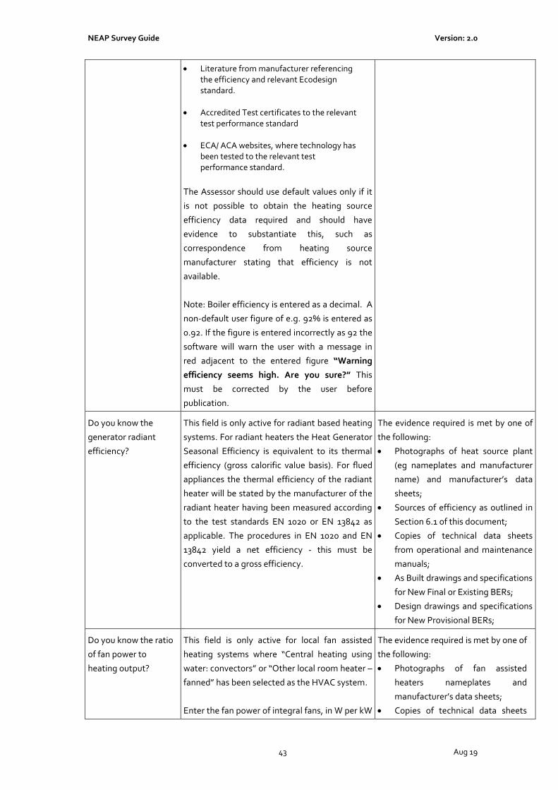
NEAP Survey Guide Version: 2.0
43 Aug 19
• Literature from manufacturer referencing the efficiency and relevant Ecodesign standard.
• Accredited Test certificates to the relevant test performance standard
• ECA/ ACA websites, where technology has been tested to the relevant test performance standard.
The Assessor should use default values only if it
is not possible to obtain the heating source
efficiency data required and should have
evidence to substantiate this, such as
correspondence from heating source
manufacturer stating that efficiency is not
available.
Note: Boiler efficiency is entered as a decimal. A
non-default user figure of e.g. 92% is entered as
0.92. If the figure is entered incorrectly as 92 the
software will warn the user with a message in
red adjacent to the entered figure “Warning
efficiency seems high. Are you sure?” This
must be corrected by the user before
publication.
Do you know the
generator radiant
efficiency?
This field is only active for radiant based heating
systems. For radiant heaters the Heat Generator
Seasonal Efficiency is equivalent to its thermal
efficiency (gross calorific value basis). For flued
appliances the thermal efficiency of the radiant
heater will be stated by the manufacturer of the
radiant heater having been measured according
to the test standards EN 1020 or EN 13842 as
applicable. The procedures in EN 1020 and EN
13842 yield a net efficiency - this must be
converted to a gross efficiency.
The evidence required is met by one of
the following:
• Photographs of heat source plant
(eg nameplates and manufacturer
name) and manufacturer’s data
sheets;
• Sources of efficiency as outlined in
Section 6.1 of this document;
• Copies of technical data sheets
from operational and maintenance
manuals;
• As Built drawings and specifications
for New Final or Existing BERs;
• Design drawings and specifications
for New Provisional BERs;
Do you know the ratio
of fan power to
heating output?
This field is only active for local fan assisted
heating systems where “Central heating using
water: convectors” or “Other local room heater –
fanned” has been selected as the HVAC system.
Enter the fan power of integral fans, in W per kW
The evidence required is met by one of
the following:
• Photographs of fan assisted
heaters nameplates and
manufacturer’s data sheets;
• Copies of technical data sheets

NEAP Survey Guide Version: 2.0
44 Aug 19
heat output by the heating system. from operational and
maintenance manuals;
• As Built drawings and specifications
for New Final or Existing BERs;
• Design drawings and specifications
for New Provisional BERs.
Tick if this system also
uses CHP
Refer to previous section “Building Services >
HVAC Systems > General”
Refer to previous section “Building
Services > HVAC Systems > General”
7.12 iSBEMie Software Tab: “Building Services > HVAC Systems > Cooling”
Data Entry Item Guidance Documentary Evidence
Generator kW Select the cooling generator nominal electrical
power.
In conjunction with the plantroom
survey details, the evidence required is
met by one of the following:
• Photographs of cooling plant (eg
chiller nameplates and
manufacturer name) and
manufacturer’s data sheet;
• Copies of technical data sheets
from operational and maintenance
manuals;
• As Built drawings and specifications
for New Final or Existing BERs;
• Design drawings and
specifications for New Provisional
BERs.
Fuel Type Select from the Fuel Types
In conjunction with the plantroom
survey details, the evidence required is
met by one of the following:
• Photographs of cooling plant (eg
chiller nameplates and
manufacturer name) and
manufacturer’s data sheet;
• Copies of technical data sheets
from operational and maintenance
manuals;
• As Built drawings and specifications
for New Final or Existing BERs;
• Design drawings and specifications
for New Provisional BERs.

NEAP Survey Guide Version: 2.0
45 Aug 19
Does it qualify for ACA
or ECA?
Check the equipment concerned at
http://www.SEAI.ie/Your_Business/Accelerated_
Capital_Allowance
Or the UK equivalent
https://etl.beis.gov.uk/engetl/fox/live/ETL_PUBL
IC_PRODUCT_SEARCH .
Take note of the equipment and details
on ACA/ECA webpage as outlined
above.
Do you know the
generator seasonal
energy efficiency ratio
(SEER)?
Refer to Appendix 5 of this document for further
guidance on the effective heat generating
seasonal efficiency to be used.
Non-default efficiencies may be obtained from
the following sources:
• Performance data on “CE marked”
literature is acceptable provided that the literature refers to the relevant test performance standard.
• Literature from manufacturer referencing the efficiency and relevant Ecodesign standard.
• Accredited Test certificates to the relevant test performance standard.
• ECA/ ACA websites, where technology has been tested to the relevant test performance standard.
• Eurovent website, where technology has been tested to the relevant test performance standard.
The Assessor should use default values only if it
is not possible to obtain the cooling plant
efficiency data required and should have
evidence to substantiate this, such as
correspondence from chiller manufacturer
stating that efficiency is not available.
In conjunction with the plantroom
survey details, the evidence required is
met by one of the following:
• Photographs of cooling plant (eg
chiller nameplates and
manufacturer name) and
manufacturer’s data sheet;
• Sources of efficiency as outlined in
Section 6.1 of this document;
• Copies of technical data sheets
from operational and maintenance
manuals;
• As Built drawings and specifications
for New Final or Existing BERs;
• Design drawings and
specifications for New Provisional
BERs.
Do you know the
generator nominal
energy efficiency ratio
(EER)?
Please note that in this guide the term “Energy
Efficiency Ratio (EER)” has the same meaning
as the “Nominal Energy Efficiency Ratio (EER)”
used in iSBEMie.
Non-default efficiencies may be obtained from
the following sources:
• Performance data on “CE marked”
literature is acceptable provided that the
In conjunction with the plantroom
survey details, the evidence required is
met by one of the following:
• Photographs of cooling plant (eg
chiller nameplates and
manufacturer name) and
manufacturer’s data sheet;
• Sources of efficiency as outlined in
“Section 6.1 of this document;

NEAP Survey Guide Version: 2.0
46 Aug 19
literature refers to the relevant test performance standard.
• Literature from manufacturer referencing the efficiency and relevant Ecodesign standard.
• Accredited Test certificates to the relevant test performance standard.
• ECA/ ACA websites, where technology has been tested to the relevant test performance standard.
• Eurovent website, where technology has been tested to the relevant test performance standard.
The Assessor should use default values only if it
is not possible to obtain the cooling plant
efficiency data required and should have
evidence to substantiate this, such as
correspondence from chiller manufacturer
stating that efficiency is not available.
• Copies of technical data sheets
from operational and maintenance
manuals;
• As Built drawings and specifications
for New Final or Existing BERs;
• Design drawings and
specifications for New Provisional
BERs.
Tick box to indicate if
the HVAC system uses
a mixed mode cooling
operation
To tick the box the assessor must have
documentary evidence to support:
• Natural ventilation from operable windows
is present
• Mechanical cooling is present.
In conjunction with the survey details,
the evidence required is met by one of
the following:
• Photographs of cooling plant and
openable windows within the
building.
• As Built drawings and specifications
for New Final or Existing BERs;
• Design drawings and
specifications for New Provisional
BERs.
7.13 iSBEMie Software Tab: “Building Services > HVAC Systems > System Adjustment”
Data Entry Item Guidance Documentary Evidence
Has the ductwork been
leakage tested?
Non-default classification leakage may be
obtained from the following sources:
• Test data in compliance with B&ES DW/143
and B&ES DW/144 identifying the Class of leakage.
• Specifications in compliance with EN standards such as IS EN 1507:2006, IS EN 12237:2003 and IS EN 13403:2003.
The evidence required is met by one of
the following:
• Copy of Test Certificates from
test on site, test must be carried
out to CEN standards for New
Final or Existing BERs;
• Design drawings and
specifications for New Provisional
BERs.

NEAP Survey Guide Version: 2.0
47 Aug 19
Does the AHU meet
CEN leakage
standards?
Non-default classification leakage may be
obtained from the following sources:
• Test data in compliance IS EN 1886:2007.
• Specifications in compliance with EN standards such as IS EN 1886:2007
The evidence required is met by one of
the following:
• Copy of Test Certificates, test
must be carried out to CEN
standards for New Final or
Existing BERs;
• Design drawings and
specifications for New Provisional
BERs.
Do you know the
specific fan power
(SFP)?
There is an onus on the Assessor to make
reasonable efforts to find and use the fan
details and to resort to the default value only if
the information is not available.
The SFP must be calculated in accordance with
the procedure set out in IS EN 13779:2007
Annex D Calculation and Appendix E of the
TGD Part L 2017 – Buildings Other than
Dwellings.
Non-default efficiencies may be obtained from
the following sources:
• Performance data on “CE marked”
literature is acceptable provided that the literature refers to the relevant test performance standard.
• Literature from manufacturer referencing the efficiency and relevant test performance standard.
• Accredited Test certificates to the relevant test performance standard.
The evidence required is met by one of
the following:
• Photographs of fan nameplates
and manufacturer’s data sheets;
• Sources of efficiency as outlined in
Section 6.1;
• Copies of technical data sheets
from operational and maintenance
manuals;
• As Built drawings and specifications
for New Final or Existing BERs;
• Design drawings and
specifications for New Provisional
BERs;
• Calculations of SFP must be
retained as evidence.
Presence and Type of
Variable Speed Pump
The Assessor must examine the LTHW and
CHW circulating pumps to determine if they
are variable speed type. Manufacturer’s data
sheets should assist in this regard.
Where Variable Speed Pumps are present, the
assessor must determine the type of sensors
present.
In larger systems the sensor(s) may be remote
from the pump(s). Drawings and operational &
maintenance manuals will be needed to verify
In conjunction with the plantroom
survey details, the evidence required is
met by one of the following:
• Photographs of pumps and
manufacturer’s data sheets;
• Copies of technical data sheets
from operational and maintenance
manuals;
• As Built drawings and specifications
for New Final or Existing BERs;
• Design drawings and
specifications for New Provisional

NEAP Survey Guide Version: 2.0
48 Aug 19
this sort of arrangement.
If unknown, the default sensor is “With
differential sensor across pump”.
BERs;
7.14 iSBEMie Software Tab: “Building Services > HVAC Systems > Metering Provision”
Data Entry Item Guidance Documentary Evidence
Is this HVAC System
separately sub-
metered?
Answering “yes” to this input would require the
Assessor to obtain documentary evidence
demonstrating that the HVAC is separately
metered.
Note: The HVAC system must be metered
separately to other uses within the building.
For example, a chiller and AHU must be metered
separately to Lighting/ Plug in loads. Similarly, a
gas fired heating source must be metered
separately to gas used for cooking.
The evidence required in order to
answer “Yes” is met by one of the
following
• Copy of As Built electrical
schematics showing meters for
New Final or Existing BERs;
• Design drawings and
specifications for New Provisional
BERs;
• Letter from an electrical contractor
advising that he has checked the
system in the last 12 months and
confirming that it is separately
metered.
M&T with alarm for
“out of range” values?
The Assessor should ascertain if such a system is
installed, M&T system must have alarm for “Out
of Range” values.
• The evidence required is details of
M&T system from operational and
maintenance manuals. Review the
BMS to ensure that the system is in
operation and/or review records for
previous 12 months.
• Design drawings and
specifications for New Provisional
BERs
7.15 iSBEMie Software Tab: “Building Services > HVAC Systems > System Controls”
Data Entry Item Guidance Documentary Evidence
Tick boxes where the
listed controls are
present
Ticking boxes indicates that the relevant control
measure is in place. Ticking a box alone will not
alter the calculated efficiency of the relevant
HVAC system. Changes to the system efficiency
are calculated separately based on the
application of heating efficiency credits (where
allowed) as described in the “iSBEMie Software
In conjunction with the plantroom
survey details, the evidence required is
met by one of the following:
• Photographs of heat source plant
(eg boiler nameplates and
manufacturer name) and

NEAP Survey Guide Version: 2.0
49 Aug 19
Tab: “Building Services > HVAC Systems >
Heating” section of this document.
Note: Ticking of a box will remove the relevant
upgrade recommendation from the advisory
report.
Note: Each defined HVAC will have its own set of
tick boxes.
manufacturer’s data sheets;
• Photographs of the system controls
• Copies of technical data sheets
from operational and maintenance
manuals;
• As Built drawings and
specifications;
7.16 iSBEMie Software Tab: “Building Services > HVAC Systems > Bi-valent Systems”
Data Entry Item Guidance Documentary Evidence
System details and
percentage load for bi-
valent heating systems
This field assists assessors with bi-valent and
multi-valent system entry. Where a bi-valent or
multi-valent system exists the additional
system(s) to make a defined HVAC bi-valent or
multi-valent can be entered here.
Example: Boiler & Radiators and electric heat %
load carried by each not known. Define the
boiler & radiator-based system in the normal
way. Go to the bivalent tab and add select
“Direct or storage electric heater” for the heat
source. Enter 1.0 for electrical efficiency. Enter
50% for the % Load.
Note: Any user-defined HVAC can have a bi-
valent aspect added to it. In the case of a
building with more than one user-defined HVAC,
ensure the “Record selector” field at the top of
the bi-valent tab relates to the correct HVAC .
Note: To delete an unwanted entry in the bi-
valent list, select desired entry and press the
delete button on your keyboard.
In conjunction with the plantroom
survey details, the evidence required is
met by one of the following:
• Photographs of heat source plant
(e.g. boiler nameplates and
manufacturer name) and
manufacturer’s data sheets;
• Sources of efficiency as outlined in
Section 6.1 of this document;
• Copies of technical data sheets
from operational and maintenance
manuals;
• As Built drawings and specifications
for New Final or Existing BERs;
• Design drawings and
specifications for New Provisional
BERs;
• Where no data is available on the
percentage load assume 50%.
7.17 iSBEMie Software Tab: “Building Services > HWS”
Data Entry Item Guidance Documentary Evidence
Generator Type Select from the Generator Types.
In the case of multiple tenants/premises in a
building:
• Where the hot water services are supplied to
In conjunction with the plantroom
survey details, the evidence required is
met by one of the following:
• Photographs of HWS plant (eg
boiler nameplates and

NEAP Survey Guide Version: 2.0
50 Aug 19
each tenant by a central water heating
system, (e.g. from the landlord to the
tenant’s premises) the efficiency and
storage volume should be based on the
details of that central system. Where this
information is not available default data
must be used.
• Where the hot water services are part of the
tenant’s system, the efficiency and storage
volume should be based on the details of the
tenant’s services. Where this information is
not available default data must be used.
In the case where more than one HWS serves a
building, the HWS system that is assigned to a
zone is the HWS system that accounts for the
majority of the HWS demand in that zone.
To identify the system that serves the majority
of the HWS demand, determine what each
system serves and the associated hot water
demand for each system.
Note: Where a heat pump provides both heating
and hot water “Heat Pump” should be selected
and NOT as “same as HVAC”. The efficiency will
differ between space heating and hot water
generation and so selecting “Heat Pump” will
allow a separate efficiency to be entered. Refer to Appendix A4.3 of this document for guidance on default system entry or when there is no hot water system present in the building.
manufacturer name);
• Copies of technical data sheets
from operational and maintenance
manuals;
• As Built drawings and specifications
for New Final or Existing BERs;
• Design drawings and
specifications for New Provisional
BERs;
Tick if the generator is
later than 1998
Answering “yes” to this input would require the
Assessor to obtain documentary evidence to
substantiate date of construction of the building
or date of any remedial work carried out.
The evidence required is met by one of
the following:
• Refer to documentary evidence
from Age of Building;
• Copies of technical data sheets
from operational and maintenance
manuals;
• Photographs of HWS plant
nameplates showing year of
manufacture and/or CE marking;
• As Built drawings and
specifications.

NEAP Survey Guide Version: 2.0
51 Aug 19
Fuel Type Select from the Fuel Types
For further guidance on the selection of solid fuel
types refer to Appendix 10 of this document.
In conjunction with the plantroom
survey details, the evidence required is
met by one of the following:
• Photographs of HWS plant (eg
boiler nameplates and
manufacturer name) and
manufacturer’s data sheet;
• Copies of technical data sheets
from operational and maintenance
manuals;
• As Built drawings and
specifications.
Do you know the
effective heat
generating seasonal
efficiency?
Default values should only be used if it is not
possible to obtain the HWS plant efficiency data
required with evidence to substantiate this, such
as correspondence from manufacturer stating
that efficiency is not available.
Non-default efficiencies may be obtained from
the following sources:
• Performance data on “CE marked”
literature is acceptable provided that the literature refers to the relevant test performance standard.
• Literature from manufacturer referencing the efficiency and relevant Ecodesign standard.
• Accredited Test certificates to the relevant standard.
• ECA/ ACA websites, where technology has been tested to the relevant test performance standard.
In conjunction with the plantroom
survey details, the evidence required is
met by one of the following:
• Photographs of HWS plant (eg
boiler nameplates and
manufacturer name) and
manufacturer’s data sheet;
• Sources of efficiency as outlined in
Section 6.1 of this document;
• Copies of technical data sheets
from operational and maintenance
manuals;
• As Built drawings and specifications
for New Final or Existing BERs;
• Design drawings and
specifications for New Provisional
BERs;
Is the system a storage
system
The Assessor must ascertain if the HWS system
has a storage system. If SES (Solar Energy
System) is applied to the Hot Water System, it is
assumed that hot water storage exists.
In conjunction with the plantroom
survey details, the evidence required is
met by one of the following:
• Photographs of HWS Cylinder and
nameplates and manufacturer
name; and manufacturer’s data
sheet;
• Copies of technical data sheets
from operational and maintenance
manuals;
• As Built drawings and specifications
for New Final or Existing BERs;

NEAP Survey Guide Version: 2.0
52 Aug 19
• Design drawings and
specifications for New Provisional
BERs;
Storage Volume/
Storage Losses
The storage volume, insulation type and
thickness are entered if the storage losses in
MJ/month are unknown.
If no value is entered, iSBEMie uses default
values.
Where storage volume is not available from
other sources, and storage is accessible,
estimate storage volume by measuring the
dimensions of the storage vessel.
Refer to Appendix 9 of this document for
guidance on determining the storage volume of
the storage unit.
The Assessor should use default values only if it
is not possible to obtain the HWS plant data or
measure volume on site and should have
evidence to substantiate this.
Where storage insulation details are not
available from other sources, and insulation is
accessible, estimate insulation depth by
measuring its thickness (e.g. using a pin).
Default hot water cylinder insulation thicknesses
in Appendix A4.3 of this document are used if
insulation is inaccessible.
In conjunction with the plantroom
survey details, the evidence required is
met by one of the following:
• Photographs of HWS Cylinder and
nameplates and manufacturer
name and manufacturer’s data
sheet;
• Copies of technical data sheets
from operational and maintenance
manuals;
• As Built drawings and specifications
for New Final or Existing BERs;
Design drawings and specifications
for New Provisional BERs;.
• Hot water storage volume
measured on site (and evidence of
any calculations retained by the
Assessor)
Does the System have
Secondary Circulation
The Assessor must ascertain if the HWS system
has secondary circulation.
In conjunction with the plantroom
survey details, the evidence required is
met by one of the following:
• Photographs of secondary
pipework and pump(s);
• Copies of technical data sheets
from operational and maintenance
manuals;
• As Built drawings and specifications
for New Final or Existing BERs;
• Design drawings and specifications
for New Provisional BERs;.
Circulation Losses/
Pump Power/ Loop
Length
If no values are entered, iSBEMie uses default
values.
If the circulation losses are defaulted iSBEMie
will use a value of 15W/m2. In order to comply
In conjunction with the plantroom
survey details, the evidence required is
met by one of the following:
• Photographs of HWS pump(s) and
nameplates and manufacturer

NEAP Survey Guide Version: 2.0
53 Aug 19
with TGD Part L 2017 – Buildings Other than
Dwellings pipework should be insulated to Table
G.1 of theTGD L document with the exception of
where heat can be demonstrated as “always
useful”.
Refer to Appendix 9 of this document for
guidance for calculating the circulation losses.
The loop length may be observable in a factory
or a partially finished building.
The Assessor should use default values when the
loop cannot be observable or determined from
As Built drawings and if it is not possible to
obtain the HWS plant details and should have
evidence to substantiate this.
name and manufacturer’s data
sheet;
• Copies of technical data sheets
from operational and maintenance
manuals;
• As Built drawings and specifications
for New Final or Existing BERs;
• Design drawings and specifications
for New Provisional BERs;
• Heat Losses from pipework in
compliance with relevant
standards.
Tick if there is Time
Control on Secondary
Circulation
The Assessor must ascertain if the HWS system
has time control on secondary circulation.
In conjunction with the plantroom
survey details, the evidence required is
met by one of the following:
• Photographs of secondary time
controls;
• Copies of technical data sheets
from operational and maintenance
manuals;
• As Built drawings and specifications
for New Final or Existing BERs;
• Design drawings and specifications
for New Provisional BERs;
Bi-valent sub-tab A bi-valent or multi-valent system may be
defined for a HWS if required. Refer to iSBEMie
Software Tab: “Building Services > HVAC
Systems > Bi-valent Systems”
In this document for details on system entry.
Same requirement as iSBEMie
Software Tab: “Building Services >
HVAC Systems > Bi-valent Systems”
section of this document
7.18 iSBEMie Software Tab: “Building Services > SES”
Data Entry Item Guidance Documentary Evidence
In HWS Select from the HWS that the Solar Hot Water
Heating Applies.
In conjunction with the external survey
details, the evidence required is met by
one of the following:
• Copies of technical data sheets
from operational and Maintenance
Manuals;
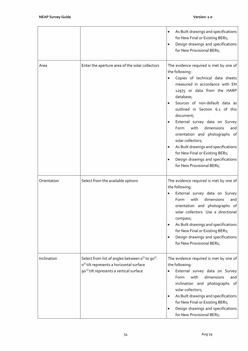
NEAP Survey Guide Version: 2.0
54 Aug 19
• As Built drawings and specifications
for New Final or Existing BERs;
• Design drawings and specifications
for New Provisional BERs;
Area Enter the aperture area of the solar collectors
The evidence required is met by one of
the following:
• Copies of technical data sheets
measured in accordance with EN
12975 or data from the HARP
database;
• Sources of non-default data as
outlined in Section 6.1 of this
document;
• External survey data on Survey
Form with dimensions and
orientation and photographs of
solar collectors;
• As Built drawings and specifications
for New Final or Existing BERs;
• Design drawings and specifications
for New Provisional BERs;
Orientation Select from the available options The evidence required is met by one of
the following:
• External survey data on Survey
Form with dimensions and
orientation and photographs of
solar collectors. Use a directional
compass;
• As Built drawings and specifications
for New Final or Existing BERs;
• Design drawings and specifications
for New Provisional BERs;
Inclination Select from list of angles between 0O to 90O.
0O tilt represents a horizontal surface
90 O tilt represents a vertical surface
The evidence required is met by one of
the following:
• External survey data on Survey
Form with dimensions and
inclination and photographs of
solar collectors;
• As Built drawings and specifications
for New Final or Existing BERs;
• Design drawings and specifications
for New Provisional BERs;

NEAP Survey Guide Version: 2.0
55 Aug 19
Do you know the
collector performance
parameters from EN
12975-2
The default values are used based on the
collector selected if it is not possible to obtain
the performance parameters for the collector.
The evidence required is met by one of
the following:
• Photographs of solar collectors
with nameplate and manufacturer’s
data sheets measured to EN 12975-
2 by a body with relevant
accreditation or data from the
HARP database;
• Sources of efficiency as outlined in
Section 6.1 of this document;
• Copies of technical data sheets
from Operational and Maintenance
Manual measured to EN 12975-2 by
a body with relevant accreditation;
• As Built drawings and specifications
for New Final or Existing BERs;
• Design drawings and specifications
for New Provisional BERs;
Solar Storage The dedicated solar storage volume associated
with the solar panel, insulation type and
thickness are entered.
Appendix 9 of this document provides guidance
on determining the storage volume of storage
units when manufacturers data is not available,
while Section 3.5.4 of How to use iSBEMie
(Volume 2) gives criteria for determining the
dedicated solar storage volume for various
arrangements.
In conjunction with the plantroom
survey details, the evidence required is
met by one of the following:
• Photographs of HWS Cylinders and
nameplates and manufacturer
name and manufacturer’s data
sheet;
• Copies of technical data sheets
from operational and maintenance
manuals;
• As Built drawings and specifications
for New Final or Existing BERs;
• Design drawings and specifications
for New Provisional BERs;
• Hot water storage volume
measured on site (and evidence of
any calculations retained by the
Assessor)
Do you know the heat
transfer rate of the
heat exchanger in the
collector loop?
Enter “There is no heat exchanger” if the system
is a direct system.
Enter “No, use the default” if there is a heat
exchanger and it is not possible to obtain the
performance data for the heat exchanger.
Enter “Yes, value is...” if the value is known.
Refer to Section 3.5.4 of How to use iSBEMie
(Volume 2) for guidance.
In conjunction with the plantroom
survey details, the evidence required is
met by one of the following:
• Photographs of HWS Cylinders and
nameplates and manufacturer
name and manufacturer’s data
sheet;

NEAP Survey Guide Version: 2.0
56 Aug 19
• Copies of technical data sheets
from operational and maintenance
manuals;
• As Built drawings and specifications
for New Final or Existing BERs;
• Design drawings and specifications
for New Provisional BERs;
Do you know the
overall heat loss
coefficient of all pipes
in the collector loop?
Enter “No, use the default” if it is not possible to
obtain the performance data for the pipework in
the collector loop.
Enter “Yes, value is” if the value is known.
Refer to Section 3.5.4 of How to use iSBEMie
(Volume 2) for guidance.
In conjunction with the plantroom
survey details, the evidence required is
met by one of the following along with
provision of representative
photographs of the pipework:
• Copies of technical data sheets
from operational and maintenance
manuals;
• As Built drawings and specifications
for New Final or Existing BERs;
• Design drawings and specifications
for New Provisional BERs;
Are the distribution
pipes between the SES
and the back-up
system insulated?
This only becomes active if there is a separate solar cylinder to the HWS cylinder.
In conjunction with the plantroom
survey details, the evidence required is
met by one of the following:
• Photographs of pipework;
• As Built drawings and specifications
for New Final or Existing BERs;
• Design drawings and specifications
for New Provisional BERs;
Auxiliary Energy
Consumption
Select from the circulation systems listed in the database.
In conjunction with the plantroom
survey details, the evidence required is
met by one of the following:
• Photographs of pumps and
nameplates and manufacturer
name and manufacturer’s data
sheet;
• Copies of technical data sheets
from operational and maintenance
manuals;
• As Built drawings and specifications
for New Final or Existing BERs;
• Design drawings and specifications
for New Provisional BERs;

NEAP Survey Guide Version: 2.0
57 Aug 19
7.19 iSBEMie Software Tab: “Building Services > PVS”
Data Entry Item Guidance Documentary Evidence
Type:
Enter if peak power is
NOT known
Select from the list of PV types.
• Mono crystalline silicon
• Multi crystalline silicon
• Multi-layer thin film amorphous silicon
• Other thin film layers
• Thin film copper-indium-gallium-diselenide
• Thin film cadmium-telluride
The assessor should select “Other thin film
layers” if type is not known.
In conjunction with the plantroom
survey details, the evidence required is
met by one of the following:
• Photographs of PV panels and
nameplates and manufacturer
name and manufacturer’s data
sheet;
• Copies of technical data sheets
from operational and maintenance
manuals;
• As Built drawings and specifications
for New Final or Existing BERs;
• Design drawings and specifications
for New Provisional BERs;
Area
Enter if peak power is
NOT known
Enter the Area of the PV The evidence required is met by one of
the following:
• Photographs of Photovoltaics and
copies of technical data sheets
from manufacturer;
• Photographs of Photovoltaics and
External survey data on Survey
Form with dimensions and
orientation;
• As Built drawings and specifications
for New Final or Existing BERs;
• Design drawings and specifications
for New Provisional BERs;
Peak Power Where there is sufficient data available, the peak
power may be entered directly as an alternative
to iSBEMie calculating the peak power based on
the array type and area.
The evidence required is met by one of
the following:
• Photographs of Photovoltaics and
copies of technical data sheets
from manufacturer in compliance
with standard, refer to Section 6.1
of this document;
• As Built drawings and specifications
for New Final or Existing BERs;
• Design drawings and specifications
for New Provisional BERs;
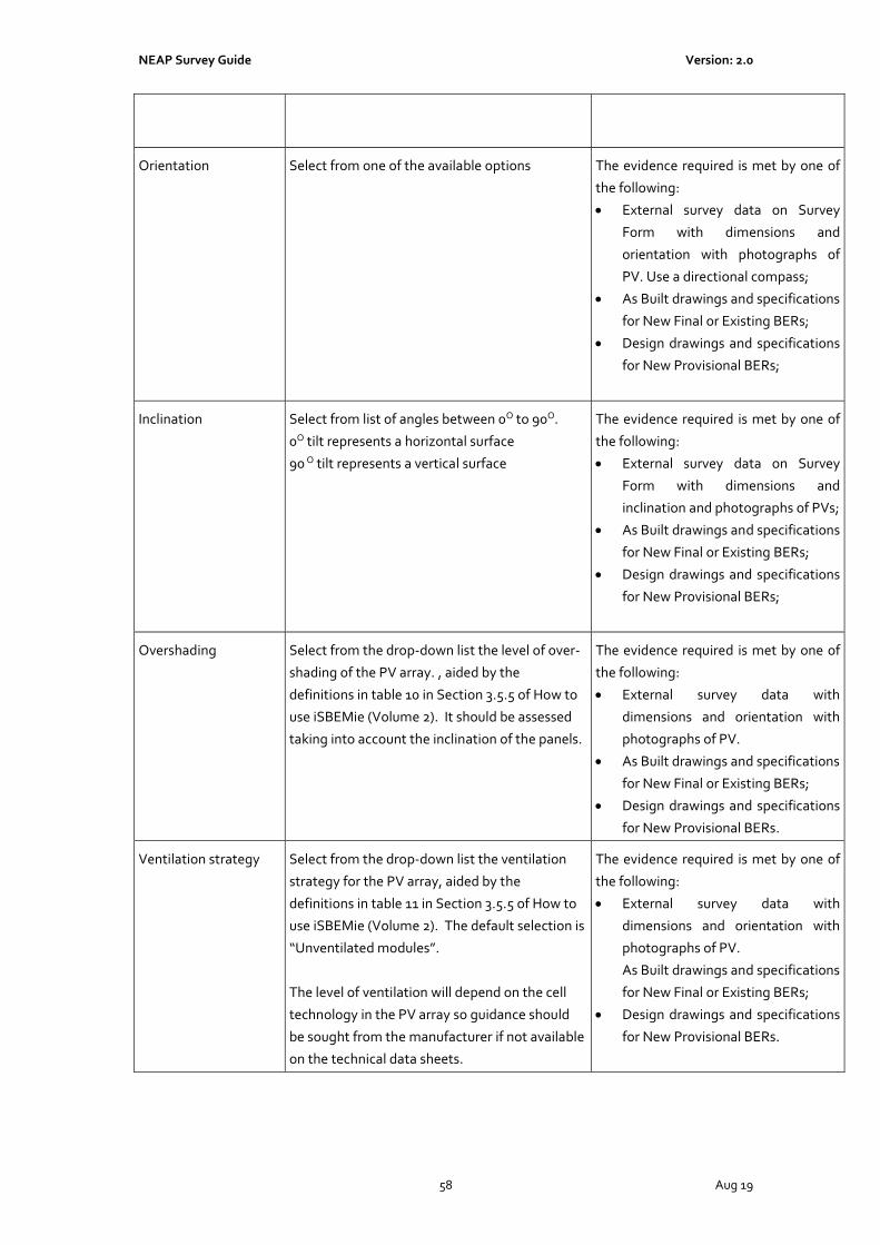
NEAP Survey Guide Version: 2.0
58 Aug 19
Orientation Select from one of the available options The evidence required is met by one of
the following:
• External survey data on Survey
Form with dimensions and
orientation with photographs of
PV. Use a directional compass;
• As Built drawings and specifications
for New Final or Existing BERs;
• Design drawings and specifications
for New Provisional BERs;
Inclination Select from list of angles between 0O to 90O.
0O tilt represents a horizontal surface
90 O tilt represents a vertical surface
The evidence required is met by one of
the following:
• External survey data on Survey
Form with dimensions and
inclination and photographs of PVs;
• As Built drawings and specifications
for New Final or Existing BERs;
• Design drawings and specifications
for New Provisional BERs;
Overshading Select from the drop-down list the level of over-
shading of the PV array. , aided by the
definitions in table 10 in Section 3.5.5 of How to
use iSBEMie (Volume 2). It should be assessed
taking into account the inclination of the panels.
The evidence required is met by one of
the following:
• External survey data with
dimensions and orientation with
photographs of PV.
• As Built drawings and specifications
for New Final or Existing BERs;
• Design drawings and specifications
for New Provisional BERs.
Ventilation strategy Select from the drop-down list the ventilation
strategy for the PV array, aided by the
definitions in table 11 in Section 3.5.5 of How to
use iSBEMie (Volume 2). The default selection is
“Unventilated modules”.
The level of ventilation will depend on the cell
technology in the PV array so guidance should
be sought from the manufacturer if not available
on the technical data sheets.
The evidence required is met by one of
the following:
• External survey data with
dimensions and orientation with
photographs of PV.
As Built drawings and specifications
for New Final or Existing BERs;
• Design drawings and specifications
for New Provisional BERs.

NEAP Survey Guide Version: 2.0
59 Aug 19
7.20 iSBEMie Software Tab: “Building Services > Wind Generators”
Data Entry Item Guidance Documentary Evidence
Terrain Type Select from the list of Terrain types. In conjunction with the external survey
details, the evidence required is met by
one of the following:
• Photographs of surrounding sites;
• Site plan showing surrounding
sites.
Horizontal Axis -
Diameter
Enter the Diameter of the Wind Turbine The evidence required is met by one of
the following:
• Copies of technical data sheets
from manufacturer;
• External survey data on Survey
Form with dimensions and
photographs of wind turbines;
As Built drawings and specifications
for New Final or Existing BERs;
• Design drawings and specifications
for New Provisional BERs.
Others - Area Enter the Area Swept by the rotor blades. Refer
to Section 3.5.6 of How to use iSBEMie (Volume
2) for details
The evidence required is met by one of
the following:
• Copies of technical data sheets
from manufacturer;
• External survey data on Survey
Form with dimensions and
photographs of wind turbines;
As Built drawings and specifications
for New Final or Existing BERs;
• Design drawings and specifications
for New Provisional BERs.
Height Enter the height by the wind turbine. Refer to
Section 3.5.6 of How to use iSBEMie (Volume 2)
for details.
The evidence required is met by one of
the following:
• Copies of technical data sheets
from manufacturer;
• External survey data on Survey
Form with dimensions and
photographs of wind turbines;
As Built drawings and specifications
for New Final or Existing BERs;
• Design drawings and specifications
for New Provisional BERs.
kW Enter the wind turbine rated power The evidence required is met by one of
the following:
• Copies of technical data sheets

NEAP Survey Guide Version: 2.0
60 Aug 19
from manufacturer and
photographs of wind turbines
nameplate;
As Built drawings and specifications
for New Final or Existing BERs;
• Design drawings and specifications
for New Provisional BERs.
7.21 iSBEMie Software Tab: “Building Services > CHP generator”
Data Entry Item Guidance Documentary Evidence
Fuel Type Select from the Fuel Types In conjunction with the plantroom
survey details, the evidence required is
met by one of the following:
• Photographs of CHP nameplates
and manufacturer name and
manufacturer’s data sheets;
• Copies of technical data sheets
from operational and maintenance
manuals;
As Built drawings and specifications
for New Final or Existing BERs;
• Design drawings and specifications
for New Provisional BERs.
Heat Efficiency Seasonal thermal efficiency of the CHP
generator, defined as the total annual useful
heat supplied by the generator divided by the
total annual fuel energy input to the generator
(using the gross calorific value).
In conjunction with the plantroom
survey details, the evidence required is
met by one of the following:
• Photographs of CHP nameplates
and manufacturer name and
manufacturer’s data sheets in
compliance with the national
standards or the CHP EU directive
or EN 15316-4-4;
• Sources of efficiency as outlined in
Section 6.1 of this document;
• Copies of technical data sheets
from operational and maintenance
manuals;
As Built drawings and specifications
for New Final or Existing BERs;
• Design drawings and specifications
for New Provisional BERs.
Electrical Efficiency Total annual electric power output by the CHP
divided by the total annual fuel energy input
(using the gross calorific value).
In conjunction with the plantroom
survey details, the evidence required is
met by one of the following:

NEAP Survey Guide Version: 2.0
61 Aug 19
• Photographs of CHP nameplates
and manufacturer name and
manufacturer’s data sheets in
compliance with the national
standards or the CHP EU directive
or EN 15316-4-4;
• Sources of efficiency as outlined in
Section 6.1 of this document;
• Copies of technical data sheets
from operational and maintenance
manuals;
As Built drawings and specifications
for New Final or Existing BERs;
• Design drawings and specifications
for New Provisional BERs.
Building Space Heat
Supplied
Ascertain the proportion of space heating
supplied to the building by the CHP plant.
For existing buildings, a report from the
Building Operator detailing the
proportion of space heating supplied to
the building by the CHP plant.
Where submetering of the heat is
unavailable, the report should be based
on actual fuel consumption converted
into heat consumption based on the
actual plant performances for a 12-
month period. This method is only
acceptable when there is no “heat
dump”
For new buildings, a report signed by
engineers from the Design Team,
detailing the predicted proportion of
space heating supplied by the CHP
plant.
Building Hot Water
Supplied
Ascertain the proportion of hot water heating
supplied to the building by the CHP plant.
For existing buildings, a report from the
Building Operator detailing the
proportion of hot water supplied to the
building by the CHP plant.
Where submetering of the hot water is
unavailable, the report should be based
on actual fuel consumption converted
into hot water consumption based on
the actual plant performances for a 12-
month period. This method is only
acceptable when there is no “heat
dump”.
For new buildings, a report signed by
engineers from the Design Team,

NEAP Survey Guide Version: 2.0
62 Aug 19
detailing the predicted proportion of
hot water supplied by the CHP plant.
Tick this box for
Trigeneration systems
Ascertain if the building has a Trigeneration
system.
In conjunction with the plantroom
survey details, the evidence required is
met by one of the following:
• Photographs of CHP nameplates
and manufacturer name and
photographs of cooling System
(absorption chiller and nameplate);
• Copies of technical data sheets
from operational and maintenance
manuals;
As Built drawings and specifications
for New Final or Existing BERs;
• Design drawings and specifications
for New Provisional BERs.
Building Cooling
Supplied
The Assessor must ascertain the proportion of
cooling supplied to the building by the
Trigeneration system
For existing buildings, a report from the
Building Operator detailing the
proportion of cooling supplied to the
building by the Trigeneration.
Where submetering of the chilled water
is unavailable, the report should be
based on running time for the plant
over a 12-month period and the actual
plant performances.
For new buildings, a report signed by
engineers from the Design Team,
detailing the predicted proportion of
space cooling supplied by the CHP.
Chiller Efficiency The seasonal chiller efficiency of the generator,
defined as the cooling demand divided by the
cooling energy for the generator.
In conjunction with the plantroom
survey details, the evidence required is
met by one of the following:
• Photographs of CHP nameplates
and manufacturer name and
photographs of cooling System
(absorption chiller nameplate) and
manufacturer’s data sheets;
• Copies of technical data sheets
from operational and maintenance
manuals;
• Sources of efficiency as outlined in
Section 6.1 of this document;

NEAP Survey Guide Version: 2.0
63 Aug 19
As Built drawings and specifications
for New Final or Existing BERs;
• Design drawings and specifications
for New Provisional BERs.
7.22 iSBEMie Software Tab: “Building Services > Zones > Solar Collectors”
Data Entry Item Guidance Documentary Evidence
Solar Collector
Parameters
Refer to Section 3.5.8 of How to use iSBEMie
(Volume 2) for details on data entry.
Note: The user must define specific wall
elements in the Project database to represent
“non-transpired” solar collectors which form
part of the building structure as opposed to
add-on equipment.
The evidence required is met by one of
the following:
• Photographs of solar collectors and
copies of technical data sheets
from manufacturer;
• Photographs of solar collectors and
External survey data on Survey
Form with dimensions and
orientation;
As Built drawings and specifications
for New Final or Existing BERs;
• Design drawings and specifications
for New Provisional BERs.
7.23 iSBEMie Software Tab: “Building Services > Zones > HVAC, HWS & Lighting Systems”
Data Entry Item Guidance Documentary Evidence
Deadleg Length in this
zone
Length of draw off pipe to the outlet in the
space (only used in zones where the water is
drawn off).
The deadleg distance is measured from the
edge of the zone or from the storage vessel/
circulation in the zone to the outlet point.
Where pipework is not visible in the zone and
drawings are unavailable, allow for the deadleg
running from the edge of the zone or from the
storage vessel/ circulation in the zone to the
outlet point.
The evidence required is met by one of
the following:
As Built mechanical drawings
marked up to show zones for New
Final or Existing BERs;
• Design drawings and specifications
for New Provisional BERs.
• Sketches of zones/ pipework
showing dimensions.
• Photographs of pipework.
7.24 iSBEMie Software Tab: “Building Services > Zones > Ventilation”
Data Entry Item Guidance Documentary Evidence

NEAP Survey Guide Version: 2.0
64 Aug 19
Zonal Ventilation Type If not previously included in the HVAC system,
the Assessor may select “Natural” or
“Mechanical Supply/Extract” to a zone.
In situations where the supply and extract
elements of a ventilation system are located in
different zones, but form one system, enter
that both zones have mechanical supply/
extract ventilation. An example might be air
supplied to a corridor outside a toilet and then
extracted in the toilet. Can also occur in
healthcare zones such as operating theatres.
In conjunction with the floor by floor
sketches, the evidence required is met
by one of the following:
As Built mechanical drawings
marked up to show zones for New
Final or Existing BERs;
• Design drawings and specifications
for New Provisional BERs;
• Survey Form and photographs.
Do you know the
Supply/ Extract SFP?
There is an onus on the Assessor to make
reasonable efforts to find and use the fan
details and to resort to the default value only if
the information is not available.
The SFP must be calculated in accordance with
the procedure set out in IS EN 13779:2007
Annex D Calculation and Appendix E of the
TGD Part L 2017 – Buildings Other than
Dwellings.
Non-default efficiencies may be obtained from
the following sources:
• Performance data on “CE marked”
literature is acceptable provided that the literature refers to the relevant test performance standard.
• Literature from manufacturer referencing the efficiency and relevant test performance standard.
• Accredited Test certificates to the relevant test performance standard.
The evidence required is met by one of
the following:
• Photographs of fan nameplates
and manufacturer’s data sheets;
• Sources of efficiency as outlined in
Section 6.1 of this document;
• Copies of technical data sheets
from operational and maintenance
manuals;
As Built drawings and specifications
for New Final or Existing BERs;
• Design drawings and
specifications for New Provisional
BERs;
Calculations of SFP must be retained
in all cases.
Does activity require
high pressure drop air
treatment
The Assessor must ascertain if high pressure
drop air treatment is required or alternatively
use the default based on selected activity.
If non-default values are used the
Assessor must obtain drawings and
specification showing high pressure
drop air treatment.
Demand Controlled
Ventilation
The Assessor may select the type of control for
Demand Controlled Ventilation in a zone if it is
present.
The evidence required is met by one of
the following:
• Photographs of ventilation
system and controls including

NEAP Survey Guide Version: 2.0
65 Aug 19
either photographs of relevant
sensors or photograph of BMS
showing sensors
• Copies of technical data sheets
from operational and maintenance
manuals;
• As Built drawings and specifications
for New Final or Existing BERs;
• Design drawings and
specifications for New Provisional
BERs;
Ventilation - Heat
Recovery
The heat recovery system may be incorporated
within the air handling unit(s) or it may be
external.
The Assessor must establish whether or not
heat recovery is fitted
For New Final and Existing BERs, in
conjunction with the plantroom survey
details, the evidence required is met by
one of the following:
• Photographs of heat recovery unit;
• Copies of technical data sheets
from operational and maintenance
manuals
• As Built drawings and
specifications.
For New Provisional BERs, design
drawings and specifications.
Tick if variable heat
recovery efficiency
Tick box if documentary evidence is available
to show that the heat recovery system can be
bypassed or switched off in summer.
For New Final and Existing BERs, in
conjunction with the plantroom survey
details, the evidence required is met by
one of the following:
• Photographs of bypass/ controls;
• Copies of technical data sheets
from operational and maintenance
manuals
• As Built drawings and
specifications.
For New Provisional BERs, design
drawings and specifications.
Heat Recovery
Seasonal Efficiency
The default value must be used for efficiency if
there is no documentary evidence to
substantiate non-default entries.
For New Final and Existing BERs, in
conjunction with the plantroom survey
details, the evidence required is met by
one of the following:

NEAP Survey Guide Version: 2.0
66 Aug 19
A non-default value should be used where
possible. Non-default efficiency values must be
in compliance with the Commission Regulation
(EU) 1253/2014 with regard to Ecodesign
requirements for ventilation units.
Non-default efficiencies may be obtained from
the following sources as per Section 6.1:
• Performance data on “CE marked” literature is acceptable provided that the literature refers to the relevant test performance standard.
• Literature from manufacturer referencing the efficiency and relevant Ecodesign standard.
• Accredited Test certificates to the relevant test performance standard
• Photographs of heat recovery unit;
• Copies of technical data sheets
from operational and maintenance
manuals
• Sources of efficiency as outlined in
“Guidance” and Section 6.1;
• As Built drawings and
specifications.
For New Provisional BERs, design
drawings, specifications and sources of
efficiency as outlined in “Guidance” and
Section 6.1.
Tick Box for Night
Cooling
The Assessor may select that there is Night
Cooling provided in a zone.
For New Final and Existing BERs, in
conjunction with the plantroom survey
details, the evidence required is met by
one of the following:
• Photographs of controls
demonstrating night cooling;
• Copies of technical data sheets
from operational and maintenance
manuals
For New Provisional BERs, design
specifications
Max Hours of Night
Cooling (NC) per
month
Where documentary evidence is available,
enter the maximum number of hours per
month during which night cooling is operating
in the zone.
For New Final and Existing BERs, in
conjunction with the plantroom survey
details, the evidence required is met by
one of the following:
• Photographs of controls
demonstrating night cooling
operational hours;
• Copies of technical data sheets
from operational and maintenance
manuals demonstrating night
cooling operation hours
For New Provisional BERs, design
specifications

NEAP Survey Guide Version: 2.0
67 Aug 19
Max flow rate during
Night Cooling (NC)
hours
Where documentary evidence is available
enter the max. flow rate during NC hours - This
is the maximum air flow rate in the zone, in
l/s.m2 of floor area, during the operation of
night cooling.
For New Final and Existing BERs, in
conjunction with the plantroom survey
details, the evidence required is met by
one of the following:
• Copies of technical data sheets
from operational and maintenance
manuals demonstrating the
commissioned night cooling flow
rate
For New Provisional BERs, design
specifications
Specific Fan Power for
Night Cooling
There is an onus on the Assessor to make
reasonable efforts to find and use the fan
details and to resort to the default value only if
the information is not available.
The SFP must be calculated in accordance with
the procedure set out in IS EN 13779:2007
Annex D Calculation and Appendix E of the
TGD Part L 2017 – Buildings Other than
Dwellings.
Non-default efficiencies may be obtained from
the following sources:
• Performance data on “CE marked”
literature is acceptable provided that the literature refers to the relevant test performance standard.
• Literature from manufacturer referencing the efficiency and relevant test performance standard.
Accredited Test certificates to the relevant test
performance standard.
The evidence required is met by one of
the following:
• Photographs of fan nameplates
and manufacturer’s data sheets;
• Sources of efficiency as outlined in
Section 6.1 of this document;
• Copies of technical data sheets
from operational and maintenance
manuals;
As Built drawings and specifications
for New Final or Existing BERs;
• Design drawings and
specifications for New Provisional
BERs;
Calculations of SFP must be retained in
all cases.
Specific Fan Power for
the system terminal
Units
This parameter becomes active if the HVAC system type serving the zone is selected to
be 'Fan coil systems' or 'Indoor packaged
cabinet (VAV). It allows users to enter the SFP
for the terminal unit(s) in the zone.
The SFP must be calculated in accordance with
the procedure set out in IS EN 13779:2007
The evidence required is met by one of
the following:
• Photographs of fan nameplates
and manufacturer’s data sheets;
• Sources of efficiency as outlined in
Section 6.1 of this document;
• Copies of technical data sheets
from operational and maintenance
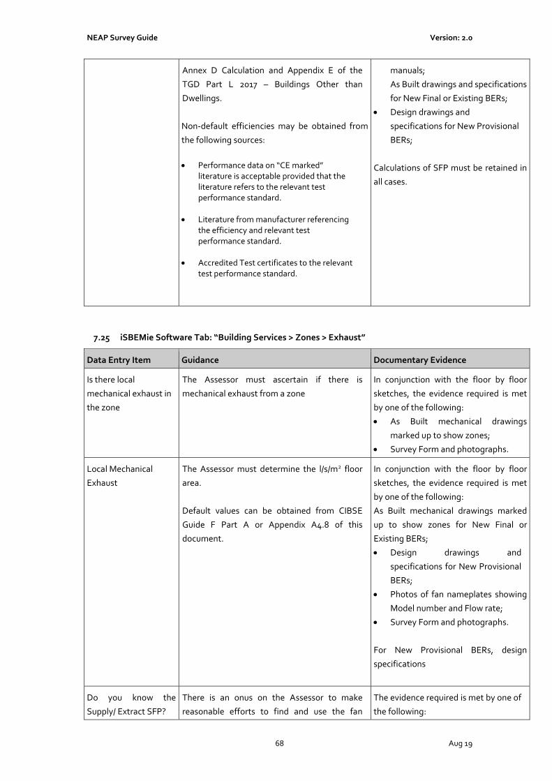
NEAP Survey Guide Version: 2.0
68 Aug 19
Annex D Calculation and Appendix E of the
TGD Part L 2017 – Buildings Other than
Dwellings.
Non-default efficiencies may be obtained from
the following sources:
• Performance data on “CE marked”
literature is acceptable provided that the literature refers to the relevant test performance standard.
• Literature from manufacturer referencing the efficiency and relevant test performance standard.
• Accredited Test certificates to the relevant test performance standard.
manuals;
As Built drawings and specifications
for New Final or Existing BERs;
• Design drawings and
specifications for New Provisional
BERs;
Calculations of SFP must be retained in
all cases.
7.25 iSBEMie Software Tab: “Building Services > Zones > Exhaust”
Data Entry Item Guidance Documentary Evidence
Is there local
mechanical exhaust in
the zone
The Assessor must ascertain if there is
mechanical exhaust from a zone
In conjunction with the floor by floor
sketches, the evidence required is met
by one of the following:
• As Built mechanical drawings
marked up to show zones;
• Survey Form and photographs.
Local Mechanical
Exhaust
The Assessor must determine the l/s/m2 floor
area.
Default values can be obtained from CIBSE
Guide F Part A or Appendix A4.8 of this
document.
In conjunction with the floor by floor
sketches, the evidence required is met
by one of the following:
As Built mechanical drawings marked
up to show zones for New Final or
Existing BERs;
• Design drawings and
specifications for New Provisional
BERs;
• Photos of fan nameplates showing
Model number and Flow rate;
• Survey Form and photographs.
For New Provisional BERs, design
specifications
Do you know the
Supply/ Extract SFP?
There is an onus on the Assessor to make
reasonable efforts to find and use the fan
The evidence required is met by one of
the following:

NEAP Survey Guide Version: 2.0
69 Aug 19
details and to resort to the default value only if
the information is not available.
The SFP must be calculated in accordance with
the procedure set out in IS EN 13779:2007
Annex D Calculation and Appendix E of the
TGD Part L 2017 – Buildings Other than
Dwellings.
Non-default efficiencies may be obtained from
the following sources:
• Performance data on “CE marked”
literature is acceptable provided that the literature refers to the relevant test performance standard.
• Literature from manufacturer referencing the efficiency and relevant test performance standard.
• Accredited Test certificates to the relevant test performance standard.
• Photographs of fan nameplates
and manufacturer’s data sheets;
• Sources of efficiency as outlined in
Section 6.1 of this document;
• Copies of technical data sheets
from operational and maintenance
manuals;
As Built drawings and specifications
for New Final or Existing BERs;
• Design drawings and
specifications for New Provisional
BERs;
.
Calculations of SFP must be retained
in all cases.
7.26 iSBEMie Software Tab: “Building Services > Zones > Lighting”
Data Entry Item Guidance Documentary Evidence
What information is
available on Lighting?
The design illuminance, in lux is entered here. If
there is no such data available, the field is left
blank.
The Assessor has a choice on how the wattage is
entered.
Select from:
• Full lighting design carried out
• Lighting chosen but calculation not
carried out
• Lighting Paramenters not available
Refer to the individual sections below.
• As Built drawings and specifications
and lighting calculations for New
Final or Existing BERs;
• Design drawings and
specifications and lighting
calculations for New Provisional
BERs;
• Photographs of Lighting and
Lighting Controls.

NEAP Survey Guide Version: 2.0
70 Aug 19
Full lighting design
carried out
Total wattage: This value should be for the
lighting system, i.e., it includes the luminaires
and ballasts (control gear).
The total wattage should be for the fixed light
fittings only. Where task lighting is “plug in”
lighting it should not be included in the model.
It is recommended that the actual lighting type
be entered in the “Lighting Parameters not
available” field as it will change
recommendations on the Advisory Report.
In order to use the “Full lighting design
carried out” entry the Assessor must
have a signed statement from a
suitably qualified consultant (normally
the M&E engineers) responsible for
the lighting design showing:
In the case of a Provisional BER, the
design power and design illuminance
for each of the zones.
In the case of a New Final and Existing
BER,
• the installed power and installed
illuminance for each of the zones.
• photographs of lighting and
lighting controls.
When information is insufficient for a
particular zone the data entry must be
made using the other data entry
method below.
Lighting chosen but
calculation not carried
out
Both fields require data entry.
Lamp lumens per circuit wattage: This is the
value in lumens for the lamp / bulb in the fitting.
The lamp lumen per circuit wattage should be
for the fixed light fittings only. Where task
lighting is “plug in” lighting it should not be
included in the model.
Light output ratio (LOR): This value between 0.1
and 1.0 represents the efficiency of the luminaire
/ fitting to distribute the light from the lamp /
bulb.
Note: If the value available is the luminous
efficacy of the luminaire, rather than that of the
lamp, then you can enter the luminaire value
into iSBEMie with a LOR of 1.0
“Control Factors” should not be included in
calculations.
It is recommended that the actual lighting type
In conjunction with the floor by floor
sketches, the evidence required is met
by Manufacturers Data Sheets plus the
following:
• As Built Electrical Lighting
Drawings marked up to show zones
for New Final and Existing
Buildings;
• Design Electrical Lighting
Drawings and Specification marked
up to show zones for New
Provisional
• Survey Form
• Photographs of light fittings.
Photograph(s) of each light type
should be provided.
When information is insufficient for a
particular zone the data entry must be
made using the “Lighting Parameters
not available” data entry method
below.

NEAP Survey Guide Version: 2.0
71 Aug 19
be entered in the “Lighting Parameters not
available” field as it will change
recommendations on the Advisory Report.
Lighting Parameters
not available
Determine the lamp type for each zone. Where
the specific fitting cannot be identified, take
the most conservative (lowest lumens per
circuit watt) option from Table 12 in How to
use iSBEMie (Volume 2)
Note: The “Don’t know” option is no longer
available. In situations where the lighting type
is unknown “Tungsten” is assumed.
Refer to Appendix 11 of this document for
guidance on selection of lamp type.
Refer to Appendix 4.7 of this document for the
details on how Shell and Core buildings are dealt
with.
Where a combination of lighting systems is
present in the zone providing general lighting
(no display lighting), the zone should be split to
reflect the lamp locations.
Where a combination of lighting systems is
present in the zone providing general lighting
(no display lighting) across the entire zone, such
that splitting the zone to reflect the lamps
location is not practicable (For example the zone
contains a combination of fluorescents and LED
down lighters mixed throughout the zone) then
the average performance is determined as
follows:
• The proportion of the zone’s area lit by each
lamp type is established.
• Calculate average performance based on
Table 12 of iSBEM User Guide. For example,
assuming 60% of floor area is fluorescents,
22.5 lumen/cW from Table 12 and 40% of
floor area is LED, 50 lumen/cW
0.6 x 22.5 + 0.4 x 50 = 33.5
• Select equivalent lamp from Table 12, ie
closest performance below value. In this case
In conjunction with the floor by floor
sketches, the evidence required is met
by the following:
• As Built Electrical Lighting
Drawings marked up to show zones
for New Final and Existing
Buildings;
• Design Electrical Lighting
Drawings and Specification marked
up to show zones for New
Provisional
• Survey Form
• Photographs of light fittings.
Photograph(s) of each light type
should be provided.

NEAP Survey Guide Version: 2.0
72 Aug 19
T8 Fluorescent – halophosphate – high
frequency ballast.
Are air extracting
luminaires fitted
The Assessor must determine if air extracting
luminaires are fitted.
In conjunction with the floor by floor
sketches, the evidence required is met
by the following:
• As Built Electrical Lighting
Drawings marked up to show
zones;
• Survey Form and photographs of
light fittings.
7.27 iSBEMie Software Tab: “Building Services > Zones > Lighting Controls”
Data Entry Item Guidance Documentary Evidence
Lighting Controls The Assessor must determine the lighting
controls within the zone.
In conjunction with the floor by floor
sketches, the evidence required is met
by the following:
• As Built Electrical Lighting
Drawings marked up to show zones
for New Final and Existing
Buildings;
• Design Electrical Lighting
Drawings and Specification marked
up to show zones for New
Provisional
• Survey Form
• Photographs of lighting controls.
Local Manual
Switching
Determine if occupants can control the
luminaries individually and if light switch is
within 6m of the luminaries it controls.
In conjunction with the floor by floor
sketches, the evidence required is met
by the following:
• As Built Electrical Lighting
Drawings marked up to show zones
for New Final and Existing
Buildings;
• Design Electrical Lighting
Drawings and Specification marked
up to show zones for New
Provisional
• Survey Form
• Photographs of lighting switches.

NEAP Survey Guide Version: 2.0
73 Aug 19
Photoelectric Options Determine the type of switching, whether a
different sensor controls the back of the zone,
the type of sensor and the Parasitic Power of
the sensor.
Refer to Section 3.5.9 of How to use iSBEMie
(Volume 2). Establish whether or not the
sensor has a photoelectric function, by carrying
out on site tests or obtaining technical data
sheets detailing the light control functions in
each zone.
In conjunction with the floor by floor
sketches, the evidence required is met
by one of the following:
• As Built electrical lighting drawings
and specification marked up to
show zones for New Final and
Existing Buildings;
• Design Electrical Lighting
Drawings and Specification marked
up to show zones for New
Provisional
• Survey Form
• Photographs of lighting controls;
• Technical data sheets on the
lighting controls from Operational
and Maintenance manuals.
Photoelectric Options
– Parasitic Power
The parasitic power or the standby power is
the power required to operate the lighting
controls and detectors.
In conjunction with the floor by floor
sketches, the evidence required is met
by one of the following:
• Technical data sheets on the
lighting controls from Operational
and Maintenance manuals.
Occupancy Sensing Determine the type of Occupancy Sensing
Controls and the Parasitic Power of the sensor
Refer to Section 3.5.9 of How to use iSBEMie
(Volume 2).
In conjunction with the floor by floor
sketches, the evidence required is met
by one of the following:
• As Built electrical lighting drawings
and specification marked up to
show zones for New Final and
Existing Buildings;
• Design Electrical Lighting
Drawings and Specification marked
up to show zones for New
Provisional;
• Survey Form and photographs of
lighting controls;
• Technical data sheets on the
lighting controls from Operational
and Maintenance manuals.
Occupancy Sensing –
Parasitic Power
The parasitic power or the standby power is
the power required to operate the lighting
controls and detectors.
In conjunction with the floor by floor
sketches, the evidence required is met
by one of the following:
• Technical data sheets on the

NEAP Survey Guide Version: 2.0
74 Aug 19
lighting controls from Operational
and Maintenance manuals.
7.28 iSBEMie Software Tab: “Building Services > Zones > Display Lighting”
Data Entry Item Guidance Documentary Evidence
Does the display
lighting use efficient
lamps?
Is there time
switching?
This section becomes active when iSBEMie
assumes the presence of display lighting.
The following zone types are given display
lighting by iSBEMie:
Display Area, Retail Sales areas (all types),
Reception (all types of building), Consulting
Rooms and Operating Theatres.
The default power density used can be high and
so it is important to adjust the lamp luminous
efficacy if required.
Refer to Appendix 4.9 of this document for
guidance on reducing the power allocated in
the cases where the display lighting is “low
energy” or where none is actually present.
In conjunction with the floor by floor
sketches, the evidence required is met
by one of the following:
• As Built electrical lighting drawings
and specification marked up to
show zones;
• Survey Form and photographs of
lighting controls;
• Technical data sheets on the
lighting controls from the
operational and maintenance
manuals.

NEAP Survey Guide Version: 2.0
75 Aug 19
Appendix 1: The NEAP Survey Form
NEAP SURVEY FORMName: Assessor / BER reg. no.
Address: Survey Date:
MPRN Building Type
Age: Building Age: Extension 1 Age:Extension 2
Evidence 1 Evidence 2 No Extension No Extension number of storeys
Evidence 1 Evidence 2 Evidence 1 Evidence 2
Air Test ? Thermal Bridging ? Building Type(s) Type of Rating
Default 25 Default new-provisional
Cert available Data available new-final building
existing building
Wall construction Main Wall Type 1* Roof Construction: Main Roof* Ground Floor Construction: Main Floor*
Wall construction Wall Type 2* Roof Construction: Roof Type 2* Ground Floor Construction: Floor Type 2*
Wall construction Wall Type 3* Roof Construction: Roof Type 3* Internal Floor Construction: Floor Type 3*
Wall construction Wall Type 4* Construction: Type * Construction: Type *
Window Construction: Wall windows 1 Window Construction: Roof windows 1 Door Construction: Personnel door(s)*
Non-Default Data? N Y Non-Default Data? N Y
Material Alu PVC W Material Alu PVC W None Door make-up Type 1:
Thermal break N Y Thermal break N Y
Low E N Y Low E N Y
Argon Gas N Y Argon Gas N Y Door make-up Type 2:
Glazing make-up : Glazing make-up :
Window Construction: Wall windows 2 Window Construction: Wall windows 2 Door Construction: Vehicle Access door(s)
Non-Default Data? N Y Non-Default Data? N Y
Material Alu PVC W Material Alu PVC W Door make-up Type 1:
Thermal break N Y Thermal break N Y
Low E N Y Low E N Y
Gas Air / Other A O Gas Air / Other A O Door make-up Type 2:
Glazing make-up : Glazing make-up :
*note:Actual U-value should be calculated and used if the wall /roof /floor construction detail is available on site or through documentation.
Substantiation supporting the U-value calculation is required. Non default U values should be recorded along with relevant calculation in Assessor's records
Reprint this page as often as required (e.g. Multiple extensions or more than four wall types etc)

NEAP Survey Guide Version: 2.0
76 Aug 19
HVAC System Heating ONLY
HVAC System Heating System Fuel
[Ventilation can be applied in a zone if required] mains gas biomass Direct OR storage electric heater
Local Heating Systems (heat source in zone) LPG waste heat Room heater (Open fire, stove)
Other local room heater - fanned (b) Biogas Anthracite Flued Radiant heater
Other local room heater - unfanned Oil Smokeless Fuel Air heater
Unflued radiant heater (a) electricity Dual Fuel Appliances Heat pump Type:
Flued radiant heater (a) Coal Uses CHP Unflued radiant heater
Multiburner radiant heaters (a) Manufacturer / make / model number ECA/ETL,(ACA) Listed?
Flued forced-convection air heaters Boiler/ Heater : Yes No
Unflued forced-convection air heaters AHU:
Radiant Efficiency (a) Aux Energy (b) Other :
Default Default Heating System Efficiency
Non-Default Value Non-Default Value = Default before 1998 Open Fire Default
= kWh/kWh Default post 1998 Non-Default Value
Central Heating Systems [heating by water]
Central heating using water: radiators (c) Yes, Submetered Yes, M&T Alarm LTHW Boiler
Central heating using water: convectors (b), (c) No, Submetered No, M&T Alarm MTHW boiler
Central heating using water: floor heating (c) HTHW boiler
Lighting Metering Provision Heat pump air source
Aux Energy (b) Variable Speed Pumps? (c) Yes, Submetered Yes, M&T Alarm Heat pump ground / water source
Default No Const. Speed No, Submetered No, M&T Alarm District heating
kWh/kWh Yes LTHW Ventilation Heat Recovery (e) or by zone Heat Recovery Seasonal Efficiency
Sensor: P S M Plate heat exchanger Thermal wheel Default
Central Heating Systems [heating by air] (d),(e) Heat-pipes Run around coil Non Default Value
Central heating using air distribution Variable Heat Recovery Efficiency ? Specific Fan Power
Ventilation is included in this system Yes Default
Ductwork Leakage (d) AHU Leakage (d) No SFP: W/l/s
Default Default System Controls
Non Default Non Default Central Time Control Local Temperature Control
Class: Class: Optimum Start/ Stop Control Weather Compensation Control
Local Time Control
HVAC System Heating System Fuel
[Ventilation can be applied in a zone if required] mains gas biomass Direct OR storage electric heater
Local Heating Systems (heat source in zone) LPG waste heat Room heater (Open fire, stove)
Other local room heater - fanned (b) Biogas Anthracite Flued Radiant heater
Other local room heater - unfanned Oil Smokeless Fuel Air heater
Unflued radiant heater (a) electricity Dual Fuel Appliances Heat pump Type:
Flued radiant heater (a) Coal Uses CHP Unflued radiant heater
Multiburner radiant heaters (a) Manufacturer / make / model number ECA/ETL,(ACA) Listed?
Flued forced-convection air heaters Boiler/ Heater : Yes No
Unflued forced-convection air heaters AHU:
Radiant Efficiency (a) Aux Energy (b) Other :
Default Default Heating System Efficiency
Non-Default Value Non-Default Value = Default before 1998 Open Fire Default
= kWh/kWh Default post 1998 Non-Default Value
Central Heating Systems [heating by water]
Central heating using water: radiators (c) Yes, Submetered Yes, M&T Alarm LTHW Boiler
Central heating using water: convectors (b), (c) No, Submetered No, M&T Alarm MTHW boiler
Central heating using water: floor heating (c) HTHW boiler
Lighting Metering Provision Heat pump air source
Aux Energy (b) Variable Speed Pumps? (c) Yes, Submetered Yes, M&T Alarm Heat pump ground / water source
Default No Const. Speed No, Submetered No, M&T Alarm District heating
kWh/kWh Yes LTHW Ventilation Heat Recovery (e) Heat Recovery Seasonal Efficiency
Sensor: P S M Plate heat exchanger Thermal wheel Default
Central Heating Systems [heating by air] (d),(e) Heat-pipes Run around coil Non Default Value
Central heating using air distribution Variable Heat Recovery Efficiency ? Specific Fan Power
Yes Default
Ductwork Leakage (d) AHU Leakage (d) No SFP: W/l/s
Default Default System Controls
Non Default Non Default Central Time Control Local Temperature Control
Class: Class: Optimum Start/ Stop Control Weather Compensation Control
Local Time Control
Replicate this page as required if there are more than two Heating Only HVAC systems. See other worksheet for systems that include cooling.
Heating Source (Local Heating)
HVAC Metering Provision Heating Source (Central Heating)
HVAC SYSTEM TYPE 1 - HEATING ONLY
Heating Source (Local Heating)
HVAC Metering Provision Heating Source (Central Heating)
HVAC SYSTEM TYPE 2 - HEATING ONLY

NEAP Survey Guide Version: 2.0
77 Aug 19
HVAC System Heating AND Cooling
HVAC System Heating System Fuel
mains gas biomass LTHW Boiler
Local Cooling System (Cooling coil in zone) LPG waste heat MTHW boiler
Split or mulit-split system * Biogas Anthracite HTHW boiler
Single Room Cooling system * Oil Smokeless Fuel Heat pump air source
Fan Coil Units ** electricity Dual Fuel Appliances Heat pump ground / water source
Water Loop Heatpump [RARE] Coal Uses CHP District heating
Manufacturer / make / model number ECA/ETL,
Central Cooling System (Cooling coil on AHU) Boiler : (ACA) Listed?
Constant volume system (fixed fresh air rate) AHU: Yes No
Constant volume system (variable fresh air rate) Chiller or Indoor/Outdoor Units
Terminal reheat (constant volume) Heating System Efficiency Cooling System Efficiency
Dual duct (constant volume) Default before 1998 EER Default SEER Default
Chilled ceilings or passive chilled beams Default post 1998 EER Value : SEER Value :
Active chilled beams Non-Default Value
Single-duct VAV
Dual-duct VAV Yes, Submetered Yes, M&T Alarm Heatpump (electric)
Indoor packaged cabinet (VAV) No, Submetered No, M&T Alarm Heatpump (gas/ oil)
Multizone (hot deck/cold deck) [RARE] Lighting Metering Provision Air cooled chiller
Induction system [RARE] Yes, Submetered Yes, M&T Alarm Water cooled chiller
No, Submetered No, M&T Alarm Remote-condenser chiller
Applied in zones tab: Variable Speed Pumps? (c) Ventilation Heat Recovery Heat Recovery Seasonal Efficiency
* Ventilaton No Const. Speed Plate heat exchanger Thermal wheel Default
** Terminal Unit SFP Yes LTHW & CHW Heat-pipes Run around coil Non Default Value
Sensor: P S M Variable Heat Recovery Efficiency ? Specific Fan Power
Yes Default
Ductwork Leakage AHU Leakage No SFP: W/l/s
Default Default System Controls Mixed Mode Operation
Non Default Non Default Central Time Control Local Temperature Control Yes
Class: Class: Optimum Start/ Stop Control Weather Compensation Control No
Local Time Control
Replicate this page as required if there are more than two Heating & Cooling HVAC systems. See other worksheet for systems that can provide HEATING ONLY.
HVAC Metering Provision Cooling Source
Heating Source
Cooling Source
HVAC SYSTEM TYPE 3 - HEATING and COOLING
Heating Source
HVAC Metering Provision
HVAC SYSTEM TYPE 4 - HEATING and COOLING

NEAP Survey Guide Version: 2.0
78 Aug 19
Heating system (Hot Water System) Generator Type HWS System Fuel HWS System Age HWS System Efficiency
Dedicated hot water boiler mains gas biomass 1998 or later Default
Stand-alone water heater LPG waste heat pre 1998 Non Default
Instantaneous hot water only Biogas other: Manufacturer / make / model number
Instantaneous combi Oil
Heat pump electricity
Same as HVAC: Coal
Hot Water Cylinder Storage System Secondary Circulation
no access Insulation: no insulation storage losses circulation losses (W/m)
capacity (litres) lagging jacket insulation pump power (kW)
or dimensions factory fitted thickness (mm) MJ/month loop length (m)
time control on secondary circulation
Solar Water Heating Collector Parameters Manufacturer / make / model number
none aperture orientation evacuated tube
solar water heating present panel area (m2) flat plate, glazed
tilt o Unglazed
Non Default
Solar Storage Collector Loop
solar storage combined cylinder no insulation insulation Heat Transfer Rate of Heat Exchanger Heat Loss Coeff o f all P ipes
volume (litres) separate cylinder lagging jacket thickness no heat exchanger default
factory fitted (mm) default non default
non default
PhotovoltaicsParameters Manufacturer / make / model number
none Orientation Overshading
Use Peak Power None or very little (<20%)
Mono crystalline silicon Modest (20-60%)
Multi crystalline silicon Inclination Significant (60-80%)
Multi layer thin film amorphous silicon Heavy (>80%)
Other thin film layers Ventilation Strategy
Thin film copper-indium-gallium-diselenide Strongly ventilated or forced ventilated modules
Thin film cadmium-telluride Moderately ventilated modules
Area Unventilated modules
m2
Wind GeneratorParameters Manufacturer / make / model number
none Smooth flat country (no obstacles) horizontal height,m
turbine present Farm land with boundary hedges axis, m
Suburban or industrial area Swept power,kW
Urban w ith average building height > 15m Area, m2
CHPParameters Fuel Efficiency Heat Supplied Tri Generation
none mains gas biomass Heat Building Space Building Cooling
chp present LPG Anthracite Efficiency Heat Supplied, % Supplied, %
tri generation present Biogas Smokeless Fuel Electrical Building Hot Chiller
Oil Dual Fuel Appliances Efficiency Water Supplied, % Efficiency
Coal
Chiller Manufacturer / make / model number
Any other comments or details on assessment including items observed which affect the rating but not shown elsewhere on survey form/sketches.
Reprint this page if multiple CHP, DHW, Solar, PV or Wind systems present
CHP Manufacturer / make / model number
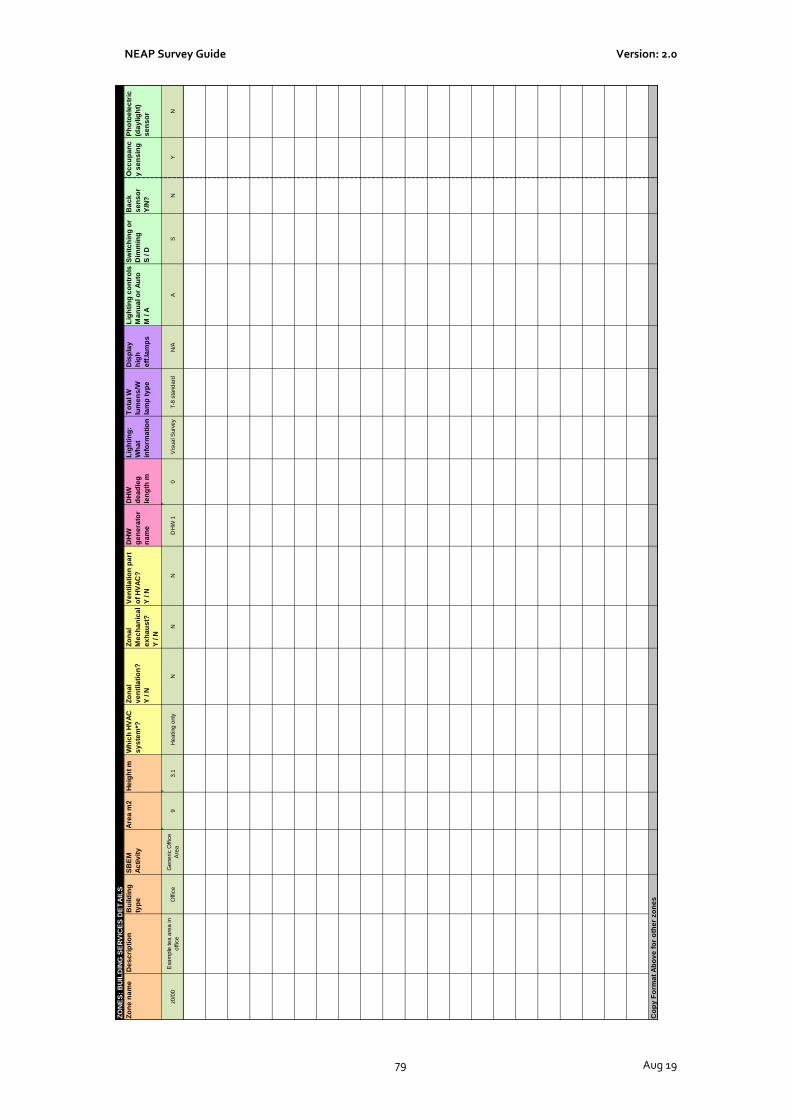
NEAP Survey Guide Version: 2.0
79 Aug 19
ZO
NE
S:
BU
ILD
ING
SE
RV
ICE
S D
ET
AIL
S
Zo
ne
na
me
De
sc
rip
tio
nB
uild
ing
typ
e
SB
EM
Ac
tiv
ity
Are
a m
2H
eig
ht
mW
hic
h H
VA
C
sy
ste
m*?
Zo
na
l
ve
nti
lati
on
?
Y / N
Zo
na
l
Me
ch
an
ica
l
ex
ha
us
t?
Y / N
Ve
nti
lati
on
pa
rt
of
HV
AC
?
Y / N
DH
W
ge
ne
rato
r
na
me
DH
W
de
ad
leg
len
gth
m
Lig
hti
ng
:
Wh
at
info
rma
tio
n
To
tal W
lum
en
s/W
lam
p t
yp
e
Dis
pla
y
hig
h
eff
.la
mp
s
Lig
hti
ng
co
ntr
ols
Ma
nu
al o
r A
uto
M / A
Sw
itc
hin
g o
r
Dim
min
g
S / D
Ba
ck
se
ns
or
Y/N
?
Oc
cu
pa
nc
y s
en
sin
g
Ph
oto
ele
ctr
ic
(da
ylig
ht)
se
ns
or
z0/0
0E
xam
ple
te
a a
rea
in
offic
e
Offic
eG
ene
ric O
ffic
e
Are
a9
3.1
He
ating
only
NN
ND
HW
10
Vis
ua
l Surv
ey
T-8
sta
nd
ard
N/A
AS
NY
N
Co
py
Fo
rma
t A
bo
ve
fo
r o
the
r zo
ne
s
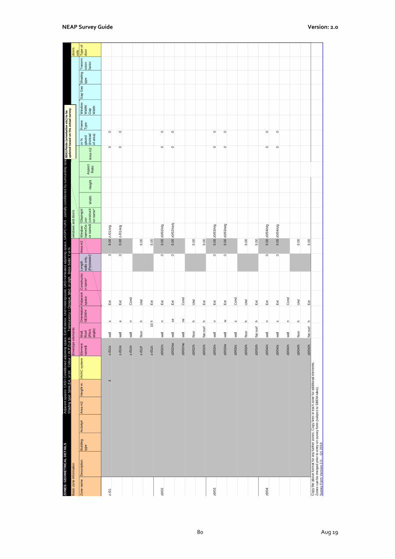
NEAP Survey Guide Version: 2.0
80 Aug 19
ZO
NE
S:
GE
OM
ET
RIC
AL
DE
TA
ILS
Ad
jace
nt sp
ace
s: C
AS
= C
ond
itio
ne
d a
djo
inin
g s
pace
; E
xt=
Exte
rio
r, U
nd
=U
nd
erg
round
, U
AS
=U
nhe
ate
d a
djo
inin
g s
pace
, U
AS
PC
=U
AS
- p
art
ially
co
nd
itio
ne
d b
y s
urr
ound
ing
sp
ace
s
Shad
ing
typ
e: N
one
,Ext, o
r In
t C
olo
ur
= W
,P,D
or
B. T
ranslu
ce
ncy =
Op
aq
ue
, M
ed
, o
r H
igh. B
rise
-So
lei: Y
or
N
Basic
zo
ne
info
rmatio
nE
nve
lop
e e
lem
ents
win
do
ws a
nd
do
ors
win
do
w o
nly
do
ors
only
Zo
ne
nam
eD
escrip
tio
nB
uild
ing
typ
e
Activity#
Are
a m
2H
eig
ht m
HV
AC
syste
mE
lem
ent
nam
e$
Wall,
Ro
of
(Pitch
ang
le)
Orie
nta
tio
n
NE
SW
H
Ad
jace
nt
sp
ace
Co
nstr
uctio
n n
am
e*
Le
ng
th
walls
only
,
(Pe
rim
ete
r)
Are
a m
2W
ind
ow
nam
e/D
o
or
nam
e$
Gla
zin
g/d
oo
r
co
nstr
ucti
on n
am
e*
Wid
thH
eig
ht
Asp
ect
Ratio
Are
a m
2
or
%
gla
ze
d
(inste
ad
of
are
a)
Fra
me
Typ
e
Win
do
w
Wid
th/
Gap
Wid
th
Gap
Gas
Shad
ing
typ
e
Tra
nsm
i
ssio
n
facto
r
Typ
e o
f
do
or
z-/
01
3z-/
01
/sw
all
sE
xt
3
9.0
0z-/
01
/s/g
00
z-/
01
/ew
all
eE
xt
0
0.0
0z-/
01
/e/g
00
z-/
01
/nw
all
nC
ond
z-/
01
/fflo
or
hU
nd
0
.00
z-/
01
/c1
0h
Ext
0
.00
z0
/02
z0
/02
/nw
all
nE
xt
0
0.0
0z0
/02
/n/g
00
z0
/02
/se
wall
se
Ext
0
0.0
0z0
/02
/se
/g
0
0
z0
/02
/ne
wall
ne
Co
nd
z0
/02
/hflo
or
hU
nd
0
.00
z0
/02
/hflat ro
of
hE
xt
0
.00
z0
/03
z0
/03
/nw
all
nE
xt
0
0.0
0z0
/03
/n/g
00
z0
/03
/ww
all
wE
xt
0
0.0
0z0
/03
/w/g
00
z0
/03
/sw
all
sC
ond
z0
/03
/hflo
or
hU
nd
0
.00
z0
/03
/hflat ro
of
hE
xt
0
.00
z0
/04
z0
/04
/nw
all
nE
xt
0
0.0
0z0
/04
/n/g
00
z0
/04
/sw
all
sE
xt
0
0.0
0z0
/04
/s/g
00
z0
/04
/nw
all
nC
ond
z0
/04
/hflo
or
hU
nd
0
.00
z0
/04
/hflat ro
of
hE
xt
0
.00
Co
py the
ab
ove
fo
rmat fo
r any f
urt
he
r zo
ne
s; C
op
y lin
es in e
ach z
one
fo
r ad
ditio
nal e
lem
ents
.
Zo
ne
s c
an b
e m
erg
ed
prio
r to
entr
y o
n s
urv
ey f
orm
(sub
ject to
SB
EM
rule
s).
Surv
ey F
orm
Ve
rsio
n 2
.0.....Q
1 2
01
9
SE
AI:
Fie
lds (
ori
en
tati
on
etc
) to
be
up
da
ted
ba
se
d o
n t
he
actu
al
su
rve
y.

NEAP Survey Guide Version: 2.0
81 Aug 19
Appendix 2: Zoning Examples
A2.1 Zoning example Assessors must adhere to the zoning convention as set out in Section 3.3 in How to use iSBEMie (Volume 1) which may help reduce the amount of time and measurement required. The following is an example office building:
Zoning the building by using the convention set out in How to use iSBEMie (Volume 1) can help reduce the number of measurements that need to be taken. The office building can be zoned as follows:

NEAP Survey Guide Version: 2.0
82 Aug 19
It is important to note that internal envelopes between merged zones with thermal mass must be included
within the model. The m values determine how the building retains and emits heat, and hence they must be defined in iSBEMie. You can sum the areas of two or more internal walls (between merged zones) with the same construction, adjoining condition and orientation and enter them as one envelope (assigned to the zone resulting from the merging). If the internal walls are partitions of light construction and very small thermal mass, then they should not cause any significant effects on the calculation.
A2.2 Cold Stores The process load of a walk-in fridges or freezers should not be included in the iSBEMie analysis. The zone types in the previous version of the software, cold or chilled stores, are no longer included as an activity types in iSBEMie. To enter a cold or a chilled store, select activity type “Warehouse storage” or “24x7 Warehouse storage” under the building type “Storage or Distribution”. The “refrigeration aspect” for this space is a process load since it is designed/provided for the goods and not for the thermal comfort of the occupants in the space and is, therefore, outside the scope of the energy uses which can be accessed via iSBEMie. As such, this zone should be defined as a “Zone without HVAC system” in the iSBEMie model. Furthermore for conditioned spaces which surround this zone, the envelopes which are adjacent to this zone should be defined as adjacent to a “Conditioned adjoining space” so that no heat loss is calculated by the software from the surrounding zones through them since the envelopes of walk-in fridges are usually very well-insulated.

NEAP Survey Guide Version: 2.0
83 Aug 19
Note spaces which accommodate a considerable number of fridges/ freezers, such as in a supermarket or food hall are modelled in iSBEMie using activities such as “Small Shop Unit Sales area - chilled”, “Dept Store Sales area - chilled”, or “Retail Warehouse Sales area - chilled” under the building type “Retail and Financial/Professional services”.

NEAP Survey Guide Version: 2.0
84 Aug 19
Appendix 3: List of Activities
Building Types/Activities R
eta
il and F
inancia
l/P
rofe
ssio
nal
serv
ices
Resta
ura
nt
and C
afe
s/D
rin
kin
g
Esta
blis
hm
ents
and H
ot F
ood
Off
ices a
nd W
ork
shop b
usin
esses
Genera
l In
dustr
ial and S
pecia
l
Industr
ial G
roups
Sto
rage a
nd D
istr
ibutio
n
Hote
ls
Resid
entia
l In
stitu
tio
ns –
Hospitals
and C
are
Hom
es
Resid
entia
l In
stitu
tio
ns –
Resid
ential
prim
ary
schools
Resid
entia
l In
stitu
tions –
Univ
ers
itie
s a
nd c
olle
ges
Secure
Resid
en
tia
l In
stitu
tio
ns
Resid
entia
l spaces
Non-r
esid
entia
l In
stitu
tio
ns –
Com
munity/D
ay C
ente
r
Non-r
esid
entia
l In
stitu
tio
ns –
Lib
rarie
s M
useum
s a
nd G
alle
rie
s
Non-r
esid
entia
l In
stitu
tio
ns –
P
rim
ary
Educatio
n
Non-r
esid
entia
l In
stitu
tio
ns –
Prim
ary
Health C
are
Build
ing
Non-r
esid
entia
l In
stitu
tio
ns –
Law
Court
s
Genera
l A
ssem
bly
and L
eis
ure
plu
s
Nig
ht
Clu
bs a
nd T
heatr
es
Oth
ers
– P
assenger
Te
rmin
als
Oth
ers
– E
me
rgency s
erv
ices
Oth
ers
– M
iscella
neous 2
4hr
activitie
s
Oth
ers
– C
ar
Park
s 2
4 h
rs
Oth
ers
– S
tand-a
lone u
tilit
y b
lock
Non-r
esid
entia
l In
stitu
tio
ns –
Post
Prim
ary
Educatio
n
Non-r
esid
entia
l In
stitu
tio
ns –
Resid
entia
l P
ost-
prim
ary
schools
12hr Specialist Treatment Area X
24hrs Consulting/treatment areas
X
24x7 Bedroom Unit X
24x7 Circulation area (corridors and stairways)
X
24x7 Generic Office Area X X
24x7 Reception X
24x7 Toilet X
24x7 Warehouse storage X
Assembly areas / halls X X
Auditoria X
Bathroom X X X X X X
Bedroom X X X
Bedroom Only X
Bedroom Unit X
Carpark X X X

NEAP Survey Guide Version: 2.0
85 Aug 19
Building Types/Activities R
eta
il and F
inancia
l/P
rofe
ssio
nal
serv
ices
Resta
ura
nt
and C
afe
s/D
rin
kin
g
Esta
blis
hm
ents
and H
ot F
ood
Off
ices a
nd W
ork
shop b
usin
esses
Genera
l In
dustr
ial an
d S
pecia
l
Industr
ial G
roups
Sto
rage a
nd D
istr
ibutio
n
Hote
ls
Resid
entia
l In
stitu
tio
ns –
Hospitals
and C
are
Hom
es
Resid
entia
l In
stitu
tio
ns –
Resid
ential
prim
ary
schools
Resid
entia
l In
stitu
tions –
Univ
ers
itie
s a
nd c
olle
ges
Secure
Resid
en
tia
l In
stitu
tio
ns
Resid
entia
l spaces
Non-r
esid
entia
l In
stitu
tio
ns –
Com
munity/D
ay C
ente
r
Non-r
esid
entia
l In
stitu
tio
ns –
Lib
rarie
s M
useum
s a
nd G
alle
rie
s
Non-r
esid
entia
l In
stitu
tio
ns –
P
rim
ary
Educatio
n
Non-r
esid
entia
l In
stitu
tio
ns –
Prim
ary
Health C
are
Build
ing
Non-r
esid
entia
l In
stitu
tio
ns –
Law
Court
s
Genera
l A
ssem
bly
and L
eis
ure
plu
s
Nig
ht
Clu
bs a
nd T
heatr
es
Oth
ers
– P
assenger
Te
rmin
als
Oth
ers
– E
me
rgency s
erv
ices
Oth
ers
– M
iscella
neous 2
4hr
activitie
s
Oth
ers
– C
ar
Park
s 2
4 h
rs
Oth
ers
– S
tand
-alo
ne u
tilit
y b
lock
Non-r
esid
entia
l In
stitu
tio
ns –
Post
Prim
ary
Educatio
n
Non-r
esid
entia
l In
stitu
tio
ns –
Resid
entia
l P
ost-
prim
ary
schools
Cell (police/prison) X X X
Changing facilities with showers X X X X X X X X X X X X
Circulation area (corridors and stairways)
X X X X X X X X X X X X X
Circulation area (corridors and stairways) – non-public
X X X X X
Circulation area (corridors and stairways) – non-public/restricted
X
Classroom X X X
Common circulation areas X
Computer lab X X X
Data Centre X
Dept Store Sales area - chilled X
Dept Store Sales area - electrical
X
Dept Store Sales area - general X
Diagnostic Imaging X
Display and public areas X
Display window X
Domestic Bathroom X
Domestic Bedroom X

NEAP Survey Guide Version: 2.0
86 Aug 19
Building Types/Activities R
eta
il and F
inancia
l/P
rofe
ssio
nal
serv
ices
Resta
ura
nt
and C
afe
s/D
rin
kin
g
Esta
blis
hm
ents
and H
ot F
ood
Off
ices a
nd W
ork
shop b
usin
esses
Genera
l In
dustr
ial an
d S
pecia
l
Industr
ial G
roups
Sto
rage a
nd D
istr
ibutio
n
Hote
ls
Resid
entia
l In
stitu
tio
ns –
Hospitals
and C
are
Hom
es
Resid
entia
l In
stitu
tio
ns –
Resid
ential
prim
ary
schools
Resid
entia
l In
stitu
tions –
Univ
ers
itie
s a
nd c
olle
ges
Secure
Resid
en
tia
l In
stitu
tio
ns
Resid
entia
l spaces
Non-r
esid
entia
l In
stitu
tio
ns –
Com
munity/D
ay C
ente
r
Non-r
esid
entia
l In
stitu
tio
ns –
Lib
rarie
s M
useum
s a
nd G
alle
rie
s
Non-r
esid
entia
l In
stitu
tio
ns –
P
rim
ary
Educatio
n
Non-r
esid
entia
l In
stitu
tio
ns –
Prim
ary
Health C
are
Build
ing
Non-r
esid
entia
l In
stitu
tio
ns –
Law
Court
s
Genera
l A
ssem
bly
and L
eis
ure
plu
s
Nig
ht
Clu
bs a
nd T
heatr
es
Oth
ers
– P
assenger
Te
rmin
als
Oth
ers
– E
me
rgency s
erv
ices
Oth
ers
– M
iscella
neous 2
4hr
activitie
s
Oth
ers
– C
ar
Park
s 2
4 h
rs
Oth
ers
– S
tand
-alo
ne u
tilit
y b
lock
Non-r
esid
entia
l In
stitu
tio
ns –
Post
Prim
ary
Educatio
n
Non-r
esid
entia
l In
stitu
tio
ns –
Resid
entia
l P
ost-
prim
ary
schools
Domestic Circulation X
Domestic Dining room X
Domestic Kitchen X
Domestic Lounge X
Domestic Toilet X
Dry sports hall X X X X X X X X
Eating/drinking area X X X X X X X X X X X X X X X X X
En suite bedroom X
Fitness studio X
Fitness suite/gym X X X X X X
Food preparation area X X X X X X X X X X X X X X X X X
Generic Check-in areas X
Generic Office Area X X X X X X X X X X X X
Generic Ward X
Hall/lecture theatre/assembly area
X X X X X X X X
Heavy Plant Room X
Hydrotherapy pool hall X
Ice rink X

NEAP Survey Guide Version: 2.0
87 Aug 19
Building Types/Activities R
eta
il and F
inancia
l/P
rofe
ssio
nal
serv
ices
Resta
ura
nt
and C
afe
s/D
rin
kin
g
Esta
blis
hm
ents
and H
ot F
ood
Off
ices a
nd W
ork
shop b
usin
esses
Genera
l In
dustr
ial an
d S
pecia
l
Industr
ial G
roups
Sto
rage a
nd D
istr
ibutio
n
Hote
ls
Resid
entia
l In
stitu
tio
ns –
Hospitals
and C
are
Hom
es
Resid
entia
l In
stitu
tio
ns –
Resid
ential
prim
ary
schools
Resid
entia
l In
stitu
tions –
Univ
ers
itie
s a
nd c
olle
ges
Secure
Resid
en
tia
l In
stitu
tio
ns
Resid
entia
l spaces
Non-r
esid
entia
l In
stitu
tio
ns –
Com
munity/D
ay C
ente
r
Non-r
esid
entia
l In
stitu
tio
ns –
Lib
rarie
s M
useum
s a
nd G
alle
rie
s
Non-r
esid
entia
l In
stitu
tio
ns –
P
rim
ary
Educatio
n
Non-r
esid
entia
l In
stitu
tio
ns –
Prim
ary
Health C
are
Build
ing
Non-r
esid
entia
l In
stitu
tio
ns –
Law
Court
s
Genera
l A
ssem
bly
and L
eis
ure
plu
s
Nig
ht
Clu
bs a
nd T
heatr
es
Oth
ers
– P
assenger
Te
rmin
als
Oth
ers
– E
me
rgency s
erv
ices
Oth
ers
– M
iscella
neous 2
4hr
activitie
s
Oth
ers
– C
ar
Park
s 2
4 h
rs
Oth
ers
– S
tand
-alo
ne u
tilit
y b
lock
Non-r
esid
entia
l In
stitu
tio
ns –
Post
Prim
ary
Educatio
n
Non-r
esid
entia
l In
stitu
tio
ns –
Resid
entia
l P
ost-
prim
ary
schools
Industrial process area X X
Laboratory X X X X X X
Laundry X X X X X X X
Light Plant Room X X X X X X X X X X X X X X X X X X X
Lounges X
Offices and consulting areas X X X X X X X
Operating theatre X
Performance area (stage) X X
Physiotherapy studio X
Post Mortem facility X
Public circulation areas X X
Reception X X X X X X X X X X X X X X X X
Residents common rooms X X
Residents kitchen X
Retail Warehouse Sales area - chilled
X
Retail Warehouse Sales area - electrical
X
Retail Warehouse Sales area - general
X
Sales area - general X

NEAP Survey Guide Version: 2.0
88 Aug 19
Building Types/Activities R
eta
il and F
inancia
l/P
rofe
ssio
nal
serv
ices
Resta
ura
nt
and C
afe
s/D
rin
kin
g
Esta
blis
hm
ents
and H
ot F
ood
Off
ices a
nd W
ork
shop b
usin
esses
Genera
l In
dustr
ial an
d S
pecia
l
Industr
ial G
roups
Sto
rage a
nd D
istr
ibutio
n
Hote
ls
Resid
entia
l In
stitu
tio
ns –
Hospitals
and C
are
Hom
es
Resid
entia
l In
stitu
tio
ns –
Resid
ential
prim
ary
schools
Resid
entia
l In
stitu
tions –
Univ
ers
itie
s a
nd c
olle
ges
Secure
Resid
en
tia
l In
stitu
tio
ns
Resid
entia
l spaces
Non-r
esid
entia
l In
stitu
tio
ns –
Com
munity/D
ay C
ente
r
Non-r
esid
entia
l In
stitu
tio
ns –
Lib
rarie
s M
useum
s a
nd G
alle
rie
s
Non-r
esid
entia
l In
stitu
tio
ns –
P
rim
ary
Educatio
n
Non-r
esid
entia
l In
stitu
tio
ns –
Prim
ary
Health C
are
Build
ing
Non-r
esid
entia
l In
stitu
tio
ns –
Law
Court
s
Genera
l A
ssem
bly
and L
eis
ure
plu
s
Nig
ht
Clu
bs a
nd T
heatr
es
Oth
ers
– P
assenger
Te
rmin
als
Oth
ers
– E
me
rgency s
erv
ices
Oth
ers
– M
iscella
neous 2
4hr
activitie
s
Oth
ers
– C
ar
Park
s 2
4 h
rs
Oth
ers
– S
tand
-alo
ne u
tilit
y b
lock
Non-r
esid
entia
l In
stitu
tio
ns –
Post
Prim
ary
Educatio
n
Non-r
esid
entia
l In
stitu
tio
ns –
Resid
entia
l P
ost-
prim
ary
schools
Server Room X
Small Shop Unit Sales area - chilled
X
Small Shop Unit Sales area - electrical
X
Small Shop Unit Sales area - general
X
Specialist Care Ward X
Store Room X X X X X X X X X X X X X X X X X X
Swimming Pool X X X X X
Teaching Areas X X X X
Teaching Areas DoES TGD033 2018
X X X X
Toilet X X X X X X X X X X X X X X X X X X X
Waiting Rooms X
Warehouse storage X X
Workshop – small scale X X X X X X X X

NEAP Survey Guide Version: 2.0
89 Aug 19
Appendix 4: Default Data
This section outlines defaults to be used for non-domestic BERs in the absence of evidence supporting non-default data. Actual data must be used where acceptable evidence is available.
A4.1 Project Database
The Age of Building/ Year of Construction is used to identify the appropriate default U-values for construction elements based on the relevant building regulations.
Note on use of defaults:
1) Buildings constructed prior to the introduction of Building Regulations in 1991 were not required to have
insulation; therefore, the Assessor must demonstrate that insulation is present when selecting “1974 – 1990”
options for external elements. “1974 - 1990” assumes a certain amount of insulation is present. If unable to
demonstrate that insulation is present in “1974 – 1990”” buildings, “No date – Uninsulated” must be used for
external elements from “Help with Inference procedures”.
2) Buildings constructed after the introduction of Building Regulations in 1991 were required to have insulation,
therefore select relevant building regulations for external elements except where the element is known to be
uninsulated. In this case, select “No date – Uninsulated” from “Help with Inference procedures”.
3) For internal elements (walls, floors or ceilings), irrespective of the adjoining condition, select “No date –
Uninsulated” irrespective of the age of the building, unless able to demonstrate that insulation is present. In
this case, calculate the U-value by adding the insulation resistance to the default U value for the element
without insulation.
4) For glazing, the survey process provides information on window area, glazing type, age, frame type and
orientation. Select from “Import one from the library” within iSBEMie software. For the Glazing type assume:
• If unable to determine whether double glazing is Low “E” or not, assume that double glazing installed
before 2004 is not Low “E” and during or after 2004 is Low “E”.
• Assume that double or triple glazing is air filled unless documentary evidence is provided to
substantiate an alternate.
• The gap between double and triple glazing panes must be assumed as 6mm unless measured as
otherwise (accounting for pane thickness of 4mm where necessary).
In all cases, the non-default U-values can be calculated using full details where available. For example, for
opaque elements thicknesses and thermal properties are known for all the layers and for glazed elements
manufacturers declaration forms are available in compliance with relevant standards.
iSBEMie Software Tab: “Project Database ”
Year of Construction Relevant Building Regulations and selecting defaults.
Pre 1994 (external elements)
Opaque Element
“No date – Uninsulated” –is selected unless the element is proven to be insulated.
1974 - 1990–where element is proven to be insulated.
Glazing:
Glazing – As per Note 4
Frame Age – “Pre 1991”

NEAP Survey Guide Version: 2.0
90 Aug 19
1994 to 1999 (external elements)
Opaque Element:
1991 Building Regulations or,
“No date – Uninsulated” – where element is known to be uninsulated.
Glazing:
Glazing – As per Note 4
Frame Age - 1991 & 1997 Part L
2000 to 2007 (external elements)
Opaque Element:
1997 Building Regulations or,
“No date – Uninsulated” – where element is known to be uninsulated.
Glazing:
Glazing – As per Note 4
Frame Age - 1991 & 1997 Part L
2008 to 2009 (external elements)
Opaque Element:
2006 Building Regulations or,
“No date – Uninsulated” – where element is known to be uninsulated.
Glazing:
Glazing – As per Note 4
Frame Age - 2006 & 2008 Part L
Post 2010 to 2018 (external elements)
Opaque Element:
2008 Building Regulations or,
“No date – Uninsulated” – where element is known to be uninsulated.
Glazing:
Glazing – As per Note 4
Frame Age - 2006 & 2008 Part L
Post 2019 (external elements)
Opaque Element:
2017 Building Regulations or,
“No date – Uninsulated” – where element is known to be uninsulated.
Glazing:
Glazing – As per Note 4
Frame Age - 2017 Part L
Internal Elements Opaque Element:
“No date – Uninsulated” – unless proven to be insulated.
Glazing:
Not included in Assessment
The following examples demonstrate use of the methodology in determining the construction type for various
elements:
Example 1: Roof
The building was constructed in 1975 with a precast concrete flat roof. Following the guidance above the assessor uses the “Help with Inference procedures” to select the following roof:
“No date, uninsulated” is selected because the building was constructed prior to 1994 and there is no evidence of insulation.
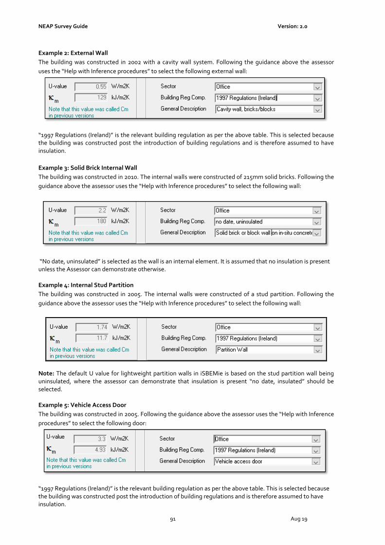
NEAP Survey Guide Version: 2.0
91 Aug 19
Example 2: External Wall
The building was constructed in 2002 with a cavity wall system. Following the guidance above the assessor
uses the “Help with Inference procedures” to select the following external wall:
“1997 Regulations (Ireland)” is the relevant building regulation as per the above table. This is selected because the building was constructed post the introduction of building regulations and is therefore assumed to have insulation.
Example 3: Solid Brick Internal Wall
The building was constructed in 2010. The internal walls were constructed of 215mm solid bricks. Following the
guidance above the assessor uses the “Help with Inference procedures” to select the following wall:
“No date, uninsulated” is selected as the wall is an internal element. It is assumed that no insulation is present unless the Assessor can demonstrate otherwise. Example 4: Internal Stud Partition
The building was constructed in 2005. The internal walls were constructed of a stud partition. Following the
guidance above the assessor uses the “Help with Inference procedures” to select the following wall:
Note: The default U value for lightweight partition walls in iSBEMie is based on the stud partition wall being uninsulated, where the assessor can demonstrate that insulation is present “no date, insulated” should be selected. Example 5: Vehicle Access Door
The building was constructed in 2005. Following the guidance above the assessor uses the “Help with Inference
procedures” to select the following door:
“1997 Regulations (Ireland)” is the relevant building regulation as per the above table. This is selected because the building was constructed post the introduction of building regulations and is therefore assumed to have insulation.

NEAP Survey Guide Version: 2.0
92 Aug 19
A4.2 HVAC System Defaults In some zones, a default HVAC system must be specified. Further Guidance is given in Appendix 7 through the use of flow charts in helping identify the use of default HVAC systems. Default HVAC systems are applied to zones meeting the following criteria:
• There is no fixed heating installed;
• There are floor and ceiling finishes, lighting, and ventilation as appropriate;
• The Activity Type requires conditioning;
• There is no proposed design available specifying a HVAC system
• Not considered transient or indirectly conditioned spaces.
Section 3.4.3 of How to use iSBEMie (Volume 2)states “If a zone is defined as having no heating or cooling, i.e., assigned to ‘Zones without HVAC system’, but the activity type selected for the zone is one which typically requires conditioning (according to the Activity Database), a red exclamation mark “!”appears next to this parameter as a warning to the user, in case this was done in error.“ When assuming a default HVAC system following the guidance above and Appendix 7, use the following table:
iSBEMie Software Tab: “HVAC”
Data Entry Item Default Value
No evidence of a HVAC present
The default HVAC systems for buildings are as follows:
1. 'Heating only - Electric resistance’ - Assumed to be an electric central heating system
with warm air distribution. If you do not know the heating method, you should select
electric resistance heating as your default. Selected when no non-electrical fuels are
present.
2. “Heating only - Other systems’ - Assumed to be wet radiator system, heat generated
by fuel combustion. This is applied where the building also has a fuel source other
than electricity installed.
3. ‘Heating and mechanical cooling’ - Assumed to be constant volume air system with
terminal reheat and fixed fresh air. This is the assumed HVAC system in the absence
of other information for conditioned spaces.
4. If no HVAC system serves a zone (ie an unconditioned zone in iSBEMie) select “Zone
without HVAC system”. This is only in the case where it has been justified that a
HVAC system is not required in the zone in the NEAP assessment.
For details Refer to Section 3.4.3 of How to use iSBEMie (Volume 2)
The following table outlines when various default HVAC systems apply following the guidance above:

NEAP Survey Guide Version: 2.0
93 Aug 19
Default HVAC
System
Building Condition Zone Conditions
Heating only -
Electric resistance
No alternate (e.g. gas/oil)
fuel present in the building.
Electricity may or may not
be connected to the
building.
• Zone Activity requires heating (as highlighted by the red
exclamation mark in iSBEMie), for example:
Offices, Meeting Rooms, Laboratory, Consulting
Room, Sales Area, Performance Area, Classroom
Does not include unheated transient or indirectly
conditioned spaces or spaces heated by a process load.
• While the zone activity requires heating, the zone is also
capable of being naturally ventilated and therefore there
is no requirement for cooling. The zone also lends itself
to meeting CIBSE Guide A and the Building Regulations
for naturally ventilated spaces. The CIBSE Guide A
Section 1.4.2.5 and Building Regulation requires that in
the absence of mechanical cooling or mechanical
ventilation. The zone would be expected to achieve
adequate natural ventilation following Building
Regulation/ CIBSE requirements under the following
circumstances:
• Internal load is not excessive, and
• Space can be naturally ventilated for example:
• Zones not deeper than 7m for single side
ventilation and 14m for cross ventilation
• Sufficient natural ventilation openings e.g.
openable windows, doors (approximately 5%
of floor area)

NEAP Survey Guide Version: 2.0
94 Aug 19
Default HVAC
System
Building Condition Zone Conditions
Heating only -
Other systems
Alternate fuel present in the
building, for example:
• Natural Gas pipework
connected to building,
whether meter evident
or not.
• Oil Tank Present and
connected to building
• LPG Tank Present and
connected to building
• Solid Fuel Store
Present appropriate
size to heat building.
• Zone Activity requires heating (as highlighted by the red
exclamation mark in iSBEMie), for example:
Offices, Meeting Rooms, Laboratory, Consulting
Room, Sales Area, Performance Area, Classroom
Does not include unheated transient or indirectly
conditioned spaces or spaces heated by a process load.
• While the zone activity requires heating, the zone is also
capable of being naturally ventilated and therefore there
is no requirement for cooling.
The zone also lends itself to meeting CIBSE Guide A and
the Building Regulations for naturally ventilated spaces.
The CIBSE Guide A Section 1.4.2.5 and Building
Regulation require that in the absence of mechanical
cooling or mechanical ventilation. The zone would be
expected to achieve adequate natural ventilation
following the Building Regulation/ CIBSE requirements
under the following circumstances:
• Internal load is not excessive, and
• Space can be naturally ventilated for example:
• Zones not deeper than 7m for single side
ventilation and 14m for cross ventilation
• Sufficient natural ventilation openings e.g.
openable windows, doors (approximately 5%
of floor area)

NEAP Survey Guide Version: 2.0
95 Aug 19
Default HVAC
System
Building Condition Zone Conditions
Heating and
mechanical
cooling
Alternate fuel present in the
building and where cooling
is required, for example:
• Natural Gas pipework
connected to building,
whether meter evident
or not.
• Oil Tank Present and
connected to building
• LPG Tank Present and
connected to building
• Solid Fuel Store
Present appropriate
size to heat building.
Where no alternate fuel is
present in the building, but
it is proven that cooling is
required, “Natural Gas” is
selected as the heating fuel.
Currently electricity is not
available as a heating fuel
for the default system,
“Natural Gas” is selected as
it is the heating fuel used in
the notional building.
Grid supplied electricity is
selected for cooling.
• Zone Activity requires heating (as highlighted by the red
exclamation mark in iSBEMie), for example:
Offices, Meeting Rooms, Laboratory, Consulting
Room, Sales Area, Performance Area, Classroom
Does not include unheated transient or indirectly
conditioned spaces or spaces heated by a process load.
• Zone also requires cooling and it is not possible to
naturally ventilate, for example:
Offices, Meeting Rooms, Laboratory, Consulting
Room, Sales Area, Performance Area, Classroom
Does not include unheated transient, indirectly heated spaces
or spaces heated by a process load.
Transient zones Some unheated zones have a transient/ passing occupancy such as toilets. For transient zones, where “Zones without HVAC system” is applicable, it is acceptable for the red exclamation mark”!” to appear. There are further details on transient spaces refer to Appendix 7 and 8 of this survey guide. Indirectly conditioned zones As outlined in Section 3.5.9 of How to use iSBEMie (Volume 2), zones which are not serviced by a HVAC system, i.e. have no direct supply of heating or cooling, but are likely to be indirectly conditioned by the surrounding areas due to the high level of interaction with those spaces (allowing the heated air to move freely from the directly conditioned spaces to the indirectly conditioned ones or heat to escape through uninsulated envelopes from directly conditioned spaces to unconditioned spaces), they must be considered heated or conditioned (indirectly) by the same HVAC system that supplies the most important surrounding area”. Refer to Appendix 8 of this survey guide for further guidance. Zones with Air Curtains or Inadequate HVAC Air curtains are usually designed to prevent cold air entering a space rather than to condition a space.
• Where the air curtain is the only source of heating in the zone, if the output of the heater is less than 10 W/m2, the zone is deemed as unconditioned and “Zone without HVAC System” is assigned. If the

NEAP Survey Guide Version: 2.0
96 Aug 19
output of the heater is greater than 10 w/m2, the zone is deemed to be conditioned and HVAC system is assigned.
• Where the air curtain is one of the sources of heating in the zone, it is entered as a Bivalent system.
Occasionally BER Assessors may encounter the use of local heating, often radiant based, which is designed to heat an occupant within an unconditioned work area. If the output of the heater within the area is less than 10 W/m2, the zone can be deemed as unconditioned and “Zones without HVAC system” is assigned.
A4.3 HWS System
iSBEMie Software Tab: “HWS”
Data Entry Item Default Value
No evidence of a Hot Water System present
Where no evidence of Storage/ Secondary Circulation Losses Present:
“Instantaneous Hot Water only” should be selected with a fuel type selected based on
fuel supplied to the unit, “Grid Supplied Electricity” should be selected where oil/gas not
present.
HWS System Storage/ Secondary Circulation Losses: Not present
Where evidence of Storage/ Secondary Circulation Losses Present:
Where a fuel (oil/gas) is supplied to the building, the HWS System:
“Dedicated Hot Water Boiler” should be selected with a fuel type based on fuel supplied
to unit.
Where oil/gas is not supplied to the building, the HWS System:
“Stand-alone water heater” should be selected with a fuel type based on “Grid Supplied
Electricity”
HWS System Storage/ Secondary Circulation Losses: Based on defaults where evidence
not available.
The Section 3.5.9 of How to use iSBEMie (Volume 2) states that “Depending on the
activity and building type selected for the zone, a standard hot water demand is
assumed. For example, there is a demand assumed to arise from the occupants of an
office for activities such as washing hands and washing up cups. This demand is
associated with the office rather than the toilet or tea room.”
Evidence of a Hot Water System present but cannot be accessed
The BER Assessor is satisfied that there is a hot water generator serving the building, but
it cannot be accessed because it is behind fitted furniture or is in a locked or otherwise
inaccessible area.
Follow the guidance above for “No evidence of a Hot Water System present”
Hot Water Storage system insulation if not accessible
The insulation thickness is based on the age of the storage unit as below: If the age of the storage unit is unknown, it must be assumed that the storage unit is the same age as the building. CE marked heaters may be assumed to have at least 25mm of factory insulation.
Pre 1994: No Insulation
1994 to 1999: 25mm Factory Insulated
Post 1999: 35mm Factory Insulated

NEAP Survey Guide Version: 2.0
97 Aug 19
A4.4 SES System
iSBEMie Software Tab: “SES”
Data Entry Item Default Value
Evidence of solar
collector present but
data unobtainable
If present, the parameters for the calculation are as follows for each unobtainable item:
- panel aperture area 3 m²;
- flat panel, glazed;
- facing South, pitch 30°;
- combined cylinder, solar part one-third of total, or if a combi boiler the cylinder
identified is a dedicated solar cylinder. If combined cylinder is accessible, solar storage
volume is portion below the coil directly above the solar heated coil.
Gross Area obtained
from survey
Aperture Area= Flat Plate Glazed Gross Area x 0.9
Aperture Area= Evacuated Tube Gross Area x 0.72
A4.5 PV System
iSBEMie Software Tab: “PVS”
Data Entry Item Default Value
Evidence of PV
present but data
unobtainable
If present, the parameters for the calculation are as follows for each unobtainable item:
- PV area is roof area for heat loss, times percent of roof area covered by PVs, and if
pitched roof divided by cos (35°) ;
- Type: Amorphous silicon;
- facing South, pitch 30°.
- Unventilated modules
A4.6 Wind Turbine
iSBEMie Software Tab: “Wind generators”
Data Entry Item Default Value
Evidence of Wind
Turbine present but
data unobtainable
If present, the parameters for the calculation are as follows for each unobtainable item:
- Height: Estimate relative to height of building;
- Diameter of turbine: Estimate relative to height of turbine;
- Terrain Type: Urban with average building height > 15m.
A4.7 Shell and Core Buildings
For shell and core buildings not all of the services are installed (especially lighting, mechanical ventilation and
cooling) at the point where the building is sold or let. Buildings (or parts of) that have not previously been sold
or occupied and are let or sold as bare structures, without services at all, will nonetheless require a BER
A “Shell and Core” building or zone would typically be where only the bare structure is in place, internal fittings
such as flooring and ceiling finishes, lighting, heating, cooling or ventilation have yet to be installed. For
example, a retail unit to be fitted out at a later date by a tenant.
As the building (or part of) is being sold or let without being fully completed, the BER will be New Build –
Provisional. For Shell and Core Buildings, the requirement for demonstrating compliance with the building
regulations will be based on the following:
- MPEPC/ MPCPC and RER will be met based on Building Fabric as built, fixed services as
installed and design intent for services yet to be installed.

NEAP Survey Guide Version: 2.0
98 Aug 19
- Once a part of the building has been leased/ sold and fitted out for the first time, a final BER
will need to be published for that part of the building. The building must continue to show
compliance through an average of the EPC/ CPC and RER for the building
For example;
A new building has 5 floors, the landlord area has been fitted out with services, while each of the tenant areas
are being sold/ leased as a shell.
Compliance is demonstrated by the fixed services in the Landlord Area and the design intent for the 5 tenant
areas. The developer plans to lease the tenant areas to 3 tenants.
Tenant 1 acquires floors 4 and 5, once these have been fitted out a final BER must be published for the area
leased by Tenant 1. Compliance is demonstrated by taking the average the EPC/CPC and RER for the building.
The landlord area EPCL, CPCL and RERL is based on Final BER certificate for the Landlord Area
Tenant 1 area EPC1, CPC1 and RER1 is based on Final BER certificate for Tenant 1.
Tenant 2 and 3, have not yet been fitted out so the EPC2 and 3, CPC2 and 3 and RER2 and 3 are based on the
design intent and Provisional BERs.
The BER of a Shell and Core building is based on the following:
Data Entry Item Default Value
Proposed Design Available
Where a proposed mechanical and electrical design is available, the HVAC and lighting
system are based on the mechanical and electrical specifications, schedules and drawings
for the shell and core unit.
For compliance with the 2017 Building Regulations Part L for Building other than
Dwellings, as outlined in section 0.1.1.6 of the technical guidance document, the design
and specification should be compatible with the intended building end use and servicing
strategy. The renewable requirement of the shell and core building should be installed at
an early stage in the construction process to ensure that the building will meet the
renewables provision for the whole building when completed. The renewable installation
should be based on the RER requirement to achieve Part L 2017 compliance and where
full building service installation is not provided until tenant fit-out stage, the RER is
calculated based on the intended use/ uses of the building and the proposed mechanical
and electrical design for the building as a whole.
Landlord
Tenant 1
Tenant 1
Tenant 2
Tenant 2
Tenant 3

NEAP Survey Guide Version: 2.0
99 Aug 19
No Design Available HVAC System: Select default system “Heating and Mechanical Cooling” which is based
on Terminal reheat (constant volume) and air-cooled chiller. For heating the fuel type
should be as available on site, where no alternate fuel is present in the building, “Natural
Gas” is selected as the heating fuel. Currently electricity is not available as a heating fuel
for the default system, “Natural Gas” is selected as it is the heating fuel used in the
notional building.
A HVAC system is assigned to every zone where the activity type selected for the zone is
one which typically requires conditioning (according to the Activity Database), and a red
exclamation mark “!”appears.
HWS System: “Instantaneous Hot Water only” is selected with a fuel type as available on
site, where no alternate fuel is present “Grid Supplied Electricity” should be selected.
HWS System Storage/ Secondary Circulation Losses: Not present.
Lighting: Lighting Parameters Not Available; Lamp Type: Tungsten.
Lighting Controls: Local Manual Switching.
Shell and Core Buildings cannot demonstrate compliance with 2017 Building Regulations
without specification of intended servicing strategy.
As per the Code of Practice, BER Assessors are required to carry out a full building survey where an Existing or New Final BER certificate is being published or where a Provisional Certificate is being produced for a Shell and Core building which is being built. In the case of Shell and Core buildings this may be just verifying that no services are installed along with collecting other data such as dimensions. If there is any material change to the data in the BER assessment such as fabric, services for heating, hot water, mechanical ventilation or air conditioning, the original BER certificate is no longer valid. This applies to all buildings – not just shell and core buildings.
Zone Activity The Assessor should select the most appropriate activity type for the building.
A4.8 Default exhaust rates
When exhaust fans are encountered in existing buildings a BER Assessor will often have no information on the installed flow rate of the extract system. Where fan data plates can be read the information can be used to enter a non-default value. In the absence of such information the following table lists some default exhaust flow rates to be used.
Description iSBEMie activity Assumed extract rate
Small kitchen or kitchenette or tea making facility with a single extractor fan only. Very limited food preparation activities taking place. (When entering as part of single zone with office space, divide ACH by volume of Tea Making and multiply by volume of zone)
Generic Office (was Tea Making)
10 ACH
Domestic’ type kitchen with a single cooker hood extraction unit and limited food preparation activities
Food preparation 15 ACH
Commercial kitchen with multiple cooker hood extraction. Extensive food preparation activities, e.g. kitchen serving restaurant
Food preparation 40 ACH
Toilet Toilet 6 litres /second per WC/Urinal

NEAP Survey Guide Version: 2.0
100 Aug 19
Shower/ Bath Shower/ Bath 15 litres /second per shower/ bath
To convert Air Changes per Hour (ACH) to l/s/m2 for entry to iSBEMie: If Room height = 3.2 m, Extract fan 10ACH
3.2m x 10ACH / 3.6 = 3.67 l/s/m2
A4.9 Display Lighting
iSBEMie Software Tab: “Zones / Display Lighting”
Data Entry Item Default Value
Zones incorporate an
activity whereby
iSBEMie automatically
assumes the presence
of display lighting.
Where zones incorporate an activity whereby iSBEMie automatically assumes the
presence of display lighting, but none is actually present or where the display lighting
uses efficient lamps, the display lighting parameter should to be adjusted.
Where there is no display lighting, the efficiency for iSBEMie is entered based on the
general lighting present in that zone.
Where possible this should be calculated, but as this requires detailed measurements of
the lumen (lm) and circuit watt (cW) this is not usually practical in existing buildings. The
following ‘default’ values are used in the absence of more detailed information:
1. Where the general lighting is not using Tungsten or Tungsten Halogen lamps,
enter that the display lighting uses efficient lamps and enter the lamps luminous
efficacy based on Table 12 of How to use iSBEMie (Volume 2). If there is more
than one type, the lowest applicable value from Table 12 should be used.
2. When the general lighting uses Tungsten or Tungsten Halogen lamps; enter that
the display lighting does not use efficient lamps. In this case, a “Lumens per
circuit wattage” entry is not required.
For the purposes of the lighting calculations in iSBEMie, efficient display lighting is one
with a lamp and ballast efficacy better than 15 lamp-lumens per circuit-Watt. Where
details of Display Lighting are available, the performance in iSBEMie should be updated
to reflect performance. Examples of efficient display lighting lamps include: metal halide,
compact fluorescent, and white SON (high pressure sodium).
For Example A supermarket has T5 Fluorescent - triphosphor-coated - high frequency ballast lighting generally but has a combination of metal halide and compact fluorescent lighting display lights. No further information is available. The zone lighting could be chosen as “T5 Fluorescent - triphosphor-coated - high frequency ballast” and display lighting changed to “Energy efficient lamps”. From Table 12, metal halide lamps have an efficacy of 25 for side-lit zones, whilst compact fluorescent lamps have an efficacy of 22.5 luminaire lumens per circuit Watt. Therefore 22.5 is entered as the display lighting lamp lumen efficacy.
A4.10 Non-Default m Value
A non-default m value (kJ/m2K) is based on the makeup of the construction. As outlined in Section 3.3.1 of
How to use iSBEMie (Volume 2), the m value is calculated as follows:
m value = density (kg/m3) x thickness (m) x specific heat capacity (kJ/(kgK))
Starting from the layer of the construction closest to the space (interior), add the values together until any one
of the following conditions is satisfied:

NEAP Survey Guide Version: 2.0
101 Aug 19
• The sum of the layer thicknesses has reached 0.1m,
• You have reached the mid-point of the construction or
• You have reached an insulating layer (has a conductivity of 0.08 W/mK or less)
Details of the density for common building materials can be obtained from Building Regulation TGD L –
Buildings Other Than Dwellings (Table A1) or from CIBSE Guide A.
Details of specific heat capacity for common building materials can be obtained from CIBSE Guide A or from
the table below:
Material Specific Heat Capacity (J/(kgK))
Clay Brickwork 1000
Concrete Block 1000
Cast Concrete 1000
Aerated Concrete Slab 1000
Concrete Screed 1000
Reinforced Concrete 1000
Mortar 920
External Render 1000
Plaster/ Plasterboard 1000
Natural Slate 840
Clay Tiles 840
Asphalt 920
Felt Bitumen layers 1700
Wood 1700
The following shows an example of how to calculate the m value for an external wall:
The wall consists of the following construction layers:
Layer (Inner to Outside) d (mm) Conductivity
(W/mK)
Density
(kg/m3)
Specific Heat Capacity
(J/(kgK))
Plasterboard 13 0.18 600 1000
Concrete block (dense) 100 1.130 2000 1000
insulation 75 0.040 20 1450
Air Gap 50
Brick outer leaf 105 0.770 1700 1000
As outlined in Section 3.3.1 of How to use iSBEMie (Volume 2), the m value is calculated until the sum of layers
equals 0.1m or an insulating layer is met, in this case the m value is as follows:
600kg/m3 x 0.013m x (1000J/kgK/ 1000J/kJ) = 7.8 kJ/m2K
2000kg/m3 x (0.1 – 0.013†)m x (1000J/kgK/1000J/kJ) = 174 kJ/m2K
m value 181.8 kJ/m2K
† The 0.1m thickness is reached

NEAP Survey Guide Version: 2.0
102 Aug 19
Appendix 5: Sessional Efficiency of Heating, Cooling and Ventilation Systems
Assessors must calculate the seasonal efficiency for various heating and cooling systems in buildings. This
appendix outlines the details of how the seasonal efficiency is calculated for various systems.
A5.1 Boilers
A single boiler’s seasonal efficiency is based on the gross efficiency calculated at 100% load and 30% load.
Under the Ecodesign Directive 813/ 2013, manufacturers are required to publish the efficiency at both loads.
The seasonal efficiency is calculated as follows:
Boiler seasonal efficiency = 0.81 ŋ30% + 0.19 ŋ 100%
Where;
ŋ30% is the gross boiler efficiency measured at 30% load
ŋ 100% is the gross boiler efficiency measured at 100% load
For boilers with an output > 400 kW, the manufacturer’s declared efficiency should be used.
In the case of multiple boiler systems, the seasonal efficiency is calculated using the weighted average of
efficiencies for 3 load conditions:
Multiple Boiler seasonal efficiency = 0.36 ŋ15% + 0.81 ŋ30% + 0.19 ŋ 100%
Where;
Ŋ15% is the gross boiler efficiency measured at 15% load
The following examples demonstrate use of the Compliance Guide in determining seasonal heating efficiency
(boilers)
Example 1: Building with a Condensing Gas Boiler and Standard Gas Boiler. Information from Building Survey: Heating Load: 200kW
Boiler 1 Boiler 2
kW Rating 150kW 150kW
Fuel Type Gas Gas
Stage Lead Lag
Boiler Efficiency based on Gross Calorific Value from accredited data
90% at 100% load 96% at 30% load
82% at 100% load 86% at 30% load
Using the following table, the seasonal efficiency is calculated as follows:
Boiler % efficiency at boiler outputs of
Boiler % output at system outputs of
Boiler % efficiency at system outputs of
Boiler No
Rating kW
100% 30% 15% 30% 100% 15% 30% 100%
1
2
3
System efficiency at part load
Weighting factor 0.36 0.45 0.19
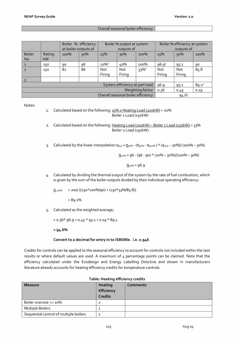
NEAP Survey Guide Version: 2.0
103 Aug 19
Overall seasonal boiler efficiency
Boiler % efficiency at boiler outputs of
Boiler % output at system outputs of
Boiler % efficiency at system outputs of
Boiler No
Rating kW
100% 30% 15% 30% 100% 15% 30% 100%
1 150 90 96 20%1 40% 100% 96.93 95.1 90
2 150 82 86 Not Firing
Not Firing
33%2 Not Firing
Not Firing
85.8
3
System efficiency at part load 96.9 95.1 89.14
Weighting factor 0.36 0.45 0.19
Overall seasonal boiler efficiency 94.65
Notes:
1. Calculated based on the following: 15% x Heating Load (200kW) = 20% Boiler 1 Load (150kW)
2. Calculated based on the following: Heating Load (200kW) – Boiler 1 Load (150kW) = 33% Boiler 2 Load (150kW)
3. Calculated by the linear interpolation ηb,p = η30% - (η30% - η100% ) * (q b,p – 30%)/ (100% – 30%)
η20% = 96 - (96 - 90) * (20% – 30%)/(100% – 30%)
η20% = 96.9
4. Calculated by dividing the thermal output of the system by the rate of fuel combustion, which is given by the sum of the boiler outputs divided by their individual operating efficiency.
η 100% = 200/ ((150*100%/90) + (150*33%/85.8)) = 89.1%
5. Calculated as the weighted average;
= 0.36* 96.9 + 0.45 * 95.1 + 0.19 * 89.1 = 94.6% Convert to a decimal for entry in to iSBEMie. i.e. 0.946
Credits for controls can be applied to the seasonal efficiency to account for controls not included within the test
results or where default values are used. A maximum of 4 percentage points can be claimed. Note that the
efficiency calculated under the Ecodesign and Energy Labelling Directive and shown in manufacturers
literature already accounts for heating efficiency credits for temperature controls.
Table: Heating efficiency credits
Measure Heating
Efficiency
Credits
Comments
Boiler oversize <= 20% 2
Multiple Boilers 1
Sequential control of multiple boilers 1

NEAP Survey Guide Version: 2.0
104 Aug 19
TRV / Temperature Zone Control 1 Evidence required that not included in Test Data
Weather Compensation 1.5 Evidence required that not included in Test Data
Room Thermostat 0.5 Evidence required that not included in Test Data
Optimum Start 1.5 Evidence required that not included in Test Data
Optimum Stop 0.5 Evidence required that not included in Test Data
Optimum Start/ Stop 2 Evidence required that not included in Test Data
Full Zoned Time Control 1 Evidence required that not included in Test Data
Full building management system 4 Evidence required that not included in Test Data
Decentralised heating system 1
Example 2: Gas Boiler and Controls. Information from Building Survey: Heating Load: 200kW
Boiler 1
kW Rating 300kW
Fuel Type Gas
Stage Lead
Seasonal Boiler Efficiency based on Gross Calorific Value
82%
Temperature Controls TRVs on all radiators
Optimised Start/Stop
Using Table above the seasonal efficiency is calculated as follows:
Heating Efficiency Credits
Boiler Efficiency 82%
System uses TRVs to ensure full building temperature control 1
System uses Optimised Start/Stop to achieve specified conditions during occupancy period
2
Total Credits 3
Effective boiler seasonal efficiency: = Boiler Efficiency + maximum of 4 heating efficiency credits = 82% + 3%
= 85%
A5.2 Heat Pump Guidance
The Heat Pump Methodology for Non-Domestic Buildings is currently under development.
The following guidance must be followed for demonstrating compliance until such time as the methodology is
published.
For Space Heating:

NEAP Survey Guide Version: 2.0
105 Aug 19
Where a heat pump make/ model is compliant with the Ecodesign and Energy Labelling Directive or has EN
14825 accredited test data, the “Seasonal Space Heating Efficiency” is taken for High Temperature (55oC).
The “Seasonal Space Heating Efficiency” taken directly from the Ecodesign declaration (%) is converted by
multiplying by 2.5 and divided by 100 for entry into iSBEMie. For example, a Heat Pump with “Seasonal Space
Heating Efficiency” of 120% is converted and entered into iSBEMie as follows: 120 x 2.5 / 100 = 3.
Note: The factor of 2.5 is based on Ecidesign declared efficiency being based on primary energy of electricity
using an EU wide standard primary energy factor of 2.5.
Where an assessor wishes to use the “Seasonal Space Heating Efficiency” at Low Temperature (35oC), they
must provide sufficient documentary evidence from the designer to demonstrate design flow temperature.
Where there is insufficient documentary evidence available to support the Seasonal Space Heating Efficiency a
default value must be used.
For Hot Water:
Where a Heat Pump is used for water heating, the assessor must select “Heat Pump” as the generator type and
cannot select “Same as HVAC” irrespective of the presence or not of a heat pump in the HVAC system.
Where a heat pump make/model is compliant with the Ecodesign and Energy Labeling Directive or has
EN16147 test data, the “Water Heating Energy Efficiency” is taken. As with the Space Heating this needs to be
converted for entry into iSBEMie.
Where there is insufficient documentary evidence available to support the Water Heating Energy Efficiency a
default value must be used.
A5.3 Cooling Seasonal Efficiency
The seasonal efficiency is based on the part load energy efficiency ratios EER measured at 100%, 75%,50% and
25% operating conditions. Under the Ecodesign Directive, manufacturers are required to publish the part load
EERs. The seasonal efficiency is calculated as follows:
SEER = a(EER100% ) + b(EER75%) + c(EER50%) + d(EER25%)
Where;
EER x% is the part load energy efficiency ratio at 100%, 75%, 50% and 25% operating conditions.
a, b, c and d are the load profile weightings.
Sample load profiles:
a b c d
Unknown load profile 0.25 0.25 0.25 0.25
Office load profile 0.03 0.33 0.41 0.23
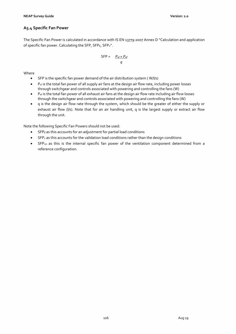
NEAP Survey Guide Version: 2.0
106 Aug 19
A5.4 Specific Fan Power
The Specific Fan Power is calculated in accordance with IS EN 13779:2007 Annex D “Calculation and application
of specific fan power. Calculating the SFP, SFPE, SFPV”.
SFP = Psf + Pef
q
Where
• SFP is the specific fan power demand of the air distribution system ( W/l/s)
• Psf is the total fan power of all supply air fans at the design air flow rate, including power losses through switchgear and controls associated with powering and controlling the fans (W)
• Pef is the total fan power of all exhaust air fans at the design air flow rate including air flow losses through the switchgear and controls associated with powering and controlling the fans (W)
• q is the design air flow rate through the system, which should be the greater of either the supply or
exhaust air flow (l/s). Note that for an air handling unit, q is the largest supply or extract air flow
through the unit.
Note the following Specific Fan Powers should not be used:
• SFPE as this accounts for an adjustment for partial load conditions
• SFPv as this accounts for the validation load conditions rather than the design conditions
• SFPint as this is the internal specific fan power of the ventilation component determined from a
reference configuration.

NEAP Survey Guide Version: 2.0
107 Aug 19
Appendix 6: Determining Zone Heights and U-Values
Zone Height and Element Areas
• For ground and intermediate floors, the zone height is from top of floor slab to top of floor slab.
• For top floor the zone height is from top of floor slab to soffit/ underside of roof slab
• For the purpose of zone height and surrounding wall areas, suspended ceilings and raised floors are ignored.
Example 6.1
For top floors with pitched roof but flat ceiling:
• Zone height is top of floor to underside of soffit/eaves level - h4
• Area of gable wall is that below soffit/eaves level i.e. L4 x h4
• U value of Pitched Roof (Upr) is from underside of ceiling to outside roof including insulation irrespective of its location in the roof.
Example 6.2
For top floors with pitched roof and dropped ceiling (with or without insulation at ceiling level):
• Zone height is top of floor to underside of soffit/eaves level - h4
• Area of gable wall is that below soffit/eaves level i.e. L4 x h4
• U value of Pitched Roof (Upr) is from underside of ceiling to outside roof including insulation irrespective of its location in the roof.
Example 6.3

NEAP Survey Guide Version: 2.0
108 Aug 19
For top floors with pitched ceiling:
• Zone height is top of floor to underside of soffit/eaves level - h4 (not average room height)
• Area of gable wall is whole wall up to roof apex (shaded area)
• U value of Pitched Roof (Upr) is from underside of ceiling to outside roof.
Example 6.4
For top floors with mono-pitched ceiling:
• Zone height is top of floor to weighted average height of all walls - h4av
• Area of gable wall is whole wall (shaded area)
• Note that zoning for daylit areas must be carried out manually in these circumstances.
• U value of Pitched Roof (Upr) is from underside of ceiling to outside roof.
Example 6.5
For Room in Roof or Mansard Roof:
• Zone height (hw1) = height of vertical part of wall. If hw1 varies around the zone, calculate the area weighted average height.
• The U-value (Uw1) through the external walls should include any voids as appropriate.
• The U-value (Ur1) through the first roof construction X1 is roof structure only.
• The U-value (Ur2) through the second roof construction Y1 is from underside of ceiling to outside roof including insulation as appropriate and void.
Example 6.6

NEAP Survey Guide Version: 2.0
109 Aug 19
For Room in Roof with Dormer Window
• As per Room in Roof above.
• Zone height (hw1) = height of vertical part of wall. If hw1 varies around the zone, calculate the area weighted average height.
• Do not adjust zone height for dormer window
• The external elements, wall, roof and glazing of the dormer window should be included as normal.
• Zone manually for daylight areas (if glazing >20% of vertical wall area)
Example 6.7
For Warehouse with unusable space above adjoining zone:
• Zone height is top of floor to underside of soffit/eaves level - h4
• Area of gable wall is whole wall up to roof apex (shaded area)
• Area of roof is (Y1 + Y2) x length of the zone
• Height of side walls shown as X 1 and h4
• Area of ground floor and area of zone is Z1 x length of the zone
• The internal elements shown as A1 and B1 should be added as appropriate.
Example 6.8
For Warehouse with usable space above adjoining zone, the warehouse is split into two zones:
• Zone height for Z1 is top of floor to underside of soffit/eaves level - h4
• Zone height for Z2 is weighted average height of all walls - hav as per the monopitched ceiling guidelines.
• Area of gable wall for Z1 is whole wall up to roof apex (shaded area in yellow)
• Area of gable wall for Z2 is whole wall up to roof apex (shaded area in orange)
• Area of roof in Z1 is (Y1 + Y2) x length of the zone
• Area of roof in Z2 is (Y3) x length of the zone
Example 6.9

NEAP Survey Guide Version: 2.0
110 Aug 19
Slab Thickness When there is insufficient proof of the actual slab thickness (not detailed in drawings for example), a default of 250mm is used. Ensure that where ceiling voids and raised floors exist that these are correctly identified. The depth of the ceiling voids and raised floors is included in the overall height of the zone. Check that documentary evidence is maintained to support entry.
Example 6.10 Global Zone Height
A global zone height can be set in iSBEMie under General and Geometry -> Building Details. The value entered is given as the global or default zone height in each of the zones. The zone height can be altered or use the global height for respective zones. Where a zone height differs from the global/default height, select the global
button and enter the actual zone height.

NEAP Survey Guide Version: 2.0
111 Aug 19
Appendix 7: Identifying the Heating System
A7.1 Building Heating System Flow Chart
Is there fixed heating plant installed in any zone?
YesProceed to Zone Heating System Flow Chart A7.2
No
Is the building:• An industrial building not intended for human
occupancy over extended periods and where the installed heating capacity does not exceed 10 W/m2 or
• A non residential agricultural building where the installed heating capacity does not exceed 10 W/m2
Yes
For New Buildings, Part L compliance must be demonstrated in line with
0.1.1.4 of Part L Technical Guidance Document.
There is no requirement to publish a BER certif icate as per S.I. No. 243 of 2012
No
Is the building a Shell & Core building, ie building is a bare structure where services such as lighting, heating, cooling and ventilation have to be
installed
Yes
No
Is no fixed heating installed due to heat emissions from a process taking place within
the building, e.g. Dry Cleaners
The building should be treated as Shell & Core as per Appendix 4.7 of this document
YesAll zones in the building are entered
as Zones without HVAC
No
Continue to Next Page

NEAP Survey Guide Version: 2.0
112 Aug 19
From Previous page
Is the building comprised only of zones which do not require heating or are transient such as store rooms,
toilets and circulation?Yes
All zones in the building are entered as Zones without HVAC
No
Is the building indirectly conditioned by a HVAC system which serves its surrounds? E.g. retail unit open to a
conditioned mall in a shopping centre.Yes
No
Assign a default heating system or systems to zones in the building requiring conditioning as
per Appendix A4.3 of this document
Enter the HVAC system serving the surrounds and assign to the building, as per guidance for
indirectly conditioned/ heated spaces

NEAP Survey Guide Version: 2.0
113 Aug 19
A7.2 Zone Heating System Selection Flow Chart
Is there fixed heating plant installed in all of the zones?
YesEnter heating system based on iSBEMie User Guides and NEAP
Survey Guide
No
Do the zones without fixed heating typically require conditioning based on the activity type assigned to them
(verify in iSBEM with highlighted red exclamation mark No
Assign Zones without HVAC system to the zone
Yes
Are the zones indirectly conditioned/ heated as per the iSBEMie User Guides?
Yes
No
Are the zones without fixed heating transient? (not intended for human occupancy over extended periods)
Assign HVAC system to the zones, refer to A4.2 of this guide
YesAssign Zones without HVAC
system to the zones, refer to A4.2 of this guide
No
Are the zones without fixed heating heated by a process load within the zones?
YesAssign Zones without HVAC
system to the zones, refer to A4.2 of this guide
No
Are the zones without fixed heating Shell and Core (no lighting, heating, ventilation or cooling)?
Yes Refer to A4.7 of this guide
No
Refer to A4.2 of this guide to identify the correct default HVAC system
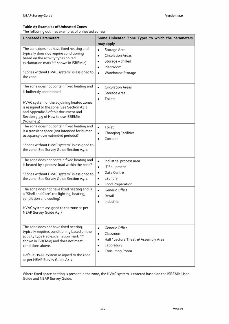
NEAP Survey Guide Version: 2.0
114 Aug 19
Table A7 Examples of Unheated Zones The following outlines examples of unheated zones:
Where fixed space heating is present in the zone, the HVAC system is entered based on the iSBEMie User Guide and NEAP Survey Guide.
Unheated Parameters Some Unheated Zone Types to which the parameters
may apply
The zone does not have fixed heating and typically does not require conditioning based on the activity type (no red exclamation mark “!” shown in iSBEMie) “Zones without HVAC system” is assigned to the zone.
• Storage Area
• Circulation Areas
• Storage – chilled
• Plantroom
• Warehouse Storage
The zone does not contain fixed heating and
is indirectly conditioned
HVAC system of the adjoining heated zones is assigned to the zone. See Section A4.2 and Appendix 8 of this document and Section 3.5.9 of How to use iSBEMie (Volume 2)
• Circulation Areas
• Storage Area
• Toilets
The zone does not contain fixed heating and is a transient space (not intended for human occupancy over extended periods)? “Zones without HVAC system” is assigned to the zone. See Survey Guide Section A4.2.
• Toilet
• Changing Facilities
• Corridor
The zone does not contain fixed heating and is heated by a process load within the zone? “Zones without HVAC system” is assigned to the zone. See Survey Guide Section A4.2.
• Industrial process area
• IT Equipment
• Data Centre
• Laundry
• Food Preparation
The zone does not have fixed heating and is a “Shell and Core” (no lighting, heating, ventilation and cooling) HVAC system assigned to the zone as per NEAP Survey Guide A4.7
• Generic Office
• Retail
• Industrial
The zone does not have fixed heating, typically requires conditioning based on the activity type (red exclamation mark “!” shown in iSBEMie) and does not meet conditions above. Default HVAC system assigned to the zone as per NEAP Survey Guide A4.2
• Generic Office
• Classroom
• Hall / Lecture Theatre/ Assembly Area
• Laboratory
• Consulting Room
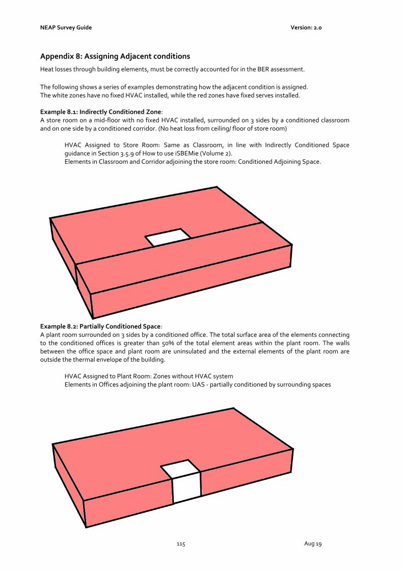
NEAP Survey Guide Version: 2.0
115 Aug 19
Appendix 8: Assigning Adjacent conditions
Heat losses through building elements, must be correctly accounted for in the BER assessment.
The following shows a series of examples demonstrating how the adjacent condition is assigned. The white zones have no fixed HVAC installed, while the red zones have fixed serves installed. Example 8.1: Indirectly Conditioned Zone: A store room on a mid-floor with no fixed HVAC installed, surrounded on 3 sides by a conditioned classroom and on one side by a conditioned corridor. (No heat loss from ceiling/ floor of store room)
HVAC Assigned to Store Room: Same as Classroom, in line with Indirectly Conditioned Space guidance in Section 3.5.9 of How to use iSBEMie (Volume 2). Elements in Classroom and Corridor adjoining the store room: Conditioned Adjoining Space.
Example 8.2: Partially Conditioned Space: A plant room surrounded on 3 sides by a conditioned office. The total surface area of the elements connecting to the conditioned offices is greater than 50% of the total element areas within the plant room. The walls between the office space and plant room are uninsulated and the external elements of the plant room are outside the thermal envelope of the building.
HVAC Assigned to Plant Room: Zones without HVAC system Elements in Offices adjoining the plant room: UAS - partially conditioned by surrounding spaces
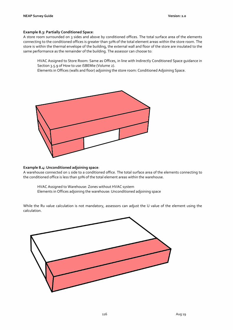
NEAP Survey Guide Version: 2.0
116 Aug 19
Example 8.3: Partially Conditioned Space: A store room surrounded on 3 sides and above by conditioned offices. The total surface area of the elements connecting to the conditioned offices is greater than 50% of the total element areas within the store room. The store is within the thermal envelope of the building, the external wall and floor of the store are insulated to the same performance as the remainder of the building. The assessor can choose to:
HVAC Assigned to Store Room: Same as Offices, in line with Indirectly Conditioned Space guidance in Section 3.5.9 of How to use iSBEMie (Volume 2). Elements in Offices (walls and floor) adjoining the store room: Conditioned Adjoining Space.
Example 8.4: Unconditioned adjoining space: A warehouse connected on 1 side to a conditioned office. The total surface area of the elements connecting to the conditioned office is less than 50% of the total element areas within the warehouse.
HVAC Assigned to Warehouse: Zones without HVAC system Elements in Offices adjoining the warehouse: Unconditioned adjoining space
While the Ru value calculation is not mandatory, assessors can adjust the U value of the element using the calculation.

NEAP Survey Guide Version: 2.0
117 Aug 19
The following flow chart gives details of when to assign alternate conditions:
Does the element connect to a zone with fixed services
YesIs the adjoining space heated to a similar temperature (+/- 5oC) as
the zone and for 75% or more of the duration of the zone being specified
No
Does the element connect to a zone that is indirectly conditioned as per iSBEMie
User Guide
YesIndirectly conditioned zone:
Element connects to: Conditioned adjoining space HVAC in Adjoining Zone: Assign HVAC as per Appendix 4.2
No
Does the element connect to a zone where 100% of the elements in the
adjoining zone are adjoining conditioned spaces (see example 8.1)
Yes
No
Does the element connect to a zone where >50% of the elements in the
adjoining zone are adjoining conditioned spaces (see example 8.2 &
8.3)
No Yes
No Yes
Element connects to: Conditioned adjoining space HVAC in Adjoining Zone: Assign HVAC as per Appendix 7
Indirectly conditioned zone:Element connects to: Conditioned adjoining space
HVAC in Adjoining Zone: Assign HVAC as per Appendix 4.2
Yes
Is the adjoining zone likely to be indirectly conditioned by the surrounding zones, ie
1) are the walls between the conditioned and unconditioned zones uninsulated
2) are the heat loss elements within the adjoining zone insulated
Does the element connect to a zone where<50% of the elements in the
adjoining zone are adjoining conditioned spaces (see example 8.4)
No
Partially conditioned zone:Element connects to: UAS – partially conditioned by
surrounding spaces HVAC in Adjoining Zone: Zone without HVAC
Indirectly conditioned zone:Element connects to: Conditioned adjoining space
HVAC in Adjoining Zone: Assign HVAC as per Appendix 4.2
Yes
Unconditioned/ Strongly Ventilated zone:Element connects to: Unconditioned adjoining space/
Strongly Ventilated Space as appropriateHVAC in Adjoining Zone: Zone without HVAC
NoElement connects to: Assign Exterior/ Underground/ Same
Space as appropriate

NEAP Survey Guide Version: 2.0
118 Aug 19

NEAP Survey Guide Version: 2.0
119 Aug 19
Adjoining spaces, either within the building being assessed or the adjoining building are treated as follows in iSBEMie:
a) “Conditioned Adjoining Space” if the space adjoining the element (zx/xx/xi) has the same activity as the zone (zx/xx) or is normally heated to similar levels as the zone (i.e. heated to a similar temperature (+/-5oC) for 75% or more of the duration of the zone being specified.)
b) “Unheated Adjoining Space” or “Strongly ventilated spaces” if the above condition is not met.
The heating regime of the adjoining space is determined as follows: 1) If there is access to details of the zones within the adjoining building, base the parameters for the element
on the activity and installed HVAC system within that zone. 2) If there is no access to the zones in the adjoining building, base the parameter for the element on the
building type using the following simple matrix showing when a building is adjoining another building whether it is considered conditioned or unconditioned / strongly ventilated.
CAS - Conditioned Adjoining Space Unconditioned Adjoining Space/ Strongly Ventilated Space
Ad
join
ing
Bu
ild
ing
Oth
ers
– P
asse
ng
er T
erm
inal
s
Co
mm
un
ity/
Day
care
Cen
tre
Pri
mar
y H
ealt
h C
are
Bu
ildin
g
Res
iden
tial
Inst
itu
tio
ns
Res
tau
ran
t an
d C
afes
/Dri
nki
ng
Est
ablis
hm
ents
an
d H
ot
Fo
od
Lib
rari
es M
use
um
s an
d G
alle
ries
Off
ices
an
d W
ork
sho
p b
usi
ne
sses
Res
iden
tial
sp
aces
Ed
uca
tio
n
Ret
ail a
nd
Fin
anci
al/P
rofe
ssio
nal
ser
vice
s
Gen
eral
A
ssem
bly
an
d
Le
isu
re
plu
s N
igh
t
Clu
bs
and
Th
eatr
es
Sto
rag
e an
d D
istr
ibu
tio
n
Oth
ers
- C
ar P
arks
24
hrs
. Building in BER Assessment
Others – Passenger Terminals
Community/Daycare Centre
Primary Health Care Building
Residential Institutions
Restaurant and Cafes/Drinking Establishments and Hot Food
Libraries Museums and Galleries
Offices and Workshop businesses
Residential spaces
Education
Retail and Financial/Professional services
General Assembly and Leisure plus Night Clubs and Theatres
Storage and Distribution
Others - Car Parks 24 hrs

NEAP Survey Guide Version: 2.0
120 Aug 19
Appendix 9: Determining the Hot Water Storage Volume and Secondary Circulation Losses
Where there is access to the hot water storage unit, determine the storage volume as follows: a. Determine the hot water storage volume from a label on the storage unit, provided the label
also references a European or National Standard or is CE marked. b. Take note of the Manufacturer and Model of the unit and determine the volume from
literature from the manufacturer referencing the relevant standards. c. Take note of the Manufacturer and Model of the unit and contact the manufacturer regarding
the storage volume. The manufacturer must provide written confirmation of the storage volume.
d. Where data from the above sources is unavailable and the vessel is accessible, measure the volume of the unit on site. Further detail on this is provided below.
e. Where the hot water storage vessel is inaccessible, documentary evidence from the installer, architect or engineer identifying the volume of the installed vessel is used.
f. If none of these options are possible base it on the iSBEMie default. Measuring a Hot Water Storage Cylinder:
1) Measure the height and diameter of the hot water storage vessel. 2) For cylindrical vessels that are between 71 and 441 litres, choose the nearest height and diameter options
from the table below to determine the volume in litres. Insulation thickness is not included in the height or diameter measurement when using the table. The table below is based on BS1566 and applies to copper cylinders, however, these figures are also used for other types of storage vessels for the purposes of NEAP assessments. The storage vessel diameter is determined based on vessel circumference, dividing the circumference by π (3.14). Diameter should not include insulation thickness.
Diameter (mm) Height (mm) Storage volume
300 1600 96
350 900 72
400 900 96
400 1050 114
450 675 84
450 750 95
450 825 106
450 900 117
450 1050 140
450 1200 162
450 1500 206
500 1200 190
500 1500 245
600 1200 280
600 1500 360
600 1800 440
3) For cylindrical vessels outside this range, the volume is calculated based on the following:
V = (pi x r2) x h / 1000

NEAP Survey Guide Version: 2.0
121 Aug 19
Where: r = radius of the unit (cm) h = height of the unit (cm) pi = 3.142 V = volume of unit (litres)
For Enclosed Water Heaters: The water heater volume is calculated by recording the height, width and depth of the water heater if the heater is cuboid or the above formula if cylindrical. The cuboid volume is then calculated as follows: V = h x d x w x 1000 Where: d = depth of unit (m) minus the insulation thickness as appropriate.
h = height of unit (m) minus the insulation thickness as appropriate. w = width of unit (m) minus the insulation thickness as appropriate V = volume of the cylinder (litres)
For example The diagram below shows a water heater with measured dimensions on site for a unit installed in 2005. The default insulation thickness is therefore 35mm.
The volume of the storage unit is therefore: V = h x d x w x 1000 h = 550 – (35 x 2) = 480mm d = 330 – (35 x 2) = 260mm w = 330 – (35 x 2) = 260mm Volume = 0.48 x 0.26 x 0.26 x 1000 = 32 litres Secondary Circulation Losses:
Insulation of hot water pipework can be accounted for in the iSBEMie calculation. The table below gives indicative thickness of insulation for non-domestic hot water services to meet the maximum permissible heat loss set out in TGD L 2017.
Outside diameter of pipe on which Water temperatures at 60oC for hot water with ambient still air of

NEAP Survey Guide Version: 2.0
122 Aug 19
insulation thickness has been based mm 15oC.
Thermal Conductivity at insulation mean temperature W/mK
0.025 0.030 0.035 0.040 0.045
Maximum permissible heat loss W/m Thickness of insulation
17.2 12 17 23 31 41 6.60
21.3 14 19 25 33 43 7.13
26.9 15 21 27 35 45 7.83
33.7 17 22 29 37 47 8.62
42.4 18 23 30 38 47 9.72
48.3 19 25 32 40 49 10.21
60.3 20 26 33 41 50 11.57
76.1 22 28 35 43 52 13.09
88.9 22 28 35 43 51 14.58
114.3 23 29 36 43 51 17.20
139.7 24 31 37 44 52 19.65
168.3 25 32 38 45 53 22.31
219.1 26 32 38 45 52 27.52
273 and above 27 33 39 46 53 32.40
(Ref The TIMSA HVAC Guidance Document) For entering the data into iSBEMie the assessor must get the average w/m, for example; Hot Water Secondary Circulation installed with following pipework length and heat loss: 100m 17.2 dia 6.60 w/m 50m 33.7 dia 8.62 w/m 10m 76.1 dia 13.09 w/m Average = 100 x 6.6 + 50 x 8.62 + 10 x 13.09 = 7.64 w/m 100 + 50 + 10

NEAP Survey Guide Version: 2.0
123 Aug 19
Appendix 10: Selection of Solid Fuel Type, Open fires & stoves
10.1: Selection of solid fuel type:
Solid fuel appliances can be fueled by coal, anthracite, smokeless fuel, dual fuel (mineral and wood) and biomass.
For solid fuel boilers and heaters the fuel type is chosen as follows, proceeding from points 1 towards 4 until a choice is made:
1) If the heating appliance is designed to burn only biomass, i.e. its design is such as to prohibit the use of any other fuel type, then the appropriate fuel type (biomass) should be selected. Otherwise biomass should not be selected. This can be demonstrated by one of the following:
i. Documentation showing that the product warranty is void if the product is used with any fuel type other than biomass ;
ii. Listing of the product under http://www.hetas.co.uk/ showing that the appliance burns biomass only.
Where there is any doubt about fuel type selection biomass should not be selected. 2) If the appliance is designed to burn a particular coal-based or peat-based fuel type, then that
should be chosen as the fuel. 3) If the appliance can burn more than one fuel type, the most likely non-biomass type should
be selected based on (a) the appliance design, and (b) the building location (taking account of smoke control areas and fuels common in the area).
The following table summarises the information above:
Scenario Biomass Manufactured smokeless fuel One of coal or anthracite
Appliance can only burn biomass
Yes No No
Appliance can burn multiple solid fuels but a particular fuel is the most commonly available or applicable non-biomass fuel in the area
No Yes - Select manufactured smokeless fuel when building is in “smoke control area” and
the appliance can burn multiple fuels
Yes - Select one of these fuels when building is in non “smoke
control area” and that fuel is clearly the most commonly
available fuel in the area
Smoke control areas (also called coal restricted areas) can be identified using the facility under http://maps.epa.ie or following guidance on the Department of Environment, Community and Local Government website. Individual Local Authorities may have further details.
10.2: Open fires & stoves
Open fires and stoves can be encountered in older buildings and some public houses. The following table describes the entries.
“Appliance” System Type Heat Source Fuel Type Seasonal Efficiency
Open Fire Other local room heater - unfanned
Room Heater Refer to guidance above
Enter 0.3
Stove Other local room heater - unfanned
Room Heater Refer to guidance above Use the default 0.7 unless a non-default figure can be obtained
Where another heating source e.g. central heating using a boiler is present a bi-valent system may be required,
or the space may need to zoned appropriately.
If the BER Assessor can determine that the chimney has been closed the appliance can be ignored.
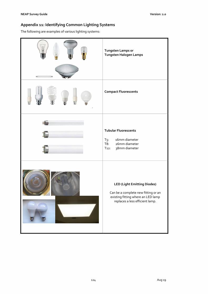
NEAP Survey Guide Version: 2.0
124 Aug 19
Appendix 11: Identifying Common Lighting Systems
The following are examples of various lighting systems:
Tungsten Lamps or Tungsten Halogen Lamps
.
Compact Fluorescents
Tubular Fluorescents
T5: 16mm diameter T8: 26mm diameter T12: 38mm diameter
LED (Light Emitting Diodes)
Can be a complete new fitting or an existing fitting where an LED lamp
replaces a less efficient lamp.

NEAP Survey Guide Version: 2.0
125 Aug 19
.
Metal Halide
Appendix 12: Fuel Conversion Factors
The following table lists the Fuel Conversion Factors and Primary Energy Factors used by iSBEMie.
Fuel type kgCO2/kWh Non Renewable Primary Energy Factor kWh/kWh
Renewable Primary Energy Factor kWh/kWh
Natural gas 0.203 1.1 0
LPG 0.232 1.1 0
Biogas 0.025 0.1 1
Fuel oil 0.272 1.1 0
Coal 0.361 1.1 0
Anthracite 0.361 1.1 0
Manufactured smokeless fuel 0.392 1.2 0
Dual fuel (mineral + wood) 0.289 1.1 0
Biomass 0.025 0.1 1
Grid supplied electricity 0.409 Grid Electricity 0
Grid displaced electricity 0.409 Grid Electricity 0
Electricity produced by renewables (PV/ Wind)
- 0 Grid Electricity
Solar Thermal - 0 1
Heat Pump (Environmental Energy) - 0 1
District Heating District Heating Supplier
District Heating Supplier
District Heating Supplier
Related Documents