NON-CONVENTIONAL MACHINING OF Al/SiC METAL MATRIX COMPOSITE June 2012 Debaprasanna Puhan Production Engineering Department of Mechanical Engineering National Institute of Technology, Rourkela

Welcome message from author
This document is posted to help you gain knowledge. Please leave a comment to let me know what you think about it! Share it to your friends and learn new things together.
Transcript

NON-CONVENTIONAL MACHINING OF Al/SiC METAL MATRIX COMPOSITE
June
2012
Debaprasanna Puhan Production Engineering
Department of Mechanical Engineering National Institute of Technology, Rourkela
NON-CONVENTIONAL MACHINING OF Al/SiC METAL
MATRIX COMPOSITE
A THESIS SUBMITTED IN PARTIAL FULFILLMENT OF THE REQUIREMENTS FOR THE DEGREE OF
MASTER OF TECHNOLOGY IN
PRODUCTION ENGINEERING
[MECHANICAL ENGINEERING]
By
DEBAPRASANNA PUHAN
210ME2243
Under the supervision of
Prof. S. S. MAHAPATRA
DEPARTMENT OF MECHANICAL ENGINEERING NATIONAL INSTITUTE OF TECHNOLOGY, ROURKELA
ODISHA, INDIA-769008

Dedicated to my parents, Guide &Friends
*

NATIONAL INSTITUTE OF TECHNOLOGY
ROURKELA-769008
CERTIFICATE
This is to certify that the thesis entitled “NON-CONVENTIONAL
MACHINING OF Al/SiC METAL MATRIX COMPOSITE” which is
being submitted by DEBAPRASANNA PUHAN as partial fullfilment of
Master of Technology degree in Production Engineering (Mechanical
Engineering) during the academic year 2010-2012 in the Department of
Mechanical Engineering, National Institute of Technology, Rourkela.
Date: Prof. Siba Sankar Mahapatra
Department of Mechanical Engineering National Institute of Technology
Rourkela-769008
ACKNOWLEDGEMENTACKNOWLEDGEMENTACKNOWLEDGEMENTACKNOWLEDGEMENT
Successful completion of work will never be one man’s task. It requires hard work
in right direction. There are many who have helped to make my experience as a student a
rewarding one. In particular, I express my gratitude and deep regards to my thesis
supervisor Dr. S.S. Mahapatra, Department of Mechanical Engineering, NIT
Rourkela for kindly providing me to work under his supervision and guidance. I extend
my deep sense of indebtedness and gratitude to him first for his valuable guidance,
inspiring discussions, constant encouragement & kind co-operation throughout period of
work which has been instrumental in the success of thesis.
I extend my thanks to Dr. K.P. Maity, and Head, Dept. of Mechanical
Engineering for extending all possible help in carrying out the dissertation work directly
or indirectly.
I express my sincere gratitude to Dr. Saurav Datta, Kunal Nayak, Dept. of
Mechanical Engineering and Mr. Uday Kumar Sahu, Dept. of Metallurgical and
Materials Engineering, NIT, Rourkela and other staff members for their indebted help
in carrying out experimental work and valuable suggestions. I am also thankful to all the
staff members of the department of Mechanical Engineering, NIT Rourkela and to all my
well-wishers for their inspiration and help.
I greatly appreciate & convey my heartfelt thanks to Shailesh Dewangan, Chinmaya
Mohanty, Jambeswar Sahu, Layatitdev Das, Chitrasen Samantra, Ashribad Swain,
Ankita Singh dear ones & all those who helped me in completion of this work.
I feel pleased and privileged to fulfill my parent’s ambition and I am greatly
indebted to them for bearing the inconvenience during my M Tech. course.
DEBAPRASANNA PUHAN
ii

DECLARATIONDECLARATIONDECLARATIONDECLARATION
We hereby declare that the thesis entitled “NON-CONVENTIONAL
MACHINING OF Al/SiC METAL MATRIX COMPOSITE” is a bonafied record of
work done by me, as a functional part towards the fulfillment of Master of Technology
degree in Production Engineering specialization (Mechanical) from National Institute of
Technology, Rourkela during the academic year 2010-2012.
This is purely academic in nature and it has not formed the basis, for the award of
any Degree/ Diploma/Ascertain ship/ fellowship or similar title to any candidate.
iii
DEBAPRASANNA PUHAN
ROLL NO. 210ME2243

iv
ABSTRACT
In recent years, aluminum alloy based metal matrix composites (MMC) are gaining importance
in several aerospace and automobile applications. Aluminum has been used as matrix material
owing to its excellent mechanical properties coupled with good formability. Addition of SiCp as
reinforcement in aluminium system improves mechanical properties of the composite. In the
present investigation, Al-SiCp composite was prepared by powder metallurgy route. Powder
metallurgy homogeneously distributes the reinforcement in the matrix with no interfacial
chemical reaction and high localized residual porosity. SiC particles containing different weight
fractions (10 and 15 wt. %) and mesh size (300 and 400) is used as reinforcement .Though AlSiC
possess superior mechanical properties, the high abrasiveness of the SiC particles hinders its
machining process and thus by limiting its effective use in wide areas. Rapid tool wear with poor
performance even with advanced expensive tools categories it as a difficult-to-cut material. Non-
conventional processes such as electrical discharge machining (EDM) could be one of the best
suited method to machine such composites. Four machining parameters such as discharge current
(Ip), pulse duration (Ton), duty cycle (τ),flushing pressure (Fp) and two material properties
weight fraction of SiCp and mesh size, and four responses like material removal rate (MRR), tool
wear rate (TWR), circularity and surface roughness (Ra) are considered in this study. Taguchi
method is adopted to design the experimental plan for finding out the optimal setting. However,
Taguchi method is well suited for single response optimization problem. In order to
simultaneously optimize multiple responses, a hybrid approach combining principal component
analysis (PCA) and fuzzy inference system is coupled with Taguchi method for the optimization
of multiple responses. The influence of each parameter on the responses is established using
analysis of variances (ANOVA) at 5% level of significance. It is found that discharge current,
pulse duration, duty cycle and wt% of SiC contribute significantly, where flushing pressure and
mesh size of SiCp contribute least to the multiple performance characteristic index.
Keywords: Powder metallurgy; Sintering; Heat Treatment; Electrical Discharge Machining;
Taguchi Method; Principal Component Analysis; Fuzzy Inference System: Analysis
of Variance; Weighted Principal Component Analysis; Thermo-Physical Modeling;
v
Contents Description Page
No Certificate i
Acknowledgement ii
Declaration iii
Abstract iv
Contents v
List of figures vii
List of tables x
Glossary of terms xi
Chapter-1 Background and motivation 1 1.1 Introduction 2 1.2 Composites 2 1.2.1 Classification of composites 3 1.2.2 Components of a composite material 5 1.3 Metal matrix composite 5 1.3.1 Characteristics of MMC 7 1.3.2 Advantages and disadvantages of MMC 7 1.4 Matrix material 8 1.5 Reinforcement 9 1.6 Reinforcement characteristics 10 1.7 Al/SiC MMC 10 1.8 Production technologies for MMC 11 1.8.1 MMC fabrication methods (Primary processing) 11 1.8.2 MMC machining methods (Secondary processing) 12 1.9 Research objectives 14 1.10 Thesis outline 15 Chapter-2 Literature Survey 17 2.1 Introduction 18 2.2 Powder metallurgy 18 2.3 electrical Discharge Machining (EDM) 19 2.3.1 Mechanism of material removal 19

vi
2.3.2 EDM process parameters 20 2.3.3 EDM performance measures 21 2.4 Multi-objective optimization 23 2.5 Conclusion 24 Chapter-3 Experimental details 25 3.1 Introduction 26 3.2 Material 26 3.2.1 Aluminium Alloy 26 3.2.2 SiC particulates 26 3.2.3 Pre-treatment of SiC particulates 26 3.3 Specimen fabrication 27 3.4 Powder metallurgy method 28 3.4.1 Mixing of powders 28 3.4.2 Compaction of the powder mix 28 3.4.3 Cold uniaxial pressing 29 3.4.4 sintering of the green samples 29 3.4.5 Heat treatment 30 3.4.5.1 Quenching 30 3.4.5.2 Ageing 31 3.5 Results & discussions 32 3.5.1 XRD analysis 32 3.5.2 Density 33 3.5.3 Hardness 34 3.5.4 Conductivity 35 3.5.5 Microstructure analysis 36 3.6 Design of Experiments 38 3.7 Taguchi experimental design 39 3.8 electrical discharge machining process 40 3.8.1 Material removal rate (MRR) 42 3.8.2 Tool wear rate (TWR) 42 3.8.3 Surface roughness 42 3.8.4 Circularity 43 3.9 Conclusion 43 Chapter-4 Methodology 44
4.1 Introduction 45 4.2 Taguchi method 46 4.2.1 Performance evaluation 46 4.3 Principal component analysis 48 4.4 Fuzzy inference system 50

vii
4.5 weighted principal component analysis 54 4.6 Conclusion 55
Chapter-5 Results and discussion 56 5.1 Introduction 57 5.2 System performance evaluation and standardization 57 5.3 Principal component analysis 59 5.4 Fuzzy inference system 62 5.5 Effect of control factors on the MPCI 66
5.6 Analysis of variance (ANOVA) 67 5.7 Weighted principal component analysis 68 5.7.1 Effect of the control factors on the MPCI 69 5.7.2 Analysis of variance (ANOVA) 70 5.8 Performance prediction of the optimal design parameters 71 5.9 Confirmation run 72 5.10 Confirmation by Thermo-Physical modeling 72 5.10.1 Thermal analysis of the EDM process 72 5.10.2 Assumptions 73 5.10.3 Heat input, spark radius boundary condition and MRR 73 5.10.4 Solution methodology 74 5.10.5 Results and comparison of models 75
Chapter-6 Conclusions 78 6.1 Introduction 79 6.2 Summery of findings 79
References 82 List of publications 93
viii
LIST OF FIGURES
Figure Title Page No
1.1 Classification of composites 4 1.2 Schematic overview of the production processes about MMCs 14 3.1 Muffle furnace 27 3.2 Ball planetary mill 28 3.3 Cold uniaxial pressing machine 29 3.4 Horizontal tubular furnace 30 3.5 Heat treatment furnace 30 3.6 Muffle furnace 31 3.7 Sintered samples 31 3.8 XRD instrument 32 3.9 The XRD graphs 33 3.10 Vickers hardness measuring machine 34 3.11 Variation of hardness with % of SiC 35 3.12 Digital electrical conductivity measuring device 35 3.13 Scanning Electron Microscope 37
3.14 Micrographs showing the distribution of reinforcement in the composite (green samples)
37
3.15 Micrographs showing Aluminium and voids in the composite (green samples)
38
3.16 Electrical Discharge Machine 41 3.17 Copper tool (electrode) 41 3.18 Machined AlSiC composites 41 3.19 Electronic balance weight measuring machine 42 3.20 Stylus type profilometre 43 3.21 Optical microscope 43 3.22 Feret’s diameters 43 4.1 Structure of fuzzy rule based system 52 5.1 Structure of Mamdani model 63 5.2 Membership functions for the inputs 63 5.3 Membership functions for the output 63 5.4 Calculation of MPCI for experiment number 1 65 5.5 Surface plots between Principal components (PCs) and MPCI 65 5.6 Response graph for MPCI value 67

ix
5.7 Response graph for MPCI value (WPCA) 70 5.8 Two-dimensional axisymmetric model 71 5.9 Temperature distribution 76 5.10 Predicted crater using the FEM analysis 76

x
List of Tables
Table No Title Page No
3.1 Properties of the samples 36 3.2 Control parameters and their levels 39 3.3 L16 Orthogonal array 40 5.1 Experimental layout of L16 orthogonal array 58 5.2 S/N ratio of responses 58 5.3 Normalization S/N ratio of responses 60 5.4 Correlation coefficient matrix for the responses 61
5.5 Eigenvalues, eigenvectors, proportion explained and cumulative proportion explained computed for the four responses
61
5.7 Fuzzy rule matrix 64 5.8 MPCI values for 16 experiments 66 5.9 Response effect on MPCI 67 5.10 Analysis of variance (ANOVA) on MPCI 68 5.11 MPCI values for 16 experiments (WPCA) 69 5.12 Response effect on MPCI (WPCA) 69 5.13 Analysis of variance (ANOVA) on MPCI(WPCA) 71 5.14 Comparison between initial and optimal conditions 72 5.15 Comparison between ANSYS and actual MRR 77

xi
Glossary of terms
Al/SiC Aluminium Silicon Carbide
MMC Metal Matrix Composites
PMC Polymer Matrix Composites
CMC Ceramic Matrix Composites
PM or P/M Powder Metallurgy
XRD X-Ray Diffraction
HT Heat Treatment
EDM Electrical Discharge Machining
MRR Material Removal Rate
TWR Tool Wear Rate
S/N Signal to Noise
PCA Principal Component Analysis
FIS Fuzzy Inference System
WPCA Weighted Principal Component Analysis
ANOVA Analysis of Variance
MPC Multi Performance Characteristics
MPCI Multi Performance Characteristics Index

Non-conventional Machining of AlSiC Metal Matrix Composite 2012
Department of Mechanical Engineering, NIT, Rourkela, India Page 1
CHAPTER-1
BACKGROUND AND MOTIVATION

Non-conventional Machining of AlSiC Metal Matrix Composite 2012
Department of Mechanical Engineering, NIT, Rourkela, India Page 2
CHAPTER-1
BACKGROUND AND MOTIVATION
1.1 Introduction
Composite materials play an important role in the field of engineering as well as advance
manufacturing in response to unprecedented demands from technology due to rapidly advancing
activities in aircrafts, aerospace and automotive industries. These materials have low specific
gravity that makes their properties particularly superior in strength and modulus to many
traditional engineering materials such as metals. As a result of intensive studies into the
fundamental nature of materials and better understanding of their structure property relationship,
it has become possible to develop new composite materials with improved physical and
mechanical properties. These new materials include high performance composites such as
reinforced composites. Continuous advancements have led to the use of composite materials in
more and more diversified applications. The importance of composites as engineering materials
is reflected by the fact that out of over 1600 engineering materials available in the market today
more than 200 are composite [1].
1.2 Composites
The typical composite materials are engineered or naturally occurring materials made from
two or more constituent materials with significantly different physical or chemical properties
which remain separate and distinct at the macroscopic or microscopic scale within the finished
structure. The constituents retain their identities, that is, they do not dissolve or merge
completely into one another although they act in concert.
The individual materials that make up composites are called constituents. Most composites
have two constituent materials: a binder or matrix (polymers, metals, or ceramics) and
reinforcement (fibers, particles, flakes, and/or fillers). The reinforcement is usually much
stronger and stiffer than the matrix, and gives the composite its good properties. The matrix
holds the reinforcements in an orderly pattern. Because the reinforcements are usually
discontinuous, the matrix also helps to transfer load among the reinforcements. Some authors
defined composite as:

Non-conventional Machining of AlSiC Metal Matrix Composite 2012
Department of Mechanical Engineering, NIT, Rourkela, India Page 3
Berghezan [2] stated as “The composites are compound materials which differ from alloys
by the fact that the individual components retain their characteristics but are so incorporated into
the composite as to take advantage only of their attributes and not of their shortcomings”.
There are two major reasons for the current interest in composite materials. The first is
simply the need for materials that will outperform the traditional monolithic materials. The
second and more important in the long run is that composite offer engineers the opportunity to
design totally new materials with the precise combination of properties needed for specific tasks.
1.2.1 Classification of composites
Composites are classified in various ways by different authors but in simplest and broadest
sense this may be classified as (i) Natural, and (ii) Man-made or synthetic (Figure 1.1).
The composites that occur in nature are called natural composites such as, wood (composed of
cellulose fires and lignin support), human or animal body (composed of bones and tissues).
Bones, sea shells and elephant tusk are also considered as the examples of natural composites
provided by nature [3].
The reinforced composites are classified in two ways: (i) on the basis of matrix used and
(ii) on the basis of the geometry of the reinforcement. Based on the matrix phase used,
multiphase composites are divided into three categories:
a) Polymer-matrix composites (PMCs).
b) Ceramic-matrix composites (CMCs).
c) Metal-matrix composites (MMCs).

Non-conventional Machining of AlSiC Metal Matrix Composite 2012
Department of Mechanical Engineering, NIT, Rourkela, India Page 4
Figure 1.1 Classification of composites
CMC
Layered composition (Structural composites)
Man-made
Composites
Natural
Wood Lignin + Cellulose Human/Animal body (Bones + Tissues) Bones (Organic + Inorganic comp)
Phase composition
Filled composition Reinforced composition
Reinforcement (geometry) Matrix (material)
Particulate Flake PMC Fibrous MMC
Continuous Discontinuous Dispersion Strengthened
Particle Strengthened
Random Oriented
Uniaxially Biaxially Triaxially Multiaxially
Cross ply Angle ply
Non-conventional Machining of AlSiC Metal Matrix Composite 2012
Department of Mechanical Engineering, NIT, Rourkela, India Page 5
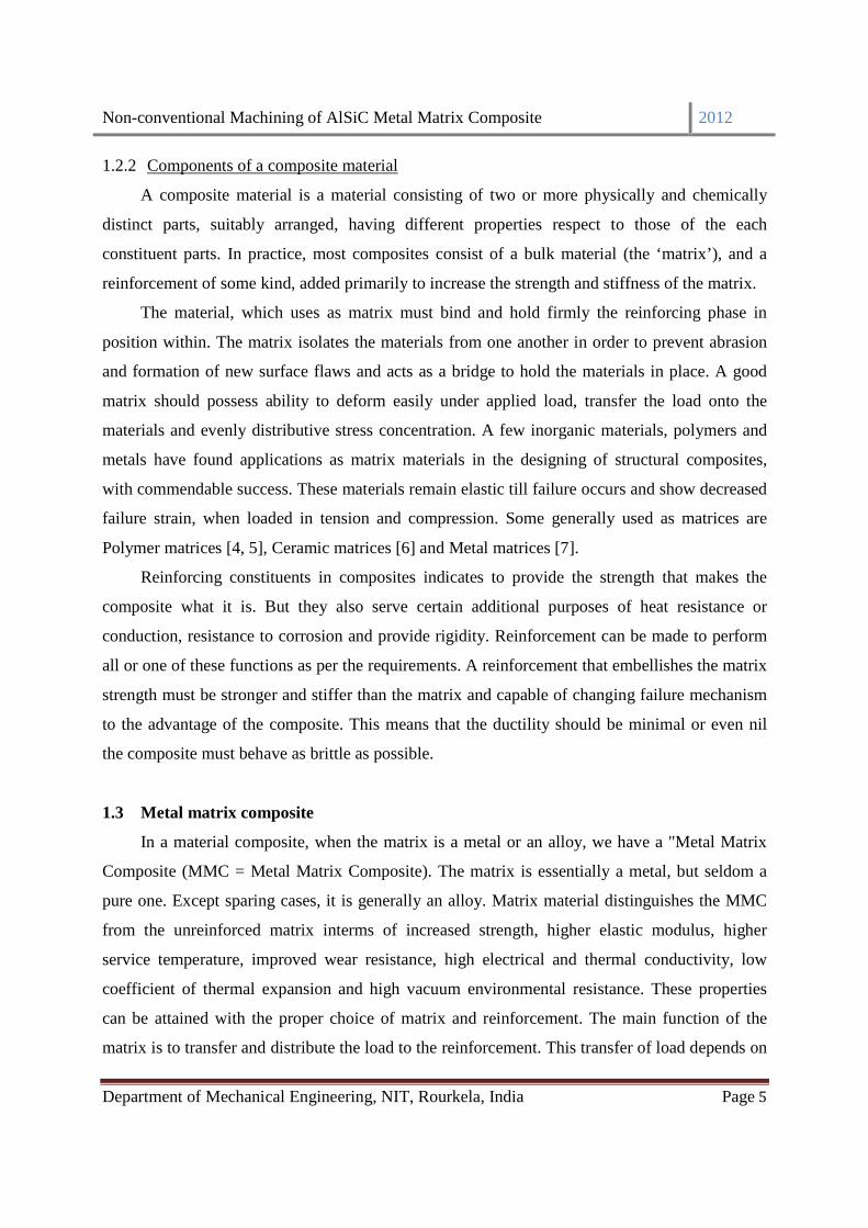
1.2.2 Components of a composite material
A composite material is a material consisting of two or more physically and chemically
distinct parts, suitably arranged, having different properties respect to those of the each
constituent parts. In practice, most composites consist of a bulk material (the ‘matrix’), and a
reinforcement of some kind, added primarily to increase the strength and stiffness of the matrix.
The material, which uses as matrix must bind and hold firmly the reinforcing phase in
position within. The matrix isolates the materials from one another in order to prevent abrasion
and formation of new surface flaws and acts as a bridge to hold the materials in place. A good
matrix should possess ability to deform easily under applied load, transfer the load onto the
materials and evenly distributive stress concentration. A few inorganic materials, polymers and
metals have found applications as matrix materials in the designing of structural composites,
with commendable success. These materials remain elastic till failure occurs and show decreased
failure strain, when loaded in tension and compression. Some generally used as matrices are
Polymer matrices [4, 5], Ceramic matrices [6] and Metal matrices [7].
Reinforcing constituents in composites indicates to provide the strength that makes the
composite what it is. But they also serve certain additional purposes of heat resistance or
conduction, resistance to corrosion and provide rigidity. Reinforcement can be made to perform
all or one of these functions as per the requirements. A reinforcement that embellishes the matrix
strength must be stronger and stiffer than the matrix and capable of changing failure mechanism
to the advantage of the composite. This means that the ductility should be minimal or even nil
the composite must behave as brittle as possible.
1.3 Metal matrix composite
In a material composite, when the matrix is a metal or an alloy, we have a "Metal Matrix
Composite (MMC = Metal Matrix Composite). The matrix is essentially a metal, but seldom a
pure one. Except sparing cases, it is generally an alloy. Matrix material distinguishes the MMC
from the unreinforced matrix interms of increased strength, higher elastic modulus, higher
service temperature, improved wear resistance, high electrical and thermal conductivity, low
coefficient of thermal expansion and high vacuum environmental resistance. These properties
can be attained with the proper choice of matrix and reinforcement. The main function of the
matrix is to transfer and distribute the load to the reinforcement. This transfer of load depends on

Non-conventional Machining of AlSiC Metal Matrix Composite 2012
Department of Mechanical Engineering, NIT, Rourkela, India Page 6
the bonding which depends on the type of matrix and reinforcement and the fabrication
technique [8].
Generally MMCs are classified according to type of used reinforcement and the geometric
characteristics of the same. Normally, the main classification of composites can be made in the
form of reinforcement groups into two basic categories:
a. Continuous reinforcement composites, constituted by continuous fibers or filaments;
b. Discontinuous reinforced composites, containing short fibers, whiskers or particles.
1.3.1 Characteristics of MMCs
Metal Matrix Composites, alternatives to conventional materials, provide the specific
mechanical properties necessary for elevated as well as ambient temperature applications. The
performance advantages of these materials include their tailored mechanical, physical and
thermal properties in light of their low density, high specific modulus, high strength, high
thermal conductivity, good fatigue response, control of thermal expansion, high abrasion and
wear resistance, etc. Some of the typical applications of MMCs include their use in fabrication of
satellite, missile, helicopter structures, structural support, piston, sleeves and rims, high
temperature structures, drive shaft, brake rotors, connecting rods, engine block liners various
types of aerospace and automotive applications etc. The superior mechanical properties of
MMCs drive their use. An important characteristic of MMCs, however, and one they share with
other composites. This can be possible by appropriate selection of matrix materials,
reinforcements, and reinforcement orientations and also possible to tailor the properties of a
component to meet the needs of a specific design. The performance of these materials renders
their characteristics in terms of physical and mechanical peculiarity, depend on the nature of the
two components (chemical composition, crystalline structure, and in the case of reinforcement,
shape and size), the volume/weight fraction of the adopted reinforcement and production
technology. In general we can say that metal matrix composites utilize at the same time the
properties of the matrix (light weight, good thermal conductivity, ductility) and of the
reinforcement, usually ceramic (high stiffness, high wear resistance, low coefficient of thermal
expansion). Material characterization can be obtained by comparing the basic metal component
in terms of high values of specific strength, stiffness, wear resistance, fatigue resistance and
creep, corrosion resistance in certain aggressive environments. However, cause to the presence

Non-conventional Machining of AlSiC Metal Matrix Composite 2012
Department of Mechanical Engineering, NIT, Rourkela, India Page 7
of the ceramic component, ductility, toughness and fracture to the coefficients of thermal
expansion and reduction of thermal conductivity.
The different variety of MMCs has different distinguishable properties. Factors influencing
their characteristics include:
a. Reinforcement properties, form, and geometric arrangement.
b. Reinforcement volume/weight fraction.
c. Matrix properties, including effects of porosity.
d. Reinforcement-interface properties.
e. Residual stresses arising from the thermal and mechanical history of the composite.
f. Degradation of the reinforcement resulting from chemical reactions at high temperatures,
and mechanical damage from processing, impact, etc
1.3.2 Advantages and Disadvantages of MMC
Compared to monolithic metals, PMC and CMCs, MMCs have:
a. Higher strength-to-density ratio and stiffness-to-density ratios.
b. Better fatigue resistance and lower creep rate.
c. Better elevated temperature properties.
d. Lower coefficients of thermal expansion.
e. Better wear resistance and radiation resistance.
f. Higher temperature capability with fire resistance.
g. Higher transverse stiffness and strength.
h. No moisture absorption and no outgassing.
i. Higher electrical and thermal conductivities.
j. Fabricability of whisker and particulate-reinforced MMCs with conventional
metalworking equipment.
Some of the disadvantages of MMCs compared to monolithic metals, PMCs and CMCs are
a. Higher cost of some material systems.
b. Relatively immature technology.
c. Complex fabrication methods for fiber-reinforced systems (except for casting).
d. Limited service experience.

Non-conventional Machining of AlSiC Metal Matrix Composite 2012
Department of Mechanical Engineering, NIT, Rourkela, India Page 8
1.4 Matrix material
The matrix material should be carefully chosen depending upon its properties and
behaviour with the reinforcement. As it is the primary constituent in MMC, the matrix alloy
should be chosen only after giving careful consideration to its chemical compatibility with the
reinforcement, to its ability to wet the reinforcement, and to its own characteristics properties and
processing behaviour [9, 10]. The best properties can be obtained in a composite system when
the reinforcement whiskers or particulates and matrix are as physically and chemically
compatible as possible. Special matrix alloy compositions, in conjunction with unique whisker
coatings, have been devised to optimize the performance of certain metallic composites [11, 13].
Researchers have proposed a lot of materials as the matrix material depending on their
properties. Taya and Arsenault [13] have suggested materials like Al, Ti, Mg, Ni, Cu, Pb, Fe, Ag,
Zn, Sn and Si on the basis of oxidation and corrosion resistance properties. Among these Al, Ti,
Mg are used widely. The most common metal alloys in use are based on Aluminium and
Titanium. Both of them are low density materials and are commercially available in a wide range
of alloy compositions. Other alloys are also used for specific cases, because of their own
advantages and disadvantages. Beryllium is the lightest of all structural materials and has a
tensile modulus greater than that of steel, but it is extremely brittle, rendering it unsuitable for
general purpose use. Magnesium is light, but is highly reactive to Oxygen. Nickel and Cobalt
based super alloys have also found some use, but some of the alloying elements present in the
matrices have been found to have undesirable effect (promoting oxidation) on the reinforcing
fibers at high temperatures. Aluminum is one of the best materials for matrix because of its
unique combination of excellent mechanical and electrical properties of good corrosion
resistance low density and high toughness with high conductivity [14]. Moreover, Al is cheaper
than other light metals like magnesium (Mg). The other advantage of using Al as matrix of
MMCs is its corrosion resistance which is very important for using composites in different
environments [15]. Magnesium and its alloys do not compare favorably with aluminium alloys in
terms of absolute strength though; they are lightest materials and good combination of low
density and excellent machinability as compared with other structural materials [16]. Aluminum
based metal matrix composites (MMCs) offer potential for advanced structural applications
when high specific strength and modulus, as well as good elevated temperature resistance, high
service temperature and specific mechanical properties are important.

Non-conventional Machining of AlSiC Metal Matrix Composite 2012
Department of Mechanical Engineering, NIT, Rourkela, India Page 9
1.5 Reinforcement
Reinforcement increases the strength, stiffness and the temperature resistance capacity and
lowers the density of MMC. In order to achieve these properties the selection depends on the
type of reinforcement, its method of production and chemical compatibility with the matrix and
the following aspects must be considered while selecting the reinforcement material.
Reinforcements are characterized by their chemical composition, shape, dimensions, and
properties as in gradient material and their volume fraction and spatial distribution in the matrix
[17]. Although the largest improvement in properties (strength and stiffness) is obtained with the
introduction of fiber reinforcements but the properties of fiber-reinforced composites are not
isotropic. Particulate-reinforced MMC show the advantage of nearly isotropic properties and
cost-effectiveness. Furthermore, an additional advantage of the particulate-reinforced over fiber
reinforced MMC is that most existing processing techniques can be used for fabrication and
finishing of the composites, including hot rolling, hot forging, hot extrusion and machining [18-
21].
It is proven that the ceramic particles are effective reinforcement materials for aluminium
and its alloy to enhance the mechanical and other properties. Typically these ceramics are oxides,
carbides and nitrides. These are used because of their combinations of high strength and stiffness
at both room and elevated temperatures. Common reinforcement elements are SiC, A12O3, TiB2,
thorium, boron and graphite. The use of graphite reinforcement in a metal matrix has a potential
to create a material with a high thermal conductivity, excellent mechanical properties and
attractive damping behaviour at elevated temperatures. However, lack of wettability between
aluminium and the reinforcement, and oxidation of the graphite lead to manufacturing
difficulties and cavitations of the material at high temperatures [22]. Alumina and other oxide
particles like TiO2 etc. have been used as the reinforcing particles as it is found that these
particles increase the hardness, tensile strength and wear resistance of aluminium metal matrix
composites [23]. Silicon carbide (SiC) ceramics are promising candidates in the field of high-
temperature structural materials due to their excellent oxidation, corrosion, and creep resistance
[24]. Silicon carbide particle (SiCp) reinforced aluminium-based MMCs are among the most
common MMC and commercially available ones due to their economical production [25].

Non-conventional Machining of AlSiC Metal Matrix Composite 2012
Department of Mechanical Engineering, NIT, Rourkela, India Page 10
1.6 Reinforcement characteristics
Researchers have documented that the mechanical and electrical properties of an Al-based
MMC is highly influenced by the particle size, distribution and fraction (weight/volume). Large
size particles has a tendency towards fracture whereas, small size particles increase the strength
exhibit superior strength and failure strain of MMC [26, 27]. A uniform reinforcement
distribution is essential for effective utilization of the load carrying capacity of the
reinforcement. Non-uniform distributions form streaks or clusters of reinforcement with their
attendant porosity, all of which lowered ductility, strength and toughness of the material. The
clustering of the particulate reinforcement during MMC production has an important influence
on MMC properties. Avoid this gives better micromechanical properties [28]. Wt% of SiC has
direct influence on the mechanical properties of AlSiC [29]. SiC particulates affect the micro
structural properties of MMC by increasing its density, sintering temperature and hardness. Best
characteristics obtained at 10 to 15 wt% SiC presences [27]. The electrical conductivity of
composites decreased with increase in the volume fraction and decrease in size of the
reinforcement particles [30].
1.7 Al/SiC MMC
Aluminum is used widely as a structural material especially in the aerospace industry
because of its light weight properties. Its low strength and low melting point of aluminum were
always a problem. An effective method of solving these problems is to use a reinforced element
such as SiC particles and whiskers. The high-strength, high-specific modulus and low density
aluminium alloy-based composites with silicon carbide reinforcement have generated significant
interest in the industries where strength to weight ratio is the primary concern. The combination
of light weight, environmental resistance and useful mechanical properties such as modulus,
strength, toughness and impact resistance has made aluminium alloys well suited for use as
matrix materials. Moreover, the melting point of aluminium is high enough to satisfy many
application requirements. Among various reinforcements, silicon carbide is widely used because
of its high modulus and strengths, excellent thermal resistance, good corrosion resistance, good
compatibility with the aluminium matrix, low cost and ready availability. The main objective of
using silicon carbide reinforced aluminum alloy composite system for advanced structural
components to replace the existing super alloys [31, 32].

Non-conventional Machining of AlSiC Metal Matrix Composite 2012
Department of Mechanical Engineering, NIT, Rourkela, India Page 11
Aluminum and its alloys have the most attention, as matrix materials for MMCs and the
most common reinforcement is SiC. Aluminum (commercially pure having an assay of >99% of
Aluminum) and SiC particulates have been used for the MMC fabrication in the present
investigation.
1.8 Production Technologies for MMCs
In recent years the prospective of metal-matrix composite (MMC) materials for
considerable improvement in performance over conventional alloys has been documented
widely. However, their production costs are still relatively high. There are several production
techniques available to manufacture the MMC materials: there is no unique route in this respect.
Production process needs the fundamental about the MMCs, to determine their mechanical and
physical properties. Since the technology that concerns the various manufacturing processes,
especially as regard their history, are often customized by individual manufacturers to suit the
specific necessity.
The production techniques can vary considerably depending on the choice of material and
reinforcement and of the types of reinforcement. In general the most common manufacturing
MMC technologies are divided primarily into two main parts: the primary and the secondary.
The primary processing is the composite fabrication by combining ingredient materials
(powdered metal and loose ceramic particles, or molten metal and fibre performs), but not
necessarily to final shape or final microstructure. The secondary processing instead is the step
which obviously follows primary processing, and its aim is to alter the shape or microstructure of
the material (shape casting, extrusion, forging, heat-treatment, machining). Secondary processing
may change the constituents (phase, shape) of the composite. The processing methods used to
manufacture MMCs can be grouped as follows.
1.8.1 MMCs fabrication methods (primary processing)
Fabrication of MMCs is the primary processing route of its production. A basic
classification, about the technological methods for MMCs, takes account of the state where the
constituents during the primary cycle of production. Preparation of MMCs can be broadly
divided into three categories of fabrication techniques. And these are further sub-categories in
different techniques. They are:

Non-conventional Machining of AlSiC Metal Matrix Composite 2012
Department of Mechanical Engineering, NIT, Rourkela, India Page 12
1. Liquid phase fabrication
Liquid state processing of MMCs find wide adoption because of the advantages associated
in terms as lower cost involvements for obtaining liquid metals than metal powder; possibility of
producing various complex shapes using liquid metals with considerable ease by adopting
methods already developed in the casting industry . Some techniques documented by researchers
are infiltration [33, 34], dispersion [35], spraying [36], in-situ fabrication [37], squeeze casting
[38], stir casting [39], and compocasting [40].
Conversely liquid state processing also suffers from a number of drawbacks that include lack of
reproducibility linked with incomplete control of the processing parameters and some
undesirable chemical reactions at the interface of the liquid metal and the reinforcement.
2. Solid phase fabrication
Solid states processing of MMCs are generally used to obtain the highest mechanical
properties in the resulting MMCs. This process is adopted to obtain fine grained control over the
composite microstructure and the reinforcement distribution. Particularly the discontinuous
reinforcement MMCs are processed in this route to obtain enhanced mechanical properties. This
is because segregation effects and brittle reaction product formation are a bare minimum as
against the liquid state processing route. In present day some adopted methods of MMCs are
diffusion bonding [41] and powder metallurgy [42, 43].
3. Vapor state processing
Vapor deposition is a primary process where the matrix is deposited from the vapor phase
into individual reinforcement elements of the ingredient. It may be noted that there is little or no
mechanical disturbance of the interfacial region and large adhesion in between
matrix/reinforcement without any chemical reaction. The matrix is deposited by plasma spraying
[44] or by physical vapor deposition [45] or by chemical vapor deposition [45, 46].
1.8.2 MMCs machining methods (secondary processing)
The secondary processing route is the machining where; composite materials offer the
benefits of part integration and thus minimize the requirement for machining operations.
However, machining operations cannot be completely avoided and most of the components have
some degree of machining. Machining of metals is very common and is easily performed;
however, the machining of metal matrix composites poses several challenges as difficult to attain

Non-conventional Machining of AlSiC Metal Matrix Composite 2012
Department of Mechanical Engineering, NIT, Rourkela, India Page 13
dimensional accuracy, tool life is usually shorter because of the abrasive nature of the composite
etc. Generally machining on MMCs is carried out by both the conventional and non-conventional
method of machining.
Conventional method: Cutting tools similar to those in metal machining are used for
composites as well. However, high-speed steel (HSS) tools are coated with tungsten carbide,
titanium nitride, or diamond to avoid excessive wear on the tool. In terms of tool life, carbide
tools are superior, especially if carbide grades of fine grain size are used. Polycrystalline Cubic
Nitride (PCBN) and polycrystalline diamond (PCD) tools are extensively used for conventional
machining. The main problem while doing machining with high speed steel like conventional
tools and methods on MMCs is the extensive tool wear caused by the very hard and abrasive
reinforcements [47-52]. Li and Seah [53] observed that tool wear is influenced by the percentage,
size and density of the reinforcement. To cope up with such problems authors had suggested
some advanced tooling techniques. Pramanik et al. [54] had suggested a rotary circular tooling
system (RCT) with a circular insert, which exhibited good wear resistance and extended tool life.
Using coated tools in place of uncoated tools gave less tool wear and good surface finish at
higher speeds [55]. Carbide tools, either uncoated or coated, withstand significant levels of tool
wear after a very short period of machining [56]. Cutting tools based on electroplated diamond-
grinding wheel/ poly crystalline diamond (PCD) and with hybrid composites like polycrystalline
cubic boron nitride (PCBN) have been used for some years for the machining of such abrasive
composites as fiber-reinforced composites [50,57,58]. The high production cost along with high
and unsuitable surface finish hinder the wide application of these advanced tools of machining
Al/SiC [57-60]. Such problems are frequently occurred while machining MMCs and it is
prominent in the case of AlSiC MMC as it employs SiC its reinforcement material. Thus AlSiC
composite is categorized as difficult-to-cut material, though its hardness is so high.
Non-conventional method: Non-conventional machining methods are gaining applications in
wider engineering areas due to their ability to produce complex shapes on difficult-to-cut
especially hard materials. The difficult-to-cut materials are machined smoothly by the non-
conventional machining processes as there is no direct contact between tool and workpiece.
Non-conventional machining processes such are electrical discharge machining (EDM), electro-
chemical machining (ECM), laser beam machining (LBM) and abrasive water jet (AWJ)

Non-conventional Machining of AlSiC Metal Matrix Composite 2012
Department of Mechanical Engineering, NIT, Rourkela, India Page 14
machining offer effective alternatives [61-65]. Poor surface finish on the work piece in AWJ and
high thermal damage on the workpiece in ECM and LBM as compared to EDM limits their
application on machining Al/SiC MMC [61]. Material with high hardness and high strength
such as super alloys, composites, advanced ceramics etc with close precision and surface finish
can be done by EDM satisfactorily [66-68]. Thus, EDM becomes an optimal choice in machining
of AlSiC composite owing to its easy operation and production of high quality products.
The schematic diagram of the complete production process is shown in Figure 1.2.
Figure 1.2 Schematic overview of the production processes about MMCs
1.9 Research objectives
Though technological barriers exist, as in most technology areas, it is important to
overcome them by developing proper understanding of process with related attributes.
Exhaustive literature review reveals that, though MMCs are getting more attention than other
reinforced composites still, its processing is in infant stage. More researches need to be required
for effective production of AlSiC metal matrix composite.

Non-conventional Machining of AlSiC Metal Matrix Composite 2012
Department of Mechanical Engineering, NIT, Rourkela, India Page 15
Based on the guiding principles, the objective of the present research are as follows:
� Processing of Al/SiCp by powder metallurgy method to achieve desire properties.
� Electrical Discharge machining on MMC.
� Analysis of experimental results using statistical methods.
� Optimum parameters selection for overall improvement in machining process.
1.10 Thesis outline
The remainder of this thesis is organized as follows:
� Chapter 1: Introduction
This chapter attempts to give an insight to the work undertaken and highlights the
procedure adopted in the investigation.
� Chapter 2: Literature review
Includes a literature review to provide a summary of the base of knowledge already
available involving the issues of interest. Previous researches in this field done by other
researchers, their findings have been revisited and correlated prior to start of the current work.
The help of work carried out by these researchers has been referred to wherever necessary to
explain and support the present experimental findings. Inferences drawn from these reviews have
been used to suitably design and modify the experimental design. Hence, this chapter serves as a
base for the next chapter.
� Chapter 3: Experimental details
This chapter is indented to explain the experimental procedure adopted in the present
investigation along with the experimental arrangements and details of experimental procedures.
The instrument/ apparatus and the prescribed experiments carried out. The instruments/
apparatus and the prescribed experimental norms as adopted in the present investigations have
been explained in details.
� Chapter 4: Methodology adopted
This chapter is used to state and explain two present day optimization methods. Using
these methods multi-responses are easily optimized and optimal machining parameter setting
is calculated.
� Chapter 5: Results and discussions

Non-conventional Machining of AlSiC Metal Matrix Composite 2012
Department of Mechanical Engineering, NIT, Rourkela, India Page 16
This chapter houses the results in the form of tables, graphs, SEM – micrographs etc. which
have been generated while carrying out the investigations. This also contains a detailed
discussion of the results made on the basis of the experimental data.
� Chapter 6: Conclusions
Basing on experimental findings, some useful conclusions has been drawn and scope of
future work are given in this part of thesis.
******

Non-conventional Machining of AlSiC Metal Matrix Composite 2012
Department of Mechanical Engineering, NIT, Rourkela, India Page 17
CHAPTER 2
LITERATURE SURVEY
Non-conventional Machining of AlSiC Metal Matrix Composite 2012
Department of Mechanical Engineering, NIT, Rourkela, India Page 18
CHAPTER-2
LITERATURE SURVEY
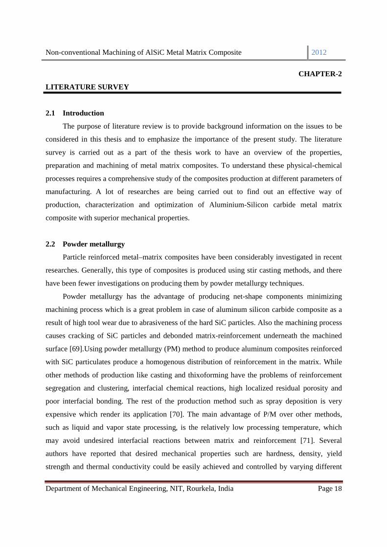
2.1 Introduction
The purpose of literature review is to provide background information on the issues to be
considered in this thesis and to emphasize the importance of the present study. The literature
survey is carried out as a part of the thesis work to have an overview of the properties,
preparation and machining of metal matrix composites. To understand these physical-chemical
processes requires a comprehensive study of the composites production at different parameters of
manufacturing. A lot of researches are being carried out to find out an effective way of
production, characterization and optimization of Aluminium-Silicon carbide metal matrix
composite with superior mechanical properties.
2.2 Powder metallurgy
Particle reinforced metal–matrix composites have been considerably investigated in recent
researches. Generally, this type of composites is produced using stir casting methods, and there
have been fewer investigations on producing them by powder metallurgy techniques.
Powder metallurgy has the advantage of producing net-shape components minimizing
machining process which is a great problem in case of aluminum silicon carbide composite as a
result of high tool wear due to abrasiveness of the hard SiC particles. Also the machining process
causes cracking of SiC particles and debonded matrix-reinforcement underneath the machined
surface [69].Using powder metallurgy (PM) method to produce aluminum composites reinforced
with SiC particulates produce a homogenous distribution of reinforcement in the matrix. While
other methods of production like casting and thixoforming have the problems of reinforcement
segregation and clustering, interfacial chemical reactions, high localized residual porosity and
poor interfacial bonding. The rest of the production method such as spray deposition is very
expensive which render its application [70]. The main advantage of P/M over other methods,
such as liquid and vapor state processing, is the relatively low processing temperature, which
may avoid undesired interfacial reactions between matrix and reinforcement [71]. Several
authors have reported that desired mechanical properties such are hardness, density, yield
strength and thermal conductivity could be easily achieved and controlled by varying different

Non-conventional Machining of AlSiC Metal Matrix Composite 2012
Department of Mechanical Engineering, NIT, Rourkela, India Page 19
processing routes like compaction pressure, sintering temperature of powder metallurgy method
[43, 72]
In Powder metallurgy method by increasing sintering temperature above the melting point
of matrix metal not only breaks oxidation layer and fills porosity but also increases
micromechanical properties [69]. Ice quenching of AlSiC MMC followed by artificial ageing for
6 h resulted in better mechanical properties of matrix alloy and its composites [73]. In addition,
P/M allows a great degree of freedom in tailoring the microstructure (e.g., volume fraction, size
and morphology of the reinforcement) [74].
2.3 Electrical Discharge Machining (EDM)
EDM has been a mainstay of manufacturing for more than six decades, providing unique
capabilities to machine “difficult-to-machine” materials with desire shape, size, and required
dimensional accuracy. Its distinctive attribute of using thermal energy to machine electrically
conductive materials, regardless of hardness, has been an advantage in the manufacturing of
mould, die, surgical, automotive and aeronautic components. It is essential especially in the
machining of super tough, hard and electrically conductive materials such as the new space age
alloys. It is better than other machining processes in terms of precision, quality characteristics
and the fact that hardness and stiffness of a workpiece material is not important for the material
removal. Though EDM has become an established technology, and commonly used in
manufacturing of mechanical works, yet its low efficiency and poor surface finish have been the
vital matter of concern. Hence, the investigations and improvements of the process are still going
on, since no such process exists, which could successfully replace the EDM.
2.3.1 Mechanism of Material Removal in EDM
Electrical discharge machining is the most widely-used non-conventional machining
process. Despite the fact that the mechanism of material removal of EDM process is not yet
completely understood and is still debatable, the most widely established principle is the
conversion of electrical energy it into thermal energy through a series of discrete electrical
discharges occurring between the electrode and workpiece immersed inside a dielectric medium
and separated by a small gap. Material is removed from the workpiece by localized melting and
even vaporization of material. The sparks are created in between two electrodes in presence of

Non-conventional Machining of AlSiC Metal Matrix Composite 2012
Department of Mechanical Engineering, NIT, Rourkela, India Page 20
dielectric liquid. A simple explanation of the erosion process due to the discharge is presented in.
There is no mechanical contact between the electrodes (held at a small distance) and a high
potential difference is applied across them.
The material removal mechanisms are been reported differently by many authors. Singh
and Ghosh [75] showed that the electrostatic forces and stress distribution acting on the cathode
electrode were the major causes of metal removal for short pulses. Gadalla and Tsai [76]
elucidated the material removal of WC-Co composite to the melting and evaporation of
disintegrated Co followed by the dislodging of WC gains, which have a lower electrical
conductivity on the other hand, Lee and Lau [77] argued that thermal spalling as well contributes
to the mechanism of material removal during the sparking of composite ceramics due to the
physical and mechanical properties promotes abrupt temperature gradients from normal melting
and evaporation.
2.3.2 EDM process parameters
As per the discharge phenomena explained earlier, some of the important process
parameters which influence the responses are:
Discharge current (Ip): It is the most important machining parameter in EDM because it
relates to power consumption of power while machining. The current increases until it reaches a
preset level which is expressed as discharge current.
Discharge voltage (V): It is the open circuit voltage which is applied between the electrodes.
The discharge voltage de-ionizes the dielectric medium, which depends upon the electrode gap
and the strength of the dielectric, prior to the flow of current. Once the current flow starts, the
open circuit voltage drops and stabilizes the electrode gap. It is a vital factor that influences the
spark energy,
Pulse-on time (Ton): It is the time during which actual machining takes place and it is
measured in µs. In each discharge cycle, there is a pulse on time and pause time/Pulse off time,
and the voltage between the electrode and workpiece is applied during Ton duration. The longer
the pulse duration higher will be the spark energy that creates wider and deeper crated.
Pulse-off time or pause time (Toff ): In a cycle, there is a pulse off time or pause time during
which the supply voltage is cut off as a consequence the Ip diminisisses to zero. It is also the
duration of time after which the next spark is generated and is expressed in µs analogous to Ton.
Non-conventional Machining of AlSiC Metal Matrix Composite 2012
Department of Mechanical Engineering, NIT, Rourkela, India Page 21
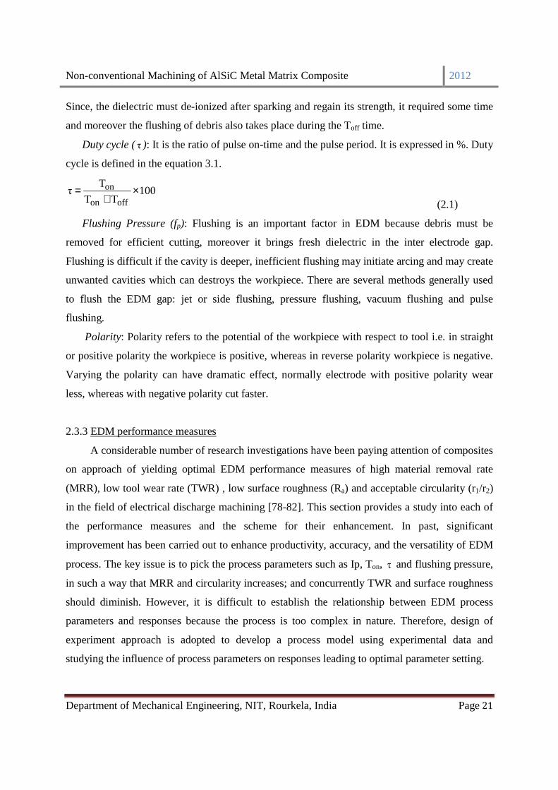
Since, the dielectric must de-ionized after sparking and regain its strength, it required some time
and moreover the flushing of debris also takes place during the Toff time.
Duty cycle (τ ): It is the ratio of pulse on-time and the pulse period. It is expressed in %. Duty
cycle is defined in the equation 3.1.
100TT
Tτ
offon
on ×+
= (2.1)
Flushing Pressure (fp): Flushing is an important factor in EDM because debris must be
removed for efficient cutting, moreover it brings fresh dielectric in the inter electrode gap.
Flushing is difficult if the cavity is deeper, inefficient flushing may initiate arcing and may create
unwanted cavities which can destroys the workpiece. There are several methods generally used
to flush the EDM gap: jet or side flushing, pressure flushing, vacuum flushing and pulse
flushing.
Polarity: Polarity refers to the potential of the workpiece with respect to tool i.e. in straight
or positive polarity the workpiece is positive, whereas in reverse polarity workpiece is negative.
Varying the polarity can have dramatic effect, normally electrode with positive polarity wear
less, whereas with negative polarity cut faster.
2.3.3 EDM performance measures
A considerable number of research investigations have been paying attention of composites
on approach of yielding optimal EDM performance measures of high material removal rate
(MRR), low tool wear rate (TWR) , low surface roughness (Ra) and acceptable circularity (r1/r2)
in the field of electrical discharge machining [78-82]. This section provides a study into each of
the performance measures and the scheme for their enhancement. In past, significant
improvement has been carried out to enhance productivity, accuracy, and the versatility of EDM
process. The key issue is to pick the process parameters such as Ip, Ton, τ and flushing pressure,
in such a way that MRR and circularity increases; and concurrently TWR and surface roughness
should diminish. However, it is difficult to establish the relationship between EDM process
parameters and responses because the process is too complex in nature. Therefore, design of
experiment approach is adopted to develop a process model using experimental data and
studying the influence of process parameters on responses leading to optimal parameter setting.

Non-conventional Machining of AlSiC Metal Matrix Composite 2012
Department of Mechanical Engineering, NIT, Rourkela, India Page 22
Khan et al. [83] discuss the performance about the shape configuration of the electrode.
The maximum MRR was found for round electrodes followed by square, triangular and diamond
shaped electrodes. However, the highest EWR were found for the diamond shaped electrodes.
Subsequently, Khan [84] reported overall performance comparison of copper and brass
electrodes and observed that the highest MRR was observed during machining of aluminium
using brass electrodes. Comparatively low thermal conductivity of brass as an electrode material
does not allow the absorption of much heat energy, and most of the heat is utilized in the
removal of material from aluminium workpiece at a low melting point but more wear occurred
than copper. Copper has high melting point and conductivity than brass.
Karthikeyan et al. [31] developed mathematical models for optimizing EDM characteristics
such as the MRR, TWR and the surface roughness on aluminium silicon carbide particulate
composites, using full factorial design. The process parameters taken in to consideration were Ip,
Ton and the percent volume fraction of SiC present in LM25 aluminium matrix. Dhar et al. [85]
estimated the effect of Ip, Ton, and V on MRR, TWR on EDM of Al-4Cu-6Si alloy-10 wt. %
SiCP composites. Using three factors, three level full factorial designs, a second order non-linear
mathematical model has been developed for establishing the relationship among machining
parameters. It was revealed that the MRR and TWR increase with increase in Ip and Ton. El-
Taweel [86] investigated the correlation of process parameters in EDM of CK45 steel with Al-
Cu-Si-TiC composite produced using powder metallurgy technique and evaluated MRR and
TWR. It is found that such electrodes are more sensitive to Ip and Ton than conventional
electrodes. To achieve maximum MRR and minimum TWR, the process parameters are
optimized and on experimental verification the results are found to be in good agreement.
Dvivedi et al. [87] identified the machining performance in terms of MRR and TWR by
obtaining an optimal setting of process parameters (Ton, Toff, Ip, and fp) during EDM of Al
6063 SiCp metal matrix composite. It was revealed that Ip is predominant on MRR than other
significant parameters. MRR increases with increasing Ip and Ton up to an optimal point and
then dropped. Wang and Lin [88] investigated the feasibility and optimization of EDM for
inspecting the machinability of W/Cu composites using the Taguchi method utilizing L18
orthogonal table to obtain the Ip, Ton, τ and V in order to explore the MRR and TWR. Chiang
[89] had explained the influences of Ip, Ton, Tau and voltage on the responses; MRR and
electrodes wear and surface roughness. The experiments were planned according to a CCD on

Non-conventional Machining of AlSiC Metal Matrix Composite 2012
Department of Mechanical Engineering, NIT, Rourkela, India Page 23
Al2O3+TiC workpiece and the influence of parameters and their interactions were investigated
using ANOVA. A mathematical model was developed and claimed to fit and predict MRR
accurately with a 95% confidence. The main two significant factors affecting the response were
Ip andτ .
2.4 Multi-objective optimization
In composites, materials are combined in such a way as to enable us to make better use of
their virtues while minimizing to some extent the effects of their deficiencies. This process of
optimization can release a designer from the constraints associated with the selection and
manufacture of MMCs. He can make use of tougher and lighter materials, with properties that
can be tailored to suit particular design requirements. And because of the ease with which
complex shapes can be manufactured, the complete rethinking of an established design in terms
of composites can often lead to both cheaper and better solutions. So, in order to get the best
quality characteristics, the material and machine parameters influencing the machining process
need to be optimized. The design of experiment approach, notably Taguchi method, is suitable
for optimization of single response only. In practice, multiple responses are desired to be
simultaneously optimized. It is difficult to find a single optimal combination of process
parameters for multiple performance characteristics since process parameters influence them
differently. Hence, there is a need for a multiple response optimization method to arrive at the
solutions to this problem. Classical methods for solving multiple objective optimization problem
use weighted functions for transforming the multiple objectives into an equivalent single
objective leading to trading off of responses. The best parameter combination may be far away
from the real optimal parameters. Moreover, the classical methods fail when the function
becomes discontinuous. To alleviate this problem, a number of multiple response optimization
methodologies like fuzzy logic, grey relational analysis and artificial neural network have been
proposed to machining of composites [60, 90-92]. Chen at al. [97] optimized the process
parameters while machining tungsten in a wire electrical discharge machining set up using
combined Taguchi’s method with back-propagation neural network. Haq et al. [98] optimized
multiple responses in drilling of AlSiC MMC by integrating Taguchi’s method with grey
relational analysis. Aggarwal et al. [99] optimized the machining parameters of CNC turned
parts combining principal component analysis with Taguchi method. In most of the approaches,

Non-conventional Machining of AlSiC Metal Matrix Composite 2012
Department of Mechanical Engineering, NIT, Rourkela, India Page 24
the responses are considered to be uncorrelated. In practice, the responses are not independent
rather they are correlated and conflicting in nature. Therefore, it is vital to study the correlation
of responses before applying any method for converting multiple responses into an equivalent
single response. In this study, principal component analysis (PCA) is applied on responses to
obtain uncorrelated principal components (PCs). Further, the experimental data are also
subjected to uncertainty and impreciseness. Therefore, fuzzy inference system is adopted to
convert multiple responses into a single response known as multi-performance characteristic
index (MPCI) so that uncertainty and impreciseness can be taken into account [96]. The rule base
for fuzzy inference system can be easily developed in practice using the expertise of shop floor
managers or tool engineers. In recent times, a new trend has been introduced to hybridize the
features of two or more than two techniques to take advantage of the potential of each technique
and shrink their disadvantages. Such technique with combined features is called as hybrid
modeling technique. So PCA-Fuzzy inference system is a hybrid optimization technique for
multi-responses optimization.
2.5 Conclusion
Exhaustive literature survey focused into various past works carried in the production of
MMCs. The investigations of several researchers have been thoroughly studied and their
conclusive findings have been recorded concerning the processing and machining of composites
through various routes. Powder metallurgy and Electro Discharge Machining are considered for
the composite production. Machining parameters affecting quality characteristics in the
machining process is thoroughly studied. Productivity is constantly a matter of concern with a
high level of accuracy for any process; rather it is the driver of economic growth of industry.
Therefore, it is always desirable to have machining with maximum MRR, minimal TWR and
minimum surface roughness along with better circularity. At the end of this chapter various
multi-responses optimization methods has been examined. A hybrid approach combining both
Principal component analysis and Fuzzy inference system with Taguchi methodology is
suggested to predict the optimal parameter setting for the machining process.
******
Non-conventional Machining of AlSiC Metal Matrix Composite 2012
Department of Mechanical Engineering, NIT, Rourkela, India Page 25
CHAPTER-3
EXPERIMENTAL DETAILS

Non-conventional Machining of AlSiC Metal Matrix Composite 2012
Department of Mechanical Engineering, NIT, Rourkela, India Page 26
CHAPTER-3
EXPERIMENTAL DETAILS
3.1 Introduction
This chapter describes the experimental procedure adopted in the present project-work. A
detailed report is also provided on the characterization of raw materials used for fabrication of
the MMC test specimens. The chapter houses a description of the detailed step-wise methods
adopted for fabrication of the test specimens, the thermal treatment imparted the Mechanical and
electrical testing carried out. Micrographs are generated through Scanning Electron Microscopy
for the detailed analysis of reinforcement distribution in the matrix. Then machining is
performed on the prepared MMC to study the quality characteristics. For the sake of clarity and
visual basics, photographs of equipments / instruments that have been used in this work are also
presented according to their place of use.
3.2 Material
Commercial grade Aluminium alloy powders were obtained from Loba Chemie Pvt. Ltd.,
India. The SiC particulates were obtained from the market. The specifications/composition
obtained is presented below.
3.2.1 Aluminium Alloy:
The aluminium alloy contains Al-99.7%, Fe-0.17%, Mg-0.0016%, Zn-0.0053%, Cu-
0.00159% of other materials. And Particle sizes -120 mesh (~20 µm).
3.2.2 SiC particulates:
SiCp is obtained from the open market with assay 99% (metal basis) and Particle size: 300
mesh (50 µm), 400 mesh (37 µm)
3.2.3 Pre-treatment of SiC particulates
The SiCp is heated to a temperature of 7000C in a muffle furnace (Wild Barfield furnace,
max. temp. 13500C, Made in England) in the presence of air and kept at the temperature for sixty
minutes prior to using it for fabrication of the MMC samples. This is done in order to form a thin
Non-conventional Machining of AlSiC Metal Matrix Composite 2012
Department of Mechanical Engineering, NIT, Rourkela, India Page 27
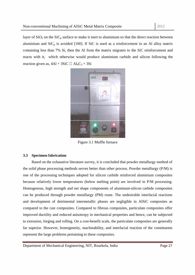
layer of SiO2 on the SiCp surface to make it inert to aluminium so that the direct reaction between
aluminium and SiCp is avoided [100]. If SiC is used as a reinforcement in an Al alloy matrix
containing less than 7% Si, then the Al from the matrix migrates to the SiC reinforcement and
reacts with it, which otherwise would produce aluminium carbide and silicon following the
reaction given as, 4Al + 3SiC ⇔Al4C3 + 3Si
Figure 3.1 Muffle furnace
3.3 Specimen fabrication
Based on the exhaustive literature survey, it is concluded that powder metallurgy method of
the solid phase processing methods serves better than other process. Powder metallurgy (P/M) is
one of the processing techniques adopted for silicon carbide reinforced aluminium composites
because relatively lower temperatures (below melting point) are involved in P/M processing.
Homogenous, high strength and net shape components of aluminum-silicon carbide composites
can be produced through powder metallurgy (PM) route. The undesirable interfacial reactions
and development of detrimental intermetallic phases are negligible in AlSiC composites as
compared to the cast composites. Compared to fibrous composites, particulate composites offer
improved ductility and reduced anisotropy in mechanical properties and hence, can be subjected
to extrusion, forging and rolling. On a cost-benefit scale, the particulate composites are generally
far superior. However, homogeneity, machinability, and interfacial reaction of the constituents
represent the large problems pertaining to these composites.

Non-conventional Machining of AlSiC Metal Matrix Composite 2012
Department of Mechanical Engineering, NIT, Rourkela, India Page 28
3.4 Powder metallurgy method
The MMC test specimens are fabricated by powder metallurgy route using ball mill
mixing, solid state sintering and heat treatment.
3.4.1 Mixing of powders
The MMC test specimens are fabricated by the powder metallurgy route adopting the usual
mixing and solid state sintering. 90% and 85 % Aluminium powder and 10% and 15 % SiCp by
weight are mixed for fabricating the composite. 300 and 400 mesh SiCp each of 10 and 15 %
were weighted and mixed. Total four categories of mixture were prepared (90% Al+ 10 % SiC
(300 mesh), 90% Al+ 10 % SiC (400 mesh), 85% Al+ 15 % SiC (300 mesh), 85% Al+ 15 % SiC
(400 mesh)). Blending is carried out in ball planetary mill (Model-PULVERISETTE-5, Make-
FRITSCH, Germany) shown in figure 3.2. It consists of two cylindrical containers of chrome
steel inside which 10 balls made up of chrome steel of sizes 10 mm. The blending machine
continues rotations for 3 lakh revolutions to reach a homogenous distribution of the
reinforcement in the mixture.
Figure 3.2 Ball planetary mill
3.4.2 Compaction of the powder mix
About 10gms of the powder mixture was taken adopting a method of coning and quartering
for compaction in a cold uniaxial press in a metallic die-punch arrangement.

Non-conventional Machining of AlSiC Metal Matrix Composite 2012
Department of Mechanical Engineering, NIT, Rourkela, India Page 29
3.4.3 Cold uniaxial pressing
The powder sample is pressed in the cold uniaxial pressing machine (Make-SOILLAB
,Type-Hydraulic ) to render the green circular test samples of 25mm outer diameter applying a
load of 18 ton, which accounted 3600 bar pressure. A stainless steel die of 25 mm internal
diameter was used for this purpose. To allow the powder to flow freely and to prevent the
specimen from sticking on to the walls, stearic acid was used as a lubricant that was applied to
the walls of the die and punch. The pressing machine is shown in figure 3.3.
Figure 3.3 Cold uniaxial pressing machine
3.4.4 Sintering of the green samples
The green samples are carefully baked at an elevated temperature in a controlled
atmosphere environment but just below the melting point of major constituent for a sufficient
time. It is carried out in horizontal tubular furnace (Make-Naskar and Co., Type- Vacuum and
Control Atmosphere) in an atmosphere of argon at pressure of 1 bar as shown in figure 3.4. A
batch of eight samples from each of the two mixtures containing 10, 15 % SiC were sintered at
two different temperatures 600 and 6500 C respectively. The time of holding was one hour. The
high temperature sintering process cause the aluminum surrounded by the oxide layer in the
particle to melt and expand in volume to rupture the oxide envelope surrounding it and makes
contact with melted aluminum leaking from nearby particles and welding take place. The oxide
layer broke into small shell fragments impeded in the aluminum matrix restricting the movement
of dislocation and increase strength. The presence of silicon carbide particles also hinders the
aluminum melt from one particle to join melt from another. So increasing silicon carbide content

Non-conventional Machining of AlSiC Metal Matrix Composite 2012
Department of Mechanical Engineering, NIT, Rourkela, India Page 30
increase the sintering temperature needed to achieve high strength composite. Then furnace is
allowed to cool to room temperature for a span of 24 hours. Then, the pallets are removed from
the furnace and kept in a desiccators containing concentrated H2SO4. The average diameter and
thickness of pallets are 22 mm and 9 mm.
Figure 3.4 Horizontal tubular furnace
3.4.5 Heat treatment
Heat treatment refines the grain structure inside a material part, thus increasing its
mechanical properties.
3.4.5.1. Quenching
The samples were then solution heat treated at 500 0 C for one hour and then quenched in
iced water. Quenching was carried in a heat treatment furnace (Local made) shown in figure 3.4.
Figure 3.5 Heat treatment furnace
Non-conventional Machining of AlSiC Metal Matrix Composite 2012
Department of Mechanical Engineering, NIT, Rourkela, India Page 31
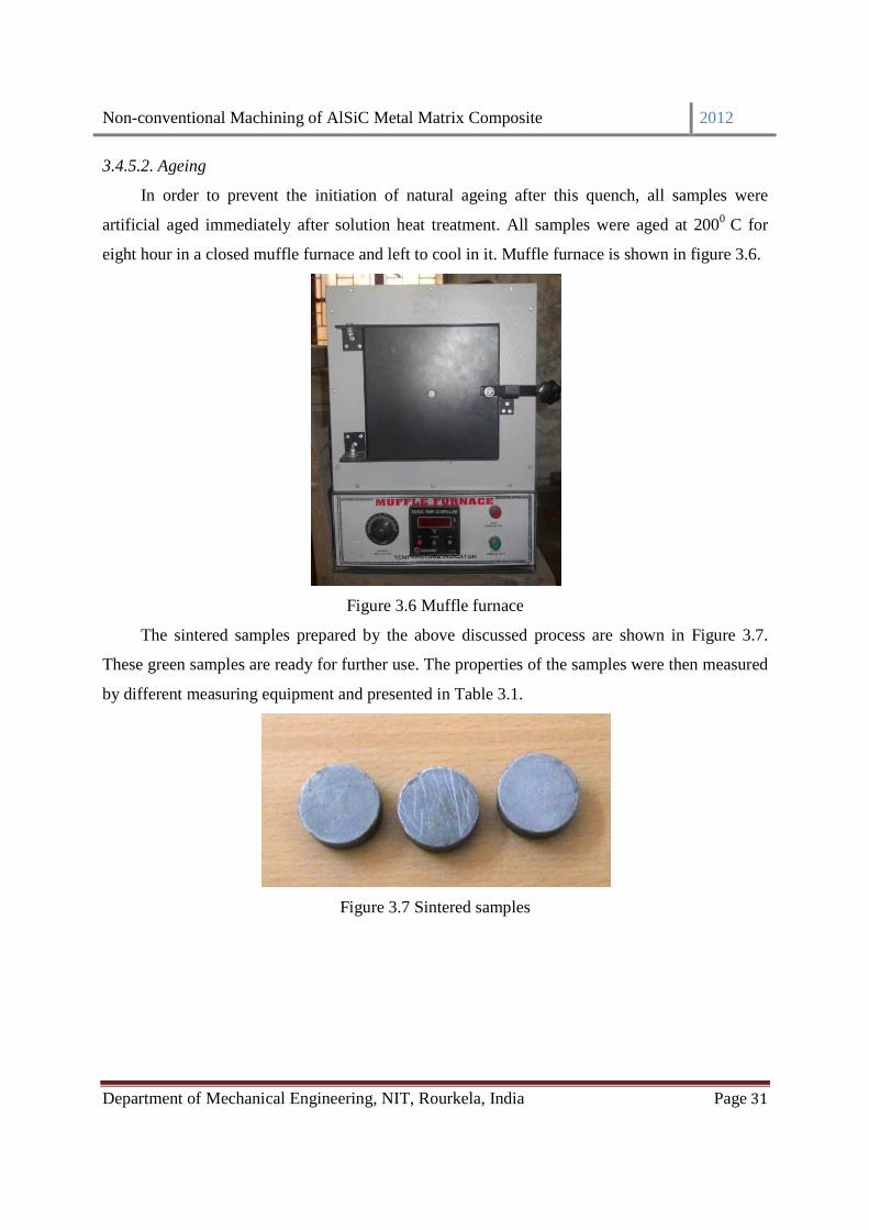
3.4.5.2. Ageing
In order to prevent the initiation of natural ageing after this quench, all samples were
artificial aged immediately after solution heat treatment. All samples were aged at 2000 C for
eight hour in a closed muffle furnace and left to cool in it. Muffle furnace is shown in figure 3.6.
Figure 3.6 Muffle furnace
The sintered samples prepared by the above discussed process are shown in Figure 3.7.
These green samples are ready for further use. The properties of the samples were then measured
by different measuring equipment and presented in Table 3.1.
Figure 3.7 Sintered samples

Non-conventional Machining of AlSiC Metal Matrix Composite 2012
Department of Mechanical Engineering, NIT, Rourkela, India Page 32
3.5 Results & discussions
3.5.1 XRD analysis
To confirm the certainty of the constituents present in the blended powder of the specimen,
supplied matrix element (aluminum) and reinforcement element (silicon carbide), X-Ray
diffraction analysis is carried out using XRD instrument supplied by XRD -PHILIPS Analytical
Ltd. PW 3040 as shown in figure 3.8. After the XRD analysis, the peaks obtained is shown in
Figure 3.9 confirms the presence of only two phases viz., Al and SiC crystals. The data obtained
from XRD of above elements (counts at different angles, 2θ and d-spacing,0
A ) are analyzed using
Xpert Highscore software (Philips). From the XRD graph (Figure 3.9), it is shown that
aluminium is 99.7% pure and the rest contains aluminium alloys like aluminium silicon,
aluminium manganese and aluminium titanium. XRD test is also carried out on silicon carbide of
both mesh sizes. It is found that SiC contains mostly moissanite-6H i.e. SiC and very little traces
of Paladium Oxide and Al2Si3O12. Again XRD analysis is performed to confirm the constituents
present in the blended powder of the specimen. It was found that the specimen was free from
chrome steel crystals expected from blending in a chrome steel crucible. These results confirm
the suitability of the sample pallets in respect of uniform distribution of particles and confirm that
they are precisely accurate for further analysis.
Figure 3.8 XRD instrument

Non-conventional Machining of AlSiC Metal Matrix Composite 2012
Department of Mechanical Engineering, NIT, Rourkela, India Page 33
20 40 60 80-500
0
500
1000
1500
2000
2500
3000
3500
4000
4500
5000
5500
(α,θ
,λ)
(θ,ϕ
)
(α,ϕ
)
(θ,λ
)
(α,φ
)
(α,λ
,φ)
(α,θ
,λ,ϕ
,ο,φ
)
(λ)
(θ)(θ
)(θ
) (α,σ
,θ,δ
)
(α,σ
,θ,δ
)
(θ)
(θ)
(θ)(α
,ψ,θ
,δ)
(ρ,θ
)(ρ
,δ,θ
)
(θ,λ
,δ) (θ
)
(θ)
(θ)
(θ)
(θ,∆
,δ)
(θ)
(θ)
(θ)
(θ)
(θ)
(θ)(θ
) (θ,δ
)
(θ,δ
)
(θ,∆
,δ)
(θ,δ
)
(θ,∆
,δ)
(α,β
)
(α,η
)
(α,β
,χ,η
)
coun
ts (
A0 )
Position [ 02 Theta ]
Aluminium Al + SiC (10%) Al + SiC (15%) SiC (300 Mesh) SiC (400 Mesh)
(α,β
,χ,η
) (θ,∆
,δ)
α=Al
β=AlSi
χ=Al0.27
Mn0.73
η=Al2Ti
θ=SiC
∆=PdO2
δ=(Fe2Mg
0.4)Al
2Si
3O
12
ο=SiC(Moissanite)
ψ=Pd21
Sm10
σ=Ni17
Al13.9
Si5.1
O48
φ=AlN
ρ=Sapphirine
ϕ=Al0.5
Fe3Si
0.5
λ=Fe3Al
2(SiO
4)
3
Figure 3.9 The XRD graphs
3.5.2 Density
The actual densities of the samples are obtained through water immersion method shown in
Table 3.1. From Table 3.1, it is observed that maximum of 67.24% increase in density occurs
after sintering the green samples due to filling up of the voids between particles with melted
aluminum. Theoretically, the densities of the composites are measured using the following
relation.
WW
1
SiC
SiC
Al
AlC
ρ+
ρ
=ρ
(4.1)

Non-conventional Machining of AlSiC Metal Matrix Composite 2012
Department of Mechanical Engineering, NIT, Rourkela, India Page 34
where
Cρ - Composite density, g/mm3
AlW - Weight fraction of aluminium
Alρ - Density of aluminium (0.00262 g/mm3)
SiCW - Weight fraction of silicon carbide
SiCρ - Density of silicon carbide (0.0032 g/mm3)
Using above equation, the theoretical density of the MMC is found to be 0.00268 g/mm3. The
average actual density is found to be 0.00230g/mm3. The difference in density is attributed to
presence of voids in the samples.
3.5.3 Hardness
Hardness of the green and sintered samples is measured by the equipment Vickers hardness
measuring machine (Leco Vickers Hardness Tester, USA Model: LM 2481T) in figure
3.10.From Table3.1, it is observed that hardness increases by at least 40% after sintering. The
average hardness for samples is found to be 56.61 and 73.08 VHN for SiC weight percentage of
10 and 15 respectively whereas hardness for aluminiumis 15 VHN. Figure 3.11 shows that
average hardness of samples increases as mesh size increases and wt. % of SiC increases.
However, mesh size of SiC causes significant improvement in the hardness of the MMC.
Figure 3.10 Vickers hardness measuring machine

Non-conventional Machining of AlSiC Metal Matrix Composite 2012
Department of Mechanical Engineering, NIT, Rourkela, India Page 35
Figure 3.11 Variation of hardness with % of SiC
3.5.4 Conductivity
Conductivity of MMC is measured by digital electrical conductivity measuring device
(Sigmascope SMP 10) as in Figure 3.12 using aluminium plating at room temperature. From
Table 3.1, it can be noticed that conductivity decreases when silicon carbide percentage in the
sample increases from 10 to 15% due to resistive nature for electricity conduction of SiCp.
However, the conductivity of the samples is enough to facilitate electrical discharge machining
on samples because the machining process needs minimum conductivity of work piece as 0.01
S/cm [101].
Figure 3.12 Digital electrical conductivity measuring device
50
55
60
65
70
75
10 15
300 Mesh
400 MeshH
ard
nes
s
wt. % of SiC

Non-conventional Machining of AlSiC Metal Matrix Composite 2012
Department of Mechanical Engineering, NIT, Rourkela, India Page 36
Table 3.1 Properties of the samples
Density (g/mm3) Hardness (VHN)
%
SiC
Mesh
Size
Before
Sintering
After
Sintering
& HT
%
increase
Before
Sintering
After
Sintering
& HT
%
increase
Electrical
Conductivity
(S/cm)
10 300 0.001801 0.00182 1.05 47.6 58.9 23.74 1.11
10 300 0.001745 0.00178 2.00 48.7 51.0 4.72 1.11
10 300 0.001730 0.00186 7.51 48.1 50.3 4.57 1.25
10 300 0.001716 0.00185 7.80 45.3 59.3 30.91 1.11
10 400 0.001743 0.00248 42.28 53.8 58.5 8.74 1.25
10 400 0.001749 0.00221 26.35 50.3 61.4 22.07 1.43
10 400 0.001728 0.00280 62.03 51.4 53.0 3.18 1.25
10 400 0.001726 0.00230 33.25 51.9 60.5 16.57 1.25
15 300 0.001762 0.00290 19.75 57.2 68.3 19.41 1.00
15 300 0.001773 0.00254 61.30 58.1 73.2 26.00 0.91
15 300 0.001752 0.00244 21.57 57.8 73.1 26.47 0.91
15 300 0.001768 0.00223 34.61 60.1 75.0 24.79 1.00
15 400 0.001734 0.00211 67.24 60.6 76.5 26.24 0.91
15 400 0.001726 0.00286 47.16 58.5 71.7 22.56 1.00
15 400 0.001720 0.00213 41.86 59.8 74.2 24.08 0.91
15 400 0.001710 0.00238 30.40 61.8 72.6 17.48 1.11
HT- Heat treatment
3.5.5 Microstructure analysis
Microstructure examinations are carried out to investigate of distribution of the silicon
carbide particles in the composite. Samples having 10 and 15 weight percentage of silicon
carbide are examined at both green and sintered state. The samples are polished using emery
paper (1000 and 1500 grit size) and finally etched using acetone. The microstructures of samples
are studied using a Scanning Electron Microscope (SEM) (JEOL JSM 6480 LV) shown in Figure
3.13.

Non-conventional Machining of AlSiC Metal Matrix Composite 2012
Department of Mechanical Engineering, NIT, Rourkela, India Page 37
Figure 3.13 Scanning Electron Microscope
Micrographs of samples taken before sintering (green samples) are shown in Figure 3.14. It
is observed that silicon carbide particles are homogeneously distributed in the matrix. Some
clustering of the reinforcement is found in both the micrographs and increases as the percentage
of reinforcement and mesh size increases. Figure 3.15 shows the micrographs of the sintered
samples. It can be observed that silicon carbide particles are covered by melted aluminum
particles. In spite of compaction and sintering, presence of voids in the matrix cannot be avoided.
More number of voids of larger size is observed in the samples of 10% weight percentage of
silicon carbide as compared to 15% weight percentage of silicon carbide. It was also observed
that voids are more pronounced when size of silicon carbide is decreased.
(a) (b)
Figure 3.14 Micrographs showing the distribution of the reinforcement in the composite (green
samples) (a) 10% SiC (300 Mesh size) (b) 15% SiC (400 Mesh size)
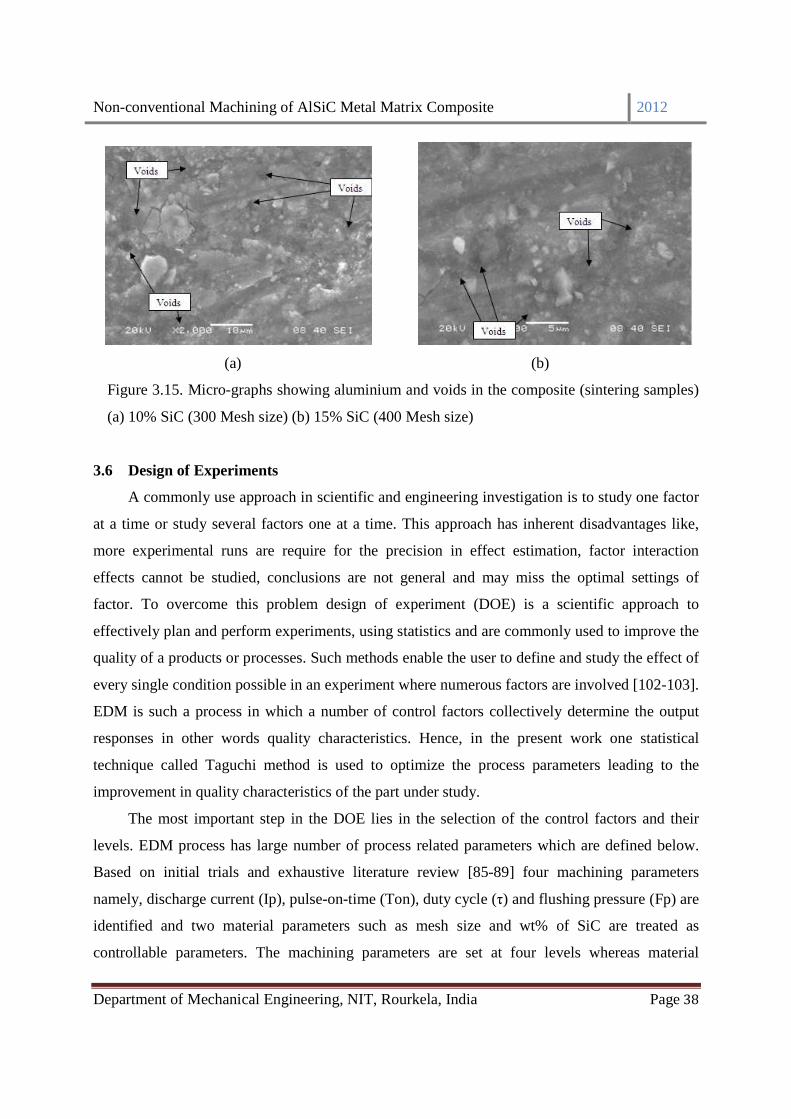
Non-conventional Machining of AlSiC Metal Matrix Composite 2012
Department of Mechanical Engineering, NIT, Rourkela, India Page 38
(a) (b)
Figure 3.15. Micro-graphs showing aluminium and voids in the composite (sintering samples)
(a) 10% SiC (300 Mesh size) (b) 15% SiC (400 Mesh size)
3.6 Design of Experiments
A commonly use approach in scientific and engineering investigation is to study one factor
at a time or study several factors one at a time. This approach has inherent disadvantages like,
more experimental runs are require for the precision in effect estimation, factor interaction
effects cannot be studied, conclusions are not general and may miss the optimal settings of
factor. To overcome this problem design of experiment (DOE) is a scientific approach to
effectively plan and perform experiments, using statistics and are commonly used to improve the
quality of a products or processes. Such methods enable the user to define and study the effect of
every single condition possible in an experiment where numerous factors are involved [102-103].
EDM is such a process in which a number of control factors collectively determine the output
responses in other words quality characteristics. Hence, in the present work one statistical
technique called Taguchi method is used to optimize the process parameters leading to the
improvement in quality characteristics of the part under study.
The most important step in the DOE lies in the selection of the control factors and their
levels. EDM process has large number of process related parameters which are defined below.
Based on initial trials and exhaustive literature review [85-89] four machining parameters
namely, discharge current (Ip), pulse-on-time (Ton), duty cycle (τ) and flushing pressure (Fp) are
identified and two material parameters such as mesh size and wt% of SiC are treated as
controllable parameters. The machining parameters are set at four levels whereas material

Non-conventional Machining of AlSiC Metal Matrix Composite 2012
Department of Mechanical Engineering, NIT, Rourkela, India Page 39
parameters are set at two levels. The details of parameters and their levels are shown in Table 3.2
as significant factors and hence are selected to study their influence on output responses.
Table 3.2 Control parameters and their levels.
3.7 Taguchi experimental design
Taguchi experimental design that extensively uses orthogonal arrays is an efficient tool for
improving process/product quality with relatively less number of experimental runs. The method
can optimize performance characteristics through determination of best parameter settings and
reduces the sensitivity of the system performance to sources of variation. Orthogonal arrays
provide a set of well-balanced experiments with less number of experimental runs. A mixed
orthogonal array is formed by taking four machining parameters each at four levels and two
material parameters each at two levels. The appropriate array for this case is L16 Orthogonal
array is shown in Table 3.3.
Symbol Control parameters Levels
1 2 3 4
A Discharge current (A) 1 3 5 7
B Pulse-on-time (µS) 100 200 300 400
C Duty cycle (%) 80 85 90 95
D Flushing pressure (bar) 0.9806 1.9613 2.1419 3.9226
E SiC (wt%) 10 15
F Mesh size(particle size in
micron) 300 (50) 400 (37)

Non-conventional Machining of AlSiC Metal Matrix Composite 2012
Department of Mechanical Engineering, NIT, Rourkela, India Page 40
Table 3.3 L16 Orthogonal array
Exp. No Factors
A B C D E F
1 1 1 1 1 1 1
2 1 2 2 2 1 2
3 1 3 3 3 2 1
4 1 4 4 4 2 2
5 2 1 2 3 2 2
6 2 2 1 4 2 1
7 2 3 4 1 1 2
8 2 4 3 2 1 1
9 3 1 3 4 1 2
10 3 2 4 3 1 1
11 3 3 1 2 2 2
12 3 4 2 1 2 1
13 4 1 4 2 2 1
14 4 2 3 1 2 2
15 4 3 2 4 1 1
16 4 4 1 3 1 2
3.8 Electrical discharge machining process
The study intends to investigate the effect process parameters such as discharge current
(Ip), pulse-on-time (Ton), duty cycle (τ) and flushing pressure (Fp) on material removal rate
(MRR), tool wear rate (TWR), surface roughness (Ra) and circularity (r1/r2). The equipment used
to perform the experiments is an Electronica Electraplus PS 50ZNC Die Sinking Fuzzy Logic
based Electrical Discharge Machine shown in Figure 3.16. Commercial grade EDM oil (specific
gravity = 0.763, freezing point= 94˚C) is used as dielectric fluid. A lateral flushing system is
employed for effective flushing of machining debris from the working gap region. To get more
accurate results, each experiment is conducted for one hour. The work piece material used is
aluminium silicon carbide metal matrix composite. Straight polarity is adopted due to high MRR.
A cylindrical copper tool with a diameter of 12 mm is used as a tool electrode (negative polarity)

Non-conventional Machining of AlSiC Metal Matrix Composite 2012
Department of Mechanical Engineering, NIT, Rourkela, India Page 41
and workpiece material (positive polarity). Density of copper tool taken is 0.00896 kg/m3 Shown
in Figure 3.17. The photos of the machined (drilled) AlSiC MMCs are shown in Figure 3.18. The
MRR is calculated using the volume loss from the work piece as cubic millimeter per minute.
During the electric discharge, some of the discharge energy applied to the tool produces a crater
in the tool material. TWR is expressed as the volumetric loss of tool per unit time. The weight
loss is measured by an electronic balance weight measuring machine (Sansui (Vibra), Shinko
Denshi Co. Ltd. Made in Japan) with a least count of 0.001g and shown in Figure 3.19.
Figure 3.16 Electrical Discharge Machine Figure 3.17 Copper tool (electrode)
Figure 3.18 Machined AlSiC composites

Non-conventional Machining of AlSiC Metal Matrix Composite 2012
Department of Mechanical Engineering, NIT, Rourkela, India Page 42
Figure 3.19 Electronic balance weight measuring machine
3.8.1 Material removal rate (MRR)
MRR is expressed as,
T
WWMRR
w
fi
ρ−
= (3.2)
where W�= initial weight of work piece, W� = final weight of work piece, ρ�
= density of work
piece material, T= machining time (60 minutes).
3.8.2 Tool wear rate (TWR)
TWR is expressed as,
T
TTTWR
t
fi
ρ−=
(3.3)
where Ti= initial weight of the tool, Tf= final weight of the tool, and ρ�= density of tool
3.8.3 Surface roughness
To determine the effect of the EDM process on the surface roughness (Ra) of the tool steel,
the surface profiles of the EDM specimens are measured by using a portable stylus type
profilometre like Talysurf (Taylor Hobson) shown in Figure 3.20. Surface roughness can be
expressed as, ∫ dxy(x)L1=Ra , where L is the sampling length, y is the profile curve and x is
the profile direction. The sampling length is taken as 0.8 mm. Surface roughness measurements
of electrical discharge machined surfaces were taken to provide quantitative evaluation of the

Non-conventional Machining of AlSiC Metal Matrix Composite 2012
Department of Mechanical Engineering, NIT, Rourkela, India Page 43
effect of EDM parameters on surface finish as it provides better surface finish than other non-
conventional machining process.
Figure 3.20 Stylus type profilometre
3.8.4 Circularity
Circularity is one of the important metrological parameters used to control the roundness of
circular parts or features. Due to continuous sparking and high amount of heat content in the
electrode, the work piece material undergoes overcuts. As the tool is of cylindrical shape, the
work piece encounters circularity error. The circularity of the hole is measured by using the ratio
of minimum (r1) to maximum (r2) Feret’s diameters of the hole. The diameters are measured
using optical microscope (RADIAL INSTRUMENT with Samsung camera setup, 45-X
magnification) shown in Figure 3.21. Feret’s diameter is obtained by joining tangents to the
maximum points of the surface as shown in Figure 3.22.
Figure 3.21 Optical microscope Figure 3.22 Feret’s diameters
3.9 Conclusion
This chapter summarizes the materials and details of Experimental Processes and
procedures as adopted in the present project work, along with details of manufacturing and
testing equipments.

Non-conventional Machining of AlSiC Metal Matrix Composite 2012
Department of Mechanical Engineering, NIT, Rourkela, India Page 44
CHAPTER-4
METHODOLOGY
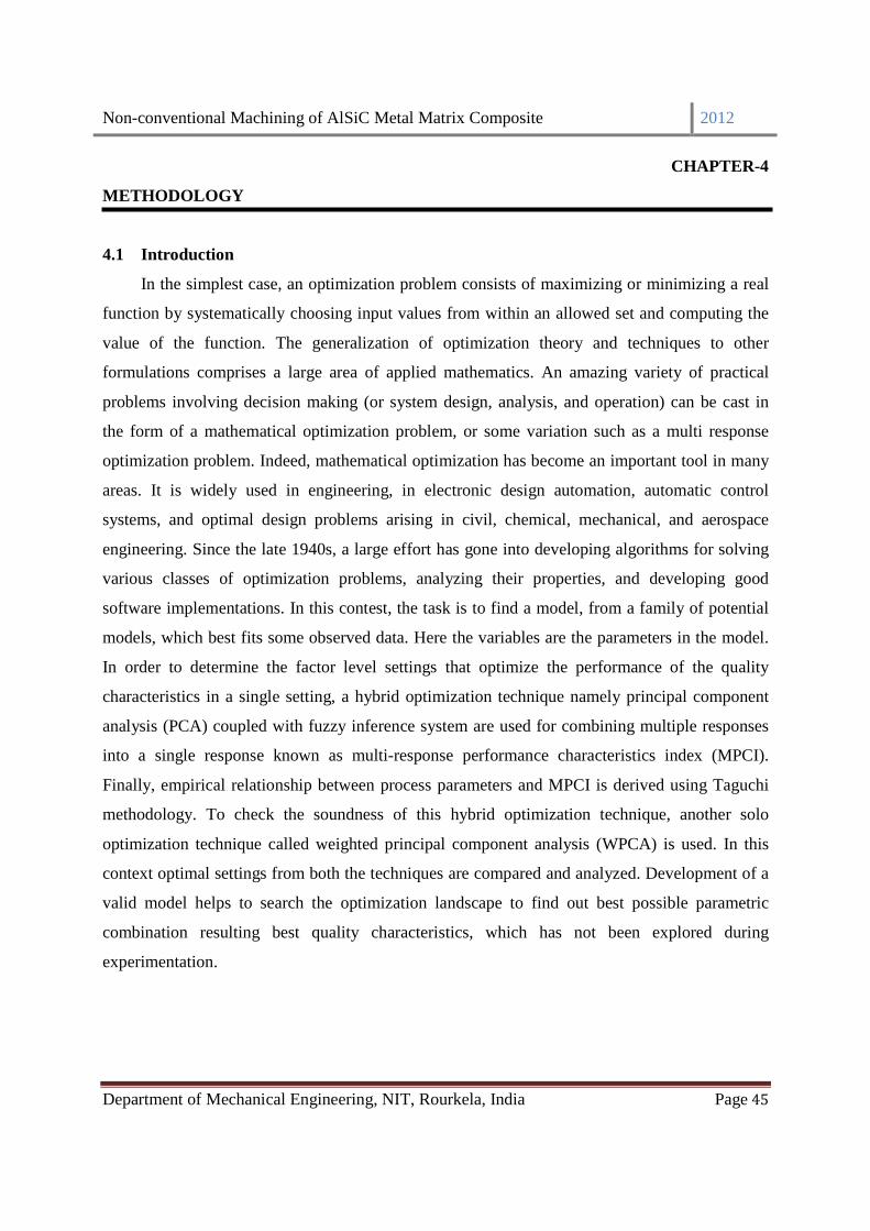
Non-conventional Machining of AlSiC Metal Matrix Composite 2012
Department of Mechanical Engineering, NIT, Rourkela, India Page 45
CHAPTER-4
METHODOLOGY
4.1 Introduction
In the simplest case, an optimization problem consists of maximizing or minimizing a real
function by systematically choosing input values from within an allowed set and computing the
value of the function. The generalization of optimization theory and techniques to other
formulations comprises a large area of applied mathematics. An amazing variety of practical
problems involving decision making (or system design, analysis, and operation) can be cast in
the form of a mathematical optimization problem, or some variation such as a multi response
optimization problem. Indeed, mathematical optimization has become an important tool in many
areas. It is widely used in engineering, in electronic design automation, automatic control
systems, and optimal design problems arising in civil, chemical, mechanical, and aerospace
engineering. Since the late 1940s, a large effort has gone into developing algorithms for solving
various classes of optimization problems, analyzing their properties, and developing good
software implementations. In this contest, the task is to find a model, from a family of potential
models, which best fits some observed data. Here the variables are the parameters in the model.
In order to determine the factor level settings that optimize the performance of the quality
characteristics in a single setting, a hybrid optimization technique namely principal component
analysis (PCA) coupled with fuzzy inference system are used for combining multiple responses
into a single response known as multi-response performance characteristics index (MPCI).
Finally, empirical relationship between process parameters and MPCI is derived using Taguchi
methodology. To check the soundness of this hybrid optimization technique, another solo
optimization technique called weighted principal component analysis (WPCA) is used. In this
context optimal settings from both the techniques are compared and analyzed. Development of a
valid model helps to search the optimization landscape to find out best possible parametric
combination resulting best quality characteristics, which has not been explored during
experimentation.

Non-conventional Machining of AlSiC Metal Matrix Composite 2012
Department of Mechanical Engineering, NIT, Rourkela, India Page 46
4.2 Taguchi method
In determining the effectiveness of a design, we must develop a measure that can evaluate
the impact of the design parameters on the output quality characteristics. This measure is
introduced by Dr. Genichi Taguchi and called “Taguchi’s philosophy”. It is an efficient tool for
the design of high quality manufacturing system. It is a widely accepted methodology for
contemporary experiment design. The Taguchi method can optimize performance characteristics
through the settings of process parameters and reduce the sensitivity of the system performance
to sources of variation. As a result, the Taguchi method has become a powerful tool in the design
of experiment methods.
Taguchi proposes a three-stage design operation to determine the nominal values for
relevant parameters in the process: system design, parameter design and tolerance design. In this
study parameter design is followed. Parameter designs involve finding the optimal settings of the
process in order to minimize performance variability. Taguchi defines a performance measure
known as signal-to-noise (S/N) ratio and tries to select the parameter levels that maximize the
ratio. The term signal represents the square of the mean value of the quality characteristic,
whereas noise is a measure of the variability (as measured by the variance) of the characteristic
[104].
However, Taguchi method is concerned with the optimization of a single performance
characteristic. Handling the more demanding multiple performance characteristics are still an
interesting research problem.
4.2.1 Performance evaluation
In order to evaluate the optimal parameter setting, Taguchi method uses a statistical
measure of performance called signal-to-noise (S/N) ratio that takes both the mean and the
variability into account. Formerly, The S/N ratio was an electrical engineering concept defined
as the ratio of signal power to noise power corrupting the signal. Taguchi expands this
conception to the engineering system design area. The philosophy of Taguchi methods stresses
that every engineering system is a man-made system, which employs energy transformation to
convert input signal(s) into specific intended function. The ratio depends on the quality
characteristics of the product/process to be optimized. The optimal setting is the parametric
combination that results in highest S/N ratio. Usually, there are three categories of signal-to-

Non-conventional Machining of AlSiC Metal Matrix Composite 2012
Department of Mechanical Engineering, NIT, Rourkela, India Page 47
noise ratios such as lower-the-better (LTB), the higher-the-better (HTB), and nominal-the-best
(NTB). In this study, four responses such as material removal rate (MRR), tool wear rate (TWR),
surface roughness (Ra) and circularity of machined component are considered. Two responses
like surface roughness and tool wear rate are to be minimized whereas two responses like
material removal rate and circularity are to be maximized. Therefore, HTB and LTB categories
of S/N ratios are dealt here.
The higher-the-better (HTB) S/N ratio is given by
y
1
n
1log10RatioN/SHTB
n
1i2i
−= ∑
= (4.1)
The lower-the-better (LTB) S/N ratio is given as
yn
1log10-RatioN/SLTB ∑
n
1i
2i
=
= (4.2)
where iy denotes the value of the response for replicate i and n is the number of replicates. The
S/N ratio measures the level of system performance and the higher value gives more robustness
of the system.
However, Taguchi method is concerned with the optimization of a single performance
characteristic. Handling the more demanding multiple performance characteristics are still an
interesting research problem. Researchers have suggested different multi-response optimization
techniques but some proposed methods increases uncertainties due to unknown correlations
among the objectives or multi performance characteristics (MPCs). To solve the correlation
problem, PCA is an advisable statistical technique to examine the correlation within the MPCs.
A new set of uncorrelated data of MPC, called principal components, could be derived by PCA
to explain the variance by generating principal component scores. Now it is fruitful to apply any
multi-objective optimization methods to the process by converting the multi-responses into a
single index i.e. multi-response performance characteristic index (MPCI). Fuzzy logic and
weighted principal component analysis will be used to calculate the MPCI value in two different
ways. Then, Taguchi method can be used to analyze MPCI to obtain best parameter setting
which simultaneously optimizes multiple responses.
Non-conventional Machining of AlSiC Metal Matrix Composite 2012
Department of Mechanical Engineering, NIT, Rourkela, India Page 48
4.3 Principal component analysis
In dealing with multiple responses, care must be taken to uncorrelate multi-response data
so that misleading interpretations during data analysis can be avoided. Independent modeling of
each response variable does not take into account the relationships or correlations among the
variables. The basic problem relates to the fitting of multi-response models while ignoring the
three kinds of dependencies that can occur: (i) dependence among the errors, (ii) linear
dependencies among the expected value of the responses and (iii) linear dependencies in the
original data. To overcome these difficulties, a strategy based on multivariate statistics for
summarizing and reducing the dimensionality of the data can be employed [105]. Such a strategy
is the principal component analysis (PCA).
Principal component analysis was invented by Karl Pearson in 1901 and developed into a
computational method by Hotelling in 1933 [106, 107]. According to hair et al. [108] principal
component analysis is a multivariate analysis method widely used for data reduction. It involves
a mathematical procedure that reduces the dimensions of a set of variables by re-constructing
them into uncorrelated combinations. PCA is a multivariate statistical method, which allows the
original initial variables to transform into another dimensional set of uncorrelated variables
called principal components (PCs). The principal components are transformed by calculating the
eigenvectors of the covariance matrix of the original inputs. The transformed variables are
ranked according to their variance reflecting a decreasing importance in order to capture the
whole information content of the original dataset. The PCs, which are expressed as linear
combinations of the original variables, are orthogonal to each other and can be used for the
effective representation of the system under investigation. To keep some observations or
variables from discriminating the calculations, the data are normalized prior to finding the
principal components. Such data preprocessing can avoid the influences of the units and the
relative spread of the data used for evaluating the multiple performance characteristics.
Normalization of the data provides fair information for determining the optimal levels of process
parameters. The original data are converted to a range 0 to 1 with 1 counting the best
performance and 0 the worst. The normalization procedure for higher-the-better characteristic is
given in equation:

Non-conventional Machining of AlSiC Metal Matrix Composite 2012
Department of Mechanical Engineering, NIT, Rourkela, India Page 49
( ) ( )[ ]( )[ ] ( )[ ] )jxmin(-)jxmax(
)jxmin(-xjx
ii
ii*i =
(4.3)
The normalization procedure for lower-the-better characteristic is shown in equation (4.4).
( ) ( )[ ] ( )( )[ ] ( )[ ])jxmin(-)jxmax(
jx-)jxmax(jx
ii
ii*i =
(4.4)
where ( )jx*i
denotes the value of the response j after normalization (In this study, the S/N ratio
values for four responses such as MRR, TWR, Ra, and circularity represent responses j=1, 2, 3,
and 4 respectively) and i denotes the experiment number.
In general PCA follows some basic steps to calculate Principal components and the steps
involved are:
Step-1: The original multi-response array
In general, for i=1,2,..,m experiments and j=1,2,..,n responses, the original multiple response
array )j(x i for S/N ratio X is given as
( ) ( ) ( )( ) ( ) ( )
( ) ( ) ( )
=
nx2x1x
nx2x1x
nx2x1x
X
mmm
222
111
L
MLMM
L
L
Step-2: Normalizing the response
For normalization of the responses, higher-the-better criterion is selected as stated in equation (3)
because higher S/N ratio of response is desirable.
( ) ( ) ( )( ) ( ) ( )
( ) ( ) ( )
=
nx2x1x
nx2x1x
nx2x1x
X
*m
*m
*m
*2
*2
*i
*1
*1
*i
*
L
MLMM
L
L
*X is the normalized response array
Step-3: Correlation coefficient array
The correlation coefficient array of the normalized response array is evaluated as follows
( )
σ×σ=
)l(x)j(x
*i
*i
jl*i
*i
)l(x),j(xCovR
(4.5)

Non-conventional Machining of AlSiC Metal Matrix Composite 2012
Department of Mechanical Engineering, NIT, Rourkela, India Page 50
where j=1,2,..n and l =1,2,..n
( ) ( )( )lx,jxcov *i
*i is the covariance of sequences ( )jx*
i and ( )lx*i ,
)j(x *i
σ and)l(x *
iσ are standard
deviation of sequences,( )jx*i and ( )lx *
i respectively.
Step-4: Determination of eigenvalues and eigenvectors
The eigenvalues and eigenvectors are calculated from the correlation coefficient array, ( ) 0VIR ikmk =λ− (4.6)
where kλ are eigenvalues, k is the number of principal components extracted, and
n1,2,k ,nn
1kk L==λ∑
=
[ ]Tknk21kik a a aV L= : Eigenvectors corresponding to the eigenvalues kλ
Step-5: Evaluating the principal components
The uncorrelated principal components (PCs) are given as
( ) ViXYn
1iik
*mmk ∑
=⋅=
(4.7)
The PCs are created in order of decreasing variance and so the first principal component, 1mY
accounts for most variance in the data. The components with an eigenvalue greater than one are
chosen to replace the original responses for further analysis [105, 109]. Still, PCA is not able to
give a final solution which could be analyzed through Taguchi method. To optimize these
principal component scores, fuzzy multiple attribute decision making process could be best
chosen to reduce uncertainties and impreciseness. Using fuzzy logic analysis, multi-responses
could be easily transformed into a single value of multi-performance characteristic indices
(MPCIs) [110]. Then, Taguchi method can be used to analyze MPCI to obtain best parameter
setting which simultaneously optimizes multiple responses.
4.4 Fuzzy inference system
Fuzzy sets and systems are introduced by Prof. Lotfi A. Zedah in 1965. According to him,
“A fuzzy set is a class of objects with a continuum of grades of membership. Such a set is
characterized by a membership (characteristics) function which assigns to each object a grade
of membership ranging between zero and one. The notations of inclusion, union, intersection,

Non-conventional Machining of AlSiC Metal Matrix Composite 2012
Department of Mechanical Engineering, NIT, Rourkela, India Page 51
complement, relation, convexity, etc., are extended to such sets, and various properties of these
notations in the context of fuzzy sets are established. In particular, a separation theorem for
convex fuzzy sets is proved without requiring that the fuzzy sets be disjoint” [111].
Fuzzy inference is a mathematical theory of inexact reasoning, which allows the human
reasoning process to be modelled in linguistic terms [112]. It is highly suitable for defining the
relationship between system inputs and desired outputs. Fuzzy inference is the process of
formulating the mapping from a given input to an output using fuzzy logic. Fuzzy controllers and
fuzzy reasoning have found particular applications in vary complex industrial systems which
cannot be modeled precisely even under a variety of assumptions and approximations. A fuzzy
system mainly composed of a fuzzifier, an inference engine, a knowledge base and a defuzzifier.
The fuzzifier first uses membership functions to convert the crisp inputs into fuzzy sets, and then
the inference engine performs a fuzzy reasoning on fuzzy rules to generate fuzzy values. Then
the defuzzifier converts these values into crisp outputs.
Block diagram of a typical fuzzy logic system is presented in Figure 4.1. As outlined in
Figure 1, a fuzzy rule based system consists of four parts: fuzzifier, knowledge base, inference
engine and defuzzifier. These four parts are described below:
• Fuzzifier: The real input (PCs) in crisp form which contains precise information about the
specific parameter is applied to the fuzzzifier. The fuzzifier converts this precise quantity to the
form of imprecise quantity like 'large', 'medium', 'high' etc. with a degree of belongingness to it.
Typically, the value ranges from 0 to 1.
• Knowledge base: The main part of the fuzzy system is the knowledge base in which both
rule base and database are jointly referred. The database defines the membership functions of the
fuzzy sets used in the fuzzy rules whereas the rule base contains a number of fuzzy IF-THEN
rules.
• Inference engine: The inference system or the decision-making unit performs the
inference operations on the rules. It handles the way in which the rules are combined.
• Defuzzifier: The output generated by the inference block is always fuzzy in nature. A real
world system will always require the output of the fuzzy system to the crisp or in the form of real
output. The job of the defuzzifier is to receive the fuzzy input and provide real world output. In
operation, it works opposite to the input block.
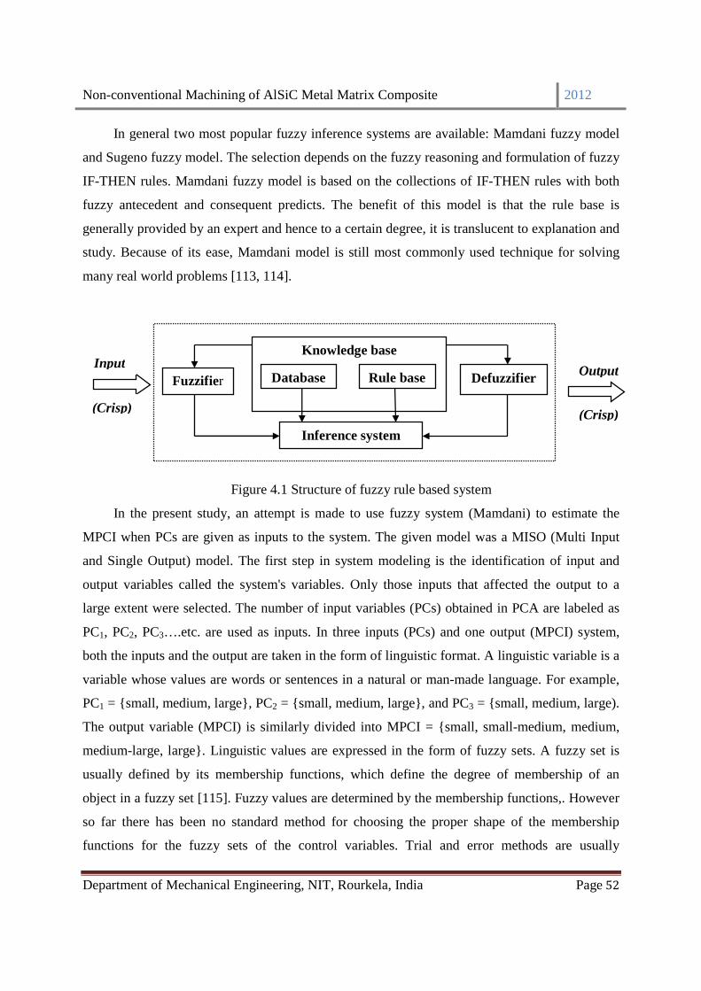
Non-conventional Machining of AlSiC Metal Matrix Composite 2012
Department of Mechanical Engineering, NIT, Rourkela, India Page 52
In general two most popular fuzzy inference systems are available: Mamdani fuzzy model
and Sugeno fuzzy model. The selection depends on the fuzzy reasoning and formulation of fuzzy
IF-THEN rules. Mamdani fuzzy model is based on the collections of IF-THEN rules with both
fuzzy antecedent and consequent predicts. The benefit of this model is that the rule base is
generally provided by an expert and hence to a certain degree, it is translucent to explanation and
study. Because of its ease, Mamdani model is still most commonly used technique for solving
many real world problems [113, 114].
Figure 1. Structure of fuzzy rule based system
Figure 4.1 Structure of fuzzy rule based system
In the present study, an attempt is made to use fuzzy system (Mamdani) to estimate the
MPCI when PCs are given as inputs to the system. The given model was a MISO (Multi Input
and Single Output) model. The first step in system modeling is the identification of input and
output variables called the system's variables. Only those inputs that affected the output to a
large extent were selected. The number of input variables (PCs) obtained in PCA are labeled as
PC1, PC2, PC3….etc. are used as inputs. In three inputs (PCs) and one output (MPCI) system,
both the inputs and the output are taken in the form of linguistic format. A linguistic variable is a
variable whose values are words or sentences in a natural or man-made language. For example,
PC1 = {small, medium, large}, PC2 = {small, medium, large}, and PC3 = {small, medium, large).
The output variable (MPCI) is similarly divided into MPCI = {small, small-medium, medium,
medium-large, large}. Linguistic values are expressed in the form of fuzzy sets. A fuzzy set is
usually defined by its membership functions, which define the degree of membership of an
object in a fuzzy set [115]. Fuzzy values are determined by the membership functions,. However
so far there has been no standard method for choosing the proper shape of the membership
functions for the fuzzy sets of the control variables. Trial and error methods are usually
Knowledge base
Database Rule base
Inference system
Fuzzifier Defuzzifier
Input
(Crisp) (Crisp)
Output
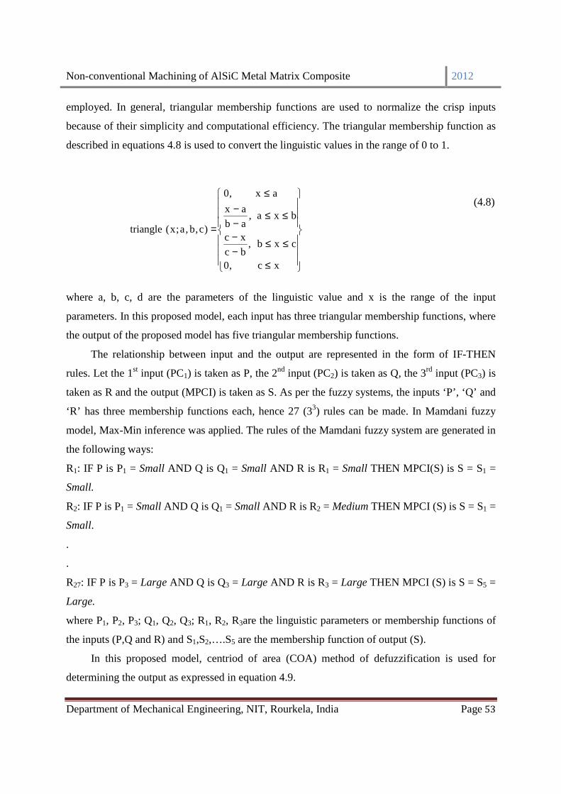
Non-conventional Machining of AlSiC Metal Matrix Composite 2012
Department of Mechanical Engineering, NIT, Rourkela, India Page 53
employed. In general, triangular membership functions are used to normalize the crisp inputs
because of their simplicity and computational efficiency. The triangular membership function as
described in equations 4.8 is used to convert the linguistic values in the range of 0 to 1.
(4.8)
where a, b, c, d are the parameters of the linguistic value and x is the range of the input
parameters. In this proposed model, each input has three triangular membership functions, where
the output of the proposed model has five triangular membership functions.
The relationship between input and the output are represented in the form of IF-THEN
rules. Let the 1st input (PC1) is taken as P, the 2nd input (PC2) is taken as Q, the 3rd input (PC3) is
taken as R and the output (MPCI) is taken as S. As per the fuzzy systems, the inputs ‘P’, ‘Q’ and
‘R’ has three membership functions each, hence 27 (33) rules can be made. In Mamdani fuzzy
model, Max-Min inference was applied. The rules of the Mamdani fuzzy system are generated in
the following ways:
R1: IF P is P1 = Small AND Q is Q1 = Small AND R is R1 = Small THEN MPCI(S) is S = S1 =
Small.
R2: IF P is P1 = Small AND Q is Q1 = Small AND R is R2 = Medium THEN MPCI (S) is S = S1 =
Small.
.
.
R27: IF P is P3 = Large AND Q is Q3 = Large AND R is R3 = Large THEN MPCI (S) is S = S5 =
Large.
where P1, P2, P3; Q1, Q2, Q3; R1, R2, R3are the linguistic parameters or membership functions of
the inputs (P,Q and R) and S1,S2,….S5 are the membership function of output (S).
In this proposed model, centriod of area (COA) method of defuzzification is used for
determining the output as expressed in equation 4.9.
≤
≤≤−−
≤≤−−
≤
=
xc,0
cxb,bc
xc
bxa,ab
ax
ax,0
)c,b,a;x(triangle

Non-conventional Machining of AlSiC Metal Matrix Composite 2012
Department of Mechanical Engineering, NIT, Rourkela, India Page 54
∫
∫
µ
µ=
z
zz
dz)z(A
dzz)z(A
COAareaofCentriod (4.9)
whereµA(z) is the membership value of set A and z is the variable.
The yielded value is the final crisp output value, which is obtained from the input variables.
This crisp value is the MPCI, Which is further analyzed through Taguchi method to get the final
optimal setting of the parameters. Finally, with the application of ANOVA (Analysis of
Variance), significant factors in this quality index and their contribution percentage for total
variation in MPCI can be obtained.
4.5 Weighted principal component analysis
To check the correctness of the PCA-Fuzzy based hybrid approach stated above, a method
called weighted principal component (WPCA) is used [116]. In order to determine the optimum
factor level setting that maximizes the performance of the quality characteristics in a single
setting, weighted principal component analysis is applied for combining multiple responses into
a single response known as MPCI.
This WPCA method follows the same steps as like PCA to calculate the principal
components/principal component scores (PCs). In addition to this, it uses the variance
(proportion explained) to calculate the MPCI without following to the complex fuzzy inference
system like in the hybrid approach. The analysis combines the variables that account for the
largest amount of variance to form the first principal component. The second principal
component accounts for the next largest amount of variance, and so on until the total sample
variance is combined into component groups. In a multiple responses case, the responses need to
be converted into an equivalent single response for analysis purpose.
For calculation of weighted principal components, the initial step is to calculate the
principal components (PCs). The PCs are calculated as per the steps prescribed in PCA. Principal
components are independent (uncorrelated) of each other. Simultaneously, the explained
variance of each principal component for the total variance of the responses is also obtained.
Next, in weighted principal component method, all principal components will be used; thus the

Non-conventional Machining of AlSiC Metal Matrix Composite 2012
Department of Mechanical Engineering, NIT, Rourkela, India Page 55
explained variance can be completely explained in all responses. Since different principal
components have their own variance to account for the total variance, the variance of each
principal component is regarded as the individual priority weight [113]. Because these principal
components are independent to each other, an additive model can be developed by simply adding
all principal components to represent multi-response performance characteristic index (MPCI).
Therefore, MPCI is given as:
(4.10)
where Ymk is the uncorrelated Principal components and Wk is the weight of kth principal
components. The weighted principal component analysis provides weights (Variance explained
by each component) for each principal component to be extracted from data rather than restoring
arbitrary and ambiguous method of assigning weights for conventional multi-responses into
equivalent single responses (MPCI). The larger the MPCI is the higher the quality. The MPCI is
further analyzed by Taguchi method and optimal parameter settings are obtained. Finally, with
the application of ANOVA (Analysis of Variance), significant factors in this quality index and
their contribution percentage for total variation in MPCI can be obtained.
4.6 Conclusion
In this present work, two multi-response optimization methods are proposed. The first one
a hybrid approach combining Principal component analysis with Fuzzy inference system (PCA-
Fuzzy) and another is Weighted Principal Component Analysis (WPCA) in combination with
Taguchi’s robust design methodology separately. The PCA-Fuzzy has been recommended to
optimize the quality indices by uncorrelating them. This method is quite practical as it uses
expert proposed rules. Based on variance; treated as individual response weights, WPCA can
combine individual principal components into a single multiresponse performance characteristics
index MPCI to be taken under consideration for optimization. This is really helpful in situations
where large number of responses have to be optimized simultaneously. Both the said approaches
can be recommended for continuous quality improvement and off-line quality control of a
process/product.
******
∑==
n
1kkmkWYMPCI
Non-conventional Machining of AlSiC Metal Matrix Composite 2012
Department of Mechanical Engineering, NIT, Rourkela, India Page 56
CHAPTER-5
RESULTS AND DISCUSSIONS
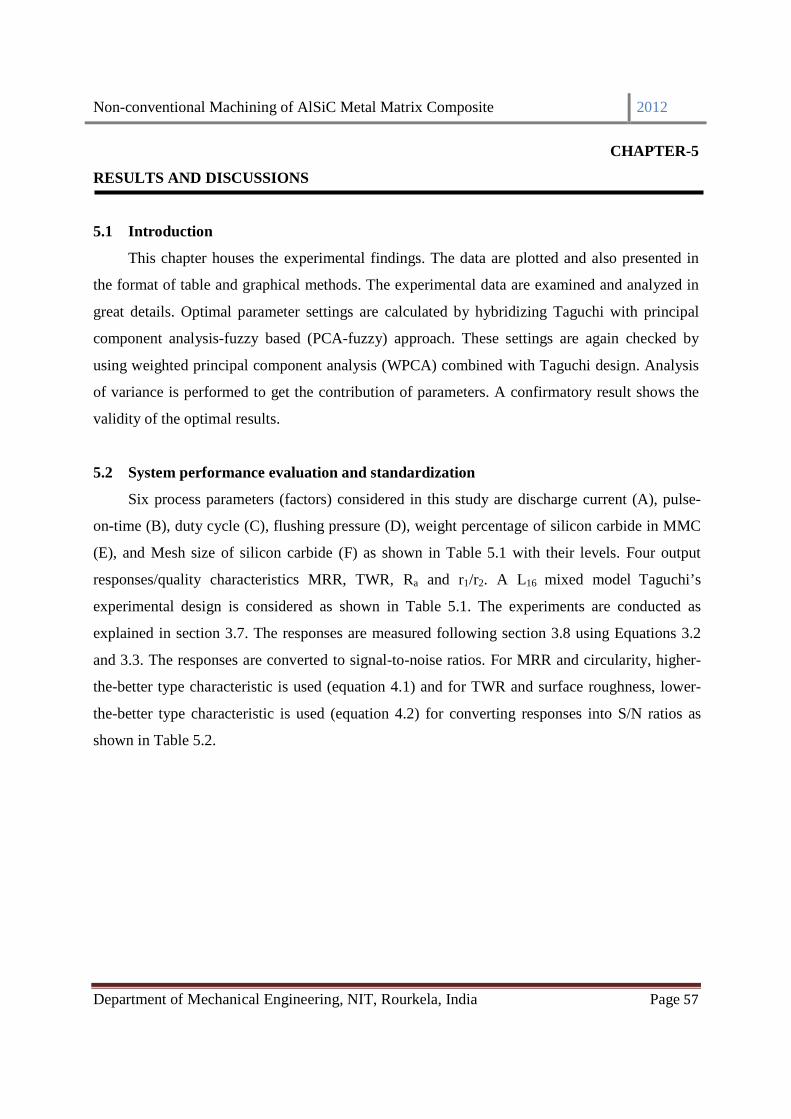
Non-conventional Machining of AlSiC Metal Matrix Composite 2012
Department of Mechanical Engineering, NIT, Rourkela, India Page 57
CHAPTER-5
RESULTS AND DISCUSSIONS
5.1 Introduction
This chapter houses the experimental findings. The data are plotted and also presented in
the format of table and graphical methods. The experimental data are examined and analyzed in
great details. Optimal parameter settings are calculated by hybridizing Taguchi with principal
component analysis-fuzzy based (PCA-fuzzy) approach. These settings are again checked by
using weighted principal component analysis (WPCA) combined with Taguchi design. Analysis
of variance is performed to get the contribution of parameters. A confirmatory result shows the
validity of the optimal results.
5.2 System performance evaluation and standardization
Six process parameters (factors) considered in this study are discharge current (A), pulse-
on-time (B), duty cycle (C), flushing pressure (D), weight percentage of silicon carbide in MMC
(E), and Mesh size of silicon carbide (F) as shown in Table 5.1 with their levels. Four output
responses/quality characteristics MRR, TWR, Ra and r1/r2. A L16 mixed model Taguchi’s
experimental design is considered as shown in Table 5.1. The experiments are conducted as
explained in section 3.7. The responses are measured following section 3.8 using Equations 3.2
and 3.3. The responses are converted to signal-to-noise ratios. For MRR and circularity, higher-
the-better type characteristic is used (equation 4.1) and for TWR and surface roughness, lower-
the-better type characteristic is used (equation 4.2) for converting responses into S/N ratios as
shown in Table 5.2.

Non-conventional Machining of AlSiC Metal Matrix Composite 2012
Department of Mechanical Engineering, NIT, Rourkela, India Page 58
Table 5.1 Experimental layout of L16 orthogonal array
Table 5.2 S/N ratio of responses
Run
No.
Control factors Responses
A B C D E F MRR
(mm3/min)
TWR
(mm3/min)
Ra
(micron)
r1/r2
1 1 1 1 1 1 1 8.7067 0.0446 4.80 0.9603
2 1 2 2 2 1 2 0.4562 0.0297 5.40 0.9367
3 1 3 3 3 2 1 0.0695 0.0037 4.40 0.9681
4 1 4 4 4 2 2 0.3160 0.0037 6.20 0.9708
5 2 1 2 3 2 2 1.5569 0.0074 7.93 0.9351
6 2 2 1 4 2 1 0.5257 0.0111 5.87 0.9303
7 2 3 4 1 1 2 4.3802 0.0148 7.53 0.9584
8 2 4 3 2 1 1 28.4699 0.0558 12.40 0.9500
9 3 1 3 4 1 2 13.5776 0.0781 7.47 0.9505
10 3 2 4 3 1 1 24.6136 0.0892 11.40 0.9577
11 3 3 1 2 2 2 5.7235 0.0223 9.20 0.9567
12 3 4 2 1 2 1 2.8857 0.0297 9.67 0.9474
13 4 1 4 2 2 1 13.4078 0.1004 8.60 0.9530
14 4 2 3 1 2 2 18.3229 0.1116 7.33 0.9523
15 4 3 2 4 1 1 35.5753 0.2232 9.07 0.9470
16 4 4 1 3 1 2 14.8260 0.0297 12.67 0.9603
Run
No.
Control factors Responses in S/N ratio (dB)
A B C D E F MRR TWR Ra r1/r2
1 1 1 1 1 1 1 18.7971 27.0049 -13.6248 -0.3517
2 1 2 2 2 1 2 -6.8163 30.5267 -14.6479 -0.5671
3 1 3 3 3 2 1 -23.1491 48.5885 -12.8691 -0.2807
4 1 4 4 4 2 2 -10.0043 48.5885 -15.8478 -0.2565

Non-conventional Machining of AlSiC Metal Matrix Composite 2012
Department of Mechanical Engineering, NIT, Rourkela, India Page 59
5.3 Principal component analysis
The responses shown in Table 5.2 have been normalized by using Eq. 4.3 to avoid the
influence of units used for evaluating the multi performance characteristics so that they lie in
between 0 to 1. Normalized performance evaluations in S/N ratio are shown in Table 5.3. The
Pearson’s correlation coefficients for the four responses are calculated using Eq. 4.5 and are
shown in Table 5.4. It indicates that reasonable amount of correlation exist among the responses.
The higher the value approaches to 1, higher will be the direct proportionality and higher the
value approaching to -1, higher will be the inverse proportionality in between responses. In all
cases non-zero value of correlation coefficient indicates that all response features are correlated
to each other. In order to eliminate response correlation Principal Component Analysis has been
applied. Using the correlation matrix, the eigenvalues and eigenvectors of the principal
components are computed. These are shown in Table 5.5. Table 5.5 shows that the PCA of the
responses from the sixteen test results for the four PCs has eigenvalues of 2.3868 1.0113 0.5365
and 0.0654. The PCs accounts 59.7%, 25.3%, 13.4 % and 1.6% of the variance contributed
respectively. The maximum possible number of the principal components to be computed is
equal to the number of responses. The proportion of variance explained by PC4 being negligible
compared to other three, so PC4 has been neglected. PC1, PC2 and PC3 have been treated as the
major principal components (PCs) [117].The matrix of the PCs can be expressed as[ ] [ ][ ]XM=Y
5 2 1 2 3 2 2 3.8456 42.5679 -17.9855 -0.5820
6 2 2 1 4 2 1 -5.5842 39.0461 -15.3728 -0.6270
7 2 3 4 1 1 2 12.8298 36.5473 -17.5359 -0.3685
8 2 4 3 2 1 1 29.0877 25.0667 -21.8684 -0.4446
9 3 1 3 4 1 2 22.6565 22.1442 -17.4664 -0.4401
10 3 2 4 3 1 1 27.8235 20.9843 -21.1381 -0.3750
11 3 3 1 2 2 2 15.1532 33.0255 -19.2758 -0.3840
12 3 4 2 1 2 1 9.2052 30.5267 -19.7085 -0.4688
13 4 1 4 2 2 1 22.5471 19.9613 -18.6900 -0.4172
14 4 2 3 1 2 2 25.2599 19.0461 -17.3021 -0.4236
15 4 3 2 4 1 1 31.0229 13.0255 -19.1521 -0.4723
16 4 4 1 3 1 2 23.4204 30.5267 -22.0555 -0.3569

Non-conventional Machining of AlSiC Metal Matrix Composite 2012
Department of Mechanical Engineering, NIT, Rourkela, India Page 60
−−−−
−=
4
3
2
1
3
2
1
X
X
X
X
150.0791.0575.0146.0
979.0134.0100.0116.0
086.0518.0576.0627.0
Y
Y
Y
(5.1)
where Y1, Y2, and Y3 are principal component scores (PCs), [M] is the eigen vectors and X1, X2,
X3, X4 are responses. The score table for PCs is computed using Eq. 4.7 and shown in Table 5.6.
The principal component scores are again normalized using equation 4.3.
Table 5.3 Normalization of S/N ratio of responses
Run
No.
Control factors Normalized responses in S/N ratio (dB)
A B C D E F MRR TWR Ra r1/r2
1 1 1 1 1 1 1 0.7743 0.3930 0.9177 0.7431
2 1 2 2 2 1 2 0.3014 0.4921 0.8063 0.1617
3 1 3 3 3 2 1 0 1 1 0.9346
4 1 4 4 4 2 2 0.2426 1 0.6757 1
5 2 1 2 3 2 2 0.4983 0.8307 0.4430 0.1213
6 2 2 1 4 2 1 0.3242 0.7316 0.7274 0
7 2 3 4 1 1 2 0.6641 0.6614 0.4919 0.6977
8 2 4 3 2 1 1 0.9642 0.3385 0.0203 0.4923
9 3 1 3 4 1 2 0.8455 0.2564 0.4995 0.5045
10 3 2 4 3 1 1 0.9409 0.2237 0.0998 0.6802
11 3 3 1 2 2 2 0.7070 0.5623 0.3025 0.6559
12 3 4 2 1 2 1 0.5972 0.4921 0.2554 0.4270
13 4 1 4 2 2 1 0.8435 0.1950 0.3663 0.5662
14 4 2 3 1 2 2 0.8936 0.1692 0.5174 0.5489
15 4 3 2 4 1 1 1 0 0.3160 0.4176
16 4 4 1 3 1 2 0.8596 0.4921 0 0.7290

Non-conventional Machining of AlSiC Metal Matrix Composite 2012
Department of Mechanical Engineering, NIT, Rourkela, India Page 61
Table 5.4 Correlation coefficient matrix for the responses
Table 5.5 Eigenvalues, eigenvectors, proportion explained and cumulative proportion explained
computed for the four responses
Table 5.6 Principal component scores
Correlation
coefficient
MRR TWR Ra Circularity
MRR 1.000
TWR -0.866 1.000
Ra -0.714 0.465 1.000
r1/r2 -0.008 0.167 0.035 1.000
PC1 PC2 PC3 PC4
Eigenvalue 2.3868 1.0113 0.5365 0.0654
Eigenvector
1. MRR -0.627 -0.116 0.146 0.757
2. TWR 0.576 -0.100 -0.575 0.572
3. Ra 0.518 0.134 0.791 0.297
4. r1/r2 0.086 -0.979 0.150 -0.107
Proportion explained or
variance (%) 59.7 25.3 13.4 1.16
Cumulative total (%) 59.7 85 98.4 100
Run
no.
PC1 Normalized
value of PC1
PC2 Normalized
value of PC2
PC3 Normalized
value of PC3
1 0.2802 0.4416 -0.7337 0.2820 0.7244 1
2 0.5260 0.5952 -0.1345 0.8791 0.4231 0.6100
3 1.1743 1 -0.8810 0.1351 0.3561 0.5233
4 0.8599 0.8037 -1.0166 0 0.1449 0.2498
5 0.4060 0.5203 -0.2003 0.8136 -0.0365 0.0153
6 0.5950 0.6383 -0.0133 1 0.2020 0.3238

Non-conventional Machining of AlSiC Metal Matrix Composite 2012
Department of Mechanical Engineering, NIT, Rourkela, India Page 62
5.4 Fuzzy inference system
The fuzzy inference system is used to integrate the PC scores to calculate the MPCIs in
order to facilitate the multi performance characteristics (MPCs) optimization of the machining
process. The Mamdani type fuzzy model is shown in Figure 5.1 and a typical input and output
membership functions are illustrated in Figures 5.2 and 5.3 respectively. All three normalized
principal component scores PC1, PC2 and PC3 are used as input. There are three fuzzy sets for the
input variables: small, medium and large and five for the outputs: small, small-medium, medium,
medium-large and large. A total of 27 rules were formed as shown in Table 5.7. Using Fuzzy
inference system of MATLAB 7.0, the three input variables are fuzzified into appropriate
linguistic values. Then, the defuzzification method is performed by the centre of gravity method
to calculate the crisp value as the MPCI outputs. A typical MPCI value for run number 1 is
shown in Figure 5.4. Three dimensional surface plots drawn on the base of fuzzy rules are shown
in figure 5.5. These plots are showing the relationship between principal components and MPCI.
These plots give useful information about the model fitted but they may not represent the true
behavior of the system. All the values of MPCI for sixteen experiments have been presented in
Table 5.8.
7 0.2794 0.4413 -0.7604 0.2553 0.2104 0.3347
8 -0.3567 0.0441 -0.6250 0.3903 0.0360 0.1089
9 -0.0803 0.2168 -0.5508 0.4643 0.4468 0.6406
10 -0.3508 0.0478 -0.7841 0.2317 0.1897 0.3078
11 0.0938 0.3253 -0.7399 0.2758 0.1176 0.2145
12 0.0780 0.3155 -0.5023 0.5126 0.0703 0.1533
13 -0.1781 0.1556 -0.6226 0.3927 0.3857 0.5615
14 -0.1475 0.1747 -0.5887 0.4265 0.5247 0.7415
15 -0.4274 0 -0.4825 0.5323 0.4586 0.6559
16 -0.1929 0.1464 -0.8626 0.1534 -0.0481 0

Non-conventional Machining of AlSiC Metal Matrix Composite 2012
Department of Mechanical Engineering, NIT, Rourkela, India Page 63
Figure 5.1 Structure of Mamdani model
Figure 5.2 Membership functions for the inputs
Figure 5.3 Membership functions for the output
0 0.5 1
S M L
µ(×)
S
0 0.5
SM M M L µ(x
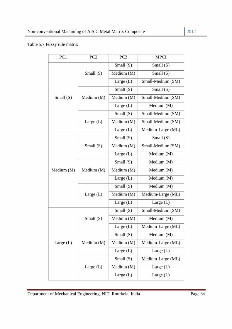
Non-conventional Machining of AlSiC Metal Matrix Composite 2012
Department of Mechanical Engineering, NIT, Rourkela, India Page 64
Table 5.7 Fuzzy rule matrix
PC1 PC2 PC3 MPCI
Small (S)
Small (S)
Small (S) Small (S)
Medium (M) Small (S)
Large (L) Small-Medium (SM)
Medium (M)
Small (S) Small (S)
Medium (M) Small-Medium (SM)
Large (L) Medium (M)
Large (L)
Small (S) Small-Medium (SM)
Medium (M) Small-Medium (SM)
Large (L) Medium-Large (ML)
Medium (M)
Small (S)
Small (S) Small (S)
Medium (M) Small-Medium (SM)
Large (L) Medium (M)
Medium (M)
Small (S) Medium (M)
Medium (M) Medium (M)
Large (L) Medium (M)
Large (L)
Small (S) Medium (M)
Medium (M) Medium-Large (ML)
Large (L) Large (L)
Large (L)
Small (S)
Small (S) Small-Medium (SM)
Medium (M) Medium (M)
Large (L) Medium-Large (ML)
Medium (M)
Small (S) Medium (M)
Medium (M) Medium-Large (ML)
Large (L) Large (L)
Large (L)
Small (S) Medium-Large (ML)
Medium (M) Large (L)
Large (L) Large (L)

Non-conventional Machining of AlSiC Metal Matrix Composite 2012
Department of Mechanical Engineering, NIT, Rourkela, India Page 65
Figure 5.4 Calculation of MPCI for experiment number 1
(a) (b)
(c)
Figure 5.5 Surface plots between Principal components (PCs) and MPCI

Non-conventional Machining of AlSiC Metal Matrix Composite 2012
Department of Mechanical Engineering, NIT, Rourkela, India Page 66
Table 5.8 MPCI values for 16 experiments
Test no. MPCI Test no. MPCI
1 0.455 9 0.360
2 0.687 10 0.252
3 0.578 11 0.358
4 0.353 12 0.394
5 0.517 13 0.329
6 0.666 14 0.368
7 0.361 15 0.363
8 0.214 16 0.300
5.5 Effects of the control factors on the MPCI
The best parameter setting that optimizes all responses simultaneously is the parametric
combination that shows highest MPCI value. The average of MPCI for each level of the control
factors are calculated and summarized in the response table (Table 5.9). The control factors are
ranked according to their ranges in MPCI value. Control factors with a large range MPCI values
among their levels have the most significant influence on the responses or multi-performance
characteristics (MPCs) of the machining process. From the responses table, it is clear that factor
A (discharge current) has the greatest effect on the performance of the machining process
followed by factor B (pulse-on-time), factor C (duty cycle), factor E (% of SiC), factor D
(flushing pressure) and factor F (mesh size) respectively. Factors A, B, C and E are regarded as
the most important parameters due to the fact that their combination directly affects the process.
Factors D and F have relatively least impact on the performance characteristics. The response
graph is plotted in Figure 5.6. From figure 5.6, it is concluded that the levels of individual control
factors which results in the largest MPCI are A1 (discharge current, 1 A), B2 (pulse-on time, 200
µS), C2 (duty factor, 85%), D4 (flushing pressure, 3.9226 bar), E2 (% of SiC, 15%), and F2 (mesh
size, 400 mesh).
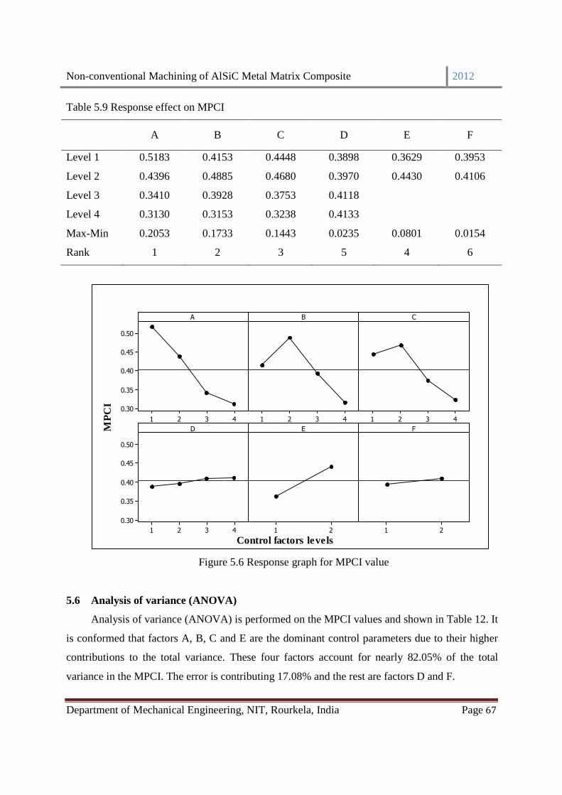
Non-conventional Machining of AlSiC Metal Matrix Composite 2012
Department of Mechanical Engineering, NIT, Rourkela, India Page 67
Table 5.9 Response effect on MPCI
A B C D E F
Level 1 0.5183 0.4153 0.4448 0.3898 0.3629 0.3953
Level 2 0.4396 0.4885 0.4680 0.3970 0.4430 0.4106
Level 3 0.3410 0.3928 0.3753 0.4118
Level 4 0.3130 0.3153 0.3238 0.4133
Max-Min 0.2053 0.1733 0.1443 0.0235 0.0801 0.0154
Rank 1 2 3 5 4 6
MP
CI
4321
0.50
0.45
0.40
0.35
0.30
4321 4321
4321
0.50
0.45
0.40
0.35
0.30
21 21
A B C
D E F
Control factors levels
Figure 5.6 Response graph for MPCI value
5.6 Analysis of variance (ANOVA)
Analysis of variance (ANOVA) is performed on the MPCI values and shown in Table 12. It
is conformed that factors A, B, C and E are the dominant control parameters due to their higher
contributions to the total variance. These four factors account for nearly 82.05% of the total
variance in the MPCI. The error is contributing 17.08% and the rest are factors D and F.

Non-conventional Machining of AlSiC Metal Matrix Composite 2012
Department of Mechanical Engineering, NIT, Rourkela, India Page 68
Table 5.10 Analysis of variance (ANOVA) on MPCI
Factor DF Seq SS Adj SS Adj MS F-value Percentage
Contribution
A 3 0.1061 0.1062 0.0354 0.6900 35.54
B 3 0.0610 0.0610 0.0203 0.4000 20.46
C 3 0.0521 0.0520 0.0173 0.3400 17.45
D 3 0.0016 0.0015 0.0005 0.0100 0.53
E 1 0.0257 0.0256 0.0256 0.5000 8.60
F 1 0.0010 0.0009 0.0009 0.0200 0.34
Error 1 0.0510 0.0509 0.0509 1.0000 17.08
Total 15 0.2985 100.00
R-Sq = 82.9 %
5.7 Weighted principal component analysis
Weighted principal component analysis (WPCA) is used to check the correctness of
optimal parameter setting, calculated by Taguchi PCA-Fuzzy hybrid approach. For WPCA the
principal component scores are calculated using the same mathematical technique used in PCA-
Fuzzy, discussed in the above section. The variances (proportion explained) of the individual
principal components shown in Table 5.5 have been treated as individual priority weights. All
three normalized principal component scores along with their corresponding variance as weights
are used to calculate the MPCI value. The MPCI is calculated using equation 4.10. The relation
for weighted principal component, MPCI is
MPCI = 0.597 × PC1 + 0.253 × PC2 + 0.134 × PC3 (5.2)
All the values of MPCI for sixteen experiments have been presented in Table 5.11.
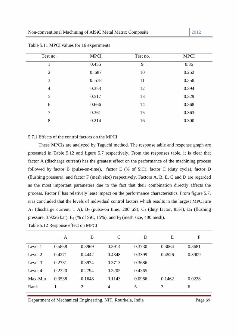
Non-conventional Machining of AlSiC Metal Matrix Composite 2012
Department of Mechanical Engineering, NIT, Rourkela, India Page 69
Table 5.11 MPCI values for 16 experiments
5.7.1 Effects of the control factors on the MPCI
These MPCIs are analyzed by Taguchi method. The response table and response graph are
presented in Table 5.12 and figure 5.7 respectively. From the responses table, it is clear that
factor A (discharge current) has the greatest effect on the performance of the machining process
followed by factor B (pulse-on-time), factor E (% of SiC), factor C (duty cycle), factor D
(flushing pressure), and factor F (mesh size) respectively. Factors A, B, E, C and D are regarded
as the most important parameters due to the fact that their combination directly affects the
process. Factor F has relatively least impact on the performance characteristics. From figure 5.7,
it is concluded that the levels of individual control factors which results in the largest MPCI are
A1 (discharge current, 1 A), B2 (pulse-on time, 200 µS), C2 (duty factor, 85%), D4 (flushing
pressure, 3.9226 bar), E2 (% of SiC, 15%), and F2 (mesh size, 400 mesh).
Table 5.12 Response effect on MPCI
A B C D E F
Level 1 0.5858 0.3969 0.3914 0.3730 0.3064 0.3681
Level 2 0.4271 0.4442 0.4348 0.3399 0.4526 0.3909
Level 3 0.2731 0.3974 0.3713 0.3686
Level 4 0.2320 0.2794 0.3205 0.4365
Max-Min 0.3538 0.1648 0.1143 0.0966 0.1462 0.0228
Rank 1 2 4 5 3 6
Test no. MPCI Test no. MPCI
1 0.455 9 0.36
2 0..687 10 0.252
3 0..578 11 0.358
4 0.353 12 0.394
5 0.517 13 0.329
6 0.666 14 0.368
7 0.361 15 0.363
8 0.214 16 0.300
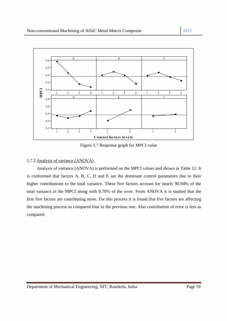
Non-conventional Machining of AlSiC Metal Matrix Composite 2012
Department of Mechanical Engineering, NIT, Rourkela, India Page 70
M
PC
I
4321
0.6
0.5
0.4
0.3
0.2
4321 4321
4321
0.6
0.5
0.4
0.3
0.2
21 21
A B C
D E F
C o ntro l factors le ve ls
Figure 5.7 Response graph for MPCI value
5.7.2 Analysis of variance (ANOVA)
Analysis of variance (ANOVA) is performed on the MPCI values and shown in Table 12. It
is conformed that factors A, B, C, D and E are the dominant control parameters due to their
higher contributions to the total variance. These five factors account for nearly 90.94% of the
total variance in the MPCI along with 8.70% of the error. From ANOVA it is studied that the
first five factors are contributing more. For this process it is found that five factors are affecting
the machining process as compared four in the previous one. Also contribution of error is less as
compared.

Non-conventional Machining of AlSiC Metal Matrix Composite 2012
Department of Mechanical Engineering, NIT, Rourkela, India Page 71
Table 5.13 Analysis of variance (ANOVA) on MPCI
Factor DF Seq SS Adj SS Adj MS F-value Percentage
Contribution
A 3 0.3116 0.31164 0.10388 2.1400 56.24
B 3 0.0593 0.05930 0.01977 0.4100 10.76
C 3 0.0272 0.02698 0.00899 0.1900 4.91
D 3 0.0199 0.01992 0.00664 0.1400 3.59
E 1 0.0855 0.08554 0.08554 1.7700 15.44
F 1 0.0021 0.00209 0.00209 0.0400 0.38
Error 1 0.0484 0.04844 0.04844 1.0000 8.70
Total 15 0.5539 100
R-Sq = 91.3 %
From the above study it is cleared that optimal parameter setting i.e. A1B2C2D4E2F2 is
same for both the cases. So the prediction of optimal parameter setting for Taguchi PCA-fuzzy
based hybrid approach is validating.
5.8 Performance prediction of the optimal design parameters
The optimal parameter setting calculated by Taguchi PCA-fuzzy base approach is same as
that of WPCA Taguchi approach. The predictive relation for optimal factor combination is given
for the MPCI value (Calculated from PCA-Fuzzy approach) in the equation 13 [118]:
)TF()TE()TD()TC()TB()TA(Tη̂ 224221MPCI −+−+−+−+−+−+= (5.2)
where MPCIη̂ is the predicted MPCI value,T is overall experimental average (MPCIs),and
224221 F and E,D,C,B,A are mean response for factors at designated levels. Predicted MPCI
value for optimal setting is found 0.727 by using the above equation 5.2 and shown in Table
5.14. As for initial conditions A1B2C3D4E2F1, the predicted MPCI is found to be 0.619. It is
observed that predicted MPCI vale for the optimal condition has 0.108 increases over the
predicted value of the initial condition.

Non-conventional Machining of AlSiC Metal Matrix Composite 2012
Department of Mechanical Engineering, NIT, Rourkela, India Page 72
Table 5.14 Comparison between initial and optimal conditions
Performance characteristics Initial condition
A1B2C3D4E2F1
Optimal condition
A1B2C2D4E2F2
Gain
MPCI confirmed 0.641 0.732 0.091
MPCI prediction 0.619 0.727 0.108
MRR (mm3/min) 6.012 8.821 2.809
TWR (mm3/min) 0.046 0.020 0.026
Surface roughness (micron) 5.769 3.071 2.698
Circularity (r1/r2) 0.967 0.977 0.010
5.9 Confirmation run
To confirm the result of the optimal condition, machining process is carried out by setting
the factors in their optimal levels and confirmed MPCI value is calculated. A comparison of the
conformation run between the optimal and initial conditions is shown in Table 5.14. From this
table, it is observed that the confirmed MPCI value is 0.732 for the optimal condition whereas it
is 0.641 for actual condition with a gain of 0.091. The gain of 0.091 in MPCI for confirmatory
test is very close to the predicted gain of 0.108. The performance of the optimal condition shows
good gain over the initial condition. The result indicates that the best combination of the control
factor levels is robust enough to achieve high productivity.
5.10 Confirmation by Thermo-Physical modeling
Researchers are developing theoretical models for accurate prediction of material removal
rate (MRR). The present study describes an intelligent technique for thermo-physical modeling
to validate the model (optimal condition) developed by the hybrid optimization methods.
5.10.1 Thermal analysis of the EDM process
During EDM process, the dielectric medium ionizes due to high potential as a result plasma
arc produced. The primary mechanism of material removal is spark erosion process which
produces large heat and melted the work piece as well as tool material. For thermal analysis
conduction is thus considered as primary mode of heat transfer. In the present study flourier heat
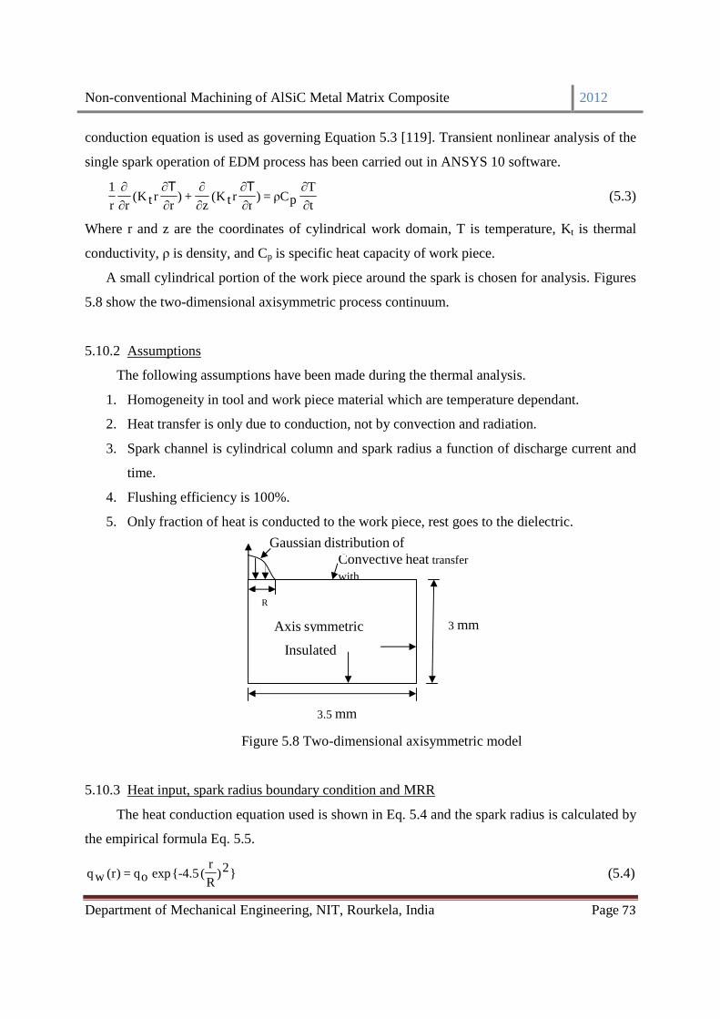
Non-conventional Machining of AlSiC Metal Matrix Composite 2012
Department of Mechanical Engineering, NIT, Rourkela, India Page 73
conduction equation is used as governing Equation 5.3 [119]. Transient nonlinear analysis of the
single spark operation of EDM process has been carried out in ANSYS 10 software.
t∂T∂
pCρ=)r∂∂T
rtK(z∂∂
+)r∂∂T
rtK(r∂∂
r
1 (5.3)
Where r and z are the coordinates of cylindrical work domain, T is temperature, Kt is thermal
conductivity, ρ is density, and Cp is specific heat capacity of work piece.
A small cylindrical portion of the work piece around the spark is chosen for analysis. Figures
5.8 show the two-dimensional axisymmetric process continuum.
5.10.2 Assumptions
The following assumptions have been made during the thermal analysis.
1. Homogeneity in tool and work piece material which are temperature dependant.
2. Heat transfer is only due to conduction, not by convection and radiation.
3. Spark channel is cylindrical column and spark radius a function of discharge current and
time.
4. Flushing efficiency is 100%.
5. Only fraction of heat is conducted to the work piece, rest goes to the dielectric.
Figure 5.8 Two-dimensional axisymmetric model
5.10.3 Heat input, spark radius boundary condition and MRR
The heat conduction equation used is shown in Eq. 5.4 and the spark radius is calculated by
the empirical formula Eq. 5.5.
}2)R
r( {-4.5 exp oq=)r(wq (5.4)
Convective heat transfer
with
Axis symmetric
Gaussian distribution of
R
3 mm
3.5 mm
Insulated boundary

Non-conventional Machining of AlSiC Metal Matrix Composite 2012
Department of Mechanical Engineering, NIT, Rourkela, India Page 74
Where qw is the heat enters to the work piece. The maximum heat flux isR
VIcF 56.4=oq , Fc is
Fraction of heat going to cathode. V discharge voltage (V), I discharge current (A), R is spark
radius in µs.
44.0dT43.0I)3-e04.2(=R (5.5)
Where I is discharge current, Td pulse-on-time.
The boundary of work piece is immersed in dielectric medium having ambient temperature (Ta)
and heat flux is applied on the top surface of the work piece at the spark region.
The material removal rate due to single spark discharge is calculated by dividing the cavity
volume into number of cylindrical discs.
Total crater volume Cv (µm3) is given by Eq. 5.6
∑−
=
=1n
0iiv DC (5.6)
Where Di is given by Eq. 5.7
)yy(2
xxD i1i
2
1iii −
+π= ++ (5.7)
where x and y are the coordinates of nodes and n is the number of nodes.
The material removal rate in mm3/min is calculated assuming all sparks are equally effective
using Eq. 5.8. The similar procedure is followed to calculate tool wear rate putting tool material
properties instead of work piece material. The MRR results are listed in Table 5.15 with results
from optimal condition for comparison.
ToffTon
C60MRR v
+×
= (5.8)
5.10.4 Solution methodology
The governing equation (Eq. 5.3) with boundary conditions is solved by Finite Element
Method to predict the temperature distribution. ANSYSTM 10.0, an FEM solver was used. The 2-
D continuum (size 0.35×0.3 mm) was considered for the analysis. An axisymmetric, four-noded,
thermal solid element (PLANE 55) was used for discretization of the continuum. Isometric
material properties, thermal conductivity were employed and following steps are followed to find
crater and temperature distribution.

Non-conventional Machining of AlSiC Metal Matrix Composite 2012
Department of Mechanical Engineering, NIT, Rourkela, India Page 75
Step 1. Model geometry is created and meshing is done using PLANE 55 thermal solid element.
Step 2. Material property such as thermal conductivity, density, heat capacity is given along with
initial and bulk temperature as 300 K.
Step 3. The heat flux location equation is imported Eq. 5.4 and applied to the spark location.
Step 4. Temperature distribution is obtained.
Step 5. The node having temperature more than melting point temperature is identified and killed
to eliminate from mesh.
Step 6. The MRR is calculated using coordinate data of the craters of work and compared with
MRR of the confirmation test (actual) for the optimal setting obtained from PCA-FIS
coupled with Taguchi hybrid approach
5.10.5 Results and comparison of models
The optimal conditions obtained from hybrid optimization techniques used as the input for
ANSYS. The inputs are 1A discharge current, 200 µs pulse-on time, 85 % duty cycle along with
AlSiC MMC material properties of density 2900 kg/mm3, Specific heat capacity of 786
Joule/kgK and melting point of 8500 C. Figure 5.9 shows the temperature contour plots, which
concludes high thermal conductivity of the material. A typical crater cavity generated by this
analysis is shown in Figure 5.10.

Non-conventional Machining of AlSiC Metal Matrix Composite 2012
Department of Mechanical Engineering, NIT, Rourkela, India Page 76
Figure 5.9 Temperature distribution using FEM analysis
Figure 5.10 Predicted crater using the FEM analysis

Non-conventional Machining of AlSiC Metal Matrix Composite 2012
Department of Mechanical Engineering, NIT, Rourkela, India Page 77
Table 5.15 Comparison between ANSYS and actual MRR
ANSYS Actual Error (%)
MRR (mm3/min) 9.970 8.821 13.03
From Table 5.15, it is observed that the MRR for the ANSYS is coming 9.970 mm3/min
obtained in thermo-physical model, which is very close to the optimal response obtained from
hybrid model with an error of 13.03% w. r. t actual MRR.. Therefore the model is validated
within and beyond the boundary of process parameter.
******
Non-conventional Machining of AlSiC Metal Matrix Composite 2012
Department of Mechanical Engineering, NIT, Rourkela, India Page 78
.
CHAPTER-6
CONCLUSIONS

Non-conventional Machining of AlSiC Metal Matrix Composite 2012
Department of Mechanical Engineering, NIT, Rourkela, India Page 79
CHAPTER-6
CONCLUSIONS
6.1 Introduction
The project work demonstrate the preparation of AlSiC metal matrix composite (MMC)
through powder metallurgy route and the effect of six process parameter on electric discharge
machining of MMC. A hybrid optimization technique (fuzzy-PCA) along with Taguchi’s design
is proposed to find the optimal setting of process parameters to give better machining
characteristic. From the present work, the following conclusions can be drawn, based on the
experimental results and the detailed discussions made.
6.2 Summary of findings
In this experimental study it is found that both density and hardness properties of the MMC is
increasing with increasing sintering temperature. The mechanical properties like density and
hardness and electrical property i.e. electrical conductivity of MMCs under investigation depend
on both, the weight percentage and mesh size of SiCp. Heat treatment after sintering is increasing
hardness as well as density. After heat treatment the percentage of density is increasing as the
SiC reinforcement, weight % and mesh size increasing. The percentage of hardness is increasing
with increasing wt. % but decreasing with increasing in mesh size of SiC after heat treatment. It
is concluded that heat treatment after sintering is influencing the properties. The density is
increasing when SiC is increasing. The hardness of MMC is increasing with increasing weight %
of SiC in the composite and mesh size. Conductivity of MMC is decreasing with increasing
weight % of SiC. From the statistical analysis, it is observed that the process parameter such as,
discharge current, pulse on time duty factor, weight % have the significant effect on the multi
performance characteristic (MPCI) contributing 82.05%. The effect of flushing pressure and
mesh size of SiC has less. Treating MPCI as an equivalent single response, the MPCI value is
analyzed by Taguchi’s method. From the response plot it is found that, the optimal setting is
1amp discharge current, 200 µs pulse-on time, 85 % duty cycle, 3.9226 bar flushing pressure,
15% of SiC, and 400 mesh sizes. With this optimal setting, the optimal responses MRR, TWR,
Surface roughness and Circularity are found as 8.821mm3/min, 0.020mm3/min, 3.071 micron and
0.977 respectively. From this experiment it is framed that a difficult-to-cut material i.e. AlSiC

Non-conventional Machining of AlSiC Metal Matrix Composite 2012
Department of Mechanical Engineering, NIT, Rourkela, India Page 80
with better mechanical properties is easily machined by the non-traditional machining process
i.e. EDM with improved quality characteristics with high dimensional accuracy. This concludes
nonconventional machining process is a good replaceable for the expensive conventional
machining process of MMCs.
Non-conventional Machining of AlSiC Metal Matrix Composite 2012
Department of Mechanical Engineering, NIT, Rourkela, India Page 81
CHAPTER-7
REFERENCES

Non-conventional Machining of AlSiC Metal Matrix Composite 2012
Department of Mechanical Engineering, NIT, Rourkela, India Page 82
CHAPTER-7
REFERENCES
[1] L.M. Manocha and A.R. Bunsell, Advances in composite materials, Pergamon Press,
Oxford, 1980, pp. 7-21.
[2] A. Berghezan, Non-ferrous Materials, Nucleus, 8(5) (1966) 5–11.
[3] A.K. Bhargava, Engineering materials: Polymers, Ceramics and Composites, PHI Pvt. Ltd.,
New Delhi, 2004, pp. 225-247.
[4] E.B. Trostyanskaya, Polymeric materials in fibre-reinforced composite material, in: R.E.
Shalin (Eds.), Polymer Matrix Composites, Chapman & Hall, Cambridge, 1995, pp. 1-4.
[5] K.Upadhya, Ceramics and composites for rocket engines and space structures, Journal of the
Minerals, Metals and Materials Society. 44(5) (1992) 15-18.
[6] K.K. Chawla, Ceramic Matrix Composites, second eds., Kluwer Academic Publishers,
Massachusetts, 2003, pp. 1-10.
[7] T.W. Clyne, An Introductory Overview of MMC System, Types and Developments, in:
T.W. Clyne (Eds.), Comprehensive Composite Materials: Vol-3, Elsevier, UK, 2000, pp.1-
26.
[8] S. Suresh, A. Mortensen, A. Needleman, Fundamentals of Metal-Matrix composites,
Bufferworth-Heinemann, Boston, 1993.
[9] R. Mehrabian, R.G. Riek, M.C. Flemings, preparation and casting of Metal-Particulate Non-
Metal Composites, Metallurgical and Materials Transitions. 5 (1974) 1899-1905.
[10] D.J. Lloyd, Particulate Reinforced Composites Produced by Molten mixing, High
Performance Composites for the 1990’s, eds. S.K.Das, C.P. Ballard and F.Marikar, TMS-
New Jersey, 1990, pp 33-46.
[11] D. Huda, M.A. El-Baradie, M.J.S. Hashmi, Metal Matrix Composites: Materials aspects.
Part II, Journal of Material Processing Technology. 37 (1993) 528-541.
[12] M.V. Roode, J. R. Price, C. Stala, Ceramic Oxide Coatings for the Corrosion Protection of
SiC, Journal of Engineering and Gas Turbines Power Transitions. 115(1) (1993) 139-149.
[13] M. Taya, R.J Arsenault, Metal Matrix Composite thermo mechanical behavior, Pergamon
press, Oxford, 1989.

Non-conventional Machining of AlSiC Metal Matrix Composite 2012
Department of Mechanical Engineering, NIT, Rourkela, India Page 83
[14] H.P. Degischer, Innovative light metals: metal matrix composites and foamed aluminium,
Materials and Design. 18 (1997) 221–226.
[15] A. Sharma, S. Das, Study of age hardening behavior of Al–4.5 wt% Cu/zircon sand
composite in different quenching media–a comparative study, Materials and Design. 30
(2009) 3900–3903.
[16] W. Pedersen, M. Ramulu, Facing SiCp/Mg metal matrix composites with carbide tools,
Journal of Materials Processing Technology. 172(3) (2006) 417-423.
[17] A.R. Ahamed, P. Asokan, S. Aravindan, EDM of hybrid Al-SiCp-B4Cp and Al-SiCp-Glassp
MMCs, International Journal of Advanced Manufacturing Technology. 44(5-6) (2009) 520-
528.
[18] X. Guo, B. Derby, Solid-state fabrication and interfaces of fibre reinforced metal matrix
composites, Progress in Materials Science. 39(4–5) (1995) 411-495.
[19] X. Xia, H.J. McQueen, Deformation Behaviour and Microstructure of a 20% Al2O3
Reinforced 6061 Al Composite, Applied Composite Materials. 4(5) (1997) 333-347.
[20] C. Sun, M. Song, Z. Wang, Y He, Effect of Particle Size on the Microstructures and
Mechanical Properties of SiC-Reinforced Pure Aluminum Composites, Journal of Materials
Engineering and Performance. 20(9) (2011) 1606-1612.
[21] N. Chawla, Y.L. Shen, Mechanical Behavior of Particle Reinforced Metal Matrix
Composites, Advanced Engineering Materials. 3(6) (2001) 357-37.
[22] T.D. Nixon, J.D. Cawley, Oxidation Inhibition Mechanisms in coated Carbon-Carbon
Composites, Journal of American Ceramic Society. 75(3) (1992) 703-708.
[23] M.V. Ravichandran, R.K Prasad, E.S. Dwarakadasa, Fracture toughness evaluation of
aluminium 4% Mg-Al2O3 liquid-metallurgy particle composite, Journal of Materials Science
Letters. 11(8) (1992) 452-456.
[24] I.N. Popescu, S. Zamfir, V.F. Anghelina, C.O. Rusanescu, Processing by P/M route and
characterization of new ecological Aluminum Matrix Composites (AMC), International
Journal of Mechanics. 3(4) (2010) 71-80.
[25] F. Bedir, B. Ogel, Investigation of hardness, microstructure and wear properties of SiC-p
reinforced Al composites. In: Proceeding of the 11th International Conference on Machine
Design and Production, Turkey, 2004.

Non-conventional Machining of AlSiC Metal Matrix Composite 2012
Department of Mechanical Engineering, NIT, Rourkela, India Page 84
[26] A.M. Davidson, D. Regener, A comparison of aluminium-based metal-matrix composites
reinforced with coated and uncoated particulate silicon carbide, Composites Science and
Technology. 60 (2000) 865-869.
[27] S. Aribo, J.A. Omotoyinbo, D.O.Folorunso, High temperature mechanical properties of
silicon carbide particulate reinforced cast aluminum alloy composite, Leonardo Electronic
Journal of Practices and Technology. 18 (2011) 321-323.
[28] S. Naher, D. Brabazon, L. Looney, Computational and experimental analysis of particulate
distribution during Al–SiC MMC fabrication, Composites Part A: Applied Science and
Manufacturing. 38(3) (2007) 719-729.
[29] M. Manoharana, M. Guptab, Effect of silicon carbide volume fraction on the work
hardening behaviour of thermomechanically processed aluminium-based metal–matrix
composites, Composites Part B: Engineering. 30(1) (1999) 107–112.
[30] V.C. Srivastava, S.N. Ojha, Microstructure and electrical conductivity of Al–SiCp
composites produced by spray forming process, Bulletin of Material Science. 28(2) (2005)
125–130.
[31] R. Karthikeyan, P.R. Lakshmi Narayanan, R.S. Naagarazan, Mathematical modelling for
electric discharge machining of aluminium-silicon carbide particulate composites, Journal of
Materials Processing Technology. 87(1-3) (1999) 59-63.
[32] T. Lemerise, C.S. Rao, G.S. Upadhyaya, 2014 and 6061 aluminium alloy-based powder
metallurgy composites containing silicon carbide particles/fibres, Materials and
Design.16(6) (1995) 21-33.
[33] V. Kevorkijan, Mg AZ80/SiC composite bars fabricated by infiltration of porous ceramic
preforms, Metallurgical and Materials Transactions A. 35(2) (2004) 707-715,
[34] M. Bahraini, E. Schlenther, J. Kriegesmann, T. Graule, J. Kuebler, Influence of atmosphere
and carbon contamination on activated pressureless infiltration of alumina–steel composites,
Composites Part A: Applied Science and Manufacturing. 41(10) (2010) 1511-1515.
[35] T.J. Sutherland, J.C. Gibeling, Fatigue crack propagation in dispersion strengthened
aluminium alloy metal matrix composite (MMC), Metal Powder Report. 47(6) (1992) 57-58.
[36] E. Sansoucy, P. Marcoux, L. Ajdelsztajn, B. Jodoin, Properties of SiC-reinforced aluminum
alloy coatings produced by the cold gas dynamic spraying process, Surface and Coatings
Technology. 202(16) (2008) 3988-3996.

Non-conventional Machining of AlSiC Metal Matrix Composite 2012
Department of Mechanical Engineering, NIT, Rourkela, India Page 85
[37] H.C Man, S Zhang, F.T Cheng, T.M Yue, In situ synthesis of TiC reinforced surface MMC
on Al6061 by laser surface alloying, Scripta Materialia. 46(3) (2002) 229-234.
[38] C. Cayron, P.A. Buffat, C. Hausmann, O. Beffort, About the epitaxial growth of Mg
subgrains on Al2MgC2 interfacial carbides in a squeeze cast Mg-4Al/T300 metal matrix
composite, Journal of Materials Science Letters.18(20) (1999) 1671-1674.
[39] S. Gopalakrishnan, N. Murugan, Production and wear characterisation of AA 6061 matrix
titanium carbide particulate reinforced composite by enhanced stir casting method,
Composites Part B: Engineering. 43(2) (2012) 302-308.
[40] S.A. Sajjadi, M.T. Parizi, H.R. Ezatpour, A. Sedghi, Fabrication of A356 composite
reinforced with micro and nano Al2O3 particles by a developed compocasting method and
study of its properties, Journal of Alloys and Compounds. 511(1) (2012) 226-231.
[41] M. Muratoğlu, O. Yilmaz, M. Aksoy, Investigation on diffusion bonding characteristics of
aluminum metal matrix composites (Al/SiCp) with pure aluminum for different heat
treatments, Journal of Materials Processing Technology. 178(1–3) (2006) 211-217.
[42] S. Scudino, G. Liu, K.G. Prashanth, B. Bartusch, K.B. Surreddi, B.S. Murty, J. Eckert,
Mechanical properties of Al-based metal matrix composites reinforced with Zr-based glassy
particles produced by powder metallurgy, Acta Materialia. 57(6) (2009) 2029-2039.
[43] C. Tatar, N. Özdemir, Investigation of thermal conductivity and microstructure of the α-
Al 2O3 particulate reinforced aluminum composites (Al/Al2O3-MMC) by powder metallurgy
method, Physica B: Condensed Matter. 405(3) (2010) 896-899.
[44] Hyun-Ki Kang, Suk Bong Kang, Thermal decomposition of silicon carbide in a plasma-
sprayed Cu/SiC composite deposit, Materials Science and Engineering. 428(1–2) (2006)
336-345.
[45] D. Tither, W. Ahmed, M. Sarwar and E. Ahmed, Application of diamond-like carbon
coatings deposited by plasma-assisted chemical vapour deposition onto metal matrix
composites for two-stroke engine components, Journal of Materials Science Letters. 14(15)
(1995) 21-27.
[46] Tien-Chai Lin, Min-Hsiung Hon, Synthesis and microstructure of the Ti3SiC2 in SiC matrix
grown by chemical vapor deposition, Ceramics International. 34(3) (2008) 631-638.

Non-conventional Machining of AlSiC Metal Matrix Composite 2012
Department of Mechanical Engineering, NIT, Rourkela, India Page 86
[47] N.P. Hung, F.Y.C. Boey, K.A. Khor, C.A. Oh, H.F. lee, Machinability of cast and powder-
formed aluminum alloys reinforced with SiC particles, Journal of Materials Processing
Technology. 48(1-4) (1995) 291-297.
[48] S. Durante, G. Rutellib, F. Rabezzana, Aluminum-based MMC machining with diamond-
coated cutting tools, Surface and Coatings Technology. 94(41) (1997) 632-640.
[49] Y. Zhu, H.A. Kishawy, Influence of alumina particles on the mechanics of machining metal
matrix composites, International Journal of Machine Tools and Manufacture. 45(4-5) (2005)
389-398.
[50] M. El-Gallab, M. Sklad, Machining Al/SiC particulate metal matrix composites, part III
comprehensive tool wear models, Journal of Materials Processing Technology. 10(1-3)
(2001) 10-20.
[51] N. Muthukrishnan, M. Murugan, K.P. Rao, Machinability issues in turning Al-SiC (10%)
metal matrix composites, International Journal of Advanced Manufacturing Technology.
17(3-4) (2008) 1220-1228.
[52] E. Kılıckap, O.C. akır, M. Aksoy, A. Inan, Study of tool wear and surface roughness in
machining of homogenized SiCp reinforced aluminium metal matrix composite, Journal of
Materials Processing Technology. 164(2) (2005) 862-867.
[53] X. Li, W.K.H. Seah, Tool wear acceleration in relation to workpiece reinforcement
percentage in cutting of metal matrix composites, Wear 247 (2001) 161–171.
[54] A. Pramanik, L.C. Zhang, J.A. Arsecularatne, An FEM investigation into the behavior of
metal matrix composites: tool–particle interaction during orthogonal cutting, International
Journal Machine Tools and Manufacture. 47(10) (2007) 1497-1506.
[55] A. Manna, B Bhattacharyya, A study on different tooling system during machining of
Al/SiC-MMC, Journal of Materials Processing Technology. 123(3) (2002) 476-482.
[56] I. Ciftci, M. Turker, U.Seker, Evaluation of tool wear when machining SiCp-reinforced Al-
2014 alloy matrix composites, Materials and Design. 25(3) (2004) 251-255.
[57] L.A. Looney, J.M. Monagham, P. O’Reilly, D.M.R. Taplin, The turning of an Al/SiC metal-
matrix composites. Journal of Materials Processing Technology. 33(4) (1992) 453-468.
[58] J.P. Davim, Design of optimization of cutting parameters for turning metal matrix
composites based on the orthogonal arrays, Journal Materials Processing Technology,
132(1-3) (2003) 340-344.

Non-conventional Machining of AlSiC Metal Matrix Composite 2012
Department of Mechanical Engineering, NIT, Rourkela, India Page 87
[59] X. Ding, W.Y.H. Liew, X.D. Liu, Evaluation of machining performance of MMC with
PCBN and PCD tools, Wear. 259(7-12) (2005) 1225-1234.
[60] A. Kremer, M.E. Mansori, Tool wear as-modified by particle generation in dry machining,
Wear. 271(9-10) (2011) 2448-2453.
[61] F. Muller, J. Monaghan, Non-conventional machining of particle reinforced metal matrix
composite, International Journal of Machine Tools and Manufacture. 40(9) (2000) 1351-
1366.
[62] B. Mohan, A. Rajadurai, K.G. Satyanarayana, Effect of SiC and rotation of electrode on
electric discharge machining of Al-SiC composite, Journal of Materials Processing
Technology. 124(3) (2002) 297-304.
[63] K.L. Senthil kumar, R. Sivasubramanian, K. Kalaiselvan, Selection of optimum parameters
in non-conventional machining of metal matrix composite, Portugaliae Electrochimica Acta.
27(22) (2009) 477-486.
[64] S. Murugesan, K. Balamurugan, C. Sathyanarayanan, P.G. Venkatakrishnan, Study on EDM
of Al-15%SiC MMC using Solid and Multihole Electrodes-A Taguchi Approach, European
Journal of Science and Research 68(1-2) (2012) 161-171.
[65] N.R. Prabhuswamy, C.S. Ramesh, T. Chandrashekar, Effect of heat treatment on strength
and abrasive wear behaviour of Al6061-SiCp composites,. 33(1) (2010) 49-54.
[66] A.K. Khanra, S. Patra, M.M. Godkhindi, Electrical discharge machining studies on reactive
sintered FeAl, Bulletin of Materials Science. 29(3) (2006) 227–280.
[67] K.H. Ho, S.T. Newman, State of the art electrical discharge machining (EDM) International
Journal of Machine Tools and Manufacture. 43(13) (2003) 1287-1300.
[68] B. Lauwers, J.P. Kruth, K. Brans, Development of Technology and Strategies for the
Machining of Ceramic Components by Sinking and Milling EDM, CIRP Annuals
Manufacturing Technology. 56(1) (2007) 225-228.
[69] A.R. Ahamed, P. Asokan, S. Aravindan, EDM of hybrid Al-SiCp-B4Cp and Al-SiCp-Glassp
MMCs, International Journal of Advanced Manufacturing Technology. 44(5-6) (2009) 520-
528.
[70] W.M. Khairaldien, A.A. Khalil, M.R. Bayoumi, Production of aluminum-silicon carbide
composites using powder metallurgy at sintering temperatures above the aluminum melting
point, Journal of Testing and Evaluation. 35(6) (2007) 111-125.

Non-conventional Machining of AlSiC Metal Matrix Composite 2012
Department of Mechanical Engineering, NIT, Rourkela, India Page 88
[71] A. Slipenyuk V. Kuprin Yu. Milman V. Goncharuk J. Eckert Properties of P/M processed
particle reinforced metal matrix composites specified by reinforcement concentration and
matrix-to-reinforcement particle size ratio, Acta Materialia. 54(1) (2006) 157–166.
[72] H. Abdizadeh, M. Ashuri, P. T. Moghadam, A. Nouribahadory, H. R. Baharvandi,
Improvement in physical and mechanical properties of aluminum/zircon composites
fabricated by powder metallurgy method, Materials and Design. 32 (2011) 4417–4423.
[73] K. Itatani, K. Hattori, D. Harima, M. Aizawa, I. Okada, I. J. Davies, H. Suemasu, A. Nozue,
Mechanical and thermal properties of silicon-carbide composites fabricated with short
Tyranno Si-Zr-C-O fiber, Journal of Materials Science. 36(15) (2001) 3679-3686.
[74] S. Scudino, K. B. Surreddi S. Sager, M. Sakaliyska, J.S. Kim, W. Loser and J. Eckert,
Production and mechanical properties of metallic glass-reinforced Al-based metal matrix
composites, Journal of Materials Science. 43(2008) 4518-4526.
[75] A. Singh, A. Ghosh, A thermo-electric model of material removal during electric discharge
machining, International Journal of Machine Tools and Manufacture. 39(7) (1999) 669–682.
[76] A. Gadalla,W. Tsai, Machining of WC-Co composites, Materials and Manufacturing
Processes. 4(3) (1989) 411–423.
[77] T.C. Lee, W.S. Lau, Some characteristics of electrical discharge machining of conductive
ceramics, Materials and Manufacturing Processes. 6 (4) (1991) 635–648.
[78] B. Lauwers, J.P. Kruth, K. Brans, Development of Technology and Strategies for the
Machining of Ceramic Components by Sinking and Milling EDM. CIRP Annuals
Manufacturing Technology. 56(1) (2007) 225-228.
[79] J.A. Sanchez, I. Cabanes, L.N.L Lacalle, A. Lamikiz, Development of optimum
electrodischarge machining technology for advanced ceramics, International Journal of
Advanced Manufacturing Technology. 18(12) (2001) 897–905.
[80] T. Tani, Y. Fukuzawa, N. Mohri, N. Saito, M. Okada, Machining phenomena in WEDM of
insulating ceramics, Journal of Materials Processing Technology. 149(1–3) (2004) 124–128.
[81] Y.H. Liu, R.J. Ji, X.P. Li, L.L. Yu, H.F. Zhang, Q.Y. Li, Effect of machining fluid on the
process performance of electric discharge milling of insulating Al2O3 ceramic, International
Journal of Machine Tools and Manufacturing. 48(9) (2008) 1030–1035.

Non-conventional Machining of AlSiC Metal Matrix Composite 2012
Department of Mechanical Engineering, NIT, Rourkela, India Page 89
[82] K. Bonny, P. De-Baets, J. Vleugels, A. Salehi, O.V. Biest, B. Lauwers, W. Liu, EDM
machinability and frictional behavior of ZrO2-WC composites, International Journal of
Advanced Manufacturing Technology. 41(11-12) (2009) 1085-1093.
[83] A. Khan, M. Ali, M. Haque, A study of electrode shape configuration on the performance of
die sinking EDM, International Journal of Mechanical and Materials Engineering. 4(1)
(2009) 19–23.
[84] A. Khan, Electrode wear and material removal rate during EDM of aluminum and mild steel
using copper and brass electrodes, International Journal of Advanced Manufacturing
Technology, 39(5-6) (2008) 482–487.
[85] S. Dhar, R. Purohit, N. Saini, A. Sharma, G.H. Kumar, Mathematical modeling of electric -
discharge machining of cast Al-4Cu-6Si alloy-10 wt.% SiCP composites, Journal of
Materials Processing Technology. 194 (2007) 24–29.
[86] T. El-Taweel, Multi-response optimization of EDM with Al-Cu-Si-TiC P/M composite
electrode, International Journal of Advanced Manufacturing Technology. 44(3) (2008) 100-
113.
[87] A. Dvivedi, P. Kumar, I. Singh, Experimental investigation and optimization in EDM of al
6063 SiCp metal matrix composite, International Journal of Machining and Machinability of
Materials. 3(3-4) (2008) 293–308.
[88] C.C. Wang, Y. Lin, Feasibility study of electrical discharge machining for W/Cu composite,
International Journal of Refractory Metals and Hard Materials. 27(5) (2009) 872–882.
[89] K. Chiang, Modeling and analysis of the effects of machining parameters on the
performance characteristics in the EDM process of Al2O 3+TiC mixed ceramic,
International Journal of Advanced Manufacturing Technology. 37(5-6) (2008) 523–533.
[90] M. Ghoreishi, J. Atkinson, A comparative experimental study of machining characteristics
in vibratory, rotary and vibro-rotary electro-discharge, Journal of Materials Processing
Technology. 120(1-3) (2002) 374-378.
[91] M. Kathiresan, T. Sornakumar, EDM Studies on aluminum alloy-silicon carbide composites
developed by vortex technique and pressure die casting, Journal of Mineral and Materials
Characterization and Engineering. 9(1) (2010) 79-88.
Non-conventional Machining of AlSiC Metal Matrix Composite 2012
Department of Mechanical Engineering, NIT, Rourkela, India Page 90
[92] C. Ahilan, S. Kumanan, N. Sivakumaran, Application of gray based Taguchi method in
multi response optimization of turning process, Journal of Advance Production Engineering
and Management. 5(3) (2010) 171-180.
[93] C.P. Fung, K. Po-Chung, Multi-response optimization in friction properties of PBT
composites using Taguchi method and principle component analysis, Journal of Materials
Processing Technology. 170(3) (2005) 602-610
[94] A. Gupta, H. Singh, A. Aggarwal, Taguchi-fuzzy multi output optimization (MOO) in high
speed CNC turning of AISI P-20 tool steel, Expert System and Applications. 38(6) (2011)
6822-6828.
[95] G. Ganesan, K. Raghukandan, R. Karthikeyan, B.C. Pai, Development of processing map
for 6061 Al/15% SiCp through neural networks, Journal of Materials Processing
Technology. 166(3-4) (2005) 423–429.
[96] S. Ramanathan, R. Karthikeyan, M. Gupta, Development of processing maps for Al/SiCp
composite using fuzzy logic, Journal of Materials Processing Technology. 183(7) (2007)
104–110
[97] H.S. Chen, J.C. Lin, Y.K. Yang, C.H. Tsai, Optimization of wire electrical discharge
machining for pure tungsten using a neural network integrated simulated annealing
approach. Expert System and Application. 37(10) (2010) 7147-7153.
[98] A.N. Haq, P. Marimuthu, R. Jayapaul. Multi response optimization of machining parameters
of drilling Al/SiC metal matrix composite using grey relational analysis in the Taguchi
method, International Journal of Advanced Manufacturing Technology. 37(3-4) (2008) 250-
255.
[99] A. Aggarwal, H. Singh, P. Kumar, M. Singh, Multi-characteristic optimization of CNC
turned parts using principal component analysis, International Journal Machining and
Machinability of Materials. 3(1-2) (2008) 208-223.
[100] T. Sritharan, L.S. Chan, L.K. Tan ,N.P. Hung, A feature of the reaction between Al and
SiC particles in an MMC, Materials Characterization. 47(1) (2001) 75–77.
[101] J. Fleischer, J. Schmidt, S. Haupt, Combination of electric discharge machining and laser
ablation in microstructuring of hardened steels, Microsystems Technology. 12(7) (2006)
697-701.
Non-conventional Machining of AlSiC Metal Matrix Composite 2012
Department of Mechanical Engineering, NIT, Rourkela, India Page 91
[102] C.F.J. Wu, M. Hamada, Experiments: Planning, Analysis, and Parameter Design
Optimization, John Wiley & Sons, New Delhi, India, 2002.
[103] D.C. Montgomery, Design and Analysis of Experiments, John Wiley & Sons, Singapore,
2003.
[104] A. Mitra, Fundamentals of quality control and improvement, Macmillan publishing
company, New York, 1993.
[105] A.P. Paiva, J.R. Ferreira, P.P. Balestrassi, A multivariate hybrid approach applied to AISI
52100 hardened steel turning optimization, Journal of Materials Processing Technology.
189(1-3) (2007) 26-35.
[106] K. Pearson, On Lines and Planes of Closest Fit to Systems of Points in Space,
Philosophical Magazine. 2 (6) (1901) 559–572.
[107] R.A. Johnson, D.W. Wichern, Applied multivariate statistical analysis, 5th ed., Upper
Saddle River, New Jersey, Prentice Hall, 2002.
[108] J.F. Hair, W.C. Black, B.J. Babin, R.E. Anderson, R.L. Tatham, Multivariate data
analysis, Prentice Hall, New Jersey, 2006.
[109] C.P Fung, K. Po-Chung, Multi-response optimization in friction properties of PBT
composites using Taguchi method and principle component analysis, Journal of Materials
Processing Technology. 170(3) (2005) 602-610.
[110] F.Y. Chin, T.Y. Fong, L.S. Xiang, A Taguchi PCA fuzzy-based approach for the multi-
objective extended optimization of a miniature optical engine, Journal of Physics and
Applied Physics. 41(17) (2008) 175108-175123.
[111] L. A. Zedah, Fuzzy sets. Information and Control, 8 (1965) 338–353.
[112] E.A. Elsayed, A. Chen, Optimal levels process parameters for products with multiple
characteristics, International Journal of Production Research. 31(5) (1993) 53-70.
[113] E. H. Mamdani, S. Assilian, An experiment in linguistic synthesis with a fuzzu logic
controller, International Journal of Man-Machine Studies. 7(1) (1975) 1–13.
[114] M. Assadi, H. Cheraghi, A fuzzy rule-based in-process inspection and control system for
a gear-hobbing process, International Journal of Industrial and system Engineering. 4(3)
(2009) 283-302.

Non-conventional Machining of AlSiC Metal Matrix Composite 2012
Department of Mechanical Engineering, NIT, Rourkela, India Page 92
[115] J. Antony, Simultaneous optimization of multiple quality characteristics in manufacturing
process using Taguchi’s quality loss function, International Journal of Advanced
Manufacturing Technology. 17(2) (2001) 134-138.
[116] H.C. Liao, Multi-Response Optimization using Weighted Principal Component,
International Journal of Advanced Manufacturing Technology, vol. 27, 2006, pp. 720-725.
[117] S. Moshat, S. Datta, A. Bandyopadhyay, P.K. Pal. Optimization of CNC end-milling
process parameters using PCA-based Taguchi method, International Journal of Engineering
Science and Technology. 2(1) (2010) 92-102.
[118] G.S. Peace, Taguchi Methods: A Hands-On Approach, Addision-Wesley, Massachusetts,
1993.
[119] S.N. Joshi, S.S Pande, Development of an intelligent process model for EDM,
International Journal of Advanced Manufacturing Technology. 45(3) (2009) 300-317.
*******

Non-conventional Machining of AlSiC Metal Matrix Composite 2012
Department of Mechanical Engineering, NIT, Rourkela, India Page 93
LIST OF PUBLICATIONS Journals
1. Debaprasanna Puhan, S.S. Mahapatra, Jambeswar Sahu, L.D. Das; “A hybrid approach for multi-response optimization of non-conventional machining on AlSiCp MMC”, Measurement. (Communicated)
2. J. Sahu, Debaprasanna Puhan, S.S. Mahapatra; “Parametric Optimization of Electric Discharge Machining Process using Response Surface Methodology and Particle Swarm Optimization”, International Journal of Experimental Design and Process Optimization (IJEDPO). (Communicated)
3. J. Sahu, S.S. Mahapatra , Debaprasanna Puhan, L.D. Das; “Parametric optimization of electric discharge machining by comparing of fuzzy logic and data envelopment analysis using anfis”, National Conference on Emerging Trend & its Application in Engineering (NCETAE 2011), International Journal of Computer Sciences, Software Engineering and Electrical Communication Engineering (IJCSSEECE) ISSN: 2229-3175. Second level of review (R2).
International conferences
1. Debaprasanna Puhan, L.D. Das, J. Sahu, S.S. Mahapatra; “Multi-objective Optimization of Electric Discharge Machining Process Parameters”, International Conference on Modeling, Optimisation and Computing, NIU, Tamilnadu, India, 2012.
2. J. Sahu, L.D. Das, Debaprasanna Puhan, S.S. Mahapatra; “Optimization of multiple responses in electric discharge machining using data envelopment analysis”, International Conference on Advances in Modeling, Optimization and Computing, (AMOC 2011) IIT Roorkee, India-247667, during Dec 5-7 2011.
3. L.D. Das, Debaprasanna Puhan, J. Sahu, S.S. Mahapatra; “Multiple responses optimization of electric discharge machining using TOPSIS method”, International Conference on Advances in Modeling, Optimization and Computing, (AMOC 2011) IIT Roorkee, India-247667, during Dec 5-7 2011.
4. J. Sahu, S S Mahapatra, R K Sahu, Debaprasanna Puhan, H Pradhan; “Electric Discharge Machining Process Parameter Optimization using Particle Swarm Optimization”, International Conference on Modelling, Optimisation and Computing, NIU, Tamilnadu, India, 2012.
National conferences
1. Debaprasanna Puhan, J. Sahu, S.S. Mahapatra, L.D. Das; “Parametric optimization of electric discharge machining by comparing of fuzzy logic and data envelopment analysis using anfis”, National Conference on Emerging Trend & its Application in Engineering (NCETAE 2011), Indira Gandhi Institute of Technology (IGIT), Sarang, Odisha, India-759146, p:165-169, 2011.
2. J. Sahu, S.S. Mahapatra, Debaprasanna Puhan, L.D. Das; “Optimization of the electric discharge machining process of AISI D2 steel by Fuzzy Logic and Response Surface Method”, National Conference on Emerging Trend & its Application in Engineering(NCETAE 2011), Indira Gandhi Institute of Technology (IGIT), Sarang, Odisha, India-759146, p:170-174, 2011.
3. J. Sahu, H. Pradhan, Debaprasanna Puhan, S.S. Mahapatra, S. Datta; “Parametric optimization of electrical discharge machining by neuro-fuzzy and particle swarm optimization designed by response surface method”, National conference On advances in simulation & optimization Techniques in mechanical engineering (NASOME 2012), Kalinga Institute of Indusrtial Technology, KIIT University, Bhubaneswar, Odisha, India-751024, during Feb 18-19 2012.
Related Documents