Nominal RF Design Link Budget Maximum path loss Propagation model Typical site configuration Site radius Nominal RF Design (coverage) Coverage requirements Nominal site count Coverage site count • Transmit Power • Antenna configuration (type, height, azimuth) • Site type (sector, omni) Traffic requirements • Standard hexagon site layout • Friendly, candidate sites • Initial site survey inputs Traffic site count Traffic > Cov. Cov. > Traffic • Recalculate the site radius using the number of sites from the traffic requirement • Repeat the nominal RF design Traffic requirements

Welcome message from author
This document is posted to help you gain knowledge. Please leave a comment to let me know what you think about it! Share it to your friends and learn new things together.
Transcript

Nominal RF Design
Link Budget
Maximum
path loss
Propagation
model
Typical site
configuration
Site radius
Nominal RF
Design
(coverage)
Coverage
requirements
Nominal site count
Coverage site
count
• Transmit Power
• Antenna configuration
(type, height, azimuth)
• Site type (sector, omni)
Traffic
requirements
• Standard hexagon site
layout
• Friendly, candidate sites
• Initial site survey inputs
Traffic site
count
Traffic > Cov.
Cov. > Traffic
• Recalculate the site
radius using the
number of sites from
the traffic requirement
• Repeat the nominal
RF design
Traffic requirements

Nominal RF Design
• Calculation of cell radius
• A typical cell radius is calculated for each clutter environment
• This cell radius is used as a guide for the site distance in the respective clutter environment
• The actual site distance could varies due to local terrain
• Inputs for the cell radius calculation :-
• Maximum pathloss (from the link budget)
• Typical site configuration (for each clutter environment)
• Propagation model

Nominal RF Design
• There are different level of nominal RF design :-
• Only using the cell radius/site distance calculated and placing ideal hexagon cell layout
• Using the combination of the calculated cell radius and the existing/friendly sites from the customer
The site distance also depends on the required capacity
•In most mobile network, the traffic density is highest within the CBD area and major routes/intersections
•The cell radius would need to be reduce in this area to meet the traffic requirements
•BASED ON THE SITE DISTANCE & THE COVERAGE REQUIREMENTS CELL COUNT BASED ON COVERAGE IS CALCULATED.
Nominal RF Design
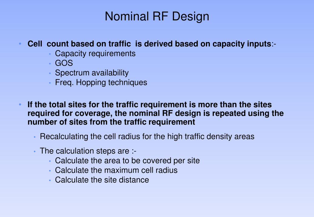
• Cell count based on traffic is derived based on capacity inputs:- • Capacity requirements • GOS • Spectrum availability • Freq. Hopping techniques
• If the total sites for the traffic requirement is more than the sites required for coverage, the nominal RF design is repeated using the number of sites from the traffic requirement
• Recalculating the cell radius for the high traffic density areas
• The calculation steps are :- • Calculate the area to be covered per site • Calculate the maximum cell radius • Calculate the site distance

Site Realisation
• After completion of Nominal design based on cell count ( coverage & capacity requirements) , search rings for each cell site issued.
• Nominal design is done , with the existing network in place(existing BTS). Existing site location remain unchanged , azimuth , tilts as per the new design requirements.
• Based on the search ring form physical site survey is undertaken.

Site Realisation
Search Ring Form
• Site ID
• Site Name
• Latitude/Longitude
• Project name
• Issue Number and date
• Ground height
• Clutter environment
• Preliminary configuration
• Number of sector
• Azimuth
• Antenna type
• Antenna height
• Location Map & SR radius
• Search ring objective
• Approvals
Spheroid:
Coordinates: (GPS)
o ' ''N
o ' ''E
Site AGL (m): 30 Antenna Type: 65 deg Vertical polarised
Antenna Orientation(Deg)
Coverage Objectives:
Revision No. : R1.1
Name & signature of RF Coordinator
Comments
Krishna Nagar, Jotiba Nagar, Shambaji Nagar, Yamuna Nagar
BSNL Circle:Haryana
Krishna Nagar
City / SSA:
Search Radius:50 m
350 120
Sector1 Sector2 Sector3
sec
18 39
240
Search Ring Form
Site Name: Site Id:
Morphology Type: Quasi Open , Industrial
47 36.7
WGS-84
Issue Date:
Longitude: 73
Latitude: 49.3
deg min
Site Realisation
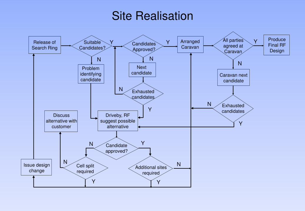
Release of Search Ring
Suitable Candidates?
Candidates
Approved?
Arranged Caravan
All parties agreed at
Caravan
Produce Final RF
Design
Caravan next candidate
Exhausted candidates
Additional sites required
Cell split required
Candidate
approved?
Driveby, RF
suggest possible alternative
Next
candidate Problem
identifying
candidate
Discuss
alternative with customer
Issue design change
Exhausted candidates
Y
N
Y Y
Y
Y
Y Y
N N
N
N
N N
Y N

Site Realisation
• Candidate Assessment Report-Site Survey Forms
• Site survey Forms for all suitable candidates for the search ring
• For each candidates :- • Location (latitude/longitude) • Location map showing the relative location of the candidates and
also the search ring • Candidate information (height, owner etc) • Photographs (360º set, rooftop, access, building) • Possible antenna orientations • Possible base station equipment location • Information for any existing antennas • Planning reports/comments (restrictions, possibilities of approval
etc.)

Site Realisation-Site Survey Form
• Final RF Configuration Form
• Base Station configuration • Azimuth • Antenna height • Antenna type • Down tilt • Antenna location • Feeder type and length • BTS type • Transmit power • Transceiver
configuration
Date
BSNL Circle
CITY / SSA
Site ID
Site Name
Owner Name
Address & Contact No.
Construction
Tower Type Bldg. Hgt
Tower Hgt Antenna Ht
Coordinate LAT N LONG E
GSM ANTENNA :
AZ M-TILT
SECTOR 1 85° +1.9 Spheroid:
SECTOR 2 185° +0.7
SECTOR 3 307° +1.3
Candidate No.
Assess: Priority
Morphology/Clutter
Site Blockage if Any
Remark
Name: Name:
Signature: Signature:
BSNL/ NBSNL
20 m.
GBT / Rooftop 10 m.
6 m.
AP909014-2
BSNL Survey Team Representative Nokia Representative
Accept/ Reject
TECHNICAL SITE SURVEY FORM
June 12, 2004
BHPAT-09
Bihar
AP909014-2
AP909014-2
Patna 09
Container/Room
85° 48 ' 31.2"26° 21' 25.9"
TYPE
Traffic Engineering
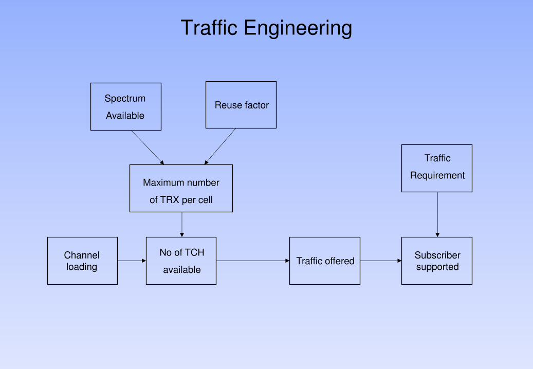
Spectrum
Available Reuse factor
Maximum number
of TRX per cell
No of TCH
available Traffic offered
Traffic
Requirement
Subscriber supported
Channel loading

Traffic Engineering
• Traffic Requirement
• The Erlang per subscriber
• Grade of Service (GoS)
• GoS is expressed as the percentage of call attempts that are blocked during peak traffic
• Most cellular systems are designed to a blocking rate of 1% to 5% during busy hour
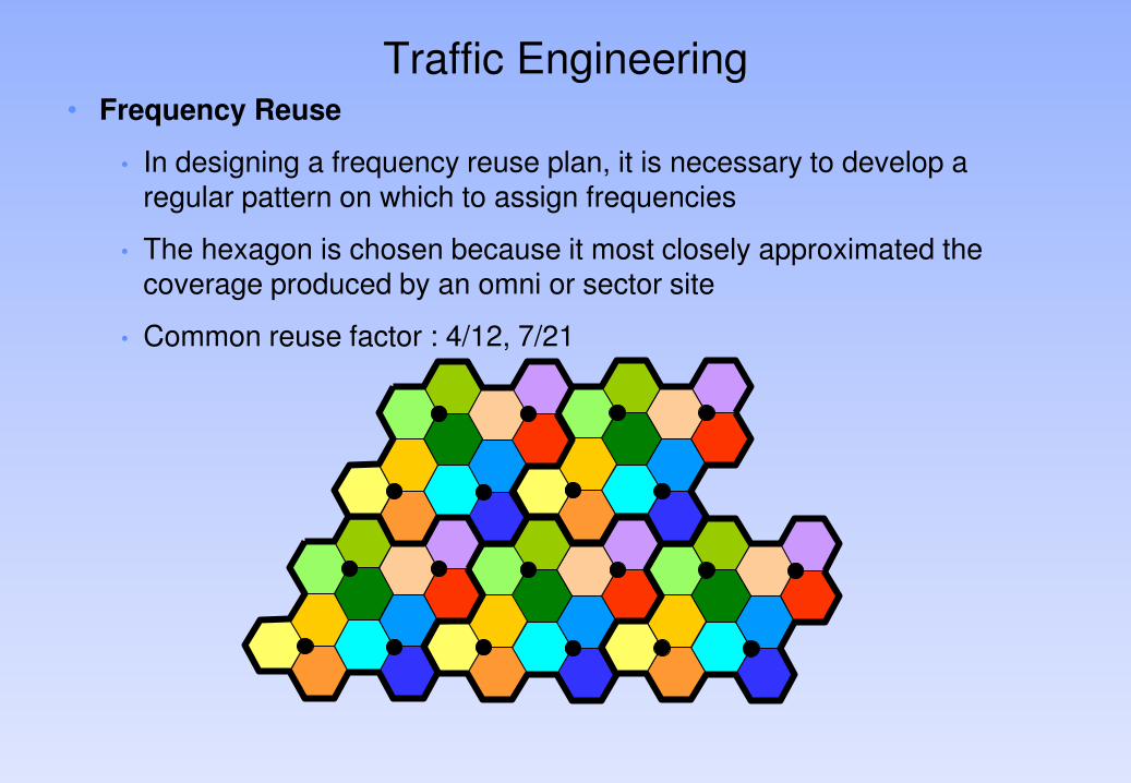
Traffic Engineering • Frequency Reuse
• In designing a frequency reuse plan, it is necessary to develop a regular pattern on which to assign frequencies
• The hexagon is chosen because it most closely approximated the coverage produced by an omni or sector site
• Common reuse factor : 4/12, 7/21
Traffic Engineering
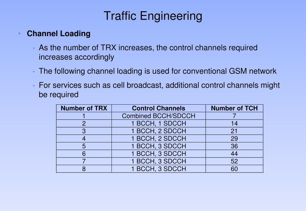
• Channel Loading
• As the number of TRX increases, the control channels required increases accordingly
• The following channel loading is used for conventional GSM network
• For services such as cell broadcast, additional control channels might be required
Number of TRX Control Channels Number of TCH
1 Combined BCCH/SDCCH 7 2 1 BCCH, 1 SDCCH 14 3 1 BCCH, 2 SDCCH 21 4 1 BCCH, 2 SDCCH 29 5 1 BCCH, 3 SDCCH 36 6 1 BCCH, 3 SDCCH 44 7 1 BCCH, 3 SDCCH 52 8 1 BCCH, 3 SDCCH 60

Traffic Engineering
• After determining the number of TCH available and the traffic requirements, the traffic offered is calculated using the Erlang B table
• For example, for a 2% GoS and 3 TRX configuration, the traffic offered is 14
Erlang
• If the traffic per subscriber is 50mE/subscriber, then the total subscribers
supported per sector = 280
• For a uniform traffic distribution network, the number of sites required for the traffic requirement is :-
siteper supportedSubscriber
rs subscribeTotal sitesTotal

Traffic Engineering
• Erlang B Table
N 1% 1.20% 1.50% 2% 3% 5% 7% 10% 15% 20% 30% 40% 50%
1 0.01 0.01 0.02 0.02 0.03 0.05 0.1 0.11 0.18 0.25 0.43 0.67 1
2 0.15 0.17 0.19 0.22 0.28 0.38 0.5 0.6 0.8 1 1.45 2 2.73
3 0.46 0.49 0.54 0.6 0.72 0.9 1.1 1.27 1.6 1.93 2.63 3.48 4.59
4 0.87 0.92 0.99 1.09 1.26 1.52 1.8 2.05 2.5 2.95 3.89 5.02 6.5
5 1.36 1.43 1.52 1.66 1.88 2.22 2.5 2.88 3.45 4.01 5.19 6.6 8.44
6 1.91 2 2.11 2.28 2.54 2.96 3.3 3.76 4.44 5.11 6.51 8.19 10.4
7 2.5 2.6 2.74 2.94 3.25 3.74 4.1 4.67 5.46 6.23 7.86 9.8 12.4
8 3.13 3.25 3.4 3.63 3.99 4.54 5 5.6 6.5 7.37 9.21 11.4 14.3
9 3.78 3.92 4.09 4.34 4.75 5.37 5.9 6.55 7.55 8.52 10.6 13 16.3
10 4.46 4.61 4.81 5.08 5.53 6.22 6.8 7.51 8.62 9.68 12 14.7 18.3
11 5.16 5.32 5.54 5.84 6.33 7.08 7.7 8.49 9.69 10.9 13.3 16.3 20.3
12 5.88 6.05 6.29 6.61 7.14 7.95 8.6 9.47 10.8 12 14.7 18 22.2
13 6.61 6.8 7.05 7.4 7.97 8.83 9.5 10.5 11.9 13.2 16.1 19.6 24.2
14 7.35 7.56 7.82 8.2 8.8 9.73 10.5 11.5 13 14.4 17.5 21.2 26.2
15 8.11 8.33 8.61 9.01 9.65 10.6 11.4 12.5 14.1 15.6 18.9 22.9 28.2
16 8.88 9.11 9.41 9.83 10.5 11.5 12.4 13.5 15.2 16.8 20.3 24.5 30.2
17 9.65 9.89 10.2 10.7 11.4 12.5 13.4 14.5 16.3 18 21.7 26.2 32.2
18 10.4 10.7 11 11.5 12.2 13.4 14.3 15.5 17.4 19.2 23.1 27.8 34.2
19 11.2 11.5 11.8 12.3 13.1 14.3 15.3 16.6 18.5 20.4 24.5 29.5 36.2
20 12 12.3 12.7 13.2 14.0 15.2 16.3 17.6 19.6 21.6 25.9 31.2 38.2
21 12.8 13.1 13.5 14 14.9 16.2 17.3 18.7 20.8 22.8 27.3 32.8 40.2
22 13.7 14 14.3 14.9 15.8 17.1 18.2 19.7 21.9 24.1 28.7 34.5 42.1
23 14.5 14.8 15.2 15.8 16.7 18.1 19.2 20.7 23 25.3 30.1 36.1 44.1

Traffic Engineering
• If a traffic map is provided, the traffic engineering is done together with the coverage design
• After the individual sites are located, the estimated number of subscribers in each sector is calculated by :-
• Calculating the physical area covered by each sector
• Multiply it by the average subscriber density per unit area in that region
• The overlap areas between the sectors should be included in each sector
because either sector is theoretically capable of serving the area
• The number of channels required is then determined by :-
• Calculating the total Erlangs by multiplying the area covered by the average
load generated per subscriber during busy hour
• Determine the required number of TCH and then the required number of TRXs
• If the number of TRXs required exceeded the number of TRXs supported by the available spectrum, additional sites will be required
SWAP PLAN
• Why do we need a swap plan?
To reduce mix of different vendor BTS within a large city/ area • Reduce Inter MSC HO. • Better maintenance efficiency
Swap Strategy • No. of existing BTS sites with configuration known • No. of new sites with configuration known.

Network Planning Steps

Parameter Planning
• Parameter planning means creating a default set of BSS parameters.
• The most important parameters to plan for: • frequencies • BSIC • LAC • handover control parameters • adjacent cell definitions.
BSS Parameter
• Relevant BSS parameter for NW planning
• frequency allocation plan
• transmit power
• definition of neighbouring cells
• definition of location areas
• handover parameters
• power control parameters
• cell selection parameters
Related Documents


![CC - Power Systems · PDF fileIC MIC2807 UMTS EDGE CDMA2000 WCDMA RF Micrel RF ... Turn-off energy / mJ Eoff 40% nominal currentEoff nominal current ... plan ar trench holes [cm-3]](https://static.cupdf.com/doc/110x72/5aae3f097f8b9a07498bdb7d/cc-power-systems-mic2807-umts-edge-cdma2000-wcdma-rf-micrel-rf-turn-off-energy.jpg)


