AIR HANDLERS CBX25UHV (-01) MERIT ® Series R-410A - Upflow / Horizontal - Variable Speed Bulletin No. 210611 March 2015 Supersedes November 2014 Nominal Capacity - 1.5 to 5 Tons Optional Electric Heat - 2.5 to 20 kW CB X 25 UH V - 030 - 230 - 01 Unit Type CB = Air Handler Refrigerant Type X = R-410A Series Nominal Cooling Capacity 018 = 1.5 tons 024 = 2 tons 030 = 2.5 tons 036 = 3 tons 042 = 3.5 tons 048 = 4 tons 060 = 5 tons Minor Revision Number Voltage 230 = 208/230V-1 phase-60hz Configuration UH = Upflow/Horizontal MODEL NUMBER IDENTIFICATION Blower Motor V = Variable Speed PRODUCT SPECIFICATIONS

Welcome message from author
This document is posted to help you gain knowledge. Please leave a comment to let me know what you think about it! Share it to your friends and learn new things together.
Transcript

A I R H A N D L E R S
CBX25UHV (-01)MERIT® Series
R-410A - Upflow / Horizontal - Variable SpeedBulletin No. 210611
March 2015 Supersedes November 2014
Nominal Capacity - 1.5 to 5 TonsOptional Electric Heat - 2.5 to 20 kW
CB X 25 UH V - 030 - 230 - 01
Unit Type CB = Air Handler
Refrigerant Type X = R-410A
Series
Nominal Cooling Capacity 018 = 1.5 tons 024 = 2 tons 030 = 2.5 tons 036 = 3 tons 042 = 3.5 tons 048 = 4 tons 060 = 5 tons
Minor Revision Number
Voltage 230 = 208/230V-1 phase-60hz
Configuration UH = Upflow/Horizontal
MODEL NUMBER IDENTIFICATION
Blower Motor V = Variable Speed
P R O D U C T S P E C I F I C AT I O N S
CBX25UHV 1.5 5 TON UPFLOW/HORIZONTAL AIR HANDLERS
CBX25UHV - 1.5 to 5 ton Air Handlers / Page 2
WARRANTY
All covered components - Limited five years in residential applications, one year in non-residential applications.Refer to Lennox Limited Warranty Certificate included with each unit for additional details.
APPROVALSTested with matching air conditioners and heat pump units in the Lennox Research Laboratory environmental test room in accordance with AHRI Standard 210/240.Optional electric heaters are rated in accordance with US Department of Energy (DOE) test procedures and Federal Trade Commission (FTC) labeling regulations.Air handlers are ETL Listed to US and Canadian safety standards and components within are bonded for grounding to meet safety standards for servicing required by CEC and NEC.ISO 9001 Registered Manufacturing Quality System.
APPLICATIONS1.5 to 5 ton nominal sizes.Upflow or horizontal applications.Compact cabinet height for upflow, horizontal-left or horizontal-right applications.NOTE - Not available for downflow applications.Utility room, alcove, closet, crawl space, basement or attic installation.CBX25UHV models are applicable to R-410A expansion valve systems in cooling applications and check and expansion valve systems in heat pump applications.See bulletins in section Air Conditioners for cooling capacities.See bulletins in section Heat Pump Outdoor Units for cooling and heating capacities.Optional field installed electric heaters available in several sizes for additive heating capacity.
Zoning ApplicationsUnits can be used with certain zoning systems.
A
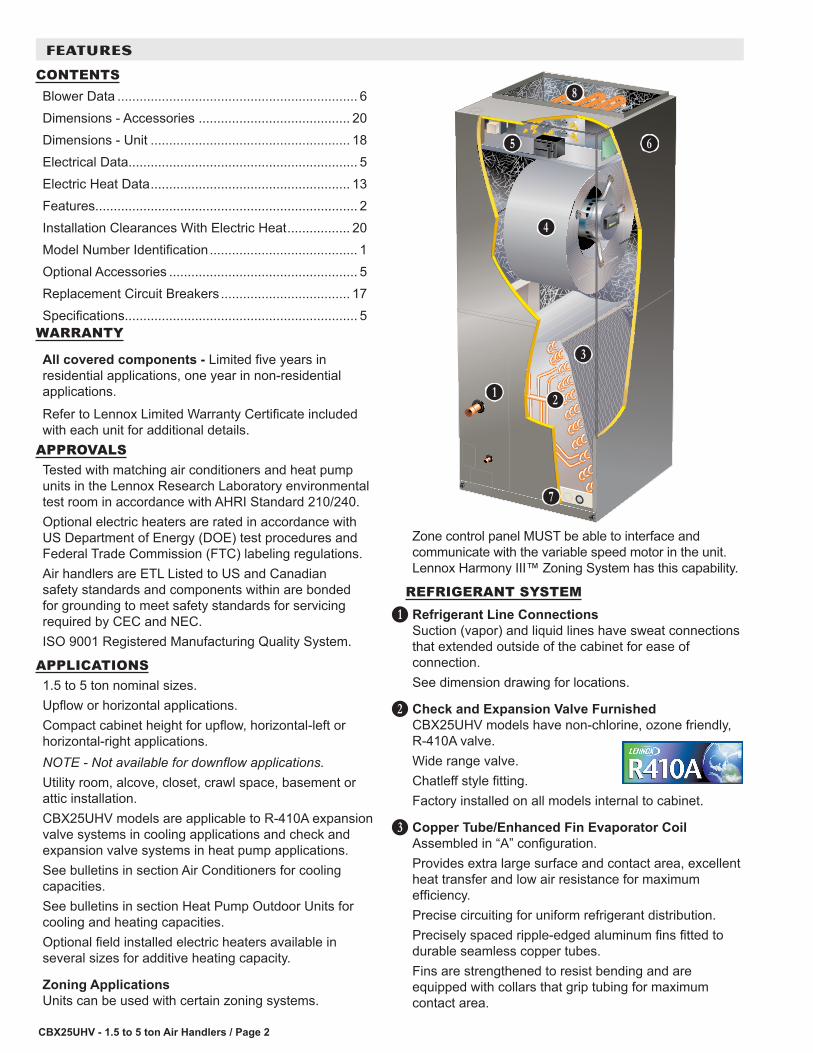
Zone control panel MUST be able to interface and communicate with the variable speed motor in the unit. Lennox Harmony III™ Zoning System has this capability.
REFRIGERANT SYSTEMRefrigerant Line ConnectionsSuction (vapor) and liquid lines have sweat connections that extended outside of the cabinet for ease of connection.See dimension drawing for locations.
Check and Expansion Valve FurnishedCBX25UHV models have non-chlorine, ozone friendly, R-410A valve.Wide range valve.Chatleff style fitting.Factory installed on all models internal to cabinet.
Copper Tube/Enhanced Fin Evaporator CoilAssembled in “A” configuration.Provides extra large surface and contact area, excellent heat transfer and low air resistance for maximum efficiency.Precise circuiting for uniform refrigerant distribution.Precisely spaced ripple-edged aluminum fins fitted to durable seamless copper tubes.Fins are strengthened to resist bending and are equipped with collars that grip tubing for maximum contact area.
B
C
D
B C
D
E
F G
H
I
FEATURES
CONTENTSBlower Data ................................................................. 6Dimensions - Accessories ......................................... 20Dimensions - Unit ...................................................... 18Electrical Data.............................................................. 5Electric Heat Data ...................................................... 13Features....................................................................... 2Installation Clearances With Electric Heat ................. 20Model Number Identification ........................................ 1Optional Accessories ................................................... 5Replacement Circuit Breakers ................................... 17Specifications............................................................... 5

CBX25UHV - 1.5 to 5 ton Air Handlers / Page 3
REFRIGERANT SYSTEM (continued)Lanced fins provide maximum exposure of fin surface to air stream.Long life copper tubing is easy to service.Rifled tubing provides superior heat transfer.Flared shoulder tubing joints and silver soldering provide tight, leakproof joints.Coil thoroughly factory tested under high pressure to insure leakproof construction.
BLOWERProgrammable Multi-Speed Blower MotorHigh efficiency multi-speed blower motor maintains specified air volumes up to a maximum of 0.8 in. w.g. total external static.Programmable multi-speed operation is achieved by the use of an ECM (Electronically Commutated Motor) motor.Allows cooling ramping profiles (field selectable) for enhanced dehumidification.Motor accelerates and decelerates gradually, reducing start-up and shut-down sound.Leadless blower motor features simple plug-in connections.Motor is controlled by BDC3 Electronic Blower Control that allows blower to operate at two of eight air volumes or speeds available.Blower speeds may be field selected on blower control depending on size of air handler and air volume desired.See Blower Data tables.
Blower AssemblyEach blower is statically and dynamically balanced as an assembly before installation in the unit.Blower motor is resiliently mounted to blower assembly.Blower slides out of cabinet for servicing.
CONTROLSBDC3 Electronic Blower ControlControls evaporator humidity by controlling blower and compressor staging on two-stage outdoor units.Two Stages - HEAT and COOL (with four different air volume selections for each) are made by simple jumper pins on board.ADJUST jumper pin allows approximately 10% higher, normal or 10% lower motor speed selection within HEAT and COOL speeds selected for fine tuning air volume.DELAY jumper pin allows selection of four different blower motor de-humidification profiles during cooling mode:
Option 1 - Motor runs at 100% of capacity until demand met. Once demand is met, motor ramps down to stop.
E
Option 2 - Motor runs at 100% until demand is met. Once demand is satisfied, motor runs at 100% for 60 seconds then ramps down to stop.Option 3 - Motor runs at 82% of capacity for approximately 7-1/2 minutes, then 100% capacity (if needed) until demand is satisfied. Once demand is met, motor ramps down to stop.Option 4 - Motor runs at 50% capacity for 30 seconds, then 82% capacity for approximately 7-1/2 minutes. If demand is not satisfied, motor runs at 100% capacity until demand is met. Once demand is met, motor runs at 50% capacity for 30 seconds, then ramps down to stop.Control has two diagnostic indicator lights, “CFM” and “RUN”, to assist in servicing.Accessory relay terminals (24V) provide connections for power humidifiers or powered air cleaners.Control is factory installed in the unit control box.Transformer and Blower Relay for Electric Heat24 volt transformer and blower relay for electric heat furnished as standard.Factory installed in the unit control box.
Optional Accessories
ThermostatSee Thermostat bulletins in Controls section and Lennox Price Book for a complete list of thermostats.
CABINETConstructed of heavy gauge galvanized steel.Powder paint finish.Completely insulated with foil faced fiberglass insulation.Removable panels provide complete service access.Filter access door for easy filter replacement. Thumbscrews secure filter door.Electrical inlets provided in sides and top of cabinet. See dimension drawing for locations.Knock-outs in cabinet for drain connections for upflow (left and right) and horizontal applications. See dimension drawing.
Low Leakage CabinetAll models have less than 2% air leakage and meet ANSI/ASHRAE Standard 193-2010 “Method of Test for Determining the Air Tightness of HVAC Equipment.”
Upflow/Horizontal CapabilityShipped for upflow and horizontal left-hand discharge.May be field converted to horizontal right-hand air discharge by repositioning horizontal drain pan.NOTE - Not available for downflow applications.
F
G
FEATURES

CBX25UHV - 1.5 to 5 ton Air Handlers / Page 4
CABINET (continued)
Anti-Microbial Dual Position Drain PansAnti-Microbial additive resists growth of mold and mildew on drain pan which improves indoor air quality and reduces drain line blockage.Drain pans designed for upflow or horizontal applications.Deep, corrosion resistant high temperature engineered polymer drain pans have dual pipe drains. See dimension drawing.
Optional Accessories
Horizontal Support Frame KitProvides support of unit in horizontal applications.Consists of (2) 1 x 1-1/2 x 32-5/8 in. and (2) 1 x 3 x 53-7/8 in. painted heavy gauge cold rolled steel support channels with assembly and suspending holes.Bolts and nuts furnished for field assembly.Suspending rods must be field provided.
Side Return Unit Stand (Upflow Only)Raises unit 16 in. above floor for side return air duct connection.Eliminates need for wooden platform construction.All aluminum construction.Two adjustable frames fit all sizes.See Dimension Drawing.
Wall Hanging Bracket Kit (Upflow Only)Allows unit to be hung on wall at any height.Consists of heavy gauge steel support brackets (one for air handler unit, one for wall mount).Screws furnished for fastening one bracket to unit.Bolts for fastening one bracket to wall are field provided.
FILTERDisposable 1 inch filter is furnished.Filter rack furnished in cabinet for easy filter installation.See Specifications tables for filter sizes.
H
FEATURES
ELECTRICAL
Optional Accessories
Electric HeatField install internal to unit cabinet.Available in several kW sizes.See Electric Heat tables.Helix wound nichrome heating elements exposed directly in air stream resulting in instant heat transfer, low element temperatures and long service life.Each element equipped with accurately located limit control with fixed temperature off setting and automatic reset.Thermal sequencer relay brings elements on and off line, in sequence and equal increments, with time delay between each.Initiates and terminates blower operation.Heating control relay(s) furnished as standard.Factory assembled with controls installed and wired.Electric heat control wiring plugs into mating connector on air handler unit.
Circuit Breaker ModelsECB25-5CB, ECB25-7.5CB, ECB25-10CB, ECB25-12.5, ECB25-15CB, ECB25-20CB heaters are equipped with circuit breakers for overload and short circuit protection.Factory wired and mounted on electric heat unit.Current sensitive and temperature actuated.Manual reset.Flexible plastic circuit breaker cover protects circuit breaker in areas with high humidity or unconditioned areas to prevent nuisance tripping.Circuit breakers qualify as disconnect means at unit in many areas, eliminate the need for field provided disconnect.Consult local electrical code in your area.
Single-point Power Source Control BoxControl Box may be used with optional electric heat when single power supply is connected to multi-circuit electric heat.Field installs external to the unit cabinet on either side or top.Constructed of heavy gauge steel, baked enamel finish, prepunched mounting holes, electrical inlet knockouts, and terminal strip.Removable cover provides easy access.Dimensions (H x W x D) - 7 x 7 x 4 in.
I

CBX25UHV - 1.5 to 5 ton Air Handlers / Page 5
SPECIFICATIONSGeneral Data
Model Number CBX25UHV-018 CBX25UHV-024 CBX25UHV-030 CBX25UHV-036Nominal tonnage 1.5 2 2.5 3
Connections Suction/Vapor line (o.d.) - in. sweat 3/4 3/4 7/8 7/8Liquid line (o.d.) - in. sweat 3/8 3/8 3/8 3/8
Condensate - in. fpt (2) 3/4 (2) 3/4 (2) 3/4 (2) 3/4Indoor Coil
Net face area - ft.2 3.11 3.56 4.00 4.89Tube outside diameter - in. 3/8 3/8 3/8 3/8
Number of rows 3 3 3 3Fins per inch 14 14 14 14
Blower Wheel nominal diameter x width - in. 9 x 6 9 x 6 10 x 8 10 x 8Blower motor output - hp 1/2 1/2 1/2 1/2
1 Filters Size of filter - in. 12 x 20 x 1 15 x 20 x 1 15 x 20 x 1 18 x 20 x 1
ELECTRICAL DATAVoltage - 1 phase (60 hz) 208/240V 208/240V 208/240V 208/240V
2 Maximum overcurrent protection (unit only) 15 15 15 153 Minimum circuit ampacity (unit only) 4.9 4.9 4.9 4.9
Blower Motor Full Load Amps 3.9 3.9 3.9 3.9Shipping Data -1 package - lbs. 105 123 126 161
SPECIFICATIONSGeneral Data
Model Number CBX25UHV-042 CBX25UHV-048 CBX25UHV-060Nominal tonnage 3.5 4 5
Connections Suction/Vapor line (o.d.) - in. sweat 7/8 7/8 7/8Liquid line (o.d.) - in. sweat 3/8 3/8 3/8
Condensate - in. fpt (2) 3/4 (2) 3/4 (2) 3/4Indoor Coil
Net face area - ft.2 5.83 7.00 7.00Tube outside diameter - in. 3/8 3/8 3/8
Number of rows 3 3 3Fins per inch 14 14 14
Blower Wheel nominal diameter x width - in. 12 x 8 12 x 9 12 x 9Blower motor output - hp 3/4 1 1
1 Filters Size of filter - in. 18 x 24 x 1 18 x 24 x 1 18 x 24 x 1
ELECTRICAL DATAVoltage - 1 phase (60 hz) 208/240V 208/240V 208/240V
2 Maximum overcurrent protection (unit only) 15 15 153 Minimum circuit ampacity (unit only) 6.5 8.6 8.6
Blower Motor Full Load Amps 5.2 6.9 6.9Shipping Data -1 package - lbs. 163 186 1861 Disposable filter.2 HACR type circuit breaker or fuse.3 Refer to National or Canadian Electrical Code manual to determine wire, fuse and disconnect size requirements. Use wires suitable for at least 167°F.
OPTIONAL ACCESSORIES - ORDER SEPARATELYModel -018 -024
-030-036 -042
-048 -060
Horizontal Support Frame Kit 56J18 56J18 56J18 56J18
Side Return Unit Stand (Upflow Only) 45K31 45K32 45K32 45K32
Single-Point Power Source Control Box (for Electric Heat) 21H39 21H39 21H39 21H39
Wall Hanging Bracket Kit (Upflow Only) 45K30 45K30 45K30 45K30NOTE - Not available for downflow applications.
CBX25UHV - 1.5 to 5 ton Air Handlers / Page 6
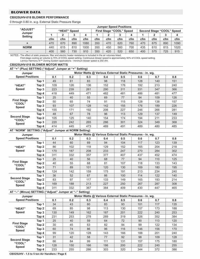
BLOWER DATACBX25UHV-018 BLOWER PERFORMANCE0 through 0.80 in. w.g. External Static Pressure Range
“ADJUST” Jumper Setting
Jumper Speed Positions“HEAT” Speed First Stage “COOL” Speed Second Stage “COOL” Speed
1 2 3 4 1 2 3 4 1 2 3 4cfm cfm cfm cfm cfm cfm cfm cfm cfm cfm cfm cfm
+ 470 670 890 1080 350 470 620 760 470 675 890 1090NORM 440 615 810 1000 350 450 560 700 435 610 815 1020
– 400 560 730 910 350 420 520 650 400 575 725 915NOTES - The effect of static pressure, filter and electric heater resistance is included in the air volumes listed.
First stage cooling air volume is 70% of COOL speed setting. Continuous blower speed is approximately 50% of COOL speed setting. Lennox Harmony III™ Zoning System applications - minimum blower speed is 250 cfm.
CBX25UHV-018 BLOWER MOTOR WATTSAT “+” (Plus) SETTING (“Adjust” Jumper at “+” Setting)
Jumper Speed Positions
Motor Watts @ Various External Static Pressures - in. wg.0.1 0.2 0.3 0.4 0.5 0.6 0.7 0.8
“HEAT” Speed
Tap 1 49 61 83 98 118 128 140 151Tap 2 109 126 136 152 176 192 213 240Tap 3 223 239 261 290 311 331 347 366Tap 4 418 449 471 482 481 486 481 477
First Stage “COOL” Speed
Tap 1 25 40 55 69 77 94 109 126Tap 2 50 65 74 91 115 128 138 157Tap 3 93 107 128 142 155 176 189 226Tap 4 155 171 192 206 227 246 266 281
Second Stage “COOL” Speed
Tap 1 48 67 78 96 113 129 137 149Tap 2 105 125 140 154 174 194 211 233Tap 3 220 242 265 286 301 324 349 368Tap 4 414 445 473 489 491 489 480 485
AT “NORM” SETTING (“Adjust” Jumper at NORM Setting)Jumper
Speed PositionsMotor Watts @ Various External Static Pressures - in. wg.
0.1 0.2 0.3 0.4 0.5 0.6 0.7 0.8
“HEAT” Speed
Tap 1 44 60 69 94 104 117 123 139Tap 2 86 102 118 129 152 165 204 218Tap 3 170 187 208 233 247 270 284 302Tap 4 311 332 357 377 407 437 452 474
First Stage “COOL” Speed
Tap 1 25 40 56 68 77 94 110 125Tap 2 40 55 68 81 107 118 133 143Tap 3 71 89 101 120 130 169 180 195Tap 4 124 142 159 175 191 213 234 240
Second Stage “COOL” Speed
Tap 1 36 52 67 86 100 114 122 140Tap 2 83 97 117 133 149 165 193 214Tap 3 169 188 213 227 250 267 287 308Tap 4 311 332 367 384 409 430 447 465
AT “–” (Minus) SETTING (“Adjust” Jumper at “–” Setting)Jumper
Speed PositionsMotor Watts @ Various External Static Pressures - in. wg.
0.1 0.2 0.3 0.4 0.5 0.6 0.7 0.8
“HEAT” Speed
Tap 1 34 43 60 83 93 101 117 135Tap 2 69 85 98 113 130 157 173 188Tap 3 130 149 162 187 201 222 240 253Tap 4 231 253 278 289 319 326 352 384
First Stage “COOL” Speed
Tap 1 25 40 59 64 72 90 113 120Tap 2 30 45 63 82 94 99 122 134Tap 3 60 74 86 96 116 146 156 170Tap 4 99 120 128 143 166 188 201 240
Second Stage “COOL” Speed
Tap 1 31 42 58 77 92 98 109 128Tap 2 66 84 99 111 131 157 175 180Tap 3 128 150 166 186 200 222 240 255Tap 4 233 255 286 303 320 344 372 386

CBX25UHV - 1.5 to 5 ton Air Handlers / Page 7
BLOWER DATACBX25UHV-024 BLOWER PERFORMANCE0 through 0.80 in. w.g. External Static Pressure Range
“ADJUST” Jumper Setting
Jumper Speed Positions“HEAT” Speed First Stage “COOL” Speed Second Stage “COOL” Speed
1 2 3 4 1 2 3 4 1 2 3 4cfm cfm cfm cfm cfm cfm cfm cfm cfm cfm cfm cfm
+ 470 690 900 1120 350 470 625 775 480 670 890 1125NORM 430 640 810 1020 330 450 580 720 430 605 820 1020
– 410 550 720 900 300 405 505 650 390 545 740 930NOTES - The effect of static pressure, filter and electric heater resistance is included in the air volumes listed.
First stage cooling air volume is 70% of COOL speed setting. Continuous blower speed is approximately 50% of COOL speed setting. Lennox Harmony III™ Zoning System applications - minimum blower speed is 250 cfm.
CBX25UHV-024 BLOWER MOTOR WATTSAT “+” (Plus) SETTING (“Adjust” Jumper at “+” Setting)
Jumper Speed Positions
Motor Watts @ Various External Static Pressures - in. wg.0.1 0.2 0.3 0.4 0.5 0.6 0.7 0.8
“HEAT” Speed
Tap 1 49 64 79 94 109 125 141 157Tap 2 66 88 109 131 146 170 188 217Tap 3 145 172 188 217 239 266 289 314Tap 4 271 299 332 362 377 405 421 456
First Stage “COOL” Speed
Tap 1 15 23 37 52 72 92 101 117Tap 2 27 52 62 87 113 130 144 159Tap 3 66 82 101 123 138 158 185 217Tap 4 105 123 148 170 187 211 232 262
Second Stage “COOL” Speed
Tap 1 45 62 75 90 104 118 137 153Tap 2 64 86 111 129 148 168 198 228Tap 3 146 174 195 217 242 263 291 316Tap 4 274 289 325 362 367 407 434 466
AT “NORM” SETTING (“Adjust” Jumper at NORM Setting)Jumper
Speed PositionsMotor Watts @ Various External Static Pressures - in. wg.
0.1 0.2 0.3 0.4 0.5 0.6 0.7 0.8
“HEAT” Speed
Tap 1 30 43 59 76 96 112 124 145Tap 2 52 75 88 111 131 151 181 209Tap 3 111 135 157 177 198 224 250 264Tap 4 204 231 259 278 308 324 356 381
First Stage “COOL” Speed
Tap 1 12 20 30 45 64 84 110 119Tap 2 25 46 60 81 99 113 136 150Tap 3 45 59 85 96 115 144 170 189Tap 4 75 97 122 144 161 183 206 226
Second Stage “COOL” Speed
Tap 1 31 44 60 77 94 111 120 139Tap 2 50 74 92 108 129 151 174 206Tap 3 115 134 159 180 206 228 249 267Tap 4 210 232 267 284 309 335 364 384
AT “–” (Minus) SETTING (“Adjust” Jumper at “–” Setting)Jumper
Speed PositionsMotor Watts @ Various External Static Pressures - in. wg.
0.1 0.2 0.3 0.4 0.5 0.6 0.7 0.8
“HEAT” Speed
Tap 1 22 30 45 62 84 106 117 130Tap 2 44 57 80 98 114 139 173 183Tap 3 87 108 122 149 170 181 207 228Tap 4 153 180 202 232 239 275 301 320
First Stage “COOL” Speed
Tap 1 8 15 26 41 59 74 98 112Tap 2 23 44 59 75 91 104 122 140Tap 3 29 48 69 89 119 128 142 178Tap 4 58 77 97 118 136 155 180 216
Second Stage “COOL” Speed
Tap 1 22 30 45 61 83 96 116 128Tap 2 41 58 80 99 114 146 170 189Tap 3 81 103 125 150 170 188 209 232Tap 4 150 176 201 222 245 272 291 320

CBX25UHV - 1.5 to 5 ton Air Handlers / Page 8
BLOWER DATACBX25UHV-030 BLOWER PERFORMANCE0 through 0.80 in. w.g. External Static Pressure Range
“ADJUST” Jumper Setting
Jumper Speed Positions“HEAT” Speed First Stage “COOL” Speed Second Stage “COOL” Speed
1 2 3 4 1 2 3 4 1 2 3 4cfm cfm cfm cfm cfm cfm cfm cfm cfm cfm cfm cfm
+ 650 900 1100 1320 430 600 740 920 650 875 1100 1330NORM 590 795 1000 1200 390 550 680 830 580 800 1000 1200
– 520 730 895 1075 340 475 620 750 500 700 900 1090NOTES - The effect of static pressure, filter and electric heater resistance is included in the air volumes listed.
First stage cooling air volume is 70% of COOL speed setting. Continuous blower speed is approximately 50% of COOL speed setting. Lennox Harmony III™ Zoning System applications - minimum blower speed is 250 cfm.
CBX25UHV-030 BLOWER MOTOR WATTSAT “+” (Plus) SETTING (“Adjust” Jumper at “+” Setting)
Jumper Speed Positions
Motor Watts @ Various External Static Pressures - in. wg.0.1 0.2 0.3 0.4 0.5 0.6 0.7 0.8
“HEAT” Speed
Tap 1 45 75 97 116 139 156 180 197Tap 2 113 137 164 189 210 232 258 285Tap 3 198 228 261 275 313 348 373 409Tap 4 321 358 387 417 456 493 523 513
First Stage “COOL” Speed
Tap 1 23 43 63 73 87 107 129 143Tap 2 39 65 105 110 126 144 155 169Tap 3 73 101 126 144 160 192 213 232Tap 4 117 140 170 197 219 245 268 297
Second Stage “COOL” Speed
Tap 1 42 75 97 119 139 153 173 189Tap 2 113 138 161 187 206 230 255 291Tap 3 197 216 241 283 309 343 371 397Tap 4 323 350 386 421 458 476 519 510
AT “NORM” SETTING (“Adjust” Jumper at NORM Setting)Jumper
Speed PositionsMotor Watts @ Various External Static Pressures - in. wg.
0.1 0.2 0.3 0.4 0.5 0.6 0.7 0.8
“HEAT” Speed
Tap 1 33 58 85 109 123 141 158 173Tap 2 86 109 141 161 175 198 228 258Tap 3 150 180 210 240 267 294 312 341Tap 4 252 274 294 333 375 398 432 467
First Stage “COOL” Speed
Tap 1 18 30 44 64 86 104 116 139Tap 2 29 56 71 90 110 125 139 157Tap 3 55 84 106 124 147 173 188 206Tap 4 95 122 144 172 191 214 246 270
Second Stage “COOL” Speed
Tap 1 37 55 79 98 120 141 155 171Tap 2 85 107 134 155 176 198 228 251Tap 3 151 170 201 229 255 279 311 340Tap 4 249 276 304 338 371 405 442 465
AT “–” (Minus) SETTING (“Adjust” Jumper at “–” Setting)Jumper
Speed PositionsMotor Watts @ Various External Static Pressures - in. wg.
0.1 0.2 0.3 0.4 0.5 0.6 0.7 0.8
“HEAT” Speed
Tap 1 27 52 70 92 110 124 135 157Tap 2 68 93 111 129 152 182 199 215Tap 3 113 139 168 179 205 238 261 299Tap 4 185 207 231 273 290 321 347 382
First Stage “COOL” Speed
Tap 1 15 26 40 59 78 99 109 127Tap 2 23 42 63 82 92 110 130 150Tap 3 45 68 91 110 134 154 165 178Tap 4 71 104 121 144 163 190 220 237
Second Stage “COOL” Speed
Tap 1 26 49 64 83 108 125 134 149Tap 2 60 88 116 131 151 182 197 208Tap 3 115 135 162 192 212 240 268 287Tap 4 186 211 236 268 304 328 346 380

CBX25UHV - 1.5 to 5 ton Air Handlers / Page 9
BLOWER DATACBX25UHV-036 BLOWER PERFORMANCE0 through 0.80 in. w.g. External Static Pressure Range
“ADJUST” Jumper Setting
Jumper Speed Positions“HEAT” Speed First Stage “COOL” Speed Second Stage “COOL” Speed
1 2 3 4 1 2 3 4 1 2 3 4cfm cfm cfm cfm cfm cfm cfm cfm cfm cfm cfm cfm
+ 880 1115 1345 1435 615 770 930 1090 880 1110 1340 1435NORM 800 1010 1215 1425 555 695 845 990 795 1005 1215 1420
– 715 905 1095 1275 505 625 755 885 715 905 1090 1280NOTES - The effect of static pressure, filter and electric heater resistance is included in the air volumes listed.
First stage cooling air volume is 70% of COOL speed setting. Continuous blower speed is approximately 50% of COOL speed setting. Lennox Harmony III™ Zoning System applications - minimum blower speed is 250 cfm.
CBX25UHV-036 BLOWER MOTOR WATTSAT “+” (Plus) SETTING (“Adjust” Jumper at “+” Setting)
Jumper Speed Positions
Motor Watts @ Various External Static Pressures - in. wg.0.1 0.2 0.3 0.4 0.5 0.6 0.7 0.8
“HEAT” Speed
Tap 1 111 130 151 175 198 218 241 263Tap 2 190 215 242 272 297 327 354 379Tap 3 310 339 374 409 442 474 505 512Tap 4 491 520 512 511 515 518 515 512
First Stage “COOL” Speed
Tap 1 55 71 88 107 124 140 156 171Tap 2 84 101 120 143 162 182 202 220Tap 3 124 145 167 193 215 237 259 283Tap 4 180 204 231 258 283 310 338 363
Second Stage “COOL” Speed
Tap 1 110 130 151 176 198 218 240 262Tap 2 190 213 240 269 297 324 351 374Tap 3 311 339 373 407 440 472 503 512Tap 4 487 521 514 513 516 519 517 514
AT “NORM” SETTING (“Adjust” Jumper at NORM Setting)Jumper
Speed PositionsMotor Watts @ Various External Static Pressures - in. wg.
0.1 0.2 0.3 0.4 0.5 0.6 0.7 0.8
“HEAT” Speed
Tap 1 90 108 127 151 170 192 211 229Tap 2 151 171 195 223 247 271 294 318Tap 3 236 264 294 327 356 384 415 445Tap 4 370 400 436 473 509 518 515 512
First Stage “COOL” Speed
Tap 1 46 61 78 95 112 126 140 155Tap 2 71 85 104 124 143 161 178 196Tap 3 101 119 140 163 185 206 227 247Tap 4 141 162 187 213 239 258 280 309
Second Stage “COOL” Speed
Tap 1 91 108 128 151 171 191 212 230Tap 2 148 171 196 223 247 273 297 318Tap 3 241 265 295 327 356 384 413 443Tap 4 369 396 432 472 508 519 516 513
AT “–” (Minus) SETTING (“Adjust” Jumper at “–” Setting)Jumper
Speed PositionsMotor Watts @ Various External Static Pressures - in. wg.
0.1 0.2 0.3 0.4 0.5 0.6 0.7 0.8
“HEAT” Speed
Tap 1 73 89 108 128 148 165 184 202Tap 2 116 136 159 184 207 228 251 272Tap 3 184 206 232 261 288 315 340 366Tap 4 274 298 332 366 397 427 457 484
First Stage “COOL” Speed
Tap 1 40 54 69 86 101 115 128 142Tap 2 57 72 90 109 126 143 159 174Tap 3 81 98 117 139 158 177 196 215Tap 4 111 131 152 177 200 220 242 264
Second Stage “COOL” Speed
Tap 1 73 89 109 129 149 167 184 203Tap 2 118 137 159 183 208 228 250 272Tap 3 181 203 230 259 284 311 339 363Tap 4 272 298 332 366 397 428 458 490
CBX25UHV - 1.5 to 5 ton Air Handlers / Page 10
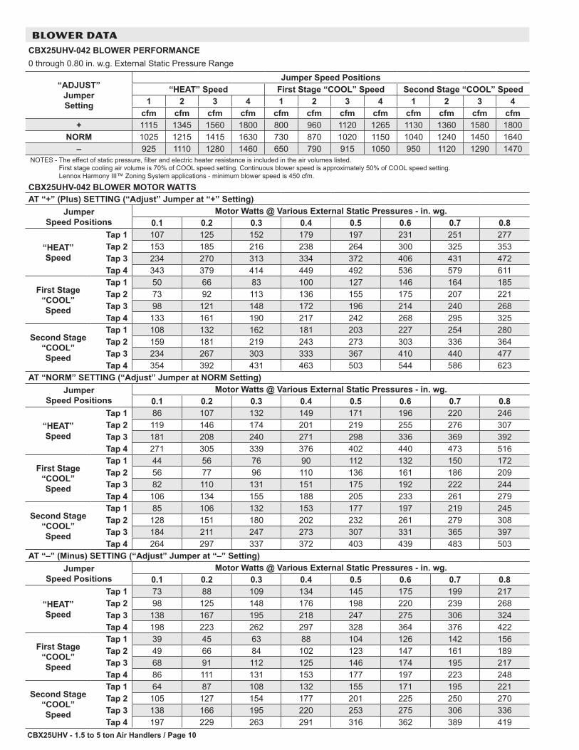
BLOWER DATACBX25UHV-042 BLOWER PERFORMANCE0 through 0.80 in. w.g. External Static Pressure Range
“ADJUST” Jumper Setting
Jumper Speed Positions“HEAT” Speed First Stage “COOL” Speed Second Stage “COOL” Speed
1 2 3 4 1 2 3 4 1 2 3 4cfm cfm cfm cfm cfm cfm cfm cfm cfm cfm cfm cfm
+ 1115 1345 1560 1800 800 960 1120 1265 1130 1360 1580 1800NORM 1025 1215 1415 1630 730 870 1020 1150 1040 1240 1450 1640
– 925 1110 1280 1460 650 790 915 1050 950 1120 1290 1470NOTES - The effect of static pressure, filter and electric heater resistance is included in the air volumes listed.
First stage cooling air volume is 70% of COOL speed setting. Continuous blower speed is approximately 50% of COOL speed setting. Lennox Harmony III™ Zoning System applications - minimum blower speed is 450 cfm.
CBX25UHV-042 BLOWER MOTOR WATTSAT “+” (Plus) SETTING (“Adjust” Jumper at “+” Setting)
Jumper Speed Positions
Motor Watts @ Various External Static Pressures - in. wg.0.1 0.2 0.3 0.4 0.5 0.6 0.7 0.8
“HEAT” Speed
Tap 1 107 125 152 179 197 231 251 277Tap 2 153 185 216 238 264 300 325 353Tap 3 234 270 313 334 372 406 431 472Tap 4 343 379 414 449 492 536 579 611
First Stage “COOL” Speed
Tap 1 50 66 83 100 127 146 164 185Tap 2 73 92 113 136 155 175 207 221Tap 3 98 121 148 172 196 214 240 268Tap 4 133 161 190 217 242 268 295 325
Second Stage “COOL” Speed
Tap 1 108 132 162 181 203 227 254 280Tap 2 159 181 219 243 273 303 336 364Tap 3 234 267 303 333 367 410 440 477Tap 4 354 392 431 463 503 544 586 623
AT “NORM” SETTING (“Adjust” Jumper at NORM Setting)Jumper
Speed PositionsMotor Watts @ Various External Static Pressures - in. wg.
0.1 0.2 0.3 0.4 0.5 0.6 0.7 0.8
“HEAT” Speed
Tap 1 86 107 132 149 171 196 220 246Tap 2 119 146 174 201 219 255 276 307Tap 3 181 208 240 271 298 336 369 392Tap 4 271 305 339 376 402 440 473 516
First Stage “COOL” Speed
Tap 1 44 56 76 90 112 132 150 172Tap 2 56 77 96 110 136 161 186 209Tap 3 82 110 131 151 175 192 222 244Tap 4 106 134 155 188 205 233 261 279
Second Stage “COOL” Speed
Tap 1 85 106 132 153 177 197 219 245Tap 2 128 151 180 202 232 261 279 308Tap 3 184 211 247 273 307 331 365 397Tap 4 264 297 337 372 403 439 483 503
AT “–” (Minus) SETTING (“Adjust” Jumper at “–” Setting)Jumper
Speed PositionsMotor Watts @ Various External Static Pressures - in. wg.
0.1 0.2 0.3 0.4 0.5 0.6 0.7 0.8
“HEAT” Speed
Tap 1 73 88 109 134 145 175 199 217Tap 2 98 125 148 176 198 220 239 268Tap 3 138 167 195 218 247 275 306 324Tap 4 198 223 262 297 328 364 376 422
First Stage “COOL” Speed
Tap 1 39 45 63 88 104 126 142 156Tap 2 49 66 84 102 123 147 161 189Tap 3 68 91 112 125 146 174 195 217Tap 4 86 111 131 153 177 197 223 248
Second Stage “COOL” Speed
Tap 1 64 87 108 132 155 171 195 221Tap 2 105 127 154 177 201 225 250 270Tap 3 138 166 195 220 253 275 306 336Tap 4 197 229 263 291 316 362 389 419

CBX25UHV - 1.5 to 5 ton Air Handlers / Page 11
BLOWER DATACBX25UHV-048 BLOWER PERFORMANCE0 through 0.80 in. w.g. External Static Pressure Range
“ADJUST” Jumper Setting
Jumper Speed Positions“HEAT” Speed First Stage “COOL” Speed Second Stage “COOL” Speed
1 2 3 4 1 2 3 4 1 2 3 4cfm cfm cfm cfm cfm cfm cfm cfm cfm cfm cfm cfm
+ 1450 1670 1880 2340 1050 1200 1340 1650 1440 1670 1950 2340NORM 1340 1520 1730 2100 950 1100 1230 1520 1325 1530 1740 2150
– 1210 1390 1570 1915 850 1000 1110 1375 1200 1380 1600 1950NOTES - The effect of static pressure, filter and electric heater resistance is included in the air volumes listed.
First stage cooling air volume is 70% of COOL speed setting. Continuous blower speed is approximately 50% of COOL speed setting. Lennox Harmony III™ Zoning System applications - minimum blower speed is 450 cfm.
CBX25UHV-048 BLOWER MOTOR WATTSAT “+” (Plus) SETTING (“Adjust” Jumper at “+” Setting)
Jumper Speed Positions
Motor Watts @ Various External Static Pressures - in. wg.0.1 0.2 0.3 0.4 0.5 0.6 0.7 0.8
“HEAT” Speed
Tap 1 196 222 269 295 334 363 386 429Tap 2 282 317 373 403 440 486 512 545Tap 3 409 442 484 528 582 619 661 714Tap 4 824 851 891 936 1,024 980 1,000 993
First Stage “COOL” Speed
Tap 1 91 116 146 166 189 213 243 267Tap 2 110 148 173 205 232 261 280 309Tap 3 160 201 227 253 286 316 348 374Tap 4 270 314 358 397 440 476 516 536
Second Stage “COOL” Speed
Tap 1 200 231 265 298 337 354 383 425Tap 2 293 333 380 421 448 487 519 560Tap 3 403 441 489 546 589 639 678 717Tap 4 778 806 896 943 1,000 999 981 986
AT “NORM” SETTING (“Adjust” Jumper at NORM Setting)Jumper
Speed PositionsMotor Watts @ Various External Static Pressures - in. wg.
0.1 0.2 0.3 0.4 0.5 0.6 0.7 0.8
“HEAT” Speed
Tap 1 151 185 215 251 283 316 347 369Tap 2 219 258 300 328 371 407 439 473Tap 3 315 360 414 450 489 523 562 607Tap 4 572 604 690 732 774 826 856 913
First Stage “COOL” Speed
Tap 1 76 99 121 139 165 199 221 243Tap 2 106 124 150 172 199 226 255 279Tap 3 125 162 195 222 255 281 306 330Tap 4 223 247 299 317 353 390 430 458
Second Stage “COOL” Speed
Tap 1 147 188 222 250 281 309 340 367Tap 2 224 274 306 347 374 415 441 482Tap 3 301 347 399 443 470 525 550 597Tap 4 581 629 678 742 795 843 900 959
AT “–” (Minus) SETTING (“Adjust” Jumper at “–” Setting)Jumper
Speed PositionsMotor Watts @ Various External Static Pressures - in. wg.
0.1 0.2 0.3 0.4 0.5 0.6 0.7 0.8
“HEAT” Speed
Tap 1 115 154 183 209 230 264 283 318Tap 2 170 210 238 269 307 340 363 397Tap 3 238 282 321 352 394 416 455 496Tap 4 416 469 522 569 609 648 695 741
First Stage “COOL” Speed
Tap 1 58 82 101 126 144 168 196 231Tap 2 80 110 139 151 178 201 225 258Tap 3 99 129 154 180 205 227 258 290Tap 4 179 218 248 284 308 349 377 394
Second Stage “COOL” Speed
Tap 1 115 153 178 204 234 258 285 306Tap 2 175 214 244 271 310 340 370 398Tap 3 244 285 338 372 408 429 467 501Tap 4 421 461 520 563 619 665 700 748

CBX25UHV - 1.5 to 5 ton Air Handlers / Page 12
BLOWER DATACBX25UHV-060 BLOWER PERFORMANCE0 through 0.80 in. w.g. External Static Pressure Range
“ADJUST” Jumper Setting
Jumper Speed Positions“HEAT” Speed First Stage “COOL” Speed Second Stage “COOL” Speed
1 2 3 4 1 2 3 4 1 2 3 4cfm cfm cfm cfm cfm cfm cfm cfm cfm cfm cfm cfm
+ 1700 1930 2120 2275 1225 1410 1530 1690 1720 1930 2140 2270NORM 1570 1760 1925 2100 1120 1260 1400 1540 1580 1765 1970 2100
– 1420 1595 1760 1920 1015 1160 1275 1390 1430 1625 1780 1890NOTES - The effect of static pressure, filter and electric heater resistance is included in the air volumes listed.
First stage cooling air volume is 70% of COOL speed setting. Continuous blower speed is approximately 50% of COOL speed setting. Lennox Harmony III™ Zoning System applications - minimum blower speed is 450 cfm.
CBX25UHV-060 BLOWER MOTOR WATTSAT “+” (Plus) SETTING (“Adjust” Jumper at “+” Setting)
Jumper Speed Positions
Motor Watts @ Various External Static Pressures - in. wg.0.1 0.2 0.3 0.4 0.5 0.6 0.7 0.8
“HEAT” Speed
Tap 1 309 354 391 431 463 507 545 564Tap 2 456 503 556 600 642 682 718 744Tap 3 612 672 732 783 819 874 918 949Tap 4 812 859 917 972 988 981 947 939
First Stage “COOL” Speed
Tap 1 125 151 187 216 237 276 312 359Tap 2 170 210 243 277 307 342 371 410Tap 3 234 271 307 342 385 408 440 470Tap 4 301 348 386 422 460 489 532 561
Second Stage “COOL” Speed
Tap 1 313 363 409 429 484 509 553 594Tap 2 461 510 552 602 633 677 731 750Tap 3 607 660 713 765 802 857 891 937Tap 4 778 834 898 943 1,005 968 949 950
AT “NORM” SETTING (“Adjust” Jumper at NORM Setting)Jumper
Speed PositionsMotor Watts @ Various External Static Pressures - in. wg.
0.1 0.2 0.3 0.4 0.5 0.6 0.7 0.8
“HEAT” Speed
Tap 1 234 274 315 353 385 417 451 490Tap 2 331 387 412 473 515 545 571 617Tap 3 477 508 561 611 649 693 717 765Tap 4 593 631 703 751 821 833 875 930
First Stage “COOL” Speed
Tap 1 98 127 150 172 178 244 285 316Tap 2 124 162 186 228 247 287 330 373Tap 3 175 207 246 280 310 338 374 427Tap 4 224 270 306 342 368 416 467 467
Second Stage “COOL” Speed
Tap 1 246 289 330 363 400 428 472 512Tap 2 358 399 442 467 503 559 601 633Tap 3 490 546 584 636 671 680 765 806Tap 4 568 623 674 732 787 838 878 925
AT “–” (Minus) SETTING (“Adjust” Jumper at “–” Setting)Jumper
Speed PositionsMotor Watts @ Various External Static Pressures - in. wg.
0.1 0.2 0.3 0.4 0.5 0.6 0.7 0.8
“HEAT” Speed
Tap 1 177 215 249 289 312 349 389 411Tap 2 260 293 340 369 409 438 486 518Tap 3 349 389 446 476 513 558 587 633Tap 4 436 498 528 592 635 658 702 737
First Stage “COOL” Speed
Tap 1 64 86 123 157 189 219 250 278Tap 2 101 137 159 189 228 278 288 328Tap 3 136 165 194 219 259 297 316 374Tap 4 171 211 240 278 308 334 367 402
Second Stage “COOL” Speed
Tap 1 200 231 259 294 319 365 385 436Tap 2 265 300 349 384 414 458 496 531Tap 3 357 398 442 487 527 563 604 637Tap 4 429 485 531 573 605 664 686 740
CBX25UHV - 1.5 to 5 ton Air Handlers / Page 13
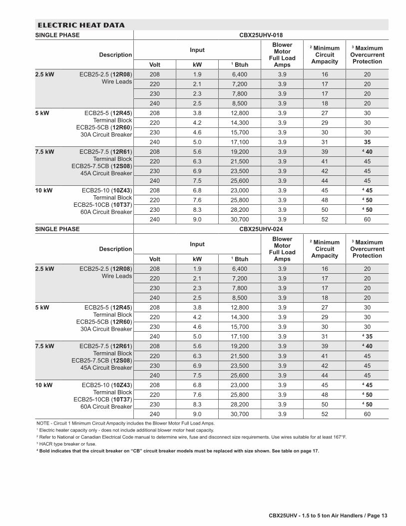
ELECTRIC HEAT DATASINGLE PHASE CBX25UHV-018
DescriptionInput
Blower Motor
Full Load Amps
2 Minimum Circuit
Ampacity
3 Maximum Overcurrent ProtectionVolt kW 1 Btuh
2.5 kW ECB25-2.5 (12R08) Wire Leads
208 1.9 6,400 3.9 16 20220 2.1 7,200 3.9 17 20230 2.3 7,800 3.9 17 20240 2.5 8,500 3.9 18 20
5 kW ECB25-5 (12R45) Terminal Block
ECB25-5CB (12R60) 30A Circuit Breaker
208 3.8 12,800 3.9 27 30220 4.2 14,300 3.9 29 30230 4.6 15,700 3.9 30 30240 5.0 17,100 3.9 31 35
7.5 kW ECB25-7.5 (12R61) Terminal Block
ECB25-7.5CB (12S08) 45A Circuit Breaker
208 5.6 19,200 3.9 39 4 40220 6.3 21,500 3.9 41 45230 6.9 23,500 3.9 42 45240 7.5 25,600 3.9 44 45
10 kW ECB25-10 (10Z43) Terminal Block
ECB25-10CB (10T37) 60A Circuit Breaker
208 6.8 23,000 3.9 45 4 45220 7.6 25,800 3.9 48 4 50230 8.3 28,200 3.9 50 4 50240 9.0 30,700 3.9 52 60
SINGLE PHASE CBX25UHV-024
DescriptionInput
Blower Motor
Full Load Amps
2 Minimum Circuit
Ampacity
3 Maximum Overcurrent ProtectionVolt kW 1 Btuh
2.5 kW ECB25-2.5 (12R08) Wire Leads
208 1.9 6,400 3.9 16 20220 2.1 7,200 3.9 17 20230 2.3 7,800 3.9 17 20240 2.5 8,500 3.9 18 20
5 kW ECB25-5 (12R45) Terminal Block
ECB25-5CB (12R60) 30A Circuit Breaker
208 3.8 12,800 3.9 27 30220 4.2 14,300 3.9 29 30230 4.6 15,700 3.9 30 30240 5.0 17,100 3.9 31 4 35
7.5 kW ECB25-7.5 (12R61) Terminal Block
ECB25-7.5CB (12S08) 45A Circuit Breaker
208 5.6 19,200 3.9 39 4 40220 6.3 21,500 3.9 41 45230 6.9 23,500 3.9 42 45240 7.5 25,600 3.9 44 45
10 kW ECB25-10 (10Z43) Terminal Block
ECB25-10CB (10T37) 60A Circuit Breaker
208 6.8 23,000 3.9 45 4 45220 7.6 25,800 3.9 48 4 50230 8.3 28,200 3.9 50 4 50240 9.0 30,700 3.9 52 60
NOTE - Circuit 1 Minimum Circuit Ampacity includes the Blower Motor Full Load Amps.1 Electric heater capacity only - does not include additional blower motor heat capacity.2 Refer to National or Canadian Electrical Code manual to determine wire, fuse and disconnect size requirements. Use wires suitable for at least 167°F.3 HACR type breaker or fuse.4 Bold indicates that the circuit breaker on “CB” circuit breaker models must be replaced with size shown. See table on page 17.

CBX25UHV - 1.5 to 5 ton Air Handlers / Page 14
ELECTRIC HEAT DATASINGLE PHASE CBX25UHV-030
Description
Input Blower Motor
Full Load Amps
2 Minimum Circuit
Ampacity
3 Maximum Overcurrent Protection
Single Point Power Source
Volt kW 1 Btuh Ckt 1 Ckt 2 Ckt 1 Ckt 22 Minimum
Circuit Ampacity
3 Maximum Overcurrent Protection
2.5 kW ECB25-2.5 (12R08) Wire Leads
208 1.9 6,400 3.9 16 - - - 20 - - - - - - - - -
220 2.1 7,200 3.9 17 - - - 20 - - - - - - - - -
230 2.3 7,800 3.9 17 - - - 20 - - - - - - - - -
240 2.5 8,500 3.9 18 - - - 20 - - - - - - - - -
5 kW ECB25-5 (12R45) Terminal Block
ECB25-5CB (12R60) 30A Circuit Breaker
208 3.8 12,800 3.9 27 - - - 30 - - - - - - - - -
220 4.2 14,300 3.9 29 - - - 30 - - - - - - - - -
230 4.6 15,700 3.9 30 - - - 30 - - - - - - - - -
240 5.0 17,100 3.9 31 - - - 4 35 - - - - - - - - -
7.5 kW ECB25-7.5 (12R61) Terminal Block
ECB25-7.5CB (12S08) 45A Circuit Breaker
208 5.6 19,200 3.9 39 - - - 4 40 - - - - - - - - -
220 6.3 21,500 3.9 41 - - - 45 - - - - - - - - -
230 6.9 23,500 3.9 42 - - - 45 - - - - - - - - -
240 7.5 25,600 3.9 44 - - - 45 - - - - - - - - -
10 kW ECB25-10 (10Z43) Terminal Block
ECB25-10CB (10T37) 60A Circuit Breaker
208 6.8 23,000 3.9 45 - - - 4 45 - - - - - - - - -
220 7.6 25,800 3.9 48 - - - 4 50 - - - - - - - - -
230 8.3 28,200 3.9 50 - - - 4 50 - - - - - - - - -
240 9.0 30,700 3.9 52 - - - 60 - - - - - - - - -
12.5 kW ECB25-12.5CB (12S77) (1) 50A and
(1) 25A Circuit Breaker
208 9.4 32,000 3.9 42 23 4 45 25 65 70
220 10.5 35,800 3.9 45 24 4 45 25 68 70
230 11.5 39,200 3.9 46 25 50 25 71 80
240 12.5 42,600 3.9 48 26 50 4 30 74 80
15 kW ECB25-15CB (12S87) (1) 60A and
(1) 30A Circuit Breaker
208 11.3 38,400 3.9 25 45 30 4 50 72 80
220 12.6 43,000 3.9 26 48 30 4 50 76 80
230 13.5 47,000 3.9 27 50 30 4 50 80 80
240 15.0 51,200 3.9 28 52 4 35 60 83 90NOTE - Circuit 1 Minimum Circuit Ampacity includes the Blower Motor Full Load Amps.1 Electric heater capacity only - does not include additional blower motor heat capacity.2 Refer to National or Canadian Electrical Code manual to determine wire, fuse and disconnect size requirements. Use wires suitable for at least 167°F.3 HACR type breaker or fuse.4 Bold indicates that the circuit breaker on “CB” circuit breaker models must be replaced with size shown. See table on page 17.

CBX25UHV - 1.5 to 5 ton Air Handlers / Page 15
ELECTRIC HEAT DATA
SINGLE PHASE CBX25UHV-036
Description
Input Blower Motor
Full Load Amps
2 Minimum Circuit
Ampacity
3 Maximum Overcurrent Protection
Single Point Power Source
Volt kW 1 Btuh Ckt 1 Ckt 2 Ckt 1 Ckt 22 Minimum
Circuit Ampacity
3 Maximum Overcurrent Protection
2.5 kW ECB25-2.5 (12R08) Wire Leads
208 1.9 6,400 3.9 16 - - - 20 - - - - - - - - -
220 2.1 7,200 3.9 17 - - - 20 - - - - - - - - -
230 2.3 7,800 3.9 17 - - - 20 - - - - - - - - -
240 2.5 8,500 3.9 18 - - - 20 - - - - - - - - -
5 kW ECB25-5 (12R45) Terminal Block
ECB25-5CB (12R60) 30A Circuit Breaker
208 3.8 12,800 3.9 27 - - - 30 - - - - - - - - -
220 4.2 14,300 3.9 29 - - - 30 - - - - - - - - -
230 4.6 15,700 3.9 30 - - - 30 - - - - - - - - -
240 5.0 17,100 3.9 31 - - - 4 35 - - - - - - - - -
7.5 kW ECB25-7.5 (12R61) Terminal Block
ECB25-7.5CB (12S08) 45A Circuit Breaker
208 5.6 19,200 3.9 39 - - - 4 40 - - - - - - - - -
220 6.3 21,500 3.9 41 - - - 45 - - - - - - - - -
230 6.9 23,500 3.9 42 - - - 45 - - - - - - - - -
240 7.5 25,600 3.9 44 - - - 45 - - - - - - - - -
10 kW ECB25-10 (10Z43) Terminal Block
ECB25-10CB (10T37) 60A Circuit Breaker
208 6.8 23,000 3.9 45 - - - 4 45 - - - - - - - - -
220 7.6 25,800 3.9 48 - - - 4 50 - - - - - - - - -
230 8.3 28,200 3.9 50 - - - 4 50 - - - - - - - - -
240 9.0 30,700 3.9 52 - - - 60 - - - - - - - - -
12.5 kW ECB25-12.5CB (12S77) (1) 50A and
(1) 25A Circuit Breaker
208 9.4 32,000 3.9 42 23 4 45 25 65 70
220 10.5 35,800 3.9 45 24 4 45 25 68 70
230 11.5 39,200 3.9 46 25 50 25 71 80
240 12.5 42,600 3.9 48 26 50 4 30 74 80
15 kW ECB25-15CB (12S87) (1) 60A and
(1) 30A Circuit Breaker
208 11.3 38,400 3.9 25 45 30 4 50 72 80
220 12.6 43,000 3.9 26 48 30 4 50 76 80
230 13.5 47,000 3.9 27 50 30 4 50 80 80
240 15.0 51,200 3.9 28 52 4 35 60 83 90
NOTE - Circuit 1 Minimum Circuit Ampacity includes the Blower Motor Full Load Amps.1 Electric heater capacity only - does not include additional blower motor heat capacity.2 Refer to National or Canadian Electrical Code manual to determine wire, fuse and disconnect size requirements. Use wires suitable for at least 167°F.3 HACR type breaker or fuse.4 Bold indicates that the circuit breaker on “CB” circuit breaker models must be replaced with size shown. See table on page 17.

CBX25UHV - 1.5 to 5 ton Air Handlers / Page 16
ELECTRIC HEAT DATA
SINGLE PHASE CBX25UHV-042
Description
Input Blower Motor
Full Load Amps
2 Minimum Circuit
Ampacity
3 Maximum Overcurrent Protection
Single Point Power Source
Volt kW 1 Btuh Ckt 1 Ckt 2 Ckt 1 Ckt 22 Minimum
Circuit Ampacity
3 Maximum Overcurrent Protection
2.5 kW ECB25-2.5 (12R08) Wire Leads
208 1.9 6,400 5.2 18 - - - 20 - - - - - - - - -
220 2.1 7,200 5.2 18 - - - 20 - - - - - - - - -
230 2.3 7,800 5.2 19 - - - 20 - - - - - - - - -
240 2.5 8,500 5.2 20 - - - 20 - - - - - - - - -
5 kW ECB25-5 (12R45) Terminal Block
ECB25-5CB (12R60) 30A Circuit Breaker
208 3.8 12,800 5.2 29 - - - 30 - - - - - - - - -
220 4.2 14,300 5.2 30 - - - 30 - - - - - - - - -
230 4.6 15,700 5.2 32 - - - 4 35 - - - - - - - - -
240 5.0 17,100 5.2 33 - - - 4 35 - - - - - - - - -
7.5 kW ECB25-7.5 (12R61) Terminal Block
ECB25-7.5CB (12S08) 45A Circuit Breaker
208 5.6 19,200 5.2 40 - - - 4 40 - - - - - - - - -
220 6.3 21,500 5.2 42 - - - 45 - - - - - - - - -
230 6.9 23,500 5.2 44 - - - 45 - - - - - - - - -
240 7.5 25,600 5.2 46 - - - 4 50 - - - - - - - - -
10 kW ECB25-10 (10Z43) Terminal Block
ECB25-10CB (10T37) 60A Circuit Breaker
208 6.8 23,000 5.2 47 - - - 4 50 - - - - - - - - -
220 7.6 25,800 5.2 49 - - - 4 50 - - - - - - - - -
230 8.3 28,200 5.2 52 - - - 60 - - - - - - - - -
240 9.0 30,700 5.2 53 - - - 60 - - - - - - - - -
12.5 kW ECB25-12.5CB (12S77) (1) 50A and
(1) 25A Circuit Breaker
208 9.4 32,000 5.2 44 23 4 45 25 67 70
220 10.5 35,800 5.2 46 24 50 25 70 70
230 11.5 39,200 5.2 48 25 50 25 73 80
240 12.5 42,600 5.2 50 26 50 4 30 76 80
15 kW ECB25-15CB (12S87) (1) 60A and
(1) 30A Circuit Breaker
208 11.3 38,400 5.2 29 45 30 4 50 74 80
220 12.6 43,000 5.2 30 48 30 4 50 78 80
230 13.5 47,000 5.2 32 50 4 35 50 82 90
240 15.0 51,200 5.2 33 52 4 35 60 85 90
NOTE - Circuit 1 Minimum Circuit Ampacity includes the Blower Motor Full Load Amps.1 Electric heater capacity only - does not include additional blower motor heat capacity.2 Refer to National or Canadian Electrical Code manual to determine wire, fuse and disconnect size requirements. Use wires suitable for at least 167°F.3 HACR type breaker or fuse.4 Bold indicates that the circuit breaker on “CB” circuit breaker models must be replaced with size shown. See table on page 17.

CBX25UHV - 1.5 to 5 ton Air Handlers / Page 17
ELECTRIC HEAT DATASINGLE PHASE CBX25UHV-048, CBX25UHV-060
Description
Input Blower Motor
Full Load Amps
2 Minimum Circuit
Ampacity
3 Maximum Overcurrent Protection
Single Point Power Source
Volt kW 1 Btuh Ckt 1 Ckt 2 Ckt 1 Ckt 22 Minimum
Circuit Ampacity
3 Maximum Overcurrent Protection
5 kW ECB25-5 (12R45) Terminal Block
ECB25-5CB (12R60) 30A Circuit Breaker
208 3.8 12,800 6.9 31 - - - 4 35 - - - - - - - - -
220 4.2 14,300 6.9 32 - - - 4 35 - - - - - - - - -
230 4.6 15,700 6.9 34 - - - 4 35 - - - - - - - - -
240 5.0 17,100 6.9 35 - - - 4 35 - - - - - - - - -
7.5 kW ECB25-7.5 (12R61) Terminal Block
ECB25-7.5CB (12S08) 45A Circuit Breaker
208 5.6 19,200 6.9 42 - - - 45 - - - - - - - - -
220 6.3 21,500 6.9 44 - - - 45 - - - - - - - - -
230 6.9 23,500 6.9 46 - - - 4 50 - - - - - - - - -
240 7.5 25,600 6.9 48 - - - 4 50 - - - - - - - - -
10 kW ECB25-10 (10Z43) Terminal Block
ECB25-10CB (10T37) 60A Circuit Breaker
208 6.8 23,000 6.9 49 - - - 4 50 - - - - - - - - -
220 7.6 25,800 6.9 52 - - - 60 - - - - - - - - -
230 8.3 28,200 6.9 54 - - - 60 - - - - - - - - -
240 9.0 30,700 6.9 56 - - - 60 - - - - - - - - -
12.5 kW ECB25-12.5CB (12S77) (1) 50A and
(1) 25A Circuit Breaker
208 9.4 32,000 6.9 46 23 50 25 69 70
220 10.5 35,800 6.9 48 24 50 25 72 80
230 11.5 39,200 6.9 50 25 50 25 75 80
240 12.5 42,600 6.9 52 26 4 60 4 30 78 80
15 kW ECB25-15CB (12S87) (1) 60A and
(1) 30A Circuit Breaker
208 11.3 38,400 6.9 31 45 4 35 4 50 76 80
220 12.6 43,000 6.9 32 48 4 35 4 50 80 80
230 13.5 47,000 6.9 34 50 4 35 4 50 84 90
240 15.0 51,200 6.9 35 52 4 35 60 87 90
20 kW ECB25-20CB (10T35) (1) 60A and
(1) 60A Circuit Breaker
208 15.0 51,200 6.9 50 49 4 50 4 50 99 100
220 16.8 57,300 6.9 53 52 60 60 104 110
230 18.4 62,700 6.9 55 54 60 60 109 110
240 20.0 68,200 6.9 57 56 60 60 113 125NOTE - Circuit 1 Minimum Circuit Ampacity includes the Blower Motor Full Load Amps.1 Electric heater capacity only - does not include additional blower motor heat capacity.2 Refer to National or Canadian Electrical Code manual to determine wire, fuse and disconnect size requirements. Use wires suitable for at least 167°F.3 HACR type breaker or fuse.4 Bold indicates that the circuit breaker on “CB” circuit breaker models must be replaced with size shown. See table on page 17.
REPLACEMENT CIRCUIT BREAKERSVoltage Description Catalog No.
208/240V - 1 Phase 25 amp, 2 pole 41K1330 amp, 2 pole 17K7035 amp, 2 pole 72K0740 amp, 2 pole 49K1445 amp, 2 pole 17K7150 amp, 2 pole 41K1260 amp, 2 pole 17K72

CBX25UHV - 1.5 to 5 ton Air Handlers / Page 18
DIMENSIONS - UNIT - UPFLOW - INCHES (MM)
Dimension018 024 030 036 042 048-060
in. mm in. mm in. mm in. mm in. mm in. mmA 38 965 40-1/2 1029 43 1092 48 1219 48 1219 52-1/2 1334B 15 381 18-1/2 470 18-1/2 470 21-7/8 556 21-7/8 556 21-7/8 556C 22 559 22 559 22 559 22 559 26 660 26 660D 6 152 6 152 6 152 12-1/4 311 6-1/4 159 6-3/8 162E 11 279 14 357 16 406 18-7/8 479 17-7/8 454 15-1/4 387F 3-5/8 92 5-1/2 140 5-1/2 140 5-3/4 146 3-1/4 83 3-1/4 83G 3-5/8 92 5-1/2 140 5-1/2 140 5-3/4 146 4-5/8 117 6-3/8 162
Supply Air Opening
Depth 17 432 17 432 17 432 17 432 21 533 21 533Width 13 330 16-1/2 419 16-1/2 419 19-7/8 505 19-7/8 505 19-7/8 505
Return Air Opening
Depth 20-3/4 527 20-3/4 527 20-3/4 527 20-3/4 527 24-3/4 629 24-3/4 629Width 12-1/2 318 16 406 16 406 19-3/8 492 19-3/8 492 19-3/8 492
A
CB
DE
F
FRONT VIEW SIDE VIEW
LINE VOLTAGE INLETS(Top and Right Side)
LOW VOLTAGE INLETS(Either Side)
SUCTIONLINE
LIQUIDLINE FILTER ACCESS
CONDENSATE DRAINPIPING PLATE (4)
(2-1/4 x 3-3/4)
3/4 (19)
AIR FLOW
3/4(19)
G
CIRCUITBREAKER
KNOCKOUTS
NOTE - Not available for down�ow applications.
CBX25UHV - 1.5 to 5 ton Air Handlers / Page 19
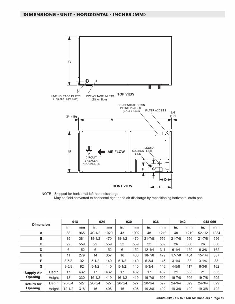
Dimension018 024 030 036 042 048-060
in. mm in. mm in. mm in. mm in. mm in. mmA 38 965 40-1/2 1029 43 1092 48 1219 48 1219 52-1/2 1334B 15 381 18-1/2 470 18-1/2 470 21-7/8 556 21-7/8 556 21-7/8 556C 22 559 22 559 22 559 22 559 26 660 26 660D 6 152 6 152 6 152 12-1/4 311 6-1/4 159 6-3/8 162E 11 279 14 357 16 406 18-7/8 479 17-7/8 454 15-1/4 387F 3-5/8 92 5-1/2 140 5-1/2 140 5-3/4 146 3-1/4 83 3-1/4 83G 3-5/8 92 5-1/2 140 5-1/2 140 5-3/4 146 4-5/8 117 6-3/8 162
Supply Air Opening
Depth 17 432 17 432 17 432 17 432 21 533 21 533Height 13 330 16-1/2 419 16-1/2 419 19-7/8 505 19-7/8 505 19-7/8 505
Return Air Opening
Depth 20-3/4 527 20-3/4 527 20-3/4 527 20-3/4 527 24-3/4 629 24-3/4 629Height 12-1/2 318 16 406 16 406 19-3/8 492 19-3/8 492 19-3/8 492
DIMENSIONS - UNIT - HORIZONTAL - INCHES (MM)
A
C
B
D
E
F
FRONT VIEW
TOP VIEWLINE VOLTAGE INLETS(Top and Right Side)
LOW VOLTAGE INLETS(Either Side)
SUCTIONLINE
LIQUIDLINE
FILTER ACCESS
CONDENSATE DRAINPIPING PLATE (4)
(2-1/4 x 3-3/4)
3/4 (19)
AIR FLOW
3/4(19)
G
CIRCUITBREAKER
KNOCKOUTS
NOTE - Shipped for horizontal left-hand discharge. May be field converted to horizontal right-hand air discharge by repositioning horizontal drain pan.

CBX25UHV - 1.5 to 5 ton Air Handlers / Page 20
DIMENSIONS - ACCESSORIES - INCHES (MM)
ADJUSTABLE20 (508) to
25 (635)ALL UNITS
16(406)
6(152)
SIDE RETURN UNIT STAND(Upflow Only)
21-1/4(540)
INSTALLATION CLEARANCES WITH ELECTRIC HEATCabinet 0 inch (0 mm)To Plenum 0 inch (0 mm)To Outlet Duct within 3 feet (914 mm) 0 inch (0 mm)Floor 0 inch (0 mm)Service / Maintenance See Note #11 Front service access - 24 inches (610 mm) minimum.NOTE - If cabinet depth is more than 24 inches (610 mm), allow a minimum of the cabinet depth plus 2 inches (51 mm).


NOTE - Due to Lennox’ ongoing commitment to quality, Specifications, Ratings and Dimensions subject to change without notice and without incurring liability. Improper installation, adjustment, alteration, service or maintenance can cause property damage or personal injury. Installation and service must be performed by a qualified installer and servicing agency. ©2015 Lennox Industries, Inc.
Visit us at www.lennox.com For the latest technical information, www.lennoxdavenet.com Contact us at 1-800-4-LENNOX
REVISIONS
Sections Description of Change
Electric Heat Data New catalog numbers for most electric heat models.
REVISIONS
Related Documents