Copyright © Nokia Corporation 2002-2004. All rights reserved. Version 4.0 NOKIA GSM CONNECTIVITY TERMINAL PRODUCT GUIDE

Welcome message from author
This document is posted to help you gain knowledge. Please leave a comment to let me know what you think about it! Share it to your friends and learn new things together.
Transcript
Cop
yrig
ht ©
Nok
ia C
orpo
ratio
n 20
02-2
004.
All
right
s re
serv
ed. V
ersi
on 4
.0
NOKIA GSM CONNECTIVITY TERMINAL PRODUCT GUIDE
Contents ACRONYMS AND TERMS ......................................................................................................2 1. REFERENCES.................................................................................................................3 2. DOCUMENT SCOPE .......................................................................................................4 3. PRODUCT CONCEPT AND USAGE...............................................................................5 4. OPERATING MODES ......................................................................................................6
4.1 USER CONTROL MODE...........................................................................................6 4.2 AT COMMAND MODE...............................................................................................7 4.3 M2M SYSTEM MODE ...............................................................................................8
5. FEATURES ....................................................................................................................10 5.1 WIRELESS DATA BEARERS..................................................................................10 5.2 RELIABILITY AND ACCESS CONTROL.................................................................11 5.3 SUPPLEMENTARY SERVICES ..............................................................................12
6. USER INTERFACE ........................................................................................................13 7. INTERFACES.................................................................................................................15
7.1 M2M SYSTEM CONNECTOR .................................................................................16 7.1.1 REMOTE I/O CONTROL......................................................................................16 7.1.2 DIGITAL AND ANALOG AUDIO ..........................................................................17 7.1.3 POWERING .........................................................................................................17
7.2 POWER CONNECTOR ...........................................................................................17 7.3 SIM CARD READER ...............................................................................................17 7.4 ANTENNA INTERFACE ..........................................................................................18
8. SALES PACKAGES .......................................................................................................19 8.1 COMPLETE SALES PACKAGE ..............................................................................19 8.2 BASIC SALES PACKAGE .......................................................................................20
9. ACCESSORIES .............................................................................................................22 9.1 POWER SUPPLY ....................................................................................................22 9.2 VEHICLE POWER SUPPLY KIT .............................................................................22 9.3 DATA PACKAGE .....................................................................................................22 9.4 NOKIA SMART ADAPTER ......................................................................................24 9.5 EXTERNAL ANTENNA CABLE ...............................................................................24 9.6 CONFIGURATOR SOFTWARE ..............................................................................25
10. APPLICATION DEVELOPMENT....................................................................................26
11. CORBA AND NOKIA GSM CONNECTIVITY TERMINAL..............................................27 11.1 THE NOKIA GSM CONNECTIVITY TERMINAL INTERFACES..............................27
12. PRODUCT SPECIFICATION .........................................................................................29 APPENDIX 1: DOCUMENT LIST FOR NOKIA GSM CONNECTIVITY TERMINALS............34
OVERVIEW DOCUMENTS................................................................................................34 DOCUMENTS AND SOFTWARE FOR USER CONTROL MODE ....................................34 DOCUMENTS AND SOFTWARE FOR AT COMMAND MODE ........................................35 DOCUMENTS AND SOFTWARE FOR M2M SYSTEM MODE .........................................36

Legal Notice
Copyright © 2002 - 2004 Nokia. All rights reserved.
Reproduction, transfer, distribution, or storage of part or all of the contents in this document in any form without the prior written permission of Nokia is prohibited.
Nokia and Nokia Connecting People are registered trademarks of Nokia Corporation. Java and all Java-based marks are trademarks or registered trademarks of Sun Microsystems, Inc. Other product and company names mentioned herein may be trademarks or trade names of their respective owners.
Nokia operates a policy of continuous development. Nokia reserves the right to make changes and improvements to any of the products described in this document without prior notice.
Under no circumstances shall Nokia be responsible for any loss of data or income or any special, incidental, consequential or indirect damages howsoever caused.
The contents of this document are provided "as is". Except as required by applicable law, no warranties of any kind, either express or implied, including, but not limited to, the implied warranties of merchantability and fitness for a particular purpose, are made in relation to the accuracy, reliability, or contents of this document. Nokia reserves the right to revise this document or withdraw it at any time without prior notice.

ACRONYMS AND TERMS
Acronym/Term Description
API Application Programming Interface
AT Attention
CORBA Common Object Request Broker Architecture
CSD Circuit Switched Data
DAI Digital audio interface
GIOP General Inter-ORB Protocol, General Inter-Object Request Broker Protocol
GSM Group Special Mobile, Global System for Mobile Communications
GPRS General Packet Radio Service
HSCSD High Speed Circuit Switched Data
IDL Interface Definition Language
M2M Machine-to-Machine, Mobile-to-Machine, Machine-to-Mobile
MO Mobile Originated
MT Mobile Terminated
ORB Object Request Broker
PC Personal Computer
PIN Personal Identity Number
PUK Personal Unblocking Key
SIM Subscriber Identity Module
SM Short Message
SMS Short Message Service
SMSC Short Message Service Centre
USSD Unstructured Supplementary Services Data
Copyright © Nokia 2002 – 2004. All rights reserved.
2/37

1. REFERENCES
Please visit http://www.forum.nokia.com/m2m or http://www.americas.forum.nokia.com for referenced documents.
1. Guide for User Control Mode for Nokia GSM Connectivity Terminal 2. M2M System Connector Electrical Specification for Nokia GSM
Connectivity Terminals 3. Nokia GSM Connectivity Terminal Technical Specification 4. Nokia Smart Adapter Product Guide 5. Nokia GSM Connectivity Terminal AT Command Guide
Please see Appendix 1: Document list for Nokia GSM Connectivity Terminals for more complete list of technical documentation and supporting software for the Nokia GSM Connectivity Terminals.
Copyright © Nokia 2002 – 2004. All rights reserved.
3/37
2. DOCUMENT SCOPE
This document describes the main characteristics of the Nokia 30 GSM Connectivity Terminal and Nokia 31 GSM Connectivity Terminal (in the document referred to as the “Nokia GSM Connectivity Terminal” or simply as the “terminal”). Sales packages and accessories are also described in this document.
For more detailed information and information about application development and development support for M2M, please visit our website at http://www.forum.nokia.com/m2m or http://www.americas.forum.nokia.com.
Copyright © Nokia 2002 – 2004. All rights reserved.
4/37

3. PRODUCT CONCEPT AND USAGE
As we move quickly towards the third generation mobile world, more attention than ever is being paid to the wireless data market. We have only seen the first steps that have been taken towards the future of the mobile information society, but it is already clear that wireless data will be about a lot more than just web browsing. Machine-to-machine (M2M) communication solutions are an important part of wireless data services, making valuable information and services available to corporations and mobile users alike. The market potential is huge, and new applications are emerging continuously when operators, service providers and developers are searching opportunities for growth. The telecom industry in general is shifting towards end-to-end solutions, which requires reliable communication and information transfer.
M2M communications give corporations the opportunity to make savings in operational costs, enhance their customer service, and so on. Examples of M2M applications are the remote control of utility meters or vending machines, traffic information, industrial applications, security and surveillance, sales and payments, fleet management, telemedicine, public services and much more.
The Nokia GSM Connectivity Terminal is an M2M (machine-to-machine) communications device with versatile interfaces and advanced functions. Connected to different machines and devices, it provides wireless connectivity and remote management possibilities for customer applications through its three operation modes. It offers GPRS, USSD, high-speed data, as well as other advanced services, over EGSM900/GSM1800 (Nokia 30 terminal) and GSM850/1900 (Nokia 31 terminal) networks. It is a perfect fit for various application environments for its size, versatility and reliability.
Note: The Nokia 31 terminal supports data call bit rates from 2,400 to 14,400 bps.
Copyright © Nokia 2002 – 2004. All rights reserved.
5/37
4. OPERATING MODES
Each M2M application has different needs for wireless connectivity. M2M applications range from controlling door locks to tracking cargo. For this reason the Nokia GSM Connectivity Terminal supports three operation modes to choose from. Selection is based on the nature of the application and the needs of the application.
The User control mode is especially designed with mobile-to-machine and machine-to-mobile communications in mind. One can easily control simple applications built using the services of the Nokia GSM Connectivity Terminal with a mobile handset.
The AT command mode offers efficient point-to-point communications through the modem capabilities of the Nokia GSM Connectivity Terminal.
The M2M System mode in turn takes in full use all the advanced services offered by the Nokia GSM Connectivity Terminal. In the M2M System mode, the Nokia GSM Connectivity Terminal functions as a part of the intelligent Nokia M2M Platform that offers seamless wireless communications for different machine-to-machine solutions.
4.1 USER CONTROL MODE An example of a device attached to the Nokia GSM Connectivity Terminal for wireless control would be a refrigerator. One might want to check the temperature of the refrigerator when out of town. One could also want to check if the door of the refrigerator was left open. It would even be possible to lock the refrigerator door from afar. This could be done with a text message sent from a mobile handset.
Functionality as described above could be achieved with a Nokia GSM Connectivity terminal physically attached to the refrigerator. The Nokia GSM Connectivity terminal incorporates a built-in service, the User Control Mode, for device control and monitoring wirelessly, with a mobile handset. A text message is sent from the mobile handset to the terminal, which in turn controls the device attached to it. For example the temperature of a refrigerator can be checked with text message sent from a mobile handset.
A refrigerator is just one example of a device or machine that can be controlled wirelessly using the User Control Mode. Also other devices ranging from electrical locks to lamps can be put on or off. Thus, a device that simply needs to be put on or off can be controlled using User Control Mode. As for monitoring devices or machines, the same applies. It can be checked wirelessly, if something is on or off. E.g. it can be checked if a door is open or closed. Also a device value can be checked, e.g. what is the temperature reading of a thermometer. If the device or machine in turn has a need e.g. to make a voice
Copyright © Nokia 2002 – 2004. All rights reserved.
6/37

call, other modes of operation offered by the Nokia GSM Connectivity terminal should be used for that.
It is possible to connect five devices to one Nokia GSM Connectivity terminal for wireless remote control, and three devices for wireless remote monitoring. For more information about the connection interface for User Control Mode, please see Chapter 7.1.1.
In Table 1 the services offered by the User Control Mode are listed. For a detailed technical description of the functionalities, please see Guide for User Control Mode for Nokia GSM Connectivity Terminal.
Table 1 Functions offered by User Control Mode.
Function Details
Control a device Switch devices on or off
Switch devices on or off for a period of time
Monitor a device Find out if a device is already on or off
Receive alarm calls if a device has been switched on or off
Receive alarm calls if a threshold has been crossed
Personalize Define your own device commands (aliases)
Disable acknowledgements for device commands
Select the frequency of alarm calls (alarm once / continuously)
Identify the calling party and give permissions for device control
4.2 AT COMMAND MODE Besides the User Control Mode, the Nokia GSM Connectivity Terminal can also be used as a wireless modem in AT Command mode. The AT command mode offers efficient point-to-point communications through the modem capabilities of the Nokia GSM Connectivity Terminal. As a wireless modem, the terminal can be used for data and fax communication when attached to a compatible PC or a compatible device. In addition to this, the terminal can be controlled directly with AT commands by different machines and devices, for example.
Wireless modem usage is enabled with an RS-232 data adapter connected to the Nokia GSM Connectivity Terminal; see Figure 7. The RS-232 adapter has a connector for the standard RS-232 data cable. The RS-232 data cable is then connected to a compatible PC or another compatible device. In addition to this, AT commands are also available via the M2M System Connector.
All applicable ITU-T V.25ter, ETSI GSM 07.07 and ETSI 07.05 AT commands are supported. The supported AT commands are described in the AT Command Guide document, which is available on the Nokia 30 and Nokia 31
Copyright © Nokia 2002 – 2004. All rights reserved.
7/37
CD-ROM included in the complete sales package (see chapter 8.1) and in the RS-232 data package (see chapter 9.3).
In modem use, no Nokia-specific user interface software or driver is required. The Nokia GSM Connectivity Terminal can be used with standard modem drivers and communications applications. However, also a special modem driver for the terminal is provided in the Nokia 30 and Nokia 31CD-ROM included in the complete sales package (see chapter 8.1) and in the RS-232 data package (see chapter 9.3).
The Nokia 30 and Nokia 31 complete sales package includes all of the accessories required for the terminal to be used as a wireless data modem. Alternatively, GSM modem functionality can be achieved with the Nokia 30 and Nokia 31 basic sales package combined with the data package and a power supply unit. (See chapters 8 and 8.2)
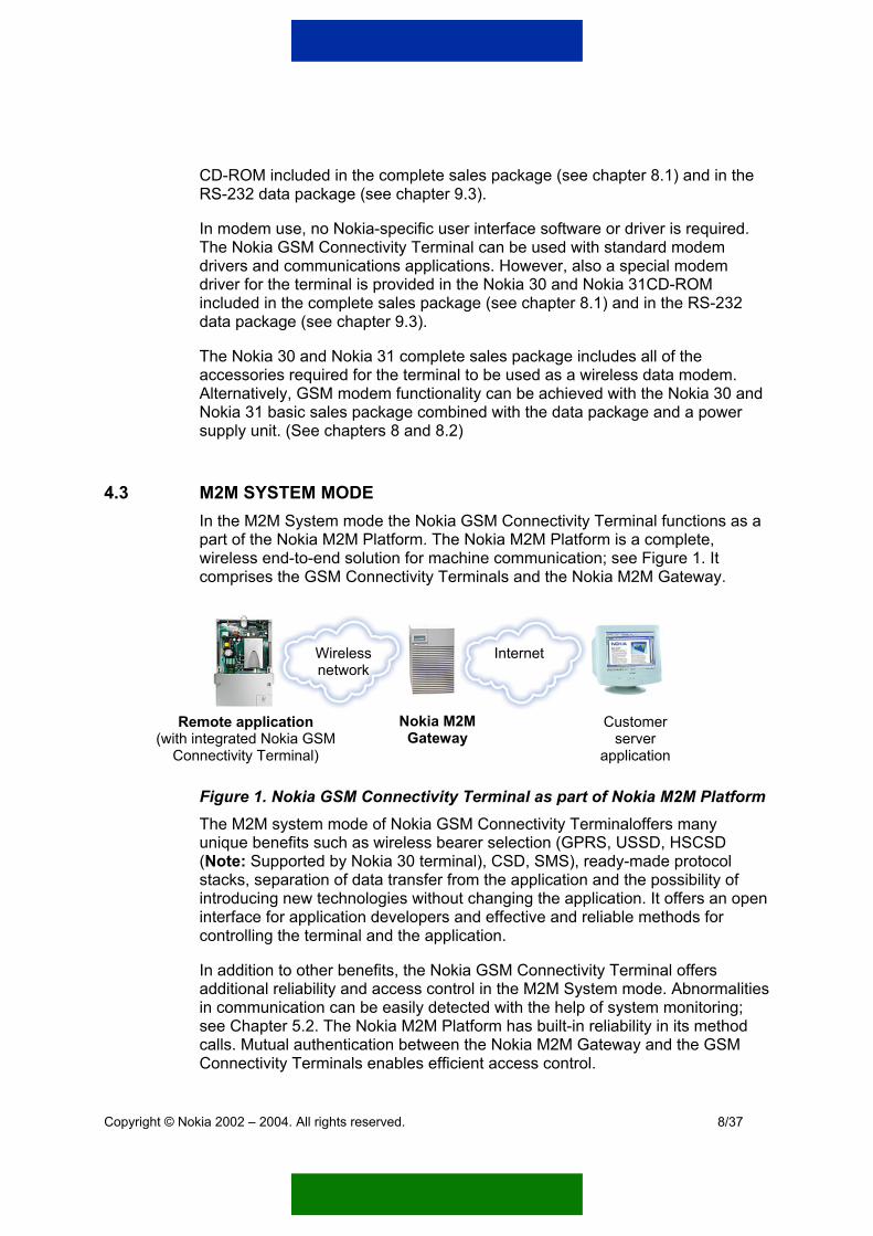
4.3 M2M SYSTEM MODE In the M2M System mode the Nokia GSM Connectivity Terminal functions as a part of the Nokia M2M Platform. The Nokia M2M Platform is a complete, wireless end-to-end solution for machine communication; see Figure 1. It comprises the GSM Connectivity Terminals and the Nokia M2M Gateway.
Wireless network
Internet
Remote applica(with integrated Nok
Connectivity Term
Figure 1. NoThe M2M syunique bene(Note: Suppstacks, sepaintroducing ninterface for controlling th
In addition toadditional rein communicsee Chaptercalls. MutuaConnectivity
Copyright © Nokia 2002 – 2004
Nokia M2M Gateway
tion ia GSM inal)
kia GSM Connectivity Terminal as parstem mode of Nokia GSM Connectivity Tefits such as wireless bearer selection (GPorted by Nokia 30 terminal), CSD, SMS), ration of data transfer from the applicationew technologies without changing the apapplication developers and effective and e terminal and the application.
other benefits, the Nokia GSM Connectiliability and access control in the M2M Syation can be easily detected with the help 5.2. The Nokia M2M Platform has built-inl authentication between the Nokia M2M G Terminals enables efficient access contro
. All rights reserved.
Customer server
application
t of Nokia M2M Platform rminaloffers many RS, USSD, HSCSD ready-made protocol and the possibility of
plication. It offers an open reliable methods for
vity Terminal offers stem mode. Abnormalities of system monitoring; reliability in its method ateway and the GSM l.
8/37
Technologically, the Nokia M2M Platform is an object-oriented SW platform based on CORBA, an open and widely accepted industry standard. The Nokia M2M Platform is adaptable to a wide range of purposes and communication methods and can be used in several applications. The Nokia M2M Platform hides network complexities and is transparent to different machines, OS and language implementation, thanks to CORBA method calls. (See Chapter 10).
In the M2M System mode, the services offered by the Nokia GSM Connectivity Terminal are used via its M2M system connector (Figure 3) or RS-232 interface available with RS-232 Data Adapter (see Figure 7). In the former case the application module is connected directly, or using flat cable, to the Nokia GSM Connectivity Terminal via the M2M system connector. In the latter case a standard RS-232 cable can be used.
Copyright © Nokia 2002 – 2004. All rights reserved.
9/37

5. FEATURES
5.1 WIRELESS DATA BEARERS The Nokia GSM Connectivity Terminal supports five bearers for wireless data transfer, which can be used where GSM networks support them.
- General Packet Radio Service (GPRS)
- High speed circuit switched data (HSCSD) (Note: Supported only by Nokia 30 GSM Terminal)
- Circuit switched data (CSD)
- Short messages (SMS)
- Unstructured Supplementary Service Data (USSD)
General Packet Radio Service (GPRS) utilises packet switched technology where information is transmitted in small bursts of data. The GPRS mobile station class is class B. This means that both GPRS connections and circuit switched connections are possible, although it has to be defined which one is used each time. The Nokia GSM Connectivity Terminal supports GPRS multi-slot class 6, thus multiple timeslots can be used for data transfer at the same time: 3 + 1, 2 + 2, 2 + 1 or 1+1 slots.
With High Speed Circuit Switched Data (HSCSD), the Nokia 30 is a multi-slot class 6 terminal and offers data transfer speeds of up to 43.2kbit/s when 3+1 timeslots are in use.
Circuit switched data offers data speeds of up to 14.4kbit/s.
The Short Message Service allows the user to send and receive messages of up to 160 characters via the Nokia GSM Connectivity Terminal. The service can deliver messages to the terminal whenever it is connected to the network, even when the terminal is engaged on an active call. SMS is a convenient way of passing data quickly and easily to and from Nokia GSM Connectivity Terminals. The Nokia GSM Connectivity Terminal supports also binary format SMS.
Note: The Nokia GSM Connectivity Terminal supports Unicode SMS messages for graphical character sending in AT command mode. In this case binary format messages should be used and the encoding and decoding of messages should be provided externally. Please see Nokia GSM Connectivity Terminal Technical Specification for more detailed information.
Copyright © Nokia 2002 – 2004. All rights reserved.
10/37
Unstructured Supplementary Services Data (USSD) offers reliable interactive messaging services. USSD allows the user to send and receive messages of up to 182 characters via the Nokia Connectivity Terminal. When USSD is used, a session is established for the duration of the connection. This increases data transfer reliability, as the delay is known. In addition, it shortens response times.
With the Nokia Connectivity Terminal, it is possible to choose which bearer is used in the application. With a wireless bearer choice, communication costs can be optimized. When new technologies and bearers are introduced, the onward compatibility of the Nokia Connectivity Terminal offers the possibility of choosing from more bearers.
5.2 RELIABILITY AND ACCESS CONTROL The Nokia Connectivity Terminal supports normal GSM encryption, GSM security codes, AutoPIN, system monitoring and authentication to ensure the reliability and security of the M2M application.
The Nokia Connectivity Terminal, as part of the Nokia M2M Platform, offers reliability through a supervised data pipeline. Supervision is provided by effective and reliable methods for controlling the terminals and the application via CORBA method calls. Connection between the Gateway and the Nokia Connectivity Terminal is mutually authenticated to prevent any intervention. Additional methods for security and encryption can be completed by the application.
With the Nokia Connectivity Terminal’s reliability features and supervision provided by the Nokia M2M Platform, full control of a customer’s M2M application is possible. Messages are passed to the correct destination, in the correct form, in a way that can also be tracked.
GSM encryption
The Nokia Connectivity Terminal supports normal GSM encryption for end-user privacy.
GSM security codes
The Nokia Connectivity Terminal supports the following GSM security codes:
- PIN / PIN 2
- PUK / PUK 2
- SECURITYCODE
- CALLBARRINGCODE
Copyright © Nokia 2002 – 2004. All rights reserved.
11/37

Security codes can be changed via the Nokia Connectivity Terminal Configurator (see Chapter 9.6) as well as from the network and from the application module.
AutoPIN
SIM security enables device recovery following (occasional) power cuts without on-site intervention and helps prevent fraud. SIM security is achieved using the AutoPIN feature. The PIN code is programmed in the terminal’s memory where it is relayed in unusual situations. When AutoPIN is in use, the SIM card is useless to any outsider.
System monitoring
Connection between the Nokia Connectivity Terminal and the application module is checked periodically by live checks. Based on the live checks, the Nokia Connectivity Terminal and the application module can be reset automatically if the connection between them breaks. This feature only exists in the M2M system mode (see Chapter 4.3) when traffic is sent through the M2M system connector.
Authentication
The terminal and Gateway authenticate each other when circuit switched data or high speed circuit switched data is used. This kind of authentication can be used in the M2M System mode.
5.3 SUPPLEMENTARY SERVICES Supplementary service features are network services. They are special services provided by wireless network service providers and therefore vary from one network and country to another.
The Nokia Connectivity Terminal supports the following GSM phase 2+ supplementary services.
- Call Forwarding
- Call Waiting
- In-Call Handling
- Call Restriction
- Security Options
- Call Transfer
- Multiparty Call
Copyright © Nokia 2002 – 2004. All rights reserved.
12/37

6. USER INTERFACE
Three light indicators (LEDs, light emitting diodes) form the user interface of the Nokia Connectivity Terminal. The LED user interface is shown in Figure 2 and Figure 4. LED 1 shows the terminal status, while the other two are reserved for the application module following start-up. During start-up and special operations, all three light indicators are in terminal use. The functionality of the light indicators in start-up, normal, and special situations, is described in Table 2, Table 3, and Table 4, respectively. All three LEDs can also be configured so that they will not show any status and will stay off during any operation.
Figure 2 Nokia Connectivity Terminal light indicators and their numbering.
Table 2. Nokia Connectivity Terminal light indicator states during start-up.
LED 1 LED 2 Status LED 3 Description
- - - Power off / silent mode
Green scan Green scan Green scan Power on, connecting to network
- Red blink - PIN query
Green/Red blink Green/Red blink Green/Red blink PUK query
Intensity of Field Strength:
Red blink - - <-105 dBm
Green Blink - - Non-acceptable
-105 … -100 dBm
Green - - -100 … -95 dBm
Green Green Blink - Weak
-95 … -90 dBm
Green Green - -90 … -85 dBm
Green Green Green Blink Moderate
-85 … -80 dBm
Green Green Green Good >-80 dBm
Copyright © Nokia 2002 – 2004. All rights reserved.
13/37
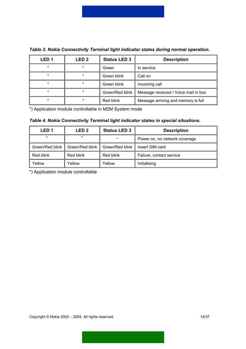
Table 3. Nokia Connectivity Terminal light indicator states during normal operation.
LED 1 LED 2 Status LED 3 Description
* * Green In service
* * Green blink Call on
* * Green blink Incoming call
* * Green/Red blink Message received / Voice mail in box
* * Red blink Message arriving and memory is full
*) Application module controllable in M2M System mode
Table 4. Nokia Connectivity Terminal light indicator states in special situations.
LED 1 LED 2 Status LED 3 Description * * - Power on, no network coverage
Green/Red blink Green/Red blink Green/Red blink Insert SIM card
Red blink Red blink Red blink Failure, contact service
Yellow Yellow Yellow Initialising
*) Application module controllable
Copyright © Nokia 2002 – 2004. All rights reserved.
14/37

7. INTERFACES
Nokia GSM Connectivity Terminal main interfaces are shown in Figure 3 and Figure 4.
M2M system connector
Power interface
Figure 3 Nokia GSM Connectivity Terminal, bot
Led user interface
SIM cover
Ss
Figure 4 Nokia GSM Connectivity Terminal, to
Copyright © Nokia 2002 – 2004. All rights reserved.
tom view
External antenna connector
IM card lot
p view
15/37
7.1 M2M SYSTEM CONNECTOR The M2M system connector offers an open interface for application developers. The primary physical interface to the application module is through the 50-pin M2M System Connector. The M2M System Connector is shown Figure 3.
The M2M System Connector offers the following functionalities for the application module:
• Remote I/O control (see chapter 7.1.1)
o 5 digital general-purpose outputs
o 3 analog or digital general-purpose inputs
• Two serial ports for data communication
o M2M System port
o RS-232 port
• Interfaces for either digital or analog audio (see chapter 7.1.2)
• Powering (see chapters 7.1.3 and 7.2)
o Power supply for application
o Power supply for terminal
• Reset signal for application module
For more information on serial ports for data communication and reset signal for application module, see Nokia GSM Connectivity Terminal Technical Specification.
For more information about the M2M System Connector, please see Nokia GSM Connectivity Terminal Technical Specification. For electrical characteristics of the M2M System Connector, please see M2M System Connector Electrical Specification for Nokia GSM Connectivity Terminal.
7.1.1 Remote I/O control There are three general-purpose inputs and five general-purpose outputs on the M2M system connector. The inputs can be used in either digital (on/off) or analog (continuous signal) mode. The outputs can be used in digital mode only (set something on/off).
Copyright © Nokia 2002 – 2004. All rights reserved.
16/37
The general-purpose inputs and outputs can be controlled with either specific text messages in the User control mode (see Chapter 4.1) or with CORBA method calls in the M2M System Mode (see Chapter 4.3).
Note: The availability of the inputs and outputs changes depending on the selected mode. Those are described in the Ref. 2.
7.1.2 Digital and analog audio The Nokia GSM Terminal offers digital audio functionality for GSM via Digital Audio Interface (DAI). DAI support is found in the M2M system connector. An external audio codec is required.
The M2M system connector also supports analog audio functionality that is an alternative to the Digital Audio Interface. Microphones and headphones can be connected through the analog audio signal interface.
7.1.3 Powering The M2M system connector provides regulated voltage for the application. Alternatively, the application module can supply the terminal with a wide voltage range.
- DC input voltage range: 4.75 V – 15.0 V
The Nokia GSM Connectivity Terminal has a regulated switch able power output for customer application.
- DC output voltage: 3.6 V DC
- DC output current: 300 mA
The Nokia GSM Connectivity Terminal also has a connector for ACW-5A power supply. See chapter 7.2.
7.2 POWER CONNECTOR The Nokia GSM Connectivity Terminal has a DC connector for the Nokia ACW-5A power supply. The power interface is shown in Figure 3.
o Input voltage range: 6.2 Vdc – 14.0 Vdc
7.3 SIM CARD READER The Nokia GSM Connectivity Terminal supports small-sized 3 V SIM cards. The SIM card slot is shown in Figure 4.
Copyright © Nokia 2002 – 2004. All rights reserved.
17/37

7.4 ANTENNA INTERFACE The Nokia GSM Connectivity Terminal incorporates an internal dual-band antenna. The transmitting (RF) power of the Nokia 30 is 2W (max) in GSM900 and 1W (max) in GSM1800 networks and for Nokia 31 is 2W (max) in GSM 850 and 1W (max) in GSM 1900 networks.
Also an external antenna interface is available. The external antenna interface is shown in Figure 4. An external antenna cable is available as an accessory for the Nokia 30 and Nokia 31 terminal, please see Chapter 9.4.
Copyright © Nokia 2002 – 2004. All rights reserved.
18/37

8. SALES PACKAGES
The Nokia GSM Connectivity Terminal is available in two sales packages: a basic sales package and a complete sales package.
8.1 COMPLETE SALES PACKAGE 1. Nokia GSM Connectivity Terminal (Nokia 30 terminal or Nokia 31 terminal)
2. Power supply ACW-5A
3. Data adapter RS-232
4. Data cable RS-232
5. Installation kit
6. Product note
7. Nokia GSM Connectivity Terminal CD-ROM includes: User’s guide for modem use, AT command list, Modem options for Nokia GSM Connectivity Terminal, Nokia GSM Connectivity Terminal Configurator
Sales package contents are shown in Figure 5.
Copyright © Nokia 2002 – 2004. All rights reserved.
19/37
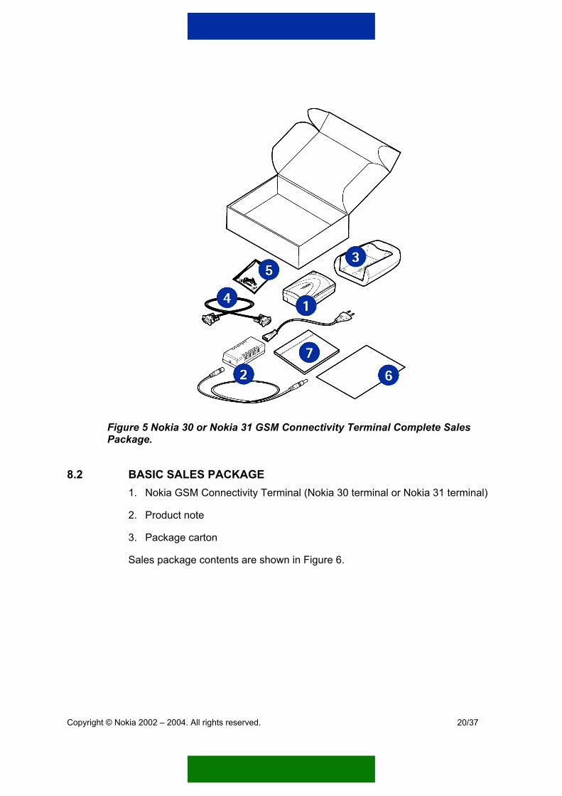
Figure 5 Nokia 30 or Nokia 31 GSM Connectivity Terminal Complete Sales Package.
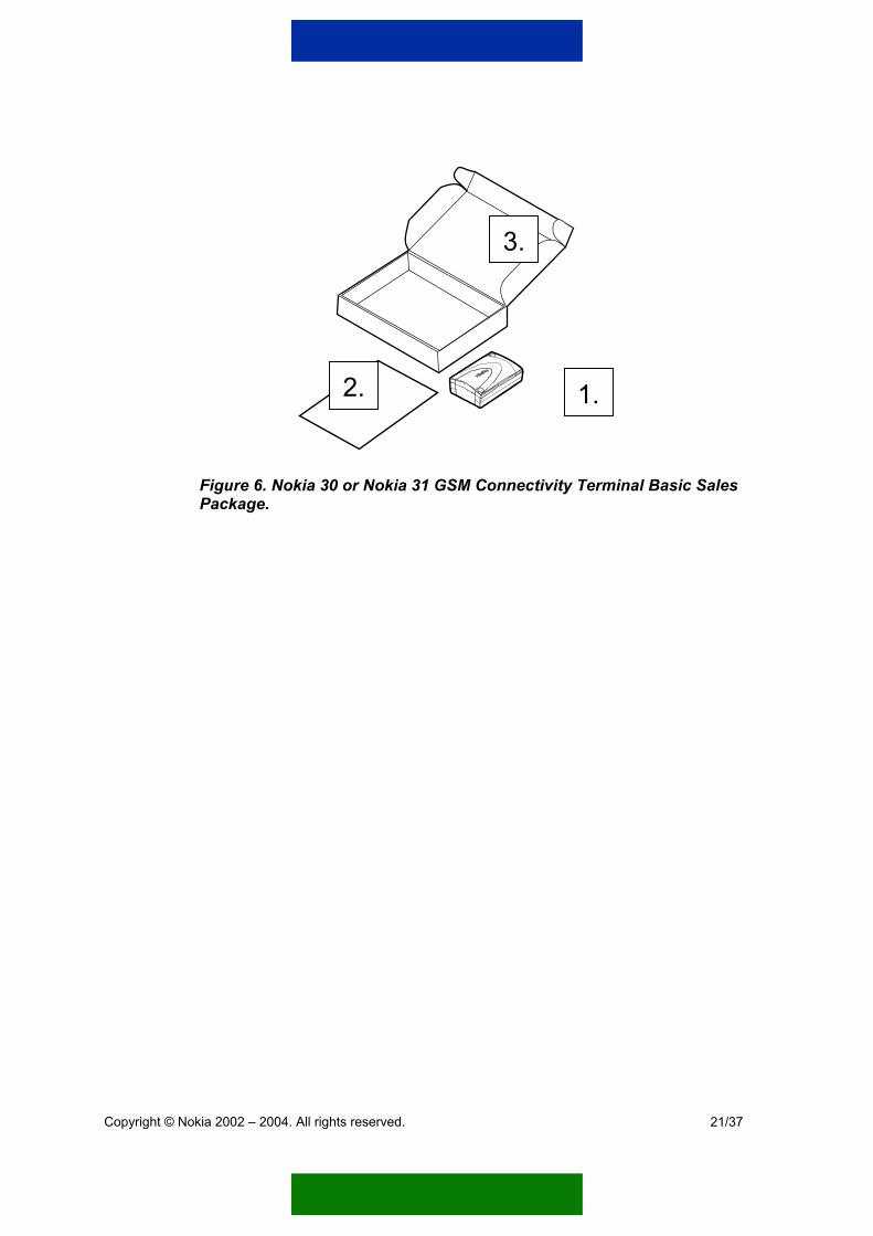
8.2 BASIC SALES PACKAGE 1. Nokia GSM Connectivity Terminal (Nokia 30 terminal or Nokia 31 terminal)
2. Product note
3. Package carton
Sales package contents are shown in Figure 6.
Copyright © Nokia 2002 – 2004. All rights reserved.
20/37
3.
2. 1.
Figure 6. Nokia 30 or Nokia 31 GSM Connectivity Terminal Basic Sales Package.
Copyright © Nokia 2002 – 2004. All rights reserved.
21/37
9. ACCESSORIES
A full range of accessories is available for the Nokia GSM Connectivity Terminal.
o Power supply ACW-5A
o Vehicle power supply kit LCM-2
o RS-232 Data package
o Nokia Smart Adapter
o Antenna adapter
o Configurator software
9.1 POWER SUPPLY A power supply unit (ACW-5A) is included in the complete sales packages and the Power supply accessory sales packages. The power supply plug type (Euro, UK, US, Australian) depends on the country and region.
9.2 VEHICLE POWER SUPPLY KIT With the Vehicle power supply kit (LCM-2) it is possible to power up the Nokia GSM Connectivity Terminal from a vehicle battery. Connections of 12 V or 24 V are supported. The Vehicle power supply kit is available as an accessory including power supply, input power cable for vehicle battery connection and output power cable for connection to the Nokia GSM Connectivity Terminal. An installation note is included in the sales package as well.
9.3 DATA PACKAGE The data package includes:
o Data adapter RS-232
o Data cable RS-232
o Nokia GSM Connectivity Terminal CD-ROM: user’s guide for modem use, AT command list, Modem options for Nokia GSM Connectivity Terminal, Nokia GSM Connectivity Terminal Configurator
Data cable RS-232 and data adapter RS-232 are required when the Nokia GSM Connectivity Terminal is used in AT command mode as a data modem.
Copyright © Nokia 2002 – 2004. All rights reserved.
22/37

The data cable RS-232 is connected to the D9 connector in the RS-232 adapter and to the serial port of an application module, a computer, or other compatible device.
Figure 7 Mounting the Nokia GSM Connectivity Terminal to the Data adapter RS-232.
Figure 8 Data cable RS-232.
Copyright © Nokia 2002 – 2004. All rights reserved.
23/37
9.4 NOKIA SMART ADAPTER Nokia Smart Adapter is a device for connecting the Nokia GSM Connectivity Terminal to a compatible remote device through a serial interface (DB9) (see Figure 7).
For the remote device, Smart Adapter offers the standard RS-232 serial interface, whose functionality can be defined by writing device driver software. This software component determines the protocol the Smart Adapter will use to communicate with the controlled device, as well as the other application intelligence required.
The Nokia Smart Adapter is available as a separate accessory.
For more information about the Nokia Smart Adapter, please see Nokia Smart Adapter Product Guide.
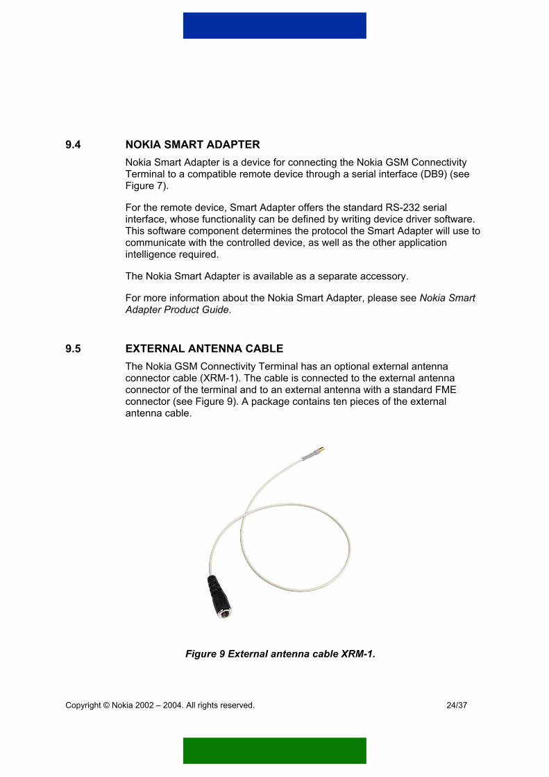
9.5 EXTERNAL ANTENNA CABLE The Nokia GSM Connectivity Terminal has an optional external antenna connector cable (XRM-1). The cable is connected to the external antenna connector of the terminal and to an external antenna with a standard FME connector (see Figure 9). A package contains ten pieces of the external antenna cable.
Figure 9 External antenna cable XRM-1.
Copyright © Nokia 2002 – 2004. All rights reserved.
24/37
9.6 CONFIGURATOR SOFTWARE Configurator software is used when the Nokia GSM Connectivity Terminal is activated for the first time, or when terminal settings need to be changed. It helps to modify the basic settings of the terminal so that the connection to the Gateway can be established. For example the following configurations can be configured with the software:
o User Control Mode settings
o M2M System settings
o Remote I/O control settings
o GSM security settings
o GSM settings
o Quick install
A PC or laptop, data adapter RS-232 and data cable RS-232 are required when configuring the Nokia GSM Connectivity Terminal. Nokia GSM Connectivity Terminal Configurator software is included in the Nokia 30 or Nokia 31 CD-ROM provided in the Complete sales package and in the Data package. It is also available from the Forum Nokia web page: http://www.forum.nokia.com/m2m or http://www.americas.forum.nokia.com
Copyright © Nokia 2002 – 2004. All rights reserved.
25/37
10. APPLICATION DEVELOPMENT
In a typical M2M system the Nokia GSM Connectivity Terminal is integrated to a remote asset (device) that is monitored and controlled from a server application. In simple systems, a person can control the remote asset via normal GSM phone instead of using a server application.
Nokia GSM Connectivity Terminal can be integrated to the remote asset via input and output pins provided in the M2M system connector. The pins can be set and read by a server application via in-build software interfaces of the Nokia GSM Connectivity Terminal. Also, a person can access the signal states with text messages.
There may be a need to process information more complex than just simple input and output pin data. The device may produce data that must be first processed with a certain algorithm. According the results, there may be a need to distribute information to the server application.
Nokia GSM Connectivity Terminal provides certain software interfaces and AT commands for communicating with the server software. The intelligence (remote application) resides in the remote asset that may include a logical element such as a micro controller. The micro controller is connected to the Nokia GSM Connectivity Terminal via a serial interface. The intelligence can be also close to the remote asset in a separate “bridge” element such as Nokia Smart Adapter.
With AT commands, the Nokia GSM Connectivity Terminal works as any GSM modem. Please refer to Nokia GSM Connectivity Terminal AT Command Guide for further information about the available AT commands.
In-build software interfaces can by utilized for effective communication with the server software and for accessing the services provided by the Nokia GSM Connectivity Terminal. To utilize these CORBA software interfaces, some software libraries, provided by Nokia, need to be integrated to the remote application.
Copyright © Nokia 2002 – 2004. All rights reserved.
26/37
11. CORBA AND NOKIA GSM CONNECTIVITY TERMINAL
The CORBA (Common Object Request Broker Architecture) is a widely distributed computing infrastructure, standardized by the Object Management Group (OMG) consortium. In short, CORBA applications are composed of objects which can be located within different machines. Objects have services and they are utilized with request messages. The CORBA hides the underlying transferring network, such as the Internet or GSM network as well as the underlying protocols, so that a user can use functions as local procedure calls.
Object services are described with an abstract language named IDL (Interface Definition Language). The IDL also provides the necessary information required to develop clients that use an object's interface operations. The interface definition specifies which member functions, data types, attributes and exceptions are available to a client, without making any assumptions about an object’s implementation. An IDL compiler is responsible for mapping IDL interfaces onto the particular programming language, such as C, C++ or Java. Thus, the programming language that is used in CORBA implementation does not have to be object-oriented.
Example applications implemented using CORBA IDL can be found at the Forum Nokia web pages: http://www.forum.nokia.com/m2m or http://www.americas.forum.nokia.com.
11.1 THE NOKIA GSM CONNECTIVITY TERMINAL INTERFACES The services offered by the Nokia GSM Connectivity Terminal are defined in the following three interface definitions:
• Wireless Device Interface Definition
• Embedded Terminal Interface Definition
• IO Interface Definition The Wireless Device Interface Definition is common for all kinds of devices. The Nokia terminal -specific services are described in the Embedded Terminal Interface Definition and services related to remote input/output control in the IO Interface Definition.
The services defined in the Wireless Device Interface Definition are divided in three interfaces: Device, ParamObserver, and EventObserver. The Device interface has functions to handle dynamic parameters and counters. The EventObserver interface’s services are used for providing information regarding events like incoming calls or network connection loss. ParamObserver interface’s functions are used in the same way, but in their case, to receive notification of changes in dynamic parameters.
Copyright © Nokia 2002 – 2004. All rights reserved.
27/37

The Embedded Terminal Interface Definition describes GSM related operations, such as call control, Short Message Service (SMS), supplementary services and light indicator control functions. They provide easy access to basically all mobile network services.
The IO Interface Definition has functions for the remote control of the M2M System Connector’s input/output pins. The IOControlObserver interface is used for indicating changes in those pins.
Events are available for devices connected physically to the terminal as well as for some of the method calls. Data structures and exceptions are not restricted and can be utilized by all devices connected to the terminal (irrespective of whether the connections is physical and wireless).
All dynamic parameters and events of the Nokia GSM Connectivity Terminal are described in Properties Interface Definition. Configurations such as connection settings for GPRS or SMS and led state can be set as parameter values. Parameters, counters and events can be handled through the functions of the Wireless Device Interface Definition.
For method descriptions of Wireless Device, Embedded Terminal and IO Interface Definitions, please see IDL reference guide for Nokia GSM Connectivity Terminals. For parameter, event and counter descriptions of Properties Interface Definition, please see Properties Reference Guide for Nokia GSM Connectivity Terminals. For the actual Interface Definitions, please see wirelessDevice.idl, egsmt.idl, io.idl and properties.idl of Nokia GSM Connectivity Terminals.
Copyright © Nokia 2002 – 2004. All rights reserved.
28/37
12. PRODUCT SPECIFICATION
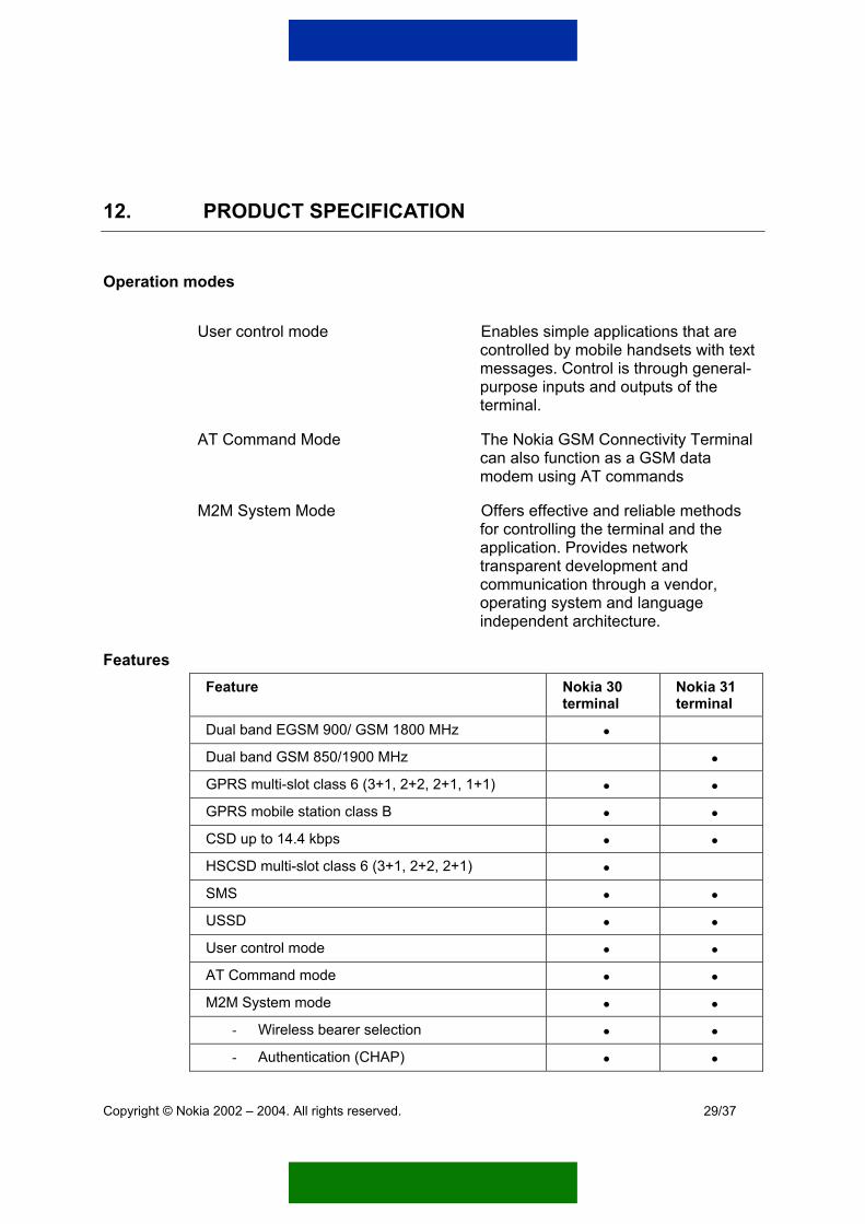
Operation modes
User control mode Enables simple applications that are controlled by mobile handsets with text messages. Control is through general-purpose inputs and outputs of the terminal.
AT Command Mode The Nokia GSM Connectivity Terminal can also function as a GSM data modem using AT commands
M2M System Mode Offers effective and reliable methods for controlling the terminal and the application. Provides network transparent development and communication through a vendor, operating system and language independent architecture.
Features Feature Nokia 30
terminal Nokia 31 terminal
Dual band EGSM 900/ GSM 1800 MHz •
Dual band GSM 850/1900 MHz •
GPRS multi-slot class 6 (3+1, 2+2, 2+1, 1+1) • •
GPRS mobile station class B • •
CSD up to 14.4 kbps • •
HSCSD multi-slot class 6 (3+1, 2+2, 2+1) •
SMS • •
USSD • •
User control mode • •
AT Command mode • •
M2M System mode • •
- Wireless bearer selection • •
- Authentication (CHAP) • •
Copyright © Nokia 2002 – 2004. All rights reserved.
29/37

Feature Nokia 30 terminal
Nokia 31 terminal
- System monitoring and alive checks • •
- Remote I/O Control • •
- Real-time clock • •
GSM security: GSM encryption, GSM security codes
• •
AutoPIN • •
Digital audio (13-bit PCM) • •
Analog audio • •
CellID • •
GSM Phase 2/2+ supplementary services • •
Messaging services SMS, USSD (MO, MT)
Audio services Digital audio interface (DAI), Analog audios
Remote I/O control 3 digital/analog inputs, 5 digital outputs
Reliability & access control GSM encryption, GSM security codes, AutoPIN, authentication, system monitoring
Real-time clock Current time and date information in real-time available in M2M System Mode where networks support it.
Cell ID Current GSM network cell ID information available where networks support it
Interfaces and connectors
Power: DC connector for the Nokia ACW-5A power supply
M2MSC: M2M System Connector is 50-pin male connector for serial communication for CORBA method calls and RS-232, power input/output, digital/analog audio, fax, and remote I/O control
Copyright © Nokia 2002 – 2004. All rights reserved.
30/37

RS-232: RS-232 interface available on M2M system connector at 3 V level. D9 female connector for standard level RS-232 available with a data adapter RS-232 accessory. Supports AT commands
UI: User interface with 3 light indicators (LEDs)
SIM-card: SIM-card reader supporting small-size SIM cards (3V)
Antenna: Internal antenna, use of external antenna supported
Accessories
Power supply (ACW-5A): A switched mode power supply (90-264 Vac)
Vehicle power supply kit (LCM-2):
Powers up the Nokia 30 terminal from a vehicle battery of 12 V or 24 V connection.
Data package: Data adapter RS-232 and data cable RS-232 with D9 connectors, Nokia 30 CD-ROM (or Nokia 31 CD-ROM)
Nokia Smart Adapter: A programmable device for connecting the Nokia GSM Connectivity Terminal to a compatible remote device through a serial interface (DB9).
Nokia GSM Connectivity Terminal Configurator:
Configurator Software for Nokia GSM Connectivity Terminals is a suite of functions that allows easy configuration of the Nokia 30 or Nokia 31 GSM Connectivity Terminal or Nokia 32 PBX Connectivity Terminal settings with your PC.
Antenna adapter (XRM-1): An adapter cable that is used between the Nokia GSM Connectivity Terminal and standard FME connector of an external antenna
Technical specification
Size 84 x 53 x 26 mm /3.31 x 2.09 x 1.02 in. Weight 65 g / 2.29oz. Volume 116 cm3 / 7.08inc3
Copyright © Nokia 2002 – 2004. All rights reserved.
31/37

Environmental temperature -10...+55 °C/+14 to 131°F
Storage temperature -40...+85 °C/-40 to 185°F Humidity range, operation 20...75 % (non-condensing) Humidity range, storage 5...95 % (non-condensing) SIM-card Small Nokia 30: Band Dual band EGSM900 & GSM1800 RF power (max.) 2W (900 MHz), 1W (1800 MHz) Nokia 31: Band Dual band GSM850 & GSM1900 RF power (max.) 2W (850 MHz), 1W (1900 MHz) Power consumption 150 mW (stand-by)
Input voltage DC plug Absolute min 6.2 V Absolute max 14.0 V
Nokia Smart Adapter AD-4 Dimensions 109x76x28.5mm/4.29x2.99x1.14inc Weight 70 g / 2.47 oz.
Processor Hitachi H8S Crystal oscillator 18.432 MHz Memory 1 MB Flash 256 kB RAM 8 kB EEPROM Serial port Fully connected DCE type
Input voltage DC plug of the Nokia GSM Connectivity Terminal
Absolute min 6.2 V Absolute max 14.0 V
Copyright © Nokia 2002 – 2004. All rights reserved.
32/37

Power supply ACW-5A
Voltage 13.5 V DC 700 mA Operating range between 90 – 264 Vac Frequency range 47 – 63 Hz Weight 70 g + cables /2.47oz. + cables Volume 100 cm3/ 6.10 inc3
Vehicle power supply kit LCM-2
Output 9.3 – 10.8 VDC 750 mA Operating range 11.3 – 32 VDC
Copyright © Nokia 2002 – 2004. All rights reserved.
33/37
APPENDIX 1: DOCUMENT LIST FOR NOKIA GSM CONNECTIVITY TERMINALS
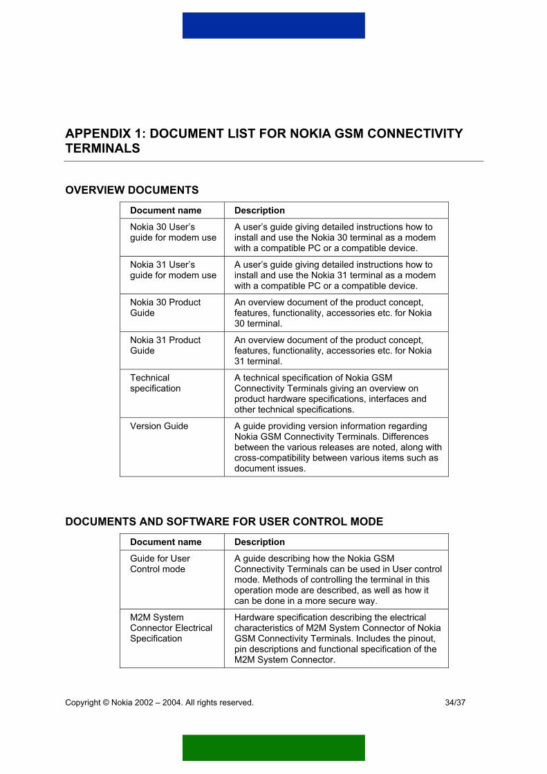
OVERVIEW DOCUMENTS
Document name Description
Nokia 30 User’s guide for modem use
A user’s guide giving detailed instructions how to install and use the Nokia 30 terminal as a modem with a compatible PC or a compatible device.
Nokia 31 User’s guide for modem use
A user’s guide giving detailed instructions how to install and use the Nokia 31 terminal as a modem with a compatible PC or a compatible device.
Nokia 30 Product Guide
An overview document of the product concept, features, functionality, accessories etc. for Nokia 30 terminal.
Nokia 31 Product Guide
An overview document of the product concept, features, functionality, accessories etc. for Nokia 31 terminal.
Technical specification
A technical specification of Nokia GSM Connectivity Terminals giving an overview on product hardware specifications, interfaces and other technical specifications.
Version Guide A guide providing version information regarding Nokia GSM Connectivity Terminals. Differences between the various releases are noted, along with cross-compatibility between various items such as document issues.
DOCUMENTS AND SOFTWARE FOR USER CONTROL MODE
Document name Description
Guide for User Control mode
A guide describing how the Nokia GSM Connectivity Terminals can be used in User control mode. Methods of controlling the terminal in this operation mode are described, as well as how it can be done in a more secure way.
M2M System Connector Electrical Specification
Hardware specification describing the electrical characteristics of M2M System Connector of Nokia GSM Connectivity Terminals. Includes the pinout, pin descriptions and functional specification of the M2M System Connector.
Copyright © Nokia 2002 – 2004. All rights reserved.
34/37

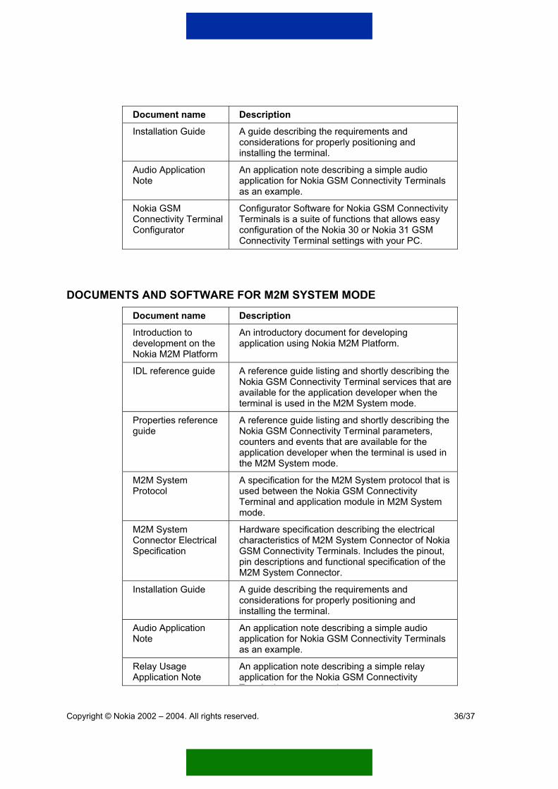
Document name Description
Installation Guide A guide describing the requirements and considerations for properly positioning and installing the terminal.
Relay Usage Application Note
An application note describing a simple relay application for the Nokia GSM Connectivity Terminals as an example.
Nokia GSM Connectivity Terminal Configurator
Configurator Software for Nokia GSM Connectivity Terminals is a suite of functions that allows easy configuration of the Nokia 30 or Nokia 31 GSM Connectivity Terminal settings with your PC.
DOCUMENTS AND SOFTWARE FOR AT COMMAND MODE
Document name Description
Nokia 30 User’s guide for modem use
A user’s guide giving detailed instructions how to install and use the Nokia 30 terminal as a modem with a compatible PC or a compatible device.
Nokia 31 User’s guide for modem use
A user’s guide giving detailed instructions how to install and use the Nokia 31 terminal as a modem with a compatible PC or a compatible device.
Modem setup for Nokia 30 GSM Connectivity Terminal
Modem Setup for Nokia 30 GSM Connectivity Terminal allows the Nokia 30 to be used as a wireless modem for your computer or compatible device. This modem functionality supports most commercially available data and fax applications as well as Internet browsers and e-mail. The setup installs PC-compatible data and fax modem drivers as well as Nokia Modem Options that let the user configure settings for data connections.
Modem setup for Nokia 31 GSM Connectivity Terminal
Modem Setup for Nokia 30 GSM Connectivity Terminal allows the Nokia 30 to be used as a wireless modem for your computer or compatible device. This modem functionality supports most commercially available data and fax applications as well as Internet browsers and e-mail. The setup installs PC-compatible data and fax modem drivers as well as Nokia Modem Options that let the user configure settings for data connections.
AT Command Guide A list of AT commands applicable for Nokia GSM Connectivity Terminals.
M2M System Connector Electrical Specification
Hardware specification describing the electrical characteristics of M2M System Connector of Nokia GSM Connectivity Terminals. Includes the pinout, pin descriptions and functional specification of the M2M System Connector.
Copyright © Nokia 2002 – 2004. All rights reserved.
35/37
Document name Description
Installation Guide A guide describing the requirements and considerations for properly positioning and installing the terminal.
Audio Application Note
An application note describing a simple audio application for Nokia GSM Connectivity Terminals as an example.
Nokia GSM Connectivity Terminal Configurator
Configurator Software for Nokia GSM Connectivity Terminals is a suite of functions that allows easy configuration of the Nokia 30 or Nokia 31 GSM Connectivity Terminal settings with your PC.
DOCUMENTS AND SOFTWARE FOR M2M SYSTEM MODE
Document name Description
Introduction to development on the Nokia M2M Platform
An introductory document for developing application using Nokia M2M Platform.
IDL reference guide A reference guide listing and shortly describing the Nokia GSM Connectivity Terminal services that are available for the application developer when the terminal is used in the M2M System mode.
Properties reference guide
A reference guide listing and shortly describing the Nokia GSM Connectivity Terminal parameters, counters and events that are available for the application developer when the terminal is used in the M2M System mode.
M2M System Protocol
A specification for the M2M System protocol that is used between the Nokia GSM Connectivity Terminal and application module in M2M System mode.
M2M System Connector Electrical Specification
Hardware specification describing the electrical characteristics of M2M System Connector of Nokia GSM Connectivity Terminals. Includes the pinout, pin descriptions and functional specification of the M2M System Connector.
Installation Guide A guide describing the requirements and considerations for properly positioning and installing the terminal.
Audio Application Note
An application note describing a simple audio application for Nokia GSM Connectivity Terminals as an example.
Relay Usage Application Note
An application note describing a simple relay application for the Nokia GSM Connectivity T i l l
Copyright © Nokia 2002 – 2004. All rights reserved.
36/37

Copyright © Nokia 2002 – 2004. All rights reserved.
37/36
Document name Description Terminals as an example.
Nokia M2M Application Development Kit Product Guide
An overview guide for Nokia M2M Application Development Kit that describes the main characteristics of it. The main features, sales packages, documentation and example applications are depicted on a general level.
Nokia GSM Connectivity Terminal Configurator
Configurator Software for Nokia GSM Connectivity Terminals is a suite of functions that allows easy configuration of the Nokia 30 or Nokia 31 GSM Connectivity Terminal settings with your PC.
Related Documents