Nokia GPRS System Feature Description
Oct 26, 2014
Welcome message from author
This document is posted to help you gain knowledge. Please leave a comment to let me know what you think about it! Share it to your friends and learn new things together.
Transcript

Nokia Siemens Networks GSM/EDGE BSS, rel. RG10(BSS), operating documentation, issue 05
Feature description
BSS09006: GPRS System Feature Description
DN7036138
Issue 3-2Approval Date 2010-06-04

2 DN7036138Issue 3-2
BSS09006: GPRS System Feature Description
Id:0900d80580782d3f
The information in this document is subject to change without notice and describes only the product defined in the introduction of this documentation. This documentation is intended for the use of Nokia Siemens Networks customers only for the purposes of the agreement under which the document is submitted, and no part of it may be used, reproduced, modified or transmitted in any form or means without the prior written permission of Nokia Siemens Networks. The documentation has been prepared to be used by professional and properly trained personnel, and the customer assumes full responsibility when using it. Nokia Siemens Networks welcomes customer comments as part of the process of continuous development and improvement of the documentation.
The information or statements given in this documentation concerning the suitability, capacity, or performance of the mentioned hardware or software products are given "as is" and all liability arising in connection with such hardware or software products shall be defined conclusively and finally in a separate agreement between Nokia Siemens Networks and the customer. However, Nokia Siemens Networks has made all reasonable efforts to ensure that the instructions contained in the document are adequate and free of material errors and omissions. Nokia Siemens Networks will, if deemed necessary by Nokia Siemens Networks, explain issues which may not be covered by the document.
Nokia Siemens Networks will correct errors in this documentation as soon as possible. IN NO EVENT WILL Nokia Siemens Networks BE LIABLE FOR ERRORS IN THIS DOCUMENTA-TION OR FOR ANY DAMAGES, INCLUDING BUT NOT LIMITED TO SPECIAL, DIRECT, INDI-RECT, INCIDENTAL OR CONSEQUENTIAL OR ANY LOSSES, SUCH AS BUT NOT LIMITED TO LOSS OF PROFIT, REVENUE, BUSINESS INTERRUPTION, BUSINESS OPPORTUNITY OR DATA,THAT MAY ARISE FROM THE USE OF THIS DOCUMENT OR THE INFORMATION IN IT.
This documentation and the product it describes are considered protected by copyrights and other intellectual property rights according to the applicable laws.
The wave logo is a trademark of Nokia Siemens Networks Oy. Nokia is a registered trademark of Nokia Corporation. Siemens is a registered trademark of Siemens AG.
Other product names mentioned in this document may be trademarks of their respective owners, and they are mentioned for identification purposes only.
Copyright © Nokia Siemens Networks 2010. All rights reserved
f Important Notice on Product Safety Elevated voltages are inevitably present at specific points in this electrical equipment. Some of the parts may also have elevated operating temperatures.
Non-observance of these conditions and the safety instructions can result in personal injury or in property damage.
Therefore, only trained and qualified personnel may install and maintain the system.
The system complies with the standard EN 60950 / IEC 60950. All equipment connected has to comply with the applicable safety standards.
The same text in German:
Wichtiger Hinweis zur Produktsicherheit
In elektrischen Anlagen stehen zwangsläufig bestimmte Teile der Geräte unter Span-nung. Einige Teile können auch eine hohe Betriebstemperatur aufweisen.
Eine Nichtbeachtung dieser Situation und der Warnungshinweise kann zu Körperverlet-zungen und Sachschäden führen.
Deshalb wird vorausgesetzt, dass nur geschultes und qualifiziertes Personal die Anlagen installiert und wartet.
Das System entspricht den Anforderungen der EN 60950 / IEC 60950. Angeschlossene Geräte müssen die zutreffenden Sicherheitsbestimmungen erfüllen.

DN7036138Issue 3-2
3
BSS09006: GPRS System Feature Description
Id:0900d80580782d3f
Table of ContentsThis document has 127 pages.
Summary of changes . . . . . . . . . . . . . . . . . . . . . . . . . . . . . . . . . . . . . . . . 9
1 GPRS. . . . . . . . . . . . . . . . . . . . . . . . . . . . . . . . . . . . . . . . . . . . . . . . . . . 111.1 GPRS data transfer protocols . . . . . . . . . . . . . . . . . . . . . . . . . . . . . . . . 151.2 Optimised GPRS Radio Resource Management. . . . . . . . . . . . . . . . . . 171.3 Frame Relay and Gb Interface. . . . . . . . . . . . . . . . . . . . . . . . . . . . . . . . 191.4 GPRS in Nokia Siemens Networks Base Stations. . . . . . . . . . . . . . . . . 21
2 Software related to GPRS . . . . . . . . . . . . . . . . . . . . . . . . . . . . . . . . . . . 222.1 Extended Uplink TBF Mode . . . . . . . . . . . . . . . . . . . . . . . . . . . . . . . . . . 222.2 GPRS Coding Schemes . . . . . . . . . . . . . . . . . . . . . . . . . . . . . . . . . . . . 232.3 Link Adaptation for GPRS . . . . . . . . . . . . . . . . . . . . . . . . . . . . . . . . . . . 262.4 Priority Class Based Quality of Service (QoS). . . . . . . . . . . . . . . . . . . . 272.5 System Level Trace . . . . . . . . . . . . . . . . . . . . . . . . . . . . . . . . . . . . . . . . 29
3 System impact of GPRS . . . . . . . . . . . . . . . . . . . . . . . . . . . . . . . . . . . . 323.1 Requirements . . . . . . . . . . . . . . . . . . . . . . . . . . . . . . . . . . . . . . . . . . . . 323.2 Restrictions . . . . . . . . . . . . . . . . . . . . . . . . . . . . . . . . . . . . . . . . . . . . . . 333.3 Impact on transmission . . . . . . . . . . . . . . . . . . . . . . . . . . . . . . . . . . . . . 343.4 Impact on BSS performance. . . . . . . . . . . . . . . . . . . . . . . . . . . . . . . . . 343.5 User interface . . . . . . . . . . . . . . . . . . . . . . . . . . . . . . . . . . . . . . . . . . . . 353.5.1 BSC MMI . . . . . . . . . . . . . . . . . . . . . . . . . . . . . . . . . . . . . . . . . . . . . . . . 353.5.2 BTS MMI . . . . . . . . . . . . . . . . . . . . . . . . . . . . . . . . . . . . . . . . . . . . . . . . 353.5.3 BSC parameters . . . . . . . . . . . . . . . . . . . . . . . . . . . . . . . . . . . . . . . . . . 353.5.4 Alarms . . . . . . . . . . . . . . . . . . . . . . . . . . . . . . . . . . . . . . . . . . . . . . . . . . 393.5.5 Measurements and counters . . . . . . . . . . . . . . . . . . . . . . . . . . . . . . . . . 403.6 Impact on Network Switching Subsystem (NSS) . . . . . . . . . . . . . . . . . . 453.7 Impact on NetAct products . . . . . . . . . . . . . . . . . . . . . . . . . . . . . . . . . . 463.8 Impact on mobile terminals . . . . . . . . . . . . . . . . . . . . . . . . . . . . . . . . . . 463.9 Impact on interfaces . . . . . . . . . . . . . . . . . . . . . . . . . . . . . . . . . . . . . . . 473.10 Interworking with other features. . . . . . . . . . . . . . . . . . . . . . . . . . . . . . . 47
4 System impact of GPRS related software . . . . . . . . . . . . . . . . . . . . . . . 544.1 System impact of Extended Uplink TBF Mode . . . . . . . . . . . . . . . . . . . 544.1.1 Requirements . . . . . . . . . . . . . . . . . . . . . . . . . . . . . . . . . . . . . . . . . . . . 544.1.2 Impact on transmission . . . . . . . . . . . . . . . . . . . . . . . . . . . . . . . . . . . . . 554.1.3 Impact on BSS performance . . . . . . . . . . . . . . . . . . . . . . . . . . . . . . . . . 554.1.4 User interface . . . . . . . . . . . . . . . . . . . . . . . . . . . . . . . . . . . . . . . . . . . . 554.1.5 Impact on Network Switching Subsystem (NSS) . . . . . . . . . . . . . . . . . . 564.1.6 Impact on NetAct products . . . . . . . . . . . . . . . . . . . . . . . . . . . . . . . . . . 564.1.7 Impact on mobile terminals . . . . . . . . . . . . . . . . . . . . . . . . . . . . . . . . . . 574.1.8 Impact on interfaces . . . . . . . . . . . . . . . . . . . . . . . . . . . . . . . . . . . . . . . 574.1.9 Interworking with other features. . . . . . . . . . . . . . . . . . . . . . . . . . . . . . . 574.2 System impact of Priority Class based Quality of Service . . . . . . . . . . . 584.2.1 Requirements . . . . . . . . . . . . . . . . . . . . . . . . . . . . . . . . . . . . . . . . . . . . 584.2.2 Impact on transmission . . . . . . . . . . . . . . . . . . . . . . . . . . . . . . . . . . . . . 59
4 DN7036138Issue 3-2
BSS09006: GPRS System Feature Description
Id:0900d80580782d3f
4.2.3 Impact on BSS performance. . . . . . . . . . . . . . . . . . . . . . . . . . . . . . . . . . 594.2.4 User interface . . . . . . . . . . . . . . . . . . . . . . . . . . . . . . . . . . . . . . . . . . . . . 594.2.5 Impact on Network Switching Subsystem (NSS) . . . . . . . . . . . . . . . . . . 614.2.6 Impact on NetAct products . . . . . . . . . . . . . . . . . . . . . . . . . . . . . . . . . . . 614.2.7 Impact on mobile terminals . . . . . . . . . . . . . . . . . . . . . . . . . . . . . . . . . . . 624.2.8 Impact on interfaces . . . . . . . . . . . . . . . . . . . . . . . . . . . . . . . . . . . . . . . . 624.2.9 Interworking with other features . . . . . . . . . . . . . . . . . . . . . . . . . . . . . . . 624.3 System impact of System Level Trace . . . . . . . . . . . . . . . . . . . . . . . . . . 634.3.1 Requirements . . . . . . . . . . . . . . . . . . . . . . . . . . . . . . . . . . . . . . . . . . . . . 634.3.2 Impact on transmission . . . . . . . . . . . . . . . . . . . . . . . . . . . . . . . . . . . . . . 644.3.3 Impact on BSS performance. . . . . . . . . . . . . . . . . . . . . . . . . . . . . . . . . . 644.3.4 User interface . . . . . . . . . . . . . . . . . . . . . . . . . . . . . . . . . . . . . . . . . . . . . 644.3.5 Impact on Network Switching Subsystem (NSS) . . . . . . . . . . . . . . . . . . 684.3.6 Impact on NetAct products . . . . . . . . . . . . . . . . . . . . . . . . . . . . . . . . . . . 684.3.7 Impact on mobile terminals . . . . . . . . . . . . . . . . . . . . . . . . . . . . . . . . . . . 694.3.8 Impact on interfaces . . . . . . . . . . . . . . . . . . . . . . . . . . . . . . . . . . . . . . . . 694.3.9 Interworking with other features . . . . . . . . . . . . . . . . . . . . . . . . . . . . . . . 69
5 Requirements for GPRS . . . . . . . . . . . . . . . . . . . . . . . . . . . . . . . . . . . . . 705.1 Packet Control Unit (PCU) . . . . . . . . . . . . . . . . . . . . . . . . . . . . . . . . . . . 705.2 Gb interface functionality . . . . . . . . . . . . . . . . . . . . . . . . . . . . . . . . . . . . 735.3 Additional GPRS hardware needed in BSCi and BSC2i. . . . . . . . . . . . . 75
6 Radio network management for GPRS. . . . . . . . . . . . . . . . . . . . . . . . . . 766.1 Routing Area . . . . . . . . . . . . . . . . . . . . . . . . . . . . . . . . . . . . . . . . . . . . . . 766.2 PCU selection algorithm . . . . . . . . . . . . . . . . . . . . . . . . . . . . . . . . . . . . . 77
7 Gb interface configuration and state management . . . . . . . . . . . . . . . . . 797.1 Protocol stack of the Gb interface. . . . . . . . . . . . . . . . . . . . . . . . . . . . . . 797.2 Load sharing function . . . . . . . . . . . . . . . . . . . . . . . . . . . . . . . . . . . . . . . 807.3 NS-VC management function . . . . . . . . . . . . . . . . . . . . . . . . . . . . . . . . . 817.4 BVC management function . . . . . . . . . . . . . . . . . . . . . . . . . . . . . . . . . . . 847.5 Recovery in restart and switchover. . . . . . . . . . . . . . . . . . . . . . . . . . . . . 86
8 Radio resource management . . . . . . . . . . . . . . . . . . . . . . . . . . . . . . . . . 888.1 Territory method . . . . . . . . . . . . . . . . . . . . . . . . . . . . . . . . . . . . . . . . . . . 888.2 Circuit switched traffic channel allocation in GPRS territory . . . . . . . . . . 948.3 BTS selection for packet traffic . . . . . . . . . . . . . . . . . . . . . . . . . . . . . . . . 958.4 Quality of Service . . . . . . . . . . . . . . . . . . . . . . . . . . . . . . . . . . . . . . . . . . 968.5 Channel allocation and scheduling . . . . . . . . . . . . . . . . . . . . . . . . . . . . . 978.6 Quality Control . . . . . . . . . . . . . . . . . . . . . . . . . . . . . . . . . . . . . . . . . . . 1038.7 MS Multislot Power Reduction (PCU2) . . . . . . . . . . . . . . . . . . . . . . . . . 1048.8 Error situations in GPRS connections. . . . . . . . . . . . . . . . . . . . . . . . . . 105
9 GPRS radio connection control. . . . . . . . . . . . . . . . . . . . . . . . . . . . . . . 1089.1 Radio channel usage . . . . . . . . . . . . . . . . . . . . . . . . . . . . . . . . . . . . . . 1089.2 Data Transfer Protocols and Connections . . . . . . . . . . . . . . . . . . . . . . 1099.3 Paging. . . . . . . . . . . . . . . . . . . . . . . . . . . . . . . . . . . . . . . . . . . . . . . . . . 1099.4 Mobile terminated TBF (GPRS) . . . . . . . . . . . . . . . . . . . . . . . . . . . . . . 1119.5 Mobile originated TBF. . . . . . . . . . . . . . . . . . . . . . . . . . . . . . . . . . . . . . 113

DN7036138Issue 3-2
5
BSS09006: GPRS System Feature Description
Id:0900d80580782d3f
9.6 Suspend and resume GPRS . . . . . . . . . . . . . . . . . . . . . . . . . . . . . . . . 1159.7 Flush . . . . . . . . . . . . . . . . . . . . . . . . . . . . . . . . . . . . . . . . . . . . . . . . . . 1169.8 Cell selection and re-selection . . . . . . . . . . . . . . . . . . . . . . . . . . . . . . . 1169.9 Traffic administration . . . . . . . . . . . . . . . . . . . . . . . . . . . . . . . . . . . . . . 1179.10 Coding scheme selection in GPRS . . . . . . . . . . . . . . . . . . . . . . . . . . . 1199.11 Power control . . . . . . . . . . . . . . . . . . . . . . . . . . . . . . . . . . . . . . . . . . . . 1269.12 MS Radio Access Capability update . . . . . . . . . . . . . . . . . . . . . . . . . . 126
10 Implementing GPRS . . . . . . . . . . . . . . . . . . . . . . . . . . . . . . . . . . . . . . 12710.1 Implementing GPRS overview . . . . . . . . . . . . . . . . . . . . . . . . . . . . . . . 127
6 DN7036138Issue 3-2
BSS09006: GPRS System Feature Description
Id:0900d80580782d3f
List of FiguresFigure 1 GPRS network seen by another data network . . . . . . . . . . . . . . . . . . . . 13Figure 2 GPRS architecture . . . . . . . . . . . . . . . . . . . . . . . . . . . . . . . . . . . . . . . . . 13Figure 3 Transmission plane. . . . . . . . . . . . . . . . . . . . . . . . . . . . . . . . . . . . . . . . . 15Figure 4 Transmission and reception data flow . . . . . . . . . . . . . . . . . . . . . . . . . . 17Figure 5 GPRS DCH dedicated channels . . . . . . . . . . . . . . . . . . . . . . . . . . . . . . . 17Figure 6 Example of a GPRS capable cell . . . . . . . . . . . . . . . . . . . . . . . . . . . . . . 18Figure 7 Air interface traffic management . . . . . . . . . . . . . . . . . . . . . . . . . . . . . . . 19Figure 8 BSC - SGSN interface . . . . . . . . . . . . . . . . . . . . . . . . . . . . . . . . . . . . . . 20Figure 9 Gb logical structure . . . . . . . . . . . . . . . . . . . . . . . . . . . . . . . . . . . . . . . . . 21Figure 10 Gb interface . . . . . . . . . . . . . . . . . . . . . . . . . . . . . . . . . . . . . . . . . . . . . . 21Figure 11 GPRS Coding Schemes . . . . . . . . . . . . . . . . . . . . . . . . . . . . . . . . . . . . . 23Figure 12 Example of transmission turns . . . . . . . . . . . . . . . . . . . . . . . . . . . . . . . . 28Figure 13 Trace activation/deactivation and report generation . . . . . . . . . . . . . . . . 29Figure 14 Architecture of the GPRS network and related network elements . . . . . 30Figure 15 PCU connections to BTS and SGSN when Frame Relay is used . . . . . 72Figure 16 Protocol stack of the Gb interface. . . . . . . . . . . . . . . . . . . . . . . . . . . . . . 74Figure 17 Gb interface between the BSC and SGSN when Frame Relay (FR) is used
75Figure 18 Relationship of Routing Areas and PCUs . . . . . . . . . . . . . . . . . . . . . . . . 76Figure 19 The protocol stack on the Gb interface . . . . . . . . . . . . . . . . . . . . . . . . . . 79Figure 20 Territory method in BSC . . . . . . . . . . . . . . . . . . . . . . . . . . . . . . . . . . . . . 89Figure 21 GPRS territory upgrade when a timeslot is cleared for GPRS use with an
intra cell handover. . . . . . . . . . . . . . . . . . . . . . . . . . . . . . . . . . . . . . . . . . 91Figure 22 Dynamic Allocation MAC mode . . . . . . . . . . . . . . . . . . . . . . . . . . . . . . 101Figure 23 Extended Dynamic Allocation MAC mode . . . . . . . . . . . . . . . . . . . . . . 102Figure 24 Uplink power control . . . . . . . . . . . . . . . . . . . . . . . . . . . . . . . . . . . . . . . 126

DN7036138Issue 3-2
7
BSS09006: GPRS System Feature Description
Id:0900d80580782d3f
List of TablesTable 1 Required additional or alternative hardware or firmware . . . . . . . . . . . 24Table 2 Required software by network elements . . . . . . . . . . . . . . . . . . . . . . . . 24Table 3 Required software . . . . . . . . . . . . . . . . . . . . . . . . . . . . . . . . . . . . . . . . . 32Table 4 Impact of GPRS on BSC units . . . . . . . . . . . . . . . . . . . . . . . . . . . . . . . 34Table 5 Counters of Packet Control Unit Measurement related to GPRS . . . . . 41Table 6 Counters of RLC Blocks per TRX Measurement . . . . . . . . . . . . . . . . . 41Table 7 Counters of Frame Relay Measurement . . . . . . . . . . . . . . . . . . . . . . . . 42Table 8 Counters of Coding Scheme Measurement . . . . . . . . . . . . . . . . . . . . . 43Table 9 Counters of Quality of Service Measurement related to GPRS . . . . . . 44Table 10 Counters of GPRS RX Level and Quality Measurement . . . . . . . . . . . 44Table 11 Counters of PCU Utilization Measurement . . . . . . . . . . . . . . . . . . . . . . 45Table 12 Required additional or alternative hardware or firmware. . . . . . . . . . . . 54Table 13 Required software . . . . . . . . . . . . . . . . . . . . . . . . . . . . . . . . . . . . . . . . . 54Table 14 Impact of Extended Uplink TBF Mode on BSC units . . . . . . . . . . . . . . 55Table 15 Counters of 72 Packet Control Unit Measurement . . . . . . . . . . . . . . . . 56Table 16 Required additional or alternative hardware or firmware . . . . . . . . . . . 58Table 17 Required software . . . . . . . . . . . . . . . . . . . . . . . . . . . . . . . . . . . . . . . . . 58Table 18 Impact of Priority Class based Quality of Service on BSC units . . . . . . 59Table 19 Radio network parameters for Priority Based Scheduling . . . . . . . . . . 60Table 20 Counters of Quality of Service Measurement . . . . . . . . . . . . . . . . . . . . 61Table 21 Required additional or alternative hardware or firmware . . . . . . . . . . . 63Table 22 Required software . . . . . . . . . . . . . . . . . . . . . . . . . . . . . . . . . . . . . . . . . 63Table 23 Impact of System Level Trace on BSC units . . . . . . . . . . . . . . . . . . . . 64Table 24 Counters of TBF Observation for GPRS Trace . . . . . . . . . . . . . . . . . . . 64Table 25 Counters of GPRS Cell Re-Selection Report . . . . . . . . . . . . . . . . . . . . 66Table 26 Counters of GPRS RX Level and Quality Report . . . . . . . . . . . . . . . . . 67Table 27 CS and MCS codecs in the initial coding scheme and new MCS fields 68Table 28 Nokia Siemens Networks GSM/EDGE PCU product family . . . . . . . . . 70Table 29 PCUs in BSC product variants . . . . . . . . . . . . . . . . . . . . . . . . . . . . . . . 70Table 30 PCU maximum connectivity per logical PCU . . . . . . . . . . . . . . . . . . . . 71Table 31 NS-VC operational states . . . . . . . . . . . . . . . . . . . . . . . . . . . . . . . . . . . 81Table 32 NS-VC reset cases . . . . . . . . . . . . . . . . . . . . . . . . . . . . . . . . . . . . . . . . 83Table 33 BVC operational states . . . . . . . . . . . . . . . . . . . . . . . . . . . . . . . . . . . . . 84Table 34 BVC blocking cases . . . . . . . . . . . . . . . . . . . . . . . . . . . . . . . . . . . . . . . 85Table 35 BVC reset cases . . . . . . . . . . . . . . . . . . . . . . . . . . . . . . . . . . . . . . . . . . 86Table 36 Defining the margin of idle TCH/Fs . . . . . . . . . . . . . . . . . . . . . . . . . . . . 92Table 37 Defining the margin of idle TCHs, % . . . . . . . . . . . . . . . . . . . . . . . . . . . 94Table 38 GMSK Mean BEP Limit for UL . . . . . . . . . . . . . . . . . . . . . . . . . . . . . . 105Table 39 RX Quality Limit for UL . . . . . . . . . . . . . . . . . . . . . . . . . . . . . . . . . . . . 105Table 40 Supported Network Operation Modes . . . . . . . . . . . . . . . . . . . . . . . . . 110
8 DN7036138Issue 3-2
BSS09006: GPRS System Feature Description
Id:0900d80580782d3f

DN7036138Issue 3-2
9
BSS09006: GPRS System Feature Description Summary of changes
Id:0900d80580782d39
Summary of changesChanges between document issues are cumulative. Therefore, the latest document issue contains all changes made to previous issues.
Changes made between issues 3-2 and 3-1Information on Flexi Multiradio and BTSplus support have been added.
Information regarding the feature BSS21238 “Merged P-&E-GSM900” has been updated in section Interworking with other features in the chapter System impact of GPRS.
Changes made between issues 3-1 and 3-0Information on InSite BTS has been removed.
Changes made between issues 3-0 and 2-0GPRS
References have been updated.
Information on PCU2 capacity has been updated.
GPRS Coding Schemes
Software versions have been updated to S14 level.
System impact of GPRS
Software versions have been updated to S14 level.
System impact of Extended Uplink TBF Mode
Software versions have been updated to S14 level.
System impact of Priority Class based Quality of Service
Software versions have been updated to S14 level.
System impact of System Level Trace
Software versions have been updated to S14 level.
Requirements for GPRS
Information on Flexi BSC and PCU2-E has been added. The capacity information has been updated. Internal PCU2-E restrictions have been added.
Changes made between issues 2-0 and 1-1The contents of GPRS in BSC have been merged into this document.
Chapters Support for PBCCH/PCCCH and System impact of Support for PBCCH/PCCCH have been removed.
Chapters Dynamic Abis and System Impact of Dynamic Abis have been moved from this document to Dynamic Abis.
Chapter Software related to GPRS has been modified to only include descriptions of such GPRS-related features that do not have their own separate description documents.
GPRS Coding Schemes
Support for 2nd generation BTS and PrimeSite BTS has been removed.
System Level Trace
Section System Level Trace in BSC has been moved here from GPRS in BSC.
10 DN7036138Issue 3-2
BSS09006: GPRS System Feature Description
Id:0900d80580782d39
Summary of changes
System impact of GPRS
Support for 2nd generation BTS and PrimeSite BTS has been removed. 91 PBCCH Availability Measurement has been removed. Extended Cell Range restriction has been removed.
Section Restrictions has been moved here from GPRS in BSC.
110 PCU Utilization Measurement has been added. New counters have been added to 72 Packet Control Unit Measurement.
Interworking with EGSM 900 - PGSM 900 BTS has been updated. A reference to GPRS/EDGE Support for PGSM-EGSM BTS was added.
The name of alarm 3273 (E)GPRS TERRITORY FAILURE has been updated to 3273 GPRS/EDGE TERRITORY FAILURE.
System impact of Priority Class based Quality of Service
Support for 2nd generation BTS and PrimeSite BTS has been removed.
System impact of System Level Trace
Support for 2nd generation BTS and PrimeSite BTS has been removed.
New counters have been added to 25 TBF Observation for GPRS Trace.
System impact of Extended Uplink TBF Mode
Support for 2nd generation BTS and PrimeSite BTS has been removed. New PRFILE parameters have been added.
Requirements for GPRS
The chapter has been moved here from GPRS in BSC. Information on PCCCH/PBCCH has been removed.
Radio network management for GPRS
The chapter has been moved here from (E)GPRS in BSC. A reference to Packet Control Unit (PCU2) Pooling has been added. Information on PCCCH/PBCCH has been removed.
Gb interface configuration and state management
The chapter has been moved here from GPRS in BSC. A reference to Multipoint Gb Interface has been added.
Radio resource management
The chapter has been moved here from GPRS in BSC. Information on PCCCH/PBCCH has been removed.
GPRS radio connection control
The chapter has been moved here from GPRS in BSC. Section PACKET PSI STATUS procedure has been removed. Information on PCCCH/PBCCH has been removed.
The GPRS implementing instructions have been combined into a single chapter.
Changes made between issues 1-1 and 1-0Changes made between issues 1-1 and 1-0 lists the changes made to the document after the GSM/EDGE BSS, Rel. BSS12, System Documentation pilot release. The fol-lowing changes have been made:
• PCU2 support for PBCCH/PCCCH has been removed from chapter Packet Control Unit in BSC.

DN7036138Issue 3-2
11
BSS09006: GPRS System Feature Description GPRS
Id:0900d8058078e154
1 GPRSGeneral Packet Radio Service (GPRS) provides packet data radio access for GSM mobile phones. It upgrades GSM data services to allow an interface with Local Area Networks (LANs), Wide Area Networks (WANs) and the Internet.
GPRS makes the radio interface usage more efficient:
• GPRS enables a fast method for reserving radio channels • GPRS uses the same resources with circuit switched connection by sharing the
overhead capacity • GPRS provides immediate connectivity and high throughput.
On a general level, GPRS connections use the resources only for a short period of time when sending or receiving data:
• in a circuit-switched system, the line is occupied even when no data is transferred • in a packet-switched system, the resources are released so they can be used by
other subscribers.
GPRS is therefore well adapted to the bursty nature of data applications. GPRS has minimal effects on the handling of circuit switched calls, but the interoperability of existing circuit switched functionalities needs to be taken into account.
GPRS uses statistical multiplexing instead of static time division multiplexing: when the user is ready to receive new data, the terminal sends a request, and resources are again reserved only for the duration of transmitting the request and initiating a second data transfer. The data to be transferred is encapsulated into short packets with a header containing the originating and destination address. No pre-set time slots are used. Instead, network capacity is allocated when needed and released when not needed.
GPRS offers a very flexible range of bitrates, from less than 100 bit/s to over 100 kbit/s. Applications that need less than one time slot benefit from GPRS's ability to share one time slot among several users. Moreover, the high bitrates that GPRS provides by using multiple time slots give short response times, even if a lot of data is transmitted.
The main functions of the BSC with GPRS are to:
• manage GPRS-specific radio network configuration • control access to GPRS radio resources • share radio resources between GPRS and circuit switched use • handle signalling between the MS, BTS and Serving GPRS Support Node (SGSN) • transfer GPRS data.
BSC operational software includes support for GPRS coding schemes CS-1 and CS-2. Support for coding schemes CS-3 and CS-4 is an application software product that requires PCU2 and Dynamic Abis.
GPRS is licence key controlled. For more information, see Licence Management in BSC.
Benefits of GPRSGPRS offers the following additional benefits for the operators/end users:
• resources are used more efficiently, thus there is less idle time • circuit switched traffic is prioritised, but quality is guaranteed by reserving time slots
for GPRS traffic only • new services, application, and businesses for the operators

12 DN7036138Issue 3-2
BSS09006: GPRS System Feature Description
Id:0900d8058078e154
GPRS
• fast connection set-up for end users • high bit rate in data bursts • possibility of being charged only for transferred data • generally, any service that can be run on top of IP protocols (the UDP or TCP trans-
fer) is supported by the Nokia Siemens Networks GPRS solution (taking into account data rate and delay requirements).
An investment in the GPRS infrastructure is an investment in future services. GPRS paves the way and is already part of the third generation (3G) network infrastructure. Migration to 3G comprises deployment of the new WCDMA radio interface – served by the GSM and GPRS core networks. Many of the 3G services are based on IP, and the GPRS Core network is the key step of introducing the IP service platform into the present GSM networks.
When migrating to 3G services, preserving the Core Network investments is a top prior-ity. Introducing UMTS will complement the GSM network – not replace it.
Required network changesNokia Siemens Networks offers a total end-to-end General Packet Radio Service (GPRS) solution including the GPRS core, network management, and charging gateway with high capacity, scalability, and carrier class availability. As a part of the GPRS solu-tion, the Nokia Siemens Networks BSS offers GPRS support in the BSS with powerful radio resource management algorithms, optimised BSS network topology, and trans-mission solutions to ensure an optimal investment to operators and high capacity and quality service for end users.
While the current GSM system was originally designed with an emphasis on voice ses-sions, the main objective of the GPRS is to offer access to standard data networks such as LAN using the TCP/IP protocol. These networks consider the GPRS to be a normal subnetwork, as seen in the figure below. A gateway in the GPRS network acts as a router and hides GPRS-specific features from the external data network. WAP (Wireless Application Protocol) based services see the GPRS as one carrier (UDP). Wireless Markup Language (WML) based services in the GPRS can be accessed using the standard WAP gateways. The WAP is essential in creating applications that are 'use-able' in the mobile environment (for example, small screen display, low data rates).

DN7036138Issue 3-2
13
BSS09006: GPRS System Feature Description GPRS
Id:0900d8058078e154
Figure 1 GPRS network seen by another data network
GPRS is the first GSM Phase 2+ service that requires major changes in the network infrastructure. In addition to the current GSM entities, GPRS is based on a number of new network elements:
• Serving GPRS Support Nodes (SGSN) • GPRS backbone • Legal Interception Gateway (LIG).
Figure 2 GPRS architecture
Along with the new network elements, the following functions are needed:
• GPRS-specific mobility management • Network management capable of handling the GPRS-specific elements • A new radio interface for packet traffic

14 DN7036138Issue 3-2
BSS09006: GPRS System Feature Description
Id:0900d8058078e154
GPRS
• New security features for the GPRS backbone and a new ciphering algorithm • New MAP and GPRS-specific signalling.
Related topics in GPRS System Feature Description
• Extended Uplink TBF Mode • GPRS Coding Schemes • Link Adaptation for GPRS • Priority Class Based Quality of Service (QoS) • System Level Trace • System impact of GPRS • System impact of Extended Uplink TBF Mode • System impact of Priority Class based Quality of Service • System impact of System Level Trace • Requirements for GPRS • Radio network management for GPRS • Gb interface configuration and state management • Radio resource management • GPRS radio connection control • Implementing GPRS overview
Other related topicsDescriptions
• BSS21228: Downlink Dual Carrier • BSS20088: Dual Transfer Mode • BSS10045: Dynamic Abis • BSS20094: Extended Cell for GPRS/EDGE • BSS20089: Extended Dynamic Allocation • BSS10103: Gb over IP • BSS20084: High Multislot Classes • BSS20394: Inter-System Network-Controlled Cell Re-selection • BSS20086: Multipoint Gb Interface • BSS115006: Network-Assisted Cell Change • BSS11112: Network-Controlled Cell Re-selection • BSS20106: Packet Control Unit (PCU2) Pooling
Instructions
• Activating and testing BSS9006: GPRS
Reference
• EA - Adjacent Cell Handling • EE - Base Station Controller Parameter Handling in BSC • EG - GSM Timer and BSC Parameter Handling • EQ - Base Transceiver Station Handling in BSC • ER - Transceiver Handling • ES - Abis Interface Configuration • EU - Power Control Parameter Handling • FX - Gb Interface Handling
DN7036138Issue 3-2
15
BSS09006: GPRS System Feature Description GPRS
Id:0900d8058078e154
• PCU2 Service Terminal Commands • 25 TBF Observation for GPRS Trace • 27 GPRS Cell Re-selection Report • 28 GPRS RX Level and Quality Report • 72 Packet Control Unit Measurement • 73 RLC Blocks per TRX Measurement • 74 Frame Relay Measurement • 76 Dynamic Abis Measurement • 79 Coding Scheme Measurement • 90 Quality of Service Measurement • 95 GPRS Cell Re-selection Measurement • 96 GPRS RX Level and Quality Measurement • 98 Gb Over IP Measurement • 105 PS DTM Measurement • 106 CS DTM Measurement • 110 PCU Utilisation Measurement • BSS Radio Network Parameter Dictionary • PAFILE Timer and Parameter List • PRFILE and FIFILE Parameter List
1.1 GPRS data transfer protocols
Figure 3 Transmission plane
The GSM RF is the normal GSM physical radio layer. The Radio Link Control (RLC) function offers a reliable radio link to the upper layers. The Medium Access Control (MAC) function handles the channel allocation and the multiplexing, that is, the use of physical layer functions. The RLC and the MAC together form the OSI Layer 2 protocol for the Um interface. The Logical Link Control (LLC) layer offers a secure and reliable logical link between the MS and the SGSN to upper layers and is independent of the lower layers. The LLC layer has two transfer modes, the acknowledged and unacknowl-edged. The LLC conveys signalling, SMS, and SNDCP packets. The Subnetwork Dependent Convergence Protocol (SNDCP) is a mapping and compression function between the network layer and lower layers. It also performs segmentation, re-assem-bly, and multiplexing.

16 DN7036138Issue 3-2
BSS09006: GPRS System Feature Description
Id:0900d8058078e154
GPRS
The Base Station System GPRS Protocol (BSSGP) transfers control information and data between a BSS and an SGSN. The Network Services relays the BSSGP packets over the Gb interface and has load sharing and redundancy on top of Frame Relay. The L1bis is a vendor-dependent OSI Layer 1 protocol. The Relay function relays LLC PDUs (Protocol Data Units) between the LLC and BSSGP.
The Packet Control Unit is responsible for the following GPRS MAC and RLC layer func-tions as defined in 3GPP TS 43.064:
• LLC layer PDU segmentation into RLC blocks for downlink transmission • LLC layer PDU re-assembly from RLC blocks for uplink transmission • PDCH scheduling functions for the uplink and downlink data transfers • PDCH uplink ARQ functions, including RLC block ack/nack • PDCH downlink ARQ function, including buffering and retransmission of RLC blocks • Channel access control functions, for example, access requests and grants • Radio channel management functions, for example, power control, congestion
control, broadcast control information, etc. • The Channel Codec Unit (CCU) takes care of the channel coding functions,
including FEC and interleaving • Radio channel measurement functions, including received quality level, received
signal level, and information related to timing advance measurements.
For more information on the PCU, see Packet Control Unit (PCU).
The Network Protocol Data Units (N-PDU) are segmented into the Subnetwork Protocol Data Units (SN-PDU) by the Subnetwork Dependent Convergence (SNDC) protocol, and SN-PDUs are encapsulated into one or several LLC frames. LLC frames are of variable length. The maximum size of the LLC frame is 1600 octets minus GP protocol control information. See 3GPP TS 23.060 for information on SNDC and LLC. The details on SNDC can be found in 3GPP TS 44.065 and the details on LLC in 3GPP TS 44.064. LLC frames are segmented into RLC Data Blocks. In the RLC/MAC layer, a selective ARQ protocol (including block numbering) between the MS and the network provides retransmission of erroneous RLC Data Blocks. When a complete LLC frame is success-fully transferred across the RLC layer, it is forwarded to the LLC layer.
DN7036138Issue 3-2
17
BSS09006: GPRS System Feature Description GPRS
Id:0900d8058078e154
Figure 4 Transmission and reception data flow
1.2 Optimised GPRS Radio Resource ManagementThe Nokia Siemens Networks BSS offers dynamic algorithms and parameters to optimise the use of radio resources. A dynamic and flexible GPRS radio resource man-agement is important in effective usage of the Air interface capacity to ensure maximum and secure data throughput. The limited radio resources must be used effectively.
The figure below introduces the dedicated GPRS DCH channels:
Figure 5 GPRS DCH dedicated channels
GPRS packets are sent uni-directionally; uplink and downlink are separate resources. An MS can also have a bi-directional connection while using GPRS, by having simulta-neous uplink and downlink packet transfers. A Temporary Block Flow (TBF) is made for every new data flow. One or more packet data traffic channels (PDTCHs) are allocated for the TBF. The TBF is used to send RLC/MAC blocks carrying one or more LLC PCUs.

18 DN7036138Issue 3-2
BSS09006: GPRS System Feature Description
Id:0900d8058078e154
GPRS
The TBF reservations of PDTCHs are released when all the RLC/MAC blocks have been sent successfully.
Basically all TBFs have the same priority, that is, all users and all applications get the same service level. The needs of different applications differ and mechanisms to have separate service levels are required. ETSI specifications define QoS functionality which gives the possibility to differentiate TBFs by delay, throughput and priority. Priority Based Scheduling is introduced as a first step towards QoS. With Priority Based Sched-uling the operator can give users different priorities so that higher priority users will get better service than lower priority users. There will be no extra blocking to any user, only the experienced service quality changes.
Packet Associated Control Channel (PACCH) conveys signalling information related to a given MS. The PACCH is a bi-directional channel and is located in the PDCH. It trans-mits signalling in both directions although data is transmitted (PDTCH) only in the assigned direction.
Multiple MSS can share one PDTCH, but the PDTCH is dedicated to one MS (TBF) at a time. This means that the PDTCH is reserved for multiple TBFs, but one TBF is receiv-ing or sending at a time. All the GPRS TBFs allocated to a PDTCH are served equally. The number of TSLs allocated for a multislot MS is determined by the mobile's multislot capability and network resources. Reallocations are done when the transfer mode is changed between uni-directional (only uplink or downlink data transfer) and bi-direc-tional (simultaneous uplink and downlink data transfer).
All the full rate or dual rate traffic channels are GPRS capable. With the GPRS solution, the operator can define dynamically multiple parameters related to network configura-tion, such as:
• GPRS capacity cell by cell and TRX by TRX • GPRS only traffic channels (Dedicated GPRS capacity) • Default amount of GPRS capable traffic channels (Default GPRS capacity) and • Whether BCCH TRX or non-BCCH TRX is preferred for GPRS.
The adjustable parameters help the network planners to control and optimise GPRS radio resources.
Figure 6 Example of a GPRS capable cell
The BSS is upgraded with enhanced RLC/MAC protocols and TRAU for the radio and Abis interfaces. Circuit Switched (CS) traffic has priority over Packet Switched (PS) traffic. In a CS congestion situation, the CS may use the Default GPRS traffic channels, but Dedicated GPRS traffic channels are reserved to carry PS traffic.
TRX 1
TRX 2
BCCH
DefaultGPRS Capacity
DedicatedGPRS
Capacity
AdditionalGPRS
Capacity
Territory border moves based onCircuit Switched and GPRS traffic load
GPRSTerritory
CircuitSwitchedTerritory
MaxGPRS
Capacity

DN7036138Issue 3-2
19
BSS09006: GPRS System Feature Description GPRS
Id:0900d8058078e154
The default GPRS capacity determines the number of traffic channels (TCHs), which are always switched to the PCU when allowed by CS traffic load. With these TCHs, the operator can supply the need for fast GPRS channel reservations for the first data packets. During peak GPRS traffic periods, additional channels are switched to GPRS use, if the CS traffic load allows it.
Figure 7 Air interface traffic management
Dedicated, default, and additional GPRS TCHs form a GPRS pool consisting of consec-utive radio interface timeslots. When the GPRS pool is upgraded, intra-cell handovers of CS connections may be needed to allow for the selection of consecutive timeslots for GPRS use. New CS connections may be allocated to a TCH in the GPRS pool only when all the TCHs not belonging to the GPRS pool are occupied.
IUO super reuse frequencies are not used for GPRS traffic, but the feature itself can be used to release resources for GPRS usage. In cells where Base Band Frequency Hopping is in use, TSL 0 is not used for GPRS traffic.
When Extended Cell for GPRS/EDGE application software is used, the Extended Cell GPRS channels (EGTCH) in Extended TRX (E-TRX) are reserved only for fixed GPRS traffic and dynamic GPRS radio resource management is not used for them at all. For more information, see Extended Cell for GPRS/EDGE.
1.3 Frame Relay and Gb InterfaceGb is the interface between a BSC and an SGSN. It is implemented using either Frame Relay or IP. For more information on Gb over IP, see Gb over IP. Frame Relay can be either point-to-point (PCU–SGSN), or there can be a Frame Relay network located between the BSC and SGSN. The protocol stack comprises BSSGB, NS, and L1. Frame Relay as stated in standards is a part of the Network Service (NS) layer. On top of the physical layer in the Gb-interface, the direct point-to-point Frame Relay connections or intermediate Frame Relay network can be used. The physical layer is implemented as one or several PCM-E1 lines with G.703 interface. The FR network will be comprised of third-party off-the-shelf products. The following figure displays examples of Gb interface transmission solutions:
20 DN7036138Issue 3-2
BSS09006: GPRS System Feature Description
Id:0900d8058078e154
GPRS
Figure 8 BSC - SGSN interface
In the first solution (1) spare capacity of Ater and A interfaces is used for the Gb. The Gb timeslots are transparently through connected in the TCSM and in the MSC. If free capacity exists, it is best to multiplex all Gb traffic to the same physical link to achieve possible transmission savings. In many cases, the SGSN will be located in the MSC site, and thus the multiplexing has to take place there as well. Normal cross-connect equip-ment, for example, Nokia Siemens Networks DN2 can be used for that purpose.
The second solution (2) represents any transmission network that provides a point-to-point connection between the BSC and the SGSN. In the third solution (3) Frame Relay network is used. The Gb interface allows the exchange of signalling information and user data. The Gb interface allows many users to be multiplexed over the same physical resources.
At least one timeslot of 64 kbps is needed for each activated PCU bearer. One PCU1 can handle a maximum of 64 BTSs and 128 TRXs. One PCU2-D/PCU2-U can handle a maximum of 128 BTSs and 256 TRXs. One PCU2-E can handle a maximum of 384 BTSs and 1024 TRXs. This capacity cannot be shared with other cells connected to other PCUs in the BSC so there is no pooling. The PCU has to be installed into every BCSU for redundancy reasons, but the FR bearer has to be connected only to the active ones. Considering the transmission protection, it also needs to be decided whether two Frame Relay bearers are needed for each PCU using different ETs (external 2Ms) or if the transmission is protected with cross connection equipment.
It is possible to multiplex more than one Gb interface directly to the SGSN, or multiplex them on the A interface towards the MSC and cross-connect them to the SGSN from there. The 2M carrying the Gb timeslots can be one of the BSC's existing ETs, or an ET can be dedicated to the Gb interface.
The Gb interface allows the exchange of signalling information and user data. It also allows many users to be multiplexed over the same physical resources. The logical structure of the point-to-point Gb interface is presented in the following figure:
DN7036138Issue 3-2
21
BSS09006: GPRS System Feature Description GPRS
Id:0900d8058078e154
Figure 9 Gb logical structure
In the BSC, each PCU represents one Network Service Entity with own Identifier (NSEI). Each PCU can have one to four (ffs) FR bearer channels. The Access Rate of a FR Bearer Channel can be configured in 64kbit steps. Each Bearer channel carries one to four Network Service Virtual Connections (NS-VC). Each BTS has a BSSGP Virtual Connection of its own. The NSE takes care of the multiplexing of BSSGP Virtual Con-nections into the NS Virtual Connections and load sharing between the different NS Virtual Connections (= Bearer Channels).
The following figure displays the Gb protocol layers:
Figure 10 Gb interface
1.4 GPRS in Nokia Siemens Networks Base StationsRadio resources are allocated by the BSC (PCU). The BCCH/CCCH is scheduled by the BTS; messages are routed via TRXSIG link between the BTS and BSC. GPRS data itself is transparent to the BTS; routed via TCH channels in Abis.
The CCU (Channel Coding Unit) in the BTS DSP performs channel coding for the fol-lowing rates:
• CS-1 (Channel Coding Scheme 1) - 9.05 kbps • CS-2 (Channel Coding Scheme 2) - 13.4 kbps • CS-3 (Channel Coding Scheme 3) - 14.4 kbps • CS-4 (Channel Coding Scheme 4) - 20.0 kbps
In Packet Transfer Mode, the MS will use the continuous timing advance update proce-dure. The procedure is carried out on all PDCH timeslots. The mapping in time of these logical channels is defined by a multi-frame structure. It consists of 52 TDMA frames, divided into 12 blocks (of four frames) and four idle frames.

22 DN7036138Issue 3-2
BSS09006: GPRS System Feature Description
Id:0900d8058077eaf4
Software related to GPRS
2 Software related to GPRS
2.1 Extended Uplink TBF ModeWith Extended Uplink TBF Mode the uplink TBF may be maintained during temporary inactive periods, where the mobile station has no data to send. Without Extended Uplink TBF Mode a new uplink TBF has to be established after every inactive period.
When both the MS and the network support Extended Uplink TBF Mode, the release of the uplink TBF can be delayed even if the MS occasionally has nothing to transmit. Right after the MS has new data to send, the same uplink TBF can be used and data trans-mission can be reactivated.
Extended Uplink TBF Mode requires 3GPP Rel. 4 GERAN feature package 1 mobile stations.
Benefits of the Nokia Siemens Networks solution
• With Extended UL TBF Mode the UL TBF release can be delayed in order to make it possible to establish the following downlink TBF using Packet Associated Control Channel (PACCH). Using PACCH enables faster TBF establishment compared to using CCCH.
• Extended UL TBF Mode allows the mobile station to continue the data transfer if it gets more data to send when the countdown procedure has begun. Without Extended UL TBF Mode, the release of the current TBF is required and a new one is established, causing more delay and signalling load.
• Extended UL TBF Mode is effective in preventing the breaks in data transfer. Occa-sional short breaks in data transmission do not delay the activation of a new Uplink TBF, which increases the perceived service quality by the end user, for example, in speech delivery in PoC.
• Extended UL TBF Mode saves capacity, because it decreases the number of random access procedures during and after an active stream, when a TBF is needed for the other direction.
Related topics
• Activating and Testing BSS11151: Extended Uplink TBF Mode
DN7036138Issue 3-2
23
BSS09006: GPRS System Feature Description
Id:0900d8058077eadb
2.2 GPRS Coding SchemesGPRS provides four coding schemes, from CS-1 to CS-4, offering data rates from 9.05 to 21.4 kbit/s per channel. By using PCU1 and 16 kbit/s Abis links, it is possible to support CS-1 and CS-2.
Figure 11 GPRS Coding Schemes
Coding schemes CS-1-CS-4 can be used in unacknowledged RLC mode with PCU2. With PCU-1, coding scheme CS-1 is always used in unacknowledged RLC mode.
In acknowledged mode, RLC data blocks are acknowledged, and both CS-1 and CS-2 are supported. Each TBF can use either a fixed coding scheme (CS-1 or CS-2), or Link Adaptation (LA). The link adaptation algorithm is based on the RLC BLER (Block Error Rate). Retransmitted RLC data blocks must be sent with the same coding as was used initially.
Coding Schemes CS-3 and CS-4Before the introduction of Dynamic Abis, only CS-1 and CS-2 GPRS coding schemes were supported because of Abis frame restrictions. Dynamic Abis makes it possible to use CS-3 and CS-4.
CS1 and CS2 offer data rates of 8.0 and 12.0 kbps per timeslot. With the rates of 14.4 and 20.0 kbps, CS-3 and CS-4 provide a considerable gain in data rates for GPRS mobile stations not supporting EGPRS (the mandatory RLC header octets are excluded from the data rate values).
CS-3 and CS-4 can boost GPRS throughput bit rates by a maximum of 60% compared to CS-1 & CS-2. With average real network conditions (average C/I value distribution) a throughput increase of 0-30% can be achieved depending on the network’s C/I values.
Coding Schemes CS-3 and CS-4 can be used in both GPRS and EGPRS territories. For hardware requirements, see section Requirements.
RequirementsThe hardware and software requirements of Coding Schemes CS-3 and CS-4 are spec-ified in the tables below.
Coding Schemes CS-3 and CS-4 are an application software product and require a valid licence in the BSC. All GPRS-capable mobile stations support CS-3 and CS-4.

24 DN7036138Issue 3-2
BSS09006: GPRS System Feature Description
Id:0900d8058077eadb
User interfaceBTS MMI
Coding Schemes CS-3 and CS-4 cannot be managed with BTS MMI.
BSC MMI
The following MML commands are used to handle Coding Schemes CS-3 and CS-4:
• Base Transceiver Station Handling in BSC: EQV, EQO
BSC radio network object parameters
The following parameters are introduced due to Coding Schemes CS-3 and CS-4:
• coding schemes CS3 and CS4 enabled (CS34)
• DL coding scheme in acknowledged mode (DCSA)
• UL coding scheme in acknowledged mode (UCSA) • DL coding scheme in unacknowledged mode (DCSU)
Network element Hardware/firmware required
BSC PCU2
BTS The BaseBand hardware of the BTS must support Dynamic Abis. EDGE capable TRXs are required.
TCSM No requirements
SGSN No requirements
Table 1 Required additional or alternative hardware or firmware
Network element Software release required
BSC S13
BTSplus BTSs BRG1
Flexi Multiradio BTSs
EX3.1
Flexi EDGE BTSs EP2
UltraSite EDGE BTSs
CX6.0
MetroSite EDGE BTSs
CXM6.0
Talk-family BTSs Not supported
MSC/HLR Not applicable
SGSN Not applicable
NetAct OSS4.2 CD Set 1
Table 2 Required software by network elements
DN7036138Issue 3-2
25
BSS09006: GPRS System Feature Description
Id:0900d8058077eadb
• UL coding scheme in unacknowledged mode (UCSU) • adaptive LA algorithm (ALA)
Due to a new Link Adaptation algorithm the following existing parameters are no longer relevant when CS-3 and CS-4 is used:
• coding scheme no hop (COD) • coding scheme hop (CODH)
For more information on radio network parameters, see BSS Radio Network Parameter Dictionary.
PRFILE parameters
The values of the following MS-specific flow control parameters must be increased due to CS-3 and CS-4:
• FC_MS_B_MAX_DEF • FC_MS_R_DEF
• FC_R_TSL.
For more information on PRFILE parameters, see PRFILE and FIFILE Parameter List.
Alarms
The following new alarm is introduced due to Coding Schemes CS-3 and CS-4:
• 3273 GPRS/EDGE TERRITORY FAILURE
For more information, see Diagnosis Reports (3700-3999).
Measurements and counters
Two new object values are added to the 79 Coding Scheme Measurement due to Coding Schemes CS-3 and CS-4. No new counters are needed.
Interworking with other featuresCS-3 and CS-4 do not fit into one 16kbit/s Abis/PCU channel and require the use of Dynamic Abis and EDGE TRXs.
Related topics
• Activating and testing BSS11088: Coding Schemes CS-3 and CS-4 • 79 Coding Scheme Measurement
26 DN7036138Issue 3-2
BSS09006: GPRS System Feature Description
Id:0900d80580590b3b
2.3 Link Adaptation for GPRSFrom BSS11.5 onwards, there are two GPRS Link Adaptation algorithms, the use of which depends on the PCU type (PCU1 or PCU2).
Although the Coding Schemes CS-3 and CS-4 are licence-based, the LA algorithm is provided with PCU2.
Link Adaptation algorithm for PCU1The GPRS Link Adaptation (LA) algorithm selects the optimum channel coding scheme (CS-1 or CS-2) for a particular RLC connection and is based on detecting the occurred RLC block errors and calculating the block error rate (BLER).
The BSC level parameters coding scheme no hop (COD) and coding scheme hop (CODH) define whether a fixed CS value (CS-1 or CS-2) is used or if the coding scheme changes dynamically according to the LA algorithm. When the LA algorithm is deployed, the initial CS value at the beginning of a TBF is CS-2.
Regardless of the parameter values, CS-1 is always used in unacknowledged RLC mode.
Link Adaptation algorithm for PCU2A new Link Adaptation algorithm is introduced with PCU2, which replaces the previous GPRS LA algorithm and covers the following coding schemes:
• CS-1 and CS-2 if CS-3 and CS-4 support is disabled in the territory in question • CS-1, CS-2, CS-3, and CS-4 if CS-3 and CS-4 support is enabled in the territory in
question
The following BTS-level parameters define, whether a fixed CS value (CS-1 - CS4) is used or if the coding scheme changes dynamically according to the LA algorithm. The parameters can also be used to define the initial CS value at the beginning of a TBF:
• DL coding scheme in acknowledged mode (DCSA)
• UL coding scheme in acknowledged mode (UCSA)
• DL coding scheme in unacknowledged mode (DCSU) • UL coding scheme in unacknowledged mode (UCSU)
• adaptive LA algorithm (ALA)
For more information on radio network parameters, see BSS Radio Network Parameter Dictionary.
The LA algorithm measures the signal quality for each TBF in terms of the received signal quality (RXQUAL). RXQUAL is measured for each received RLC block, which makes it a more accurate estimate than BLER.
The PCU determines the average BLER value separately for each BTS by continuously collecting statistics from all the connections in the territory in question. Based on the esti-mates, the LA algorithm determines which coding scheme will give the best perfor-mance.
The new LA algorithm can be used in both RLC acknowledged and unacknowledged modes in both uplink and downlink direction.
DN7036138Issue 3-2
27
BSS09006: GPRS System Feature Description
Id:0900d80580590b3e
2.4 Priority Class Based Quality of Service (QoS)With Priority Based Scheduling, an operator can give users different priorities. Higher priority users will get better service than lower priority users. There will be no extra blocking to any user, only the experienced service quality changes.
The concept of ‘Priority Class’ is based on a combination of the GPRS Delay class and GPRS Precedence class values. Packets will be evenly scattered within the (E)GPRS territory between different time slots. After that packets with a higher priority are sent before packets that have a lower priority.
Mobile-specific flow control is part of the QoS solution in the PCU. It works together with the SGSN to provide a steady data flow to the mobile from the network. It is also an effective countermeasure against buffer overflows in the PCU. Mobile-specific flow control is performed for every MS that has a downlink TBF. There is no uplink flow control.
The PCU receives the QoS (Precedence class) information to be used in DL TBFs from the SGSN in a DL unitdata PDU.
In case of UL TBF, the MS informs its radio priority in a PACKET CHANNEL REQUEST (PCR) or a PACKET RESOURCE REQUEST (PRR), and this is used for UL QoS. Exceptions to this rule are one phase access and single block requests; in these cases the PCU always uses Best Effort priority.
Priority Class Based Quality of service is an operating software in the BSC and is always active in an active PCU. The subscriber priority must be defined in the HLR once Priority Class Based QoS is taken into use.
Priority based scheduling algorithmThe description below covers the PCU1 implementation; PCU2 implementation emulates this operation closely.
The priority based scheduling algorithm hands out radio resources according to the latest service time and scheduling step size of the TBFs. Each TBF allocated to a timeslot has a timeslot-specific latest service time, before which the TBF should get a chance to use the radio resource. In each scheduling round, the TBF with the lowest service time is selected. After the TBF has sent a radio block, its latest service time is incremented by a predefined scheduling step size. The higher the scheduling step size, the less often the TBF is selected and given a transmission turn.
In BSS9 (GPRS Release 1) the scheduling steps of all TBFs are set to the same constant value. In the BSS10.5 release the step sizes depend on the priority class of the TBF: each priority class has its own scheduling step size that can be adjusted by the operator. There are 4 QoS classes for uplink and 3 QoS classes for downlink. Each service class is given a fair amount of radio time. The best effort customers are an exception to the rule and are only given a small share of the radio interface.
The allocation process is designed to ensure that better priority TBFs are not gathered into the same radio timeslot. TBFs in the same time slot that have the same QoS get an equal share of air time. However, equal air time does not provide equal data rates for the TBFs in the same time slot, it only guarantees that inside a QoS group the air time is divided equally and that a higher QoS class gets more air time.

28 DN7036138Issue 3-2
BSS09006: GPRS System Feature Description
Id:0900d80580590b3e
Figure 12 Example of transmission turns

DN7036138Issue 3-2
29
BSS09006: GPRS System Feature Description
Id:0900d80580590b41
2.5 System Level TraceSystem Level Trace is an operating software, which extends the current GSM tracing to the GPRS service. GSM tracing is available in the network elements of the GSM network to trace circuit switched calls.
System Level Trace enables customer administration and network management to trace activities of various entities (IMSIs and IMEIs), which result in events occurring in the PLMN. The trace facility is a useful maintenance aid and development tool, which can be used during system testing. In particular, it may be used in conjunction with test-MSS to ascertain the digital cell 'footprint', the network integrity, and also the network quality of service as perceived by the PLMN. The network management can use the facility, for example, in connection with a customer complaint, a suspected equipment malfunction or if authorities request for a subscriber trace for example in an emergency situation.
The ETSI specifies the tracing facility for GSM, where it refers both to subscriber tracing (activated using IMSI) and equipment tracing (activated using IMEI). The subscriber tracing can be defined for a certain subscriber in the HLR or in a specific SGSN. Equip-ment tracing can be defined in the SGSN.
Figure 13 Trace activation/deactivation and report generation
The trace is already implemented in the GSM network, but introduction of GPRS-service adds new network elements to the GSM network (GGSN, SGSN) and changes old prin-ciples. Therefore, new tracing facilities are needed.
In order to get full advantage of System Level Trace, it must be implemented in all main network elements of the GPRS network: the SGSN, GGSN, BSC, MSC/HLR, and OSS. The figure GPRS network and related network elements presents the overall picture of GPRS trace and shows all the network elements that can send trace reports to NetAct. GPRS trace is activated by OSS. The HLR, SGSN, GGSN, and BSS send trace records to OSS when an invoking event occurs.
30 DN7036138Issue 3-2
BSS09006: GPRS System Feature Description
Id:0900d80580590b41
Figure 14 Architecture of the GPRS network and related network elements
Trace from an operator's viewpointIn the SGSN trace, three different scenarios can be identified from an operator's point of view:
• HPLMN operator traces its own IMSI within the HPLMNWhen an operator wishes to trace a GPRS subscriber in its own (home) network, the trace is first activated in the HLR. If a subscriber is not roaming outside the HPLMN and he/she is represented as a register in the HLR, the HLR activates the trace in a specified SGSN. Otherwise, the HLR waits until the subscriber becomes active in HPLMN before it activates a trace in the SGSN.
• HPLMN operator tracing a foreign roaming subscriber (IMSI) within its own HPLMNWhen an operator wants to trace a foreign subscriber, the trace is activated directly via MMI commands to all SGSNs in an operator's network. The trace of a subscriber is in a state of active pending until an invoking event occurs. The amount of active trace cases can be limited.
• HPLMN operator tracing equipment (IMEI).When an operator wants to trace equipment, the trace is activated directly via MMI commands to all SGSNs in operator's network. The trace of equipment is in a state of active pending until an invoking event occurs. The amount of active trace cases can be limited.
The tracing of roaming IMSIs and the exchange of data is subject to bilateral agree-ments, and the request to trace a particular IMSI comes through administrative chan-nels. The HPLMN operator can use the HLR parameters to define whether the trace settings are sent to the VPLMN.
System Level Trace in BSCThe SGSN invokes the trace by sending a BSSGP SGSN-INVOKE-TRACE (3GPP TS 48.018) message to the BSS when SGSN trace becomes active or when SGSN receives a trace request. When the BSC receives this message it starts tracing. The BSS does not send an acknowledgement of the BSSGP message to the SGSN. In case of a handover between BSCs, the tracing is deactivated in the source BSC side and acti-vated in the target BSC side by an SGSN-INVOKE-TRACE message from SGSN.
DN7036138Issue 3-2
31
BSS09006: GPRS System Feature Description
Id:0900d80580590b41
The System Level Trace for GPRS in the BSC is implemented as three different obser-vation types:
• TBF Observation for GPRS Trace • GPRS Cell Re-Selection Report • GPRS RX Level and Quality Report
These observations cannot, however, be started or stopped by MML commands or from the NMS. The trace as a whole is handled only by the SGSN-INVOKE-TRACE messages from the SGSN. If you attempt to start these observations (without trace) from NetAct, the BSC replies with an error status.
The BSC sends the generated trace reports to NetAct. Trace reports are also stored in observation files on the BSC's disk.
TBF Observation for GPRS Trace
A TBF report is created when a subscriber performs actions causing an allocation of TBF in BSS during tracing. There is one report per each allocated TBF, so simultaneous TBF allocations produce multiple reports. TBF release completes the report, which is then ready for post-processing.
During TBF allocation, TBF Observation for GPRS Trace records resource consumption by the user and call quality related transactions. In addition to TBF allocation and release, recorded events include TBF reallocations, MCS changes and MS Flow Control changes.
For further information, see 25 TBF Observation for GPRS Trace.
GPRS Cell Re-selection Report
GPRS Cell Re-selection is a trace report for GPRS trace. It contains information about NCCR triggering, NACC usage and possible failures.
The report is closed and sent further to NetAct when flush is received from the SGSN, the MS returns to source cell by Packet Cell Change failure, or NCCR context is released in the PCU.
For further information, see 27 GPRS Cell Re-selection Report.
GPRS RX Level and Quality Report
GPRS RX Level and Quality Report is a report type needed to periodically record serving and neighbour cell measurements and quality data. The report contains the fol-lowing information:
• downlink RX level of serving cell and neighbour cells from packet (enhanced) mea-surement report
• downlink RX quality class or BEP values from (EGPRS) PACKET DOWNLINK ACKNOWLEDGEMENT message
• uplink RX level and quality from BTS measurements.
For further information, see 28 GPRS RX Level and Quality Report.
32 DN7036138Issue 3-2
BSS09006: GPRS System Feature Description
Id:0900d8058077eafd
System impact of GPRS
3 System impact of GPRSThe system impact of BSS09006: GPRS is specified in the sections below. For an over-view, see GPRS.
For implementation instructions, see Implementing GPRS overview.
GPRS is licence key controlled.
3.1 RequirementsThe following network elements and functions are required to implement GPRS:
• Serving GPRS Support Nodes (SGSN) • Gateway GPRS Support Nodes (GGSN) • GPRS backbone • Point-to-multipoint Service Centre (PTM SC) • Lawful Interception Gateway (LIG) • Charging Gateway (CG) • Gb interface between the BSC and SGSN • Packet Control Unit (PCU) • GPRS-specific mobility management, where the location of the MS is handled sep-
arately by the SGSN and by the MSC/VLR even if some cooperation exists • the network management must be capable of handling the GPRS-specific elements • new security features for the GPRS backbone • a new ciphering algorithm • a new radio interface (Um) for packet data traffic • new MAP and GPRS-specific signalling. • Additionally, coding schemes CS-3 & CS-4 require EDGE-capable TRXs (EDGE
hardware and attached to EDAP)
For the full use of GPRS all these need to be taken into consideration. The radio inter-face and GPRS signalling are relevant to the functioning of the BSC.
Software requirements
Network element Software release required
BSC S13
BTSplus BTSs BRG1
Flexi Multiradio BTSs
EX3.1
Flexi EDGE BTSs EP2.0
UltraSite EDGE BTSs
CX6.0
MetroSite EDGE BTSs
CXM6.0
Talk-family BTSs No requirements
Table 3 Required software

DN7036138Issue 3-2
33
BSS09006: GPRS System Feature Description System impact of GPRS
Id:0900d8058077eafd
Frequency band supportThe BSC supports GPRS on the following frequency bands:
• GSM 800 • PGSM 900 • EGSM 900 • GSM 1800 • GSM 1900
3.2 Restrictions • If Baseband hopping is employed in a BTS, radio timeslot 0 of any TRX in the BTS
will not be used for GPRS. • BTS testing cannot be executed on the packet control channel. • Network operation mode III is not supported. • In PCU1 Coding Scheme CS-1 is always used in unacknowledged RLC mode. In
acknowledged RLC mode, the Link Adaptation algorithm uses both CS-1 and CS-2. In PCU2, because of CS-3 & CS-4 implementation, there is a new Link Adaptation algorithm that uses all the Coding Schemes in both unacknowledged and in acknowledged RLC mode.
• Paging reorganisation is not supported. • The master and slave channels must be cross-connected in the same way; the
EDAP and the TRXs tied to it shall use a single PCM line. If they use different PCM lines, transmission delay between the lines may differ. This may cause a timing dif-ference with the result that synchronisation between the master and slave channels is not successful.
• GPRS territory can be defined to each BTS object separately. GPRS and EGPRS territories cannot both be defined to a BTS object at the same time.
• TRXs inside a BTS object must have common capabilities. An exception to this is that EDGE-capable and non-EDGE-capable TRXs can be configured to the same BTS object, if EGPRS or CS-3 & CS-4 is enabled in the BTS.In this case, GPRS must be disabled in the non-EDGE/non-CS–3 & CS–4-capable TRXs, and these TRXs cannot be attached to EDAP. An EDGE/CS–3 & CS–4-capable TRX has EDGE hardware and is added to EDAP. A non-EDGE/non-CS–3 & CS–4-capable TRX has no EDGE hardware or it is not added to EDAP. • To get BCCH recovery to work correctly, it is recommended that the operator
takes the following conditions into account, when unlocked EDGE and non-EDGE-capable TRXs or unlocked CS–3 & CS–4 and non-CS–3 & CS–4-capable TRXs exist in the same EGPRS or CS-3 & CS-4 enabled BTS: • If a BCCH TRX is EDGE hardware-capable, added to EDAP, and it has the
GTRX parameter set to Y, then all unlocked TRXs, which are added to
MSC/HLR M14
SGSN SG7
NetAct OSS4.2 CD Set 1
Network element Software release required
Table 3 Required software (Cont.)

34 DN7036138Issue 3-2
BSS09006: GPRS System Feature Description
Id:0900d8058077eafd
System impact of GPRS
EDAP, are EDGE hardware-capable, and have GTRX set to Y, should be marked Preferred BCCHs.
• If a BCCH TRX is non EDGE/non-CS–3 & CS–4-capable, and has the parameter GTRX set to N, then all non-EDGE/non-CS–3 & CS–4-capable unlocked TRXs, which have GTRX set to N, should be marked Preferred BCCHs.
For information on restrictions when baseband hopping is used, see EDGE BTSs and hopping in System impact of EDGE in EDGE System Feature Description.
• The BSS does not restrict the use of 8PSK modulation on TSL7 of the BCCH TRX, using the highest output power. The maximum output power is 2dB lower than with GMSK. This is fully compliant with 3GPP Rel 5.
• PCU1 does not support CS–3 & CS–4, Extended Dynamic Allocation (EDA), High Multislot Classes (HMC) or Dual Transfer Mode (DTM).
• For restrictions related to Dynamic Abis, see Dynamic Abis.
3.3 Impact on transmissionNo impact.
3.4 Impact on BSS performanceOMU signallingNo impact.
TRX signallingNo impact.
Impact on BSC units
Impact on BTS unitsNo impact.
BSC unit Impact
OMU No impact
MCMU No impact
BCSU No impact
PCU The PCU controls the GPRS radio resources and acts as the key unit in the following procedures:
• GPRS radio resource allocation and management • GPRS radio connection establishment and manage-
ment • data transfer • coding scheme selection • PCU statistics.
TCSM No impact
Table 4 Impact of GPRS on BSC units

DN7036138Issue 3-2
35
BSS09006: GPRS System Feature Description System impact of GPRS
Id:0900d8058077eafd
3.5 User interface
3.5.1 BSC MMIThe following command groups and MML commands are used to handle GPRS:
• Base Station Controller Parameter Handling in BSC: EE • GSM Timer and BSC Parameter Handling: EG • Base Transceiver Station Handling in BSC: EQ • Transceiver Handling: ER • Power Control Parameter Handling: EU • Gb Interface Handling: FX • Licence and Feature Handling: W7 • Parameter Handling: WO
For more information on the command groups and commands, see MML Commands under Reference/Commands in the PDF view.
3.5.2 BTS MMIGPRS cannot be managed with BTS MMl.
3.5.3 BSC parameters
Base Transceiver Station parameters
• GPRS non BCCH layer rxlev upper limit (GPU) • GPRS non BCCH layer rxlev lower limit (GPL)
• direct GPRS access BTS (DIRE)
• max GPRS capacity (CMAX)
• GPRS rxlev access min (GRXP) • GPRS MS txpwr max CCH (GTXP1)
• GPRS MS txpwr max CCH 1x00 (GTXP2)
• priority class (PRC) • HCS threshold (HCS)
• RA reselect hysteresis (RRH)
• routing area code (RAC) • GPRS enabled (GENA)
• network service entity identifier (NSEI)
• default GPRS capacity (CDEF)
• dedicated GPRS capacity (CDED) • prefer BCCH frequency GPRS (BFG)
• transport type (TRAT)
• coding schemes CS3 and CS4 enabled (CS34) • BTS downlink throughput factor for CS1-CS4 (TFD) (PCU2) • BTS uplink throughput factor for CS1-CS4 (TFU) (PCU2) • quality control GPRS DL RLC ack throughput threshold (QGDRT)
• quality control GPRS UL RLC ack throughput threshold (QGURT) • DL adaption probability threshold (DLA)

36 DN7036138Issue 3-2
BSS09006: GPRS System Feature Description
Id:0900d8058077eafd
System impact of GPRS
• UL adaption probability threshold (ULA) • DL BLER crosspoint for CS selection no hop (DLB)
• UL BLER crosspoint for CS selection no hop (ULB)
• DL BLER crosspoint for CS selection hop (DLBH)
• UL BLER crosspoint for CS selection hop (ULBH) • coding scheme no hop (COD) (PCU1) • coding scheme hop (CODH) (PCU1) • DL coding scheme in acknowledged mode (DCSA) (PCU2) • UL coding scheme in acknowledged mode (UCSA) (PCU2) • DL coding scheme in unacknowledged mode (DCSU) (PCU2) • UL coding scheme in unacknowledged mode (UCSU) (PCU2) • adaptive LA algorithm (ALA) (PCU2) • EGPRS inactivity alarm weekdays (EAW)
• EGPRS inactivity alarm start time (EAS)
• EGPRS inactivity alarm end time (EAE)
Adjacent Cell parameters
• adjacent GPRS enabled (AGENA)
• HCS signal level threshold (HCS)
• GPRS temporary offset (GTEO)
• GPRS penalty time (GPET)
Gb Interface Handling parameters
• data link connection identifier (DLCI)
• committed information rate (CIR)
• network service virtual connection identifier (NSVCI)
• network service virtual connection name (NAME) • network service entity identifier (NSEI)
• bearer channel identifier (BCI)
• bearer channel name (BCN)
Gb Interface Handling parameters (IP)
• network service virtual link identifier (NSVLI) • network service virtual connection name (NAME)
• network service entity identifier (NSEI)
• BCSU logical index (BCSU) • PCU logical index (PCU)
• local UDP port number (LPNBR)
• remote IP address (RIP)
• remote host name (RHOST) • remote UDP port number (RPNBR)
• preconfigured SGSN IP endpoint (PRE)
• remote data weight (RDW) • remote signalling weight (RSW)
• packet service entity identifier (PSEI)

DN7036138Issue 3-2
37
BSS09006: GPRS System Feature Description System impact of GPRS
Id:0900d8058077eafd
Power Control Handling parameters
• binary representation ALPHA (ALPHA) • binary representation TAU (GAMMA)
• idle mode signal strength filter period (IFP)
• transfer mode signal strength filter period (TFP)
TRX Handling parameters
• GPRS enabled TRX (GTRX) • dynamic abis pool ID (DAP)
Base Station Controller parameters
• GPRS territory update guard time (GTUGT)
• maximum number of DL TBF (MNDL)
• maximum number of UL TBF (MNUL) • CS TCH allocate RTSL0 (CTR)
• CS TCH allocation calculation (CTC)
• PFC unack BLER limit for SDU error ratio 1 (UBL1) (PCU2) • PFC ack BLER limit for transfer delay 1 (ABL1) (PCU2) • QC NCCR action trigger threshold (QCATN) (applicable if NCCR is acti-
vated) • QC reallocation action trigger threshold (QCATR)
• free TSL for CS downgrade (CSD) • free TSL for CS upgrade (CSU)
• EGPRS inactivity criteria (EGIC)
• events per hour for EGPRS inactivity alarm (IEPH) • supervision period length for EGPRS inactivity alarm (SPL)
• mean BEP limit MS multislot pwr prof 0 with 2 UL TSL (BL02)
• mean BEP limit MS multislot pwr prof 0 with 3 UL TSL (BL03)
• mean BEP limit MS multislot pwr prof 0 with 4 UL TSL (BL04) • mean BEP limit MS multislot pwr prof 1 with 2 UL TSL (BL12)
• mean BEP limit MS multislot pwr prof 1 with 3 UL TSL (BL13)
• mean BEP limit MS multislot pwr prof 1 with 4 UL TSL (BL14) • mean BEP limit MS multislot pwr prof 2 with 3 UL TSL (BL23)
• mean BEP limit MS multislot pwr prof 2 with 4 UL TSL (BL24)
• RX quality limit MS multislot pwr prof 0 with 2 UL TSL (RL02)
• RX quality limit MS multislot pwr prof 0 with 3 UL TSL (RL03) • RX quality limit MS multislot pwr prof 0 with 4 UL TSL (RL04)
• RX quality limit MS multislot pwr prof 1 with 2 UL TSL (RL12)
• RX quality limit MS multislot pwr prof 1 with 3 UL TSL (RL13) • RX quality limit MS multislot pwr prof 1 with 4 UL TSL (RL14)
• RX quality limit MS multislot pwr prof 2 with 3 UL TSL (RL23)
• RX quality limit MS multislot pwr prof 2 with 4 UL TSL (RL24)
For more information on radio network parameters, see BSS Radio Network Parameter Dictionary.
PAFILE parametersThese parameters have no Q3 interface and are stored in PAFILE, not BSDATA:
38 DN7036138Issue 3-2
BSS09006: GPRS System Feature Description
Id:0900d8058077eafd
System impact of GPRS
• DRX TIMER MAX • MSC RELEASE
• SGSN RELEASE
For more information on PAFILE parameters, see PAFILE Timer and Parameter List.
PRFILE parametersThe following parameters are related to Gb interface configuration and state manage-ment, the PCU, and the MAC and RLC protocols (Abis interface):
• TNS_BLOCK • TSNS_PROV • TNS_RESET
• TNS_TEST
• TNS_ALIVE • SNS_ADD_RETRIES
• SNS_CONFIG_RETRIES
• SNS_CHANGEWEIGHTS_RETRIES • SNS_DELETE_RETRIES
• SNS_SIZE_RETRIES • NS_BLOCK_RETRIES • NS_UNBLOCK_RETRIES • NS_ALIVE_RETRIES
• NS_RESET_RETRIES
• TGB_BLOCK • TGB_RESET
• TGB_SUSPEND
• BVC_BLOCK_RETRIES
• BVC_UNBLOCK_RETRIES • BVC_RESET_RETRIES
• SUSPEND_RETRIES
• TGB_RESUME • RESUME_RETRIES
• RAC_UPDATE_RETRIES
• TGB_RAC_UPDATE • RAC_UPDATE_RETRIES
• FC_B_MAX_TSL
• FC_B_MAX_TSL_EGPRS • FC_MS_B_MAX_DEF • FC_MS_R_DEF
• FC_MS_R_MIN
• FC_R_DIF_TRG_LIMIT • FC_R_TSL
• GPRS_DOWNLINK_PENALTY
• GPRS_DOWNLINK_THRESHOLD • GPRS_UPLINK_PENALTY • GPRS_UPLINK_THRESHOLD
• MEMORY_OUT_FLAG_SUM

DN7036138Issue 3-2
39
BSS09006: GPRS System Feature Description System impact of GPRS
Id:0900d8058077eafd
• PRE_EMPTIVE_TRANSMISSIO • TBF_LOAD_GUARD_THRSHLD
• TBF_SIGNAL_GRD_THRSHLD
• TERRIT_BALANCE_THRSHLD
• TERRIT_UPD_GTIME_GPRS • UPLNK_RX_LEV_FRG_FACTOR
• DL_TBF_RELEASE_DELAY
• UL_TBF_RELEASE_DELAY • UL_TBF_REL_DELAY_EXT
• UL_TBF_SCHED_RATE_EXT (PCU1) • POLLING_INTERVAL (PCU2, replaces UL_TBF_SCHED_RATE_EXT) • CHA_CONC_UL_FAVOR_DIR
• CHA_CONC_DL_FAVOR_DIR
• GPRS_UL_MUX_DEC_FACTOR (PCU2) • BACKGROUND_ARP_1 • BACKGROUND_ARP_2
• BACKGROUND_ARP_3
The following parameters are related to alarm 0125 PCU PROCESSOR LOAD HIGH.
• PCU_LOAD_NOTIF_LIMIT
• SUSPEND_PCU_LOAD_NOTIF
For more information on PRFILE parameters, see PRFILE and FIFILE Parameter List.
3.5.4 AlarmsThis section lists the main GPRS-related alarms. Keep in mind that several other alarms may also be generated with the use of GPRS.
• 0125 PCU PROCESSOR LOAD HIGH • 0136 PCU CONNECTIVITY EXCEEDED • 2114 FR VIRTUAL CONNECTION FAILED • 2115 FR USER LINK INTEGRITY VERIFICATION FAILED • 2188 FR ACCESS DATA UPDATING FAILED • 2189 COMMUNICATION FAILURE BETWEEN FR TERMINAL AND FRCMAN • 3019 NETWORK SERVICE ENTITY UNAVAILABLE • 3020 NETWORK SERVICE VIRTUAL CONNECTION UNAVAILABLE • 3021 NETWORK SERVICE VIRTUAL CONNECTION UNBLOCK PROCEDURE
FAILED • 3022 NETWORK SERVICE VIRTUAL CONNECTION BLOCK PROCEDURE
FAILED • 3023 NETWORK SERVICE VIRTUAL CONNECTION RESET PROCEDURE
FAILED • 3024 NETWORK SERVICE ENTITY CONFIGURATION MISMATCH • 3025 NETWORK SERVICE VIRTUAL CONNECTION TEST PROCEDURE
FAILED • 3026 NETWORK SERVICE VIRTUAL CONNECTION PROTOCOL ERROR • 3027 UPLINK CONGESTION ON THE NETWORK SERVICE VIRTUAL CONNEC-
TION
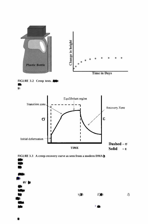
40 DN7036138Issue 3-2
BSS09006: GPRS System Feature Description
Id:0900d8058077eafd
System impact of GPRS
• 3028 NETWORK SERVICE VIRTUAL CONNECTION IDENTIFIER UNKNOWN • 3029 BSSGP VIRTUAL CONNECTION UNBLOCK PROCEDURE FAILED • 3030 BSSGP VIRTUAL CONNECTION BLOCK PROCEDURE FAILED • 3031 BSSGP VIRTUAL CONNECTION RESET PROCEDURE FAILED • 3032 BSSGP VIRTUAL CONNECTION PROTOCOL ERROR • 3033 UNKNOWN ROUTING AREA OR LOCATION AREA DURING PAGING • 3068 EGPRS DYNAMIC ABIS POOL FAILURE • 3073 FAULTY PCUPCM TIMESLOTS IN PCU • 3164 PCU PROCESSOR OVERLOAD ALARM • 3209 SUB NETWORK SERVICE SIZE PROCEDURE FAILED • 3210 SUB NETWORK SERVICE CONFIGURATION PROCEDURE FAILED • 3211 LAST REMOTE IP DATA ENDPOINT DELETED • 3261 FAILURE IN UPDATING BSC SPECIFIC PARAMETERS TO PCU • 3273 GPRS/EDGE TERRITORY FAILURE • 3324 FAILURE IN UPDATING CONFIGURATION DATA TO PCU • 7724 CONFLICT BETWEEN BSS RADIO NETWORK DATABASE AND CALL
CONTROL • 7725 TRAFFIC CHANNEL ACTIVATION FAILURE • 7730 CONFIGURATION OF BCF FAILED • 7738 BTS WITH NO TRANSACTIONS • 7769 FAILURE IN UPDATING CELL SPECIFIC PARAMETERS TO PCU • 7789 NO (E)GPRS TRANSACTIONS IN BTS
For more information on alarms, see Notices (0-999), Failure Printouts (2000-3999) and Base Station Alarms (7000-7999).
3.5.5 Measurements and countersThe following measurements are related to GPRS:
• 72 Packet Control Unit Measurement • 73 RLC Blocks per TRX Measurement • 74 Frame Relay Measurement • 76 Dynamic Abis Measurement
• For counters of 76 Dynamic Abis Measurement, see System impact of Dynamic Abis.
• 79 Coding Scheme Measurement • 90 Quality of Service Measurement • 95 GPRS Cell Re-selection Measurement
• For counters of 95 GPRS Cell Re-selection Measurement, see System impact of Network Controlled Re-selection.
• 96 GPRS RX Level and Quality Measurement • 98 Gb Over IP Measurement
• For counters of 98 Gb over IP Measurement, see System impact of Gb over IP. • 105 PS DTM Measurement
• For counters of 105 PS DTM Measurement, see System impact of Dual Transfer Mode.
• 106 CS DTM Measurement

DN7036138Issue 3-2
41
BSS09006: GPRS System Feature Description System impact of GPRS
Id:0900d8058077eafd
• For counters of 106 CS DTM Measurement, see System impact of Dual Transfer Mode.
• 110 PCU Utilisation Measurement
72 Packet Control Unit Measurement
For more information, see 72 Packet Control Unit Measurement.
73 RLC Blocks per TRX Measurement
For more information, see 73 RLC Blocks per TRX Measurement.
Name Number
RLC DATA BLOCKS UL CS1 072062
RLC DATA BLOCKS DL CS1 072063
RLC DATA BLOCKS UL CS2 072064
RLC DATA BLOCKS DL CS2 072065
RETRA RLC DATA BLOCKS DL CS1 072068
RETRA RLC DATA BLOCKS DL CS2 072069
BAD FRAME IND UL CS1 072070
BAD FRAME IND UL CS2 072071
RETRA DATA BLOCKS UL CS1 072173
RETRA DATA BLOCKS UL CS2 072174
WEIGHTED DL TSL ALLOC GPRS NUMERATOR 072195
WEIGHTED DL TSL ALLOC GPRS DENOMINATOR 072196
RLC RETRANSMITTED DL CS1 DUE OTHER THAN NACK 072222
RLC RETRANSMITTED DL CS2 DUE OTHER THAN NACK 072223
DL CS1 DATA FOR DUMMY LLC 072224
IGNORED RLC DATA BLOCKS UL DUE TO BSN CS1 072225
IGNORED RLC DATA BLOCKS UL DUE TO BSN CS2 072226
1-PHASE UL GPRS TBF ESTABLISHMENT REQUESTS 072227
1-PHASE UL GPRS TBF SUCCESSFUL ESTABLISHMENTS 072229
Table 5 Counters of Packet Control Unit Measurement related to GPRS
Name Number
UR DL RLC MAC BLOCKS 073000
RETRANS DL RLC MAC BLOCKS 073001
SCHED UNUSED RADIO BLOCKS 073002
DL RLC MAC BLOCKS 073003
Table 6 Counters of RLC Blocks per TRX Measurement

42 DN7036138Issue 3-2
BSS09006: GPRS System Feature Description
Id:0900d8058077eafd
System impact of GPRS
74 Frame Relay Measurement
Name Number
FRMS WRONG CHECK SEQ ERR 074000
FRMS WRONG DLCI 074001
OTHER FRAME ERROR 074002
T391 TIMEOUT 074003
STAT MSG WRONG SEND SEQ NBR 074004
STAT MSG WRONG REC SEQ NBR 074005
BEAR CHANGED UNOPER 074006
BEAR RET OPER 074007
STAT MSG UNKNOWN PVC 074008
STAT MSG SENT TOO OFTEN 074009
TIME BEAR UNOPERATIONAL 074010
DLCI 1 ID 074011
DLCI 1 SENT FRMS 074012
DLCI 1 KBYTES SENT 074013
DLCI 1 REC FRMS 074014
DLCI 1 KBYTES REC FRMS 074015
DLCI 1 DISC SENT FRMS 074016
DLCI 1 BYTES DISC SENT FRMS 074017
DLCI 1 DISC REC FRMS 074018
DLCI 1 BYTES DISC REC FRMS 074019
DLCI 1 STAT ACT TO INACT 074020
DLCI 1 INACTIVITY TIME 074021
DLCI 1 DISC UL NS UDATA 074022
DLCI 5 ID 074059
DLCI 5 SENT FRMS 074060
DLCI 5 KBYTES SENT 074061
DLCI 5 REC FRMS 074062
DLCI 5 KBYTES REC FRMS 074063
DLCI 5 DISC SENT FRMS 074064
DLCI 5 BYTES DISC SENT FRMS 074065
DLCI 5 DISC REC FRMS 074066
DLCI 5 BYTES DISC REC FRMS 074067
DLCI 5 STAT ACT TO INACT 074068
DLCI 5 INACTIVITY TIME 074069
DLCI 5 DISC UL NS UDATA 074070
Table 7 Counters of Frame Relay Measurement
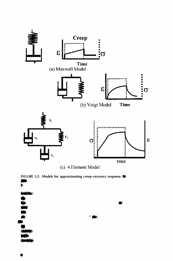
DN7036138Issue 3-2
43
BSS09006: GPRS System Feature Description System impact of GPRS
Id:0900d8058077eafd
For more information, see 74 Frame Relay Measurement.
79 Coding Scheme Measurement
DLCI 6 ID 074071
DLCI 6 SENT FRMS 074072
DLCI 6 KBYTES SENT 074073
DLCI 6 REC FRMS 074074
DLCI 6 KBYTES REC FRMS 074075
DLCI 6 DISC SENT FRMS 074076
DLCI 6 BYTES DISC SENT FRMS 074077
DLCI 6 DISC REC FRMS 074078
DLCI 6 BYTES DISC REC FRMS 074079
DLCI 6 STAT ACT TO INACT 074080
DLCI 6 INACTIVITY TIME 074081
DLCI 6 DISC UL NS UDATA 074082
: :
DLCI 16 ID 074191
DLCI 16 SENT FRMS 074192
DLCI 16 KBYTES SENT 074193
DLCI 16 REC FRMS 074194
DLCI 16 KBYTES REC FRMS 074195
DLCI 16 DISC SENT FRMS 074196
DLCI 16 BYTES DISC SENT FRMS 074197
DLCI 16 DISC REC FRMS 074198
DLCI 16 BYTES DISC REC FRMS 074199
DLCI 16 STAT ACT TO INACT 074200
DLCI 16 INACTIVITY TIME 074201
DLCI 16 DISC UL NS UDATA 074202
Name Number
NUMBER OF DL RLC BLOCKS IN ACKNOWLEDGED MODE 079000
NUMBER OF DL RLC BLOCKS IN UNACKNOWLEDGED MODE
079001
NUMBER OF UL RLC BLOCKS IN ACKNOWLEDGED MODE 079002
NUMBER OF UL RLC BLOCKS IN UNACKNOWLEDGED MODE
079003
Table 8 Counters of Coding Scheme Measurement
Name Number
Table 7 Counters of Frame Relay Measurement (Cont.)

44 DN7036138Issue 3-2
BSS09006: GPRS System Feature Description
Id:0900d8058077eafd
System impact of GPRS
For more information, see 79 Coding Scheme Measurement.
90 Quality of Service Measurement
For more information, see 90 Quality of Service Measurement.
96 GPRS RX Level and Quality Measurement
NUMBER OF BAD RLC DATA BLOCKS WITH VALID HEADER UL UNACK MODE
079004
NUMBER OF BAD RLC DATA BLOCKS WITH BAD HEADER UL UNACK MODE
079005
NUMBER OF BAD RLC DATA BLOCKS WITH VALID HEADER UL ACK MODE
079006
NUMBER OF BAD RLC DATA BLOCKS WITH BAD HEADER UL ACK MODE
079007
RETRANSMITTED RLC DATA BLOCKS UL 079008
RETRANSMITTED RLC DATA BLOCKS DL 079009
Name Number
NUMBER OF TBF ALLOCATIONS 090000
TOTAL NBR OF RLC BLOCKS 090001
TOTAL DURATION OF TBFS 090002
DROPPED DL LLC PDUS DUE TO OVERFLOW 090003
DROPPED DL LLC PDUS DUE TO LIFETIME EXPIRY 090004
AVERAGE MS SPECIFIC BSSGP FLOW RATE 090005
AVERAGE MS SPECIFIC BSSGP FLOW RATE DEN 090006
VWTHR NUMERATOR GPRS 090007
VWTHR DENOMINATOR GPRS 090008
Table 9 Counters of Quality of Service Measurement related to GPRS
RXL UP BOUND CLASS 0 096000
RXL UP BOUND CLASS 1 096001
RXL UP BOUND CLASS 2 096002
RXL UP BOUND CLASS 3 096003
RXL UP BOUND CLASS 4 096004
UL SAMPLES WITH RXL 0 RXQ 0 096005
UL SAMPLES WITH RXL 0 RXQ 7 096012
UL SAMPLES WITH RXL 1 RXQ 0 096013
Table 10 Counters of GPRS RX Level and Quality Measurement
Name Number
Table 8 Counters of Coding Scheme Measurement (Cont.)

DN7036138Issue 3-2
45
BSS09006: GPRS System Feature Description System impact of GPRS
Id:0900d8058077eafd
For more information, see 96 GPRS RX Level and Quality Measurement.
110 PCU Utilisation Measurement
For more information, see 110 PCU Utilisation Measurement.
3.6 Impact on Network Switching Subsystem (NSS)No impact.
UL SAMPLES WITH RXL 1 RXQ 7 096020
UL SAMPLES WITH RXL 2 RXQ 0 096021
UL SAMPLES WITH RXL 2 RXQ 7 096028
UL SAMPLES WITH RXL 3 RXQ 0 096029
UL SAMPLES WITH RXL 3 RXQ 7 096036
UL SAMPLES WITH RXL 4 RXQ 0 096037
UL SAMPLES WITH RXL 4 RXQ 7 096044
UL SAMPLES WITH RXL 5 RXQ 0 096045
UL SAMPLES WITH RXL 5 RXQ 7 096052
DL SAMPLES WITH RXL 0 RXQ 0 096053
DL SAMPLES WITH RXL 0 RXQ 7 096060
DL SAMPLES WITH RXL 1 RXQ 0 096061
DL SAMPLES WITH RXL 1 RXQ 7 096068
DL SAMPLES WITH RXL 2 RXQ 0 096069
DL SAMPLES WITH RXL 2 RXQ 7 096076
DL SAMPLES WITH RXL 3 RXQ 0 096077
DL SAMPLES WITH RXL 3 RXQ 7 096084
DL SAMPLES WITH RXL 4 RXQ 0 096085
DL SAMPLES WITH RXL 4 RXQ 7 096092
DL SAMPLES WITH RXL 5 RXQ 0 096093
DL SAMPLES WITH RXL 5 RXQ 7 096100
PEAK RESERVED PCUPCM CHANNELS 110000
PEAK OCCUPIED PDTCH UL 110001
PEAK OCCUPIED PDTCH DL 110002
Table 11 Counters of PCU Utilization Measurement
Table 10 Counters of GPRS RX Level and Quality Measurement (Cont.)
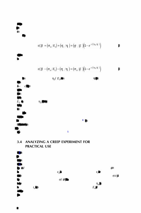
46 DN7036138Issue 3-2
BSS09006: GPRS System Feature Description
Id:0900d8058077eafd
System impact of GPRS
3.7 Impact on NetAct productsNetAct ReporterNetAct reporter can be used to view reports from measurements related to GPRS. For a list of the measurements, see Measurements and counters.
NetAct MonitorNetAct Monitor can be used to monitor all alarms related to GPRS. For a list of the alarms, see Alarms.
NetAct TracingNetAct Tracing supports GPRS-capable Nokia Siemens Network network elements in OSS3.1 ED2. Data Tracing must be supported by the BSS and the Packet Core Network.
NetAct AdministratorStandard NetAct Administration applications, such as Network Editor, Time Manage-ment, User Group Profiles, Authority Manager, and Service Access Control are used to administer GPRS.
NetAct OptimizerNo impact.
NetAct PlannerGPRS has no direct impact on NetAct Planner. However, GPRS can be taken into con-sideration when network traffic is planned and simulated with NetAct Planner.
NetAct ConfiguratorNetAct Configurator can be used to configure the radio network parameters related to GPRS. For more information, see BSS RNW Parameters and Implementing Parameter Plans in NetAct Product Documentation. For a list of the radio network parameters, see BSC parameters.
3.8 Impact on mobile terminalsGPRS-capable mobile terminals are required.
GPRS defines three classes of mobile terminals:
• Class A terminals support simultaneous circuit-switched (CS) and packet-switched (PS) traffic.
• Class B terminals attach to the network as both CS and PS clients but only support traffic from one service at a time.
• Class C terminals may support both CS and PS services.
With Class C terminals, users must manually select either CS or PS mode, or the termi-nals can be set up to accept data only. Class C terminals cannot accept paging from both CS and PS at the same time. However, Class B terminals can accept paging of any type when in idle mode.
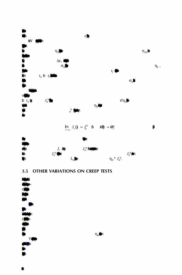
DN7036138Issue 3-2
47
BSS09006: GPRS System Feature Description System impact of GPRS
Id:0900d8058077eafd
3.9 Impact on interfacesImpact on radio interfaceNo impact.
Impact on Abis interface
• Dynamic AbisDynamic Abis pools need to be configured for GPRS if CS-3 & CS-4 is in use.
• GPRS messagesThe Abis interface supports GPRS messages.
Impact on A interfaceNo impact.
Impact on Gb interfaceThe Nokia Siemens Networks BSC supports the Gb interface (BSC-SGSN) as specified in GSM Recommendations (3GPP):
• 3GPP TS 48.018, General Packet Radio Service (GPRS); Base Station System (BSS) - Serving GPRS Support Node (SGSN); BSS GPRS Protocol (BSSGP)
• 3GPP TS 48.016, General Packet Radio Service (GPRS); Base Station System (BSS) - Serving GPRS Support Node (SGSN) interface; Network Service
Impact on Gs interfaceNokia Siemens Networks SGSN and MSC support the Gs interface (SGSN-MSC/VLR) although it is specified as optional by 3GPP.
The advantages of Gs interface include:
• support for TIA/EIA-136 networks by offering a connection for the tunneling of non-GSM signalling messages via the GPRS network to a non-GSM MSC/VLR.
• more effective radio resource usage with combined GPRS/IMSI attach/detach and combined RA/LA updates, that is, reduced signalling over the radio interface.
• the possibility to page GPRS terminals for circuit-switched services (for example circuit-switched calls) via GPRS.
3.10 Interworking with other featuresThe implementation of GPRS causes changes to the following existing functions of the BSC:
• the PCU plug-in unit is introduced in Hardware Configuration Management • GPRS-related radio network parameters are introduced in Radio Network Configu-
ration Management • co-operation between circuit-switched traffic and GPRS traffic is defined in Radio
Channel Allocation • GPRS traffic is monitored with GPRS-specific measurements and counters • the serving PCU must be the same for all TRXs under one segment.
For more information on the implementation procedure, see:
• Implementing GPRS overview • Radio network management for GPRS
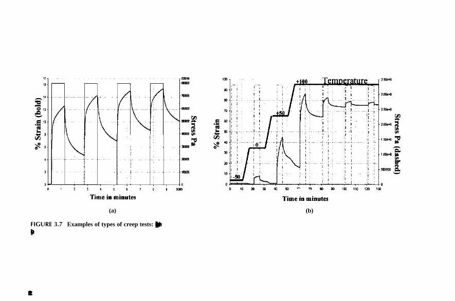
48 DN7036138Issue 3-2
BSS09006: GPRS System Feature Description
Id:0900d8058077eafd
System impact of GPRS
• Gb interface configuration and state management • Radio resource management • GPRS/EDGE radio connection control
The GPRS related measurements are introduced in section Measurements and coun-ters.
Circuit-switched trafficIn the BSC the introduction of GPRS means dividing the radio resources (circuit-switched and GPRS traffic) into two territories. This has an effect on the radio channel allocation features in which the BSC makes decisions based on the load of traffic. For some features only the resources of the circuit-switched territory are included in the decisions. However, for most features also the traffic channels in the GPRS territory need to be taken into consideration when the BSC defines the traffic load, because radio timeslots (RTSL) in the GPRS territory may be allocated for circuit-switched traffic if nec-essary. Only if there are radio timeslots that are permanently reserved for GPRS use (dedicated GPRS resources), these cannot be used for circuit-switched calls and the BSC excludes these in its decisions on traffic load.
Frequency HoppingIn Baseband hopping, radio timeslot 0 belongs to a different hopping group than the other radio timeslots of a TRX. This makes radio timeslot 0 unusable for multislot con-nections. If Baseband hopping is employed in a BTS, radio timeslot 0 of any TRX in the BTS is not used for GPRS.
Optimisation of MS Power LevelThe BSC attempts to allocate traffic channels within the circuit-switched territory accord-ing to the interference level recommendation the BSC has calculated, to allow the per-forming of optimisation of the MS power level. When the BSC has to allocate a traffic channel for a circuit-switched request in the GPRS territory, the interference level rec-ommendation is no longer the guiding factor. Now, the first GPRS radio timeslot next to the territory border is taken regardless of whether its interference level is among the rec-ommended ones or not. For more information on the division of territories, see section Radio resource management.
Intelligent Underlay-Overlay, Enhanced Coverage by Frequency Hopping, Handover Support for Coverage EnhancementsSuper-reuse TRX frequencies are not supported for GPRS.
Dynamic SDCCH allocation The BSC selects a traffic channel timeslot to be reconfigured as a dynamic SDCCH timeslot always within the circuit-switched territory.
TRX prioritisation in TCH allocationThe operator can set the BCCH TRX or the non-BCCH TRXs as preferred TRX for the GPRS territory with the parameter prefer BCCH frequency GPRS (BFG). If no pref-erence is indicated, no prioritisation is used between the different TRX types when the GPRS territory is formed.
Trunk ReservationIn trunk reservation, the BSC defines the number of idle traffic channels. The BSC adds together the number of idle traffic channels in the circuit-switched territory and the

DN7036138Issue 3-2
49
BSS09006: GPRS System Feature Description System impact of GPRS
Id:0900d8058077eafd
number of traffic channels in the radio timeslots of the GPRS territory. The traffic channels in the radio timeslots that the BSC has allocated permanently for GPRS, are excluded.
TRX faultWhen a TRX carrying traffic channels becomes faulty, the radio timeslots on the TRX are blocked from use. The BSC releases the ongoing calls and the call control resources. The BSC downgrades the traffic channels belonging to the GPRS territory in the faulty TRX from GPRS use. To replace the lost GPRS capacity, the BSC determines the possibility of a GPRS territory upgrade in another TRX. For more information on GPRS territory upgrades and downgrades, see section Radio resource management.
If the faulty TRX functionality is reconfigured to another TRX in the cell, the value of the GPRS enabled TRX (GTRX) parameter is also transferred to the new TRX.
If the faulty TRX is EDGE-capable, and GPRS in enabled in the TRX and CS-3 & CS-4 or EGPRS is enabled in the BTS, the system tries to reconfigure its functionality to another EDGE-capable TRX in the BTS.
Resource indication to MSCIn general, the BSC’s indication on the resources concerns traffic channels of a BTS excluding those allocated permanently to GPRS (dedicated GPRS channels). GPRS territory resources other than the dedicated ones are regarded as working and idle resources.
Half RatePermanent type half rate timeslots are not used for GPRS traffic. Therefore, it is recom-mended not to configure permanent half rate timeslots in TRXs that are planned to be used for GPRS.
When the BSC can select the channel rate (full rate or half rate) to be used for a circuit-switched call based on the traffic load of the target BTS, the load limits used in the pro-cedure are calculated using the operator defined BSC and BTS parameters lower limit for HR TCH resources (HRL), upper limit for HR TCH resources (HRU), lower limit for FR TCH resources (FRL), and upper limit for FR TCH resources (FRU). The BSC parameter CS TCH allocation calculation (CTC) defines how the GPRS territory is seen when the load limits are calculated. Depending on the value of CTC either only CS territory or both CS and GPRS territories (excluding the dedicated GPRS timeslots) are used to calculate the load limits. Additionally, with the CTC parameter the user can define whether the resources in GPRS territory are seen as idle resources or as occupied resources.
High Speed circuit-switched Data (HSCSD)If GPRS has been enabled in a BTS, the HSCSD-related load limits are calculated based on the existing HSCSD parameters and the following rules:
• the number of working resources includes all the working full rate traffic channel (TCH/F) resources of a BTS, excluding the ones that have been allocated perma-nently to GPRS
• the number of occupied TCH/F resources includes all the occupied TCH/Fs of the circuit-switched territory, as well as the default GPRS territory TCH/Fs, excluding the GPRS radio timeslots defined as dedicated

50 DN7036138Issue 3-2
BSS09006: GPRS System Feature Description
Id:0900d8058077eafd
System impact of GPRS
• HSCSD parameter HSCSD cell load upper limit (HCU) is replaced with the radio network GPRS parameter free TSL for CS downgrade (CSD) if the latter is more restricting; thus the one that limits HSCSD traffic earlier is used.
The parameter free TSL for CS downgrade (CSD) defines a margin of radio timeslots that the BSC tries to keep idle for circuit-switched traffic by downgrading the GPRS territory when necessary.
If HSCSD multislot allocation is denied based on the appropriate parameters, the BSC rejects the transparent HSCSD requests and serves the non-transparent HSCSD requests with one timeslot.
If the timeslot share in HSCSD allocation is not restricted, the transparent requests are served preferably in the circuit-switched territory, and only if necessary in the GPRS ter-ritory. If a transparent HSCSD call ends up in the GPRS territory, the BSC does not try to move it elsewhere with an intra cell handover. Instead, it tries to replace the lost GPRS capacity by extending the GPRS territory on the circuit-switched side of the ter-ritory border.
When the transparent HSCSD call inside the GPRS territory is later released, the BSC returns the released radio timeslots back to GPRS use to keep the GPRS territory con-tinuous and undivided. For more information on how the resources form the territories, see section Radio resource management.
The non-transparent HSCSD requests are always served in the circuit-switched territory as long as there is at least one TCH/F available. A normal HSCSD upgrade procedure is applied later to fulfill the need of the non-transparent request, if the call starts with less channels than needed and allowed. In order for the non-transparent call to get the needed number of timeslots, the BSC starts an intra cell handover for suitable single slot calls beside the non-transparent HSCSD call. At the start of the handover, the BSC checks that a single slot call can be moved to another radio timeslot and that an HSCSD upgrade is generally allowed.
A non-transparent HSCSD call enters the GPRS territory only if there is congestion in the circuit-switched territory. If multislot allocation was originally defined as allowed, it is also applied within the GPRS territory to serve the non-transparent request. If the BTS load later decreases, enabling a GPRS territory upgrade, the non-transparent HSCSD call is handed over to another location in the BTS so that the GPRS territory can be extended.
When deciding whether to downgrade an HSCSD call or the GPRS territory, the BSC checks first if the margin of idle resources defined by the parameter free TSL for CS downgrade (CSD) exists. If a sufficient margin exists, the BSC acts as without GPRS, that is, using the state information that the HSCSD parameters define for the BTS, the BSC performs an HSCSD downgrade if necessary. If the number of idle resources is below the parameter free TSL for CS downgrade (CSD), the actions proceed as follows:
• if there are GPRS radio timeslots that are above and beyond the operator defined default GPRS territory then these additional GPRS radio timeslots are the first target for the GPRS territory downgrade
• if there are no additional GPRS radio timeslots, the BSC examines if there are more HSCSD traffic channels than the parameter HSCSD TCH capacity minimum (HTM) requires and if so, executes an HSCSD downgrade

DN7036138Issue 3-2
51
BSS09006: GPRS System Feature Description System impact of GPRS
Id:0900d8058077eafd
• if the minimum HSCSD capacity is not in use, a GPRS territory downgrade is made to maintain the margin defined by the parameter free TSL for CS downgrade (CSD).
As a TCH/F becomes free through a channel release, the BSC first examines the need and possibility for an HSCSD upgrade. If the BSC starts no HSCSD upgrade, it further checks the need and possibility for a GPRS upgrade. The GPRS territory can be upgraded although the parameter HSCSD TCH capacity minimum (HTM) is not in use and there are pending HSCSD connections in the cell. The parameter free TSL for CS upgrade (CSU) and the margin it defines is the limiting factor for a GPRS territory upgrade.
Parameter free TSL for CS upgrade (CSU) defines the number of radio timeslots that have to remain idle in the circuit-switched territory after the planned GPRS territory upgrade has been performed.
For more information on GPRS territories, see section Radio resource management, and for more information on HSCSD, see HSCSD and 14.4 kbit/s Data Services in BSC.
Radio Network Supervision Actions of the radio network supervision do not apply for timeslots that have been included in the GPRS territory. The only reasonable thing to monitor is the uplink inter-ference on timeslots in GPRS use.
Radio Network Supervision does not apply to the packet control channel.
BTS testingBTS testing cannot be executed on the packet control channel.
Multi BCF Control, Common BCCH ControlMulti BCF introduces a radio network object called the segment. Several BTS objects can belong to one segment. Only one BTS object of the segment can have a BCCH. The segment can have BTS objects, which differ in:
• frequency band (GSM800, PGSM900, EGSM900, GSM1800, and GSM1900) • power levels (Talk-family and UltraSite base stations) • regular and super-reuse frequencies • EDGE capability.
TRXs inside a BTS object must have common capabilities. An exception to this is that EDGE-capable and non-EDGE-capable TRXs can be configured to the same BTS object. When EGPRS or CS-3 & CS-4 is enabled in the BTS, there exist some restric-tions related to TRX configuration. For more information, see section Resrictions. PS territory can be defined to each BTS object separately. GPRS and EGPRS territories cannot both be defined to a BTS object at the same time. Super-reuse frequencies are not supported in GPRS.
For information on restrictions when baseband hopping is used, see EDGE BTSs and hopping in System impact of EDGE in EDGE System Feature Description.
There is only one BCCH /CCCH in one segment.
You must define GPRS territory to the BCCH frequency band in a Common BCCH cell in which more than one frequency band is in use. Otherwise GPRS does not work properly in the cell. The reason for this requirement is that in cases when the MS RAC of the GPRS mobile is not known by the BSC, the temporary block flow (TBF) must be allocated on the BCCH frequency band first. During the first TBF allocation, the GPRS
52 DN7036138Issue 3-2
BSS09006: GPRS System Feature Description
Id:0900d8058077eafd
System impact of GPRS
mobile indicates its frequency capability to the BSC. After that, other frequency bands of the cell can be used for the GPRS mobile accordingly.
GPRS territory must be configured into the BCCH BTS of a segment with two or more BTSs on the BCCH band if BTS(s) containing GPRS channels are hopping.
This is because hopping frequency parameters are encoded to the IMMEDIATE ASSIGNMENT message on CCCH with indirect encoding. When the allocated BTS is hopping, indirect encoding can only refer to the SYSTEM INFORMATION TYPE 13 message, which in the Nokia Siemens Networks BSS contains GPRS Mobile Allocation only for the BCCH BTS.
The limitation to use only indirect encoding with hopping frequency parameters in IMMEDIATE ASSIGNMENT comes from the fact that IMMEDIATE ASSIGNMENT message segmentation is not supported in the BSS. The other two possible hopping fre-quency encodings, direct 1 and 2, might use a large number of octets for the frequency hopping. Large sized frequency parameters cause control message segmentation. Thus as IMMEDIATE ASSIGNMENT segmentation is not supported, direct 1 and 2 encoding cannot be used.
Therefore, in a segment where BCCH band GPRS channels are on hopping BTS(s), the TBFs must initially be allocated to the BCCH BTS. Later, the TBFs may be reallocated to other BTSs as well.
See Common BCCH Control and Multi BCF Control for more information on Multi BCF and Common BCCH.
Dual Transfer ModeGPRS must be available and active in the network for Dual Transfer Mode (DTM) to work. The BSC supports DTM data transfer in both GPRS and EGPRS modes. If GPRS is deactivated when DTM is in use, the MSS that have an active DTM connection keep their CS connection but lose their TBFs. A DTM TBF is established in EGPRS mode if the MS is EGPRS capable and if the DTM call is allocated from an EGPRS-capable PS territory. If not, the DTM TBF is established in GPRS mode.
For more information on DTM, see Dual Transfer Mode.
EGSM 900 - PGSM 900 BTSWhen the BCCH is on PGSM 900 frequency band in the PGSM-EGSM BTS and RF hopping is used, GPRS has to be disabled in the RF hopping TRXs. Set the GPRS enabled TRX (GTRX) parameter of the RF hopping TRXs to value 'N'.
The following restrictions apply when there are EGSM 900 and PGSM 900 frequencies in the BTS and GPRS/EDGE Support for PGSM-EGSM BTS is not used:
• When BCCH is on EGSM 900 frequency band and there is a TRX on PGSM 900 frequency band in the BTS, GPRS/EDGE cannot be used in the PGSM 900 TRXs in the BTS. Set the GPRS enabled TRX (GTRX) parameter of the PGSM 900 TRXs to value 'N'.
• When BCCH is on PGSM 900 frequency band and there is a TRX on EGSM 900 frequency band in the BTS, GPRS/EDGE cannot be used in the EGSM 900 TRXs in the BTS. Set the GPRS enabled TRX (GTRX) parameter of the EGSM 900 TRXs to value 'N'.

DN7036138Issue 3-2
53
BSS09006: GPRS System Feature Description System impact of GPRS
Id:0900d8058077eafd
BSS21238 “Merged P-&E-GSM900”If the feature BSS21238 “Merged P-&E-GSM900” is activated in the cell, GPRS is allowed to be used in RF hopping TRXs even if the BCCH is on PGSM 900 frequency band in the PGSM-EGSM BTS.
Extended Cell RangeGPRS/EDGE cannot be used in Extended TRXs (E-TRX) without extended cell GPRS/EDGE channels (EGTCH).
Extended Cell for GPRS/EDGEWith GPRS/EDGE and Extended Cell for GPRS/EDGE application software products GPRS/EDGE traffic can be used in EGTCH channels of Extended TRXs (E-TRX). EGTCHs constitutes of fixed PS channels and they cannot be used for CS traffic.
Dynamic Frequency and Channel AllocationGPRS/EDGE can be used in DFCA TRXs, if BSS21161: SDCCH and PS Data Channels on DFCA TRX is active.
For more information, see:
• Activating and Testing BSS21161: SDCCH and PS Data Channels on DFCA TRX • BSS21161: SDCCH and PS Data Channels on DFCA TRX

54 DN7036138Issue 3-2
BSS09006: GPRS System Feature Description
Id:0900d80580783c54
System impact of GPRS related software
4 System impact of GPRS related software
4.1 System impact of Extended Uplink TBF ModeThe system impact of BSS11151: Extended Uplink TBF Mode is specified in the sections below. For an overview, see Extended Uplink TBF Mode.
For implementation instructions, see Activating and Testing BSS11151: Extended Uplink TBF Mode.
Extended Uplink TBF Mode requires GPRS as a prerequisite.
4.1.1 Requirements
Hardware requirements
Software requirements
Frequency band supportThe BSC supports Extended Uplink TBF Mode on the following frequency bands:
• GSM 800
Network element Hardware/firmware required
BSC No requirements
BTS No requirements
TCSM No requirements
SGSN No requirements
Table 12 Required additional or alternative hardware or firmware.
Network element Software release required
BSC S13
BTSplus BTSs No requirements
Flexi Multiradio BTSs
No requirements
Flexi EDGE BTSs No requirements
UltraSite BTSs No requirements
MetroSite BTSs No requirements
Talk-family BTSs No requirements
MSC/HLR No requirements
SGSN No requirements
NetAct OSS4.2 CD Set 1
Table 13 Required software
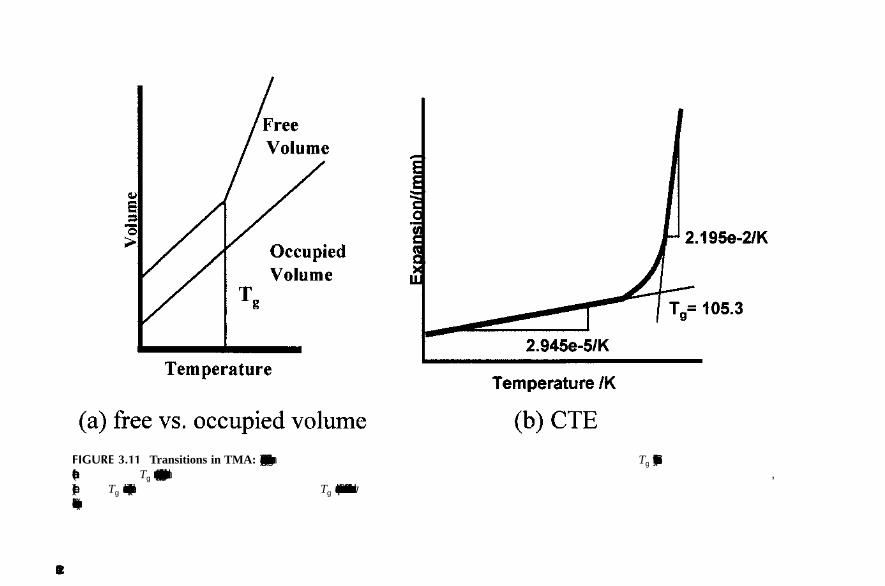
DN7036138Issue 3-2
55
BSS09006: GPRS System Feature Description System impact of GPRS related software
Id:0900d80580783c54
• GSM 900 • GSM 1800 • GSM 1900
4.1.2 Impact on transmissionNo impact.
4.1.3 Impact on BSS performance
OMU signallingNo impact.
TRX signallingNo impact.
Impact on BSC units
Impact on BTS unitsNo impact.
4.1.4 User interface
BSC MMIThe following command groups and MML commands are used to handle Extended Uplink TBF Mode:
• Parameter Handling: WOA, WOI, WOC • Base Transceiver Station Handling in BSC: EQV
For more information on the command groups and commands, see the respective MML commands manuals.
BTS MMIExtended Uplink TBF Mode cannot be managed with BTS MMI.
BSC parametersPRFILE parameters
• UL_TBF_REL_DELAY_EXT
• UL_TBF_SCHED_RATE_EXT
BSC unit Impact
OMU No impact.
MCMU No impact.
BCSU No impact.
PCU Faster uplink data flow continuing after short breaks.
Table 14 Impact of Extended Uplink TBF Mode on BSC units

56 DN7036138Issue 3-2
BSS09006: GPRS System Feature Description
Id:0900d80580783c54
System impact of GPRS related software
• POLLING_INTERVAL_STRM • POLLING_INTERVAL_IA • POLLING_INTERVAL_BG
• POLLING_INTERVAL_STR_LOW
• POLLING_INTERVAL_IA_LOW • POLLING_INTERVAL_BG_LOW
For more information on PRFILE parameters, see PRFILE and FIFILE Parameter List.
AlarmsNo alarms are specifically related to Extended Uplink TBF Mode.
Measurements and countersThe following measurements and counters are related to Extended Uplink TBF Mode.
72 Packet Control Unit Measurement
The counters are collected on BTS level.
For more information, see 72 Packet Control Unit Measurement.
4.1.5 Impact on Network Switching Subsystem (NSS)No impact.
4.1.6 Impact on NetAct products
NetAct AdministratorNo impact.
NetAct MonitorNo impact.
NetAct OptimizerNo impact.
NetAct PlannerNo impact.
NetAct ConfiguratorNo impact.
NetAct ReporterNetAct reporter can be used to create reports from measurements related to Extended Uplink TBF Mode. For a list of the measurements, see Measurements and counters.
Name Number
UL DATA CONT AFTER COUNTDOWN 072115
EXTENDED UL TBFS 072116
Table 15 Counters of 72 Packet Control Unit Measurement

DN7036138Issue 3-2
57
BSS09006: GPRS System Feature Description System impact of GPRS related software
Id:0900d80580783c54
NetAct TracingNo impact.
4.1.7 Impact on mobile terminals3GPP Rel.4 GERAN feature package 1 MS required.
4.1.8 Impact on interfaces
Impact on radio interfaceNo impact.
Impact on Abis interfaceSupport for Extended UL TBF Mode related signalling with the MS.
Impact on A interfaceNo impact.
Impact on Gb interfaceNo impact.
4.1.9 Interworking with other featuresNo impact.

58 DN7036138Issue 3-2
BSS09006: GPRS System Feature Description
Id:0900d8058077eb5c
4.2 System impact of Priority Class based Quality of ServiceThe system impact of BSS10084: Priority Class based Quality of Service is specified in the sections below. For an overview, see Priority Class based Quality of Service.
4.2.1 Requirements
Hardware requirements
Software requirements
Frequency band supportThe BSC supports Priority Class based Quality of Service on the following frequency bands:
• GSM 800 • GSM 900 • GSM 1800
Network element Required hardware or firmware
BSC PCU1/PCU2
BTS No requirements
TCSM No requirements
SGSN No requirements
Table 16 Required additional or alternative hardware or firmware
Network element Software release required
BSC S13
BTSplus BTSs No requirements
Flexi Multiradio BTSs
No requirements
Flexi EDGE BTSs No requirements
UltraSite EDGE BTSs
No requirements
MetroSite EDGE BTSs
No requirements
Talk-family BTSs No requirements
MSC/HLR M14
GGSN GGSN2
CG2/3
SGSN SG7
NetAct OSS4.2 CD Set 1
Table 17 Required software

DN7036138Issue 3-2
59
BSS09006: GPRS System Feature Description
Id:0900d8058077eb5c
• GSM 1900
4.2.2 Impact on transmissionNo impact.
4.2.3 Impact on BSS performance
OMU signallingNo impact.
TRX signallingNo impact.
Impact on BSC units
Impact on BTS unitsNo impact.
4.2.4 User interface
BSC MMIThe following command group and MML commands are used to handle Priority Class based Quality of Service:
• Base Station Controller Parameter Handling in BSC: EEV, EEO
BTS MMIPriority Class based Quality of Service cannot be managed with BTS MMI.
BSC parametersBSC radio network parameters
There are different radio network parameters for priority based scheduling in PCU1 and PCU2. Table Radio network parameters for Priority Based Scheduling describes the correspondence of these parameters between PCU1 and PCU2.
The following parameters apply to PCU1:
• DL high priority SSS (DHP)
• DL normal priority SSS (DNP) • DL low priority SSS (DLP)
BSC unit Impact
OMU No impact
MCMU No impact
BCSU No impact
PCU Both PCU1 and PCU2 support Priority Class based Quality of Service.
Table 18 Impact of Priority Class based Quality of Service on BSC units

60 DN7036138Issue 3-2
BSS09006: GPRS System Feature Description
Id:0900d8058077eb5c
• UL priority 1 SSS (UP1) • UL priority 2 SSS (UP2)
• UL priority 3 SSS (UP3) • UL priority 4 SSS (UP4)
The following parameters apply to PCU2:
• background traffic class scheduling weight for ARP 1 (BGSW1)
• background traffic class scheduling weight for ARP 2 (BGSW2) • background traffic class scheduling weight for ARP 3 (BGSW3)
• interactive 1 traffic class scheduling weight for ARP 1 (ISW11) • interactive 1 traffic class scheduling weight for ARP 2 (ISW12)
• interactive 1 traffic class scheduling weight for ARP 3 (ISW13) • interactive 2 traffic class scheduling weight for ARP 1 (ISW21)
• interactive 2 traffic class scheduling weight for ARP 2 (ISW22)
• interactive 2 traffic class scheduling weight for ARP 3 (ISW23 • interactive 3 traffic class scheduling weight for ARP 1 (ISW31)
• interactive 3 traffic class scheduling weight for ARP 2 (ISW32)
• interactive 3 traffic class scheduling weight for ARP 3 (ISW33)
• streaming traffic class scheduling weight for ARP 1 (SSW1) • streaming traffic class scheduling weight for ARP 2 (SSW2)
• streaming traffic class scheduling weight for ARP 3 (SSW3)
For more information on radio network parameters, see BSS Radio Network Parameter Dictionary.
AlarmsNo impact.
Scheduling step size (PCU1)
Scheduling weight (PCU2)
1 60
2 30
3 20
4 15
5 12
6 10
7 9
8 8
9 7
10 6
11 5
12 5
Table 19 Radio network parameters for Priority Based Scheduling
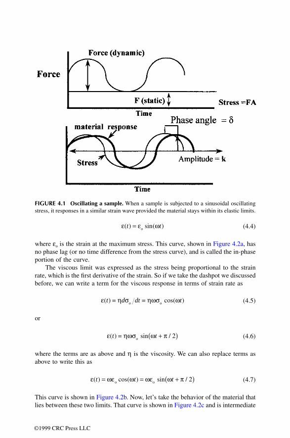
DN7036138Issue 3-2
61
BSS09006: GPRS System Feature Description
Id:0900d8058077eb5c
Measurements and countersThe following measurement and counters are related to Priority Class based Quality of Service:
90 Quality of Service Measurement
For more information, see 90 Quality of Service Measurement.
4.2.5 Impact on Network Switching Subsystem (NSS)The subscriber priority must be defined in the DX HLR (HLR) once Priority Class based Quality of Service is introduced in the network.
4.2.6 Impact on NetAct products
NetAct AdministratorNo impact.
NetAct MonitorNo impact.
NetAct OptimizerTRECs are supported in Service Optimizer (OSS3.1).
Name Number
NUMBER OF TBF ALLOCATIONS 090000
TOTAL NBR OF RLC BLOCKS 090001
TOTAL DURATION OF TBFS 090002
DROPPED DL LLC PDUS DUE TO OVERFLOW
090003
DROPPED DL LLC PDUS DUE TO LIFETIME EXPIRY
090004
AVERAGE MS SPECIFIC BSSGP FLOW RATE
090005
AVERAGE MS SPECIFIC BSSGP FLOW RATE DEN
090006
VWTHR NUMERATOR GPRS 090007
VWTHR DENOMINATOR GPRS 090008
VWTHR NUMERATOR EDGE OTHER 4 090009
VWTHR DENOMINATOR EDGE OTHER 4
090010
VWTHR NUMERATOR EDGE 4 090011
VWTHR DENOMINATOR EDGE 4 090012
Table 20 Counters of Quality of Service Measurement
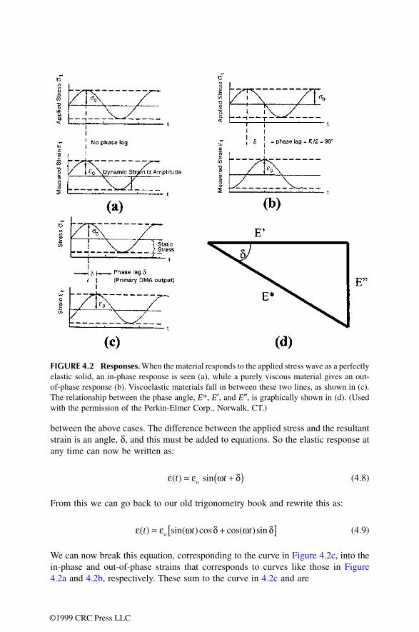
62 DN7036138Issue 3-2
BSS09006: GPRS System Feature Description
Id:0900d8058077eb5c
NetAct PlannerPriority Class based Quality of Service is supported in NetAct Planner. The precedence class and traffic class can be set for packet switched services.
NetAct ConfiguratorConfigurator can be used to configure the radio network parameters related to Priority Class based Quality of Service. For more information, see BSS RNW Parameters and Implementing Parameter Plans in NetAct Product Documentation. For a list of the radio network parameters, see BSC parameters.
NetAct ReporterNetAct Reporter can be used to view and create reports based on measurements related to Priority Class based Quality of Service. For a list of the measurements, see Measurements and counters.
NetAct TracingThe Quality of Service type is shown in the GPRS trace report in NetAct Tracing.
4.2.7 Impact on mobile terminalsGPRS/EDGE-capable mobile terminals are required.
4.2.8 Impact on interfaces
Impact on radio interfaceSee Priority Class based Quality of Service for details.
Impact on Abis interfaceNo impact.
Impact on A interfaceNo impact.
Impact on Gb interfaceNo impact.
4.2.9 Interworking with other features
PCU and Priority Class based Quality of ServicePriority Class based Quality of Service works with both PCU1 and PCU2. There is an efficient Quality of Service differentiation mechanism in Priority Class based Quality of Service with PCU1. The differentiation is implemented by tuning the scheduling step size parameters (SSS). These parameters correspond to the scheduling weight param-eters with PCU2. The SSS parameters cannot be used with PCU2.

DN7036138Issue 3-2
63
BSS09006: GPRS System Feature Description
Id:0900d80580782d2d
4.3 System impact of System Level TraceThe system impact of BSS10089: System Level Trace is specified in the sections below. For an overview, see System Level Trace.
4.3.1 Requirements
Hardware requirements
Software requirements
Frequency band supportThe BSC supports System Level Trace on the following frequency bands:
• GSM 800 • GSM 900 • GSM 1800 • GSM 1900
Network element Hardware/firmware required
BSC No requirements
BTS No requirements
TCSM No requirements
SGSN No requirements
Table 21 Required additional or alternative hardware or firmware
Network element Software release required
BSC S13
BTSplus No requirements
Flexi Multiradio BTSs
No requirements
Flexi EDGE BTSs No requirements
UltraSite EDGE BTSs
No requirements
MetroSite EDGE BTSs
No requirements
Talk-family BTSs No requirements
MSC/HLR M14
GGSN GGSN2
SGSN SG7
NetAct OSS4.2 CD Set 1
Table 22 Required software

64 DN7036138Issue 3-2
BSS09006: GPRS System Feature Description
Id:0900d80580782d2d
4.3.2 Impact on transmissionNo impact.
4.3.3 Impact on BSS performance
OMU signallingNo impact.
TRX signallingNo impact.
Impact on BSC
Impact on BTS unitsNo impact.
4.3.4 User interface
BSC MMINo impact.
BTS MMISystem Level Trace cannot be managed with BTS MMI.
BSC parametersNo impact.
AlarmsNo impact.
Measurements and countersThe following observations and counters are related to System Level Trace.
25 TBF Observation for GPRS Trace
BSC unit Impact
OMU No impact
MCMU No impact
BCSU No impact
PCU Faster uplink data flow continuing after short breaks.
Table 23 Impact of System Level Trace on BSC units
Name Number
SEGMENT ID 025000
Table 24 Counters of TBF Observation for GPRS Trace

DN7036138Issue 3-2
65
BSS09006: GPRS System Feature Description
Id:0900d80580782d2d
BTS ID 025001
TRX ID 025002
IMSI 025003
TBF ALLOCATION TIME 025004
TBF ALLOCATION CALENDAR TIME 025005
TBF RELEASE TIME 025006
TBF DIRECTION 025007
QOS PRIORITY CLASS 025008
NBR OF FLOW CNTRL CHANGES 025009
FLOW CTRL CHANGE TIME 0 025010
BUCKET SIZE 0 025011
QOS LEAK RATE 0 025012
... ...
FLOW CTRL CHANGE TIME 19 025067
BUCKET SIZE 19 025068
QOS LEAK RATE 19 025069
NBR OF TCHS IN BEG 025070
NBR OF REALLOC 025071
REALLOC TIME 0 025072
REALLOC CAUSE 0 025073
BTS ID 0 025074
TRX ID 0 025075
NEW NBR OF TCHS 0 025076
... ...
REALLOC TIME 19 025167
REALLOC CAUSE 19 025168
BTS ID 19 025169
TRX ID 19 025170
NEW NBR OF TCHS 19 025171
AMOUNT OF LLC DATA 025172
NBR OF RLC BLOCKS LAST MCS 025173
INITIAL CODING SCHEME 025174
NBR OF DYNABIS MCS CHANGES 025175
MCS CHANGES 025176
MCS CHANGE TIME 0 025177
CAUSE MCS CHANGE 0 025178
Name Number
Table 24 Counters of TBF Observation for GPRS Trace (Cont.)
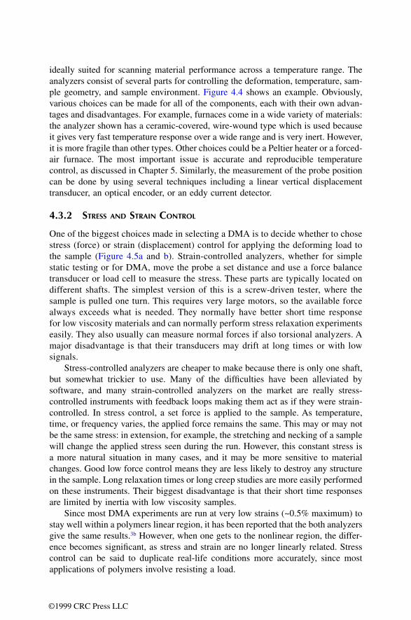
66 DN7036138Issue 3-2
BSS09006: GPRS System Feature Description
Id:0900d80580782d2d
For more information, see 25 TBF Observation for GPRS Trace.
27 GPRS Cell Re-Selection Report
NEW MCS 0 025179
NBR OF RLC BLOCKS PREV MCS 0 025180
AMOUNT OF LLC DATA PREV MCS 0 025181
... ...
MCS CHANGE TIME 19 025272
CAUSE MCS CHANGE 19 025273
NEW MCS 19 025274
NBR OF RLC BLOCKS PREV MCS 19 025275
AMOUNT OF LLC DATA PREV MCS 19 025276
CAUSE TBF RELEASE 025277
TRACE STATUS 025278
TBF DTM FLAG 025312
MULTISLOT CLASS 025313
DTM MULTISLOT CLASS 025314
Name Number
LAC CI 027000
RAC 027001
SEGMENT ID 027002
BTS ID 027003
TRX ID 027004
IMSI 027005
NC MODE 027006
CELL RESEL START TIME 027007
CELL RESEL START CAL TIME
027008
NCCR TRIGGERING CAUSE 027009
TARGET CELL ID 027010
TARGET RNC ID 027011
NACC START TIME 027012
CELL CHANGE TIME 027013
CELL RESEL END CAUSE 027014
CELL RESEL END TIME 027015
Table 25 Counters of GPRS Cell Re-Selection Report
Name Number
Table 24 Counters of TBF Observation for GPRS Trace (Cont.)

DN7036138Issue 3-2
67
BSS09006: GPRS System Feature Description
Id:0900d80580782d2d
For more information, see 27 GPRS Cell Re-Selection Report.
28 GPRS RX Level and Quality Report
For more information, see 28 GPRS RX Level and Quality Report.
Name Number
LAC CI 028000
RAC 028001
BTS ID 028002
TRX ID 028003
IMSI 028004
REP PERIOD IDLE 028005
REP PERIOD TRANSF 028006
BEP USED 028007
RECORD START TIME 028008
RECORD END TIME 028009
NR OF MEASUREMENTS 028010
UL MEAS RESULTS 1 028011
... ...
UL MEAS RESULTS 16 028026
IS PACKET TRANSF MODE 1 028027
REPORT TIME SEC AND 100TH SEC 1
028028
DL RX LEV AND QUAL 1 028029
NCELL MEAS RESULTS 1 028030
... ...
IS PACKET TRANSF MODE 16 028087
REPORT TIME SEC AND 100TH SEC 16
028088
DL RX LEV AND QUAL 16 028089
NCELL MEAS RESULTS 16 028090
NCELL INDEX 1 028091
NCELL RADIO TYPE 1 028092
NCELL ID 1 028093
... ...
NCELL INDEX 40 028208
NCELL RADIO TYPE 40 028209
NCELL ID 40 028210
Table 26 Counters of GPRS RX Level and Quality Report
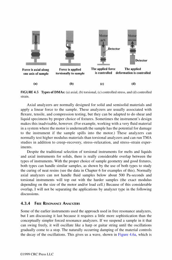
68 DN7036138Issue 3-2
BSS09006: GPRS System Feature Description
Id:0900d80580782d2d
4.3.5 Impact on Network Switching Subsystem (NSS)No impact.
4.3.6 Impact on NetAct products
NetAct AdministratorNo impact.
NetAct MonitorNo impact.
NetAct OptimizerNo impact.
NetAct PlannerNo impact.
NetAct ConfiguratorNo impact.
NetAct ReporterNetAct reporter can be used to create reports from measurements related to System Level Trace. For a list of the measurements, see Measurements and counters.
Counter value
Codec (Modulation and user data rate)
0 GPRS CS1 (GMSK 8 kbps)
1 GPRS CS2 (GMSK 12 kbps)
2 GPRS CS3 (GMSK 14.4 kbps)
3 GPRS CS4 (GMSK 20 kbps)
4 dummy value, bad header in ack mode
5 EGPRS MCS1 (GMSK 8.4 kbps)
6 EGPRS MCS2 (GMSK 11.2 kbps)
7 EGPRS MCS3 (GMSK 14.8 kbps)
8 EGPRS MCS4 (GMSK 16.8 kbps)
9 EGPRS MCS5 (8-PSK 22.5 kbps)
10 EGPRS MCS6 (8-PSK 29.6 kbps)
11 EGPRS MCS7 (8-PSK 44.8 kbps)
12 EGPRS MCS8 (8-PSK 54.4 kbps)
13 EGPRS MCS9 (8-PSK 59.2 kbps)
Table 27 CS and MCS codecs in the initial coding scheme and new MCS fields

DN7036138Issue 3-2
69
BSS09006: GPRS System Feature Description
Id:0900d80580782d2d
NetAct TracingNo impact.
4.3.7 Impact on mobile terminalsGPRS-capable terminals are required.
4.3.8 Impact on interfaces
Impact on radio interfaceNo impact.
Impact on Abis interfaceSupport for Extended Uplink TBF Mode related signalling with the mobile station is required.
Impact on A interfaceNo impact.
Impact on Gb interfaceThe SGSN invokes the trace by sending a BSSGB SGSN-INVOKE-TRACE (3GPP TS 48.018) message to the BSS when the SGSN trace becomes active or when the SGSN receives a trace request.
4.3.9 Interworking with other featuresNo impact.

70 DN7036138Issue 3-2
BSS09006: GPRS System Feature Description
Id:0900d80580590b54
Requirements for GPRS
5 Requirements for GPRS
5.1 Packet Control Unit (PCU)For GPRS the BSC needs the Packet Control Unit, which implements both the Gb inter-face and RLC/MAC protocols in the BSS.
PCU functionsThe PCU controls the GPRS radio resources and acts as the key unit in the following procedures:
• GPRS radio resource allocation and management • GPRS radio connection establishment and management • Data transfer • Coding scheme selection • PCU statistics
PCU and BSC product variantsThe PCU hardware is positioned at the BSC site as a plug-in unit in each BCSU. Table Nokia Siemens Networks GSM/EDGE PCU product family lists the available PCU variants and table PCUs in BSC product variants shows the amount of PCUs for each BSC product variant.
PCUPacket Control Unit, a general term for all Nokia Siemens Networks GSM/EDGE PCU variants
General name Name of PCU product variant Explanation
Nokia Siemens Networks First Generation Packet Control Unit - PCU1
PCU
PCU-S
PCU-T
First generation PCU for BSCi and BSC2i
PCU-B First generation PCU for BSC3i 660, includes two logical PCUs
Nokia Siemens Networks Second Generation Packet Control Unit - PCU2
PCU2-U Second generation PCU for BSCi and BSC2i
PCU2-D Second generation PCU for BSC3i 660, BSC3i 1000, BSC3i 2000 and Flexi BSC, includes two logical PCUs
PCU2-E Second generation PCU for BSC3i 660, BSC3i 1000, BSC3i 2000 and Flexi BSC
Table 28 Nokia Siemens Networks GSM/EDGE PCU product family
BSC product variant Amount of PCUs
BSCi One PCU plug-in unit (PIU) in each BCSU, a total of 8 (+1 spare) logical PCUs.
Table 29 PCUs in BSC product variants

DN7036138Issue 3-2
71
BSS09006: GPRS System Feature Description Requirements for GPRS
Id:0900d80580590b54
When installing the PCUs to BSCi and BSC2i, the operator has to make sure that the GSWB has enough capacity. Installing the first PCU plug-in unit into the BCSUs requires three SW64B plug-in units in the GSWB (GSWB size 192 PCMs), installing the second PCU plug-in unit requires four SW64B plug-in units in the GSWB (GSWB size 256 PCMs).
If Gb over Frame Relay is used, then the operator also has to consider the need for E1/T1 (ET) extensions.
PCU capacity and connections
BSC2i Two PCU PIUs in each BCSU, a total of 16 (+2 spares) logical PCUs.
BSC3i 660 Two PCU PIUs in each BCSU, a total of 24 (+4 spares) logical PCUs.
One PCU2-E PIU in each BCSU.
BSC3i 1000 Five PCU PIUs in each BCSU, a total of 50 (+10 spares) logical PCUs.
Three PCU2-E PIUs in each BCSU.
Note that only two of the PCU PIUs can be of the type PCU-B.
BSC3i 2000 Five PCU PIUs in each BCSU, a total of 100 (+10 spares) logical PCUs.
Three PCU2-E PIUs in each BCSU.
Note that only two of the PCU PIUs can be of the type PCU-B.
Flexi BSC Five PCU2 PIUs in each BCSU, a total of 30 (+ 5 spares) PCU PIUs.
BSC product variant Amount of PCUs
Table 29 PCUs in BSC product variants (Cont.)
PCU1 PCU2-U/-D PCU2-E
BTS IDs 64 128 384
Cells/Segments 64 64 256
TRXs 128 256 1024
Connectivity (traffic channels, 16 kbit/s, Abis)
256
PCU1 variants PCU and PCU-S : 128
256 1024 (Flexi BSC)
512 (other BSC3i vari-ants)
Table 30 PCU maximum connectivity per logical PCU

72 DN7036138Issue 3-2
BSS09006: GPRS System Feature Description
Id:0900d80580590b54
Requirements for GPRS
Figure 15 PCU connections to BTS and SGSN when Frame Relay is used
See Enabling GPRS in BSC for instructions on how to equip and connect the PCU, and PCU-B, an introduction for more information on the plug-in unit hardware.
Support for PCU2PCU2 is a high capacity embedded plug-in unit that provides additional processing power and extended functionality from BSS11.5 onwards. Second Generation PCUs have an enhanced design architecture that enable the network to meet the real time traffic requirements of new services and provide means to new enhanced functionality (GERAN) beyond GPRS and EGPRS.
There are three PCU2 plug-in unit variants:
• PCU2-U for BSCi and BSC2i • PCU2-D for BSC3i 660, BSC3i 1000, BSC3i 2000 and Flexi BSC • PCU2-E for BSC3i 660, BSC3i 1000, BSC3i 2000 and Flexi BSC
Internal PCU1 restrictions
• In one logical PCU1 there are 16 digital signal processor (DSP) cores. • In the PCU1s, one DSP core can handle 0 to 20 channels (16 kbit/s). The maximum
number of 16 kbit/s channels per PCU1 is 256. • PCU1 and PCU1-S can handle 128 radio timeslots; the supported maximum number
of GPRS channels is 128. This issue should be taken into account in PCU dimen-sioning.
• PCU1 does not support CS–3 & CS–4, Extended Dynamic Allocation (EDA), High Multislot Classes (HMC) or Dual Transfer Mode (DTM).
Internal PCU2-U and PCU2-D restrictions
• In one logical PCU2-D or PCU2-U there are 8 digital signal processor (DSP) cores. • In the PCU2-D or PCU2-U, one DSP core can connect 0 to 32 GPRS channels (16
kbit/s). The maximum number of 16 kbit/s channels per PCU2 is 256. • In PCU2-D or PCU2-U, there is one synchronisation master channel (SMCH) for
every DSP. The PCU2-D or PCU2-U can allocate the SMCHs to both PCUPCMs 0 and 1.
SGSN
ETs
ETs
ET
DMC bus
PCU
GSWB
Packets in FR
AbisGb
FR: bearer channel + optionalload sharing redundant bearer (2 Mbit/s)
Packets inTRAU frames
4 Mbit/s internal PCM256 channels

DN7036138Issue 3-2
73
BSS09006: GPRS System Feature Description Requirements for GPRS
Id:0900d80580590b54
Internal PCU2-E restrictions
• In the PCU2-E, one DSP core can handle up to 212 channels (16 kbit/s), including active EDAP channels, EGPRS channels, and GPRS channels. PCU2-E has 6 DSP cores. The maximum number of Abis channels per PCU2- E is 512 in BSC3i 660, BSC3i 1000, and BSC3i 2000. In Flexi BSC, the maximum number of Abis channels per PCU2-E is 1024.
• Not more than 816 EDAP channels can be configured in one PCU2- E. This is because there must also be space for at least one EGPRS channel for every four EDAP channels (204 EGPRS channels + 816 EDAP channels = 1020 Abis chan-nels).
• One EDAP cannot be divided between several DSPs but one DSP can have a maximum of 10 EDAPs.
Common restrictions for both PCU1 and PCU2
• EDAP resource usage in a PCU dynamically reserves the DSP resources in the PCU. When GPRS calls (TBFs) in EGPRS territory use EDAP resources, allocation of the new packet switched radio timeslots to the PCU may fail due to the current EDAP and DSP resource load.
• When new packet switched radio timeslots are added/upgraded to the PCU, the PCU DSP resource capacity used for the EDAPs decreases. This may lead to a sit-uation where the desired CS cannot be assigned to the TBFs. In DL direction, the TBFs can adjust the DL data according to limited Dynamic Abis capacity. In UL direction, the PCU DSP resource load situation may cause a situation in which the UL transmission turns cannot be assigned for the MSS, for example if adequate UL Dynamic Abis resources cannot be allocated.
• The EDAP size itself also limits the CS usage for both DL and UL TBFs. • Not more than 204 EDAP channels can be configured in one PCU1, PCU2-U or
PCU2-D. This is because there must also be space for at least one EGPRS channel for every four EDAP channels (51 EGPRS channels + 204 EDAP channels = 255 Abis channels).
5.2 Gb interface functionalityThe Gb interface is an open interface between the BSC and the SGSN. The interface consists of the Physical Layer, Network Service layer (NS), and the Base Station Sub-system GPRS Protocol (BSSGP).
The Network Service layer further divides into Sub-network Service and Network Service Control. The Sub-network Service uses either Frame Relay or UDP/IP based protocol. The layers are briefly described here, but their functions are discussed in more detail in Gb interface configuration and state management. For more information on Gb over IP, see Gb over IP.
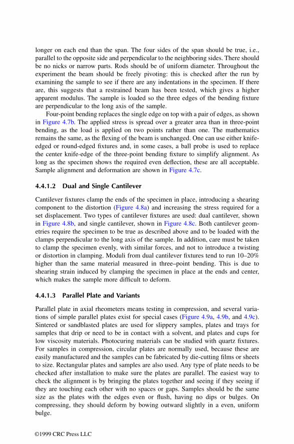
74 DN7036138Issue 3-2
BSS09006: GPRS System Feature Description
Id:0900d80580590b54
Requirements for GPRS
Figure 16 Protocol stack of the Gb interface
The BSSGP protocol functions are BSSGP protocol encoding and decoding, BSSGP virtual connection (BVC) management, BSSGP data transfer, paging support, and flow control support.
The Network Service Control is responsible for the following tasks:
• NS protocol encoding and decoding • NS data transfer • NS Service Data Unit (NS SDU) transmission • uplink congestion control on Network Service Virtual Connection (NS-VC) • load sharing between NS-VCs • NS-VC state management • GPRS-specific addressing, which maps cells to virtual connections • Network Service Virtual Link (NS-VL) management
The Frame Relay protocols provide a link layer access between the peer entities. Frame Relay offers permanent virtual circuits (PVC) to transfer GPRS signalling and data between the BSC and SGSN.
The Gb interface may consist of direct point-to-point connections between the BSS and the SGSN, or an intermediate Frame Relay network may be placed between both ends of the Gb interface. In the case of an intermediate Frame Relay network, both BSS and SGSN are treated as the user side of the user-to-network interface.
In Frame Relay, the physical link is provided by the Frame Relay Bearer channels. In the BSC this physical connection is a maximum of one 2 Mbit/s PCM for each active PCU. For load sharing and transmission security reasons, one PCU can have up to four Frame Relay Bearer channels that are routed to the SGSN through different transmis-sion paths. This means that the GPRS traffic from one PCU can be shared with a maximum of four physical PCM connections. The PCUs cannot be multiplexed to use a common bearer.
Network Service Control /Network Service Control protocol
Sub-Network Service Control /Sub-Network Service Control protocol
NS
BSS SGSNGb
LLC
BSSGP
NS
L1
RLC
MAC
RELAY
BSSGP
L1
NS
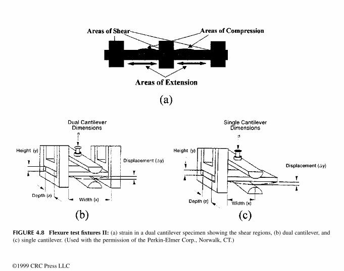
DN7036138Issue 3-2
75
BSS09006: GPRS System Feature Description Requirements for GPRS
Id:0900d80580590b54
The maximum combined Bearer Channel Access Rate is 2048 kbit/s within a PCU. This can be achieved by combining the different PCMs so that 32 subtimeslots are available for traffic. The step size is 64 kbit/s. The Committed Information Rate of Network Service Virtual Connections can be configured from 16 kbit/s up to the Access Rate of the Bearer channel in 16 kbit/s steps. On PCU2-E, the maximum combined Bearer Channel Access Rate is 4 x 2048 kbit/s. This can be achieved by combining the different PCMs so that 4 groups of 32 subtimeslots are available for traffic.
In the Nokia Siemens Networks implementation each PCU represents only one Network Service Entity (NSE), unless Multipoint Gb and Packet Control Unit (PCU2) Pooling are used.
Figure 17 Gb interface between the BSC and SGSN when Frame Relay (FR) is used
For more information on the NS and BSSGP protocols, refer to BSC-SGSN Interface Specification, Network Service Protocol (NS) and BSC-SGSN Interface Specification, BSS GPRS Protocol (BSSGP).
For more information on configuring and handling the Gb interface, see Enabling GPRS in BSC, Frame Relay Bearer Channel Handling, (FU) and Frame Relay Parameter Handling (FN).
5.3 Additional GPRS hardware needed in BSCi and BSC2iGSWB extension (optional)The PCU requires a GSWB extension (2 per BSC) for multiplexing the 256 Abis sub-timeslots. The second PCU plug-in unit for the BSC requires an extension of the GSWB with a third SW64B plug-in unit.
ET5C cartridge (optional)Additional ET5C cartridges are optional. They are needed to increase the amount of external PCMs, in BSCi from 56 to 88 and in BSC2i from 80 to 144. The additional PCMs may be used for Gb over Frame Relay.
BCSU 0
GSWB
FR
PCU
ET
PCM-TSL
bearer channelID=1name=BSC1time slots:1-31access rate:1984 kbit/s
SGSN
BSC

76 DN7036138Issue 3-2
BSS09006: GPRS System Feature Description
Id:0900d80580590b57
Radio network management for GPRS
6 Radio network management for GPRSFor Radio Network Configuration Management the preconditions are that the PCU and Gb interface have been created and configured. In the case of Frame Relay, the user builds the Gb interface in two phases: first the Frame Relay bearer channels are created, then the NS layer. Before enabling GPRS on a cell level, the user needs to create the Routing Area. See Activating and testing BSS9006: GPRS for detailed instructions.
6.1 Routing AreaMobility management in the GPRS network is handled in a similar way to the existing GSM system. One or more cells form a Routing Area (RA), which is a subset of one Location Area (LA). The Routing Area is unique within a Location Area. As Routing Areas are served by SGSNs, it is important to keep in mind the network configuration plan and what has been defined in the SGSN, before configuring the BSC side. One Routing Area is served by one SGSN.
When creating a Routing Area the user identifies the obligatory parameters mobile country code (MCC), mobile network code (MNC), location area code (LAC), and routing area code (RAC). Routing Areas are created in the BSS Radio Network Configuration Database (BSDATA).
The MCC, MNC, LAC and RAC parameters constitute the routing area identification (RAI):
RAI = MCC+MNC+LAC+RAC
The Routing Area and the BTS are linked logically together by the RAI. Routing Areas are used in the PCU selection algorithm which selects a serving PCU for the cell when the operator enables the GPRS traffic in the cell.
Figure 18 Relationship of Routing Areas and PCUs
Optimal Routing Area sizePaging signalling to mobiles is sent, for example, over the whole Location Area/Routing Area. An optimal Routing Area (RA) is balanced between paging channel load and
BTS
RA 2
RA n
BTS
BTS
BTS
BTS
BTS
BTS
RA 1
SGSN
BSCLA
PCU 1
PCU 0
PCU 2
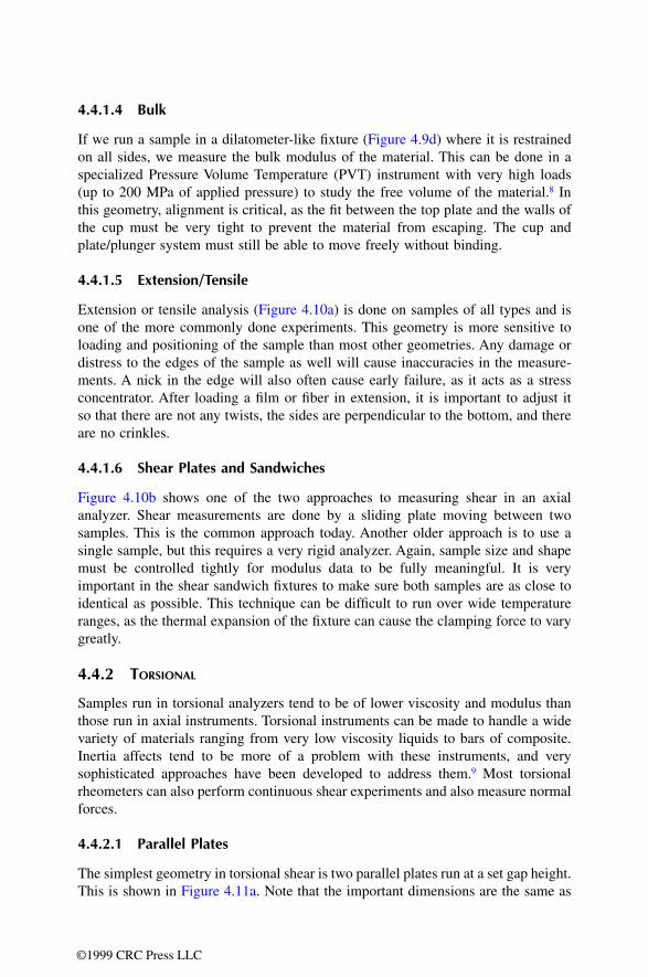
DN7036138Issue 3-2
77
BSS09006: GPRS System Feature Description Radio network management for GPRS
Id:0900d80580590b57
Routing Area updates. Refer to GPRS radio connection control for more information on paging.
If the Routing Area size is too large, paging channels and capacity will be saturated due to limited LAPD, Abis or radio interface CCCH paging capacity. On the other hand, with a small Routing Area there will be a larger number of Routing Area updates. Paging channel capacity is shared between the paging of the existing GSM users to the Location Areas (LA) and the GPRS users to the Routing Area. Based on the traffic behaviour of subscribers and the performance of the network (in terms of paging suc-cess), it is possible to derive guidelines regarding the maximum number of subscribers per LA/RA.
The Routing Area dimensioning is similar to the dimensioning of the Location Area of the existing GSM service. Routing Area dimensioning balances paging traffic from sub-scribers and the paging capacity offered by a given paging channel configuration. The number of pages that are sent by the BTS within an LA/RA indicates the number of mobile terminating calls that are being sent to subscribers in the LA/RA. The paging demand thus depends on three factors:
• the number of mobile terminating calls • the number of subscribers in the LA/RA • paging parameters defined by the operator in the SGSN.
The higher the number of mobile terminating sessions for subscribers in the Routing Area, the higher the number of pages that have to be sent by the BTS in the Routing Area. The success of paging, that is the number of times that a paging message has to be resent before it is answered, also has a profound effect on paging traffic. Paging traffic can thus be observed by means of:
• the number of pages per second per user • the number of subscribers • the paging success ratio.
The Nokia Siemens Networks infrastructure allows a combined Routing Area and Location Area paging by implementing the Gs interface between the SGSN and MSC/HLR. An attached GPRS mobile must send a Routing Area Update to the SGSN each time it changes Routing Area. The SGSN then forwards the relevant location area update information to the MSC reducing the RACH and AGCH load. The conclusion is that the signalling load is highly dependent on the parameters. In the same LA/RA, the paging load should be monitored.
☞ The smallest cell in the LA/RA will set the paging channel limit where combined channel structure is in use. Combined channel structure is possible if the cell is GPRS enabled (Routing Area exists).
6.2 PCU selection algorithmThe PCU selection algorithm in the BSC distributes GPRS traffic capacity between PCUs. Traffic is distributed on a cell level when the user enables GPRS in the cell. The algorithm then selects which PCU takes care of the traffic of a certain cell.
When GPRS is enabled, each cell is situated in a Routing Area. In the Radio Network, each Routing Area has its own object, to which the user defines the Network Service Entity Identifiers (NSEI) serving the Routing Area. The NSEIs are further discussed in
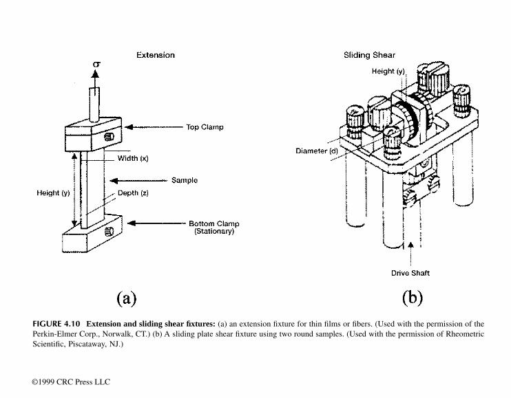
78 DN7036138Issue 3-2
BSS09006: GPRS System Feature Description
Id:0900d80580590b57
Radio network management for GPRS
Gb interface configuration and state management. The Nokia Siemens Networks imple-mentation is such that one PCU corresponds to one NSEI (unless Multipoint Gb and Packet Control Unit (PCU2) Pooling are used), and thus it can be said that the function of the PCU selection algorithm is to distribute GPRS traffic capacity between these NSEIs.
The algorithm locates the cells (BVCIs) in the same BCF to the same NSEI. The algo-rithm also tries to locate the cells which have adjacencies between each other to the same NSEI. If there are no NSEIs with the same BCF or with adjacencies then the algo-rithm selects the NSEI to which the smallest number of GPRS capable traffic channels, defined with the parameter max GPRS capacity (CMAX), is attached. Traffic channels are counted on TRXs which are GPRS enabled but not extended or super-reuse TRXs. Only unlocked NSEIs are selected. The NSEI is unlocked when it has at least one of its NS-VCs unlocked.
If a Dynamic Abis Pool is defined for a TRX in a cell and when GPRS is enabled for the cell, the same NSEI (PCU) is selected for the cell as for the Dynamic Abis Pool. In this case the PCU selection algorithm is not used.
The operator can choose whether the selected NSEI uses IP or FR transport with the parameter transport type (TRAT). The parameter cannot be used with manual NSEI selection. If no transport type is specified the default is that neither IP nor FR is preferred in the PCU selection algorithm.
The NSEIs can also be selected manually. If manual selection is used the PCU selection algorithm is not used. For more information on manual selection refer to Activating and Testing BSS9006: GPRS and Base Transceiver Station Handling in BSC (EQ).
For information on the PCU selection algorithm when Packet Control Unit (PCU2) Pooling is used, see chapter Functionality of Packet Control Unit (PCU2) Pooling in Packet Control Unit (PCU2) Pooling under Feature descriptions/Data in the PDF view.
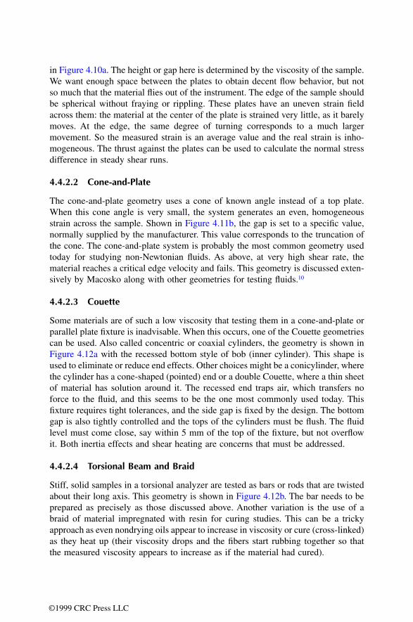
DN7036138Issue 3-2
79
BSS09006: GPRS System Feature Description Gb interface configuration and state management
Id:0900d80580590b5a
7 Gb interface configuration and state manage-mentThe BSC has the following functions in connection with the Gb interface:
• load sharing • NS-VC management • NS-VL management (IP) • BVC management • recovery.
Only Gb over Frame Relay is covered in these guidelines. For information on Gb over IP, see Gb over IP in BSC.
For information on Multipoint Gb Interface, see Multipoint Gb Interface under Feature descriptions/Data in the PDF view.
7.1 Protocol stack of the Gb interfaceThe Gb interface has a protocol stack consisting of three layers: Physical Layer, Network Service Layer (NS) and the Base Station System GPRS Protocol (BSSGP). The Network Service Layer further divides into Sub-network Service and Network Service Control. The Sub-network Service uses either Frame Relay or UDP/IP protocol.
Figure 19 The protocol stack on the Gb interface
Network Service Virtual Connection (NS-VC) NS-VCs are end-to-end virtual connections between the BSS and SGSN. The physical link in the Gb interface is the Frame Relay Bearer channel or UDP/IP connection.
In the case of Frame Relay, an NS-VC is the permanent virtual connection (PVC) and corresponds to the Frame Relay DLCI (Data Link Connection Identifier) together with
Network Service Control /Network Service Control protocol
Sub-Network Service Control /Sub-Network Service Control protocol
NS
BSS SGSNGb
LLC
BSSGP
NS
L1
RLC
MAC
RELAY
BSSGP
L1
NS
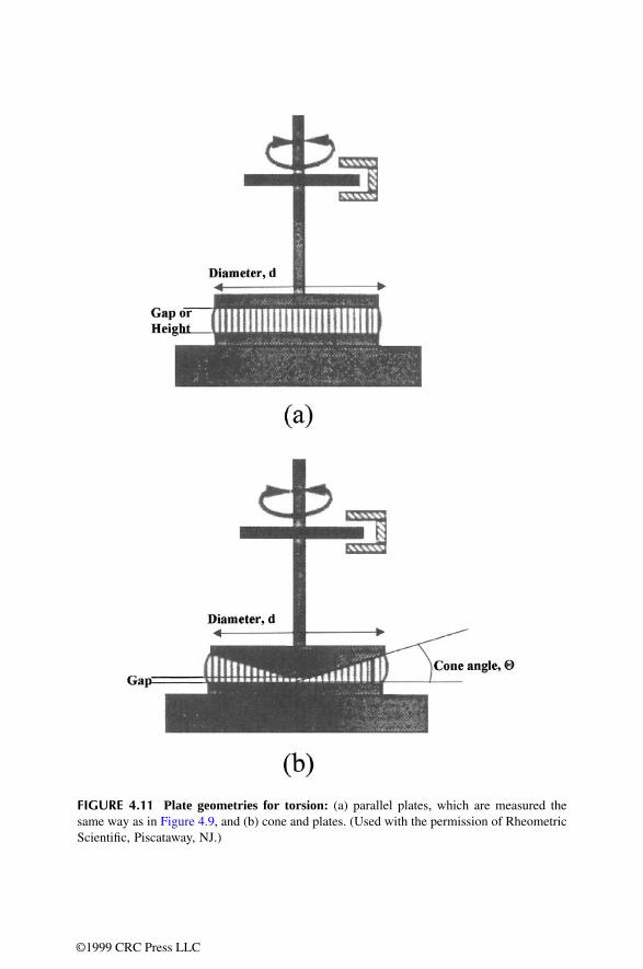
80 DN7036138Issue 3-2
BSS09006: GPRS System Feature Description
Id:0900d80580590b5a
Gb interface configuration and state management
the Bearer channel identifier. Each NS-VC is identified by means of a Network Service Virtual Connection Identifier (NS-VCI).
Network Service Entity (NSE)NSE identifies a group of NS-VCs in the BSC. The NSEI is used to identify the Network Service Entity that provides service to a BSSGP Virtual connection (BVC). One NSE is configured between two peer NSs. At each side of the Gb interface, there is a one-to-one correspondence between a group of NS-VCs and an NSEI. The NSEI has an end-to-end significance across the Gb interface at NS level, but only local significance at the BSSGP level. One NSE per PCU is supported and within one NSE a maximum of four NS-VCs are supported.
Network Service Virtual Connection GroupAccording to the 3GPP standard (TS48.016), the Network Service Virtual Connection Group groups together all NS-VCs providing communication between the same peer NS entities. One NS-VC group is configured between two peer NS entities. This grouping is performed by administrative means. At each side of the Gb interface, there is a one-to-one correspondence between a group of NS-VCs and an NSEI. The NSEI has an end-to-end significance across the Gb interface.
BSSGP Virtual Connection (BVC)BVCs are communication paths between peer NS user entities on the BSSGP level. Each BVC is supported by one NSE and it is used to transport Network Service Service Data Units (NS SDUs) between peer NS users.
Each BVC is identified by means of a BVCI which has end-to-end significance across the Gb interface. Each BVC is unique between two peer NSs.
Within BSS the user identifies a cell uniquely by a BVCI. The BVCI value 0000H is used for signalling and the value 0001H is reserved for point-to-multipoint (PTM). PTM is not supported. All other values can be used for cell identifiers.
Link Selector Parameter (LSP)All BSSGP UNITDATA PDUs related to an MS are passed to NS with the same LSP. This preserves the order of BSSGP UNITDATA PDUs, since the LSP is always mapped to a certain NS-VC. LSP has only local significance at each end of the Gb interface.
Frame Relay Permanent Virtual Connection (PVC)See Network Service Virtual Connection (NS-VC).
7.2 Load sharing functionThe BSC's load sharing function distributes all uplink Network Service Service Data Units (NS SDUs) among the unblocked NS-VCs within the NSE on the Gb interface. The use of load sharing also provides the upper layer with seamless service upon failure or user intervention by reorganising the SDU traffic between the unblocked NS-VCs. When creating the NS-VC the operator gives a CIR value (bit/s).
The reorganisation may disturb the order of transmitted SDUs. All NS SDUs to be trans-mitted over the Gb interface towards the SGSN are passed from BSSGP to NS along with the Link Selector Parameter (LSP). All the NS SDUs of an MS have the same LSP.
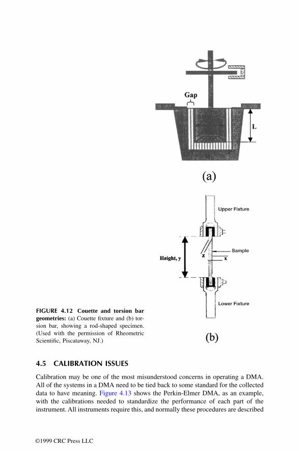
DN7036138Issue 3-2
81
BSS09006: GPRS System Feature Description Gb interface configuration and state management
Id:0900d80580590b5a
However, several MSS may use the same LSP. NS SDUs with the same LSP are sent on the same NS-VC.
The load sharing functions of the BSC and SGSN are independent. Therefore, uplink and downlink NS SDUs may be transferred over different NS-VCs. SGSN distributes downlink NS SDUs.
7.3 NS-VC management functionThe Network Service Virtual Connection (NS-VC) management function is responsible for the blocking, unblocking, resetting, and testing of NS-VCs. NS-VC management pro-cedures can be triggered by both the BSC and the SGSN.
Only one substate (BL-US, BL-SY or BL-RC) is valid at a time when an NS-VC is blocked. The BL-US state overrides both the BL-SY and BL-RC states. The BL-SY state overrides the BL-RC state. The BL-RC state does not override any other blocking state, so it is only possible when the NS-VC is unblocked. An exception is when the NS-VC is in the BL-SY state and SGSN initiates an NS-RESET. The NS may be reset only when using Frame Relay. Refer to NS-VC reset for more information.
NS-VC blockingWhen an NS-VC is unavailable for BSSGP traffic, the NS-VC is marked as blocked by the BSC and the peer NS is informed by means of the blocking procedure.
The BSC blocks an NS-VC when:
• the user locks the NS-VC, thus making it unavailable for BSSGP traffic; the cause sent to SGSN is 'O & M intervention'; operational state is BL-US.
• an NS-VC test fails; the cause sent to SGSN is 'Transit network failure'; operational state is BL-SY
• Frame Relay detects unavailability of a bearer or PVC; the cause sent to SGSN is 'Transit network failure'; operational state is BL-SY
During user block the BSC marks the NS-VC as user blocked, informs peer NSs, and reorganises BSSGP traffic to use other unblocked NS-VCs of the NSE. User-triggered blocking is started only when the PVC or the bearer is available, otherwise the NS-VC is marked as user blocked and the block procedure is skipped. The BSC cancels any pending NS-VC management procedure and related alarm.
After NS-VC test failure the NS-VC is marked as system blocked, the BSC raises the alarm NETWORK SERVICE VIRTUAL CONNECTION TEST PROCEDURE FAILED (3025) and blocks the NS-VC towards the SGSN through any 'live' NS-VC within the NSE, blocked or unblocked. The BSC also initiates the NS-VC reset procedure. BSSGP traffic is reorganised to use other unblocked NS-VCs of the NSE. If the NS-VC is user
State Possible substates
Unblocked (WO-EX Available) –
Blocked BL-US (unavailable by user)
BL-SY (unavailable by system)
BL-RC (unavailable by remote user)
Table 31 NS-VC operational states

82 DN7036138Issue 3-2
BSS09006: GPRS System Feature Description
Id:0900d80580590b5a
Gb interface configuration and state management
blocked while reset is attempted, the reset is stopped, the user block is accepted and the state of the NS-VC is user blocked. The BSC cancels the NETWORK SERVICE VIRTUAL CONNECTION TEST PROCEDURE FAILED (3025) alarm after the next suc-cessful test procedure on the NS-VC. If the NS-VC is already user blocked, the BSC does not change the NS-VC state, it sets no alarms, and sends no block to the SGSN, but instead initiates the NS-VC reset procedure. After a successful reset, the test proce-dure is continued. If the NS-VC reset procedure fails after all the retries, no alarm is set.
After the BSC detects the unavailability of a PVC or a bearer, the related NS-VC(s) is marked as system blocked and the BSC blocks it towards the SGSN through any 'live' NS-VC within the NSE, blocked or unblocked. The BSC sets the NETWORK SERVICE VIRTUAL CONNECTION UNAVAILABLE (3020) alarm for the blocked NS-VC(s) and reorganises BSSGP traffic to use other unblocked NS-VCs of the NSE. If the NS-VC(s) is already user blocked, when the unavailability of a PVC or bearer is detected, the BSC does not change the state of the NS-VC(s), does not set an alarm, and does not send a block to the SGSN, but instead stops the NS-VC(s) test. If the NS-VC(s) is already system blocked, the BSC actions are the same but it also stops a possible ongoing reset procedure.
During an SGSN-initiated block, if the NS-VC is not user, system or remote blocked, the BSC marks the NS-VC as remote blocked, reorganises BSSGP traffic to use other unblocked NS-VCs of the NSE and sets the alarm NETWORK SERVICE VIRTUAL CONNECTION UNAVAILABLE (3020). If the NS-VC is user, system or remote blocked, then the BSC does not change the NS-VC state and acknowledges the received block back to the SGSN.
In all the above cases, if the blocked NS-VC is the last one in the NSE, it means that all BSSGP traffic to/from PCU-managed cells stops on the Gb interface, and the BSC sends System Information messages to relevant cells indicating that GPRS is disabled. The BSC sets the NETWORK SERVICE ENTITY UNAVAILABLE (3019) alarm when PVC/bearers are unavailable, the SGSN initiates the block, or related BVCs are implic-itly blocked.
NS-VC unblockingWhen the NS-VC becomes available again for BSSGP traffic, the peer NS is informed by means of the unblocking procedure, after which the NS-VC is marked as unblocked by the BSC.
The BSC unblocks an NS-VC after:
• user unlocks the NS-VC thus making it available for BSSGP traffic. • the system initiates a NS-VC reset, for example after a test failed NS-VC is reset or
after a reset of a NS-VC whose bearer is resumed as available for NS level.
During user unblock the BSC informs the peer NS and marks the NS-VC as unblocked after receiving an acknowledgement from the peer NS. New BSSGP traffic now uses this new NS link (refer to Load sharing function). User triggered unblocking starts only when the PVC or the bearer is available, otherwise the BSC marks the NS-VC as system blocked and skips the unblock procedure. The BSC sets the NETWORK SERVICE VIRTUAL CONNECTION UNBLOCK PROCEDURE FAILED (3021) alarm and marks the NS-VC unblock as pending until NS-VC unblock can be performed and the alarm is cancelled by the BSC.
DN7036138Issue 3-2
83
BSS09006: GPRS System Feature Description Gb interface configuration and state management
Id:0900d80580590b5a
During system unblock the BSC cancels the NETWORK SERVICE VIRTUAL CONNEC-TION UNAVAILABLE (3020) alarm. The BSC does not start system initiated unblock if the NS-VC is user blocked.
During SGSN initiated unblock, the BSC marks the NS-VC as unblocked and cancels the NETWORK SERVICE VIRTUAL CONNECTION UNAVAILABLE (3020) alarm if the NS-VC is not user or system blocked. If the NS-VC is user blocked, then the BSC is not able to unblock the NS-VC. The NS-VC remains user blocked and the BSC initiates the NS-VC blocking procedure by returning an NS-BLOCK PDU to the SGSN with the cause "O & M intervention". This NS-BLOCK PDU is sent on the NS-VC where the NS-UNBLOCK PDU was received. If the NS-VC is system blocked with no BSC initiated unblock procedure on, then the BSC is not able to unblock the NS-VC. The NS-VC remains system blocked and the BSC initiates the NS-VC reset procedure by returning an NS-RESET PDU to the SGSN with the cause "PDU not compatible with the protocol state". If the NS-VC is system blocked with a BSC initiated unblock procedure on, then the BSC acknowledges the received PDU back to the SGSN and it is interpreted as an acknowledgement for the sent NS-UNBLOCK PDU.
In all of the above cases, if the unblocked NS-VC is the first one in the NSE, it means that BSSGP traffic to/from PCU-managed cells can start again on the Gb interface, and the BSC sends System Information messages to relevant cells indicating that GPRS is enabled. The BSC triggers the BVC reset procedure for signalling BVC and cell-specific BVCs, and cancels the NETWORK SERVICE ENTITY UNAVAILABLE (3019) alarm in cases of system unblock and SGSN initiated unblock.
For more information, see BSC-SGSN Interface Specification, Network Service Protocol (NS).
NS-VC resetThe NS-VC reset procedure is used to reset an NS-VC to a determined state between peer NSs.
During a reset triggered by user unblock, the BSC marks the NS-VC as system blocked, informs the peer NS, and reorganises BSSGP traffic to use other unblocked NS-VCs of the NSE. After a completed reset procedure, the BSC starts a test procedure (periodic testing) and after successful testing unblocks the NS-VC. The BSC starts a reset trig-gered by user unblock only when the PVC or the bearer is available, otherwise it marks the NS-VC as system blocked, skips the reset procedure, and sets the NETWORK SERVICE VIRTUAL CONNECTION RESET PROCEDURE FAILED (3023) alarm. The BSC sets the NS-VC reset as pending until the NS-VC reset can be performed and then cancels the alarm.
During an SGSN-initiated reset, the BSC marks the NS-VC as remote blocked and sets the NETWORK SERVICE VIRTUAL CONNECTION UNAVAILABLE (3020) alarm if the NS-VC is not user or remote blocked. If the NS-VC is user or remote blocked, then the
Case where the BSC resets an NS-VC Cause sent to the SGSN
The user sets up, modifies or unlocks an NS-VC O & M intervention
System or BCSU restarts Equipment failure (see BCSU restart)
Periodic NS-VC test fails Transit network failure
Frame Relay detects an unavailability of a bearer Transit network failure
Table 32 NS-VC reset cases

84 DN7036138Issue 3-2
BSS09006: GPRS System Feature Description
Id:0900d80580590b5a
Gb interface configuration and state management
BSC does not change the state, but acknowledges the received reset back to SGSN and initiates the test procedure. If the NS-VC is system blocked, then the action depends on whether the NS-VC reset is ongoing or not. If the NS-VC reset is ongoing, then the received NS-RESET is interpreted as an acknowledgement and the BSC acknowledges it back to the SGSN and initiates the test procedure. If the NS-VC reset is stopped, then the BSC changes the NS-VC state to remote blocked (to get the NS-VC up during SGSN initiated NS-VC unblock), acknowledges the received reset back to the SGSN, and ini-tiates the test procedure.
In all the above cases, if the blocked NS-VC is the last one in the NSE, it means that all BSSGP traffic to/from PCU-managed cells stops on the Gb interface, and the BSC sends System Information messages to relevant cells indicating that GPRS is disabled. The BSC sets the NETWORK SERVICE ENTITY UNAVAILABLE (3019) alarm in a SGSN initiated reset and blocks the related BVCs implicitly.
For more information, see BSC-SGSN Interface Specification, Network Service Protocol (NS).
NS-VC testThe NS-VC test procedure is used when the BSC checks that end-to-end communica-tion exists between peer NSs on a given NS-VC. The user can define the test procedure with the PRFILE parameter TNS_TEST. When end-to-end communication exists, the NS-VC is said to be 'live', otherwise it is 'dead'. A 'dead' NS-VC cannot be in the unblocked state, instead it is always marked as blocked and a reset procedure is initi-ated.
Both sides of the Gb interface may initiate the NS-VC test independently from each other. This procedure is initiated after successful completion of the reset procedure, and is then periodically repeated. The test procedure runs on unblocked NS-VCs and also on user blocked and remote blocked NS-VCs, but not on system blocked NS-VCs, except after NS-VC reset. The test procedure is stopped when the underlying bearer or PVC is unavailable.
For more information, see BSC-SGSN Interface Specification, Network Service Protocol (NS).
7.4 BVC management functionThe BVC management function is responsible for the blocking, unblocking and reset of BVCs. The BVC reset procedure can be triggered by both the BSC and the SGSN, but BVC blocking and unblocking procedures can only be triggered by the BSC.
The user can output the BVC operational state with the command EQO. The possible states are shown in the table below.
Operational state Explanation
WO-EX The BVC is operational.
Table 33 BVC operational states

DN7036138Issue 3-2
85
BSS09006: GPRS System Feature Description Gb interface configuration and state management
Id:0900d80580590b5a
BVC blocking and unblockingBVC blocking is initiated by the BSC to remove a BVC from GPRS data use.
The BSC blocks a BVC after:
BVC unblocking is used only in an exceptional condition when the BSC receives an unexpected BVC-BLOCK-ACK PDU relating to a BVC that is locally unblocked. The BSC then unblocks the BVC with the BVC-UNBLOCK PDU.
For more information, see BSC-SGSN Interface Specification, BSS GPRS Protocol (BSSGP).
BVC resetA BVC reset is initiated by the BSC to bring GPRS data into use in a BVC. BVC reset is used instead of BVC unblock because of the dynamic configuration of BVCs in the SGSN.
BL-SY Unavailable by system.
The NSE is not functional, or a radio network object (a TRX, BTS or BCF) is blocked so that the cell does not have GPRS capability.
unblocked Either GPRS has been enabled in the cell and the BVC has been created in the SGSN, but the BVC's flow control is not yet operational, or the cell has no GPRS TSLs.
BVC conf lost The BVC has not been configured for the PCU, or the configuration has been lost from the PCU.
This situation can be resolved by disabling, and the re-enabling GPRS in the cell, or by executing BCSU swi-tchover.
unknown The enquired BVCI is outside the allowed value range, or the PCU does not report the state of the BVC within the time limit because of some fault situation. In the latter case the user should check the status of the PCU.
Operational state Explanation
Table 33 BVC operational states (Cont.)
Case where the BSC blocks a BVC Cause sent to the SGSN
A user disables GPRS in a cell, disables the last GPRS-supporting TRX in a cell, blocks the BCCH TRX in a cell or deletes a BVC by disabling GPRS in a cell.
O & M intervention
A user or system block of the last NS-VC of the NSE serving the BVC; related BVCs are locally blocked by the BSC.
No indication is sent to the SGSN.
SGSN initiates a BVC-RESET procedure (if neces-sary).
BVCI-blocked
A cell level fault, for example at the beginning of site reset, BTS reset or TRX reset.
Equipment failure
Table 34 BVC blocking cases
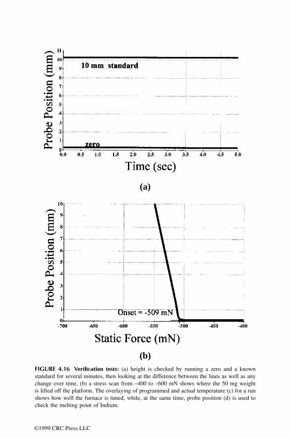
86 DN7036138Issue 3-2
BSS09006: GPRS System Feature Description
Id:0900d80580590b5a
Gb interface configuration and state management
With the BVC reset the underlying network service must be available for use, otherwise the BSC marks the BVC as unblocked in order to get the BVC up and running when the NS-level becomes available again, skips the BVC reset procedure, and sets the BSSGP VIRTUAL CONNECTION RESET PROCEDURE FAILED (3031) alarm. The BSC cancels the alarm after the next successful BVC block, unblock or reset.
For more information, see BSC-SGSN Interface Specification, BSS GPRS Protocol (BSSGP).
7.5 Recovery in restart and switchoverIn a recovery situation the BCSU and PCU are always handled together as a pair. The diagnostics of the PCU is included in the diagnostics of the BCSU. Diagnostics is run automatically, but the operator may also start the diagnostics routine if needed.
BCSU restartIf the Gb interface uses Frame Relay, after user or system initiated BCSU restart, the BSC recreates the Gb interface on the restarted PCU right after Frame Relay level set-up. The PCU starts Frame Relay level periodic polling towards the SGSN. Spontaneous indications come from the SGSN to the BSC's PCU on Frame Relay level about bearer channel availability for NS-VCs.
First all NS-VCs are created, then all BVCs are created after cell-specific block indica-tions. The PCU maintains only user blocked information of NS-VCs. The NS-VCs which have received DLCIs from the network are reset when the bearer channel is available. The PCU sets others as pending and raises the NETWORK SERVICE VIRTUAL CON-NECTION RESET PROCEDURE FAILED (3023) alarm for each NS-VC.
The reset procedure is completed when the PCU receives a suitable DLCI from the network, and cancels the alarm. The PCU then initiates the test procedure on the suc-cessfully reset NS-VCs, and after successful tests unblocks all tested NS-VCs, and resets the signalling BVC. After successful BVC reset the uplink BSSGP data delivery is possible on that BVC. After an initial flow control procedure for the BVCs, also downlink BSSGP data delivery is possible on that BVC. Flow control is discussed in more detail in GPRS radio connection control.
BCSU switchoverIf the Gb interface uses Frame Relay, after BCSU switchover (either user or system ini-tiated), the BSC recreates the Gb interface on the target PCU right after Frame Relay
Case where BSC resets a BVC Cause sent to the SGSN
A user enables GPRS in a cell, enables the first GPRS-supporting TRX in a cell, deblocks the BCCH TRX in a cell, or creates a BVC by enabling GPRS in a cell.
O & M intervention
A user or system unblock of the first NS-VC of the NSE serving the BVC (signalling BVC is reset first, then the rest).
Network service transmission capacity modified from zero kbit/s to greater than zero kbit/s
A cell restart, for example after site, BTS or TRX reset, when the restarted object is working
Equipment failure
Table 35 BVC reset cases
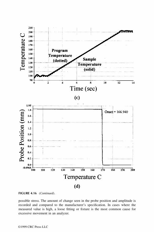
DN7036138Issue 3-2
87
BSS09006: GPRS System Feature Description Gb interface configuration and state management
Id:0900d80580590b5a
level set-up. The Gb interface configuration is from the source PCU and the setting up of the Gb interface is similar to what was described in section BCSU restart.
The BSC does not send NS level blocks from the source PCU in order not to interrupt the BVC configurations of the SGSN.
Forced BCSU switchover The operation in a forced BCSU switchover is very similar to the operation in a BCSU restart. The PCU releases all PCU PCM connections related to the restarted PCU. All GPRS data connections will drop after the PCU PCM connections are released.
After the switchover — whether user or system initiated — the BSC unblocks TRXs and delivers new territory to the PCU.
Controlled BCSU switchoverA controlled BCSU switchover is either a user or a system initiated action. The user defines between which BCSUs the switchover is made. The system cancels the swi-tchover command if the execution would lead to a situation where some of the circuit switched calls would drop. If the switchover is cancelled, the original working BCSU is restored back to the working state. If a PCU gets faulty the system may initiate the BCSU switchover.
☞ Only GPRS data connections that are connected to the PCU are released.
In a successful switchover, the BSC moves the control of the working BCSU/PCU pair to the spare BCSU/PCU pair as in the forced switchover, but data is copied only from the working BCSU to the spare BCSU. Because GPRS data is not copied to the PCU, the PCU sees the data as lost and thus releases all its PCU PCM connections and unblocks its BTSs. The BSC resets the new spare PCU to the working state, and defines its new GPRS territory.
If the switchover is cancelled for some reason, the original working PCU is restored back to the working state, and the BSC resumes GPRS territory updatings. The BSC allows new GPRS connection setups in the old working PCU again. After an unsuccessful swi-tchover the PCU uses the same GPRS territory as it had before the switchover. At the end of the switchover the spare PCU is restarted regardless of the switchover being suc-cessful or not.

88 DN7036138Issue 3-2
BSS09006: GPRS System Feature Description
Id:0900d80580590b5d
Radio resource management
8 Radio resource managementGPRS radio resource management in BSC involves two processes: division of radio timeslots between circuit switched and packet switched timeslot territories on the one hand, and channel allocation for individual MSS within the PS territory on the other hand.
Division of radio timeslots into territories means that BSC selects the radio timeslots that shall be used primarily for packet data traffic and which shall therefore be avoided in traffic channel allocation for circuit switched services. During channel allocation for indi-vidual MSS PCU assigns PS territory timeslots for GPRS TBFs.
The radio resource management function which is responsible for the CS/PS territory management also takes care of traffic channel allocation for circuit switched calls. PCU has its own radio channel allocation that takes care of allocating channels for GPRS TBFs.
Up to seven uplink GPRS TBFs can share the resources of a single radio timeslot. Uplink and downlink scheduling processes are independent of each other, and for downlink up to nine GPRS TBFs can share the resources of a single radio timeslot.
To enable GPRS traffic in a cell, and to initiate the creation of the necessary PS territory, the operator has to first activate GPRS in the BSC with the cell-specific parameter GPRS enabled (GENA) and define which TRXs are capable of GPRS with the parameter GPRS enabled TRX (GTRX).
Only after the BSC has an update on the BTS parameters and other parameters indicat-ing GPRS usage, does it count the number of default and dedicated GPRS timeslots in the BTS and select a TRX where it starts to establish the GPRS territory.
The BSC can upgrade or downgrade the number of radio resources allocated for GPRS use according to the varying needs of the circuit switched and GPRS traffic. These pro-cedures are explained in detail in the sections below.
8.1 Territory methodThe BSC divides radio resources semipermanently between circuit switched services and GPRS, thus forming two territories. The PCU uses the GPRS territory resources. The initial territories are formed on a BTS-to-BTS basis according to the operator-defined parameters. The BSC can later broaden the GPRS territory based on the actual need and according to the requests of the PCU.
The circuit switched services have priority over GPRS in channel allocation within common resources. In principle, GPRS releases its resources as soon as they are needed for circuit switched traffic.
Only Full Rate and Dual Rate traffic channels are GPRS compatible, and within a cell only such channels may be configured into the PS territory. GPRS capacity can be divided into three types:
• default GPRS capacity • dedicated GPRS capacity • additional GPRS capacity.
GPRS has a predefined set of resources which it can utilise when the circuit switched load allows. This is referred to as the default GPRS capacity. Part of these default traffic channels can be reserved solely for GPRS and this means they are blocked altogether

DN7036138Issue 3-2
89
BSS09006: GPRS System Feature Description Radio resource management
Id:0900d80580590b5d
from circuit switched use. This is referred to as dedicated GPRS capacity. The user can modify these two capacities by using the respective parameters default GPRS capacity (CDEF) and dedicated GPRS capacity (CDED).
Additional GPRS capacity is referred to with radio timeslots that are above and beyond the default GPRS capacity and that the BSC has allocated for GPRS use according to the requests of the PCU. GPRS territory size can be restricted by the user-modifiable parameter max GPRS capacity (CMAX). There is a GPRS territory update guard time defining how often the PCU can request new radio timeslots for GPRS use.
Figure 20 Territory method in BSC
The BSC calculates these defined resources from percentages to concrete numbers of radio timeslots based on the number of traffic channel radio timeslots (both blocked and working) capable of Full Rate traffic in the TRXs with GPRS enabled (set with the param-eter GPRS enabled TRX (GTRX)). The super reuse TRXs (Intelligent Underlay Overlay) and the extended area TRXs (Extended Cell Range) are never included as available resources in the GPRS territory calculation. The calculation is as follows:
• the product of default GPRS capacity (CDEF) parameter and the number of radio timeslots is rounded down to a whole number.
• if default GPRS capacity (CDEF) parameter value is > 0 but the rounded product equals 0, then the territory size 1 is used
• default GPRS capacity (CDEF) parameter minimum value is 1. • max GPRS capacity (CMAX) parameter minimum value is 1 (range 1–100%).
The BSC starts to create the GPRS territory by first selecting the most suitable TRXs in the BTS according to its GPRS capability, TRX type, TRX configuration, and the actual traffic situation in the TRX.
The prefer BCCH frequency GPRS (BFG) parameter indicates if the BCCH-TRX is the first or the last choice for the GPRS territory or if it is handled equally with non-BCCH-TRXs.
The best candidate for GPRS territory according to the traffic load is the TCH TRX that holds the most idle successive Full Rate-capable (TCH/F or TCH/D) timeslots counted from the end of the TRX (timeslot 7). The GPRS timeslots are always allocated from TSL7 towards TSL0 per TRX. If there are two or more TRXs that have the same number of idle successive Full Rate-capable timeslots, then the TRX containing permanent TCH/F timeslots is preferred to one with Dual Rate timeslots to avoid wasting Half Rate capability in the GPRS territory. TRXs with permanent TCH/H timeslots or multislot HSCSD calls are also avoided, if possible.
TRX 1
TRX 2
BCCH
DefaultGPRS Capacity
DedicatedGPRS
Capacity
AdditionalGPRS
Capacity
Territory border moves based onCircuit Switched and GPRS traffic load
GPRSTerritory
CircuitSwitchedTerritory
MaxGPRS
Capacity

90 DN7036138Issue 3-2
BSS09006: GPRS System Feature Description
Id:0900d80580590b5d
Radio resource management
Having defined the GPRS capacity share and having selected the best TRX for GPRS, the BSC next begins a GPRS territory upgrade procedure where it allocates the selected radio timeslots of the TRX for GPRS use and informs the PCU.
GPRS territory upgradeThe BSC uses a GPRS territory upgrade procedure to allocate part of the resources for GPRS use. The BSC starts the GPRS territory upgrade procedure when the user enables GPRS in a BTS.
The number of timeslots given for GPRS use is defined by the operator with the param-eters dedicated GPRS capacity (CDED), default GPRS capacity (CDEF) and max GPRS capacity. All the defined timeslots cannot necessarily be delivered immediately due to the circuit switched traffic load of the BTS. However, the BSC fulfils the defined GPRS capacity as soon as possible. After the default capacity (which includes also the dedicated part) has been delivered, the PCU can request more resources for a GPRS territory upgrade based on the actual need caused by GPRS use.
Each GPRS territory upgrade concerns timeslots of one TRX; thus an upgrade is a TRX-specific procedure. The BSC performs upgrades of continuous sets of successive timeslots. Starting from the end of the first TRX in the GPRS territory, the BSC includes in a GPRS territory upgrade the timeslots according to need and availability.
If the GPRS territory cannot be extended to its full size due to a timeslot being occupied by circuit switched traffic, an intra cell handover is started. The aim of the handover is to move the circuit switched call to another timeslot and clear the timeslot for GPRS use (refer to the figure below). The BSC then continues with the upgrading of the GPRS ter-ritory after the release of the source channel of the handover. If the GPRS territory of a BTS needs more timeslots than one TRX can offer, the BSC selects a new TRX and starts to define the territory.
When the user enables GPRS in a cell, the BSC starts a handover to be able to allocate dedicated GPRS channels, even if the defined margin of idle timeslots is not met but there is at least one timeslot available.
The BSC starts a handover to move a non-transparent multislot HSCSD call, but not for a transparent multislot HSCSD call. For a transparent HSCSD call, the HSCSD timeslots are left inside the GPRS territory, although not as actual GPRS channels. The BSC extends the GPRS territory on the other side of the timeslots reserved for the transpar-ent HSCSD call.
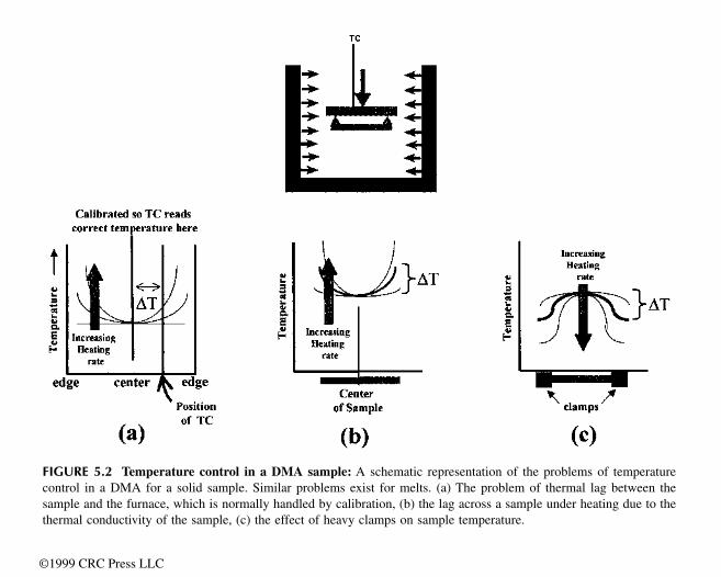
DN7036138Issue 3-2
91
BSS09006: GPRS System Feature Description Radio resource management
Id:0900d80580590b5d
Figure 21 GPRS territory upgrade when a timeslot is cleared for GPRS use with an intra cell handover
Situations leading to the starting of a GPRS territory upgrade are related to configuration and traffic channel resource changes. When the user adds GPRS capable TRXs in a BTS, it results in an increase in the timeslot share that should be provided for GPRS traffic. The BSC starts the GPRS territory upgrade procedure when:
• the user enables GPRS in a cell • the user or BSC unblocks a GPRS enabled TRX thus enabling a pending GPRS ter-
ritory upgrade • the user or BSC unblocks a radio timeslot inside the GPRS territory enabling it to be
included in the GPRS territory • the BSC releases a circuit switched TCH/F causing the number of idle resources in
the BTS to increase above a margin that is required before GPRS territory upgrade can be started
• the BSC releases a circuit switched TCH/F beside the GPRS territory border (as a consequence of handover) so that the pending GPRS territory upgrade can be per-formed
• the PCU requests a GPRS territory upgrade.
Other general conditions for a GPRS territory upgrade are:
• previous GPRS territory change in the BTS has been completed • sufficient margin of idle TCH/Fs in the BTS • idle GPRS capable resources available in the BTS • available capacity in the PCU controlling the BTS.
The margin of idle TCH/Fs that is required as a condition for starting a GPRS territory upgrade is defined by the BSC parameter free TSL for CS upgrade (CSU). In fact, the parameter defines how many traffic channel radio timeslots have to be left free after the GPRS territory upgrade. When defining the margin, a two-dimensional table is used. In the two-dimensional table the columns are for different amounts of available resources (TRXs) in the BTS. The rows indicate a selected time period (seconds) during which probability for an expected downgrade is no more than 5%. The operator can modify the period with the BSC parameter CSU. The default value for the period length is 4 seconds.
= Circuit Switched territory
= GPRS territory
B S C C C C C
C
C
C C
C
C d d D D D
C C C C
C C C
C
GPRS territory upgrade
B = BCCH TSLS = SDCCH TSLC = Circuit Switched call
Default GPRS capacity (d)= 20%Dedicated GPRS capacity (D) = 10%
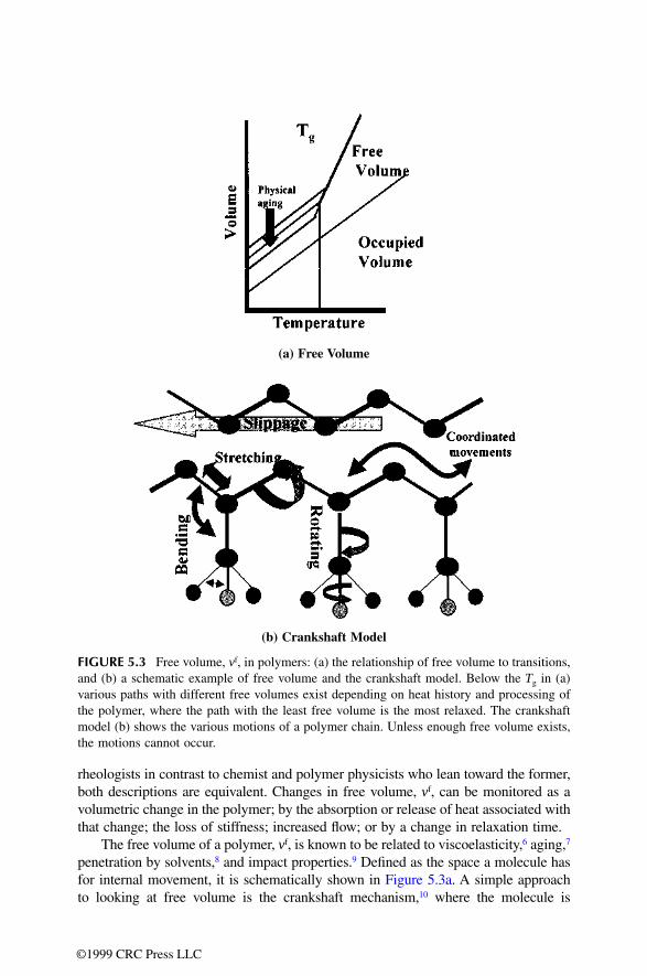
92 DN7036138Issue 3-2
BSS09006: GPRS System Feature Description
Id:0900d80580590b5d
Radio resource management
The user can define and modify with the parameter GPRS territory update guard time (GTUGT) the guard time, which the PCU has to wait between successive requests for GPRS territory configuration updates. The BSC obeys this guard time also when it performs GPRS territory upgrades to fulfil the operator-defined default GPRS territory.
If the conditions required for a GPRS territory upgrade are not met at the time the PCU requests a GPRS territory upgrade, the BSC simply does nothing but updates related statistics. There are three reasons for a GPRS territory upgrade request being rejected: lack of GPRS radio resources, circuit switched traffic load, and the capacity limit of the PCU unit. In case the PCU asks for several timeslots in one request and only a part of the requested resources are available, a statistics counter is updated.
In the GPRS territory upgrade, the PCU selects a free circuit from the PCUPCM and the BSC connects it to an Abis circuit. If an error occurs when connecting the PCUPCM circuit to the Abis circuit, the BSC cancels the upgrade and saves information on the detected fault. The BSC initiates a new GPRS territory upgrade after a guard period.
If two successive connection failures of a PCUDSP circuit with different Abis circuits occur, the BSC marks the PCUDSP channel as faulty and sets the alarm FAULTY PCUPCM TIMESLOTS IN PCU (3073).
Alarm GPRS/EDGE TERRITORY FAILURE (3273) is set if the GPRS territory size in the BTS is below the limit specified by the BTS specific radio network parameter default GPRS capacity (CDEF). The BSC has not been able to add more radio channels to the territory within the informing delay of the alarm.
Additional GPRS territory upgradeThe need for additional GPRS channels is checked when a new TBF is established or an existing TBF is terminated. The PCU will request additional channels, if a GPRS ter-ritory contains less channels than could be allocated to a mobile according to its multislot class, or if the average number of TBFs per TSL is more than 1.5 after the allocation of
TRXs 1 2 3 4 5 6 7 8 9 10 11 12 13 14 15 16
Time period: 0 s
0 0 0 0 0 0 0 0 0 0 0 0 0 0 0 0
1 s 0 1 1 1 2 2 2 2 2 2 3 3 3 3 3 3
2 s 1 1 2 2 2 3 3 3 3 4 4 4 4 5 5 5
3 s 1 1 2 3 3 3 4 4 4 5 5 6 6 6 6 6
4 s 1 2 2 3 4 4 4 5 5 6 6 6 7 7 7 7
5 s 1 2 3 3 4 5 5 5 6 6 7 7 7 8 8 8
6 s 1 2 3 4 4 5 5 6 6 7 7 8 8 8 9 9
7 s 1 2 3 4 5 5 6 7 7 7 8 8 9 9 9 9
8 s 1 3 4 4 5 6 6 7 7 7 8 9 9 9 9 9
9 s 1 3 4 5 5 6 7 7 8 8 9 9 9 9 9 9
10 s 2 3 4 5 6 7 7 8 8 8 9 9 9 9 9 9
Table 36 Defining the margin of idle TCH/Fs

DN7036138Issue 3-2
93
BSS09006: GPRS System Feature Description Radio resource management
Id:0900d80580590b5d
the new TBF (average TBF/TSL>1.5). These additional channels will be requested only if all GPRS default channels are already in the GPRS territory.
The number of additional channels the PCU will request is the greater of the following two numbers:
• the number of additional channels needed in the allocation according to the MS's multislot class (this criterion is used only when the GPRS territory contains fewer channels than the MS is capable of using), and
• the number of additional channels needed for the average number of allocated TBFs per TSL to be 1 (average TBF/TSL=1).
Example: The GPRS territory consists of one (default) channel and resources should be allocated for a downlink TBF of a multislot class 4 mobile. The PCU will first allocate one channel for the TBF and it will request for (at least) 2 more channels, as the mobile is capable of using 3 downlink channels. When the PCU receives this additional capacity, the TBF will be reallocated to utilise all channels.
Example: The GPRS territory consists of three channels (one default and two additional) and a mobile of multislot class 4 has a downlink TBF of three timeslots (performing ftp for example). One of the additional channels is taken into CS use, the territory is decreased to two channels, and the downlink TBF is reallocated to these channels. When the pre-viously reserved channel is freed from the CS side, a territory upgrade would be possi-ble, but nothing happens (no upgrade of the territory), because the system only checks for need for upgrade when a new TBF is established. However, if the existing TBF is ter-minated and a new one is established or if the concurrent uplink TBF is terminated the need and possibility of the territory upgrade is re-evaluated.
GPRS territory downgradeThe BSC uses a GPRS territory downgrade procedure when it needs to reduce the share of timeslots in the GPRS territory, for example when there is an increase in the circuit switched traffic load.
The BSC starts a GPRS territory downgrade procedure when
• the user disables GPRS in a cell • the user or BSC blocks the TRX that is carrying GPRS traffic • the user or BSC blocks the timeslot that is carrying GPRS traffic • the user or BSC blocks circuit switched resources causing the number of idle
resources in the BTS to decrease below the required margin • the BSC allocates a traffic channel for circuit switched use causing the number of
idle resources in the BTS to decrease below the required margin • the PCU requests for a GPRS territory downgrade
The PCU initiates a GPRS territory downgrade procedure for additional type GPRS radio timeslots. This means that the PCU has requested these timeslots for GPRS traffic in addition to the default capacity, but the need for additional timeslots has ceased. If the BSC cannot start a GPRS territory downgrade at the time the PCU requests it, the PCU will have to request a downgrade again after the territory update guard time has expired, if the need for the downgrade still exists.
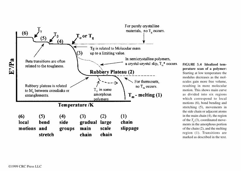
94 DN7036138Issue 3-2
BSS09006: GPRS System Feature Description
Id:0900d80580590b5d
Radio resource management
The operator defines the margin of idle TCHs that the BSC tries to maintain free in a BTS for the incoming circuit switched resource requests using the parameter free TSL for CS downgrade (CSD). If the number of idle TCH resources in the circuit switched territory of the BTS decreases below the defined margin, a GPRS territory downgrade is started if possible. The definition of the margin involves a two-dimensional table. One index of the table is the number of TRXs in the BTS. Another index of the table is the needed number of idle TCHs. Actual table items are percentage values indicating prob-ability for TCH availability during a one-second downgrade operation with the selected resource criterion. Default probability 95% can be changed through the free TSL for CS downgrade (CSD) parameter.
Additional GPRS territory downgradeAdditional channels are taken into CS use whenever more channels are needed on the CS side. The need for additional GPRS channels is always checked when an existing TBF is terminated. The PCU will request the removal of additional channels, if the average TBFs per TSL is less than 0.5 (average TBF/TSL<0.5).
8.2 Circuit switched traffic channel allocation in GPRS terri-toryThe BSC maintains a safety margin of idle traffic channels for circuit switched traffic by starting a GPRS territory downgrade when the number of free traffic channels in the circuit switched territory of a BTS decreases below the limit defined by the parameter free TSL for CS downgrade (CSD). Depending on the size of the margin and on the amount of traffic on the BTS, new circuit switched traffic channel requests may come before the GPRS territory downgrade procedure has been completed. During a sudden burst of traffic channel requests, the BSC may not be able to maintain the margin with the GPRS territory downgrade procedure and the circuit switched territory may run out of idle traffic channels.
TRXs 1 2 3 4 5 6 7 8 9 10 11 12 13 14 15 16
TCH0
94 84 76 69 63 58 54 50 48 45 43 41 40 38 37 35
1 99 98 96 93 91 87 85 82 79 77 74 72 70 68 66 64
2 100 99 99 99 98 97 96 94 93 92 90 89 87 86 84 83
3 100 99 99 99 98 98 97 97 96 95 94 94 93
4 100 99 99 99 99 99 98 98 98 97
5 100 100 99 99 99 99
6 100 100 100
7 100 100
8 100%
100%
100%
100%
9 100 100
Table 37 Defining the margin of idle TCHs, %

DN7036138Issue 3-2
95
BSS09006: GPRS System Feature Description Radio resource management
Id:0900d80580590b5d
If the circuit switched territory becomes congested, the BSC can allocate a traffic channel for circuit switched use in the GPRS territory — if there is one not dedicated for GPRS. The BSC first releases the channel in GPRS use from the PCU and then acti-vates it in the BTS for circuit switched use.
The BSC cannot allocate a traffic channel in the GPRS territory for circuit switched use, if the radio timeslot in question is involved in a GPRS territory upgrade procedure that has not been completed yet. In this case the circuit switched traffic channel request is put in queue to wait for the GPRS territory upgrade to finish. This kind of queuing can be performed if the MSC allows it for the request. Traffic channel queuing during GPRS territory upgrade does not require the normal queuing to be in use in the target BTS. The use of the parameter free TSL for CS upgrade (CSU) aims at avoiding collisions between a GPRS territory upgrade and circuit switched requests.
Multislot traffic channel allocation for an HSCSD call within the GPRS territory follows the same principles as for single slot requests. A non-transparent HSCSD call is placed inside the GPRS territory only in the case of total congestion of the CS territory. In that case the HSCSD call can have one or more TSLs depending on the HSCSD parameters of the BTS in question. A transparent HSCSD call can be allocated partly over the GPRS territory so that traffic channels for the call are allocated from both territories or the whole HSCSD call can be allocated over the GPRS territory.
Baseband Hopping BTSThe BSC parameter CS TCH allocate RTSL0 (CTR) defines the order of preference between the RTSL-0 hopping group and the default GPRS territory in CS TCH alloca-tion. Value 0 of the parameter means that the default GPRS territory timeslots are pre-ferred in CS traffic channel allocation. If no free resources are available in the default GPRS territory, the RTSL-0 hopping group is searched. Value 1 of the parameter means that the RTSL-0 hopping group is preferred in CS traffic channel allocation. If no free resources are available in the RTSL-0 hopping group, the default GPRS territory is searched.
Load limit calculationThe BSC parameter CS TCH allocation calculation (CTC) defines how the GPRS territory is seen when the load limits for CS TCH allocation are calculated. Addi-tionally, it defines whether the resources in the GPRS territory are seen as idle resources or as occupied resources. Value 0 of the parameter means that only the resources in the CS territory are taken into account in load calculations. Value 1 of the parameter means that both the CS territory resources and the GPRS territory resources (excluding the dedicated GPRS timeslots) are taken into account, and the GPRS terri-tory resources are seen as occupied resources. Value 2 of the parameter means that both the CS territory resources and the GPRS territory resources (excluding the dedi-cated GPRS timeslots) are taken into account, and the GPRS territory resources are seen as idle resources.
8.3 BTS selection for packet trafficChannel allocation goes through all the following steps, in the order presented, in every allocation and reallocation instance. After every step, the list of valid BTSs is relayed to the next step and the BTSs that did not meet the requirements are discarded.

96 DN7036138Issue 3-2
BSS09006: GPRS System Feature Description
Id:0900d80580590b5d
Radio resource management
BTS selection in a segment with more than one BTS
1. Mobile Radio Access Capability (bands)2. Check maximum TBF/TSL in BTS3. Signal Level
• In case of initial allocation (DL signal level not known), DIRE is used for ruling out some BTSs. BTS with NBL value greater than DIRE is ruled out.
• Reallocation based on signal level is triggered by: (RX_level (BCCH) - NBL < GPL)
• In reallocation between different valid BTSs, NBL is used for comparing levels and ruling out BTSs. (RX_level (BCCH)- NBL > GPU)
• In reallocation case, if no BTS fullfilling (RX_level (BCCH) - NBL > GPU) is found, the old BTS is selected.
4. Capability and throughput • PCU1 only: Mobile capability vs BTS capability . • PCU2 only: Throughput (Penalty, Qos, BTS throughput factor).
BTS throughput factor takes MS and BTS GPRS capability into account and the BTS providing highest relative throughput is selected.
5. PCU1 only: Load (Penalty, QoS).
In UL reallocation, the uplink RX level of the TBF in the serving BTS is compared to GPL to check if the reallocation was triggered by a bad uplink RX level (uplink RX level < GPL).
If the reallocation was due to bad uplink RX level or triggered by Quality Control due to service quality degradation (see section Quality Control), then the old serving BTS is dis-carded in the very beginning.
8.4 Quality of ServiceThe concept of 'Priority Class' is introduced at system level. This is based on combina-tions of GPRS Delay class and GPRS Precedence class values. Packets having higher 'Priority' are sent before packets having lower 'Priority'.
ETSI specifications define QoS functionality which gives the possibility to differentiate TBFs by delay, throughput and priority. Priority Based Scheduling is introduced as a first step towards QoS. With Priority Based Scheduling the operator can give users different priorities. Higher priority users will get better service than lower priority users. There will be no extra blocking to any user, only the experienced service quality changes.
The PCU receives the QoS information to be used in DL TBFs from the SGSN in a DL unitdata PDU. In case of UL TBF, the MS informs its radio priority in a PACKET CHANNEL REQUEST (PCR) or a PACKET RESOURCE REQUEST (PRR), or a PACKET DOWNLINK ACK/NACK (PDAN) and this is used for UL QoS.
In the UL direction, the PCU uses the radio priority received from the MS. Exception to this rule is GPRS one phase access on CCCH; in this case the PCU always uses the lowest priority.
The PCU receives the QoS profile information element in the DL unitdata. This IE includes Precedence class information which indicates the priority of the PDU.
In PCU1 each TBF allocated to a timeslot has a so-called latest (timeslot-specific) service time. In each scheduling round (performed every 20 ms), the TBF with the lowest
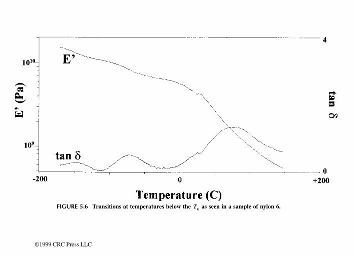
DN7036138Issue 3-2
97
BSS09006: GPRS System Feature Description Radio resource management
Id:0900d80580590b5d
service time is selected and given a turn to send a radio block (provided that no control blocks have to be sent). Also, the latest service time of the selected TBF is incremented by the scheduling step size of the TBF in PCU1. The PCU2 scheduling uses the Bucket Round Robin (BRR) algorithm, and there similar behaviour is obtained using scheduling weight. See parameter conversion in section BSC parameters of System Impact of Priority Class based Quality of Service.
The sizes of the scheduling steps/weight determine the handing out of radio resources. If several TBFs have been allocated to a timeslot, then the higher the scheduling step size or respectively, the lower the scheduling weight of the TBF, the less often it is selected and given a turn.
Scheduling step sizes/weights depend on the priority class of the TBF. In PCU1, each priority class has its own scheduling step size which is operator adjustable. The same applies also to PCU2 scheduling weight which is operator adjustable.
Priorities are also taken into account in allocations of TBFs. The allocation process tries to ensure that better priority TBFs do not gather into the same radio timeslot.
Priority Based Scheduling in BSC is an operating software product and is always active in an active PCU.
To get more detailed information about QoS in Gb, see BSC-SGSN interface descrip-tion; BSS GPRS protocol (BSSGP).
8.5 Channel allocation and schedulingGPRS channels are allocated according to the following rules:
• downlink and uplink are separate resources • multiple mobiles can share one traffic channel, but the traffic channel is dedicated to
one MS at a time — this is referred to as temporary GPRS connection block flow or Temporary Block Flow (TBF) — meaning that one MS is transmitting or receiving at a time; seven uplink and nine downlink TBFs can share the resources of a single timeslot; the uplink and downlink scheduling are independent
• channels allocated to a TBF must be allocated from the same TRX • The traffic channels which would provide the maximum possible (priority based)
capacity, within the restrictions of the multislot class of the mobile, are allocated for a TBF. Exceptions are TBFs for which only one channel is allocated. In PCU2, channel allocation also involves other criteria in case EDA is active. For more infor-mation on EDA, see Overview of Extended Dynamic Allocation.
• the Medium Access (MAC) mode capability of a mobile affects its UL transmission capability (within the Multislot Class restrictions). Dynamic Allocation MAC mode allows an MS to use a maximum of two UL timeslots; Exended Dynamic Allocation (PCU2) allows an MS to use a maximum of four UL timeslots. MAC mode does not affect the DL capability of an MS. For more information, see Packet scheduling.
Temporary Block Flow (TBF) is explained in GPRS radio connection control.
The PCU determines the number of traffic channels that are needed and counts the best throughput for that number of traffic channels. In PCU1 the traffic channel combinations are first compared by QoS load, then by capacity type (additional < default < dedicated) and then by the Packet Associated Control Channel (PACCH) load. The QoS load of a channel is defined as a weighted sum of the TBFs in the channel. The weights used cor-
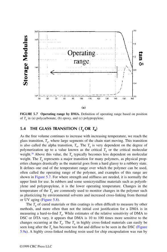
98 DN7036138Issue 3-2
BSS09006: GPRS System Feature Description
Id:0900d80580590b5d
Radio resource management
respond with the scheduling rate of the QoS class of TBFs in the channel. In PCU1 the PACCH load is the number of TBFs using a certain TCH as PACCH. PACCH is defined in more detail in GPRS radio connection control. In PCU2 the PACCH load is monitored by the scheduler and that is used together with the scheduling weights when the relative throughput of the channel combination is estimated. The traffic channel combinations are first compared by relative throughput and then by capacity type (additional < default < dedicated). Furthermore in PCU2, a comparison of estimated throughputs is carried out between DA (max. two slots) and EDA (max. four slots) connections in uplink. For more information, see Functionality of Extended Dynamic Allocation in Extended Dynamic Allocation in BSC.
Higher priority TBFs will get more turns, therefore they will cause more load on the channel.
TBF allocationAfter the BTS has been selected, QoS and TBF type are compared simultaneously. Dif-ferent QoS classes result in different penalties for load comparing. Multiplexed and non-multiplexed TSLs are also prioritised by a penalty value. Among multiplexed TSLs, QoS is the selection criteria. In addition, the PCU monitors PACCH load (in other words sig-nalling load) in TSLs and takes that into account in allocation.
When optimum resources for a mobile are searched for, both UL and DL resources are evaluated and the decision for the allocation is made depending on the amount of effec-tive resources received in both directions. If a mobile is using only one direction (UL or DL), only the resources of the direction used are evaluated. If the mobile being evalu-ated already has an existing TBF in one direction and it requires resources from the other direction, the evaluation of concurrent resources received is first done for the adjoining allocation beside existing allocation and then for different concurrent realloca-tions, where existing TBF is reallocated from its current allocation. In PCU2, however, no preference is given to adjoining allocations when concurrent TBF is being created.
Channel combination in concurrent allocation is determined from operator modifiable parameters CHA_CONC_UL_FAVOR_DIR and CHA_CONC_DL_FAVOR_DIR. If DL TBF exists and UL TBF is allocated as concurrent, CHA_CONC_UL_FAVOR_DIR defines the direction that should be preferred in allocation. Respectively, when allocating DL TBF as concurrent, CHA_CONC_DL_FAVOR_DIR defines the preferred direction. These parameters have three values - favour UL, favour DL and share resources - which result in different emphasis in resource division between UL and DL.
During concurrent TBFs the PCU monitors the traffic, and PCU uses reallocations to modify the timeslot configuration to give preference to the direction with more traffic. Preferred direction takes place only with certain multislot classes that can have different channel combinations, for example 3+1 or 2+2 (DL+UL). If effective resources received in the adjoining allocation are the same as with concurrent reallocation, the adjoining allocation is preferred. In the evaluation of the resources, dedicated and default territory areas are preferred, so if similar resources are found from the additional and default ter-ritory, resources from the default area will be allocated.
Example: The GPRS territory consists of three channels, and an MS of multislot class 4 has a downlink TBF of three timeslots (performing FTP for example) and also uses an uplink TBF of one timeslot to acknowledge the received data (Note that the UL TBF is not always present as it is not always needed). A second mobile of multislot class 4 requests UL resources. These will be allocated to it and the optimum resources are evaluated for

DN7036138Issue 3-2
99
BSS09006: GPRS System Feature Description Radio resource management
Id:0900d80580590b5d
the UL direction only. As a result, the second MS will get its UL resource from a channel that is not used by the first mobile.
Example: Continuing from the previous example, downlink resources are needed for the second mobile. Available resources are evaluated for both directions and the allocation is made in such a way that optimum resources are used in both directions. Now the allocation depends on the resource usage of MS1 in both UL and DL directions.
1. A concurrent allocation for the DL TBF is made for MS2 if MS1 has an UL TBF in use when the DL TBF of MS2 is allocated. The adjoining allocation is made, because the reallocation does not provide any better resources for MS2 in this phase.
As a result, MS1 has the resources of 3 effective timeslots (the total sum of UL and DL resources) and MS2 has the resources of 2 effective timeslots. If MS2 had been allocated in the same way as MS1 (with re-allocation), it would have resulted in both MSS having only 2 effective timeslots (the total sum of UL and DL resources). MS2 does not receive the maximum number of timeslots in the DL direction in this phase, but it will receive them later, when the territory upgrade has been completed.In case of PCU2, the allocation is made according to multislot class capabilities. In other words, adjoining allocation with fewer channels that multislot class allows is not made. If the favoured direction is set to favor DL, 3+1 allocation is reserved for MS2. As a result, MS2 is allocated similarly to MS1.
In case of PCU, if the favoured direction is UL, 2+2 allocation is made.
TSL 0 1 2 3 4 5 6 7
DEF DEF DEF
UL MS1 MS2
DL MS1 MS1 MS1
TSL 0 1 2 3 4 5 6 7
DEF DEF DEF
UL MS1 MS2
DL MS1 MS1
MS2
MS1
MS2
TSL 0 1 2 3 4 5 6 7
DEF DEF DEF
UL MS1
MS2
DL MS1
MS2
MS1
MS2
MS1
MS2
TSL 0 1 2 3 4 5 6 7
DEF DEF DEF
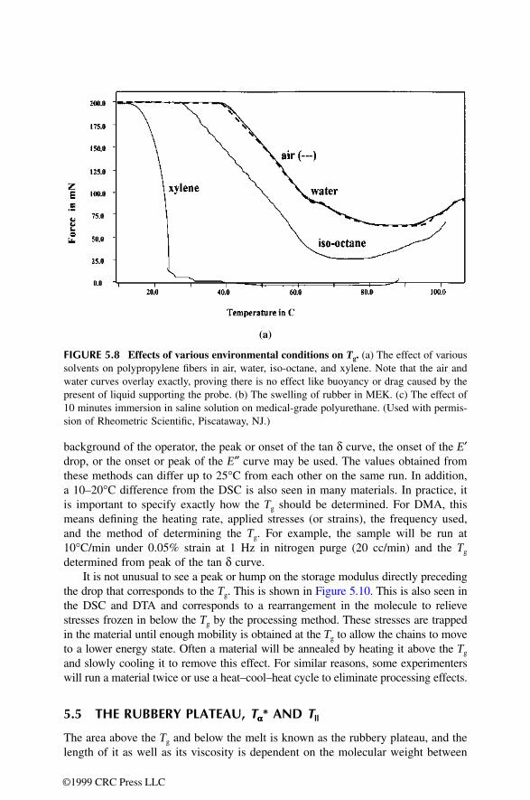
100 DN7036138Issue 3-2
BSS09006: GPRS System Feature Description
Id:0900d80580590b5d
Radio resource management
2. DL resources for MS2 are given with reallocation if MS1 does not have a UL TBF in use when the DL TBF of MS2 is allocated. The reallocation is made, because better resources are achieved with it.
In this allocation, MS1 has the resources of 1.5 effective timeslots (the total sum of UL and DL resources) and MS2 has the resources of 2.5 effective timeslots.Then the PCU would request a territory upgrade according to the rules explained in the section additional GPRS territory upgrade (in case a, two channels will be requested and in case b, three channels will be requested).
Example: Continuing from the previous example, the PCU has received the additional capacity it has requested and the reallocation of the TBF(s) will be made. As a result, the following allocations will be made:
1. Both mobiles will get 2.5 timeslots in the DL direction and 1 timeslot in the UL direc-tion.
2. Both mobiles will get 3 timeslots in the DL direction and 1 timeslot in the UL direction.
After the TBF is created in a BTSWhen a GPRS TBF is in a multiplexed TSL, PCU1 will constantly check:
1. if the channel is multiplexed2. if it is the only GPRS TBF in the TSL thus causing multiplexing
UL MS1
MS2
MS2
DL MS1 MS1
MS2
MS1
MS2
TSL 0 1 2 3 4 5 6 7
DEF DEF DEF
UL MS2
DL MS1
MS2
MS1
MS2
MS1
MS2
TSL 0 1 2 3 4 5 6 7
ADD ADD DEF DEF DEF
UL MS2 MS1
DL MS2 MS2 MS1
MS2
MS1 MS1
TSL 0 1 2 3 4 5 6 7
ADD ADD ADD DEF DEF DEF
UL MS2 MS1
DL MS2 MS2 MS2 MS1 MS1 MS1

DN7036138Issue 3-2
101
BSS09006: GPRS System Feature Description Radio resource management
Id:0900d80580590b5d
3. if there are multiplexed channels where it is allowed to reallocate
In PCU2, allocation is done to achieve the highest possible relative throughput. Conse-quently, the above mentioned checks do not apply since there is no attempt to remove multiplexing and USF Granularity 4 is used.
In addition, PCU constantly checks if reallocation should take place to achieve better relative capacity. Reallocation check interval is determined by operator modifiable parameter TBF_LOAD_GUARD_THRSHLD. The parameter defines reallocation check interval for a TBF in block periods.
The PCU will request for more additional channels, if a GPRS territory contains less channels than what could be allocated to a mobile according to its multislot class. These additional channels will be requested only if all GPRS default channels are already in the GPRS territory. The maximum number of GPRS channels is limited by CMAX.
When ensuring the best quality and speed for end-users, planning may not rely on addi-tional channels in the dimensioning of the GPRS territory. The use of additional channels is less efficient compared to the default channels. The reason for this is that the additional channels (territory upgrade) are always requested from circuit-switched (CS) territory and there is always some delay before the channel is moved to the GPRS territory. For example, there can be a CS call in the timeslot, which is to be moved to the GPRS territory, and intracell handover is needed before the territory upgrade can be completed.
Additional channels are taken into CS use whenever more channels are needed on the CS side. The need for additional GPRS channels is always checked when an existing TBF is terminated. The PCU will request the removal of additional channels, if the average TBF/TSL is less than 0.5 (average TBF/TSL<0.5). The target in the downgrade is to achieve an average TBF/TSL equal of 1.
Packet schedulingUplink and downlink scheduling are independent of each other. The PCU can assign multiple MSS to the same uplink traffic channels. ETSI specifications allow the schedul-ing of uplink transmission turns to be done by two different Medium Access Control (MAC) modes: Dynamic Allocation (DA) and Extended Dynamic Allocation (EDA). The BSC releases from S9 onwards support Dynamic Allocation, and releases from S12 onwards also support Extended Dynamic Allocation (PCU2 only).
In DA and EDA, the BSC gives the MS a USF value for each assigned traffic channel in the assignment message. The MS monitors the downlink Radio Link Control (RLC) blocks on the traffic channels it has been assigned. Whenever the MS finds the USF value in the downlink RLC block, it may send an uplink RLC block in the corresponding uplink frame. The scheduling of the RLC data block in each timeslot is independent of other timeslots. DA allows an MS to use a maximum of two timeslots in UL. Radio Link Control is defined in more detail in GPRS radio connection control.
Figure 22 Dynamic Allocation MAC mode0 1 2 3 4 5 6 7
0 1 2 3 4 5 6 7
T T
USF USF

102 DN7036138Issue 3-2
BSS09006: GPRS System Feature Description
Id:0900d80580590b5d
Radio resource management
EDA allows an MS to use more than two uplink timeslot by removing the need of detect-ing USFs separately for each assigned traffic channel: a received USF gives the MS a permission to send, during the next transmission turn, on the corresponding UL channel and on all the following channels of the UL TBF.
Figure 23 Extended Dynamic Allocation MAC mode
Scheduling in PCU1 is based on a kind of weighted round robin (WRR) method, which means that a higher priority (QoS) Temporary Block Flow (TBF) gets a bigger share of the PDTCHs allocated for it than a lower priority TBF.
Scheduling in PCU2 is based on a Bucket Round Robin (BRR) algorithm. USF granu-larity 4 is only used with DA, not EDA. The main difference to PCU1 WRR algorithm implementation is that BRR distributes transmission turns per MS and not per TCH as WRR in PCU1 implementation. Both WRR and BRR distribute capacity according to connection specific scheduling weights.
See Quality of service for more information on adjusting weight in priority based QoS.
Extended Uplink TBF modeExtended UL TBF mode is an optional functionality.
If the MS supports Extended UL TBF Mode (indicated in MS RAC), the normal uplink release is delayed. The delay time is operator adjustable with parameter UL_TBF_REL_DELAY_EXT. During delay time MS is in extended mode. In extended mode network schedules USFs to MS with lower scheduling rate. If MS in extended mode has data to send data it returns to normal mode. For more information, see Data transfer.
Scheduling in extended mode for an uplink TBF is based on operator modifiable param-eters UL_TBF_SCHED_RATE_EXT in PCU1 and POLLING_INTERVAL in PCU2. In PCU1, UL_TBF_SCHED_RATE_EXT defines the next block period when a TBF in extended mode is given a transmission turn. However, a TBF in extended mode cannot have better residual capacity than it would in normal mode. In PCU2, POLLING_INTERVAL defines the time in block periods that TBF in extended state cannot have transmission time. After POLLING_INTERVAL is elapsed, TBF is returned to scheduling and once it is scheduled it is restricted again unless it is returned to normal mode.
Dynamic Scheduling for Extended UL TBF ModeIn PCU2, Dynamic Scheduling for Extended UL TBF Mode optimises the scheduling algorithm applied to mobile stations in extended uplink TBF mode (EUTM). When any of the uplink TSLs which can be used for polling an MS in EUTM accommodates more than one UL TBF, the POLLING_INTERVAL parameter defines the frequency of UL transmission turns scheduled for the MS in EUTM. When none of the uplink TSLs which can be used for polling an MS in EUTM accommodates more than one UL TBF, the POLLING_INTERVAL_BG_LOW parameter defines the frequency of UL transmission turns scheduled for the MS in EUTM. This method helps to improve the RTT perfor-
0 1 2 3 4 5 6 7
USF
0 1 2 3 4 5 6 7
T T T

DN7036138Issue 3-2
103
BSS09006: GPRS System Feature Description Radio resource management
Id:0900d80580590b5d
mance for MSS in EUTM under light or moderate traffic density without affecting adversely the radio throughput of other users.
8.6 Quality ControlThe purpose of Quality Control is to monitor and detect degradation periods in service quality, and to perform corrective actions to remove the service degradation. The possible actions include TBF reallocation and Network-Controlled Cell Re-selection. Monitoring of degradation in service quality includes BLER and bitrate per radioblock monitoring.
The PCU monitors bitrate per radio block for each TBF in RLC ACK mode, for UL and DL separately. When the PCU sends or receives a radio block, it updates the number of bits transmitted/received in the radio block. The PCU ignores LLC dummy blocks in this calculation. For the retransmissions, the PCU shall calculate the number of bits trans-mitted as zero.
The PCU calculates the bitrate per radio block value and checks it against the corre-sponding threshold value. The threshold values are operator parameters and there is a separate value for UL and DL: QC GPRS DL RLC ack throughput threshold (QGDRT), QC GPRS UL RLC ack throughput threshold (QGURT) . If the cal-culated value is below threshold, degradation duration time is increased. The PCU monitors the bitrate per radio block degradation duration counter. If the counter is larger than predefined triggering levels, the corresponding corrective action is performed.
The PCU monitors also RLC Block Error Ratio (BLER) for each TBF. The BLER value shall be checked against the required maximum BLER. In PCU1, maximum BLER is defined by operator parameter maximum BLER in acknowledged mode (BLA) or maximum BLER in unacknowledged mode (BLU), depending on the RLC mode of the TBF. In PCU2, maximum BLER is defined by operator parameters PFC ACK BLER limit (ABL1) and PFC UNACK BLER limit (UBL1). If BLER is above maximum, degradation duration time is increased and if the counter is larger than pre-defined triggering levels, the corresponding corrective action is performed.
When any of the degradation duration counters monitored by the PCU gets larger than a predefined action trigger threshold, the PCU shall perform a corresponding corrective action. Each action shall be triggered only once for a TBF in PCU. For example, if real-location is already done, the next action to be performed is Network-Controlled Cell Re-selection (NCCR), triggered when a degradation duration counter exceeds the NCCR trigger threshold. The flags of already performed actions are cleared when the degrada-tion ends, that is when all the degradation duration counters are cleared.
The action trigger thresholds are expressed in block periods and the values can be set by operator (see parameter QC Action Trigger Threshold). It is possible to change the order of different actions by modifying the action trigger threshold values. If two or more actions are set to the same threshold value, the order of actions is first real-location and then NCCR. Although possible, it is not recommended to set the values very close to each other, for example reallocation 100, NCCR 101. Otherwise, there is no time to execute the triggered action before the next is already triggered. The default action trigger threshold values are shown below.

104 DN7036138Issue 3-2
BSS09006: GPRS System Feature Description
Id:0900d80580590b5d
Radio resource management
(*) Applicable if NCCR is activated.
8.7 MS Multislot Power Reduction (PCU2)When multiple timeslots have been assigned to an uplink GPRS radio connection (UL TBF), the mobile station may reduce its transmission power as a function of the number of these timeslots: the more UL timeslots assigned, the larger the transmission power reduction applicable. This power reduction helps the MS to meet radiation regulations and to avoid heating problems.
Every mobile station (Rel 5 or later) conforms to one of four standardised Multislot Power Profiles (0-3), which determine the maximum output power supported by an MS for different UL TBF configurations. An MS of Multislot Power Profile 3 does not apply power reduction to connections of four UL timeslots and less, while the amount of appli-cable reduction increases with each lower Power Profile.
The effect of Multislot Power Reduction needs to be observed in radio resource alloca-tion because the output power of an MS contributes to radio path quality, and conse-quently affects both the choice of the channel coding scheme to be used (CS1-CS4) and the achievable throughput per timeslot within the chosen scheme. In other words, large power reduction leads to poorer radio path quality, which in turn decreases throughput per timeslot both by necessitating robust channel coding and by increasing the number of transmission errors and retransmissions.
In resource allocation, the effect of power reduction is observed by using UL signal quality measurements by the BTS to determine the maximum number of UL timeslots that can be assigned to the MS and still keep the signal quality at an acceptable level in spite of the entailing transmission power reduction.
Multislot power reduction is applicable to all multislot UL connections. If EDA is enabled, up to four timeslots may be assigned to an UL TBF. If EDA is not enabled, up to two timeslots may be assigned in UL.
UL signal quality and the maximum number of timeslotsIf the MS UL signal quality (GMSK Mean BEP or RX Quality measured by the BTS) is known during radio resource allocation, which is normally the case during two-phase access, the PCU uses this information to determine the maximum number of UL timeslots that may be allocated for the MS. The PCU uses the signal quality measure-ment that is available, but typically Mean BEP is used if Dynamic Abis is supported, and RX Quality is used in other cases.
The operator can define the signal quality limits for different UL timeslot configurations by modifying the Mean BEP Limit and RX Quality Limit parameters. In determin-ing these limits, the appropriate signal quality - as typically required by applications used in the network - must be considered together with the power reduction characteristics of different mobile stations. The limits should be set so that the signal quality remains
Action Block periods
Reallocation 25
NCCR (*) 100

DN7036138Issue 3-2
105
BSS09006: GPRS System Feature Description Radio resource management
Id:0900d80580590b5d
acceptable even when the MS applies maximum power reduction. The following tables define the default values for the two signal quality limits (for Rel 5 mobiles and later).
For instance, three UL timeslots may be assigned to a Multislot Power Profile 1 MS if the measured GMSK Mean BEP value is 25 or higher.
For instance, three UL timeslots may be assigned to a Multislot Power Profile 1 MS if the measured RX Quality is three or lower.
If no Multislot Power Profile has been defined for an MS (Rel 4 or earlier) or the Profile is not known by the PCU for some other reason, the PCU handles the MS according to Power Profile 0.
When an UL TBF is reallocated to another BTS, where the mobile station specific GMSK Mean BEP and RX Quality measurements are not available for the MS, the maximum number of timeslots that can be assigned to the reallocated connection is determined on the basis of the general RX level in the new BTS. This is done by checking what number of timeslots - considering the Multislot Power Profile of the MS - would allow at least the same average RX level to be achieved under the new BTS as under the old one.
8.8 Error situations in GPRS connectionsSynchronisation errorsWhen the PCU detects a synchronisation error between itself and the BTS, the BSC downgrades the related channels from GPRS use. The BSC upgrades the radio timeslots back to GPRS use after a guard period.
MAX Number of UL TSLs
MS Multislot Power Profile 0
MS Multislot Power Profile 1
MS Multislot Power Profile 2
MS Multislot Power Profile 3
1 — — — —
2 21 20 — —
3 26 25 24 —
4 30 30 29 —
Table 38 GMSK Mean BEP Limit for UL
MAX Number of UL TSLs
MS Multislot Power Profile 0
MS Multislot Power Profile 1
MS Multislot Power Profile 2
MS Multislot Power Profile 3
1 — — — —
2 5 5 — —
3 3 3 3 —
4 1 1 2 —
Table 39 RX Quality Limit for UL

106 DN7036138Issue 3-2
BSS09006: GPRS System Feature Description
Id:0900d80580590b5d
Radio resource management
Traffic channel activation failuresThe BSC sets the alarm TRAFFIC CHANNEL ACTIVATION FAILURE 7725 if the Abis synchronisation for an GPRS traffic channel repeatedly fails. The alarm is automatically cancelled when the synchronisation succeeds and the channel is taken back into GPRS use.
GPRS Inactivity (Sleeping BTSs)The BSC sets the alarm NO (E)GPRS TRANSACTIONS IN BTS 7789 if there have been no normal TBF releases within the supervision period in a BTS where this alarm is enabled, although there have been allocation TBF attempts.
To enable this alarm functionality in the BSC, you define the triggering criteria, length of the supervision period and traffic threshold. The recommended triggering criteria is the lack of normal TBF releases both in UL and DL, but you may choose to monitor only one of the directions. The length of the supervision period shall be defined according to esti-mated traffic density, recommended values ranging from 15 minutes (default) to 60 minutes. Traffic threshold means the required number of TBF allocation attempts per hour, to ensure that the alarm is not raised due to low traffic volume. Default value for traffic threshold is 10 TBF allocation attempts per hour.
The BSC level configuration of this alarm is done by modifying the following parameters with the MML command EEJ:
EGIC=<EGPRS Inactivity Alarm criteria> 0x00: Alarm disabled on BSC Level (default) 0x01: No normal UL TBF releases 0x02: No normal DL TBF releases 0x03: No normal UL TBF releases and no normal DL TBF releases (recommended)
IEPH=<Required number of TBF allocation attempts per hour> Default: 10 Range: 0 ... 255
SPL=<Supervision period in minutes> Default: 15 minutes Range: 0 ... 1440 minutes
The alarm also needs to be enabled on the BTSs, which will be monitored. This is done by configuring the related BTS level parameters. Although the supervision period length is common for all BTSs within a BSC, the supervision periods (weekdays and hours) can be defined separately for each BTS.
The BTS level configuration of this alarm is done by modifying the following parameters with the MML command EQV:
EAW = <(E)GPRS Inactivity Alarm weekdays (bitmask)> Default: 00000000b (alarm disabled in BTS) Examples: 01000000 (Monday) 00100000 (Tuesday) 01111100 (Monday thru Friday) 01111111 (Every day)
EAS = <(E)GPRS Inactivity Alarm start time (hours-minutes)> Default: 08-00 Range: 00-00 ... 23-45

DN7036138Issue 3-2
107
BSS09006: GPRS System Feature Description Radio resource management
Id:0900d80580590b5d
EAE = <(E)GPRS Inactivity Alarm end time (hours-minutes)> Default: 18-00 Range: 00-00 ... 23-45
The alarm is set if the criteria is met at the end of the supervision period.The criteria is that no normal TBF releases have been detected within a 15 minute (default) period during the hours when the alarm is active on the given weekdays, and there have been at least the required number of TBF allocation attempts.
The alarm is cancelled if a normal TBF release is detected within the subsequent super-vision periods. Note that the cancellation is not dependent on the setting criteria, but a normal TBF release in either direction cancels the alarm.
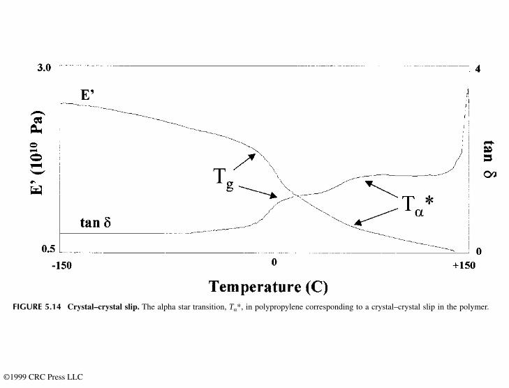
108 DN7036138Issue 3-2
BSS09006: GPRS System Feature Description
Id:0900d80580590b60
GPRS radio connection control
9 GPRS radio connection controlRadio channel usage when GPRS is in use is discussed in this section. The GPRS radio connection establishment (TBF establishment) and data transfer are described from the point of view of a mobile terminating (MT) and mobile originating (MO) GPRS TBF. Paging is described in a section of its own. This section describes the BSC's functions in relation to suspend and resume, flush, coding scheme selection, as well as traffic administration and power control in GPRS. Cell selection and re-selection are also defined.
9.1 Radio channel usageETSI specifications (05.02) define the possibility to use dedicated broadcast and common control channels for GPRS.
System information messages on BCCHThe support of GPRS is indicated in a SYSTEM_INFORMATION_TYPE_3 message. GPRS-specific cell parameters are sent to the MS in a SYSTEM_INFORMATION_TYPE_13 message.
For more information refer to GSM Specification (04.18).
Common Control Channel (CCCH) signallingThe Common Control Channel (CCCH) signalling is used for paging and uplink and downlink temporary block flow (TBF) setup.
GPRS paging is made on the Paging Channel (PCH). The MS initiates uplink TBF estab-lishment on the Random Access Channel (RACH). The network responds to the MS on the Access Grant Channel (AGCH). Network-initiated TBF establishment is done on the AGCH.
Packet Data Traffic Channel (PDTCHs)The Packet Data Traffic Channel (PDTCH) is a channel allocated for data transfer. It is temporarily dedicated to one MS. In multislot operation, one MS may use multiple PDTCHs in parallel for individual packet transfer. All PDTCHs are uni-directional, either uplink (PDTCH/U) for a mobile originated packet transfer or downlink (PDTCH/D) for a mobile terminated packet transfer. PDTCH/U and PDTCH/D can be assigned to an MS simultaneously. In the Nokia Siemens Networks implementation, traffic channels belonging to a GPRS territory are PDTCHs and traffic channels belonging to circuit switched territory are TCHs. The PCU uses each radio timeslot which the BSC has allo-cated for the GPRS territory, as one PDTCH. GPRS territories are described in Radio resource management.
Packet Associated Control Channel (PACCH)The Packet Associated Control Channel (PACCH) conveys signalling information related to a given MS. The signalling information includes, for example, acknowledge-ments and resource assignment and reassignment messages. One PACCH is associ-ated to one or several traffic channels that are assigned to one MS. PACCH is a bi-directional channel. It can be allocated both on both uplink and downlink regardless of whether the corresponding traffic channel assignment is for uplink or downlink. Assigned traffic channels are used for PACCH in the direction the data is sent. In the
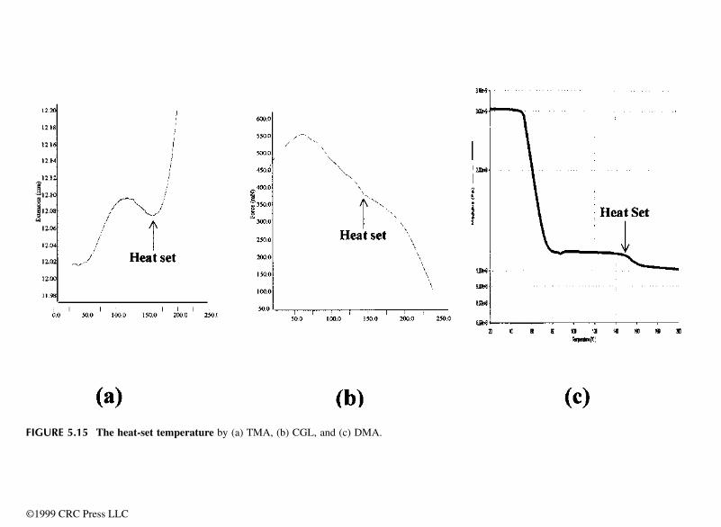
DN7036138Issue 3-2
109
BSS09006: GPRS System Feature Description GPRS radio connection control
Id:0900d80580590b60
opposite direction the MS multislot capability has to be taken into account when allocat-ing the PACCH.
For an overview of GPRS, see GPRS.
9.2 Data Transfer Protocols and ConnectionsTemporary Block Flow (TBF)Temporary Block Flow (TBF) is a physical connection used by two radio resource entities to support the unidirectional transfer of Logical Link Control (LLC) PDUs on packet data physical channels. The TBF is allocated radio resources on one or more PDTCHs and comprises a number of RLC/MAC blocks carrying one or more LLC PDUs. A TBF is identified by a Temporary Flow Identity (TFI) and maintained only for the duration of the data transfer.
Logical Link Control (LLC) and Radio Link Control (RLC)The Logical Link Control (LLC) layer provides a highly reliable ciphered logical link. LLC is independent of the underlying radio interface protocols in order to allow introduction of alternative GPRS radio solutions with minimum changes to the NSS. LLC PDUs are sent between the MS and the SGSN.
The Radio Link Control (RLC) function provides a radio-solution-dependent reliable link. RLC blocks are sent between the MS and the BSC (PCU). There are two RLC modes: acknowledged and unacknowledged mode. The latter does not have retransmission.
In downlink data transmission, the PCU receives LLC PDUs from the SGSN, segments them to the RLC blocks and sends the RLC blocks to the MS. The LLC PDU is buffered in the PCU until it has been sent to the MS or discarded.
In uplink data transmission, the PCU receives the RLC data blocks from the MS and reassembles them into LLC PDUs. When the LLC PDU is ready, the PCU sends it to the SGSN and releases it from the PCU buffer. The LLC PDUs have to be sent to the SGSN in the order they were transmitted by the MS.
9.3 PagingThe network may provide co-ordination of paging for circuit switched services and GPRS depending on the network operation modes supported.
Network operation modesThe BSC supports network operation modes I and II. Mode I requires Gs interface between the SGSN and MSC/HLR.
In mode II circuit switched paging messages are transferred through the A interface from the MSC to the BSC. In mode I circuit switched paging messages are routed through the Gb interface for GPRS-attached mobiles. GPRS pages always come from the SGSN through the Gb interface.
The network operation mode is indicated as system information to mobiles, and it must be the same in each cell of a Routing Area. Based on the provided mode, an MS can choose (according to its capabilities) whether it attaches to GPRS services or to non-GPRS services, or to both.

110 DN7036138Issue 3-2
BSS09006: GPRS System Feature Description
Id:0900d80580590b60
GPRS radio connection control
GPRS pagingThe SGSN initiates the GPRS paging process. It sends one or more PAGING_PS_PDUs messages to the BSC (PCU). These PDUs contain the information elements necessary for the BSS to initiate paging for an MS within a group of cells at an appropriate time. The BSC translates the incoming GPRS and circuit switched paging messages into one corresponding Abis paging message per cell. A GPRS paging message is sent only to cells that support GPRS services.
The paging area indicates the cells within which the BSC pages the MS and they can be:
• all cells within the BSC • all cells of the BSC within one Location Area • all cells of the BSC within one Routing Area • one cell (identified with a BSSGP virtual connection identifier (BVCI)).
A Routing Area, a Location Area, or a BSC area is associated with one or more NSEIs (PCUs). If the cells in which to page the MS are served by several NSEIs, then the SGSN sends one paging message to each of these NSEIs.
The SGSN indicates the MS's IMSI and DRX parameters, which enables the BSS to derive the paging group. If the SGSN provides a P-TMSI, then the BSC uses it to address the MS. Otherwise IMSI is used to address the MS.
In GPRS paging the BSS forwards the PACKET_PAGING_REQUEST message from the SGSN to the MS on the CCCH(s). The MS's paging response to the SGSN is handled in the PCU as any other uplink TBF.
For more information, refer to BSC-SGSN Interface Specification, BSS GPRS Protocol (BSSGP).
☞ RA0 is a routing area for cells that do not support GPRS.
☞ Gs interface is obligatory in order to support CS paging.
Circuit switched paging via GPRS in network operation mode IIn order to initiate circuit-switched transmission between the MSC and the MS, the SGSN sends one or more PAGING CS PDUs to the BSC. These PDUs contain the infor-mation elements necessary for the BSS to initiate paging for an MS within a group of cells. The paging area is the same as in GPRS paging.
The SGSN indicates the MS's IMSI and DRX parameters, which enable the BSS to derive the paging group. If the SGSN provides the TMSI, then the BSC does not use the IMSI to address the MS. If a radio context identified by the TLLI exists within the BSS, then the paging message is directly sent to the MS on PACCH. If no radio context iden-
Mode Circuit Paging Channel
GPRS Paging Channel
Gb interface Paging co- ordi-nation
I CCCH CCCH Yes Yes
I Packet Data Channel
N/A Yes Yes
II CCCH CCCH No No
Table 40 Supported Network Operation Modes
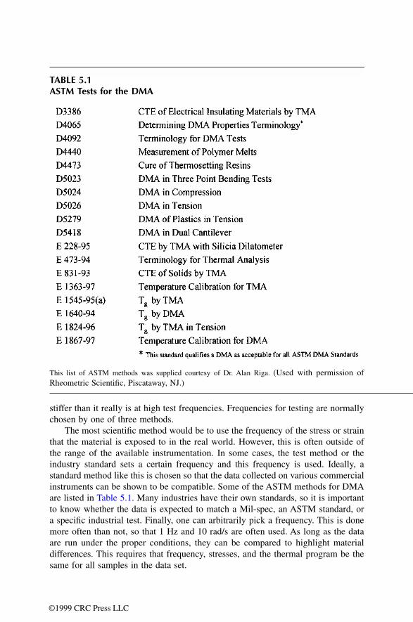
DN7036138Issue 3-2
111
BSS09006: GPRS System Feature Description GPRS radio connection control
Id:0900d80580590b60
tified by the TLLI exists within the BSS, then the TMSI is used to address the MS. Oth-erwise IMSI is used to address the MS.
After the paging procedure, the circuit switched connection is set up as usual as described in Basic Call.
If within the SGSN area there are cells that do not support GPRS services, the cells are grouped under a 'null RA' (RA0). RA0 covers all the cells in the indicated paging area that do not support GPRS services. For example, if the SGSN indicates to the BSC to initiate paging for an MS within a Routing Area the BSC sends one circuit switched paging message to all cells in the Routing Area and one message to all the cells in RA0. The RA0 in this case is all the cells that do not support GPRS services in a Location Area derived from the Routing Area.
For more details about the paging message contents, refer to BSC-SGSN Interface Specification, BSS GPRS Protocol (BSSGP).
9.4 Mobile terminated TBF (GPRS)When the SGSN knows the location of the MS, it can send LLC PDUs to the correct PCU. Each LLC PDU is encapsulated in one DL-UNITDATA PDU. The SGSN indicates the cell identification in every DL-UNITDATA PDU. For more details about the downlink data message contents, refer to BSC-SGSN Interface Specification, BSS GPRS Protocol (BSSGP).
The PCU allocates one or more PDTCHs for the TBF, and indicates it and the TFI to the MS in the assignment message. The TBF establishment is done in one of the following ways:
• on PACCH; used when a concurrent UL TBF exists or when the timer T3192 is running in the MS
• on CCCH; used when there is no concurrent UL TBF, and T3192 is not running
These alternatives are described in the following subchapters.
Downlink TBF establishment on CCCHThe PCU allocates one PDTCH for the TBF, and sends an IMMEDIATE_ASSIGNMENT message to the MS. The possible multislot allocation is done later and indicated to the MS by a reallocation message.
When the MS is ready to receive on PACCH, the PCU sends a PACKET_POLLING_REQUEST message to the MS and requests an acknowledgement. This is done in order to determine the initial Timing Advance for the MS. If the channel configuration to be allocated for the downlink TBF consists of only one channel already assigned to the MS, the PCU sends the PACKET_POWER_CONTROL/TIMING_ADVANCE message to the MS to indicate the Timing Advance value.
When multiple PDTCHs are allocated to the MS, the MS GPRS multislot class must be taken into account. The MS GPRS multislot class is part of the MS Radio Access Capa-bility IE, which is included in the DL-UNITDATA_PDU message. The PCU sends the PACKET_DOWNLINK_ASSIGNMENT message, and gives the whole configuration together with the Timing Advance value to the MS.
In case there are no radio resources for the new TBF, the LLC PDU is discarded and the BSC sends a LLC-DISCARD message to the SGSN. The assignment procedure is

112 DN7036138Issue 3-2
BSS09006: GPRS System Feature Description
Id:0900d80580590b60
GPRS radio connection control
guarded with two timers, one for resending the IMMEDIATE_ASSIGNMENT message and one for aborting the establishment.
Downlink TBF establishment when an uplink TBF existsDownlink TBF establishment when an uplink TBF exists follows the same principles as uplink TBF establishment when a downlink TBF exists. This is discussed more at the end of Mobile originated TBF.
The establishment is done with a PACKET_DOWNLINK_ASSIGNMENT or PACKET_TIMESLOT_RECONFIGURE message. The TBF mode is always the same as the mode of the existing UL TBF.
Downlink TBF establishment when timer T3192 is running and no UL TBF existsWhen the DL TBF is released, the MS starts the timer T3192 and continues monitoring the PACCH of the released TBF until T3192 expires. During the timer T3192 the PCU makes the establishment of a new DL TBF by sending a PACKET_DOWNLINK_ASSIGNMENT on the PACCH of the 'old' DL TBF.
MS-specific flow controlMobile specific flow control is part of the QoS solution in the PCU. It works together with the SGSN to provide a steady data flow to the mobile from the network. Mobile specific flow control also ensures that if an MS has better QoS, and therefore better transmission rate in radio interface (more air time), it will also get more data from the SGSN. It is also an effective countermeasure against buffer overflows in the PCU. Mobile-specific flow control is done for every MS that has a downlink TBF. There is no uplink flow control.
Data transferDuring the actual data transfer, the MS recognises the transmitted Radio Link Control (RLC) blocks based on the TFI, which is included in every RLC block header. Each TBF has a transmit window, which is the maximum number of unacknowledged RLC blocks at a time. The window size is 64 blocks in GPRS mode.
The PCU can request the MS to send an PACKET_DOWNLINK_ACK/NACK message by setting a polling flag to the RLC data block header. The PCU can send further RLC data blocks along with the acknowledgement procedure. If the PCU does not receive the PACKET_DOWNLINK_ACK/NACK message when polled, it increments a counter. After the counter reaches its maximum value of 8, the BSC considers the MS as lost, releases the downlink TBF and discards the LLC PDU from the PCU buffer. The BSC signals this to the SGSN by setting the Radio Cause information element (IE) value to 'radio contact lost with MS'. This indicates to the SGSN that attempts to communicate between the MS and the SGSN via the cell should be suspended or abandoned. The BSC thus recom-mends the SGSN to stop sending LLC PDUs for the MS to the cell.
The counter is reset after each correctly received PACKET_DOWNLINK_ACK/NACK.
The PCU can change the downlink PDTCH configuration whenever needed by sending the MS_PACKET_DOWNLINK_ASSIGNMENT or PACKET_TIMESLOT_RECONFIGURE message. The reasons for this reallocation may be a GPRS territory downgrade, uplink TBF establishment, or a change of requirements of the SGSN.
If reallocation is impossible in the case of GPRS territory downgrade, the PCU may release channels with a PDCH_RELEASE message.
The normal downlink TBF release is initiated by the PCU by setting a Final Block Indi-cator (FBI) bit in the last RLC block header. There may still be some retransmission after
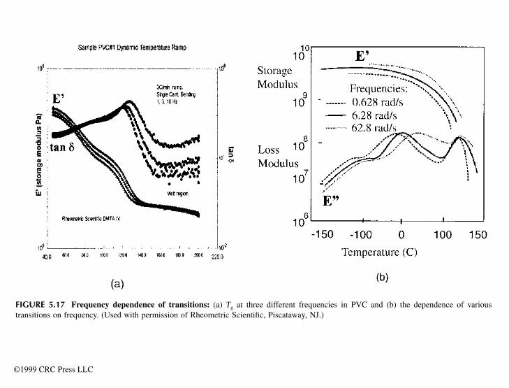
DN7036138Issue 3-2
113
BSS09006: GPRS System Feature Description GPRS radio connection control
Id:0900d80580590b60
this, but the PCU releases the TBF and removes the LLC PDU from the PCU buffer when the MS sends the PACKET_DOWNLINK_ACK/NACK message with the Final Ack Indicator bit on.
When the PCU has sent the last buffered LLC PDU to the MS, the PCU delays the release of the TBF (by 1 s by default). If there is no concurrent UL TBF, during the delay time DUMMY LLC PDUs are sent to the MS (with polling), in order to allow the MS to request for a UL TBF. If the PCU receives more data during the delay time, the PCU cancels the delayed release and begins to send RLC data blocks to the MS, in other words the same downlink TBF continues normally.
9.5 Mobile originated TBFWhen the MS wants to send data or upper layer signalling messages to the network, it requests the establishment of an uplink TBF from the BSC. There are the following main alternatives for the TBF establishment:
• on PACCH; used when a concurrent DL TBF exists • on CCCH; used when there is no concurrent DL TBF
Additionally, on CCCH there are different options for TBF establishment, for example one phase access or two phase access, depending on the needs for the data transfer. The PCU may force the MS to make a two phase access, even if the MS requested some other access type, for instance if there is no room for the TBF in the BCCH band.
These alternatives are described in the following subsections.
Random access on CCCHThe MS can send a CHANNEL_REQUEST message on CCCH (RACH).
One phase access on CCCH, GPRSIn a one phase access the MS sends a CHANNEL_REQUEST message with the estab-lishment cause 'one phase access'. The PCU allocates a PDTCH for the request, and informs the MS in the IMMEDIATE_ASSIGNMENT message along with TFI and USF values. The MS sends its TLLI in the first data blocks and the one phase access is fin-alised when the PCU sends the PACKET_UPLINK_ACK/NACK message to the MS con-taining the TLLI (contention resolution).
If the PCU has no PDTCHs to allocate to the MS, it sends an IMMEDIATE_ASSIGNMENT_REJECT message to the MS. One phase access is guarded by a timer in the PCU.
Two phase access on CCCH, GPRSIn a two phase access the MS sends a CHANNEL_REQUEST message with the establish-ment cause 'single block access'. The PCU allocates one uplink block for the request, schedules a certain radio interface TDMA frame number for the block, and informs it to the MS in the IMMEDIATE_ASSIGNMENT message.
The MS then uses the allocated block to send a more accurate request to the PCU with the PACKET_RESOURCE_REQUEST message. The PCU allocates the actual configura-tion for the uplink TBF according to the information received in this message. When multiple PDTCHs are allocated to an MS, the MS GPRS multislot class must be taken into account. The MS GPRS multislot class is a part of the MS Radio Access Capability IE, which is included in the PACKET_RESOURCE_REQUEST message. The PCU indi-

114 DN7036138Issue 3-2
BSS09006: GPRS System Feature Description
Id:0900d80580590b60
GPRS radio connection control
cates the PDTCH configuration, USF value for each PDTCH, and the TFI to the MS in the PACKET_UPLINK_ASSIGNMENT message sent in the same timeslot in which the single block was allocated, but the assigned PDTCH(s) may be elsewhere. The channel allocation in this second phase is independent of the first phase, and if the PCU has no PDTCHs to allocate to the MS, it sends a PACKET_ACCESS_REJECT message to the MS. The second part of the two phase access is guarded with a timer in the PCU.
The two phase access is finalised when the PCU receives the first block on the assigned PDTCH . The MS sends its TLLI in the PACKET_RESOURCE_REQUEST message, and the PCU includes it in the PACKET_UPLINK_ASSIGNMENT message to the MS (conten-tion resolution).
Data transferIn uplink data transfer, the RLC data blocks are collected to the PCU buffer. The TBF has a transmit window, which is the maximum number of unacknowledged RLC blocks. The window size is 64 blocks in GPRS mode.
The PCU can schedule the MS to send further the RLC data blocks along with the acknowledgement procedure. The PCU can at any time send the PACKET_UPLINK_ACK/NACK message to the MS. The PACKET_UPLINK_ACK/NACK message includes a bitmap which tells the correctly received blocks. The PCU can use the PACKET_UPLINK_ACK/NACK message for other purposes too, for example to change the coding scheme, which also affects the frequency of the acknowledgements.
The PCU has a counter to control the MS's ability to send RLC blocks in the frames it has been assigned by the USF values. The counter is always reset when the MS uses the frame it has been assigned to. If the counter reaches its maximum value of 15, the MS is considered lost and therefore the PCU releases the uplink TBF.
The PCU delivers the LLC PDU with a UL-UNITDATA PDU to the SGSN. There is only one LLC PDU per UL-UNITDATA PDU. The underlying network service has to be avail-able for the BSSGP level in order to deliver data to the SGSN. Otherwise the data is dis-carded and a counter is updated.
The PCU can change the uplink PDTCH configuration whenever needed by sending the MS a PACKET_UPLINK_ASSIGNMENT or PACKET_TIMESLOT_RECONFIGURE message. Reasons for reallocation may be a GPRS territory downgrade, downlink TBF establishment, or a change of an MS's requirements.
If reallocation during a downgrade is impossible, the PCU releases channels with a PDCH_RELEASE message to the MS. A normal uplink TBF release is made by count-down, where the MS counts down the last RLC data blocks (15 or less) with the last block numbered 0. There may still be some retransmission, but when the PCU has received all the RLC data blocks correctly, it sends the LLC PDU to the SGSN, and a PACKET_UPLINK_ACK/NACK message with final ack indicator to the MS. The MS responds with a PACKET_CONTROL_ACK message and the PCU releases the TBF.
If the MS supports Extended UL TBF Mode (indicated in MS RAC), the normal uplink release is delayed. Instead of sending a PACKET_UPLINK_ACK/NACK (final ack) imme-diately, the network schedules USF turns to the MS in extended mode, but with a lower rate as normally. For more information on Extended UL TBF Mode, see section Channel allocation and scheduling. The MS sends a PACKET UPLINK DUMMY CONTROL BLOCK in the scheduled block if it has no data to send. If the MS has got new data, it sends an RLC data block, and after that the PCU cancels the delayed TBF release, and the TBF continues with the normal scheduling rate.

DN7036138Issue 3-2
115
BSS09006: GPRS System Feature Description GPRS radio connection control
Id:0900d80580590b60
Even if the MS does not support Extended UL TBF Mode, the PCU may delay the UL TBF release (by 0.5s by default). This is done when there is no concurrent DL TBF for the same MS. The purpose of the delay is to speed up the possibly following DL TBF establishment. No USF turns are scheduled during this delay.
For more details about the uplink data message contents, refer to BSC-SGSN Interface Specification, BSS GPRS Protocol (BSSGP).
Uplink TBF establishment when downlink TBF exists During a downlink TBF the MS can request resources for an uplink TBF by including a Channel Request Description IE in the PACKET_DOWNLINK_ACK/NACK message. The TBF mode of the new UL TBF is always the same as the mode of the existing DL TBF.
If there is no need to change the downlink PDTCH configuration, a PACKET_UPLINK_ASSIGNMENT message from the PCU to the MS contains the uplink PDTCH configuration, USF values for each PDTCH, and TFI.
If the downlink PDTCH configuration is changed, for instance due to MS multislot capa-bility restrictions, the PACKET_TIMESLOT_RECONFIGURE message from the PCU informs the MS of both the uplink and downlink PDTCH configurations, USF values for the uplink PDTCHs, and the uplink and downlink TFIs.
The establishment is ready when the PCU receives the first block on the assigned uplink PDTCHs. This establishment is also guarded by a timer in the PCU.
If the PACKET_UPLINK_ASSIGNMENT message fails, the uplink TBF is released. If the PACKET_TIMESLOT_RECONFIGURE message fails, both downlink and uplink TBFs are released.
9.6 Suspend and resume GPRSThe GPRS suspension procedure enables the network to discontinue GPRS packet flow in the downlink direction. Suspend is referred to as the situation, which occurs when a circuit switched call interrupts a GPRS packet flow and the GPRS connection is thus dis-continued or suspended.
When a mobile station which is IMSI attached for GPRS services enters dedicated mode, and when the MS or network limitations make it unable to handle both dedicated mode and either packet idle mode or packet transfer mode simultaneously (in other words DTM cannot be used), the MS performs the GPRS suspension procedure. The GPRS_SUSPENSION_REQUEST message is an indication to the SGSN not to send downlink data.
The MS initiates the GPRS suspension procedure by sending a message to the BSC. The BSC sends the SUSPEND_PDU message to the SGSN. The message contains the TLLIand the Routing Area of the MS. The SGSN acknowledges with a SUSPEND-ACK PDU message, which contains the TLLI, the Routing Area of the MS, and the Suspend Reference Number. The SGSN typically stops paging for a suspended mobile.
If the SGSN is not able to suspend GPRS services, it sends a negative response to the BSC with the SUSPEND-NACK PDU message. The message contains the TLLI, the Routing Area of the MS and the cause of the negative acknowledgement.
When a GPRS attached MS in an (E)GPRS-capable but non-DTM-capable cell leaves dedicated mode, disconnecting the MS from the MSC, or a DTM-capable MS is handed over from a non-DTM cell to a cell that supports DTM, the reason for the suspension dis-
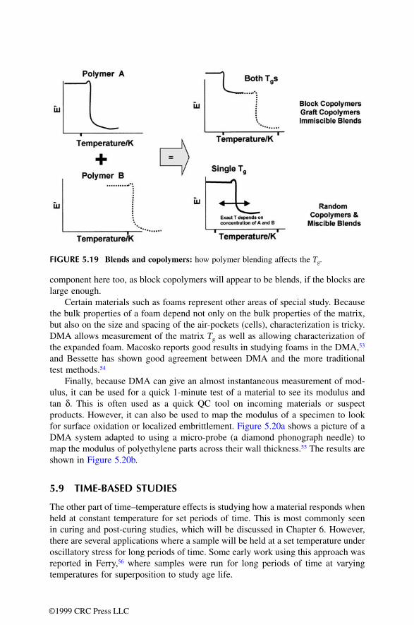
116 DN7036138Issue 3-2
BSS09006: GPRS System Feature Description
Id:0900d80580590b60
GPRS radio connection control
appears. In this case, the BSC either instructs the MS to initiate the Routing Area Update procedure or signals to the SGSN that the MS's GPRS service shall be resumed.
If a DTM-capable MS is handed over from a non-DTM cell to a cell that supports DTM during a dedicated connection, the MS shall perform the Routing Area Update proce-dure to resume GPRS services in the new cell. The MS starts the Routing Area Update procedure after detecting the DTM service in the cell.
If the suspension procedure has been successfully completed and the reason for the suspension is still valid, for instance a DTM-capable MS has not been handed over from a non-DTM cell to a DTM-capable cell, the BSC resumes the GPRS services before the circuit switched call is released by sending a RESUME PDU message to the SGSN. The message contains the TLLI, the Routing Area of the MS and the Suspend Reference Number. The SGSN acknowledges the procedure with a RESUME-ACK PDU message, which contains the TLLI and the Routing Area of the MS.
When the circuit switched call is released, the BSC sends a CHANNEL RELEASE message to the MS indicating that the resume procedure has been successfully com-pleted. If the BSC has not been able to resume GPRS services or in case of a DTM-capable MS, the services are still suspended, the MS resumes the services by sending the Routing Area Update Request to the SGSN after the circuit switched connection has been released.
9.7 FlushThe flush procedure is used, for example, when the MS has stopped data sending in a given cell and has moved to another cell. The SGSN sends a FLUSH-LL PDU to the BSC to ensure that LLC PDUs queued for transmission in a cell for an MS are either deleted or transferred to the new cell.
The MS's TLLI indicates which mobile's data is in question and the BVCI (old) indicates the cell. The BSC deletes all buffered LLC PDUs in the cell and all contexts for the MS. If an optional new cell, BVCI (new), is given, the BSC transfers all buffered LLC PDUs to the new cell on the condition that both the BVCI (old) and the BVCI (new) are served by the same PCU and the same Routing Area.
For more details on flush, refer to BSC-SGSN Interface Specification, BSS GPRS Protocol (BSSGP).
9.8 Cell selection and re-selectionCell selection and re-selection is performed autonomously by the MS or by the network, depending on the network control mode.
The following cell re-selection criteria are used for GPRS:
• The path loss criterion parameter C1 is used as a minimum signal level criterion for cell re-selection for GPRS in the same way as for GSM Idle mode.
• The signal level threshold criterion parameter C31 for hierarchical cell structures (HCS) is used to determine whether prioritised hierarchical GPRS and LSA cell re-selection shall apply.
• The cell ranking criterion parameter (C32) is used to select cells among those with the same priority.
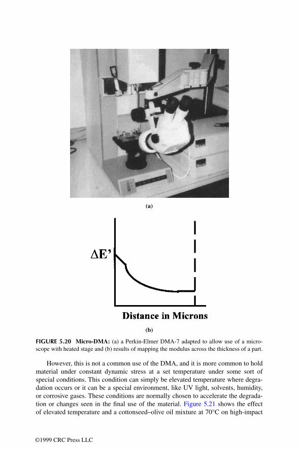
DN7036138Issue 3-2
117
BSS09006: GPRS System Feature Description GPRS radio connection control
Id:0900d80580590b60
For information on network-controlled cell re-selection, see:
• Network-Controlled Cell Re-selection • Inter-System Network-Controlled Cell Re-selection
For information on network-assisted cell change, see:
• Network-Assisted Cell Change
9.9 Traffic administrationThe BSC has many overload mechanisms to protect existing traffic flow and thus ensure good quality for end-users.
The cause of an overload may be, for example, in the planning of the network and capacity being too small in a particular area. In the case of overload, neither circuit switched nor GPRS connections can be set up. The BCSU continuously tries, however, to set up the GPRS connection, and the unit can in the worst case thus easily run itself into a state of malfunction. The BCSU cuts down the load by rejecting particular messages when the processor load or the link load exceeds the defined load limit. Circuit switched calls are marked in the same way as GPRS connections.
The load the BCSU can handle has been tested, but the user can determine GPRS usage and thus prevent the overload situations from happening. Refer to section BSS overload protection and flow control in BSS (BSC) Traffic Handling Capacity, Network Planning and Overload Protection for more information on the BSC's overload control in general.
BCSU overload controlThe BCSU has an overload control to protect itself against the processor overloading and the TRXSIG link overloading.
BCSU protection against excessive number of paging messages on the Gb inter-faceThe BCSU cuts down the load by rejecting particular messages when the processor load or the link load exceeds the defined load limit. The BCSU rejects messages which are sent in the downlink direction to the TRXSIG if needed. Each message sent to TRXSIG has a certain message group value. In case the message buffers of an AS7 plug-in unit begin to fill up, the BCSU rejects messages based on the message group value.
The BCSU cuts down the load caused by GPRS and circuit switched paging messages sent by the SGSN. The load control is based on the number of unhandled messages in the BCSU's message queue. The BCSU checks the count of unhandled messages in the message queue every time a new paging message is received. If the load limit is exceeded, the message is deleted.
BCSU protection against high GPRS RACH loadIn the uplink direction the BCSU cuts down the load caused by GPRS random accesses. The BCSU rejects P-CHANNEL_REQUIRED messages received from the TRXSIG if the processor load exceeds the defined load limit. The load control is based on the number of unhandled messages in the BCSU's message queue. The count of unhandled messages in the message queue is checked every time a new P-CHANNEL_REQUIRED message is received. If the load limit is exceeded, the BCSU deletes the message.
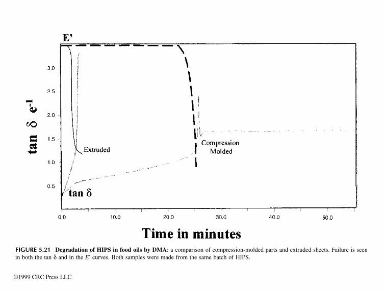
118 DN7036138Issue 3-2
BSS09006: GPRS System Feature Description
Id:0900d80580590b60
GPRS radio connection control
BSSGP flow controlFlow control is part of the BSSGP protocol. It is used to adjust the flow of BSSGP DL-UNITDATA PDUs from SGSN to the PCU. PCU controls the flow by indicating its buffer size and maximum allowed throughput to the SGSN. SGSN is not allowed to transmit more data than indicated by the PCU. Flow control is performed for downlink data in BVC (cell) and MS level. Any uplink flow control is not performed.
PCU holds a buffer for storing downlink data. The amount of the data to be stored in the PCU is optimised for efficient use of the available radio resources. The BVC and MS buffer sizes indicated to the SGSN are controlled by the PRFILE parameters FC_B_MAX_TSL and FC_MS_B_MAX_DEF.
PCU monitors the lifetime values of the buffered DL UNITDATA PDUs. If the lifetime of a PDU expires before the PDU is sent across the radio interface, PCU deletes the PDU locally. Local deletion is signalled to the SGSN by a LLC-DISCARDED PDU.
The 3GPP Rel-5 specifications introduce a third layer for BSSGP flow control: a Packet Flow Context (PFC) flow control. The PFC flow control is an optional functionality.
Flow control mode of operationThe PCU sends an initial FLOW-CONTROL-BVC PDU to the SGSN after a BVC is reset in order to allow SGSN to start the downlink BSSGP data transfer. This message contains BVC specific buffer size and leak rate, as well as default values for MS buffer size and leak rate. The PRFILE parameters FC_B_MAX_TSL and FC_R_TSL define the BVC specific buffer size and leak rate together with the number of actual GPRS timeslots in the cell. The parameters FC_MS_B_MAX_DEF and FC_MS_R_DEF define the MS specific default values. SGSN uses the MS default values for controlling the flow of an individual MS until it receives a FLOW-CONTROL-MS PDU regarding that MS.
Upon reception of a FLOW-CONTROL PDU, SGSN modifies its downlink transmission as instructed and ensures that it never transmits more data than can be accommodated within the BSC buffer for a BVC or an MS.
After the initial BVC FLOW-CONTROL PDU, PCU starts to perform periodic flow control in BVC and MS level. The frequency of FLOW-CONTROL PDUs is limited so that the PCU may send a new PDU once in every C seconds for each flow. The value C in the PCU is fixed to 1 s.
PCU checks the flow control status for each BVC and MS once a second and sends as a periodic FLOW CONTROL PDU to SGSN for the flows which needs to be adjusted. For this purpose the PCU keeps record of the received DL data per BVC and per MS. It knows the buffer utilisation ratio and leak rate of each flow, and compares the actual leak rate value to the value reported earlier to the SGSN. If the leak rate difference for a flow exceeds the PRFILE parameter FC_R_DIF_TRG_LIMIT, the flow control parameters in SGSN needs to be updated. For a BVC flow, the FLOW-CONTROL-BVC PDU and for a MS flow, the FLOW-CONTROL-MS PDU is sent to SGSN.
If the PCU does not receive confirmation to a FLOW-CONTROL PDU, no further action is taken. If the condition which requires flow control remains effective, a new FLOW-CONTROL PDU is sent to the SGSN after one second.
For more information on BVC and MS flow control, refer to BSC-SGSN Interface Spec-ification, BSS GPRS Protocol (BSSGP).
DN7036138Issue 3-2
119
BSS09006: GPRS System Feature Description GPRS radio connection control
Id:0900d80580590b60
Uplink congestion control on NS-VCThe BSC/PCU uses a local congestion control procedure to adapt uplink NS-UNITDATA traffic to the NS-VCs according to their throughput. The PCU sends an NS-UNITDATA, which passes the procedure, to the SGSN as long as the CIR of the NS-VC is not exceeded.
The PCU deletes any NS-UNITDATA that does not pass the procedure. This updates a counter, and the BSC sets the alarm 3027 UPLINK CONGESTION ON THE NETWORK SERVICE VIRTUAL CONNECTION in the BSC. The alarm is cancelled automatically, when NS-UNITDATA again passes the procedure.
9.10 Coding scheme selection in GPRSStealing bits in the channel coding (for more information, see ETSI specification on Channel Coding) are used to indicate the actual coding scheme (CS) which is used for each block sent between the BSC's PCU and the MS.
In downlink packet transfer the PCU selects the CS, and the code word for the selected CS is included in each RLC data block sent to the MS. If the PCU changes the CS during one TBF reservation, it includes the new CS code word in the blocks.
In uplink data transfer, the PCU informs the MS the initial CS to be used in either the IMMEDIATE_ASSIGNMENT or PACKET_UPLINK_ASSIGNMENT message. The PCU can command the MS to change the CS by sending the PACKET_UPLINK_ACK/NACK message, which includes the Channel Coding Command field. In retransmission the same CS has to be used as in the initial block transmission.
In PCU1 the coding schemes CS-1 and CS-2 are supported. In PCU2 the coding schemes CS-3 and CS-4 are introduced. Although the CS-3 and CS-4 coding schemes are licence based, the Link Adaptation algorithm is still provided with PCU2. However, in case the operator has both PCU1 and PCU2 in use in the same track, coding schemes CS-1 and CS-2 can only be used and the Link Adaptation algorithm with coding scheme no hop (COD) and coding scheme hop (CODH) parameters is deployed.
PCU1The BSC level parameters coding scheme no hop (COD) and coding scheme hop (CODH) define whether the fixed CS value (CS-1/CS-2) is used or if the coding scheme is changed dynamically according to the Link Adaptation algorithm. In unac-knowledged RLC mode CS-1 is always used regardless of the parameter values. When the Link Adaptation algorithm is deployed, then the initial value for the CS at the begin-ning of a TBF is CS-2.
Link Adaptation algorithm
The Link Adaptation (LA) algorithm is used to select the optimum channel coding scheme (CS-1 or CS-2) for a particular RLC connection and it is based on detecting the occurred RLC block errors.
Essential for the LA algorithm is the crosspoint, where the two coding schemes give the same bit rate. In terms of block error rate (BLER) the following equation holds at the crosspoint:
8.0 kbps * (1 - BLER_CP_CS1) = 12 kbps * (1 - BLER_CP_CS2), where:
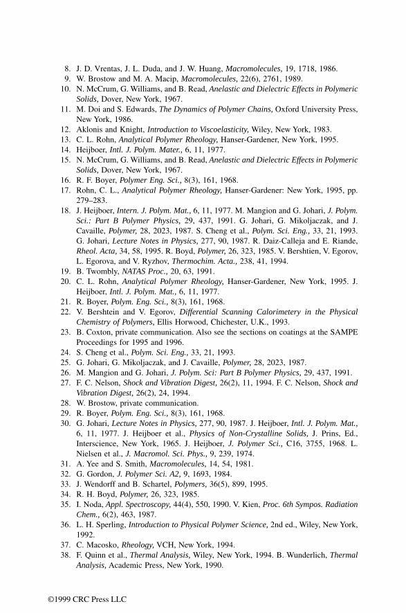
120 DN7036138Issue 3-2
BSS09006: GPRS System Feature Description
Id:0900d80580590b60
GPRS radio connection control
• 8.0 kbps is the theoretical maximum bit rate for CS-1 • 12.0 kbps is the theoretical maximum bit rate for CS-2 • BLER_CP_CS1 is the block error rate at the crosspoint when CS-1 is used • BLER_CP_CS2 is the block error rate at the crosspoint when CS-2 is used
If CS-1 is used and if BLER is less than BLER_CP_CS1, then it would be advantageous to change to CS-2. If CS-2 is used and if BLER is larger than BLER_CP_CS2, then it would be advantageous to change to CS-1. Since CS-1 is more robust than CS-2, BLER_CP_CS2 is larger than BLER_CP_CS1.
The crosspoint can be determined separately for UL and DL directions as well as for fre-quency hopping (FH) and non-FH cases. For this purpose the following BSC-level parameters are used by the LA algorithm:
• UL BLER crosspoint for CS selection hop (ULBH) • DL BLER crosspoint for CS selection hop (DLBH)
• UL BLER crosspoint for CS selection no hop (ULB)
• DL BLER crosspoint for CS selection no hop (DLB)
The given parameters correspond to the BLER_CP_CS1 (see equation above).
During transmission, two counters are updated: N_Number gives the total number of RLC data blocks and K_Number gives the number of corrupted RLC data blocks that have been transmitted after the last link adaptation decision.
At certain intervals (in uplink transfer after approximately 10 transmitted RLC blocks, and in downlink after every PACKET_DL_ACK/NACK message reception) the LA algo-rithm is run by performing two of the following (either 1 and 2 or 3 and 4) statistical tests:
1. Current coding scheme is CS-1; change to CS-2?
Hypothesis: BLER > BLER_CP_CS1.
Reference case: N_Number of blocks have been transmitted with a constant BLER value of BLER_CP_CS1. In this reference case the number of erroneous blocks follow binomial distribution and the P-value gives the probability to get at most K_Number of block errors out of N_Number of transmissions.
P-value =
If the P-value is less than a certain risk level (RL), the hypothesis can be rejected with (1-RL) confidence. If the hypothesis is rejected, it means that the reference case would hardly give the observed measures with the given condition of BLER > BLER_CP_CS1. If this is the case, then it can be concluded that BLER < BLER_CP_CS1.
Action in case the hypothesis is rejected: Change to CS-2. Reset counters N_Number and K_Number.
Action in case the hypothesis is accepted: No actions.
2. Current coding scheme is CS-1; confirm CS-1?
Hypothesis: BLER < BLER_CP_CS1.
Reference case: N_Number of blocks have been transmitted with a constant BLER value of BLER_CP_CS1. In this reference case the number of erroneous blocks follow binomial distribution and the P-value gives the probability to get at least K_Number of block errors out of N_Number of transmissions.

DN7036138Issue 3-2
121
BSS09006: GPRS System Feature Description GPRS radio connection control
Id:0900d80580590b60
P-value =
If the P-value is less than a certain risk level, the hypothesis can be rejected with (1-RL) confidence. This means that the reference case would hardly give the observed measures with the condition of BLER < BLER_CP_CS1. If this is the case, then it can be concluded that BLER > BLER_CP_CS1.
Action in case the hypothesis is rejected: Reset counters N_Number and K_Number (CS-1 is confirmed).
Action in case the hypothesis is accepted: No actions.
3. Current coding scheme is CS-2; change to CS-1?
Hypothesis: BLER < BLER_CP_CS2.
Reference case: N_Number of blocks have been transmitted with a constant BLER value of BLER_CP_CS2. In this reference case the number of erroneous blocks follow binomial distribution and the P-value gives the probability to get at least K_Number of block errors out of N_Number of transmissions.
P-value =
If P-value is less than a certain risk level, the hypothesis can be rejected with (1-RL) con-fidence. This means that the reference case would hardly give the observed measures with the condition of BLER < BLER_CP_CS2. If this is the case, then it can be concluded that BLER > BLER_CP_CS2.
Action in case the hypothesis is rejected: Change to CS-1. Reset counters N_Number and K_Number.
Action in case the hypothesis is accepted: No actions.
4. Current coding scheme is CS-2; confirm CS-2?
Hypothesis: BLER > BLER_CP_CS2.
Reference case: N_Number of blocks have been transmitted with a constant BLER value of BLER_CP_CS2. In this reference case the number of erroneous blocks follow binomial distribution and the P-value gives the probability to get at most K_Number of block errors out of N_Number of transmissions.
P-value =
If P-value is less than a certain risk level, the hypothesis can be rejected with (1-RL) con-fidence. This means that the reference case would hardly give the observed measures with the condition of BLER > BLER_CP_CS2. If this is the case, then it can be concluded that BLER < BLER_CP_CS2.
Action in case the hypothesis is rejected: Reset counters N_Number and K_Number (CS-2 is confirmed).
Action in case the hypothesis is accepted: No actions.

122 DN7036138Issue 3-2
BSS09006: GPRS System Feature Description
Id:0900d80580590b60
GPRS radio connection control
In practice the threshold K_Number values have been computed beforehand to look-up tables indexed with respect to the N_Number and the link adaptation decisions can be performed by simply comparing the observed K_Number with the theshold K_Number values.
The Risk Level parameters (UL adaption probability threshold (ULA) and DL adaption probability threshold (DLA)) describe the probability with which the LA algorithm may make a wrong conclusion to reject a given hypothesis. In other words, they determine the sensitivity of the LA algorithm. The larger the risk level, the more quickly the LA algorithm is able react to changes in BLER by switching the coding scheme but on the other hand the reliability of the switching decision is lowered as the risk level is increased.
The PCU chooses a lower CS than what the Link Adaptation algorithm allows, if there is no room in the dynamic Abis pool for the higher CS allowed by the LA.
PCU2The Link Adaptation algorithm
In PCU2 the coding schemes CS-1 - CS-4 are supported. The BTS level parameters DL coding scheme in acknowledged mode (DCSA), UL coding scheme in acknowledged mode (UCSA), DL coding scheme in unacknowledged mode (DCSU) and UL coding scheme in unacknowledged mode (UCSU) define whether the fixed CS value (CS-1 - CS-4) is used or if the coding scheme is changed dynamically according to the Link Adaptation algorithm. The parameter DL coding scheme in acknowledged mode (DCSA) defines it in RLC acknowledged mode in downlink direction, UL coding scheme in acknowledged mode (UCSA) defines it in RLC acknowledged mode in uplink direction and so on. The BTS level parameter adaptive LA algorithm (ALA) defines whether the Link Adaptation algorithm is adaptive or not.
The new Link Adaptation algorithm can be used both in RLC acknowledged and in unac-knowledged modes both in uplink and downlink direction. When the Link Adaptation algorithm is deployed, the initial values for the CS at the beginning of a TBF can also be defined with the parameters DL coding scheme in acknowledged mode (DCSA), UL coding scheme in acknowledged mode (UCSA), DL coding scheme in unacknowledged mode (DCSU) and UL coding scheme in unacknowledged mode (UCSU).
Note, however, that when a GPRS MS already has a TBF and a new TBF is established for the MS to the opposite direction, then the initial value of the CS of the new TBF is set to be the same that is currently used by the ongoing TBF.
The new Link Adaptation algorithm replaces the current LA algorithm in GPRS and covers the coding schemes:
• CS-1 and CS-2 if the CS-3 and CS-4 support is not enabled in the territory • CS-1, CS-2, CS-3 and CS-4, if the CS3 and CS-4 support is enabled in the territory
The new LA algorithm is based on the following principles:
• The signal quality is measured for each TBF in terms of RXQUAL, which describes the channel quality with the accuracy of eight levels (RXQUAL is expressed with three bits). Note that RXQUAL is measured for each received RLC radio block. On a block basis RXQUAL is thus more accurate estimate than the BLER, which has only two levels: 0 and 1.
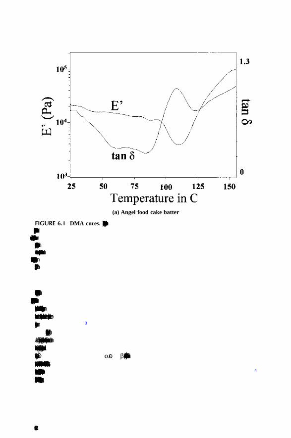
DN7036138Issue 3-2
123
BSS09006: GPRS System Feature Description GPRS radio connection control
Id:0900d80580590b60
• The PCU determines internally the average BLER separately for each coding scheme and reported RXQUAL value. This is done separately in each cell by col-lecting statistics continuously from all the connections in the corresponding cell.
• Based on the statistics (common for all the TBFs in the cell) and the received RXQUAL estimate (specific to the given TBF), the PCU is able to estimate what the BLER would be if CS1, CS2, CS3 or CS4 were deployed for this TBF. Moreover, based on these BLER estimates the PCU can compute which coding scheme would give the best performance, that is the highest throughput in RLC acknowledged mode.
• The new LA algorithm adapts to the radio characteristics of the cell because the BLER is dynamically measured as a function of RXQUAL and coding scheme. Therefore, there is no need for pre-determined threshold values that are traditionally used in link adaptation.
Operation in downlink direction
The PCU uses two 2-dimensional tables (ACKS and NACKS) for the LA operation (another set of ACKS and NACKS tables are needed for UL direction). In these tables, the first index refers to the coding scheme and the second index refers to the RXQUAL value. Initially the ACKS and NACKS tables are initialised with values obtained from the simulations. Therefore, the operation of the LA algorithm is initially based on the simu-lation results.
The PCU has separate ACKS and NACKS tables as well as separate initialisation for hopping and non-hopping BTSs.
During the DL data transfer the mobile station measures the signal quality (RXQUAL) from the RLC radio blocks that are successfully decoded and addressed to the mobile station. The RXQUAL is averaged over the received RLC blocks and the averaged RXQUAL estimate is sent to the network in the Packet DL Ack/Nack messages. There can be eight different values for the RXQUAL. When the PCU receives a valid Packet DL Ack/Nack message for the DL TBF that operates in an RLC acknowledged mode, the received bitmap is analysed and the corresponding RLC blocks are marked as ACKED, if a positive acknowledgement is received, or as NACKED, if a negative acknowledgement is received. In this procedure, the RLC updates the ACKS and NACKS tables as follows:
• Whenever an RLC block is positively acknowledged, ACKS [CS][RXQ] = ACKS [CS][RXQ] + 1, where CS indicates the coding scheme with which this RLC block was transmitted and RXQ refers to the RXQUAL value received in this particular Packet DL Ack/Nack message.
• Whenever an RLC block is negatively acknowledged, NACKS [CS][RXQ] = NACKS [CS][RXQ] + 1, where CS indicates the coding scheme with which this RLC block was originally transmitted and RXQ refers to the RXQUAL value received in this par-ticular Packet DL Ack/Nack message.
If the value of the parameter adaptive LA algorithm (ALA) is N (disabled), the RLC does not update ACKS and NACKS tables but only the initial values of those tables will be used when the LA algorithm selects the optimal CS.
The ACKS and NACKS tables contain ever-increasing figures. In the long run the figures would overflow resulting in erroneous behavior. To solve this, both figures are divided by 2, when the sum (ACKS [CS][RXQ] + NACKS [CS][RXQ]) for CS and RXQ exceeds a certain threshold value.
Coding scheme selection in downlink direction in RLC acknowledged mode

124 DN7036138Issue 3-2
BSS09006: GPRS System Feature Description
Id:0900d80580590b60
GPRS radio connection control
After the bitmap is processed, the LA algorithm selects the optimal coding scheme for a TBF as follows:
1. The throughput of the link is estimated for each coding scheme separately as follows: throughput [CS] = K * ACKS [CS][RXQ] / (ACKS [CS][RXQ] + NACKS [CS][RXQ]) * RATE[CS], where: CS = CS-1, CS-2, CS-3, CS-4, if CS-3 and CS-4 support is enabled in the territory, otherwise CS = CS-1, CS-2. • K is a correction factor that takes into account the throughput reduction due to
the RLC protocol stalling • RXQ is the RXQUAL value that was received in the newly-processed Packet DL
Ack/Nack message • RATE[4] -table contains the theoretical maximum throughput values for the
available channel coding schemes2. The coding scheme is selected based on the highest throughput with the condition
of BLER (CS) < QC_ACK_BLER_LIMIT_T , where BLER(CS) = NACKS [CS] [RXQ] / (ACKS[CS] [RXQ] + NACKS [CS] [RXQ]). If no CS fulfills this condition, the coding scheme CS-1 is selected.
The correction factor K depends on the BLER and on the number of RLC radio blocks scheduled to the TBF within the RLC acknowledgement delay. Its value has been deter-mined by simulations.
Coding scheme selection in downlink direction in RLC unacknowledged mode
In unacknowledged mode RLC does not have to update the ACKS and NACKS tables but it can use the same ACKS and NACKS tables updated by the TBFs in acknowledged mode.
The coding schemes that are in an unacknowledged mode are selected by choosing the highest CS for which BLER (CS) < QC_UNACK_BLER_LIMIT_T, where BLER (CS) = NACKS [CS] [RXQ] / (ACKS[CS] [RXQ] + NACKS [CS] [RXQ]) and RXQ is the RXQUAL estimate that is received in the Packet DL Ack/Nack message. If these conditions are not fulfilled the coding scheme CS-1 is selected.
If the MS does not aswer to polling, the coding number will be decreased step-by-step as follows:
• If one Packet DL Ack/Nack message is missed with CS-4, then the coding scheme is changed to CS-3.
• If two subsequent Packet DL Ack/Nack messages are missed with CS-3, then the coding scheme is changed to CS-2.
• If three subsequent Packet DL Ack/Nack messages are missed with CS-2, then the coding scheme is changed to CS-1
Operation in uplink direction
In UL direction the channel quality estimate can be either RXQUAL or GMSK_BEP depending on the Abis interface. The PCU data frame used in the non-EDGE Abis inter-face reports the channel quality in terms of RXQUAL, which is expressed with three bits. In this case the only possible coding schemes are CS-1 and CS-2.
The PCU uses two 2-dimensional tables (ACKS and NACKS) for LA operation. In these tables, the first index refers to the coding scheme and the second index refers to the RXQUAL or GMSK BEP value. Initially the ACKS and NACKS tables are initialised to the values obtained from the simulations.
The PCU has separate ACKS and NACKS tables as well as separate initialisation for hopping and non-hopping BTSs.
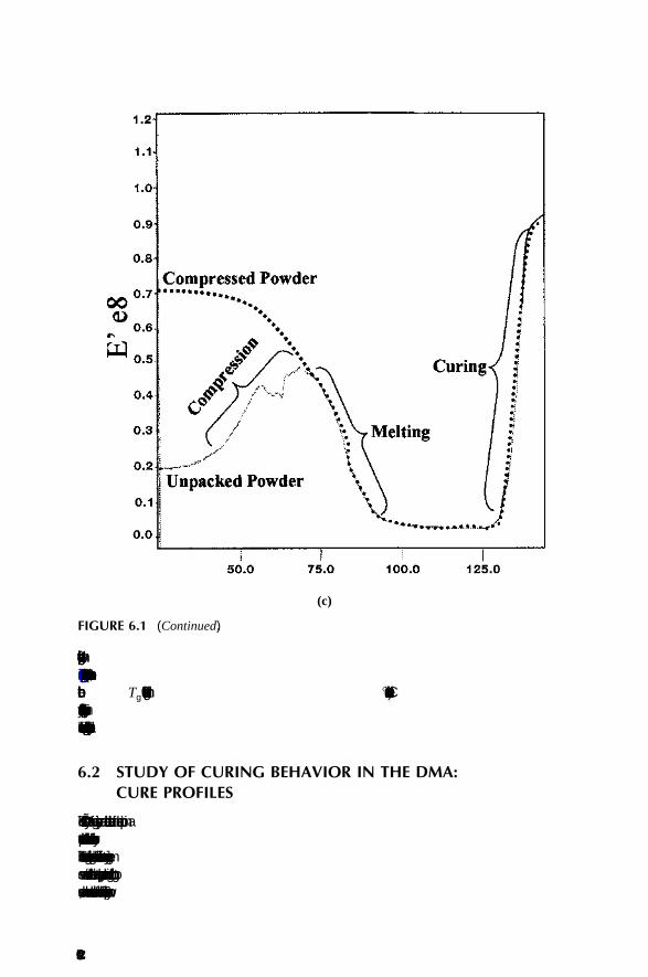
DN7036138Issue 3-2
125
BSS09006: GPRS System Feature Description GPRS radio connection control
Id:0900d80580590b60
In case of RXQUAL, the RLC averages the RXQUAL estimates sent by the BTS for the correctly received RLC radio blocks. This is done for each uplink TBF.
In case of GMSK_BEP, the RLC averages the GMSK_BEP estimates sent by the BTS for both correctly and erroneously received RLC radio blocks. This is done for each UL TBF. The GMSK_BEP estimate is made also from the bad frames because the GMSK_BEP estimate for successfully received CS-4 blocks alone approaches zero in all radio conditions (there is no error correction in CS-4).
During the UL data transfer the PCU updates the ACKS and NACKS tables as follows:
Whenever a new RLC block is successfully received, ACKS [CS][RXQ] = ACKS [CS][RXQ] + 1, where CS indicates the coding scheme with which this RLC block was transmitted and RXQ refers to the current RXQUAL or GMSK BEP estimate for this UL TBF. Whenever a RLC block is received unsuccessfully, NACKS [CS][RXQ] = NACKS [CS][RXQ] + 1, where CS indicates the coding scheme with which this RLC block was transmitted and RXQ refers to the current RXQUAL or GMSK BEP estimate for this UL TBF.
As in the DL case the figures in the ACKS and NACKS tables are limited so that when the sum (ACKS [CS][RXQ] + NACKS [CS][RXQ]) for certain CS and RXQ exceeds a certain threshold value, both figures are divided by 2.
Coding scheme selection in uplink direction in RLC acknowledged mode
1. The throughput of the link is estimated for each coding scheme separately as follows: throughput [CS] = K * ACKS [CS][RXQ] / (ACKS [CS][RXQ] + NACKS [CS][RXQ]) * RATE [CS], where: CS = CS-1, CS-2, CS-3, CS-4, if CS-3 and CS-4 support is enabled in the territory, otherwise CS = CS-1, CS-2. K is a correction factor that takes into account the throughput reduction due to the RLC protocol stall-ing, RXQ is the current RXQUAL or GMSK BEP estimate for this UL TBF and RATE [4] -table contains the theoretical maximum throughput values for the available channel coding schemes.
2. The coding scheme is selected based on the highest throughput with the condition of BLER (CS) <QC_ACK_BLER_LIMIT_T, where BLER (CS) = NACKS [CS] [RXQ] / (ACKS [CS] [RXQ] + NACKS [CS] [RXQ]). If no CS fulfills this condition, the coding scheme CS-1 is selected. The same correction factor table K can be used as in the DL case.
Coding scheme selection in uplink direction in RLC unacknowledged mode
In unacknowledged mode the RLC message does not have to update the ACKS and NACKS tables but it can use the same ACKS and NACKS tables that are updated by the TBFs in acknowledged mode. The coding schemes are selected in unacknowledged mode as follows:
The coding schemes that are in an unacknowledged mode are selected by choosing the highest CS for which BLER (CS) < QC_UNACK_BLER_LIMIT_T, where BLER (CS) = NACKS [CS] [RXQ] / (ACKS [CS] [RXQ] + NACKS [CS] [RXQ]) and RXQ is the current RXQUAL or GMSK BEP estimate for this UL TBF. If these conditions are not fulfilled for any CS the coding scheme CS-1 is selected.
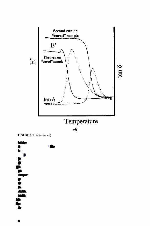
126 DN7036138Issue 3-2
BSS09006: GPRS System Feature Description
Id:0900d80580590b60
GPRS radio connection control
9.11 Power controlGPRS power control consists of the uplink power control. Due to the data bursts in traffic, the power control is not as effective as for circuit switched traffic.
Power control is used for optimising the signal strength from MS to BTS. The operator can use the cell-specific parameters binary representation ALPHA (ALPHA) and binary representation TAU (GAMMA) to optimise the signal strength. The gamma parameter ( Γ CH in the figure) sets the minimum MS output power level, and the alpha parameter ( α in the figure) sets the slope for field strength effect to uplink power level.
Figure 24 Uplink power control
The power of each block needs to be sufficient for two MSS:
• The MS receiving the data • The MS receiving the Uplink State Flag (USF determines the uplink transmission
turn in case several mobiles have been assigned to the same uplink PDTCH).
9.12 MS Radio Access Capability updateWhen the PCU needs to know the MS's RAC information, but the information is not avail-able in the PCU, the PCU initiates an MS RAC enquiry from the SGSN. The enquiry is carried out by the Gb interface Radio Access Capability Update procedure defined in 3GPP 48.018. There are two PRFILE parameters controlling the procedure. Parameter TGB_RAC_UPDATE defines T5 /48.018/, and parameter RAC_UPDATE_RETRIES defines RA-CAPABILITY-UPDATE-RETRIES /48.018/.
0
510
1520
2530
35
-45
-50
-55
-60
-65
-70
-75
-80
-85
-90
-95
-100
-105
-110
Signal Strength (dBm)
gamma_ch = 30 alfa = 0.8
gamma_ch = 20, alfa = 0.3
• Uplink power control
M S Outpu tPower (dBm)
DN7036138Issue 3-2
127
BSS09006: GPRS System Feature Description Implementing GPRS
Id:0900d80580590b66
10 Implementing GPRS
10.1 Implementing GPRS overviewPurposeImplementing GPRS means activating GPRS in BSC.
You can implement GPRS in the network by using BSC MMI or NetAct. In NetAct, GPRS parameters can be modified with Plan Editor and the Routing Area can be created with CM Editor.
For detailed instructions, see Activating and Testing BSS9006: GPRS.
Before you startTo enable GPRS in a BSC, you must have valid licences for the following:
• PCU or PCU2 • GPRS or EGPRS
Steps
1 Enable GPRS in the BSC.
2 Modify GPRS.Typical instances for modifying GPRS are caused by changes in capacity, and related tasks could thus be, for example, modifying the Gb interface or routing areas (RAs).
3 Disable GPRS in the BSC.Disabling GPRS is a reverse operation to that of taking GPRS into use, starting from dis-abling GPRS on a cell level to deleting the Routing Areas (RAs) and removing the Gb interface connection and required units.
It is possible to disable GPRS on a cell or TRX level, and not to disable GPRS alto-gether. This way, you only need to activate GPRS again in the cell or the TRX to bring GPRS into use.
Further information
• Activating and Testing BSS9006: GPRS • Enabling GPRS in the GSM radio network in NetAct Product Documentation
Related Documents