Physics Letters A 160 ( 1991 ) 45-54 North-Holland PHYSICS LETTERS A Noise attenuators for gravity experiments in space A.M. Nobili, G. Catastini Gruppo di Meccanica Spaziale, Dipartimento di Matematica, Universitd di Pisa, Via Buonarroti 2, 1-56127 Pisa, Italy A. di Virgilio lstituto Nazionale di Fisica Nucleare, Sezione di Pisa, 1-56010 San Piero a Grado, Pisa, Italy V. IafoUa Istituto di Fisica dello Spazio Interplanetario, CNR, Via Galileo Galilei, 1-00044 Frascati, Italy and F. Fuligni Istituto di Astrofisica Spaziale, CNR, Via Enrico Fermi, 1-00044 Frascati, Italy Received 24 May 1991; accepted for publication 10 June 199 I Communicated by J.P. Vigier Space is highly advantageous for small force experiments. However, they are seriously limited by spacecraft vibrational noise. We present a passive attenuator which allows one to realize a noise-free laboratory inside any flying structure. The attenuator works between a fraction of I Hz and 1000 Hz. In the two-stage version the residual disturbance can be 10- ~o cm s -2 with very short integration times. A third stage makes it even lower. 1. Introduction Ground experiments on gravity are severely lim- ited by the extreme weakness of the gravitational in- teraction as compared to other forces normally pres- ent in the earth environment. Measuring the universal constant of Newton's law is one of such difficult experiments, as it requires one to measure accelerations as small as 10 -'° cm s -2 [ 1 ]. Testing the equivalence principle between inertial and grav- itational mass requires detecting the effects of very small accelerations too. In the experiment of Roll et al. [ 2 ] of the acceleration resulting from possible vi- olation of the equivalence principle was at about the same level. Small force gravitational experiments do take ad- vantage of the free fall property of the spacecraft en- vironment, where the largest net acceleration which is unavoidable on earth - the local acceleration of gravity g - is absent. However, disturbances such as atmospheric drag, solar radiation pressure, space- craft mass attraction and a number of others, are by no means negligible when one aims at detecting small gravitational effects. Drag-free satellites, capable of compensating for non-gravitational forces and thus moving under the influence of gravity alone, have been the subject of many studies. However, they are limited by high cost and technological complexity. Here we describe a double-stage, passive, noise at- tenuator made of mechanical oscillators. It is capa- ble of substantially reducing noise between 0.8 and 1000 Hz in an experimental box placed inside a non- drag-free spacecraft. A small force experiment based upon the detection of a gravity signal in this range of frequencies can be carried out inside the box with great advantage. Vibrational noise above 10 Hz is so drastically damped (below t0-'° cm s -2, with very short integration times) that other perturbations will 0375-9601/91/$ 03.50 © 1991 Elsevier Science Publishers B.V. All rights reserved. 45

Welcome message from author
This document is posted to help you gain knowledge. Please leave a comment to let me know what you think about it! Share it to your friends and learn new things together.
Transcript
Physics Letters A 160 ( 1991 ) 45-54 North-Holland
PHYSICS LETTERS A
Noise attenuators for gravity experiments in space
A.M. Nobili, G. Catastini Gruppo di Meccanica Spaziale, Dipartimento di Matematica, Universitd di Pisa, Via Buonarroti 2, 1-56127 Pisa, Italy
A. di Virgilio lstituto Nazionale di Fisica Nucleare, Sezione di Pisa, 1-56010 San Piero a Grado, Pisa, Italy
V. IafoUa Istituto di Fisica dello Spazio Interplanetario, CNR, Via Galileo Galilei, 1-00044 Frascati, Italy
and
F. Fuligni Istituto di Astrofisica Spaziale, CNR, Via Enrico Fermi, 1-00044 Frascati, Italy
Received 24 May 1991; accepted for publication 10 June 199 I Communicated by J.P. Vigier
Space is highly advantageous for small force experiments. However, they are seriously limited by spacecraft vibrational noise. We present a passive attenuator which allows one to realize a noise-free laboratory inside any flying structure. The attenuator works between a fraction of I Hz and 1000 Hz. In the two-stage version the residual disturbance can be 10- ~o cm s -2 with very short integration times. A third stage makes it even lower.
1. Introduction
Ground exper iments on gravity are severely lim- i ted by the extreme weakness of the gravi ta t ional in- teract ion as compared to other forces normal ly pres- ent in the earth environment . Measuring the universal constant o f Newton 's law is one o f such difficult experiments , as it requires one to measure accelerat ions as small as 10 - ' ° cm s -2 [ 1 ]. Testing the equivalence principle between inertial and grav- i ta t ional mass requires detect ing the effects o f very small accelerat ions too. In the exper iment o f Roll et al. [ 2 ] o f the accelerat ion resulting from possible vi- olat ion o f the equivalence pr inciple was at about the same level.
Small force gravi ta t ional exper iments do take ad- vantage of the free fall proper ty o f the spacecraft en- v i ronment , where the largest net accelerat ion which is unavoidable on earth - the local accelerat ion o f
gravity g - is absent. However, dis turbances such as a tmospher ic drag, solar radia t ion pressure, space- craft mass a t t ract ion and a number of others, are by no means negligible when one aims at detecting small gravi ta t ional effects. Drag-free satellites, capable of compensat ing for non-gravi tat ional forces and thus moving under the influence of gravity alone, have been the subject of many studies. However, they are l imited by high cost and technological complexity. Here we describe a double-stage, passive, noise at- tenuator made of mechanical oscillators. It is capa- ble o f substantial ly reducing noise between 0.8 and 1000 Hz in an exper imental box placed inside a non- drag-free spacecraft. A small force exper iment based upon the detect ion o f a gravity signal in this range o f frequencies can be carr ied out inside the box with great advantage. Vibrat ional noise above 10 Hz is so drast ical ly d a m p e d (below t 0 - ' ° cm s -2, with very short integrat ion t imes) that o ther per turbat ions will
0375-9601/91/$ 03.50 © 1991 Elsevier Science Publishers B.V. All rights reserved. 45
Volume 160, number 1 PHYSICS LETTERS A 4 November 1991
be the limiting ones. Ways of reducing them are dis- cussed. Sources of gravitational perturbations are in- vestigated too. It is shown that they are ineffective provided the frequency of the experiment signal is properly chosen. The results of a three-stage atten- uator are also reported. It allows one to reach very low levels of noise also at low frequencies, as well as to reduce high frequency noise even further.
Once spacecraft noise is eliminated - although not for all frequencies - it becomes possible to carry out small force experiments on any spacecraft with no need for dedicated missions. Past experience shows that dedicated space missions take very long time - up to a considerable fraction of a scientist's active life. Furthermore, they lack both repeatibility and flexibility. All this should change in the Space Sta- tion era. The Columbus Precursor Flights, leading to the Space Station itself, allow repeatibility (hence also flexibility), a reasonable number of flight opo portunities and acceptable timescales. The price to pay is obviously the need to cope with a highly per- turbed spacecraft environment.
2. Spacecraft noise versus seismic noise
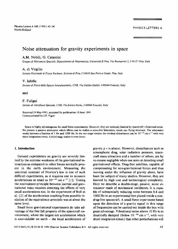
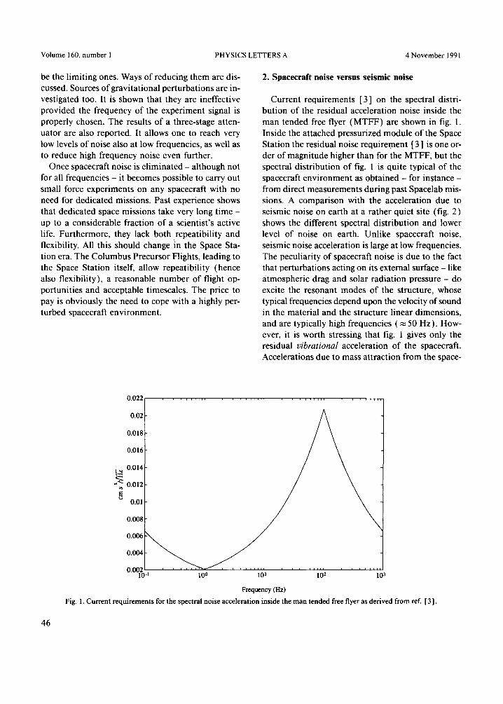
Current requirements [ 3] on the spectral distri- bution of the residual acceleration noise inside the man tended free flyer (MTFF) are shown in fig. 1. Inside the attached pressurized module of the Space Station the residual noise requirement [ 3 ] is one or- der of magnitude higher than for the MTFF, but the spectral distribution of fig. 1 is quite typical of the spacecraft environment as obtained - for instance - from direct measurements during past Spacelab mis- sions. A comparison with the acceleration due to seismic noise on earth at a rather quiet site (fig. 2) shows the different spectral distribution and lower level of noise on earth. Unlike spacecraft noise, seismic noise acceleration is large at low frequencies. The peculiarity of spacecraft noise is due to the fact that perturbations acting on its external surface - like atmospheric drag and solar radiation pressure - do excite the resonant modes of the structure, whose typical frequencies depend upon the velocity of sound in the material and the structure linear dimensions, and are typically high frequencies ( ~ 50 Hz). How- ever, it is worth stressing that fig. 1 gives only the residual vibrational acceleration of the spacecraft. Accelerations due to mass attraction from the space-
0 . 0 2 2 , , , , , , , , , , , , , , . . . . , . . . . . . . . , , , , , , , ,
0.02
0.018
0.016
0.014
"[~ 0.012
0.01
0.008
0.0062 ~ ' 0.004
, , , , , i i . . . . , , , i l l
0"001-0 -t 100 l0 t 102 103
Frequency (Hz) Fig. 1. Current requirements for the spectral noise acceleration inside the man tended free flyer as derived from ref. [ 3 ].
46
Volume 160, number 1 PHYSICS LETTERS A 4 November 1991
1.2
1
0.8
0.6
0.4
0.2
i
00 10
x10-3 1.4
20 30 40 50 60 70 80 90 100
Frequency (Hz)
Fig. 2. Seismic noise spectral acceleration at Cascina, as measured by the Virgo group of the 1NFN laboratory in Pisa.
craft itself and - more important - those coming from any moving masses inside it, should be carefully con- sidered (see section 3).
3. Spacecraft noise and its reduction
Attenuators of seismic noise have been built in the framework of experiments for the detection of grav- ity waves, as resonant antennas and suspended mir- rors need to be freed from seismic noise. For in- stance, the noise attenuator [4] devised for the resonant cryogenic antenna of the IFSI CNR Insti- tute in Frascati, uses mechanical oscillators along the longitudinal direction of the antenna reducing noise by a factor of about 10-12 at the resonant frequency of 2 kHz. At the INFN laboratory in Pisa, scientists involved in the Virgo project for the detection of low frequency gravity waves by laser interferometry, have built a passive attenuator [5,6] which involves a seven-stage system of air springs and is capable of reducing seismic noise by a factor of about 10 - 9 in all six degrees of freedom (three for translation and three for rotation) above a threshold frequency of 10 n z .
Passive noise attenuators rely on the fact that when
the suspension point of a pendulum is forced at a fre- quency co much larger than the resonant frequency tOo of the pendulum, the oscillation amplitude of the suspended mass is reduced with respect to that of the suspension point by a factor (too/to) 2. A system of n pendula in cascade - all with resonant frequency much smaller than the perturbing one - would re- duce the oscillation amplitude of the suspended mass at the bottom by a factor (too/to) 2n.
It was pointed out by A. Milani that the same prin- ciple of passive noise attenuation can be exploited inside space structures. Indeed, space offers crucial advantages. First of all, the absence of weight elim- inates the need for "strong" springs, and this fact has important consequences. For an Eureca-type of orbit as assumed in table 1 the atmospheric drag pertur- bation is aaras,~10 -4 cm s -2 (entry 4) and sus- pending a 100 kg box is like suspending an equiva- lent weight of m~xadraJg~O.03 g on earth! Therefore, very low spring constant oscillators can be used, which makes it possible to damp noise above a low threshold frequency by means of an apparatus of limited dimensions. Most important, such a "light" laboratory can be suspended from one point only, so that the spacecraft does not transmit any torque to it and the number of degrees of freedom to be
47
Volume 160, number l PHYSICS LETTERS A 4 November 1991
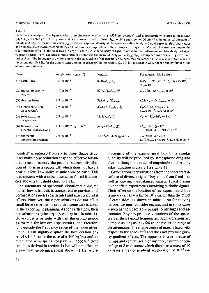
Table 1 Perturbation analysis. The figures refer to an Eureca-type of orbit (~ 525 km altitude) and a spacecraft with area-to-mass ratio (A/M)sc ~ 0.5 cmz g- ~. The experimental box is assumed to be of mass Mbox = l 0 s g and side 1= 100 cm. G is the universal constant of gravity and Ms the mass of the earth. Parr, is the atmospheric density at the spacecraft altitude, d~¢ and v~¢ the spacecraft orbital radius and velocity, Co its form coefficient: they all enter in the computation of the atmospheric drag effect, qoo, which is used to compute the solar radiation effect, is the solar flux (in erg s-t cm-2), c is the velocity of light. K and a are the Boltzmann and blackbody radiation constants respectively. The area-to-mass ratio of a spherical test mass (A/M)tm= (3/4ptm)/rt~ is computed for density 18 g cm- t and radius 3 cm. The frequency too, which enters in the calculation of the thermal noise perturbation (entry 6), is the resonant frequency of the attenuator (0.8 Hz for the double-stage attenuator discussed in this work). Q= l04 is a reasonable value for the quality factor of the aluminum cantilever.
Cause Acceleration ( cm s- 2 ) Formula Parameters ( CGS units )
( 1 ) earth tides 3.6 X 10 -4 3GM,~dbox/d~ G M . = 3.986× 10²°, d~¢= 6.93 x l0 s, dbo~= 100
( 2 ) spacecraft gravity I. 17 × 10 -7 2G(AM)~cd~,,/D 3 D = 200, (AM)~ = 7 X 10⁴ gradient
(3) thruster firing 6.7 × 10 -H G(AAl)thr/D2thr_box (/~d~/)lhr = 10, Othr_box= 100
(4) atmospheric drag 2.9 × 10 - 4 ICo(A/m)scPatmV2 CD~2, (A/M)~¢.~0.5, on spacecraft ,Oatm m 1 0 - 1 5 Vsc ~'~ 7 .6 X 10 s
(5) solar radiation 2.3 × 10 -5 (A/M)~qbo/c ~ o = 1.38× 10 6, ¢ = 3× 10 ~° on spacecraft
(6)thermalnoise 1.3 ×10⁻¹¹tO1/ZHz -I/2 (4tOoKT/Mt,o~Q) 1/2 Mbox=10S, Q=104, ( spectral distribution ) T= 300 K, K= 1.381 × I 0 -~6
(7) spacecraft 2 .9 × 10 -9 (4aT4/C)(A/M)tmAT/T T=300 K, AT= I K, temperature gradient (A/M)t,.,= lAX l0 -2, e= 5.67× l0 -5
" c o o l e d " is r educed f r o m six to three. Space struc-
tures m a k e noise r educ t ion easy and e f fec t ive for an-
o ther reason, n a m e l y the pecu l ia r spectral d is t r ibu-
t ion o f noise in a spacecraft , which does not have a
peak at a few Hz - unl ike seismic noise on earth. This
is cons is tent wi th a noise a t t enua to r for all f requen-
cies above a th resho ld close to l Hz.
An a t t enua to r o f spacecraf t v ib ra t iona l noise, no
m a t t e r how it is built , is t r anspa ren t to g rav i ta t iona l
pe r tu rba t ions such as ear th t ides and spacecraf t mass
effects. Howeve r , these pe r tu rba t ions do not affect
small force expe r imen t s p r o v i d e d s o m e care is t aken
in the e x p e r i m e n t p lanning. As for ear th t ides, the i r
pe r tu rba t ion is qu i te large (see en t ry in l in table 1 ).
However , it is pe r iod ic wi th ha l f the orbi ta l pe r iod
( ~ 90 min for low orb i t spacecra f t ) , and there fore
falls ou t s ide the f requency range o f the noise a t ten-
uator. It will sl ightly displace the box loca t ion (by 1.4X l0 - s cm in the case o f a 100 kg box and an
a t t enua to r wi th spr ing cons tan t k = 2 . 5 × 10 6 dyne
cm - ~, as de r ived in sect ion 4 ) bu t will no t affect an expe r imen t i nvo lv ing a signal above ~ 1 Hz. A dis-
p l a c e m e n t o f the expe r imen ta l box by a s imi la r
quan t i ty will be p roduced by a tmosphe r i c drag and
also - a l though one o rde r o f m a g n i t u d e smal le r - by
solar r ad ia t ion pressure (see table 1 ).
G r a v i t a t i o n a l pe r tu rba t ions f rom the spacecraf t it-
self are o f d iverse origin. They c o m e f r o m f ixed - as
well as m o v i n g - unba l anced masses. F ixed masses
do no t affect expe r imen t s i nvo lv ing per iod ic signals.
T h e i r effect on the loca t ion o f the expe r imen ta l box
is anyway small - a fac tor 103 smal le r than the effect
o f ear th tides, as shown in table I. As for m o v i n g
masses, we mus t cons ide r engines and in s o m e cases
- such as the Spacelab - pumps , centr i fuges and as-
t ronauts . Engines p roduce v ib ra t ions o f the space- craft at the i r typical f requencies . Such v ib ra t ions are
d a m p e d as long as they fall in the r educ t ion range o f
the at tenuator . The engine centre o f mass is f ixed with
respect to the spacecraf t and does no t p roduce grav-
ity grad ien t effects. T h e oppos i te is t rue in case o f
p u m p s and centr ifuges. F o r instance, a p u m p or cen-
t r i fuge at 2 m d is tance which displaces a mass o f 10 kg gives a gravi ty grad ien t acce lera t ion o f 10-8 cm
48
Volume 160, number 1 PHYSICS LETTERS A 4 November 1991
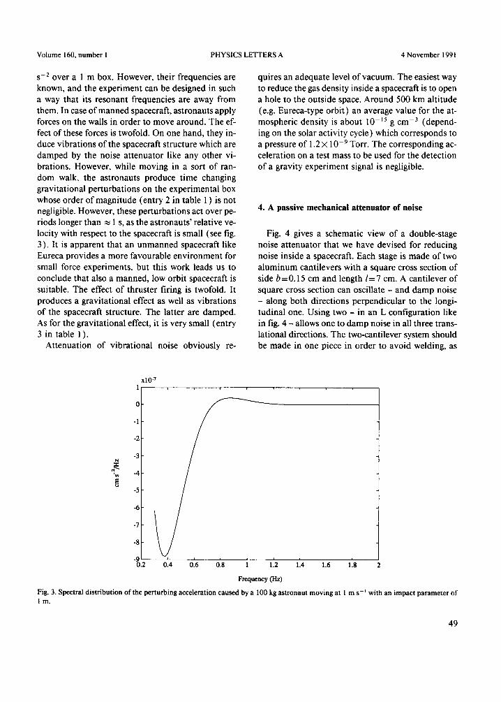
s -2 over a 1 m box. However, their frequencies are known, and the experiment can be designed in such a way that its resonant frequencies are away from them. In case o f manned spacecraft, astronauts apply forces on the walls in order to move around. The ef- fect o f these forces is twofold. On one hand, they in- duce vibrations o f the spacecraft structure which are damped by the noise attenuator like any other vi- brations. However, while moving in a sort of ran- dom walk, the astronauts produce time changing gravitational perturbations on the experimental box whose order of magnitude (entry 2 in table 1 ) is not negligible. However, these perturbations act over pe- riods longer than ~ 1 s, as the astronauts ' relative ve- locity with respect to the spacecraft is small (see fig. 3). It is apparent that an unmanned spacecraft like Eureca provides a more favourable environment for small force experiments, but this work leads us to conclude that also a manned, low orbit spacecraft is suitable. The effect of thruster firing is twofold. It produces a gravitational effect as well as vibrations o f the spacecraft structure. The latter are damped. As for the gravitational effect, it is very small (entry 3 in table 1 ).
Attenuation of vibrational noise obviously re-
quires an adequate level of vacuum. The easiest way to reduce the gas density inside a spacecraft is to open a hole to the outside space. Around 500 km altitude (e.g. Eureca-type orbiO an average value for the at- mospheric density is about 10-~5 g cm-3 (depend- ing on the solar activity cycle) which corresponds to a pressure o f 1.2 × 10 - 9 Torr. The corresponding ac- celeration on a test mass to be used for the detection of a gravity experiment signal is negligible.
4. A pass ive m e c h a n i c a l at tenuator o f no i se
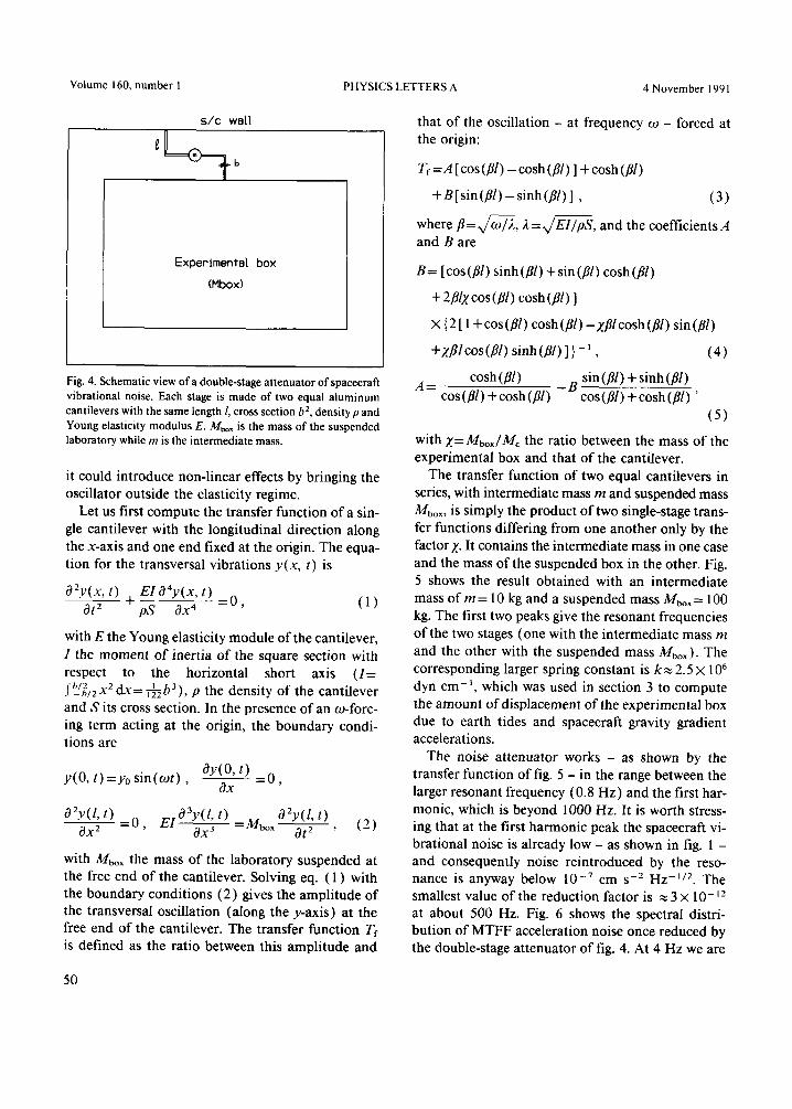
Fig. 4 gives a schematic view of a double-stage noise attenuator that we have devised for reducing noise inside a spacecraft. Each stage is made of two aluminum cantilevers with a square cross section of side b = 0.15 cm and length l= 7 cm. A cantilever of square cross section can oscillate - and damp noise - along both directions perpendicular to the longi- tudinal one. Using two - in an L configuration like in fig. 4 - allows one to damp noise in all three trans- lational directions. The two-cantilever system should be made in one piece in order to avoid welding, as
xlO-7 1
0
-I
-2
-3
-4
-5
-6
-7
-8
i i i i i -v.2 0,4 0.6 0.8 1 1 2
Frequency (Hz)
116 118
Fig. 3. Spectral distribution of the perturbing acceleration caused by a 100 kg astronaut moving at 1 m s - t with an impact parameter of l m .
49
Volume 160, number 1 PHYSICS LETTERS A 4 November 1991
s/c wall
ExperlmentBl box
(Hbox)
Fig. 4. Schematic view of a double-stage attenuator of spacecraft vibrational noise. Each stage is made of two equal aluminum cantilevers with the same length 1, cross section b 2, density p and Young elasticity modulus E. Mbox is the mass of the suspended laboratory while m is the intermediate mass.
it could introduce non-linear effects by bringing the oscillator outside the elasticity regime.
Let us first compute the transfer function of a sin- gle cantilever with the longitudinal direction along the x-axis and one end fixed at the origin. The equa- tion for the transversal vibrations y(x , t) is
O2y(x, t) EIO4y(x, t) Ot ~ + - - =0, (1) pS Ox 4
with E the Young elasticity module of the cantilever, I the moment of inertia of the square section with respect to the horizontal short axis ( I = fb_/~/2X2 dx= ~ b 3 ) , p the density of the cantilever and S its cross section. In the presence of an m-forc- ing term acting at the origin, the boundary condi- tions are
y(0, t) =Yo sin(ogt), Oy(O, t) = 0 , Ox
O2y(l, t) t) . O2y(l, t) 19X2 = 0 , E / 1 9 3 ~ ( / ; =2V/box ~ , ( 2 )
with Mbox the mass of the laboratory suspended at the free end of the cantilever. Solving eq. ( 1 ) with the boundary conditions (2) gives the amplitude of the transversal oscillation (along the y-axis) at the free end of the cantilever. The transfer function Tr is defined as the ratio between this amplitude and
that of the oscillation - at frequency ¢o - forced at the origin:
Tf=A [cos(ill) - cosh (ill) ] + cosh (ill)
+B[sin(ill) - sinh(ill) ] , (3)
where it= x / ~ , 2 = E x / ~ p S , and the coefficients A and B are
B= [cos(ill) sinh(ill) +sin(ill) cosh (ill)
+ 2illx cos (ill) cosh (ill) ]
× {2 [ 1 +cos(ill) cosh (ill) -)cillcosh(ill) sin(ill)
+zfllcos(ill) sinh (ill) ]} - l , (4)
A= cosh (ill) - B sin (ill) + sinh (ill) cos(ill)+cosh(ill) cos(ill)+cosh(ill) '
(5)
with X=Mbox/Mc the ratio between the mass of the experimental box and that of the cantilever.
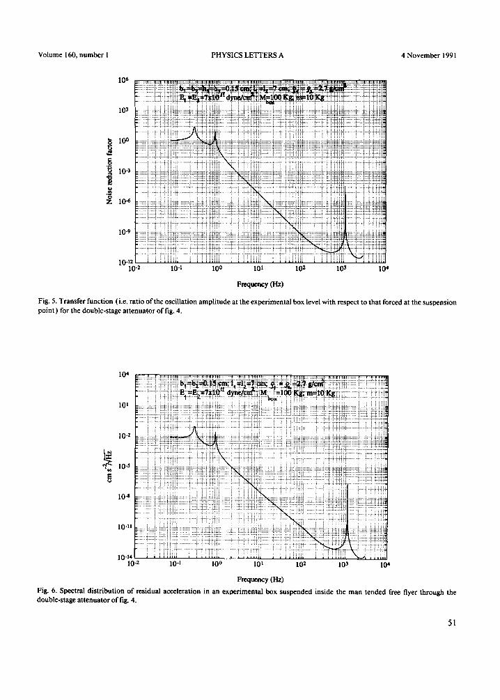
The transfer function of two equal cantilevers in series, with intermediate mass m and suspended mass Mbox, is simply the product of two single-stage trans- fer functions differing from one another only by the factor Z. It contains the intermediate mass in one case and the mass of the suspended box in the other. Fig. 5 shows the result obtained with an intermediate mass of m = 10 kg and a suspended mass Mbox = 100 kg. The first two peaks give the resonant frequencies of the two stages (one with the intermediate mass m and the other with the suspended mass Mbox). The corresponding larger spring constant is k~ 2.5 X l 0 6
dyn cm -t , which was used in section 3 to compute the amount of displacement of the experimental box due to earth tides and spacecraft gravity gradient accelerations.
The noise attenuator works - as shown by the transfer function of fig. 5 - in the range between the larger resonant frequency (0.8 Hz) and the first har- monic, which is beyond 1000 Hz. It is worth stress- ing that at the first harmonic peak the spacecraft vi- brational noise is already low - as shown in fig. 1 - and consequently noise reintroduced by the reso- nance is anyway below 10 -7 c m s -2 H z -1/2. The smallest value of the reduction factor is ~ 3 × 10- J 2
at about 500 Hz. Fig. 6 shows the spectral distri- bution of MTFF acceleration noise once reduced by the double-stage attenuator of fig. 4. At 4 Hz we are
50
Volume 160, number 1 PHYSICS LETTERS A 4 November 1991
I0~
10 3
10 o
"~= 10-~
:~ 10-6
10-9
10-12 10 .2 10 "t I0 o I0~ 102 103 104
Frequency (Hz)
Fig. 5. Transfer function (i.e. ratio of the oscillation amplitude at the experimental box level with respect to that forced at the suspension point ) for the double-stage attenuator of fig. 4.
10~
l0 t
10-2
,~ I0 "s
10 4
lO-n
10-14 10-2 10-1 10 o 101 10 2 10 3 10 4
Frequency (Hz)
Fig. 6. Spectral distribution of residual acceleration in an experimental box suspended inside the man tended free flyer through the double-stage attenuator of fig. 4.
51
Volume 160, number 1 PHYSICS LETTERS A 4 November 1991
already at the level of 10 -~ cm s -2 Hz -~/2, after which the residual acceleration drops sharply. At 30 Hz the residual acceleration is 10 -~° cm s -2 H z - ' / 2 !
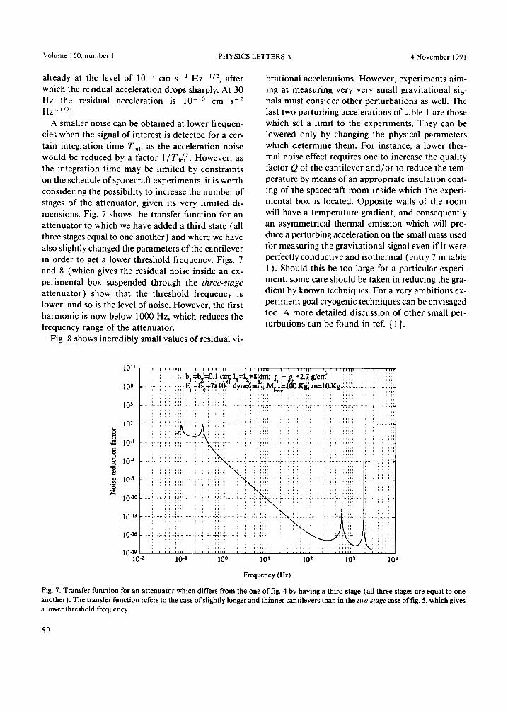
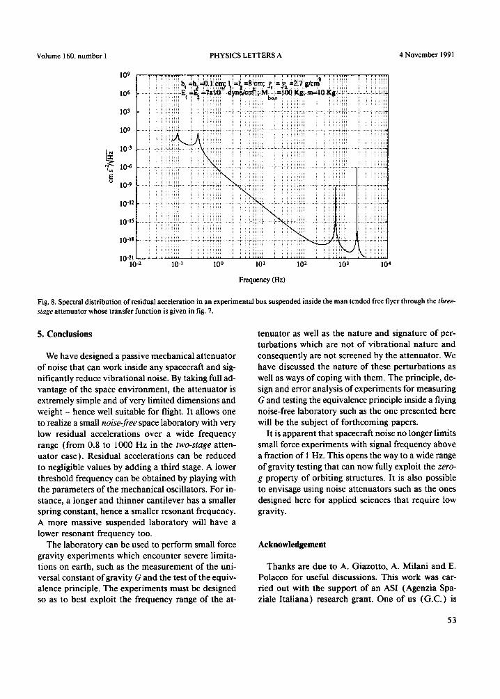
A smaller noise can be obtained at lower frequen- cies when the signal of interest is detected for a cer- tain integration time T~,~, as the acceleration noise would be reduced by a factor 1/T~/~ 2. However, as the integration time may be limited by constraints on the schedule of spacecraft experiments, it is worth considering the possibility to increase the number of stages of the attenuator, given its very limited di- mensions. Fig. 7 shows the transfer function for an attenuator to which we have added a third state (all three stages equal to one another) and where we have also slightly changed the parameters of the cantilever in order to get a lower threshold frequency. Figs. 7 and 8 (which gives the residual noise inside an ex- perimental box suspended through the three-stage attenuator) show that the threshold frequency is lower, and so is the level of noise. However, the first harmonic is now below 1000 Hz, which reduces the frequency range of the attenuator.
Fig. 8 shows incredibly small values of residual vi-
brational accelerations. However, experiments aim- ing at measuring very very small gravitational sig- nals must consider other perturbations as well. The last two perturbing accelerations of table 1 are those which set a limit to the experiments. They can be lowered only by changing the physical parameters which determine them. For instance, a lower ther- mal noise effect requires one to increase the quality factor Q of the cantilever and/or to reduce the tem- perature by means of an appropriate insulation coat- ing of the spacecraft room inside which the experi- mental box is located. Opposite walls of the room will have a temperature gradient, and consequently an asymmetrical thermal emission which will pro- duce a perturbing acceleration on the small mass used for measuring the gravitational signal even if it were perfectly conductive and isothermal (entry 7 in table 1 ). Should this be too large for a particular experi- ment, some care should be taken in reducing the gra- dient by known techniques. For a very ambitious ex- periment goal cryogenic techniques can be envisaged too. A more detailed discussion of other small per- turbations can be found in ref. [ 1 ].
i ii bl=h~=O.iiC'm l~=l~=S[em-~ = ~ =2~7 S/C~ l O , ...... ....... ] i i ! ! ! '
1o 5
1o 2
i0.i
10 4
10 o
Z 10 -l°
i0-13
10-16
1 0 . 1 9 , , , , , , , , , , , , , , , i ~ i i i i l ; ; i l i , , ~ , i , i ~ i i i i ~ i i . , i , i i i i i
1 0 "2 1 0 "1 1 0 0 1 0 1 1 0 2 1 0 3 1 0 4
Frequency (Hz)
Fig. 7. Transfer function for an attenuator which differs from the one of fig. 4 by having a third stage (all three stages are equal to one another). The transfer function refers to the case of slightly longer and thinner cantilevers than in the two-stage case of fig. 5, which gives a lower threshold frequency.
52
V o l u m e 160, n u m b e r 1 P H Y S I C S L E T T E R S A 4 N o v e m b e r 1991
10 9 I !i i : : : : b .=b~=O.F:Cm; l . : := l~=g: :Cin 'S :=y~=2iTg/cm : : i : : : : : . :: :: :: :: :: i :: :: [
: : ::::::: : . : :-:.'/ : :: "::- : ' :x : : .:::::: : : ::::::
....... ~....~..~..i.~.~.~.~ E.. = ~ =Tx.10. . . .~yne/C~.~M.. . ~=I.00 Kg~.m=10 Kg.~.~.i~.~ ....... i....~.4.~., i • I06 ! ~ !~i i i ~ zi:~ : : ~ i :: bo~ ! i i :: ! :: :: :: :: i i i ili::i~l
.................................. i-!ii ...... i!i ...... i ......... i ....... i i .............. i-i-!iii .............. ii-! 1001 .......... i ....... i i l i TiT ........... i i i ......... i .......... i i .............. T ilTi ! ........ T il 10.3
10-9
10-12
i0-15
10-n
10-21 10-2 10-1 10 0 101 10 2 10 3 10 4
Frequency (Hz)
Fig. 8. Spectra l d i s t r i bu t ion o f res idua l accelera t ion in an expe r imen ta l box s u s p e n d e d ins ide the m a n t ended free flyer t h r o u g h the three- stage a t t e n u a t o r whose t r ans fe r f unc t i on is g iven in fig. 7.
5. Conclusions
We have designed a passive mechanical attenuator of noise that can work inside any spacecraft and sig- nificantly reduce vibrational noise. By taking full ad- vantage of the space environment, the attenuator is extremely simple and of very limited dimensions and weight - hence well suitable for flight. It allows one to realize a small noise-free space laboratory with very low residual accelerations over a wide frequency range (from 0.8 to 1000 Hz in the two-stage atten- uator case). Residual accelerations can be reduced to negligible values by adding a third stage. A lower threshold frequency can be obtained by playing with the parameters of the mechanical oscillators. For in- stance, a longer and thinner cantilever has a smaller spring constant, hence a smaller resonant frequency. A more massive suspended laboratory will have a lower resonant frequency too.
The laboratory can be used to perform small force gravity experiments which encounter severe limita- tions on earth, such as the measurement of the uni- versal constant of gravity G and the test of the equiv- alence principle. The experiments must be designed so as to best exploit the frequency range of the at-
tenuator as well as the nature and signature of per- turbations which are not of vibrational nature and consequently are not screened by the attenuator. We have discussed the nature of these perturbations as well as ways of coping with them. The principle, de- sign and error analysis of experiments for measuring G and testing the equivalence principle inside a flying noise-free laboratory such as the one presented here will be the subject of forthcoming papers.
It is apparent that spacecraft noise no longer limits small force experiments with signal frequency above a fraction of I Hz. This opens the way to a wide range of gravity testing that can now fully exploit the zero- g property of orbiting structures. It is also possible to envisage using noise attenuators such as the ones designed here for applied sciences that require low gravity.
Acknowledgement
Thanks are due to A. Giazotto, A. Milani and E. Polacco for useful discussions. This work was car- ried out with the support of an ASI (Agenzia Spa- ziale Italiana) research grant. One of us (G.C.) is
53
Volume 160, number 1 PHYSICS LETTERS A 4 November 1991
gra te fu l to Te l e spaz io for a w a r d i n g h i m a fe l lowship .
References
[ 1 ] A.M. Nobili, A. Milani, E. Polacco, l.W. Roxburgh, F. Barlier, K. Aksnes, C.W.F. Everitt, P. Farinella, L. Anselmo and Y. Boudon, ESA J. 14 (1990) 389.
[2] P.G. Roll, R. Krotkov and R.H. Dicke, Ann. Phys. (NY) 26 ( 1964 ) 442.
[3] Columbus System Requirements, ESA-ESTEC Doc. No. COL-RQ-ESA-001 (1988).
[4] F. Fuligni and F. Ricci, Nuovo Cimento 4C ( 1981 ) 93. [5 ] R. del Fabbro, A. di Virgilio, A. Giazotto, H. Kautzky, V.
Montelatici and D. Passuello, Phys. Lett. A 124 (1987) 253. [6] R. del Fabbro, A. di Virgilio, A. Giazotto, H. Kautzky, V.
Montelatici and D. Passuello, Phys. Lett. A 132 ( 1988 ) 237.
54
Related Documents