HepcoMotion ® No. 8 DTS Components This data sheet interacts with PRT2 Catalogue 50-51 HepcoMotion ® N E W - E x t e n d e d R a n g e w i t h S t a i n l e s s S t e e l O p t i o n s PrecisionRing and TrackSystem DTS driven track system HepcoMotion ® This data sheet interacts with DTS Catalogue HepcoMotion ® supply a comprehensive range of components and assemblies to enable the 25-351 and 44-612 size track systems to be incorporated into customers own designs complete with drive facility. Many of the components shown in this datasheet can also be used for other sizes of track system. The components are well proven having been used for many years in the HepcoMotion DTS, a complete and ready to use driven track system highly recommended for customers able to use this fully assembled standard product. This datasheet contains details and dimensions for the individual assemblies available. For more information or advice to suit a particular application, please contact Hep co’ s technical depar tment. Idler Pulley Assembly Belt Flight Assembly Drive Belt Carriage Locking Shaft Track Support Beam Extrusion Carriage Locking System Assembly Locking Lever Assembly Drive Shaft Assembly Oval Bottom Plate Assembly Oval Top Plate Assembly Carriage Assembly Drive Pulley Assembly Locking Cam Assembly Trip Latch Assembly

Welcome message from author
This document is posted to help you gain knowledge. Please leave a comment to let me know what you think about it! Share it to your friends and learn new things together.
Transcript
8/2/2019 No.8 DTS Components 02 UK.pdf
http://slidepdf.com/reader/full/no8-dts-components-02-ukpdf 1/19
HepcoMotion®
No. 8 DTS Components
This data sheet
interacts with
PRT2 Catalogue
50-51
HepcoMotion®
N E W
- E x t e
n d e d R a
n g e
w i t h
S t a i n l e s
s S t e e l O
p t i o n s
PrecisionRing and
TrackSystem
DTSdriven track system
HepcoMotion® This data sheetinteracts with
DTS Catalogue
HepcoMotion® supply a comprehensive range of components and assemblies to enable the 25-351 and 44-612 size track systemsto be incorporated into customers own designs complete with drive facility. Many of the components shown in this datasheet can alsobe used for other sizes of track system. The components are well proven having been used for many years in the HepcoMotion DTS, acomplete and ready to use driven track system highly recommended for customers able to use this fully assembled standard product.
This datasheet contains details and dimensions for the individual assemblies available. For more information or advice to suit aparticular application, please contact Hepco’s technical department.
Idler Pulley Assembly
Belt FlightAssembly
Drive Belt
Carriage LockingShaft
Track SupportBeam Extrusion
Carriage LockingSystem Assembly
Locking Lever Assembly
Drive Shaft AssemblyOval BottomPlate Assembly
Oval TopPlate Assembly
CarriageAssembly
Drive PulleyAssembly
Locking CamAssembly
Trip Latch Assembly
8/2/2019 No.8 DTS Components 02 UK.pdf
http://slidepdf.com/reader/full/no8-dts-components-02-ukpdf 2/19
No. 8 DTS Components
2
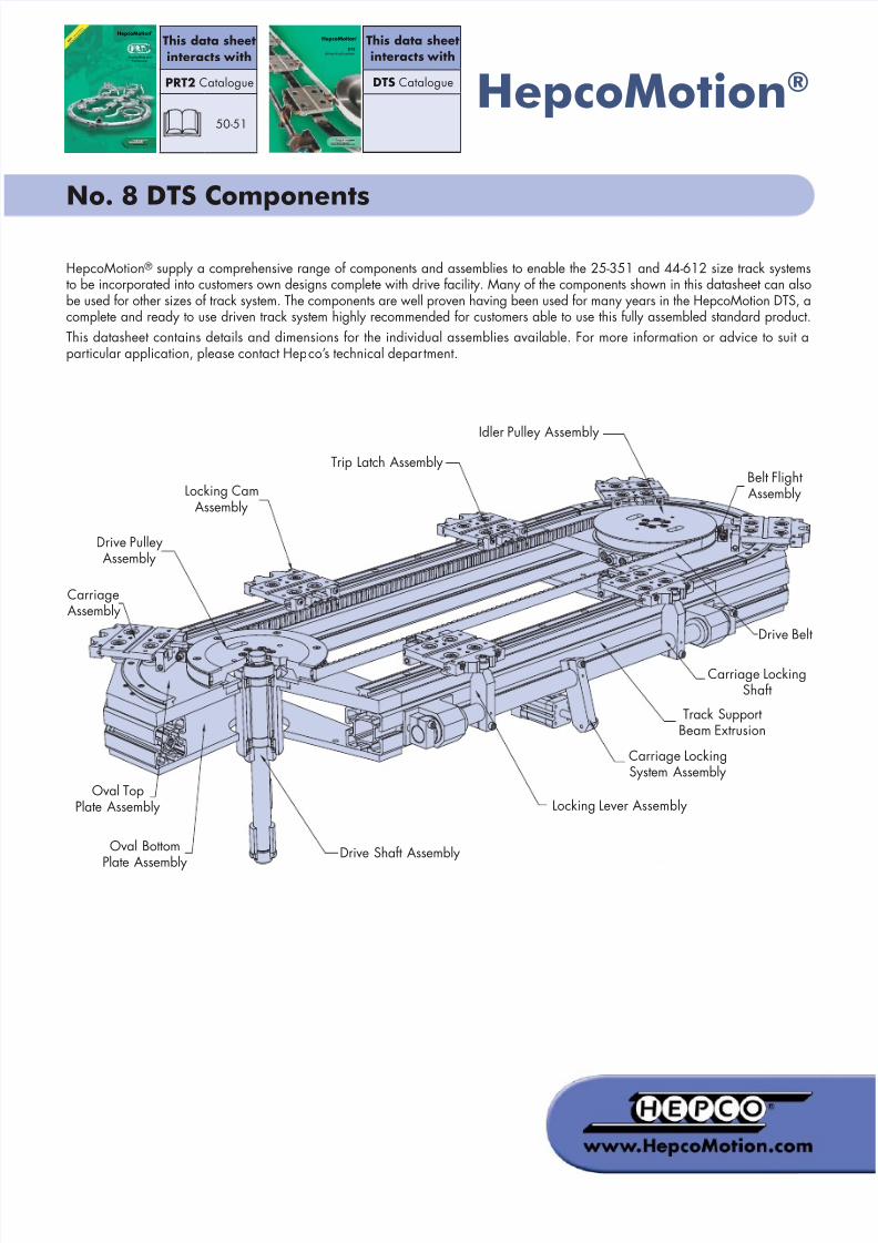
Carriage Assembly
G
C1
B1
O
P
C
IH
A
D
U
E
F
B
S
T
4 x V
2 x M5 Tapped holes
Ø5 dowel holeFor attachmentof locking cam
2 x M5 Tapped HolesFor attachment oflocking cam
For attachment of fixed/trip latch
Customer Mounting Holes
Part Number A B B1 C C1 D E F G H I O P S T U V kg ~
DTS25CPSA 105 80 50 85 40 70 19 26.5 70 21.42 24.25 24.55 23 2 8 10 M6x1 0.42
DTS44CPSA 150 115 75 125 70 102 25.5 35.2 70 37.63 41.17 37.93 35.75 3 10 14 M8x1.25 1
8/2/2019 No.8 DTS Components 02 UK.pdf
http://slidepdf.com/reader/full/no8-dts-components-02-ukpdf 3/19
No. 8 DTS Components
3
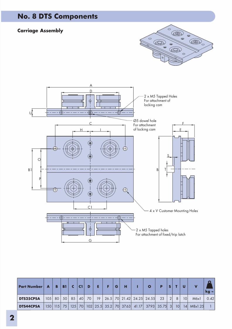
Trip Latch Assembly
Fixed Latch Assembly
Trip load setting screws(adjust both sides)
G
C
D
H
I
F
A
B
E
2 x M5x20 Button head screws
2x M5x20 Button head screws
B
A
D
E
C
F
HG
Part Number A B C D E F G Hkg~
DTS25TLSA 32.75 13.75 5 85 70 39 28.25 18 0.19
DTS44TLSA 33.75 14.75 5 85 70 39 28.25 18 0.19
Part Number A B C D E F G H I kg~
DTS25FLSA 31.75 13.75 5 85 70 38 20 5.5 12 0.18
DTS44FLSA 32.75 14.75 5 85 70 38 20 5.5 12 0.18
8/2/2019 No.8 DTS Components 02 UK.pdf
http://slidepdf.com/reader/full/no8-dts-components-02-ukpdf 4/19
No 8 DTS Components
4
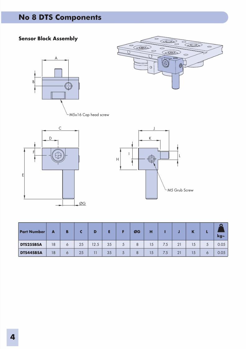
Sensor Block Assembly
ØG
E
M5x16 Cap head screw
C J
K
LI
H
M5 Grub Screw
A
B
D
F
Part Number A B C D E F ØG H I J K Lkg~
DTS25SBSA 18 6 25 12.5 35 5 8 15 7.5 21 15 5 0.05
DTS44SBSA 18 6 25 11 35 5 8 15 7.5 21 15 6 0.05
8/2/2019 No.8 DTS Components 02 UK.pdf
http://slidepdf.com/reader/full/no8-dts-components-02-ukpdf 5/19
No 8 DTS Components
5
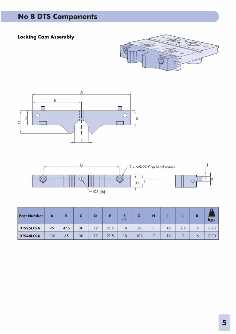
Locking Cam Assembly
K
J2 x M5x20 Cap head screws
H I
Ø5 (J6)
F
G
DC
A
B
E
Part Number A B C D E F(H8)
G H I J Kkg~
DTS25LCSA 95 47.5 30 19 21.5 18 70 11 16 2.5 5 0.23
DTS44LCSA 130 65 30 19 21.5 18 102 11 16 2 6 0.30
8/2/2019 No.8 DTS Components 02 UK.pdf
http://slidepdf.com/reader/full/no8-dts-components-02-ukpdf 6/19
No 8 DTS Components
6
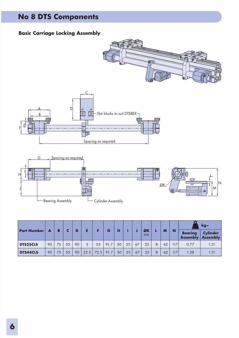
Basic Carriage Locking Assembly
Cylinder AssemblyBearing Assembly
J
HI
G Spacing as required
L
N
MØK
EF
A
B
C
D
Spacing as required
Slot blocks to suit DTSBEX
Part Number A B C D E F G H I J ØK(H8)
L M N
kg~
Bearing
Assembly
Cylinder
Assembly
DTS25CLS 90 75 55 90 5 55 91.7 50 25 67 25 8 62 117 0.77 1.21
DTS44CLS 90 75 55 90 22.5 72.5 91.7 50 25 67 25 8 62 117 1.38 1.21
8/2/2019 No.8 DTS Components 02 UK.pdf
http://slidepdf.com/reader/full/no8-dts-components-02-ukpdf 7/19
No 8 DTS Components
7
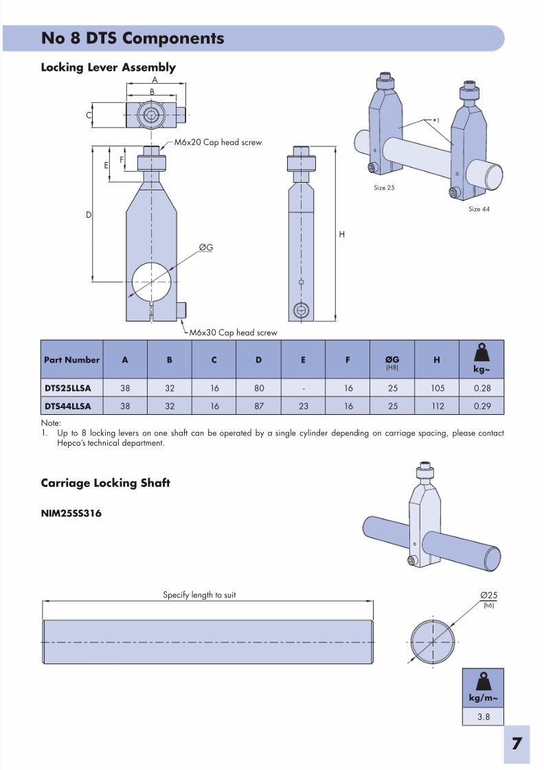
Carriage Locking Shaft
NIM25SS316
Locking Lever Assembly
Size 25
Size 44
Note:1. Up to 8 locking levers on one shaft can be operated by a single cylinder depending on carriage spacing, please contact
Hepco’s technical department.
*1
Ø25Specify length to suit(h6)
H
M6x30 Cap head screw
G
M6x20 Cap head screw
FE
D
B
A
C
Ø
Part Number A B C D E F ØG(H8)
Hkg~
DTS25LLSA 38 32 16 80 - 16 25 105 0.28
DTS44LLSA 38 32 16 87 23 16 25 112 0.29
kg/m~
3.8
8/2/2019 No.8 DTS Components 02 UK.pdf
http://slidepdf.com/reader/full/no8-dts-components-02-ukpdf 8/19
No. 8 DTS Components
8
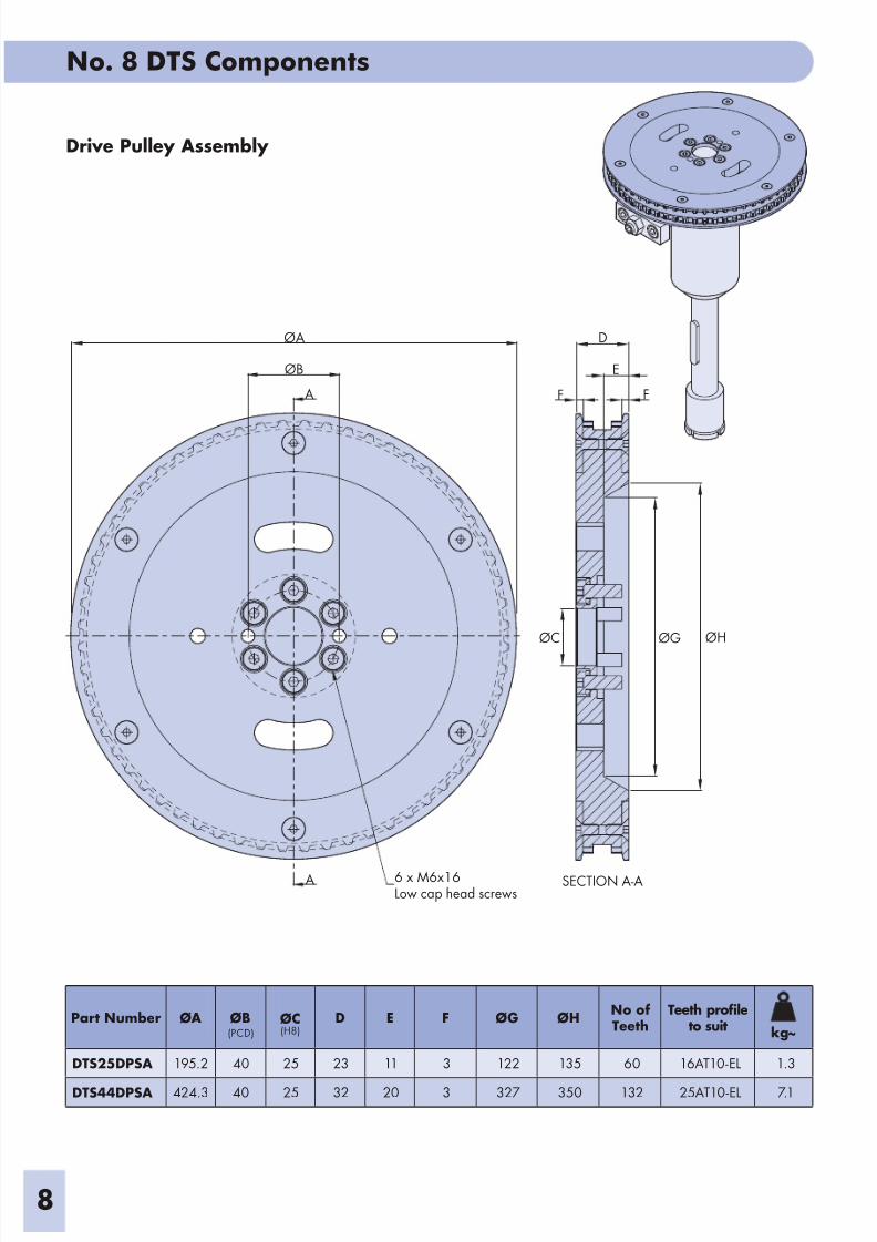
Drive Pulley Assembly
ØG ØHØC
D
E
F F
SECTION A-A6 x M6x16Low cap head screws
A
A
ØB
ØA
Part Number ØA ØB
(PCD)ØC(H8)
D E F ØG ØHNo ofTeeth
Teeth profileto suit kg~
DTS25DPSA 195.2 40 25 23 11 3 122 135 60 16AT10-EL 1.3
DTS44DPSA 424.3 40 25 32 20 3 327 350 132 25AT10-EL 7.1
8/2/2019 No.8 DTS Components 02 UK.pdf
http://slidepdf.com/reader/full/no8-dts-components-02-ukpdf 9/19
No. 8 DTS Components
9
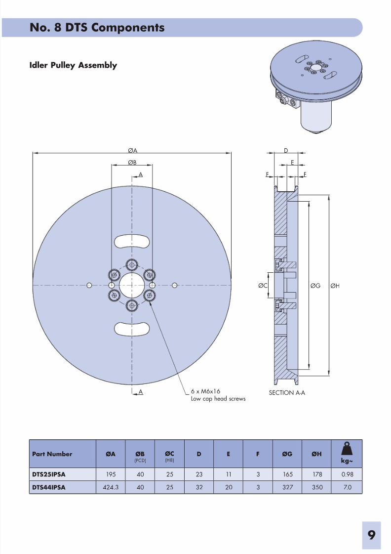
Idler Pulley Assembly
ØB
ØA
6 x M6x16Low cap head screws
A
A
D
E
F F
ØG ØHØC
SECTION A-A
Part Number ØA ØB(PCD)
ØC(H8)
D E F ØG ØHkg~
DTS25IPSA 195 40 25 23 11 3 165 178 0.98
DTS44IPSA 424.3 40 25 32 20 3 327 350 7.0
8/2/2019 No.8 DTS Components 02 UK.pdf
http://slidepdf.com/reader/full/no8-dts-components-02-ukpdf 10/19
No. 8 DTS Components
10
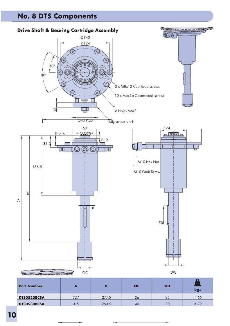
Drive Shaft & Bearing Cartridge Assembly
Ø65
174
M10 Hex Nut
M10 Grub Screw
60
26.5
31.5
156.5
A
B
8
ØC
10 x M6x16 Countersunk screws
2 x M8x12 Cap head screws
Ø140
Ø124
60°
30°
12
ØD
50
Ø25
Ø40 PCD
6 Holes M6x1
(f7)
8.15
Adjustment block
Part Number A B ØC ØDkg~
DTSDS25BCSA 327 277.5 36 25 4.55
DTSDS30BCSA 315 260.5 40 30 4.79
8/2/2019 No.8 DTS Components 02 UK.pdf
http://slidepdf.com/reader/full/no8-dts-components-02-ukpdf 11/19
No. 8 DTS Components
11
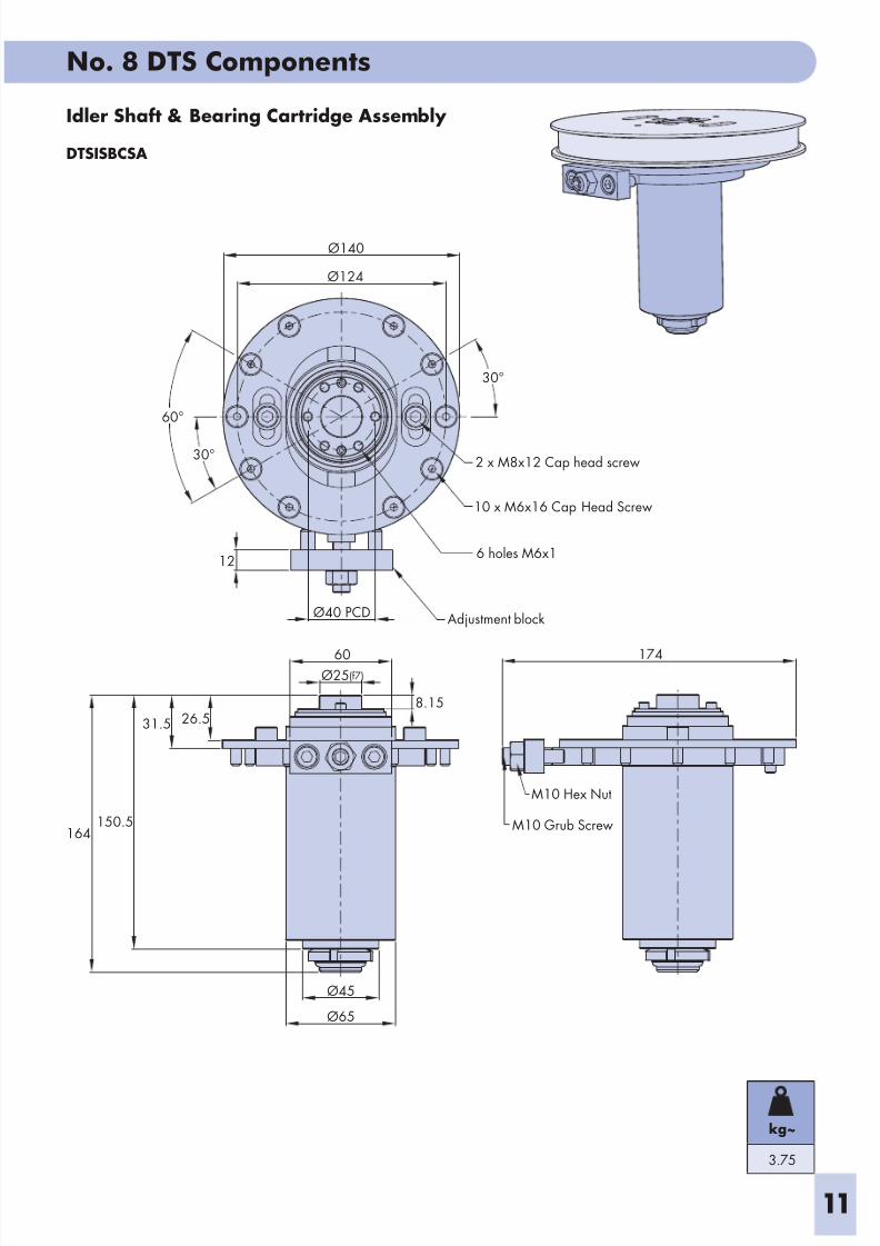
Idler Shaft & Bearing Cartridge Assembly
DTSISBCSA
174
M10 Hex Nut
M10 Grub Screw
2 x M8x12 Cap head screw
26.531.5
150.5164
Ø45
Ø65
60
10 x M6x16 Cap Head Screw
12
Ø140
Ø124
30°
60°
30°
8.15
Ø25
Ø40 PCD
6 holes M6x1
(f7)
Adjustment block
kg~
3.75
8/2/2019 No.8 DTS Components 02 UK.pdf
http://slidepdf.com/reader/full/no8-dts-components-02-ukpdf 12/19
No 8 DTS Components
12
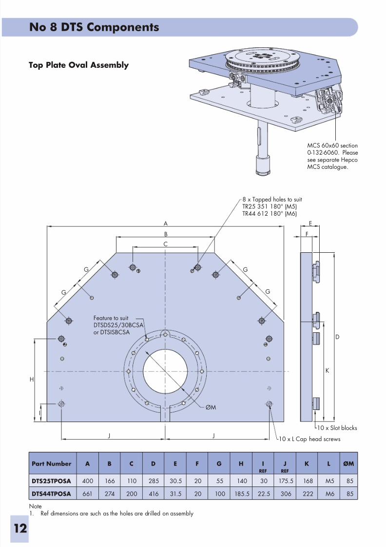
Top Plate Oval Assembly
MCS 60x60 section0-132-6060. Pleasesee separate HepcoMCS catalogue.
J J10 x L Cap head screws
I
H
G
G
Feature to suitDTSDS25/30BCSAor DTSISBCSA
A
C
B
8 x Tapped holes to suitTR25 351 180° (M5)TR44 612 180° (M6)
G
G
ØM
10 x Slot blocks
K
D
F
E
Part Number A B C D E F G H IREF
JREF
K L ØM
DTS25TPOSA 400 166 110 285 30.5 20 55 140 30 175.5 168 M5 85
DTS44TPOSA 661 274 200 416 31.5 20 100 185.5 22.5 306 222 M6 85
Note1. Ref dimensions are such as the holes are drilled on assembly
8/2/2019 No.8 DTS Components 02 UK.pdf
http://slidepdf.com/reader/full/no8-dts-components-02-ukpdf 13/19
No 8 DTS Components
13
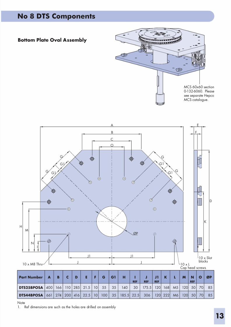
Bottom Plate Oval Assembly
MCS 60x60 section0-132-6060. Pleasesee separate HepcoMCS catalogue.
10 x LCap head screws
10 x Slotblocks
D
K
F
EA
B
C
O
J1
J
J1
J10 x M8 Thru
IN
MH
G G1
G
G1
ØP
GG1
G
G1
Part Number A B C D E F G G1 H IREF
JREF
J1REF
K L M NREF
O ØP
DTS25BPOSA 400 166 110 285 21.5 10 55 35 140 30 175.5 120 168 M5 120 50 70 85
DTS44BPOSA 661 274 200 416 22.5 10 100 35 185.5 22.5 306 120 222 M6 120 50 70 85
Note1. Ref dimensions are such as the holes are drilled on assembly
8/2/2019 No.8 DTS Components 02 UK.pdf
http://slidepdf.com/reader/full/no8-dts-components-02-ukpdf 14/19
No. 8 DTS Components
14
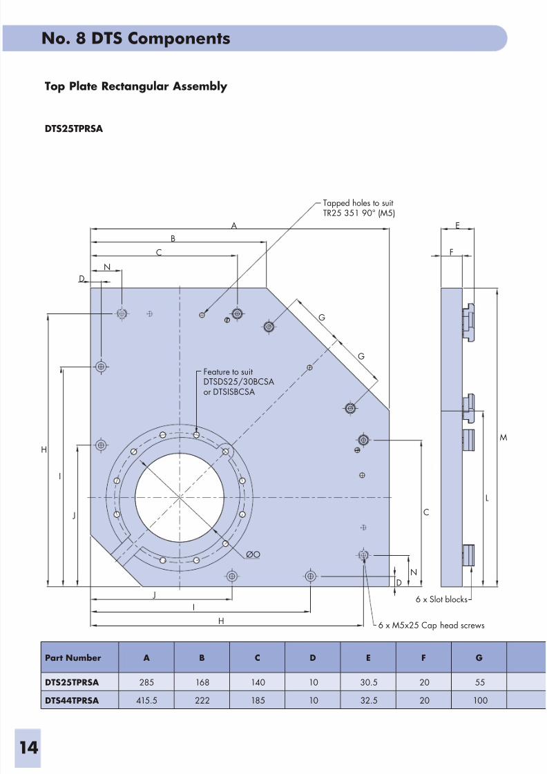
Top Plate Rectangular Assembly
DTS25TPRSA
J
6 x M5x25 Cap head screws
I
H
J
I
H
A
B
C
D N
Tapped holes to suitTR25 351 90° (M5)
F
E
G
G
Feature to suitDTSDS25/30BCSAor DTSISBCSA
ØO
DN
C
6 x Slot blocks
L
M
Part Number A B C D E F G
DTS25TPRSA 285 168 140 10 30.5 20 55
DTS44TPRSA 415.5 222 185 10 32.5 20 100
8/2/2019 No.8 DTS Components 02 UK.pdf
http://slidepdf.com/reader/full/no8-dts-components-02-ukpdf 15/19
No 8 DTS Components
15
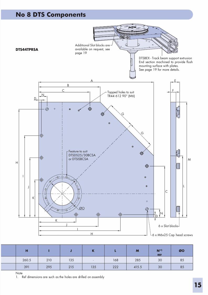
DTS44TPRSADTSBEX - Track beam support extrusionEnd section machined to provide flushmounting surface with plates.See page 19 for more details.
Additional Slot blocks areavailable on request, seepage 19
K
I
H
J
6 x M6x25 Cap head screws
DN
ØO
J
K
H
I
Feature to suit
DTSDS25/30BCSAor DTSISBCSA
DN
C
B
Tapped holes to suitTR44 612 90° (M6)
A E
F
G
G
C
6 x Slot blocks
L
M
H I J K L M N*1
REF
ØO
260.5 210 135 - 168 285 30 85
391 295 215 135 222 415.5 30 85
Note1. Ref dimensions are such as the holes are drilled on assembly
8/2/2019 No.8 DTS Components 02 UK.pdf
http://slidepdf.com/reader/full/no8-dts-components-02-ukpdf 16/19
No 8 DTS Components
16
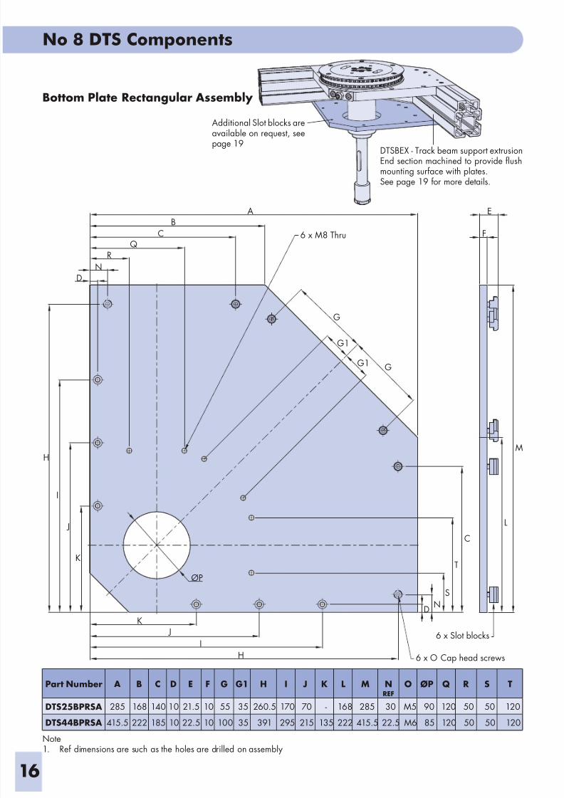
Bottom Plate Rectangular Assembly
DTSBEX - Track beam support extrusionEnd section machined to provide flushmounting surface with plates.See page 19 for more details.
Additional Slot blocks areavailable on request, seepage 19
J
I
K
H 6 x O Cap head screws
6 x Slot blocks
DN
S
T
C
L
M
F
E
GG1
G1
G
6 x M8 Thru
D
N
RQ
CB
A
K
J
I
H
ØP
Part Number A B C D E F G G1 H I J K L M NREF
O ØP Q R S T
DTS25BPRSA 285 168 140 10 21.5 10 55 35 260.5 170 70 - 168 285 30 M5 90 120 50 50 120
DTS44BPRSA 415.5 222 185 10 22.5 10 100 35 391 295 215 135 222 415.5 22.5 M6 85 120 50 50 120
Note1. Ref dimensions are such as the holes are drilled on assembly
8/2/2019 No.8 DTS Components 02 UK.pdf
http://slidepdf.com/reader/full/no8-dts-components-02-ukpdf 17/19
No 8 DTS Components
17
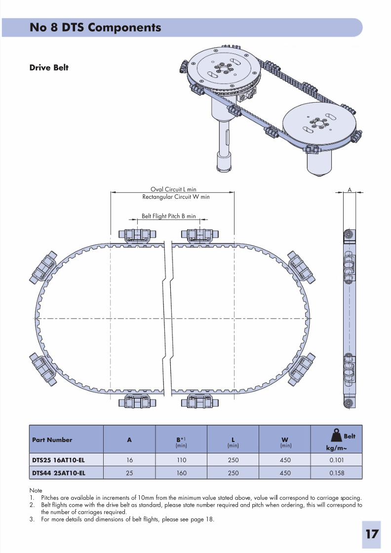
Drive Belt
Note1. Pitches are available in increments of 10mm from the minimum value stated above, value will correspond to carriage spacing.2. Belt flights come with the drive belt as standard, please state number required and pitch when ordering, this will correspond to
the number of carriages required.3. For more details and dimensions of belt flights, please see page 18.
Rectangular Circuit W minOval Circuit L min
Belt Flight Pitch B min
A
Part Number A B*1
(min)L
(min) W (min)
Belt
kg/m~
DTS25 16AT10-EL 16 110 250 450 0.101
DTS44 25AT10-EL 25 160 250 450 0.158
8/2/2019 No.8 DTS Components 02 UK.pdf
http://slidepdf.com/reader/full/no8-dts-components-02-ukpdf 18/19
No 8 DTS Components
18
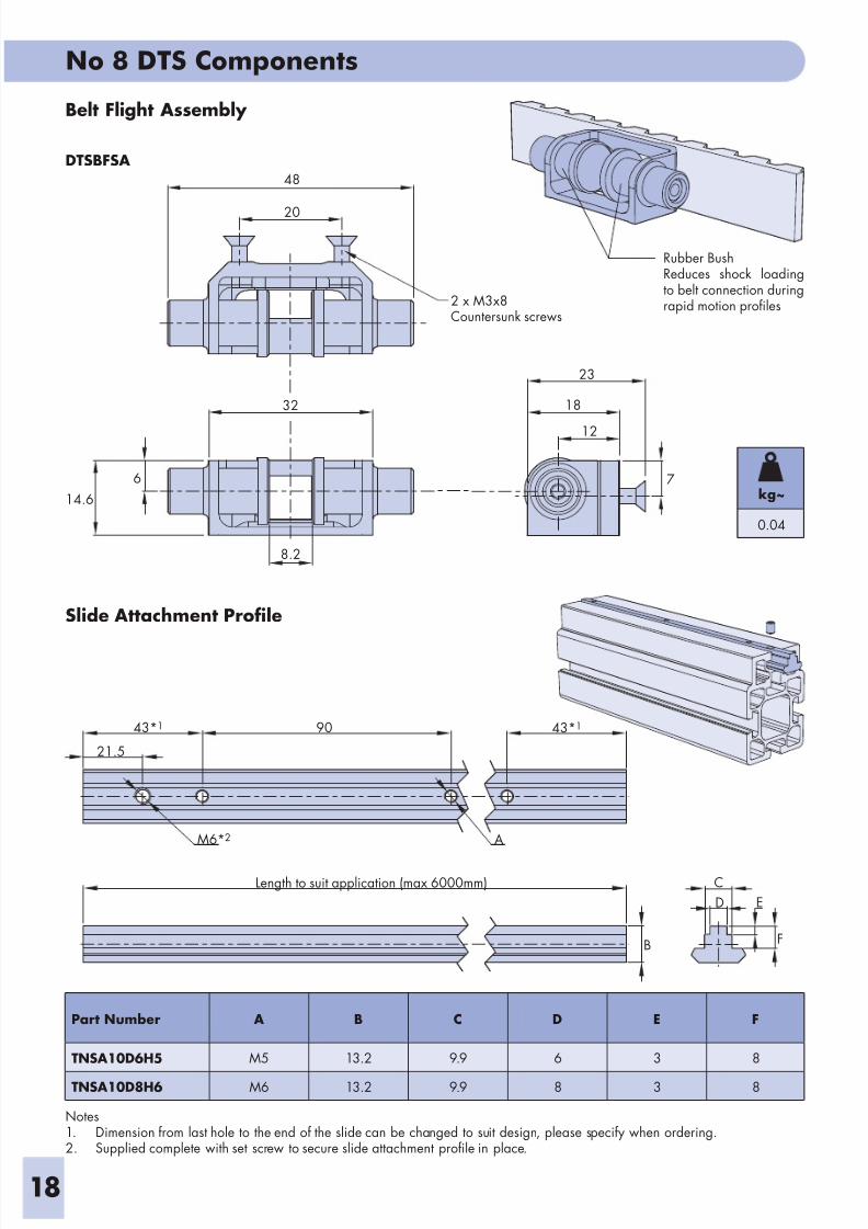
Slide Attachment Profile
Notes1. Dimension from last hole to the end of the slide can be changed to suit design, please specify when ordering.2. Supplied complete with set screw to secure slide attachment profile in place.
Belt Flight Assembly
DTSBFSA
Rubber BushReduces shock loadingto belt connection duringrapid motion profiles
18
23
12
32
14.6
6
20
48
7
8.2
2 x M3x8Countersunk screws
F
E
C
D
B
Length to suit application (max 6000mm)
43*1
21.5
M6*2
90
A
43*1
Part Number A B C D E F
TNSA10D6H5 M5 13.2 9.9 6 3 8
TNSA10D8H6 M6 13.2 9.9 8 3 8
kg~
0.04
8/2/2019 No.8 DTS Components 02 UK.pdf
http://slidepdf.com/reader/full/no8-dts-components-02-ukpdf 19/19
HepcoMotion®
, Lower Moor Business Park,Tiverton Way, Tiverton, Devon, England EX16 6TG
Tel: +44 (0) 1884 257000
Fax: +44 (0) 1884 243500
E mail: sales@hepcomotion com
No 8 DTS Components
Ordering detailsTo order any of the assemblies shown in this document, state the part number shown, followed by the quantity required. For moreinformation or advice with a particular application, please contact Hepco’s technical department.
Ordering Example
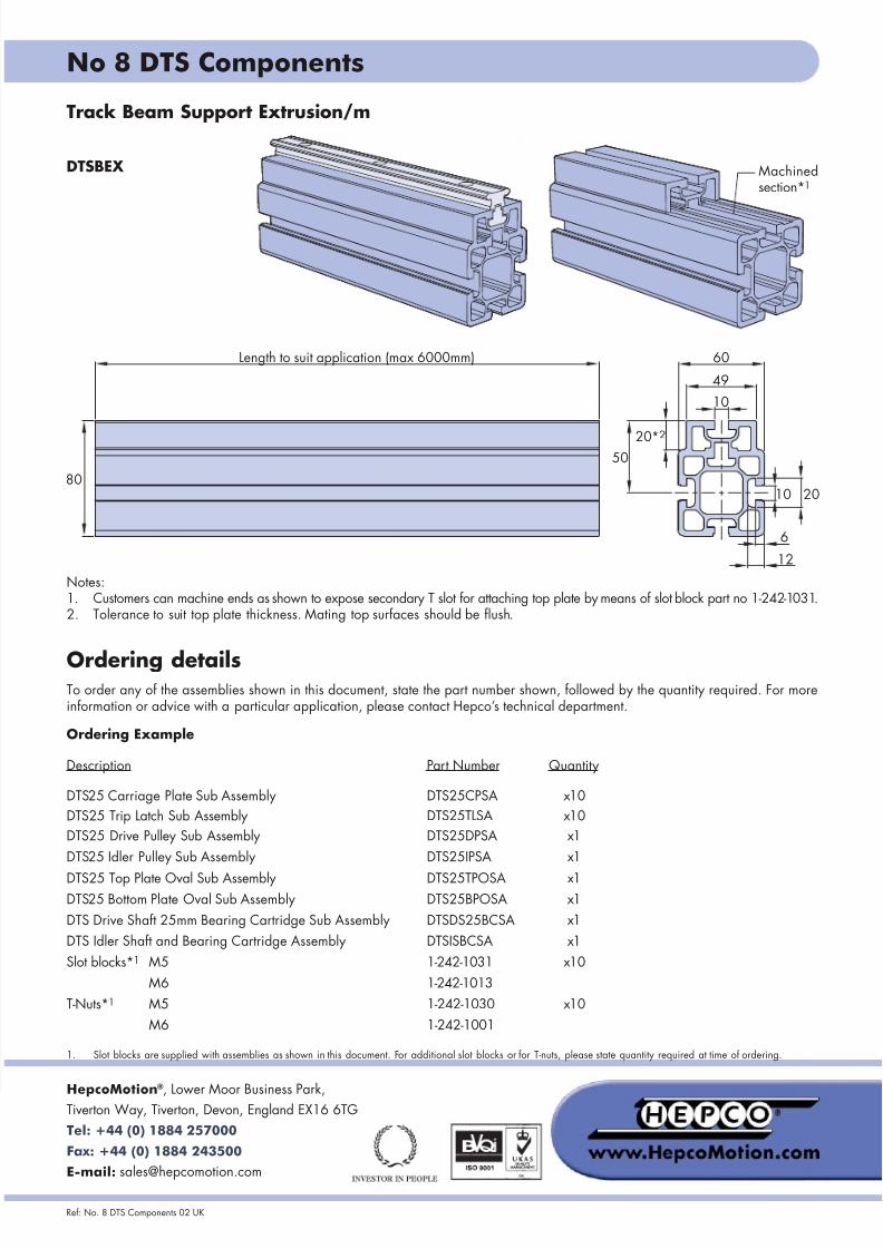
Track Beam Support Extrusion/m
DTSBEX
Part Number Quantity
DTS25CPSA
DTS25TLSA
DTS25DPSA
DTS25IPSA
DTS25TPOSADTS25BPOSA
DTSDS25BCSA
DTSISBCSA
x10
x10
x1
x1
x1x1
x1
x1
Machinedsection*1
Notes:1. Customers can machine ends as shown to expose secondary T slot for attaching top plate by means of slot block part no 1-242-1031.2. Tolerance to suit top plate thickness. Mating top surfaces should be flush.
Description
DTS25 Carriage Plate Sub Assembly
DTS25 Trip Latch Sub Assembly
DTS25 Drive Pulley Sub Assembly
DTS25 Idler Pulley Sub Assembly
DTS25 Top Plate Oval Sub AssemblyDTS25 Bottom Plate Oval Sub Assembly
DTS Drive Shaft 25mm Bearing Cartridge Sub Assembly
DTS Idler Shaft and Bearing Cartridge Assembly
T-Nuts*1 1-242-1030
x10
1. Slot blocks are supplied with assemblies as shown in this document. For additional slot blocks or for T-nuts, please state quantity required at time of ordering.
M6
M5
1-242-1001
Slot blocks*1
M5
M6
1-242-1031
1-242-1013
x10
80
Length to suit application (max 6000mm)
10
49
60
20*2
50
10 20
6
12
Related Documents