Nº20 MARINE POWER SUPPLY SYSTEMS DC DISTRIBUTION MONITORING DC POWER SUPPLY AC POWER SUPPLY AC DISTRIBUTION INSTALLATION CONNECTORS LED-LIGHTS

Welcome message from author
This document is posted to help you gain knowledge. Please leave a comment to let me know what you think about it! Share it to your friends and learn new things together.
Transcript

S Y S T E M E F Ü R D I E
S T R O M V E R S O R G U N G A N B O R D
S T R O M K R E I S V E R T E I L E R
Ü B E R W A C H U N G
S T R O M V E R S O R G U N G D C
S T R O M V E R S O R G U N G A C
S T R O M V E R T E I L U N G A C
I N S T A L L A T I O N
S T E C K V E R B I N D E R
L E D - B E L E U C H T U N G
Nº2
0
M A R I N E
P O W E R S U P P L Y S Y S T E M S
D C D I S T R I B U T I O N
M O N I T O R I N G
D C P O W E R S U P P L Y
A C P O W E R S U P P L Y
A C D I S T R I B U T I O N
I N S T A L L A T I O N
C O N N E C T O R S
L E D - L I G H T S

Pioneering spirit in yacht electrics - for more than 40 years
YEARS1978
2018
Are you planning a new construction or conversion of your boat? Or you want to equip a caravan for expeditions? We support you with the electrical equipment. A reliable power supply far away from land networks requires basic expertise. Because many technical compo-nents require precisely coordinated systems, for example through digital controlled systems or due to weight and space savings.
philippi equips you - with decades of experience and a comprehen-sive product range of electrical systems on yachts, sport boats and expedition mobile homes. Discuss your plans with us. We will
develop a tailor-made power supply concept for you and guarantee that all components work reliably together.
Our catalogue provides you with an overview. In eight clearly arranged product categories, we explain important technical rela-tionships with system examples and information panels. Whether yacht trip or off-road world tour - here you can find out everything about the individual integration of batteries and generators, distri-bution panels and battery chargers, solar cells as well as voltage converters and inverters with modern monitoring systems.
Reliable power supply is a major challenge away from the usual infrastructures. Anyone who moves at sea or in landscapes far removed from civilization is dependent on precise precautions. philippi has been developing charging, distribution and monitoring systems for yachts, sport boats, expedition motor homes and off-road vehicles for 40 years.
Please note: This catalogue is intended to provide advice to the best of our knowledge, and is not legally binding. The illustrations of the listed products and the wiring diagrams are not binding. We do not accept any liability for printing errors or incorrect information provided by mistake. We expressly reserve the right to adapt our products to the current technical status and to make changes.

N°
20
01
Connectors Connectors
Circuit breakers Sine wave inverters, combis
Connectors / Switches Main switches and relays
DC/DC-converters
Gensets
DC-Installation
LED-lights
Engineering made in Germany
To complete our product range we cooperate with well-known German and international companies. We favour companies producing to the highest standards and preferably their production site in the German speaking part, in order to get best quality products together with best technical assistance and knowledge in special details.
Quality made in Germany: as a Swabian family business we produce in our own factory according to the highest standards. Many components are manufactured and tested directly on site. In this way, we guarantee a complete, coordinated supply concept from
planning to delivery. Personal service is very important to us! This is what our employees stand for, from planning and order acceptance through production to delivery on your yacht or in your expedition vehicle.
Selected suppliers

N°
20
02
Responsibility according to European standards
Boat owners, service companies, trading companies and shipyards from all over Europe have been relying on the constantly high quality level of For us, this means the obligation to set standards not only in the development of great products, but also in technical standards. We have always fulfilled the guidelines and standards of VDE - EN ISO and Germanischer Lloyd. In addition, we are a permanent member of the standards committees of the boat industry. Due to our active participation in the German Boat and Shipbuilders Association (DBSV) and the Federal Association of the Water Sports Industry (BVWW), we are always up to date in terms of standards and regulations. And we share our knowledge. In 1996 we initiated the working group on yacht electrics and electronics in the DBSV.
All products marked with the CE mark comply with the valid and relevant legal regulations by European directives. Since 1996, for example, only devices that comply with the EMC directives may be placed on the market. With the CE mark philippi elektrische systeme gmbh declares that all products manufactured and distributed by us meet the European and national safety requirements for general product safety directive 2001/95/EC as well as the requirements for electromagnetic compatibility of electrical and electronic products directive 2014/30/EU of the European Parliament and Council and EMC Act. Warranty and liability claims under civil law are not regulated by this confirmation. The CE mark is not a quality mark and therefore says nothing about the quality of the products. In addition, we refer to the standard: Small watercraft - Electrical systems - alternating current and direct current systems DIN EN ISO 13297:2018 Please note our corresponding notes in the respective chapters.
The CE-Classification

N°
20
03
New Catalog Design On the following 112 pages we present our product range to you. Eight product categories are available for you thematically under- structured. An introductory page leads you to the respective topic and answers the first important questions. Colour bars mark the individual chapters - so you always know exactly where to find what. You will also find this colour code in info boxes on the pro-duct pages. Here we explain the technical background to the res-pective topic. We wish you informative reading. Michael Kögel and the -Team
Index
Our Perfomance Promise Functionality and Design All devices developed by us are characterized by functio-nality, modern design and safe, simple operation even in emergencies. Safety and Security In principle, we work in accordance with all relevant and necessary safety regulations and standards. This also applies to the selection of components. Service Life and Durability Conditions at sea and offroad place high demands on cor-rosion protection and vibration. In order to guarantee a long service life, we only use stainless materials such as aluminium, stainless steel, plastics and parts with tempered surfaces. Warranty Our products are guaranteed for two years. Even after expiration we are at your side with advice and action. Made in Germany All products manufactured by philippi are developed, manufactured and tested in our factory. In this way we guarantee a consistently high level of quality. Service If you have any questions about philippi on-board and vehicle electrics, please contact your specialist dealer. Of course, our employees are also available to answer your questions, technical problems or suggestions and wishes at any time.
l D C D I S T R I B U T I O N Power distribution panels series 200 . . . . . . . . . . . . . . . . . . . . . . .06 Accessories for Power Distribution Panels Series 200 . . . . . . . . . .13 Refit / Custom-made Panels . . . . . . . . . . . . . . . . . . . . . . . . . . . . . .14 Power Distribution Panels Series 100 . . . . . . . . . . . . . . . . . . . . . .16 Accessories for Power Distribution Panels Series 100 . . . . . . . . . .20 Power Distribution Panels, Watertight Series 700 . . . . . . . . . . . . .23 EnergyManagement-Box . . . . . . . . . . . . . . . . . . . . . . . . . . . . . . . . .26 l M O N I T O R I N G P-BUS System Monitors . . . . . . . . . . . . . . . . . . . . . . . . . . . . . . . . .31 P-BUS Battery / Temperature / Tank Monitoring . . . . . . . . . . . . . . . .36 P-BUS Battery Switching / Digital Switching . . . . . . . . . . . . . . . . . . .39 P-BUS Energy Monitoring . . . . . . . . . . . . . . . . . . . . . . . . . . . . . . . . .42 Battery Monitors . . . . . . . . . . . . . . . . . . . . . . . . . . . . . . . . . . . . . . .46 Tank Monitors . . . . . . . . . . . . . . . . . . . . . . . . . . . . . . . . . . . . . . . . .48 Tank Sensors . . . . . . . . . . . . . . . . . . . . . . . . . . . . . . . . . . . . . . . . .50 Bilge Pump Control . . . . . . . . . . . . . . . . . . . . . . . . . . . . . . . . . . . .53 Deep Discharge Protection . . . . . . . . . . . . . . . . . . . . . . . . . . . . . . .54 Navigation Lights Monitoring . . . . . . . . . . . . . . . . . . . . . . . . . . . . .55
l D C P O W E R S U P P L Y Battery Charger, Charging Monitor . . . . . . . . . . . . . . . . . . . . . . . . .58 B2B-Charger, Solar Charger . . . . . . . . . . . . . . . . . . . . . . . . . . . . . .63 DC/DC Converter . . . . . . . . . . . . . . . . . . . . . . . . . . . . . . . . . . . . . .64 Drop-free Battery Isolator . . . . . . . . . . . . . . . . . . . . . . . . . . . . . . . .65 Active Charging Relay, Charge Equalizer . . . . . . . . . . . . . . . . . . . . . .66 Lithium Battery Systems . . . . . . . . . . . . . . . . . . . . . . . . . . . . . . . . .67 GEL-, AGM- Batteries . . . . . . . . . . . . . . . . . . . . . . . . . . . . . . . . . . .68 l A C P O W E R S U P P L Y
Sine-Wave Inverter DC/AC . . . . . . . . . . . . . . . . . . . . . . . . . . . . . . .71 Inverter-Charger Combination . . . . . . . . . . . . . . . . . . . . . . . . . . . .72
l A C D I S T R I B U T I O N Shore Power Connection Units . . . . . . . . . . . . . . . . . . . . . . . . . . .76
Switch Over Units, Selector Switches . . . . . . . . . . . . . . . . . . . . . . .79 Shore Power Connection . . . . . . . . . . . . . . . . . . . . . . . . . . . . . . . .80 Isolating Transformer / Galvanic Isolator . . . . . . . . . . . . . . . . . . . .83
l I N S T A L L A T I O N Battery Main Switches . . . . . . . . . . . . . . . . . . . . . . . . . . . . . . . . . . .86
Remote Battery Main Switches . . . . . . . . . . . . . . . . . . . . . . . . . . . . .87 Fuse Blocks, Circuit Breakers, Strip Fuses . . . . . . . . . . . . . . . . . . .88 Terminal Blocks, BusBars, Terminal Bars . . . . . . . . . . . . . . . . . . . .95 Cable Termination, Crimping Tools . . . . . . . . . . . . . . . . . . . . . . . .98 Cables . . . . . . . . . . . . . . . . . . . . . . . . . . . . . . . . . . . . . . . . . . . . . 100 l C O N N E C T O R S Cable Clams . . . . . . . . . . . . . . . . . . . . . . . . . . . . . . . . . . . . . . . . .103 Round Plug Connectors Waterproof Series 692, 694 . . . . . . . . .104 Magnet-, Mini-Connectors . . . . . . . . . . . . . . . . . . . . . . . . . . . . . . .106 High Current Connectors, USB Sockets . . . . . . . . . . . . . . . .107 Connectors DC 12 V / 24 V . . . . . . . . . . . . . . . . . . . . . . . .108 Sockets and Switches . . . . . . . . . . . . . . . . . . . . . . . . . . . . . . . . .110 l L E D - L I G H T S Interior Illumination DC 12 V / 24 V . . . . . . . . . . . . . . . . . .112

07
21 23
Are you planning a new construction or refit of your yacht or vehicle? The safe and clear electrical distribution always plays an important role. The central element is the distribution panel. It has 3 functions for each circuit: switching on and off, circuit protection and function display. The type and size of the distribution panel usually depends on the installation conditions and the desired features. A little hint: plan with a little reserve - after all, many a device will be added later! We only use circuit breakers for circuit panel, no fuses! The advantage is obvious: after a short circuit has been rectified, the circuit breaker can simply be switched on again - no more searching for the right fuse...
The elegant panel for all occasions: The 3 functions switch, circuit breaker and display are combined in one high-quality com-ponent. A wide range of different panels with or without monitors and other components meet (almost) every installation situation and requirement. Fuse ratings from 2 to 20 A.
Distribution Panels Series 700
Distribution Panels Series 200
The panel for outside: the 3 functions switch, circuit breaker and LED display are united in a very high-quality component and above all: waterproof from the front.

26
14 16
CUSTOM MADE If the selection of distribution panels did not meet your requirements, you can also order special designs from us. These are made according to your requirements and can also include, for example, a heating control or operating panels from other manufacturers. In this case we provide the corresponding cut-outs so that you can integrate your other components into the panel.
It is the fully integrated switching and distribution unit for the "large" currents. Batteries, charger, alternator, solar and wind generators and large loads such as winches and inver-ters are connected directly. Simple & clear!
Our basic range: clear, inexpensive and proven for decades! The 3 functions: switch, circuit breaker and display are separated. Fuse ratings from 4A to 16A.
Distribution Panels Series 100
Energy Management-Box
DC Distribution

N°
20
06
i
k D C D I S T R I B U T I O N
The following points must be observed when planning and installing distribution panels: 1. The positive supply line to the distribution panel must be fused directly at the battery and fitted with a main switch. 2. As a general rule, the circuit breaker must be suitable for the respective conductor cross-section in order to protect the
cable against overheating and fire hazard - see table below. 3. The supply line must be dimensioned accordingly for the consumer/load. 4. A minimum cable cross-section of 1 mm² for single wires must be observed, fuse max. 6 A. 5. We recommend the use of 6 mm² cables for the supply of motor loads such as refrigerators or pumps. 6. For cable transitions we offer appropriate collecting points and terminal blocks. 7. Different amperages of circuit breakers: your desired configuration (within the scope of the available circuit breakers) can
be taken over with the order - without additional costs! 8. Circuit breakers can also be replaced at a later date and the fuse value increased / decreased. 9. If the cross-section of the supply line is reduced at the terminal bar to the circuit distributor, an additional fuse must be
installed there which matches the new conductor cross-section. See standard: Small craft - Electrical systems - AC and DC equipment DIN EN ISO 13297:2018
I n s t a l l a t i o n o f D i s t r i b u t i o n P a n e l s
Here is an example: For a luminaire circuit (12V) with 10 luminaires per 10 W (total 100 W), the max. current would be 8.33 A. In this case, a cable with 1.5 mm² must be used for a cable length of up to 10 m, together with a 10 A fuse. For longer supply lines (greater than 10 m), the next larger cable cross-section of 2.5 mm² must be used in order to avoid an excessively high voltage drop (>10 %) at the consumer. However, the fuse can be maintained with 10 A. Should one or more stronger luminaires nevertheless be connected, the fuse protection could be increased to 16 A for a cable with 2.5 mm². The fuse holders SHM and the multiple fuse holders BS 5045 and BS 5052, see page 89, are suitable for fusing when the cross-section of the panel supply cable has to be reduced.
CIRCUIT BREAKERS All philippi circuit breakers are equipped with thermal circuit breakers (series 200 and 700 with switching function). Thermal fuses in distribution panels are a thing of the past. The advantage of circuit breakers is that the circuit can be reactivated at any time after the fault has been rectified without having to change the fuse.
Recommended cross-sections for the consumer supply lines for a voltage drop of max. 10% with a 12V on-board system
Protection up to 10 m > 10 m 2 A 1 mm² 1 mm² 6 A 1 mm² 1,5 mm² 10 A 1,5 mm² 2,5 mm² 16 A 2,5 mm² 4 mm² 20 A 4 mm² 6 mm²

N°
20
07
n SKZ -D Order-No.: 0 2900 1600
n SKZ -Mobil (Automotive) Order-No.: 0 2900 1606
n SKZ -GB Order-No.: 0 2900 1602
n SKZ -NL Order-No.: 0 2900 1601
n SKZ -ES Order-No.: 0 2900 1603
n SKZ -DK Order-No.: 0 2900 1604
n SKZ -FR Order-No.: 0 2900 1605
n SKZ -PL Order-No.: 0 2900 1611
Circuit labels for panel series 200. Set of self adhesive labels, which can be
placed at each circuit breaker on the signed field. Included in delivery.
All information about the labels listed here on www.philippi-online.de
k D I S T R I B U T I O N P A N E L S S E R I E S 2 0 0
The distributon panels series 200 combine optimum ease of operation through the clearly structured design and the resulting simple operation with high-quality and reliable technology. The individual circuits are switched and fused via thermal circuit breakers of the E-T-A 3130 series. The integrated LED indicator light indicates the operating status of the circuit. The coordinated dimensions of the individual distributon panels allow any combination in horizontal or vertical direction. The panel cut-out for all models can be 10 mm smaller per edge than the panel dimensions.
Circuit breakers with a rated current of 10 A are installed ex works, 2 A, 6 A, 16 A or 20 A types can be used on request. The distribution panels can be used for DC 12V and 24V unless otherwise specified.
S E R I E S 2 0 0The connection is made via 6.3 mm flat connectors on the rear side of the circuit breakers. High-quality busbars made of nickel-plated copper connect the supply side of the circuit breakers. This ensures a safe current transition, especially in maritime environments.
A set with inscription labels (SKZ) and black fixing screws are supplied.
SAFE FUNCTION EVERYWHERE AND AT ANY TIME Control panels with thermal circuit breakers enable a very safe and reliable supply of the electrical system, as they do not require electronic components. They are the first choice for applications where maximum safety is essential. Even in installations that are already equipped with digital switching functions, circuit-breakers represent a safe basic supply for the safety-relevant functions.
The electronic position light monitor detects the failure of the incandescent lamp or light emitting diode (LED) or a cable interruption. In the event of a fault, the assigned LED on the display indicates the fault.
POSITION LIGHT CONTROL

N°
20
08 8 power circuits with thermal circuit breakers 10 A
Dimensions W 210 x H 105 x D 70 mm
Suitable terminal blocks type RKL 10
2 power circuits with thermal circuit breakers 10 A and display power boat incl.
electronic navigation lights monitor POS 6 with alarm, for use with LED -lanterns or
normal bulbs, for 12V and 24V
Dimensions W 210 x H 105 x D 70 mm
n STV 208 Order-No.: 0 2000 2080n STV 202 MS Order-No.: 0 2002 2026
10 power circuits with thermal circuit breakers 10 A. Dimensions W 105 x H 210 x D 70 mm Suitable terminal blocks type Type RKL 10.
7 power circuits with thermal circuit breakers 10 A, DC - and dual USB charging socket. Dimensions W 105 x H 210 x D 70 mm Suitable terminal blocks type Type RKL 10.
4 power circuits with thermal circuit breakers 10 A, display sailing yacht incl. electronic navigation lights monitor POS 6 with alarm, for use with LED -lanterns or normal bulbs, for 12V and 24V Dimensions W 105 x H 210 x D 70 mm
n STV 207 Order-No.: 0 2000 2071n STV 204 SY Order-No.: 0 2002 2041
7 power circuits with thermal circuit breakers 10 A, monitor BTM or PSM2 and 2 control switches for individual use. Shunt SHE (BTM) or P-BUS components have to be ordered separately!
Dimensions W 210 x H 157,5 x D 70 mm Suitable terminal blocks type RKL 10
n STV 237 (BTM) Order-No.: 0 2000 2370
n STV 247 (PSM2) Order-No.: 0 2000 2470
n STV 210 Order-No.: 0 2000 2100
k P O W E R D I S T R I B U T I O N P A N E L S S E R I E S 2 0 0
n STV 216 (TCS) Order-No.: 0 2000 2160
n STV 218 (BLS-Set) Order-No.: 0 2000 2180
7 power circuits with thermal circuit breakers 10 A, monitor TCS or BLS-Set. The shunt SHE 300 is included in the scope of delivery of the STV 218. Further information about the monitors on page 45ff. Dimensions W 105 x H 210 x D 70 mm Suitable terminal blocks type RKL 10

N°
20
09
n STV 200-5 Order-No.: 0 2000 2005n STV 204 Order-No.: 0 2000 2040n STV 203 Order-No.: 0 2000 2030
5 circuits with rocker switch (31,5x14 mm) and
lamp diodes display. Rocker switches can be
exchanged to other models, please see page 22.
Dimensions W 105 x H 105 x D 50 mm
20 power circuits with thermal circuit breakers 10 A
Dimensions W 210 x H 210 x D 70 mm
Suitable terminal blocks type RKL 20
3 power circuits with thermal circuit breakers
30 A.
Dimensions W 105 x H 105 x D 70 mm Suitable terminal blocks type RKL 10
4 power circuits with thermal circuit breakers
10 A.
Dimensions W 105 x H 105 x D 70 mm Suitable terminal blocks type RKL 10
14 power circuits with thermal circuit breakers 10A, volt- and ammeter (0-40 A),
3 control switches (0-1, 1-0-2, 1-2) for individual use.
Dimensions W 210 x H 210 x D 70 mm
Suitable terminal blocks type RKL 16/4
n STV 214 -12V Order-No.: 0 2001 2140
n STV 214 -24V Order-No.: 0 2002 2140
k P O W E R D I S T R I B U T I O N P A N E L S S E R I E S 2 0 0
n STV 220 Order-No.: 0 2000 2200
Panel for 2x PSD or USB sockets. Sockets have to
be ordered separately, please see page 107.
Dimensions W 105 x H 52,5 x D 70 mm
n MPE 202 Order-No.: 0 2800 2020
Panel for 3 parts: sockets series RTQ and / or
push button RDS.
Dimensions W 105 x H 52,5 x D 70 mm
n MPE 203 Order-No.: 0 2990 0203
n RTQ USB Order-No.: 6 0002 1002
USB 2.0 socket with USB-cable 30cm.
n RTQ LAN Order-No.: 6 0002 1008
Socket with 2x RJ45 sockets (front / rear).
n RDS 0-(1) Order-No.: 6 0002 0010
Push button 0-(1), Ring is green illuminated, 0,1A

N°
20
10
The circuit distributors STV 232, STV 235, STV 236, STV 238 and STV 244 can optionally be supplied with a battery/tank monitor BTM or the system monitor PSM2. Depending on the model, they enable complete protection and monitoring of a medium-sized sailing yacht or vehicle with one panel. Freely assignable control switches can be used to switch remotely
controllable main switches, bilge pump automatic, inverter control, loudspeaker switches and any other applications. The dual USB charging socket is suitable for 12 V and 24 V operating voltages. The shunt SHE for the monitor BTM and the P-BUS components for the monitors PSM2 and PSL have to be ordered separately, see page 30ff.
k P O W E R D I S T R I B U T I O N P A N E L S S E R I E S 2 0 0
14 power circuits with thermal circuit breakers 10 A, monitor BTM or PSM2, 1 DC- and 1 dual USB charging socket, 2 switches (0-1, 1-0-2) and display sailing yacht incl. navigation lights monitor POS 6 with alarm, Shunt SHE 300 /P-BUS Interfaces have to be ordered separately.
Dimensions W 315 x H 210 x D 70 mm
Suitable terminal blocks type RKL 16/4
n STV 236 (BTM) Order-No.: 0 2000 2360
n STV 256 (PSM2) Order-No.: 0 2000 2560
15 power circuits with thermal circuit breakers 10 A, monitor BTM or PSM2. Shunts /Interfaces have to be ordered separately. Dimensions B 210 x H 210 x T 70 mm
Suitable terminal blocks type RKL 16/4
n STV 235 (BTM) Order-No.: 0 2002 2350
n STV 255 (PSM2) Order-No.: 0 2002 2550
24 power circuits with thermal circuit breakers 10 A, monitor BTM or PSM2, 1 DC- and 1 dual USB charging
socket, 2 switches (0-1, 1-0-2) and display sailing yacht incl. navigation lights monitor POS 6 with alarm,.
Shunts /P-BUS Interfaces have to be ordered separately.
Dimensions W 420 x H 210 x D 70 mm
Suitable terminal blocks type RKL 30
n STV 244 (BTM) Order-No.: 0 2002 2440
n STV 264 (PSM2) Order-No.: 0 2002 2640
10 power circuits with thermal circuit breakers
10 A, monitor BTM or PSM2, 1 DC- and 1 dual
USB charging socket, 2 switches(0-1, 1-0-2).
Shunts /Interfaces have to be ordered separately.
Dimensions W 210 x H 210 x D 70 mm
Suitable terminal blocks type RKL 10
n STV 232 (BTM) Order-No.: 0 2000 2320
n STV 250 (PSM2) Order-No.: 0 2002 2500

N°
20
11
k P O W E R D I S T R I B U T I O N P A N E L S S E R I E S 2 0 0
14 power circuits with thermal circuit breakers 10 A, philippi system monitor PSL, DC- and dual USB charging
socket. Display sailing yacht incl. navigation lights monitor POS 6 with alarm,
Shunt and further P-BUS components have to be ordered separately !
Dimensions W 315 x H 210 x D 70 mm
Suitable terminal blocks type RKL 16/4
n STV 238 (BTM) Order-No.: 0 2000 2380
n STV 258 (PSM2) Order-No.: 0 2000 2580
7 power circuits with thermal circuit breakers
10 A, philippi system monitor PSL,
P-BUS components have to be ordered separately
Dimensions W 210 x H 157,5 x D 70 mm
Suitable terminal blocks type RKL 10
n STV 267 Order-No.: 0 2002 2670
24 power circuits with thermal circuit breakers 10 A, philippi system monitor PSL, DC- and dual USB charging
socket. Display sailing yacht incl. navigation lights monitor POS 6 with alarm, -
Shunt and further P-BUS components have to be ordered separately !
Dimensions W 420 x H 210 x D 70 mm
Suitable terminal blocks type RKL 30
n STV 284 Order-No.: 0 2002 2840
10 power circuits with thermal circuit breakers
10 A, philippi system monitor PSL, DC- and
dual USB charging socket.
Shunt and further P-BUS components have to be
ordered separately !
Dimensions W 210 x H 210 x D 70 mm
Suitable terminal blocks type RKL 10
n STV 270 Order-No.: 0 2002 2700
18 power circuits with thermal circuit breakers
10 A, monitor BTM or PSM2, display sailing yacht
incl. navigation lights control POS 6 with alarm,
1 switch 0-1. Shunt SHE 300 /P-BUS Interfaces
have to be ordered separately.
Dimensions W 210 x H 315 x D 70 mm
Suitable terminal blocks type RKL 20
n STV 274 Order-No.: 0 2002 2740

N°
20
12
Panel for hull isolation control. Double pole button
with 2 LEDs for testing. Hull will be isolated when
both LEDs are on while pressing the button.
For 12V / 24V.
Dimensions W 105 x H 52,5 x D 70 mm
n STV ISO Order-No.: 0 2000 0200
3 power circuits with thermal circuit breakers
10 A, double-pole
Dimensions W 105 x H 105 x D 70 mm
n STV 203-2p Order-No.: 0 2000 2032
To protect the circuits on aluminium and steel vessels, 2-pole circuit breakers are used for complete galvanic isolation from the ship's hull. The E-T-A 3130 2-pole circuit-breakers fit optically into the 200 series. The double pole panels series 200 can be combined with the distribution panels of the single pole series 200 as required because they have the same dimensions. The circuit breakers are available in 6 A, 10 A or 16 A current ratings. As standard thermal circuit breakers with a current of 10 A are installed. We recommend the RKL14 terminal blocks (two-pole) for this purpose.
14 power circuits with thermal circuit breakers 10A double -pole, system monitor PSL, display sailing yacht
incl. electronic navigation lights monitor POS 6 with alarm, hull isolation test.
Shunts and further P-BUS components have to be ordered separately!
Dimensions W 420 x H 210 x D 70 mm
Suitable terminal blocks type RKL 14
n STV 254-2p Order-No.: 0 2000 2542
12 power circuits with thermal circuit breakers
10 A, double pole.
Dimensions W 210 x H 210 x D 70 mm
Suitable terminal blocks type RKL 14
n STV 212-2p Order-No.: 0 2000 2122
k P O W E R D I S T R I B U T I O N P A N E L S D O U B L E P O L E
14 power circuits with thermal circuit breakers 10A double pole, monitor BTM or PSM2, display sailing yacht incl.
electronic navigation lights monitor POS 6 with alarm, 1 DC - and 1 dual USB charging socket and hull isolation
test. Shunt SHE (BTM) / P-BUS interfaces has to be ordered separately!
Dimensions W 420 x H 210 x D 70 mm
Suitable terminal blocks type RKL 14
n STV 234-2p (BTM) Order-No.: 0 2000 2342
n STV 254-2p (PSM2) Order-No.: 0 2000 2542
6 power circuits with thermal circuit breakers
10 A, double-pole .
Dimensions W 105 x H 210 x D 70 mm
Suitable terminal blocks type RKL 14
n STV 206-2p Order-No.: 0 2000 2062

N°
20
13
k A C C E S S O R I E S F O R P O W E R D I S T R I B U T I O N P A N E L S S E R I E S 2 0 0
Single pole DC: single pole rocker switch/thermal circuit breaker of compact design for snap-in panel mounting. Black with silver frame. Green LED. Cut out dimensions 14,8 x 34,2 mm, Width 18 mm. Rated voltage DC 30 V, Power consumption of the LED: 0,7 mA at 12 V
Circuit breakers available ex stock
n 3130-F11B-K7T1-W29AG3-2A Order-No.: 1 3130 2002
n 3130-F11B-K7T1-W29AG3-6A Order-No.: 1 3130 2006
n 3130-F11B-K7T1-W29AG3-10A Order-No.: 1 3130 2010
n 3130-F11B-K7T1-W29AG3-16A Order-No.: 1 3130 2016
n 3130-F11B-K7T1-W29AG3-20A Order-No.: 1 3130 2020
n 3130-F11B-L7T1-U29AG3-10A (Push button) Order-No.: 1 3130 4010
n 3130-F11B-K7T1-W29AG3-30A Order-No.: 1 3130 2030
(30 A: width like double pole version!)
Double pole DC: double pole rocker switch/thermal circuit breaker, green LED. Cut out dimensions 26,3 x 34,2 mm, Width 29,3mm, Rated voltage DC 30V. Current consumption of the LED: 0,7 mA at 12 V.
n 3130-F12B-S2T1-W29AG3-6A Order-No.: 1 3131 2006
n 3130-F12B-S2T1-W29AG3--10A Order-No.: 1 3131 2010
n 3130-F12B-S2T1-W29AG3--16A Order-No.: 1 3131 2016
n 3130-F12B-S2T1-U29AG3-10A (Push button) Order-No.: 1 3131 4010
Double pole AC 230 V: double pole rocker switch/thermal cb, red LED.
n 3130-F12B-S2T1-W24AR7-6A Order-No.: 1 3130 5006
n 3130-F12B-S2T1-W24AR7-10A Order-No.: 1 3130 5010
n 3130-F12B-S2T1-W24AR7-16A Order-No.: 1 3130 5016
n 3130-F15B-L7T1-W24AR7-20A Order-No.: 1 3130 5020
E-T-A 3130
k T H E R M A L C I R C U I T B R E A K E R S
Voltmeter DC
n SQB 8-16V Order-No.: 6 0490 0816
n SQB 16-32V Order-No.: 6 0490 1632
Tank gauge (DC 10-30V) for TGT/TGW
n SQB Water (10-180W) No.: 6 0490 9182
n SQB Fuel (10-180W) No.: 6 0490 9183
Ammeter DC (internal/external shunt)
n SQB 0-40A (internal) Order-No.: 6 0491 0040
n SQB 0-40A/60mV Order-No.: 6 0492 0040
n SQB 0-60A/60mV Order-No.: 6 0492 0060
n Shunt 40 A/60 mV Order-No.: 7 3060 0040
n Shunt 60 A/60 mV Order-No.: 7 3060 0060
Voltmeter AC (without illumination)
n SQB 250V (AC) Order-No.: 6 0495 0250
n Blank 200 Order-No.: 0 2900 2001 Dimensions W 105 x H 52,5 x D 2,5 mm
n Blank 201 Order-No.: 0 2900 2010 Dimensions W 105 x H 105 x D 2,5 mm
n Blank 202 Order-No.: 0 2900 2020 Dimensions W 210 x H 105 x D 2,5 mm
n Blank 204 Order-No.: 0 2900 2040 Dimensions W 210 x H 210 x D 2,5 mm n Blank 200 R Order-No.: 0 2900 2050 Blank panel for car radio with DIN-cut-out (183 x 55 mm) Dimensions W 210 x H 105 x D 2,5 mm
Blank panels
Analog precision meter with LED illumination More models available on request.
Dimensions W 48 x H 48 x D 46 mm
Cut-out W 45,5 x H 45,5 mm

N°
20
14
k B A V A R I A R E F I T P A N E L
Original-301-Panel m n Panel BAV 301 REFIT PSM2 Original-Panel m n After REFIT
The tank interface TIL #2 is additionally required if two waste water tanks are installed on board the Bavaria. Operation Voltage 10 – 32 V DC Power consumption 10 mA Dimensions W 130 x H 80 x D 42 mm
> TIL #2 Order-No.: 0 8000 1552
n BAV 301 REFIT BTM (incl. TIL) Order-No.: 0 3018 3011
n BAV 301 REFIT PSM2 Order-No.: 0 3018 3013
20 power circuits with thermal circuit breakers 10 A, monitor BTM or PSM2,
1 DC- and 1 dual USB charging socket, 2 switches for navigation lights.
Pre-assembled cable harness with multi-connector and accessories.
Shunt SHE /P-BUS components have to be ordered separately. Dimension Panel W 265 x H 210 x D 70 mm
In order to modernize the existing electrical system of Bavaria sailing yachts, we offer a replacement panel for the 301-Panel installed ex works. The exchange panel is pre-assembled with a cable harness to allow a simple and safe installation. The supplied tank interface TIL can be used to connect the prong probes of the water tanks installed ex works to the battery-tank monitor BTM. Via an optional battery management shunt SHE 300, the integrated monitor BTM can take over battery monitoring. The shunt is installed close to the house batteries, which are usually located under the
saloon benches. By connecting an ACE series charger in conjunction with an ACE-LIN interface, the BTM monitor can be upgraded to a fully-integrated battery charge management system. Alternatively, the panel can be equipped with a system monitor PSM2 . This allows all expansion options of the P-BUS system. The adaptation of the prong probes is done via a modified tank interface, please contact us. If you`re searching for other Bavaria panels, please ask.
The tank interface TIL adapts the signals from two fresh water and one waste water prong probe to the battery tank monitor BTM (included).

N°
20
15
If you are planning a new building or a conversion of your ship or vehicle, we are happy to assist you with the electrical equipment helpful to the side. We have decades of experience in the field of electrical installations on yachts, sport boats, in motor homes and expedition vehicles. With our comprehensive product range, we are able to supply all required components. This means that you receive the complete system from one source, from planning to delivery, and have the guarantee that every-thing is coordinated. As we are constantly involved in the standardi-sation committees of the boat industry, we are always up to date with regard to possible changes in standards and regulations. A central component of this planning is the creation of an individual special distribution panel, which is optimally aligned to your requirements.
This can be distribution panels for power supply with DC 12/24 V or AC 230 V /400 V- Trade on-board voltage. engine panels, distribution panels for outdoor use and for large 230 V-plants as well as complete control cabinets are also planned and manufactured.
Based on the technology of our distribution panels and land connection units, the illustra-tions show special designs of switchgear. The individual circuits are marked with special print or adhesive labels. For navigation lights monitoring, the drawing of the customer's ship can also be applied. We supply custom-made distribution panels and instrument panels in all dimensions, shapes and colour variants. Installation- complete systems consisting of l Shore power connection l Distribution switch circuits l Analogue gauges/ digital monitors
for batteries, tanks, battery chargers l Sockets and switches l Cut-out for special components
k R E F I T / C U S T O M M A D E P A N E L S
On the internet you will find a questionnaire about the preparation of an offer.
In order to submit a quotation as well as for the design and manufacture of these circuit distribution panels we require exact details regarding the requirement on board.
Before Refit After Refit

N°
20
16
The electronic navigation lights monitor POS 6 supervises up to 6 navigation light circuits and recognises each failure of a bulb or LED or the break of the cables. Each navigation light will be shown by a relating control LED on the panel. The failure of a lantern will be announced by an optical and an acoustic alarm, which can be acknowledged. The relating diode will be blinking on the display. Both normal bulbs and LED lights can be supervised, even mixed.
k P O W E R D I S T R I B U T I O N P A N E L S S E R I E S 1 0 0
SERIES 100
Power distribution switch panels in a build-up system for individual switching installations for ship's supply. Standard circuit breakers with
a nominal power rating of 8A are fitted. Circuit breakers with nominal power rating of 4A/6A/8A/10A/12A/16A may be fitted upon
request or supplied for later fitting. STKZ self-adhesive labels (165 per page) are included. The power distribution unit is supplied wired for
12V/24V with the relevant cable diameter. The connection is made with flat spade terminals 6.3 mm on the back of the unit.
The dimensions of the power distribution panels
are matched to each other to allow the choice
of horizontal or vertical combination.
Set of labels “STKZ” Self-adhesive labels will be provided
(see page 19)
Circuit breakers with nominal power rating of
4A/6A/8A/10A/12A/16A may be easy exchanged later on
The connection is made with flat spade terminals 6.3 mm on the rear side of
the unit

N°
20
17
k P O W E R D I S T R I B U T I O N P A N E L S S E R I E S 1 0 0
1 power circuit with thermic circuit breaker (8 A), lamp diode display, rocker switch. Dimensions W 110 x H 36,2 x D 70 mm
n STV 101 Order-No.: 0 2000 1010
3 power circuits with thermal circuit breakers (8 A), lamp diodes display, rocker switches. Dimensions W 110 x H 72,5 x D 70 mm Suitable terminal blocks type RKL 10
n STV 103 Order-No.: 0 2000 1030
6 power circuits with thermal circuit breakers (8 A), lamp diodes display, rocker switches. Dimensions W 110 x H 117 x D 70 mm Suitable terminal blocks type RKL 10
5 power circuits with thermal circuit breakers (8A), lamp diodes display, rocker switches, DC- and dual USB charging socket. Dimensions W 110 x H 145 x D 70 mm Suitable terminal blocks type RKL 10.
n STV 106 Order-No.: 0 2000 1060
n STV 105 Order-No.: 0 2000 1050
Voltmeter with switch over for service- und starter battery as addition to switch boards series STV 100. Dimensions W 110 x H 72,5 x D 80 mm
n PV -12 V Order-No.: 0 2801 0120
n PV -24 V Order-No.: 0 2802 0120
10 power circuits with thermal circuit breakers (8 A), lamp diodes display, rocker switches. Dimensions W 110 x H 180 x D 70 mm Suitable terminal blocks type RKL 10
n STV 110 Order-No.: 0 2000 1100
Recommended wires cross section for consumers supply lines Circuit breaker A 6 10 16 20 Wire mm2 1,0 1,5 2,5 4
6 power circuits with thermal circuit breakers (8A), lamp diodes display, rocker switches and protected small socket with protective cap. Dimensions W 110 x H 145 x D 70 mm Suitable terminal blocks type RKL 10.
8 power circuits with thermal circuit breakers (8 A), lamp diodes display, rocker switches. Dimensions W 110 x H 145 x D 70 mm Suitable terminal blocks type RKL 10
n STV 106/1 Order-No.: 0 2000 1061n STV 108 Order-No.: 0 2000 1080

N°
20
18
8 power circuits with thermal circuit breakers (8 A), lamp diodes display, rocker
switches, LED illuminated voltmeter with switch over 1-0-2.
Dimensions W 220 x H 117 x D 90 mm
Suitable terminal blocks type RKL 10
n STV 118 -12 V Order-No.: 0 2001 1180
n STV 118 -24 V Order-No.: 0 2002 1180
12 power circuits with thermal circuit breakers (8 A), lamp diodes display, rocker
switches, LED illuminated voltmeter with switch over 1-0-2.
Dimensions W 220 x H 145 x D 90 mm
Suitable terminal blocks type RKL 16/4
n STV 412 -12 V Order-No.: 0 2001 4120
n STV 412 -24 V Order-No.: 0 2002 4120
k P O W E R D I S T R I B U T I O N P A N E L S S E R I E S 1 0 0
Combined power distribution panel with navigation lights monitor for sailing yachts, 12 power circuits with thermal circuit breakers (8 A), lamp diode display, rocker switches as well as 4 additional circuit breakers (8 A), voltmeter with switch over, moving coil gauge, class 1.5. Display "Sloop" with electronic monitor POS 6.
Dimensions W 330 x H 145 x D 70 mm
Suitable terminal blocks type RKL 16/4
n STV 312/4 -SY -12 V Order-No.: 0 2501 3120
n STV 312/4 -SY -24 V Order-No.: 0 2502 3120
11 power circuits with thermal circuit breakers (8 A), lamp diodes display, rocker switches as well as 5 additional thermal circuit breakers (8 A). Voltmeter with switch over 1-0-2, moving coil gauge, class 1,5.
Dimensions W 220 x H 145 x D 70 mm
Suitable terminal blocks type RKL 16/4
n STV 311/5 -12 V Order-No.: 0 2001 3115
n STV 311/5 -24 V Order-No.: 0 2002 3115
16 power circuits with thermal circuit breakers (8 A), lamp diodes display and rocker switches.
Dimensions W 220 x H 145 x D 70 mm
Suitable terminal blocks type RKL 16/4
n STV 316 Order-No.: 0 2000 3160
n STV 312 (TCS) Order-No.: 0 2002 3120
n STV 314 (BLS-Set) Order-No.: 0 2002 3140
12 power circuits with thermal circuit breakers (8 A), lamp diodes display and
rocker switches. Monitor TCS or BLS-Set. The shunt SHE 300 is included in the
scope of delivery of the STV 314. Further information on page 45ff.
Dimensions W 220 x H 145 x D 70 mm
Suitable terminal blocks type RKL 16/4

N°
20
19
k P O W E R D I S T R I B U T I O N P A N E L S S E R I E S 1 0 0
n STV 088 Order-No.: 0 2000 0880 n STV 08 Order-No.: 0 2000 0080
n POS -MY Order-No.: 0 2500 0005n POS -KY Order-No.: 0 2500 0001n POS -SY Order-No.: 0 2502 0000
For VHF devices with a double pole circuit breaker with integrated lamp diode (10 A). Dimensions W 65 x H 50 x D 60 mm
n UKW 3130 Order-No.: 0 2000 0502
8 thermal circuit breakers 8 A Dimensions W 75 x H 145 x D 60 mm Suitable terminal blocks type RKL 10.
8 rocker switches Dimensions W 46 x H 145 x D 30 mm
Coated aluminium panel with yacht diagram - “Power boat” and electronic navigation lights monitor POS 6. Dimensions W 145 x H 110 x D 25 mm
Coated aluminium panel with yacht diagram - sailing yacht “Ketch/Yawl” and electronic navi-gation lights monitor POS 6.
Dimensions W 110 x H 145 x D 25 mm
Coated aluminium panel with yacht diagram - sailing yacht “Sloop” and electronic navigation lights monitor POS 6. Dimensions W 110 x H 145 x D 40 mm
Blank panels for covering larger cut-outs and individual panels. Plastic-coated aluminium board with 4 mounting holes.
n Blank panel Leer 103 Order-No.: 0 2900 1030 Dimensions W 110 x H 72,5 x D 2 mm n Blank panel Leer 108 Order-No.: 0 2900 1080 Dimensions W 110 x H 145 x D 2 mm
n Blank panel Leer 316 Order-No.: 0 2900 3160 Dimensions W 220 x H 145 x D 2 mm
Blank panels Power circuit labels
All information about the labels listed here on www.philippi-online.de
Power circuit labels for individual power circuits mounted on panels. Self adhesi-ve watertight vinyl foil. 165 different signs in languages German, Dutch, English, French, Dansk, Polish, Italian (only 62 labels). Dimensions 27 x 8 mm.
n STKZ - D Order-No.: 0 2900 1650
n STKZ - NL Order-No.: 0 2900 1651
n STKZ - GB Order-No.: 0 2900 1652
n STKZ - I Order-No.: 0 2900 1653
n STKZ - DK Order-No.: 0 2900 1655
n STKZ - PL Order-No.: 0 2900 1656
n STKZ - F Order-No.: 0 2900 1657

AU
S ¿ 4,2
1134
,5
19
N°
20
20
LED 10 mm
E-T-A 1140-F114-P1-M1
LED 5 mm LED 3 mm
k A C C E S S O R I E S F O R P O W E R D I S T R I B U T I O N P A N E L S S E R I E S 1 0 0
Single pole thermal circuit breaker with push-to-reset, failsafe, trip-free (EN 60934). Snap-in type. Cut out measurement: 22 x 11.3 mm. Rated voltage DC 48 V, AC 240 V. Current ratings 4...16 A Circuit breakers available ex stock
n ETA 1140-F114-P1-M1-4A Order No.: 1 1140 0004
n ETA 1140-F114-P1-M1-6A Order No.: 1 1140 0006
n ETA 1140-F114-P1-M1-8A Order No.: 1 1140 0008
n ETA 1140-F114-P1-M1-10A Order No.: 1 1140 0010
n ETA 1140-F114-P1-M1-12A Order No.: 1 1140 0012
n ETA 1140-F114-P1-M1-16A Order No.: 1 1140 0016
Lamp diodes with minimal power consumption of 7 mA. (12V) / 16 mA (24V). Connectable directly to 12/24V (DC 30V). Fitting hole: l 10 mm
n LED 10 mm, red Order No.: 6 0005 1000
n LED 10 mm, yellow Order No.: 6 0005 1010
n LED 10 mm, green Order No.: 6 0005 1020
Lamp diodes with minimal power consumption of 4 mA (12 V) / 8 mA (24 V). Connectable directly to 12/24V (DC 30V). Fitting hole: l 6,2 mm
n LED 5 mm, red Order No.: 6 0005 0600
n LED 5 mm, yellow Order No.: 6 0005 0610
n LED 5 mm, green Order No.: 6 0005 0620
Lamp diodes with minimal power consumption of 6 mA (12V) and 12mA (24V). Connectable directly to 12/24V (DC 30V). Fitting hole: l 4,2 mm
n LED 3 mm, red Order No.: 7 0000 3050
n LED 3 mm, yellow Order No.: 7 0000 3051
n LED 3 mm, green Order No.: 7 0000 3052
Starter lock (0 - Ignition - Start) for combustion engines with 2 keys mit 2 Schlüsseln. Depth 59 mm, hole-l 18 mm
Splash-proof pushbutton with short threaded shaft, dimensions 47 x l 27 mm, assembly hole l 22 mm, max. wall thickness 6 mm. Current carrying capacity 20 A. Degree of protection IP55.
Splash-proof pushbutton with long threaded shaft, dimensions 72 x l 28 mm, assembly hole l 14 mm, max. wall thickness 12 mm. Current carrying capacity 30 A. Degree of protection IP55.
n DT 12/24 K sw Order No.: 7 6014 8600
n DT 12/24 K rt Order No.: 7 6014 8601
n DT 12/24 L sw Order No.: 7 6014 8480
n DT 12/24 L rt Order No.: 7 6014 8481n ZSD Order No.: 6 0018 0027
Lamp diodes for AC 230V/50Hz. SL 9: Fitting hole l: 8 mm. Cable length 20 cm. LED 10: hole-l: 10 mm. connector 2,8 mm.
n SL 9 red (AC 230 V) Order No.: 6 0009 0557
n LED 10 mm, AC red Order No.: 6 0009 0028
n LED 10 mm, AC yell. Order No.: 6 0009 0128
LED AC 230 V

N°
20
21
k A C C E S S O R I E S F O R P O W E R D I S T R I B U T I O N P A N E L S S E R I E S 1 0 0
n MAD Order No.: 7 0010 1732 n MTD Order No.: 7 0010 1741
Very small DC temperature meter with OLED
display, easy to read in daylight.
Front side waterproof IP66.
•Range -40 - +120°C,
•Own consumption 10 mA.
•Delivery incl. temperature sensor
•Mounting hole Ø 29 mm, OuterØ 40 mm,
depth 54 mm
Very small DC ammeter with OLED display,
easy to read in daylight.
Front side waterproof IP66.
•Range -100 - 0 - +100 A,
•Own consumption 15 mA.
•Delivery incl. shunt
•Mounting hole Ø 29 mm, OuterØ 40 mm,
depth 54 mm
Precision measuring instruments with coil cores for direct current and moving coil SQE for alternating current (Class 1.5), in contrast to the normally used instruments in the marine industry, are more precise and have an own consumption of only 1 mA. Dimensions W 48 x H 48 x D 46 mm
Cut-out W 45,5 x H 45,5 mm
Analogue marine gauges with integrated LED-illumination. Watertight front part. Fitting hole l 52 mm, outer diameter l 58 mm. For the use at 24 V rated voltage a pre-resistor Rturo is needed for some gauges. Matching tank gauges: Water / Fuel / Waste Water please see page 51.
VOLTMETER DC
n SQS 48 /8-16 V Order No.: 6 0480 0816
n SQS 48 /16-32 V Order No.: 6 0480 1632
AMMETER DC
n SQS 48 /0-25 A Order No.: 6 0481 0025
n SQS 48 /0-40 A Order No.: 6 0481 0040
VOLTMETER AC
n SQE 48 /0-250 V AOrder No.: 6 0485 0250
VOLTMETER DC
Rated voltage 12 V or 24 V, Own consumption max. 65 mA/12 V or max. 32 mA (24 V), installation depth 76 mm
n 8-16 Volt Order No.: 2 0774 0611
n 16-32 Volt Order No.: 2 0774 0801
OPERATING HOURS COUNTER The hours meter indicates the effective working time of the engine from starting until stop. With LED illumination. Nominal voltage 12/24 V, power consumption 5 mA/14 V, Scale range: 0-99999,9 h, installation depth 83 mm
n Hours 52 Order No.: 2 0761 0461
Very small DC voltmeter with OLED display,
easy to read in daylight.
Front side waterproof IP66.
•8-36 V DC, resolution 0,01 V, max. 13 mA
•Reverse polarity protected
•Mounting hole Ø 29 mm, OuterØ 40 mm,
depth 54 mm
n MVD Order No.: 7 0010 1733
Size comparison of the different instruments:

N°
20
22
n Lever switch 0-1 5 1821 1101
n Protective cap 5 3430 1023
Dimensions 21 x 15 mm. Hole l. 12 mm, spade terminals 4.8 mm.
Power control light AC 230 V/50 Hz.
Dimensions 31,5 x 14 mm.
n SL230 rt Order-No.: 5 1837 3102
n SL230 gr Order-No.: 5 1837 3108
Splashproof rocker switch l 25 mm (IP65). Max. current 10A, Inst. hole l 20,2 mm, spade terminals 4,8 mm
Rocker switch Order-No.:
n WIP 25 5 2013 0112
n WIP 25 RD 12V (red LED) 5 2013 0210
n WIP 25 GN 12V (green LED) 5 2013 0212 Lever switch Order-No.:
Panel without switch. Dimensions as above.
n Panel 66/50 Order-No.: 0 2991 0018
Panel without switch. Dimensions as above.
n Panel 66/40 Order-No.: 0 2990 6640
Panel without switch. Dimensions as above.
n Panel 66/25 Order-No.: 0 2990 6625
n ZSK 15 Order-No.: 5 0031 0104
Push-pull switch with a long tread shank.
Dimension-58 x l 14 mm (knob), Inst. hole l 8
mm. Wall thickness max.14 mm.Power load 15A.
n Lever switch chrome 0-1 5 0031 6838
n Lever switch chrome (1)-0-(2) 5 0031 6592
n Lever switch chrome 1-0-2 5 0031 6594
Two-pole lever switch (15 A) with chrome lever. Hole l 12 mm, spade terminals 6.3 mm.
Lever switch chrome Order-No.:
Rated current 10 A Panel 30 x 30 mm Depth 50 resp. 63 mm
Selector switch Order-No.:
n CG 4 A 241 (0-1-2-3) 6 4004 2410
n CG 4 A 232 (0-1-2-3-4) 6 4004 2320
Rocker switch IP65 Order-No.:
n Switch off 0-1 5 1932 3112 n Ch-over switch 1-0-2 5 1939 3119 n Ch-over button (1)-0-(2) 5 1939 3312
2-poles of spray water protected rocker switches 33 x 25 mm. Enclosure IP65, installation cut-out 30 x 22 mm, spade terminals 6.3 mm, max 20A
n Switch off ilum. 230 V 0-1 5 1830 3112 n Switch off 0-1 5 1831 3312 n Touch button 0-1 5 1831 3402 n Ch-over switch 1-2 5 1833 3302 n Ch-over switch 1-0-2 5 1838 3502 n Ch-over switch 1-0-(2) 5 1838 1602 n Ch-over switch (1)-0-(2) 5 1838 3402
Single-pole change-over button 31.5 x 14 mm. Cut-out 30 x 11 mm, spade terminals 6,3mm
n Switch off 0-1 5 1801 1102 n Touch button 0-1 5 1801 1202 n Ch-over switch 1-2 5 1803 1102 n Ch-over switch 1-0-2 5 1808 1103 n Ch-over switch 1-0-(2)touch 5 1808 1202 n Ch-over switch (1)-0-(2) 5 1808 1302 n Protective cap 5 2308 9011
Single-pole change-over button 21x 15 mm. Cut-out 19 x 13 mm, spade terminals 4.8 mm
Rocker switch 31,5 x 14 Order-No.: Rocker switch 21 x 15 Order-No.:
Plastic coated assembly plates for 2-pole press switch 33 x 25 mm. Dimensions W 50 x H 46 x D 50 mm
n STV 066/50 sw Order-No.: 0 2800 6650
Plastic coated assembly plates for 1-pole rocker switch 31,5 x 14 mm. Dimensions W 46 x H 40 x D 40 mm
n STV 066/40 sw Order-No.: 0 2800 6640
Plastic coated assembly plates for 1-pole rocker switch 21 x 15 mm. Dimensions W 46 x H 25 x D 30 mm
n STV 066/25 sw Order-No.: 0 2800 6625
k A C C E S S O R I E S F O R P O W E R D I S T R I B U T I O N P A N E L S S E R I E S 1 0 0

N°
20
23
k W A T E R T I G H T P O W E R D I S T R I B U T I O N P A N E L S E R I E S 7 0 0
Watertight switching units are advised for external use upon yachts . Mostly only watertight on-off switches are offered for this purpose, the required safety elements, which are usually mounted separately, are located in the protected interior of the yachts. The power distribution panels series 700 allow directly switching and
protection from the same device at the cockpit. Therefore is no longer the need to install cables and direct them to circuit breakers that are installed somewhere internally. Circuit breakers are available in 6 A, 10 A, 16 A, 20 A or as push button in 10A. Also there are three position switches and three position push buttons available (but these are not protected).
The circuit breakers have an internal function control light with a special switchable night illu-mination. During circuit supply the control light is on. The symbols are drawn with laser to make them impermiable to all types of weather.
In order to label each power circuit individually each actuator will be clipped on at his position. Therefore please order the activators separately.
The panels are mounted on the reverse side with threaded studs. The supplied gasket is for water proof mounting.
S E R I E 7 0 0

N°
20
24
Watertight panel with 12 circuit breakers 10 A. Mounting via screws from the front.
Actuators have to be ordered separately. Please see page 25.
Dimensions W 329 x H 69 x D 65 mm
n STV 722 Order-No.: 0 2000 7220
Watertight panel with 5 thermal circuit breakers
10 A, incl. gasket.
Actuators have to be ordered separately.
Please see page 25.
Dimensions W 147 x H 69 x D 65 mm
Watertight panel with 3 circuit breakers 10 A and
cigarette socket 21 mm, incl. gasket.
Actuators have to be ordered separately.
Please see page 25.
Dimensions W 147 x H 69 x D 65 mm
Watertight panel with 3 circuit breakers 10 A and
voltmeter MVD incl. gasket.
Actuators have to be ordered separately.
Please see page 25.
Dimensions W 147 x H 69 x D 65 mm
Watertight panel with 3 thermal circuit breakers
10 A, incl. gasket.
Actuators have to be ordered separately.
Please see page 25.
Dimensions W 95 x H 69 x D 65 mm
Watertight panel with 1 thermal circuit breaker
10 A, incl. gasket.
Actuator has to be ordered separately.
Please see page 25.
Dimensions W 43 x H 69 x D 65 mm
n STV 715 Order-No.: 0 2000 7150
n STV 714 Order-No.: 0 2000 7140
n STV 714V Order-No.: 0 2000 7145
n STV 713 Order-No.: 0 2000 7130 n STV 711 Order-No.:0 2000 7110
k W A T E R T I G H T P O W E R D I S T R I B U T I O N P A N E L S E R I E S 7 0 0
Alignable frame for circuit breakers series 3131 consisting of side- and middle- module. Minimum cut- out for
2 side - modules: W 51,2 x H 48,3 mm; a middle module spreads the complete frame width by 26,2 mm each.
Dimensions: side module: W 35 x H 68 mm, middle module: W 26,2 x H 68 mm
n 3131-MRS (Side module) Order-No.: 1 3087 9001
n 3131-Blind (Blind cap Order-No.: 1 3087 9999
n 3131-MRM (Middlel module) Order-No.: 1 3087 9101
Outdoor socket panel made of UV-resistant polycarbonate with a 15 A circuit
breaker, DC and USB double charging socket and DC voltmeter MVD including
seal.
Dimensions W 168 x H 57,2 x D 70 mm
n BS 4366 Order-No.: 7 0010 4366
Outdoor socket panel made of UV-resistant polycarbonate with a 15 A circuit
breaker, DC and USB double charging socket including seal.
Dimensions W 125,5 x H 57,2 x D 65 mm
n BS 4363 Order-No.: 7 0010 4363

N°
20
25
Watertight buzzer for 12 V / 24 V, IP68. Rotating
bezel adjusts alarm volume in a wide range.
•Operating current: 5 mA (12 V)/12 mA (24 V)
•Mounting hole: Ø 29 mm
•Outer diameter: Ø 35 mm
n SUM 29 Order-No.: 7 0010 1070 n USD EK Order-No.: 7 0010 1039
n Spray nozzle Order-No.: 1 2222 8820
n Searchlight Order-No.: 1 2222 8823
n Autopilot Order-No.: 1 2222 8824
n Trim tab Order-No.: 1 2222 8825
n Sailing boat position lights Order-No.: 1 2222 8827
n Sailing boat cock pit illumination Order-No.: 1 2222 8828
n Sailing boat deck illumination Order-No.: 1 2222 8829
n Sailing boat anchor light Order-No.: 1 2222 8830
n Socket Order-No.: 1 2222 8841
n Blue light Order-No.: 1 2222 8842
n Underwater illumination Order-No.: 1 2222 8870
n Bimini illumination Order-No.: 1 2222 8871
n Step illumination Order-No.: 1 2222 8872
n Stern flap Order-No.: 1 2222 8873
n Main sail Order-No.: 1 2222 8874
n Winch Order-No.: 1 2222 8875
n ON / OFF Order-No.: 1 2222 8877
n Lift Order-No.: 1 2222 8878
n Seat inclination Order-No.: 1 2222 8879
n Seat forwards/backwards Order-No.: 1 2222 8880
n Neutral Order-No.: 1 2222 8201
n Power boat interior illumination Order-No.: 1 2222 8801
n Power boat anchor light Order-No.: 1 2222 8802
n Power boat cockpit illumination Order-No.: 1 2222 8803
n Power boat position lights Order-No.: 1 2222 8804
n Power boat bow lantern Order-No.: 1 2222 8843
n VHF Order-No.: 1 2222 8805
n Refrigerator Order-No.: 1 2222 8806
n Anchor winch control Order-No.: 1 2222 8807
n Anchor winch up/down Order-No.: 1 2222 8844
n Wind screen wiper Order-No.: 1 2222 8808
n Bilge pump Order-No.: 1 2222 8809
n Fresh water pump Order-No.: 1 2222 8810
n Horn Order-No.: 1 2222 8811
n Ventilation Order-No.: 1 2222 8812
n Instruments illumination Order-No.: 1 2222 8813
n Navigation instruments Order-No.: 1 2222 8814
n Radio / Tuner Order-No.: 1 2222 8815
n Heating system Order-No.: 1 2222 8816
n Shower pump Order-No.: 1 2222 8817
Actuators for circuit breakers series E-T-A 3131 / STV700
Circuit breakers series E-T-A 3131
Snap in single pole on/off circuit breaker, water tight (IP 66) with overload protection
and LED control and nightlight Three position switches without protection (max. 20A)!
Cut-out dimensions:37 x 21.1mm Widh:24mm.
Rated voltage DC 10-30 V, Rated current 6...20 A. Delivery without actuator.
n 3131-AF1ET-0000O0-3Y2-6A Order-No.: 1 3135 1006
n 3131-AF1ET-0000O0-3Y2-10A Order-No.: 1 3135 1010
n 3131-AF1ET-0000O0-3Y2-16A Order-No.: 1 3135 1016
n 3131-AF1ET-0000O0-3Y2-20A Order-No.: 1 3135 1020
Circuit breaker push button function
n 3131-CF1ET-0000O0-3Y2-10A Order-No.: 1 3135 2010
Three position switch 1-0-2 without protection
n 3131-BF1NQ-0000O0-2Y2-20A Order-No.: 1 3135 3020
Three position push button (1)-0-(2) without protection
n 3131-DF1NQ-0000O0-2Y2-20A Order-No.: 1 3135 4020
USB double charging socket 12 V / 24 V front
rubber cap as splash protection.
•Input voltage DC 9-32 V
•Output voltage: 5 V ±5%
•Output current: max. 4,8 A (total)
•Standby current draw 1 mA
k A C C E S S O R I E S F O R P O W E R D I S T R I B U T I O N P A N E L S S E R I E S 7 0 0
USB double charging socket 12 V / 24 V front
rubber cap as splash protection.
•Input voltage DC 9-32 V
•Output voltage: 5 V ±5%
•Output current: max. 4,8 A (total)
•Standby current draw 1 mA
•Mounting hole Ø 29 mm
n BS 1045 Order-No.: 7 0010 1045

N°
20
26
k T H E N E W E N E R G Y - M A N A G E M E N T - B O X V 3
The intelligent DC main distribution system for all batteries, charging sources, on-board power supply and engine
Neg
ativ
e te
rmin
al s
ide
House Battery Starter-Battery Continuous positive
Wind Solar Hydrogenerator via external regulator
System Monitor
Charger
Alternator
STARTER- Battery
Starter
HOUSE Battery
On board system
Inverter / Charger
BOW- Battery

N°
20
27
k T H E N E W E N E R G Y - M A N A G E M E N T - B O X V 3
The Energy Management Box reduces the high-current wiring around the engine and battery system to a minimum. It handles the complete charging and energy management of a modern single engine yacht or a expedition vehicle with up to 3 battery
groups (starter, house and bow batteries) and additional alternative charging sources (solar, wind and hydrogen generators). Even the DC connection of a combi inverter is taken into account.
The EM-box combines:
l 10 high power shunts
l Charging distributor for the alternator
l 3 remote controlled battery main switches
l Deep discharge protection
l Charge current distribution for battery charger,
solar panels, wind generator, hydro generator
l Negative busbar
l Main protection of the electrical on board system
l Engine emergency start from house battery
l Manual emergency switching of the main switches
l P-BUS Interface for System Monitor PSM2/PSL
The EM-box enables:
l Easy and clearly arranged installation
l Less error sources
l Safety due to separate positive and negative
connections
l Reduced space requirement
l Immediate operation without configuration
l Low installation costs
l Battery monitoring for all battery banks
l Remote control of the main switches
l Clear DC energy balance
l Use for 12 V or 24 V electrical systems
BATTERY MONITOR DC ENERGY MONITOR MAIN SWITCH CONTROL
The integrated 10 shunts in conjunction with the System Monitor PSM 2 / PSL enables the display of all information about the
energy flow and charge status of all connected batteries. The remotable main switches are also controlled from there.
n EM-box V3 -12V Order-No.: 0 7100 1000 n EM-box V3 -24V Order-No.: 0 7100 1001
SYSTEM MONITOR
Remote controlled battery disconnect switch Bistable relay with emergency manual operation. No current consump-tion of the relays in the switched state. Charging current distributor, alternator regulator Voltage-controlled battery charge in alternators with sense input for the connected battery groups (start / house / bow). Current and voltage monitored charging current distribution of all charging sources adapted to the charge states of the battery groups. Protection against harmful overload by warning and subsequent shutdown. Current measurement, state of charge determination Individual measurement of current, voltage and temperature (per exter-nal sensor) for each battery group. Calculation of the current capacity of the starter and consumer battery. Current measurement on all high current connections (10 channels). Deep discharge protection Automatic disconnection of the electrical system from the batteries to prevent over-discharging via voltage / current detection. Emergency-ON function and automatic reclosing during charging operation.
Current carrying capacity Main switch 260 A @ 23°C, 190 A @ 85°C
Overload main switch max. 1500 A for 0.5 s
Load capacity charging inputs shunt 1,2 2x 150 A, total max. 250 A
Load capacity charging inputs solar/wind 2x 40 A, total max. 60 A
Load capacity of load outputs 2x 200 A, total max. 260 A
Load capacity of measuring shunt 200 A, 1500 A for 0.5 s
Resolution of the current measurement 10 mA
Operating voltage DC 12 V or 24 V
Power consumption (standby / active) 9 mA / 150 mA @ 12 V
Terminal stud M8
Weight 3.1 kg
Dimensions H x W x D 330 x 250 x 75 mm
Temperature range -15 ° C - +50 ° C
50
50
30
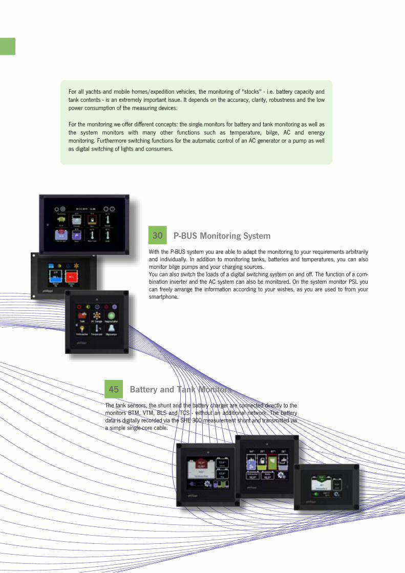
45 Battery and Tank Monitors The tank sensors, the shunt and the battery charger are connected directly to the monitors BTM, VTM, BLS and TCS - without an additional network. The battery data is digitally recorded via the SHE 300 measurement shunt and transmitted via a simple single-core cable.
For all yachts and mobile homes/expedition vehicles, the monitoring of "stocks" - i.e. battery capacity and tank contents - is an extremely important issue. It depends on the accuracy, clarity, robustness and the low power consumption of the measuring devices. For the monitoring we offer different concepts: the single monitors for battery and tank monitoring as well as the system monitors with many other functions such as temperature, bilge, AC and energy monitoring. Furthermore switching functions for the automatic control of an AC generator or a pump as well as digital switching of lights and consumers.
P-BUS Monitoring System With the P-BUS system you are able to adapt the monitoring to your requirements arbitrarily and individually. In addition to monitoring tanks, batteries and temperatures, you can also monitor bilge pumps and your charging sources. You can also switch the loads of a digital switching system on and off. The function of a com-bination inverter and the AC system can also be monitored. On the system monitor PSL you can freely arrange the information according to your wishes, as you are used to from your smartphone.

54
55
50
53
Battery Deep Discharge Protection The battery main switch can be operated by remote control. At the same time, the adjustable undervoltage and overvoltage protection protects the battery from deep discharge.
Navigation Lights Monitor Functioning navigation lights are an essential safety criterion in the dark. The electronic monitor POS6 controls up to six lanterns and reports faults both visually and acoustically.
Bilge Pump Control To monitor the bilge, we have a newly revised bilge pump monitoring panel. It alerts you immediately in case of water ingress. You recognize the operational readiness and can acknowledge the alarm.
Tank Monitoring We offer different tank measuring systems to monitor your tanks. Depending on installation situation, medium and desired accuracy there is a suitable solution.
Supervision

N°
20
30
P - B U S
Tank Interface
CMT 2
B2B Charger
DCE
Battery Management
Shunt SHX/SHC
Digital Switching E-T-A PowerPlex
DC-Battery Main Switch
FBC/TSC
DC Switching Interface
CMR4
k P H I L I P P I P - B U S
n M12-Cable 0,5 m Order-No.: 5 0411 1158
n M12-Cable 1 m Order-No.: 5 0411 1152
n M12-Cable 2 m Order-No.: 5 0411 1153
n M12-Cable 5 m Order-No.: 5 0411 1154
n M12-Cable 10 m Order-No.: 5 0411 1157
The P-BUS is a modern communication network based on CAN bus, that has been adapted to the specific requirements of power supply systems and battery monitoring. Special attention was paid to the energy requirements, since this system, in contrast to navigation systems under NMEA 2000, must be constantly in operation. The architecture as an open system ensures that expansions are possible at any time. This makes the system future-proof for all future expansions, without current components becoming obsolete. Various interfaces and bridges enable communication with other systems.
X-tender Interface
MasterBus Interface
Since 2013, we have been using the waterproof M12 connector system for cabling the individual P-BUS components. This system is known in industry under the name DeviceNet™ and is also used for the NMEA2000® system. This means that the NMEA2000® cables can also be used for the P-BUS, but the P-BUS must never be directly con-nected to the NMEA2000® system, but only via the NMEA2000® Bridge CBN. In order to save valuable energy, all components connected to the P-BUS are put into energy saving mode as soon as all system monitors are in standby or switched off. All delivered P-BUS compatible devices are supplied with a T-adapter cable. Only the connecting cables between the single devices are required.

N°
20
31
NMEA2000®
Bridge
Temperature Interface TPC
AC Interface
CAV
Battery Charger
ACE
EM-Box
Energy-Shunt
SHL 312
k P H I L I P P I S Y S T E M M O N I T O R E
The system monitors PSL, PSM2 and PSS are the central display and control elements of the electrical system on board. They enable the monitoring, control and configuration of all P-BUS compatible components. The clear structure of the System Monitors enables intuitive and logical operation via the touch screen. Several system monitors PSL, PSM2 and PSS can be mounted side by side to display different information like tanks, batteries, current balance or AC grid at the same time. Alternatively, multiple PSL, PSM2 and PSS system monitors can be installed at different locations on board to
independently retrieve the desired information. With the system monitor PSM2 and PSL as the central unit, you can expand your on-board system step by step at any time, from the smallest expansion stage, e.g. with only one shunt SHX as the battery monitor, to the function as a multifunctional display or control panel in a digitally switched CAN bus system. The P-BUS is not a NMEA2000® compatible system and may only be connected to it via a NMEA Bridge CBN!
System Monitor PSS
(only Slave)
System Monitor
PSM2
System Monitor
PSL
TERMINATOR MALE
TERMINATOR FEMALE
M12- T -CONNECTOR M12- 4T -CONNECTOR
M12- T -CABLE
M12- RJ45 T -CABLE
n M12-T-Connector Order-No.: 5 0411 1149
n M12-4T-Connector (quadruble) Order-No.: 5 0411 1145
n M12-RJ45 T-Adapter Order-No.: 5 0411 1148
n M12-T-Kabel 0,2 m (90°angled) Order-No.: 5 0411 1159
n M12-Terminator male Order-No.: 5 0411 1151
n M12-Terminator female Order-No.: 5 0411 1156
n M12-Connector male for assembly Order-No.: 4 0437 1205
n M12-Connector female for assembly Order-No.: 4 0436 1205

N°
20
32
DC-Battery Mainswitch FBC/TSC
Tank Interface
CMT 2
Battery Management
Shunt SHX/SHC
Current (DC) Charge (DC)
Battery switch Digital switchingShore power (AC)
Inverter (AC+DC)
Battery Tank Temperature Bilgen Masterbus
Digital Switching E-T-A PowerPlex
DC-Switching Interface
CMR4
DC Switching Interface
CMR4
Temperatur
Interface TPC
Solar charger
SCE
Interface
Masterbus/Studer
Interface Masterbus
B2B Charger
DCE
AC Interface
CAV
AC Switchover
LAU
Battery
Charger ACE
EM-Box
EM-Box
EM-Box
Energy Shunt SHL
S U P E R V I S I O N
D C E N E R G Y
S W I T C H I N GA C E N E R G Y
k O V E R V I E W P - B U S C O M P O N E N T S

N°
20
33
n Simple registration and configuration of the P-BUS devices without additional computer n Open system, expandability by connecting further components. Future-proof through further development of the software n Capacitive touchscreen with gorilla glass n Brightness sensor adjusts display brightness automatically n Data recording on SD card n Simple intuitive operation due to flat menu structure
P-BUS System Monitor for display, control and monitoring of all data. 5" full colour TFT graphic display with touch screen. An M12-T cable and the two P-BUS terminators (terminating resistors) are included.
Operation Voltage 8 - 32 V DC
Consumption 120 mA, stand-by 4 mA @ 12V
Dimensions W 157,5 x H 105 x D 35 mm
Cut out W 140 x H 85 mm
n PSL Order-No.: 0 7100 2250
The system monitor PSL informs on its 5" color touch screen on 3 different sides about all available data of the electrical system. The information display shows the battery, tank, temperature and bilge information. The energy page informs about the status of the DC and AC system. On the control page the main switches and the consumers can
be switched. If you have more than eight information symbols, the display can be moved virtually to the left or right by simply moving it. On the info and switch screen pages, you can arrange the displayed elements yourself, just as you are used to arrange your smartphone apps.
The energy page shows the energy flow very clearly. The energy flow is shown between the DC direct current network (battery) and the AC alternating current network. The interface between the AC and DC grid is a combination inverter that connects both grids. The data of the combi inverter is read in via a Studer or Masterbus interface.
The switching functions are shown on the switching side. Both the battery main switch can be operated and the switching status of the automatic functions of the CMR4 universal relay module can be read and also manually controlled. Furthermore, switching functions for switching and dimming LED lights and other consumers are also available, also in connection/as control unit for the ETA Powerplex system.
Basically, all elements from which information is obtained via the P-BUS are displayed. No special configuration software is required - the system configu-res itself almost automatically. After installation, the connected P-BUS devices must be registered once, nothing more has to be done. The PSL system monitor can be installed both vertically and horizontally.
P S L M O N I T O R
k P H I L I P P I S Y S T E M M O N I T O R P S L

N°
20
34
The system monitor PSS serves as a daughter display to a PSM2 or PSL monitor. It is equipped with a 2.4" colour touch screen and displays the available battery, tank, temperature and energy data on 4 pages. It can only be operated in parallel with an operating PSM2 or PSL. No settings on the monitor are necessary for operation as all system settings are taken over from the main monitor PSM2 or PSL. The configuration of the connected components is also done on the main monitor PSM2 or PSL.
P-BUS System Monitor PSS for displaying and operating single menues. 2,4“ full coloured TFT touch screen graphic display. A M12-T-cable is part of delivery.
Operation voltage 8 - 32 V DC
Comsumption 70 mA, Stand-by: 4 mA
Dimensions W 105 x H 75 x D 35 mm
Cut out W 87 x H 65 mm
n PSS Order-No.: 0 7100 2224
k P H I L I P P I S Y S T E M M O N I T O R P S S
P S S M O N I T O R
BATTERY MONITOR Apart from the current, voltage and capacity display the battery level is shown graphically. Further information as remaining time and statistics are available on command.
TANK MONITOR Different kind of liquids are shown in different colours independently from the tank sensor. If the tank level exceeds or falls below a given threshold the respective tank will be displayed in red.
TEMPERATURE MONITOR Temperature monitoring of engine com-partment, cargo compartments, interior and exterior temperature with alarm function, Min. and max. temperature with time stamp is possible with the temperature interface TPC and two different sensor types.
ENERGY MONITOR DC
The ongoing charge or discharge currents of the sources and loads are displayed in an energy scheme. Alternatively the energy up to now charged or used can be shown (e.g. the harvest of a solar panel per season).
DAY, NIGHT AND POWER SAVING MODE You can switch directly between day and night mode by pressing the relating key. A long press on the button puts the PSS into standby mode, where power consumption drops to 6 mA to save precious energy. Each touch of the touch screen restarts the PSS.
TPCSHX/SHC, EM-box CMT 2 SHL, ACE, EM-box

N°
20
35
P-BUS System Monitor for displaying and operating the P-BUS. Intuitive coloured TFT touch screen graphic display, with adjustable brightness. A M12-T-cable and both P-BUS Terminator resistors are part of delivery.
Operation voltage 8-60 V
Consumption 100 mA, Stand-by: 6 mA
Dimensions L 105 x W 105 x H 35 mm
Cut out 88 x 88 mm
n PSM 2 Order-No.: 0 7100 2235
k P H I L I P P I S Y S T E M M O N I T O R P S M
BATTERY MONITOR
Apart from the current, voltage and capacity display the battery level is shown graphically. Further information as remaining time and statistics are available on command.
TANK MONITOR
Different kind of liquids are shown in different colours independently from the tank sensor. If the tank level exceeds or falls below a given threshold the respective tank will be displayed in red.
ENERGY MONITOR DC
The ongoing charge or discharge currents of the sources and loads are displayed in an energy scheme. Alternatively the energy up to now charged or used can be shown (e.g. the harvest of a solar panel per season).
ENERGY MONITOR AC
The performance data and operating states of combination inverters (Studer X-tender / Mastervolt) are clearly displayed and the most important settings can be adapted.
The 3.5" colour touch screen informs you on different pages about all available data of your electrical system. The main menu shows the menu items for which data is available from the connected devices. Log When the SD card is inserted, all data from the batteries and energy sources can be recorded and later analysed on a PC. Even when the PSM2 is in stand-by mode, the data is recorded every minute. The data in CSV format can be displayed at any time in a spreadsheet for analysis. Alarm messages Messages from empty batteries, in case of overvoltage, after an undervoltage switch-off or from full/empty tanks are listed in an alarm list. As soon as a new alarm arrives, the list is displayed again and an acoustic alarm can be activated on request.
P S M M O N I T O R
TEMPERATURE MONITOR Temperature monitoring of engine com-partment, cargo compartments, interior and exterior temperature with alarm function, Min. and max. temperature with time stamp is possible with the temperature interface TPC and two different sensor types.
BILGE MONITOR The activity of one or more bilge pumps is logged and displayed via the CMR 4 switch interface. The automatic or manual function is optionally active. On the System Monitor you can see the active mode by its color.
DIGITAL SWITCHUING
The switching of loads in a digital bus system enables convenient operation from one or more locations. In con-junction with LED lamps and the CMR4 interface, a trouble-free dimming function of the LED luminaires is available.
MAIN SWITCH MONITOR
The battery main switches can be switched by keypress. An optional PIN code protects the system against unauthorised use. The deep discharge protection of the batteries can be activated on demand.
CMR4
SHL, ACE, EM-box
FBC, TSC, EM-box CMR4 TPC
SHX/SHC, EM-box CMT 2 LAU, CAV, Studer, Mastervolt

N°
20
36
SHX/SHC SHX/SHC
B A T T E R Y M O N I T O R I N G
BATTERY CAPACITY The bar height of the battery indicates how much remaining capacity is available. The light blue area shows the usable capacity up to the set capacity alarm. The dark blue area shows the theoretically available capacity until the battery is completely discharged (deep discharge), which should always be avoided in order not to damage the battery. If the shunt SHX has detected during operation that the nominal battery capacity is not available, e.g. due to ageing influences, by reaching a deep discharge prematurely, this unusable part of the total capacity is represented by a dark grey area. By touching the battery symbol you can switch between the remaining capacity in Ah, the remaining time until the capacity alarm and the battery temperature (temperature sensor Temp-BT required).
The battery management shunt SHX precisely records the current, voltage and capacity of the connected battery. The galvanically isolated P-BUS enables the acquisition of battery data from battery groups isolated from the vehicle electrical system (e.g. emergency battery for radio systems or
electric drives). The active shunt SHX calculates the current battery capacity from the continuously measured current and voltage values and the System Monitor displays this in colour in the battery symbol.
Battery Alarms In the event of overvoltage, or when the voltage falls below the set warning threshold or when the battery is recognised as almost empty or deeply discharged, a warning message appears on the display. Battery analysis At each battery cycle, the collected data is analyzed. The CEF (charge efficiency) and the number of cycles at which the set minimum cycle depth has been reached can be queried. The number of deep discharges and the average discharge depth are also recorded. This allows conclusions to be drawn about battery usage and wear. Recording the battery temperature The battery temperature can also be monitored via the optional temperature sensor.
k P - B U S B A T T E R Y M A N A G E M E N T S H U N T S H X
Measurement of a 2nd battery voltage In addition to the house battery, the voltage of a starter battery can also be recorded. The second battery voltage is displayed on the System Monitor in a separate monochrome battery symbol. If the voltage of this battery falls below a set alarm threshold, the battery is displayed in red and an alarm message is output.
Monitoring One 24V battery To monitor a 24V battery block, it is recommended to measure the partial voltage to be aware of uneven charging and the resulting premature failure of the batteries.

N°
20
37
Temperature sensor for battery-management-shunt
n Temp-BT Order-No.: 0 5900 3000
Digital battery management shunt for installation in
the negative line between battery and neg. termi-
nal. Power supply via the positive measuring line.
Connection bolts M8.
Current rating 300 A, 600 A 1 min,
1500 A 0,5 s
Consumption 20 mA (5 mA sleep-mode)
Operating voltage 8 -32 V
Current range 10 mA - 300 A
Dimensions L 118 x W 40 x H 65 mm
Digital battery management shunt for higher
currents / bigger loads. Connection bolts M16.
Matching negative bus bar SAS 4
Current rating 600 A, 800 A 1 min,
2500 A 0,5 s
Consumption 6 mA@12 V, 4 mA@24 V
Operating voltage 8 -60 V
Current range 10 mA - 600 A
Dimensions L 185 x W 44 x H 75 mm
n SHX 300 Order-No.: 0 7100 0305 n SHC 612 Order-No.: 0 7100 0612
This bus bar will be attached directly on the shunt
SHC 612 to connect smaller lugs / lines
(M12, 2x M10, M8).
Dimensions L 140 x W 30 x H 30 mm
n SAS 4 Order-No.: 0 8000 9014
k S Y S T E M M O N I T O R B A T T E R Y & T E M P E R A T U R E M O N I T O R I N G
Interface for 4 temperature sensors
Connection via pluggable screw terminals.
A M12-T-cable is included in delivery.
Operation voltage DC 8 -32 V
Consumption 8 mA
Dimensions (mm) L 107 x W 85 x H 40
n TPC 4 Order-No.: 0 7100 0104
k P - B U S T E M P E R A T U R E I N T E R F A C E T P C
With the temperature interface TPC 4 important temperature values can be recorded. Per temperature interface 4 temperature sensors Temp-HT or Temp-BT can be connected. Up to four TPC 4 can be connected to the P-BUS.
Individual limit values can be set for each temperature sensor, which generate an alarm as soon as the limit values fall below or exceed. Temperature-dependent actions can be switched via the CMR4 relay module.
T E M P E R A T U R E M O N I T O R I N G
Temperature sensor for temperature interface TPC
4. NTC sensor integrated in plastic housing cast,
with PVC cable 2.8 m.
Can be used for measurement of water and air
temperatures from -30°C to +70°C.
n Temp-BT Order-No.: 0 5900 3000
Temperature sensor for temperature interface TPC
4. NTC sensor inserted in brass cable lug encap-
sulated and electrically insulated.
Hole Ø 4 mm Cable length 32 cm.
Can be used to measure temperatures from
+30°C to +250°C.
n Temp-HT Order-No.: 0 5900 3300
The following temperature values are of interest on board yachts and in vehicles: Air temperatures (inside / outside / battery room / engine room / storage / refrigerator / freezer compartment)
Water temperatures Engine cooling water sweet + salt / Exhaust collector / Sea water / Water tank / Boiler Further temperatures alternator / gearbox / exhaust / cylinder head / turbocharger / engine block / engine oil

N°
20
38
k P - B U S T A N K M O N I T O R I N G
Interface for the P-BUS for the integration / measurement of up to 4 different tank
sensors. Connection by plug-in screw terminals. Connection to the P-BUS via a M12-
terminal. A M12-T-cable is part of delivery.
Operation voltage DC 8-32 V
Consumption Stand by : 7,5 mA @ 13 V
Active : 10 mA @ 13 V
Dimensions L 107 x W 85 x H 40 mm
The CMT2 interface is required to integrate tanks or tank sensors in the P-BUS network. It provides the independent measurement of up to 4 different tank sensors and makes this information available to the
P-BUS. The parameters such as sensor type, tank size, tank characteristic, alarm level, ...) are set via the System Monitors PSM2 / PSL.
MANY TANK SENSORS CONNECTABLE You can connect different tank sensors (also mixed) to the tank interface CMT 2: matching tank sensors please see page 50: l Tank sensor 10–180 Ohm (Series TGW / TGT) l Tank sensor 240–33 Ohm l Tank sensor 0–300 Ohm (free adjustment) l Tank sensor 4–20 mA (Pressure sensor TDS) l Ultrasonic-tank sensor 0,5–2,5 V (UTV) l Ultrasonic-tank sensor: free adjustment of tank depth (UTV 40/80) l Tank sensor 0–5V (0–10V with hardware modification) l Flow sensors DFS l Tank sensor 0–1 (Switch sensors TRS 130 / RSW)
DISPLAY OF % OR LITRES (GALLONS FOR USA) By touching a tank symbol the display of the PSM switches between percent, no unit and litres / gallons. Flow sensor DFS: after having filled up the tank the volume can be adjus-ted by pressing the relating tank symbol for a while. CONFIGURATION OF THE DISPLAY For each connected tank sensor there is an individual menu in the setup of the PSM for the following adjustments: i.e. name, place, type of sen-sor, compensation, tank volume, alarm threshold, alarm duration. COMPENSATION OF THE TANK GEOMETRY If your tank isn`t rectangular, there is a correction / compensation opportunity in order to get the most exact display for each display. If the tank is designed very unusual, the values for 0, 25, 50, 75 and 100% can be set in the menu in order to get the optimum display of the measured tank volume. INTEGRATION OF A WATER MAKER By using 2 Flow Sensors DFS the water level can be calculated by measuring both water consumption and water production (water maker). The sum will be displayed on the relating tank symbol on the PSM.
n CMT 2 Order-No.: 0 7100 0401
T A N K M O N I T O R I N G
Overv iew o f our tank measur ing sys tems
PRESSURE PROBE The tank probes TDS/TDN are suspended as immersion probes to the bottom of a tank. - high resolution, no moving parts - up to tank heights of 2 m - TDS for diesel, water, grey & waste water - TDN for water, grey & waste water - TDT for diesel, water, grey & waste water
TANK SENSOR The universal tank sensor for everything except black water! - Resolution 16 mm, very robust and durable - TGT for diesel & gasoline, grey water - TGW for fresh water - can be unscrewed and screwed in, thus easy to maintain.
ULTRASONIC SENSOR The non-contact level control measurement for waste water and holding tanks. Level measurement only pos-sible in horizontal position. Unsuitable for fuel and water tanks.
FLOW SENSOR The flow sensor is liter accurate and only suitable for fresh water! After refuelling, the filling level must be manually set to "full" again.

N°
20
39
k P - B U S R E M O T E B A T T E R Y M A I N S W I T C H
B A T T E R Y M A I N S W I T C H
Remote battery main switch with adjustable deep discharge and overvoltage
protection. Operation via an external push button and/or P-BUS. All adjustments
can be set in the PSM/PSL. Manual emergency operation directly at the
relay possible. A M12-T-cable is part of delivery.
Rated voltage 12 + 24 V DC
Rated current 260 A
Consumption 2 mA
Dimensions L 124 x W 95 x H 50 mm
Bipolar version of the remote battery main switch FBC. Manual emergency
operation directly at the relay possible. A M12-T-cable is part of delivery.
Rated voltage 12 + 24 V DC
Rated current 2x 260 A
n FBC 265 Order-No.: 0 8302 2750
n FBC 265 Bipolar Order-No.: 0 8302 2755
FBR 500
Details page 71
Interface for the operation of an external battery main switch 500A
FBR 500-12 or FBR 500-24 with adjustable deep discharge and overvoltage
protection. Operation via an external push button and/or P-BUS.
All adjustments can be set in the System Monitor. A M12-T-cable is part of
delivery. The relay FBR 500-12 / 24 has to be ordered separately!
Rated voltage 12 + 24 V DC
Consumption 2 mA
Dimensions L 111 x W 90 x H 41 mm
n TSC Order-No.: 0 8302 0000
PIN-PROTECTED OPERATION To prevent unauthorized operation of the main switches, the operation can be protected by a PIN. This is done by a small key appears in the button. Each main switch can be assigned a name for unique identification. ADJUSTABLE DEEP DISCHARGE PROTECTION If the connected battery is to be protected against deep discharge or overvoltage, this can be activated via the system monitor. The voltage thresholds and delay times can be set individually. BATTERY VOLTAGE DISPLAY If the battery voltage is to be displayed at the main switch input in the battery view, this can be activated via the System Monitor. This eliminates the need to lay an additional voltage measuring cable.
For convenient switching of the battery main switch or the power supply. The FBC 265 remote-controlled main battery switch is used for the control of high-current loads such as winches, anchor winches and inverters (ener-gy management). The adjustable over- and undervoltage protection also protects the battery from deep discharge. If the continuous current load is greater than 260 A (e.g. bow thruster), the
current carrying capacity can be increased to 500 A by combining the TSC interface with the remote main switch FBR 500. For independent operation of the main switch from the P-BUS, we recommend installing a control button also for emergency operation. The battery main switch can be manually operated directly on the relay via the red and yellow buttons.

N°
20
40
k P - B U S S W I T C H I N G I N T E R F A C E C M R 4
FURTHER SWITCHING AND MONITORING FUNCTIONS OF THE CMR4 RELAY MODULE
ENERGY MANAGEMENT For switching off consumers with adjustable remaining battery capacity, e.g. for automatic deactivation of inverters. The switching information is supplied by a battery management shunt SHX. Mono- or bistable high current relays can be operated CONTROL OF AN AC GENERATOR For controlling an AC generator with automatic start or start/stop buttons. The information for switching the generator on and off is provided by the Battery Management Shunts SHX (Generator ON/OFF setting). One shunt or several shunts can provide the start/stop signal. A control signal can be connected and an operating time can also be stored to block generator operation, e.g. when a shore connection is active.
VISUALIZATION OF ALARM MESSAGES Alarm messages can also be displayed via external buzzers or indicators if the System Monitor is mounted elsewhere. PUMP OPERATION By means of adjustable switch-on and switch-off thresholds, a pump can be switched on (automatic refilling of a day tank) or deactivated (toilet pump with full tank) for a defined time. TEMPERATURE DE-ACTIVATION Adjustable switch-on and switch-off thresholds can be used, for example, to switch off battery charging for a defined period of time in order to prevent overcharging of the battery system at high temperatures.
Monitoring the bilge pump function is one of the many functions of the CMR 4 switching interface. The activity of one or more bilge pumps is logged and displayed on the System Monitors. The relay module CMR 4 has to be installed between float switch and bilge pump.
Depending on the setting, the CMR 4 only logs the function of the bilge pump or reports the alarm of the bilge sensor, the bilge pump must then be activated manually via the monitor.
The operating time in minutes of the current day is displayed above the bilge symbol. Below the bilge symbol, the number of power-ups in the current hour and the number of power-ups in the current day. These counters are set to 0 when a new day or hour starts. The symbol also serves as a button. A long pressure of approx. 2 seconds switches the bilge pump on or off. A short touch opens a page with a statistical evaluation of the use of the bilge pump. The monthly average values of the switch-on procedures and the operating times are also displayed here. With the "Reset" button, all displayed values can be set to 0 after successful entry of the system PIN.
The status of the bilge pump is displayed on the System Monitor as follows: Bilge white: Bilge pump is switched off, no alarm Bilge flashing red: Bilge pump is switched off, an alarm is triggered. Bilge green: Bilge pump in operation
C O N T R O L A N D M O N I T O R I N G

N°
20
41
Switching interface incl. 4 monostable relays (10 A nominal rating). Integrated
time base for the system clock.
4 potential free relay outputs with fuseholder for a fuse / circuit breaker
4 operation inputs for direct switching at the interface
4 PWM-outputs for the dimming function (open-collector and 8V voltage signal )
Connection by screw terminals. M12-T-cable included in delivery..
Operation voltage DC 8-30 V
Consumption Stand by all relays off: 9 mA @ 13 V
Active all relays off: 13 mA @ 13 V
Active all relays on: 85 mA @ 13 V
Current rating / relay: 10 A
Dimensions L 115 x W 105 x H 50 mm
k P - B U S S W I T C H I N G I N T E R F A C E C M R 4
nCMR 4 Order-No.: 0 7100 0044
SWITCHING CONSUMERS WITH DIMMING FUNCTION Consumers can be switched on and off via the PSM system monitor. A large selection of graphic symbols is available for selection, which can also be extra labeled. Switching commands can also be sent and feedback messages received for the E-T-A Powerplex System. SWITCHING WITH FEEDBACK The consumer is switched ON or OFF by pressing the buttons. The switched-on consumer is indicated by a green checkmark. A defective fuse at the output is reported to the system monitor and indicated by a red "flash" symbol.
Interaction with the E-T-A Powerplex System. Switching commands can be sent and feedback messages received. Various interfaces are available. Applicable for 12/24V.
8 outputs, each 1,5 A, dimmable 8 inputs digital / analog max. 12 A 32 mA
Outputs Inputs Total Power Standby consumption
8 outputs, each 8 A, dimmable 10 inputs digital 3 inputs analog 0...10 V max. 60 A / 12V! 5 mA
4 outputs, each 1 A 6 outputs, each 8 A, dimmable 2 outputs each 25 A 8x digital, 4x analog 0...10 V max. 102 A 85 mA
DIMMING FUNCTION FOR LED LIGHTS If the button is pressed for a long time, a new screen window appears in which the brightness of the luminaire can be adjusted, provided that a dimmable LED luminaire with corresponding control input e.g. LED lights from Prebit (slave version) has been connected.
E-T-A Powerplex Mini-Modul MM300
E-T-A Powerplex Compact-Modul COM24
E-T-A Powerplex Marine-Modul DC024
D I G I T A L S W I T C H I N G

N°
20
42
Battery Negative
Solar cells
Alter- nator
Loads
k P - B U S D C E N E R G Y M E A S U R E M E N T
DC ENERGY BALANCE The DC energy monitor of the system monitor shows the energy balance of the DC system. Depending on the configuration with individual SHL current measurement shunts or an EM-box (8 shunts), the current flows can be analyzed in detail. The charging sources are shown in the upper part, the loads (consumers) and the battery system in the lower part. This makes it easy to see which charging sources feed energy into the DC system and which loads (consumers) consume the energy.
RECORDING OF THE ENERGY PRODUCTION For example, would you like to know the weekly yield of your solar cells or other regenerative energy sources? By tapping on the energy screen, you can switch to the display of the amp hours delivered or consumed since the last counter reset.
In addition to displaying the current battery status, it is often very interesting to know which energy sources such as solar cells, wind generators, alternators or hydrogen generators supply how much charging current and which consumers consume it, since the current display of the batteries via the SHX shunt only shows the difference between charging and discharging current.
Digital current measuring shunt for installation in the negative line of a charging
source or consumer. The power supply is connected via the pluggable terminal.
Connection bolts M8, P-BUS connector M12-T.
Strombelastbarkeit 300 A, 600 A 1 min, 1500 A 0,5 s
Stromaufnahme 20 mA (5 mA sleep-mode)
Betriebsspannung 8 -32 V
Meßbereich 10 mA - 300 A
Abmessungen L 118 x B 40 x H 65 mm
n SHL 300 Order-No.: 0 7100 0306
With its 10 integrated shunts, the EM-box pro-vides a comprehensive overview of the DC system. The screen shows the standard configuration when all channels are occupied.
If an ACE series charger is connected via a P-BUS interface, the detailed information of the device is available and the most important device functions such as silent mode/power limitation can be selected directly.
Battery Charger ACE EM-Box
D C E N E R G Y

N°
20
43
P-BUS AC-Interface for DIN rail assembly for measuring of a single AC phase
230V / 50Hz. The connection by screw terminals. Connection to the P-BUS via a
M12 T-cable, which is part of delivery.
Current range 16 A (int. shunt)
100 A (via external converter WAC)
Dimensions L 76 x W 53 x H 46 mm
Current transformer max. 100 A sui-
table for AC-Interface CAV
Dimensions
L 35 x W 35 x T 15 mm
MASTERBUS
AC SOURCE SELECTOR SWITCH LAUSTUDER
n CAV Order-No.: 0 7100 0230
n WAC 100 Order-No.: 0 7100 4626
The AC interface CAV records the current and voltage of 230V AC devices and makes the information available to the P-BUS: n AC Onboard Voltage [V] n AC Onboard Current [A] n Used kilowatt-hours kWh since last reset n Name of the source / consumer for unambiguous identification
To visualize the energy flow of the electrical AC system, various devices are often available that are already capable of supplying data. These have to be collected and displayed. The following devices already provide P-BUS-capable AC data: n Battery chargers series ACE n Shore Power Switching Units LAU The following devices can supply P-BUS-enabled data via an interface: n Studer X-Tender Combi-Inverter/Chargers and VT Solar Chargers n Mastervolt Combi-Inverter/Chargers For power sources and consumers without P-BUS connection, an AC interface CAV is installed and set accordingly.
In combination with an AC switching unit LAU (page 76), the existing AC current sources, their current voltage and the active source are also displayed.
k P - B U S A C E N E R G Y M O N I T O R I N G
> Xcom CAN Order-No.: 7 0006 9042
The Xcom CAN Bridge is required to display the data of the Xtender combi inverter/chargers and to make the configuration settings from the system monitor. Power is supplied via the Xtender network.
Dimensions L 113 x W 76 x H 25 mm
The Masterbus Bridge provides the data from many Mastervolt devices like: > MASS Combi (Ultra) > CombiMaster > MLI Lithium Batteries > SCM Solar Chargers > MAC plus DC/DC converter > ChargeMaster > MasterShunt For more information please find page 44.
A C E N E R G Y

NMEA2000®P-BUS SuperBP-BUS
N°
20
44
k P - B U S I N T E R F A C E
In order to output the battery, tank and other P-BUS data of the System Monitor to chartplotters and NMEA2000® compatible devices, an NMEA 2000® Bridge is required to convert the data accordingly. The following PGNs are currently supported: 127501, 127505, 127506, 127508, 127744, 127747, 127750. Please check which PGNs can currently be displayed by your plotter, as this depends on the manufacturer and soft-ware version.
This interface allows access to the data of voltage, actual charge/dischar-ge current and state of charge of the SuperB Nomia and Nomada lithium batteries via the P-BUS to display the data on the system monitors PSL and PSM 2. This provides the voltages of individual cells and other important data for battery analysis.
To integrate Mastervolt devices into the P-Bus, the interface CMB is used. This allows Mastervolt data to be displayed on the PSL and PSM 2 system monitors and some settings to be made that are required in daily operation. All Mastervolt devices can be obtained from us.
The following Mastervolt devices are supported by the CBN: > MASS Combi Ultra > CombiMaster > MLI Lithium Batterien > Solar Chargemaster > MAC Plus > ChargeMaster > ChargeMaster Plus > MasterShunt
Display of the Combi-Master (Ultra) data on the system monitor PSM 2 The most important set-tings of the Combi-Master (Ultra) can be chan-ged by pressing the blue area.
I N T E R F A C E
> CBN Order-No.: 0 7100 0020
P-BUS - NMEA2000® interface for connection to the P-Bus via the supplied M12-T cable. An additional M12-T cable for connection to the NMEA2000® network is included in the scope of delivery. The CBN is powered via the NMEA2000® net-work.
Dimensions L 107 x W 85 x H 40 mm
> CBO-SB Order-No.: 0 7100 0020
P-BUS - CANopen® interface for connection to the P-Bus via supplied M12 T cable. An additional M12-T cable for connection to the CANopen® network is included in the scope of delivery. The CBO-SB is powered via the CANopen® net-work. The interface eliminates the need to install a shunt.
Dimensions L 107 x W 85 x H 40 mm
The Masterbus Bridge provides data from many Mastervolt devices. The interface is powered via the Masterbus net-work. Delivery includes M12 T-adaptor Dimensions H 66 x W 78 x D 32 mm
> CMB Order-No.: 0 7100 0030

N°
20
45
House batteryNegative
busbar
Starter
battery 1Starter
battery 2
Charger ACE Interface ACE-LIN
Upgrade the BTM monitor to a fully-fledged battery charge management system by connecting an ACE Series charger.
n ACE-LIN Order-No.: 0 8000 4975
The ACE-LIN interface enables ACE chargers to communicate with BTM and BLS monitors. The interface is put into operation by clipping it into the prepared holder in the ACE charger and plugging in the connecting cable. The ACE-LIN interface is only required for the ACE 12/25, ACE 12/40 and ACE 24/20 models. All other models already have an interface.
Type Dimensions Screen size Battery capacity Voltage measurement starter 1 Voltage measurement starter 2 Tank measurement Communication with charger
BTM 105 x 105 mm 3,5“ via SHE 300 via SHE 300 at monitor up to 4 tanks yes, via ACE-LIN
VTM 105 x 105 mm 3,5“ - at monitor at monitor up to 4 tanks
BLS 105 x 75 mm 2,4“ via SHE 300 via SHE 300 at monitor - yes, via ACE-LIN
TCS 105 x 75 mm 2,4“ - at monitor at monitor up to 3 tanks
The battery and tank monitors of the BTM / VTM and BLS / TCS series are designed for direct connection of the sensors on the back of the monitor. This enables a simple, cost-effective and fast installation! The BTM and BLS monitors also serve as remote monitors for the ACE 12-25, ACE 12-40 and ACE 24-20 chargers. Communication between monitor, shunt and charger is via a single wire cable using LIN bus technology. l Clear and concise presentation of all important data on one page l Large and easy to interpret symbols make it easy to read even from
a distance
l Intuitive and simple operation l Apart from the battery measuring shunt, which is installed directly
at the battery, no additional components are required. l Only one single-core connecting cable between monitor and shunt
or between monitor and charger l Colour touch screen l The monitor can be updated at any time via SD card l The number of connected tanks is adjustable l The tank characteristic can be individually adapted - important for
non-linear tanks l Tank sensors from other manufacturers with an output signal of
10-180Ω / 240-33Ω / 0-3 V (TCS) or 0-10 V (BTM/VTM) / 4 - 20 mA can also be connected.
k O V E R V I E W D I G I T A L B A T T E R Y A N D T A N K M O N I T O R S
The electrical connection for battery capacity measurement The battery monitor BTM/BLS is connected to the active shunt SHE via a single-core cable (LIN-bus).
The active shunt SHE has to be installed between the negative line(s) of the service battery(s) and the negative busbar so that there are no further connections to the negative poles of the house battery(s). All other connections to other battery groups, loads and charging devices must be connected to the load side of the SHE shunt. This ensures that all currents are detected and that the battery monitor can operate properly.

N°
20
46
k T H E G A U G E F O R Y O U R B A T T E R Y P L A N T - B L S
Shunt SHE 300Charger ACE
Battery Monitor BLS for displaying a 12/24V house and a 12/24V starter battery. 2.4" TFT colour touch screen graphic display with brightness sensor. The shunt SHE 300 and the interface ACE-LIN are included in the scope of delivery of the BLS-Set Plus!
n BLS-Set Plus Order-No.: 0 7100 3220
Easy Installation The connection between monitor and shunt consists of a single line, even an existing line can be used. Easy Commissioning Just enter the battery capacity of the house battery and the system is ready to use. Easy to use Since all relevant information is summarized on one page, no key has to be pressed. The important information is presented in an understandable way via graphics and enables quick reading.
The ACE-LIN interface integrated into the automatic charger enables the BLS battery monitor to monitor and control the charging process of the ACE automatic charger to optimise charging. The display also shows the AC mains voltage, the active charging phase, the battery temperature, the charging voltage and the charging current. The charging power can be reduced or the silent mode (fan off) activated at the touch of a button. A temperature alarm, for example, can be defined for further charge monitoring.
Battery Monitor BLS for monitoring a 12/24V house and a 12/24V starter battery. 2.4" TFT colour touch screen graphic display with brightness sensor. The shunt SHE 300 is included in the scope of delivery of the BLS!
Technical Data
Rated Voltage 12 V
Consumption max. 50 mA @ 12V, Stand-by: 6 mA
Dimensions W 105 x H 75 x D 28 mm
Cut-out 87 x 65 mm
Current rating 300 A, 600 A 1 min, 1500 A 0,5 s
Expand the BLS monitor by connecting an ACE series charger to create a fully-fledged
Battery charge management system!
Shunt SHE 300
The Battery Monitor BLS is a compact battery monitor for battery systems consisting of a 12/24 V starter battery and one or more 12/24 V house batteries connected in parallel. The 2.4" TFT touch screen displays all important data of the entire battery system at a glance without the need to press a button. The built-in brightness sensor automatically dims the screen at night, saving valuable energy. l Display of the current voltage, the current charge or discharge current, the remaining time, the battery temperature and the state of charge of the consumer battery(s). l Further information on the use of the consumer battery(s): No. of charge cycles, deep discharges & mean depth of discharge. l Warning of a dangerous deep discharge by an adjustable acoustic alarm. l Suitable for all battery types like acid, GEL, AGM and LiFePO4
n BLS-Set Order-No.: 0 7100 3210

N°
20
47
k T H E G A U G E F O R Y O U R B A T T E R Y P L A N T - B T M
Battery Monitoring Precise battery information on the current voltage, charge or discharge current, remaining time, temperature and state of charge of the house battery. Statistical values for the number of charge cycles, deep discharges and average discharge depth give you an overview of the use of the battery. It is possible to monitor the voltage of up to 2 starter battery banks. For further monitoring, individual alarms such as a battery reserve threshold can be defined. Tank Monitoring All known philippi tank sensors such as TGT/TGW, UTV, TDS/TDN/TDT and DFS can be connected, even existing tank sensors from other manufacturers with the signals 10-180Ω /240-33Ω / 0-5 V/ 0-10 V/ 4-20 mA are possible. Each tank can be individually configured for unambiguous assignment, and adaptation to non-linear tank geometries is also possible. For monitoring purposes, individual minimum or maximum alarm thresholds can be defined for each tank. Charge Monitoring An ACE-LIN interface integrated in the ACE automatic charger enables monitoring of the charging process, the display of the mains voltage, the charging phase, the battery tempera-ture and the charging current. Adjustment of power and silent mode (fan off). Alarm output An adjustable alarm warns in time of a dangerous deep discharge of your batteries, empty tanks or batteries that are too hot. In addition to the text display, the alarm message can also activate the internal buzzer as well as the integrated potential-free relay. Easy Installation The connection between monitor and shunt consists of a single line, even an existing line can be used. All tank sensors are connected on the back of the monitor.
Digital battery management shunt for installation in the negative line of the house battery. The SHE 300 shunt is compatible with the BTM and BLS monitors. The shunt is powered via the consumer battery's voltage measuring line. Suitable for continuous charging or discharging currents up to 300 A and battery capacities up to 1000 Ah
Rated current 300 A, 600 A 1 min, 1500 A 0,5 s
Consumption 10 mA@12 V, 5 mA@24 V
Operation voltage DC 8 -40 V
Current range 10 mA - 1500 A
Connection Bolts M8
Dimensions L 118 x W 40 x H 65 mm
The combined digital battery and tank monitor BTM is the successor of the well-known and successful battery monitor series BCM and the tank monitor series TCM. It`s 3.5-inch color touch-screen graphic display provides an overview of the battery system status and the level of up to four tanks and shows the
status of the ACE charger during operation. It allows the connection of a battery shunt SHE 300 for battery monitoring, the direct connection of 4 tank sensors and the connection of an automatic charger ACE via the interface ACE-LIN. Suitable for all battery types such as acid, GEL, AGM and LiFePO4.
Battery, tank and charge monitor BTM. Intuitive, 3.5" colour TFT touchscreen graphic display with brightness sensor for automatic adjustment of display brightness. The tank sensors, the shunt "SHE 300" and the interface to the charger "ACE-LIN" must be ordered separately.
Operation voltage 8-32 V
Consumption max. 70 mA @ 12V, Stand-by: 6 mA
Dimensions L 105 x W 105 x H 35 mm
Cut-out 88 x 88 mm
One monitor and many possibilities. Whether as a battery monitor, as a tank monitor or just as a charge monitor, anything is possible.
Everything at once also works!
n BTM Order-No.: 0 7100 4000
n SHE 300 Order-No.: 0 7003 0300

N°
20
48
Overv iew o f our tank measur ing sys tems
SIMPLE COMMISIONING VIA GRAPHICAL USER MENU The settings are stored when the supply voltage fails and are available again when switched on again.
k D I G I T A L T A N K M O N I T O R
CONFIGURATION OF THE DISPLAY For each connected tank sensor, the volume, tank type and sensor type can be entered in the setup and adapted to the tank geometry. DISPLAY OF LITRES OR % The tank volumes of the individual tanks can be stored in the setup, so that the filling levels can be displayed converted into litres. Alternatively, the % value or only the level bar can be displayed. It should always be noted that the litre display cannot be accurate to the litre (except for flow sensors) due to the limited resolution of the tank sensors! POWER SAVE MODE The tank sensors are queried by an interval measurement in order to reduce the current consumption of the system. If the supply voltage drops below 11.5 V / 23 V, the power save mode is activated and the polling frequency is reduced in order to further reduce the current consumption. BATTERY AND TANK MONITORING The alarm function that can be activated for each tank individually monitors the tank levels and gives an acknowledgeable acoustic alarm (duration 1 min.) if the set limit value is exceeded or not reached. If the battery voltage is lower or higher than the adjustable alarm thresholds, this is signalled by an acoustic alarm (1 min.) and flashing voltage value.
ADAPTATION TO NON-RECTANGULAR TANK GEOMETRIES For non-rectangular tanks, the level indication can be freely entered via five level values 0, 25, 50, 75 and 100% in order to optimally adjust the level indication. Alternatively, these values can also be accepted by the tank sensor at the push of a button during the initial calibration. During the adjustment, the current measured value of the sensor can be read off.
The new generation of tank monitors enables compact tank monitoring for yachts and vehicles with up to 3 (TCS) or 4 (VTM) tanks. Two battery groups the voltages can be monitored in parallel. The full colour TFT touch screen shows all tank levels and battery voltages at a glance, without the need to operate a button. The built-in brightness sensor automatically dims the screen in the dark and saves valuable energy.
All known philippi tank sensors such as TGT/TGW, UTV, TDS/TDN/TDT can be connected, even existing tank sensors from other manufacturers with the signals 10-180Ω / 240-180Ω / 0-3 (10) V / 4-20 mA are possible. For battery and tank monitoring, individual minimum or maximum alarm thresholds can be defined for each battery and tank.
PRESSURE PROBE The tank probes TDS/TDN are suspended as immersion probes to the bottom of a tank. The probe measures the current level in the tank via the hydrostatic pressure of the liquid. - high resolution, no moving parts pieces - up to tank heights of 2 m - TDS for diesel, water, waste water - TDN for water, waste water
FLOAT SENSOR The universal tank sensor for every-thing except black water! - Resolution 16mm, - Very robust and durable - Output signal compatible with the most fuel gauges - TGT for diesel & petrol, grey water - TGW for fresh water - Unscrewable and screwable, thereby maintenance-friendly
T A N K M O N I T O R V T M / T C S

N°
20
49
Overv iew o f our tank measur ing sys tems
l Display of tank levels of up to 3 tanks (TCS) or 4 tanks (VTM) l Display of the voltages of 2 battery groups l Adjustable alarm function for empty / full tank l Adjustable alarm function for under- or overvoltage of the batteries l Audible alarm via internal buzzer l Direct connection of up to 3 tank sensors (TCS) or 4 tank sensors (VTM) on the back of the monitor
Modell TCS VTM Order No.. 0 7100 3040 0 7100 4010 Monitor 2.4" TFT col. touch screen graphic display with brightness sensor. 3.5" TFT col. touch screen graph. display with brightness sensor. Display tanks 1-3, adjustable / 2 battery voltages tanks 1-4, adjustable / 2 battery voltages Suitable for tank sensor pressure probe / float sensor / ultrasonic pressure probe / float sensor / ultrasonic / flow sensor Relay output Relay output: no 1 potential-free contact, function configurable Rated Voltage 12 / 24 V 12 / 24 V Consumption max. 50 mA @ 12V, Stand-by: 6 mA max. 80 mA @ 12V, Stand-by: 14 mA Dimensions W 105 x H 75 x D 28 mm W 105 x H 105 x D 35 mm Cut-out W 87 x H 65 mm W 88 x H 88 mm
k D I G I T A L T A N K M O N I T O R
ULTRASONIC SENSOR The non-contact level control measurement for waste water and holding tanks. Level measurement only possible in horizontal position. The use of a sound pipe improves the measurement and protects the sensor from contamination. Unsuitable for fuel and water tanks.
FLOW SENSOR Flow sensors are used wherever the fresh water tank is inaccessible, to install another tank sensor or where an exact litre display is required. After refuelling, the monitor must be set to "full" again by hand. The flow sensor is accurate to the litre and only suitable for fresh water!
COMPATIBLE WITH ALL PHILIPPI TANK SENSORS AND SUITABLE LEVEL SENSORS OF OTHER MANUFACTURERS Suitable tank sensors from p. 50: l Tank sensor 10–180 Ohm (TGW / TGT) l Tank sensor 240–33 Ohm l Tank sensor 0–300 Ohm (free setup) l Pressure probe TDS/TDN/TDT 4–20 mA l Ultrasonic sensor 0,5 - 2,5 V (UTV) l Ultrasonic sensor free adjustment of tank depth(UTV 40 / 80) l Tank sensor 0–3,5 V / 0-10V (VTM) l Tank sensor 0–1 (TRS 130 / RSW)

N°
20
50
To take a M25 installation pipe
Pressure probe TDS/TDN
The tank probes TDS / TDN are suspended as a submersible probe to the bottom of a tank. Via the hydrostatic pressure of the liquid, the probe measures the current level in the tank. The PUR connection cable of the immersion probe contains a thin air hose for pressure compensation for the measuring cell. As a result, air pressure fluctuations compensate each other automatically and prevent measured value distortions. The immersion probes TDS / TDN are suitable for diesel, water, waste water tanks, not for gasoline, kerosene, petroleum (EEx zone). The scope of delivery includes a mounting flange and, if the tank depth is specified, a guide pipe for the mechanical guidance of the tank probe. The pressure probes are used in conjunction with a - Tank monitor TCS / BTM / VTM - Tank interface CMT 2 (system monitors PSM/PSL) - an Interface UTI (analog (round) measuring instru-ments) is used.
The TDT tank probe is screwed into a G1/2“ threaded socket as a screw-in probe near the bottom of the tank. Via the hydrostatic pressure of the liquid, the probe measures the current level in the tank. The tank probe TDT is suitable for diesel, water, and waste water tanks.
Use Screw-in probe Submersion probe Version Thread G1/2“ Submersion cable PUR black, length 2,5 m, oil-resistant Material housing stainless steel 1.4404 (316 L, V4A) Tankmedien Diesel, water, Diesel, water, water, grey water, black water grey water, black water grey water, black water Range 0 - 250 mbar 0 - 200 mbar Resolution 1 cm 1 cm Max. depth of tank 250 cm 200 cm Operation temperature 0 – 85 °C 0 – 40 °C Dimensions L 87, Ø 35 mm L 97 mm, Ø 22 mm signal output DC 4 – 20 mA, 2-wire-principle Operation voltage 10 – 30 V DC via 2 wire lines Weight approx. 0,2 kg, without cable
> Type TDT 10-250 TDS 200 TDN 200
> Order-No..: 6 6020 0250 6 6026 1206 6 6025 1208
k P R E S S U R E P R O B E
Operation voltage 10 – 30 V DC Consumption 10 mA Output signal 10 – 180 Ω, 240 – 33 Ω, 0,5 – 2,5 V Dimensions W 130 x H 80 x D 42 mm
n UTI Order-No.: 0 8000 1500
k U N I V E R S A L T A N K I N T E R F A C E U T I
The UTI interface is required to connect the tank probes TDS, TDN, TDT to analog round instruments with voltage or resistance input. It converts the 4 - 20 mA signal of the tank probe into a voltage (0.5 -2.5 V) or resistance signal (10 - 180 Ω). In addition, the tank height can be adjusted on the interface so that the full signal of the tank probe TDS, TDN, TDT matches the display. The universal tank interface can be used to adapt analog measuring instruments to different tank sensor systems. Any combination is possible, e.g. a conversion of 10 - 180 Ω to 240 - 33 Ω. The following tank sensor systems can be connected: - Tank sensor with resistance signal 10 - 180 Ω resp. 240 - 33 Ω - Tank sensor with voltage output 0 - 10 V - Tank sensor with current signal 4 - 20 mA The following measuring instruments can be connected: - Instruments with resistance input 10 - 180 Ω or 240 - 33 Ω - Instruments with voltage input

N°
20
51
Panel with rocker switch (0-1) for a single analogue gauge l 52 mm.
Dimensions 110 x 72,5 x 40 mm
(90 mm incl. gauge)
n TAN 101 Order-No.: 0 2800 0510
Analogue gauge l 52mm:
Fuel for tank sensors series TGT
Water for tank sensors series TGW
For the operation at 12 V DC. Operating at
24 V DC requires a resistor "Rturo" Order
Nr.: 2 0800 2000
n Fuel 52 Order-No.: 2 0778 0541
n Water 52 Order-No.: 2 0778 0601
Type Numbers of Required min. Order-No.: switch cont. tank depth
n TGW 200 7 185 mm 6 6011 7091
n TGW 250 10 235 mm 6 6011 7092
n TGW 300 13 285 mm 6 6011 7093
n TGW 350 16 335 mm 6 6011 7094
n TGW 400 19 385 mm 6 6011 7095
n TGW 450 23 435 mm 6 6011 7104
n TGW 500 26 485 mm 6 6011 7096
n TGW 600 32 585 mm 6 6011 7097
n TGW 700 38 685 mm 6 6011 7098
n TGW 800 44 785 mm 6 6011 7099
Flange and gasket are included in delivery!
Type Numbers of Required min. Order-No.: switch cont. tank depth
n TGT 200 7 185 mm 6 6011 7080
n TGT 250 10 235 mm 6 6011 7081
n TGT 300 13 285 mm 6 6011 7082
n TGT 350 16 335 mm 6 6011 7083
n TGT 400 19 385 mm 6 6011 7084
n TGT 450 23 435 mm 6 6011 7103
n TGT 500 26 485 mm 6 6011 7085
n TGT 600 32 585 mm 6 6011 7086
n TGT 700 38 685 mm 6 6011 7087
n TGT 800 44 785 mm 6 6011 7088
n TGT 900 50 885 mm 6 6011 7089
Flange and gasket are included in delivery!
n TRV Order-No.: 6 6011 9000
Tank sensors for water
Cover cap to close the tank during maintenance.
Resolution 16 mm Resistance Range 5-180 ohm Connection cable 2x 0,34 qmm, length 10 cm Installation vertical, ± 20° Temperature -10..+70 °C Pressure max. 1 bar Protection IP 65
The head of the sensor inclusive flange is 32 mm over
the tank surface.
Technical data TGT/TGW
n GWF Order-No.: 6 6010 9000
n GWW Order-No.: 6 6010 9002
Tank sensors for gasoline/fuel
Adapter flange for the installation of tank sensors TGT
/TGW to a given screw-hole circle matching the SAE-
Norm. Incl. are gasket and screws. Built-on height:18 mm
n GWA Order-No.: 6 6010 9010
To monitor the fluid levels of all tanks on board the high reso-lution sensor series TGT/TGW are the first choice. The tank sensors are constructed for vertical installation in water and fuel tanks. Thanks to it`s flange mounting it`s easy to unscrew and take out the tank sensor at any time for inspection purposes. l The sensors have reed contacts each 16 mm giving a
very high resolution over the entire field instead of common simple systems with few contacts only.
l The advantage over the normal sensors with a lever is the
space saving and reliable construction l The electronic is galvanicly insulated from the housing.
This is important to avoid galvanic corrosion.
k F L O A T S E N S O R
Flange with rubber gasket for fuel (GWF), Flange with rubber gasket (GWW), food safe.

N°
20
52
UTV
UFT
UTS 25
Monitor panel for waste water
tanks with optical and acoustical
alarm. The acoustic alarm is
acknowledgeable by a push button.
Suitable for sensors TRS 130 and
RSW / DSW.
Dimensions
L 105 x W 52,5 x D 50 mm
n FAF -12V Order-No.: 0 2801 1020 n FAF -24V Order-No.: 0 2802 1020
k T A N K M E A S U R I N G
Distance ring for balancing
of the off zone
Tank sensor for waste water tank
with indication of 3/4 level of the
tank. Full indication on 80 mm
before reaching the upper level.
Matching for tank depths from 200
to 400 mm.
Sensor length is 120 mm.
Delivery with flange & gasket.
Analogue gauge matching the ultra-
sonic sensor UTV.
Operation at 12 V and 24 V DC.
Float lever for installation on the side of tanks for sensoring of the level. Depen-
ding on the installation position the switch opens or closes if the inside level rises
or falls. Housing -material Polyamid black suitable for oil or diesel.
Max. switching current: 0,5 A. Installation from inside to outside.
Same function as float lever RSW. The DSW can be installed from outside without
installing a counternut from inside. The installation is easy, because the DSW has
a gasket ring which can be tightened from outside. Mounting hole: ø 22 - 24 mm.
Gasket 12 mm wide for wall thickness of max. 5 mm. Only able to take small fil-
ling pressure. Max. switching current: 0,5 A. Installation from outside!
n RSW Order-No.: 0 8930 0008
n DSW Order-No.: 0 8930 0019
n TRS 130 Order-No.: 6 6011 7102
n Waste UTV No.: 2 0778 2041
Installation hole has to be min. 36 mm,
while using a focus tube it has to be
40 mm.
The contactless measurement of liquid level in tanks using ultrasonic technology does not require mobile parts any more to be gotten dirty or damaged. Due to this fact they`re suitable especially for the measuring inside a waste water tank. SYSTEM CAUSED LIMITATIONS: The „off“ zone 5 cm directly underneath the sensor cannot be measured and the display shows possibly wrong values. The distance ring UTS serves as compensation for this zone. While a boat is under way, the heeling and swell makes a measurement impossible. By using a focus tube UFT the measurement will be improved. It protects the sensor from dirt and stain and improves the measurement if there`s a froth on the liquid surface. Another positive effect is the acoustic decoupling at metal tanks, where a feedback could disturb the measurement. SUMMARY: l we recommend ultrasonic sensors only for waste water tanks, especially in connection with a focus tube UFT. l for fuel and water tanks they`re not really recommended because of
the off zone (5 cm underneath the sensor) if the tank is full or nearly full.
l While the boat / vehicle is under way you don`t get a reliable measurement.
n UTV 20 200 mm 7 0219 3520
n UTV 25 250 mm 7 0219 3525
n UTV 30 300 mm 7 0219 3530
n UTV 35 350 mm 7 0219 3535
n UTV 40 400 mm 7 0219 3540
n UTV 45 450 mm 7 0219 3545
n UTV 50 500 mm 7 0219 3550
n UTV 60 600 mm 7 0219 3560
n UTV 70 700 mm 7 0219 3570
n UTV 80 800 mm 7 0219 3580
Focus tube
n UFT 40 400 mm 7 0219 9400
n UFT 80 800 mm 7 0219 9800
Incl. in delivery is a gasket
Built-on height 6 mm.
Distance ring
n UTS 25 25 mm 7 0219 9025
Incl. in delivery are a gasket and
5 screws
Input voltage 10 – 30 V
Consumption 50 mA
Output signal 0,5 V - 2,5 V
Switch-on time 5 s (1. measurement)
Averaging time 50 s
Temperature range -40°C to +85°C
Technichal data UTV

N°
20
53
Bilge pump control panel for selective activation of the bilge pump either by an external bilge pump switch or manual operation. The operational readiness of the bilge pump is being displayed by two LED control lights. During the operation of the pump the integrated buzzer gives an alarm signal. Rated voltage DC 12/24 V
Rated current 16 A
Dimensions W 105 x H 52,5 x D 60 mm
k T A N K M E A S U R E M E N T
TANK MEASUREMENT FROM THE OUTSIDE - NO DRILLING NECESSARY!! The filling level is determined by means of 3 acoustic sensors mounted on the outside of the tank. Each sensor detects acoustically whether liquid is behind the tank wall. The tank sensors are simply fixed to the side of the tank from the outside. This enables simple and quick installation, as no holes have to be drilled into the tank. No contamination of the sensors as there is no direct contact with the medium. The Gobius pro model sends its information via Bluetooth to a mobile phone. Up to 8 sensors per tank can be configured and the level display-ed via an app. Suitable for all tank materials: Steel /stainless steel Wall thickness 1-3 mm Aluminium Wall thickness 2-5 mm Plastic (polyethylene) Wall thickness 2-10 mm Glass fibre Wall thickness 4-8 mm
Scope of delivery: 3 sensors, control unit, LED remo-
te display with 4 light emitting diodes to indicate the
filling levels 0, 1/3, 2/3 and full. The model "Gobius
4 Waste" is designed for waste holding tanks.
Rated Voltage 12 V/24 V
Consumption active 40 mA
Output signal 10-180 Ω, 240-33 Ω,
0 - 5 V
Dimensions Display W 60 x H 60 x D 3 mm
Dimensions Sensors H 26 mm, Ø 70 mm
> GOBIUS 4 Order-No.: 7 0097 0497
> GOBIUS 4 WASTE Order-No.: 7 0097 0442
Each sensor sends its information to the mobile
phone via Bluetooth. Up to 8 sensors can be registe-
red on each tank. There are 2 switching contacts on
the sensor for controlling e.g. a status remote
display. Also available as sets with more than 1 sen-
sor.
Rated Voltage 12 V/24 V
Consumption active 100 mA / 10 mA (idle)
Output signal Schaltausgang, Bluetooth
Dimensions Sensor H 26 mm, Ø 70 mm
> GOBIUS Pro 1 Order-No.: 7 0097 0481
Flow sensor for fresh water for connection to a
digital tank monitor TCS, BTM, VTM.
Flow rate 1 - 25 l/min. Connection flange for
hose 10 12 mm, cable length 20 cm.
1000 pulses/L.
Dimensions L 110 x W 23 x H 57 mmConnecting flange for hose 1/2" 1 pc.
n DFS 24 Order-No.: 7 0003 0324
n DFF 1/2” Order-No.: 7 0003 9002
k F L O W S E N S O R F O R F R E S H W A T E R T A N K S
k B I L G E M O N I T O R
Bilge pump control panel for switching the bilge pump either via a float switch or
manually. Manual-off-automatic" switch positions, with 2 LED displays for operation
and alarm. Protection via integrated thermal circuit breaker.
The acoustic alarm can be acknowledged by means of a button.
Rated voltage DC 12/24 V
Rated current 16 A
Dimensions W 105 x H 52,5 x D 60 mm
n BPA 203 Order-No.: 0 2800 2033n BPA 202 Order-No.: 0 2800 2032

N°
20
54
40A
i
A260
D a n g e r o u s d e e p d i s c h a r g i n g o f a b a t t e r y
The remotely controllable deep discharge protection TSD 40 protects the battery(ies) from damage due to deep discharge. Conventional devices switch off connected loads in one go. With the two-stage deep discharge protection you can continue to operate important or safety-relevant cons-umers, while luxury consumers are switched off in a first step when the bat-tery voltage drops. An acoustic alarm warns of the impending switch-off. Switching back on is done automatically at 12.5/25V.
With the setting "13V" an energy management can be realized, e.g. an additional cool box, a heating carpet or a hot water boiler can be activated as soon as the alternator is running or a solar panel produces enough energy. With the remote control panel FB-TSA the two outputs can be remotely switched and in case of emergency they can be switched on again for a short period of time.
If a battery is discharged completely and beyond (deep discharge), the so-called lead (loss of inner surface) of the negative electrode occurs, resulting in an irreversible loss of capacity. In addition, the lead sulphate crystals (sulphation) also grow and reduce the usable capacity. There is also an increased risk of micro-shorts, which incre-ase the self-discharge of the battery or even lead to cell closure.
Therefore, a deep discharge must be avoided in any case to prevent premature battery failure. A deep discharge protection protects the batteries from a harmful deep discharge by switching off the loads when the lower voltage limit is reached. The batteries are automatically switched on again when they are charged.
Remote control panel with switch and control - LED. The LED shows the operation status of the main switch and warns by a flashing display before an oncoming switch off.
The remotely controllable battery main switch TSA 265 is suitable for disconnecting the complete on-board electrical system or inverters. The optical pre-warning on the control panel FAR signals an imminent emer-gency shutdown when the lower voltage limit is reached. The on-board power supply can also be switched on and off remotely. Re-switching is
done automatically at 12.5/25V. The very low power consumption does not represent an additional load for the battery to be protected. With the help of the control interface TSR the remotely controllable battery main switch FBR 500 (500A cont. power) can also be used as deep discharge protection. Manual emergency operation at the relay is possible.
Two stage deep discharge protection for optimal protection of your batteries
Rated voltage 12 / 24 V DC, adjustable via DIP switches
Current capacity each channel (2) max. 40 A
Switch off voltage Rel.1* adjustable via DIP switches: 11.8 / 12.0 / 12.2 / 13 V @300 s
Switch off voltage Rel.2* adjustable via DIP switches: 10.8 / 11.2 V @50 s
Switch on voltage* 12.5 V
Consumption 1.3 mA / 12 V, 2 mA / 24 V
Connection Screw terminals, max. 10 mm2
Dimensions L 130 x W 80 x H 42 mm
* for 24V: double voltage values!
> TSD 40 Order-No.: 0 8000 1240
k D E E P D I S C H A R G E P R O T E C T I O N
Remote control panel for TSD 12/40.
Dimensions W 105 x H 52,5 x D 40 mm
Remote control panel for TSA265, FBR265, TSR
Dimensions W 105 x H 52,5 x D 40 mm
n FAR Order-No.: 0 8000 9127
n FB-TSD Order-No.: 0 8000 9126Rated voltage 12 V DC 24 V DC 12V DC 24V DC
Current capacity via FBR 500 via FBR 500 260 A 260 A
Switch off voltage 11.2 V / 22.4 V @300 s
Switch on voltage 12.5 V / 25 V
Overvoltage switch off 15.6 V / 31.2 V @60 s
Consumption 1.3 mA 2 mA 1.3 mA 2 mA
Dimensions L 120 x W 110 x H 50 mm L 124 x W 95 x H 50 mm
n Type TSR 12 V TSR 24 V TSA 265 -12 V TSA 265 -24 V
n Order-No.: 0 8301 0100 0 8301 0200 0 8301 2655 0 8302 2655

N°
20
55
For installation of an individual navigation lights monitor with separate electronic incl. an alarm Rated voltage DC 10-30 V Channels 6 with alarm Max. power 3 A each outlet Breaking capacity 0,2 -36 W/12 V 0,5 - 72 W/24 V Switch level 10 mA Voltage drop max. 0,1 V (3 A)
Own consumption 10 - 20 mA Dimensions W x H x D 88 x 126 x 27 mm
Replacement electronic for hardware update of older POS-SY panels with navigation lights monitor for the use with LED - lanterns. Incl. acoustic alarm & control-LEDs. Easy to replace by changing of the complete module!
n POS 6 Order-No.: 0 8000 6060
n POS 6 E Order-No.: 0 8000 6061
Working navigation lights at night are an essential safety requirement for every boat. Up to six navigation lights (port-, starboard-, stern-, steaming-, anchor- and tricolour- light) can be connected to and monitored by the position light monitor POS6. The electronic supervises the circuits and recogni-ses each failure of a bulb or LED or the break of the cables. Each navigation light will be shown by a relating control LED on the
panel. The failure of a lantern will be announced by an optical and an acoustic alarm, which can be acknowledged. The relating diode will be blinking on the display. Both normal bulbs and LED lights can be supervised, even mixed. Existing equipment can be upgraded easily with a navigation light control electronic POS 6. If more than 6 lights have to be supervised you can install several POS 6 modules parallel.
For switching and supervision of navigation lights on commercial ships we offer a dedicated range of panels with double pole circuit breakers
incl. harness and connection boxes. DNV approval is pending. Separate documentation is available, for standard products we can offer:
Navigation lights monitor for commercial vessels
Navigations lights control panel with junction box DC 12/24V 6 or 12 double pole circuit breakers, switch-over to 2 battery systems. 6 or 12 channel navigation lights supervision, LED dimmer on signal LEDs. 1 meter cable to circuit board equipped with 2.5 mm2 screw terminals Output for external alarm GMDSS panel with junction box 3 double pole thermal circuit breakers, GMDSS battery monitoring with LED display (OK / fault), alarm indicator lights for 4 tanks. Cable harness, length 1 m from the panel to the connection box with DC/DC charger 15 A for charging the GMDSS battery. Rechargeable 9 V battery to supply the GMDSS alarm system. Screw terminals 2.5 mm2, output for 2 external alarms.
DC Main board with junction box 30 bipolar thermal circuit breakers, System Monitor PSM2 and isolation test. USB charging socket. Cable harness, length 1 m from panel to connection box, connection via screw terminals 2.5 mm2. The main connection is prepared for the integration of a main fuse and a shunt SHX.
k N A V I G A T I O N L I G H T S M O N I T O R

65
67
63 Solar Charge Controller MPPT solar charge controllers convert the current supplied by the solar modules to suit the connected battery. Using microcontroller controlled MPPT (Maximum Power Point Tracking) technology, you can achieve up to 30% more power compared to conventional PWM charge controllers.
Charge Current Distribution Loss-free charging current distributors optimize the charging process of an alternator. In contrast to conventional isolating diodes, the batteries are charged with the maximum amount of current.
The correct design of the battery system with appropriate charge management is the basis of a reliable power supply, whether on board a yacht, in expedition/camper vans or a mountain hut. The interaction of the various charging sources (AC shore power, alternator, wind / hydrogen generators and solar panels) plays a decisive role. In addition, the size of the battery bank and the battery technology must be designed according to the requirements. The right system plays an important role, especially in vehicles, as size and weight have an influence on approval.
Lithium Battery Systems Lithium batteries have particularly high charging and discharging capabilities. Due to their voltage stability, a very long life time and the significantly lower weight, the batteries have a very high charging and discharging capacity they are ideal for use on yachts and especially in expedition/camper vans.

58
64
63
Battery Chargers Automatic battery chargers in different sizes supply the connected battery groups. The mostly fanless operation due to convection cooling and a very high efficiency avoids disturbing operating noises and guarantees full char-ging power even in warm regions.
Charge Booster A charge booster is a battery charger with 12V or 24V DC input. It ensures the optimal and fast charging of the supply battery from the alternator while driving. Long charging lines and losses as well as voltage fluctuations on the alternator are neatly regulated. The charging boosters with different input and output voltages make it possible, for example, to charge a 24 V bow battery with a 12 V on-board power supply without installing an additional alternator.
Converter DC/DC For the operation of navigation devices or radio equipment, for example, the on-board voltage must be reduced from DC 24 to 12 volts. DC/DC voltage converters save the use of an additional 12 V battery and the corresponding charger.
Power Supply DC

N°
20
58
A L 1 2 / 1 5 F I
iCut out 227 x 150 mm
Double pole RCBO leakage pro-tector 16A/30mA to protect the
shore connection.
ON/OFF switch and condition operation indicator
AC Mains and on-board control LEDsAC socket
When a battery will be discharged and not immediately re-charged again, the plates begin to sulphat. If the battery won`t be correctly charged the sulphating becomes sulphate crystals what results in a reduced battery capacity and also reduced life span of the batte-ry. In case of a very strong sulphating great parts of the electrodes can be permanently damaged. This means, the capacity goes down and also the voltage is lower. In case of a deep discharge the bat-tery got damaged irrevocable. The sulphating process will be egalised by a well controlled charging process with a 4 step charging characteristic.
Shore connection 230V/50Hz, and an extra AC connection at
the rear side terminals.
Connection for batteries and temperature sensor on the rear
side terminals with screws
W h y i n v e s t i g a t e i n t o a h i g h -
q u a l i t y c h a r g e r t e c h n o l o g y ?
The charger AL 12/15 FI was designed especially for small installations. It is based on the technique of automatic charger series AL combined with a shore power connection unit. This reduces the installation procedure, as only this device and a shore power connector is needed to
get a safe AC system with an AC socket and proper charger on board. The RCBO device and the socket are at the front side. Another AC connection possibility at the rear side provides a the safe connection of further AC loads 230 V/50 Hz.
Charge current 15 A
Rated voltage 12 V
Charging characteristic IUoUoU-characteristic, Gel: 14,4V/13,8V/13,2V
Open lead battery 14,2V/13,5V/13,2V
Number of outlets 2
Recom. battery capacity 50 - 150 Ah
Terminals for FAL, LCM, Temp-AL
Input voltage range 180 - 264 V
Frequency 50-60 Hz
Load consumption on 230V 1 A
Weight 3 kg
Dimensions W 250 x H 174 x D 190 mm
Cooling Convection cooling without fan
Return current < 2 mA
Temperature range - 15°C - 50 °C, power derating from 40°C
Protection IP 20
Short circuit protection yes
n AL 12/15 FI Order-No.: 0 4312 1512
Operation indicator
Front side: 3 coloured LEDs indicate the charge condition or
a failure condition.
Temperature compensated charging curve
To prevent harmful battery gassing, the maximum charge current is reduced with every rise in temperature. Up to two temperature sensors can be connected to monitor two
battery groups.
k A U T O M A T I C B A T T E R Y C H A R G E R I N C L . S H O R E P O W E R C O N N E C T I O N U N I T

N°
20
59
A U T O M A T I C C H A R G E R A L
AL 24/08
AL 12/15Charging of the battery and
power supply of the electrical system
DIP-switch to select the type of battery and operation mode of the 2nd outlet (service/start)
Charging without noise
No noise - no fan is needed due to convection cooling.
Pluggable connections… … for battery, temperature sensor and display connection facilitate the installation of all lines even at close / cramped installation places.
Temperature sensor (optional) available
A temperature sensor can be connected, to allow a thermically optimal battery charging characteristic.
Ready made cables for battery charger,
length 2 m.
n KS 2-15 Order-No.: 0 4922 0015
Temperature sensor to measure the battery’s temperature. Cable length 2,8m. Cable can be longered to any length you need.
n Temp-AL Order-No.: 0 5900 3001
LED remote control panel for monitoring the ope-rational condition of the charger (charging/full) Connecting cable length 5m Dimensions W 105 x H 52,5 x D 40 mm
n FAL Order-No.: 0 4900 2002
Charge current 15 A 8 A
Rated voltage 12 V 24 V
Number of outlets 2 2
Recom. battery capacity 50 - 150 Ah 20 - 80 Ah
Charging curves IUoUoU, 2nd output adjustable
Charging voltage Gel/AGM: 14,4V/13,8V/13,2V
Open-lead-battery: 14,2V/13,5V/13,2V
Optional connection FAL, Temp-AL
Input voltage range 180 - 264 V / 50-60 Hz
Load consumption on 230V 1 A
Short circuit protection all models
Cooling Convection cooling
Return current < 2 mA
Temperature range - 15°C - 50 °C, power will be derated from 40 °C
Protection IP 20
Weight 1,2 kg
Dimensions W 250 x D 142 x H 84 mm
Automatic charger for small plants of up to 2 battery groups (service-starter and battery) and capacities of up to 150 Ah. The compact dimensions and plug connectors facilitate the rapid installation.
Noise free convection cooling. An optional temperature sensor can be connected to both versions. Proven devices since a long time!
n Type AL 12/15 AL 24/08 n Order-No.: 0 4212 1512 0 4224 0822
k L O W P O W E R A U T O M A T I C B A T T E R Y C H A R G E R A L

N°
20
60
ACE 24/30
ACE 12/60
Pluggable connections / add-ons
At the device all connections for the AC-power supply, the temperature sensor and the char-ging outlets are pluggable for the ease of installation and maintenance. You can plug in dif-ferent interface modules (touchscreen monitor, P-Bus, CLM). A shore power cable, tempe-rature sensor and DC- connector are included.
Convection cooling The models ACE 12/25, 12/40 and 24/20 are wor-king without a fan and so without any annoying fan noise. The medium-power models ACE 12/60 and 24/30 have a fan which works only if really neces-sary. Via the remote control a silent mode can be activated (than the device works with reduced power for 8h timer controlled, so no fan will be nee-ded).
Charging of several battery banks
The automatic charger ACE all have 3 separate charging outlets and have thereby the opportuni-ty to charge e.g. a starter - , a house- and a bow-thruster- battery at the same time. Or you can charge different battery banks as 2 starter- and one house- battery. The available charge current will be split, so that every battery gets the current it needs.
Simultaneous charging of the batte ries and power supply of the connected loads
If the charger is connected to an AC-source, all connected loads will be supplied by the charger and at the same time the batteries will be charged with the available part of the charging current.
Intuitive touch screen for control and individual setup of different battery systems
The charger models ACE 12/60 and ACE 24/30 have an integra-ted touch screen monitor for the easy control of each function. You can read the charging current, the individual charging volta-ges, the AC - input voltage and more. Also you can easily activate a silent mode and a power reduction for weak AC sources via push buttons.
The charging curves can be chosen by internal DIP switches, via the remote charging control BLS/BTM, the system monitor PSM or by the integrated touch screen. You have the choice of 7 different cur-ves. In addition there`s a free adjustable curve, a winter storage mode as well as a power supply mode. Also you can activate a refresh function for the extension of the battery`s lifetime.
A U T O M A T I C C H A R G E R A C E
The new charger series ACE is the start of a completely new designed charger range. The new models represent up-to-date switch mode technology in terms of efficiency and system effectiveness. Thereby the self-heating and the need of cooling has been minimized. All char-gers up to an output current of 40 A at 12 V and 20 A at 24 V have no fan built in and so without noise! This fact provides a great advantage in comfort espe-
cially at night when you want to sleep. Another advantage thereby is the oppor-tunity of full charging current until an environment temperature of 55°C. So you get even in the Mediterrean area the complete power you need. . The chargers are optimised for wall mounting regarding humidity protection and cooling, which is the prefered mounting position on board. All connections are plugable and easy to fit even in difficult accessible places.
World wide operational due to input voltage range AC 110-230 V and also in connection with AC generators
Even when the available AC source has a reduced voltage the charger works with full power due to the most up-to-date design of the switch mode electronic. So you are able to charge your batteries with the same power even at piers with very long feed cables or while using the onboard generator. The built-in power factor-correction provides an optimal utilisation of the input energy. Therefore you got a low power consumption from the AC shore power and nevertheless a high output power for your batteries. The integrated soft start electronic avoids high peak input currents, which would end in a switch-off of the pier AC-source protection. If there`s a very weak AC source you can reduce the input power by programming the charger via the digital charge monitor CLM or the system monitor PSM.
k A U T O M A T I C B A T T E R Y C H A R G E R A C E W I T H P - B U S - I N T E R F A C E

N°
20
61
NEW
NEW
k R E M O T E C O N T R O L B L S
LED-Remote control panel incl. interface printed board for inser-ting into the ACE. Incl. 5 m con-nection cable. Dim. W 105 x H 52,5 x D 40 mm
n F-ACE Order-No.: 0 8000 4002
M12-T-cable for P-BUS connecti-on, length 0,2 m. Only for the retrofitting of models ACE 12/60 + 80 and ACE 24/30 - 100
n ACE-T-Kabel No.: 5 0411 1161
Touchscreen module with P-BUS interface for retrofitting of models ACE 12/40 and ACE 24/20. Delivery incl. ACE-T-cable.
n ACE-TFT No.: 0 8000 4971
Interface module P-BUS for inser-ting into the charger ACE 12/25, ACE 12/40 and ACE 24/20. Delivery incl. M12 T-cable
n ACE-PBUS No.: 0 8000 4970
k M E D I U M P O W E R A U T O M A T I C B A T T E R Y C H A R G E R A C E
n Type ACE 12/25 ACE 12/40 ACE 12/60 ACE 24/20 ACE 24/30 n Order-No.: 0 4512 2513 0 4512 4013 0 4512 6013 0 4524 2023 0 4524 3023
Charge current 25 A 40 A 60 A 20 A 30 A
Nominal voltage 12 V 12 V 12 V 24 V 24 V
Charging curves 4-steps, adjustable - factory setting: 14,4 V / 13,8 V , hibernation mode, power supply mode, refresh-function
Battery types 7 different charging programs for Open-lead, lead-calcium, GEL-, AGM - batteries, Lithium-battery-systems
Number of outlets 3 3 3 3 3
Recom. battery capacity 120 - 250 Ah 200 - 400 Ah 300 - 600 Ah 100 - 200 Ah 150 - 300 Ah
Input voltage range 90 - 265 VAC 90 - 265 VAC 90 - 265 VAC 90 - 265 VAC 90 - 265 VAC
Frequency 47 - 65 Hz 47 - 65 Hz 47 - 65 Hz 47 - 65 Hz 47 - 65 Hz
Power efficiency 90% typical 90% typical 90% typical 90% typical 90% typical
Consumption 230 / 115 V 1,7 / 3,4 A 2,7 / 5,6 A 4,4 / 8,7 A 2,9 / 5,9 A 4,5 / 8,8 A
Weight 2,1 kg 3,5 kg 3,5 kg 3,5 kg 3,5 kg
Dimensions L x W x H 236 x 180 x 96 mm 289 x 195 x 106 mm 289 x 195 x 106 mm 289 x 195 x 106 mm 289 x 195 x 106 mm
Cooling Convection cooling Convection cooling Controlled fan (<50 dBa) Convection cooling Controlled fan (<50 dBa)
Temperature range - 20°C - 60°C, derating from 55°C
Protection IP 22 IP 22 IP 22 IP 22 IP 22
Short circuit protection Against short and overvoltage (fuse): all devices
Option: LED-Remote panel F-ACE incl. Interface F-ACE incl. Interface FAL F-ACE incl. Interface FAL
Option: P-BUS-Interface Interface ACE P-BUS ACE P-BUS / ACE-TFT ACE-T-Kabel only ACE P-BUS / ACE-TFT ACE-T-Kabel only
Option: TFT-Monitor CLM (incl. Interface) CLM (incl. Interface) CLM-I (without Interface) CLM (incl. Interface) CLM-I (without Interface)
The combined digital battery/charging monitor BLS informs about the operating status of the charger ACE and enables the setting of all charging parameters. The main display shows the current charging current, the charging voltage, the current charging phase, the battery temperature and the mains voltage. The power reduction can be set via the touch screen and the silent mode activated. A battery management shunt SHE 300 can also be added. More detailed information on page 46
2.4" TFT touch remote display panel for ACE series chargers. The ACE 12/60 and 24/30 chargers do not require an ACE-LIN interface. For the ACE 12/25, 12/40 and 24/20 chargers, the ACE-LIN interface must be ordered for insertion into the ACE charger. Dimensions W 105 x H 75 x D 40 mm
n BLS Order-No.: 0 8000 3200
n ACE-LIN Interface Order-No.: 0 8000 4975
Setup Charger active

N°
20
62
NEW
n KS 2-30 (up to 30 A) Order-No.: 0 4922 0030
n KS 2-40 (up to 40 A) Order-No.: 0 4922 0045
n KS 2-60 (up to 60 A) Order-No.: 0 4922 0060
Ready made cables for battery char-
ger, length 2 m.
k H I G H P O W E R A U T O M A T I C B A T T E R Y C H A R G E R A C E
Automatic battery charger for medium and large arrangements of up to 3 groups of batteries (starter, house and bow battery) and capa-cities of up to 1000 Ah. The large models of the ACE series are also also equipped with the latest state-of-the-art switching power supply technology and deliver full charging power up to an ambient temperature of 50°C. This means that the full per-formance is also available in the mediterranean environment. Automatic detection of the AC input voltage, combined with the wide AC input vol-tage range of 90 - 265 V / 47 - 65 Hz, ensures that the device can be used worldwide without sacrificing performance. So full charging power is always supplied regardless of the AC current source or genset. The lightweight, rugged aluminum casing can be installed quickly and safely using the external wall bracket. The electrical connection compart-ment is covered by a front-side flap and allows safe and secured instal-lation. The smart color synoptic for charger status informs about charger sta-tus, an optionally a 2.4 "color touch-screen control panel can be integra-ted. The cooling of the device is made by an automatic controlled fan. A 5-stage charging profile for fast and complete charging for all battery types: flooded, Lead-sealed, Calcium-Lead, AGM, Gel, Lithium, user-defi-ned profile, power supply mode. The included temperature probe adjusts charging profile to the battery temperature. A system monitor for remote monitoring of the charge can be connected to the integrated P-BUS interface.
n Type ACE 12/90 ACE 24/45 ACE 24/60 ACE 24/80 ACE 24/100 n Order-No.: 0 4512 9013 0 4524 4523 0 4524 6023 0 4524 8023 0 4525 0023
Nominal current 90 A 45 A 60 A 80 A 100 A
Nominal voltage 12 V 24 V 24 V 24 V 24 V
Recom battery bank 300-900 Ah 200-450 Ah 250-600 Ah 300-800 Ah 400-1000 Ah
Input voltage /frequency 90 – 265 VAC (47 – 65 Hz), single-phase automatic, efficiency 87% typical
Max. consumption 230/115 VAC 6,0 A/12,0 A 6,8 A/13,6 A 9,0 A/18,1 A 12,0 A/24,0 A 15,1 A / 30,2 A
Outputs 3, each bank can be used individually and deliver the rated current
Connection on threaded rods M6 M6 M6 M6 M8
Dimensions L x W x H 270 x 360 x 130 mm 270 x 360 x 130 mm 270 x 360 x 130 mm 270 x 360 x 130 mm 270 x 410 x 130 mm
Weight 6,8 kg 6,8 kg 6,8 kg 6,8 kg 9,0 kg
Charging profile IU or IUoU through internal dip switches
Batterie type Lead-sealed as factory setting - Wet, Gel, AGM, Calcium Lead, LiFePO4, DC power-supply mode, custom characteristic
Boost /Floating voltage 14,4 V /13,8 V DC 28,8 V / 27,6 V DC as factory setting for Lead-sealed
Cooling Electric fan controlled in temperature and current < 50 dBa at 1m
Operating temperature Rated charge from -20°C to +50°C, derating above 50°C. Automatic switch off above 60°C; automatic restart
Storage temperature From -20°C to +70°C, relative humidity up to 96% without condensation
Casing Coated aluminium, protection factor IP23, fixing screw (wall) 4 x M6 round screws, mounting kit + securing screws
Protection against leaking input surge by VDR - Not covered by warranty / output polarity reversal by fuse rupture /
short-circuit and surge / abnormal overheating by cutting off the charger
M12-T cable for connection to the P-BUS, length 0.2 m.
n ACE-T-Kabel HP Order-No.: 5 0411 1162

N°
20
63
max. Ladestrom 65 A 80 A
Batterie-Nennspannung 12 / 24 / 48 V 12 / 24 / 48 V
max. Solarspannung 80 V 80 V
max. Leistung der PV 1000 / 2000 / 4000 W 1250 / 2500 / 5000 W
Gewicht 5,2 kg 5,5 kg
Abmessungen B x T x H 120 x 220 x 310 mm 120 x 220 x 350 mm
Rückstrom aus Batterie < 1 W im Nachtbetrieb
Schutzart IP 54 IP 54
Besonderheiten Schutz gegen Falschanschluss und Verpolung
n
VarioTrack VT 65
k C H A R G E B O O S T E R
The sufficient and complete charging of the supply batteries of a yacht or a vehicle is usually not guaranteed with a conventional system. Especially in vehicles with intelligent alternators, the charging voltage is reduced after a short time and produces voltage peaks during braking. This is where the charging boosters come in: they are DC battery chargers with a 12 V or 24 V input and have the following advantages: l Correct charging with a three-stage characteristic curve, better utilisa-
tion of the alternator power, thus fast and optimum charging of the supply batteries
l Effective even on short journeys
l Adjustable characteristic curves - suitable for lead/acid batteries, gel, AGM and lithium-ion batteries
l Stabilisation of a 12 V or 24 V vehicle electrical system for supplying sensitive devices
l Charge of a 24 V bow battery from a 12 V on-board system
l Charge of a 12 V battery from a 24 V on-board system
l Current limitation of the charging current, so that the maximum current can be adapted to existing cable cross-sections.
l Fanless operation for maximum comfort.
l Power supply mode - operation also possible without battery.
l Soft start to relieve the load on the V-belt during starting.
l P-BUS connection for system integration with a philippi system moni-tor.
n Type Order-No.: Input-/Output Voltage Charge Current
DCE 12/12-60 0 4612 1260 12 V / 12 V 60 A
DCE 24/12-60 0 4624 1260 24 V / 12 V 60 A
DCE 12/24-30 0 4612 2430 12 V / 24 V 30 A
DCE 24/24-30 0 4624 2430 24 V / 12 V 30 A
Technical Data: Degree of protection IP 22 Dimensions 236 x 180 x 96 mm weight 2,2 kg Connection M 8 Input voltage 10 - 32 V DC Efficiency > 96%. Operating temperature -20° to +60°C Interface P-BUS Temperature sensor Temp-AL (optional)
n Type SCE 12/60 SCE 24/30 VT 65 VT 80
n Order-No.: 0 4600 1260 0 4600 2430 7 0006 8065 7 0006 8080
Max. charge current 60 A 30 A 65 A 80 A
Nominal voltage batteriy 12 V 24 V 12 / 24 / 48 V 12 / 24 / 48 V
Solar panel voltage max. 45 V 45 V 150 V (75 V @ 12 V) 150 V (75 V @ 12 V)
max. power of the PV Module 800 W 800 W 1000 / 2000 / 4000 W 1250 / 2500 / 5000 W
Weight 2,2 kg 2,2 kg 5,2 kg 5,5 kg
Dimensions L x W x H 236 x 180 x 96 mm 236 x 180 x 96 mm 120 x 220 x 310 mm 120 x 220 x 350 mm
Return current < 1 W in night mode
Protection IP 22 IP 22 IP 54 IP 54
Interface P-BUS Interface P-BUS Interface Studer CAN-Bus Interface for remote panel RCC-02/-03
The solar charge controllers with Maximum Power Point Tracking, MPPT for short, increase the efficiency of the solar panels. The operating point varies constantly depending on the external conditions (solar radiation and temperature) to which it must adapt (tracking).
They ensure optimal utilization: Tracking efficiency and efficiency up to 99%. 4 stage charging curve for longer battery life. 8 predefined battery charging curves, suitable for all common battery systems. Fully configurable system.
k S O L A R C H A R G E C O N T R O L L E R

N°
20
64
k D C / D C C O N V E R T E R
DC/DC Converter 24V/12V PV 3s 7 0020 0003 24 V / 12 V 3 A 6 A 10 mA / 7 mA 87 x 50 x 71 mm 256 g
PV 6s 7 0020 0006 24 V / 12 V 6 A 10 A 10 mA / 7 mA 87 x 50 x 88 mm 318 g
PV 12s 7 0020 0012 24 V / 12 V 12 A 18 A 10 mA / 7 mA 87 x 50 x 126 mm 455 g
PV 18s 7 0020 0018 24 V / 12 V 18 A 21 A 10 mA / 7 mA 87 x 50 x 166 mm 610 g
PV 24s 7 0020 0024 24 V / 12 V 24 A 30 A 10 mA / 9 mA 87 x 50 x 166 mm 610 g
DD 24-12 600 7 0020 0050 24 V / 12 V 50 A 60 A 22 mA / 22 mA 80 x 100 x 300 mm 1100 g
DC/DC Converter 24V/12V with galvanicly isolated output
PV 3i 7 0021 0003 24 V / 12 V 3 A 6 A 11 mA / 3 mA 87 x 50 x 88 mm 318 g
PV 12i 7 0021 0012 24 V / 12 V 12 A 18 A 11 mA / 3 mA 87 x 50 x 166 mm 610 g
PV 24 i 7 0021 0024 24 V / 12 V 24 A 30 A 11 mA / 3 mA 87 x 50 x 216 mm 750 g
DC/DC Converter 12V/12V or 24V/24V with galvanicly isolated output
DDi 12-12 36 7 0022 1103 8-18 V / 13.6 V 3 A 4 A 17 mA / 0 mA 87 x 50 x 88 mm 318 g
DDi 12-12 72 7 0022 1107 8-18 V / 13.6 V 6 A 10 A 17 mA / 0 mA 87 x 50 x 166 mm 610 g
DDi 24-24 240 7 0022 2224 16-36 V / 27.2 V 10 A 12 A 17 mA / 0 mA 87 x 62 x 217 mm 880 g
DC/DC Converter 12V/24V
DD 12-24 72 7 0022 1207 12 V / 26.5 V 3 A (24 V) 4 A (24 V) 110 mA / 40 mA 87 x 50 x 88 mm 318 g
DD 12-24 240 7 0022 1228 12 V / 27.6 V 10 A (24 V) 12 A (24 V) 10 mA / 10 mA 87 x 50 x 217 mm 820 g
DD 12-24 600 7 0022 1260 12 V / 27,.6 V 25 A (24 V) 30 A (24 V) 10 mA / 10 mA 125 x 74 x 283 mm 1860 g
DC/DC Converter 48V/12V
DD 48-12 108 7 0022 4111 48 V / 13.6 V 9 A (12 V) 11 A (12 V) 15 mA 87 x 50 x 127 mm 420 g
> Type Order-No.: Input-/ Rated power Max. load Quicent current/ Dimensions Weight
Output voltage (ED=33%) Back current L x W x H
Technical data for the models PV (24/12V)
Input voltage range(PV) 17 - 32 V
Output voltage range (PV) 13.6 - 13.9 V
Ripple < 50 mV
Efficiency typ. 93 %
Operation temperature from 30 °C: current decreasing
Converter in a compact housing. Switch mode technology in SMD
technology. Stable aluminium housing with nylon end caps.
Electronic protection against overheating and over-voltage.
Protection against inverted polarity by internal fuse. Connection via
plug contacts 6.3 mm. Supply with assembly clips.
Protection IP 53.
> Efficiency typ. 93 % Small heat development by up to date circuit technology > Life time warranty Optimal circuit design makes high durability possible. > Easy installation Snap on by assembly clips > Completed galvanic isolated output (Type PV i) Type PVi with galvanic separated output for isolated power supply on board of ships and cars .
Many navigation devices, radios and receivers cannot be used with a 24 V power supply, because they are designed for 12 V opera-tion only.
A DC/DC converter converts an input of 24 V to an output of 12 V for powering all the equipment which is designed for 12 V supply. An additional battery for supplying 12 V units together with a

N°
20
65
i
Outputs 2 3 3
Nominal voltage 12/24 V 12/24 V 12/24 V
Current rating 150 A 150 A 200 A
Resistance < 4 mž < 4 mž < 4 mž
Stand-by-current/ON < 0.5 mA / < 15 mA < 0.5 mA / < 15 mA < 0.5 mA / < 15 mA
Dimensions L 146 x W 85 x H 95 mm L 153 x W 147 x H 95 mm L 153 x W 147 x H 95 mm
n Type MBI 150-2 MBI 150-3 MBI 200-3
n Order-No.: 7 0006 1502 7 0006 1503 7 0006 2003
Service Bow Start
Please remove original cable!Cable required for not self excited alternators.
Electronic diode splitter to charge several battery groups. In case the engine stops and the alternator too the batteries are separated comple-tely and a mutual influence between the batteries will be prevented. The electronic diode splitter is an improvement of the conventional battery isolator with a very low voltage drop by MOS-FET-technology during the charge operation. All disadvantages of voltage drop (0.7-1.0 V) and subsequently power lost are eliminated and the batteries will be charged with maximal acceptable current. l Simultaneous charge of all connected batteries, empty batteries will be considered first. l May be used for all charge units like alternator, battery charger,
solar units, wind generators etc . l No wearing and no mechanical switching l Independent of size and type of battery (GEL, open lead, AGM,
LiFePo4) l For alternator charging current up to 150A or 200A.
l All models have an additional connector for not self excited alternators, so that it`s possible to use them in combination with an electronic diode splitter.
For standard and for not self excited alternator and for all types of batteries. Connection by bolts M8.
Problem: to charge two or more independent battery systems with an alternator, there must be a battery isolator or an electronic diode splitter present. The batteries have to be electronically split so that they don’t discharge one another. The batteries on board a vessel need an adequatly high charge voltage of about 14 V minimum for a sensible charge. Conventional battery iso-lators create a voltage drop of 0.7 V to 1.0 V causing the batteries to be charged with only 13 V. This results in a worse charging of the batteries with a lower charge voltage and therefore a lower charge current as well.
Solution: For a better charge performance through the altenator, we recommend a voltage drop free battery isolator: the electronic diode splitter, which is easy to exchange against the conventional diode splitter. Then all the disadvantages disappear and the batteries are charged with full voltage and maximum current. Another possibility to balance the voltage drop of the diode splitter is the use of an alternator regulator with a higher voltage output or with an external D+ connection for measuring the battery voltage directly.
C h a r g i n g m u l t i p l e b a t t e r y s y s t e m s
k E L E C T R O N I C D I O D E S P L I T T E R
Ignition
Starter

N°
20
66
k C H A R G E E Q U A L I Z E R
l for battery groups < 200 Ah
l optional connection of an external control LED
Rated voltage 12 V + 24 V
Continued rating 120 A
Excessive- / peak current 210 A / 280 A
Combine voltage 30 s (120 s) 13.6 V ( 13.0 V ) / 27.6 V ( 26.0 V )
Cut-off voltage 10 s (30 s) 12.4 V ( 12.8 V ) / 24.8 V ( 25.6 V )
Cut off high voltage 16 V / 30 V
Power consumption 15 mA
Terminals l 10 mm
Dimensions L 99 x W 98 x H 48 mm
Protection IP67 -(watertight)
l for battery groups > 200 Ah, emergency start function by remote button
l also useful as active load relay to activate certain loads only while the
alternator is running.
Rated voltage 12 + 24 V
Continued rating 190 A
Excessive- / peak current 400 A / 1500 A
Combine voltage 30 s (120 s) 13.8 V ( 13.4 V ) / 27.6 V ( 26.8 V )
Cut-off voltage 10 s (30 s) 12.5 V ( 13.0 V ) / 25.0 V ( 26.0 V )
Cut off high voltage 16 V / 32 V
Power consumption 1 mA
Terminals M 8
Dimensions L 124 x W 95 x H 50 mm
If no changes can or must be made to the engine, an active charging relay can be used to charge a second battery group. The active charging relay detects charging operation and automatically connects the two connected battery groups.
The battery groups are disconnected again as soon as the voltage falls below the switch-off threshold in order to protect the starter battery from accidental discharge. Automatic detection and setting to 12 V / 24 V operating mode.
k A C T I V E C H A R G I N G R E L A Y
n BLA Order-No.: 7 0001 6160
n ACR 12/24 Order-No.: 7 0010 7610 n VSR 200 Order-No.: 0 8311 2000
The BLA operates bidirectionally and is capable of equa-
lizing the charge in both directions, regardless of where
the weak battery is located. If the voltage difference bet-
ween the batteries connected in series exceeds 10 mV,
the charge equaliser switches on automatically and step
by step. The charge equalizer draws its energy from the
batteries to be equalized and remains permanently con-
nected to them.
The BLA can equalise a 24 V block, for higher-voltage
systems several BLA charge equalisers are connected in
series, i.e. 2 for a 36 V system and 3 for a 48 V system.
is required.
Nominal battery voltage 24 V (2x12 V)
Compensating current 0 - 5 A
No-load current < 0.5 mA
Dimensions 80 x 38 x 21 mm
Not suitable for lithium batteries!
The BLA charge equalizer provides charge
equalization for batteries connected in series. The
BLA charge equalizer works whenever voltage
differences occur between the 12 V battery blocks.
This can be during charging or discharging or in idle
mode.
Differences in cell chemistry and temperature lead to
imbalances in charge for batteries connected in
series. Since the batteries are charged in series, the
charger cannot take into account or compensate for
voltage differences between the battery blocks.
This results in one battery block being overcharged
and the other battery block being insufficiently
charged. Subsequent cycles intensify this effect and
cause the insufficiently charged battery block to fail
prematurely.

N°
20
67
k L I T H I U M B A T T E R I E S
The lithium iron phosphate (LiFePO4) battery systems are the modern basis for a professional power supply. They have outstanding properties such as very high charging and discharging currents with very good voltage
stability, which make a powerful and safe system possible. The service life is considerably longer compared to conventional lead batteries.
The Nomada and Nomia lithium batteries are suitable for series (24 V, 48 V) and parallel circuits (higher capacity). The following external components are required - please inquire separately:
The Epsilon lithium battery for direct replacement with a standard 90 Ah lead battery in 12 V systems, up to 3 batteries can be connected in parallel to increase capacity. Integrated charge and discharge management. No exter-nal components required!
The integrated battery manage-ment system in combination with an external relay protects the lithium cells against overcharging and deep discharge and monitors the cell temperature. The indivi-dual cells are also balanced.
l Short charging times due to charging currents up to 1C Charging can be carried out with a normal GEL/AGM battery charger and adapted characteristic curve under 0 °C. At lower temperatures, charging may only be carried out with a maximum of 0.1 C. l Maximum power during total discharge The high current output capability of 1C - 3C continuously and briefly up to 10C provides the maximum power until complete discharge (no "voltage or capacity drop" as with lead-acid batteries) and makes the application with high current consumers and chargers, as is the case with e.g. combi inver-ters, very interesting.
l Very low self-discharge < 3 % per month In contrast to lead-acid batteries, lithium iron phosphate batteries can also be stored in a partially discharged state for a longer period of time without permanent damage. l Up to 70 % weight and space saving A 210 Ah LiFePO4 battery weighs 23 kg compared to a 70 kg lead-acid battery with the same nominal capacity l Existing capacity fully usable The full battery capacity is available, whereas lead batteries only provide around 50% of their nominal capacity.
n Lithium Batteries Epsilon 12V90E Nomada 12V105E Nomia 12V210E
n Order-No.: 7 0101 2090 7 0101 2105 7 0101 2210
Nominal voltage 13,2 V 13,2 V 13,2
Capacity 90 Ah, completely usable 105 Ah, completely usable 210 Ah, completely usable
max. charging current Automatic switch-off over 90 A 105 A (1C) 210 A (1C)
Lowest discharge voltage 10 V 10 V 10
Max. continuous current 200 A 315 A 500 A
Pulse discharging current 10 / 60 s. 350 A @ 10 s 525 A (10 s., Soc >60%) 800 A @ 10 s
EqPb (equals lead-acid-battery)) 200 Ah 220 Ah 500 Ah
Operat. temperature (charge / discharge) -10 bto 45 °C / -20 to 60ºC 0 bis 55 °C / –20 to +55 °C 0 bis 55 °C / –20 to +55 °C
Interface Bluetooth, CAN-open, CI-Bus (LIN) CAN-open CAN-open
Dimensions L 353 x W 175 x H 190 mm L 437 x W 90 x H 175 mm L 417 x W 227 x H 314 mm
Weight 12,5 kg 10 kg 23 kg
l BDSA safety relay to protect the Super-B battery against overcharging and deep discharge l SBR safety relay l M12 cable for internal communication of 24 V systems

N°
20
68
i
EXIDE-GEL Voltage Capacity Dimensions (Block) Weight Corresp. starter battery-
Type Order-No. V C20 (Ah) C100 (Ah) L (l) W (w) H (h) kg Battery C20 (Ah)
l Leakproof Battery acid is sealed in a gel type substance which makes the battery leak proof, even if it receives outer damage l Very low self discharge After six months of storage, the battery retains it´s nominal capacity of over 80%. After two years, 50%. The battery can be kept in winter storage without routine check-up. l Maintenance free No acid check, no water refill! l Positioning free Battery is sealed even when placed upside down. Even under water!!! l Discharge safe Dryfit-System handels short discharge without damage. l Cycle strong and long life Best cycle stability (charging - discharging) l Extreme low gassing and sealed No acid vapor escapes. Gas recondenses to water in every cell. Pressure vents to let escape build up pressure. l Clean and non-harmful to environment No acid mess, no aggressive acid vapor
The EXIDE-GEL is the first battery that is absolutely maintenance-free throughout its entire service life on the basis of the technology developed by SONNENSCHEIN with fixed gel electrolytes. The superior battery for leisure and sport provides a reliable power supply in the on-board network and a powerful start of the drive motors, even in emergencies under water. Also ideal for storing environmentally friendly solar energy. The first choice for cyclical use in house battery applications.
Conventional starter batteries (acid) have a low cycle resistance (approx. 70 cycles) at a discharge depth of 50%. If the battery is discharged more deeply (80%), the cycle stability drops to approx. 30 cycles. These batteries are usually only used as starter batteries. For use on yachts or expedition vehicles, cycle-resistant batteries such as the Exide EP series (AGM) with approx. 300 cycles at 50% depth of discharge or
ideally GEL batteries (Exide ES series with approx. 1000 cycles at 50% depth of discharge) are recommended. Important: A prerequisite for a long battery life is the correct charging technology with a temperature-compensated IUoU charac- teristic, especially for the AGM and GEL batteries, otherwise premature failure is to be expected.
B a t t e r i e s o n y a c h t s & e x p e d i t i o n v e h i c l e s
n ES 650 (G 60) 6 0131 0057 12 60 67 278 (278) 175 (175) 190 (190) 13,4 75
n ES 900 (G 80) 6 0131 0075 12 80 90 353 (353) 175 (175) 190 (190) 26,8 100
n ES 950 (G 85) 6 0131 0080 12 85 95 330 (330) 171 (171) 236 (213) 33,0 105
n ES 1200 (G 110) 6 0131 0110 12 110 125 284 (254) 267 (267) 226 (208) 38,7 145
n ES 1350 (G 120) 6 0131 0115 12 120 130 513 (475) 189 (178) 223 (195) 41,0 150
n ES 1600 (G 140) 6 0131 0135 12 143 155 513 (475) 223 (210) 223 (195) 49,5 175
n ES 2400 (G 210) 6 0131 0200 12 210 235 518 (475) 274 (265) 238 (216) 70,0 260
Angular battery clamps max. 50 mm2
n BKN Order-No.: 7 6128 0060
Mid size battery clamps max. 50 mm2
n BKM Order-No.: 6 0008 0000
Battery clamps with M8-threaded terminal (- pole)
and M10-threaded terminal (+ pole)
n BK 6 Order-No.: 6 0008 0006
k B A T T E R I E S

N°
20
69
EXIDE DUAL AGM batteries are high current batteries and have been designed to supply the DC system with energy as well as to deliver high power current for a good engine starting.
l Maintenance free l Suitable for long breaks at 0 A consumption l Without space restrictions l Safe and clean (leak proof) l High vibration resistance & tipping possibility l Up to 50 % shorter charge time
The gel batteries in 2V technology (OPzV) is the pro-fessional solution for big battery-capacities in order to avoid the parallel connection of small batteries. The possibility to check the voltage of each cell at any time offers a quick check during the lifetime. The con-struction in tube plate technology (armour plate- bat-tery) ensures a very long lifespan even under rough conditions as vibration and shock. Delivery incl. cell connectors.
l Outstanding cycle quality 2400 cycles at 60% disch. level (C10) and 20°C l Absolutely maintenance free battery acc. DIN 40742 l Deep discharge safe acc. DIN 43 539 T5 l Low self discharge Storage life up to 1 year at +30°C l Installation also in horizontal position easy installation and maintenance l Approvals Germanischer LIoyd (GL), (UL), DIN/Gost/TÜV
EXIDE-AGM Voltage Capacity CCA Dimensions Weight
Type Order-No.: V K20 (Ah) (A) L W H kg
k 2 V G E L B A T T E R I E S ( O P Z V )
k B A T T E R I E S
2V-GEL Type acc Voltage Capacity Dimensions Height incl. Weight Connection Pole layout
Type DIN 40742 Order-No. V K10 (Ah) L W H terminals kg (see data sheet)
n A 602/335 6 OPzV 300 6 0131 0300 2 337 147 208 357 399 27.0 F-M8 1
n A 602/415 5 OPzV 350 6 0131 0350 2 416 126 208 473 515 30.0 F-M8 1
n A 602/500 6 OPzV 420 6 0131 0420 2 499 147 208 473 515 35.0 F-M8 1
n A 602/580 7 OPzV 490 6 0131 0490 2 582 168 208 473 515 39.0 F-M8 1
n A 602/750 6 OPzV 600 6 0131 0600 2 748 147 208 648 690 49.0 F-M8 1
n A 602/1010 8 OPzV 800 6 0131 0800 2 998 212 193 648 690 66.0 F-M8 2
n EK 920 6 1874 9900 12 92 860 353 175 190 27
n EP 1200 6 0132 0140 12 140 700 513 189 223 45
n EP 1500 6 0132 0180 12 180 900 513 223 223 55
n EP 2100 6 0132 0240 12 240 1200 518 279 240 72
Cover for battery poles type BK 6 and BKM for
cable cross section from 25 up to 50 mm2.
Delivery as pair red/black.
Cover for battery poles type BK 6 and BKM for
cable cross section up to 95 mm2.
Delivery as pair red/black.
Single black cover for battery poles type BK 6 and
BKM
n BA 5 Order-No.: 7 0010 4005 n BA 7 Order-No.: 7 0010 4006 n BA 6 Order-No.: 6 0140 4568

72
AC Power supply
Mobile Energy There are 2 options for generating 230 V AC voltage independent of the mains sup-ply: A diesel generator or an inverter. A combination is also possible. The choice depends on the application: If the AC power is only be needed for a short time, the inverter is the best choice; the energy then comes from the batteries. The diesel generator is used for longer and continous energy requirements.
Diesel Generators We recommend the Fischer-Panda generators, which are characterized by the following features:compact design, low weight and quiet operation. The water cooling of the engine and generator allows the hermetically sealed encapsulation of the generator and thus effective noise reduction. This is highly appreciated by many customers, from professional to military applications. The modern genera-tors work with variable speed and can therefore work very energy-efficient. The downstream inverter ensures a constant output voltage independent of the motor speed. The 24h hotline of Fischer-Panda is at your side in all problem cases. A large selection of marine, vehicle and stationary generators with AC (1 and 3 phase) and DC output is available. Please contact us - we will be happy to advise you!
Combi Inverter DC/AC The combi inverters from Studer Innotec SA in Switzerland are among the most reliable devices on the market. The devices are developed and produced in Switzerland to the highest quality standards.

N°
20
71
k S I N E W A V E I N V E R T E R
Nominal battery voltage 12 V 12 V 12 V 12 V 24 V 24 V 24 V 24 V
Input voltage range 10,5 V - 16 V 10,5 V - 16 V 10,5 V - 16 V 10,5 V - 16 V 21 V - 32 V 21 V - 32 V 21 V - 32 V 21 V - 32 V
Input current/nominal oper. 18 A 36 A 72 A 180 A 13 A 22 A 45 A 90 A
max. Efficiency 93 % 93 % 93 % 92 % 94 % 94 % 94 % 95 %
Output voltage rangy 230 V ± 5 % 230 V ± 5 % 230 V ± 5 % 225 V ± 3 % 225 V ± 3 % 230 V ± 5 % 230 V ± 5 % 225 V ± 3 %
Output frequency 50Hz ± 0,05 % 50Hz ± 0,05 % 50Hz ± 0,05 % 50Hz ± 0,05 % 50Hz ± 0,05 % 50Hz ± 0,05 % 50Hz ± 0,05 % 50Hz ± 0,05 %
Rated power 200 VA 400 VA 800 VA 2000 VA 300 VA 500 VA 1000 VA 2000 VA
Max. load 30 min 275 VA 500 VA 1000 VA 2100 VA 350 VA 600 VA 1300 VA 2400 VA
Max. load for 5 sec 400 VA 1000 VA 2400 VA 5000 VA 550 VA 1400 VA 3000 VA 5000 VA
Consuption stand-by/ON –/1,9 W 0,3/3,8 W 0,3/9 W 0,5/13 W –/2,5 W 0,3/4 W 0,3/5 W 0,3/18 W
Stand by mode (1-20 W) – yes yes yes – yes yes yes
Remote control (Option FB-AJ) – – yes yes – – yes yes
Weight 2,3 kg 4,5 kg 8,5 kg 19 kg 2,4 kg 4,5 kg 8,5 kg 18 kg
Dimensions D 142 x H 84 W 174 mm W 252 mm W 440 mm 273x 415x 117 W 174 mm W 252 mm W 440 mm 273x 415x 117
n Sinewave inverter AJ 275-12 AJ 500-12 AJ 1000-12 AJ 2100-12 AJ 350-24 AJ 600-24 AJ 1300-24 AJ 2400-24
n Order-No.: 7 0005 0212 7 0005 0412 7 0005 0812 7 0005 2012 7 0005 0224 7 0005 0424 7 0005 0824 7 0005 2024
Connection of an inverter in an AC 230 V on-board system
The control button turn the sine wave inverter on/off The green control light indicates the function of the device. If the display flashes, the sine wave inverters is in standby mode, which is characte-rized by very low power consumption. An acoustic signal is sounding, when the sine wave inverter is threatened or overload voltage stopped, or even after the power on is in proper condition. The stand-by mode (Type AJ 500 and higher), stops the sine wave inverter automatically when consumers are no more in operation. This threshold is adjustable between 1-20 W to ensu-re the supply of smaller consumers (for example digital clock). n Remote control FB-AJ Order-No.: 0 4900 7000
For remote on/off AJ 1000, AJ 2100. Visual and
acoustic status indicators. A connection cable (5 m)
is included. Dimensions W 105 x H 52.5 mm
The sine wave inverters of the "AJ" series enable the operation of 230 V consumers independently of the land grid. The 230 V / 50 Hz alternating voltage is generated from a 12 V or 24 V battery electrical system.The high overload capacity of the devices, for a short time 3 times the rated power can be taken, enables the safe operation of motor loads such as vacuum cleaners, refrigerators and power tools of all kinds, even if their power consumption exceeds the inverter rated power. The pure sinusoidal output voltage enables trouble-free operation of computer monitors, video recorders and televisions and ensures reliable start-up of motor loads with high starting currents.

N°
20
72
k S I N E W A V E I N V E R T E R / C H A R G E R C O M B I N A T I O N
I N V E R T E R / C H A R G E R SWhen connected to shore, the on-board batteries are automatically charged via a PFC-regulated charging stage and the 230 V devices are supplied with shore power. The power sharing function ensures that the charging current is automatically reduced at the load limit of the AC power source.
Increasing the system performance Several Xtenders can be connected in parallel and in three phases. This allows up to nine Xtenders to work together in one system and operate loads of up to 63 kilowatts. The Xtender can also be combined with almost all existing inverters to increase the available power.
Automatic load detection Load detection adjustable in a wide range from a very low value (stand-by).
Adjustable shore power If the current consumption of the consumers exceeds the adjustable shore power, the inverter switches on automatically. The charging capacity is also adapted to the shore connection capacity.
Using the remote control RCC-02/ RCC-03 the Xtender can be configu-red to retrieve any information of the system state to the graphical display. For details see page 49
Multifunctional contacts 2 potential-free changeover contacts can be programmed for many different applications. They can react to any event outside or inside the Xtender (availability of the network, battery voltage, fault signal...). They are also programmable as timers or can be switched during certain periods (night, weekend...). They can therefore be used as a generator starting device, to switch off less important consumers, to indicate a fault, to charge the battery according to the situation, etc.
The combi inverters of the Xtender series are the result of many years of development work. The new smart-Boost function allows the support of external alternating cur-rent sources (shore connection, generator), i.e. the inverter power can be connected to an existing grid or generator power in order to z. B. to enable the start of air conditioning systems with a weak shore connection or generators (power sharing). The devices can also be combined with existing inverters to increase the available power. The pure sinusoidal voltage, the extraordinary overload capability and the very high efficiency enable the safe start-up of motor loads with high starting currents.
The Smart-Boost function This function can be used to increase the output of another AC voltage source, such as a generator or shore power connection, even if special loads (inducti-ve, asymmetrical, with high inrush current, etc.) are connected. The Xtender can also be combined with almost all existing inverters to increase the available power.

N°
20
73
n RCC-02 Order-No.: 7 0006 9020
n BTS 01 Order-No.: 7 0006 9003
n CAB-RJ45-2 (2m) Order-No.: 7 0006 9014
n CAB-RJ45-5 (5m) Order-No.: 7 0006 9015
n CAB-RJ45-20 (20m) Order-No.: 7 0006 9016
Remote monitor for control and display of the inverter/charger series XTM / XTH. Build-in version. Incl. connecting cable 2 m. Dimensions W130 x H 120 x D 40 mm
Remote monitor for control and display of the inverter/charger series XTM / XTH. Build-on version. Incl. connecting cable 2 m. Dimensions L 170 x W 170 x H 45 mm
Add-on module for remote control ON/OFF of the inverter/charger series XTM / XTH. For DIN rail assembly. Incl. connecting cable 3 m. Dimensions W 45 x H 73 x D 45 mm
n RCC-03 Order-No.: 7 0006 9030 n RCM 10 Order-No.: 7 0006 9005
Information on the condition of the combined inverter series XTH can be retrieved using the graphical display of the remote control RCC-02/-03. In addition it can recognize, display and record, on time, all fault conditions to potential problems. Using the graphical display of the remote con-trol RCC-02/-03 you can configure many set-tings at the remote RCC-02/-03 for the combi-
ned inverter, such as the charging curves of the battery charger and the various operating modes. Also the programming of two auxiliary contacts, for example a starting generator faci-lity, shutdown of less important consumers, dis-play a fault, display current conditions of batte-ry charging is possible. For example there are three generator starting modes and one generator stopping mode for a
freely adjustable voltage-time combination avai-lable. Furthermore performance factors of the combined inverters can be added. Using the remote control RCC-02/-03 the inte-grated SD Card can be pre-configured in the combined inverter externally or update soft-ware, so that the device is always up-to-date.
Battery temperature sensor to adjust the char-ging voltage to the battery temperature. Cable length 3 m Dimensions W 58 x H 52 x D 23 mm
n XCOM 232i Order-No.: 7 0006 9040
Communikation module RS-232 with datalogger function for X-Tender XTS / XTM / XTH / VT. Dimensions L 113 x W 76 x H 25 mm
Communication cable to connect the inverter combination with remote control RCC 02/03, or to build three-phase systems or parallel connecti-on of several devices.
Nominal input voltage 12 V 12 V 12 V 24 V 24 V 24 V
Input voltage range 9,5 V - 17 V 9,5 V - 17 V 9,5 V - 17 V 19 V - 34 V 19 V - 34 V 19 V - 34 V
Output voltage, -frequency Sine 230 V AC (± 2 %), 50 Hz ± 0,05 % (adjustble from 45 to 65 Hz)
Distortion THD < 2 %
Cos a max. 0,1 - 1
Rated power 1500 VA 2000 VA 2500 VA 2000 VA 3000 VA 4500 VA
Max. power 30 min 1500 VA 2000 VA 3000 VA 2400 VA 3500 VA 5000 VA
Max. power 5 sec 3400 VA 4800 VA 7500 VA 6000 VA 9000 VA 12000 VA
max. efficiency 93 % 93 % 93 % 94 % 94 % 94 %
Consumption off / stand by /on 1,2/1,4/8 W 1,2/1,4/10 W 1,7/2,2/14 W 1,4/1,6/9 W 0,8/0,9/9 W 1,8/2,5/20 W
Rated current. 135 A 180 A 225 A 89 A 134 A 178 A
Charging current adjustable 0 - 70 A 0 - 100 A 0 - 160 A 0 - 55 A 0 - 90 A 0 - 140 A
Max. current transfer system 50 A 50 A 50 A 50 A 50 A 50 A
Weight 15 kg 18,5 kg 34 kg 16,2 kg 21,2 kg 40 kg
Dimensions (L x W x H) in mm 322 x 133 x 466 322 x 133 x 466 300 x 230 x 500 322 x 133 x 466 322 x 133 x 466 300 x 230 x 500
n Inverter/charger XTM 1500-12 XTM 2000-12 XTH 3000-12 XTM 2400-24 XTM 3500-24 XTH 5000-24 n Order-No.: 7 0003 1512 7 0003 2012 7 0003 3012 7 0003 2424 7 0003 3524 7 0003 5024
k S I N E W A V E I N V E R T E R / C H A R G E R C O M B I N A T I O N

76
77
When installing a 230 V / 50 Hz AC system on board a yacht, appropriate protective measures in accordance with EN ISO 13297 must be taken to avoid electrical accidents, overloads and short circuits. Central elements required for this are two-pole ground fault circuit breakers and miniature circuit breakers which disconnect the on-board power supply from the landing power supply in case of a fault. We use combined two-pole RCBO (formerly FI/LS) circuit breakers, which include residual current and line protection. The two-pole disconnection is important for use on yachts, as the position of the phase (L) in the connector of the supply line is not fixed in all connector systems and it is possible to swap the phase (L) with the neutral conductor (N). If the shore connection unit (RCBO) is installed at a distance of more than 3 m from the feed point, an additional 2-pole miniature circuit breaker MCB (formerly LS) must be installed near the feed point in accordance with EN ISO 13297 (LAE 205). The cable from the power supply to the circuit breaker must be mounted in a protected manner. Installation pipes or cable ducts are suitable for this purpose. It must be ensured that the AC installation is laid separately from the DC installation.
The shore connection panels series 200 are designed to complement the DC distribution panels series 200. These shore power distribution panels must be installed in such a way, that the rear side is not accessible or is protected against contact by a cover.
The shore connection units series LAE 100 have a completely encapsulated housing that allows safe installation without additional covers. The LAE 200 series is available for invisible installation of the AC distribution, where the fuse components are housed in installation boxes that meet the IP 54 degree of protection and can therefore also be used in humid environments.
Shore power connection units
Shore power connection panels

78
83
80
n ATTENTION: Work on the AC plant may only be carried out by approved electricians!
AC Switch over units
AC Distribution
Isolating transformers
Connectors
Switchover units ensure the separation of several energy sources that feed into the AC on-board power supply system. Automatic or manual switching is possible. It is possible to switch between shore connection / generator and inverter or if two shore connections (bow/stern) are available.
The transformers enable the galvanic separation of on-board and shore power supply. This is particularly important, for example, when ships with metal hulls are lying against an iron sheet pile wall to prevent galvanic currents from the shore connection to the hull. In principle, the use of galvanic insulators is recommended to prevent corrosion of the metallic parts in the water by the shore connection.
We offer an extensive product portfolio of high-quality connectors and power cables as well as the necessary accessories for the safe transfer of power from land to sea When feeding shore power on board, it must be ensured that water- protected connectors are used. Protection class IP 55 for connectors mounted outside and exposed to rain and protection class IP 56 for mounting locations that can be flooded.

N°
20
76
These shore connection units are available to match the 200 series circuit distributors. The electrical connection is made at screw terminals. The rear electrical construction is designed to be backhand-safe to protect against electric shock. The panel must be installed in such a way that the rear side is only accessible and covered with tools.
3 double pole power circuits with thermal circuit
breakers 10A for AC 230V / 50 Hz..
Dimensions W 105 x H 105 x D 70 mm
n LAE 233 Order-No.: 0 1000 2332
Shore power unit for inverter/charger-combination with shore-generator-switch
over with switching off of designated consumers while inverter operation.
RCBO leakage protector (32 A/30 mA), 3 AC monitor lights and 4 double pole
thermal circuit breakers 10 A for AC 230 V/50 Hz. Shore-generator-switch over
(25A) and voltmeter 230 V. Connection via terminal clamps on rear side.
Generator set max. 6 kW. Stronger versions are available on request.
Dimensions W 210 x H 210 x D 110 mm
n LAE 234 LGK Order-No.: 0 1000 2342
6 double pole power circuits with thermal circuit
breakers 10A for AC 230V / 50 Hz..
A panel with a RCBO leakage protector has to be
installed before the input of this panel!
Dimensions W 105 x H 210 x D 70 mm
n LAE 236 Order-No.: 0 1000 2362
Shore power unit with RCBO leakage protector
(16A/ 30mA), power indication light and 2 double
pole thermal circuit breakers 10 A for 230V / 50
Hz. Connection with terminal clamps on rear side.
Dimensions W 105 x H 210 x D 100 mm
n LAE 232 Order-No.: 0 1000 2320
Shore power unit with RCBO leakage protector
(16A/ 30mA), power indication light and a Schuko
socket. Connection with terminal clamps on rear
side..
Dimensions W 105 x H 210 x D 100 mm
n LAE 235 Order-No.: 0 1000 2350
Shore power unit with RCBO leakage protector (16A/ 30mA), 3 AC monitor lights
and 4 double pole thermal circuit breakers 10 A for AC 230 V /50 Hz.
Shore - generator (LG) or shore - generator - inverter (LGW) - switch over and
voltmeter 230 V. Connection via terminal clamps on rear side.
Stronger versions are available on request.
Dimensions W 210 x H 210 x D 110 mm
n LAE 234 LG Order-No.: 0 1000 2340
n LAE 234 LGW Order-No.: 0 1000 2341
k A C - S H O R E P O W E R C O N N E C T I O N
The mains indication panel LAR shows the correct
electrical connection of the AC onboard system to
the AC shore power: Green light: all correctly con-
nected Red light: reverse polarity. Leakage current
1.4 mA. Cannot be used for AC systems with
2 phases without protective earth PE, otherwise
always a fault indication is displayed.
Dimensions W 105 x H 52,5 x D 50 mm
n LAR Order-No.: 0 1000 0231

N°
20
77
n LAE 113 Order-No.: 0 1000 1130
Shore power connection unit for 230 V/50 Hz with Schuko - Socket. AC control lights show correct shore power connection. 3 double pole circuit breakers 10 A for sockets, charger and heater. Connection at rear side of unit for 230V via through lead clamps. RCBO Leakage protector RCBO 16A/0,03A 2-pole Dimensions W 260 x H 185 x D 100 mm Cut-out measurements W 235 x H 160 mm
n LAE 101 Order-No.: 0 1000 1010
Shore power connection unit for 230 V/50 Hz cycles supply and Schuko-Socket. AC control lights show correct shore power connection. Connection at rear side of unit for 230 V via through lead clamps. RCBO leakage protector RCBO 16A/0,03A 2-pole Dimensions W 185 x H 150 x D 100 mm Cut-out measurements W 160 x H 125 mm
Shore power connection unit for 230 V/50 Hz cycles supply. AC control lights show correct shore power connection. Connection at rear side of unit for 230 V via through lead clamps. RCBO leakage protector RCBO 16A/0,03A 2-pole Dimensions W 150 x H 185 x D 100 mm Cut-out measurements W 125 x H 160 mm
n LAE 100 Order-No.: 0 1000 1003
k S H O R E P O W E R C O N N E C T I O N U N I T S
n LAE 111 Order-No.: 0 1000 1110
Combined shore/genset or shore/inverter power unit for AC-power 230 V/50 Hz. with double pole switch over, current rating max. 25A, AC control lights show available sources, voltmeter 250 V. 4 double pole circuit breakers 10 A. Connection at rear side of unit for 230V via through lead clamps. RCBO Leakage Protector RCBO 25A/0,03A 2-pole Dimensions W 260 x H 185 x D 100 mm Cut-out measurements W 235 x H 160 mm
Our shore power units are built according to EN ISO 13297 using best components available. Included in the delivery is a manual and a CE - certification in case of need of an acceptance certification. The self-extinguishing plastic housing protects against inadvertent contact with terminals. The controls are fitted on anodized aluminium faced plates with plastic coating.
Encased terminals ensure protection against accidental contacts. A simple and sure connection via through lead clamps outside of the housing. This means a shure appliance connection without problems.

N°
20
78
CAG 20 BH LAE 241
n LAE 220 CH Order-No.: 0 1000 2205
Shore power connection unit for 230 V/50 Hz supply for Switzerland. AC control -LED shows shore power connection. Circuits are connected inside to the clamps of the 2-pole automatic RCBO leakage protector. Cable lead with grommets. Watertight full plastic housing with flap cover. Protective system IP 65. RCBO Leakage protector 13A / 0,03A 2-pole Dimensions W 80 x H 150 x D 97 mm
Ratde voltage AC 230V/50Hz AC 230V/50Hz AC 230V/50Hz AC 230V/50Hz
Version incl. Schuko socket
Type of circuit breaker RCBO (FI/LS) 16A/0,03A 2-pole RCBO (FI/LS) 16A/0,03A 2-pole RCBO (FI/LS) 16A/0,03A 2-pole 1 x MCB 16A 2-pole
2 x MCB 10 A 2-pole
Housing Plastic with flap cover Plastic with flap cover Plastic with flap cover Plastic with flap cover
Control AC control-LED AC control-LED AC control-LED AC control-LED
Connection at RCBO-leakage protector at RCBO-leakage protector at RCBO-leakage protector at MCB-circuit breaker
Dimensions W 80 x H 150 x D 97 mm W 80 x H 250 x D 92 mm W 160 x H 200 x D 115 mm W 80 x H 150 x D 97 mm
Protection IP 65 IPX 4 IP 65 IP 65
Application AC connection unit for AC connection unit for AC connection unit for Protection of supply line
shore power shore power shore power and sub- from the shore power connect.
circuit protection of to RCBo-leakage protection
2 load circuits if the distance exceeds > 3 m
n LAE 212 CH Order-No.: 0 1000 2120
k S H O R E P O W E R C O N N E C T I O N U N I T S
Shore power connection unit for 230 V/50 Hz supply with 2 sockets for Switzerland. AC control -LED shows shore power connection. Circuits are connec-ted inside to the clamps of the 2-pole automatic RCBO leakage protector. Cable lead with grommets. Watertight full plastic housing with flap cover. Protective system IP IPX4. RCBO Leakage protector 13A / 0,03A 2-pole Dimensions W 80 x H 250 x D 92 mm
k B O W S T E R N S W I T C H O V E R
If there is a shore power connection for each bow and stern a double pole switch must be used for separation of the two provided inputs. The switch keeps the unused connectors free of potential. If no switch is used, dangerous voltage occurs because the pins at the flange plug of the unused shore power connection are also at AC main power voltage. Danger of life!
n Type LAE 220 LAE 211 LAE 230 LAE 205
n Order-No.: 0 1000 2201 0 1000 2110 0 1000 2300 0 1000 2050
n LAE 241 Order-No.: 0 1000 2410
n CAG 20 BH Order-No.: 6 4120 2111
Switch over to select two feed lines, automatic, max. 16 A
Dimensions W 94 x H 94 x D 81 mm
Switch over to select two feed lines (bow / stern), manual, max. 25 A
Dimensions W 82 x H 92 x D 92 mm
Model for Switzerland

i
N°
20
79
Rated voltage 230 V / 50 Hz 230 V / 50 Hz 230 V / 50 Hz 230 V / 50 Hz 230 V / 50 Hz 230 V / 50 Hz
AC-input 1 16 A 16 A 16 A 16 A 16 A 16 A
AC-input 2 16 A 16 A 16 A 16 A 16 A 16 A
AC-input 3 – – 25 A 25 A 40 A 40 A
RCBO – 16 A / 30 mA – 25 A / 30 mA – 40 A / 30 mA
AC-output 1 16 A 16 A 25 A 25 A 40 A 40 A
AC-output 2 16 A 16 A 16 A 16 A 16 A 16 A
Dimensions (WxHxD) 160 x 200 x 115 mm 195 x 200 x 115 mm 266 x 200 x 115 mm 266 x 200 x 115 mm 335 x 270 x 145 mm 335 x 270 x 145 mm
P-BUS connection yes, ACE-T-adaptor necessary (Order-No.: 5 0411 1161)
n Type LAU 216 LAU 216 F LAU 325 LAU 325 F LAU 340 LAU 340 F n Order-No..: 0 1100 2160 0 1100 2161 0 1100 3250 0 1100 3251 0 1100 3400 0 1100 3401
S w i t c h o v e r o f s e v e r a l e n e r g y s o u r c e s
If a generator and/or inverter is to be able to feed into the existing AC on-board power supply system in addition to the shore connection, a switchover unit is required to separate and safely switch over the individual energy sources. The switch-over units work with delayed switch-over between the individual sources in order to
prevent the danger of a short circuit caused by phase shift of the sources and inductive load currents. When retrofitting a changeover unit, care must be taken to ensure that the outputs are protected by RCBO (FI/LS) circuit breakers. are connected to a RCBO leakage protector.
k S W I T C H O V E R U N I T
Output 1 Output 2
The LAU changeover units are offered as a pure changeover unit for retrofitting in existing systems or with integrated RCBO (FI/LS) circuit breaker and, on request, with space for the integration of additional components such as Interface CAV (page 43) or MCB miniature circuit breaker. The shore power connection units can be adapted to your requirements in terms of the number and capacity of energy sources and consumers.
If an AC interface CAV is installed, the power data of the AC system are recorded and displayed in addition to the voltage
Automatic switch-over devices are used for convenient grid switching between the shore grid, on-board generators and/or inverters. The LAU series switch-over units measure the mains input voltage of the respective power sources and only switch them on to the on-board power supply when they meet the requirements on board. This means that AC generators are only switched on when they have started up correctly and have reached their nominal voltage. An additional output circuit ensures that, e.g. during inverter operation, the function of the charger and boiler is excluded in order to protect the batteries from unintentional discharge. The LAU switch-over units are prepared for connection to the philippi P-BUS via (ACE-T cable required). On the PSM2 and PSL system monitors, the changeover delay time and voltage thresholds can be adjusted to the respective energy sources. The active source and the AC voltage are displayed on the screen.

N°
20
80
CAG 20 LG Leer CA
k W A T E R T I G H T C O N N E C T O R F O R S H O R E P O W E R 2 3 0 V / 5 0 H Z
Max. load 63 A 63 A 63 A 63 A 63 A Front/Mounting depth 64 x 64/43 mm 64 x 64/56 mm 64 x 64/56 mm 64 x 64/81 mm 64 x 64/81 mm
n Type CA 63 A 291 CA 63 A 211 LG CA 63 A 211 LW CA 63 A 251 CA 63 D 926
n Order-No.: 6 4042 2910 6 4042 2110 6 4042 2111 6 4042 2510 6 4042 7980
Max. load 25 A 25 A 25 A 25 A 25 A Front/Mounting depth 48 x 48/44 mm 48 x 48/58 mm 48 x 48/58 mm 48 x 48/86 mm 48 x 48/86 mm
n Type CH 16 A 291 CH 16 A 211 LG CH 16 A 211 LW CH 16 A 251 CH 16 D 926
n Order-No.: 6 4020 2910 6 4020 2110 6 4020 2111 6 4020 2510 6 4020 7980
Switch Main switch Shore Generator Shore Inverter Shore Generator Inverter Shore Generator Inverter 0-1 switch over 1-0-2 switch over 1-0-2 switch over 1-0-2-3 switch over 1-0-2-3, with limit on use of charger while inverter op.
For assembly on front plates with a max. thickness of 5 mm. For bigger thickness please use blank panel CA.
Blank plate for easy mounting of a rotary selector switch of the series CH 16 for example in a wooden wall. Delivery without rotary selector switch.
Dimensions W 70 x H 70 x D 3 mm
n Leer CA Order-No.: 0 2900 2060
Manual switch over to select two feed lines (shore/genset), max. 25 A
Dimensions W 82 x H 92 x D 92 mm
n CAG 20 LG Order-No.: 6 4120 2110
Stainless steel protective clamp to prevent
damage of angular mounted round plug of
the 692 series.
Identical to RS 692-Land GL/DK, but without angular housing (no picture).
Complete plug connector for shore power supply 230 V/50 Hz -16 A (2+PE). Includes coupling socket, flange plug, two protection caps and angular housing.
n 570 Order-No.: 0 0570 0000
n RS 692 Land GL/DK Order-No.: 4 0692 3002
n RS 692 Land GL Order-No.: 4 0692 3003
Complete plug connection for shore power connection 230V/50Hz - 16A "RS 692 Land" includes: coupling socket and flange plug (2 pole + PE), two pro-tective caps and angular housing with compact dimensions. Ideal for space saving on board. Protective system - IP 67. To protect against inadvertently damaging of the coupling plug you can use the stainless steel protective clamp 570. Matching shore power cables you find next page.
k R O T A R Y S E L E C T O R S W I T C H E S F O R A C 2 3 0 V

N°
20
81
The new MP16 shore power system has been designed to hook up your boat quickly and easily. Based on the world standard CEE connectors this system offers a reliable and approved shore power connection. The corrosion resistance stainless steel power inlet adds to the finishing touch of every boat. Easy locking waterproof cap (IP 56) .
Attention: normal CEE-coupling plugs cannot be used in connec-tion with the MP16-10! Ready made yellow marine cord sets with watertight moulded con-nectors make these AC connector system the perfect choice! Watertight and rugged.
Shore power organizer bag
n MPB Order-No.: 7 0050 7021
Yellow watertight PUR - cable HO7BQ-F. Ideal for shore power cables. Details please see page 93.
n H07BQ-F, 3x2,5 mm2 Order-No.: 7 0050 2530
Max. current 16A, tinned lines
n H07BQ-F, 3x4 mm2 Order-No.: 7 0051 4030
Max. current 25A, tinned lines
n H07BQ-F, 3x6 mm2 Order-No.: 7 0051 6030
Max. current 32A, tinned lines
Black weatherproof neopren isolated cable HO7RN-F, Details please see page 93.
n H07RN-F, 3x2,5 mm2 Order-No.: 5 0730 2530
Max. current16A
n H07RN-F, 3x2,5 mm2 50m No.: 5 2730 2530
Max. current 16A, cable 50m
Coupling plug for self mounting connecting
cable.(without indication-LED) 16A.
n MPS 16-10 Order-No.: 7 0050 1611
Finished manufactured cable with moulded CEE coupling plug and socket with protecting cap. Yellow weatherproof PUR cable type HO7BQ-F.
n MPC 2.5-15 Order-No.: 7 0050 2821 Cable 3x2,5 mm2, 15m, for MP16/10
n MPC 2.5-25 Order-No.: 7 0050 2822 Cable 3x2,5 mm2, 25m, for MP16/10
n MPC 4-25 Order-No.: 7 0050 2832 Cable 3x4 mm2, 25m, for MP32/16, up to 25A
n MPC 6-25 Order-No.: 7 0050 2838 Cable 3x6 mm2, 25m, for MP32/16, up to 32A
Coupling plug for self mounting connecting
cable.(without indication-LED) 32A.
n MPS 32-16 Order-No.: 7 0050 3217
Flange plug with stainless steel housing 16A
Outer-l 87 mm, hole-l 48 mm, -depth 52 mm.
Flange plug with stainless steel housing 16A
Outer-l 107 mm, hole-l 75 mm, -depth 100 mm.
n MP 16-10 Order-No.: 7 0050 1610
n MP 32-16 Order-No.: 7 0050 3216
Integrated in the cord set connec-tor is a LED power indicator light.
k S H O R E P O W E R C O N N E C T O R S

N°
20
82
Watertight CEE connector for installation in external, but protec-ted area. High quality CEE - coupling plugs & sockets from German manu-facturers.
Ready made CEE-extension cordset with moulded CEE-coupling plug and coupling
socket with protective cap. Yellow weatherproof PUR cable type HO7BQ-F.
3x2,5 mm². Length 15 m or 25 m.
> MP-CEE 2.5-15 Order-No.: 7 0050 2834
> MP-CEE 2.5-25 Order-No.: 7 0050 2835
Shore Power Clip - Set with 6 pcs. clips for shore power connection cable.
Very useful to fix the cable to the guard rail - no more slipping on this cable!
> SPC Order-No.: 7 0057 0038
CEE coupling plug 2+PE, 230V/50Hz - 16A. Threaded termi-nal end. Protective system IP X4/Splash proof Dimensions L 150 x W 75 x H 90 mm
n CEE-KS Order-No.: 6 0003 6504
CEE coupling socket 2+PE, 230V/50Hz - 16A. Threaded terminal end Dimensions L 133 x W 52 x H 72 mm
n CEE-KD Order-No.: 6 0003 6502
CEE Angular socket 2+PE, 230V/50Hz - 16A Threaded terminal end. Protective system IP X4 - splash proof Dimensions L 90 x W 100 x H 55 mm
n CEE-WKD Order-No.: 6 0003 6524
CEE built-in unit plug with sliding cover, 2+PE, 230V/50Hz - 16A. Protective system IP X4 - Splash proof Dimensions W 100 x H 122 x D 130 mm
n CEE-GSS Order-No.: 6 0003 6513
CEE built-in unit plug with flap cover, 2+PE, 230V/50Hz - 16A. Protective system IP X4 - splash proof Dimensions W 103 x H 163 x D 80 mm
CEE built-in unit plug with cover, 2+PE, 230V/50Hz - 16A. Protective system IP 66 - splash proof Dimensions W 83 x H 75 x D 103 mm
n CEE-GSK Order-No.: 6 0003 6511n CEE-GSR Order-No.: 6 0003 8160
Waterproof CEE-coupling socket 2+PE, 230V/50Hz - 16A with screw hold, IPX7. Dimensions L 160 x l 79 mm
@ CEE-KD-wd Order-No.: 6 0600 0540
Waterproof CEE built-on plug 2+PE, 230V/50Hz - 16A with threaded terminal end, Protective system IPX7. Dimensions L 150 x W 75 x H 90 mm
@ CEE-GS wd Order-No.: 6 0602 3569
CEE-Connection with protective system IPX7 CEE shore power waterproof built on plug 2+PE, 230V/50Hz - 16A is designed to be mounted on deck or at the stern of yachts. The angular build on housing of the plug allows easy handling.
CEE-GS wd
CEE-KD wd
CEE-GSSCEE-GSK CEE-GSR CEE-WKD
CEE-KD
CEE-KS
k S H O R E P O W E R C O N N E C T O R S

i
N°
20
83
To avoid galvanic currents between the hull and the shore power supply, a galvanic isolator can be placed. Two antiparallel and series-connected diodes generate such a high blocking potential that galvanic currents can no longer flow. The galvanic insulator is recommended especially for yachts with plastic hulls to protect the propulsion unit from galvanic corrosion caused by the shore connection.
Waterproof sealed electronics in anodized aluminium
housing
Nominal current 16 A
Peak current 5000 A
Connection terminals 2 x M6
Dimensions (L x W x H) 200 x 120 x 60 mm
Weight 1 kg
n GI 16 Order-No.: 7 0009 0016
n RTR 25 230//230 0 6025 2323 230 V 230 V 2500 W 21 kg no yes
n RTR 25 115//230 0 6025 1123 115 V 230 V 2500 W 21 kg no yes
n RTR 25 230//115 0 6025 2311 230 V 115 V 2500 W 21 kg no yes
n RTR 25 115-230//230 0 6025 1223 115/230 V 230 V 2500 W 21 kg yes yes
n RTR 36 230//230 0 6036 2323 230 V 230 V 3600 W 27 kg no yes
n RTR 36 115//230 0 6036 1123 115 V 230 V 3600 W 27 kg no yes
n RTR 36 230//115 0 6036 2311 230 V 115 V 3600 W 27 kg no yes
n RTR 36 115-230//230 0 6036 1223 115/230 V 230 V 3600 W 27 kg yes yes
Further models on request (Delivery time ca. 3 weeks)
Type Order-No.: Input - Output - Nominal Weight Input-voltage- Inrush current - voltage voltage power switch over limiting
Toroidal core isolating transformers with a volta-ge ratio of 230/230 V enable the galvanic isola-tion of the 230 V vehicle electrical system from the mains power supply. If a 115 V vehicle electrical system is to be ope-rated with 230 V mains voltage, a voltage ratio of 115/230 V is required. With a mechanical input voltage switch, a 230 V vehicle electrical system can be operated with
either 115 V or 230 V mains voltage. Housing made of seawater-resistant aluminium/stainless steel with plastic coating suitable for wall or floor mounting. Connection to internal terminals, input protection by circuit breaker MCB. Equipped as standard with professional electro-nic soft start (inrush current limitation ESB). Dimensions W 410 x D 290 x H 170 mm
G a l v a n i c C o r r o s i o n ( E l e c t r o l y s i s )
If there are two different metals in the same electrolyte, an electrical voltage is generated between them due to the different electrochemi-cal potentials (voltage series). If both metals are connected to each other, a current flow (reverse electrolysis) is created, which flows until the metal with the lower potential is consumed. A danger for this is the shore connection on yachts with metal hulls, because the protective conductor in the boat is earthed. If an aluminium yacht lies next to a steel sheet pile wall or a steel yacht,
the galvanic circuit is also closed. This electric circuit can only be interrupted by disconnecting the protective earth connection on the boat. To ensure electrical safety, an isolating transformer must be installed. This separates the hull from the shore power potential. On the secondary side, a new electrical network (TN system) isolated from the shore power supply is established with a downstream residual current circuit breaker.
k G A L V A N I C I S O L A T O R
k I S O L A T I N G T R A N S F O R M E R
The AC reverse polarity control unit PHB 16 switches automatically the AC shore
power to the correct onboard AC polarity. If the shore power wiring is reversed (life
L and neutral N are exchanged) the PHB detects this status and switches life and
neutral, so that the onboard polarity is always correct. Thereby the triggering of the
RCB leakage protector at the pier will be avoided. Leakage current 1.4 mA. Cannot
be used for AC systems with 2 phases without protective earth PE, otherwise
always a fault indication is displayed.
Dimensions W 160 x H 200 x D 115 mm
n PHB 16 Order-No.: 0 1100 1160
k R E V E R S E P O L A R I T Y S W I T C H

86
87
The DIN EN ISO 13297 standard describes the electrical DC installation. One of the most important points, besides the well-known fusing of the individual consumer supply lines on distribution panels, is the fusing of all main lines directly on the battery. A functioning protec-tion concept is to provide an initial fuse as close as possible to the battery (main fuse). Especially the large cross-sections that are connected directly to the battery are able to allow high currents to flow in the event of a short circuit. The energy thus released in the battery and the cables quick-ly leads to overheating and subsequent fire. Even a small starter bat-tery can store enough energy to set a large yacht on fire. It is therefore important to ensure that the cable from the battery to the first fuse is as short as possible and is mechanically protected. The distance must not be greater than 1.8 m.
All outgoing cables leading to the distribution panel, charger, wind-lass, measuring instruments, heaters etc. must be fused according to the respective cable cross-section. For example, a 50 A fuse of 16 mm2 is used for the switchboard supply line. (table on page 90). The smaller cross-section cables leading to the consumers are fused on the switchboard so that they do not have to be taken into account when determining the supply line fuse. The battery main switch for disconnecting the on-board power supply is installed near the battery. Safety-relevant loads, such as bilge pump, alarm system or the storage supply of important navigation instruments are connected directly to the battery to prevent acciden-tal disconnection. These lines are also fused according to their cable cross section. For protection, automatic circuit breakers and suitable strip fuses are recommended.
The protect ion o f e lect r ica l ins ta l la t ions i s one o f the most important po in ts for sa fe ty on board .
Our waterproof main switches are designed for high current load and permanent operation.
The installation of a remotely controllable main switch near the battery shortens wiring distances, ensures ease of use and optimizes performance.
Battery Main Switches
Remote controlled battery main switch

98
95
93
The reliable interaction of all components on board requires a precisely planned installation. A faultlessly functioning on-board electrical system not only increases safety and comfort - it also enhances the entire journey -experience for all concerned. The "Energy Management Box" (page 26) is particularly practical. It controls all components on board in one device - and thus saves many unnecessary cable metres.
All accessories, cables and tools for reliable crimping of wires.
The installation of the individual circuits is carried out by means of a clearly arranged mounting using terminal blocks, busbars and mounting bolts.
Everything to protect various loads such as bilge pumps or alarm systems - every circuit must be reliably protected!
DC Distribution, circuit breakers, strip fuses
Mounting bolts, busbars, terminal blocks
Cable lugs, crimping pliers, cables
Installation

N°
20
86
k B A T T E R Y M A I N S W I T C H
Operation voltage 48 V DC 32 V DC 32 V DC 32 V DC 32 V DC Continous current 300 A 300 A 300 A 300 A per Line 300 A per Line Peak current 900 A / 30 s 900 A / 30 s 900 A / 30 s 675 A / 30 s per Line 675 A / 30 s per Line Connection M10, length 22mm, tinned copper, max. tightening torque 13 Nm Dimensions L 72 x W 72 x H 55 mm, mounting hole l 59 mm for rear mounting, mounting hole l 67 mm for front mounting
Operation voltage 32 V DC 32 V DC 32 V DC Continous current 600 A 500 A 500 A Peak current 1750 A / 30 s 1600 A / 30 s 1600 A / 30 s Connection M12, length 22mm, tinned copper, max. tightening torque 24 Nm Dimensions L 98 x W 98 x H 76 mm, mounting hole l 92 mm for rear mounting
Operation voltage 48 V DC 32 V DC 32 V DC 32 V DC 32 V DC Continous current 350 A 350 A 350 A 350 A per Line 350 A per Line Peak current 1200 A / 30 s 1200 A / 30 s 1200 A / 30 s 700 A / 30 s per Line 700 A / 30 s per Line Connection M10, length 22mm, tinned copper, max. tightening torque 15 Nm Dimensions L 98 x W 98 x H 76 mm, mounting hole l 92 mm for rear mounting
Application Main switch On/Off Selector für Powerboats Selector für Powerboats Main Switch On/Off One main switch for two using 2 engine batteries using 2 engine batteries 2-pole for metal boats Battery groups ON OFF OFF OFF OFF OFF Battery 1 Battery 1 ON ON Battery 2 Battery 2
Paralleling I+II Paralleling I+II
n Type BHM 300 BWS 303 BWS 304 BHM 220 (2-pole) BHM 230 (2-pole) n Order-No.: 7 0010 6006 7 0010 6008 7 0010 6007 7 0010 6010 7 0010 6011
n Type BHS 350 BWS 353 BWS 350 BHS 320 (2-pole) BHS 330 (2-pole)
n Order-No.: 7 0010 9003 7 0011 1001 7 0010 9001 7 0012 5510 7 0012 5511
n Type BHD 600 BWD 503 BWD 504
n Order-No.: 7 0012 3000 7 0011 1003 7 0012 3002
build on
build in
front panel
rear panel
The battery main switches from BlueSeaSystems for universal installation, surface mounting or panel mounting. All battery main switches have pro-tection class IP 66 and are Ingnition Protected according to UL1500 / SAE
J1171. The specified currents apply to a cable cross-section of 120 qmm and cannot be switched, but are only valid in the switched-on state as load capacity!

N°
20
87
80V
k R E M O T E B A T T E R Y M A I N S W I T C H
Key operated switch (0-1) for remote control of FBR 265. The key can be withdrawn
in off position. Rated current 10 A, Mounting hole l 22 mm
n CG 4 A 200 Order-No.: 6 4004 2001 n RCS 0-1 Order-No.: 7 0010 2155
The installation of a remote control main switch has several advantages: the safe and comfortable switching from a well accessible place which is easy to reach also in case of an emergency. The wiring system benefits
from an installation of the main switch near the battery. Thus the voltage drop by longer wires will be avoided and the system works optimal.
Bi-stable remote battery switch with manual override knob. Protection IP 66.
Remote control switch incl. in delivery.
Matching panel for remote switch: panel 711 (please order separately).
Rated voltage 12 V or 24 V
Live Current Rating 500 A @ 20°C, 95 mm2
Intermittent / Cranking Rating 2500 A / 5 s
Consumption 0 mA
Terminal stud size 3/8"-16 (M10)
Dimensions W 139 x H 95 x D 53 mm
Bistable main switch relay with integrated electronic control and LED status indicati-
on. Operation via external switch 0-1 or remote control panel FAR (page 66).
Important: in case of an emergency you can switch the relay manually!
Rated Voltage DC 12 V + 24 V
Live Current Rating DC 260 A @ 20°C, 50 mm2
Intermittent / Cranking Rating DC 400A/5s, 1500 A/0,2s
Operating Current 1 mA
Dimensions, Terminal L 124 x W 95 x H 50 mm, M8
Protection IP 54
n FBR 265 Order-No.: 0 8302 2650
n FBR 500 -12 Order-No.: 7 0010 7700
n FBR 500 -24 Order-No.: 7 0010 7702
Cont. current, max. voltage 200 A / 32 V 200 A / 80 V 400 A / 32 V 500 A / 32 V 2x 200 A / 32 V Peak current 500 A / 3 min 500 A / 3 min 1200 A / 4 min 1500 A / 4 min 2x 500 A / 4 min 1000 A / 30 s 1000 A / 30 s 2000 A / 10 s 2500 A / 10 s 2x 1000 A / 30 s Connection M10 M10 M10 M10 M8 2 pole for + and - Protection IP 67 IP 67 IP 67 IP 67 IP 67 Dimensions l55 x 105 mm l55 x 105 mm 120 x 70 x 120 mm 120 x 70 x 126 mm 120 x 70 x 120 mm
n Type BH 200 F BH 200-80 F BH 400 F BH 500 F BH 220 F (2-pole)
n Order-No.: 6 0003 5200 6 0003 5210 6 0003 5400 6 0003 5500 6 0003 5220
Main battery switch for high strain and high current range. Professional high quality design based on the experience from the relay technique in waterproof execution.
The key of all models is removable (exc. BH 200- 80F) when switched off. Built- in or flange mounting, hole -l 25 mm, max. wall thickness 33mm.
The use of solid silver contacts guarantee the lower resistance avoiding oxidation
and the lack of contacts by switching lightning, and thus a higher load and
longer life.
Connecting terminals are tinned brass. High temperation polyamide. Protective system IP67 also with removed key.
Remote control switch (0-1) with LED state indicator for remote control main switch
FBR 265 and TSA 265. Matching mounting panel:
Panel 711 Order-No.: 0 2990 7110 (please order separately)

1170
FSS
1610
SKL-B
N°
20
88
Supply lines of bilge pump, alarm systems and lines for voltage and current measurement devices have to be protected by thermal fuses or - better - thermal circuit breakers. They must be installed as close as
possible to the batteries.The circuit breakers of the series E-T-A 1610 and E-T-A 1170 are the best solution due to the easy plugging possibility.
n 1170-01-8A Order-No: 1 1170 0008
n 1170-01-15A Order-No: 1 1170 0015
n 1170-01-25A Order-No: 1 1170 0025
n 1610-21-5A Order-No: 1 1610 2005
n 1610-21-10A Order-No: 1 1610 2010
n 1610-21-15A Order-No: 1 1610 2015
n 1610-21-20A Order-No: 1 1610 2020
n 1610-21-25A Order-No: 1 1610 2025
n 1610-21-30A Order-No: 1 1610 2030
Compact single pole thermal circuit breaker with push-to-reset, failsafe, trip free, snap on mecha-nism and separate manual release. Combining full feature circuit breaker protection and conve-nient low cost of ownership benefit. Fitted with blade terminals for plug-in mounting and retai-ning clips. Rated voltage DC 28 V. Special soc-kets available (see below).
Compact single pole thermal circuit breaker with push-to-reset, failsafe, trip free, snap action mechanism. Fitted with blade terminals and retai-ning clips, for plug-in mounting . Rated voltage DC 28 V. Special sockets available (see below).
Rail (35 mm), length 1m
n NS 35/7.5 Order-No.: 6 2080 1733
Dimensions L 120 x W 44 x H 24 mm
Plug in safe guard clamps for 6/8 circuit breakers E-T-A 1610 or E-T-A 1170. Connection with flat ter-minals. Transparent cover is included. Fuses have to be ordered separately (see above)
Dimensions L 100 x W 44 x H 24 mm
n ASH 8 Order-No.: 6 0010 0590
n ASH 6 Order-No.: 6 0010 0600
Connecting band (10-poles, separable) for SKL
n SKL-B Order-No.: 1 2222 3201
n SKL Order-No.: 1 2222 3301
Bridgeable safeguard clamp for circuit breakers E-T-A 1610 or E-T-A 1170. For DIN rail assembly, connection over flat pin 6.3 mm. Dimensions L 65 x H 47 x W 8 mm
Plug-in socket attachable on a rail (35 mm) or for mounting on a flat surface. For circuit brea-ker types E-T-A 1170 und 1610. Connection with flat terminals 6,3 mm. Dimensions W 12,7 x H 47 x D 58 mm.
n 12-P10 Order-No.: 1 1170 9000
k B A T T E R Y M A I N S W I T C H / R E L A Y
k P R O T E C T I O N O F S M A L L L O A D S
Continuous current 140 A 140 A Installation Flange fitting Directly on battery Connection M10 M10 Dimensions 116 x l 64 mm 116 x l 64 mm Hole-l 25 mm
n Type BH 1000 F BH 1000 B
n Order-No.: 7 6210 0840 7 6210 0842
Battery main switch for low-cost applicati-on. Both models with removable key when switched off.
Battery isolation relay for small battery plants or general use.
Coil 12 V / 1,8 W 12 V / 1,8 W 24 V / 1,8 W
Current 40 A 50 (70) A 50 (70) A
Connection Flat term. 6.3 mm Flat terminals 9.6 mm / 6.3 mm
Dimensions W 32 x L 29 x H 59 mm
n Type REL 40 -12 V TR 70 -12 V TR 70 -24 V
n Order-No.: 0 5999 2012 0 8000 7012 0 8000 7024

N°
20
89
n FSL 3A Order-No.: 7 0012 5291
n FSL 5A Order-No.: 7 0012 5292
n FSL 7,5A Order-No.: 7 0012 5293
n FSL 10A Order-No.: 7 0012 5294
n FSL 15A Order-No.: 7 0012 5295
n FSL 20A Order-No.: 7 0012 5296
n FSL 25A Order-No.: 7 0012 5297
Flat fuses (ATC) for motor vehicles which light up when the fuse is blown. Max. 32 V DC. Minimum order 2 per type
Flat fuse holder for direct mounting on the battery
terminal to protect small loads and test leads. For
flat fuses up to 30A each. Ignition proof according
to ISO8846 and SAE J1171.
Dimensions L 92 x W 44 x D 33 mm
n BS 5023 Order-No.: 7 0012 5023
Compact flat fuse holder for surface mounting to
protect 4 small loads and test leads. For flat fuses
up to 30 A each. Ignition proof according to
ISO8846 and SAE J1171.
Dimensions L 93 x W 44 x D 33 mm.
n BS 5045 Order-No.: 7 0012 5045
Compact flat fuse holder for surface mounting to
protect 8 small loads and test leads. For flat fuses
up to 30 A each. Ignition proof according to
ISO8846 and SAE J1171.
Dimensions L 146 x W 44 x D 33 mm.
n BS 5046 Order-No.: 7 0012 5046
n ASM 6 Order-No.: 7 0010 5025
n ASM 12 Order-No.: 7 0010 5026
Fuse holder for 6 (12) blade fuses and common connection for all slots and in addition negative terminals. Lug terminals l 6 mm facilitate installation. Included is an easy removable transparent cover with label boxes and storage for two spare fuses. Maximum current per circuit 30 A, (total 100 A)
Dimensions ASM 6 L 125 x W 84 x H 39 mm
Dimensions ASM 12 L 165 x W 84 x H 39 mm
n ASB 6 Order-No.: 7 0010 5028
Fuse holder for 6 blade fuses. Common potential for all slot connections. Lug terminals l 6 mm facilitate the installation. Included is an easy removable transparent cover with label boxes and storage for two spare fuses. Maximum current per circuit. 30 A, (total 100 A).
k T H E R M A L C I R C U I T B R E A K E R F O R C U R R E N T S U P T O 2 5 A
Fuseholder for circuit breaker or blade fuse to
protect e.g. voltage measuring lines. Flat termi-
nals 6,3 mm.
n ASH 1 Order-No.: 6 0030 0341
n FSS-Set Order-No: 6 0060 0418
Set of 10 (3A / 5A / 7.5A / 2x10A / 15A / 2x 20A / 25A / 30A) different blade fuses in package.

i
N°
20
90
k F U S E S & F U S E B L O C K S U P T O 1 2 5 A
MIDI Strip fuse up to 125A. Nominal voltage 32V. Fixing hole distance 30 mm. Dimensions W 42 x H 12 x D 8 mm
Safety fuse block for MIDI- fuses STM up to 125A. Max. 32V with watertight and ignition protected cover IP 66. Terminal stud size M8. Please order fuses separately!
Dimensions L 127 x W 47 x H 41 mm
Safety hub fuse block with integrated negative busbar for small to medium size yachts. 4 MIDI fuses type STM (25-125 A) and 6 blade fuses type FSS (1- 25A). Watertight and ignition protected cover provides storage space for 4 spare fuses. Please order fuses separately!
Dimensions L 165 x W 129 x H 48 mm
Small fuse holder for MIDI strip fuses up to 50A . Especially for the protection of lines up to 10 mm2. Connecting terminals M5.
Dimensions L 70 x W 50 x H 22 mm
n SHN 1 Order-No.: 7 0010 7720
n STM 30 Order-No.: 6 5631 5301
n STM 40 Order-No.: 6 5631 5401
n STM 50 Order-No.: 6 5631 5501
n STM 60 Order-No.: 6 5631 5601
n STM 80 Order-No.: 6 5631 5801
n STM 100 Order-No.: 6 5631 5901
n STM 125 Order-No.: 6 5631 6001
n SHF 150 Order-No.: 7 0010 7748
n SHM 1 Order-No.: 6 5631 0001
P r o t e c t i o n o f o n b o a r d i n s t a l l a t i o n
Fuse blocks are useful for loads which don`t need an extra switching function from the distribution panel. They provide a clear, compact and reasonable priced solution for smaller boats or additional requirements.
A voltage drop of 3 % is acceptable for safety-critical loads such as the main supply line to the control panel, position lamps, bilge ventilators and bilge pumps where the voltage drop is cri-tical. This results in the following cross-sections:
At a 12 V system a 3% voltage drop can be approximately obtained as fol-
lows: 𝑆 (mm²)= 𝑙 (A) ×𝐿 (m) / 20
Recommended conductor cross-sections for the consumer supply lines for a voltage drop of max. 3% with a 12V on-board system
Current 2 m 5 m 10 m
1 A 1 mm² 1 mm² 1 mm²
5 A 1 mm² 1,5 mm² 2,5 mm²
10 A 1,5 mm² 2,5 mm² 6 mm²
20 A 2,5 mm² 6 mm² 10 mm²
50 A 10 mm² 12,5 mm² 25 mm²
To protect against overheating and a dangerous cable fire in the event of a short circuit, the cables installed in the boat must be fused. In principle, the rated current of the circuit-breaker must be determined according to the cable cross-section (cable strength) and not according to the connec-ted load in order to achieve perfect protection of the on-board electrical system. The table on page 100 shows the maximum load on the cables.In addition to the cross-sectional dimensioning of the conductors according to the maximum current load, care must be taken that a volta-ge drop over the cable length of max. 10% is not exceeded.
0,0164 x current (A) x cable lenght (m) Voltage drop (V) =
cross section (mm²) The cable length takes into account the distance from the positive connection of the power source to the electrical device and back to the negative connection.

N°
20
91
13,5
A
US
3/8-27UNS-2A
27,6
9,5
19
A
1 4 3 2
22,5
AU
S
29
46,5
IG1=3/8-27UNS-2A
10,4
i
Protection cap for E-T-A-413, 4130 for watertight
panel installation, IP 66.
n B006 Order-No.: 1 2008 0101
Protection cap for E-T-A 2-5700 for watertight
panel installation, IP 64.
Mounting panel for 2 circuit breakers series 2-5700, 413, 4130.
Circuit breakers have to be ordered separately!
n B017 Order-No.: 1 2107 3901
n MPE 120 Order-No.: 0 2800 4500
High current thermal circuit breaker 25- 100A. Manual operation for build-on installation DC 48V. Terminal stud size M6. Protection IP67 Not suitable for protection of starter engines!
n TCB 30 A Order-No.: 7 0012 7181
n TCB 40 A Order-No.: 7 0012 7182
n TCB 50 A Order-No.: 7 0012 7183
n TCB 70 A Order-No.: 7 0012 7185
n TCB 120 A Order-No.: 7 0012 7188
Single pole thermal circuit breaker with an unstoppable release. Fitting hole l 12 mm. Width of breaker: 18 mm Rated voltage DC 28 V. Current ratings 30...70A. Splash water proof cap is available (see below)
n 4130-G211-K4M1-30 A Order-No.: 1 4130 0030
n 4130-G211-K4M1-40 A Order-No.: 1 4130 0040
n 4130-G211-K4M1-50 A Order-No.: 1 4130 0050
n 4130-G211-K4M1-60 A Order-No.: 1 4130 0060
n 4130-G211-K4M1-70 A Order-No.: 1 4130 0070
k T H E R M A L C I R C U I T B R E A K E R F O R C U R R E N T S U P T O 1 0 0 A
Single pole thermal circuit breaker with press-to-reset, failsafe, trip-free, snap action mechanism. For panel mounting l 10 mm. Protection caps (optional) particularly available. Rated voltage DC 28 V, AC 250 V. Current ratings 6...25 A. Circuit breakers available ex stock
n 2-5700-IG1-K10-DD-6A No.: 1 2570 0006
n 2-5700-IG1-K10-DD-8A No.: 1 2570 0008
n 2-5700-IG1-K10-DD-10A No.: 1 2570 0010
n 2-5700-IG1-K10-DD-12A No.: 1 2570 0012
n 2-5700-IG1-K10-DD-16A No.: 1 2570 0016
n 2-5700-IG1-K10-DD-20A No.: 1 2570 0020
n 2-5700-IG1-K10-DD-25A No.: 1 2570 0025
E-T-A 2-5700-IG1-K10-DD
Miniaturised single pole thermal circuit breaker with push-to-reset failsafe, trip-free, snap on mechanism (R-type TO CBE to EN 60934). Panel mounting. Fitting hole l12 mm. Rated voltage DC 28 V, AC 250 V. Current ratings 10A...16 A Width 11 mm. Available ex stock:
n 1140-G111-P1M1-10A No.: 1 1141 0010
n 1140-G111-P1M1-16A No.: 1 1141 0016
E-T-A 1140-G111-P1M1
The use of a circuit breaker instead of a main switch and separate fuse has following advantages: = Less space required, because only one item. = Much easier and faster installa- tion, because no additional wire between switch and fuse is required. = No change of the fuse after a short. = The cost of a circuit breaker isn`t higher than for a main switch and high power fuse.
W h y u s i n g a
c i r c u i t b r e a k e r ?

N°
20
92
SDV 4
400A
300A
500A
n STS 35 A Order-No.: 6 5701 5351
n STS 50 A Order-No.: 6 5701 5501
n STS 63 A Order-No.: 6 5701 5631
n STS 80 A Order-No.: 6 5701 5801
n STS 100 A Order-No.: 6 5701 6101
n STS 125 A Order-No.: 6 5701 6121
n STS 160 A Order-No.: 6 5701 6161
n STS 200 A Order-No.: 6 5701 6201
n STS 250 A Order-No.: 6 5701 6251
n STS 300 A Order-No.: 6 5701 6301
n STS 355 A Order-No.: 6 5701 6351
n STS 425 A Order-No.: 6 5701 6421
n STS 500 A Order-No.: 6 5701 6501
The strip fuses consist of a melting strip within a
ceramic holder with window. Type B/BN. Mouth
width 11 mm.Rail for interconnection of more several fuse holders SHD. No SHD included! Copper, nickel-plated 25 x 3 mm
n SDV 2 (double) Order-No.: 6 1626 0976
n SDV 3 (triple) Order-No.: 6 1626 0977
n SDV 4 (quadruple) Order-No.: 6 1626 0975
Alignable fuse holder with cap for strip fuses STS. For easy mounting the base has 2 lashes. The terminal screws and nuts are made of nickel plated brass M10. Delivery without strip fuse
Dimensions L 118 x W 40 x H 53 mm
n SHD 1 Order-No.: 6 3400 1102
k F U S E S
n SHB 30 A Order-No.: 6 0892 5301 n SHB 50 A Order-No.: 6 0892 5501 n SHB 75 A Order-No.: 6 0892 5751 n SHB 100 A Order-No.: 6 0892 6101 n SHB 125 A Order-No.: 6 0892 6121 n SHB 150 A Order-No.: 6 0892 6151 n SHB 200 A Order-No.: 6 0892 6201 n SHB 250 A Order-No.: 6 0892 6251 n SHB 300 A Order-No.: 6 0892 6301
Fuses for M 8 - bolt. Rated voltage DC 58 V
n ABH 1 Order-No.: 7 0012 5191
n ABH 2 Order-No.: 7 0012 2151
Terminal fuse block for a single bolt fuse SHB. For protection of different wire-diameters at one bolt. Delivery without bolt fuse SHB, please order separately! Dimensions L 63 x W 21 x H 47 mm Bolt M 8 Mounting hole 10 mm
The terminal fuse block ABH 1 is designed for an easy and space saving installation of high current bolt fuses directly on a battery or a bus bar.
Maximum current of the fuse holder ABH 1 is 300A. Rated voltage 58V.
n BS 5117 T-Fuse 225 A Order-No.: 7 0012 5117
n BS 5119 T-Fuse 300 A Order-No.: 7 0012 5119
n BS 5121 T-Fuse 400 A Order-No.: 7 0012 5121
n BS 5502100 T-Fuse holder Order-No.: 7 0100 5502
T-fuses with a interrupt capacity of 20,000 A @ 125 V.
Fuse holder for T-fuses 225 - 400A, rated voltage DC 125 V. Ignition protection acc. to ISO8846 and SAE J1171. Supplied without fuse. Dimensions L 178 x W 51 x H 57 mm, connecting bolt Ø 8 mm
The T-fuse is preferably used to protect lithium-ion batteries with a very high short-circuit current.
Fuse holder with cover for 3 bolt fuses SHB with
common input potential for fusing loads up to 200
A per fuse and max. 300 A per fuse holder.
Ignition proof according to ISO8846 and SAE
J1171. Connection Ø 8 mm.
Dimensions L 190 x W 51 x H 63 mm
n BS 5196 Order-No.: 7 0010 5196

N°
20
93
EBH 250ESF5
ESF5
ESF5
EMS3 SHE300
EMS6
FBR 265
ESF5
ESH
EBF6
SDV2
SDV2
EBF3
EBV2
-2 EBV2
-2
EBV2
-2
EBV2
-1
EBV1
EBV1
EBV1
+ + _
k P O W E R I N S T A L L S Y S T E M 2 5 0
n EMS 3 Bestell-Nr.: 0 8200 0130 n EMS 6 Bestell-Nr.: 0 8200 0160
n EBV 1 (25-32 mm) Bestell-Nr.: 0 8200 0010 n EBV 2-1 (53 mm) Bestell-Nr.: 0 8200 0021 n EBV 2-2 (53 mm) Bestell-Nr.: 0 8200 0022
The installation of high-current components such as main switches and fuses is a space- and time-consuming task, as the connection of the individual components can often only be made with flexible cables due to mechanical differences. Our newly developed main distribution system saves an enormous amount of space, time and money. In addition, it increases safety, as all connections are connected to each other via suitable copper straps. The central components are the mechanically main switch EBH 250 or the electrically remote-controlled battery main switch (FBR/TSA/FBC 265).
The following fusing can be carried out with the strip fuse holder ESH or the bolt fuse holder EBF. An ESF fuse block can be mounted at the input and output of the battery main switch to supply measuring lines and loads such as bilge pumps, chargers or heaters with continuous positive. The current carrying capacity of the system is 250 A and is suitable for 12 V and 24 V DC. Detailed information on the remote-controlled battery main switches and charging relays on pages 39 and 87.
Further system expansion By combining several components, a compact main current distribution for starter and consumer batteries can be created, which can also be supplemented with an emergency switch for starting the engine via the consumer battery. Alternatively, a charging relay can also be used. Mechanical or remote controlled main switches (FBA / TSA / FBC) can be used. Fuse blocks can be attached to the main switch outputs to protect the main lines. Small fuse blocks can be added at the side to protect continuous positive loads. The connection is made with the appropriate connection rails as shown in the example. More examples under philippi-online.de/Installation
The EMS negative rails and SDV connecting lugs can be used to connect several lines to the SHE and SHX shunts.
Battery main switch FBC/FBR/TSA with fuse block ESF 5 on input, output fuses with fuse rail EBF6 and bolt fuses SHB.
Battery main switch EBH 250 with fuse block ESF 5 at input and output, output fuses with fuse holder ESH and connecting rails SHV expandable.
Safety rail 3 or 6 times for bolt safety devices SHB. Current carrying capacity 250 A, max. fuse 200 A. Lead bolt M10, safety bolt M8. Dimensions 3f L 119 x W 40 x H 50 mm Dimensions 6f L 212 x W 40 x H 50 mm
Minus rail 3 / 6 times. 150 mm², current-carry-ing capacity 250 A, connection bolt M10. Dimensions 3f L 119 x W 40 x H 50 mm Dimensions 6f L 212 x W 40 x H 50 mm
n ESF 5 Bestell-Nr.: 0 8200 0255
Fuse block for 5 ATO fuses or circuit breaker 1610. Total current carrying capacity 30 A, max. fuse 20 A. Dimensions L 119 x W 40 x H 50 mm
Connecting rails copper nickel-plated 80 mm² for connecting the elements. EBV 1: Hole spacing 25-33 mm EBV 2-1: Hole spacing 53 mm EBV 2-2: Hole spacing 53 mm + 40 mm
Fuse holder for the strip fuse STS. Max. Fuse
rating 250 A. Dimensions L 119 x W 40 x H 50 mm
n ESH Bestell-Nr.: 0 8200 0400
Main battery switch 250 A / 32 V for surface moun-
ting. Dimensions L 124 x W 95 x H 106 mm
n EBH 250 Bestell-Nr.: 0 8200 2500
n EBF 3 Bestell-Nr.: 0 8200 0230 n EBF 6 Bestell-Nr.: 0 8200 0260
Starter battery House battery
LoadsEngine

N°
20
94
k C I R C U I T B R E A K E R B L O C K S
These hydraulic-magnetic circuit breakers are used for supply lines of panels, anchor windlass and bow thrusters, which can be immediately reactivated after a short without time- killing replacement of a fuse. The circuit breaker series 8345 combines main switch and fuse and are
thereby a cost- efficient and space- saving alternative to standard battery main switches with a separate fuse. They should be mounted as close as possible to the battery.
n 8345-C01A-U3T1-DB1A1B-40A Order-No.: 1 8345 0040
n 8345-C01A-U3T1-DB1A1B-60A Order-No.: 1 8345 0060
n 8345-C01A-U3T1-DB1A1B-100A Order-No.: 1 8345 0100
n 8345-C01A-U3T1-DB1A1B-125A Order-No.: 1 8345 0125
Single pole high performance hydraulic-magnetic circuit breaker, with failsafe, trip-free lever function. Panel mounting, width 19mm. Rated voltage DC 80V, AC 240V. Current ratings 1..125A. Terminal stud size M6
n MPE 110 Order-No.: 0 2800 4400
Blank panel for the frontal assembly of circuit breakers series 8345 40-125 A. Dimensions W 52,5 x H 110 x D 2,5 mm (with protective switch 70 mm)
k C I R C U I T B R E A K E R F O R H I G H C U R R E N T L O A D S
The circuit breaker block CLB 6 is recommeded for the fusing of continuous current loads up to 30A like bilge pumps, heater and autopilot. Installation close to the battery. Up to 6 loads can be protected via the circuit breaker block CLB 6. Quick connect clips allow circuit breakers series 1659 to snap easliy into place. This block is an optimal replacement part for melting fuses. The circuit breakers series 1659 stand out due to a very attractive price/ perfor-mance ratio. Please note: The circuit breakers series 1659 are not switchable and use therefore only as replacement for melting fuses. All inputs of the CLB 6 are connected, so that you need only one supply line. Clear insulating cover with square format label recesses. Breakouts allow wire access in two directions. Optional push button waterproof boots are available (Order-No.: 7 0010 4135) for the circuit breakers series 1659. One circuit breaker is part of delivery of the CLB 6, others have to be ordered separately.
n CLB 6 Order-No.: 7 0010 5052
n 1659-5 A Order-No.: 1 1659 0005
n 1659-10 A Order-No.: 1 1659 0010
n 1659-15 A Order-No.: 1 1659 0015
n 1659-20 A Order-No.: 1 1659 0020
n 1659-30 A Order-No.: 1 1659 0030
Circuit breaker block for 6 pluggable circuit breakers series 1659. Clear removable insulating cover. Additional negative pole. Terminal screws M4, Connection bolt M5. Protection class IP X4. Tinned copper bars and connection surface. Rated voltage 32 V DC Amperage max per block 100 A DC Amperage max per fuse 32 A DC Dimensions (mm) L 170 x W 71 x H 70 Temperature range -10 - 60°C
Single pole push button reset only thermal circuit breaker in compact design with thread mounting. Trip free design cannot be held ON during fault cur-rent condition. While triggered, a white/black push button can be seen. • Quick manually reset • Trip free design • Approved to UL 1077, TÜV, CCC and EN 60934 Dimensions L 35 x W 14,4 x H 55 mm Thread 3/8"-27T
n 8345-C0PB-U3R1-DB1B2B-160A Order-No.: 1 8345 0160
Single pole high performance hydraulic-magnetic circuit breaker, with failsafe, trip-free lever function. Panel mounting, width 33 mm. Rated voltage DC 80 V, AC 240 V. Terminal for screw M8.
n MPE 112 Order-No.: 0 3005 1327
Blank panel for the frontal assembly of circuit breakers series 8345 160 A. Dimensions W 80 x H 120 x D 2,5 mm (with protective switch 70 mm)

N°
20
95
k P O W E R P O S T
Fits: 4 x 95 mm2 (M8) and 5 x 25 mm2 (M6) lugs or terminals. Dimensions L 238 x W 39 x H 42 mm
n MSS 9 Order-No.: 0 8000 9045
Fits 4 x lugs or terminals with hole 10 mm (M10). Dimensions L 180 x W 39 x H 55 mm
Fits 6 x lugs or terminals with hole 10 mm (M10). Dimensions L 240 x W 39 x H 55 mm
n MSB 4 Order-No.: 0 8000 9004
n MSB 6 Order-No.: 0 8000 9006
High standard negative pole bus bar for larger installations. Suitable for battery leads to windlass, bow thrusters and other consumers. The rated cross section of the bus bar carries 300 mm2- rated current 500A. It’s made of electro tin plated copper bar mounted on plastic isolation blocks.
Two pole cable connector. 2 socket threaded bolts 9.5 mm. There are two mounting holes l 6.3mm at the base. Caps are included.
Dimensions L 70 x W 48 x H 45 mm
Central mounting base with 8 additional fasteners. Screw and bolt l 9.5 mm. Two drilled holes l 6.3 mm for attaching base. Incl. red cap. Max. 150A.
Dimensions L 90 x W 50 x H 57 mm
Central mounting base with screw and bolt l 9.5 mm. Two drilled holes l 6.3 mm for attaching base. Incl. red cap.
Dimensions L 90 x W 50 x H 57 mm
n SSP 1/8 Order-No.: 7 0012 2103n SSP 1 Order-No.: 7 0012 2003 n SSP 2 Order-No.: 7 0012 2017
n DFB schwarz Order-No.: 7 0012 2203
n DFB rot Order-No.: 7 0012 2204
Flat slot block for flat terminals 6,3 mm. 3 separate potentials with 4 terminals each. Max. 25 A. Dimensions L 53 x W 36 x H 22 mm
Installation bolt M10. Screw thread 25 mm
Dimensions L 32 x W 28 x H 45 mm
n FSB 3 Order-No.: 6 1388 6033n EKS Order-No.: 6 1690 0147
Terminal feed through connectors (red/black) with M8 terminal pins at each side. Fitting hole l 17.5 mm Dimensions (front) H 32 x W 51 mm
k B U S B A R S

N°
20
96
100A
100A
150A
150A
k B U S B A R S
n M20x1,5 Order-No.: 5 0009 1930 n M25x1,5 Order-No.: 5 0009 1931
Compact double bus bar with 5 consumer (10-32 screws) and 2 cable - connections (1 / 4 "bolts). For lugs diameter 4 (6) mm²- Incl. removable transparent cover.
Dimensions L 124 x W 66 x H 39 mm
n SMS 14 Order-No.: 7 0012 2722
n SMS 22 Order-No.: 7 0012 2302
n Cover AMS 22 Order-No.: 7 0012 2716
n SMS 12 Order-No.: 7 0012 2301
n Cover AMS 12 Order-No.: 7 0012 2715
Compact bus bar with 20 outlets and 2 lead connections. (1/4” thread bolts). For lugs diameter 4 (6) mm². Ideal for connection the negative leads in small network installations. Matching cover AMS 22 for plug-on to the screw bolts. Dimensions L 235 x W 32 x H 32 mm
Compact bus bar with 20 outlets and 2 lead connections. (1/4” thread bolts). For lugs diameter 4 (6) mm². Ideal for connection the negative leads in small network installations. Matching cover AMS 12 for plug-on to the screw bolts.
Dimensions L 155 x W 32 x H 32 mm
n SMS 7 Order-No.: 7 0012 2304
n Cover AMS 7 Order-No.: 7 0012 2713
Compact bus bar with 5 outlets and 2 lead connections (1/4” thread bolts). For lugs diameter 4 (6) mm². Ideal for connection the negative leads in small network installations. Matching cover AMS 7 for plug-on to the screw bolts.
Dimensions L 107 x W 22 x H 22 mm
n AZK 25 Order-No.: 6 0780 2407 n AZK 60 Order-No.: 6 0780 6407 n AZK 100 Order-No.: 6 0781 0410
The junction boxes (AZK) reveal a new dynamic in technic and design. The moulded technic in the model AZK 25 offers mounting comfort. Because the moulds leading diaphragm are injected, their membranes can be punctured as needed. The leads are driven through the punctured opening leaving the box itself water sealed. Model AZK 60 has plenty of room for connection, and has
an accessable segment fitting. The leads are easily placed under the segment fitting for an organized fit. Junction boxes may be mounted if needed, close to one another on either of the four sides. The AZK 60 and larger, require grom-mets for all connecting leads. All junction boxes are made of impact and flame resistant polystyrene. Square dimensions. Protective system IP 65.
k W A T E R P R O O F J U N C T I O N B O X E S
Grey junction box, with 5 pole high-set terminal 10 mm2 (4 x 4 / 4 x 6 / 4 x 10 mm2). IP 65 with IP 54 adaptors and blanking plugs M32, seal range 13 - 23 mm
Dimensions L 140 x W 140 x H 79 mm
Matching cable screw gland: (M 20x1.5/25x1,5) Issued for cables l 10- 18 mm
Grey junction box, with 5 pole high-set terminal -6mm2 (4 x 2.5 / 4 x 4 / 3 x 6 mm2). IP 65 with IP 54 adaptors and blanking plugs M25, seal range 9 - 18.5 mm
Dimensions L 110 x W 110 x H 67 mm
Matching cable screw gland: (M 20x1.5/25x1.5) Issued for cables l 3- 10 mm
Grey junction box with 5 poles screw terminals of 2.5 mm2 (4 x 1.5 / 4 x 2.5 mm2), soft sea-ling entry membrane M20. IP 65, seal range 2 - 16 mm
Dimensions L 80 x W 80 x H 52 mm Matching cable screw gland: (M20x1,5)

i
N°
20
97
k T E R M I N A L B A R
n RKL 10 Order-No.: 6 0004 1001
n RKL 14 Order-No.: 6 0004 1400
n RKL 16/4 Order-No.: 6 0004 1600
n RKL 30 Order-No.: 6 0004 3001
Terminal bar mounted on rail. 20 loads terminal pairs 4 mm2 10 loads terminal pairs 6 mm2 2 input clamps 35 mm2 ( bridged) for +pole 1 input clamps 35 mm2 (Cu-rail) for -pole
Dimensions L 525 x W 60 x H 63 mm
Terminal bar mounted on rail. 10 loads terminal pairs 4 mm2
6 loads terminal pairs 6 mm2 4 control clamps 4 mm2 2 input clamps 16 mm2 (bridged) for +pole 1 input clamps 35 mm2 (Cu- rail) for -pole
Dimensions L 355 x W 60 x H 60 mm
Terminal bar for bipolar secure installation 14 loads terminal pairs (7x4 / 7x6 mm2) 4 input clamps 16 mm2 for +Pole and -Pole
Dimensions L 335 x W 60 x H 55 mm
Terminal bar mounted on rail. 10 loads terminal pairs (6x4 / 4x6 mm2) 1 input clamps 16 mm2 for +pole 1 input clamps 35 mm2 (Cu - rail) for -pole
Dimensions L 235 x W 60 x H 60 mm
The terminal bar is the interface connection of the on-board electrical system. All incoming cables of the on-board installation are connected and marked there. For later additions or service work, quick access to each line without tedious searching possible. This results in a safe and clear on-board installation. The cabling to the switchboard, where the fuse protection and distri-bution takes place, is also connected to the terminal bar. The terminal bars can be added at any time. For the main supply lines, terminals with a larger cross-section between 10 mm2 and 35 mm2 are available for the -pole and for the +pole. The terminals for the consumer connection are for 4 and 6 mm2 cables. On all single-pole terminal strips, the negative terminals are bridged together and form a potential. Thus, they also serve as a busbar for the negative terminals of the consumers. We also manufacture terminal blocks with equipment according to your specifications. All sizes and designs of terminals are available. Furthermore, terminals are available for very large cable cross secti-ons (> 50 mm2), and for control and measuring lines. Please contact us for more information ...
n RKL 20 Order-No.: 6 0004 2000
Terminal bar mounted on rail. 20 loads terminal pairs 4 mm2
2 input clamps 16 mm2 (bridged) for +pole 1 input clamps 35 mm2 (Cu- rail) for -pole
Dimensions L 350 x W 60 x H 60 mm
Loads

N°
20
98
n WSR 6 Order-No.: 6 0012 0060
n WSR 9 Order-No.: 6 0012 0090
n WSR 12 Order-No.: 6 0012 0120
n WSR 19 Order-No.: 6 0012 0190n SSB-Set Order-No: 6 0012 9005
Heat shrink tubes, black. 5 pcs. (3,2 / 4,8 / 6,4 / 9,5 / 12,7 mm) length 50 cm each. Shrinkage 2:1.
Hexagonal pressing. With turnable tools for diameter choice.
n WW 6/70 Order-No.: 5 0000 1070
Capacity crimps 6 - 70 mm2, length 390 mm, weight 2,3 kg.
n WW 10/120 Order-No.: 5 0000 1012
Capacity crimps 10 - 120 mm2, length 660 mm, weight 4,3 kg.
Heavy Duty Lug / Terminal Crimper
Material E-Cu tube with galvanic tin plated surface.
n RKS 6 mm2, Hole-Ø 8 mm Order-No.: 5 0100 1080
n RKS 6 mm2, Hole-Ø 10 mm Order-No.: 5 0100 1100
n RKS 10 mm2, Hole-Ø 6 mm Order-No.: 5 0100 2060
n RKS 10 mm2, Hole-Ø 8 mm Order-No.: 5 0100 2080
n RKS 10 mm2, Hole-Ø 10 mm Order-No.: 5 0100 2100
n RKS 16 mm2, Hole-Ø 6 mm Order-No.: 5 0100 3060
n RKS 16 mm2, Hole-Ø 8 mm Order-No.: 5 0100 3080
n RKS 16 mm2, Hole-Ø 10 mm Order-No.: 5 0100 3100
n RKS 25 mm2, Hole-Ø 6 mm Order-No.: 5 0100 4060
n RKS 25 mm2, Hole-Ø 8 mm Order-No.: 5 0100 4080
n RKS 25 mm2, Hole-Ø 10 mm Order-No.: 5 0100 4100
n RKS 35 mm2, Hole-Ø 6 mm Order-No.: 5 0100 5060
n RKS 35 mm2, Hole-Ø 8 mm Order-No.: 5 0100 5080
n RKS 35 mm2, Hole-Ø 10 mm Order-No.: 5 0100 5100
n RKS 35 mm2, Hole-Ø 12 mm Order-No.: 5 0100 5120
n RKS 35 mm2, Hole-Ø 16 mm Order-No.: 5 0100 5160
n RKS 50 mm2, Hole-Ø 8 mm Order-No.: 5 0100 6080
n RKS 50 mm2, Hole-Ø 10 mm Order-No.: 5 0100 6100
n RKS 50 mm2, Hole-Ø 12 mm Order-No.: 5 0100 6120
n RKS 50 mm2, Hole-Ø 16 mm Order-No.: 5 0100 6160
n RKS 70 mm2, Hole-Ø 8 mm Order-No.: 5 0100 7080
n RKS 70 mm2, Hole-Ø 10 mm Order-No.: 5 0100 7100
n RKS 70 mm2, Hole-Ø 12 mm Order-No.: 5 0100 7120
n RKS 70 mm2, Hole-Ø 16 mm Order-No.: 5 0100 7160
n RKS 95 mm2, Hole-Ø 8 mm Order-No.: 5 0100 8080
n RKS 95 mm2, Hole-Ø 10 mm Order-No.: 5 0100 8100
n RKS 95 mm2, Hole-Ø 12 mm Order-No.: 5 0100 8120
n RKS 95 mm2, Hole-Ø 16 mm Order-No.: 5 0100 8160
n RKS 120 mm2, Hole-Ø 12 mm Order-No.: 5 0100 9120
Material E-Cu tube with galvanic tin- plated surface.
n SKS 16, 10-16 mm2 Order-No.: 5 0200 1016
n SKS 35, 25-50 mm2 Order-No.: 5 0200 2550
n SKS 70, 50-95 mm2 Order-No.: 5 0200 5095
Material E-Cu tube with galvanic tinn plated surface.
n SV 16, 16 mm2 Order-No.: 5 0300 0016
n SV 25, 25 mm2 Order-No.: 5 0300 0025
n SV 35, 35 mm2 Order-No.: 5 0300 0035
n SV 50, 50 mm2 Order-No.: 5 0300 0050
Butt connectors
Pin terminals
Heavy Duty Lugs
k C O N N E C T I O N
Heat shrink tubes with melting glue for profes-sional sealing and polarity identification. Shrinkage 3:1, diameter 19 mm. Content: red and black, one each, length 0,3 m.
n SSK 19 Order-No: 6 0012 1190
Heat shrink tube with melting glue for profes-sional sealing, black, Shrinkage 3:1, diameter 6, 9, 12, 19 mm, length 0,6 m each.

i
N°
20
99
In order to avoid the disadvantages of a soldered connection, professional crimping pliers are used for the secure and permanently firm connection of cable and cable lug. These crimps meet the special requirements on board. The non-insulated cable lugs receive a much better connection quality with the crimping pliers specially designed for this purpose than is possible with insulated cable lugs.
If connections are soldered, there is a risk of cold soldering points with larger cross-sections. This results in a high contact resistance and thus fire hazard. In general, the cable strands are stiffened by the solder. If vibrati-ons and shocks occur, this can lead to cable breakage. The solde-ring grease contained in the solder also promotes corrosion of the cables.
n QKS 1,5-2,5 mm2, hole-Ø 4 mm Order-No.: 5 1630 0004 n QKS 1,5-2,5 mm2, hole-Ø 5 mm Order-No.: 5 1630 0005 n QKS 1,5-2,5 mm2, hole-Ø 6 mm Order-No.: 5 1630 0006
n QKS 4-6 mm2, hole-Ø 4 mm Order-No.: 5 1650 0004 n QKS 4-6 mm2, hole-Ø 5 mm Order-No.: 5 1650 0005 n QKS 4-6 mm2, hole-Ø 6 mm Order-No.: 5 1650 0006
Ring Terminals. Package 10 pcs
n FSI 6,3 mm / 0,5-1 mm2 rot Order-No.: 5 9163 0510
n FSI 6,3 mm / 1,5-2,5 mm2 blau Order-No.: 5 9163 1525
n FSI 6,3 mm / 4-6 mm2 gelb Order-No.: 5 9163 4060
Flat connectors isolated. Package 10 pcs
n ITT 6,3 mm Order-No.: 5 9963 1525
Terminal boots, transparent, for flat connecors Package 10 pcs
n AZH 6,3 mm / 1,5-2,5 mm2 Order-No.: 5 9263 1525
Multi stack connector, non isolated Package 10 pcs
n FSH 6,3 mm / 1,5-2,5 mm2 Order-No.: 5 9063 1525 n FSH 6,3 mm / 4-6 mm2 Order-No.: 5 9063 4060
Flat connectors non isolated. Package 10 pcs
Multible box with an assortment of five different pigtails, nylon-insulated. Revolving
cover for taking out the pigtails alternatively. Cross sections 0,75 - 6 mm2. Package
contains 430 pcs.
n AEH BOX Order-No.: 5 9165 9000
k C O N N E C T I O N
Cable cap insulators. Insulates single studs. For cable cross section 10 – 25 mm2
Cable cap insulators. Insulates single studs. For cable cross section 35 – 70 mm2
Cable cap insulators. Insulates single studs. For cable cross section 95 – 120 mm2
n BA 1 rt Order-No.: 7 0012 4010 n BA 1 sw Order-No.: 7 0012 4011
n BA 2 rt Order-No.: 7 0012 4012 n BA 2 sw Order-No.: 7 0012 4013
n BA 3 rt Order-No.: 7 0012 4014 n BA 3 sw Order-No.: 7 0012 4015

i
N°
20
100
c o p p e r
t inned
Cross section (mm2) 0,75 1,5 2,5 4 6 10 16 25 35 50 70 95 Maximal current at max. cable temperature. 70° C A 10 18 25 35 45 65 90 120 150 210 265 310 Maximal current at max. cable temperature 70° C in engine rooms as well as cables with more than 3 lines A 7 13 19 27 35 50 70 90 110 160 200 230
n RG 58 C/U - 50W, Ø 5,0 mm Order-No.: 5 0305 0580
n RG 213 U -50W, Ø 10,3 mm Order-No.: 5 0305 2130
Coaxial cable for antennas, flexible
n Weldyflex 16 mm2, red, Ø 9,0 mm Order-No.: 5 0008 2255
n Weldyflex 16 mm2, black, Ø 9,0 mm Order-No.: 5 0008 2205
n Weldyflex 25 mm2, red, Ø 11 mm Order-No.: 5 0008 2260
n Weldyflex 25 mm2, black, Ø 11 mm Order-No.: 5 0008 2210
n Weldyflex 35 mm2, red, Ø 12 mm Order-No.: 5 0008 2235
n Weldyflex 35 mm2, black, Ø 12 mm Order-No.: 5 0008 2215
n Weldyflex 50 mm2, red, Ø 14 mm Order-No.: 5 0008 2245
n Weldyflex 50 mm2, black, Ø 14 mm Order-No.: 5 0008 2250
n Weldyflex 70 mm2, red, Ø 16 mm Order-No.: 5 0008 2265
n Weldyflex 70 mm2, black, Ø 16 mm Order-No.: 5 0008 2270
n H01N2-D 50 mm2, black, Ø 17,0 mm Order-No.: 5 0003 1005
n H01N2-D 70 mm2, black, Ø 19,5 mm Order-No.: 5 0003 1006
n H01N2-D 95 mm2, black, Ø 22,0 mm Order-No.: 5 0003 1007
High flexible single core wire for engine and battery installations. Heavy duty wire for use at harsh environments (cold, heat, outside areas and inside of dry and wet rooms. Oil and acid resistant, overjacket made from rubber mixture EM5, temperature range –25°C ...+85°C. Not combustible, nominal voltage 100 V.
High flexible single core wire for engine and battery installations. Heavy duty wire for use at harsh environments (cold, heat, outside areas and inside of dry and wet rooms. Oil and acid resistant, overjacket made from neoprene, colour: black. Temperature range –25°C ...+85°C. Not combustible, nominal voltage 100 V.
n HO7V-K 1,5 mm2, Ø 3,4 mm, red Order-No.: 5 0380 0153
n HO7V-K 1,5 mm2, Ø 3,4 mm, blue Order-No.: 5 0380 0151
n HO7V-K 1,5 mm2, Ø 3,4 mm, black Order-No.: 5 0380 0150
n HO7V-K 1,5 mm2, Ø 3,4 mm, brown Order-No.: 5 0380 0156
n HO7V-K 2,5 mm2, Ø 4,1 mm, red Order-No.: 5 0380 0253
n HO7V-K 2,5 mm2, Ø 4,1 mm, blue Order-No.: 5 0380 0251
n HO7V-K 2,5 mm2, Ø 4,1 mm, black Order-No.: 5 0380 0250
n HO7V-K 2,5 mm2, Ø 4,1 mm, brown Order-No.: 5 0380 0256
n HO7V-K 4 mm2, Ø 4,8 mm, red Order-No.: 5 0380 0403
n HO7V-K 4 mm2, Ø 4,8 mm, black Order-No.: 5 0380 0400
n HO7V-K 6 mm2, Ø 5,3 mm, red Order-No.: 5 0380 0603
n HO7V-K 6 mm2, Ø 5,3 mm, black Order-No.: 5 0380 0600
n HO7V-K 10 mm2, Ø 6,8 mm, red Order-No.: 5 0380 1003
n HO7V-K 10 mm2, Ø 6,8 mm, black Order-No.: 5 0380 1000
n HO7V-K 16 mm2, Ø 8,1 mm, red Order-No.: 5 0380 1603
n HO7V-K 16 mm2, Ø 8,1 mm, black Order-No.: 5 0380 1600
n HO7V-K-VZ 2,5 mm2, Ø 4,1 mm, red Order-No.: 5 0390 0253
n HO7V-K-VZ 2,5 mm2, Ø 4,1 mm, black Order-No.: 5 0390 0250
n HO7V-K-VZ 6 mm2, Ø 5,3 mm, red Order-No.: 5 0390 0603
n HO7V-K-VZ 6 mm2, Ø 5,3 mm, black Order-No.: 5 0390 0600
n HO7V-K-VZ 10 mm2, Ø 6,8 mm, red Order-No.: 5 0390 1003
n HO7V-K-VZ 10 mm2, Ø 6,8 mm, black Order-No.: 5 0390 1000
n HO7V-K-VZ 16 mm2, Ø 8,1 mm, red Order-No.: 5 0390 1603
n HO7V-K-VZ 16 mm2, Ø 8,1 mm, black Order-No.: 5 0390 1600
Flexible lines, single-core, for universal applications, for installation in tubes or trunk cable systems, not combustible, self extinguishing, nominal voltage 450V, temperature range –30 ...+80°C.
Tinned flexible single core lines for universal applications, for installation in tubes or trunk cable systems, not combustible, self extinguishing, nominal voltage 450V, temperature range –30 ...+80°C.
Flexible, fine-strand copper cables, designed to install on board of yachts, power- and pleasureboats. The list next rank shows the nominal current rating refering to the inter-national standards ISO 10133 and 13297. The values of the upper list are valid for grouping of up to 3 single lines for installations in rooms at a temperature of 30°C. In engine rooms or other installations with a temperature of over 60°C or for cables with more than 3 lines you have to use the lower list.
All cables not combustible according DIN VDE 482 T265-2-1
k C A B L E

N°
20
101
c
o p p e r
t inned
c
o p p e r
t inned
c
o p p e r
t inned
k C A B L E S A N D C A P S
Multicore flexible control cable (without shield) and data cable (shielded) Can be used in dry, humid and wet areas, but only for inside installation. Isolation grey PVC. Temperature range –40...+80°C. Non combustible, self extinguishing.
n LIYY 3 x 0,34 mm2, Ø 4,5 mm Order-No.: 5 0001 8058
n LIYY 3 x 0,75 mm2, Ø 5,5 mm Order-No.: 5 0002 8603
n LIYY-CY 3 x 0,5 mm2, shielded Ø 6,8 mm Order-No.: 5 0002 0057
n LIYY-CY 6 x 0,5 mm2, shielded, Ø 7,3 mm Order-No.: 5 0001 6005
n LIYY 8 x 0,5 mm2, Ø 7,8 mm Order-No.: 5 0001 8091
n HO7RN-F 3 x 2,5 mm2, Ø 13,0 mm Order-No.: 5 0730 2530 n HO7BQ-F 3 x 2,5 mm2, Ø 10,5 mm Order-No.: 7 0050 2530
Shore power cable 230 V / 16 A. for the use outside, weatherproof. Isolation black neoprene 3 lines, non combustible, temperature range –30...+60 °C, nominal voltage 450 V.
Tinned Shore power cable 230 V / 16 A. for the use outside, weatherproof. Isolation EPR/PUR - yellow, oil and acid resistant, temperature range –40...+80°C, non combustible, nominal voltage 450 V.
n OB 2 x 1,5 mm2, Ø 6,6 mm Order-No.: 5 0001 1077
n OB 4 x 1,5 mm2, Ø 7,8 mm Order-No.: 5 0001 1081
n OB 2 x 2,5 mm2, Ø 7,9 mm Order-No.: 5 0001 1104
n OZ 4 x 2,5 mm2, Ø 9,8 mm Order-No.: 5 0001 1108
n OB 2 x 4 mm2, Ø 9,2 mm Order-No.: 5 0001 1121
n H05VV-VZ 2 x 1,5 mm2, Ø 8 mm Order-No.: 5 0338 8215
n H05VV-VZ 2 x 2,5 mm2, Ø 9 mm Order-No.: 5 0338 8225
n JB 3 x 1,5 mm2, Ø 7,0 mm Order-No.: 5 0001 1078
n JB 3 x 2,5 mm2, Ø 8,8 mm Order-No.: 5 0001 1105 n HO7BQ-F 3 x 1,5 mm2, Ø 9,5 mm Order-No.: 7 0050 1530
n HO7BQ-F 3 x 2,5 mm2, Ø 10,5 mm Order-No.: 7 0050 2530
n HO7BQ-F 3 x 4 mm2, Ø 13 mm Order-No.: 7 0051 4030
n HO7BQ-F 3 x 6 mm2, Ø 14 mm Order-No.: 7 0051 6030
Multicore flexible cable for DC or mast installation. Can be used in dry, humid or wet places, isolation grey PVC. Temperature range –40...+80°C. Non combustible, nominal voltage 300 V.
Tinned multicore flexible cable for DC or mast installation. Can be used in dry, humid or wet places. isolation black PVC. Temperature range –40...+80°C. Non combustible, nominal voltage 300 V.
Multicore flexible cable for AC 230 V installation. Can be used in dry, humid and wet areas, but only for inside installation. Isolation grey PVC. Temperature range –40...+80°C. Non combustible, nominal voltage 300 V.
Tinned multicore flexible cable for AC 230 V installation. Can be used in dry, humid and wet areas, also outside, weatherproof. Isolation made by EPR/PUR - yellow, oil and acid resistant. Temperature range –40...+80°C, non combustible, nominal voltage 450 V.
n HKL 3 Order-No.: 6 0022 1413
n HKL 5 Order-No.: 6 0022 1415
Lever clamp 3 / 5 fold for connetion of several wires. 32 A / 450 V, for all
kind of wires 0,25 - 4 mm
Wire marker dispenser to mark cables and terminals individually. A cutting appliance is integrated. Reel of polyester adhesive tape, breadth 5 mm, length 2,7 m. Numerals 0-9.
n KMS 10 Order-No.: 5 0024 0009

103
108
110
107
107
106
Space is a central theme on yachts and motorhomes. This is why many connectors are designed in such a way that they can be easily installed even in confined spaces that are difficult to access.
USB sockets - indispensable chargers for all modern mobile devices. Available in various versions.
Different small consumers can be supplied flexibly via different standard sockets.
Waterproof round connectors of the series 692 and 694 have various properties that ensure high durability in maritime applications. Deck ducts allow cables to pass through the deck for protected installation of loads below deck.
To disconnect electrical cables on board yachts and in
expedition/camper vans, it is best to use waterproof,
corrosion-resistant connectors. These are designed to meet
the demanding requirements at sea or in rough terrain and
ensure a long-lasting functional connection.
These switches and sockets were specially developed for installation in yachts and vehicles. In contrast to domestic applications, their dimensions have been significantly reduced.
High-current cables from outboard motors, wind generators or solar modules, for example, require particularly powerful connectors.
Round Connectors High Current Connectors
Sockets and Switches Magnetic Connectors
USB Charging SocketsConnectors DC 12 / 24V
Connectors

N°
20
103n KDT 8 Order-No.: 5 0081 2163
n DDK 06 / 4-10 mm Order-No.: 7 7000 8011
n DDK 10 / 5-12 mm Order-No.: 7 7000 8013
n DDK 16 / 10-14 mm Order-No.: 7 7000 8016
n DD 20 Order-No.: 0 8400 0020
n DD 16 Order-No.: 0 8400 0016
n DD 10 Order-No.: 0 8400 0010
n DD 06 Order-No.: 0 8400 0006
k W A T E R T I G H T C O N N E C T O R S / C A B L E L E A D T H R O U G H
The round plug connectors are tested by Germanischer Lloyd and approved for use in low voltage 230 V/50 Hz cycles and voltage
up to 50 V water craft.
Attributes such as
high nominal power
screw terminals small dimensions simple to secure screw closures space for comfortable
installation
meets with the requirements of
applications aboard pleasure crafts.
Round plug connector series 692 are available for n 2 and 4 pole for illumination n 7 pole for wind speed indicator n 2+PE for shore power 230 V Round plug connector series 694 are available for n 13 and 24 pole for signal n radar cable with 16 NF- and 2 RF contacts n coaxial cable of RG 58 C/U and RG 213 U n 4+PE for shore power 400 V
Watertight round connectors are mostly used to disconnect electrical wirings on board of yachts and sport boats.
R O U N D P L UG CONNECTORS
For leading cables through mast. Max. cable range 8 mm, hole Ø 12 mm.
For leading cables through deck. Robust plastic version to protect against corrosion and salt water. The use of O-rings guards against leaks. Perfect avoidance of cable stress.
contact points, (such as the coaxial plugs) from corroding. A gasket cover for winterising is in-cluded. Due to the Pg closure the connection is watertight and strain reliefed.Stainless steel lead through for round plug
Series 694, cable Ø 8-15 mm, flange Ø 80 mm, Inner-Ø 45 mm
Stainless steel lead through for round plug Series 692, cable Ø 8-15 mm, flange Ø 70 mm, Inner-Ø 35 mm
Stainless steel lead through for VHF cable plug, cable Ø 7-14 mm (RG 213 U), flange Ø 50 mm, Inner-Ø 18 mm
Stainless steel lead through for VHF cable plug, cable Ø 4-10 mm (RG 58 C/U), flange Ø 50 mm, Inner-Ø 18 mm
Cable lead throughs are used for leading cables in various diameters through the deck. The series DD 06 - 20 are designed to lead the com-plete cable including the connectors through the deck. The connection of the outlets are hereby protected below deck and they prevent sensitive

N°
20
104
Pg closure with flange ring for assem-bly on a block or angular housing - Series 692. Suitable for leading through a coaxial plug cable with max. 22 mm diameter. A screw-on cap is included.
n Flange Ring Pg 13,5 Order-No.: 0 0569 0000
n Protecting cap -No.: 0 0565 0000
Protective cap against contact on con-nection side of plug and socket
Block housing for deck fitting with 3 flange plugs, sockets or Pg 13,5 closure for cable through deck
Dimensions L 117 x W 56 x T 25 mm
n “568” Block housing 3 Order-No.: 0 0568 0000
Square housing for vertical fitting on deck. By use of this housing only the diameter of cable is drilled throughdeck.
Dimensions L 56 x W 53 x H 25 mm
n “567” Square housing Order-No.: 0 0567 0000
90° angular housing for horizontal fit-ting of flange plug and socket on deck.
Dimensions L 56 x W 53 x H 36 mm
n “566” Angular housing Order-No.: 0 0566 0000
k A C C E S S O R I E S F O R R O U N D P L U G C O N N E C T O R S - S E R I E S 6 9 2
No. of poles 2+PE 2 4 7 Protective cover
Max. cross sections 2,5 mm2 2,5 mm2 2,5 mm2 1,5 mm2
Type of connection screwed screwed screwed screwed
Cable bore 10-12 mm 6-8 mm 6-8 mm 6-8 mm
Contact surface Ag Ag Ag Ag
Type of protection IP 66 IP 66 IP 66 IP 66
Housing material PBT-gv PBT-gv PBT-gv PBT-gv PBT
Rated power per contact 16 A 16 A 16 A 10 A
Rated voltage according VDE 0110/72 230 V 50 V 50 V 50 V
Flame-proof according UL-94 self extinguishing non combustible non combustible non combustible non combustible
n Coupling plug Order-No.: Order-No.: Order-No.: Order-No.: Order-No.:
4 0209 2905 4 4501 4405 4 0209 4405 4 0217 4005 4 2299 0000
n Angle plug Order-No.: Order-No.: Order-No.: Order-No.:
– 4 4501 7402 4 0209 7004 4 0217 7007 4 2299 0000
n Coupling socket Order-No.: Order-No.: Order-No.: Order-No.: Order-No.:
4 0210 2905 4 4502 4405 4 0210 4405 4 0218 4005 4 2300 0000
n Flange plug Order-No.: Order-No.: Order-No.: Order-No.: Order-No.:
4 0211 3004 4 4503 0002 4 0211 0004 4 0219 0007 4 2301 0000
n Flange socket Order-No.: Order-No.: Order-No.: Order-No.: Order-No.:
4 0212 3004 4 4504 0002 4 0212 0004 4 0220 0007 4 2302 0000
Series 692
k W A T E R T I G H T C O N N E C T O R S

N°
20
105
Squarehousing for deck fitting, By use of this type of housing , only the diameter
of cable is drilled through deck.
Dimensions L 74 x W 70 x H 45 mm.
90° angularhousing for horizontal fitting of flange plug and socket on deck.
Dimensions L 74 x W 70 x H 52 mm.
n Square housing Order-No.: 0 0667 0000n Angular housing Order-No.: 0 0666 0000
k A C C E S S O R I E S F O R R O U N D P L U G C O N N E C T O R S - S E R I E S 6 9 4
No. of poles 4+PE 13 24 Radar (16NF-2HF) Co-axial Protection cap
Max. cross section 2,5 mm2 1 mm 0,25 mm2 0,25 mm2 Co-axial
Type of connection screwed soldered soldered soldered soldered
Cable bore Pg 13,5/10-12 mm Pg 13,5/10-12 mm Pg 13,5/10-12 mm Pg 13,5/10-12 mm 5-12 mm
Contact surface Ni Ag Au Ag/Au
Type of protection IP65 IP65 IP65 IP65 IP65
Housing material PBT PBT PBT PBT PBT PBT
Rated power per contact 20 A 6 A 3 A 3 A
Rated voltage VDE 0110/77 400 V 50 V 50 V 50 V 50 ž
Flame-proof according UL-94 non combustible non combustible non combustible non combustible non combustible non combustible
n Coupling plug Order-No.: Order-No.: Order-No.: Order-No.: Order-No.: Order-No.:
4 0709 0005 4 0717 0013 4 0737 0024 4 9785 0018 4 9783 0001 4 0425 1700
n Coupling socket Order-No.: Order-No.: Order-No.: Order-No.: Order-No.: Order-No.:
4 0710 0005 4 0718 0013 4 0738 0024 4 9786 0018 4 9782 0001 4 0426 1700
n Flange plug Order-No.: Order-No.: Order-No.: Order-No.:
4 0711 0005 4 0719 0013 4 0739 0024 — — 4 0427 1700
n Flange socket Order-No.: Order-No.: Order-No.: Order-No.: Order-No.: Order-No.:
4 0712 0005 4 0720 0013 4 0740 0024 4 9788 0018 4 9784 0001 4 0428 1700
Series 694
k W A T E R T I G H T C O N N E C T O R S

N°
20
106
n MCS 12V Order-No.: 6 0011 1012
n MCS 24V Order-No.: 6 0011 1024
n MCSPro 12V Order-No.: 6 0012 1012
n MCSPro 24V Order-No.: 6 0012 1024 n MC CLIP Order-No.: 6 0011 9199
n MCF 12V Order-No.: 6 0011 1112
n MCF 24V Order-No.: 6 0011 1124
n MCFPro12V Order-No.: 6 0012 1112
n MCFPro 24V Order-No.: 6 0012 1124
The contacts may be crimped or soldered. Assembly in the housing is without faste-
ners (snap-in). A hand grip is available as accessory. It can be fittedeither on the
plug or socket part. Connection diameter max. 25 mm2, protection type IP 23.
This is a plug connection in 2-pole version for special applications in the area of higher current up to 80A / 96V made of heavy duty material.
Cap
Dimensions 38 x 53 x14 mm
Plug, terminal cross-section max. 2,5 mm2 , rated current 16 A
Dimensions Ø 37 x L 84 mm
Height 18 mm
Socket
Dimensions Ø 37 mm
Fitting hole Ø 28 mm
Depth 22 mm
The newest technology in connectors is the MagCode system. A completely new and revolutionary plug. Contacts are connected and hold together with the power of magnetic force. As long as the plug and socket are not closed, the contacts are absent of power and prevent a short. Only after bringing both contact groups together again the circuit will be closed. The MagCode connectors are available in voltage rates of 12 V and 24 V.
The small fitting depth allows a simple mounting in any problem space. Easy to fit is the cap for protection against moist and dirt. High operation safety in case of vibrations or in heavy seas, very important for mobile pho-nes or notebooks, which need an interruption-free power supply. An enco-der prevents connection between 12 V and 24 V.
n LB 80 S Coupling plug incl. hand grip Order-No.: 6 1209 8000
n LB 80 D Coupling socket Order-No.: 6 1210 8000
n LB 80 H Grip only Order-No.: 6 1768 0000
Picture in original size
k H E A V Y D U T Y P L U G C O N N E C T O R S F O R I N S I D E
Sub-miniature round plug connection with very small dimensions. 3 and 5
pole version. Usable for plug-in data processing in wind measurement, etc.
Housing polyamide (PA 66), bearing tube PBTB. Soldered connection. Gold
plate contacts. Max. cable clamp 4 - 6 mm. IP 67
Dimensions coupling plug, -socket L 57 x Ø 16 mm
Current in each contact (3 pole version) 7 A
Current in each contact (5 pole version) 5 A
n Coupling plug Serie 720 - 3pol. Order-No.: 4 9105 0303 n Coupling socket Serie 720 - 3pol. Order-No.: 4 9106 0303 n Coupling plug Serie 720 - 5pol. Order-No.: 4 9113 0305 n Coupling socket Serie 720 - 5pol. Order-No.: 4 9114 0305 n Cap for coupling plug Order-No.: 4 2587 0000 n Cap for coupling socket Order-No.: 4 2586 0000
k M I N I A T U R E C O N N E C T O R S F O R O U T S I D E U S E
k M A G N E T I C C O N N E C T O R S F O R I N S I D E U S E

N°
20
107
USB -data inlet incl. cap and USB extension-cable,
length 1,5 m.
Fitting hole Ø 29 mm, suits USB 2.0.
Angle adjustable USB-double charging socket DC
12/24 V, output 5 V (2 x 2,5 A).
For the use with cigarette lighter or standard
socket outlets.
n UWB Order-No.: 3 6730 2100 n USV Order-No.: 7 0010 1044
Flat USB built on socket 12/24VDC
Output USB: 5 V, 3 A.
Dimensions L 42 x W 34 x H 15 mm
n USF 3A Order-No.: 3 6733 9000
USB double charging socket DC 12/24 V, output
USB: 5 V, 2 x 1,5 A. Fitting hole Ø 30 mm, front
fitting version. Ø 47 mm, depth only 23 mm !
USB double charging socket DC 12/24 V, output
USB: 5 V, 2 x 1,5 A. Fitting hole Ø 30 mm,
fastening by a hex nut Ø 37, depth only 23 mm !
USB double charging socket incl. cap, DC 12 /
24 V, output USB: 5 V 2x 2,5 A, max 4.8 A.
Cut-out: 37 x 21,5 mm, depth 60 mm.
For use with panels series STV 700.
n USD FM Order-No.: 7 0030 0240 n USD GW Order-No.: 7 0030 0250 n USD EK Order-No.: 7 0010 1039
This connector is designed for high current applications up to 65 A. It can be used for outboard engines, wind generators, solar panels, hydro generators or electric propulsions. The internal clip mechanism allows an easy connection: insert the dismantled cable, close the clip and fasten the
housing - that`s it.! The connector is watertight protection IP 68 while connected.The locking mechanism avoids unintended disconnection of the connector.
k H I G H C U R R E N T C O N N E C T O R F O R O U T S I D E U S E
k U S B - C H A R G I N G S O C K E T S
as above, 1xUSB-output 5 V, 3 A, without capas above, 1xUSB-output 5 V, 3 A, without cap
n USB 3 A Order-No.: 3 6733 3000n USB 3 Order-No.: 3 6733 1000
as above, 1xUSB-output 5 V, 3 A, without cap
n USB 3 MP Order-No.: 3 6733 2000
Double USB built on socket DC 12/24 V / Output
USB: 5 V, 2 x 2,5 A. No cap.
Dimensions L 85 x W 34 x H 33 mm
USB double charging socket DC 12/24 V. Output
USB: 5 V, 2 x 2,5 A. Fitting hole Ø 28 mm, depth
60 mm, fastening by a hex nut.
n USD 12/24 A Order-No.: 3 6732 3000n USD 5D Order-No.: 3 6732 1100
USB double charging socket DC 12/24 V with
assembly plate 60 x 40 mm. Output USB:
5 V, 2 x 2,5 A. Fitt. hole Ø 28 mm, depth 60 mm.
n USD 5D MP Order-No.: 3 6732 2100
Cross sections 6 - 16 mm2.
Voltage max. 1500 V DC
Current max. 65 A DC
Protection IP 68
Dimensions while connected L 120 x Ø 35 mm.
A set consists of a coupling plug and a coupling socket for positive and negative. They are colour coded.
n PC 65 Set Order-No.: 6 2179 0900

N°
20
108
Coupling for cable extension of power supply to electrical equiment, lighting and multi-contact connection. Suitable for normed/standard and universal plugs. Rated voltage 6-24 V, current 16 A.
n KP 12/24 Order-No.: 3 5762 0000
Waterproof built-in socket with protecti-ve cap. Suitable for normed/standard and universal plugs. Drill diameter Ø 18 mm, panel thickness max. 13 mm, completed with cable length 0,3 m.
n WSD 12/24 Order-No.: 3 5200 5000
Built-in socket with protective cap. Suitable for normed/standard and universal plugs. Connection via flat terminals 6.3mm. Rated voltage 6-24 V, current 16 A.
n DSD 12/24 Order-No.: 3 5761 2002
Built-in normed socket with protective cap against dust and spray. Suitable for normed/standard and universal plugs. Hole-Ø 18 mm. Connection via flat ter-minals 6.3mm. Rated voltage 6-24 V, current 16 A
n ESD 12/24 Order-No.: 3 5760 7002
Built-in normed socket with protective cap and assembly plate. Suitable for normed and universal plugs. Connection via flat terminals 6.3mm. Rated voltage 6-24 V, current 16 A. Dimensions W 60 x H 45 x D 40mm
n ESD 12/24 MP Order-No.: 0 8000 0401
Built-on socket with protective cap. Suitable for normed/standard and uni-versal plugs. Connection via flat termi-nals 6.3mm. Rated voltage 6-24 V, current 16 A.
n ASD 12/24 Order-No.: 3 5760 8002
Standard plug for all kinds of additional equipment connection, matches to all normed plug sockets. Rated voltage 6-24 V, current 15 A.
n NS 12/24 -15 Order-No.: 3 5300 5001
Universal angle plug with function con-trol light (LED) and integrated fuse. The tightening collar with bayonet snap-in ensures a tight closure. Rated voltage 6-24 V, current 7.5A. Up to max. 1,5 mm2 cable diameter.
n UWS 12/24-8A Order-No.: 3 5773 0000
k C O N N E C T O R S D C 1 2 / 2 4 V
Angle adjustable universal plug with integrated fuse 8 A. The red adaptor can be firmly positioned by a bayonet catch, fitted for cigarette lighter and standard socket outlets. Rated voltage 6-24 V, Up to max 1,5 mm2 cable diameter.
n SWS 12/24-8A Order-No.: 3 6774 2000
Universal plug with integrated fuse 8A with screw connection and pull relief. The red adaptor can be firmly positio-ned by a bayonet catch. Matches to built in socket 12 and 21 mm. 6-24 V.
n SUS 12/24-8 A Order-No.: 3 6771 2000
Universal plug with integrated LED and pull relief. The red adaptor can be firmly positioned by a bayonet catch. Matches to built in socket 12 and 21 mm
n USL 12/24-8 A Order-No.: 3 6771 1100
Universal plug with screw-on connec-tion, pull relief. The red adaptor can be firmly positioned by a bayonet catch. Suitable for cigarette lighter sockets and normal plug. 6-24 V.
n US 12/24-8 A Order-No.: 3 6771 1000
n US 12/24-16 A Order-No.: 3 6771 1010

N°
20
109
n KPB 12/24 Order-No.: 3 6787 4000
n ZKPZ 12/24 Order-No.: 3 6787 9000
n VK 12/24 Order-No.: 3 6781 4000
n WVK 12/24 Order-No.: 3 6781 8100
n NSA 12/24 Order-No.: 3 6787 2900
n AK 12/24 Order-No.: 3 6787 2000
n ZKP 12/24 Order-No.: 3 6765 2000
n AZS 12V Order-No.: 7 0002 1212
n AZS 24V Order-No.: 7 0002 1224
n ESD 12V screw Order-No.: 7 0002 1218
n ESD 24V screw Order-No.: 7 0002 1824
n ESD 12V round Order-No.: 7 0002 1216
n ESD 12 V square Order-No.: 7 0002 1206
n PSD 12/24 MP Order-No.: 3 6804 1000
n PSD 12/24 Order-No.: 3 5790 6100
n AZD 12/24 Order-No.: 3 6760 4000
n DZD 12/24 Order-No.: 3 6760 1000
Built-in socket with cover on mounting plate. Suitable for universal plugs.. Rated voltage 6 -24V, max. current rate 20A, mounting hole 28 mm, Dimensions W 60 x H 45 x D 60mm
Built-in socket with cover -without mounting plate!
Adapter to connect normed plug and coupling. Socket connector interior Ø21 mm (cigarette lighter socket), with flat cable, length 0,25 m. 6-24 V, max. 8 A.
3 pole built-on socket for universal plugs 16 A/6-24 V. Connection via flat terminals 6.3 mm. Dimensions L 85 x W 99 x H 33mm
Extension cord 2 x 0,75 mm2, length 1m, for temporary connection with cro-codile clips for the battery poles. Socket connector interior Ø 21 mm Rated voltage 6-24 V, current 8 A.
Twin socket connector for all cigarette lighter sockets. Socket connector inte-rior Ø 21 mm.Integrated exchangable 10A fuse. Flat cable 2x 0,75mm2, 0,25 m. Rated voltage 6-24V, current. 2 x 5
Extension cord with safety universal plug and exchangeable 8 A fuse. Flat cable length 4 m. Rated voltage 6-24 V, current 8 A.
Extension cord 2 x 0,75 mm2 with safe-ty universal plug has an integrated 8 A fuse. Socket connector interior Ø21 mm. Helix cable, length 0,6m to 3,0 m. Rated voltage 6-24 V, max. 8 A.
Adapter to connect normed plug and coupling. Socket connector interior Ø 21 mm, 6-24 V, max. 8 A.
Twin socket connector with universal plug, two standard socket outlets to connect two electric accessoires. The TÜV certified safety universal plug has an exchangeable 16 A fuse, with con-tacts to DIN ISO 4165. Rated voltage 6-24 V, current. 2 x 8 A.
Built-on socket for universal plug. 16A/6-24V Dimensions L 85 x W 34 x H 33mm
Built-in standard socket the size of a cigarette plug (21 mm) with protective cap. Single hole mounting Ø 30 mm, threaded length 13 mm. Connection via flat terminals 6.3mm. Rated voltage 6 -24 V, current 16 A. Dimensions Ø 36 x D 48 mm
Built-in normed socket the size of a cigarette plug (21 mm) with protective cap, screwed in through its round assembly plate, suitable for universal plugs. Connection via flat terminals 6.3 mm. Rated voltage 6-24 V, current 16A. Dimensions Ø 46 x D 48 mm
k C O N N E C T O R S D C 1 2 / 2 4 V
Built-in normed socket the size of a cigarette plug (21 mm) with protective cap. With rectangular assembly plate, suitable for universal plugs. Connection via flat terminals 6.3mm. Rated voltage 6-24 V, current 16 A. Dimensions L 57x W 33 x D 48mm
Built on socket for a maximum current of 16 A. Suitable for plugs Ø 21 mm. Connection via flat terminals 6.3mm. Rated voltage 6-24 V. Dimensions L 81x W 55 x D 41mm

N°
20
110
n HDMI brown Order-No.: 6 0945 8201 n HDMI white Order-No.: 6 0945 8209 n HDMI black Order-No.: 6 0945 8205
n Blind brown Order-No.: 6 0945 1601 n Blind white Order-No.: 6 0945 1609 n Blind black Order-No.: 6 0945 1605
HDMI- Socket, 19 pole Blind plate
n ND USA brown Order-No.: 6 0962 5201 n ND USA white Order-No.: 6 0962 5209 n ND USA black Order-No.: 6 0962 5205
n ND GB brown Order-No.: 6 0926 6201 n ND GB white Order-No.: 6 0926 6209 n ND GB black Order-No.: 6 0926 6205
Socket American standard Socket British standard
Für DC 8-32 V n USB 12/24 brown Order-No.: 6 0945 2601 n USB 12/24 white Order-No.: 6 0945 2609 n USB 12/24 black Order-No.: 6 0945 2605
n FD koax brown Order-No.: 6 0945 1951 n FD koax white Order-No.: 6 0945 1959 n FD koax black Order-No.: 6 0945 1955
Rated voltage 12 V / 24 V, flat terminals 6,3 mm, n ZDoD 12/24 brown Order-No.: 6 0945 7151 n ZDoD 12/24 white Order-No.: 6 0945 7159 n ZDoD 12/24 black Order-No.:6 0945 7155
USB Double charging socket (5 V / 2x 2,1 A) Socket, connector for satellite receiver (F)
Cigarette lighter socket without cover
Solder terminal n TV brown Order-No.: 6 0945 1111 n TV white Order-No.: 6 0945 1112 n TV black Order-No.: 6 0945 1115
TV-Socket
Rated voltage 12 V / 24 V, connection at the rear side via flat terminals 6,3 mm, fitting depth 59 mm.
n ZD 12/24 black Order-No.: 6 0945 7055
Cigarette lighter socket for extra low voltage
Rated voltage 12 V / 24 V, max.16A. Flat terminals 6,3 mm, fitting Depth 54 mm
n KD 12/24 brown Order-No.: 6 0495 1751 n KD 12/24 white Order-No.: 6 0495 1759 n KD 12/24 black Order-No.: 6 0495 1755
Socket for extra-low voltage
This BERKER series of plugs and sockets are especially made for use on board vessels and vehicles. They differ to the technical house wiring by means of small assembly dimensions. A protective cover on the rear of the sockets cause them to be voltage free and flame proof. Easy installation with four screws. All items are available in the colours black, white, brown, chrome glossy
and matt, also some in gold. Covering frames up to three units are available for combinations. Colours available for sockets and switches on stock:
Stainless steel laquered chromw glossy/matt
brown
whiteblack (anthracite)
k S O C K E T , S W I T C H A N D D I M M E R
Dimensions

N°
20
111
16 A/250 V, threaded terminal end, protective cover. Insert socket Ø 49 mm. Fitting depth 46 mm.
n ND 230 F brown Order-No.: 6 0961 8551 n ND 230 F white Order-No.: 6 0961 8582 n ND 230 F black Order-No.: 6 0961 8555
Socket - French standard
n ABG brown Order-No.: 6 0911 5151 n ABG white Order-No.: 6 0911 5159 n ABG black Order-No.: 6 0911 5155
16 A/250 V, threaded terminal end. Fitting depht 10 mm. n ES 230 S brwon Order-No.: 6 0936 5551 n ES 230 S white Order-No.: 6 0936 5559 n ES 230 S black Order-No.: 6 0936 5555 n ES 230 S chrome matt Order-No.: 6 0936 5528 n ES 230 S chrome glossy Order-No.: 6 0936 5518 n ES 230 S stainless steel Order-No.: 6 0936 5525
Double rocker switch
16 A/250 V, threaded terminal end. Fitting depht 10 mm. n ET 230 S brown Order-No.: 6 0936 7551 n ET 230 S white Order-No.: 6 0936 7559 n ET 230 S black Order-No.: 6 0936 7555 n ET 230 S chrome matt Order-No.: 6 0936 7528 n ET 230 S chrome glossy Order-No.: 6 0936 7518 n ET 230 S stainless steel Order-No.: 6 0936 7525
Double button N/O
Construction unit
Height 10 mm n DZR brown Order-No.: 6 0918 2551 n DZR white Order-No.: 6 0918 2552 n DZR black Order-No.: 6 0918 2555
Distance ring
16 A/250 V, threaded terminal end. Fitting depht 10 mm. n ES 230 T brown Order-No.: 6 0936 7151 n ES 230 T white Order-No.: 6 0936 7159 n ES 230 T black Order-No.: 6 0936 7155 n ES 230 T chrome matt Order-No.: 6 0936 7128 n ES 230 T chrome glossy Order-No.: 6 0936 7118 n ES 230 T stainless steel Order-No.: 6 0936 7125
Button, N/O
16 A/250 V, threaded terminal end. Fitting depth 10 mm. n ES 230 W brown Order-No.: 6 0936 5651 n ES 230 W white Order-No.: 6 0936 5659 n ES 230 W black Order-No.: 6 0936 5655 n ES 230 W chrome matt Order-No.: 6 0936 5628 n ES 230 W chrome glossy Order-No.: 6 0936 5618 n ES 230 W stainless steel Order-No.: 6 0936 5625
Rocker switch - universal selective switch
For all sockets and switch types. Dimensions 59,5 x 178,5 mm
n ADR 3 brown Order-No.: 6 0918 1951 n ADR 3 white Order-No.: 6 0918 1959 n ADR 3 black Order-No.: 6 0918 1955 n ADR 3 chrome matt Order-No.: 6 0918 1928
Mounting panel for three items
10 A/250 V, threaded terminal end, protective cover. insert socket Ø 49 mm. Fitting depth 46 mm.
n ND 230 CH brown Order-No.: 6 0962 4951 n ND 230 CH white Order-No.: 6 0962 4952 n ND 230 CH black Order-No.: 6 0962 4955
Socket - Swiss standard
Double mounting panel for all sockets and switch types Dimensions 59,5 x119 mm.
n ADR 2 brown Order-No.: 6 0918 2651 n ADR 2 white Order-No.: 6 0918 2659 n ADR 2 black Order-No.: 6 0918 2655 n ADR 2 chrome matt Order-No.: 6 0918 2628 n ADR 2 chrome glossy Order-No.: 6 0918 2618 n ADR 2 stainless steel Order-No.: 6 0918 2625
Double mounting panel
16 A/250 V, threaded terminal end, protective cover Insert socket Ø 46 mm. Fitting depth 36 mm
n ND 230 brown Order-No.: 6 0941 8551 n ND 230 white Order-No.: 6 0941 8552 n ND 230 black Order-No.: 6 0941 8555
Socket - German standard
Single mounting panel for all sockets and switch types. Dimensions 59,5 x 59,5 mm
n ADR 1 brown Order-No.: 6 0918 2751 n ADR 1 white Order-No.: 6 0918 2759 n ADR 1 black Order-No.: 6 0918 2755 n ADR 1 chrome matt Order-No.: 6 0918 2728 n ADR 1 chrome glossy Order-No.: 6 0918 2718 n ADR 1 stainless steel Order-No.: 6 0918 2725
Single mounting panel
Mounting panel with hinged cover for all sockets types. Dimensioms 59,5 x 59,5 mm.
n KLD brown Order-No.: 6 0918 2851 n KLD white Order-No.: 6 0918 2859 n KLD black Order-No.: 6 0918 2855 n KLD chrome matt Order-No.: 6 0918 2828 n KLD chrome glossy Order-No.: 6 0918 2818 n KLD stainless steel Order-No.: 6 0918 2825
Mounting panel
k S O C K E T A N D S W I T C H

N°
20
112
P L E A S E A S K F O R T H E L A T E S T C A T A L O G : I N F O @ P H I L I P P I - O N L I N E . D E
W A L L - M O U N T E D
C H A R T T A B L E
S U R F A C E - M O U N T E D
R E C E S S E D
E X T E R I O R
k L E D - L I G H T S
L E D - D E S I G N L I G H T S

Terms of sale and delivery
1. Offers are without obligation. Right of prior sale and delivery is reserved. We are also reserve the right to amend the design of equipment as well as the utilisation of components with similar technical specifications.
2. All individual prices are ex-warehouse at Remseck am Neckar or another external warehouse exclucive of packaging. Invoices are based on current actual prices except when otherwise agreed.
3. Delivery is on the basis of cash on delivery.
4.Invoices are payable within 30 days net. Interest may be added to out standing payments at the current bank interest rate. We reserve the right to charge costs related to low volume orders or a handling fee thereon.
5.Deliveries are made at the risk and cost of the customer also when freigth costs are paid by the manufcturer. The costs of packaging at net value will be invoiced to the customer, not, however, returns.
6.Goods must be checked upon receipt with regard to correctness, completeness, as well as freight damage. In the case of damage the customer must advise the Post Office, transport company, railway, or forwarding agent. Complaints of every natur may be recognised by the manufacturer only within 8 days of receipt of goods.
7.Warranty is limited to the correct function of the equipment in accordance with the operating instuctions of the manufacturer when the damage is not caused by reason of improper assembly, installation, or incorrect operation. The duration of warranty is 24 months after installation, but expires at the latest 30 months after date of purchase. Warranty includes factory repairs and labour as well as replace-ment of defective components. For repair the equipment must be despatched by pre-paid post to us or one of our affiliated dealers. Costs related to to disassembly and re-installation are the responsibilitiy of the customer. The manu facturer will not be responsible for any consequential loss through contingency claims, penalties for non-performance of contracts, damages or loss arising out of improper operation insofar as they are not attributable to the manufacturerís deliberate or grossly negligent actions.
8. The goods remain the property of the manufacturer until payment for them has been
completed. In the case of invoiced sales we are entitled to immendiately reclaim our
property when payment is delayed or substantive disimprovement in the financial status
of the customer occurs. Re-possession of the goods does not invalidate the contract
insofar as this is not otherwise stated.
9. The place of contract is D - 71686 Remseck am Neckar.
The rele vant court jurisdiction district is Ludwigsburg.

kphilippi elektrische systeme gmbh | Neckaraue 19 | D-71686 Remseck am Neckar
Telefon +49 (0) 7146 / 8744-0 | Telefax +49 (0) 7146 / 8744-22 | E-Mail [email protected] | www.philippi-online.de
Alle Rechte bei philippi elektrische systeme gmbh. Nachdruck - auch auszugsweise - nur mit schriftlicher Genehmigung.
Ges
taltu
ng:
Hild
wei
n Ko
mm
unik
atio
nsde
sign
, Lu
dwig
sbur
g |
Dru
cker
ei S
chw
eike
rt,
Obe
rsul
m-E
sche
nau
kphilippi elektrische systeme gmbh | Neckaraue 19 | D-71686 Remseck am Neckar
Phone +49 7146 / 8744-0 | Fax +49 7146 / 8744-22 | E-Mail [email protected] | www.philippi-online.de/en
Copyright by philippi elektrische systeme gmbh
Related Documents