NIXA FIRE PROTECTION DISTRICT BID SPECIFICATION FOR 4-SECTION LADDER TRUCK 06/09/2015 1 INDEX GENERAL APPARATUS DESCRIPTION "AERIAL" .............................................................................................................. 23 CAB SAFETY SIGNS .......................................................................................................................................................... 23 CHASSIS DATA LABELS .................................................................................................................................................... 23 ROLLOVER STABILITY ...................................................................................................................................................... 24 SEAT BELT ANCHOR TESTING ......................................................................................................................................... 24 SEAT MOUNTING TESTING ............................................................................................................................................. 24 CUSTOM CAB AND CHASSIS ........................................................................................................................................... 24 CRASH TESTING CERTIFICATION ..................................................................................................................................... 25 CAB ROOF ....................................................................................................................................................................... 25 CAB ROOF OVERLAY ....................................................................................................................................................... 25 CAB DOORS ..................................................................................................................................................................... 26 ENTRY STEP AREA ........................................................................................................................................................... 26 DOOR LATCHES ............................................................................................................................................................... 26 DOOR WINDOWS............................................................................................................................................................ 26 INNER DOOR PANELS...................................................................................................................................................... 27 EXTERIOR CAB WALL OVERLAY....................................................................................................................................... 27 WINDSHIELD/GLASS ....................................................................................................................................................... 27 WINDSHIELD WIPERS AND WASHER .............................................................................................................................. 27 WINDSHIELD WIPER DURABILITY CERTIFICATION .......................................................................................................... 28 DOT TINT WINDOW GLASS ............................................................................................................................................. 28 GRAB HANDLES............................................................................................................................................................... 28 INTERIOR GRAB RAILS..................................................................................................................................................... 28 FRONT CAB GRILL ........................................................................................................................................................... 28 AIR INTAKE/OUTLET ....................................................................................................................................................... 29 ENGINE AIR INTAKE SYSTEM .......................................................................................................................................... 29 WHEEL WELL LINERS....................................................................................................................................................... 29 FENDERETTES ................................................................................................................................................................. 29

Welcome message from author
This document is posted to help you gain knowledge. Please leave a comment to let me know what you think about it! Share it to your friends and learn new things together.
Transcript
NIXA FIRE PROTECTION DISTRICT BID SPECIFICATION FOR 4-SECTION LADDER TRUCK
06/09/2015
1
INDEX
GENERAL APPARATUS DESCRIPTION "AERIAL" .............................................................................................................. 23
CAB SAFETY SIGNS .......................................................................................................................................................... 23
CHASSIS DATA LABELS .................................................................................................................................................... 23
ROLLOVER STABILITY ...................................................................................................................................................... 24
SEAT BELT ANCHOR TESTING ......................................................................................................................................... 24
SEAT MOUNTING TESTING ............................................................................................................................................. 24
CUSTOM CAB AND CHASSIS ........................................................................................................................................... 24
CRASH TESTING CERTIFICATION ..................................................................................................................................... 25
CAB ROOF ....................................................................................................................................................................... 25
CAB ROOF OVERLAY ....................................................................................................................................................... 25
CAB DOORS ..................................................................................................................................................................... 26
ENTRY STEP AREA ........................................................................................................................................................... 26
DOOR LATCHES ............................................................................................................................................................... 26
DOOR WINDOWS ............................................................................................................................................................ 26
INNER DOOR PANELS ...................................................................................................................................................... 27
EXTERIOR CAB WALL OVERLAY ....................................................................................................................................... 27
WINDSHIELD/GLASS ....................................................................................................................................................... 27
WINDSHIELD WIPERS AND WASHER .............................................................................................................................. 27
WINDSHIELD WIPER DURABILITY CERTIFICATION .......................................................................................................... 28
DOT TINT WINDOW GLASS ............................................................................................................................................. 28
GRAB HANDLES ............................................................................................................................................................... 28
INTERIOR GRAB RAILS ..................................................................................................................................................... 28
FRONT CAB GRILL ........................................................................................................................................................... 28
AIR INTAKE/OUTLET ....................................................................................................................................................... 29
ENGINE AIR INTAKE SYSTEM .......................................................................................................................................... 29
WHEEL WELL LINERS....................................................................................................................................................... 29
FENDERETTES ................................................................................................................................................................. 29
NIXA FIRE PROTECTION DISTRICT BID SPECIFICATION FOR 4-SECTION LADDER TRUCK
06/09/2015
2
FRONT MUD FLAPS ......................................................................................................................................................... 29
RETRAC MIRRORS, HEATED, REMOTE CONTROLLED W/ INTEGRAL CONVEX ................................................................ 29
INTERIOR TRIM ............................................................................................................................................................... 30
INTERIOR REAR WALL ..................................................................................................................................................... 30
UNDER SEAT STORAGE COMPARTMENTS ...................................................................................................................... 30
BARYFOL FLOORING ....................................................................................................................................................... 30
CAB ACOUSTICAL INSULATION ....................................................................................................................................... 30
ENGINE ENCLOSURE ....................................................................................................................................................... 31
ADDITIONAL ENGINE ENCLOSURE INSULATION ............................................................................................................. 31
SUN VISORS .................................................................................................................................................................... 31
ADVANCED OCCUPANT RESTRAINT SYSTEM .................................................................................................................. 32
ROLL SENSOR .................................................................................................................................................................. 32
DRIVERS SEAT ................................................................................................................................................................. 32
OFFICERS SEAT………….. ................................................................................................................................................... 33
FORWARD FACING, OUTBOARD, DRIVER SIDE SEAT….. ................................................................................................. 33
FORWARD FACING, OUTBOARD, OFFICER SIDE SEAT .................................................................................................... 33
CENTER FORWARD FACING CREW SEAT ........................................................................................................................ 34
FORWARD FACING CREW SEAT RISER ............................................................................................................................ 34
SEAT UPHOLSTERY MATERIAL….. ................................................................................................................................... 34
CAB HELMET STORAGE ................................................................................................................................................... 35
SEAT BELT CUSHION SENSORS AND BELT SENSORS ....................................................................................................... 35
VEHICLE DATA RECORDER .............................................................................................................................................. 35
VEHICLE DATA RECORDER DOWNLOAD HARNESS ......................................................................................................... 35
LINK2 SYSTEM MODULE ................................................................................................................................................. 36
EXTERNAL CAB STORAGE COMPARTMENT WITH HINGED DOOR + INTERNAL ACCESS DOOR ...................................... 36
EXTERNAL CAB STORAGE COMPARTMENT WITH A HINGED DOOR + INTERNAL ACCESS DOOR ................................... 36
CAB DOGHOUSE STORAGE MODULE .............................................................................................................................. 37
ANTENNA INSTALLATION ............................................................................................................................................... 37
LAPTOP COMPUTER SLIDE OUT TRAY ............................................................................................................................ 37
NIXA FIRE PROTECTION DISTRICT BID SPECIFICATION FOR 4-SECTION LADDER TRUCK
06/09/2015
3
DASH & CENTER CONSOLE ............................................................................................................................................. 37
DRIVER'S DASHBOARD PANEL ........................................................................................................................................ 38
INDICATOR CLUSTER ....................................................................................................................................................... 39
LOWER RIGHT AUXILIARY SWITCH PANEL ...................................................................................................................... 41
AERIAL POWER CONTROLS ............................................................................................................................................. 41
MOBILE TERMINAL AREA ................................................................................................................................................ 41
CENTER OVERHEAD PANEL ............................................................................................................................................. 41
CLIMATE CONTROL SYSTEM ........................................................................................................................................... 41
ROOF MOUNT CONDENSERS .......................................................................................................................................... 42
CLIMATE CONTROL SWITCHES ....................................................................................................................................... 43
CAB DEFOGGER FANS ..................................................................................................................................................... 43
CAB TILT ASSEMBLY ........................................................................................................................................................ 43
AUXILIARY MANUAL CAB LIFT ........................................................................................................................................ 44
CHASSIS FRAME ASSEMBLY ............................................................................................................................................ 44
PAINTED STEEL FRONT BUMPER .................................................................................................................................... 44
BUMPER EXTENSION ...................................................................................................................................................... 45
FRONT TOW HOOKS ....................................................................................................................................................... 45
AERIAL TRAVEL SUPPORT ............................................................................................................................................... 45
FRONT AXLE .................................................................................................................................................................... 45
FRONT DISC BRAKES ....................................................................................................................................................... 45
FRONT SUSPENSION ....................................................................................................................................................... 45
FRONT SHOCK ABSORBERS ............................................................................................................................................. 46
REAR AXLE ...................................................................................................................................................................... 46
REAR DISC BRAKES .......................................................................................................................................................... 46
REAR AXLE TOP SPEED .................................................................................................................................................... 46
REAR SUSPENSION .......................................................................................................................................................... 46
SKF- VOGEL LUBE SYSTEM .............................................................................................................................................. 46
BRAKE SYSTEM ............................................................................................................................................................... 47
ABS SYSTEM .................................................................................................................................................................... 47

NIXA FIRE PROTECTION DISTRICT BID SPECIFICATION FOR 4-SECTION LADDER TRUCK
06/09/2015
4
ELECTRONIC STABILITY CONTROL (ESC) ......................................................................................................................... 48
AUTOMATIC TRACTION CONTROL (ATC) ........................................................................................................................ 48
BRAKE AIR RESERVOIRS .................................................................................................................................................. 49
STAINLESS STEEL AIR TANK BRACKETS ........................................................................................................................... 49
PULL CABLE DRAINS ........................................................................................................................................................ 49
AIR DRYER ....................................................................................................................................................................... 49
AIR LINES ......................................................................................................................................................................... 49
AIR COMPRESSOR ........................................................................................................................................................... 49
BRAKE TREADLE VALVE ................................................................................................................................................... 50
PARKING BRAKE .............................................................................................................................................................. 50
FRONT WHEELS & TIRES ................................................................................................................................................. 50
REAR WHEELS & TIRES .................................................................................................................................................... 50
TIRE PRESSURE MONITORING DEVICES .......................................................................................................................... 51
VALVE EXTENSION STABILIZERS ..................................................................................................................................... 51
ENGINE ........................................................................................................................................................................... 51
ENGINE CHASSIS CERTIFICATION .................................................................................................................................... 51
COOLING/RADIATOR ...................................................................................................................................................... 52
TRANSMISSION COOLER ................................................................................................................................................. 52
RADIATOR SKID PLATE .................................................................................................................................................... 53
CHARGE AIR COOLER ...................................................................................................................................................... 53
COOLING SYSTEM FAN ................................................................................................................................................... 53
COOLANT HOSE AND PIPING .......................................................................................................................................... 53
HEATER HOSES................................................................................................................................................................ 54
LOW COOLANT INDICATOR LIGHT AND ALARM ............................................................................................................. 54
ENGINE BRAKE ................................................................................................................................................................ 54
ENGINE FAST IDLE ........................................................................................................................................................... 54
AIR CLEANER ................................................................................................................................................................... 54
SPARK ARRESTOR ........................................................................................................................................................... 55
ACCELERATOR CONTROL ................................................................................................................................................ 55

NIXA FIRE PROTECTION DISTRICT BID SPECIFICATION FOR 4-SECTION LADDER TRUCK
06/09/2015
5
REMOTE THROTTLE CONTROL HARNESS ........................................................................................................................ 55
TRANSMISSION ............................................................................................................................................................... 55
TRANSMISSION OIL LEVEL SENSOR ................................................................................................................................ 56
PARK TO NEUTRAL .......................................................................................................................................................... 56
PRESELECT PROGRAMMING ........................................................................................................................................... 56
TRANSMISSION FLUID .................................................................................................................................................... 56
DRIVE LINES .................................................................................................................................................................... 56
DIESEL EXHAUST FLUID TANK ......................................................................................................................................... 57
EXHAUST SYSTEM ........................................................................................................................................................... 57
SELECTIVE CATALYTIC REDUCTION (SCR) ....................................................................................................................... 57
FUEL TANK ...................................................................................................................................................................... 58
FUEL TANK STRAPS ......................................................................................................................................................... 58
FUEL FILTER/WATER SEPARATOR ................................................................................................................................... 58
SECONDARY ELECTRIC FUEL PUMP ................................................................................................................................ 58
FUEL POCKET .................................................................................................................................................................. 59
DUAL POWER STEERING ................................................................................................................................................. 59
STEERING COLUMN / WHEEL ......................................................................................................................................... 59
FRONTAL AIR BAG PROTECTION ..................................................................................................................................... 60
FRONTAL AIR BAG PROTECTION FOR DRIVER ................................................................................................................ 60
FRONTAL AIR BAG PROTECTION FOR OFFICER ............................................................................................................... 60
ROAD SAFETY KIT ............................................................................................................................................................ 60
CHASSIS ELECTRICAL SYSTEM ......................................................................................................................................... 61
WIRING HARNESS DESCRIPTION .................................................................................................................................... 61
DIRECT GROUNDING STRAPS ......................................................................................................................................... 62
EMI/RFI PROTECTION ..................................................................................................................................................... 62
12 VOLT ELECTRICAL SYSTEM TESTING .......................................................................................................................... 62
TEST #1-RESERVE CAPACITY TEST ................................................................................................................................... 62
TEST #2-ALTERNATOR PERFORMANCE TEST AT IDLE ..................................................................................................... 63
TEST #3-ALTERNATOR PERFORMANCE TEST AT FULL LOAD .......................................................................................... 63

NIXA FIRE PROTECTION DISTRICT BID SPECIFICATION FOR 4-SECTION LADDER TRUCK
06/09/2015
6
LOW VOLTAGE ALARM TEST ........................................................................................................................................... 63
LOAD MANAGEMENT SYSTEM ....................................................................................................................................... 63
CHASSIS DIAGNOSTICS SYSTEM ...................................................................................................................................... 64
VOLTAGE MONITOR SYSTEM .......................................................................................................................................... 64
INDICATOR LIGHT AND ALARM PROVE-OUT SYSTEM .................................................................................................... 64
12 VOLT SEQUENCER ...................................................................................................................................................... 64
ELECTRICAL HARNESS REQUIREMENT ............................................................................................................................ 65
BATTERY CABLE INSTALLATION ...................................................................................................................................... 66
ALTERNATOR .................................................................................................................................................................. 67
BATTERY SYSTEM ............................................................................................................................................................ 67
BATTERY STORAGE ......................................................................................................................................................... 67
BATTERY DISCONNECT SWITCH ...................................................................................................................................... 67
BATTERY JUMPER STUDS ................................................................................................................................................ 67
120 VOLT SHORELINE CONNECTION - "SUPER" AUTO EJECT ......................................................................................... 68
SHORELINE POWER INLET PLATE .................................................................................................................................... 68
BATTERY CHARGER / AIR COMPRESSOR SYSTEM ........................................................................................................... 68
EMERGENCY SWITCHES .................................................................................................................................................. 68
"LED" CAB INTERIOR LIGHTING ...................................................................................................................................... 69
"DO NOT MOVE APPARATUS" WARNING LIGHT WITH AUDIBLE ALARM….................................................................... 69
12 VOLT POWER PORT NEAR DRIVER….. ........................................................................................................................ 69
12 VOLT POWER PORT NEAR OFFICER ........................................................................................................................... 69
12 VOLT POWER PORTS - REAR FACING SEAT BASES ..................................................................................................... 69
12 VOLT POWER PORT - EMS COMPARTMENT .............................................................................................................. 69
12 VOLT ACCESSORY CIRCUIT - CAB DASH ..................................................................................................................... 70
12 VOLT ACCESSORY CIRCUIT - REAR CAB WALL SEAT BASE .......................................................................................... 70
12 VOLT ACCESSORY CIRCUIT - BEHIND OFFICERS SEAT ................................................................................................ 70
REAR VISION CAMERA/GPS SYSTEM .............................................................................................................................. 70
REAR CAMERA GUARD ................................................................................................................................................... 70
HEADLIGHTS CLUSTER .................................................................................................................................................... 71

NIXA FIRE PROTECTION DISTRICT BID SPECIFICATION FOR 4-SECTION LADDER TRUCK
06/09/2015
7
DAYTIME RUNNING LIGHTS ............................................................................................................................................ 71
UPPER LIGHT MODULE ................................................................................................................................................... 71
ARROW TURN SIGNALS .................................................................................................................................................. 71
DOT CAB MARKER LIGHTS AND REFLECTORS ................................................................................................................. 71
LED LICENSE PLATE LIGHT - REAR ................................................................................................................................... 72
TAIL, STOP, TURN AND BACK-UP LIGHTS........................................................................................................................ 72
CAB STEP LIGHTS ............................................................................................................................................................ 73
BODY STEP LIGHTS .......................................................................................................................................................... 73
AERIAL ACCESS LADDER ILLUMINATION ........................................................................................................................ 73
GROUND LIGHTS - CAB ................................................................................................................................................... 73
GROUND LIGHTS - FRONT BUMPER ............................................................................................................................... 73
GROUND LIGHTS - LOCKER ............................................................................................................................................. 73
GROUND LIGHTS - MIDSHIP ........................................................................................................................................... 74
GROUND LIGHTS - REAR ................................................................................................................................................. 74
GROUND LIGHT SWITCHING ........................................................................................................................................... 74
ROOF MOUNT ................................................................................................................................................................. 74
LIGHT(S) ABOVE WINDSHIELD SWITCHING - CAB .......................................................................................................... 74
LIGHT(S) ABOVE WINDSHIELD SWITCHING - OUTRIGGER CONTROL STATION .............................................................. 74
12 VOLT BODY ELECTRICAL SYSTEM ............................................................................................................................... 75
BODY ELECTRICAL JUNCTION COMPARTMENT .............................................................................................................. 75
AERIAL ELECTRICAL JUNCTION COMPARTMENT ............................................................................................................ 75
ENGINE COMPARTMENT WORK LIGHTS ........................................................................................................................ 75
ROM TRACK MOUNTED COMPARTMENT LIGHTS - LED ................................................................................................. 76
SURFACE MOUNTED 155W SPECTRA LED FLOODLIGHTS – REAR .................................................................................. 76
REAR OF BODY LIGHT SWITCHING - CAB ........................................................................................................................ 76
REAR OF BODY LIGHT SWITCHING - OUTRIGGER CONTROL STATION ........................................................................... 76
LIGHT PACKAGE ACTUATION CONTROLS ....................................................................................................................... 76
WARNING LIGHT FLASH PATTERN .................................................................................................................................. 77
UPPER LEVEL LIGHTING - CODE 3 ................................................................................................................................... 77
NIXA FIRE PROTECTION DISTRICT BID SPECIFICATION FOR 4-SECTION LADDER TRUCK
06/09/2015
8
NFPA ZONES B & D FRONT, UPPER ................................................................................................................................. 78
LOWER LEVEL LIGHTING - CODE 3 .................................................................................................................................. 78
WARNING LIGHT SYSTEM CERTIFICATION ..................................................................................................................... 79
ALTERNATING FLASHING HEADLIGHT SYSTEM .............................................................................................................. 80
SIDE FACING ROOF MOUNTED LIGHT BARS ................................................................................................................... 80
ELECTRIC HORN .............................................................................................................................................................. 80
BACK-UP ALARM ............................................................................................................................................................. 80
AIR HORNS ...................................................................................................................................................................... 80
ELECTRONIC SIREN ......................................................................................................................................................... 81
FEDERAL .......................................................................................................................................................................... 81
SIGTRONICS MODEL #US-67D INTERCOM SYSTEM ........................................................................................................ 81
APPARATUS BODY DESIGN CONSTRUCTION .................................................................................................................. 82
BODY AND COMPARTMENT FABRICATION - 3/16" ALUMINUM.................................................................................... 82
BODY ROOF COMPARTMENTS (DRIVER'S SIDE) ............................................................................................................. 83
FORWARD LOCKER COMPARTMENT .............................................................................................................................. 83
DRIVER SIDE COMPARTMENTATION .............................................................................................................................. 84
OFFICER SIDE COMPARTMENTATION ............................................................................................................................ 84
HINGED COMPARTMENT DOORS ................................................................................................................................... 84
COMPARTMENT DOOR HINGES ..................................................................................................................................... 85
COMPARTMENT DOOR SEALS ........................................................................................................................................ 85
COMPARTMENT DOOR LATCHES – ROTARY WITH D-RINGS .......................................................................................... 85
D-RING LATCHES ON ACCESSORY COMPARTMENTS ...................................................................................................... 85
COMPARTMENT DOOR STAY ARMS ............................................................................................................................... 85
COMPARTMENT FLOORS ................................................................................................................................................ 86
ACCESS PANELS .............................................................................................................................................................. 86
COMPARTMENT LOUVERS ............................................................................................................................................. 86
COMPARTMENT DRIP MOLDING .................................................................................................................................... 86
BODY TRIM ..................................................................................................................................................................... 86
PAINTED REAR BODY PANEL ........................................................................................................................................... 86

NIXA FIRE PROTECTION DISTRICT BID SPECIFICATION FOR 4-SECTION LADDER TRUCK
06/09/2015
9
OUTRIGGER COVER PANELS ........................................................................................................................................... 87
BODY RUB RAILS ............................................................................................................................................................. 87
REAR BODY MODULE ...................................................................................................................................................... 87
REAR "A" FRAME LADDER............................................................................................................................................... 87
DROP DOWN STEP .......................................................................................................................................................... 87
BODY HANDRAILS ........................................................................................................................................................... 88
REAR WHEEL WELL LINERS ............................................................................................................................................. 88
REAR FENDERETTES ........................................................................................................................................................ 88
DRIVER FRONT FENDER STORAGE .................................................................................................................................. 88
OFFICER FRONT FENDER STORAGE ................................................................................................................................ 88
OFFICER REAR FENDER STORAGE ................................................................................................................................... 89
DRIVER REAR FENDER STORAGE .................................................................................................................................... 89
REAR MUD FLAPS ........................................................................................................................................................... 89
REAR TOW EYES .............................................................................................................................................................. 89
STORAGE AREA ............................................................................................................................................................... 89
ADJUSTABLE SHELVING .................................................................................................................................................. 90
500 POUND FLOOR MOUNTED ROLL OUT TRAYS .......................................................................................................... 90
ROLL-OUT/ DROP DOWN TRAYS .................................................................................................................................... 90
DRI-DEK ........................................................................................................................................................................... 91
120/240 VOLT ELECTRICAL SYSTEM TESTING ................................................................................................................. 91
OPERATIONALTESTING ................................................................................................................................................... 91
HARRISON 10,000-WATT HYDRAULIC DRIVEN GENERATOR .......................................................................................... 92
GENERATOR PTO ............................................................................................................................................................ 93
GENERATOR WARRANTY ................................................................................................................................................ 93
GENERATOR LOCATION .................................................................................................................................................. 93
120/240 VOLT LOAD CENTER ......................................................................................................................................... 93
120/240 VOLT WIRING METHODS .................................................................................................................................. 93
120/240 VOLT WIRING IDENTIFICATION ........................................................................................................................ 94
120/240 VOLT GROUNDING ........................................................................................................................................... 94

NIXA FIRE PROTECTION DISTRICT BID SPECIFICATION FOR 4-SECTION LADDER TRUCK
06/09/2015
10
120/240 VOLT CIRCUIT BREAKER / RECEPTACLE INSTALLATION ................................................................................... 94
ELECTRIC CABLE REELS ................................................................................................................................................... 94
ELECTRIC CABLE .............................................................................................................................................................. 95
JUNCTION BOX(ES) ......................................................................................................................................................... 95
FIXED LIGHTS - DRIVER SIDE OF BODY ............................................................................................................................ 95
FIXED LIGHTS - OFFICER SIDE OF BODY .......................................................................................................................... 96
LADDER STORAGE - SIDE OF BODY ................................................................................................................................. 96
GROUND LADDER STORAGE AREA ................................................................................................................................. 97
LADDERS ......................................................................................................................................................................... 97
PIKE POLE STORAGE ....................................................................................................................................................... 98
BUMPER MOUNTED NEW YORK HOOKS ........................................................................................................................ 98
ADDITIONAL ITEMS SUPPLIED WITH THE VEHICLE ......................................................................................................... 98
WHEEL CHOCKS .............................................................................................................................................................. 98
AERIAL DESIGN STANDARDS ........................................................................................................................................... 99
AERIAL LADDER MOUNTING......................................................................................................................................... 100
LASER BEAM ................................................................................................................................................................. 100
AERIAL MATERIAL STANDARD ...................................................................................................................................... 100
HYDRAULIC SYSTEM ..................................................................................................................................................... 100
HYDRAULIC HOSE, TUBING AND FITTINGS ................................................................................................................... 101
PARKER FACTORY TRAINING ........................................................................................................................................ 101
LEAK-FREE GUARANTEE ................................................................................................................................................ 101
HYDRAULIC PUMP ........................................................................................................................................................ 101
HYDRAULIC OIL RESERVOIR .......................................................................................................................................... 102
HYDRAULIC OIL - REGULAR - A / W 46 ......................................................................................................................... 102
AUTOMATIC DIVERTER VALVE ...................................................................................................................................... 102
OUTRIGGER SYSTEM HYDRAULIC CONTROL VALVES ................................................................................................... 102
LIFT, EXTENSION AND ROTATION HYDRAULIC CONTROL VALVE - ELECTRIC ............................................................... 103
PRESSURE FILTER .......................................................................................................................................................... 103
RETURN FILTER ............................................................................................................................................................. 103
NIXA FIRE PROTECTION DISTRICT BID SPECIFICATION FOR 4-SECTION LADDER TRUCK
06/09/2015
11
COMPUTER OPERATED IQAN MOTION CONTROL SYSTEM .......................................................................................... 103
EMERGENCY HYDRAULIC PUMP SYSTEM ..................................................................................................................... 105
POWER TAKE OFF (PTO) 12 VOLT SWITCH ................................................................................................................... 105
AERIAL HOUR METER.................................................................................................................................................... 105
ENGINE FAST IDLE ACTUATOR ...................................................................................................................................... 105
TORQUE BOX ................................................................................................................................................................ 106
OUTRIGGERS ................................................................................................................................................................. 106
OUTRIGGER EXTENSION STRING POTENTIOMETER ..................................................................................................... 107
JACK FOOT PADS ........................................................................................................................................................... 107
AUXILIARY STABILIZER PADS ......................................................................................................................................... 107
OUTRIGGER/LADDER INTERLOCK SYSTEM ................................................................................................................... 107
OUTRIGGER DEPLOYMENT WARNING ALARM ............................................................................................................. 107
OUTRIGGER LIGHTING .................................................................................................................................................. 108
OUTRIGGER WARNING LIGHTS….. ................................................................................................................................ 108
OUTRIGGER SCOTCHLITE - CHEVRON ........................................................................................................................... 108
OUTRIGGER CONTROLS ................................................................................................................................................ 108
OUTRIGGER LEVEL ........................................................................................................................................................ 109
TURNTABLE/TURNTABLE DECK .................................................................................................................................... 109
TURNTABLE DECK - SMOOTH ALUMINUM W/BLACK LINE-X COATING ....................................................................... 109
HEEL PIN STEP ............................................................................................................................................................... 109
TURNTABLE HANDRAILS ............................................................................................................................................... 109
HEEL PINS...................................................................................................................................................................... 109
CRADLE ALIGNMENT INDICATOR ARROWS .................................................................................................................. 110
TURNTABLE SAFETY BARS ............................................................................................................................................. 110
HYDRAULIC, ELECTRIC AND WATER SWIVEL ................................................................................................................ 110
ROTATION ENCODER .................................................................................................................................................... 110
LADDER SECTION CONSTRUCTION ............................................................................................................................... 110
BASE SECTION ............................................................................................................................................................... 111
LOWER FLY SECTION ..................................................................................................................................................... 111
NIXA FIRE PROTECTION DISTRICT BID SPECIFICATION FOR 4-SECTION LADDER TRUCK
06/09/2015
12
UPPER MID SECTION….. ................................................................................................................................................ 111
FLY SECTION .................................................................................................................................................................. 111
LADDER EGRESS ............................................................................................................................................................ 112
LADDER TIP SKID GUARDS ............................................................................................................................................ 112
LADDER SECTION DIMENSIONS .................................................................................................................................... 112
LUMINESCENT RUNG COVERS ...................................................................................................................................... 112
FLY TIP STEPS……. .......................................................................................................................................................... 112
PIKE POLE MOUNTED IN FLY SECTION ......................................................................................................................... 113
PICK HEAD AXE MOUNT ............................................................................................................................................... 113
ROOF LADDER MOUNT ................................................................................................................................................. 113
LIFTING EYE ................................................................................................................................................................... 113
AERIAL TRAVEL SUPPORT ............................................................................................................................................. 113
CRADLE ILLUMINATION LIGHTS .................................................................................................................................... 114
ELEVATION SYSTEM ...................................................................................................................................................... 114
LADDER INTERLOCK SYSTEM ........................................................................................................................................ 114
INCLINOMETER ............................................................................................................................................................. 114
MOMENT LOAD INDICATOR ......................................................................................................................................... 114
ELEVATION FEATHERING .............................................................................................................................................. 114
ROTATION SYSTEM ....................................................................................................................................................... 115
ROTATION MOTOR AND BRAKE ................................................................................................................................... 115
SWING DRIVE ADJUSTMENT ......................................................................................................................................... 115
E-SPEED™ SAFETY SYSTEM ........................................................................................................................................... 115
E-ZONE™ ROTATION SAFETY SYSTEM .......................................................................................................................... 115
E-ZONE™ CAB PROXIMITY SYSTEM............................................................................................................................... 116
E-ZONE™ BODY PROXIMITY SYSTEM ............................................................................................................................ 116
EXTENSION/RETRACTION SYSTEM ............................................................................................................................... 116
EXTENSION SYSTEM STRING POTENTIOMETER ............................................................................................................ 117
E-CUSH™ EXTENSION/RETRACTION FEATHERING ........................................................................................................ 117
LADDER SLIDE MECHANISM ......................................................................................................................................... 117

NIXA FIRE PROTECTION DISTRICT BID SPECIFICATION FOR 4-SECTION LADDER TRUCK
06/09/2015
13
LADDER EXTENSION NUMBERS .................................................................................................................................... 117
LADDER ANGLE INDICATOR .......................................................................................................................................... 117
LADDER CABLE AND HOSE ROUTING SYSTEM .............................................................................................................. 117
AERIAL LUBRICATION SYSTEM ...................................................................................................................................... 118
AERIAL 120 VOLT SYSTEM ............................................................................................................................................ 118
TIP RECEPTACLE ............................................................................................................................................................ 118
LADDER 12 VOLT CIRCUIT ............................................................................................................................................. 118
TURNTABLE HEEL PIN STEP LIGHTS .............................................................................................................................. 118
TURNTABLE CONSOLE LIGHTING .................................................................................................................................. 118
TURNTABLE CONSOLE STEP LIGHT ............................................................................................................................... 119
BASE SECTION LIGHTS - 12 VOLT .................................................................................................................................. 119
LADDER TIP LIGHTS - 12 VOLT ...................................................................................................................................... 119
LUMA BAR PATHFINDER™ AERIAL ILLUMINATION SYSTEM ......................................................................................... 119
CONTROL STATION ....................................................................................................................................................... 119
TURNTABLE CONTROL STATION ................................................................................................................................... 120
FIRE RESEARCH FLOWMETER ....................................................................................................................................... 120
TURNTABLE CONSOLE COVER ...................................................................................................................................... 121
COMMUNICATION SYSTEM .......................................................................................................................................... 121
AERIAL WATER SYSTEM….. ........................................................................................................................................... 121
WATERWAY REAR INLET ADAPTER ............................................................................................................................... 122
AERIAL MONITOR AND NOZZLE .................................................................................................................................... 122
LADDER, AKRON MONITOR CONTROLS W/ AUTO STOW ............................................................................................ 123
"RETRACTABLE" WATERWAY FEATURE ........................................................................................................................ 123
STORE FRONT BLITZ WATERWAY ................................................................................................................................. 123
LADDER CAPACITIES ..................................................................................................................................................... 124
WATER TOWER OPERATION ......................................................................................................................................... 124
OPERATIONS ON GRADES ............................................................................................................................................. 125
PREVENTATIVE MAINTENANCE & OPERATIONAL FAMILIARIZATION PROGRAM ........................................................ 125
FAMILIARIZATION PROGRAM ....................................................................................................................................... 125
NIXA FIRE PROTECTION DISTRICT BID SPECIFICATION FOR 4-SECTION LADDER TRUCK
06/09/2015
14
WARNING DECALS ........................................................................................................................................................ 126
MANUALS ..................................................................................................................................................................... 126
AERIAL APPARATUS CERTIFICATIONS (TYPE 1) ............................................................................................................. 126
TESTS ............................................................................................................................................................................ 127
PAINT, PREPARATION AND FINISH ............................................................................................................................... 128
BODY PRIMER & PREPARATION ................................................................................................................................... 128
BODY FINISH PAINT ...................................................................................................................................................... 128
BODY PAINT .................................................................................................................................................................. 128
COMPARTMENT PAINT ................................................................................................................................................. 128
BODY PAINT .................................................................................................................................................................. 129
CAB PRIMER & PREPARATION ...................................................................................................................................... 129
CAB FINISH PAINT ......................................................................................................................................................... 129
CAB INTERIOR PAINT .................................................................................................................................................... 129
CHASSIS PAINT .............................................................................................................................................................. 129
AERIAL DEVICE PAINTING ............................................................................................................................................. 129
LADDER CORROSION INHIBITOR .................................................................................................................................. 130
PAINT CODES ................................................................................................................................................................ 130
TOUCH-UP PAINT .......................................................................................................................................................... 131
FINALIZATION & DETAILING ......................................................................................................................................... 131
RUST PROOFING ........................................................................................................................................................... 131
COMPUTER GENERATED LETTERING ............................................................................................................................ 131
REAR CAB DOOR LETTERING ........................................................................................................................................ 131
FRONT OF CAB LETTERING ........................................................................................................................................... 131
REAR BODY LETTERING ................................................................................................................................................. 132
LETTERING FONT .......................................................................................................................................................... 132
CUSTOMER FIRE DEPARTMENT LOGO ......................................................................................................................... 132
AERIAL LETTERING PANELS ........................................................................................................................................... 132
SCOTCH-LITE STRIPE ..................................................................................................................................................... 132
SCOTCH-LITE ACCENT STRIPE ....................................................................................................................................... 133

NIXA FIRE PROTECTION DISTRICT BID SPECIFICATION FOR 4-SECTION LADDER TRUCK
06/09/2015
15
REAR CHEVRON STRIPING ............................................................................................................................................ 133
NFPA REQUIRED LOOSE EQUIPMENT, PROVIDED BY FIRE DEPARTMENT ................................................................... 133
FIRE DEPARTMENT PROVIDED EQUIPMENT - DEALER MOUNTED............................................................................... 138
LOOSE EQUIPMENT ...................................................................................................................................................... 139
OPTIONAL PRICING ....................................................................................................................................................... 140
OPTION #1 .................................................................................................................................................................... 140
DRIVELINE RETARDER (IN PLACE OF SPECIFIED ENGINE COMPRESSION BRAKE) ........................................................ 140
OPTION #2: ................................................................................................................................................................... 140
TRI-MAX 20 COMPRESSED AIR FOAM SYSTEM ............................................................................................................ 140
OPTION #3: ................................................................................................................................................................... 141
ENGINE ENCLOSURE COVER……………………………………………………………………………………………………………………………………141
OPTION #4: ................................................................................................................................................................... 141
TIRE PRESSURE MONITORING SYSTEM……………………………………………………………………………………………………..…………….141
OPTION #5: ................................................................................................................................................................... 141
STAINLESS STEEL FUEL TANK…………………………………………………………………………………………………………………………………..141
OPTION #6: ................................................................................................................................................................... 141
"SMART WHEEL" STEERING WHEEL or equivalent…………………………………………………………………………………………………..141
NIXA FIRE PROTECTION DISTRICT BID SPECIFICATION FOR 4-SECTION LADDER TRUCK
06/09/2015
16
1.0 Instructions to Bidders:
1.1 It is the intention of the Nixa Fire Protection District to purchase a minimum of a 105’ rear mount aerial ladder truck equipped with a minimum ground ladder compliment of 282 feet as described in detail in these specifications. Each bidder shall provide an apparatus that meets the dimensional requirements listed in Section 11.0. 1.2 Each bidder shall fully describe the rear mount aerial ladder as proposed for a new, unused apparatus to meet the intent of these specifications. The Nixa FPD will not accept a proposal for a stock model or demonstrator apparatus or for a vehicle that does not meet the dimensional requirements or ground ladder provisions as outlined herein. COMPY______EXCEPTION______
2.0 Requirements of Bidders:
2.1 The apparatus shall be manufactured in the Continental United States. The bidder shall include with the bid the
name of the manufacturer, model and chassis names. All bidders shall design, engineer and construct their own body
components. No subletting of the cab, chassis, body and aerial construction shall be permitted. The chassis being
offered shall be built specifically for the fire service and shall be engineered and built in the factory of the bidder.
2.2 The vehicle being offered shall comply as much as possible with the following technical specifications. No bids will
be considered from manufacturers taking total exception to the specification and any claim of “or equal” components
shall be fully supported with technical documentation together with a detailed explanation of the alternative product
being supplied. COMPLY______ EXCEPTION______
3.0 Detailed Specifications:
3.1 Two (2) complete copies of the manufacturer’s proposal including specifications, drawings, documentation and
certifications shall be submitted.
3.2 All proposals submitted shall include detailed engineering drawings with a minimum size of 11” x 17” with the
following views: left & right side views of cab, chassis and body, top view, front view of cab and front bumper details
and rear view of body including ground ladder banking. Cab interior view shall indicate the proposed seating
arrangement with dimensions from the floor to the underside of the cab roof.
3.3 The drawing shall indicate the principle dimensions including: overall length, overall height, wheelbase, front
bumper to face of cab, center of front wheel to rear of cab, front of body to rear of body and center of rear wheel to
rear of back step, width of the apparatus body and all principle compartment dimensions.
3.4 The drawing shall indicate the height from the ground to the bottom of the ground ladder banking at the rear and
the actual angle of approach and angle of departure for the apparatus when fully loaded.
3.5 The drawing will become a part of the final contract with the successful vendor and shall be revised after the
engineering conference for written approval by the Fire District prior to construction.
NIXA FIRE PROTECTION DISTRICT BID SPECIFICATION FOR 4-SECTION LADDER TRUCK
06/09/2015
17
3.6 Final drawings of the ladder apparatus as proposed, including a detailed layout of the compartments with all
components must be approved and signed off by the Fire District at the preconstruction conference prior to
construction of the apparatus.
3.7 Each proposal shall include a turning radius report which shall show the wall to wall, curb to curb and bumper to
bumper turning radius of the proposed vehicle.
3.8 Each proposal shall include an electrical system draw analysis for the completed apparatus as proposed.
3.9 Each proposal shall provide a complete weight analysis indicating the estimated front and rear axle weights for the
loaded vehicle including five (5) personnel and 3000 pounds of tools and equipment.
3.10 Each proposal shall include an engine scan to indicate the apparatus road performance with the chassis
components being offered.
3.11 All technical information required to be submitted in accordance with this section must be submitted with the
original proposal and cannot be deleted or supplied at a later date.
3.12 In addition to providing their own technical specification all manufacturer’s shall indicate by the letter "X" whether
their specifications are in compliance (COMPLY or Y) or not (EXCEPTION or N). Failure to complete by the letter "X"
on the specification shall be interpreted as non-compliance and the manufacturer has taken exception. Any exception
shall be clearly noted and explained with full detail in the manufacturer’s proposal on a separate piece of paper noting
the section number/heading/page number for reference. Failure to fully and clearly explain in detail any exception
may render the bidder’s response informal.
COMPLY______ EXCEPTION______
4.0 NFPA 1901 Compliance, Testing and Certification:
4.1 This unit and all associated equipment must comply with the NFPA 1901 standards for the apparatus type in effect
at the time of contract execution. A signed certificate stating compliance shall be provided by the manufacturer. The
apparatus shall also be third-party, independently, audit certified for compliance with the current edition of NFPA 1901
standards. The certification shall include all design, production, operational and performance testing of the apparatus.
4.2 The aerial ladder and generator shall be tested, approved and certified by an independent third party testing agency at the manufacturer's expense. These test results shall be provided in PDF format at the time of acceptance testing. All of this testing shall be completed prior to final inspection by the Fire District.
4.3 The vehicle shall be road tested fully loaded, covering a continuous run of twenty (20) miles made under average
driving conditions. The apparatus shall show no loss of power or overheating. The transmission, drive shafts, front
and rear axles, etc. shall run quietly and be free from abnormal vibration or noise throughout the operating range of
the apparatus. The apparatus will be delivered to the Fire District headquarters fire station driven over the road for
proper break-in.

NIXA FIRE PROTECTION DISTRICT BID SPECIFICATION FOR 4-SECTION LADDER TRUCK
06/09/2015
18
4.4 A manufacturer’s certification of GVWR and GAWR along with the vehicle’s height and width on a nameplate will
be affixed to the completed vehicle in view of the driver. The front to rear weight distribution of the fully loaded vehicle
will be within the limits set by the apparatus manufacturer. The loading conditions include total personnel riding in the
cab, any tools mounted, and the manufacturer’s required equipment for the cab.
4.5 The GAWR and GVWR of the chassis will be adequate to carry the fully equipped apparatus with tanks filled,
unequipped personnel weight, ground ladders, and an equipment allowance of at least 3000 pounds excluding the
specified fixed equipment detailed in these specifications.
4.6 The difference in weight on the end of each axle, from side to side, when the vehicle is fully loaded and equipped will not exceed 7 percent. The completed apparatus when delivered shall be weighted by the Fire District with a full tank of fuel and water together with all tools and equipment to verify the in service weight of the apparatus. This shall be done prior to final acceptance and the release of final payment for the completed apparatus. NO EXCEPTIONS 4.7 In the event the apparatus fails to meet the test requirements of these specifications on the first trials, second
trials may be made at the option of the bidder within 30 days of the date of the first trials. Such trials shall be final and
conclusive and failure to comply with these requirements shall be cause for rejection. Permission from the
manufacturer to keep or store the apparatus in any building owned or occupied by the purchaser or its use by the
District for inspection and testing during the above specified period shall not constitute acceptance.
4.8 The manufacturer shall operate a Quality Management System under the requirements of ISO 9001. A copy of
the ISO 9001 certificate of compliance shall be included with the proposal.
4.9 The successful bidder shall be required to submit a Dun and Bradstreet report or statement of financial condition
for review by the Fire District prior to award of contract.
COMPLY______ EXCEPTION______
5.0 Engineering Conference and Final Inspection:
5.1 The bidder’s proposal shall include arrangements for an engineering conference and final inspection trips to the
factory for prior to delivery of the completed apparatus. Specific timing of these trips shall be mutually agreeable
between the Fire District and the manufacturer.
5.2 The Nixa FPD will be responsible for all associated travel costs for its own personnel for the engineering
conference, mid and final inspection trips to the factory of the successful bidder.
5.3 Personnel from the Fire District will conduct a minimum of three (3) inspections during the construction of the
apparatus including the completed chassis, mid inspection after the aerial device has been mounted onto the chassis
and a final inspection.
5.4 Any deficiencies noted during the inspection trips shall be corrected to the full satisfaction of the Fire District prior
to delivery.
NIXA FIRE PROTECTION DISTRICT BID SPECIFICATION FOR 4-SECTION LADDER TRUCK
06/09/2015
19
5.5 During the final inspection the Fire District reserves the right to witness both aerial ladder and generator
operations to confirm the proper installation and operation of these systems.
5.6 The manufacturer shall appoint a principal point of contact within the sales and engineering groups who will
administer on behalf of the manufacturer all aspects of the contract for the apparatus.
COMPLY______ EXCEPTION______
6.0 Delivery and Training:
6.1 The apparatus, to insure proper break in of all components while still under warranty, shall be delivered under its
own power. The apparatus shall undergo a pre-delivery inspection at a local authorized dealership prior to delivery to
the Fire District.
6.2 Each bidder shall identify their service and warranty facilities with their proposal to include photos and descriptions
of the local service and warranty center that will be responsible for performing work on the apparatus. The number of
EVT certified technicians, service trucks and facilities shall be provided for review by the Fire District.
6.3 Qualified training technician representing the manufacturer shall coordinate with the Fire District to provide
instruction for fire department personnel in the proper operation, care and maintenance of the apparatus and
equipment delivered. The technician shall conduct a complete destination inspection and correct any deficiencies
identified during the inspection. The sessions shall be planned for four (4) eight hour classes for apparatus operation,
including aerial tower operation and maintenance.
COMPLY______ EXCEPTION______
7.0 Warranty Requirements:
7.1 The entire vehicle shall be the responsibility of the successful bidder. Any component other than the bidder’s own
is the responsibility of the bidder in regards to settling service and warranty issues.
7.2 The manufacturer shall warranty each new fire rescue apparatus to be free from defects in materials or
workmanship under normal use and service. This warranty shall include the necessary parts and labor to affect any
required repairs during the one (1) year warranty period.
7.3 Chassis frame rails and cross members shall be warranted to be free from structural defects, cracking or
deformation of components for the lifetime of the vehicle.
7.4 Cab and Body Structure, including the body sub frame shall be warranted against structural defects including
cracking, deformation of material and corrosion for a period of ten (10) years.
7.5 All piping shall be stainless steel and utilized in the construction of the apparatus shall be free from defects and
corrosion for a minimum period of ten (10) years.
NIXA FIRE PROTECTION DISTRICT BID SPECIFICATION FOR 4-SECTION LADDER TRUCK
06/09/2015
20
7.6 Paint shall be warranted against pealing, cracking and adhesion for a period of seven (7) years. This warranty
shall be non-prorated and shall apply to the cab, body and aerial device ladder sections.
7.7 The aerial ladder, outriggers and all support structures shall be warranted for a period of twenty (20) years to
include all parts and labor, including transportation to a facility authorized to conduct the work by the manufacturer.
7.8 Transportation and shipping costs to successfully complete any warranty work on the entire apparatus shall be the
responsibility of the successful manufacturer.
7.9 Each manufacturer shall supply specific statements of warranty with their proposal for each of these areas and
shall note any specific exclusion due to age, mileage or other terms of use.
7.10 Should the apparatus be out of service for a period of more than seven (7) consecutive days including weekends
to perform any warranty service the amount of out of service time will be added to the term of the warranty for the
entire apparatus without penalty to the Fire District.
7.11 The aerial ladder waterway and all system components shall be warranted against structural defects for a
minimum period of ten (10) years.
COMPLY______ EXCEPTION______
8.0 Bid Bond:
Each bid shall be accompanied by a bid bond from a bonding company licensed to do business in the State of
Missouri or certified check in the amount of ten percent (10%) of the total amount of the bid, in order to assure the Fire
District of adherence of the bidder to their bid, the execution of the contract, and the furnishing of a performance bond
by the manufacturer if their bid is accepted. Bonds/checks of unsuccessful bidders shall be returned within seven (7)
days after award of contract or rejection of all bids. Bond/check of the successful bidder shall be returned within five
(5) days after acceptance of a purchase contract and delivery of a performance bond.
COMPLY______ EXCEPTION______
9.0 Performance Bond:
The successful bidder shall, within 15 days of the notice of award, provide a performance bond in the amount of one
hundred percent of the purchase contract, for the satisfactory and timely completion, as stated herein, of said
contract. Failure to provide this performance bond for the full amount requested will be cause for rejection of award.
Each bidder shall include the cost of the performance bond for 100 percent of the contract in their base bid and shall
identify the cost for the included bond and note this with their proposal.
COMPLY______ EXCEPTION______
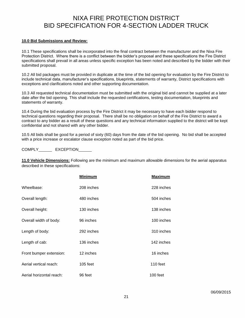
NIXA FIRE PROTECTION DISTRICT BID SPECIFICATION FOR 4-SECTION LADDER TRUCK
06/09/2015
21
10.0 Bid Submissions and Review:
10.1 These specifications shall be incorporated into the final contract between the manufacturer and the Nixa Fire Protection District. Where there is a conflict between the bidder’s proposal and these specifications the Fire District specifications shall prevail in all areas unless specific exception has been noted and described by the bidder with their submitted proposal. 10.2 All bid packages must be provided in duplicate at the time of the bid opening for evaluation by the Fire District to include technical data, manufacturer’s specifications, blueprints, statements of warranty, District specifications with exceptions and clarifications noted and other supporting documentation. 10.3 All requested technical documentation must be submitted with the original bid and cannot be supplied at a later date after the bid opening. This shall include the requested certifications, testing documentation, blueprints and statements of warranty. 10.4 During the bid evaluation process by the Fire District it may be necessary to have each bidder respond to technical questions regarding their proposal. There shall be no obligation on behalf of the Fire District to award a contract to any bidder as a result of these questions and any technical information supplied to the district will be kept confidential and not shared with any other bidder. 10.5 All bids shall be good for a period of sixty (60) days from the date of the bid opening. No bid shall be accepted with a price increase or escalator clause exception noted as part of the bid price.
COMPLY______ EXCEPTION______
11.0 Vehicle Dimensions: Following are the minimum and maximum allowable dimensions for the aerial apparatus
described in these specifications:
Minimum Maximum
Wheelbase: 208 inches 228 inches
Overall length: 480 inches 504 inches
Overall height: 130 inches 138 inches
Overall width of body: 96 inches 100 inches
Length of body: 292 inches 310 inches
Length of cab: 136 inches 142 inches
Front bumper extension: 12 inches 16 inches
Aerial vertical reach: 105 feet 110 feet
Aerial horizontal reach: 96 feet 100 feet

NIXA FIRE PROTECTION DISTRICT BID SPECIFICATION FOR 4-SECTION LADDER TRUCK
06/09/2015
22
Rated tip load: 750 pounds 750 pounds
COMPLY______ EXCEPTION______
NOTE: Each bidder shall submit a complete proposal package and drawing for the unit in accordance with these specifications, any deviations outside of the above dimensions shall be indicated on the drawing.
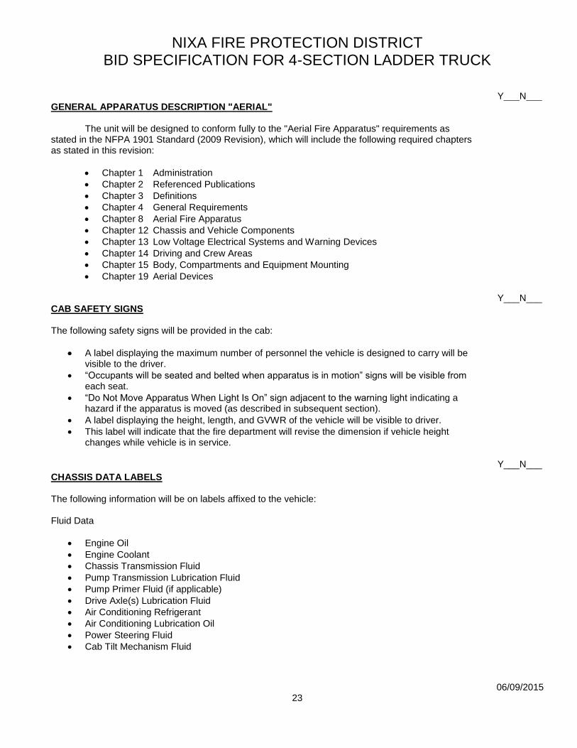
NIXA FIRE PROTECTION DISTRICT BID SPECIFICATION FOR 4-SECTION LADDER TRUCK
06/09/2015
23
Y___N___ GENERAL APPARATUS DESCRIPTION "AERIAL" The unit will be designed to conform fully to the "Aerial Fire Apparatus" requirements as stated in the NFPA 1901 Standard (2009 Revision), which will include the following required chapters as stated in this revision:
Chapter 1 Administration
Chapter 2 Referenced Publications
Chapter 3 Definitions
Chapter 4 General Requirements
Chapter 8 Aerial Fire Apparatus
Chapter 12 Chassis and Vehicle Components
Chapter 13 Low Voltage Electrical Systems and Warning Devices
Chapter 14 Driving and Crew Areas
Chapter 15 Body, Compartments and Equipment Mounting
Chapter 19 Aerial Devices Y___N___ CAB SAFETY SIGNS The following safety signs will be provided in the cab:
A label displaying the maximum number of personnel the vehicle is designed to carry will be visible to the driver.
“Occupants will be seated and belted when apparatus is in motion” signs will be visible from each seat.
“Do Not Move Apparatus When Light Is On” sign adjacent to the warning light indicating a hazard if the apparatus is moved (as described in subsequent section).
A label displaying the height, length, and GVWR of the vehicle will be visible to driver.
This label will indicate that the fire department will revise the dimension if vehicle height changes while vehicle is in service.
Y___N___ CHASSIS DATA LABELS The following information will be on labels affixed to the vehicle: Fluid Data
Engine Oil
Engine Coolant
Chassis Transmission Fluid
Pump Transmission Lubrication Fluid
Pump Primer Fluid (if applicable)
Drive Axle(s) Lubrication Fluid
Air Conditioning Refrigerant
Air Conditioning Lubrication Oil
Power Steering Fluid
Cab Tilt Mechanism Fluid
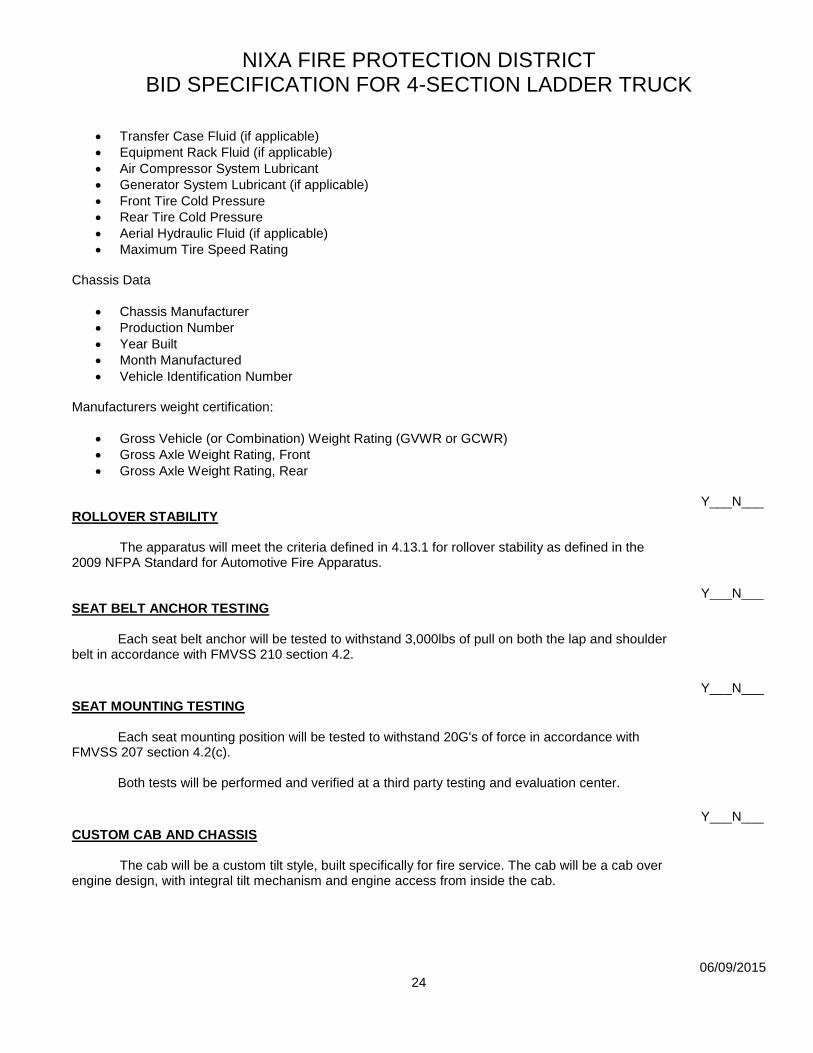
NIXA FIRE PROTECTION DISTRICT BID SPECIFICATION FOR 4-SECTION LADDER TRUCK
06/09/2015
24
Transfer Case Fluid (if applicable)
Equipment Rack Fluid (if applicable)
Air Compressor System Lubricant
Generator System Lubricant (if applicable)
Front Tire Cold Pressure
Rear Tire Cold Pressure
Aerial Hydraulic Fluid (if applicable)
Maximum Tire Speed Rating Chassis Data
Chassis Manufacturer
Production Number
Year Built
Month Manufactured
Vehicle Identification Number Manufacturers weight certification:
Gross Vehicle (or Combination) Weight Rating (GVWR or GCWR)
Gross Axle Weight Rating, Front
Gross Axle Weight Rating, Rear Y___N___ ROLLOVER STABILITY The apparatus will meet the criteria defined in 4.13.1 for rollover stability as defined in the 2009 NFPA Standard for Automotive Fire Apparatus. Y___N___ SEAT BELT ANCHOR TESTING Each seat belt anchor will be tested to withstand 3,000lbs of pull on both the lap and shoulder belt in accordance with FMVSS 210 section 4.2.
Y___N___ SEAT MOUNTING TESTING Each seat mounting position will be tested to withstand 20G's of force in accordance with FMVSS 207 section 4.2(c). Both tests will be performed and verified at a third party testing and evaluation center.
Y___N___ CUSTOM CAB AND CHASSIS The cab will be a custom tilt style, built specifically for fire service. The cab will be a cab over engine design, with integral tilt mechanism and engine access from inside the cab.

NIXA FIRE PROTECTION DISTRICT BID SPECIFICATION FOR 4-SECTION LADDER TRUCK
06/09/2015
25
Cab will be designed, fabricated, assembled in its entirety, and installed on the frame rails in the manufacturer's factory. This requirement will eliminate any split responsibility in warranty and service. Examples of an acceptable Cab and Chassis would be Emergency-One Cyclone II, KME Predator, Pierce Arrow XT, Ferrara Inferno, Seagrave Marauder II, Rosenbauer Commander or comparable.
Y___N___ CRASH TESTING CERTIFICATION To ensure the safety of the cab occupants and cab integrity, proof of third party testing will be provided. The cab will be certified for SAEJ2422 side impact, SAEJ2420 with ECER29 cab front impact, and ECER29 cab roof strength. Furthermore, proof of testing and certification will be provided that the cab, in accordance to SAE J2420 was front impact tested at 2.1 times the standard energy required in SAE J2420, thus exceeding the NFPA requirement. This test will be performed with no support immediately behind the cab, thus providing an
authentic test result.
Y___N___ CAB ROOF The roof will be a flat design with radius edges for an aesthetic, streamline appearance. The roof will be constructed of aluminum skin and will be internally reinforced using extruded aluminum framing which will span the entire width and length of the cab for maximum structural integrity. This will allow the roof to support personnel and roof mounted equipment without the need for additional reinforcement.
Approximate dimensions:
Crew area floor to ceiling 53 1/2"
Top of crew seat to ceiling 35"
Y___N___ CAB ROOF OVERLAY A bright finish aluminum tread plate overlay will be placed on the cab roof, starting at a point rearward of the light bar location and extending back to the end of the cab roof. This tread plate overlay will be sealed with caulking around the edges to prevent moisture from entering the area between the cab roof and the overlay.
NIXA FIRE PROTECTION DISTRICT BID SPECIFICATION FOR 4-SECTION LADDER TRUCK
06/09/2015
26
Y___N___ CAB DOORS Four (4) side-opening doors will be provided. The cab doors will be totally aluminum construction with an extruded aluminum frame and an aluminum outer door skin. Doors will be full height from the step to the cab roof extrusion and enclose the step area when the doors are closed. The forward cab door opening will be a minimum of 37" wide, and the rear cab door opening will be a minimum of 37" wide. The rearward cab doors will have a radius cutout allowing the door opening to protrude forward over the cab wheel well, while providing full access to the rear crew area. There will be a heavy duty piano type stainless steel hinge on each door with a minimum pin diameter of 5/16". Hinges will be slotted for ease of horizontal and vertical adjustment. There will be a cab door seal and the doors will close flush with the side of the cab. A heavy-duty 6" wide belting material will be utilized to prevent the cab doors from opening greater than 90 degrees. An orange web strap shall encircle the cab door stays on all four cab doors. Y___N___ ENTRY STEP AREA Each of the forward entrance steps will be a minimum of 8-1/2" deep with the floor board recessed a minimum of 5" to avoid "shin knocking". Each lower step will be an aluminum tread plate step with Bustin or Nixa FPD approved equal aggressive non-slip surface. The cab steps risers will be overlaid with bright finish aluminum tread plate. Each of the rear entrance steps will be a minimum of 8-1/2" deep. An intermediate step will be provided between the lower entrance step and the crew area floor for ease of entry and egress. Each upper section of the steps and respective step risers will be constructed as an integral part of the cab construction and will be overlaid with bright finish aluminum tread plate. Each lower step will be aluminum tread plate step with Bustin or Nixa FPD approved equal. Y___N___ DOOR LATCHES Heavy-duty, bright finish cast paddle latches will be provided on the interior and exterior of each cab door. Door latch mechanisms which utilize spring steel clamps will not be considered due to their tendency to both rust and break. The interior door latch cables are to be designed to reduce adjustment or possible wear at the adjustment turnbuckles. Y___N___ DOOR WINDOWS Each side cab door will have a tinted retractable window operated by a hand crank mechanism. The window track will be designed into the door frame extrusion, which will be extruded with a track groove to house a window track and seal. The window will be capable of being removed from an access slot designed in the bottom of the door frame. Y___N___ Each side cab door window will be designed with a custom extruded trim plate, which will conform to the perimeter of the window opening in each door. The trim plate will extend from the edge of the door skin to the window and will have a silver anodized finish.

NIXA FIRE PROTECTION DISTRICT BID SPECIFICATION FOR 4-SECTION LADDER TRUCK
06/09/2015
27
Y___N___ INNER DOOR PANELS The cab door interior panels will be covered with a three piece, brushed stainless steel panel, full height. The panel will be 16 gauge stainless steel with a brushed finish and will be designed to allow easy access to the inner door.
Y___N___
Each interior cab door panel will be equipped with reflective ScotchLite material that will cover at least 96 in². Y___N___ EXTERIOR CAB WALL OVERLAY A bright finish aluminum tread plate overlay will be provided over the entire exterior rear cab wall. The tread plate overlay will be sealed with caulking around the edges to prevent moisture from getting between the cab and the overlay. Y___N___ WINDSHIELD/GLASS A two piece, symmetrical, safety glass windshield will be provided on the cab for the driver and officer providing a clear viewing area. The windshields will be full width to the center of the front cab support for each side and provide the occupants with a panoramic view. To provide enhanced peripheral vision on each side of the cab, the windshield and cab structure will be designed with radius corners, which provide a minimum of 8" of glass area, measured from the glass face to the side edge near the door post. The windshield will consist of three (3) layers; the outer light, the middle safety laminate and the inner light. The thick outer light layer will provide superior chip resistance, the middle safety laminate layer will prevent the windshield glass pieces from detaching in the event of breakage and the inner light will provide yet another chip resistant layer. The windshield will be a contour design with 3422 sq. in. of area for improved visibility and style. The windshield glass will be designed so it can be used on either the driver or officer side. Single piece windshields that utilize epoxy or that are bonded to the cab structure will not be acceptable. Y___N___ WINDSHIELD WIPERS AND WASHER Dual, electric operated, pantographic type windshield wipers will be provided. One (1) electric drive motor will be provided for each wiper. Wipers will have "HI/LO" and "INTERMITTENT" operating speeds. "HI/LO" speeds will be controlled by a steering column control, within the turn signal control stem. "INTERMITTENT" operation will be controlled by a twist switch within the control on the steering column. The wipers will be of the self-parking type. Windshield washers will be electric operated wet-arm type with a 3/4 gallon washer fluid reservoir, mounted inside the engine enclosure and readily accessible through the engine hatch at the rear of the engine enclosure. The washer control will be integral with the intermittent wiper control switch.
NIXA FIRE PROTECTION DISTRICT BID SPECIFICATION FOR 4-SECTION LADDER TRUCK
06/09/2015
28
There will be individual removable panels on the front face of the cab for access to the wiper motor assemblies.
Y___N___ WINDSHIELD WIPER DURABILITY CERTIFICATION Windshield wipers will survive testing in excess of 3 million cycles in accordance with section 6.2 of SAE J198 “Windshield Wiper Systems – Trucks, Buses and Multipurpose Vehicles”. The bidder will certify that the wiper system design has been “Third party tested” and that the wiper system has met this criteria. Y___N___ The windows provided on each side of the cab behind the forward cab doors will be deleted. Y___N___ DOT TINT WINDOW GLASS The windshield, all door glass and any viewing window will be provided with standard DOT green automotive tint. Y___N___ GRAB HANDLES Four (4) 1-1/4" diameter x 28" long, knurled, bright anodized aluminum handrails will be provided, one (1) at each cab door entrance. Grab rail stanchions will be chrome plated and offset when necessary to prevent "hand-pinching" when opening or closing the doors. Formed rubber gaskets will be provided between each stanchion base and the cab surface. A brushed stainless steel scuff panel shall be installed behind all exterior cab door hand rails to protect the cab paint. Y___N___ INTERIOR GRAB RAILS Grab rails will be provided to assist in entry and exiting of the cab. Each grab rail will be a cast aluminum "D" style handle that will have a wheelabrated finish and will be located in the following locations:
One (1) 11" long, horizontally mounted, on each front cab door on the interior door panel
One (1) 11" long, horizontally mounted, on each rear cab door on the interior door panel
Y___N___ FRONT CAB GRILL A shaped three-dimensional polished stainless steel grille will be installed to allow for maximum air flow to the charge air cooler and the radiator.
NIXA FIRE PROTECTION DISTRICT BID SPECIFICATION FOR 4-SECTION LADDER TRUCK
06/09/2015
29
Y___N___ AIR INTAKE/OUTLET Two (2) shaped, polished stainless steel air inlets/outlets will be provided horizontally above the wheel well opening, one on each side of the cab. The grilles will be equipped with a mesh screen to serve as a secondary ember separator. The design will permit proper ducting of air through the engine compartment and cooling system.
Y___N___ ENGINE AIR INTAKE SYSTEM The left side inlet, used for the air intake to the air cleaner, will be equipped with dual ember separators for separating burning embers from the air intake system. This system will be such that particles larger than .039 inches (1 mm) in diameter cannot reach the air filter element.
Y___N___ No part of the air intake system for the engine will be lower than the top of the frame rails to ensure the vehicle can navigate pooled water without any part of the air intake system being exposed to water when the vehicle is stopped or in motion. Chassis designs, which the engine air intake system is lower than the frame rails will not be acceptable! Y___N___ WHEEL WELL LINERS The front cab wheel wells will be equipped with fully removable, bolt-in, aluminum inner wheel well liners. The liners will extend full depth into the truck frame. The completely washable wheel well liners will be designed to protect the cab substructure, inner panels, and other miscellaneous installed components from road salts, debris, dirt accumulation and corrosion. Y___N___ FENDERETTES The cab wheel well openings will be trimmed with replaceable, bolt-in, molded black rubber fenderettes. The fenderettes will be secured to the cab with stainless steel threaded fasteners along the internal perimeter of the wheel well Rubber welting will be installed between the fenderettes and the cab side panel Y___N___ FRONT MUD FLAPS Heavy duty, black rubber type mud flaps will be provided behind the front wheels. Y___N___ RETRAC MIRRORS, HEATED, REMOTE CONTROLLED W/ INTEGRAL CONVEX Two (2) Retrac 613305 mirrors will be furnished, one on each front cab door. Each mirror will have a 14-1/2 x 8 flat glass upper head and a 4-1/2 x 8 convex lower head mounted in a one piece chrome plated housing. All heads will be electrically heated, controlled by switching provided by the mirror manufacturer. The upper flat glass portion as well as the lower convex section will be electrically controlled from the driver’s seating position.
NIXA FIRE PROTECTION DISTRICT BID SPECIFICATION FOR 4-SECTION LADDER TRUCK
06/09/2015
30
The stainless steel loop mounting bar will be installed on the forward portion of each front door in front of the side windows with an upper and lower mounting bracket. All switching, bracketing and wiring inside the cab needed for installation of the electric mirrors will be supplied. Y___N___ INTERIOR TRIM The cab interior will be constructed to create an ergonomically designed interior to be user friendly and functional for the driver and officer. The forward overhead panel will be a fabricated module, which will have six (6), 3" diameter, adjustable, windshield defroster/heat vents and four (4) comfort vents. All interior upholstery panels will be gray in color. The upholstered cab overhead and side wall portions will utilize Durawear upholstery with padding underneath to provide additional insulation. Y___N___ The interior metal surfaces of the cab will be finish painted with dark gray Line-X material. Y___N___ INTERIOR REAR WALL The interior rear wall of the cab will be covered with Durawear upholstery. This material will match the other upholstered areas of the cab. Y___N___ UNDER SEAT STORAGE COMPARTMENTS There will be a compartment provided under each front seat. Each compartment will be accessible from the front of the seat riser when the door is opened. Y___N___ BARYFOL FLOORING The floor of the driver’s compartment and the floor of the crew area will be lined with BARYFOL vinyl composite flooring to comply with NFPA noise and heat requirements. The material utilized for this application will be certified to meet the NFPA 1901, 2009 revision for anti-slip walking surfaces.
Y___N___
CAB ACOUSTICAL INSULATION One (1) inch thick acoustical insulation will be provided on the cab roof and rear and side walls of the cab. This material will be fitted between the cab structural members and secured with adhesive to provide an insulation barrier for noise and heat.

NIXA FIRE PROTECTION DISTRICT BID SPECIFICATION FOR 4-SECTION LADDER TRUCK
06/09/2015
31
Y___N___ ENGINE ENCLOSURE The forward portion of the engine enclosure will be covered with a Durawear material formed overlay to match the balance of the cab interior. This Durawear overlay will provide superior cab insulation against noise as well as improved heating and air conditioning performance. The Durawear layer will then be overlaid with formed aluminum panels which will be coated with Line-X to provide a rugged surface for this high wear area. Note: Cab interiors which feature the base aluminum structure painted with high impact resistant paint are not acceptable, the Durawear layer is required between the base structure and the impact panels to provide desired interior conditions. To allow maximum "elbow room" for the driver and officer, the forward portion of the engine enclosure will feature a contour shape. The engine enclosure will not significantly obstruct the driver's vision in any direction. The enclosure will be an integral part of the cab structure, which will be constructed from .250 5052-H32 aluminum, providing adequate strength to support radio, map boxes, etc. The engine enclosure will be insulated to protect from heat and sound. The noise insulation will keep the DBA level within the limits stated in the current NFPA series 1901 pamphlet. A padded, hinged access door will be provided in the top rearward portion of the engine enclosure. The door will allow access to the engine oil, transmission fluid, power steering fluid level dipsticks and the windshield washer fluid reservoir. The access door will be provided with two (2) flush mounted latches and gas shock holders. There will be a Durawear material cover over the access door to give a cleaner look to the top of the engine enclosure and doghouse area. Y___N___ The Line-X overlay panels will be dark gray in color. Y___N___ ADDITIONAL ENGINE ENCLOSURE INSULATION Premium soundproofing/insulation material, Barymat BTRLAX3-14BY will be installed in the engine enclosure. To ensure a clean, smooth surface, this material will be retained by flat aluminum panels fastened to studs that are welded to cab as needed. These panels will be removable. Any gaps in this insulation barrier will be sealed with 3M #425 aluminized high temperature tape. Y___N___ To further reduce the noise and heat levels inside the cab, 1/4" foam upholstery material will be installed on all interior surfaces of the engine enclosure, below the upholstery material.
Y___N___
SUN VISORS To provide maximum protection for the driver and officer, two (2) dark polycarbonate sun visors will be mounted in the cab overhead on each side.
NIXA FIRE PROTECTION DISTRICT BID SPECIFICATION FOR 4-SECTION LADDER TRUCK
06/09/2015
32
Y___N___ ADVANCED OCCUPANT RESTRAINT SYSTEM The cab will be equipped with advanced occupant restraint systems. This system will
function in the event of a side roll over and will be compatible with occupants ranging from a 5th
percentile female to 95th percentile male. This system consists of a roll sensor, seat and occupant pre-tensioners; buckle pre-tensioners and inflatable side airbags. This system will be functionally active while the truck is in operation. A hybrid or pyrotechnic inflator will inflate the side airbags. The bag should remain inflated to the extent of providing head cushioning for 10 seconds after inflation. Pre-tensioners should be compatible with either ABTS or body mounted seats and seat belts. Buckle pre-tensioners will be used on static or power seats where there is no air suspension. The buckle pre-tensioners must be capable of stroking 125 mm.
Y___N___ ROLL SENSOR The roll sensor continually monitors the roll rate and angle of the vehicle, and deploys safety devices when a roll event occurs. Deployment determination is made by a combination of vehicle angle and angular rate. Vehicle deployment angle will never exceed 60 degrees. The roll sensor performs self-diagnostics each time the vehicle is started. A dash-mounted light will turn off after approximately 10 seconds if the sensor is functioning. During operation, the roll sensor monitors for proper connection to each safety device in the vehicle once per second. If improper connection is measured at any device or if an internal fault occurs, the roll sensor will illuminate the dash-mounted light. The system will continue to function in the event of non-critical faults. System diagnostics are on the SAE J1587 bus. Y___N___ DRIVERS SEAT
The driver's seat will be a USSC Valor 12 way electric ABTS LH bucket seat with Side Curtain Airbag. The seat will have a contoured and padded seat cushion with lumbar support. The seat will have a horizontal slide adjustment, a vertical height adjustment, and tilt adjustment and a reclining seat back. All seat movements will be electrically controlled from panel on the forward lower edge of the seat. The seat will be equipped with an ORANGE integrated 3-point shoulder harness with lap belt, and a dual retractor belt configuration with ready reach built into the seat assembly. The Side Air Curtain will be mounted inside the outer bolster of the seat back. The air curtain
will be covered by a panel when in the stored position.
An integrated belt pretension system will be included. When activated the system will
pretension the seat belt.
NIXA FIRE PROTECTION DISTRICT BID SPECIFICATION FOR 4-SECTION LADDER TRUCK
06/09/2015
33
OFFICERS SEAT Y___N___ The officer's seat will be a USSC Valor ABTS RH series fixed base SCBA seat. The seat will have a contoured and padded seat cushion with a dynamic SCBA back frame that adjusts rearward with each occupant to properly seat them against the 20” wide bolster and headrest. The seat will be equipped with magnetic SCBA strap holders which secure the SCBA straps. The Side Air Curtain will be mounted in the outer bolster of the seat. The air curtain will be covered by a panel when in the stored position. The seat will be equipped with an ORANGE integrated 3-point shoulder harness with lap belt, and a dual retractor belt configuration with ready reach built into the seat assembly.
Y___N___ The officer's seat will include a Zico model QLM-U "Quic-Lock" mechanical bottle bracket and restraint assembly. The restraint system will be equipped with an easily accessible mechanical release at the bottom of the assembly. FORWARD FACING, OUTBOARD, DRIVER SIDE SEAT Y___N___ The driver's side outboard forward facing crew seat will be a USSC Valor ABTS LH series fixed base SCBA seat. The seat will have a contoured and padded seat cushion with a dynamic SCBA back frame that adjusts rearward with each occupant to properly seat them against the 20” wide bolster and headrest. The seat will be equipped with magnetic SCBA strap holders which secure the SCBA straps. The Side Air Curtain will be mounted in the outer bolster of the seat back. The air curtain will be covered by a panel when in the stored position. The seat will be equipped with an ORANGE integrated 3-point shoulder harness with lap belt, and a dual retractor belt configuration with ready reach built into the seat assembly. Y___N___ The driver's side outboard forward facing crew seat will have a flip-up style seat. Y___N___ The driver's side forward facing outboard seat will include a Zico model QLM-U "Quic-Lock" mechanical bottle bracket and restraint assembly. The restraint system will be equipped with an easily accessible mechanical release at the bottom of the assembly. Y___N___ FORWARD FACING, OUTBOARD, OFFICER SIDE SEAT The officer's side outboard forward facing crew seat will be a USSC Valor ABTS RH series fixed base SCBA seat. The seat will have a contoured and padded seat cushion with a dynamic SCBA back frame that adjusts rearward with each occupant to properly seat them against the 20” wide bolster and headrest. The seat will be equipped with magnetic SCBA strap holders which secure the SCBA straps.
NIXA FIRE PROTECTION DISTRICT BID SPECIFICATION FOR 4-SECTION LADDER TRUCK
06/09/2015
34
The Side Air Curtain will be mounted in the outer bolster of the seat back. The air curtain will be covered by a panel when in the stored position. The seat will be equipped with an ORANGE integrated 3-point shoulder harness with lap belt, and a dual retractor belt configuration with ready reach built into the seat assembly. Y___N___ The officer's side outboard forward facing crew seat will have a flip-up style seat. Y___N___ The officer's side forward facing outboard seat will include a Zico model QLM-U "Quic-Lock" mechanical bottle bracket and restraint assembly. The restraint system will be equipped with an easily accessible mechanical release at the bottom of the assembly. Y___N___ CENTER FORWARD FACING CREW SEAT One (1) center inboard forward facing crew seat will be a USSC Valor ABTS series SCBA seat. The seat will have a contoured and padded seat cushion with a dynamic SCBA back frame that adjusts rearward with each occupant to properly seat them against the 20” wide bolster and headrest. The seat will be equipped with magnetic SCBA strap holders which secure the SCBA straps. The seat will be equipped with an ORANGE integrated 3-point shoulder harness with lap belt, and a dual retractor belt configuration with ready reach built into the seat assembly. Y___N___ One (1) center inboard forward facing crew seat will have a flip-up style seat. Y___N___ The center forward facing seat will include a Zico model QLM-U "Quic-Lock" mechanical bottle bracket and restraint assembly. The restraint system will be equipped with an easily accessible mechanical release at the bottom of the assembly. Y___N___ FORWARD FACING CREW SEAT RISER The forward facing seats will be mounted on a full width aluminum riser that will be welded
into the cab during cab construction. The riser will match the interior of the cab and will have two (2)
individual, painted aluminum compartment doors with latches, to provide additional storage space in
the cab. The compartment and doors to be sized to hold a medical jump bag that is 32" long x
18" wide x 18" tall (on either side of the compartment).
SEAT UPHOLSTERY MATERIAL Y___N___ The seats will be upholstered with GRAY Cordura material with top stitching as provided by USSC.

NIXA FIRE PROTECTION DISTRICT BID SPECIFICATION FOR 4-SECTION LADDER TRUCK
06/09/2015
35
Y___N___ All seating will have "quick removal" covers.
Y___N___ CAB HELMET STORAGE Each seat position will have a ZICO: Ziamatic UHH-2 Crew Cab Helmet Holder, meeting NFPA 1901, 2009 for a total of four (4) holders. The Driver/Operator will store his/her equipment in the external access compartment behind his/her position. Helmet Holder mounting location will be approved at the engineering conference. Y___N___ SEAT BELT CUSHION SENSORS AND BELT SENSORS The apparatus will be equipped with an Akron/Weldon seat belt warning system. The system will consist of a Seat Belt module, dash mounted display and an audible alarm. Y___N___ Seat belt and seat cushion sensors will be provided on the five (5) specified seating positions. Y___N___ VEHICLE DATA RECORDER An Akron/Weldon Vehicle Data Recorder (VDR) system will be provided. The system will include an NFPA compliant "Black Box" with reporting software that will be capable of data storage to coincide with the NFPA requirements. Data storage capabilities will include interfaces with the following systems:
Display module (Master Optical Warning Device)
VDR, date & time stamp
Max Vehicle speed (MPH)
Vehicle acceleration / deceleration (MPH/Sec.)
Engine Speed (RPM)
ABS event
Data password protected
Data sampled once per second, in 48-hour loop
Data sampled min by min for 100 engine hours
Throttle position (% of Throttle)
Data software
PC / Mac Compatible
Data summary reports. Y___N___ VEHICLE DATA RECORDER DOWNLOAD HARNESS A Weldon model #0L40-2597-00 VDR download harness will be supplied with the system to allow the data to be downloaded to a computer.

NIXA FIRE PROTECTION DISTRICT BID SPECIFICATION FOR 4-SECTION LADDER TRUCK
06/09/2015
36
Y___N___
LINK2 SYSTEM MODULE
The Link2® vehicle diagnostics system captures emergency vehicle data and transmits it
automatically to a secure web dashboard. The data can then be accessed anywhere in the world at any time through a secure account. The Link2 hardware module is mounted on the vehicle and when
within the range of a Wi-Fi network, automatically uploads the data to a web-based dashboard.
The Link2® hardware module will be located in the electrical panel between the driver and
officer and mounted to be completely accessable and removable for programming. A one year subscription for wi-fi (remote) Vehicle Dasboard Access to be provided with the completed vehicle. All required software will either be included or provided as an easy access download to the fire department system. Y___N___ EXTERNAL CAB STORAGE COMPARTMENT WITH HINGED DOOR + INTERNAL ACCESS DOOR A storage compartment will be mounted in the cab in lieu of the driver's side rearward facing crew seat. The compartment will be approximately 23 7/8" deep x 41 3/4 " high x 22 3/4" wide. The door opening will be approximately 35 7/8" high x 20" wide. The compartment will be constructed of aluminum, painted with Line-X matching the interior color of the cab and will be equipped with a hinged flush mount door and an internal access door, latched and painted. The exterior door will have a brushed stainless steel full height interior door panel fitted to the compartment door framework that is equipped with adjustment slots for door hardware. The exterior cab door inner panel will be equipped with reflective Scotchlite material that
will cover at least 96 in². The door will be held in the open position by a gas shock stay arm.
Y___N___ The interior of the compartments will be finish painted with dark gray Line-x scuff resistant paint to provide a protective application over all of the compartment interior surfaces. Y___N___ The EMS compartment will be equipped with one (1) ROM V4 LED interior light(s). The lighting will be wired to automatically activate when the compartment door is open and the master battery switch is in the "on" position. Y___N___ EXTERNAL CAB STORAGE COMPARTMENT WITH A HINGED DOOR + INTERNAL ACCESS DOOR A storage compartment will be mounted in the cab in lieu of the officer's side rearward facing crew seat. The compartment will be approximately 23 7/8" deep x 41 3/4" high x 22 3/4" wide. The door opening will be approximately 35 7/8" high x 20" wide. The compartment will be constructed of aluminum, painted with Line-X matching the interior color of the cab and will be equipped with a hinged flush mount door with a painted finish and an internal access door, latched and painted. The exterior door will have a brushed stainless steel full height interior door panel fitted to the compartment door framework that is equipped with adjustment
NIXA FIRE PROTECTION DISTRICT BID SPECIFICATION FOR 4-SECTION LADDER TRUCK
06/09/2015
37
slots for door hardware. The exterior cab door inner panel will be equipped with reflective Scotchlite
material that will cover at least 96 in². The exterior door will be held in the open position by a gas
shock stay arm. Y___N___ The interior of the compartments will be finish painted with dark gray Line-x scuff resistant paint to provide a protective application over all of the compartment interior surfaces. Y___N___ The EMS compartment will be equipped with one (1) ROM V4 LED interior light(s). The lighting will be wired to automatically activate when the compartment door is open and the master battery switch is in the "on" position. Y___N___ CAB DOGHOUSE STORAGE MODULE A storage module will be installed on the center doghouse area between the driver and officer. The module will be constructed of 1/8" aluminum and will be painted with a scuff resistant paint to match the cab interior. The module will include two (2) cup holders, a pen tray, a flat open storage area for notebooks, six (6) divided storage area's for 3-ring binders, and four (4) slide in storage area's two (2) accessible from each side of the cab. Y___N___ ANTENNA INSTALLATION Two (2) antenna mounting base(s) model #MATM with 17' of coaxial cable will be provided and installed on the lower cab roof, behind the light bar. The attached antenna wire(s) will be run to the right side cab dash area. The Fire Department is responsible to have the correct antenna whip installed once the apparatus is delivered. Y___N___ LAPTOP COMPUTER SLIDE OUT TRAY A slide out tray will be installed for the officer to provide an area for laptop computer usage. In the closed position this area will be nest forward to allow access in and out of the vehicle. Y___N___ DASH & CENTER CONSOLE The dash will be a custom formed, Line-X aluminum housing to create an ergonomically designed interior that will be user friendly and functional for the driver and officer. The instrument cluster will be centered in front of the driver and all gauges will be installed in a non-glare, pewter finish panel. All warning lights and indicators will be located in either the gauge itself or in the lower center portion. Each gauge will be equipped with an international symbol that is easily recognizable; denoting the system being monitored. Instrumentation will be backlit for easy identification when activated.
NIXA FIRE PROTECTION DISTRICT BID SPECIFICATION FOR 4-SECTION LADDER TRUCK
06/09/2015
38
The transmission gear selector will be located on the left side of the center dash assembly, toward the driver for easy access. Y___N___ DRIVER'S DASHBOARD PANEL The main instrument panel will be centered in front of the driver and will have a hinged bottom with two ¼ turn latches at the top. The panel will be made of 1/8” aluminum with an anti-glare, pewter brushed surface and will contain the primary gauges, an instrument warning light cluster and the ignition and engine start switches. The lower portion of this panel can be used for the installation of up to five (5) guarded type rocker switches. Examples of the switches that will be installed in this area are automatic chains, fan clutch over-ride, ATC mud-snow, inter-axle diff lock, electric fuel pump, all wheel drive, etc. The main instrument panel will contain the primary gauges. An ignition and engine start switch will be located on a panel to the left upper portion of the driver's side dash panel. Each gauge will have a raised glass lens with a black matte finish trim ring and be backlit by integral white LED's. Each gauge will also possess an integral red warning light with a pre-programmed warning point. Each gauge warning indicator will be capable of activating an audible alarm inside the dashboard. Y___N___ The primary gauges will consist of:
Vehicle speedometer, (0-80 mph)
Engine tachometer, (0-3000 rpm)
Engine oil pressure, (0-100 psi); low oil warning
Engine coolant temperature (100-280 °F); high engine temp warning
Transmission oil temperature (100-350 °F); high transmission fluid temp warning
Vehicle battery voltage (9-18 VDC); low voltage warning
Front air system gauge (0-150 psi); low air pressure warning at 65 psi
Rear air system gauge (0-150 psi); low oil pressure warning at 65 psi
Fuel level (E - 1/2 - F); low fuel level warning
Air cleaner restriction gauge (0-40), warning at 25"
Y___N___ Additional auxiliary control switches and instruments) will be located within the dash panel located near the driver's position:
Inter axle lock control switch
Diesel Exhaust Fluid level (E-1/2-F); low fuel level warning @ 1/8 tank
Engine Compression Brake Controls
NIXA FIRE PROTECTION DISTRICT BID SPECIFICATION FOR 4-SECTION LADDER TRUCK
06/09/2015
39
Y___N___ INDICATOR CLUSTER The driver's dashboard panel will consist of Ametek gauges, an 18 item instrument warning light cluster and a 16 item, dead front type alarm panel. This display will contain the system control unit that collects data from the vehicle data bus (J1939), analog sensors, and switches throughout the vehicle. This data will be presented using gauges, telltales and the two (2) display panels. The warning light display will include a 2 x 20 dot matrix display, 18 telltales and 2 buttons to navigate through the screen menus. The LCD dot matrix display will be a 2 line by 20-character display with each character being 7 dot by 5 dot configuration. FSTN technology will be used on the display for wide viewing capability. The module will be backlit with amber LED's. The unit will also be supplied with a heater to ensure proper operation over the entire 40 to +85 deg. C. This display contains a series of two (2) screens to provide information about the vehicle. To control the display of that information, the screens are divided into two (2) menus; one that can be displayed while the vehicle is in motion and one that can only be accessed when the parking brake is set. On the Road displays include:
Two (2) configurable displays that can show any of the parameters the unit collects. This includes odometer, trip information, fuel economy information; all gauge data, and virtually any other data available on the vehicle that the display has access to, either through the data bus or via analog inputs.
Two (2) trip displays for miles and hours that are capable of being reset.
Two (2) fuel data screens: will be provided; one for fuel remaining until empty and one for fuel economy. The fuel economy display will be capable of being reset so that average economy over a predetermined period can be displayed.
The displays that can be accessed when the parking brake is set include:
Engine hours as maintained by the engine ECU
Service Alarm screens to report miles to next service or miles past required service. These screens will allow the operator to choose the length of the service interval and will have the ability to reset it.
Message screens with warning messages the display has collected during the current ignition cycle. These screens will be divided into configured warnings such as “Low Air Pressure” and the data bus faults reported by ECU's on the vehicle. Both lists will allow the operator to review the last 12 events that occurred on the vehicle for maintenance and troubleshooting purposes.
Diagnostic screens will test the instrumentation system to verify it is working correctly.
Setup screens will be used to select either English or metric display. They will also allow the operator to choose the data that will be displayed by the configurable on-the-road screens.
NIXA FIRE PROTECTION DISTRICT BID SPECIFICATION FOR 4-SECTION LADDER TRUCK
06/09/2015
40
The system will be configured with user defined warning messages such as Low Air Pressure or High Coolant Temperature. When these events occur the warning message will come up on the screen and can be accompanied by a buzzer. The messages will be prioritized so the most important messages are always displayed. Whether the message can be dismissed by pressing a button will be configurable. Messages that have been dismissed but are still active will be retained in the message screens for review until the ignition is turned off. Listed below are the defined telltales and their indicators.
"Right And Left Directional" arrows (green in color)
"Ignition ON" Indicator (amber in color)
"Hi Beam" indicator (blue in color)
"Battery ON" indicator (green in color)
"Parking Brake ON" indicator (red in color)
"Check Transmission" indicator (amber in color)
"Cab Not Latched" indicator (red in color)
"Stop Engine" indicator (red in color)
"Check Engine" indicator (amber in color)
"ABS Warning" indicator (red in color)
"Low Coolant Level" (red in color)
"Fuel Restriction" indicator (amber in color)
"Water In Fuel" indicator (amber in color)
"Fasten Seat Belts" indicator (red in color)
"Fast Idle" Indicator (amber in color)
"Do Not Move Truck" indicator (red in color)
"DPF Regeneration" (amber in color)
"Exhaust High Temperature" (amber in color)
"Engine Diagnostic Fault" (amber in color)
"Retarder On" (green in color) Listed below are indicators that may be included, depending upon the vehicle configuration:
"Wait To Start" indicator (amber in color)
"Exhaust System Fault" (amber in color)
"Topps System Fault" (amber in color)
"Lube System Active" (amber in color)
"Jacks Not Stowed" (red in color)
"PTO Engaged" (green in color)
"Inter Axle Lock" (amber in color)
"4x4" (green in color)
"Driver Controlled Diff Lock" (green in color)
"Ok to Pump" (green in color)
"Auto Traction Control" (amber in color)
"Retarder Active" (amber in color)
"Auxiliary Brake Active" (amber in color). Y___N___
"Inter Axle Lock" indicator Y___N___
"ATC Disabled" indicator (red in color) Y___N___
"ATC Active" indicator (yellow in color)
NIXA FIRE PROTECTION DISTRICT BID SPECIFICATION FOR 4-SECTION LADDER TRUCK
06/09/2015
41
Y___N___
"Outrigger(s) Extended" indicator light Y___N___ LOWER RIGHT AUXILIARY SWITCH PANEL The driver’s lower right panel will be capable of housing five (5) guarded type rocker switches. Examples of the switches that will be installed in this area are automatic chains, fan clutch over-ride, ATC, inter-axle diff lock, electric fuel pump, all wheel drive, etc.
Y___N___
AERIAL POWER CONTROLS There will be an aerial device power and a PTO engagement switch located in the cab switch console. An aerial device PTO/hour meter will be furnished adjacent to the power switches. See ladder description for details. Y___N___ MOBILE TERMINAL AREA There will be a flat surface area in front of the officer for placement of a laptop computer. Y___N___ CENTER OVERHEAD PANEL An overhead console with a removable pewter panel will be provided on the cab roof between the driver and officer to permit installation of cab stereo, intercom systems, arrow stick controls, etc. The overhead console will be approximately 27" wide x 4" high x 13" deep and will be painted to match the interior of the cab. The overhead console will not obstruct the driver's vision through the officer's side window. Y___N___ CLIMATE CONTROL SYSTEM System will be a dual roof mounted SGM air conditioning system capable of cooling a heat soaked cab interior temperature of 100°F down to 73°F in 30 minutes with an outside ambient air temperature of 100°F and 50% humidity. System will utilize one (1) International Components Engineering #TM-31 HD compressor, mounted as close to level as practicable. The compressor will have a serpentine Poly "V" drive belt system installed in accordance with the compressor and belt manufacturer's requirements. Air conditioning hoses and fittings will be appropriately sized to the compressor and other specified air conditioning components. Minimum hose size, will be #10 hose for discharge and #12 hose for suction. Steel hose end fittings will be provided at the compressor. The air conditioner hose will be the Aeroquip “Easy Clip” style hoses as recommended by Aeroquip. The A/C hoses will utilize FC802 Aeroquip hose with re-usable JIC 37 degree fittings. One (1) condenser, rated at a minimum of 65,000 BTU with a minimum 2,500 CFM output will be provided on the cab roof. Both the front and rear overhead units will include the heating units.

NIXA FIRE PROTECTION DISTRICT BID SPECIFICATION FOR 4-SECTION LADDER TRUCK
06/09/2015
42
Two (2) evaporators, each rated at a minimum of 25,000 BTU, with a minimum blower output of 400 CFM through the louvers will be provided. Both evaporator units will be mounted on the cab roof, enclosed by aluminum panels painted white. The evaporator louvers and controls will penetrate the cab roof into occupant compartments to the least extent practicable. Thirteen (13) 3" diameter adjustable louvers will be furnished, six (6) in the front crew area and seven (7) in the rear crew area of the cab. The A/C drain lines will be routed to the inside of the cab wheel well area. Draining condensation into the interior of the cab or onto the occupants, roof or windshield will not be acceptable under any conditions. System will be compatible with R134A refrigerant. The 12-volt system for the air conditioners will have first priority to be load managed. System will utilize clearly labeled automatic reset-type circuit breakers. The master air conditioning on/off control switch will be provided in the driver's compartment. Fan speed controls will be provided for each evaporator unit to individually regulate air circulation with or without the air conditioning system being activated. The controls panel will actuate the air-distribution system with air cylinders, which are to be separated from the brake system by an 85-90 psi pressure protection valve. The air conditioning system will be configured to only operate when the vehicle's engine is running. The blowers, in both evaporators, will be in operation whenever the air conditioning system is activated. If either the front or rear evaporator fan speed switches is in the "off" position, then the evaporator blower in the "off" position will default to low speed. Both the front and rear overhead units will include the heating units. Heater-defroster will have a three-speed electric fan with a minimum output of 350 CFM through the louvers. Six (6) 3" diameter adjustable defroster outlets will be provided for directing warm air to the windshields. Heater-defroster unit controls will be illuminated. Water lines from the engine to heater-defroster will be 5/8" heater hose with readily accessible flexible connections at each end. The water lines to the heater will have shut-off valves mounted on the engine to isolate the heater-defroster unit. The heater hose installation will not incorporate a copper tube manifold. The heater/defroster unit will clear the windshield in half-the-time required by SAE Standards. A serviceable foam intake filter will be installed on the rear of the evaporator. All defrost/heating systems will be plumbed with one (1) seasonal shut-off valve mounted near the engine. Y___N___ ROOF MOUNT CONDENSERS Two (2) 12-volt, roof top, single condensers will be mounted on the cab roof so as not to interfere with the aerial device or any emergency lighting systems. The condensers will be designed with high performance, long life fan assemblies. The fan motors are to be equipped with sealed housings and shaft. The condenser covers will be white in color to match the cab roof.

NIXA FIRE PROTECTION DISTRICT BID SPECIFICATION FOR 4-SECTION LADDER TRUCK
06/09/2015
43
The condensers and coil design will include rifled tubing for maximum efficiency. Each coil will be painted black. The condenser unit will include a receiver drier with a high and low pressure switch. The wire harness will include necessary wiring for the clutch circuit as well as a separate power relay circuit. Mounting design will enable easy servicing of all components and unit replacement if necessary. Y___N___ CLIMATE CONTROL SWITCHES The drivers overhead panel will contain all controls for the cab climate control system. The following controls will be provided: mode selector switch, front fan speed switch, rear fan speed switch, air conditioning on/off switch, and temperature switch. All switches will be clearly labeled, adequately backlit, and installed in an easily removable panel. Y___N___ CAB DEFOGGER FANS Two (2), six (6) inch diameter, two-speed, all metal component, defogger fans will be provided in addition to the standard windshield defroster. Y___N___ CAB TILT ASSEMBLY A hydraulic cab lift system will be provided, consisting of an electric-powered hydraulic pump, fluid reservoir, dual lift cylinders, remote cab lift controls and all necessary hoses and valves. The cab tilt mechanism will be custom designed for ease of maintenance and consist of two (2) hydraulic cylinders with a maximum lift capacity of 19,625 pounds. Hydraulic lines will be rated at 20,000 PSI burst pressure. The hydraulic cylinders will be equipped with a velocity fuse that protects the cab from accidentally descending when the cab is in the tilt position. Hydraulic cylinders will be detachable to allow removal of the engine for major service. A remote cable operated mechanical cylinder stay bar and release will be provided to insure a positive lock in the tilted position. The two (2) rear outboard cab latches will be of the hydraulic pressure release, automatic re-latching type, and provide an automatic positive lock when the cab is lowered. The latch will not disengage or experience any damage when subjected to a pull apart tensile load of 6,000 lbs. The hydraulic pressure required to unlock the latch will not exceed 550 PSI. The latch will withstand 5,000 PSI without leaks or damage and withstand 1,000 continuous cycles of operation under a load of 1,000 lbs at liftoff. The tilt pump will be electric over hydraulic type, with a pressure rating of not less than 4,000 PSI. Additionally, the cab tilt device will be both electrically and hydraulically interlocked to prevent inadvertent activation of the cab tilt system.
A "CAB NOT LATCHED" indicator will be provided in the cab dash-warning cluster.
A dual switch control system will be provided for the cab tilt, located on the passenger side of the vehicle or on the optional tether control. System will consist of a three (3) position toggle switch along with a rubber covered push button switch.

NIXA FIRE PROTECTION DISTRICT BID SPECIFICATION FOR 4-SECTION LADDER TRUCK
06/09/2015
44
Y___N___ AUXILIARY MANUAL CAB LIFT An auxiliary manual cab lift backup system will be furnished inside the passenger side forward locker compartment for use in the event of total electrical shutdown. The unit will have a protective cover to prevent damage. Y___N___ The cab tilt control will be equipped with an interlock that will disable the cab tilt system in the event the parking brake is not applied. Y___N___ CHASSIS FRAME ASSEMBLY The chassis frame will be fabricated in its entirety at the manufacturer's facility. This will prevent any split responsibility in warranty or service. The frame will consist of two (2) channels fastened together by cross members. All structural fasteners used in the frame will be Grade 8 hardware. Hardened steel washers will be used under all bolt heads and nuts to avoid stress concentrations. Top flange will be free of bolt heads. All spring hangers will be machined steel castings. Weldment type chassis and the use of Huck bolts will never be used. Each main frame rail will be 10-1/4" x 4" x 3/8", fabricated from 110,000 PSI minimum yield steel, with a minimum section modulus of 18.396 cu in and a resisting bending moment (RBM) of 2,023,560 inch pounds. A full length inner frame liner will be installed. Total section modulus of each rail, with liner, will be 33.555 cu in and the total resisting bending moment (RBM) will be 3,691,050 in-lbs, per rail. A third inner frame liner will be provided between the front and rear axle spring hangers. Total section modulus of each rail, with both liners, will be 42.180 cu in and the total resisting bending moment (RBM) will be 4,639,800 in-lbs, per rail. The chassis frame assembly, consisting of frame rails, cross members, axles and steering gear(s), will be finish painted job color before installation of any electrical wiring, fuel system components, or air system components. All components or brackets fastened to the frame rails will be cleaned, primed and painted prior to being attached to the frame rails. Y___N___ PAINTED STEEL FRONT BUMPER A 12" high, 101" wide, painted steel front bumper will be provided. The bumper will be constructed from 3/8" steel, which will be designed with 45-degree welded corners and a 2" flange on the top and bottom. The ends of the bumper will be supported by horizontal channels, which will extend from the frame rails to the sides of the bumper. The color of the bumper will match the cab and body base color. The top flange of the bumper will be protected with either brushed stainless steel or job color Line-X to prevent this painted area from damage.

NIXA FIRE PROTECTION DISTRICT BID SPECIFICATION FOR 4-SECTION LADDER TRUCK
06/09/2015
45
Y___N___ BUMPER EXTENSION The bumper will be extended 12" with a polished aluminum tread plate gravel shield enclosing the top and ends. Y___N___ The polished aluminum tread plate gravel shield will terminate under the top bumper flange.
Y___N___ FRONT TOW HOOKS Two (2) front painted tow hooks will be fastened directly to the frame, below the front bumper. The tow hooks will be fastened with grade 8 bolts and nuts. The tow hooks will be the lowest point on the front of the vehicle ahead of the front axle to protect all fixed chassis components in this area. Y___N___ AERIAL TRAVEL SUPPORT An aerial travel support for the aerial device will be provided and located as close to the front axle as possible. Y___N___ FRONT AXLE Front axle will be a Meritor MFS-20-133 A-N, includes low friction "Easy Steer" bushing technology for maximum steering ease and longer life. The front axle will be rated at 23,000 lbs. Y___N___ FRONT DISC BRAKES Meritor EX-225 H, 17" disc brakes will be provided for the front axle. The front brakes will be full air actuated with automatic slack adjustment. Y___N___ Premium Stemco oil seals with viewer glass will be provided on the front axle. Y___N___ FRONT SUSPENSION Front suspension will be progressive rate front leaf springs. The spring will be permanently pinned at the front and have a shackle double pinned mounting at the rear. The front leaf springs will have a minimum of 10 leaves, a minimum length of 51", and a minimum width of 3-1/2". The capacity at ground will be 23,000 lbs. All springs will be of center bolt design. All spring pins will be positively restrained from rotating in brackets and shackles.

NIXA FIRE PROTECTION DISTRICT BID SPECIFICATION FOR 4-SECTION LADDER TRUCK
06/09/2015
46
Y___N___ FRONT SHOCK ABSORBERS The front suspension system will be equipped with Monroe, model "Magnum - 70", double acting hydraulic shock absorbers. Shock absorbers to have a minimum bore of 1.38" and an outside diameter of approximately 3-1/4". Y___N___ REAR AXLE Rear axle assembly will be a tandem, Meritor RT-52-185 single reduction with a capacity of 54,000 lbs. Axles will have a gear reduction as required. A driver controlled Power Divider Lock (PDL), will allow full driveshaft torque to be sent to both rear axles in low traction situations when a tire on one axle is slipping. This feature will be disengaged during normal driving to prevent interaxle differential damage. An electric over air-operated switch will be provided in the cab driver dash area. Oil seals will be provided as standard equipment. Y___N___ REAR DISC BRAKES Meritor EX-225, 17" disc brakes will be provided for the rear tandem axles. The rear brakes will be full air actuated with automatic slack adjustment. Y___N___ REAR AXLE TOP SPEED The rear axle/s will be geared for a vehicle top speed of 60 MPH in accordance with NFPA sections 4.15.2 and 4.15.3. Y___N___ REAR SUSPENSION A Ridewell 202S, "Dynalastic" rubber block suspension will be provided for the tandem rear axle assembly. The suspension will have a weight rating equal to the rear axle weight rating up to 58,000 pounds. Y___N___ SKF- VOGEL LUBE SYSTEM An SKF- Vogel model KFU-2-40 lubrication system will be provided to automatically lubricate the chassis steering and suspension components. The system will be an electrically operated gear pump and will have a 6 lb. grease reservoir. The pump will be capable of lubricating up to 150 lubrication points. The reservoir is topped up with lubricant via a quick disconnect fitting. The pump is designed to use fluid grease of NLGI grades 000 and 00. An IC 433-5-51-system control unit mounted in the cab will activate the system. Vehicle ignition on time is used to start the monitoring cycle. Adjustable time settings ranges from 1/2 to 11 hours will be provided. The control unit will be equipped with a nonvolatile memory and impervious to EMF interference. The control unit will have a manual reset button which activates the system for intermediate lube cycle or diagnostic self test for
NIXA FIRE PROTECTION DISTRICT BID SPECIFICATION FOR 4-SECTION LADDER TRUCK
06/09/2015
47
system power on, pump motor on, and system pressure attainment. An indicator lamp will be provided in the cab for visual monitoring of system performance. Piston distributors are available in 2, 4 or 6 port configurations and can be ganged together for larger point requirements. Each individual port addresses a single lubrication point, and has metering range of 0.003 to 0.06 cu. in. per cycle. Metering nipples are field interchangeable to allow for quick adjustment to extraordinary lube point requirements. Tubing from distributor to lube point will be color-coded to match specific distributor outputs allowing for easy visual identification for maintenance or replacement. Should a lubrication point be unable to immediately accept lubricant at that time due to a "loaded" condition, the spring pressure is maintained until load shifts/chassis movement/road conditions, unload the bearing permitting lubricant to flow to the lubrication point, which is then lubricated by the still loaded piston. The auto-lube system will be installed and tested by the apparatus manufacturer. Y___N___ BRAKE SYSTEM A dual circuit, air operated braking system, meeting the design and performance requirements of FMVSS -121 and the operating test requirements of NFPA 1901 current edition will be installed. It will be direct air type with dual air treadle in the cab. The system will be powered by an engine mounted, gear driven air compressor protected by a heated air dryer. The air system will be plumbed with reinforced, air brake tubing/hose in conformance to SAE J 844-94, Type B and U.S.D.O.T. standards. The compressor discharge will be plumbed with stainless steel braided hose lines with a Teflon lining. Eaton Synflex Eclipse Air Brake tubing will be run along the inside frame rails and connected with push to connect type fittings that meet or exceed all industry standards. All Synflex will be secured with non-conductive, corrosion resistant strapping mounted with standoff fasteners. Cord reinforced rubber hose lines with brass fittings will be installed from the frame rails to axle mounted air connections. The air system will provide a rapid air build-up feature and low-pressure protection valve with light and buzzer, designed to meet the requirements of NFPA 1901, current edition.
Y___N___
ABS SYSTEM An Anti-Skid Braking System (ABS) will be provided to improve braking control and reduce stopping distance. This braking system will be fitted to all of the axles. All electrical connections will be environmentally sealed, water, weatherproof, and vibration resistant. The system will constantly monitor wheel behavior during braking. Sensors on each wheel will transmit wheel speed data to an electronic processor which will sense approaching wheel lock causing instant brake pressure modulation up to 5 times per second in order to prevent wheel lockup. Each wheel will be individually controlled. To improve service trouble shooting, provisions in the system for an optional diagnostic tester will be provided. The system will test itself each time the vehicle is started. A dash-mounted light will go out once the vehicle has attained 4 mph after successful ABS start-up. To improve field
NIXA FIRE PROTECTION DISTRICT BID SPECIFICATION FOR 4-SECTION LADDER TRUCK
06/09/2015
48
performance; the system will be equipped with a dual circuit design. The system circuits will be configured in a diagonal pattern. Should a malfunction occur, the defective circuit will revert to normal braking action. A warning light will signal malfunction to the operator. The system will consist of a wheel mounted toothed ring, sensor, sensor clip, electronic control unit and solenoid control valve. The sensor clip will hold the sensor in close proximity to the toothed ring. An inductive sensor consisting of a permanent magnet with a round pole pin and coil will produce an alternating current with a frequency proportional to wheel speed. The unit will be sealed, corrosion resistant and protected from electromagnetic interference. The electronic control unit will monitor the speed of each wheel. A deviation will be corrected by cyclical brake application and release. If a malfunction occurs, the defective circuit will signal the operator and the malfunctioning portion of the system will shut down. The system will be installed in a diagonal pattern for side-to-side control. The system will insure that each wheel is braking to optimum efficiency up to 5 times a second. The system will also control application of the auxiliary engine exhaust or drive line brakes to prevent wheel lock. This system will have a three (3) year or 300,000 mile parts and labor warranty as provided by Meritor Wabco Vehicle Control Systems. Y___N___ ELECTRONIC STABILITY CONTROL (ESC) Electronic Stability Control (4 or 6 Channel) will be provided as part of the Standard ABS system. The Electronic Stability Control system will be capable of recognizing and assisting in both rollover and vehicle-under and over-steer situations through advanced monitoring of vehicle parameters and automatic and selective application of the chassis brakes. The Electronic Stability system will use lateral and yaw accelerometers, wheel speed sensors, ABS pressure modulator valves and an ECU to control the four corners of the vehicle. The controller will monitor the vehicle response to turning and braking, and adjust or modulate the brake pressure at the wheel end to slow the vehicle in roll control, stabilize the vehicle when under or over steering, and modulate brake pressure when excessive wheel slip, or wheel lockup is detected. By these actions, the ESC system will help to maintain vehicle lateral and roll stability, improve braking and steering during heavy brake applications and braking on slippery surfaces. Y___N___ AUTOMATIC TRACTION CONTROL (ATC) To further improve vehicle drive characteristics, the unit will be fitted with automatic traction control (ATC). This system will control drive wheel slip during acceleration from a resting point. An extra solenoid valve will be added to the ABS system. The system will control the engine and brakes to ensure efficient acceleration. The system will be equipped with a dash-mounted light indicating the ATC is controlling drive wheel slip. The system will also include an "off road traction" dash mounted switch that will allow the operator to momentarily allow for more wheel slip when the unit is in deep mud or snow. This system will have a three (3) year or 300,000 mile parts and labor warranty as provided by Meritor Wabco Vehicle Control Systems.

NIXA FIRE PROTECTION DISTRICT BID SPECIFICATION FOR 4-SECTION LADDER TRUCK
06/09/2015
49
Y___N___ BRAKE AIR RESERVOIRS There will be a minimum of four (4) air reservoirs and be installed in conformance with best automotive practices. An additional 1200 cu. in. air reservoir will be provided for the accessory air outlet. Reservoir capacity total will be a minimum of 8300 cu. in. The air reservoirs will be color coded to match the air lines for easy identification, ease of maintenance and troubleshooting. The reservoirs will be painted the following colors:
Wet Tank Black
Primary Tank Green
Secondary Tank Blue
Auxiliary Tank(s) Yellow Y___N___ STAINLESS STEEL AIR TANK BRACKETS Stainless steel air tank brackets will be provided to secure the air tanks to the chassis frame. Y___N___ PULL CABLE DRAINS For ease of daily maintenance, each air system reservoir will be equipped with pull cable type drains, which will be extended to the edge of the body or running board. Y___N___ AIR DRYER A Bendix AD-9, 12 volt heated air dryer will be furnished. An automatic moisture ejector on the primary or wet tank will also be furnished. Y___N___ AIR LINES The entire chassis air system will be plumbed utilizing reinforced, Synflex air lines. All of the airlines will be color coded to correspond with an air system schematic and will be adequately protected from heat and chafing. Y___N___ AIR COMPRESSOR Air compressor will be a Wabco brand, minimum of 18.7 cubic feet per minute capacity. Air brake system will be the quick build up type. The air compressor discharge line will be stainless steel braid reinforced Teflon hose. A pressure protection valve will be installed to prevent the use of air horns or other air operated devices should the air system pressure drop below 80 psi (552 kPa).

NIXA FIRE PROTECTION DISTRICT BID SPECIFICATION FOR 4-SECTION LADDER TRUCK
06/09/2015
50
The chassis air system will meet NFPA 1901, latest edition for rapid air pressure build-up within sixty (60) seconds from a completely discharged air system. This system will provide sufficient air pressure so that the apparatus has no brake drag and is able to stop under the intended operating conditions following the sixty (60) seconds build-up time. Y___N___ BRAKE TREADLE VALVE A Bendix dual brake treadle valve will be mounted on the floor in front of the driver. The brake control will be positioned to provide unobstructed access and comfort for the driver. Y___N___ PARKING BRAKE Parking brake will be of the spring-actuated type, mounted on the rear axle brake chambers. The parking brake control will be mounted on the cab center instrument panel. A red indicator light will be provided in the driver dash panel that will illuminate when the parking brake is applied. The parking brake will be plumbed to provide all wheel lock-up when applied. Y___N___ FRONT WHEELS & TIRES The front wheels will be 22.5" x 13" ten stud, hub piloted polished aluminum disc type. Y___N___ The aluminum disc front wheels will be provided with bright nut covers and hub caps. Y___N___ The front tires will be Michelin 425/65R22.5 "20 Ply" tubeless radial XFE wide base highway tread. The tires will be fire service rated up to 24,400 lbs and will have a top speed of 75 mph when inflated to 120 psi. Fire Service Rating means operations not to exceed one hour loaded travel at maximum speed, with at least a one hour cool down prior to another loaded run. Y___N___ REAR WHEELS & TIRES The tandem rear axle wheels will be 22.5" x 9" ten stud, hub piloted polished aluminum disc type. Y___N___ The tandem rear aluminum disc wheels will be provided with bright nut covers and hub caps. Y___N___ The rear tires will be Michelin 315/80R22.5 "20 Ply" tubeless radial XDN2 GRIP traction tread. The tires will be fire service rated up to 67,000lbs and will have a top speed of 60 mph when inflated to 130 psi.
NIXA FIRE PROTECTION DISTRICT BID SPECIFICATION FOR 4-SECTION LADDER TRUCK
06/09/2015
51
Fire Service Rating means operations not to exceed one hour loaded travel at maximum speed, with at least a one hour cool down prior to another loaded run. Y___N___ TIRE PRESSURE MONITORING DEVICES Each tire will be equipped with an LED tire alert pressure management system (Vecsafe equal) that will monitor tire pressure. A chrome plated brass sensor will be provided on the valve stem of each tire. The sensor will calibrate to the tire pressure when installed on the valve stem for pressures between 20 and 120 psi. The sensor will activate an integral battery operated LED when the pressure of that tire drops 8 psi. Removing the cap from the sensor will indicate the functionality of the sensor and battery. If the sensor and battery are in working condition, the LED will immediately start blinking. Y___N___ VALVE EXTENSION STABILIZERS The rear tire and wheel assemblies will be equipped with valve extensions and stabilizers. ENGINE Y___N___ Engine will be a Cummins, Model ISX12 500, diesel, turbo-charged, per the following specifications.
Max. Horsepower 500 HP @ 1800 RPM
Governed Speed 2100 RPM
Peak Torque 1645 lb. ft. @ 1100 RPM
Cylinders Six (6)
Operating Cycles Four (4)
Bore & Stroke 5.11 x 5.91 in.
Displacement 729 cu. in.
Compression Ratio 16.6:1
Governor Type Limiting Speed
Drive line Size 1810 Series. Y___N___ Engine oil filters will be engine manufacturers branded or approved equal. Engine oil filters will be accessible for ease of service and replacement. Y___N___ A fuel/water separator will be provided. Y___N___ ENGINE CHASSIS CERTIFICATION

NIXA FIRE PROTECTION DISTRICT BID SPECIFICATION FOR 4-SECTION LADDER TRUCK
06/09/2015
52
The engine will be installed in accordance with engine manufacturer's instructions. The apparatus manufacturer will be able to furnish proof of engine installation approval by the engine manufacturer. Y___N___ COOLING/RADIATOR The radiator and the complete cooling system will meet or exceed NFPA and engine manufacturer cooling system standards. To provide maximum corrosion resistance and cooling performance, the entire radiator core will be constructed using long life aluminum alloy. The core will be made of aluminum fins, having a serpentine design, brazed to aluminum tubes. The tubes will be brazed to aluminum headers. No solder joints or leaded material of any kind will be acceptable in the core assembly. The radiator core will have a height of 35.92" x a width of 37.62". Supply and return tanks made of glass-reinforced nylon will be crimped on to the core assembly using header tabs and a compression gasket to complete the radiator core assembly. The radiator will be compatible with commercial antifreeze solutions. There will be a full steel frame around the entire radiator core assembly. The radiator core assembly will be isolated within the steel frame by rubber inserts to enhance cooling system durability and reliability. The radiator will be mounted in such a manner as to prevent the development of leaks caused by twisting or straining when the apparatus operates over uneven ground. The radiator assembly will be isolated from the chassis frame rails with rubber isolators. The cooling system will include a surge tank mounted to the top of the radiator framework that will remove air in the system. The surge tank will be equipped with a sight glass to monitor the level of coolant. The radiator will be equipped with a dual seal cap that will allow for expansion and recovery of coolant into a separate integral chamber. The cooling system will be designed for a maximum of fifteen (15) PSI operation. A drain port will be located at the lowest point of the cooling system and/or the bottom of the radiator to permit complete flushing of the coolant from the system. Extended life engine coolant will provide anti-freeze protection to -30° F. The mixture will be per the engine manufacture's specifications. Y___N___ The engine cooling system will have an inline coolant filter that will have a shut off valve for ease of maintenance. Y___N___ The engine cooling system will be certified by the engine manufacturer to meet cooling index requirements for a minimum ambient temperature or 110-degrees Fahrenheit. Y___N___ TRANSMISSION COOLER
A shell and tube transmission oil cooler will be provided using engine coolant to control the transmission oil temperature. The cooler will have an aluminum shell and copper tubes. The cooler

NIXA FIRE PROTECTION DISTRICT BID SPECIFICATION FOR 4-SECTION LADDER TRUCK
06/09/2015
53
will be assembled using pressed in rubber tube sheets to mechanically create a reliable seal between the coolant and the oil. No brazed, soldered, or welded connections will be used to separate the coolant from the oil. Y___N___ RADIATOR SKID PLATE The radiator installation will include a heavy-duty radiator skid plate to protect the radiator from debris or obstructions under the chassis. The skid plate will be designed so the angle of approach is not effected. Y___N___ CHARGE AIR COOLER The charge air cooler will be constructed of aluminum with cast aluminum side tanks. To not restrict air flow to the radiator, the charge air cooler will designed to be an integral part of the radiator assembly, mounted directly on top of the radiator. Rubber isolators will be used at the mounting points to reduce transmission of vibrations. Where applicable, the charge air cooler pipes will be constructed of appropriately sized aluminized steel tubing with 0.06” wall thickness and formed hose barbs. The connections between these pipes, the engine and charged air cooler, will be made using high temperature silicone hoses rated for use in temperature up to 500°F, and heavy duty constant tension T-Bolt spring hose clamps. These connections will adequately allow for movement of the engine relative to the charged air cooler. Charge air coolers that are located in front of the radiator, that block or restrict air flow into the engine radiator or introduce above ambient temperature air into the radiator in any way will not be used. Y___N___ COOLING SYSTEM FAN The engine cooling system will incorporate a heavy duty fan, installed on the engine and include a shroud. The fan will be equipped with an air operated clutch fan, which will activate at a pre-determined temperature range. Recirculation shields will be installed to ensure that air which has passed through the radiator is not drawn through it again. Y___N___ COOLANT HOSE AND PIPING All coolant piping will be constructed of appropriately sized powder coated steel tubing with 0.06” wall thickness and formed hose barbs. All connections between coolant pipes and chassis components will be made using appropriately sized silicone hoses or elbows, rated for use in temperatures ranging from -60°F to +350°F, and appropriately sized constant torque hose clamps. These connections will be minimal in number to reduce the number potential leak points, and will adequately allow for movement of the engine relative to chassis mounted components. All integral hoses supplied with the engine will be as supplied by the engine manufacturer.
NIXA FIRE PROTECTION DISTRICT BID SPECIFICATION FOR 4-SECTION LADDER TRUCK
06/09/2015
54
Y___N___ HEATER HOSES Premium Goodyear Hi-Miler® blue heater hoses will be furnished for the heater system. The Hi-Miler® hose will have a core of black Versigard (EPDM) with spiral Flextan reinforcement and blue Versigard coating. All heater hoses will be equipped with constant torque type hose clamps. All integral hoses supplied with the engine will be as supplied by the engine manufacturer. Two (2) mechanical shut off valves will be installed on the engine to shut down the flow of coolant to the cab heating system. Y___N___ LOW COOLANT INDICATOR LIGHT AND ALARM A low engine coolant indicator light located in the dash instrument panel will be provided. An audible alarm will be provided to warn of the low coolant condition. Y___N___ ENGINE BRAKE An engine compression brake (Jacob’s Type – Not an exhaust brake) will be furnished for increased braking capabilities. Controls will be as provided by the engine manufacturer and will be activated by releasing the throttle pedal to the idle position. The engine compression brake will have dash mounted control switches to turn the brake on or off as well as to control the operational level of the brake. The engine brake will be wired in such a manner so as to illuminate the chassis brake lights when the engine brake is engaged and operating. The engine brake will be interlocked with the PTO operation and will automatically disengage any time the apparatus is operating with the PTO active. Y___N___ ENGINE FAST IDLE A fast idle for the electronic controlled engine will be provided. The fast idle will be controlled by switches located on the dash or the optional smart wheel. An electronic interlock system will prevent the fast idle from operating unless the transmission is in "Neutral" and the parking brake is fully engaged. If the fast idle control is used in conjunction with a specified engine/transmission driven component or accessory, the fast idle control will be properly interlocked with the engagement of the specified component or accessory. Y___N___ AIR CLEANER An engine air cleaner will be provided. The air cleaner will include a dry type element and will be installed in accordance with the engine manufacturer's recommendations. The air cleaner will be located to the rear of the engine, with streamline air pipes and hump hose connections from the inlet to the air cleaner and from the air cleaner to the turbo. The air cleaner will be easily accessible when

NIXA FIRE PROTECTION DISTRICT BID SPECIFICATION FOR 4-SECTION LADDER TRUCK
06/09/2015
55
the cab is tilted. The air cleaner will be plumbed to the air intake system that will include a self-sealing connection between the cab and air cleaner assembly to allow the cab to be tilted. Y___N___ SPARK ARRESTOR A spark arrestor will be installed in the chassis air intake system. This arrestor will be mounted behind the intake grille to filter out airborne embers. The spark arrestor housing must be easily accessible when the cab is tilted. Y___N___ ACCELERATOR CONTROL A floor mount accelerator pedal will be installed on the floor in front of the driver. The pedal will be positioned for comfort with ample space for fire boots and adequate clearance from the brake pedal control. Y___N___ REMOTE THROTTLE CONTROL HARNESS An apparatus interface wiring harness for the engine will be supplied with the chassis. The harness will include a connector for connection to the chassis harness which will terminate in the left frame rail behind the cab for reconnection to required throttle control harnesses. The harness will contain necessary connectors for a pressure governor and a multiplexed gauge. Separate circuits will be included for pump controls, “Pump Engaged” and “OK to Pump” indicator lights, open compartment ground, start signal, park brake ground, ignition signal, master power, customer ignition, air horn solenoid switch, high idle switch and high idle indication light. An apparatus interface wiring harness will also be included which will be wired to the cab harness interface connectors and will incorporate circuits with relays to control pump functions. This harness will control the inputs for the transmission lock up circuits, governor/hand throttle controls and dash display which will incorporate “Pump Engaged” and “OK to Pump” indicator lights. The harness will contain circuits for the apparatus builder to wire in a pump switch.
Y___N___
TRANSMISSION An Allison World Transmission, Model 4500EVS (Wide Ratio), electronically controlled, automatic transmission will be provided. Transmission specifications will be as follows:
Max. Gross Input Power 600 HP
Max. Gross Input Torque 1770 lb. ft.
Input Speed (Range) 1700- 2300 RPM
Direct Gear (Pumping) 4th (Lock-up) Transmission installation will be in accordance with the transmission manufacturer's specification. The transmission will be readily and easily removable for repairs or replacement. One (1) PTO opening will be provided on both the left and right side of the converter housing (positions one (1) o'clock and eight (8) o'clock).
NIXA FIRE PROTECTION DISTRICT BID SPECIFICATION FOR 4-SECTION LADDER TRUCK
06/09/2015
56
The transmission will be calibrated for five (5) forward gears and one (1) reverse gear. Each gear will have the following ratios:
First 4.70:1
Second 2.21:1
Third 1.53:1
Fourth 1.00:1
Fifth 0.76:1
Reverse -5.55:1 Y___N___ An illuminated, touch-pad type shift control will be mounted in the cab, convenient to the driver. Shift control will be approved by the transmission manufacturer. Y___N___ TRANSMISSION OIL LEVEL SENSOR The transmission will be equipped with the oil level sensor (OLS); this sensor will allow the operator to obtain an indication of the fluid level from the shift selector. The sensor display will provide the following checks, correct fluid level, low fluid level and high fluid level. Y___N___ PARK TO NEUTRAL The transmission, upon application of the parking brake, will automatically shift into neutral. Y___N___ PRESELECT PROGRAMMING The transmission will have Allison Preselect enabled to automatically downshift when the secondary engine brake is active. The transmission will be programmed at the factory to automatically downshift to 2nd gear. This feature will be enabled/disabled with the main on/off switch for the engine brake. Y___N___ TRANSMISSION FLUID TES-295 transmission fluid will be utilized to fill the 4500 EVS transmission. Y___N___ DRIVE LINES Drive lines will be Dana (Spicer) 1810 heavy duty series or equal, with "glide coat" splines on all slip shafts. The chassis manufacturer will utilize an electronic type balancing machine to statically and dynamically balance all drive shafts. The manufacturer will provide proof of compliance with all drive shaft manufacturer's standards and specifications. Y___N___
NIXA FIRE PROTECTION DISTRICT BID SPECIFICATION FOR 4-SECTION LADDER TRUCK
06/09/2015
57
The drive lines will be equipped with two (2) guard loop(s) to prevent the drive shaft(s) from dropping in the event of a universal joint failure. Y___N___ DIESEL EXHAUST FLUID TANK A five (5) gallon diesel exhaust fluid (DEF) tank will be provided and installed. The tank will be mounted in the body adjacent to the diesel fuel tank. The tank will include an internal heater that will be fed by engine coolant directly from the engine block to ensure it is always kept at the proper temperature per EPA requirements. The tank will include a temperature sensor to control the flow of the engine coolant from the heater valve to the DEF tank. A DEF fluid level senor will be provided with the DEF tank and connected to the level gauge on the dashboard. Y___N___ EXHAUST SYSTEM The exhaust system will be installed in accordance with the engine manufacturer's requirements and meet all Environmental Protection Agency and State noise level requirements. Exhaust system components will be securely mounted and easily removable. The diesel particulate filter/muffler will be fabricated from stainless steel and of a size compatible with the engine exhaust discharge. Exhaust tubing will be a minimum of 16 gauge stainless steel from the turbocharger on the engine to the inlet of the diesel particulate filter. Any flexible exhaust tubing will be HDT stainless steel type. To minimize heat build-up, exhaust tubing within the engine compartment will be wrapped with an insulating material. Exhaust will be wrapped from the turbocharger to the entrance of the muffler. Material will be held in place with worm gear type clamps. An exhaust diffuser will be provided to reduce the temperature of the exhaust as it exits the tailpipe. Separate "regeneration" enable and prohibit switches will be provided under the dash board on the driver's side. Each switch will be provided with a spring loaded protective cover and will be clearly marked as to function. Y___N___ SELECTIVE CATALYTIC REDUCTION (SCR) The vehicle will be equipped with SCR technology that uses a urea based diesel exhaust fluid (DEF) and a catalytic converter to significantly reduce oxides of nitrogen (NOx) emissions. The SCR system will reduce levels of NOx (oxides of nitrogen emitted from engines) by injecting small quantities of diesel exhaust fluid (DEF) into the exhaust upstream of a catalyst, where it vaporizes and decomposes to form ammonia and carbon dioxide. The ammonia (NH3), in conjunction to the SCR catalyst, converts the NOx to harmless nitrogen (N2) and water (H2O).
NIXA FIRE PROTECTION DISTRICT BID SPECIFICATION FOR 4-SECTION LADDER TRUCK
06/09/2015
58
The exhaust tailpipe extending from the SCR catalyst to the side of the vehicle will be constructed from 16-gauge aluminized steel tubing. The exhaust discharge will be on the officer side of the apparatus forward of the rear axle. Y___N___ FUEL TANK Fuel tank will be a minimum of sixty-five (65) gallon capacity. It will have a minimum fuel filler neck of 2" ID. A 1/2" minimum diameter drain plug will be provided. The tank will be fabricated from hot rolled, pickled and oiled steel. Provisions for an additional feed line and fuel level float will be provided for future use. The fuel tank will be installed behind the rear wheels between the frame rails. The fuel tank will meet all FHWA 393.67 requirements including a fill capacity of 95% of tank volume. The fuel tank will be able to withstand a longitudinal acceleration of -23.0g at 0.166 seconds in accordance to SAE J211 standards using a channel frequency class 600 filter. Testing will be performed at and verified by a third party testing and evaluation center. Y___N___ FUEL TANK STRAPS The straps supporting the diesel fuel tank will be made of Type 304L stainless steel with grade 8, stainless steel hardware. Zinc or Cadmium plated hardware is not acceptable! Y___N___ The fuel lines will be textile reinforced synthetic rubber or plastic hose that is approved for use with diesel fuel and has a minimum max temperature rating of 250° F. The lines will be sized to meet engine manufacture's requirements, and will be carefully routed and secured along the inside of the frame rails. Y___N___ A fuel line shut-off valve will be provided between the fuel tank and the primary fuel filter. The valve will be labeled "Fuel Tank Shut-Off". No reserve feature will be included in the tank. Y___N___ FUEL FILTER/WATER SEPARATOR A Racor fuel filter/water separator will be provided in the fuel system. A shut-off valve will be provided on either side of the fuel filter/water separator for ease of maintenance. A "water in fuel" indicator will be provided on the dash. Y___N___ SECONDARY ELECTRIC FUEL PUMP In addition to the primary fuel pump, a secondary electric fuel pump for re-priming will be furnished in the main fuel line. A labeled control switch will be provided on the main dash panel.
NIXA FIRE PROTECTION DISTRICT BID SPECIFICATION FOR 4-SECTION LADDER TRUCK
06/09/2015
59
Y___N___ FUEL POCKET A fuel fill will be provided in the left side rear wheel well area. A fabricated brushed stainless steel door will be provided. A label indicating "Ultra Low Sulfur Diesel Fuel Only" will be provided adjacent to the fuel fill. Y___N___ DUAL POWER STEERING A dual power steering system will be provided utilizing a Sheppard model #M110 main steering gear on the driver side of the chassis and a Sheppard model #M90 steering gear on the officer side of the chassis. The power steering gear on the officer side of the chassis will increase performance in turning the officer side wheel assembly, reducing loads and forces on the main gear and components. The steering system will be designed to maximize the turning capabilities of the front axle no matter the rating and tire size. The use of a power assist cylinder on the officer side of the chassis is NOT ACCEPTABLE on front axles of this capacity. The system will be designed utilizing an engine driven hydraulic pump, with a maximum operating pressure of 2000 PSI. Steering design will permit a maximum of 5.6 turns from stop to stop. Steering system components will be mounted in accordance with the steering gear manufacturer's instructions. Y___N___ STEERING COLUMN / WHEEL
The steering column will be a “Douglas Autotech” tilt and telescope column. A lever mounted
on the side of the column will control the tilt and telescope features. There will be an 18 inch, two (2)
spoke steering wheel covered with black polyurethane foam padding. The wheel will include a center
horn button. The steering shaft from the column to the miter box will have a rubber boot to cover the shaft slip and a second rubber boot to seal the passage hole in the floor. There will be an ergonomically designed, self-canceling lever that will control the following functions:
Left and right turn signals
High beam activation
Hazard warning switch
Two speed with intermittent windshield wiper control
Windshield washer control
NIXA FIRE PROTECTION DISTRICT BID SPECIFICATION FOR 4-SECTION LADDER TRUCK
06/09/2015
60
Y___N___ FRONTAL AIR BAG PROTECTION The frontal air bag system will be designed specifically for the cab configurations they are used in. The cab and chassis design will have been subjected, via third party test facility, to a 21 MPH crash impact during frontal and oblique impact testing. Testing will include all major chassis and cab components such as mounting straps for fuel and air tanks, suspension mounts, front suspension components, rear suspension components, frame rail cross members, engine and transmission and their mounts, pump house and mounts, frame extensions and body mounts. The testing will provide configuration specific information used to optimize the timing for firing the air bags. Y___N___ FRONTAL AIR BAG PROTECTION FOR DRIVER The cab will be equipped with a frontal impact protection system consisting of one (1) air bag in front of the driver in the steering wheel. The steering wheel air bag will be designed to protect the driver in the event of a frontal or oblique impact. The driver side steering wheel air bag will be
designed to protect the head and upper torso of the occupant, when used in combination with the 3‐point seat belt, in the event of a frontal or oblique impact. The driver seat will be equipped with a S4 pretensioner for suspension seat (if required) and a seat belt pretensioner.
Y___N___
FRONTAL AIR BAG PROTECTION FOR OFFICER Frontal impact protection system consisting of one (1) knee bolster air bag, in front of the officer. The passenger side knee bolster air bag will be mounted in the modesty panel below the dash
panel and will be designed to protect the legs of the occupant, when used in combination with the 3‐point seat belt, in the event of a frontal or oblique impact. The officer seat will be equipped with a S4 pretensioner for a suspension seat (if required) and a seat belt pretensioner. Y___N___ In the event of a frontal or oblique impact, the system will deploy air bag/s, and activate the following components integrated into seating position equipped with an air bag: Suspension seats will be retracted to lowest travel position. Seat belts will be pretensioned to firmly hold the occupants in place. Y___N___ ROAD SAFETY KIT A road safety kit will be furnished with the following equipment:
2 1/2 lb. B-C fire extinguisher
Triangle safety reflectors.

NIXA FIRE PROTECTION DISTRICT BID SPECIFICATION FOR 4-SECTION LADDER TRUCK
06/09/2015
61
Y___N___ CHASSIS ELECTRICAL SYSTEM All electrical wiring in the chassis will be GXL cross link insulated type. Wiring is to be color coded and include function codes every three (3) inches on both sides. Wiring harnesses will be routed in protective, heat resistant loom, securely and neatly installed. Two (2) power distribution centers will be provided in central locations for greater accessibility. The power distribution centers will contain thermal automatic reset breakers, power control relays, flashers, diode modules, daytime driving light module, and engine and transmission data links. All breakers and relays will have a capacity substantially greater than the expected load on the related circuit, thus ensuring long component life. Power distribution centers will be composed of a system of interlocking plastic modules for ease in custom construction. The power distribution centers are function oriented. The first is to control major truck function. The second will control center to overhead switching and interior operations. Each module is single function coded and labeled to aid in troubleshooting. The centers will also have accessory breakers and relays for future installations. All harnesses and power distribution centers will be electrically tested prior to installation to ensure the highest system reliability. All external harness interfaces will be of a triple seal type connection to ensure a proper connection. The cab/chassis and the chassis/body connection points will be mounted in accessible locations. Complete chassis wiring schematics will be supplied with the apparatus. Y___N___ WIRING HARNESS DESCRIPTION The wiring harness contained on the chassis will be designed to utilize wires of stranded copper or copper alloy of a gauge rated to carry 125% of maximum current for which the circuit is protected without exceeding 10% voltage drop across the circuit. Wiring will be uniquely identified by color code or circuit function code, labeled at a minimum of every three (3) inches. The identification of the wiring will be referenced on a wiring diagram. All wires conform to SAEJ1127 (Battery Cable), SAEJ1128 (Low Tension Primary Cable), SAEJ1560 (Low Tension Thin Wall Primary Cable). The covering of harnesses will be moisture resistant loom with a minimum rating of 289 Degrees Fahrenheit and a flammability rating of VW-1 as defined in UL62. The covering of jacketed cable will have a minimum rating of 289 degree Fahrenheit. All harnesses will be securely installed in areas protected against heat, liquid contaminants and damage. The harness connections and terminations will use a method that provides a positive mechanical and electrical connection and are in accordance with the device manufacturers instructions. No connections within the harness may utilize wire nut, insulation displacement, or insulation piercing components. All circuits will conform to SAEJ1292. All circuits will be provided with low voltage over current protective devices. These devices will be readily accessible and protected against heat in excess of component rating, mechanical damage, and water spray. Star washers will not used for ground connections. Wiring harness shall be supported by protective clamps secured with stainless steel hardware. A minimum of
plastic wire wraps shall be utilized to retain chassis and body wiring throughout the apparatus. Any use of plastic wire
ties for chassis, body and aerial ladder components shall be reviewed and approved by the Nixa FPD and shall be
NIXA FIRE PROTECTION DISTRICT BID SPECIFICATION FOR 4-SECTION LADDER TRUCK
06/09/2015
62
consistent with wiring runs to the various points on the apparatus. Fire District personnel will review all wiring runs and
harness protection during the final vehicle inspection.
Y___N___ DIRECT GROUNDING STRAPS Direct grounding straps will be mounted to the following areas; frame to cab, frame to body and frame to pump enclosure. All exposed electrical connections will be coated with "Z-Guard 8000" to prevent corrosion. Y___N___ EMI/RFI PROTECTION The apparatus will incorporate the latest designs in the electrical system with state of the art components to insure that radiated and conducted electromagnetic interference (EMI) and radio frequency interference (RFI) emissions are suppressed at the source. The apparatus proposed will have the ability to operate in the environment typically found in fire ground operations with no adverse effects from EMI/RFI. EMI/RFI susceptibility is controlled by utilizing components that are fully protected and wiring that utilizes shielding and loop back grounds where required. The apparatus will be bonded through wire braided ground straps. Relays and solenoids that are suspect to generating spurious electromagnetic radiation are diode protected to prevent transient voltage spikes. In order to fully prevent the radio frequency interference the purchaser may be requested to provide a listing of the type, power output, and frequencies of all radio and bio medical equipment that is proposed to be used on the apparatus. Y___N___ 12 VOLT ELECTRICAL SYSTEM TESTING The apparatus low voltage electrical system will be tested and certified by the manufacturer. The certification will be provided with the apparatus. All tests will be performed with air temperature between 0°F and 100°F. The following three (3) tests will be performed in order. Before each test, the batteries will be fully charged. TEST #1-RESERVE CAPACITY TEST The engine will be started and kept running until the engine and engine compartment temperatures are stabilized at normal operating temperatures and the battery system is fully charged. The engine will be shut off and the minimum continuous electrical load will be activated for 10 minutes. All electrical loads will be turned off prior to attempting to restart the engine. The battery system will then be capable of restarting the engine. Failure to restart the engine will be considered a test failure.

NIXA FIRE PROTECTION DISTRICT BID SPECIFICATION FOR 4-SECTION LADDER TRUCK
06/09/2015
63
TEST #2-ALTERNATOR PERFORMANCE TEST AT IDLE The minimum continuous electrical load will be activated with the engine running at idle speed. The engine temperature will be stabilized at normal operating temperature. The battery system will be tested to detect the presence of battery discharge current. The detection of battery discharge current will be considered a test failure. TEST #3-ALTERNATOR PERFORMANCE TEST AT FULL LOAD The total continuous electrical load will be activated with the engine running up to the engine manufacturers governed speed. The test duration will be a minimum of 2 hours. Activation of the load management system will be permitted during this test. However, an alarm sounded due to excessive battery discharge, as detected by the system, or a system voltage of less than 11.7 volts DC for a 12 volt system, for more than 120 seconds, will be considered a test failure. Y___N___ LOW VOLTAGE ALARM TEST Following completion of the preceding tests, the engine will be shut off. The total continuous electrical load will be activated and will continue to be applied until the excessive battery discharge alarm is activated. The battery voltage will be measured at the battery terminals. With the load still applied, a reading of less than 11.7 volts will be considered a test failure. The battery system will then be able to restart the engine. At time of delivery, documentation will be provided with the following information:
Documentation of the electrical system performance test
A written load analysis of the following;
Nameplate rating of the alternator
Alternator rating at idle while meeting the minimum continuous electrical load
Each component load comprising the minimum continuous electrical load.
Additional loads that, when added to the minimum continuous load, determine the total connected load.
Each individual intermittent load. Y___N___ LOAD MANAGEMENT SYSTEM A load management system will be provided. The load manager will have 16 programmable outputs to supply warning and load switching requirements. The load management system will be capable of offering load sequencing, load shedding, fast idle control, low voltage warning, scene mode operation and response mode operation Outputs 1 thru 12 will be independently programmable to activate during the scene mode, the response mode or both. These outputs can also be programmed to activate with the ignition or master warning switch, or to sequence and shed along with the priority. Output 13 will be designated to activate a fast idle system. Output 14 will provide a low voltage warning for an isolated battery. Output 15 is a user configurable output and will be programmable for activating between 10.5 and 15 volts. Output 16 will provide a low voltage alarm that activates at the NFPA required 11.8 volts.
NIXA FIRE PROTECTION DISTRICT BID SPECIFICATION FOR 4-SECTION LADDER TRUCK
06/09/2015
64
The load management will have a digital display to indicate system voltage in normal operation mode and also indicate the output configuration during programming mode. The load management will also be protected against reverse polarity and shorted outputs, and be enclosed in a metal enclosure to enhance EMI/RFI protection. Y___N___ CHASSIS DIAGNOSTICS SYSTEM Diagnostic ports will be accessible while standing on the ground and located inside the driver's side door left of the steering column. The diagnostic panel will allow diagnostic tools such as computers to connect to various vehicle systems for improved troubleshooting providing a lower cost of ownership. Diagnostic switches will allow engine and ABS systems to provide blink codes should a problem exist. The diagnostic system will include the following:
A single port to monitor the engine, transmission and ABS system and diagnostics of the roll sensor (if applicable)
Engine diagnostic switch (blink codes)
ABS diagnostic switch (blink codes)
Allison Transmission Codes (through touch pad shifter) Y___N___ VOLTAGE MONITOR SYSTEM A voltage monitoring system will be provided to indicate the status of the battery system connected to the vehicle's electrical load. The system will provide visual and audible warning when the system voltage is below or above optimum levels. The alarm will activate if the system falls below 11.8 volts DC for more than two (2) minutes. Y___N___ INDICATOR LIGHT AND ALARM PROVE-OUT SYSTEM A system will be provided which automatically tests basic indicator lights and alarms located on the cab instrument panel. Y___N___ 12 VOLT SEQUENCER A sequencer will be provided that automatically activates and deactivates vehicle loads in a preset sequence thereby protecting the alternator from power surges. This sequencer operation will allow a gradual increase or decrease in alternator output, rather than loading or dumping the entire 12 volt load to prolong the life of the alternator. Emergency light sequencing will operate in conjunction with the emergency master light switch. When the emergency master switch is activated, the emergency lights will be activated one by one at half second intervals. Sequenced emergency light switch indicators will flash while waiting for activation.
NIXA FIRE PROTECTION DISTRICT BID SPECIFICATION FOR 4-SECTION LADDER TRUCK
06/09/2015
65
When the emergency master switch is deactivated, the sequencer will deactivate the warning light loads in the reverse order. Rear of cab Air-Conditioning and Heat will be load managed. Y___N___ ELECTRICAL HARNESS REQUIREMENT To ensure dependability, all 12-volt wiring harnesses installed by the manufacturer will conform to the following specifications:
SAE J 1128 - Low tension primary cable
SAE J 1292 - Automobile, truck, truck-tractor, trailer and motor coach wiring
SAE J 163 - Low tension wiring and cable terminals and splice clips
SAE J 2202 - Heavy duty wiring systems for on-highway trucks
NFPA 1901 - Standard for automotive fire apparatus
FMVSS 302 - Flammability of interior materials for passenger cars, multipurpose passenger vehicles, trucks and buses
SAE J 1939 - Serial communications protocol
SAE J 2030 - Heavy-duty electrical connector performance standard
SAE J 2223 - Connections for on board vehicle electrical wiring harnesses
NEC - National Electrical Code
SAE J 561 - Electrical terminals - Eyelet and spade type
SAE J 928 - Electrical terminals - Pin and receptacle type A. For increased reliability and harness integrity, harnesses will be routed throughout the cab and chassis in a manner which allows the harnessing to be laid into its mounting location. Routing of harnessing which requires pulling of wires through tubes is never allowed at the manufacturer. Wiring will be run in loom or conduit where exposed, and have grommets or other edge protection where wires pass through metal. Wire colors will be integral to each wire insulator and run the entire length of each wire. Harnessing containing multiple wires and uses a single wire color for all wires will not be allowed. Function and number codes will be continuously imprinted on all wiring harness conductors at 3.00" intervals. All wiring installed between the cab and into doors will be protected by a wire conduit to protect the wiring. Exterior exposed wire connectors will be positive locking, and environmentally sealed to withstand elements such as temperature extremes, moisture and automotive fluids. Electrical wiring and equipment will be installed utilizing the following guidelines:
All holes made in the roof will be caulked with silicon. Large fender washers, liberally caulked, will be used when fastening equipment to the underside of the cab roof.
Any electrical component that is installed in an exposed area will be mounted in a manner that will not allow moisture to accumulate in it. Exposed area will be defined as any location outside of the cab or body.
For low cost of ownership, electrical components designed to be removed for maintenance will be quickly accessible. For ease of use, a coil of wire will be provided behind the appliance to allow them to be pulled away from the mounting area for inspection and service work.
NIXA FIRE PROTECTION DISTRICT BID SPECIFICATION FOR 4-SECTION LADDER TRUCK
06/09/2015
66
Corrosion preventative compound will be applied to non-waterproof electrical connectors located outside of the cab or body. All non-waterproof connections will require this compound in the plug to prevent corrosion and for easy separation of the plug.
Any lights containing non-waterproof sockets in a weather-exposed area will have corrosion preventative compound added to the socket terminal area.
All electrical terminals in exposed areas will have protective coating applied completely over the metal portion of the terminal.
Rubber coated metal clamps will be used to support wire harnessing and battery cables routed along the chassis frame rails.
Heat shields will be used to protect harnessing in areas where high temperatures exist. Harnessing passing near the engine exhaust will be protected by a heat shield.
Cab and crew cab harnessing will not be routed through enclosed metal tubing. Dedicated wire routing channels will be used to protect harnessing therefore improving the overall integrity of the vehicle electrical system. The design of the cab will allow for easy routing of additional wiring and easy access to existing wiring.
All standard wiring entering or exiting the cab will be routed through sealed bulkhead connectors to protect against water intrusion into the cab.
Y___N___ BATTERY CABLE INSTALLATION All 12-volt battery cables and battery cable harnessing installed by the apparatus manufacturer will conform to the following requirements:
SAE J 1127 - Battery Cable
SAE J 561 - Electrical terminals, eyelets and spade type
SAE J 562 - Nonmetallic loom
SAE J 836 A - Automotive metallurgical joining
SAE J 1292 - Automotive truck, truck-tractor, trailer and motor coach wiring
NFPA 1901 - Standard for automotive fire apparatus. Battery cables and battery cable harnessing will be installed utilizing the following guidelines:
Splices will not be allowed on battery cables or battery cable harnesses.
For ease of identification and simplified use, battery cables will be color coded. All positive battery cables will be marked red in color. All negative battery cables will be black in color.
For ease of identification, all positive battery cable isolated studs throughout the cab and chassis will be red in color.
For increased reliability and reduced maintenance, all electrical buss bars located on the exterior of the apparatus will be coated to prevent corrosion.
An operational test will be conducted to ensure that any equipment that is permanently attached to the electrical system is properly connected and in working order.
NIXA FIRE PROTECTION DISTRICT BID SPECIFICATION FOR 4-SECTION LADDER TRUCK
06/09/2015
67
Y___N___ ALTERNATOR There will be a Delco Remy Model 55SI, 430 amp brushless, serpentine belt driven alternator. The brushless design of the 55SI transfers magnetic fields between the rotor and stator air-gap without brushes. The alternator installation will be designed to provide maximum output at engine idle speed, by using “Remote Sense” in order to meet the minimum continuous electrical load of the apparatus as required. The alternator will carry a 3 Year/Unlimited Mile warranty. Y___N___ BATTERY SYSTEM Six (6) Exide # HP-31D, maintenance free batteries will be provided. Each battery will be rated at 925 CCA and will have a reserve capacity of 180 minutes. Wiring for the batteries will be 4/0 welding type dual path starting cables for SAEJ541. Y___N___ BATTERY STORAGE Batteries will be securely mounted in fixed 3/16” stainless steel trays located on each side of the chassis frame. Complete access will be provided when the cab is fully tilted. Batteries will be mounted on non-corrosive matting material with stainless steel hold-downs and fasteners. The battery tray will be able to withstand a longitudinal acceleration of -46.5g at 0.246 seconds in accordance to SAE J211 standards using a channel frequency class 600 filter. Testing will be performed at and verified by a third party testing and evaluation center. Y___N___ BATTERY DISCONNECT SWITCH The chassis batteries will be wired in parallel to a single 12 volt electrical system, controlled through a heavy duty master disconnect switch. The master disconnect switch will be located within easy access of the driver upon entering or exiting the cab. Y___N___ BATTERY JUMPER STUDS A set of Cole Hersee battery jumper studs, model #46210-02 (red) and #46210-03 (black) will be provided to allow the battery system to be jump started or charged from an external source. The studs will be located on the bottom of the battery box on the driver's side of the chassis. Each stud will be equipped with both a rubber protector cap and a 2” square non-conductive plate to prevent accidental shorting.
NIXA FIRE PROTECTION DISTRICT BID SPECIFICATION FOR 4-SECTION LADDER TRUCK
06/09/2015
68
Y___N___ 120 VOLT SHORELINE CONNECTION - "SUPER" AUTO EJECT One (1) Kussmaul "Super" Auto Eject model 091-55-20-120, automatic, 120 volt, 20 amp shoreline disconnect will be provided for the on board, 110 volt battery charging systems. The disconnect will be equipped with a NEMA 5-20 P male receptacle, which will automatically eject the shoreline when the vehicle starter is energized. The mating connector will be included with the auto eject and will be provided as loose equipment. A label will be provided indicating voltage and amperage ratings. Y___N___ SHORELINE POWER INLET PLATE A shoreline power receptacle information plate will be permanently affixed at or near the power inlet. The plate will indicate the following:
Type of Line Voltage
Current Rating in Amps Power Inlet Type (DC or AC). Y___N___ The Kussmaul auto-eject connection will be equipped with a Red weatherproof cover. Y___N___ The shoreline receptacle will be located in the area directly adjacent to the driver's side cab door. Y___N___ BATTERY CHARGER / AIR COMPRESSOR SYSTEM A Kussmaul model #091-187-12-REMOTE, "Auto Charge 1200" high output, fully automatic battery charger will be provided for maintaining the vehicle battery system. Unique electronic sensing circuits sense the true battery voltage while eliminating the need for external sense wires. Output current will be 40 amperes @ 12 volt DC. Y___N___ A Kussmaul 091-9HP air compressor will maintain the air pressure in the chassis air brake system while the vehicle is not in use. The air compressor will have a rated input at 120 volts AC @ 3.5 amps and a maximum of 125 psi. Y___N___ A LED bar graph display will be located near the shoreline connection to monitor the battery status. Y___N___ A Kussmaul # 091-9-090 Auto Drain ACHP will be installed to protect the Auto Pump from built up moisture. Y___N___ EMERGENCY SWITCHES A switch control console will be provided in the overhead panel above the driver's position. This console will separate the emergency / auxiliary electrical functions from the regular chassis functions. A minimum of ten (10) rocker type switches with integral indicator lights will be provided, in addition to the Load Manager indicator. Two (2) spare switches will be provided.
NIXA FIRE PROTECTION DISTRICT BID SPECIFICATION FOR 4-SECTION LADDER TRUCK
06/09/2015
69
A master warning switch will be provided, which will allow pre-setting of emergency light switches and will have a red integral indicator light. Next to the master switch, a total of eight (8) load manageable emergency switches will be provided. The last remaining switch will be a ground light switch. All switches, (other than the master switch), will have switch function labeling and an amber integral indicator light. NOTE: The final brand and model of all vehicle lighting shall be reviewed and approved by the Nixa Fire District at the Engineering Conference.
Y___N___ "LED" CAB INTERIOR LIGHTING Four (4) Akron 8080-8000-13 interior LED combination red/white dome lights will be furnished in the cab, two (2) in the forward section and two (2) in the rear crew section. Each dome light will have an integral selector switch. Each dome light will also activate when the respective, adjacent cab door is opened. "DO NOT MOVE APPARATUS" WARNING LIGHT WITH AUDIBLE ALARM Y___N___ Two (2) Whelen 500 series LED indicator lights, one (1) red and one (1) amber color shall be provided and located at the cab ceiling in clear view of the driver and officer warning of an open passenger or equipment compartment door. One (1) light shall indicate status of doors on the driver's side of the vehicle and the other light shall indicate the status of the passenger side and rear compartment doors. 12 VOLT POWER PORT NEAR DRIVER Y___N___ One (1) 12 volt power port accessory outlet(s) will be installed in the cab of the truck for the fire departments accessory devices. The port(s) will be located as directed near the driver's seating position for devices such as cellular phones. Y___N___ 12 VOLT POWER PORT NEAR OFFICER One (1) 12 volt power port accessory outlet(s) will be installed in the cab of the truck for the fire departments accessory devices. The port(s) will be located as directed near the officer's seating position for devices such as cellular phones. Y___N___ 12 VOLT POWER PORTS - REAR FACING SEAT BASES Two (2) 12 volt power port accessory outlets will be installed in the cab of the truck for fire department accessory devices. The ports will be located in the rear crew area, one (1) in each rear facing seat base. Y___N___ 12 VOLT POWER PORT - EMS COMPARTMENT Two (2) 12 volt power port accessory outlet(s) will be installed in the cab of the truck for the fire departments accessory devices. The port(s) will be located in the rear EMS compartment, as directed, for devices such as cellular phones.

NIXA FIRE PROTECTION DISTRICT BID SPECIFICATION FOR 4-SECTION LADDER TRUCK
06/09/2015
70
Y___N___ 12 VOLT ACCESSORY CIRCUIT - CAB DASH One (1) dedicated circuit; 12 volt, 40 Amp, power and ground on 3/8 stud and fused at battery will be provided in the cab dash. The circuit will be for future installation of radios or accessories. Y___N___ 12 VOLT ACCESSORY CIRCUIT - REAR CAB WALL SEAT BASE One (1) dedicated circuit; 12 volt, 40 Amp, power and ground on 3/8 stud and fused at battery will be provided on the rear seat base at the back wall. The circuit will be for future installation of rechargeable hand-lights or accessories. Y___N___ 12 VOLT ACCESSORY CIRCUIT - BEHIND OFFICERS SEAT One (1) dedicated circuit; 12 volt, 40 amp, power and ground on 3/8 stud and fused at battery will be provided behind the officer seat. An additional 12 volt, 20 amp, power stud will be installed next to the studs above and will be switched with the ignition circuit. The circuit will be for future installation of radios or accessories. Y___N___ REAR VISION CAMERA/GPS SYSTEM An Optimo rear vision camera/GPS system model # GPS-7101 will be provided to allow the driver to visually see the rear of the apparatus while in the cab. The system will include a high resolution 7" touch screen with LED Backlight and anti glare system with an auto dimmer. The system will include audio transmission from the camera. A Sygic premium turn by turn navigation system with maps and a robust set of features will be included as standard equipment. The system will have 3 viewing modes, navigation, picture in picture (camera and navigation), and full back-up camera mode. The rear vision camera will be wired to automatically activate when the chassis transmission is placed in reverse. The system will carry a two (2) year warranty from Optimo. Y___N___ REAR CAMERA GUARD One (1) formed aluminum diamond plate shield will be provided and mounted over the rear view camera to protect it from being damaged.

NIXA FIRE PROTECTION DISTRICT BID SPECIFICATION FOR 4-SECTION LADDER TRUCK
06/09/2015
71
Y___N___ The monitor for the rear vision system will be mounted ceiling of the cab in easy view of the driver. Y___N___ HEADLIGHTS CLUSTER Two (2) dual, rectangular, Peterson LED headlight modules in bright finish bezels will be furnished, one (1) each side, on the front of the cab. Each head light module will incorporate an individual LED low beam and a LED high beam headlight. High beam actuation will be controlled on the turn signal lever. Y___N___ DAYTIME RUNNING LIGHTS The chassis head lights will have integrated circuitry to actuate the low beam headlights at a maximum of 80 percent of capacity whenever the chassis engine is running. The daytime running lights will be interlocked with the parking brake. Y___N___ UPPER LIGHT MODULE Four (4) Code 3 468*BZ-75 PriZm II LED light heads will be provided, two (2) in each side dual light module, above the headlights, in matching chrome plated bezels. Driver side light head will be equipped with Red LED's and a clear lens. Passenger side light head will be equipped with Blue LED's and a clear lens. An individual control switch will be provided on the cab switch console, which will be wired through the load management system to prevent excessive amperage draw. The lights noted above will be provided in addition to the NFPA required, minimum optical warning light package. The NFPA required, Zone "A" lower warning lights will be incorporated into each side dual light module noted above. Y___N___ ARROW TURN SIGNALS Two (2) Code 3 65STBZA arrow shaped, amber LED turn signals will be provided in individual chrome plated housings, mounted one (1) each side between the windshield and the dual light modules. DOT CAB MARKER LIGHTS AND REFLECTORS Y___N___ Five (5) DOT approved Weldon (or equal) model # 9186-1500-20 Light Emitting Diode (LED) cab marker lamps will be mounted on the front upper edge of the cab, above the windshield.

NIXA FIRE PROTECTION DISTRICT BID SPECIFICATION FOR 4-SECTION LADDER TRUCK
06/09/2015
72
Y___N___ Amber LED marker lights with integral reflectors will be provided on the side of the cab adjacent to the driver’s door, one (1) each side. Y___N___ Truck-Lite Model # 18 red LED marker lights with integral reflectors will be provided at the lower side rear, one (1) each side. Y___N___ Truck-Lite # 60115Y yellow LED side marker and turn lights will be provided on the apparatus lower side, forward of rear axle, one (1) each side if the apparatus is 30' long or longer. Y___N___ Truck-Lite Model #19 red LED clearance lights will be provided on the apparatus rear upper, one (1) each side at the outermost practical location. Y___N___ Truck-Lite Model # 33740R LED 3-lamp identification bar will be provided on the apparatus rear center. The lights will be red in color. Y___N___ Truck-Lite # 98034Y yellow reflectors will be provided on the apparatus body lower side, as far forward and low as practical, one (1) each side if the apparatus is 30' long or longer. Y___N___ Truck-Lite # 98034R red reflectors will be provided on the apparatus rear, one (1) each side at the outermost practical location. Y___N___ LED LICENSE PLATE LIGHT - REAR One (1) Tecniq model #L10 LED license plate light will be provided above the mounting position of the license plate. The light will be clear in color and will have a chrome finish. Y___N___ TAIL, STOP, TURN AND BACK-UP LIGHTS Two (2) Code 3, 65STR 4" x 6", red LED combination tail and stop lights, will be mounted one each side at the rear of the body. Two (2) Code 3, 65STA 4" x 6", amber LED arrow turn signal lights, will be mounted one each side, on a vertical plane with the tail/stop lights. Two (2) Code 3, 65RV 4" x 6", white LED backup lights, will be mounted one each side, on a vertical plane with the turn/tail/stop signals. These lights will activate when the transmission is placed in reverse gear. Y___N___ Two (2) Code 3 65STK4 mounting flanges, installed one (1) on each side, will be provided to mount the lights described above in one common mounting flange. The fourth opening will be for the lower rear warning lights. Y___N___ The lights will be mounted in order, from top to bottom, as described above.
NIXA FIRE PROTECTION DISTRICT BID SPECIFICATION FOR 4-SECTION LADDER TRUCK
06/09/2015
73
Y___N___ CAB STEP LIGHTS Polished stainless steel, TecNiq Eon 3-LED horizontal surface mounted chassis step lights will be provided and controlled with marker light actuation. Step lights will be located to properly illuminate all chassis access steps and walkway areas and will include a mounting gasket to provide a watertight seal. Y___N___ BODY STEP LIGHTS Polished stainless steel, TecNiq Eon 3-LED horizontal surface mounted body step lights will be provided and controlled with marker light actuation. Step lights will be located to properly illuminate all body access steps and walkway areas and will include a mounting gasket to provide a watertight seal. Y___N___ AERIAL ACCESS LADDER ILLUMINATION Two (2) recess mounted Whelen LED step lights, #3SC0CDCR, with chrome housings, # 3FLANGEC, provided to illuminate each aerial turntable access ladder.
The step lights will be actuated when the aerial access ladder is deployed.
Y___N___
GROUND LIGHTS - CAB One (1) Truck Lite Model 44 LED ground light will be provided under each side cab door entrance step, four (4) total. The ground lights will turn on automatically with each respective door jamb switch and also by a master ground light switch in the warning light switch console. Each light will illuminate an area at a minimum 30" outward from the edge of the vehicle. The rear crew door ground lights will be positioned at an angle rearward to provide illumination at the pump panel and the front of the body work areas. Y___N___ GROUND LIGHTS - FRONT BUMPER One (1) Truck Lite Model 44 LED ground light will be provided under each side of the front bumper facing forward, two (2) total. The ground lights will be activated by a master ground light switch in the cab and will be wired through the load management system. Y___N___ GROUND LIGHTS - LOCKER One (1) Truck Lite Model 44 LED ground light will be provided under each locker compartment, total of two (2). The ground lights will be activated by a master ground light switch in the cab and will be wired through the load management system.
NIXA FIRE PROTECTION DISTRICT BID SPECIFICATION FOR 4-SECTION LADDER TRUCK
06/09/2015
74
Y___N___ GROUND LIGHTS - MIDSHIP One (1) Truck Lite Model 44 LED ground light will be provided under each midship compartment, total of two (2). The ground lights will be activated by a master ground light switch in the cab and will be wired through the load management system. GROUND LIGHTS - REAR Y___N___ One (1) Truck Lite Model 44 LED ground light will be provided under each rear body corner, two (2) total. The ground lights will be activated by a master ground light switch in the cab and will be wired through the load management system. These lights to be mounted out of the angle of departure but still allow for good perimeter ground illumination when backing the vehicle. GROUND LIGHT SWITCHING Y___N___ The cab and body ground lights will activate by engaging the parking brake. Y___N___ The rear body ground lights will activate by engaging the shift selector to "REVERSE". Y___N___ ROOF MOUNT 215W LED BROW LIGHT - ABOVE WINDSHIELD Two (2) Fire Research Spectra LED Scene Light model SPA800-Q20 contour mount light will be installed. The mounting brackets will attach to the bottom of the lamphead and be machined to conform to the roof radius. Wiring will extend from a weatherproof strain relief at the rear of the lamp head. Each lamp head will have eighty four (84) ultra-bright white LEDs, 72 for flood lighting and 12 to provide a spot light beam pattern and will operate at 12 volts DC, draw 18 amps, and generate 20,000 lumens of light. Each lamp head will have a unique lens that directs flood lighting onto the work area and focuses the spot light beam into the distance. The lamp head angle of elevation will be adjustable at a pivot in the mounting arm and the position locked with a round knurled locking knob. The Spectra brow mounted flood light will be located one (1) each side above the windshield. Y___N___ LIGHT(S) ABOVE WINDSHIELD SWITCHING - CAB A switch will be provided in the cab warning light switch console to turn the light(s) above windshield on and off. Y___N___ LIGHT(S) ABOVE WINDSHIELD SWITCHING - OUTRIGGER CONTROL STATION A switch will be provided on the outrigger control station to turn the light(s) above the windshield on and off.

NIXA FIRE PROTECTION DISTRICT BID SPECIFICATION FOR 4-SECTION LADDER TRUCK
06/09/2015
75
Y___N___ 12 VOLT BODY ELECTRICAL SYSTEM All electrical lines in the body will be protected by automatic circuit breakers, conveniently located to permit ease of service. Flashers, heavy-duty solenoids and other major electrical controls will be located in a central area near the circuit breakers. All lines will be color and function coded every 3", easy to identify, oversized for the intended loads and installed in accordance with a detailed diagram. A complete wiring diagram will be supplied with the apparatus. Wiring will be carefully protected from weather elements and snagging. Heavy duty loom will be used for the entire length. Grommets will be utilized where wiring passes through panels. In order to minimize the risk of heat damage, wires run in the engine compartment area will be carefully installed and suitably protected by the installation of heat resistant shielded loom. All electrical equipment will be installed to conform to the latest federal standards as outlined in NFPA-1901. Wiring harness shall be supported by protective clamps secured with stainless steel hardware. A minimum of plastic wire wraps shall be utilized to retain chassis and body wiring throughout the apparatus. Any use of plastic wire ties for chassis, body and aerial ladder components shall be reviewed and approved by the Nixa FPD and shall be consistent with wiring runs to the various points on the apparatus. Fire District personnel will review all wiring runs and harness protection during the final vehicle inspection. Y___N___ BODY ELECTRICAL JUNCTION COMPARTMENT A weather resistant electric junction compartment will be provided within the body or pump enclosure, depending on vehicle configuration. This compartment will provide an easily accessible enclosure to house all of the body wiring junction points, terminal strips, solenoids, etc. The design of this compartment will not decrease the storage capacity area of the compartment or area in which it is located. A removable panel will be provided for access to this compartment. Y___N___ AERIAL ELECTRICAL JUNCTION COMPARTMENT An electric junction compartment will be provided within the aerial body. This compartment will provide an easily accessible enclosure to house all of the aerial device wiring junction points, terminal strips, solenoids, etc. All wiring for the aerial device including outrigger, diverter valve, and swivel circuits will be in this compartment. Y___N___ ENGINE COMPARTMENT WORK LIGHTS Two (2) Peterson model #M391 lights will be provided inside the engine enclosure that will provide a minimum of 20 candlepower illumination. Each light will have their own independent switch incorporated into the light head.
NIXA FIRE PROTECTION DISTRICT BID SPECIFICATION FOR 4-SECTION LADDER TRUCK
06/09/2015
76
Y___N___ ROM TRACK MOUNTED COMPARTMENT LIGHTS - LED Each individual, equipment storage compartment will be equipped with the ROM LED V4 lights on the forward and rear edge of each body door opening. The lights will be mounted in an anodized aluminum track provided by ROM either as a stand alone unit or an integrated part of the roll up shutter door track. The lights will be designed and manufactured to be water proof meeting the IPX7 industry standard and will include a streamline optic lens and a fixed lumen output across 9-16vdc. Each LED module will be of interlocking design and will be able to be serviced/replaced without the removal of light assembly or shutter door.
Y___N___
SURFACE MOUNTED 155W SPECTRA LED FLOODLIGHTS – REAR Two (2) Fire Research Spectra LED model SPA260-Q15 surface mounted lights will be installed, one (1) each side on the rear face of the body. Each lamp head will have sixty (60) ultra-bright white LEDs, 56 for flood lighting and 4 to provide a spot light beam pattern and will operate at 12 volts DC, draw 13 amps, and generate 15,000 lumens of light. Each lamp head will have a unique lens that directs flood lighting onto the work area and focuses the spot light beam into the distance. The LED scene lights will be for fire service use.
Y___N___
REAR OF BODY LIGHT SWITCHING - CAB A switch will be provided in the cab warning light switch console to turn the rear of body lights on and off. Y___N___ REAR OF BODY LIGHT SWITCHING - OUTRIGGER CONTROL STATION A switch will be provided on the outrigger control station to turn the rear of body lights on and off. Y___N___ NFPA AUDIBLE AND LIGHTING WARNING PACKAGE The following warning light package will include all of the minimum warning light and actuation requirements for the current revision of the NFPA 1901 Fire Apparatus Standard. The lighting as specified will meet the requirements for both "Clearing Right of Way" and "Blocking Right of Way" which includes disabling all white warning lights when the apparatus is in "Blocking Right of Way" mode. Y___N___ LIGHT PACKAGE ACTUATION CONTROLS The entire warning light package will be actuated with a single warning light switch located on the cab switch panel. The wiring for the warning light package will engage all of the lights required for "Clearing Right of Way" mode when the vehicle parking brake is not engaged. An automatic control

NIXA FIRE PROTECTION DISTRICT BID SPECIFICATION FOR 4-SECTION LADDER TRUCK
06/09/2015
77
system will be provided to switch the warning lights to the "Blocking Right of Way" mode when the vehicle parking brake is engaged. Y___N___ WARNING LIGHT FLASH PATTERN All of the perimeter warning lights will be set to an NFPA compliant flash pattern by the apparatus manufacturer. UPPER LEVEL LIGHTING - CODE 3 Y___N___ NFPA ZONE A, UPPER One pair Code 3 2722NFPA1 "RX Prizm II Series", 22.5" LED cab roof warning light bars will be furnished and rigidly mounted on top of the cab roof at 45 degree angles. Driver side light bar will be equipped with the following:
Clear Lenses
Two Forward Facing (Red/white and blue/white) - Eight LED Reflector Prizm II
Modules
Three Corners (Blue, Red, Blue) - Twelve LED Reflector Prizm II Modules Each light bar will be equipped with the following:
Clear Lenses
Two Forward Facing Red (white/red and white/blue) - Eight LED Reflector Prizm
II Modules
Three Corners (Red, Blue, Red) - Twelve LED Reflector Prizm II Modules. Y___N___ NFPA ZONE C, UPPER Two (2) Code 3 4612*BZ-75, PriZm II LED lights, will be furnished and mounted two (2) each side at the rear, upper portion of the apparatus. The driver side light head will be equipped with blue LED's and a clear lens The passenger side light head will be equipped with red LED's and a clear lens. The lights will be installed with a chrome plated mounting flange. Y___N___ NFPA ZONES B & D REAR, UPPER Two (2) surface mounted Code 3 468*BZ-75 PriZm II LED light heads will be furnished and will be mounted one (1) each side on the upper side face, towards the rear of the body, facing to each side of the unit. The driver side light head will be equipped with blue LED's and a clear lens
NIXA FIRE PROTECTION DISTRICT BID SPECIFICATION FOR 4-SECTION LADDER TRUCK
06/09/2015
78
The passenger side light head will be equipped with red LED's and a clear lens. The lights will be installed with a chrome plated mounting flange.
Y___N___
NFPA ZONES B & D FRONT, UPPER The lighting requirement for this area is covered by the lights noted in Zone "A" - Upper. LOWER LEVEL LIGHTING - CODE 3 Y___N___ NFPA ZONE A, LOWER Two (2) Code 3 468*BZ-75 PriZm II LED light heads will be provided and installed one (1) each side. Driver side light head will be equipped with Blue LED's and a clear lens. Passenger side light head will be equipped with red LED's and a clear lens. The lights will be installed with a chrome plated mounting flange. Y___N___ The lower Zone A warning lights will be mounted in the upper headlight bezels. Y___N___ NFPA ZONE C, LOWER Two (2) Code 3 468*BZ-75 PriZm II LED light heads will be provided and installed; one (1) each side directly below the DOT stop, tail, turn and backup lights. Driver side light head will be equipped with red LED's and a clear lens. Passenger side light head will be equipped with blue LED's and a clear lens. The lights will be installed with a chrome plated mounting flange. Y___N___ NFPA ZONES B & D FRONT, LOWER Two (2) Code 3 468*BZ-75 PriZm II LED light heads will be provided and installed one (1) each side. Driver side light head will be equipped with blue LED's and a clear lens. Passenger side light head will be equipped with red LED's and a clear lens. The lights will be installed with a chrome plated mounting flange.
NIXA FIRE PROTECTION DISTRICT BID SPECIFICATION FOR 4-SECTION LADDER TRUCK
06/09/2015
79
Y___N___ The lower Zone B & D warning lights will be mounted on the sides of the custom chassis front bumper, Blue - driver side and Red - passenger side. Y___N___ NFPA ZONES B & D MIDSHIP, LOWER Two (2) Code 3 468*BZ-75 PriZm II LED light heads will be provided and installed one (1) each side. Each light head will be equipped with LED's and a clear lens, Red - driver side and Blue - passenger side. The lights will be installed with a chrome plated mounting flange. Y___N___ NFPA ZONES B & D SECONDARY MIDSHIP, LOWER Two (2) Code 3 468*BZ-75 PriZm II LED light heads will be provided and installed one (1) each side. Each light head will be equipped with LED's and a clear lens, Blue - driver side and Red - passenger side. The lights will be installed with a chrome plated mounting flange. Y___N___ NFPA ZONES B & D REAR, LOWER Two (2) Code 3 468*BZ-75 PriZm II LED light heads will be provided and installed one (1) each side. Each light head will be equipped with LED's and a clear lens, Red - driver side and Blue - passenger side. The lights will be installed with a chrome plated mounting flange. Y___N___ WARNING LIGHT SYSTEM CERTIFICATION The warning light system(s) specified above will not exceed a combined total amperage draw of 45 AMPS with all lights activated in either the "Clearing Right of Way" or the "Blocking Right of Way" mode. The warning light system(s) will be certified by the light system manufacturer(s), to meet all of the requirements in the current revision of the NFPA 1901 Fire Apparatus Standard as noted in the General Requirements section of these specifications. The NFPA required "Certificate of Compliance" will be provided with the completed apparatus.

NIXA FIRE PROTECTION DISTRICT BID SPECIFICATION FOR 4-SECTION LADDER TRUCK
06/09/2015
80
Y___N___ ALTERNATING FLASHING HEADLIGHT SYSTEM An alternating flashing wig-wag system, wired to the apparatus headlights, will be installed. The wig-wag system will be individually switched at the master light console. The alternating flashing system will be automatically disabled during the "Blocking Right of Way" mode. Y___N___
SIDE FACING ROOF MOUNTED LIGHT BARS Two (2) Code 3 2718NFPA1, RX 2700 Prizm II 18" LED cab roof warning light bars will be furnished and rigidly mounted on top of the cab roof facing to each side of the unit. The driver side light bar will be equipped with the following:
One Corner (toward front of truck) – Twelve LED Reflector Prizm II Modules
One Outward Facing Blue - Eight LED Reflector Prizm II Modules
One Outward Facing Red - Eight LED Reflector Prizm II Modules
One Corner (toward rear of truck) – Twelve LED Reflector Prizm II Modules The passenger side light bar will be equipped with the following:
One Corner (toward front of truck) – Twelve LED Reflector Prizm II Modules
One Outward Facing Blue - Eight LED Reflector Prizm II Modules
One Outward Facing Red - Eight LED Reflector Prizm II Modules
One Corner (toward rear of truck) – Twelve LED Reflector Prizm II Modules The lights specified above will be provided in addition to the NFPA required Optical Warning Light Package and will be switched independently from the light package. Additionally, wiring for the independently switched lights specified, will be run through the Load Management System to ensure that the electrical system is not overloaded by the additional amperage draw requirements. Y___N___ ELECTRIC HORN A single electric horn activated by the steering wheel horn button will be furnished. Y___N___ BACK-UP ALARM A Code 3, model # D450C, 87dBA back-up alarm, will be provided and installed at the rear of the apparatus under the tailboard. The back-up alarm will activate automatically when the transmission is placed in reverse gear and the ignition is "on". Y___N___ AIR HORNS Two (2) chrome plated air horns will be at the front of the vehicle. The air horns will be mounted in full compliance with NFPA-1901. The supply lines will be dual 1/4" lines with equal distance from each horn.
NIXA FIRE PROTECTION DISTRICT BID SPECIFICATION FOR 4-SECTION LADDER TRUCK
06/09/2015
81
Y___N___ Both air horns will be recessed in the front bumper. Y___N___ The air horn(s) will be controlled by a foot switch on the officer's side and the steering horn button on driver's side. An air horn/electric DOT horn selector switch will be furnished on the dash for the drivers steering horn button. Y___N___ The air horn(s) will be controlled by a single ceiling mounted lanyard cable on the officer's side, inboard of the officer's seat and the steering horn button on driver's side. An air horn/electric DOT horn selector switch will be furnished on the dash for the drivers steering horn button. Y___N___ ELECTRONIC SIREN One (1) Code 3 Model #3992 "MicroCom 2" 200 watt flush-mount electronic siren will be provided featuring: electronic air horn, wail, yelp, hi-lo/hyper-yelp and hyper-lo siren tones along with public address and Park Kill. A removable microphone will provided for the public address feature. The electronic siren and speaker will meet the NFPA required SAE certification to ensure compatibility between the siren and speaker. Y___N___ Two (2) Code 3, model # FM100C chrome plated siren speaker will be provided, recessed in the front bumper and wired to the electronic siren. Y___N___ FEDERAL Q2B MECHANICAL SIREN One (1) Federal Model #Q2B mechanical siren will be provided to provide audible warning. Y___N___ The Q2B siren will be fully-recessed into the center of the bumper. The siren will be recessed so the front grille portion of the siren is flush with the front of the bumper. Y___N___ A Q2B control switch will be installed on the steering wheel for the driver. Y___N___ A dash mounted push button will be provided for the officer. Y___N___ A siren brake button will be provided near the driver's position. Y___N___ A second siren brake button will be provided on the cab dash near the officers seating position. Y___N___ SIGTRONICS MODEL #US-67D INTERCOM SYSTEM A Sigtronics model # US-67D intercom system will be provided at the forward cab area. The system will be capable of interfacing with dual two-way radio systems (note: an authorized two-way radio installer will be responsible for interfacing the intercom system with the two-way radio). The master station will be capable of accepting up to six positions (plus exterior positions), and utilize a 12 volt nominal power supply. The intercom system will include:
NIXA FIRE PROTECTION DISTRICT BID SPECIFICATION FOR 4-SECTION LADDER TRUCK
06/09/2015
82
Four (4) # SE-8 and One (1) #SE-8S single plug, behind the head, radio transmit headsets will be furnished. The headsets will have adjustable volume, noise canceling electric microphone, adjustable head strap, and a reversible, flex-style boom which rotates for left or right dress. A total of five (5) # 800120 head set jacks will be provided at the required seating positions in the cab. One (1) # 800121 exterior head set jack will be provided for remote mounting at a location to be determined. A head set mounting hook will be provided, adjacent to each interior head set jack location. Three (3) # 800122 radio transmit switches will be provided at the required locations in the cab or at the exterior area of the unit. The system as specified will be completely installed during the manufacturing process, to properly conceal accessories of the intercom system. Y___N___ One (1) # 900106, 15 foot long head set extension with a belt mounted push to talk button and a five (5) conductor jack will be provided for remote head set operation. Y___N___ APPARATUS BODY DESIGN CONSTRUCTION The body side and compartment assemblies will be designed and assembled to provide maximum strength and durability under all operating conditions. Special attention will be taken to minimize corrosion on all fabricated parts and structural members of the body. All bolt-on components will be provided with a dissimilar metals isolation barrier to prevent electric corrosion. The body design will also incorporate removable panels to access spring hangers, rear body mounts and fuel tank sending units. The body will be completely isolated from the cab and pump module structure. Y___N___ BODY AND COMPARTMENT FABRICATION - 3/16" ALUMINUM All compartment panels and body side sheets will be entirely 3/16" aluminum (5052-H32). Each side compartment assembly will be both plug welded and stitch welded to ensure proper weld penetration on all panels while avoiding the possible warping caused by a full seam weld. The side compartments will be welded on a fixture to ensure true body dimensions of all door openings. A full seam weld will not be used due to the applied heat which will distort sheet metal and remove the protective coating from the perimeter of the welded area. All seams will be caulked prior to finish paint to ensure proper compartment seal. Y___N___ COATED FASTENERS All exterior fasteners will be coated stainless steel screws. Screw threads will be coated with reusable, self-locking, sealing material to provide vibration resistance. Screw heads will be coated with a sealing element to prevent galvanic corrosion between dissimilar metals. Non-coated screws will only be provided as part of vendor supplied component installations.
NIXA FIRE PROTECTION DISTRICT BID SPECIFICATION FOR 4-SECTION LADDER TRUCK
06/09/2015
83
NOTE: The use of aluminum pop rivets or self-tapping screws as a trim fastener will not be acceptable. NOTE: The following compartment dimensions are approximate. Each bidder shall describe in detail with their proposal the interior compartment dimensions, clear door opening with these dimensions noted on the blueprint submitted with the proposal. Any questions relative to alternative compartment configurations shall be raised at the Fire District pre-bid conference.
Y___N___ BODY ROOF COMPARTMENTS (DRIVER'S SIDE) Roof hatch style compartments will be provided at the full height front of the body, on the driver's side of the apparatus with a painted exterior finish. Drain tubes will be provided at each end of each side compartment which will extend down behind the lower compartments terminating below the chassis frame rails. Each side roof compartment will extend the length of the body ahead of the turn table, which will be divided into three (3) individually accessed areas on the top and three (3) individually accessed areas from the driver's side of the apparatus. The rearward compartment will have an fixed 66" width and will be totally isolated from the remaining area. The remaining open area will be equally divided with two (2) door openings. Each roof compartment will be equipped with an overlapping, hinged lift up aluminum door. These doors will be constructed of 3/16" aluminum with a 15 degree break on all sides and be entirely coated with dark gray Line-X. Each door will have two (2) gas shock style stay open devices which will also retain the door in the closed position. Each compartment will be equipped with a plastic tube to direct the water below the body. Standard painted vertically hinged beveled overlapping doors will be provided along the driver's side of the apparatus. The door construction, latch and gas shocks will match the remaining compartments on the side of the apparatus. Protective panels will be applied inside the compartments to cover any exposed wiring or recessed side body lighting, provided on the unit. These panels will reduce the overall usable compartment area in the compartments. The hatch style compartments will accommodate two (2) circular type gas powered saws with a minimum dimension of 35” long x 22” tall x 12” wide. Final dimensions will be confirmed at the engineering conference. One or two chainsaws measuring 37” long x 12” tall x 13” wide will be also be carried in the hatch compartments. Y___N___ FORWARD LOCKER COMPARTMENT A forward locker compartment will be provided, one (1) each side between the cab and main body, measuring 14" wide x 72-1/4" high x 26" deep with a door opening of 10" wide x 68-1/2" high. The compartment will be mounted to the chassis frame rails at the front and rear of the compartment and will be independent from the main aerial body due to flexing of the chassis. Each compartment
NIXA FIRE PROTECTION DISTRICT BID SPECIFICATION FOR 4-SECTION LADDER TRUCK
06/09/2015
84
will be equipped with an access panel located on the rear wall to provide access to the area behind the locker compartment. Y___N___ DRIVER SIDE COMPARTMENTATION One (1) vertically hinged half height running board compartment ahead of rear wheels, measuring 34 3/4" Wide x 34 1/4" High x 26" Deep, with a door opening of 33 3/4" Wide x 30 1/2" High. One (1) vertically hinged running board compartment behind rear wheels, ahead of the rear outrigger, measuring 47" Wide x 34 1/4" High x 23" Deep, with a door opening of 44" Wide x 30 1/2" High. Y___N___ OFFICER SIDE COMPARTMENTATION One (1) vertically hinged high side compartment above the front outrigger, measuring 29 1/2" Wide x 27 3/4" High x 14" Deep, with a door opening of 22 1/2" Wide x 23 1/4" High. One (1) vertically hinged full height running board compartment ahead of rear wheels, measuring 34 3/4" Wide x 72 1/4" High x 26" Deep, with a door opening of 33 3/4" Wide x 68 1/2" High. One (1) vertically hinged high side compartment above the front tandem, measuring 84" Wide x 41 3/4" High x 26" Deep, with two (2) door openings 39" Wide x 38" High. One (1) vertically hinged high side compartment above the rear tandem, measuring 32" Wide x 31 3/4" High x 26" Deep, with a door opening of 24" Wide x 28" High. One (1) vertically hinged running board compartment behind rear wheels, ahead of the rear outrigger, measuring 47" Wide x 62 1/4" High x 23" Deep, with a door opening of 44" Wide x 58 1/2" High. Y___N___ HINGED COMPARTMENT DOORS The compartment doors will be beveled overlapping type doors. The outer door skin will be fabricated from 3/16" (5052 -H32) aluminum, which will be beveled 30 degrees on all four (4) sides to add structural integrity to the door. The door frame will be constructed from 2" x 1" x 1/4" "C" channel on all running board compartments and 1" x 5" x 1/8" channel for air pack or high side compartment doors. The channel will be cut with a miter at each corner to assure a clean inner door edge. The door skin will be stitch welded internally leaving a clean edge around the door frame. Prior to paint, each door will be processed through a flat sanding machine to remove all high areas or imperfection on the door skin. This process will assure a smooth outer door surface and maximum paint adhesion. Each inner pan will be constructed from 1/8" aluminum material, which will be provided with a Line-X finish to match the compartment interiors. Each inner door pan will be fastened to the door frame channels to provide a smooth, snag-free inner door surface. The inner door pan on the running board compartments will enclose the latch and reinforcements completely. The pan will be easily removable to access the enclosed latch mechanism.
NIXA FIRE PROTECTION DISTRICT BID SPECIFICATION FOR 4-SECTION LADDER TRUCK
06/09/2015
85
Y___N___ Hinged doors will be provided on the entire apparatus. Y___N___ The inner door panels of each compartment door will be equipped with Line-X coated smooth aluminum panels. Each panel will be fitted to the compartment door framework and will be equipped with adjustment slots for door hardware. The Line-X will match the compartment interior color.
Y___N___
COMPARTMENT DOOR HINGES Hinges will be full length polished stainless steel piano type. The hinges will be mounted with stainless steel hardware. Y___N___ COMPARTMENT DOOR SEALS All enclosed storage compartments will include a full gasket around the perimeter of the compartment edge with heat resistant, "closed cell neoprene sponge" weather stripping, to insure a water tight seal.
Y___N___ COMPARTMENT DOOR LATCHES – ROTARY WITH D-RINGS Externally latched body doors will be equipped with stainless steel D-ring handles. Rotary door latches will be provided for all full height body doors, which will incorporate rotary latches at the top and bottom of all externally latched single or double doors. Linkages will be provided between the actuation handle and the latch mechanisms. The blank door of a double door configuration will have rotary latches at the top and bottom of each door with the latch release lever accessible thru the door frame, which eliminates the need to reach inside the compartment to release the door. Linkages will be provided between the actuation handle and the latch mechanisms. Horizontally hinged doors will be equipped with a single rotary door latch. Y___N___ D-RING LATCHES ON ACCESSORY COMPARTMENTS All accessory compartments large enough to require an NFPA-1901 compliant "door-open" indicator system will be equipped with a D-Ring handle "slam" latch that does not require the handle to be manually latched in the closed position. Y___N___ COMPARTMENT DOOR STAY ARMS Eberhard gas shock type door hold open devices will be provided for each vertically and horizontally hinged door.
NIXA FIRE PROTECTION DISTRICT BID SPECIFICATION FOR 4-SECTION LADDER TRUCK
06/09/2015
86
Y___N___ COMPARTMENT FLOORS Compartment floors will be welded to the compartment walls and have a sweep out design for easy cleaning. Compartments with hinged doors will have the door opening flanges bend down to produce the sweep-out design. Y___N___ ACCESS PANELS Removable access panels will be provided in the lower running board compartments to access hydraulic components, electrical harnesses and the rear body mounts. All access panels will be equipped with the same finish as the compartment interiors. Y___N___ COMPARTMENT LOUVERS Machine stamped ventilating louvers will be furnished in each compartment, and so located that water cannot enter the compartment. A formed hat section will be bolted over each louver on the inside body wall to further prevent moisture from entering through the louver. Y___N___ COMPARTMENT DRIP MOLDING Compartment tops over all side compartments will be equipped with a flanged edge to provide protection against water run-off. A secondary polished extruded aluminum drip molding will be provided between lower compartments and auxiliary high side compartments. Y___N___ BODY TRIM The body will be protected and covered with bright finished polished aluminum treadplate. The treadplate will be fastened with stainless steel hardware and will be coated with rubber type undercoating between the body panel and tread plate to protect from moisture. All edges will be sealed with silver, rubber caulking. Polished aluminum tread plate will be provided at the following areas:
Entire front of body
Entire front of locker compartment
Top of the pump enclosure (optional) Y___N___ PAINTED REAR BODY PANEL The entire rear of the body will be overlaid with smooth aluminum painted job color, which will extend the full width between body side compartments. The rear panel will have an opening to access the ground ladder storage area. Each opening will be equipped with hinged doors as specified in the ground ladder storage section.

NIXA FIRE PROTECTION DISTRICT BID SPECIFICATION FOR 4-SECTION LADDER TRUCK
06/09/2015
87
Y___N___ OUTRIGGER COVER PANELS Each outrigger opening will be covered by a painted panel mounted to the outrigger beam. The panels will be fabricated from 1/4" thick steel and will be painted to match the color of the apparatus. Each panel will be adjustable up and down to help match the panel to the body lines. The rear outrigger covers will be fabricated only as wide as the outrigger beam, to allow positioning of the outriggers between parked cars or in tight areas. The front outriggers will be located directly behind the cab and will have covers also fabricated only as wide as the outrigger beam, to allow positioning of the outriggers between parked cars or in tight areas. Y___N___ BODY RUB RAILS Sacrificial C-Channel style rub rails will be mounted at the base of the body, extend outward from the body. The rub rails will extend the full length of the main body. Rub rails will be designed to bolt to the body from the bottom side of the compartment area, so as not to damage the body side panels on initial impact and to provide for ease of replacement. Body rub rails will be spaced out so they are the widest part of the body to fully protect the compartment doors and hardware. Y___N___ REAR BODY MODULE The rear of the body will be designed to include structure/frame bolted to the rear of the body to support the rear turntable access steps, the rear compartments and the central outrigger control panel. The module will be constructed from a minimum of 1/8" material. Y___N___ REAR "A" FRAME LADDER One (1) turntable access ladder, on each side of the apparatus, on a 45-degree angle, will be provided at the rear of the apparatus in an A-frame configuration. The access ladders will be bolted to the rear body panel. The framework for the steps will be fabricated from 1/8" polished aluminum. A minimum of three (3) steps will be provided and will be fabricated from cast open grate material, such as Bustin or Nixa FPD approved equal aggressive non-slip inserts. The steps will provide access or egress to and from the aerial device turntable, regardless of aerial ladder operation or orientation. Y___N___ DROP DOWN STEP A drop down step will be provided at the bottom of each platform access ladder to keep the stepping area to a minimum when the vehicle's outriggers are in operation. The step will swing down into position and will be fabricated from cast aluminum, open grate material, which will be bolted to

NIXA FIRE PROTECTION DISTRICT BID SPECIFICATION FOR 4-SECTION LADDER TRUCK
06/09/2015
88
framework fabricated from aluminum. A safety latch will be provided to secure the step in the stowed position. The drop down steps will be incorporated in the "DO NOT MOVE TRUCK" warning circuit.
Y___N___ BODY HANDRAILS All non-aerial device handrails are to be 1-1/4" diameter ribbed aluminum extruded tubing
with chrome plated end brackets. Locations will be as follows:
One pair of grab handles on each corner of the turntable walking deck to assist climbing to the turntable.
Y___N___ REAR WHEEL WELL LINERS Fully removable, bolt-in, 1/8" aluminum fender liners will be provided. The wheel well liners will extend from the outer wheel well body panel, into the truck frame. Removable vertical splash shields, inward of the wheels, will be provided to give access to the hydraulic components. The completely washable fender liners will be designed to protect the front and rear compartments and main body supports from road salts, dirt accumulation and corrosion. Y___N___ REAR FENDERETTES The rear fenders will be trimmed with replaceable, bolt-in, molded black rubber fenderettes. The fenderettes be secured to the body with stainless steel threaded fasteners along the internal perimeter of the wheel well. The fenderettes will be equipped with a rubber gasket molding between the body panel and the fenderette. Y___N___ DRIVER FRONT FENDER STORAGE A storage compartment will be inserted into the front driver side body fender. The compartment will be sized large enough to store three (3) SCBA cylinders or fire extinguishers, with a maximum length of 26". The compartment will have a non-abrasive lined floor area for the three (3) devices. The compartment will be enclosed by a door painted to match the primary body color, with a single point latch and hinge. The back side of the door will have a section of nylatron installed to protect the door surface from the items stored in the compartment. This compartment will be tied into the "Do Not Move Apparatus" warning system. Y___N___ OFFICER FRONT FENDER STORAGE A storage compartment will be inserted into the front officer side body fender. The compartment will be sized large enough to store three (3) SCBA cylinders or fire extinguishers, with a maximum length of 26". The compartment will have a non-abrasive floor area for the three (3) devices. The compartment will be enclosed by a door painted to match the primary body color, with a single point latch and hinge. The back side of the door will have a section of nylatron installed to
NIXA FIRE PROTECTION DISTRICT BID SPECIFICATION FOR 4-SECTION LADDER TRUCK
06/09/2015
89
protect the door surface from the items stored in the compartment. This compartment will be tied into the compartment door ajar/do not move apparatus warning system. Y___N___ OFFICER REAR FENDER STORAGE A storage compartment will be inserted into the rear officer side body fender. The compartment will be sized large enough to store three (3) SCBA cylinders or fire extinguishers, with a maximum length of 26". The compartment will have a non-abrasive floor area for the three (3) devices. The compartment will be enclosed by a door painted to match the primary body color, with a single point latch and hinge. The back side of the door will have a section of nylatron installed to protect the door surface from the items stored in the compartment. This compartment will be tied into the compartment door ajar/do not move apparatus warning system. Y___N___ DRIVER REAR FENDER STORAGE A storage compartment will be inserted into the rear driver side body fender. The compartment will be sized large enough to store two (2) SCBA cylinders or fire extinguishers, with a maximum length of 26". The compartment will have a non-abrasive floor area for the two (2) devices. The compartment will be enclosed by a door painted to match the primary body color, with a single point latch and hinge. The back side of the door will have a section of nylatron installed to protect the door surface from the items stored in the compartment. This compartment will be tied into the compartment door ajar/do not move apparatus warning system. Y___N___ REAR MUD FLAPS Heavy duty mud flaps will be provided behind the rear wheels. Y___N___ REAR TOW EYES Two (2) painted tow eyes will be furnished on the rear of the vehicle. The tow eyes will be made from plate steel and will be bolted directly to the chassis frame rails with grade 8 bolts and will extend below the body. The tow eyes will be smooth and free from sharp edges, and have a minimum eyelet hole of 2-1/2". The tow eyes will be painted. Y___N___ STORAGE AREA In lieu of a hose bed, a storage area will be provided in the upper section of the body forward of the aerial device turntable. The entire storage area including the walls and floor will be lined with 1/8" polished aluminum tread plate. The floor will be removable to provide access to inner body framework. A slatted aluminum or fiberglass floor will be provided in this area so tools and equipment can be mounted and secured.
NIXA FIRE PROTECTION DISTRICT BID SPECIFICATION FOR 4-SECTION LADDER TRUCK
06/09/2015
90
Y___N___ ADJUSTABLE SHELVING Compartment shelving will be constructed of 3/16” brush finish aluminum with a 2” upward bend at front and rear, and side supports. Shelving will be vertically adjustable with spring nuts in aluminum strut channel. Adjustable shelves will be located as follows: Y___N___ One (1) in the driver side front compartment Y___N___ One (1) in the officer side front compartment Y___N___ One (1) in the driver side rear compartment Y___N___ One (1) in the officer side rear compartment Y___N___ 500 POUND FLOOR MOUNTED ROLL OUT TRAYS On-scene Solutions 81 Series Cargo Slide Trays will be provided and fastened securely to the compartment floor. The tray will be fabricated from 3/16” brushed aluminum with a minimum 2” high flange on each of the four sides to assist in retaining the equipment stored on each tray.
http://onscenesolutions.com/Cargo-Slides-C1.aspx The 500 pound floor mounted roll out trays will be located as follows: Y___N___ One (1) in the driver side front compartment Y___N___ One (1) in the officer side front compartment Y___N___ One (1) in the driver side rear compartment Y___N___ One (1) in the officer side rear compartment Y___N___ ROLL-OUT/ DROP DOWN TRAYS On-scene Solutions 84 Series Slide-Out and Tilt Down trays will be provided and fastened securely to the compartment floor. The tray will be fabricated from 3/16” brushed aluminum with a minimum 2” high flange on each of the four sides to assist in retaining the equipment stored on each tray. Roll out/Tilt trays will be located as follows: Y___N___ One (1) in the officer side compartment between rear axle and rear compartment Y___N___ One (1) in the officer side compartment forward of rear axle Y___N___ One (1) in the driver side front high side compartment
NIXA FIRE PROTECTION DISTRICT BID SPECIFICATION FOR 4-SECTION LADDER TRUCK
06/09/2015
91
Y___N___ One (1) in the driver side center high side compartment Y___N___ One (1) in the driver side rear high side compartment Y___N___ DRI-DEK Dri-Dek brand floor material will be installed on all compartment floors and roll out trays. The Dri-Dek will be custom installed to provide full floor coverage. Y___N___ The compartment flooring color will be black. Y___N___ 120/240 VOLT ELECTRICAL SYSTEM TESTING All line voltage wiring and permanently connected devices and equipment will be subjected to a dielectric voltage withstand test of 900 volts for one minute. The test will be conducted between live parts and the neutral conductor and between live parts and the vehicle frame with any switches in the circuits closed. The test will be conducted after all bodywork has been completed. The dielectric tester will have a minimum 500 VA transformer with a sinusoidal output voltage that can be verified. Electrical polarity verification will be made of all permanently wired equipment and receptacles to determine that connections have been properly made. Y___N___ OPERATIONALTESTING The apparatus manufacturer will perform the following operation test and will certify that the power source and any devices that are attached to the line voltage electrical system are properly connected and in working order. The generator will be started from a cold start condition and the line voltage electrical system will be loaded to 100 percent of the nameplate voltage rating. The following items will be monitored and documented every 15 minutes:
The cranking time until the generator starts and runs.
The voltage, frequency, and amperes at continuous full rated load.
The generator oil pressure, water temperature, transmission temperature, hydraulic temperature, and the battery rate charge, as applicable.
The ambient temperature and altitude. The generator will operate at 100 percent of its nameplate wattage for a minimum of two (2) hours.

NIXA FIRE PROTECTION DISTRICT BID SPECIFICATION FOR 4-SECTION LADDER TRUCK
06/09/2015
92
Y___N___ HARRISON 10,000-WATT HYDRAULIC DRIVEN GENERATOR One (1) Harrison Hydraulic Driven Generator model number 10.0MCR-16R/5A rated at 10000 watts, 80/40 amps, 120/240VAC, 60 Hz, 1-phase will be provided. The system will be designed and assembled by a company with no less than 10 years experience in the manufacture of hydraulic driven generators. The system will be tested prior to shipping and be accompanied with a test report. The generator will be tested at various loads from no load to full load to ensure reliable power delivery at various loads. The motor/generator will be placed in a frame which affords protection to the components and provides a unitized mounting module containing the motor/generator, reservoir, oil cooler, filtration, on/off manifold containing a cross port check valve allowing unit to be started and shut down remotely. The generator will be a commercial type with a heavy-duty bearing and of brush less design to ensure low maintenance. No brushes or slip rings will be allowed. The reservoir will include an oil level sight gauge, oil temperature gauge; fill cap, oil filter, and a venturi boost unit to provide positive pressure to the pump suction port. The generator and motor will be close coupled and aligned using a Morse taper with a through bolt to secure the motor to the generator. No two (2) bearing generators will be used. The system must be capable of producing the rated full power when driven from the vehicle PTO from idle to maximum engine speed. The generator system must be able to operate on either a Constant Engaged PTO or a Hot Shift PTO. The Generator must be able to be used while vehicle is either stationary or in motion. The hydraulic motor and pump will be of axial piston design to provide low internal leakage and a high degree of frequency stability. No gear pumps or motors will be used. The pump will match the system with the proper orifice, pressure compensator, and load sense settings to provide stable output regardless of engine rpm or electrical load demands. The system will be capable of normal operations using a commonly available ATF fluid, such as GM Dextron III or equivalent. All fluid service points will be in close proximity to the reservoir for ease of scheduled maintenance. When properly installed, the system will be warranted for a period of not less than two (2) years or 2000 hours, whichever should come first. The generator will be remotely turned on/off by using a 12 VDC switch mounted on the cab dash. Harrison will provide a four (4) foot s/o cord so that it can be easily wired to the truck without the need for opening the junction box. Y___N___ A weatherproof digital Quadra meter containing the volt, amp, and frequency will be installed near the breaker panel.

NIXA FIRE PROTECTION DISTRICT BID SPECIFICATION FOR 4-SECTION LADDER TRUCK
06/09/2015
93
Y___N___ GENERATOR PTO A hot shift PTO will be provided on the transmission for the Harrison generator. The PTO will be controlled from the cab. The control will include a PTO engagement switch and a PTO engaged indicator light. Y___N___ GENERATOR WARRANTY The specified generator will have a two (2) year or two thousand (2000) hour warranty as provided by the generator manufacturer. A copy of the generator warranty will be provided at time of delivery. Y___N___ GENERATOR LOCATION The generator will be permanently mounted on top of the body. Locating the generator greater than 144" from the main breaker panel may require the installation of an additional power disconnecting means. Y___N___ 120/240 VOLT LOAD CENTER The generator output line conductors will be wired from the generator output connections to a Square D, model #QO112L125G breaker panel. The breaker panel will be equipped with a properly sized main breaker using two (2) of the twelve (12) spaces which leaves a total of ten (10) available spaces. The generator output conductors will be sized to 115% of the main breaker rating and will be installed as indicated in the wiring section. Y___N___ Ten (10) appropriately sized, 120 volt, circuit breakers will be provided. Y___N___ The breaker panel will be located on the front wall of the officer side mid-ship locker compartment. Y___N___ 120/240 VOLT WIRING METHODS Wiring/conduit will not be attached to any chassis suspension components, water or fuel lines, air or air brake lines, fire pump piping, hydraulic lines, exhaust system components or low voltage wiring. All wiring will be installed at a minimum of 12 inches away from any exhaust piping and a minimum of 6 inches from any fuel lines.
NIXA FIRE PROTECTION DISTRICT BID SPECIFICATION FOR 4-SECTION LADDER TRUCK
06/09/2015
94
All wiring will be securely clamped within 6 inches of any junction box and at a minimum of every 24 inches of run. All supports will be of nonmetallic material or corrosion protected metal. All supports will not cut or abrade conduit or cable and will be mechanically fastened to the vehicle. All power supply assembly conductors, including neutral and grounding conductors, will have an equivalent amperage rating and will be sized to carry not less than 115% of the main breaker rating. All Type SO or Type SEO cable not installed in a compartment will be installed in wire loom. Where Type SO or Type SEO cable penetrates a metal surface, a rubber or plastic grommet or bushing will be provided. The installation of all 120/240 wiring will meet the current NFPA-1901 Standards . Y___N___ 120/240 VOLT WIRING IDENTIFICATION All line voltage conductors located inside the main breaker panel box will be individually and permanently identified. When pre-wiring for future power wiring installations, the non-terminated ends will be labeled showing function and wire size. Y___N___ 120/240 VOLT GROUNDING The neutral conductor of the power source will be bonded to the vehicle fame only at the power source. The grounded current carrying conductor (neutral) will be insulated from the equipment grounding conductors and from the equipment enclosures and other grounded parts. The neutral conductor will be colored white or gray. In addition to the bonding required for the lower voltage return current, each body and driving/crew compartment enclosure will be bonded to the vehicle frame by a copper conductor. The conductor will have a minimum amperage rating of 115 percent of the name plate current rating of the power source specification label. Y___N___ 120/240 VOLT CIRCUIT BREAKER / RECEPTACLE INSTALLATION The system will be installed by highly qualified electrical technicians to assure the required level of safety and protection to the fire apparatus operators. When multiple circuit are required, the circuits will be wired to the breaker panel in a staggered configuration to minimize electrical loads on each breaker or generator (leg) circuit. The wiring, electrical fixtures and components will be to the highest industry quality standards available on the domestic market. The equipment will be the type as designed for mobile type installations subject to vibration, moisture and severe continuous usage. Y___N___
ELECTRIC CABLE REELS Two (2) Hannay Model #ECR-1618-17-18, 120 volt, electric rewind cord reels will be provided and wired to the breaker panel. The reels will be securely mounted and equipped with a rewind control adjacent to the reel.

NIXA FIRE PROTECTION DISTRICT BID SPECIFICATION FOR 4-SECTION LADDER TRUCK
06/09/2015
95
Y___N___ The cord reels will be mounted as directed by the fire department. The preferred mounting location for these reels would be on the top of the apparatus in the upper storage area near the generator. Pass through grommets will be provided to allow the cord and junction box to store and deploy from a front compartment on each side of the apparatus. Final approval will be given at the engineering conference. Y___N___ The circuit breaker used to protect any device attached to the cord reel will be sized to the smallest electrical connection used. Y___N___ One (1) reel rewind switch(s) will be provided on the compartment wall Y___N___ One (1) Hannay 4-way stainless steel roller assembly will be provided. The roller assembly opening will be the full width of the reel drum. Y___N___ One (1) cable ball stop(s) will be installed on the cable to keep the end from passing through the roller assembly. Y___N___ ELECTRIC CABLE Two hundred (200) feet of Type SO yellow 10/3 heavy duty electric cable will be provided on each of the reels. Y___N___ JUNCTION BOX(ES) Two (2) AKRON Model EJB, four (4) outlet junction box(es) with two (2) NEMA L5-15R twist-lock receptacles and two (2) 5-15 receptacles direct wired on the end of the cable will be provided. Y___N___ Two (2) Akron Electrical Junction Box will be YELLOW. Y___N___ Two (2) holder(s) constructed from 1/8" aluminum tread plate will be provided for each cord reel(s) junction box. The location of the holder will be adjacent to the cord reel roller assembly or as directed by the fire department. Y___N___ FIXED LIGHTS - DRIVER SIDE OF BODY Two (2) Fire Research Spectra model SPA260 recessed mount lights will be installed one rearward and one
forward on the driver side of the body. The lights will be mounted with four (4) screws to a flat surface and require a
cutout for the electronics box. It will be no more than 5 7/8" high by 14 1/2" wide and have a profile of less than 2 1/8"
beyond the mounting surface. Wiring will extend from the electronics box at the rear of the lamphead.
Wiring used for the lighting will be a minimum of 16 gauge three (3) wire cable that is properly supported and
protected from damage.
Each Fire Research light will have sixty (60) ultra-bright white LEDs, 48 for flood lighting and 12 to provide a
spot light beam pattern. It will operate at 120 volts AC, draw 1.5 amps, and generate 15,000 lumens of light. The
NIXA FIRE PROTECTION DISTRICT BID SPECIFICATION FOR 4-SECTION LADDER TRUCK
06/09/2015
96
lamphead will have a unique lens that directs flood lighting onto the work area and focuses the spot light beam into
the distance. The lamphead will be powder coated. The LED scene light will be for fire service use.
Two (2) model K15, 155 watt light heads will require one (1) 120V, 15 amp circuit breaker.
The driver side of body fixed lights will be controlled from the following location(s): Y___N___
Cab dash, with 12 volt switch Y___N___
Outrigger Control Station, with 12 volt switch Y___N___ FIXED LIGHTS - OFFICER SIDE OF BODY Two (2) Fire Research Spectra model SPA260 recessed mount lights will be installed one rearward and one
forward on the officer side of the body. The lights will be mounted with four (4) screws into top of body mounted
aluminum treadplate boxes with a cutout for the electronics box. It will be no more than 5 7/8" high by 14 1/2" wide
and have a profile of less than 2 1/8" beyond the mounting surface. Wiring will extend from the electronics box at the
rear of the lamphead.
Wiring used for the lighting will be a minimum of 16 gauge three (3) wire cable that is properly supported and
protected from damage.
Each Fire Research light will have sixty (60) ultra-bright white LEDs, 48 for flood lighting and 12 to provide a
spot light beam pattern. It will operate at 120 volts AC, draw 1.5 amps, and generate 15,000 lumens of light. The
lamphead will have a unique lens that directs flood lighting onto the work area and focuses the spot light beam into
the distance. The lamphead will be powder coated. The LED scene light will be for fire service use.
Two (2) model K15, 155 watt light heads will require one (1) 120V, 15 amp circuit breaker.
Y___N___ The officer side of body fixed lights will be controlled from the following location(s): Y___N___
Cab dash, with 12 volt switch Y___N___
Outrigger Control Station, with 12 volt switch Y___N___ LADDER STORAGE - SIDE OF BODY The following ground ladder(s) will be mounted on the driver's side compartment cap. Y___N___
Two (2) Duo-Safety 28 foot 2-section ladders 1200-A28.
One (1) Little Giant model 17 ladder system with mounting hardware will be provided. This ladder has an extension height ranging from 9'-0" to 15'-0" (to be mounted in a tread-plate box above the 28 foot extension ladders)
NIXA FIRE PROTECTION DISTRICT BID SPECIFICATION FOR 4-SECTION LADDER TRUCK
06/09/2015
97
Y___N___ GROUND LADDER STORAGE AREA All ground ladders (except as noted) will be stored in the center of the aerial body. The ladders stored in the center of the body will be fully enclosed. Y___N___ Two (2) vertically hinged, painted flat aluminum doors will be provided for the ladders at the rear of the vehicle. The compartment doors will be flat overlapping type doors. The outer door the skin will be fabricated from 3/16" (5052 -H32) aluminum, which will be beveled 30 degrees on all four (4) side to add structural integrity to the door. The door frame will be constructed from 2" x 1" x 1/4" "C" channel or 1" x 5" x 1/8" channel. The channel will be cut with a miter at each corner to assure a clean inner door edge. The door skin will be stitch welded internally leaving a clean edge around the door frame. The inner pan will be constructed from 1/8" aluminum material, which will be provided with a brushed finish. The inner door pan on running board compartments will enclose the latch and reinforcements completely. The pan will be easily removable to access the enclosed latch mechanism. One (1) gas shock door holders will be provided on each door. The doors will latch with a "D" ring handle and a single internal release handle. Y___N___
A stainless plate with a two bend flange and a stainless steel hinge will be provided to secure the aerial ladder complement. The plate assembly will be mounted to the bottom of the entrance of the torque box ladder storage area. The plate will be equipped with a spring loaded release to allow it to be hinged open.
When the plate is vertical, it will secure the ladders and prevent them from migrating to the
rear of the apparatus. When the plate is down and not securing the ladders, the roll‐up door can not
close, which will activate the "Open Door Indicator Light" within the cab. The roll‐up door together with
hinge friction will secure the plate in place during driving operations.
Y___N___
LADDERS The following Duo-Safety ground ladder compliment will be provided: Y___N___
One (1) Duo-Safety series 1525-A, 45', aluminum, three (3) section extension ladder with stay poles will be provided.
Y___N___
Two (2) Duo-Safety series 1200-A35, 35', aluminum, two (2) section extension ladder will be provided.
Y___N___
One (1) Duo-Safety series 875-DR, 20', aluminum, double-ended straight roof ladder with folding hooks will be provided.
Y___N___
One (1) Duo-Safety series 875-DR, 18', aluminum, double-ended straight roof ladder with folding hooks will be provided.
NIXA FIRE PROTECTION DISTRICT BID SPECIFICATION FOR 4-SECTION LADDER TRUCK
06/09/2015
98
Y___N___
One (1) Duo-Safety series 875-DR, 16', aluminum, double-ended straight roof ladder with folding hooks will be provided.
Y___N___
One (1) Duo-Safety series 701, 14', extending, aluminum, attic ladder will be provided. Y___N___
One (1) Duo-Safety series 585-A, 12', folding, aluminum, attic ladder will be provided.
Y___N___
PIKE POLE STORAGE Five (5) pike pole tube(s) will be provided. Each will be an individual tube type holder, mounted in the ladder storage area (if space allows). Each pike pole holder will be labeled to indicate the pike pole length. SEE SPECIAL NOTE PAGE 138 about items #25-26 on that list. Y___N___
Two (2) 4' D-Handle fiberglass plaster hooks will be provided. Y___N___
One (1) 6' New York Roof hooks will be provided. Y___N___
One (1) 8' Colorado hooks will be provided. Y___N___
One (1) 12' wood handled pike pole(s) will be provided. Y___N___ BUMPER MOUNTED NEW YORK HOOKS Two (2) 6' New York Roof hooks will be provided and mounted transversely on the top of the front bumper extension so as not to interfere with the tilting of the cab. Hooks will be mounted in a Performance Advantage Company non-marring bracket. Y___N___ ADDITIONAL ITEMS SUPPLIED WITH THE VEHICLE
1 - Pint of touch up paint for each color
1 -Bag of assorted stainless steel nuts and bolts
1 - Complete set of hydraulic filters for the pressure filter and the return line filter
2 - Complete sets of aerial override keys
Y___N___ WHEEL CHOCKS Four (4) ZICO #SAC-44 folding wheel chocks will be provided. Two (2) will be mounted forward of the rear wheels on the driver side below the side running board compartments. Two (2) will be mounted behind the rear wheels on the officer side, below the side running board compartments.
NIXA FIRE PROTECTION DISTRICT BID SPECIFICATION FOR 4-SECTION LADDER TRUCK
06/09/2015
99
Y___N___ AERIAL DESIGN STANDARDS The design criteria of the unit will be to create a structure and system that emphasizes safety, product reliability, and ease of operation. These criteria are:
The hydraulic system will be designed so that if a failure of any component or assembly within the system occurs, a single point failure of the entire system will not occur.
The minimum ultimate design condition at the ladder base will be 6.8 million inch pounds.
All structure load supporting elements of the aerial ladder that are made of a ductile material, will have a design stress of not more than 50 % of the minimum yield strength of the material based on the combination of the live load and the dead load. This 2.5:1 structural safety factor meets the current National Fire Protection Association (NFPA) 1901 standard.
Design verification will be accomplished with comprehensive Finite Element Analysis (FEA) and verified with extensive strain gage testing. An independent engineering firm employing a Registered Professional Engineer will verify the aerial safety factor.
The aerial device will be capable of sustaining a static load one and one-half times it's rated tip load capacity (live load), in every position in which the aerial device can be placed when the vehicle is on a firm and level surface.
The aerial device will be capable of sustaining a static load one and one-third times it's rated tip load capacity (live load) in every position in which the aerial devices can be placed when the vehicle is on a slope of five degrees downward in the direction most likely to cause overturning.
All welds in the aerial device will be designed per the static and fatigue criteria of the American Welding Society No. D1.1-97. All aluminum welds will be designed per the static and fatigue criteria of the American Welding Society Standard No. D1.2-97.
To optimize strength versus weight, high strength steel will be utilized for the construction of the aerial device
Y___N___ The aerial device will be capable of operating with a rated tip load in the following conditions:
Conditions of high wind up to 50 mph.
Conditions of icing, up to a coating of .25" over the entire aerial structure.
Y___N___ All of the design criteria will be supported by the following information:
Strain gauge testing of the complete aerial device.
Analysis of deflection data taken while the aerial device was under test load.
Accelerometer test to determine dynamic response during ladder operation.
Accelerometer test to determine dynamic response during road travel.
Material fracture mechanics testing.
Weld fracture mechanics testing.
Hydraulic component operating and burst strength testing.

NIXA FIRE PROTECTION DISTRICT BID SPECIFICATION FOR 4-SECTION LADDER TRUCK
06/09/2015
100
Y___N___ AERIAL LADDER MOUNTING The elevating aerial ladder turntable will be rear mounted thus providing the following vehicle benefits:
Improved mobility vs. Midship mounted units.
Greater position ability of the turntable for optimum reach at fire ground operations.
Increased compartmentation, hose load, water capacity in body, resulting from ladder being raised to clear the cab.
Shorter vehicle wheelbase.
Shorter overall length of vehicle. Y___N___ WELDMENT FIXTURES To ensure exact tolerances between parts and part interchangeability, all weldment will be manufactured in fixtures. To further insure weld integrity in all weldment, the fixtures must be able to rotate to enable the weldment to be welded in the number 1 flat welding position resulting in maximum weld penetration in the welded material. Y___N___ LASER BEAM Prior to final welding, a laser beam will be utilized to assist in alignment of device components secured in the weldment fixtures. The laser will provide an exact line between components to ensure exact alignment of components before and after the final welding process. Y___N___ AERIAL MATERIAL STANDARD The following standards for materials are to be used in the design of the aerial device. Materials are to be certified by the mill that manufactured the material. Materials that are certified or recertified by vendors other than the mill will not be accepted. Material testing that is performed after the mill test will be only for verification and not with the intent of "paper changing" the material classification. Y___N___ HYDRAULIC SYSTEM The hydraulic system will provide power to the entire aerial device as efficient as possible without the use of a hydraulic cooler. A hydraulic system relief valve as well as individual circuit relief valves will be provided to prevent damage to any function or circuit. The relief valve will have a stainless steel relief spring to ensure proper function and product reliability.

NIXA FIRE PROTECTION DISTRICT BID SPECIFICATION FOR 4-SECTION LADDER TRUCK
06/09/2015
101
Y___N___ HYDRAULIC HOSE, TUBING AND FITTINGS All hydraulic hose will have a tube and cover constructed of synthetic rubber and will have a braided/spiral wire reinforcement capable of maintaining a 4:1 safety factor in all areas of the hydraulic system. The hose will meet the appropriate SAE performance specifications: 100R2, 100R19, J517, J1942, ISO 3862-1, USCG HF, DNV,ABS or 100R12. Y___N___ The connector system must be jointly designed by engineers from both the manufacturer and Parker Hannifin and incorporate the following design upgrades and advantages:
All hydraulic ports (manifolds, pumps, tank, etc.) to elastomeric sealing technology;
No pipe threads in the hydraulic system
Sealing to be done by O-rings with the mechanical holding power of straight threads.
All tube and hose connections to Parker Seal-Lok, O-ring face seal technology.
Sealing to be done by o-ring with the mechanical holding power of straight thread.
Fittings rated up to 6000 psi.
Drop-in design of Seal-Lok connectors to allow easier maintenance and assembly.
Fitting resist 200% over torque, with optimum vibration resistance.
Shaped fittings machined from forged bodies for compact design and strength.
Fittings meet/exceed the performance and dimensional requirements of SAE J1453 and J1926.
Minimized unnecessary fittings and adapters, streamlining the system.
Increased connector accessibility, making assembly and maintenance easier.
Standardized the connector system on the AERIAL unit.
Incorporated pressure diagnostic system with Parker PD diagnostic test points into the connector design
Y___N___ PARKER FACTORY TRAINING All fluid connector assemblers have been trained and certified in Dry Technology. This training included: proper handling, installation, torque requirements, troubleshooting, and quality control procedures of the fluid connector products. Y___N___ LEAK-FREE GUARANTEE An exclusive three-year leak free guarantee will warrant the Seal-Lok, O-ring face seal connections to be leak-free for a period of three (3) years. Y___N___ HYDRAULIC PUMP A load sense pressure compensated hydraulic axial piston pump will be provided which will be capable of operating under any rated aerial load condition and aerial device position at normal engine idle or governor controlled fast idle. The hydraulic pump will be capable of generating sufficient flows to allow multiple aerial functions without significant loss of speed.

NIXA FIRE PROTECTION DISTRICT BID SPECIFICATION FOR 4-SECTION LADDER TRUCK
06/09/2015
102
Y___N___ HYDRAULIC OIL RESERVOIR A 43 gallon hydraulic oil reservoir will be provided to supply the needs of the hydraulic system. A 2" gated suction line will be provided between the oil reservoir and the hydraulic pump. The tank fill will be provided with a strainer screen and vent cap. Located near the fill cap will be a dip-stick for checking fluid levels. Before adding fluid the tank must be cleaned and free from all contaminants. Suction and return ports will be designed to SAE Straight Thread O-ring Specifications. These ports will incorporate an o-ring seal rather than pipe threads. Y___N___ HYDRAULIC OIL - REGULAR - A / W 46 The hydraulic oil reservoir will be filled with A / W 46 grade Hydraulic Oil. This oil provides superior antiwear properties, and is specially formulated with improved thermally stable additives. These oils offer outstanding resistance to sludge formation, are chemically stable and exhibit excellent anti-wear protection.
Y___N___
AUTOMATIC DIVERTER VALVE There will be an automatic electric over hydraulic three (3) position diverter valve located at the center rear of the apparatus. This diverter valve will divert hydraulic fluid to either the aerial ladder controls or the outrigger controls. To prevent accidental operation of the ladder prior to the outriggers being properly set, the diverter valve will only allow hydraulic fluid to the outriggers until the outriggers are set properly. To prevent accidental operation of the outrigger system during the aerial ladder operation the diverter valve will only allow hydraulic fluid to the ladder controls, when the aerial device is raised from the aerial travel support. In the event of electrical failure the operator will be able to manually move the diverter valve to the ladder or outrigger position for continuous uninterrupted operation.
NOTE: All safety controls are displaced when vehicle is in manual mode of operation.
Y___N___ OUTRIGGER SYSTEM HYDRAULIC CONTROL VALVES The outrigger system will be controlled by a three position directional control valve that is designed for parallel hydraulic circuit operations. This valve will be modular in design so that individual sections can be replaced in the field, rather than complete valve assemblies, thus reducing maintenance costs. The valve housings will be made of high tensile cast iron for durability and the individual spools will be hard, chrome plated for long life and resistance to corrosion. Each valve will be equipped with a heavy-duty electric solenoid for electric control of the outrigger from the remote operator's station and manual push button for override operations

NIXA FIRE PROTECTION DISTRICT BID SPECIFICATION FOR 4-SECTION LADDER TRUCK
06/09/2015
103
Y___N___ LIFT, EXTENSION AND ROTATION HYDRAULIC CONTROL VALVE - ELECTRIC Three (3) ladder directional controllers will be mounted on the turntable control console. They will control extend/retract, rotation, and elevation. These controllers are part of the computer operated IQAN motion control system allowing safe operation of the ladder. The main control valve will be positioned at the turntable control console for direct manual over ride control of each aerial function. The controllers will incorporate ICB; J-1939 can bus signaling, transmitted through two (2) J-1939 communication wires to reduce the chance of electrical failures since fewer wires and terminals will be utilized. Additionally, voltage sensitivity is eliminated thus providing superior motion control. Adjustments and troubleshooting will be accessible from the MD3 display at the turntable control station. Y___N___ PRESSURE FILTER The pressure filter will be made of a micro glass medium, which has the highest capture efficiency, dirt holding capacity and life expectancy over other media such as cellulose and synthetic. The pressure filter will have a bypass circuit protected by a check valve, which will be installed around the pressure filter. The pressure line filter will be required even if a suction line filter is provided in the reservoir due to the suction line filter's inability to trap contaminates entering the system. The pressure filter cartridge will have a sensor, which will indicate the condition of the filter and provide a warning. The pressure filter will have an absolute rating of five (5) microns. Y___N___ RETURN FILTER The return filter will be made of a micro glass medium, which has the highest capture efficiency, dirt holding capacity and life expectancy over other media such as cellulose and synthetic. The return filter will have a bypass circuit protected by a check valve, which will be installed around the return filter. The return filter will have a bypass circuit protected by a check valve, which will be installed around the return filter. The return filter cartridge will have a sensor, which will indicate the condition of the filter and provide a warning. The return filter will have an absolute rating of five (5) microns. Y___N___ COMPUTER OPERATED IQAN MOTION CONTROL SYSTEM The ladder, outrigger system and interlock systems will be controlled with the computer operated and monitored hydraulic motion control system. The motion control system will provide state of the art controls for the ladder, outriggers, auto-level and interlock systems as required. The motion control system must be an electro-hydraulic management system that monitors operator

NIXA FIRE PROTECTION DISTRICT BID SPECIFICATION FOR 4-SECTION LADDER TRUCK
06/09/2015
104
inputs from the control station(s) and converts this data to a usable electronic signal that controls hydraulic valve functions. The turntable control station will be equipped with a Master Display Module MD3. The Master Display Module MD3 will be a completely weather proof and shock resistant micro processor which includes a 3” x 4.5” LCD screen (referenced above). The MD3 will contain programmed parameters for each aerial device function, which provide for proper machine operation and reduce the possibility of abusive operation. The number of wires required to connect the MD3 module and control hardware will be kept to a minimum through the use of serial CAN-bus data transmission technology. The CAN-bus modules will be attached to each other using just two communication wires. Each component of the IQAN motion control system will be proven, off the shelf modules and parts, which are available throughout the world. Proprietary hardware designs are not due to the limiting of parts availability and support. The MD3 display will have built-in troubleshooting and will allow troubleshooting and function history monitoring for the entire motion control system. The memory function will allow a service technician to identify if these warnings were ignored or overridden. The IQAN motion control system will receive rotation information from an absolute encoder located on the rotation swivel. The encoder will provide absolute position of the turntable at any given position from 0 degrees to 360 degrees of rotation. An MD3 information center will be provided at the turntable. The MD3 display will allow the system to be diagnosed and calibrated without the need for separate controllers or computers. The turntable MD3 display will indicate the following information from on-demand screen: Y___N___
Hydraulic pump pressure. Y___N___
Elevation angle of the ladder. Y___N___
Continuous ladder extension percentage. Y___N___
Degree of rotation from centerline of vehicle. Y___N___
Cab and body avoidance warning. Y___N___
Short jack warning. Y___N___
Cradle alignment message. Y___N___
Device tip moment load monitoring. Y___N___
Ladder tip speed control. Y___N___
Function ramping control for elevation.
NIXA FIRE PROTECTION DISTRICT BID SPECIFICATION FOR 4-SECTION LADDER TRUCK
06/09/2015
105
Y___N___
Function ramping control for extension and retraction.
Y___N___ The MD3 screen will also display warning/message screens to alert the operator to a potentially unsafe condition of the aerial device. Y___N___ EMERGENCY HYDRAULIC PUMP SYSTEM In the event of failure of the main hydraulic pump or vehicle engine, the unit will be equipped with two (2) emergency hydraulic pumps which will be parallel plumbed into the hydraulic system and be electrically driven from the chassis batteries. The emergency pump system will be capable of limited functions of the ladder and outriggers to stow the unit. The pumps will be controlled from the outrigger control box and turntable control stations with spring loaded momentary contact switches. Each pump will have a separate hydraulic oil supply line, from the main supply line attached directly to the hydraulic oil reservoir. A shutoff valve for each line will be provided and check valves will be incorporated on the pressure side of both pumps to ensure that one will continue to operate the ladder in the event the other fails. Each pump will have high tensile steel shafts and gears with the shafts supported by needle bearings. The cylinder plate and gears will be ground as a set to ensure exacting tolerances. Clearance will be maintained by a Mylar shim. Y___N___ POWER TAKE OFF (PTO) 12 VOLT SWITCH The apparatus will be equipped with a power shift PTO driven by the chassis transmission. An indicator light will be located in the cab next to the PTO switch to show when the PTO is engaged. The PTO will only engage with the parking brake applied and the transmission in neutral. If the unit is equipped with a pump, the PTO will be active if the transmission is in "Drive", only if the fire pump is engaged. The PTO will be a heavy duty pressure lubricated and cooled unit for extended operations. A master 12 volt "Ladder Power" switch will be provided adjacent to the PTO switch for control of all ladder 12 volt power, with the exception of the emergency pump circuits. Y___N___ AERIAL HOUR METER An aerial hour meter will be installed in the cab adjacent to the ladder power and PTO control switches. The hour meter will be wired to the aerial PTO circuit to record hours of operation for the aerial. The hour meter will aid in scheduling preventative maintenance as outlined in the operator's manual. Y___N___ ENGINE FAST IDLE ACTUATOR The fast idle actuator will be used to raise the engine RPM to a preset level for proper aerial operation. The fast idle switches will be located at the main outrigger control station and the aerial control station/s.
NIXA FIRE PROTECTION DISTRICT BID SPECIFICATION FOR 4-SECTION LADDER TRUCK
06/09/2015
106
For the safety of personnel and equipment, the fast idle system will not activate unless the transmission is in neutral. Y___N___ TORQUE BOX A torque box will be provided to transfer all aerial loads and torque into the four outriggers. The torque box will consist of a large formed tube, thus forming a single structural weldment for aerial load distribution among all the outriggers. An open base tube will be designed to accommodate the storage of ground ladders as specified in the body portion of these specifications. The torque box will be bolted to the chassis frame rails with forty two (42), 3/4" SAE grade 8 bolts and nuts. This type of construction will be required for the following reasons:
Replacement of the chassis in the event of vehicle damage to this chassis.
Replacement of the chassis due to age. Y___N___ OUTRIGGERS Four (4) double box beam type out and down outriggers will be provided. The side to side spread of the outriggers will be 14' from centerline of the vertical jack beams. The outrigger system will be capable of leveling the vehicle, fore/aft and side to side. The horizontal outrigger beam will be fabricated from 1/2" steel side plates and 1" steel top and bottom plates. Each outrigger assembly will have 2 Nylatron slide pads with a total area of 24 sq. in. to provide smooth operation and to extend the life of the outrigger. The vertical jack cylinder rods will be fully enclosed by a telescopic inner steel jack box that will do the following:
Protect the cylinder rods against damage which may occur while on the fire ground.
Add lateral stability to the outrigger structure. Y___N___ The extension of the horizontal outrigger beam will be accomplished by a hydraulic cylinder which will have a 3" bore and 2" rod and 38" stroke. This cylinder will have cushion porting to reduce shocks in stopping the cylinder at full extension and retraction. For ease in maintenance, outrigger extension cylinder will be equipped with end connections, which do not require removal of body panels to remove pins or the extension cylinders. Y___N___ Each jack cylinder will have a 5" bore with a 3-3/4" rod and a 24" stroke. The jack cylinders will be equipped with integral (on the cylinder) holding valves, which will hold the jack cylinder in either the stowed position or the deployed position should a hydraulic line be severed at any point within the hydraulic system. Each jack cylinder will also have a thermal relief system that will prevent the cylinder fluid pressure from rising due to fluid temperature increase.

NIXA FIRE PROTECTION DISTRICT BID SPECIFICATION FOR 4-SECTION LADDER TRUCK
06/09/2015
107
Y___N___ OUTRIGGER EXTENSION STRING POTENTIOMETER An extension string potentiometer will be provided on each outrigger to measure the relative extension of the outrigger. The potentiometer will sense and provide a signal for full outrigger extension. Y___N___ JACK FOOT PADS A permanently attached self-centering steel foot pad, 1/2" x 13.5" x 15.5" (209 sq. in.) will be provided on each vertical jack beam. Each foot pad will swivel longitudinal and require no adjustment during outrigger set-up. The outrigger pad will be attached without the use of a bearing type swivel due to maintenance required on this design. Y___N___ AUXILIARY STABILIZER PADS Four (4) auxiliary pads with handles will be provided for additional load distribution on soft surfaces. Their size will be 24.00" x 24.00" and they will be constructed of a composite material. The ground contact area for each stabilizer will be such that a unit pressure not greater than 75 psi (500
kPa) will be exerted over the ground contact area when the apparatus is loaded to its maximum in‐service weight and the aerial device is carrying its rated capacity in every position permitted. The auxiliary pads will be secured in mounts located below the body compartments. Y___N___ OUTRIGGER/LADDER INTERLOCK SYSTEM An interlock system will be provided between the outriggers and ladder that prevents the operation of the ladder until the operator places all jacks in the load supporting configuration. Each outrigger will be equipped with a pressure sensitive switch that closes only when the jack is firmly in contact with the ground. Until all jack switches close, electrical power will not be transmitted to the turntable (hence preventing ladder operation). A key controlled override switch will be provided at the central outrigger control station for emergency override of the interlock system. A green indicator light will be provided on the outrigger control panel to indicate the position of the foot pad. Illumination of the indicator light indicates firm ground contact. Y___N___ OUTRIGGER DEPLOYMENT WARNING ALARM An outrigger deployment warning device will be provided to warn personnel in the vicinity of the apparatus that the outriggers are in motion. Whenever an outrigger control is utilized, the device will produce a pulsing tone, separate and distinctive from that of other audible warning systems provided on the apparatus. When the outrigger control is released to its neutral position, the signal will cease.
NIXA FIRE PROTECTION DISTRICT BID SPECIFICATION FOR 4-SECTION LADDER TRUCK
06/09/2015
108
OUTRIGGER LIGHTING Each outrigger will be equipped with the following light package: Y___N___ One (1) adjustable, Grote 63611 WhiteLight, LED ground flood light mounted under the body, to illuminate each outrigger foot pad area. Both the flashing lights and the foot pad illumination lights will be energized by the ladder power circuit. OUTRIGGER WARNING LIGHTS Y___N___ The outrigger warning lights are included in the warning light package previously mentioned. The outrigger warning lights will be energized by the ladder power circuit. The outrigger warning lights will also be energized by the primary warning light switch. Y___N___ OUTRIGGER SCOTCHLITE - CHEVRON Red/Yellow ScotchLite material in a Chevron pattern will be furnished on both sides of the horizontal and vertical beams of the rear outriggers. Y___N___ OUTRIGGER CONTROLS Two (2) illuminated electronic outrigger control stations will be provided on the rear of the apparatus, one on each side of the body. The controls will be located such that the operator can see the outrigger he is operating. The controls will designed with vibrant LED switches with integral indicator light within the control switches. The control stations will include the following:
Four (4) outrigger fully extended indicator lights integral to control switch Four (4) outrigger set indicator lights integral to control switch Four (4) outrigger control switches One (1) Fast idle control
One (1) Ladder Operation indicator light
Out and down outrigger control functions for each outrigger will be operated independently, so that vehicle may be set up in restricted areas or on uneven terrain. The diverter valve override control will be mounted at the center rear hydraulic area behind the hinged outrigger control panel. The diverter valve override control will be mounted at the center rear hydraulic area behind the hinged outrigger control panel along with the override key and EPU actuator switch. A hinged panel will be provided at the rear center of the body and will allow the operator to access the diverter valve manual override control, outrigger manual override controls, the electrical system back-up switch, override key switch and EPU controls and hydraulic filter indicator lights.
NIXA FIRE PROTECTION DISTRICT BID SPECIFICATION FOR 4-SECTION LADDER TRUCK
06/09/2015
109
Y___N___ OUTRIGGER LEVEL One (1) bubble type side to side leveling device will be provided at the rear of the apparatus to assist in the aerial device setup. This device will be mounted in the center of the rear body panel and will be at eye level to the operator. The leveling device will be color coded indicating the following conditions:
Green Safe operating zone.
Yellow Caution operating zone. Since use of this leveling device is of a critical nature, it will have a serialized number from its manufacturer to indicate documented quality control.
Y___N___
TURNTABLE/TURNTABLE DECK The turntable will be a fabricated steel weldment designed for the rotation and elevation of the ladder sections. It will consist of the following:
A 44.25" x 48.00" x 1" machined steel bearing plate and matching top plate that will be machined to insure proper fit to the rotation bearing.
Y___N___ TURNTABLE DECK - SMOOTH ALUMINUM W/BLACK LINE-X COATING The turntable deck will cover the entire turntable frame, providing a safe walking surface around the ladder. It will have a 1.5" downward flange on all sides. The deck will be constructed from smooth aluminum, which will be coated with black Line-X material Y___N___ HEEL PIN STEP A two (2) step aluminum tread plate access step will be mounted near the heel of the ladder to provide easy access to the ladder from the turntable deck. The step will cover the rotation motor and brake assembly and will easily removable for access to the drive assembly. Y___N___ TURNTABLE HANDRAILS Turntable safety handrails mounted at the rear and sides of the turntable. The handrails will be knurled aluminum extrusions and the joining fittings will be polished chrome plated tees and ells. The handrails will secure to the turntable deck with heavy duty coated steel stanchions. All rails will be a minimum of 42" high and reinforced to support safety bars at each rear opening. Y___N___ HEEL PINS The turntable and ladder will be designed with dual heel pins at the turntable/ladder pivot point. The pins will be solid steel extending the full width of the turntable vertical supports. The heel pins will be a minimum of 3" in diameter and is to be equipped with large pin journals in the ladder and turntable supports, which will reduce wear and distribute loads.
NIXA FIRE PROTECTION DISTRICT BID SPECIFICATION FOR 4-SECTION LADDER TRUCK
06/09/2015
110
Due to the high load and wear on the ladder pivot points, the pin journals in the ladder base rail will be designed to provide bearing surfaces utilizing ToughMet® 3 AT110 Temper Plate high strength alloy bearing material. The journals will have minimum yield strength of 110,000 psi. Grease fittings will be provided in bearing at the rear of the ladder section. Y___N___ CRADLE ALIGNMENT INDICATOR ARROWS Stainless steel arrows will be provided on the turntable surface in view of the operator when standing at the turntable control station. The arrows will assist the operator in indicating the alignment of the aerial ladder with the ladder travel cradle. The indicators will be overlaid with ScotchLite material. Y___N___ TURNTABLE SAFETY BARS Turntable rails will include Fire Research Corporation (FRC) Mansaver bars at each rear opening. Y___N___ HYDRAULIC, ELECTRIC AND WATER SWIVEL Hydraulic power to the turntable hydraulic circuits will be provided through a three (3) port, high pressure, hydraulic swivel that permits 360 degrees of continuous turntable rotation. Electrical power to the turntable electric circuits will be provided by a collector ring assembly. The collector rings will be used for electrical ground, ladder control functions, and a 120 volt A.C. system during 360 degrees of continuous turntable rotation. The collector ring assembly will have a minimum of 32 circuits. Water will be transferred to the aerial waterway by means of a four (4) inch water swivel enabling 360 degree continuous rotation of the turntable. Y___N___ ROTATION ENCODER The swivel will be designed with an integral absolute encoder to provide a continuous output indicating the position of the turntable at any given time. The encoder will be designed to indicate position of the turntable even if power interruption occurs. The number of degrees of rotation will be shown in a digital readout on the MD3 display. Y___N___ LADDER SECTION CONSTRUCTION The elevating ladder will consist of four (4) steel ladder sections referred to as the base section, lower mid-section, upper mid-section and fly section. Each section will be fabricated from 100,000 psi yield ultra-high strength steel. The design and construction criteria for these ladder sections will be:

NIXA FIRE PROTECTION DISTRICT BID SPECIFICATION FOR 4-SECTION LADDER TRUCK
06/09/2015
111
Each section will be fabricated using high strength steel, welded together to form a structural unit.
All welding will be done by welders that have been certified in accordance with the American Welding Society Standard specifications #D.1-97.
Each ladder section will be constructed in an assembly fixture to ensure uniformity and interchangeability.
K-bracing at each rung will be utilized to minimize side deflection of the ladder.
All rungs will be 1-1/8" in diameter, spaced at 14" centers. Rungs will be round.
All rungs, K-braces, and diagonals will be positioned so that they are continuously welded to the ladder section.
All side rails will be protected from interior corrosion by coating the interior of the rail with a corrosion preventative film.
Ladder handrails and diagonal material are to be constructed from square or rectangular tubing, which provide a larger welding surface area where the materials are attached to each other. Y___N___ BASE SECTION Due to forces created by elevation and rotation, torsional or twisting moment is present in all aerial device designs. The base section will be constructed utilizing a high strength 100,000 psi steel 5.00" x 2.00" base rail tube with a .375 x 2.50 steel top plate for load transfer. The handrail will be constructed utilizing a high strength 100,000 psi steel 3.00" x 2.00" handrail tube. The two (2) rails will be welded together with diagonal sections, creating a truss structure which will support all weight and forces imposed by the mid and fly sections. Y___N___ LOWER FLY SECTION The mid-section will be constructed utilizing an ultra-high strength 100,000 psi steel 3.00" x 1.50" base rail tube with a .25" x 2.00" wide top plate for load transfer. The handrail will be constructed utilizing an ultra-high strength 100,000 psi steel 2.00 " x 1.50" handrail tube. The base rail tube and handrail tubes will be welded together with diagonal sections, creating a truss structure which will support all weight and forces imposed by the fly section.
UPPER MID SECTION Y___N___ The upper mid-section will be designed to transfer all loads from the fly section to the lower mid-section. Y___N___ FLY SECTION The fly section will be constructed utilizing an ultra-high strength 100,000 psi steel 2.00" x 2.00" base rail tube. The handrail will be constructed utilizing an ultra-high strength 100,000 psi steel 2.00" x 1.50" handrail tube. The base rail tube and handrail tubes will be welded together with diagonal sections, creating a truss structure which will support all weight and forces imposed by the tip loads.
NIXA FIRE PROTECTION DISTRICT BID SPECIFICATION FOR 4-SECTION LADDER TRUCK
06/09/2015
112
Y___N___ LADDER EGRESS The tip of the fly section will be equipped with a bolt-on egress section to minimize the distance from the ladder tip to a window or roof when the waterway monitor is positioned at the ladder tip. The egress will extend 21" from the end of the fly and be constructed of 1.25" round knurled stainless steel. The knurled construction will allow for easy grip during exit and entry off and on the ladder tip. The stainless steel construction will prevent corrosion should the paint be removed from the tip of the ladder during rescue operations. The egress will be designed to fully support the rated capacity of the ladder.
Y___N___
LADDER TIP SKID GUARDS Each end of the egress base rail will be designed with rounded “Ladder Tip Skid Guard” to prevent ladder tip hang up if the ladder slides on a building surface. Y___N___ LADDER SECTION DIMENSIONS Each bidder shall include with their proposal the handrail height and width of each aerial section. Y___N___
LUMINESCENT RUNG COVERS Each rung will be covered with a secure, heavy-duty, fiberglass pultrusion that incorporates an aggressive, non-slip coating. The rung covers will be secured to each rung utilizing a Silyl Modified Polymer (SMP) based adhesive and will be easily replaceable should the rung cover become damaged. Each rung will have a minimum of 4" of photo luminescent coating in the center of the rung, two (2) 5” black sections on each side of the center photo luminescent and additional photo luminescent sections on the outside edge of each cover. The covers will provide an aggressive, non-slip coating and assist in providing a light source for each rung during low light conditions. The photo luminescent coating will remain visible for up to 20 hours after exposure to light. The rung covers will be covered by a ten (10) year warranty. A copy of the written warranty will be provided.
FLY TIP STEPS Y___N___ A set of folding steps will be conveniently located at the end portion of the fly section. These will be used for one person to place his feet so that he is positioned parallel to the ladder. The steps will fold into proper position for usage and fold toward the sides of the ladder when not in use to provide adequate clearance when the ladder is being climbed. The steps will be placed approximately 56" from the center of the last rung toward the base of the aerial. Y___N___ To assist in positioning of the ladder tip, the last six (6) feet of the fly section will be equipped with red ScotchLite material on the ladder handrails, diagonal braces and ladder base rail.
NIXA FIRE PROTECTION DISTRICT BID SPECIFICATION FOR 4-SECTION LADDER TRUCK
06/09/2015
113
Y___N___ PIKE POLE MOUNTED IN FLY SECTION There will be a 10' wooden handled pike pole furnished and mounted in the ladder fly section. Y___N___ The specified pike pole will be mounted on the the left side of the fly section in Performance Advantage Company non-marring brackets. Y___N___ PICK HEAD AXE MOUNT There will be a mount furnished for a Lonestar Axe, LLC “PIG Hand Tool” axe in the fly section of the ladder. The axe mount will include a receptacle that will cover the entire axe head and a mechanical pin to secure the axe handle. Y___N___ An eight pound, “Notched PIG” with 32” black handle will be provided. Y___N___ The specified axe will be mounted on the left side of the fly section. Y___N___ ROOF LADDER MOUNT There will be a mount furnished in the fly section of the aerial ladder. The mounts will include an aluminum receptacle box for the heel end of the ladder and a mechanical pin lock for the roof hook end of the ladder. Y___N___ One (1) Duo-Safety model 775-DR-14; 14', aluminum, double-ended straight roof ladder will be provided to be mounted in the roof ladder mount in the fly section. Y___N___ The specified roof ladder will be mounted on the right side of the fly section. Y___N___ LIFTING EYE A lifting eye will be provided at the end of the ladder fly section. The lifting eye will give the fire department the capabilities to tie off or lift from the ladder fly section. The lifting eye will be third party tested and certified with the device for a minimum capacity of 250 pounds. The rating will include a 2:1 safety factor. Y___N___ AERIAL TRAVEL SUPPORT A heavy duty rest will be provided to support the aerial in the travel position. Stainless steel bedding plates will be attached to the aerial base section to protect the aerial when the unit is in the travel position.
NIXA FIRE PROTECTION DISTRICT BID SPECIFICATION FOR 4-SECTION LADDER TRUCK
06/09/2015
114
Y___N___ CRADLE ILLUMINATION LIGHTS Two (2) 12 volt Grote White Light 63611 LED flood lights will be mounted near the ladder travel support to illuminate this area during night time operation. The lights will be wired and activated by the ladder power circuit. Y___N___ ELEVATION SYSTEM Two (2) double acting lift cylinders will be attached between the turntable and the base section near the midpoint of the base section thus creating a better lifting geometry resulting in lower hydraulic operating pressures and improved load distribution on the base ladder section. The cylinders will function only to elevate the aerial device and not as a structural member to stabilize the ladder sideways. The lift cylinder rods will be attached to the base section with self-aligning swivel bearings which prevent side loading on the lift cylinders resulting in longer cylinder seal life. They will provide smooth precise elevation from -8 degrees below horizontal to +80 degrees above horizontal. The lift cylinders will have a 5-1/2" internal bore, a 3" diameter rod and 29-13/16" stroke. The lift cylinders will be equipped with integral (on the cylinder) holding valves which prevents the ladder from lowering should a hydraulic line be ruptured at any point within the hydraulic system. They will also have a manifold line with velocity fuses between the cylinders to prevent uneven cylinder lift. They will have both rod and piston hydraulic cushions. These cushions will decelerate the cylinder near the end of its stroke creating a smooth stop at full stroke. Y___N___ LADDER INTERLOCK SYSTEM A limit switch at the aerial travel support will be provided to prevent operation of the outriggers once the aerial has been elevated from the nested position. This system will prevent operation of the outriggers once the ladder has been elevated from the nested position. Y___N___ INCLINOMETER An inclinometer will be provided on the base section of the aerial device to measure the relative angle of the ladder. Y___N___ MOMENT LOAD INDICATOR A pressure switch will be installed on the lift cylinder to indicate the amount of lifting force being imparted onto the aerial device. Y___N___ ELEVATION FEATHERING Controlled by the IQAN motion control system, the elevation system will be design utilizing computer control technology to provide ramped, feathering cushioning for the elevation system at the end of cylinder stroke. The system will automatically feather the movement of the ladder when the ladder approaches full elevation, regardless of the input speed from the controller.
NIXA FIRE PROTECTION DISTRICT BID SPECIFICATION FOR 4-SECTION LADDER TRUCK
06/09/2015
115
Y___N___ ROTATION SYSTEM A 41" diameter external tooth monorace bearing will be provided for 360 degree continuous rotation of the aerial device. The bearing will be bolted to the turntable and bolted to the pedestal bearing plate using forty (40) 3/4" diameter SAE Grade 8 bolts to secure the bearing to the turntable and thirty three (33) 3/4" diameter SAE Grade 8 bolts to secure the bearing to the pedestal bearing plate. Both upper and lower bearing surfaces will be milled to ensure a true mounting surface for the rotation bearing. Y___N___ ROTATION MOTOR AND BRAKE A hydraulic driven planetary swing drive system will provide smooth and precise rotation. A spring applied, hydraulically released, disc type brake will be furnished on each gear box to provide positive braking of the turntable assembly against reactionary forces such as water and gravity. Y___N___ SWING DRIVE ADJUSTMENT The swing drive will be designed with an adjustable mount. This will allow the back lash to be set at assemble and provide the ability to re-adjust as components wear. This will prevent the need to replace rotation components that may exceed manufacturer’s allowable back lash in later aerial inspections. Units that do not allow adjustment will not be acceptable. Y___N___ E-SPEED™ SAFETY SYSTEM The rotation system will be controlled from the platform utilizing E-Speed™ technology, which will automatically control ladder rotation speed, proportional to the extension and elevation of the ladder. The E-Speed™ safety system will automatically maintain the rotation angular speed regardless of the degrees of elevation or extension of the ladder, providing safer low angle operation and precise positioning control. The E-Speed™ safety system will be controlled by the IQAN control system. Y___N___ E-ZONE™ ROTATION SAFETY SYSTEM The E-Zone™ Rotation Safety System has been designed to aid the aerial device operator who has primary operational responsibility in preventing the rotation of the aerial device into an over turning mode. Controlled by the IQAN system, the E-Zone™ Rotation Safety System senses outrigger extension and outrigger jack positioning in conjunction with the aerial device movement. If the aerial device operator attempts to move the aerial device off vehicle center, and the outriggers are not fully extended on the direction of the rotation side, and all jacks in firm ground contact, the E-Zone™ Rotation Safety System will sense this fault and will audibly and visually warn the operator to return the aerial device to the center line position. If the operator continues rotation into the short-jacked zone, the aerial device rotation will stop. When rotation is stopped, the E-Zone™ Rotation Safety System will allow the operator to only rotate back to the fully jacked side of the vehicle.
NIXA FIRE PROTECTION DISTRICT BID SPECIFICATION FOR 4-SECTION LADDER TRUCK
06/09/2015
116
Y___N___ E-ZONE™ CAB PROXIMITY SYSTEM Controlled by the IQAN system, a cab proximity system will be provided utilizing E-Zone™ technology on the rotation and elevation systems to alert the aerial device operator when rotating left or right at low angles and or lowering the ladder, toward the vehicle cab. The E-Zone™ system will also automatically stop rotation or lowering functions when the device is in the defined zone regardless of the ladder rotation degree or elevation degree. When the E-Zone™ system stops rotation towards the cab, the operator will only be capable of rotating in the opposite direction or elevate the ladder above the defined zone. If the E-Zone™ system stops the lowering function when the ladder is in the defined zone over the cab, the operator will only be capable of raising or rotating the ladder away from the cab. The E-Zone™ system will sound an audible alarm and display a warning message in the MD3 display located at the control stations. The audible and visual warning message will stay activated until the operator moves the device from the defined zone. Y___N___ E-ZONE™ BODY PROXIMITY SYSTEM Controlled by the IQAN system, a body proximity system will be provided utilizing E-Zone™ technology on the rotation and elevation systems to alert the aerial device operator when rotating left or right at low angles and or lowering the ladder, toward the body. The E-Zone™ system will also automatically stop rotation or lowering functions when the device is in the defined zone regardless of the ladder rotation degree or elevation degree. When the E-Zone™ system stops rotation towards the body, the operator will only be capable of rotating in the opposite direction or elevate the ladder above the defined zone. If the E-Zone™ system stops the lowering function when the ladder is in the defined zone over the body, the operator will only be capable of raising or rotating the ladder away from the body. The E-Zone™ system will sound an audible alarm and display a warning message in the MD3 display located at the control stations. The audible and visual warning message will stay activated until the operator moves the device from the defined zone. Y___N___ EXTENSION/RETRACTION SYSTEM
A full hydraulic powered extension and retraction system of the ladder will be provided through dual hydraulic cylinders and cables, each capable of operating the ladder in the event of failure of one of the systems. The extension cylinders will have a 3.00" internal bore with a 2.00" rod. Both cylinders will be equipped with two integral holding valves to protect both extension and retraction movement during water tower operations or to prevent the ladder from falling should a line be severed at any point within the hydraulic system. Cables attached to the base and mid ladder sections will be routed over sheave wheels on the base section and cylinder sheave mount. This cable arrangement will act as a stroke multiplier to provide full ladder extension and retraction. The sheave wheel bearings will be maintenance free and not require external lubrication. Extension and retraction cables will have a minimum safety factor of 5 :1 and will be .50" diameter from the base to mid-section cable and be .375" from the base to the fly section.. The minimum ratio of the diameter of wire rope to the sheave used will be 1:12. Y___N___ The extension cylinders will be painted to match the color of the ladder.
NIXA FIRE PROTECTION DISTRICT BID SPECIFICATION FOR 4-SECTION LADDER TRUCK
06/09/2015
117
Y___N___ EXTENSION SYSTEM STRING POTENTIOMETER An extension string potentiometer will be provided on the aerial device to measure the relative extension of the aerial device. Y___N___ E-CUSH™ EXTENSION/RETRACTION FEATHERING Controlled by the IQAN system, extension/retraction system will be designed utilizing E-Cush™ technology to provide feathering cushion for the extension and retraction at the end of cylinder stroke. The E-Cush™ system will automatically feather the movement of the ladder when the ladder approaches full extension or full retraction, regardless of the input speed from the operator. Y___N___ LADDER SLIDE MECHANISM Nylatron slide pads with a sliding coefficient of friction of .15 will be used between the telescoping ladder sections. Slides are required because of greater surface area for load transfer between the telescoping sections. Slide pads will also be used to control side play between the ladder sections. The rear slide pads will be held into place by a machined receiver, which is welded into the base rail of the extending sections. Each slide pad will be held into place with an easily removable keeper, allowing the pad to be removed from the rear of the ladder section. To control movement side to side the receiver will allow for adjustment of each pad.
Y___N___
LADDER EXTENSION NUMBERS ScotchLite numerals will be furnished on the inside of the ladder base section handrail, each side, to help the operator determine the distance the ladder is extended. The numbers will read in five foot increments. Y___N___ LADDER ANGLE INDICATOR One (1) Rieker 12 volt lighted, ladder angle indicator will be provided on the base section of the ladder, near the turntable control console. The integrated light will be activated with ladder power. Y___N___ LADDER CABLE AND HOSE ROUTING SYSTEM All lines to the ladder tip will be enclosed and protected from the turntable to the ladder tip. All lines will be routed through extrusions and high flex energy chain systems.
NIXA FIRE PROTECTION DISTRICT BID SPECIFICATION FOR 4-SECTION LADDER TRUCK
06/09/2015
118
Y___N___ AERIAL LUBRICATION SYSTEM An above aerial rotation automatic lubrication system will be provided on the apparatus. The system will be a Vogel seven (7) point lubrication system with 2.7 liter capacity central lubrication pump mounted on the aerial ladder turntable, for easy access for visual capacity checks and replenishment. The system will include metered, piston distributors, at lubrication points for the ladder turntable. An electronic control unit will be provided to monitor the system requirements and operation. The electronic control unit will utilize an indicator light to alert the operator of any fault within the lubrication system. Y___N___ AERIAL 120 VOLT SYSTEM Two (2) 120 volt 20 amp electrical circuits utilizing 12 gauge five strand electrical cable will be provided to the tip. Circuits will be wired from the tip to the turntable through the collector ring assembly. Y___N___ TIP RECEPTACLE One (1) 120 volt weatherproof outlet, Nema L5-15R, twist lock type and an environmental cover will be furnished near the end of the fly section. Y___N___ LADDER 12 VOLT CIRCUIT All 12 volt electrical lines to the ladder tip will be enclosed and protected from the turntable to the ladder tip. All 12 volt electrical lines will be routed through the base section rails and then through flexible aluminum conduits the travel under and over the mid section(s) and end at the base of the fly section. Ladder designs where electrical, air, or hydraulic lines are exposed on the interiors of the ladder handrails will not be acceptable. Y___N___ TURNTABLE HEEL PIN STEP LIGHTS Seven (7) polished stainless steel, TecNiq Eon 3-LED horizontal surface mounted lights will be provided and installed with a gasket at the base of the ladder in the turntable heel pin step area. Y___N___ TURNTABLE CONSOLE LIGHTING A sealed 12" Amdor Lumabar LED H20 light will be used to illuminate the turntable control console. The light will be mounted across the top of the control panel to assure proper illumination of all controls. The light will be wired to the ladder power circuit.

NIXA FIRE PROTECTION DISTRICT BID SPECIFICATION FOR 4-SECTION LADDER TRUCK
06/09/2015
119
Y___N___ TURNTABLE CONSOLE STEP LIGHT One (1) polished stainless steel, TecNiq Eon 3-LED horizontal surface mounted lights will be provided and installed with a gasket at the front face of the turntable console facing the operator, to illuminate the step area in front of the control console. The light will be mounted no lower than 18" from the step deck. Y___N___ BASE SECTION LIGHTS - 12 VOLT Two (2) Whelen Pioneer Micro MPBW LED spotlights will be mounted at the rear of the base ladder section, one on each handrail. The lights will be equipped with a Bail/stud base, white in color, and controlled from the turntable control console. Y___N___ LADDER TIP LIGHTS - 12 VOLT Two (2) Whelen Pioneer Micro MPBW LED spotlights will be mounted near the tip of the ladder, one on each side. The lights will be equipped with a Bail/stud base, white in color, and controlled from the turntable control console. Y___N___ LUMA BAR PATHFINDER™ AERIAL ILLUMINATION SYSTEM The ladder sections will be equipped with the Luma Bar Pathfinder™ aerial illumination system. This system will illuminate the rungs of the ladder to support night time operations. The Luma Bar Pathfinder™ system will consist of a continuous path of SMD LED lights spaced every ¾” which will offer a minimum viewing angle of 120 degrees. The assembly will be encapsulated within an enclosure which is resistant to UV and ozone and will be terminated using sealed end caps with RTV silicone. The complete assembly will offer a minimum water proof rating of IP68. This sealed enclosure will be mounted within a clear anodized aluminum C-channel on the inside of the rung base rail, on each ladder section. The Luma Bar Pathfinder™ assembly will incorporate a UV stabilized high impact polycarbonate shield which is integral to the supplied aluminum C-channel. The Luma Bar Pathfinder™ system will be wired to the ladder power circuit with a disabling switch at the turntable control console.
Y___N___
The color of the ladder illumination system will be BLUE.
Y___N___
CONTROL STATION There will be a control station at the turntable. All elevation, extension and rotation operational controls will operate from this position. These controls will be arranged to permit the operator to regulate the speed of these operations within the safe limits as determined by the manufacturer. Load instruction plates will be located at the control station to show the recommended safe load of the ladder. The control devices will be clearly marked and suitably lighted.
NIXA FIRE PROTECTION DISTRICT BID SPECIFICATION FOR 4-SECTION LADDER TRUCK
06/09/2015
120
Y___N___ The turntable control station will be located on the left side of the turntable such that the operator can easily observe the ladder tip while operating the controls. Y___N___ The control console will be manufactured from aluminum material and designed to support the components mounted in and on the console. The console will be painted to match the ladder structure. Y___N___ TURNTABLE CONTROL STATION The lower part of the console will be angled away from the operator, to provide as much foot room as possible for the operator. An access door will be provided on the front of the console to provide complete access to the electrical and hydraulic components mounted inside the console. The console will be illuminated for night operations, and will have the following controls/indicators: The following items will be clearly marked:
IQAN, MD3 display
Three (3) ladder control levers.
A foot operated "dead man switch". That electrically opens the aerial control valve will protect against accidental movement of the control handles.
Master electrical power switch with emergency shutdown capabilities.
Rung alignment indicator light for ladder climbing operations.
Cradle alignment indicator light.
Engine fast idle control switch.
Emergency pump power switch.
5,000 psi hydraulic oil pressure gauge (Liquid filled).
Intercom controls
Illuminated load chart on front of console.
Hinged aluminum tread plate console cover over controls
Electric Monitor Controls Y___N___
Air Horn Control Button
Y___N___
Aerial Hourmeter Y___N___ FIRE RESEARCH FLOWMETER The apparatus will be equipped with a Fire Research digital flowmeter "DFA400", at the turntable console which will give the operator or engineer an indication of actual volume of water (in gallons) being discharged through the aerial waterway.
NIXA FIRE PROTECTION DISTRICT BID SPECIFICATION FOR 4-SECTION LADDER TRUCK
06/09/2015
121
The display case will be constructed on non-glare black anodized aluminum, with bright red LCD digits, acrylic lens and totalizer feature. The totalizer has the ability to store and display the total gallons of water pumped through the discharge when the "Total" button is pushed. The totalizer function will automatically reset to zero anytime the vehicle's electrical system is shut down. A calibration slot will be provided on the front face of the display to make field calibration easy. A flow sensor paddle wheel will be installed on the discharge piping with a machined housing or clamp. Y___N___ TURNTABLE CONSOLE COVER The turntable control console will be designed with an aluminum cover to match the console. The cover will be designed with a radius shape that pivots over the top of the control panel and does not obstruct viability for the operator when the ladder is operated at low angles. Y___N___ COMMUNICATION SYSTEM A Fire Research communication system will be furnished between the ladder tip and the rear operator's position. A master control at the turntable operator's console will be provided, with a push-to-talk button and a volume control. Y___N___ A self-contained, hands-free speaker microphone will be located at the ladder tip. No operator action will be required to transmit or receive messages at this speaker microphone. AERIAL WATER SYSTEM Y___N___ The aerial waterway system will be capable of being supplied by both a midship mounted pump (if required) and an external water source with the inlet on the rear of the apparatus. The piping from the aerial discharge valve and the rear inlet to the turntable swivel will be 4" stainless steel pipe. A 4" tee will join the pump discharge line and the rear inlet line. A 4" water swivel will be located in the riser pipe from the tee permitting 360 degree continuous rotation of the ladder. Y___N___ An anodized aluminum telescopic waterway will be mounted beneath the center of the aerial ladder. The waterway will have a 4 1/2" base section tube, 4" lower mid-section tube, 3 1/2" upper mid-section tube and a 3" fly section tube. The waterway will be secured to the ladder sections with cradle type mounts to provide a minimum of 2" of up and down movement in the waterway. This design will protect the waterway from bending if the ladder comes in contact with a building or a water hammer is imposed to the waterway discharge. Y___N___ A 4" heel pin swivel connection between the ladder waterway and the turntable swivel permitting water tower operations from -8 to +80 degrees will be provided.
NIXA FIRE PROTECTION DISTRICT BID SPECIFICATION FOR 4-SECTION LADDER TRUCK
06/09/2015
122
Y___N___ An automatic drain will be provided in aerial water way to automatically drain the system for freezing conditions. This valve will also act as a vacuum relief valve for the waterway when extending the aerial device with the discharges in the closed position. Y___N___ A 2-1/2" relief valve preset at 225 psi will be located beneath the turntable to protect the water system from excessive pressures. Y___N___ A 1-1/2" drain valve will be installed and operated from the rear of the apparatus. Y___N___ WATERWAY REAR INLET ADAPTER The rear aerial inlet will be equipped with a 4" NST adapter with long handle cap. Y___N___ NOTE: A 3.5" No-Shok pressure gauge with a range of 0-400psi will be provided at the rear outrigger control panel of the vehicle to indicate waterway pressure. The gauge will have a rugged corrosion free stainless steel case and clear scratch resistant molded crystals with captive O-ring seals to ensure distortion free viewing and seal the gauge. The gauge will be filled with a synthetic mixture to dampen shock and vibration, lubricate the internal mechanisms, prevent lens condensation and ensure proper operation from –40°F to +160°F. The gauge will exceed ANSI B40.1 Grade A requirements with an accuracy of +/- 1.5% full scale and include a size appropriate phosphorous bronze bourdon tube with a reinforced lap joint and large tube base to increase the tube life and gauge accuracy. A polished chrome-plated stainless steel bezel will be provided to prevent corrosion and protect the lens and gauge case. The gauge will have black graphics on a white background. Y___N___ AERIAL MONITOR AND NOZZLE An Akron model #3480 "StreamMaster II" electrically controlled monitor will be installed on the outer end of the telescoping aerial waterway. The CAN based control system will be attached to the monitor, and will be easily accessible for service.
Vertical travel 45° below and 120° above horizontal
The monitor will be equipped with a 3-1/2" outlet and a 4" inlet.
The monitor will have a vertical sweep of 165°, and a horizontal sweep of 355°. Y___N___ An Akron model #5178 "Akromatic" electrically controlled master stream nozzle will be installed on the end of the monitor. The model #5178 will allow a maximum flow rate of 2000 gpm @ 80 psi.
NIXA FIRE PROTECTION DISTRICT BID SPECIFICATION FOR 4-SECTION LADDER TRUCK
06/09/2015
123
Y___N___ LADDER, AKRON MONITOR CONTROLS W/ AUTO STOW The monitor and nozzle functions will be controlled from the tip of the fly section and from the aerial control console. The monitor and nozzle controls at the tip and turntable will consist of three (3) individual spring-loaded, self-centering, weather resistant toggle switches. The monitor will be capable of wireless remote operation. The turntable operating position will include an Akron SIT (switch interface transmitter) which will allow for standard spring loaded toggle switches to be used as listed above. The monitor and nozzle control functions will be as follows:
UP / DOWN
LEFT / RIGHT
STRAIGHT STREAM / FOG The monitor will be equipped with an "Auto Stow" feature that will automatically deploy the monitor and will also place the monitor into its stowed position when actuated by a toggle switch. Y___N___ "RETRACTABLE" WATERWAY FEATURE The waterway monitor will be "retractable", allowing the monitor to be secured at the tip of the fly section for water tower operations, or at the end of the upper section for rescue operations. An aluminum sliding monitor support assembly will be installed at the end of the fly section waterway tube. This support assembly will guide the monitor along the base rails of the aerial fly section. A single, two position lock will secure the monitor support assembly to either the fly section or mid-section. An illuminated control switch will be located on the monitor support assembly. The "monitor lock" will be quickly movable and will be easily accessible at the tip of the aerial, when the ladder is fully retracted. In "rescue mode", this feature will allow the tip of the fly section to be placed very close to the edge of a building or window, minimizing the working and access heights "on" and "off" the ladder tip, without worrying about the monitor being damaged. Permanent monitor guards installed below the tip of the aerial are unacceptable. To accommodate the movement of the "retractable" electric remote monitor, the monitor power/control cable for the electric monitor will be equipped with a slide track to eliminate the need for plugs or reels. Movable monitor designs that require a spring-rewind cord reel for the monitor power/control cord are unacceptable due to the additional cost, maintenance, weight and unattractive appearance associated with a cord reel permanently installed on the outside of the aerial base section. Y___N___ STORE FRONT BLITZ WATERWAY The ladder waterway system will be designed to provide “Store Front Blitz” feature. This feature will allow the fire department to position the truck in front of a low structure and sweep the front of the building with a 1500-GPM master stream upward for initial interior attack!

NIXA FIRE PROTECTION DISTRICT BID SPECIFICATION FOR 4-SECTION LADDER TRUCK
06/09/2015
124
Features will include:
High tip load while flowing water
Waterway flow rate of 1500-GPM in any position
High 1500-GPM flow in an upward direction
30-degrees above horizontal nozzle position
135-degrees below horizontal nozzle position
180-degree nozzle sweep
The position of the aerial nozzle will be monitored electronically at all times. Since the nozzle can be elevated to 35 degrees above horizontal when affixed to the tip of the fly section, the nozzle position monitor will automatically prevent the nozzle from being raised above horizontal when the nozzle is affixed to the top of the outer mid-section of the aerial in order to prevent damage to the nozzle or the device during extension and retraction operations. Y___N___ LADDER CAPACITIES The following ladder tip load capacities will be established with the truck level, the outriggers fully extended and lowered to relieve the chassis weight from the axles. Capacities are based upon full extension and 360 degree rotation.
LADDER CAPACITIES IN POUNDS (50 MPH WIND and 1/4" ICE BUILD UP CONDITIONS / UNCHARGED WATERWAY)
DEGREES OF ELEVATION
-8 to 20 20 to 30 30 to 40 40 to 80
Base Section --- 250 250 250
Lower Mid-Section --- --- 250 250
Upper Mid-Section --- --- --- 250
Fly Tip 750 750 750 750
Y___N___ WATER TOWER OPERATION The ladder and water system will be designed to permit the following flows:
1500 GPM at 90 degrees to ladder centerline either side.
1500 GPM parallel to ladder centerline and as far below horizontal as nozzle design allows.
1500 GPM above ladder centerline as far as deck gun design allows.

NIXA FIRE PROTECTION DISTRICT BID SPECIFICATION FOR 4-SECTION LADDER TRUCK
06/09/2015
125
LADDER CAPACITIES IN POUNDS
(50 MPH WIND and 1/4" ICE BUILD UP CONDITIONS / CHARGED WATERWAY) DEGREES OF ELEVATION
-8 to 20 20 to 30 30 to 40 40 to 80
Base Section --- 250 250 250
Lower Mid-Section --- 250 250 250
Upper Mid-Section --- --- --- 250
Fly Tip 500 500 500 500
Y___N___ OPERATIONS ON GRADES The aerial unit can be operated in any plane up to 3.5 degrees out of level at full capacities. Operation beyond this limit will be at operator's discretion. Y___N___ PREVENTATIVE MAINTENANCE & OPERATIONAL FAMILIARIZATION PROGRAM An on-site program for familiarization of Fire Department personnel will be provided. This program will be designed to assure complete understanding of all aspects of the aerial device in the operating environment. After the unit has been accepted, a factory qualified Field Service Technician will be provided for a minimum of four (4) days of familiarization. The familiarization program will be designed to instruct the individual who has never utilized an aerial device of this type before. The individual will be thoroughly demonstrated the operating systems of the aerial device, including emergency operation. Introductory service skills utilizing the vehicle will also be demonstrated. Y___N___ FAMILIARIZATION PROGRAM To instruct Fire Department personnel in the operation, preventative maintenance and care of the aerial device, this familiarization program will be oriented towards a hands-on approach utilizing the new apparatus.
Review personnel level and determine specific familiarization requirements.
Explain operations of the entire aerial device. Each participant will actually use the aerial and be shown the necessary steps of safe operation.
NIXA FIRE PROTECTION DISTRICT BID SPECIFICATION FOR 4-SECTION LADDER TRUCK
06/09/2015
126
Troubleshooting will be emphasized and reinforced continually throughout the familiarization period.
Preventative maintenance procedures will be setup and definite schedules developed to assure proper maintenance of the aerial device.
Familiarization in the use of tools and how to replace minor assemblies, as applicable. Equally important in this familiarization will be when to call appropriate personnel for assistance.
How to order parts through the local service center by utilizing parts manual. Y___N___ WARNING DECALS Warning decals will be provided in appropriate locations to alert the operator of potential hazards and operating instructions. All warning labels will be in general compliance with A.N.S.I. Z34.1 recommendations. Y___N___ MANUALS The aerial manufacturer will provide the following manuals pertaining to the aerial device:
Two (2) Operator's manuals
Two (2) Parts manuals
Two (2) Complete Electrical and Hydraulic Diagrams Y___N___ AERIAL APPARATUS CERTIFICATIONS (TYPE 1) The aerial device will be tested in compliance with the National Fire Protection Association's Standard #1911 (latest edition). Ongoing structural and physical property testing during construction will also be done. The following tests will be conducted by personnel holding a Level II certification to detect defects and improperly secured components:
Three (3) random samples of each lot or shipment of raw material (plate, tubing, bar, etc.) and fabricated parts from outside vendors will have a mechanical (tensile, yield, and elongation) and chemical (material content) analysis performed
Magnetic particle inspection will be conducted on all ferrous welds to assure the integrity of the weldments and also detect any flaws or weaknesses. These tests will be performed prior to paint or assembly.
Dye penetrant testing will be conducted on all structural aluminum welds.
Ultrasonic inspection will be used to detect any flaws in pins, bolts and other critical mounting components. The bolts will be tested after any torquing to ensure the bolt was not damaged.
All extension/retraction cables will be proof load tested, serialized, and certified by the cable vendor.
All cable ends will be dye penetrant tested to find any cracks, imperfections, etc.
NIXA FIRE PROTECTION DISTRICT BID SPECIFICATION FOR 4-SECTION LADDER TRUCK
06/09/2015
127
Functional tests, load tests, stability tests and visual structural examination will be performed. These tests will determine any unusual deflection, vibration, or instability characteristic of the unit.
Hydraulic oil sample test prior to delivery. Additionally, a waterway pressure test will be performed. Upon completion of the preceding inspections, the independent testing company will issue a Certificate of Inspection indicating that all specified standards have been satisfied. The Type I certification will be provided by Underwriters Laboratories Inc. (UL). Aerial manufacturers not utilizing third party, independent testing companies will not be acceptable. TESTS Y___N___ The following test will be conducted to the aerial device prior to delivery. All listed tests will be witnessed and certified by Underwriters Laboratories Inc. (UL) to ensure the device meets all requirements of NFPA-1901. Y___N___ The manufacturer of the aerial device is required to provide a written statement signed by the Chief Engineer certifying the aerial's ability to perform the following tests:
1-1/2:1 DYNAMIC STABILITY AND LIFT TEST -A test of the apparatus will be performed that the ladder sections are so designed and powered to support a load representing 150% of the manufacturer's rated tip load capacity at maximum horizontal reach on level ground. Since this is a dynamic test, the load will be raised, lowered and rotated without evidence of instability. Specifically, 750 pounds at the ladder tip with the ladder fully extended at zero degrees will be rotated 360°.
1-1/3:1 DYNAMIC STABILITY AND LIFT TEST -A test of the apparatus will be performed that the tip and ladder sections are so designed and powered to support a load representing 133% of the manufacturer's rated tip load capacity at maximum horizontal reach on a five (5) degree slope. Since this is a dynamic test, the load will be raised, lowered and rotated without evidence of instability. Specifically, 666 pounds at the ladder tip with the ladder fully extended at zero degrees will be rotated 360°.
TIME TEST - A test of the apparatus will be performed to raise the ladder from a bedded position extended to full height and rotated through a 90° turn smoothly and without undue vibration in not over 120 seconds.
WATER TOWER TEST #1 -A test of the apparatus will be performed to test its ability to discharge 1000 gallons per minute parallel to the ladder with the unit at full extension and zero degree elevation and through a 360° rotation. The unit will be capable of performing this test with a rated tip load of 250 pounds at the ladder tip.
WATER TOWER TEST #2 -A test of the apparatus will be performed to test the ability to discharge 1000 gallons per minute, 90° to the ladder with the ladder at full extension, zero degree elevation and through 360° of rotation. The unit will be capable of performing this test with a rated tip load of 250 pounds at the ladder tip.
WATER TEST #3 -A test of the apparatus will be performed to test the ability to discharge 1000 GPM above the ladder centerline and as many degrees above 0° as the deck gun design allows. This test will also be performed with the ladder fully
NIXA FIRE PROTECTION DISTRICT BID SPECIFICATION FOR 4-SECTION LADDER TRUCK
06/09/2015
128
extended at 0° elevation and through 360° of rotation with a rated tip load of 250 pounds.
Bidders must state their ability to comply with all of the above tests. Failure to do so will be grounds for rejection of their bid. Y___N___ PAINT, PREPARATION AND FINISH The PPG Delta, Low V.O.C., polyurethane finishing system, or equal, will be utilized. A "Clear Coat" paint finish will be supplied to provide greater protection to the quality of the exterior paint finish. All removable items, such as brackets, compartment doors, etc. will be painted separately to insure finish paint behind mounted items. All compartment unwelded seams exposed to high moisture environments will be sealed using permanent pliable caulking prior to finish paint. Y___N___ BODY PRIMER & PREPARATION All exposed welds will be ground smooth for final finishing of areas to be painted. The compartments and doors are totally degreased and phosphatized. After final body work is completed, grinding (36 and 80 grit), and finish sanding will be used in preparation for priming. Y___N___ BODY FINISH PAINT The body will be finish sanded and prepared for final paint. Upon completion of final preparation, the body will be painted utilizing the highest quality, state of the art, low V.O.C., polyurethane base paint. Finish paint will be applied in multiple coats to ensure proper paint coverage with a high gloss finish. Y___N___ The entire body will be buffed and detailed. Y___N___ BODY PAINT The inside and underside areas of the complete body assembly will be painted black using a PPG Delta System, prior to the installation of the body on the chassis or torque box. Y___N___ COMPARTMENT PAINT The interior of the body compartments will be painted with Line-X material. Y___N___ The Line-X coating will be light gray in color.
NIXA FIRE PROTECTION DISTRICT BID SPECIFICATION FOR 4-SECTION LADDER TRUCK
06/09/2015
129
Y___N___ BODY PAINT The body paint finish will be PPG Delta System in a single color, to match customer furnished paint codes and requirements. Y___N___ CAB PRIMER & PREPARATION The cab primer will be a two (2) stage process. First stage will be a coating with a two part component, self-etching, and corrosion resistant primer to chemically bond the surface of the metal for increased adhesion. Second stage will be multiple coats of a catalyzed, two component, polyurethane primer applied for leveling of small imperfections and top coat sealing. Y___N___ CAB FINISH PAINT The entire cab will be finish sanded and prepared for final paint. Upon completion of final preparation, the cab will be painted utilizing the highest quality, state of the art, low V.O.C., polyurethane base paint. Finish paint will be applied in multiple coats to ensure proper paint coverage with a high gloss finish. Y___N___ The cab exterior will be painted with PPG Delta system to match purchaser's furnished paint codes. A two-tone paint finish will be provided with the two-tone break line located approximately 3" below the cab side windows. Y___N___ The entire exterior finish of the cab will be buffed and detailed. Y___N___ CAB INTERIOR PAINT The interior metal surfaces of the cab will be painted using dark gray Line-X material. Y___N___ CHASSIS PAINT The chassis frame rails, suspension and axles will be painted with Polyurethane paint to match the body color code prior to the installation of any air lines or electrical system to ensure serviceability. Chassis frame and all components should be finish painted job color red with any anti-corrosion treatments provided on the rails, cross members, and brackets. Y___N___ AERIAL DEVICE PAINTING Prior to any painting, all weldmen's such as the outrigger beams, torque box, turntable, and ladder sections will be sand blasted, cleaned and inspected to insure the removal of any surface imperfections and to insure superior paint adhesion to the metal. The entire painting system will utilize a single manufacturer's paint for compatibility between primers and finished coats. All painting will be done in atmosphere controlled spray booths. The
NIXA FIRE PROTECTION DISTRICT BID SPECIFICATION FOR 4-SECTION LADDER TRUCK
06/09/2015
130
weldments will then be primed with Ditzler (PPG) Epoxy Primer. All seams between adjoining pieces that are not continuously welded will be caulked to inhibit corrosion. Before assembly, in preparation for final painting, the aerial unit will be thoroughly cleaned, conforming to good painting practices. The aerial components will then be sprayed with Ditzler (PPG) Polyurethane primer sealer. Finished paint used on the turntable, lift cylinder, and ladder sections will be painted Ditzler (PPG) Durethane Polyurethane #2185 white. The rung rails of the ladder will be painted with Silver Urethabond 104 non-leafing aluminum urethane primer/finish. Y___N___ The extension cylinders will be painted to match the color of the ladder. Y___N___ The torque box will be painted to match job color or the base color of the body, allowing easy touch-up after extended use. Y___N___ The outrigger beams and the vertical jack will be painted with Silver Urethabond 104 non-leafing aluminum urethane primer/finish, allowing easy touch-up after extended use. Y___N___ LADDER CORROSION INHIBITOR All internal surfaces of the ladder exposed to the atmosphere, i.e., inside base, mid and fly section side rails will be undercoated prior to ladder assembly using Procyon Corrosion Inhibitor to prevent internal corrosion. The corrosion inhibitor will meet the Boeing BMS-3-29 specification and meet a 1500-hour salt spray test. Manufactures that do not rustproof the interiors of the ladder sections will not be considered. Y___N___ PAINT CODES The paint will match customer furnished paint code(s) and layout. The paint code(s) will be as indicated below:
PRIMARY PAINT COLOR Single Color: RED Paint Code# PPG 70853
SECONDARY PAINT COLOR Two/Tone Color: WHITE Paint code# PPG 2185 Y___N___
AERIAL DEVICE PAINT COLOR Device Color: WHITE Paint Code# PPG 2185
NIXA FIRE PROTECTION DISTRICT BID SPECIFICATION FOR 4-SECTION LADDER TRUCK
06/09/2015
131
Y___N___ TOUCH-UP PAINT One (1) pint of each exterior color paint for touch-up purposes will be supplied when the apparatus is delivered to the end user. Y___N___ FINALIZATION & DETAILING Prior to delivery of the vehicle, the interior and exterior be cleaned and detailed. The finalization process detailing will include installation of NFPA required labels, checking fluid levels, sealing and caulking required areas of the cab and body, rust proofing, paint touch-up, etc.
Y___N___
RUST PROOFING The entire unit will be thoroughly rust proofed utilizing rustproof and sound deadening materials applied in manufacturer recommended application procedures. Rust proofing will be applied during the assembly process and upon completion to insure proper coverage in all critical areas. Y___N___ COMPUTER GENERATED LETTERING The lettering and striping will be custom designed utilizing state of the art computer software and computerized cutting machines. The manufacturer will employ a full time artist / designer to generate all lettering, decals, and striping to meet the requirements of the Fire Department. The artwork for the lettering and striping will be kept on record by the apparatus manufacturer to allow for ease in duplication for the Fire Department. Y___N___ REAR CAB DOOR LETTERING Scotch-Lite with drop shadow lettering will be provided on the cab crew doors per the fire department requirements. The design of the lettering on the cab doors will be designed to fit in the 496 sq. inches available. Y___N___ Lettering provided on the crew cab doors will be 3" high.
Y___N___ FRONT OF CAB LETTERING Scotch-Lite with drop shadow lettering will be provided on the front of the cab per the fire department requirements. The design of the lettering on the front of the cab will be designed to fit in the 167 sq. inches available. Y___N___ Lettering provided on the front of cab will be 3" high.
NIXA FIRE PROTECTION DISTRICT BID SPECIFICATION FOR 4-SECTION LADDER TRUCK
06/09/2015
132
Y___N___
REAR BODY LETTERING Scotch-Lite with drop shadow lettering will be provided on the rear body panel per the fire department requirements. The design of the lettering on the rear of the body will be designed to fit in the 167 sq. inches available. Y___N___ Lettering provided on the rear body panel will be 3" high. Y___N___ LETTERING FONT The lettering will be designed and cut with a basic block type font: "BLOCK TYPE FONT" Y___N___ CUSTOMER FIRE DEPARTMENT LOGO A pair of customer provided fire department logos will be installed on the front cab doors. Y___N___ The customer logo will be located as directed by the Fire Department. Y___N___ AERIAL LETTERING PANELS Painted aluminum panels will be furnished on each side of the aerial device base section. The panels will be approximately 19" high X 144" long. Y___N___ The sign panels will be painted to match the aerial ladder paint color. Y___N___ Scotch-Lite with drop shadow lettering will be provided on the signboard per the fire department requirements. The design of the lettering on the signboard will be designed with a maximum text height of 12" and fit in the available area. Y___N___ SCOTCH-LITE STRIPE A four (4) inch high "Scotch-Lite" stripe will be provided. The stripe will be applied on a minimum of 60 percent of each side of the unit, 60 percent on the rear of the unit and 40 percent on the front of the unit. The Scotch-Lite stripe layout will be determined by the Fire Department. Y___N___ The Scotch-Lite will be white in color.
NIXA FIRE PROTECTION DISTRICT BID SPECIFICATION FOR 4-SECTION LADDER TRUCK
06/09/2015
133
Y___N___
SCOTCH-LITE ACCENT STRIPE A 2" high Scotch-Lite material accent stripe will be incorporated into the Scotch-Lite scheme to border the primary Scotch-Lite stripe. Final layout of this configuration will be determined by the Fire Department. Y___N___ REAR CHEVRON STRIPING Y___N___ The entire rear facing vertical surface will be covered with alternating strips of reflective striping. Y___N___ The striping will be 6" Scotch-Lite. Y___N___ The Scotch-Lite will be Ruby Red and Lemon Yellow in color. Y___N___ NFPA REQUIRED LOOSE EQUIPMENT, PROVIDED BY FIRE DEPARTMENT The following loose equipment as outlined in NFPA 1901, 2009 edition in accordance with the applicable requirements, will be provided by the fire department. All loose equipment will be installed on the apparatus before placed in emergency service, unless the fire department waives NFPA section 4.21. Section 8.7 Ground Ladders.
It is the responsibility of the purchaser to ensure that all required equipment has been supplied and installed on the apparatus in order to achieve compliance with the standard prior to placing it in service.
8.7.1 A minimum of 115 ft (35 m) of fire department ground ladders will be supplied and
installed. 8.7.2 As a minimum, the following fire department ground ladders will be carried on the
apparatus: (1) One folding ladder (2) Two straight ladders (with folding roof hooks) (3) Two extension ladders
8.7.4 All fire department ground ladders carried on the apparatus will meet the requirements of NFPA 1931, Standard for Manufacturer's Design of Fire Department Ground Ladders, except as permitted by 8.7.5 and 8.7.6. 8.7.5 Stepladders and other types of multipurpose ladders meeting ANSI AI4.2, Ladders -
Portable Metal- Safety Requirements, or ANSI A14.5, Ladders - Portable Reinforced Plastic Safely Requirements, with duty ratings of Type IA or lAA will be permitted to be substituted for the folding ladder required in 8.7.2(1).
8.7.6 Stepladders and other types of multipurpose ladders will be permitted to be carried in addition to the minimum fire department ground ladders specified in 8.7.2 provided they meet either ANSI AI4.2 or ANSI A14.5 with duty ratings of Type 1A or 1AA.

NIXA FIRE PROTECTION DISTRICT BID SPECIFICATION FOR 4-SECTION LADDER TRUCK
06/09/2015
134
Section 8.8 Minor Equipment It is the responsibility of the purchaser to ensure that all required equipment has been supplied and installed on the apparatus in order to achieve compliance with the standard prior to placing it in service.
8.8.2 Miscellaneous Equipment. The following additional equipment will be carried on the apparatus:
(1) Two 6 lb (2.7 kg) flathead axe mounted in a bracket fastened to the apparatus (2) Three 6 lb (2.7 kg) pickhead axe mounted in a bracket fastened to the apparatus (3) Four pike poles mounted in a bracket fastened to the apparatus (4) Two 3 ft to 4 ft (1m to 1.2 m) plaster hooks with D handles mounted in brackets
fastened to the apparatus (5) Two crowbars mounted in brackets fastened to the apparatus (6) Two claw tools mounted in brackets fastened to the apparatus (7) Two 12 lb (3 kg) sledgehammers mounted in brackets fastened to the apparatus (8) Four portable hand lights mounted in brackets fastened to the apparatus (9) One approved dry chemical portable fire extinguisher with a minimum 80-B:C rating
mounted in a bracket fastened to the apparatus (10) One 2 1/2 gal (9.5 L) or larger water extinguisher mounted in a bracket fastened to
the apparatus (11) One self-contained breathing apparatus (SCBA) complying with NFPA 1981,
Standard on Open-Circuit Self Contained Breathing Apparatus (SCBA) for Emergency Services, for each assigned sealing position. But not fewer than four, mounted in brackets fastened to the apparatus or stored in containers supplied by the SCBA manufacturer
(12) One spare SCBA cylinder for each SCBA carried, each mounted in a bracket fastened to the apparatus or stored in a specially designed storage space
(13) One first aid kit (14) Two salvage covers each a minimum size of 12 ft x 18 ft (3.7 m x 5.5 m) (15) Four combination spanner wrenches mounted in brackets fastened to the apparatus (16) Two scoop shovels mounted in brackets fastened to the apparatus (17) One pair of bolt cutters, 24 in. (0.6 m) minimum, mounted in a bracket fastened to
the apparatus (18) Four ladder belts meeting the requirements of NFPA 1983, Standard on Life Safety
Rope and Equipment for Emergency Services (19) One 150 ft (45 m) light-use life safety rope meeting the requirements of NFPA 1983 (20) One 150 ft (45 m) general-use life safety rope meeting the requirements of NFPA I983 (21) Two 150 ft (45 m) utility ropes having a breaking strength of at least 5000 lb (2300 kg) (22) One box of tools to include the following: (a) One hacksaw with three blades (b) One keyhole saw (c) One 12 in. (0.3 m) pipe wrench (d) One 24 in. (0.6 m) pipe wrench (e) One ballpeen hammer (f) One pair of tin snips (g) One pair of pliers
(h) One pair of lineman's pliers (i) Assorted types and sizes of screwdrivers
(j) Assorted adjustable wrenches (k) Assorted combination wrenches

NIXA FIRE PROTECTION DISTRICT BID SPECIFICATION FOR 4-SECTION LADDER TRUCK
06/09/2015
135
(23) Two or more wheel chocks. Mounted in readily accessible locations, that together will hold the apparatus. When loaded to its GVWR or GCWR, on a hard surface with a 20 percent grade with the transmission in neutral and the parking brake released
(24) One traffic vest for each seating position, each vest to comply with ANSI/ISEA 207, Standard for High-Visibility Public Safety Vests, and have a five-point breakaway feature that includes two at the shoulders, two at the sides, and one at the front
(25) Five fluorescent. orange traffic cones not less than 28 in. (711 mm) in height, each equipped with a 6 in. (152 mm) retroflective white band no more than 4 in. (102 111m) from the top of the cone, and an additional 4 in. (102 mm) retroflective white band 2 in. (51 mm) below the 6 in. (152 mm) hand
(26) Five illuminated warning devices such as highway flares, unless the live fluorescent orange traffic cones have illuminating capabilities
(27) One automatic external defibrillator (AED)
8.8.3 If the aerial fire apparatus is equipped with a fire pump, the requirements of 8.8.3.1 through 8.8.3.3 will apply.
8.8.3.1 The following equipment will be provided: (1) One double female 2 1/2 in. (65 mm) adapter with National Hose (NH) threads, mounted
in a bracket fastened to the apparatus (2) One double male 2 1/2 in. (65 mml) adapter with NH threads, mounted in a bracket
fastened to the apparatus (3) One rubber mallet, for use on suction hose connections, mounted in a bracket fastened to
the apparatus (4) Two hydrant wrenches mounted in brackets fastened to the apparatus 8.8.3.2 If the supply hose carried does not use sexless couplings, an additional double female
adapter and double male adapter, sized to fit the supply hose carried, will be carried mounted in brackets fastened to the apparatus.
8.8.3.3 If none of the pump intakes are valved, a hose appliance that is equipped with one or more gated intakes with female swivel connection(s) compatible with the supply hose used on one side and a swivel connection with pump intake threads on the other side will be carried. Any intake connection larger than 3 in. (75 mm) will include a pressure relief device that meets the requirements of 16.6.6.
8.8.3.4 If the apparatus does not have a 2 1/2 in. intake with NH threads, an adapter from 2 1/2 in. NH female to a pump intake will be carried, mounted in a bracket fastened to the apparatus if not already mounted directly to the intake.
8.8.3.5 If the supply hose carried has other than 2 1/2 in. NH threads, adapters will be carried to allow feeding the supply hose from a 2 1/2 in. NH thread male discharge and to allow the hose to connect to a 2 1/2 in. NH female intake, mounted in brackets fastened to the apparatus if not already mounted directly to the discharge or intake.
8.8.4* If the aerial fire apparatus does not have a prepiped waterway provided, the following equipment will be furnished:
(1) Manual ladder pipe with 1 1/4 in. (32 mm), l 3/8 in. (35 mm), and 1 1/2 in. (38 mm) tips or electric ladder pipe with automatic nozzle that can be attached to the aerial ladder
(2) Sufficient length(s) of 3 in. (75 mm) or larger attack hose complying with the requirements of NFPA 1961, Standard on Fire Hose, to reach between the installed ladder pipe and the ground with at least 10 ft (3 m) of hose available on the ground with the ladder at full extension
(3) One hose strap for each ladder section (4) Halyards to control the ladder pipe from ground level (for manual ladder pipe only) 8.8.4.1 A bracket for carrying the detachable ladder pipe will be provided on the apparatus and
will be designed so that the ladder pipe clamps will not have to be readjusted to secure the pipe to the aerial ladder.
NIXA FIRE PROTECTION DISTRICT BID SPECIFICATION FOR 4-SECTION LADDER TRUCK
06/09/2015
136
14.1.8.4 Fire Helmet.
It is the responsibility of the purchaser to ensure that "Fire helmets will not be worn by persons riding in enclosed driving and crew areas any time the apparatus in placed in service.
14.1.8.4.1 A location for helmet storage will be provided. 14.1.8.4.2 If helmets are to be stored in the driving or crew compartment, the helmets will be
secured in compliance with 14.1.11.2. 14.1.10 SCBA Mounting.
It is the responsibility of the purchaser to ensure that any SCBA equipment has been supplied and installed on the apparatus in order to achieve compliance with the standard prior to placing it in service.
14.1.10.1 Where SCBA units are mounted within a driving or crew compartment, a positive latching mechanical means of holding the SCBA device in its stowed position will he provided such that the SCBA unit cannot be retained in the mount unless the positive latch is engaged.
14.1.10.2 The bracket holding device and its mounting will retain the SCBA unit when subjected to a 9 G force and will be installed in accordance with the bracket manufacturer's requirements.
14.1.10.3 If the SCBA unit is mounted in a seatback, the release mechanism will be accessible to the user while seated.
14.1.11 Equipment Mounting.
It is the responsibility of the purchaser to ensure that any equipment installed on the apparatus by them or their subcontractor meets the following requirements prior to placing it in service.
14.1.11.1 All equipment required to be used during an emergency response will be securely fastened.
14.1.11.2 All equipment not required to be used during an emergency response, with the exception of SCBA units, will not be mounted in a driving or crew area unless it is contained in a fully enclosed and latched compartment capable of containing the contents when a 9 G force is applied in the longitudinal axis of the vehicle or a 9G force is applied in any other direction, or the equipment is mounted in a bracket(s) that can contain the equipment when the equipment is subjected to those same forces.
Section 15.9.3 Reflective Striping.
It is the responsibility of the purchaser to ensure that Reflective Striping has been supplied and installed on the apparatus in order to achieve compliance with the standard prior to placing it in service.
15.9.3.1'" A retroreflective stripe(s) will be affixed to at least 50 percent of the cab and body length on each side, excluding the pump panel areas, and at least 25 percent of the width of the front of the apparatus.
15.9.3.1.1 The stripe or combination of stripes will be a minimum of 4 in. (100 mm) in total width.
15.9.3.1.2 The 4 in. (100 mm) wide stripe or combination of stripes will be permitted to be interrupted by objects (i.e., receptacles, cracks between slats in roll up doors) provided the full stripe is seen as conspicuous when approaching the apparatus.
NIXA FIRE PROTECTION DISTRICT BID SPECIFICATION FOR 4-SECTION LADDER TRUCK
06/09/2015
137
15.10 Hose Storage. It is the responsibility of the purchaser to ensure that any hose storage area includes a positive means to prevent unintentional deployment in order to achieve compliance with the standard prior to placing it in service.
15.10.7 Any hose storage area will be equipped with a positive means to prevent unintentional deployment of the hose from the top, sides, front, and rear of the hose storage area while the apparatus is underway in normal operations.
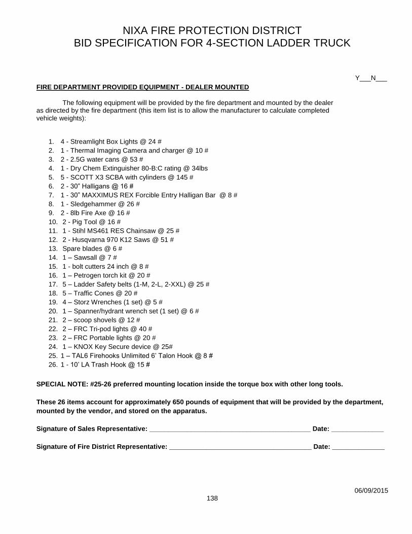
NIXA FIRE PROTECTION DISTRICT BID SPECIFICATION FOR 4-SECTION LADDER TRUCK
06/09/2015
138
Y___N___
FIRE DEPARTMENT PROVIDED EQUIPMENT - DEALER MOUNTED The following equipment will be provided by the fire department and mounted by the dealer as directed by the fire department (this item list is to allow the manufacturer to calculate completed vehicle weights):
1. 4 - Streamlight Box Lights @ 24 #
2. 1 - Thermal Imaging Camera and charger @ 10 #
3. 2 - 2.5G water cans @ 53 #
4. 1 - Dry Chem Extinguisher 80-B:C rating @ 34lbs
5. 5 - SCOTT X3 SCBA with cylinders @ 145 #
6. 2 - 30” Halligans @ 16 #
7. 1 - 30” MAXXIMUS REX Forcible Entry Halligan Bar @ 8 #
8. 1 - Sledgehammer @ 26 #
9. 2 - 8lb Fire Axe @ 16 #
10. 2 - Pig Tool @ 16 #
11. 1 - Stihl MS461 RES Chainsaw @ 25 #
12. 2 - Husqvarna 970 K12 Saws @ 51 #
13. Spare blades @ 6 #
14. 1 – Sawsall @ 7 #
15. 1 - bolt cutters 24 inch @ 8 #
16. 1 – Petrogen torch kit @ 20 #
17. 5 – Ladder Safety belts (1-M, 2-L, 2-XXL) @ 25 #
18. 5 – Traffic Cones @ 20 #
19. 4 – Storz Wrenches (1 set) @ 5 #
20. 1 – Spanner/hydrant wrench set (1 set) @ 6 #
21. 2 – scoop shovels @ 12 #
22. 2 – FRC Tri-pod lights @ 40 #
23. 2 – FRC Portable lights @ 20 #
24. 1 – KNOX Key Secure device @ 25#
25. 1 – TAL6 Firehooks Unlimited 6’ Talon Hook @ 8 #
26. 1 - 10’ LA Trash Hook @ 15 #
SPECIAL NOTE: #25-26 preferred mounting location inside the torque box with other long tools.
These 26 items account for approximately 650 pounds of equipment that will be provided by the department,
mounted by the vendor, and stored on the apparatus.
Signature of Sales Representative: ___________________________________________ Date: ______________
Signature of Fire District Representative: ______________________________________ Date: ______________

NIXA FIRE PROTECTION DISTRICT BID SPECIFICATION FOR 4-SECTION LADDER TRUCK
06/09/2015
139
Y___N___
LOOSE EQUIPMENT The following items will be provided by the fire department to be installed by the department onto the completed apparatus at the time of delivery (this item list is to allow the manufacturer to calculate completed vehicle weights):
1. 1 - Large Area Search bag @ 25 # 2. 1 – RIT Bag @ 25 # 3. 11 – Spare SCBA cylinders @ 165 # 4. 6 - 2 x 4 wedges @ 12 # 5. 6 – 4 x 4 cribbing @ 24 # 6. 4 – Wooden Step Chocks @ 44 # 7. 2 – Electric Fans @ 160 # 8. 2 – Jack Style door bar w/ hangers @ 12 # 9. 6 – Salvage Covers 12x18 @ 40 # 10. 1 - Flue Bucket w/ bombs @ 10 # 11. 1 – Ash Bucket w/ chain @ 25 # 12. 1 – Saw Box @ 6 # 13. 1 – Tool Box @ 30 # 14. 2 – Through the lock tool @ 2 # 15. 1 – S & D Rex Tool @ 3 # 16. 1 – Medical Bag @ 25 # 17. 1 – AED @ 10 # 18. 1 – SMR Bag @ 5 # 19. 5 – 30 minute road flares 20. 1 – 50’ Section of 5” LDH @ 50 # 21. 2 – 150’ Utility Ropes
These 21 items account for approximately 700 pounds of equipment that will be provided by the department
and stored on the apparatus.
Signature of Sales Representative: ___________________________________________ Date: ______________
Signature of Fire District Representative: ______________________________________ Date: ______________

NIXA FIRE PROTECTION DISTRICT BID SPECIFICATION FOR 4-SECTION LADDER TRUCK
06/09/2015
140
OPTIONAL PRICING The following items are to be bid individually as options to the base bid price: OPTION #1 Y___N___ DRIVELINE RETARDER (IN PLACE OF SPECIFIED ENGINE COMPRESSION BRAKE) A Telma electromagnetic, air cooled driveline retarder will be furnished installed within the driveline of the apparatus. The retarder will be independently mounted to the chassis frame rails and positioned to provide proper driveline angles and ease in maintenance one the driveline. The retarder will be sized to the maximum G.V.W.R. of the vehicle. The system will have an on/off switch and an indicator light on the dash. The retarder will automatically disengage when the vehicle is not in motion. Activation of the retarder will illuminate the vehicle brakes lights. The Telma retarder will be equipped with an electronic interface to de-activate the retarder anytime the ABS system is activated.
The magnetic retarder control will be controlled with an on/off switch on the dash and will be activated in conjunction with the brake pedal. The application will be in progressive stages, (1/4, 1/2, 3/4 & full).
The magnetic retarder control will be controlled with a five (5) position joystick control mounted on the dash panel. This joystick will allow for manual activation of the retarder when the throttle is released. The retarder application will be in four (4) progressive stages, (1/4, 1/2, 3/4 & full) as the joystick control is moved downward.
OPTION #2: Y___N___ TRI-MAX 20 COMPRESSED AIR FOAM SYSTEM
One (1) TRI-MAX 20 CAF system will be provided and installed on an existing roll-out tray as
directed by the Fire Department.
The TRI-MAX 20 CAF system will have the following features:
An external fire hose attachment
Outside Hose lay to fight external fires
Quick bolt on Installation for Emergency Vehicles
Wrap around frame
External Discharge hose
Pistol-grip nozzle
Specifications:
Height: 48.75″ Width: 20″ Depth: 25 1/4″
Loaded Weight: 400 lbs. Empty Weight: 240 lbs.
Premix Tank: 20-gallon capacity
Finished Foam Capacity: Approximately 400 gallons
Discharge Nozzle: 1” standard or pistol grip style

NIXA FIRE PROTECTION DISTRICT BID SPECIFICATION FOR 4-SECTION LADDER TRUCK
06/09/2015
141
Discharge Rate (max): 300 gal/minute of finished foam
Foam Discharge Distance: approx. 65-75 feet in a zero-wind condition
Air Cylinder (Scuba): Two (2) 50 cu. ft. 3000 psi
Regulator: Adjustable pressure 0-400 psi
Dispensing Hose: 50 feet of 1” collapsible hose
Usable Hose Length: 500 plus feet
The CAF system will be mounted on a dedicated 500# Floor mounted roll-out tray. The tray
will consist of heavy duty, roller bearing slide tracks with a load rating of 500 pounds,
securely fastened to the compartment floor. The tray will be fabricated from 3/16" brushed
aluminum with a minimum 2" high flange on each of the four sides to assist in retaining the
equipment stored on each tray. The slide tracks will have a 100% extension, allowing the tray
to extend out of the compartment completely.
OPTION #3: Y___N___ Engine Enclosure Cover A brushed stainless steel or aluminum tread plate cover shall be mounted across the entire rear portion of the engine box. An engine box mounting plate shall be mounted on top of the engine cover for radio, hand light, and equipment mounting.
OPTION #4: Tire Pressure Monitoring System Y___N___
A Crossfire tire pressure monitoring system will be provided for the rear tandem axle tires.
http://inflationsolutions.com/truck-and-rv-products/crossfire-tire-pressure-system/
OPTION #5: Y___N___ Stainless Steel Fuel Tank A stainless steel fuel tank meeting the same requirements listed above will be provided.
OPTION #6: Y___N___ “SMART WHEEL” STEERING WHEEL or equivalent
NIXA FIRE PROTECTION DISTRICT BID SPECIFICATION FOR 4-SECTION LADDER TRUCK
06/09/2015
142
The steering column will be a "Smart Wheel" multiplexed steering wheel. The "Smart Wheel"
will be designed so that the driver's hands never need to leave the steering wheel once the engine is
running and the parking brake is released.
The "Smart Wheel" steering wheel will include ten (10) multiplexed switches that control the
following functions:
Air Horn
Q2B (If Equipped)
Q2B Brake (If Equipped)
Master Warning Switch
Mic (Push to talk)
Siren
Auxiliary Braking
High Idle
Throttle Up - High Idle Function
Throttle Down - High Idle Function
The functions will be multiplexed through a clock spring circuit board. Collector rings switch
wiring is not acceptable! The steering wheel will be 18 inches in diameter.
In addition to the Smart Wheel switches the electric horn switch will be located in the center of the steering wheel.
Related Documents