ATENCIÓN: Lea, entienda y siga las instrucciones de seguridad contenidas en este manual antes de operar esta herramienta. WARNING: Read, understand and follow the safety rules in this manual, before operating this tool. Nivel Láser de 1 Línea y Punto Line & Point Laser Level NL1 Manual de Usuario y Garantía. User’s Manual and Warranty.

Welcome message from author
This document is posted to help you gain knowledge. Please leave a comment to let me know what you think about it! Share it to your friends and learn new things together.
Transcript

ATENCIÓN: Lea, entienda y siga las instrucciones de seguridad contenidas en este manual antes de operar esta herramienta.WARNING: Read, understand and follow the safety rules in this manual, before operating this tool.
Nivel Láser de 1 Línea y PuntoLine & Point Laser Level
NL1Manual de Usuario y Garantía.
User’s Manual and Warranty.
NL1 manual.indd 1 07/03/17 12:10

2
E N G L I S H E S P A Ñ O L
General safety rules
Features
Operation instructions
Maintenance
Technical data
Notes
Warranty policy
Normas generales de seguridad
Características
Instrucciones de operación
Mantenimiento
Especificaciones técnicas
Notas
Garantía
7
7
8
9
10
11
12
3
3
4
6
6
11
12
CONTENIDO CONTENT
SÍMBOLOS SYMBOLS
PELIGRO, ADVERTENCIA, PRECAUCIÓN: Indica un riesgo personal o la posibilidad de un daño.
ADVERTENCIA, PRECAUCIÓN: Radiación lá-ser. Utilice equipo de seguridad adecuado.
DANGER, CAUTION, WARNING: Indicates risk of personal injury and/or the possibility of damage.
CAUTION, WARNING: Laser radiation. Use the adequate safety equipment.
NL1 manual.indd 2 07/03/17 12:10
3
E S P A Ñ O L • Manual de Usuario
NORMAS GENERALES DE SEGURIDADTodas las instrucciones deben de leerse y ob-servarse con el objetivo de trabajar de mane-ra segura con el aparato de medición. Nunca haga señas de seguridad no reconocibles en el aparato de medición. GUARDE ESTAS INS-TRUCCIONES PARA FUTURAS REFERENCIAS Y INCLÚYALAS CON LA HERRAMIENTA DE MEDI-CIÓN CUANDO SE LO DE A UN TERCERO.
PRECAUCIÓN: El uso de otra operación o ajustando el equipo o la aplicación de otro mé-todo de procesamiento que no sean los men-cionado aquí pueden conllevar exposición a radiación peligrosa.• La herramienta de medición viene con una etiqueta de ADVERTENCIA.• Si el texto de advertencia de la etiqueta no está en su lenguaje nacional, pegue la etiqueta provista en su lenguaje nacional antes de ope-rar por primera vez.
No dirija el rayo láser a personas o ani-males y no mire directamente o refleje el rayo láser hacia usted, no inclusive a distancia. Usted puede segar a alguien,
causar accidentes o dañar sus ojos.• Si la radiación del láser alcanza sus ojos usted debe deliberadamente cerrar sus ojos e inme-diatamente girar su cabeza a otra dirección.• No haga modificación alguna al equipo láser.• No use el láser utilizando lentes de visión láser como lentes de seguridad. Los lentes de visión láser son usados para mejorar la visuali-zación del rayo láser, pero no lo protegen de la radiación láser.• No use los lentes de visión láser como lentes de sol o en el tráfico. Los lentes de visión láser no le ofrecen una completa protección UV y re-ducen su percepción de los colores.• Tenga su herramienta de medición repara-da únicamente por especialistas calificados usando piezas originales. Esto asegura que la seguridad de la herramienta de medición sea mantenida.• No permita que los niños utilicen la herra-mienta de medición láser sin supervisión. Ellos podrían accidentalmente cegar otras personas o a si mismos.• No opere la herramienta de medición en am-bientes explosivos, tales como en la presencia
de liquidos flamables, gases o polvos. Se pue-den crear chispas dentro de la herramienta de medición que podría encender polvos o gases.
CARACTERÍSTICAS
USO INTENCIONADOLa herramienta está intencionada para deter-minar e indicar líneas horizontales y verticales exactas. Esto es conveniente para revisar líneas de desagüe y particiones horizontales o super-ficies.La herramienta es conveniente exclusivamen-te para operación en sitios de trabajo interior cerrados.
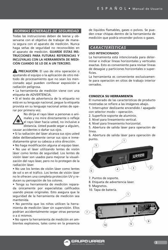
CONOZCA SU HERRAMIENTAEl numerado de las características de producto mostradas se refiere a las imágenes abajo.1. Interruptor deslizante encendido / apagado con selector modo – operación.2. Superficie soporte de aluminio.3. Nivel para lineamiento vertical.4. Nivel para lineamiento horizontal.5. Abertura de salida láser para operación de línea.6. Abertura de salida láser para operación de punto.
7. Puntos de soporte.8. Etiqueta de advertencia láser.9. Magnetos.10. Tapa de batería.
1
236
4
5
1
810 9
7
NL1 manual.indd 3 07/03/17 12:10

4
11. Gafas de visión láser*12. Tripié*13. Sujetador de muro.14. Superficie metálica para operación en línea.15. Superficie de metal para operación de punto.16. Tornillo de ajuste para sujetador de muro.17. Montura tripié de ¼” para sujetador de muro.
*Los accesorios ilustrados o descritos no están incluidos como entrega estándar
INSTRUCCIONES DE OPERACIÓN
IMPORTANTE: El rango de trabajo puede ser disminuido por condiciones ambientales desfavorables (por ejemplo, radiación solar di-recta).
ENSAMBLEInsertando/Reemplazando las baterías.NOTA: Se recomienda utilizar pilas alcalinas de manganeso para la herramienta de medición.Para abrir la tapa de las baterías, deslice en la dirección de la flecha fuera del compartimen-to de las baterías. Inserte las baterías provistas. Cuando las inserte ponga atención a la polari-dad correcta acorde a la representación en el interior del compartimento de baterías.Siempre cambie todas las pilas al mismo tiem-po. Utilice baterías de una sola marca y con la misma capacidad.Retire las baterías de la herramienta de me-dición cuando no se vaya a utilizar durante períodos prolongados. Cuando se almacena durante períodos prolongados, las baterías pueden corroerse y descargarse.
OPERACIÓN INICIALProteja el aparato de medición contra la hume-dad y luz directa del sol.• No exponga el aparato de medición a tempe-raturas extremas o variaciones de temperatura. Por ejemplo, no lo deje en vehículos por perío-dos largos. En caso de grandes variaciones de temperatura, permita que la herramienta de medición se ajuste a la temperatura ambiente antes de ponerlo en funcionamiento.• Evitar impactos pesados o dejar caer la herra-mienta de medición. Daños en el aparato de medición pueden afectar su precisión. • Apague la herramienta de medición durante el transporte. Cuando se apaga, la unidad ni-veladora se bloquea ya que puede dañarse en algún movimiento fuerte.
ENCENDIDO Y APAGADOPara encender la herramienta de medición en modo de operación “línea”, presione el inte-rruptor de encendido/apagado 1 hacia adelan-te. Para cambiar la herramienta de medición a modo “punto”, presione el interruptor 1 hacia atrás.Inmediatamente después de encenderse, la herramienta de medición envía un rayo láser fuera de la apertura 5 (modo línea) o 6 (modo punto), dependiendo del modo de operación seleccionado.No apunte el láser a personas o animales y no mire el haz láser, no incluso desde una gran distancia.Para Apagar la herramienta de medición, pre-sione el interruptor 1 a la posición del centro.· No deje la herramienta encendida sin aten-ción y apáguela después de su uso. Otras perso-nas pueden cegarse por el rayo láser.
FUNCIONES DE NIVELADONOTA: La precisión del nivelado será reflejado cuando se coloque el nivel de manera correc-ta alineando los niveles de burbuja dentro del alma de las marcas.Si escapa el líquido del nivel de burbuja, quí-telo con un material absorbente adecuado y tírelo de forma segura. El líquido del nivel contiene liquidos flamables que pueden causar irritación en las vías respiratorias, ojos y piel.
15
13
1417
16
NL1 manual.indd 4 07/03/17 12:10

5
E S P A Ñ O L • Manual de Usuario
OPERACIÓNPosición de la herramienta (Vea figura B)Para lineamiento preciso con el nivel, es impor-tante la posición de la herramienta.La precisión de nivelado especificada se obtie-ne solo cuando la herramienta está correcta-mente posicionada.Para lineamiento horizontal, la salida del laser para operación de línea debe estar horizontal y la base de soporte de aluminio de la herra-mienta de medición debe estar hacia abajo.Para lineamiento vertical, la salida del laser para operación de línea debe estar hacia arriba y el base de soporte de aluminio de la herra-mienta de medición debe estar hacia un lado.
Alineando con línea laser (operación de línea)Coloque el aparato de medición con su soporte de pared (13), contra la pared a través de los tres puntos de apoyo (7) o fijarlo a una superfi-cie magnética con los imanes (9).
Alineación horizontal (ver figuras C, D) la abertura de salida laser para operación de línea 5 debe ser horizontal y el soporte de alu-minio 2 de la herramienta de medición debe mirar hacia abajo. Alinee horizontalmente el aparato de medición con nivel 4. Por ejemplo, puede alinear marcos de cuadros o estantes junto a la línea láser horizontal.NOTA: La alineación Horizontal con la línea de láser sólo es posible en la superficie, contra el cual se colocó el aparato de medición. Incluso cuando el aparato de medición fue alineado con el nivel de burbuja, la línea de láser en una pared transversal no necesariamente funciona horizontal y no es así conveniente para nivelar.
Alineación vertical (ver figura D) La salida de láser para operación de línea 5 debe quedar hacia arriba y el apoyo a través 2 de la herramienta de medición de aluminio debe estar hacia un lado. Alinee verticalmen-te la herramienta de medición con nivel 3. Por ejemplo, puede alinear gabinetes base y supe-rior junto a la línea de láser vertical.
Alineación de referencia puntos (ver figura E) Gire el aparato de medición a cualquier ángulo requerido para alinear la línea de láser junto con sus puntos de referencia. Por ejemplo, esto puede usarse para colgar Marcos paralelos a escaleras o a la inclinación de un techo.
Proyección / chequeo de alturas vía punto lá-ser (operación de punto) (ver figura F) Coloque la herramienta de medición en el so-porte de pared y alinearlo horizontalmente. Por ejemplo, puede utilizar el punto del láser para alinear tomas en diferentes paredes o colgar de ganchos de guardarropa a la misma altura. Para ello, gire la parte superior del so-porte de pared 13 con la herramienta de medi-ción y no el aparato de medición en el soporte de pared.
Fig. B
Fig. C
Fig. D
Fig. E
Fig. F
NL1 manual.indd 5 07/03/17 12:10

6
Al girar, preste atención a no tocar la herra-mienta de medición, caso contrario que podría cambiar su posición.• Trabajar con trípode (recomendado): Alinee el rayo láser a la altura requerida.Proyecto o consultar la altura en la ubicación de destino.• Trabajar sin tripié: Determine la diferencia de altura entre el rayo láser y la altura del punto de referencia. Proyecte o compruebe la dife-rencia de altura medida en el lugar de destino.
Chequeo Horizontal / Vertical líneas con los ni-veles láser (ver figura G)El aparato de medición puede también utili-zarse como un nivel de carpintero para la com-probación de líneas verticales y horizontales, por ejemplo, para alinear una lavadora o un refrigerador. Coloque el aparato de medición con la superficie de aluminio de apoyo 2 sobre la superficie a verificar. Al colocar en superfi-cies horizontales, la superficie de apoyo 2 debe mirar hacia abajo, al poner contra superficies verticales, de aluminio debe hacia arriba la sa-lida láser para operación de la línea 5.
ADVERTENCIAS DE TRABAJOPara el marcado, siempre utilice sólo el centro del punto láser o la línea de láser. El tamaño de punto láser así como el ancho de la línea cambia con la distancia.
Fijación/alineación con el soporte de paredCon el soporte de pared 13, el aparato de me-dición puede fijarse como sigue: Línea de operación: Coloque el soporte de pared a través de su nicho en la parte trasera sobre una cabeza de tornillo ligeramente sa-liente de una pared. Sujetar el aparato de me-dición con los imanes 9 a la superficie del metal para la operación de la línea 14 del soporte de pared.Girar la parte superior del soporte de pared para alinear el aparato de medición según se requiera.
RANGO DE TRABAJO
PRECISIÓN DEL LÁSER
TIPO DE LÁSER
BATERÍAS
TIEMPO DE TRABAJO
PESO
Linea: 3 m • Punto: 20 m
Linea: ±1 mm/m
Punto: ±0.5 mm/m
Clase 2, <1mW
2 x 1,5 V (AAA)
>15 h
159 g
ESPECIFICACIONES TÉCNICAS
Funcionamiento de punto: el soporte de pared mediante el trípode 17 el 1/4" rosca de trípode de montaje y apriete el tornillo de fijación del trípode. Alinee el trípode más o menos.Al trabajar sin trípode, coloque el soporte de pared en una superficie lo más horizontal po-sible. Coloque el aparato de medición con el aluminio soporte revestimiento de superficie 2 abajo en el soporte de pared. Fije mediante el imán izquierdo 9 (visto desde la parte frontal de la herramienta de medición) a la superficie del metal para la operación del punto 15 del soporte de pared.Horizontal alinear la parte superior del soporte de pared con tornillo de ajuste 16 del nivel 4 de la herramienta de medición y soporte de pa-red. Gire la parte superior del soporte de pared de 90' y repita la alineación.
MANTENIMIENTO• Mantenga el aparato de medición limpio en todo momento.• No sumerja el aparato de medición en agua u otros líquidos.• Limpie la suciedad con un paño húmedo y suave. No use cualquier producto de limpieza o disolventes.• Periódicamente Limpie las superficies en la abertura de salida del láser en particular y pres-tar atención a cualquier pelusa de fibras.
ELIMINACIÓN DE DESECHOSLas herramientas de medición, los accesorios y los envases deben clasificarse para un reciclaje ecológico. ¡No deseche las herramientas de medición en la basura doméstica!
PILAS Y BATERÍASNo deseche las baterías en la basura doméstica, el fuego o el agua. Los paquetes de baterías / pilas deben recolectarse, reciclarse o desecharse de manera respetuosa con el medio ambiente.
Fig. G
NL1 manual.indd 6 07/03/17 12:10

7
E N G L I S H • User’s manual
GENERAL SAFETY RULESSafety NotesWorking safely with the measuring tool is pos-sible only when the operating and safety in-formation are read completely and the instruc-tions contained therein are strictly followed. Never make warning labels on the measuring tool unrecognizable. SAVE THESE INSTRUC-TIONS.
CAUTION: The use of other operating or adjusting equipment or the application of other processing methods than those men-tioned here, can lead to dangerous radiation exposure.
Do not direct the laser beam at persons or animals and do not stare into the la-ser beam yourself. This measuring tool produces laser class 2 laser radiation ac-
cording to IEC 60825-1. This can lead to persons being blinded.• Do not use the laser viewing glasses as safety goggles. The laser viewing glasses are used for improved visualization of the laser beam, but they do not protect against laser radiation.• Do not use the laser viewing glasses as sun glasses or in traffic. The laser viewing glasses do not afford complete UV protection and re-duce color perception.• Have the measuring tool repaired only through qualified specialists using original spare parts. This ensures that the safety of the measuring tool is maintained.• Do not allow children to use the laser mea-suring tool with- out supervision. They could unintentionally blind other persons or them-selves.• Do not operate the measuring tool in explo-sive environments, such as in the presence of flammable liquids, gases or dusts. Sparks can be created in the measuring tool which may ignite the dust or fumes.+ Keep the measuring tool away from cardiac pacemakers. The magnets 7 generate a field that can impair the function of cardiac pace-makers.+ Keep the measuring tool away from mag-netic data medium and magnetically-sensitive equipment. The effect of the magnets 7 can lead to irreversible data loss.
FEATURESINTENDED USEThe tool is intended for determining and in-dicating exact horizontal and vertical lines. It is also suitable for checking plumb lines and horizontal partitions or surfaces.The tool is suitable exclusively for operation in enclosed/ interior working sites.
KNOW YOUR TOOLThe numbering of the product features shown refers to the illustration of the measuring tool on the graphic page.1. On / Off slide switch with operating-mode selector.2. Aluminium supporting surface.3. Spirit level for vertical alignment.4. Spirit level for horizontal alignment.5. Laser outlet opening for line operation.6. Laser outlet opening for point operation.
7. Supporting points.8. Laser warning label.9. Magnets.10. Battery lid.
11. Laser viewing glasses*.12. Tripod*.13. Wall holder.14. Metal surface for line operation.15. Metal surface for point operation.16. Adjusting screw of wall holder.17. ¼’’ Tripod mount of wall holder.
1
236
4
5
1
810 9
7
NL1 manual.indd 7 07/03/17 12:10

8
* The accessories illustrated or described are not included as standard delivery.
OPERATION INSTRUCTIONS
IMPORTANT: The working range can be decreased by unfavorable environmental con-ditions (e.g. direct sun radiation).Please observe the article number on the type plate of your measuring tool. The trade names of the individual measuring tools may vary.
ASSEMBLYInserting/Replacing the BatteryNOTE: Alkali-manganese batteries are recom-mended for the measuring tool.To open the battery lid 10 ,slide it in the direc-tion of the arrow away from the battery com-partment. Insert the batteries provided. When inserting,pay attention to the correct polarity according to the representation on the inside of the battery compartment.Always replace all batteries at the same time. Only use batteries from one brand and with the identical capacity.Remove the batteries from the measuring tool when not using it for extended periods. When storing for extended periods, the batteries can corrode and discharge themselves.
INITIAL OPERATIONProtect the measuring tool against moisture and direct sun light.• Do not subject the measuring tool to extreme temperatures or variations in temperature. As an example, do not leave it in vehicles for lon-ger periods. In case of large variations in tem-perature, allow the measuring tool to adjust
to the ambient temperature before putting it into operation.• Avoid heavy impact to or falling down of the measuring tool. Damage to the measuring tool can impair its accuracy. After heavy impact or falling down, check the angle accuracy be-tween the 0° and 90° laser line with the angle of a precision square.
SWITCHING ON AND OFFTo switch on the measuring tool in line op-eration, push the On/Off switch 1 forward . To switch on the measuring tool in point opera-tion, push the On/Off switch 1 back.Immediately after switching on, the measuring tool sends a laser beam out of outlet opening 5 (line operation) or 6 (point operation), de-pending on the selected operating mode.· Do not point the laser beam at persons or animals and do not look into the laser beam yourself, not even from a large distance.To switch off the measuring tool, push the on/off switch 1 to the center position.· Do not leave the switched on tool unattended and switch the tool off after use. Other persons could be blinded by the laser beam.When not using the measuring tool,switch it off in order to extend the battery life.
LEVELING FUNCTIONNOTE: The specified leveling accuracy applies for the alignment of the laser beam with refer-ence to the spirit levels 3 and 4.If spirit level leaks, soak up with appropriate absorbent material and dispose of safely. Spirit levels contain flammable liquid that may cause respiratory tract, eye and skin irritation.
OPERATIONPosition the Tool (see figure B)For precise alignment with the spirit levels, the position of the- tool is important.
The specified leveling accuracy is only achieved when the tool is correctly positioned:For horizontal alignment with spirit level 4, the laser outlet opening for line operation 5 must be horizontal and the aluminium supporting surface 2 of the measuring tool must face downward. For vertical alignment with spirit
15
13
1417
16
NL1 manual.indd 8 07/03/17 12:10

9
E N G L I S H • User’s manual
level 3, the laser outlet opening for line opera-tion 5 must face upward and the aluminium supporting surface 2 of the measuring tool must face sideward.
Alignment with Laser Line (Line Operation)Fasten the measuring tool to wall holder 13, place it against a wall via the three support-ing points 7 or fasten it to an other magnetic surface with the magnets 9.
Horizontal Alignment (see figures C-D)The laser outlet opening for line operation 5 must be horizontal and the aluminum support-ing surface 2 of the measuring tool must face downward. Horizontally align the measuring tool with spirit level 4. As an example, you can align picture frames or shelves alongside the horizontal laser line.NOTE: Horizontal alignment with the laser line is only possible on the surface, against which the measuring tool was placed. Even when the measuring tool was aligned with the spirit level, the laser line on a transverse wall does not necessarily run horizontal, and is thus not suitable for leveling.
Vertical Alignment (see figure D)The laser outlet opening for line operation 5 must face upward and the aluminium sup-porting surface 2 of the measuring tool must face sideward. Vertically align the measuring tool with spirit level 3. As an example, you can align top and base cabinets alongside the verti-cal laser line.
Alignment off of reference points (see fig E)Turn the measuring tool to any required angle in order to align the laser line alongside your reference points. As an example, this can be used to hang picture frames parallel to stairs or to the incline of a roof.
Projecting/Checking Heights via Laser point (point operation) (see figure F)Place the measuring tool on the wall holder and horizontally align it. As an example, you can use the laser point to align socket outlets on different walls or hang up wardrobe hooks at the same height. For this, turn the upper part of the wall holder 13 with the measuring tool, and not the mea-suring tool on the wall holder.
When turning, pay attention not to touch the measuring tool, otherwise its position could be changed.• Working with tripod (recommended): Align the laser beam to the requested height.Project or check the height at the target loca-tion.• Working without tripod: Determine the height difference between the laser beam and
Fig. B
Fig. C
Fig. D
Fig. E
Fig. F
NL1 manual.indd 9 07/03/17 12:10

10
the height art the reference point. Project or check the measured height difference at the target location.
Checking Horizontal / Vertical Lines with the Spirit Levels (see figure G)The measuring tool can also be used as a car-penter’s spirit level for checking vertical and horizontal lines, for example to align a wash-ing machine or a refrigerator. Position the measuring tool with the aluminium supporting surface 2 on the surface to be checked. When placing on horizontal surfaces, the aluminium supporting surface 2 must face downward, when placing against vertical surfaces, the laser outlet opening for line operation 5 must face upward.
WORKING ADVICEFor marking, always use only the centre of the laser point or the laser line. The size of the laser point as well as the width of the laser line change with distance.
Fastening/aligning with the wall holderWith the wall holder 13, the measuring tool can be fastened as follows:Line operation: Place the wall holder via its re-cess on the backside onto a screw head slightly projecting out of a wall. Fasten the measuring tool with the magnets 9 to the metal surface for line operation 14 of the wall holder.Turn the upper part of the wall holder to align the measuring tool as required.Point operation: Place the wall holder via the tripod mount 17 onto the 1/4” male thread of the tripod and screw the locking screw of the tripod tight. Align the tripod roughly.When working without tripod, place the wall holder on a surface that is as horizontal as pos-sible.Position the measuring tool with the alu-minium supporting surface 2 facing down on the wall holder. Attach it via the left magnet
TECHNICAL DATAWORKING RANGE
LASER ACCURACY
LASER POWER
BATTERIES
WORKING OPERATION
WEIGHT
Line: 3 m • Point: 20 m
Line: ±1 mm/m
Point: ±0.5 mm/m
Class 2, <1mW
2 x 1,5 V (AAA)
>15 h
159 g
Fig. G
9(viewed from the front side of the measuring tool) to the metal surface for point operation 15 of the wall holder.Horizontal align the upper part of the wall holder with adjusting screw 16 of the wall holder and spirit level 4 of the measuring tool. Turn the upper part of the wall holder by 90` and repeat the alignment.
MAINTENANCE• Keep the measuring tool clean at all times.• Do not immerse the measuring tool in water or other fluids.• Wipe off debris using a moist and soft cloth. • Do not use any cleaning agents or solvents.• Regularly clean the surfaces at the exit open-ing of the laser in particular, and pay attention to any fluff of fibres.
DISPOSALMeasuring tools, accessories and packaging should be sorted for environmental-friendly recycling.Do not dispose of measuring tools into house-hold waste! According the European Guideline 2002/96/EC for Waste Electrical and Electronic Equipment and its implementation into na-tional right, measuring tools that are no lon-ger usable must be collected separately and disposed of in an environmentally correct manner.
BATTERY PACKS/BATTERIES:Do not dispose of battery packs/batteries into household waste, fire or water. Battery packs/batteries should be collected, recycled or dis-posed of in an environmental-friendly manner.
NL1 manual.indd 10 07/03/17 12:10

11
Manual de usuar io / User ’s manua l
Notas / Notes
NL1 manual.indd 11 07/03/17 12:10

12
NL1
E S P A Ñ O LPÓLIZA DE GARANTÍA
E N G L I S HWARRANT POLICY
Urrea Herramientas Profesionales S.A. de C.V. Warranties this product for a period of 1 year in its parts, components and manual labour against any manufacture defect from the purchasing date.
Purchase date: ____/____/____Product:____________________Brand:______________________Model:______________________
______________________________Distributor seal and signature
Sold and Imported by:Urrea Herramientas Profesionales S.A. de C.V. km 11,5 Carretera A El Castillo, El Salto, Jalis-co, México. C. P. 45680, Tel. (33) 3208 7900, RFC UHP900402Q29
Terms:In order to make warranty effective you must pres-ent the product along with the warranty properly fillled and signed to an authorized distributor or service center.
Urrea Herramientas Profesionales S.A. de C.V. will cover the transportation cost related to the warranty.
This warranty is not applicable in the follow-ing cases:· When the product has not been used according to normal conditions or natural wear of its parts. · When the product has not been used according with this user’s manual instructions. · When the product has been fixed or modified by unauthorized or unqualified person.
Urrea Herramientas Profesionales S.A. de C.V. garantiza este producto por el termino de 1 año en sus piezas, componentes y mano de obra con-tra cualquier defecto de fabricación a partir de la fecha de entrega.
Fecha de venta: ____/____/____Producto: ___________________Marca: ______________________Modelo: ____________________
______________________________Sello y firma de distribuidor
Comercializado e Importado por:Urrea Herramientas Profesionales S.A. de C.V. km 11,5 Carretera A El Castillo, El Salto, Ja-lisco, México. C. P. 45680, Tel. (33) 3208 7900, RFC UHP900402Q29
Condiciones:Para hacer efectiva la garantía deberá presentar el producto junto con la póliza de garantía debi-damente firmada y sellada por el establecimiento donde la adquirió, en cualquiera de los centros de servicio autorizados. Los gastos de transportación que se deriven del cumplimiento de la garantía serán cubiertos por:Urrea Herramientas Profesionales S.A. de C.V.
Esta garantía no será valida en los siguientes casos:· Cuando el producto haya sido utilizado en condi-ciones distintas a las normales o al desgaste natu-ral de sus partes. · Cuando el producto no haya sido operado de acuerdo al instructivo de uso que lo acompaña. · Cuando el producto haya sido alterado o repara-do por personas no autorizadas.
NL1 manual.indd 12 07/03/17 12:10
Related Documents