Welcome message from author
This document is posted to help you gain knowledge. Please leave a comment to let me know what you think about it! Share it to your friends and learn new things together.
Transcript
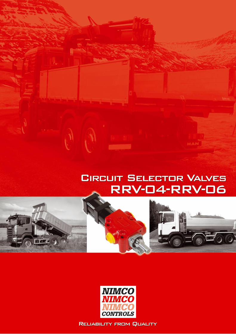
RRV-04 - RRV-06Circuit Selector Valves
2
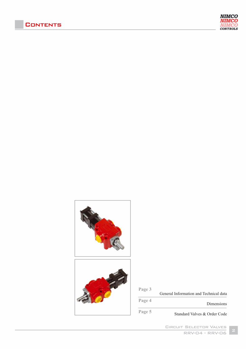
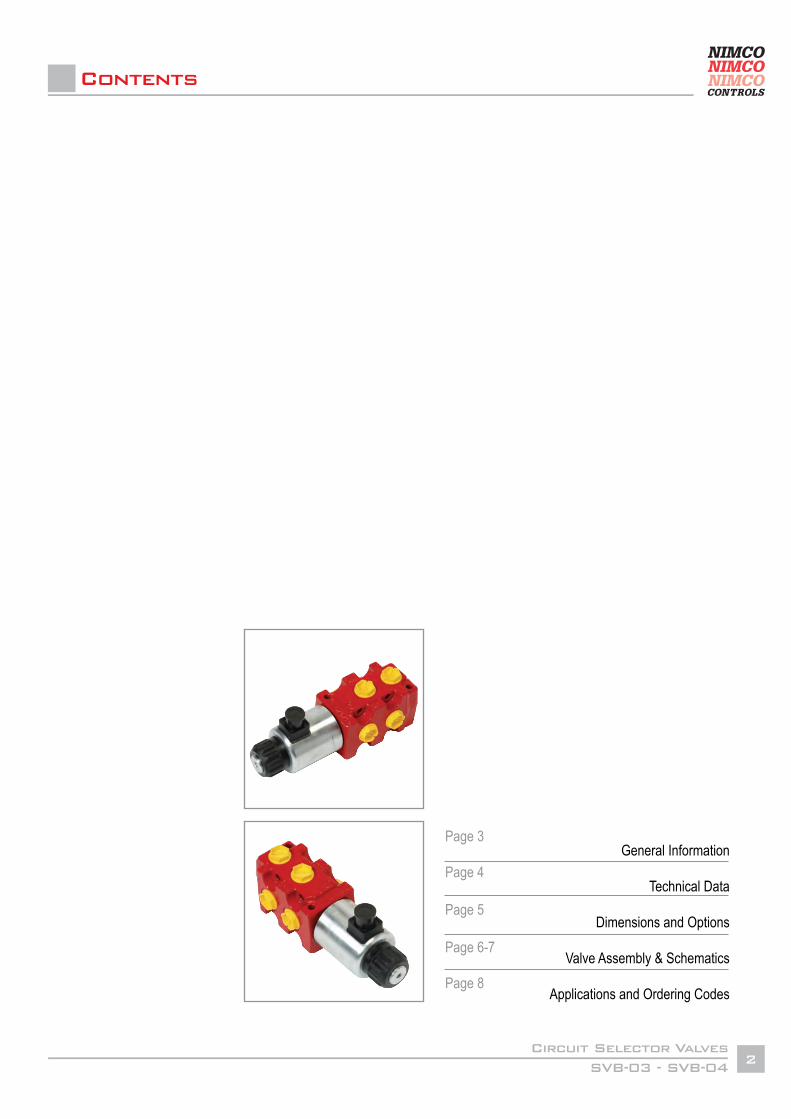
Contents
General Information and Technical data
Dimensions
Standard Valves & Order Code
Page 3
Page 4
Page 5
RRV-04 - RRV-06Circuit Selector Valves
3
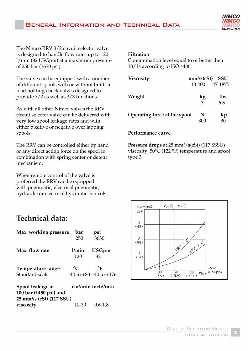
General Information and Technical Data
RRV-04 - RRV-06Circuit Selector Valves
4
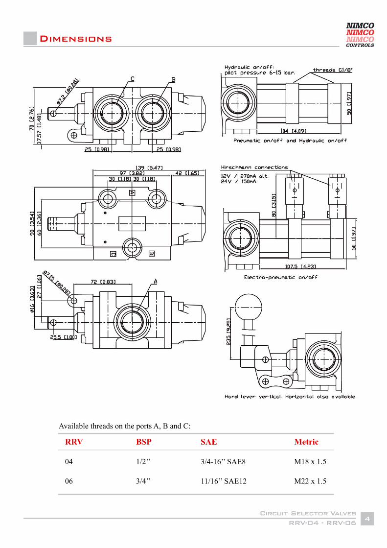
Dimensions
RRV
04
06
BSP
1/2’’
3/4’’
SAE
3/4-16’’ SAE8
11/16’’ SAE12
Metric
M18 x 1.5 M22 x 1.5
Available threads on the ports A, B and C:
RRV-04 - RRV-06Circuit Selector Valves
5
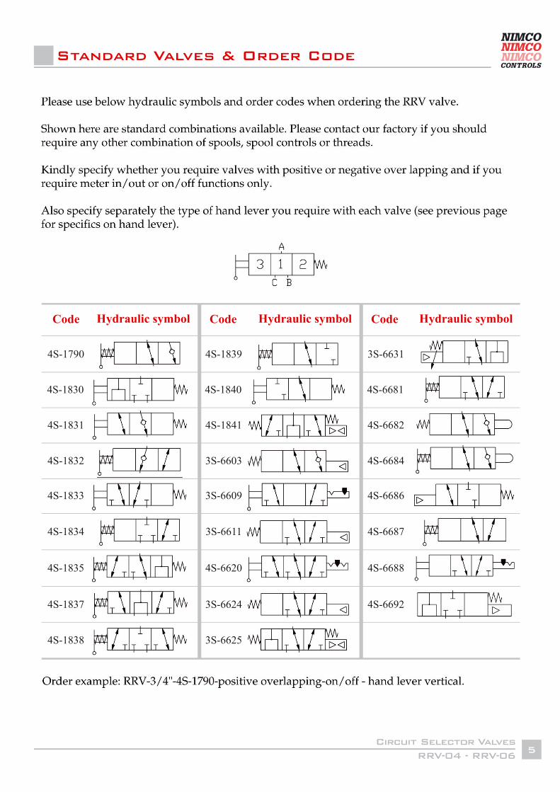
Standard Valves & Order Code
Code
4S-1790
4S-1830
4S-1831
4S-1832
4S-1833
4S-1834
4S-1835
4S-1837
4S-1838
4S-1839
4S-1840
4S-1841
3S-6603
3S-6609
3S-6611
4S-6620
3S-6624
3S-6625
3S-6631
4S-6681
4S-6682
4S-6684
4S-6686
4S-6687
4S-6688
4S-6692
Hydraulic symbol Code Code Hydraulic symbol Hydraulic symbol
SVB-03 - SVB-04Circuit Selector Valves
2
Contents
General Information
Technical Data
Dimensions and Options
Valve Assembly & Schematics
Applications and Ordering Codes
Page 3
Page 4
Page 5 Page 6-7 Page 8
SVB-03 - SVB-04Circuit Selector Valves
3
General Information
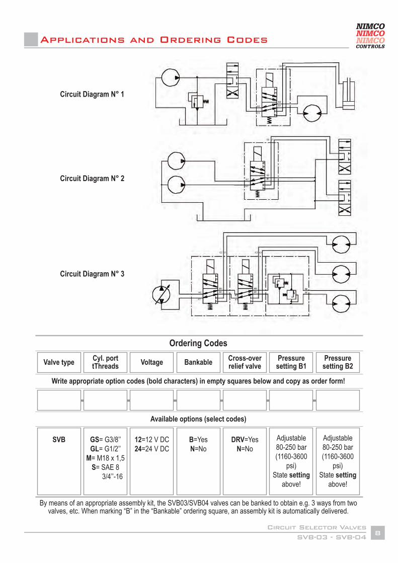
The SVB 03 and SVB 04 stackable 6 port/2 way circuit selector valves are designed to be used when extra circuits are to be operated from one control lever on machines such as fork lift trucks, agricultural front end loader, telescopic handlers, and in transmission circuits.
Up tp 3 SVB valves can be stacked up allowing for the diverting of flow into 2, 3 or 4 directions depending on the combination chosen.
NIMCO’s SVB 03 and SVB 04 circuit selector valves have been carefully designed to meet the demands of progressive machine manufacturers for cost effective, reliable circuit selectors. The valve bodies are made from a special high quality cast iron alloy which is machined, using NIMCO’s advanced machining techniques, to precise tolerances, ensuring, along with the other component parts, the consistency of the finished product.
They are designed for a max. working pressure of 280 bar (4060 psi) and will accept flows up to 90 l/min (23.8 USgpm) - 1/2’’ ported version. The advanced design of the valve spool ensures that fast spool switching can take place under any conditions without the use of a seperate drain line.
The NIMCO circuit selector valves are often connected to the service ports of a double acting spool valve, to allow two double acting services to be operated from the one service (see circuit 1 on page 7).
The SVB valves can also be used to benefit circuits where the spool valves are located a long distance from the pumps. In this case the de-energized SVB valve will return both lines to tank and, when energized, feed the circuit spool valves. This provides the advantage of minimizing the pressure drop through the system when needed, such as when transporting a machine in non-operational mode (see circuit 2 on page 7).
A third possibility is to use one (or two) SVB valves in a closed type hydrostatic system where one pump drives two (or three) different motors. In this instance the SVB valve will replace two (or three) directional control valves (see circuit 3 on page 7).
The valve is actuated from one position to the other by a constant-rated wet pin type solenoid. Solenoid operation of the valve allows it to be controlled from a switch located in a control lever handle. This allows an operator to activate an SVB selector valve quickly as part of sequence of machine operations, such as on an agricultural tractor loader switching from bucket tilt to a grab or rotator unit.
The NIMCO SVB valve’s constant-rated wet pin solenoid is capable of switching from one circuit to another at the rated flow and pressure.
The SVB valve bank can be optionally equipped with a flangeable housing, containing a dual cross-over relief valve, on the outlet end of the valve, thereby protecting the motor or cylinder operated by the B ports of the last downstream valve section against excessive pressure.
SVB-03 - SVB-04Circuit Selector Valves
4
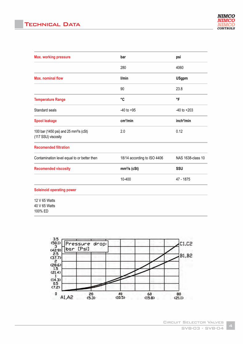
Technical Data
Max. working pressure
Max. nominal flow
Temperature Range
Standard seals
Spool leakage
100 bar (1450 psi) and 25 mm²/s (cSt) (117 SSU) viscosity
Recomended filtration
Contamination level equal to or better then Recomended viscosity
Soleinoid operating power
12 V 65 Watts40 V 65 Watts100% ED
bar
280
l/min
90
°C
-40 to +95
cm³/min
2.0
18/14 according to ISO 4406
mm²/s (cSt)
10-400
psi
4060
USgpm
23.8
°F
-40 to +203
inch³/min
0.12
NAS 1638-class 10
SSU
47 - 1875
SVB-03 - SVB-04Circuit Selector Valves
5
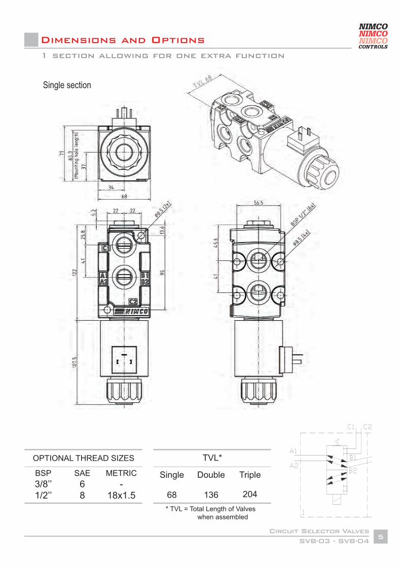
Dimensions and Options
Single section
* TVL = Total Length of Valves when assembled
TVL*
Single
68
Double
136
Triple
204
OPTIONAL THREAD SIZES
BSP3/8’’1/2’’
SAE68
METRIC-
18x1.5
1 section allowing for one extra function
SVB-03 - SVB-04Circuit Selector Valves
6
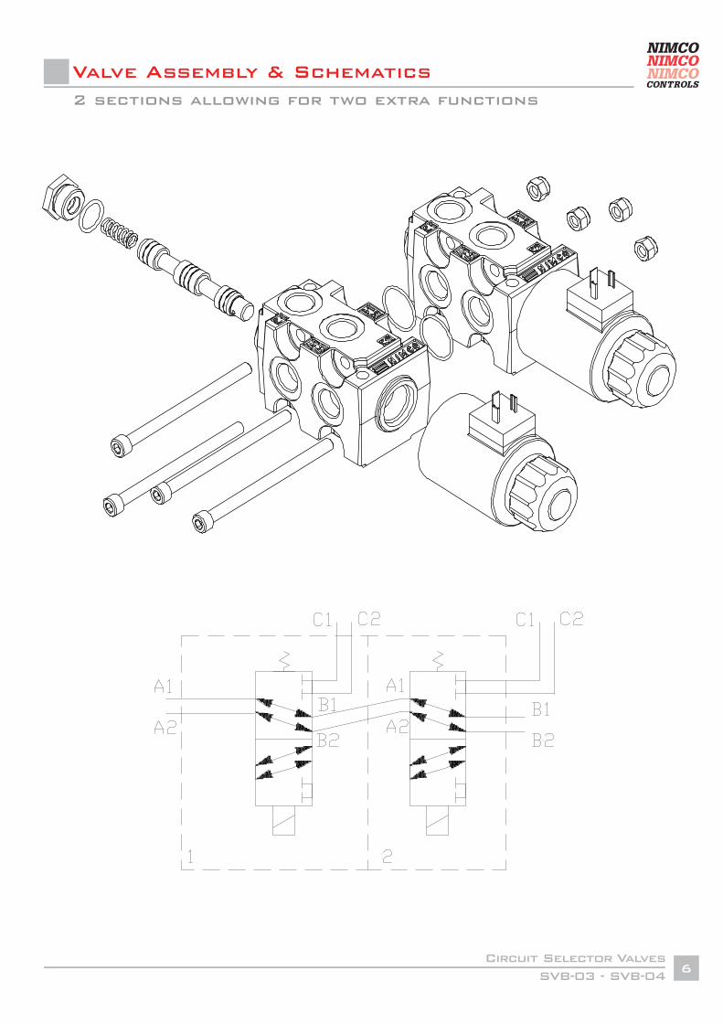
Valve Assembly & Schematics2 sections allowing for two extra functions
SVB-03 - SVB-04Circuit Selector Valves
7
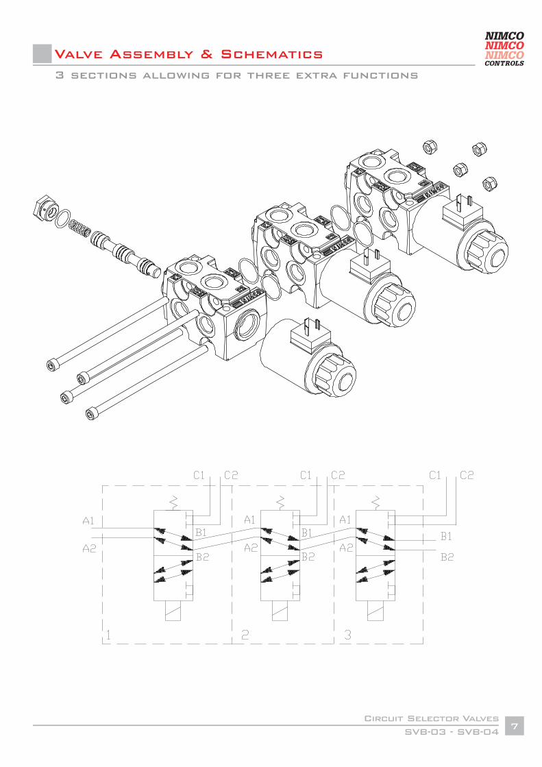
Valve Assembly & Schematics3 sections allowing for three extra functions
SVB-03 - SVB-04Circuit Selector Valves
8
Circuit Diagram N° 1
Circuit Diagram N° 2
Circuit Diagram N° 3
Applications and Ordering Codes
Valve type Cyl. port tThreads Voltage Bankable Cross-over
relief valvePressure setting B1
Pressure setting B2
SVB GS= G3/8’’GL= G1/2’’
M= M18 x 1,5S= SAE 8
3/4’’-16
12=12 V DC24=24 V DC
B=YesN=No
DRV=YesN=No
Adjustable 80-250 bar (1160-3600
psi) State setting
above!
Adjustable 80-250 bar (1160-3600
psi) State setting
above!
Write appropriate option codes (bold characters) in empty squares below and copy as order form!
Available options (select codes)
Ordering Codes
By means of an appropriate assembly kit, the SVB03/SVB04 valves can be banked to obtain e.g. 3 ways from two valves, etc. When marking “B” in the “Bankable” ordering square, an assembly kit is automatically delivered.
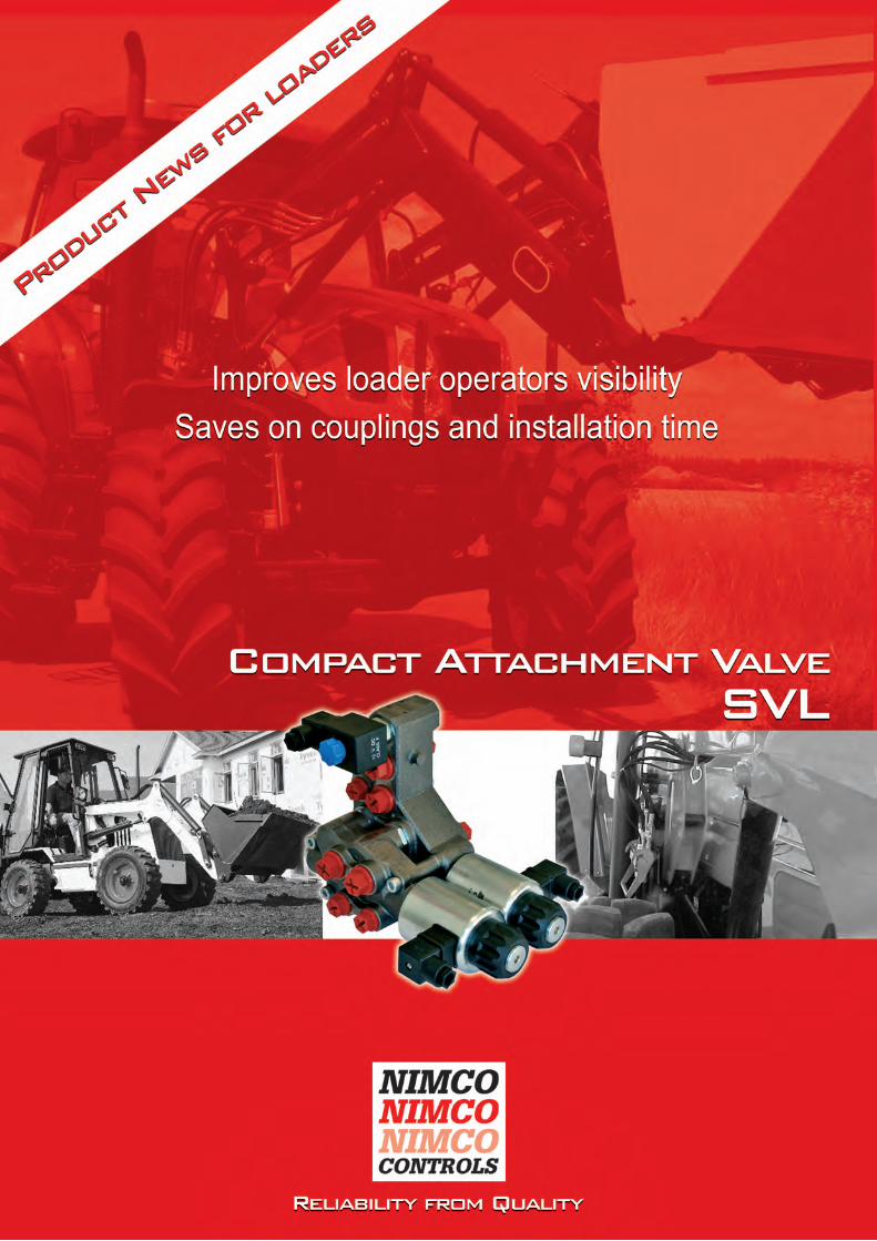
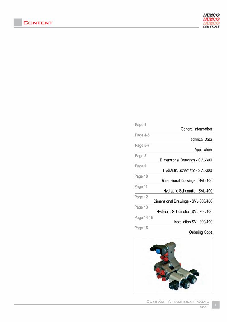
SVLCompact Attachment Valve
1
General Information
Technical Data
Application
Dimensional Drawings - SVL-300
Hydraulic Schematic - SVL-300
Dimensional Drawings - SVL-400
Hydraulic Schematic - SVL-400
Dimensional Drawings - SVL-300/400
Hydraulic Schematic - SVL-300/400
Installation SVL-300/400
Ordering Code
Page 10
Page 11
Page 12
Page 13
Page 14-15
Page 16
Page 3
Page 4-5
Page 6-7
Page 8
Page 9
Content
SVLCompact Attachment Valve
3
General Information
The SVL Compact Attachment valves are designed to be assembled on the cross beam of an agricultural loader. Through their special design they will combine standard and auxiliary functions that otherwise would have to be combined by a number of different valves while allowing for improved load visibility by the tractor operator.
The SVL-300 works as a central connecting point for all hoses from the loader valve which keeps all plumb-ing assembled close to the tractor. The SVL can also offer the control and plumbing to auxiliary functions, as needed.
The standard version of the valve (SVL-300-1) offers an integrated 6/2 circuit selector valve operation of a third machine function and two cross-over relief valves to protect the bucket circuit of a loader.The SVL-300-1 can also be combined with an additional 6/2 circuit selector valve for the electrical opera-tion of a fourth machine function. Through the possibility to mount the fourth function valve directly on to the SVL-300-1, the valve package remains small and keeps the visibility at an optimal level.
An added feature is the possibility to connect an accumulator for a more comfortable ride directly to the valve. The accumulator for the soft ride function can be activated either manually (SVL-300-2) or by an electrical 12 or 24-volt valve (SVL-300-3). The possibility to attach a fourth function valve like the SVL-400-1 is also given here.The SVL valve also offers the possibility to attach a tool lock valve to the valve block.
The SVL series is available with BSP, SAE and metric threads.
SVLCompact Attachment Valve
4
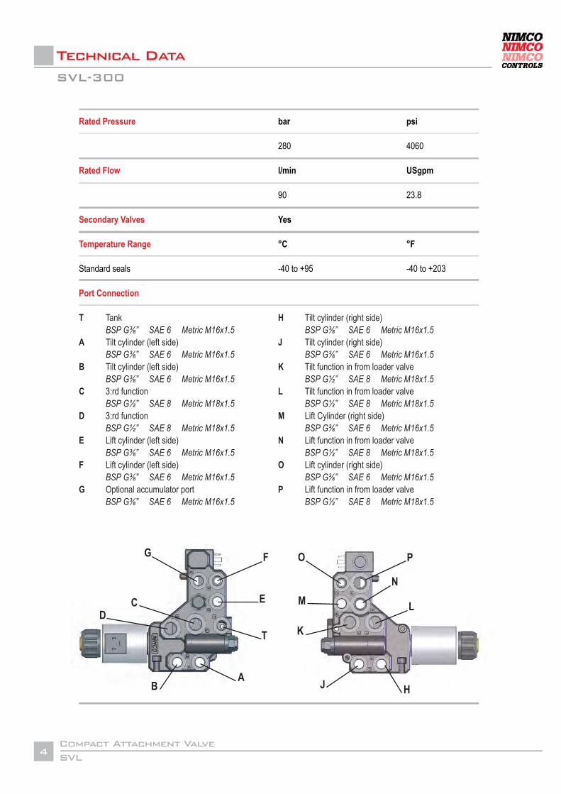
Technical Data
Rated Pressure
Rated Flow
Secondary Valves
Temperature Range
Standard seals
Port Connection
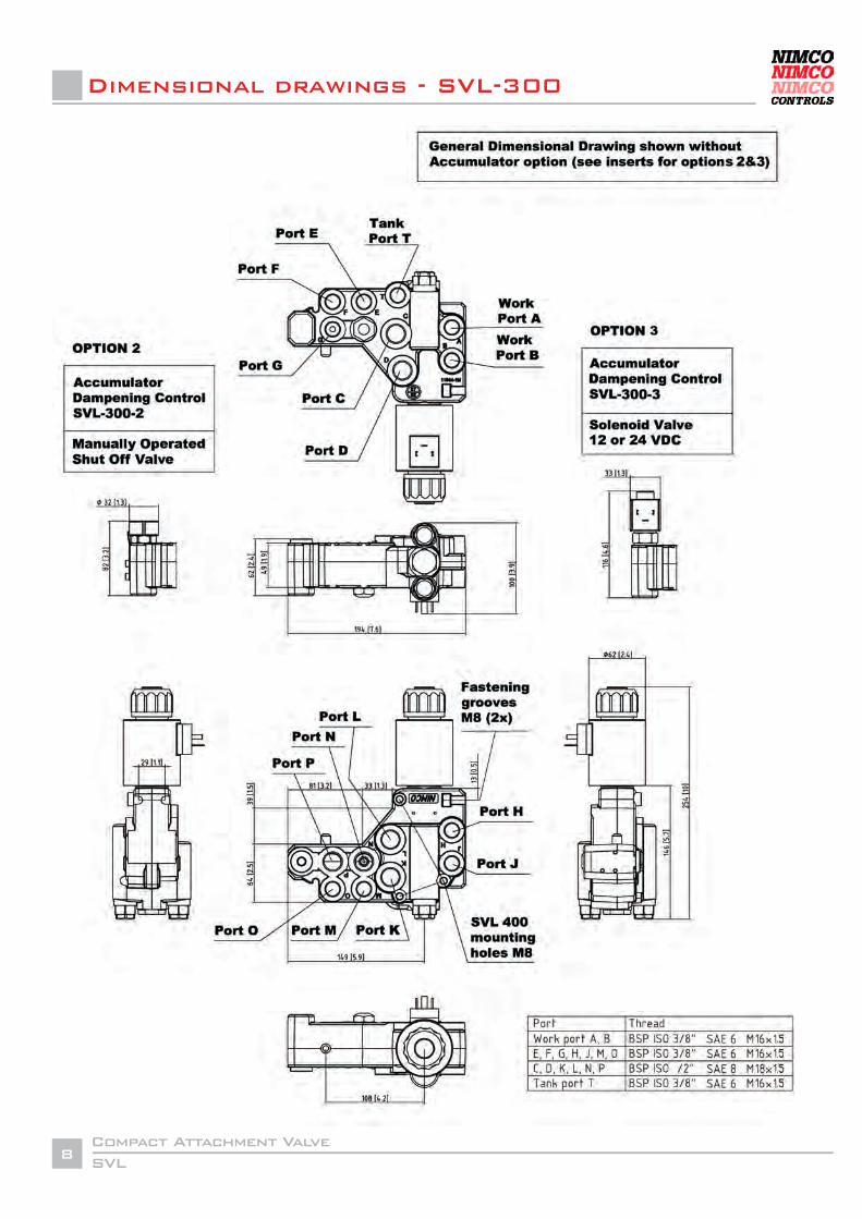
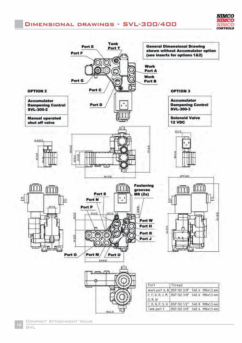
T Tank BSP G⅜” SAE 6 Metric M16x1.5A Tilt cylinder (left side) BSP G⅜” SAE 6 Metric M16x1.5B Tilt cylinder (left side) BSP G⅜” SAE 6 Metric M16x1.5C 3:rd function BSP G½” SAE 8 Metric M18x1.5D 3:rd function BSP G½” SAE 8 Metric M18x1.5E Lift cylinder (left side) BSP G⅜” SAE 6 Metric M16x1.5F Lift cylinder (left side) BSP G⅜” SAE 6 Metric M16x1.5G Optional accumulator port BSP G⅜” SAE 6 Metric M16x1.5
bar
280
l/min
90
Yes
°C
-40 to +95
H Tilt cylinder (right side) BSP G⅜” SAE 6 Metric M16x1.5J Tilt cylinder (right side) BSP G⅜” SAE 6 Metric M16x1.5K Tilt function in from loader valve BSP G½” SAE 8 Metric M18x1.5L Tilt function in from loader valve BSP G½” SAE 8 Metric M18x1.5M Lift Cylinder (right side) BSP G⅜” SAE 6 Metric M16x1.5N Lift function in from loader valve BSP G½” SAE 8 Metric M18x1.5O Lift cylinder (right side) BSP G⅜” SAE 6 Metric M16x1.5P Lift function in from loader valve BSP G½” SAE 8 Metric M18x1.5
psi
4060
USgpm
23.8
°F
-40 to +203
G F
ECD
T
AB
M
O P
N
L
K
J H
SVL-300
SVLCompact Attachment Valve
5
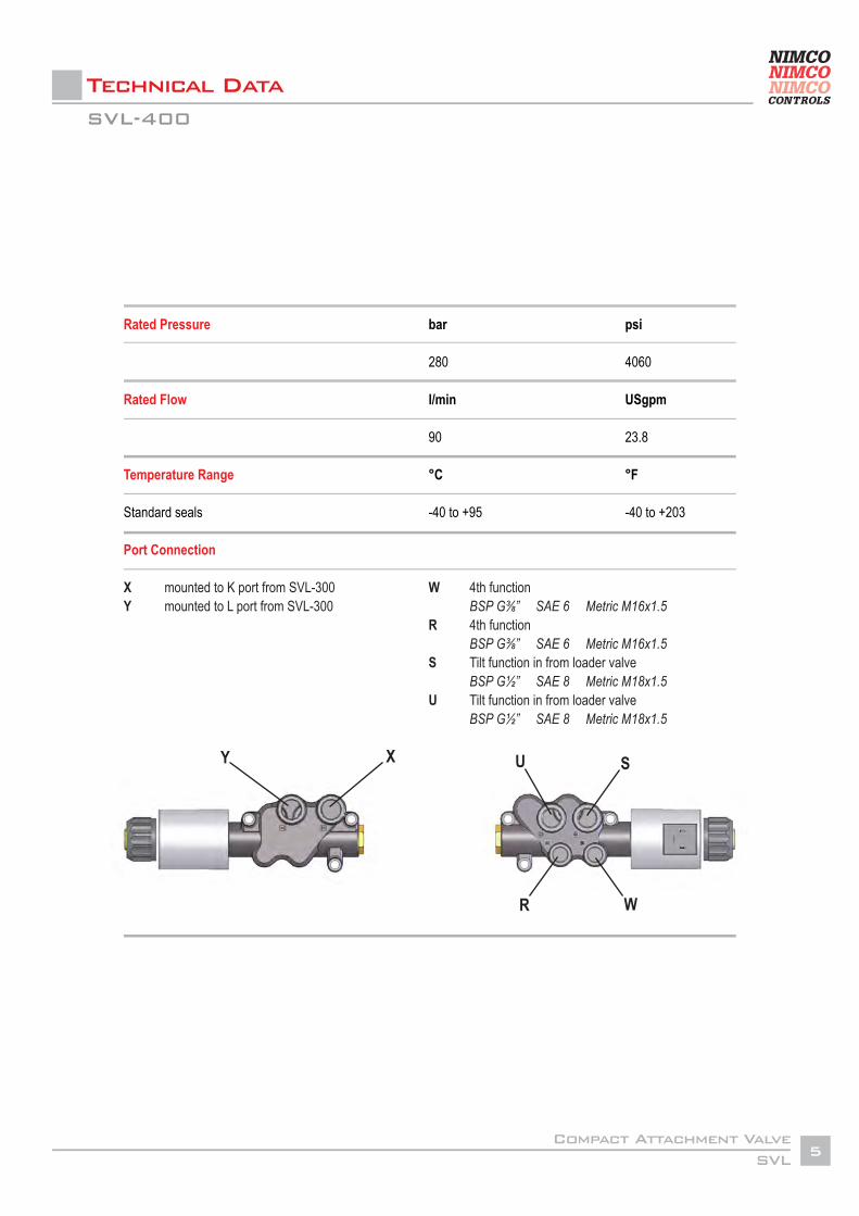
Technical Data
Rated Pressure
Rated Flow
Temperature Range
Standard seals
Port Connection
X mounted to K port from SVL-300Y mounted to L port from SVL-300
bar
280
l/min
90
°C
-40 to +95
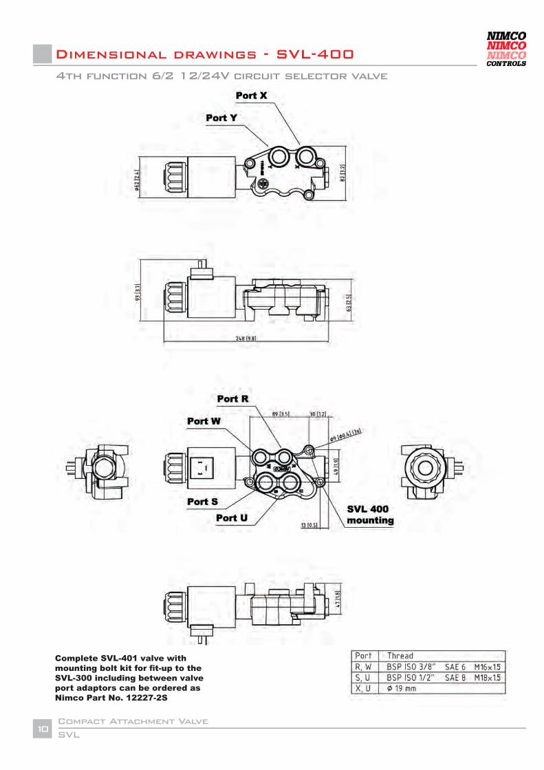
W 4th function BSP G⅜” SAE 6 Metric M16x1.5R 4th function BSP G⅜” SAE 6 Metric M16x1.5S Tilt function in from loader valve BSP G½” SAE 8 Metric M18x1.5 U Tilt function in from loader valve BSP G½” SAE 8 Metric M18x1.5
psi
4060
USgpm
23.8
°F
-40 to +203
Y X U S
WR
SVL-400
SVLCompact Attachment Valve
6
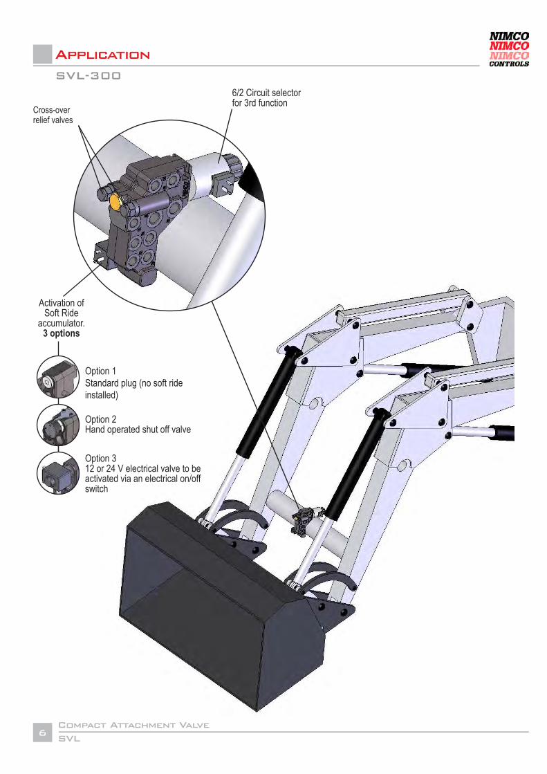
Application
6/2 Circuit selector for 3rd function
Cross-overrelief valves
Activation of Soft Ride
accumulator.3 options
SVL-300
Option 1 Standard plug (no soft ride installed)
Option 312 or 24 V electrical valve to be activated via an electrical on/off switch
Option 2Hand operated shut off valve
SVLCompact Attachment Valve
7
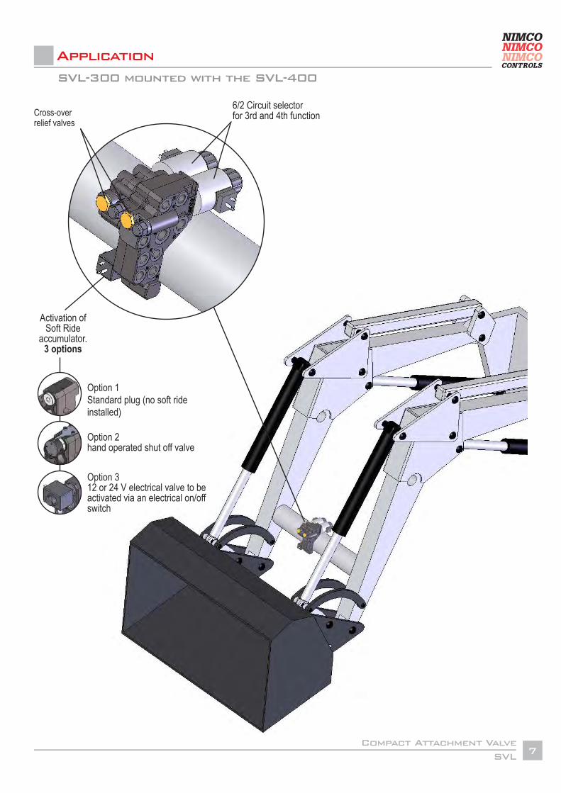
SVL-300 mounted with the SVL-400
Application
6/2 Circuit selector for 3rd and 4th function
Activation of Soft Ride
accumulator.3 options
Option 1Standard plug (no soft ride installed)
Option 312 or 24 V electrical valve to be activated via an electrical on/off switch
Option 2hand operated shut off valve
Cross-overrelief valves
SVLCompact Attachment Valve
8
Dimensional drawings - SVL-300
SVLCompact Attachment Valve
9
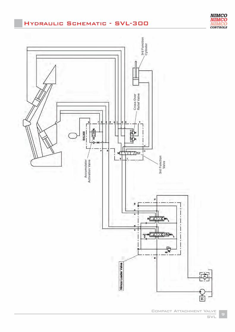
Hydraulic Schematic - SVL-300
SVLCompact Attachment Valve
10
Dimensional drawings - SVL-400
Complete SVL-401 valve with mounting bolt kit for fit-up to the SVL-300 including between valve port adaptors can be ordered as Nimco Part No. 12227-2S
4th function 6/2 12/24V circuit selector valve
SVLCompact Attachment Valve
11
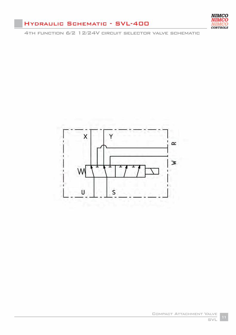
Hydraulic Schematic - SVL-4004th function 6/2 12/24V circuit selector valve schematic
SVLCompact Attachment Valve
12
Dimensional drawings - SVL-300/400
SVLCompact Attachment Valve
13
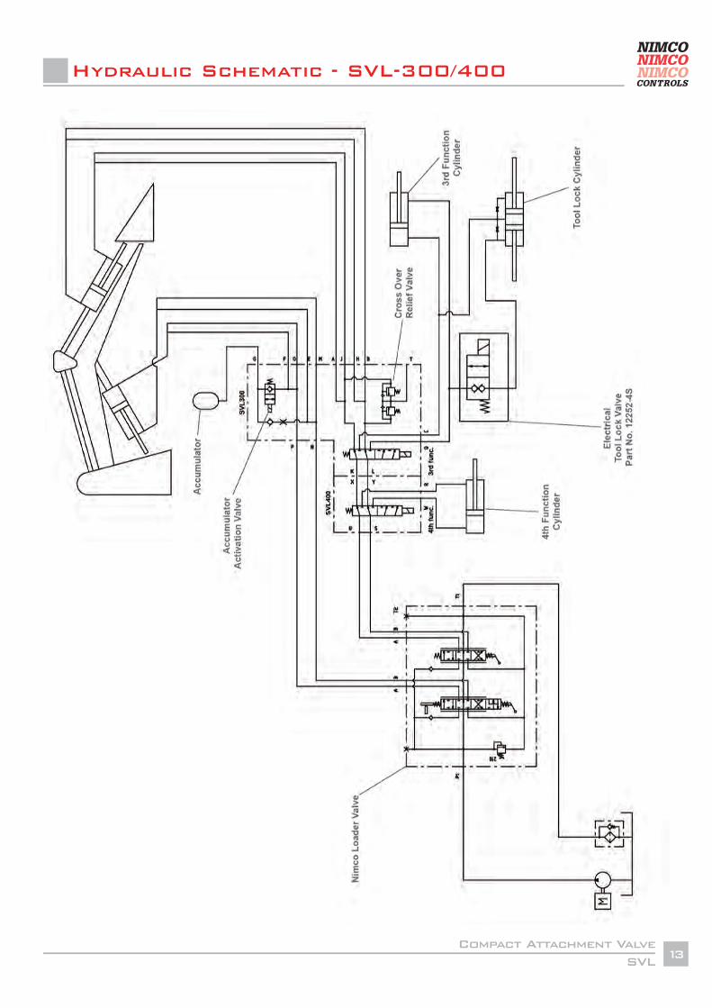
Hydraulic Schematic - SVL-300/400
SVLCompact Attachment Valve
14
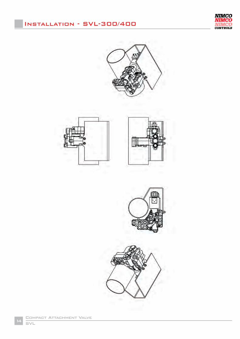
Installation - SVL-300/400
SVLCompact Attachment Valve
15
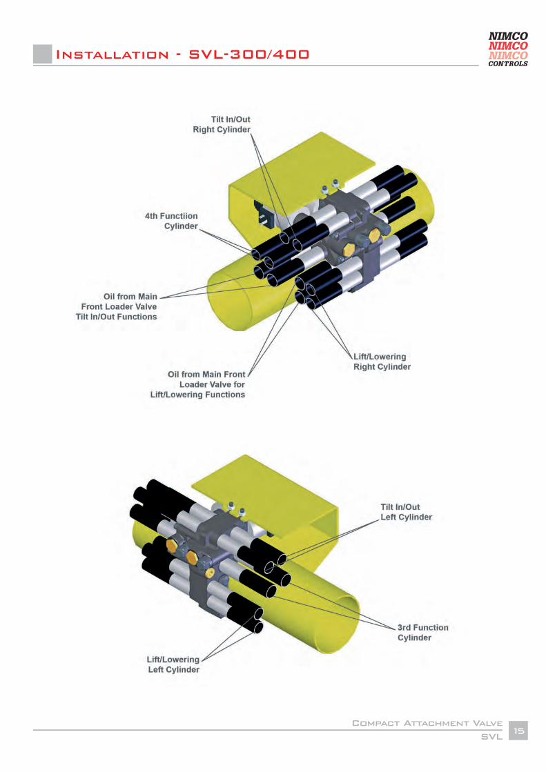
Installation - SVL-300/400
SVLCompact Attachment Valve
16
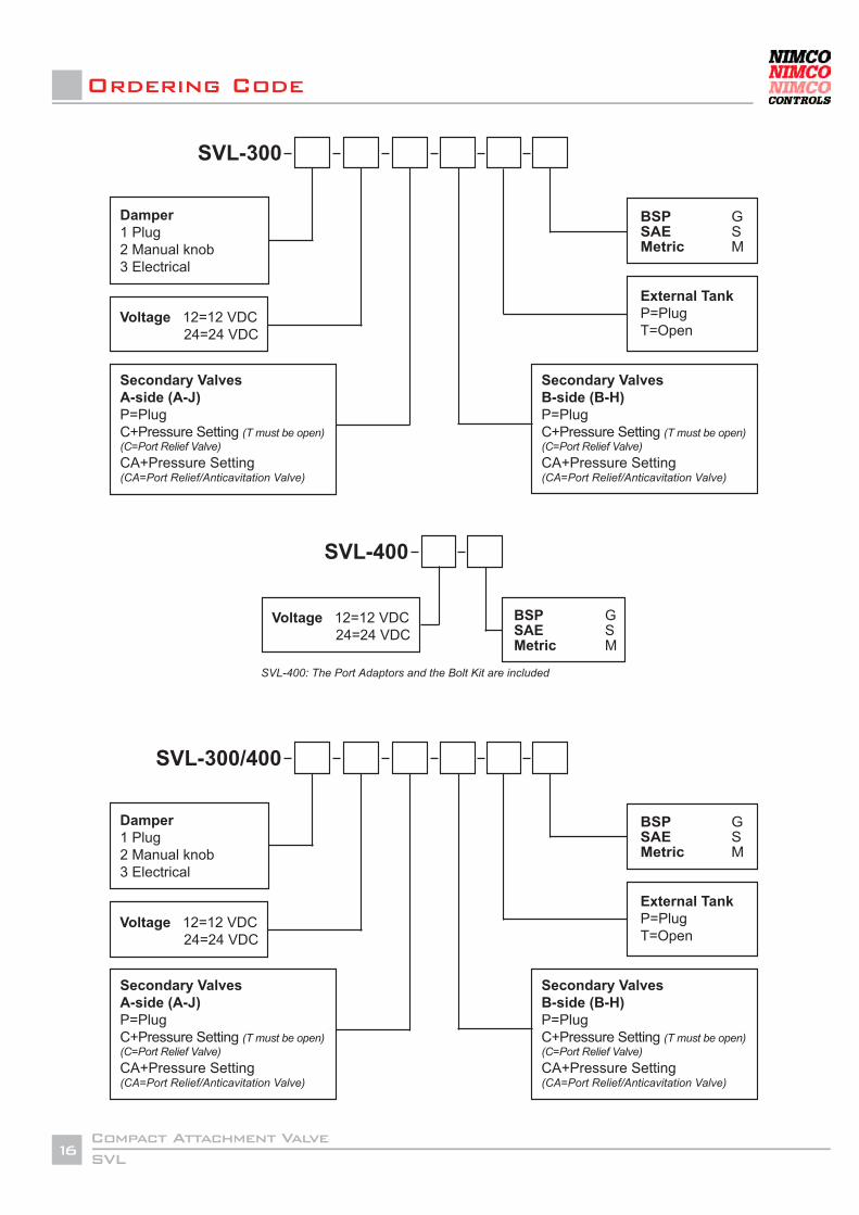
Ordering Code
SVL-400: The Port Adaptors and the Bolt Kit are included
SVL-300
BSP GSAE SMetric M
External Tank P=PlugT=Open
Voltage 12=12 VDC 24=24 VDC
Damper1 Plug2 Manual knob3 Electrical
Secondary ValvesA-side (A-J) P=PlugC+Pressure Setting (T must be open)(C=Port Relief Valve)CA+Pressure Setting(CA=Port Relief/Anticavitation Valve)
Secondary ValvesB-side (B-H) P=PlugC+Pressure Setting (T must be open)(C=Port Relief Valve)CA+Pressure Setting(CA=Port Relief/Anticavitation Valve)
SVL-300/400
SVL-400
BSP GSAE SMetric M
Voltage 12=12 VDC 24=24 VDC
SVL 400
BSP GSAE SMetric M
Bolt KitY=YesN=No
Port Adaptors to SVL-300Y=YesN=No
Voltage 12=12 VDC 24=24 VDC
Related Documents