Citation: Sondermann, L.; Jiang, W.; Shviro, M.; Spieß, A.; Woschko, D.; Rademacher, L.; Janiak, C. Nickel-Based Metal-Organic Frameworks as Electrocatalysts for the Oxygen Evolution Reaction (OER). Molecules 2022, 27, 1241. https://doi.org/10.3390/ molecules27041241 Academic Editors: Jingqi Guan and Yin Wang Received: 21 January 2022 Accepted: 6 February 2022 Published: 12 February 2022 Publisher’s Note: MDPI stays neutral with regard to jurisdictional claims in published maps and institutional affil- iations. Copyright: © 2022 by the authors. Licensee MDPI, Basel, Switzerland. This article is an open access article distributed under the terms and conditions of the Creative Commons Attribution (CC BY) license (https:// creativecommons.org/licenses/by/ 4.0/). molecules Article Nickel-Based Metal-Organic Frameworks as Electrocatalysts for the Oxygen Evolution Reaction (OER) Linda Sondermann 1 , Wulv Jiang 2 , Meital Shviro 2, * , Alex Spieß 1 , Dennis Woschko 1 , Lars Rademacher 1 and Christoph Janiak 1, * 1 Institut für Anorganische Chemie und Strukturchemie, Heinrich-Heine-Universität Düsseldorf, 40225 Düsseldorf, Germany; [email protected] (L.S.); [email protected] (A.S.); [email protected] (D.W.); [email protected] (L.R.) 2 Forschungszentrum Jülich GmbH, Institute of Energy and Climate Research, IEK-14: Electrochemical Process Engineering, 52425 Jülich, Germany; [email protected] * Correspondence: [email protected] (M.S.); [email protected] (C.J.); Tel.: +49-211-81-12286 (C.J.) Abstract: The exploration of earth-abundant electrocatalysts with high performance for the oxygen evolution reaction (OER) is eminently desirable and remains a significant challenge. The composite of the metal-organic framework (MOF) Ni 10 Co-BTC (BTC = 1,3,5-benzenetricarboxylate) and the highly conductive carbon material ketjenblack (KB) could be easily obtained from the MOF synthesis in the presence of KB in a one-step solvothermal reaction. The composite and the pristine MOF perform better than commercially available Ni/NiO nanoparticles under the same conditions for the OER. Activation of the nickel-cobalt clusters from the MOF can be seen under the applied anodic potential, which steadily boosts the OER performance. Ni 10 Co-BTC and Ni 10 Co-BTC/KB are used as sacrificial agents and undergo structural changes during electrochemical measurements, the stabilized materials show good OER performances. Keywords: metal-organic frameworks (MOF); electrocatalysis; oxygen evolution reaction (OER); nickel; ketjenblack 1. Introduction The depletion of fossil fuels and their direct correlation in increasing global greenhouse gas emissions through their combustion show that the development of new sustainable clean energy sources is required [1–3]. A possible solution is coupling renewable energy sources like solar and wind energy with electrochemical water splitting to convert surplus electrical energy into storable hydrogen fuel [4–7]. Electrochemical water splitting consists of two half reactions, the cathodic hydrogen evolution reaction (HER; alkaline conditions: 4H 2 O+4e - → 2H 2 + 4 OH - ,E ◦ = 0.00 V vs. RHE) and the anodic oxygen evolution reaction (OER, alkaline conditions: 4 OH - → O 2 +4e - +2H 2 O, E ◦ = 1.23 V vs. RHE) [8,9]. The OER involves a four electron-proton coupled transfer process to generate one oxygen molecule and occurs at an applied potential (overpotential η) much higher than the the- oretical equilibrium potential of E ◦ = 1.23 V vs. RHE [8,10–14]. The overpotential is the difference between the applied potential and the equilibrium potential η OER =E RHE - E ◦ (1.23 V) (1) and it is one of the key parameters on which the performance of an electrocatalyst is evaluated on [9,15,16]. Ideally a highly active electrocatalyst produces a large current density with a small overpotential [11] together with long-term stability. Another key parameter, which gives insight into the reaction mechanism and rate-determining step, is the Tafel slope (b), which can be obtained through the Tafel-equation [12,17,18]. η = a + b × log(j) (2) Molecules 2022, 27, 1241. https://doi.org/10.3390/molecules27041241 https://www.mdpi.com/journal/molecules

Welcome message from author
This document is posted to help you gain knowledge. Please leave a comment to let me know what you think about it! Share it to your friends and learn new things together.
Transcript

�����������������
Citation: Sondermann, L.; Jiang, W.;
Shviro, M.; Spieß, A.; Woschko, D.;
Rademacher, L.; Janiak, C.
Nickel-Based Metal-Organic
Frameworks as Electrocatalysts for
the Oxygen Evolution Reaction
(OER). Molecules 2022, 27, 1241.
https://doi.org/10.3390/
molecules27041241
Academic Editors: Jingqi Guan
and Yin Wang
Received: 21 January 2022
Accepted: 6 February 2022
Published: 12 February 2022
Publisher’s Note: MDPI stays neutral
with regard to jurisdictional claims in
published maps and institutional affil-
iations.
Copyright: © 2022 by the authors.
Licensee MDPI, Basel, Switzerland.
This article is an open access article
distributed under the terms and
conditions of the Creative Commons
Attribution (CC BY) license (https://
creativecommons.org/licenses/by/
4.0/).
molecules
Article
Nickel-Based Metal-Organic Frameworks as Electrocatalysts forthe Oxygen Evolution Reaction (OER)Linda Sondermann 1, Wulv Jiang 2 , Meital Shviro 2,* , Alex Spieß 1, Dennis Woschko 1, Lars Rademacher 1 andChristoph Janiak 1,*
1 Institut für Anorganische Chemie und Strukturchemie, Heinrich-Heine-Universität Düsseldorf,40225 Düsseldorf, Germany; [email protected] (L.S.); [email protected] (A.S.);[email protected] (D.W.); [email protected] (L.R.)
2 Forschungszentrum Jülich GmbH, Institute of Energy and Climate Research, IEK-14: Electrochemical ProcessEngineering, 52425 Jülich, Germany; [email protected]
* Correspondence: [email protected] (M.S.); [email protected] (C.J.); Tel.: +49-211-81-12286 (C.J.)
Abstract: The exploration of earth-abundant electrocatalysts with high performance for the oxygenevolution reaction (OER) is eminently desirable and remains a significant challenge. The composite ofthe metal-organic framework (MOF) Ni10Co-BTC (BTC = 1,3,5-benzenetricarboxylate) and the highlyconductive carbon material ketjenblack (KB) could be easily obtained from the MOF synthesis in thepresence of KB in a one-step solvothermal reaction. The composite and the pristine MOF performbetter than commercially available Ni/NiO nanoparticles under the same conditions for the OER.Activation of the nickel-cobalt clusters from the MOF can be seen under the applied anodic potential,which steadily boosts the OER performance. Ni10Co-BTC and Ni10Co-BTC/KB are used as sacrificialagents and undergo structural changes during electrochemical measurements, the stabilized materialsshow good OER performances.
Keywords: metal-organic frameworks (MOF); electrocatalysis; oxygen evolution reaction (OER);nickel; ketjenblack
1. Introduction
The depletion of fossil fuels and their direct correlation in increasing global greenhousegas emissions through their combustion show that the development of new sustainableclean energy sources is required [1–3]. A possible solution is coupling renewable energysources like solar and wind energy with electrochemical water splitting to convert surpluselectrical energy into storable hydrogen fuel [4–7]. Electrochemical water splitting consistsof two half reactions, the cathodic hydrogen evolution reaction (HER; alkaline conditions:4 H2O + 4 e− → 2 H2 + 4 OH−, E◦ = 0.00 V vs. RHE) and the anodic oxygen evolutionreaction (OER, alkaline conditions: 4 OH−→ O2 + 4 e− + 2 H2O, E◦ = 1.23 V vs. RHE) [8,9].The OER involves a four electron-proton coupled transfer process to generate one oxygenmolecule and occurs at an applied potential (overpotential η) much higher than the the-oretical equilibrium potential of E◦ = 1.23 V vs. RHE [8,10–14]. The overpotential is thedifference between the applied potential and the equilibrium potential
ηOER = ERHE − E◦ (1.23 V) (1)
and it is one of the key parameters on which the performance of an electrocatalyst isevaluated on [9,15,16]. Ideally a highly active electrocatalyst produces a large currentdensity with a small overpotential [11] together with long-term stability. Another keyparameter, which gives insight into the reaction mechanism and rate-determining step, isthe Tafel slope (b), which can be obtained through the Tafel-equation [12,17,18].
η = a + b× log(j) (2)
Molecules 2022, 27, 1241. https://doi.org/10.3390/molecules27041241 https://www.mdpi.com/journal/molecules

Molecules 2022, 27, 1241 2 of 16
Up to date electrocatalysts based on noble metals, such as ruthenium and iridium,together with their oxides RuO2 and IrO2, are the OER-catalysts with the best performance,independently of the pH of the electrolyte [19–21]. However, the scarcity and high costsof these noble metals severely hinder a large-scale industrial application. Subsequentresearch has been directed towards the development of non-noble metal alternatives forthe OER [22,23]. Research focuses on finding active, stable and inexpensive electrocatalysts,where especially 3d-transition-metals such as Fe, Ni and Co are of high interest [7,24,25].Recently metal-organic frameworks (MOFs) and MOF-based electrocatalysts have been paidmuch attention [26,27]. MOFs are potentially porous, crystalline coordination networkswith metal nodes and bridging organic ligands [28,29]. MOFs have been investigated aselectrocatalysts due to their high porosity, large surface areas, diversity of composition andstructure [27,30–33]. MOFs can be used directly for electrocatalytic reactions, but they havedrawbacks like (i) low electrical conductivity, (ii) mass transport problems of reactants,products and electrolyte ions through their micropores, (iii) lack of stability especially inhighly acidic or alkaline aqueous environments [34]. Because of those drawbacks, MOFsare often employed as precursors or sacrificial agents to construct structured carbon-basedmetal oxide materials as efficient electrocatalysts [27,32,35]. To increase the low electricconductivity and the electrocatalytic performance of MOFs carbon supports are added suchas graphene [36], carbon nanotubes (CNTs) [21] or ketjenblack (KB) [37]. The performanceof Ni-MOF electrocatalysts could be enhanced by the introduction of a second metalsuch as cobalt or iron [35,38–41]. Our previous work has shown that a Ni(Fe)-MOF/KBcomposite exhibited remarkable OER performance [34]. The MOF Ni-BTC and Ni(Fe)-BTC(BTC = 1,3,5-benzenetricarboxylate) have a fast charge transfer rate and high activity for theOER [40,42]. A mixed-metal Ni(Co)-BTC MOF has only been used as a sacrificial agent togive NiCo2O4 [35], which encouraged us to take a closer look at the activity of the pristineMOF and the composite material including KB for the OER in this work.
2. Results and Discussion2.1. Synthesis and Characterization of the Ni-BTC Analogs
The Ni-BTC structure is identical to the Cu-BTC or HKUST-1 structure (HKUST = HongKong University of Science and Technology) [43] both are built by dinuclear metal(II)-secondary building units (SBUs), which are connected by BTC in a paddle-wheel fashionto a three-dimensional network of formula [Ni3(BTC)2] [43,44]. The composite of Ni10Co-BTC and KB, named Ni10Co-BTC/KB was generated through a facile MOF synthesisin the presence of ketjenblack (KB) in a one-step solvothermal reaction at 170 ◦C for48 h from a mixture of Ni(NO3)2· 6 H2O, Co(NO3)2· 6 H2O (molar Ni:Co ratio 10:1),1,3,5-benzenetricarboxylic acid (H3BTC), 2-methylimidazole (2-MeImH), and KB in N,N-dimethylformamide (DMF) (Figure 1). Ni10Co-BTC and Ni10Fe-BTC were synthesizedfor comparison. Ni-BTC and the mixed-metal analogs are obtained as the dimethylamineadduct [Ni3(BTC)2(Me2NH)3] at the axial metal position with Me2NH being a hydrolysisproduct of DMF [43] (from the CHN elemental analysis data in Table S1, SupportingInformation (SI)).

Molecules 2022, 27, 1241 3 of 16
Figure 1. Schematic illustration of the Ni10Co-BTC/KB composite synthesis.
A well-known phenomenon in mixed-metal MOF synthesis is that the incorporatedmetal ratio can differ from the starting material ratio and must be post-synthetically quanti-fied. To quantify the amount of Co and Fe in the synthesized Ni10Co-BTC and Ni10Fe-BTCflame atomic absorption spectroscopy (AAS) was conducted post-synthetically, resulting ina molar Ni:Co ratio of 11:1 for Ni10Co-BTC and a molar Ni:Fe ratio of 11:1 for Ni10Fe-BTC(Table 1).
Table 1. SEM-EDX and AAS results of the mixed-metal samples.
Sample SEM-EDX AAS *
Molar Ratio Metal wt.% Approximate Molar Ratio
Ni Fe/Co Ni Fe/Co Ni Fe/Co
Ni10Fe-BTC 9 1 16.7 1.5 11 1Ni10Co-BTC 7 1 16.3 1.5 11 1
Ni10Co-BTC/KB 7 1 10.6 1.3 8 1* Atomic absorption spectroscopy. Weighted samples were heated to dryness with aqua regia for two times andafterwards stirred with aqua regia overnight. The solution was carefully filtered and diluted with Milliporewater to a volume of 25 mL. The resulting solutions were further diluted with Millipore water (1:50) for the AASmeasurements.
From the AAS determined metal wt.%, the mass fractions of the MOF in the KBcomposites were calculated as 67 wt.% Ni10Co-BTC together with 33 wt.% KB.
Powder X-ray diffraction (PXRD) patterns of Ni10Fe-BTC, Ni10Co-BTC, Ni10Co-BTC/KB,KB and a simulated diffraction pattern of Ni-BTC are illustrated in Figure 2a. The pristineMOF samples Ni10Fe-BTC and Ni10Co-BTC exhibit the same reflexes as the simulated pat-tern of Ni-BTC. The composite Ni10Co-BTC/KB also demonstrated a PXRD pattern, whichagrees to the simulated pattern of Ni-BTC and also the pristine MOF Ni10Co-BTC. Theaforementioned PXRD patterns show that the addition of amorphous KB in the synthesisdid not influence the MOF crystal growth and structure significantly [45,46]. Apart fromthe reflexes of the simulated Ni-BTC MOF there are no additional reflexes in the diffractionpatterns of the samples, which reveals that no iron or cobalt(oxy)hydroxides formed inthe synthesis. This indicates that the second metal (iron or cobalt) was well incorporatedinto the structure of the Ni-BTC MOF. Pure KB displayed three broad diffraction peakscorresponding to the (100), (002), (101) planes of amorphous carbon [47,48].

Molecules 2022, 27, 1241 4 of 16
Figure 2. (a) PXRD patterns of experimental Ni10Fe-BTC (red), Ni10Co-BTC (green), Ni10Co-BTC/KB(orange), KB (blue) and simulated Ni-BTC (black) (CCDC Nr. 802889); (b) FT-IR spectra of Ni10Fe-BTC(red), Ni10Co-BTC (green), Ni10Co-BTC/KB (orange) and KB (blue).
Fourier transform infrared (FT-IR) spectra (Figure 2b) of the Ni-BTC analogs demon-strate the same characteristic bands (listed in Table S2, SI) which are in a good agreementwith the literature [39]. A broad band in the region of 3600–3000 cm–1 and a band around1650 cm−1 can be attributed to the stretching and bending vibrations of -OH group fromadsorbed or coordinated water [43,49–51]. Characteristic vibrations of a Ni-O bond 577–460 cm−1 [51] and of carboxylate-groups 1617–1556 cm−1 (asymmetric vibration) and1439–1364 cm−1 (symmetric vibration) can be observed in all samples [50,52]. Vibrationsof a Fe-O bond are reported at 538 and 634 cm−1 and of a Fe2Ni-O bond at ca. 720 cm−1,which is also in the range of the vibration of a Co-O bond (725 cm−1) [53–55]. Fe-O couldnot be detected and the Fe2Ni-O and Co-O bonds are all in a similar range to each otherand to aromatic vibrations (Table S2, SI).
The specific Brunauer-Emmett-Teller (BET) surface areas and pore volumes of thematerials were derived from nitrogen-adsorption isotherms at 77 K (Figure 3a) and aregiven in Table S3, SI.
Figure 3. (a) N2-sorption isotherms at 77 K (Adsorption: filled circles; desorption: empty circles),(b) pore size distributions of Ni10Fe-BTC (red), Ni10Co-BTC (green), Ni10Co-BTC/KB (orange) andKB (blue).

Molecules 2022, 27, 1241 5 of 16
The BET surface areas of the Ni-BTC analogs (Ni10Fe-BTC: 555 m2/g, Ni10Co-BTC:303 m2/g and Ni10Co-BTC/KB: 596 m2/g) are all in the range of reported values for neatNi-BTC (Ni-BTCDMF/EtOH: 198 m2/g and 252 m2/g, Ni-BTCEtOH: 551 m2/g; Ni-BTC:0.286 cm3/g) [56,57]. Ni10Fe-BTC and Ni10Co-BTC show a type I isotherm revealing theirmicroporosity with a steep gas uptake at low relative pressure followed by a plateau [58–60].KB is a porous carbon material with a BET surface area of 1415 m2/g, a pore volume of1.59 cm3/g (Table S3, SI) and mesopores, which are mostly around 4 ± 2 nm (Figure 3b).The adsorption isotherm branch of KB is a composite of a type I and II isotherm andthe desorption isotherm branch additionally displays a H4 hysteresis, both being oftenindicators for micro-mesoporous carbons [58]. The nitrogen sorption isotherm and BET-surface area of the composite Ni10Co-BTC/KB is a superposition of the isotherms of theMOF and KB components (Figure 3a). This superposition also holds for the pore-sizedistribution of the individual components in the composite (Figure 3b). The bimodalpore size distribution of Ni10Co-BTC/KB with maxima at ~2 nm and ~4 nm reflects thecontributions from the MOF and KB. Consequently, the BET surface area and pore volumeof the Ni10Co-BTC/KB composite with 596 m2/g and 0.45 cm3/g, respectively, are higherthan the surface area and pore volume of neat Ni10Co-BTC (303 m2/g, 0.15 cm3/g) but stilllower than the calculated BET surface area (670 m2/g) as determined from the sum of themass-weighted S(BET) of KB (33 wt.%) and MOF (67 wt.%) (Equation (3) [34]):
S(BET)calc. =wt.% of KB
100× S(BET)KB +
wt.% of MOF100
× S(BET)MOF (3)
The slightly lower BET surface area can be due to pore blocking effects or formation ofthe MOF in the mesopores of KB, as evidenced by the large reduction of the incrementalmesopore volume in Figure 3b.
Thermogravimetric analyses (TGA) under N2 atmosphere yield a similar curvaturefor all Ni-BTC analogs (Figure S1, SI). In the range of 30–320 ◦C the initial weight lossesuntil decomposition can be attributed to the loss of crystal solvent molecules (DMF, H2O)incorporated in the cavities [61]. After complete solvent loss the BTC-linker together withthe MOF structure decomposes around 350–600 ◦C (Lit. 337–450 ◦C) (mass change of54–57 %, Figure S1, SI) [56,60]. The TGA curves are in agreement with reported curves forNiCo-BTC and Ni-BTC [35,43,60,61].
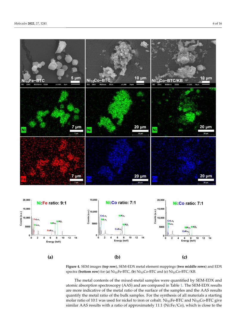
Scanning electron microscopy (SEM) images of Ni10Fe-BTC (Figure 4a) present spher-ical and cubic particles, which is in accordance with the literature [40]. Ni10Co-BTC(Figure 4b) has irregular shaped aggregates similar to reported Ni-BTC [40]. The KB parti-cles (Figure S3, SI) are smaller than the MOF particles, and do not have a clearly definedshape. In the composite material Ni10Co-BTC/KB (Figure 4c) the MOF particles are coveredby KB. SEM-energy-dispersive X-ray spectroscopy (EDX) was conducted for the mixed-metal MOFs (Figure 4 and Figure S2, SI) and KB (Figure S3, SI). For the mixed-metal MOFsSEM-EDX metal element mapping (Figure 4) reveals a good superposition of the twodifferent metals. It is evident that the mapping of nickel and iron or cobalt of Ni10Fe-BTCand Ni10Co-BTC, respectively, is more visible than for Ni10Co-BTC/KB, where the KBpartially covers and masks surface of the MOF particles.
Molecules 2022, 27, 1241 6 of 16
Figure 4. SEM images (top row), SEM-EDX metal element mappings (two middle rows) and EDXspectra (bottom row) for (a) Ni10Fe-BTC, (b) Ni10Co-BTC and (c) Ni10Co-BTC/KB.
The metal contents of the mixed-metal samples were quantified by SEM-EDX andatomic absorption spectroscopy (AAS) and are compared in Table 1. The SEM-EDX resultsare more indicative of the metal ratio of the surface of the samples and the AAS resultsquantify the metal ratio of the bulk samples. For the synthesis of all materials a startingmolar ratio of 10:1 was used for nickel to iron or cobalt. Ni10Fe-BTC and Ni10Co-BTC givesimilar AAS results with a ratio of approximately 11:1 (Ni:Fe/Co), which is close to the

Molecules 2022, 27, 1241 7 of 16
used 10:1 molar ratio for the synthesis. The AAS of the composite material Ni10Co-BTC/KBresults in a Ni:Co ratio of approximately 8:1, which is a little lower than the implementedmolar ratio in the beginning.
2.2. Electrocatalytical Results
The OER performance of all samples was checked using a three-electrode systemwith rotation disk electrode in 1 mol/L KOH electrolyte. The electrochemical kineticsof the samples were evaluated by comparison of the Tafel slopes derived from linearsweep voltammetry (LSV) curves after the activation. Apart from the overpotential andTafel slope the stability of the electrocatalysts were examined by comparing the overpo-tential before and after 1000 cyclic voltammetry cycles (CVs). Details are given in theexperimental section.
The LSV curves in Figure 5a,b show that Ni10Fe-BTC reaches the highest currentdensity before the stability test in comparison to the reference commercial Ni/NiO nanopar-ticles, Ni10Co-BTC, Ni10Co-BTC/KB and KB. The LSV curves in Figure 5b display thatthe current density of Ni10Co-BTC/KB was higher than that of the pristine MOF or KBbefore the stability test, which could be due to a conductivity enhancement effect by theintroduction of KB. After the stability test the achieved current density of the pristine MOFis higher than the composite and both are higher than the current density of KB. The cur-rent densities of Ni10Fe-BTC and of KB have declined after the stability test. Ni10Co-BTC,Ni10Co-BTC/KB and the commercial Ni/NiO nanoparticles reach a higher current densityafter the stability test. The peaks from 1.3 to 1.4 V vs. RHE in Figure 5b originated fromthe redox reaction of Ni2+/3+ [35,62,63]. The redox peaks are less visible for Ni10Fe-BTC,which is due to the well-known suppressor effect of Fe for the Ni2+/3+ oxidation [64–66].The changed current densities before and after the 1000 CVs already depict that an acti-vation is taking place in case of the NiCo samples and the Ni/NiO nanoparticles. Theefficiency of an electrocatalyst is normally checked with the overpotential at a currentdensity (j) of 10 mA/cm2, which relates to the approximate current density expected fora 10% efficient solar-to-fuel conversion device under sun illumination [13,67,68]. To havea more defined indicator the initial overpotential and the overpotential after the stabilitytest to reach 10 mA/cm2 should be considered. Ni10Fe-BTC reaches 10 mA/cm2 with aninitial overpotential of 346 mV and an overpotential of 344 mV after the stability test. Themeasurement done after the stability test shows nearly identical values, which indicatesthat the material is stable in its OER performance. The results show that Ni10Fe-BTChas a relatively good OER performance. The overpotentials needed to reach 10 mA/cm2
before and after the stability test and Tafel slopes for KB, Ni10Co-BTC/KB, Ni10Co-BTCand Ni/NiO nanoparticles including the results of Ni10Fe-BTC are listed in Table S4, SI.Ni10Co-BTC (η = 378 mV → 337 mV), Ni10Co-BTC/KB (η = 366 mV → 347 mV) MOFsamples and the Ni/NiO nanoparticles (η = 370 mV → 358 mV) all give a decreasingoverpotential, which indicates an activation of the materials and an increased OER activity.The improvement of the activity of the materials reveal that the prior activation (10 CVs)was not sufficient and it also can correlate with the formation of, for example, a highlyOER active NiOOH layer [69]. Only KB demonstrated a higher overpotential afterwards(η = 376 mV→ 422 mV). KB exhibits worse OER activity after 1000 cycles due to carboncorrosion at high potentials in alkaline conditions [70,71]. The carbon corrosion can alsobe the limiting factor of the composite, since after the 1000 CVs the Ni10Co-BTC-derivedmaterial provides the lowest overpotential with 337 mV. The Ni10Co-BTC/KB compositeshows the best initial OER activity, but Ni10Co-BTC has a stronger activation after thestability test and consequently a higher activity.

Molecules 2022, 27, 1241 8 of 16
Figure 5. (a,b) LSV curves of Ni10Fe-BTC, Ni/NiO nanoparticles, KB, Ni10Co-BTC/KB and Ni10Co-BTC before and after 1000 CVs, (c) overpotentials calculated from (a,b), (d) Tafel plots.
The Tafel slopes (Figure 5d) of Ni10Fe-BTC (47 mV/dec), Ni10Co-BTC/KB (70 mV/dec),Ni10Co-BTC (87 mV/dec) and Ni/NiO nanoparticles (67 mV/dec) are in agreement with thereported values of Ni-BTC (71 mV/dec), FeNi10-BTC (60 mV/dec), Fe3Ni-BTC (49 mV/dec),FeNi-BTC (50 mV/dec) NiCo2O4 (Precursor: NiCo-BTC) (59.3 mV/dec) and Ni(OH)2(65 mV/dec) [17,35,40]. The value of the Tafel slope can give insight into the rate deter-mining step (rds) of the OER mechanism. Krasil’shchikov’s OER mechanism is one ofthe more widely known mechanisms, which is described by Equations (4)–(7) with thecorresponding Tafel slopes b [72,73].
M + OH– � MOH + e– b = 120 mV/dec (4)
MOH + OH– � MO–+e– b = 60 mV/dec (5)
MO– → MO + e– b = 45 mV/dec (6)
2MO → 2M + O2 b = 19 mV/dec (7)

Molecules 2022, 27, 1241 9 of 16
For Ni10Fe-BTC (47 mV/dec) Equation (6) appears to be the rds of the OER mecha-nism. The most likely rds of the OER mechanism of Ni10Co-BTC/KB (70 mV/dec) andNi/NiO nanoparticles (67 mV/dec) seem to be Equation (5). The Tafel slope of Ni10Co-BTC(87 mV/dec) is in between the values of Equations (4) and (5), which makes it difficult toclearly assign it to one of the two reaction steps.
MOFs often act as sacrificial agents to generate structured carbon-based metal oxidematerials as efficient electrocatalysts [27,32,35]. To test the stability of the synthesized MOFmaterials in the alkaline electrolyte Ni10Co-BTC, Ni10Co-BTC/KB and Ni10Fe-BTC weresoaked in 1 mol/L KOH for 24 h.
The PXRD patterns of all three samples (Figure 6) display transitions of the MOFstructures to their (oxy)hydroxides. Ni10Co-BTC and Ni10Co-BTC/KB (Figure 6a) exhibitstructural changes to α-Ni(OH)2 (ICDD:38-0715), β-Ni(OH)2 (ICDD:14-0117), β-NiOOH(ICDD:06-0141) and/or γ-NiOOH (ICDD:06-0075) [74]. The relationship between thesenickelhydroxides and oxidehydroxides is explained in the Supplementary Information. Itis presently not possible, however, to quantify the components in a mixed α/β-Ni(OH)2sample from XPS results [75]. According to literature [75] α- and β-Ni(OH)2 could bepossibly distinguished from each other by FT-IR spectroscopy. FT-IR spectra for the samplesafter letting them soak in 1 mol/L KOH for 24 h only indicated also the formation ofα- and β-Ni(OH)2, albeit without being able to differentiate between them (Figure S7and Table S5 in the SI). The diffraction patterns for α-Co(OH)2 and γ-CoOOH matchthe given Ni(OH)2 and NiOOH diffraction patterns [76]. Similar to Ni10Co-BTC andNi10Co-BTC/KB the PXRD pattern of Ni10Fe-BTC after 24 h in 1 mol/L KOH (Figure 6b)shows a clear loss of crystallinity of the material and indicates formation of α-Ni(OH)2(ICDD:38-0715) and/or α-FeOOH (ICDD: 29-0713) [74,77]. The change in the structure ofNi10Co/Fe-BTC to Ni(OH)2, Co(OH)2 and/or to NiOOH, CoOOH and/or FeOOH is inagreement to reported observations [78]. The transition to their (oxy)hydroxides fits tothe activation which could have been seen through the decrease of their overpotentials(Table S4, SI). Furthermore, transmission electron microscopy (TEM) images were made ofthe synthesized MOF samples before and after the electrochemical stability tests (1000 CVs).The TEM images (Figures S4–S6, SI) also indicate that a transition of the original MOFmorphology takes place. The Ni10Co-BTC/KB TEM images (Figure S6, SI) illustrate thatthe larger MOF particle transformed into nanoparticles. The homogenous Ni10Co-BTCMOF particle (Figure S5, SI) changed into a carbon-based material, which contains metal(oxy)hydroxides nanoparticles. The lattice spacings of both NiCo samples (Figures S5dand S6c) could be obtained. The values of the lattice spacings fit to values of reportedNi(OH)2 [79] and Co(OH)2, which was formed during electrochemical tests of the MOF ZIF-67 [80]. For Ni10Fe-BTC (Figure S4, SI) a loss of the former cubic shape of the particle canbe observed and out of the resulting new morphology no lattice spacings could be gained.The changed morphology of all samples corroborates the structural changes, which couldbe seen through the stability test of the synthesized materials in the alkaline electrolyte.

Molecules 2022, 27, 1241 10 of 16
Figure 6. PXRD patterns of (a) experimental Ni10Co-BTC (orange), Ni10Co-BTC/KB (green), Ni10Co-BTC, Ni10Co-BTC/KB after 24 h in 1 mol/L KOH (brown and dark green) and simulated Ni-BTC(black) (CCDC Nr. 802889), (b) experimental Ni10Fe-BTC (red), Ni10Fe-BTC after 24 h in 1 mol/LKOH (purple) and simulated Ni-BTC (black) (CCDC Nr. 802889); α-Ni(OH)2 marked by an asterisk(*) (ICDD: 38-0715), β-Ni(OH)2 marked by a diamond (�) (ICDD:14-0117), β-NiOOH marked bya circle (•) (ICDD:06-0141) and γ-NiOOH marked by a triangle (H) (ICDD:06-0075) and α-FeOOHmarked by a circle (•) (ICDD: 29-0713).
3. Materials and Methods3.1. Materials
The used chemicals were obtained from commercial sources and no further purificationwas carried out. Ketjenblack EC 600 JD was purchased from AkzoNobel, Amsterdam. TheNetherlands.
3.2. Synthesis of the Ni-BTC Analogs
Synthesis of Ni10Fe-BTC: Ni10Fe-BTC was synthesized according to the literature [40].48 mg (0.11 mmol) Fe(NO3)3* 9 H2O, 349 mg (1.2 mmol) Ni(NO3)2* 6 H2O, 205 mg(0.98 mmol) H3BTC and 55 mg (0.67 mmol) 2-MeImH were dissolved in 15 mL DMFat room temperature (RT) and stirred for 30 min. The prepared solution was transferredinto a Teflon-lined stainless-steel autoclave and then heated to 170 ◦C for 48 h. The re-sulting dark olive-green precipitate was centrifuged (25 min, 5000 rpm). The precipitatewas washed one time with DMF and two times with EtOH and centrifuged again (15 min,6000 rpm). The product was dried overnight in a vacuum drying cabinet at 90 ◦C and<50 mbar.
Yield (Ni10Fe-BTC): 276 mgSynthesis of Ni10Co-BTC and Ni10Co-BTC/KB: Ni10Co-BTC and Ni10Co-BTC/KB
were synthesized according to the literature with some modifications [40]. Varying fromthis synthesis procedure Co(NO3)2* 6 H2O was used instead of Fe(NO3)3* 9 H2O for thesynthesis of Ni10Co-BTC and Ni10Co-BTC/KB.
For the Ni10Co-BTC sample 35 mg (0.12 mmol) Co(NO3)2* 6 H2O, 349 mg (1.2 mmol),Ni(NO3)2* 6 H2O, 205 mg (0.98 mmol) H3BTC and 55 mg (0.67 mmol) 2-MeImH weredissolved in 20 mL DMF at RT and stirred for 30 min. For the Ni10Co-BTC/KB sample thesame amounts were used and 70 mg KB additionally added. The prepared solution wastransferred into a Teflon-lined stainless-steel autoclave and then heated to 170 ◦C for 48 h.The resulting dark olive-green (Ni10Co-BTC) and black (Ni10Co-BTC/KB) precipitates werecentrifuged (25 min, 5000 rpm). The precipitates were washed for one time with DMF and

Molecules 2022, 27, 1241 11 of 16
for two times with EtOH and centrifuged again (15 min, 6000 rpm). The products weredried overnight in a vacuum drying cabinet at 90 ◦C and <50 mbar.
Yield (Ni10Co-BTC): 328 mgYield (Ni10Co-BTC/KB): 357 mg
3.3. Materials Characterization
Powder X-ray diffraction (PXRD) measurements were performed at ambient tem-perature on a Bruker D2 Phaser powder diffractometer with a power of 300 W and anacceleration voltage of 30 kV at 10 mA using Cu-Kα radiation (λ = 1.5418 Å). The diffrac-tograms were obtained on a low background flat silicon sample holder and evaluated withthe Match 3.11 software. The samples were measured in the range from 5 to 50◦ 2θ with ascan speed of 2 s/step and 0.057◦ (2θ) step size.
Fourier transform infrared spectroscopy (FT-IR) spectra were recorded in KBr modeon a Bruker TENSOR 37 IR spectrometer in the range of 4000–400 cm−1.
Nitrogen sorption measurements were performed with a Nova 4000e from Quan-tachrome at 77 K. The sorption isotherms were evaluated with the NovaWin 11.03 software.Prior to the measurement the materials were first degassed under vacuum (<10−2 mbar)at 120 ◦C for 5 h. Brunauer–Emmett–Teller (BET) surface areas were determined fromthe N2-sorption adsorption isotherms and the pore size distributions were derived bynon-local density functional theory (NLDFT) calculations based on N2 at 77 K on carbonwith slit/cylindrical pores.
Thermogravimetric analyses (TGA) were carried out with a Netzsch TG 209 F3 Tarsusdevice equipped with an Al crucible with a heating rate of 5 K/min under nitrogenatmosphere.
CHN elemental analyses were conducted with a Vario Mirco Cube from ElementarAnalysentechnik.
Flame atomic absorption spectroscopy (AAS) was conducted with a PinAAcle 900Tfrom PerkinElmer. Weighted samples were heated to dryness with 15 mL of aqua regia fortwo times and afterwards stirred with 10 mL of aqua regia overnight. The solution wascarefully filtered and diluted with Millipore water to a volume of 25 mL. The resultingsolutions were further diluted with Millipore water (1:50) for the AAS measurements.
Scanning electron microscopy (SEM) images were collected with a JEOL JSM-6510 LVQSEM advanced electron microscope with a LaB6 cathode at 20 kV. The microscope wasequipped with a Bruker Xflash 410 silicon drift detector and the Bruker ESPRIT softwarefor energy-dispersive X-ray (EDX) analysis which was used to record EDX spectra and EDXmapping. The small amount of Cu, Zn and Au found in the EDX spectra are due to thebrass sample holder and the sputtering of the sample with gold prior to the investigation.
Transmission electron microscopy (TEM) images of the MOF samples before theelectrochemical tests were recorded on a FEI Tecnai G2 F20 electron microscope operated at200 kV accelerating voltage equipped with a Gatan UltraScan 1000P detector. TEM sampleswere prepared by drop-casting the diluted material on 200 µm carbon-coated copper grids.TEM images of the samples after the electrochemical tests were obtained using a FEI Titan,80–300 TEM with a Cs corrector for the objective lens (CEOS GmbH) operated at 300 kV.After the electrochemical test the electrode was rinsed in isopropanol and sonicated untilall the layers from the surface of the electrode were dissolved into the solution. Again,the TEM samples were prepared by drop-casting the solution onto the TEM grid. Particlesizes and size distribution were determined manually using the Gatan Digital Micrographsoftware. For the size distribution over 150 individual particles were analyzed.
3.4. Electrocatalytic Measurements
The electrocatalytic OER measurements were conducted with a SP-150 Potentiostatform BioLogic Science Instruments and with a three-electrode setup. As reference electrodea mercury/mercury oxide (Hg/HgO) electrode was used. As counter electrode a Ptwire was used. As working electrode, a rotating disc electrode (RDE), here a glassy

Molecules 2022, 27, 1241 12 of 16
carbon electrode (GCE), was used. For the electrocatalyst inks 8 mg of electrocatalyst wasdispersed in 1.5 mL isopropanol, 0.5 mL deionized water, and 20 µL Nafion (5 wt.%) andsonicated for 40 min. Catalyst loading was 0.2 mg/cm2 by drop casting 10 µL ink onthe GC surface (geometric area of 0.196 cm2). All the powders dispersed well, forming astable and homogeneous ink. After drying, the film fully covered the GC electrode. Allthe electrochemical measurements were conducted in 1 mol/L concentrated Ar-saturatedKOH electrolyte, which has been purged with O2 for 20 min prior to the OER experiments,with a rotation speed of 1600 rpm at RT. An activation protocol was used before the LSVmeasurements by cycling the working electrode between 1.0 V and 1.7 V vs. RHE at a scanrate of 100 mV/s for 10 cycles. The LSV polarization curves were recorded in a potentialrange of 1.0 to 1.7 V vs. RHE at a sweep rate of 5 mV/s without iR correction. The potentialapplied to the ohmic resistance was extracted later manually. The cycling stability wasmeasured by comparing LSV curves before and after 1000 cycles between 1.0–1.7 V with ascan rate of 100 mV/s.
The measured potentials (vs. Hg/HgO) were converted in potentials vs. RHE withthe following Equation (8) [81]:
ERHE = E(Hg/HgO) + 0.059pH + E◦(Hg/HgO) (8)
with ERHE = converted potential vs. RHE, E(Hg/HgO) = measured potential and E◦(Hg/HgO)= standard potential of the Hg/HgO reference electrode.
The overpotential was calculated as shown in Equation (1): ηOER = ERHE − E◦ (1.23 V).To reduce the experimental contingency error, at least three repeated measurements werecarried out for a sample and the average curves with their error bars were compared in thefigures. The OER performance of MOF samples were compared with commercial Ni/NiOnanoparticles (Alfa Aesar, Heysham, UK; VWR, International GmbH, Darmstadt, Germany)and KB (AkzoNobel, Amsterdam, The Netherlands).
4. Conclusions
Different mixed-metal Ni-BTC analogs with cobalt and iron doping were synthesized,characterized, tested for their performance in the OER and compared to the reference ofNi/NiO nanoparticles and KB. The pristine MOFs Ni10Co-BTC and Ni10Fe-BTC, as well asthe composite Ni10Co-BTC/KB could be prepared easily through a one-step solvothermalreaction. To compensate the shortcoming of low MOF conductivity for electrocatalysis,the highly porous and conductive carbon material KB was added, which can also supportthe transport of electrolyte ions and evolved gases. The MOF electrocatalysts are notstable under the implemented alkaline conditions for the electrocatalytic measurements,which again emphasizes that MOFs can be regarded as sacrificial agents. Nevertheless,the resulting, stabilized materials all evince good performances in the OER. Comparingthe overpotentials of Ni10Co-BTC (η = 378 mV) and Ni10Co-BTC/KB (η = 366 mV) beforethe stability test, the composite shows a better performance for the OER, but afterward,the Ni10Co-BTC-derived electrocatalyst exhibits a lower overpotential (337 mV) than theNi10Co-BTC/KB-derived electrocatalyst (347 mV). This illustrates that the conductivity,which could have been increased by introducing KB, is not the key factor limiting the OERactivity of the Ni10Co-BTC-derived electrocatalyst. However, a clearly positive effect of KBin the Ni10Co-BTC/KB-derived material is a decreased Tafel slope with 70 mV dec−1 incomparison to the Ni10Co-BTC-derived material with 87 mV dec−1, which indicates a morefavorable kinetics of the OER for the composite-derived material. The Ni10Fe-BTC-derviedelectrocatalyst remains the most stable material in the electrochemical OER performance(η = 346 mV → 344 mV) and has the lowest Tafel slope of 47 mV dec−1, showing thatthe activity of Ni-electrocatalysts can be improved to some extent with incorporated iron.The results of the Tafel analysis show that the introduction of KB in the Ni10Co-BTC MOFfacilitates to overcome the kinetic barrier of the complex four electron-proton coupled OERtransfer process. The composite material Ni10Co-BTC/KB and the presented protocol giveinsight into the possibility of combining MOFs, as sacrificial agents, with KB to generate
Molecules 2022, 27, 1241 13 of 16
new MOF-based electrocatalysts for electrocatalytic reactions. Further research shouldnow be conducted to investigate potential other nickel-metal combinations to optimize theelectrocatalytic performance.
Supplementary Materials: The following supporting information can be downloaded online.Table S1. Elemental analysis of the MOF samples. Table S2. Assignments of IR-bands of Ni-BTCanalogs (cm−1). Table S3. BET-surface areas and total pore volumes of the Ni-BTC analogs. Table S4.Overpotentials (at 10 mA/cm2) and Tafel slopes for Ni10Fe-BTC, Ni10Co-BTC, Ni10Co-BTC/KB, KBand Ni/NiO nanoparticles done with a GCE (loading: 0.2 mg/cm2) with a scan rate of 5 mV/s in a1.0 mol/L KOH electrolyte. Figure S1. TGA curves of (a) Ni10Fe-BTC, (b) Ni10Co-BTC, (c) Ni10Co-BTC/KB and (d) KB under N2 atmosphere with a heating rate of 5 K/min. Figure S2. SEM-EDXspectra of (a) Ni10Fe-BTC, (b) Ni10Co-BTC and (c) Ni10Co-BTC/KB. Figure S3. (a,b) SEM images and(c) SEM-EDX spectra of KB. Figure S4. TEM images of Ni10Fe-BTC (a) before (shown particle size:3.1 µm) and (b–d) after 1000 CVs. Figure S5. TEM images of Ni10Co-BTC (a) before and (b–d) after1000 CVs (shown particle size in (b): 2.8 µm; displayed particles in (c) give the average diameterof 20 nm ± 9 nm; (d) the lattice spacings and grain boundaries are illustrated in red and red lines,respectively). Figure S6. TEM images of Ni10Co-BTC/KB (a) before (shown particle size: 4.4 µm)and (b,c) after 1000 CVs ((c) the lattice spacings and grain boundaries are illustrated in red and redlines, respectively.) and (d) histogram of Ni10Co-BTC/KB after 1000 CVs determined from (b) givethe average diameter of 5 nm ± 1 nm (1σ). Scheme S1. Schematic relation between β -Ni(OH)2,α-Ni(OH)2, β-NiOOH and γ-NiOOH. Figure S7. FT-IR spectra of (a) Ni10Co-BTC after 24 h in1 mol/L KOH (dark green) and (b) comparison with Ni10Co-BTC (green), (c) Ni10Co-BTC/KB after24 h in 1 mol/L KOH (brown) and (d) comparison with Ni10Co-BTC/KB (orange), (e) Ni10Fe-BTCafter 24 h in 1 mol/L KOH (purple) and (f) comparison with Ni10Fe-BTC (red). Table S5. Assignmentsof IR-bands of Ni-BTC analogs after 24 h in 1 mol/L KOH (cm−1).
Author Contributions: Conceptualization, C.J. and L.S.; Methodology, L.S.; Validation, L.S. and M.S.;Formal analysis, L.S.; Investigation, L.S., W.J., M.S., A.S., D.W. and L.R.; Resources, C.J.; Data Curation,L.S.; Writing—Original Draft, L.S.; Writing—Review & Editing, C.J., W.J. and M.S.; Visualization, L.S.;Supervision, C.J.; Project administration, C.J.; Funding acquisition, C.J. All authors have read andagreed to the published version of the manuscript.
Funding: The research of C.J. was supported by a joint National Natural Science Foundation ofChina–Deutsche Forschungsgemeinschaft (NSFC-DFG) project (DFG JA466/39-1).
Institutional Review Board Statement: Not applicable.
Informed Consent Statement: Not applicable.
Data Availability Statement: The data presented in this study are available on request from thecorresponding author.
Conflicts of Interest: The authors declare that they have no known competing financial interests orpersonal relationships that could have appeared to influence the work reported in this paper.
References1. IEA. CO2 Emissions from Fuel Combustion 2019—Highlights; IEA: Paris, France, 2019.2. Özturk, S.; Xiao, Y.-X.; Dietrich, D.; Giesen, B.; Barthel, J.; Ying, J.; Yang, X.-Y.; Janiak, C. Nickel nanoparticles supported
on a covalent triazine framework as electrocatalyst for oxygen evolution reaction and oxygen reduction reactions. Beilstein J.Nanotechnol. 2020, 11, 770–781. [CrossRef]
3. Seh, Z.W.; Kibsgaard, J.; Dickens, C.F.; Chorkendorff, I.; Nørskov, J.K.; Jaramillo, T.F. Combining theory and experiment inelectrocatalysis: Insights into materials design. Science 2017, 355, eaad4998. [CrossRef] [PubMed]
4. Roger, I.; Shipman, M.A.; Symes, M.D. Earth-abundant catalysts for electrochemical and photoelectrochemical water splitting.Nat. Rev. Chem. 2017, 1, 3. [CrossRef]
5. Zheng, S.; Li, X.; Yan, B.; Hu, Q.; Xu, Y.; Xiao, X.; Xue, H.; Pang, H. Transition-Metal (Fe, Co, Ni) Based Metal-Organic Frameworksfor Electrochemical Energy Storage. Adv. Energy Mater. 2017, 7, 1602733. [CrossRef]
6. Zhuang, L.; Ge, L.; Yang, Y.; Li, M.; Jia, Y.; Yao, X.; Zhu, Z. Ultrathin Iron-Cobalt Oxide Nanosheets with Abundant OxygenVacancies for the Oxygen Evolution Reaction. Adv. Mater. 2017, 29, 1606793. [CrossRef] [PubMed]
7. Han, L.; Dong, S.; Wang, E. Transition-Metal (Co, Ni, and Fe)-Based Electrocatalysts for the Water Oxidation Reaction. Adv. Mater.2016, 28, 9266–9291. [CrossRef] [PubMed]

Molecules 2022, 27, 1241 14 of 16
8. Jiao, Y.; Zheng, Y.; Jaroniec, M.; Qiao, S.Z. Design of electrocatalysts for oxygen- and hydrogen-involving energy conversionreactions. Chem. Soc. Rev. 2015, 44, 2060–2086. [CrossRef] [PubMed]
9. Tahir, M.; Pan, L.; Idrees, F.; Zhang, X.; Wang, L.; Zou, J.-J.; Wang, Z.L. Electrocatalytic oxygen evolution reaction for energyconversion and storage: A comprehensive review. Nano Energy 2017, 37, 136–157. [CrossRef]
10. Bandal, H.; Koteshwara Reddy, K.; Chaugule, A.; Kim, H. Iron-based heterogeneous catalysts for oxygen evolution reaction;change in perspective from activity promoter to active catalyst. J. Power Sources 2018, 395, 106–127. [CrossRef]
11. Wang, J.; Cui, W.; Liu, Q.; Xing, Z.; Asiri, A.M.; Sun, X. Recent Progress in Cobalt-Based Heterogeneous Catalysts for Electrochem-ical Water Splitting. Adv. Mater. 2016, 28, 215–230. [CrossRef]
12. Suen, N.-T.; Hung, S.-F.; Quan, Q.; Zhang, N.; Xu, Y.-J.; Chen, H.M. Electrocatalysis for the oxygen evolution reaction: Recentdevelopment and future perspectives. Chem. Soc. Rev. 2017, 46, 337–365. [CrossRef] [PubMed]
13. Wei, C.; Rao, R.R.; Peng, J.; Huang, B.; Stephens, I.E.L.; Risch, M.; Xu, Z.J.; Shao-Horn, Y. Recommended Practices and BenchmarkActivity for Hydrogen and Oxygen Electrocatalysis in Water Splitting and Fuel Cells. Adv. Mater. 2019, 31, 1806296. [CrossRef][PubMed]
14. Farid, S.; Ren, S.; Hao, C. MOF-derived metal/carbon materials as oxygen evolution reaction catalysts. Inorg. Chem. Commun.2018, 94, 57–74. [CrossRef]
15. Anantharaj, S.; Ede, S.R.; Karthick, K.; Sankar, S.S.; Sangeetha, K.; Karthik, P.E.; Kundu, S. Precision and correctness in theevaluation of electrocatalytic water splitting: Revisiting activity parameters with a critical assessment. Energy Environ. Sci. 2018,11, 744–771. [CrossRef]
16. Li, Y.; Du, X.; Huang, J.; Wu, C.; Sun, Y.; Zou, G.; Yang, C.; Xiong, J. Recent Progress on Surface Reconstruction of Earth- AbundantElectrocatalysts for Water Oxidation. Small 2019, 15, 1901980. [CrossRef]
17. Shinagawa, T.; Garcia-Esparza, A.T.; Takanabe, K. Insight on Tafel slopes from a microkinetic analysis of aqueous electrocatalysisfor energy conversion. Sci. Rep. 2015, 5, 13801. [CrossRef]
18. Hamann, C.H.; Vielstich, W. Elektrochemie, 4 ed.; Wiley-VCH: Weinheim, Germany, 2005.19. Lee, Y.; Suntivich, J.; May, K.J.; Perry, E.E.; Shao-Horn, Y. Synthesis and Activities of Rutile IrO2 and RuO2 Nanoparticles for
Oxygen Evolution in Acid and Alkaline Solutions. J. Phys. Chem. Lett. 2012, 3, 399–404. [CrossRef] [PubMed]20. Pi, Y.; Zhang, N.; Guo, S.; Guo, J.; Huang, X. Ultrathin Laminar Ir Superstructure as Highly Efficient Oxygen Evolution
Electrocatalyst in Broad pH Range. Nano Lett. 2016, 16, 4424–4430. [CrossRef]21. Zhao, P.; Hua, X.; Xu, W.; Luo, W.; Chen, S.; Cheng, G. Metal–organic framework-derived hybrid of Fe3C nanorod-encapsulated,
N-doped CNTs on porous carbon sheets for highly efficient oxygen reduction and water oxidation. Catal. Sci. Technol. 2016, 6,6365–6371. [CrossRef]
22. Yang, D.; Chen, Y.; Su, Z.; Zhang, X.; Zhang, W.; Srinivas, K. Organic carboxylate-based MOFs and derivatives for electrocatalyticwater oxidation. Coord. Chem. Rev. 2021, 428, 213619. [CrossRef]
23. Zhu, Y.P.; Guo, C.; Zheng, Y.; Qiao, S.-Z. Surface and Interface Engineering of Noble-Metal-Free Electrocatalysts for EfficientEnergy Conversion Processes. Acc. Chem. Res. 2017, 50, 915–923. [CrossRef] [PubMed]
24. Xiao, Q.; Zhang, Y.; Guo, X.; Jing, L.; Yang, Z.; Xue, Y.; Yan, Y.-M.; Sun, K. A high-performance electrocatalyst for oxygen evolutionreactions based on electrochemical post-treatment of ultrathin carbon layer coated cobalt nanoparticles. Chem. Commun. 2014, 50,13019–13022. [CrossRef] [PubMed]
25. Saha, S.; Ganguli, A.K. FeCoNi Alloy as Noble Metal-Free Electrocatalyst for Oxygen Evolution Reaction (OER). ChemistrySelect2017, 2, 1630–1636. [CrossRef]
26. Jin, S. How to Effectively Utilize MOFs for Electrocatalysis. ACS Energy Lett. 2019, 4, 1443–1445. [CrossRef]27. Shao, Q.; Yang, J.; Huang, X. The Design of Water Oxidation Electrocatalysts from Nanoscale Metal–Organic Frameworks. Chem.
Eur. J. 2018, 24, 15143–15155. [CrossRef]28. Janiak, C.; Vieth, J.K. MOFs, MILs and more: Concepts, properties and applications for porous coordination networks (PCNs).
New J. Chem. 2010, 34, 2366–2688. [CrossRef]29. Batten, S.R.; Champness, N.R.; Chen, X.-M.; Garcia-Martinez, J.; Kitagawa, S.; Öhrström, L.; O’Keeffe, M.; Paik Suh, M.; Reedijk, J.
Terminology of metal–organic frameworks and coordination polymers (IUPAC Recommendations 2013). Pure Appl. Chem. 2013,85, 1715–1724. [CrossRef]
30. Aiyappa, H.B.; Masa, J.; Andronescu, C.; Muhler, M.; Fischer, R.A.; Schuhmann, W. MOFs for Electrocatalysis: From Serendipityto Design Strategies. Small Methods 2019, 3, 1800415. [CrossRef]
31. Jiao, L.; Wang, Y.; Jiang, H.-L.; Xu, Q. Metal–Organic Frameworks as Platforms for Catalytic Applications. Adv. Mater. 2018, 30,1703663. [CrossRef]
32. Wang, H.-F.; Chen, L.; Pang, H.; Kaskel, S.; Xu, Q. MOF-derived electrocatalysts for oxygen reduction, oxygen evolution andhydrogen evolution reactions. Chem. Soc. Rev. 2020, 49, 1414–1448. [CrossRef]
33. Frydendal, R.; Paoli, E.A.; Knudsen, B.P.; Wickman, B.; Malacrida, P.; Stephens, I.E.L.; Chorkendorff, I. Benchmarking the stabilityof oxygen evolution reaction catalysts: The importance of monitoring mass losses. ChemElectroChem 2014, 1, 2075–2081. [CrossRef]
34. Özturk, S.; Moon, G.-H.; Spiess, A.; Budiyanto, E.; Roitsch, S.; Tüysüz, H.; Janiak, C. A Highly-Efficient Oxygen EvolutionElectrocatalyst Derived from a Metal-Organic Framework and Ketjenblack Carbon Material. ChemPlusChem 2021, 86, 1106–1115.[CrossRef] [PubMed]

Molecules 2022, 27, 1241 15 of 16
35. Li, Z.; Gu, A.; He, X.; Lv, H.; Wang, L.; Lou, Z.; Zhou, Q. Rod bundle-like nickel cobaltate derived from bimetal-organiccoordination complex as robust electrocatalyst for oxygen evolution reaction. Solid State Ion. 2019, 331, 37–42. [CrossRef]
36. Jahan, M.; Liu, Z.; Loh, K.P. A Graphene Oxide and Copper-Centered Metal Organic Framework Composite as a Tri-FunctionalCatalyst for HER, OER, and ORR. Adv. Funct. Mater. 2013, 23, 5363–5372. [CrossRef]
37. Li, J.; Zhou, N.; Song, J.; Fu, L.; Yan, J.; Tang, Y.; Wang, H. Cu–MOF-Derived Cu/Cu2O Nanoparticles and CuNxCy Species toBoost Oxygen Reduction Activity of Ketjenblack Carbon in Al–Air Battery. ACS Sustain. Chem. Eng. 2018, 6, 413–421. [CrossRef]
38. Deng, X.; Özturk, S.; Weidenthaler, C.; Tuysuz, H. Iron-Induced Activation of Ordered Mesoporous Nickel Cobalt OxideElectrocatalyst for the Oxygen Evolution Reaction. ACS Appl. Mater. Interfaces 2017, 9, 21225–21233. [CrossRef]
39. Wang, L.; Wu, Y.; Cao, R.; Ren, L.; Chen, M.; Feng, X.; Zhou, J.; Wang, B. Fe/Ni Metal–Organic Frameworks and Their Binder-FreeThin Films for Efficient Oxygen Evolution with Low Overpotential. ACS Appl. Mater. Interfaces 2016, 8, 16736–16743. [CrossRef]
40. Zheng, F.; Zhang, Z.; Xiang, D.; Li, P.; Du, C.; Zhuang, Z.; Li, X.; Chen, W. Fe/Ni bimetal organic framework as efficient oxygenevolution catalyst with low overpotential. J. Colloid Interface Sci. 2019, 555, 541–547. [CrossRef]
41. Li, D.; Liu, H.; Feng, L. A Review on Advanced FeNi-Based Catalysts for Water Splitting Reaction. Energy Fuels 2020, 34,13491–13522. [CrossRef]
42. Zhai, Z.-M.; Yang, X.-G.; Yang, Z.-T.; Lu, X.-M.; Ma, L.-F. Trinuclear Ni(II) oriented highly dense packing and π-conjugationdegree of metal–organic frameworks for efficient water oxidation. CrystEngComm 2019, 21, 5862–5866. [CrossRef]
43. Maniam, P.; Stock, N. Investigation of Porous Ni-Based Metal-Organic Frameworks Containing Paddle-Wheel Type InorganicBuilding Units via High-Throughput Methods. Inorg. Chem. 2011, 50, 5085–5097. [CrossRef] [PubMed]
44. Furukawa, H.; Go, Y.B.; Ko, N.; Park, Y.K.; Uribe-Romo, F.J.; Kim, J.; O’Keeffe, M.; Yaghi, O.M. Isoreticular Expansion ofMetal-Organic Frameworks with Triangular and Square Building Units and the Lowest Calculated Density for Porous Crystals.Inorg. Chem. 2011, 50, 9147–9152. [CrossRef] [PubMed]
45. Forgan, R.S. Modulated self-assembly of metal–organic frameworks. Chem. Sci. 2020, 11, 4546–4562. [CrossRef] [PubMed]46. Wang, C.; Zhou, M.; Ma, Y.; Tan, H.; Wang, Y.; Li, Y. Hybridized Polyoxometalate-Based Metal–Organic Framework with
Ketjenblack for the Nonenzymatic Detection of H2O2. Chem. Asian, J. 2018, 13, 2054–2059. [CrossRef]47. Ramaraghavulu, R.; Rao, V.K.; Devarayapalli, K.C.; Yoo, K.; Nagajyothi, P.C.; Shim, J. Green synthesized AgNPs decorated on
Ketjen black for enhanced catalytic dye degradation. Res. Chem. Intermed. 2021, 47, 637–648. [CrossRef]48. Li, K.; Liu, Q.; Cheng, H.; Hu, M.; Zhang, S. Classification and carbon structural transformation from anthracite to natural coaly
graphite by XRD, Raman spectroscopy, and HRTEM. Spectrochim. Acta Part A 2021, 249, 119286. [CrossRef] [PubMed]49. Meier, H.; Bienz, S.; Bigler, L.; Fox, T. Spektroskopische Methoden in der Organischen Chemie, 8th ed.; Georg Thieme: Stuttgart,
Germany, 2011.50. Wu, Y.; Song, X.; Li, S.; Zhang, J.; Yang, X.; Shen, P.; Gao, L.; Wei, R.; Zhang, J.; Xiao, G. 3D-monoclinic M–BTC MOF (M = Mn, Co,
Ni) as highly efficient catalysts for chemical fixation of CO2 into cyclic carbonates. J. Ind. Eng. Chem. 2018, 58, 296–303. [CrossRef]51. Maruthapandian, V.; Kumaraguru, S.; Mohan, S.; Saraswathy, V.; Muralidharan, S. An Insight on the Electrocatalytic Mechanistic
Study of Pristine Ni MOF (BTC) in Alkaline Medium for Enhanced OER and UOR. ChemElectroChem 2018, 5, 2795–2807. [CrossRef]52. Yaghi, O.M.; Li, H.; Groy, T.L. Construction of Porous Solids from Hydrogen-Bonded Metal Complexes of 1,3,5-Benzenetricarboxylic
Acid. J. Am. Chem. Soc. 1996, 118, 9096–9101. [CrossRef]53. Vuong, G.-T.; Pham, M.-H.; Do, T.-O. Direct synthesis and mechanism of the formation of mixed metal Fe2Ni-MIL-88B. CrystEng-
Comm 2013, 15, 9694–9703. [CrossRef]54. Vu, H.T.; Nguyen, M.B.; Vu, T.M.; Le, G.H.; Pham, T.T.T.; Nguyen, T.D.; Vu, T.A. Synthesis and Application of Novel Nano
Fe-BTC/GO Composites as Highly Efficient Photocatalysts in the Dye Degradation. Top. Catal. 2020, 63, 1046–1055. [CrossRef]55. He, J.; Lu, X.; Yu, J.; Wang, L.; Song, Y. Hierarchical Co(OH)2 nanostructures/glassy carbon electrode derived from Co(BTC)
metal–organic frameworks for glucose sensing. J. Nanopart. Res. 2016, 18, 184. [CrossRef]56. Gan, Q.; He, H.; Zhao, K.; He, Z.; Liu, S. Morphology-dependent electrochemical performance of Ni-1,3,5-benzenetricarboxylate
metal-organic frameworks as an anode material for Li-ion batteries. J. Colloid Interface Sci. 2018, 530, 127–136. [CrossRef] [PubMed]57. Wang, L.; Ren, L.; Wang, X.; Feng, X.; Zhou, J.; Wang, B. Multivariate MOF-Templated Pomegranate-Like Ni/C as Efficient
Bifunctional Electrocatalyst for Hydrogen Evolution and Urea Oxidation. ACS Appl. Mater Interfaces 2018, 10, 4750–4756.[CrossRef]
58. Thommes, M.; Kaneko, K.; Neimark, A.V.; Olivier, J.P.; Rodriguez-Reinoso, F.; Rouquerol, J.; Sing, K.S.W. Physisorption of gases,with special referenceto the evaluation of surface area and pore size distribution (IUPAC Technical Report). Pure Appl. Chem.2015, 87, 1051–1069. [CrossRef]
59. Wade, C.R.; Dincă, M. Investigation of the synthesis, activation, and isosteric heats of CO2 adsorption of the isostructural series ofmetal–organic frameworks M3(BTC)2 (M = Cr, Fe, Ni, Cu, Mo, Ru). Dalton Trans. 2012, 41, 7931–7938. [CrossRef]
60. Israr, F.; Chun, D.; Kim, Y.; Kim, D.K. High yield synthesis of Ni-BTC metal–organic framework with ultrasonic irradiation: Roleof polar aprotic DMF solvent. Ultrason. Sonochem. 2016, 31, 93–101. [CrossRef]
61. Israr, F.; Kim, D.K.; Kim, Y.; Chun, W. Scope of various solvents and their effects on solvothermal synthesis of Ni-BTC. Quim.Nova 2016, 39, 669–675. [CrossRef]
62. Long, X.; Ma, Z.; Yu, H.; Gao, X.; Pan, X.; Chen, X.; Yang, S.; Yi, Z. Porous FeNi oxide nanosheets as advanced electrochemicalcatalysts for sustained water oxidation. J. Mater. Chem. A 2016, 4, 14939–14943. [CrossRef]

Molecules 2022, 27, 1241 16 of 16
63. Wang, Q.; Wei, C.; Li, D.; Guo, W.; Zhong, D.; Zhao, Q. FeNi-based bimetallic MIL-101 directly applicable as an efficientelectrocatalyst for oxygen evolution reaction. Microporous Mesoporous Mater. 2019, 286, 92–97. [CrossRef]
64. Louie, M.W.; Bell, A.T. An Investigation of Thin-Film Ni–Fe Oxide Catalysts for the Electrochemical Evolution of Oxygen. J. Am.Chem. Soc. 2013, 135, 12329–12337. [CrossRef] [PubMed]
65. Bates, M.K.; Jia, Q.; Doan, H.; Liang, W.; Mukerjee, S. Charge-Transfer Effects in Ni–Fe and Ni–Fe–Co Mixed-Metal Oxides for theAlkaline Oxygen Evolution Reaction. ACS Catal. 2016, 6, 155–161. [CrossRef]
66. Corrigan, D.A. The Catalysis of the Oxygen Evolution Reaction by Iron Impurities in Thin Film Nickel Oxide Electrodes. J.Electrochem. Soc. 1987, 134, 377–384. [CrossRef]
67. McCrory, C.C.L.; Jung, S.; Peters, J.C.; Jaramillo, T.F. Benchmarking Heterogeneous Electrocatalysts for the Oxygen EvolutionReaction. J. Am. Chem. Soc. 2013, 135, 16977–16987. [CrossRef]
68. McCrory, C.C.L.; Jung, S.; Ferrer, I.M.; Chatman, S.M.; Peters, J.C.; Jaramillo, T.F. Benchmarking Hydrogen Evolving Reaction andOxygen Evolving Reaction Electrocatalysts for Solar Water Splitting Devices. J. Am. Chem. Soc. 2015, 137, 4347–4357. [CrossRef]
69. Lee, M.; Oh, H.-S.; Cho, M.K.; Ahn, J.-P.; Hwang, Y.J.; Min, B.K. Activation of a Ni electrocatalyst through spontaneoustransformation of nickel sulfide to nickel hydroxide in an oxygen evolution reaction. Appl. Catal. B 2018, 233, 130–135. [CrossRef]
70. Möller, S.; Barwe, S.; Masa, J.; Wintrich, D.; Seisel, S.; Baltruschat, H.; Schuhmann, W. Online Monitoring of ElectrochemicalCarbon Corrosion in Alkaline Electrolytes by Differential Electrochemical Mass Spectrometry. Angew. Chem. Int. Ed. 2020, 59,1585–1589. [CrossRef]
71. Ji, S.G.; Kim, H.; Lee, W.H.; Oh, H.-S.; Choi, C.H. Real-time monitoring of electrochemical carbon corrosion in alkaline media. J.Mater. Chem. A 2021, 9, 19834–19839. [CrossRef]
72. Li, G.; Anderson, L.; Chen, Y.; Pan, M.; Chuang, P.-Y.A. New insights into evaluation catalyst activity and stability for oxygenevolution reactions in alkaline media. Sustain. Energy Fuels 2018, 2, 237–251. [CrossRef]
73. Krasilshchikov, A.I. Intermediate stages of oxygen anodic evolution. Zhurnal Fiz. Khim. 1963, 37, 531–537.74. Yuan, Y.F.; Xia, X.H.; Wu, J.B.; Yang, J.L.; Chen, Y.B.; Guo, S.Y. Nickel foam-supported porous Ni(OH)2/NiOOH composite film as
advanced pseudocapacitor material. Electrochim. Acta 2011, 56, 2627–2632. [CrossRef]75. Hall, D.S.; Lockwood, D.J.; Bock, C.; MacDougall, B.R. Nickel hydroxides and related materials: A review of their structures,
synthesis and properties. Proc. R. Soc. A 2015, 471, 20140792. [CrossRef] [PubMed]76. Huang, J.; Chen, J.; Yao, T.; He, J.; Jiang, S.; Sun, Z.; Liu, Q.; Cheng, W.; Hu, F.; Jiang, Y.; et al. CoOOH Nanosheets with High Mass
Activity for Water Oxidation. Angew. Chem. 2015, 54, 8846–8851. [CrossRef]77. Hu, J.; Li, S.; Chu, J.; Niu, S.; Wang, J.; Du, Y.; Li, Z.; Han, X.; Xu, P. Understanding the Phase-Induced Electrocatalytic Oxygen
Evolution Reaction Activity on FeOOH Nanostructures. ACS Catal. 2019, 9, 10705–10711. [CrossRef]78. Sivanantham, A.; Ganesan, P.; Vinu, A.; Shanmugam, S. Surface Activation and Reconstruction of Non-Oxide-Based Catalysts
Through in Situ Electrochemical Tuning for Oxygen Evolution Reactions in Alkaline Media. ACS Catal. 2020, 10, 463–493.[CrossRef]
79. Zhu, J.; Zhou, G.; Ding, Y.; Wang, Z.; Hu, Y.; Zou, M. A Facile Route to Oriented Nickel Hydroxide Nanocolumns and PorousNickel Oxide. J. Phys. Chem. C 2007, 111, 5622–5627. [CrossRef]
80. Zheng, W.; Liu, M.; Lee, L.Y.S. Electrochemical Instability of Metal–Organic Frameworks: In Situ SpectroelectrochemicalInvestigation of the Real Active Sites. ACS. Catal. 2020, 10, 81–92. [CrossRef]
81. Napporn, T.W.; Holade, Y.; Kokoh, B.; Mitsushima, S.; Mayer, K.; Eichberger, B.; Hacker, V. Electrochemical Measurement Methodsand Characterization on the Cell Level. In Fuel Cells and Hydrogen: From Fundamentals to Applied Research; Hacker, V., Mitsushima,S., Eds.; Elsevier, B.V.: Amsterdam, The Netherlands, 2018; pp. 175–214. [CrossRef]
Related Documents


