Nickel based catalysts derived from hydrothermally synthesized 1:1 and 2:1 phyllosilicates as precursors for carbon dioxide reforming of methane M.V. Sivaiah a , S. Petit b , M.F. Beaufort c , D. Eyidi c , J. Barrault a , C. Batiot-Dupeyrat a , S. Valange a,⇑ a Laboratoire de Catalyse en Chimie Organique, CNRS UMR 6503 – Université de Poitiers, ENSIP, 40 Avenue Recteur Pineau, F-86022 Poitiers Cedex, France b HydrASA, UMR CNRS 6269, Université de Poitiers, Bâtiment des Sciences Naturelles, 40 Avenue Recteur Pineau, F-86022 Poitiers Cedex, France c Institut Pprime – UPR 3346 – Département D1: Physique et Mécanique des Matériaux, F-86962 Futuroscope-Chasseneuil, France article info Article history: Received 17 July 2010 Received in revised form 21 September 2010 Accepted 21 September 2010 Available online 2 November 2010 Keywords: Nickel Phyllosilicates Dry reforming Methanation RWGS abstract Hydrothermally synthesized Ni-containing 1:1 and 2:1 phyllosilicates (PS) were used as catalyst precur- sors for the CO 2 reforming of CH 4 to synthesis gas. The textural properties of the reduced and unreduced Ni-based PS were determined by N 2 sorption analyses. In situ X-ray diffraction (XRD) and Transmission Electron Microscopy (TEM) experiments were used to characterize the generated Ni 0 nanoparticles after reduction of the Ni-containing PS under various conditions such as H 2 concentration and temperature. In the case of thermally stable PS (2:1 type), the reduction of structural nickel led to the formation of nano- metric Ni 0 particles over the surface of the remaining unreduced PS, while for Ni 1:1 PS phases nickel par- ticles were supported on silica only. All catalysts were also investigated in the reverse water gas shift (RWGS) reaction to elucidate the effect of RWGS on the reforming reaction. The catalytic results obtained over reduced Ni-containing 1:1 and 2:1 PS confirmed that CH 4 conversion was favored by very small Ni 0 particles size, whereas CO 2 conversion was catalyst support dependent. Our study demonstrated that a number of side reactions can compete with CO 2 reforming of CH 4 over Ni-containing phyllosilicates. However, by choosing the suitable phyllosilicate structure as catalyst precursor, as well as appropriate reduction conditions and reaction temperature, it may be possible to suppress the parallel reactions to some extent, thereby increasing the selectivity towards the products of the reforming reaction (H 2 and CO). Reduced Ni-containing 2:1 PS proved to be stable even at high temperature. Highly dispersed homo- geneously sized supported nanometric Ni 0 particles over the remaining unreduced 2:1 PS structure are the key factors for high catalytic activity in CO 2 reforming of CH 4 . Ó 2010 Elsevier Inc. All rights reserved. 1. Introduction Ni-containing trioctahedral 2:1 phyllosilicates (2:1 PS) also named as pimelite or Talc-like clay minerals have the structural formula of Ni 3 Si 4 O 10 (OH) 2 nH 2 O. In such TOT (Tetrahedral–Octahe- dral–Tetrahedral) structure, each layer consists of one octahedral sheet (containing a divalent cation coordinated to six oxygen atoms or hydroxyl groups) that sandwitched in between two tetra- hedral sheets (Si coordinated to four oxygen atoms). In fact, these layers are non-expandable and perfectly stacked for highly crystal- line compounds. By contrast, the trioctahedral 1:1 phyllosilicate (1:1 PS) ideally represents the structural formula of Ni 3 - Si 2 O 5 (OH) 4 mH 2 O. In this case, each layer consists of one tetrahe- dral sheet and one octahedral sheet, which corresponds to the TO phyllosilicate structure. Differences in arrangements of SiO 4 tetra- hedra sheets and NiO 4 (OH) 4 octahedra sheets result in various crystal structures with the same structural formula. For instance, the layers are planar for Ni–Lizardite (also named as nepouite), splintery for antigorite and cylindrical for chrysotile. The idealized structures of 1:1 PS and 2:1 PS phases are presented in Fig. 1a and the detailed description of such trioctahedral 1:1 and 2:1 phyllos- ilicate structures can be found elsewhere [1,2]. In a previous contribution, Ni-containing 1:1 and 2:1 phyllosili- cates exhibiting, respectively Lizardite and Talc structures were hydrothermally synthesized with variable crystallinity depending on the hydrothermal treatment temperature [3]. For the first time, such Ni-based 1:1 and 2:1 PS phases were evaluated as catalysts precursors for the carbon dioxide reforming of methane. The con- version of undesirable greenhouse gases such as methane and car- bon dioxide into a valuable synthesis gas (CO + H 2 ) with a H 2 /CO ratio of 1 has received considerable attention during the last two decades [4–10]. It is well known that supported noble metals are found to be effective for the dry reforming reaction (CO 2 reforming of CH 4 ). However, limited availability and high cost of noble metals open a door for Ni-based catalysts to favor the scaling up of the reforming reaction. The probable transformation of CH 4 and CO 2 into CO and H 2 over supported Ni 0 catalysts is shown in Eqs. (1)–(4). 1387-1811/$ - see front matter Ó 2010 Elsevier Inc. All rights reserved. doi:10.1016/j.micromeso.2010.09.015 ⇑ Corresponding author. Tel.: +33 5 49 45 40 48; fax: +33 5 49 45 33 49. E-mail address: [email protected] (S. Valange). Microporous and Mesoporous Materials 140 (2011) 69–80 Contents lists available at ScienceDirect Microporous and Mesoporous Materials journal homepage: www.elsevier.com/locate/micromeso

Welcome message from author
This document is posted to help you gain knowledge. Please leave a comment to let me know what you think about it! Share it to your friends and learn new things together.
Transcript

Microporous and Mesoporous Materials 140 (2011) 69–80
Contents lists available at ScienceDirect
Microporous and Mesoporous Materials
journal homepage: www.elsevier .com/locate /micromeso
Nickel based catalysts derived from hydrothermally synthesized 1:1 and 2:1phyllosilicates as precursors for carbon dioxide reforming of methane
M.V. Sivaiah a, S. Petit b, M.F. Beaufort c, D. Eyidi c, J. Barrault a, C. Batiot-Dupeyrat a, S. Valange a,⇑a Laboratoire de Catalyse en Chimie Organique, CNRS UMR 6503 – Université de Poitiers, ENSIP, 40 Avenue Recteur Pineau, F-86022 Poitiers Cedex, Franceb HydrASA, UMR CNRS 6269, Université de Poitiers, Bâtiment des Sciences Naturelles, 40 Avenue Recteur Pineau, F-86022 Poitiers Cedex, Francec Institut Pprime – UPR 3346 – Département D1: Physique et Mécanique des Matériaux, F-86962 Futuroscope-Chasseneuil, France
a r t i c l e i n f o
Article history:Received 17 July 2010Received in revised form 21 September2010Accepted 21 September 2010Available online 2 November 2010
Keywords:NickelPhyllosilicatesDry reformingMethanationRWGS
1387-1811/$ - see front matter � 2010 Elsevier Inc. Adoi:10.1016/j.micromeso.2010.09.015
⇑ Corresponding author. Tel.: +33 5 49 45 40 48; faE-mail address: [email protected] (S
a b s t r a c t
Hydrothermally synthesized Ni-containing 1:1 and 2:1 phyllosilicates (PS) were used as catalyst precur-sors for the CO2 reforming of CH4 to synthesis gas. The textural properties of the reduced and unreducedNi-based PS were determined by N2 sorption analyses. In situ X-ray diffraction (XRD) and TransmissionElectron Microscopy (TEM) experiments were used to characterize the generated Ni0 nanoparticles afterreduction of the Ni-containing PS under various conditions such as H2 concentration and temperature. Inthe case of thermally stable PS (2:1 type), the reduction of structural nickel led to the formation of nano-metric Ni0 particles over the surface of the remaining unreduced PS, while for Ni 1:1 PS phases nickel par-ticles were supported on silica only. All catalysts were also investigated in the reverse water gas shift(RWGS) reaction to elucidate the effect of RWGS on the reforming reaction. The catalytic results obtainedover reduced Ni-containing 1:1 and 2:1 PS confirmed that CH4 conversion was favored by very small Ni0
particles size, whereas CO2 conversion was catalyst support dependent. Our study demonstrated that anumber of side reactions can compete with CO2 reforming of CH4 over Ni-containing phyllosilicates.However, by choosing the suitable phyllosilicate structure as catalyst precursor, as well as appropriatereduction conditions and reaction temperature, it may be possible to suppress the parallel reactions tosome extent, thereby increasing the selectivity towards the products of the reforming reaction (H2 andCO). Reduced Ni-containing 2:1 PS proved to be stable even at high temperature. Highly dispersed homo-geneously sized supported nanometric Ni0 particles over the remaining unreduced 2:1 PS structure arethe key factors for high catalytic activity in CO2 reforming of CH4.
� 2010 Elsevier Inc. All rights reserved.
1. Introduction
Ni-containing trioctahedral 2:1 phyllosilicates (2:1 PS) alsonamed as pimelite or Talc-like clay minerals have the structuralformula of Ni3Si4O10(OH)2�nH2O. In such TOT (Tetrahedral–Octahe-dral–Tetrahedral) structure, each layer consists of one octahedralsheet (containing a divalent cation coordinated to six oxygenatoms or hydroxyl groups) that sandwitched in between two tetra-hedral sheets (Si coordinated to four oxygen atoms). In fact, theselayers are non-expandable and perfectly stacked for highly crystal-line compounds. By contrast, the trioctahedral 1:1 phyllosilicate(1:1 PS) ideally represents the structural formula of Ni3-Si2O5(OH)4�mH2O. In this case, each layer consists of one tetrahe-dral sheet and one octahedral sheet, which corresponds to the TOphyllosilicate structure. Differences in arrangements of SiO4 tetra-hedra sheets and NiO4(OH)4 octahedra sheets result in variouscrystal structures with the same structural formula. For instance,
ll rights reserved.
x: +33 5 49 45 33 49.. Valange).
the layers are planar for Ni–Lizardite (also named as nepouite),splintery for antigorite and cylindrical for chrysotile. The idealizedstructures of 1:1 PS and 2:1 PS phases are presented in Fig. 1a andthe detailed description of such trioctahedral 1:1 and 2:1 phyllos-ilicate structures can be found elsewhere [1,2].
In a previous contribution, Ni-containing 1:1 and 2:1 phyllosili-cates exhibiting, respectively Lizardite and Talc structures werehydrothermally synthesized with variable crystallinity dependingon the hydrothermal treatment temperature [3]. For the first time,such Ni-based 1:1 and 2:1 PS phases were evaluated as catalystsprecursors for the carbon dioxide reforming of methane. The con-version of undesirable greenhouse gases such as methane and car-bon dioxide into a valuable synthesis gas (CO + H2) with a H2/COratio of 1 has received considerable attention during the last twodecades [4–10]. It is well known that supported noble metals arefound to be effective for the dry reforming reaction (CO2 reformingof CH4). However, limited availability and high cost of noble metalsopen a door for Ni-based catalysts to favor the scaling up of thereforming reaction. The probable transformation of CH4 and CO2
into CO and H2 over supported Ni0 catalysts is shown in Eqs. (1)–(4).

Fig. 1. Idealized structure of Ni-containing 1:1 and 2:1 PS (a) and schematic representation of the transitional 2:1 phase formation during the reduction treatment of Ni-containing 1:1 PS (b).
70 M.V. Sivaiah et al. / Microporous and Mesoporous Materials 140 (2011) 69–80
CH4 ! Cþ 2H2 ð1Þ
CO2 ! COþ O ð2Þ
Cþ CO2 ! 2CO ð3Þ
\O"þ CH4 ! COþ 2H2 ð4Þ
There are numerous studies on NiO supported over metal oxi-des (SiO2, Al2O3, CeO2, ZrO2, La2O3, . . .) [7,11–14] or over clay min-erals [15] as catalyst precursors for the reforming reaction. Nisupported over SiO2 was extensively studied for this reaction[12–16]. However the main drawback of the Ni supported SiO2 cat-alysts is the coke formation during the reaction, which causes thecatalyst deactivation and reactor plugging. Nevertheless it hasbeen reported that a high dispersion of nickel particles over basicsupports, as well as a strong interaction between the metal andthe support can reduce or suppress the carbon formation [16–18]. Moreover, addition of promoters such as CeO2 and ZrO2 to ba-sic Ni-based support (Ni/MgAl2O4) can also be beneficial in termsof coke reduction, thereby improving catalyst lifetime [19]. Veryrecently, high-throughput and combinatorial strategies (D-optimaland full factorial search) were used to investigate the developmentof active and selective dry reforming catalysts. Such screening haspointed out that Ni and MgAl2O4 are the active element and sup-port with high potential for the dry reforming reaction at elevatedpressure (7 bar). However, the promoter screening of alkaline,alkaline-earth, transition and lanthanide metal oxides showed thatpromoter effects, reported at atmospheric pressure, not always canbe extrapolated to elevated pressure [20]. The effect of CeO2 on thesurface and catalytic properties of supported Pt nanocrystalline zir-conia was also investigated for methane dry reforming [21]. Theaddition of CeO2 to Pt/ZrO2 was shown to prevent the catalystdeactivation by acceleration of gasification of coke deposition onPt particles, due to a close contact between Pt and ceria.
Several novel preparation routes have been investigated, espe-cially for silica supported Ni catalysts in order to control the me-tal-support interactions [12,22–23]. The standard nickel catalyst(EuroNi–I) prepared from deposition–precipitation showed a Ni
1:1 PS phase, resulting from the reaction between silica and theprecipitated nickel hydroxide [24]. The formation of a mixture of1:1 and 2:1 PS phases was also mentioned when Ni supported onsilica was prepared by the ion-exchange route [25]. Therefore,the formation of 1:1 and/or 2:1 phyllosilicate phases during thepreparation of Ni supported silica catalysts was often observed inmost of the reported synthesis procedures. However, the natureof the Ni species in these 1:1 and 2:1 PS phases, as well as theirrole, in the reforming reaction were not previously described. Inour first contribution, we have shown that Ni-based 2:1 phyllosili-cate materials proved thermally stable and exhibited high catalyticproperties in the CO2 reforming of CH4 when compared with Ni 1:1PS compounds [3]. The higher catalytic activity of such 2:1 PSphases with Talc structure has been ascribed to their high thermalstability after the reduction treatment at 700 �C under pure H2
flow. They can therefore act as stable supports for the Ni nanopar-ticles stemming from partly expelled structural Ni2+ cations duringthe hydrogen treatment. These nanometric Ni0 particles are thenreadily superficially retained and dispersed onto the remainingunreduced Talc PS structure through surface hydroxyl groups. Sucha behavior appeared as a prerequisite for inhibiting the coke for-mation, thereby enhancing the catalytic stability.
The aim of the present study consists in investigating more indepth the nickel dispersion and the nature of the PS derived sup-port on the catalytic behavior in the reforming reaction by in situXRD and TEM experiments under various reduction conditions. Re-duced 1:1 Ni-PS and 2:1 Ni-PS catalysts were also examined in thereverse water gas shift (RWGS) reaction in order to elucidate theeffect of RWGS on the reforming reaction.
2. Experimental
2.1. Preparation of Ni-based phyllosilicates
Ni-based 1:1 and 2:1 phyllosilicates were hydrothermally syn-thesized from a gel containing sodium silicate (Na2OSiO2) andnickel chloride (NiCl2), according to Eqs. (5) and (6) for Ni 1:1 PSand Ni 2:1 PS, respectively.

Tabl
e1
Char
acte
riza
tion
data
and
cata
lyti
cac
tivi
tyof
redu
ced
Ni–
Lan
dN
i–T
cata
lyst
s.
Sam
ple
Red
uct
ion
con
diti
onsa
T�C
;%
H2
(flow
min�
1)
Cat
alys
tla
bel
BET
surf
ace
area
,(m
2g�
1)
DB
JHb
(nm
)M
icro
pore
volu
me,
(cm
3g�
1)
Ni0
disp
ersi
onc (%
)N
atu
reof
the
Ni0
supp
ortd
(fro
mX
RD
and
TEM
)In
itia
lca
taly
tic
con
vers
ion
at70
0�C
(%)
[Am
oun
tof
CH
4an
dC
O2
con
vert
edat
700
�C(m
olgN
i�1
min�
1)]
H2/C
Om
olar
rati
oat
700
�C
ads
des
CH
4C
O2
Ni–
LU
nre
duce
d–
147
7.0
5.4
0.00
36–
––
–70
0;10
0(3
5)L–
R-7
0086
10.1
5.8
0.02
8415
SiO
2+
trac
esof
Tran
s-2:
1PS
phas
e57
[0.1
27]
77[0
.172
]0.
7570
0;3(
50)
L–R
3-70
012
010
.57.
80.
0112
11Si
O2
+Tr
ans-
2:1
PS50
[0.1
12]
65[0
.145
]1.
0180
0;3(
50)
L–R
3-80
014
12.2
7.3
0.05
4912
SiO
2+
trac
esof
Tran
s-2:
1PS
58[0
.129
]78
[0.1
74]
0.71
Ni–
TU
nre
duce
d–
291
4.1
4.0
0.00
01–
––
–70
0;10
0(3
5)T–
R-7
0025
06.
13.
80.
0614
17Si
O2
+u
nre
duce
d2:
1PS
phas
e44
[0.0
98]
62[0
.138
]0.
7880
0;3(
50)
T–R
3-80
016
05.
04.
40.
0260
11Si
O2
+u
nre
duce
d2:
1PS
phas
e32
[0.0
71]
60[0
.134
]0.
8
–N
otap
plic
able
.a
Exce
ptfo
rL–
R3-
800
and
T–R
3-80
0,al
lcat
alys
tsw
ere
redu
ced
for
1h
.Th
eca
taly
sts
L–R
3-80
0an
dT–
R3-
800
are
obta
ined
afte
rin
situ
XR
Dm
easu
rem
ents
.Bef
ore
the
refo
rmin
gre
acti
on,L
–R3-
800
and
T–R
3-80
0sa
mpl
esw
ere
reac
tiva
ted
at45
0�C
un
der
3%H
2in
He.
bM
ean
pore
diam
eter
dete
rmin
edfr
omth
eB
JHad
sorp
tion
bran
ch(a
ds)
and
deso
rpti
onbr
anch
(des
).c
Det
erm
ined
from
XR
Dda
tau
sin
gth
efo
rmu
laof
D(%
)=
97.2
/t,w
her
et
isth
em
ean
crys
tal
dom
ain
size
inn
m.
dA
mor
phou
sSi
O2
resu
lted
from
the
redu
ctio
nof
stru
ctu
ral
Ni
in1:
1PS
and
2:1
PSph
ase.
M.V. Sivaiah et al. / Microporous and Mesoporous Materials 140 (2011) 69–80 71
2SiO2Na2Oþ 3NiCl2 þ 2NaOH! Si2Ni3O7 þ 6NaCl ð5Þ
4SiO2Na2Oþ 3NiCl2 þ 2HCl! Si4Ni3O11 þ 8NaCl ð6Þ
After being hydrothermally treated at 200 �C for 4 days, the sol-ids were separated from the solution by centrifugation and washedrepeatedly with distilled water, till free of chloride ions. Finally,they were dried in a microwave oven at 85–90 �C. The Ni-basedphyllosilicates are labeled Ni–L and Ni–T, where L and T refer tothe Lizardite (1:1 PS) and Talc (2:1 PS) structures, respectively.
2.2. Characterization
Powder wide-angle XRD patterns of the samples were recordedon a Panalytical X’pert Pro diffractometer operating at 40 kV,40 mA and equipped with Cu Ka radiation and with an X’celeratordetector (Real Time Multiple Strip–RTMS–X-ray detector). In situXRD measurements were performed on a Siemens D-5005 diffrac-tometer with monochromatized Cu Ka radiation at 40 kV and40 mA. The XRD spectra were scanned at a rate of 0.05� s�1 andwith a step size of 1 s from 5� to 70� 2h. The diffractometer wasequipped with an Anton Paar KG reactor chamber mounted on agoniometer. The powder samples were placed on a kanthal fila-ment (FeCrAl) cavity. The temperature was raised from room tem-perature (RT) to 800 �C at a heating rate of 10 �C min�1 whilepassing the mixture of 3%H2 in He with a flow rate of 50 mL min�1.After the measurement, all samples were allowed to cool down toroom temperature under He flow to avoid reoxidation of Ni0 forfurther analysis. The surface area and pore size analysis of theNi-based phyllosilicates was carried out by adsorption–desorptionof nitrogen on a Micromeritics TRISTAR instrument (�196 �C).Prior to N2 adsorption, the samples were degassed under vacuumat 250 �C for 6 h. The specific surface area was determined fromthe linear part of the BET plot and the micropore volume fromthe t-plot method. The pore diameter was evaluated at the maxi-mum of the pore size distribution determined by the BJH method(adsorption). TEM analysis was performed on a JEOL 200CX micro-scope for conventional observations (bright and dark-field TEM), aswell as on a JEOL 2200FS microscope equipped with an omega filterfor high resolution filtered imaging. The samples were dispersed inethanol using the ultrasonic method and the suspension was sub-sequently dropped on a carbon–film copper grid. The amount ofcarbon deposition on spent catalysts was quantified by thermo-gravimetric analysis and the evolved CO2 was followed by a massspectrometer (Prisma-QMS 200 from Balzers instruments)connected to the TG microbalance.
2.3. Catalytic reaction
2.3.1. CO2 reforming of CH4
The CO2 reforming reaction was carried in a fixed-bed flowQuartz reactor at atmospheric pressure in a temperature range be-tween 300 and 800 �C. The sample (equivalent to 10 mg of struc-tural Ni) was mixed with SiC, thoroughly grinded and placed inthe reactor. The total quantity of catalyst and SiC was kept constant(360 mg) for all samples. The catalysts were activated with pure H2
(flow of 35 mL min�1) at 700 �C for 1 h and then cooled down toroom temperature. In some cases, the catalysts were reduced using3%H2 in He atmosphere. The samples obtained after in situ XRDmeasurements were also evaluated for the reaction. Beforecarrying out the reforming reaction on these catalysts, they werereactivated at 450 �C under diluted hydrogen (3%H2 in He). Themixture of CH4 and CO2 (50:50) with a total flow rate of100 mL min�1 was then introduced into the reactor and thereaction was started by increasing the temperature from RT to800 �C at a heating rate of 10 �C min�1 and maintained at that

72 M.V. Sivaiah et al. / Microporous and Mesoporous Materials 140 (2011) 69–80
temperature for the desired reaction time. The reaction was alsocarried out in the temperature range of 300–800 �C. All reactantsand products were analyzed by online gas chromatographs withTCD and FID. The data evolution was performed according to theprocedure reported earlier [3]. The reduction conditions and the la-bels of the catalysts are gathered in Table 1.
2.3.2. Reverse water gas shift (RWGS) reactionRWGS reaction was carried out in a packed-bed quartz reactor
(the same one used for reforming reaction) operated under atmo-spheric pressure within the temperature range of 300–800 �C.The amount of sample used for the RWGS reaction and reductiontreatment was selected according to the procedure mentioned inSection 2.3.1. Then a feed containing a stream of CO2/H2 (1:1) witha flow of 100 mL min�1 was passed over the catalyst and the cata-lytic tests were carried out at various temperatures for a samesample. The temperature was increased at the desired value atthe rate of 10 �C min�1. The feed and product gas streams wereanalyzed using an online gas chromatograph equipped with FIDand TCD detectors. A cold trap at the outlet of the reactor was usedto condense out any water from the product gas stream. The COyield (YCO) and CH4 yield (YCH4 ) were determined as follows: YCO
10 20 30 40
****
Inte
nsity
(a.u
)
2θ
10 20 30 402θ
*
#
1:1 PS (001)
Kanthal(sampleholder)
Ni-L sample
++
Kanthal2:1 PS (003)
2:1 PS (001)
Inte
nsity
(a.u
)
Ni-T sample+
a
b
Fig. 2. In situ XRD patterns of (a) Ni–L (Ni 1:1 PS) and (b) Ni–T (Ni 2:1 PS) s
(%) = moles of CO generated � 100/moles of CO2 converted. YCH4
(%) = moles of CH4 generated � 100/moles of CO2 converted.
3. Results and discussion
3.1. Thermal treatment of Ni-based PS under H2 atmosphere
The evolution of metallic Ni particles after the reduction of theNi-based PS exhibiting Lizardite and Talc structures (Ni–L and Ni–Tsamples) under 3%H2 atmosphere at different temperatures wasfollowed by in situ X-ray diffraction measurements. The corre-sponding X-ray diffractograms are shown in Fig. 2. XRD patternsof both Ni-based phyllosilicates recorded at 30 �C displayed thecharacteristic reflections of the corresponding layered 1:1 PS and2:1 PS structure (JCPDS Nos. 49-1859 and 22-0711), respectively.The prominent peak at 2h of 44.15� along with the peak at 2h of64.4� present in both samples is due to the kanthal sample holder(Figs. 2 and 3). Fig. 2a clearly showed the stability of Ni–L 1:1 PSstructure up to 400 �C, which is in agreement with the results ob-tained after calcination of Ni–L sample in air atmosphere [3]. Whenthe temperature rose to 500 �C, the appearance of cubic face cen-tered Ni0 peaks at 2h of 44.5� and 51.5� is observed (JCPDS No.
50 60 70
1:1 PS (060)
*
50 60 70
Ni0
(111) Ni0
(200)
30 0C
800 0C
700 0C; 1h700 0C
600 0C
500 0C
400 0C
200 0C
Ni0
(111)2:1 PS (060)
Ni0
(200)
30 0C
800 0C
700 0C; 1h
700 0C
600 0C
500 0C
400 0C200 0C
amples under 3%H2 atmosphere. * = 1:1 PS; + = 2:1 PS; # = Trans-2:1 PS.
10 20 30 40 50 60 7010000
20000
30000
^
600 0C
30 0C
*
*
**
*
*
Ni0
(200)2:1 PS (003)2:1 PS
(001)
2θ
10 20 30 40 50 60 702θ
Inte
nsity
(Cou
nts)
*
^
Ni-L sample
0
10000
20000
30000
40000
Ni-L
Ni-T ++
Inte
nsity
(Cou
nts)
#
Ni0
(111) 2:1 PS (060)
2:1 PS (003)
2:1 PS (001)
Ni0
(200)
^
^
+
a
b
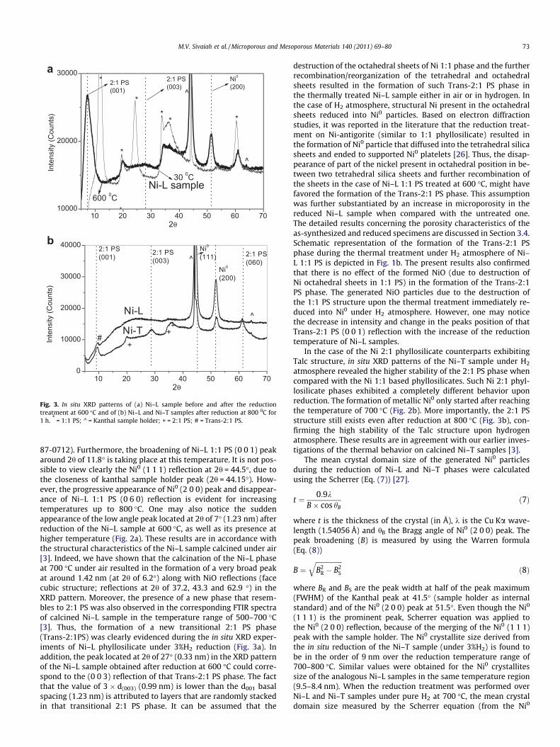
Fig. 3. In situ XRD patterns of (a) Ni–L sample before and after the reductiontreatment at 600 �C and of (b) Ni–L and Ni–T samples after reduction at 800 0C for1 h. * = 1:1 PS; ^ = Kanthal sample holder; + = 2:1 PS; # = Trans-2:1 PS.
M.V. Sivaiah et al. / Microporous and Mesoporous Materials 140 (2011) 69–80 73
87-0712). Furthermore, the broadening of Ni–L 1:1 PS (0 0 1) peakaround 2h of 11.8� is taking place at this temperature. It is not pos-sible to view clearly the Ni0 (1 1 1) reflection at 2h = 44.5�, due tothe closeness of kanthal sample holder peak (2h = 44.15�). How-ever, the progressive appearance of Ni0 (2 0 0) peak and disappear-ance of Ni–L 1:1 PS (0 6 0) reflection is evident for increasingtemperatures up to 800 �C. One may also notice the suddenappearance of the low angle peak located at 2h of 7� (1.23 nm) afterreduction of the Ni–L sample at 600 �C, as well as its presence athigher temperature (Fig. 2a). These results are in accordance withthe structural characteristics of the Ni–L sample calcined under air[3]. Indeed, we have shown that the calcination of the Ni–L phaseat 700 �C under air resulted in the formation of a very broad peakat around 1.42 nm (at 2h of 6.2�) along with NiO reflections (facecubic structure; reflections at 2h of 37.2, 43.3 and 62.9 �) in theXRD pattern. Moreover, the presence of a new phase that resem-bles to 2:1 PS was also observed in the corresponding FTIR spectraof calcined Ni–L sample in the temperature range of 500–700 �C[3]. Thus, the formation of a new transitional 2:1 PS phase(Trans-2:1PS) was clearly evidenced during the in situ XRD exper-iments of Ni–L phyllosilicate under 3%H2 reduction (Fig. 3a). Inaddition, the peak located at 2h of 27� (0.33 nm) in the XRD patternof the Ni–L sample obtained after reduction at 600 �C could corre-spond to the (0 0 3) reflection of that Trans-2:1 PS phase. The factthat the value of 3 � d(003) (0.99 nm) is lower than the d001 basalspacing (1.23 nm) is attributed to layers that are randomly stackedin that transitional 2:1 PS phase. It can be assumed that the
destruction of the octahedral sheets of Ni 1:1 phase and the furtherrecombination/reorganization of the tetrahedral and octahedralsheets resulted in the formation of such Trans-2:1 PS phase inthe thermally treated Ni–L sample either in air or in hydrogen. Inthe case of H2 atmosphere, structural Ni present in the octahedralsheets reduced into Ni0 particles. Based on electron diffractionstudies, it was reported in the literature that the reduction treat-ment on Ni-antigorite (similar to 1:1 phyllosilicate) resulted inthe formation of Ni0 particle that diffused into the tetrahedral silicasheets and ended to supported Ni0 platelets [26]. Thus, the disap-pearance of part of the nickel present in octahedral position in be-tween two tetrahedral silica sheets and further recombination ofthe sheets in the case of Ni–L 1:1 PS treated at 600 �C, might havefavored the formation of the Trans-2:1 PS phase. This assumptionwas further substantiated by an increase in microporosity in thereduced Ni–L sample when compared with the untreated one.The detailed results concerning the porosity characteristics of theas-synthesized and reduced specimens are discussed in Section 3.4.Schematic representation of the formation of the Trans-2:1 PSphase during the thermal treatment under H2 atmosphere of Ni–L 1:1 PS is depicted in Fig. 1b. The present results also confirmedthat there is no effect of the formed NiO (due to destruction ofNi octahedral sheets in 1:1 PS) in the formation of the Trans-2:1PS phase. The generated NiO particles due to the destruction ofthe 1:1 PS structure upon the thermal treatment immediately re-duced into Ni0 under H2 atmosphere. However, one may noticethe decrease in intensity and change in the peaks position of thatTrans-2:1 PS (0 0 1) reflection with the increase of the reductiontemperature of Ni–L samples.
In the case of the Ni 2:1 phyllosilicate counterparts exhibitingTalc structure, in situ XRD patterns of the Ni–T sample under H2
atmosphere revealed the higher stability of the 2:1 PS phase whencompared with the Ni 1:1 based phyllosilicates. Such Ni 2:1 phyl-losilicate phases exhibited a completely different behavior uponreduction. The formation of metallic Ni0 only started after reachingthe temperature of 700 �C (Fig. 2b). More importantly, the 2:1 PSstructure still exists even after reduction at 800 �C (Fig. 3b), con-firming the high stability of the Talc structure upon hydrogenatmosphere. These results are in agreement with our earlier inves-tigations of the thermal behavior on calcined Ni–T samples [3].
The mean crystal domain size of the generated Ni0 particlesduring the reduction of Ni–L and Ni–T phases were calculatedusing the Scherrer (Eq. (7)) [27].
t ¼ 0:9kB� cos hB
ð7Þ
where t is the thickness of the crystal (in Å), k is the Cu Ka wave-length (1.54056 Å) and hB the Bragg angle of Ni0 (2 0 0) peak. Thepeak broadening (B) is measured by using the Warren formula(Eq. (8))
B ¼ffiffiffiffiffiffiffiffiffiffiffiffiffiffiffiffiB2
R � B2S
qð8Þ
where BR and BS are the peak width at half of the peak maximum(FWHM) of the Kanthal peak at 41.5� (sample holder as internalstandard) and of the Ni0 (2 0 0) peak at 51.5�. Even though the Ni0
(1 1 1) is the prominent peak, Scherrer equation was applied tothe Ni0 (2 0 0) reflection, because of the merging of the Ni0 (1 1 1)peak with the sample holder. The Ni0 crystallite size derived fromthe in situ reduction of the Ni–T sample (under 3%H2) is found tobe in the order of 9 nm over the reduction temperature range of700–800 �C. Similar values were obtained for the Ni0 crystallitessize of the analogous Ni–L samples in the same temperature region(9.5–8.4 nm). When the reduction treatment was performed overNi–L and Ni–T samples under pure H2 at 700 �C, the mean crystaldomain size measured by the Scherrer equation (from the Ni0

74 M.V. Sivaiah et al. / Microporous and Mesoporous Materials 140 (2011) 69–80
(1 1 1) peak) were, respectively, of 7.4 and 6 nm [3]. The differencesin the Ni0 crystallite size of the Ni–L and Ni–T samples in both stud-ies logically result from the concentration of hydrogen used for thereduction treatment. Our data are corroborated by the results ob-tained by Burattin et.al [23], who showed that the particles size ofNi0 in Ni-based phyllosilicates was affected by the reduction treat-ment conditions, such as the flow and concentration of H2, as wellas the heating rate.
In summary, either starting from 1:1 or 2:1 Ni-containing phyl-losilicates, one can define the reduction parameters in order togenerate supported nanometric Ni0 particles over i) the remainingunreduced 2:1 PS structure (case of Talc PS structure), ii) over thethermally unstable Trans-2:1 PS phase in the case of 1:1 PS re-duced at T < 700 �C or iii) over amorphous silica when the reduc-tion of 1:1 PS at temperature >700 �C. The Ni0 dispersion wasdetermined from the mean crystal size domain values accordingto Eq. (9).
Dispersion;Dð%Þ ¼ 97:2=t ð9Þ
where t is the mean crystal size in nm. Ni0 dispersion values in therange of 11–17% were obtained on reduced Ni–L and N-T sample(Table 1). These values are in agreement with those of the Ni/sup-ported catalysts reported in the literature [7,11].
Fig. 4. Bright field TEM image of Ni–L sample (L–R3-800) after the reduction treatment adark-field TEM micrograph obtained from several reflections of the (1 1 1) ring (c), HRshowing the upper particle X given in Fig. 4d (e).
3.2. TEM of reduced Ni-based phyllosilicates
Supported Ni0 nanoparticles after reduction of the Ni–L and Ni–T phyllosilicates were evaluated by conventional and high resolu-tion TEM measurements (Figs. 4 and 5). The bright field TEM imageof Ni–L phyllosilicate reduced at 800 �C (L–R-800 sample) showeda high density of small circular or oval-shaped particles with size inthe range 5–20 nm (Fig. 4a). The corresponding selected area elec-tron diffraction (SAED) pattern illustrated a ring pattern that couldarise from very small, randomly oriented nickel crystallites. Eachconcentric ring in Fig. 4b corresponds to a particular set of (hkl)reflections, which are in agreement with the reflections of thefaced centered cubic Ni0 (JCPDS No. 87-0712). Thus, XRD resultsare in accordance with SAED patterns of the 1:1 Ni-based phyllosil-icates reduced at 800 �C (L–R-800 sample). The image shown inFig. 4c is a dark-field TEM micrograph obtained from the nickel(1 1 1) diffraction spots. High resolution phase contrast image ofthe reduced Ni–L sample after 800 �C under 3%H2 (L–R3-800 sam-ple) showed two sphere-shaped particles embedded within thematrix (Fig. 4d). Fast Fourier Transform (FFT) from the upper par-ticle in Fig. 4d indicated that the particle is twinned (as shownby the label M) with the {1 1 1} plane as twin boundary (Fig. 4e).The present TEM results on the reduced Ni–L sample are in
t 800 �C under 3%H2 (a), corresponding selected area electron diffraction pattern (b),TEM image of L–R3-800 sample (d) and Fast Fourier Transform (FFT) of the image

Fig. 5. TEM image of Ni–T sample reduced at 700 �C under pure hydrogen.
2
4
6
8
Qua
ntity
Ads
orbe
d (m
mol
/g)
Ni-T
Ni-L
a
M.V. Sivaiah et al. / Microporous and Mesoporous Materials 140 (2011) 69–80 75
agreement with the data reported by Dalmai-Imelik et al. [26].TEM and electron diffraction studies were carried out over nickelantigorite materials (similar to 1:1 PS) in order to characterizetheir morphology and structure after reduction at 700 �C [26].Complete extraction of structural Ni in such 1:1 PS phase was ob-served, resulting in Ni0 crystallites exhibiting their (1 1 1) planeperpendicular to the silica sheet [26].
By contrast to the micrograph of the reduced Ni 1:1 PS, the TEMimage of the Ni 2:1 PS phase reduced at 700 �C (T–R-700 sample)clearly showed the presence of an unreduced phyllosilicate struc-ture covered with highly uniformly formed and dispersed Ni0
nanoparticles (Fig. 5). The Ni0 particles size distribution of the re-duced Ni–L and Ni–T based phyllosilicates determined from TEMmicrographs is shown in Fig. 6. It is clearly observed that thereduction of Ni 2:1 PS phase (Ni–T sample) at 700 �C resulted inthe formation of smaller Ni particle (average diameter 7 nm) cou-pled to a narrow size distribution (4–11 nm) when compared withthe corresponding reduced Ni 1:1 PS phase (Ni–L sample). The low-er Ni content and the high thermal stability of the Ni-containing PSsample with Talc structure are responsible of the partial reductionof nickel, which results in the formation of an unreduced PS struc-ture acting as support for Ni0 particles. Smaller nanometric nickelparticles exhibiting a uniform size distribution are therefore gener-ated. In addition, for both reduced Ni-based PS phases, the particlessize determined from TEM experiments is close to the crystallitessize calculated from the XRD Ni0 (2 0 0) peak.
2 4 6 8 10 12 14 16 18 20 22 24 260
5
10
15
20
25
11 L-R3-800
T-R-700
%
Ni0 particle size, nm
7
Average particle size, nm
Fig. 6. Ni0 particles size distribution after the reduction treatment on Ni–L and Ni–Tsamples.
3.3. N2 isotherms of reduced and unreduced Ni-based PS
Typical N2 adsorption–desorption isotherms obtained for re-duced and unreduced Ni–L and Ni–T phyllosilicates are shown inFig. 7. The corresponding BET surface area and average pore diam-eter values are given in Table 1. The surface area of as-prepared Ni–L sample (147 m2 g�1) is found to be lower than the one exhibitedby the Ni-based PS with Talc structure (291 m2 g�1). Both Ni–L andNi–T N2 isotherms are closest in shape to type IV and seemed to becomposite of type IVa and type IVb isotherms as suggested byRouquerol and Sing [28]. Similar shapes of their hysteresis loopswere also observed. As-synthesized Ni–L and Ni–T samples dis-played H2 hysteresis behavior according to IUPAC classification.The average pore diameter was determined from the adsorptionbranch of the isotherm, which is most often reported for clays.Generally the pore size distributions from type IV isotherms arequite reliable, but for those with type H2 hysteresis loops, theadsorption branch is best used [28]. Because the adsorption iso-therms are broad in the case of the Ni 1:1 based PS (Lizardite struc-ture), the corresponding pore size distribution is also rather broad(not shown here). The mean pore diameter for Ni–L and Ni–T as-synthesized samples is found to be 7 and 4.1 nm, respectively.
As expected, upon reduction of Ni–L and Ni–T phyllosilicates,their surface area values decreased with the increase of the reduc-tion temperature, from 147 to 14 m2 g�1 and from 291 to160 m2 g�1, respectively (Table 1, Fig 7b). Such results can be ex-plained by the collapse of the 1:1 PS structure at high temperature.
0.0 0.2 0.4 0.6 0.8 1.00
Relative pressure (p/p°)
0.0 0.2 0.4 0.6 0.8 1.00
1
2
3
4
5
T-R3-800
Qua
ntity
Ads
orbe
d (m
mol
/g)
Relative Pressure (p/p°)
L-R-700
b
Fig. 7. N2 adsorption–desorption isotherms of (a) Ni–L and (b) Ni–T samples.

0
20
40
60
80
100
L-R-700 L-R3-700 L-R3-800
CH
4 Con
vers
ion,
%
300 350 400 450 500 550 600 650 700 750 800
0
20
40
60
80
100
L-R-700 L-R3-700 L-R3-800
CO
2 Con
vers
ion,
%
2
3
L-R-700 L-R3-700 L-R3-800
Temperature, 0C
300 350 400 450 500 550 600 650 700 750 800Temperature, 0C
a
b
c
76 M.V. Sivaiah et al. / Microporous and Mesoporous Materials 140 (2011) 69–80
By contrast, in the case of the thermally stable 2:1 PS phases, thepresence of mesoporosity in the T–R3-800 sample indicated thatunreduced 2:1 PS phase still exists even at high reduction temper-ature (Fig. 7b). Moreover, the mean pore diameter of the reducedT–R-700 (6 nm) and T–R3-800 (5 nm) samples was shown to beclose to its initial value (4.1 nm), thereby confirming the stabilityof the 2:1 phyllosilicate structure upon reduction, whatever theH2 concentration. N2 adsorption trend at low P/P0 region of re-duced Ni–T based PS indicated that the samples contained micro-porosity along with mesoporosity, as determined by the t-plotmethod (Figs. S1 and S2). Microporosity in 2:1 PS structure (suchas smectitic type clay minerals) is well known in the literature[29]. While almost no micropore volume was exhibited by theas-synthesized Ni–T sample due to the stacking of the interlayerspace, it is interesting to note an enhancement of microporosityin the reduced T–R3-800 specimen (2.6 � 10�2 cm3 g�1, Table 1and Fig. S1). Such amount of micropore volume in Ni–T after reduc-tion under 3%H2 at 800 �C is far higher than the value obtained forthe unreduced sample. A similar observation was also noticed forthe reduced Ni–L sample when compared with the as-synthesizedNi–L counterpart (Table 1 and Fig. S2). As mentioned earlier, reduc-tion treatment on Ni-antigorite (similar to 1:1 PS) led to the forma-tion of supported Ni0 particles due to extraction of the structural Nipresent in the octahedral sheets and further diffusion into the silicasheets [26]. Therefore, the delamination of Ni octahedral sheetsleaved a void/gap in between the two silica tetrahedral sheets.The observed enhancement of microporosity in reduced Ni–Lphase when compared with the unaltered PS structure may stemfrom the generated void/gap in between the silica sheets. Thisassumption was substantiated by the values of the micropore vol-ume obtained on Ni–L phyllosilicate thermally treated under airflow (1.5 � 10�2 cm3 g�1, Fig. S3). In that case, decomposition ofstructural Ni into NiO2 was observed. Thus, N2 adsorption–desorp-tion experiments supports the possible path for the formation of aTrans-2:1 PS phase in the case of Ni–L sample thermally treatedunder H2 atmosphere (Fig. 1b). However, the influence of the de-gree of crystallinity (or stacking of layers) of thermally treated PSphases on their porosity behavior can not be excluded, since itmay also account for the difference observed in the microporosityof treated and untreated PS phases.
All the characterization results of reduced and unreduced Ni–Land Ni–T phases are gathered in Table 1 and the data demonstratethat Ni0 nanoparticles can be easily obtained from the reduction ofboth 1:1 and 2:1 Ni-containing PS structures. Moreover, quite highNi0 dispersion values were observed for Ni–L and N-T PS phasesused as catalyst precursors (about 11–17% from XRD data).
3.4. Catalytic data
3.4.1. CO2 reforming of CH4
The reduction parameters for Ni–L (Ni 1:1 PS) and Ni–T (Ni 2:1PS) samples and their labels are gathered in Table 1. The CH4 and
Table 2Thermodynamic data of CO2 reforming of CH4 and possible parallel reactions duringreforming reaction.
Equation DG (kJ mol�1)a
300 �C 500 �C 800 �C
CH4 + CO2 ? 2CO + 2H2 99.37 41.58 �54.84CO + 3H2 ? CH4 + H2O �82.43 �32.06 55.41CO2 + 4H2 ? CH4 + 2H2O �65.50 �22.53 55.98H2 + CO2 ? CO + H2O 16.94 9.52 0.57C + CO2 ? 2CO 71.17 34.75 �20.88CH4 ? C + 2H2 28.20 6.83 �33.95
a The values were calculated from the data presented in [33].
CO2 conversion values obtained for the Ni–L and Ni–T phyllosili-cates as catalyst precursors during the temperature range of300–800 �C are shown in Fig. 8 and 9.
All the reduced samples evaluated for reforming reaction arecatalytically active. At low temperature (300–500 �C), the catalyticactivity was found to be very low, in accordance with the thermo-dynamic data (Table 2) for a mixture of CH4 and CO2 [30]. However,while a low CO2 conversion was observed in the temperature rangeof 300–400 �C, analysis of the reaction products indicated that CH4
was produced in the temperature region examined (conversion be-low zero in Fig. 8a). Such result can be explained by the methana-tion reactions of CO2 and CO according to the following equations:
300 400 500 600 700 8000.0
0.4
0.8
1.2
H2/C
O R
atio
Temperature, 0C
Fig. 8. CH4 conversion (a), CO2 conversion (b) and H2/CO ratios (c) as a function oftemperature obtained over reduced Ni–L catalysts (Ni 1:1 PS).

300 350 400 450 500 550 600 650 700 750 800
0
20
40
60
80
100
T-R-700 T-R3-800
CH
4 Con
vers
ion,
%
0
20
40
60
80
100
T-R-700 T-R3-800
CO
2 Con
vers
ion,
%
Temperature, 0C
300 350 400 450 500 550 600 650 700 750 800Temperature, 0C
a
b
c
Fig. 9. CH4 conversion (a), CO2 conversion (b) and H2/CO ratios (c) as a function oftemperature obtained over reduced Ni–T catalysts (Ni 2:1 PS).
M.V. Sivaiah et al. / Microporous and Mesoporous Materials 140 (2011) 69–80 77
COþ 3H2 ! CH4 þH2O ð10Þ
CO2 þ 4H2 ! CH4 þ 2H2O ð11Þ
Substantial CH4 conversion only started after reaching the reac-tion temperature of 500 �C and linearity in the CH4 conversion wasobserved only after 600 �C (Figs. 8a and 9a). Indeed, the thermody-namic data (free energy change at 300, 500 and 800 �C) gathered inTable 2 revealed that methanation reactions are favored at lowtemperature. However, the CO2 conversion obtained for all cata-lysts during the temperature range studied is higher than that of
CH4 (Figs. 8b and 9b), therefore suggesting the presence of parallelreactions such as the reverse water gas shift (Eq. (12)) and reverseBoudouard reactions (Eq. (13)) favored at high temperature.
H2 þ CO2 ! COþH2O ð12Þ
Cþ CO2 ! 2CO ð13Þ
Such higher CO2 conversion trend when compared with CH4 con-version can also be explained by the methanation (Eqs. (10) and(11)).
Slight differences in the conversion of CH4 and CO2 over reducedNi–L (1:1 PS) and Ni–T (2:1 PS) catalysts were observed, dependingon the reduction conditions (Figs. 8 and 9). In the case of reducedNi–L catalysts at 700 �C with pure or diluted H2, as well as at 800 �Cwith diluted H2 (L–R-700, L–R3-700 and L–R3-800 samples,respectively), both reduced with diluted hydrogen L–R3-700 andL–R3-800 catalysts showed a lower CH4 conversion when com-pared with that of L–R-700 sample. The lower CH4 conversion mostlikely stemmed from the lower amount of generated Ni0 particlesduring the reduction treatment with 3%H2. Marked differences inCO2 conversion were observed only at higher temperatures(700–800 �C) for Ni–L based catalysts. The conversion of CO2 forL–R3-700 sample after 700 �C was lower than that of L–R-700and L–R3-800 samples. As mentioned in the in situ XRD results(Section 3.1), the Trans-2:1 PS phase formed in the Ni 1:1 PS afterreduction at 600 �C, is not stable at high temperature (Fig. 2). Thus,the destruction of the Trans-2:1 PS structure of the reduced Ni 1:1PS at 700 �C with 3%H2 (L–R3-700 sample) occurred during thereforming reaction carried out at higher temperature (700–800 �C), thereby resulting in lower CO2 conversion. Similar resultswere observed during the stability experiments up to 12 h of reac-tion on reduced Ni–L catalysts whatever their degree of crystallin-ity [3]. In fact, 44% of the initial activity for CH4 conversion was lostwithin 12 h of reaction over reduced Ni–L catalyst (L–R-700),whereas only 4% of decreased activity was observed for the corre-sponding reduced Ni 2:1 PS catalyst (T–R-700 sample), resulting in34% and 51% of CH4 and CO2 conversion values, respectively for T–R-700 catalyst after 12 h of reaction [3].
Significant differences in CH4 conversion were obtained over Ni2:1 PS reduced with pure hydrogen (T–R-700 sample) or with 3%H2
(T–R3-800 sample), which can be ascribed to their difference in Ni0
crystallite size (Table 1). The CO2 conversion obtained over T–R-700 and T–R3-800 samples was almost similar during the temper-ature range of 600–800 �C. In both samples, the presence of aremaining unreduced phyllosilicate structure (along with silica)acting as support for Ni0 nanoparticles, led to similar CO2 conver-sion. The CO2 and CH4 conversion values obtained at 700 �C forall catalysts are shown in Table 1. According to the results obtainedfrom the in situ XRD and TEM characterization based on variablereduction conditions, our data confirm that CO2 conversion is sup-port dependent, whereas CH4 conversion is Ni0 particles size sensi-tive. In accordance with the present catalytic results, our firstinvestigation on the reforming reaction over hydrothermally syn-thesized Ni-containing 1:1 and 2:1 phyllosilicates as catalyst pre-cursors indicated that highly crystalline PS structures (Ni 2:1 PS)were found to be more stable and exhibited higher CO2 conversionthan the analogous poorly crystalline Ni 1:1 PS samples [3].
The selectivity of the catalysts towards CO and H2 formation isexpressed as H2/CO mole ratio and the corresponding values areshown in Fig. 8c and Fig. 9c. The H2/CO values obtained below500 �C varied between 1 and 3 for reduced Ni–L based catalysts(Fig. 8c) and between 2 and 5 for reduced Ni–T based catalysts,thereby indicating the existence of side reactions along with theCH4 reforming reaction. The negative balance of carbon in the tem-perature range of 300–500 �C can be explained by a carbon depo-sition according to the exothermic Boudouard reaction, thereby

300 400 500 600 700 800
0
10
20
30
40
50
60
70
L-R-700; H2
L-R-700; CO2
T-R-700; H2
T-R-700; CO2
H2
or C
O2 C
onve
rsio
n, %
Temperature, 0C
300 350 400 450 500 550 600 650 700 750 8000
10
20
30
40
50
60
70
80
90
100 L-R-700; CH4 Yield L-R-700; CO Yield T-R-700; CH4Yield T-R-700; CO Yield
CO
or C
H4 Y
ield
, %
Temperature, 0C
a
b
Fig. 10. H2 and CO2 conversions as a function of the temperature obtained over L–R-700 and T–R-700 samples (a) and CO and CH4 yield as a function of temperatureobtained during the RWGS reaction (b).
78 M.V. Sivaiah et al. / Microporous and Mesoporous Materials 140 (2011) 69–80
leading to an important CO consumption. In addition, part of H2
also reacts during the methanation reaction that occurs in thisrange of temperature as well. Therefore a combination of bothreactions (Boudouard predominantly and methanation to some ex-tent) results in a H2/CO ratio higher than 1. However, it is observedthat the RWGS reaction is also active during that temperaturerange examined. Indeed, large deviation in the H2/CO ratio valueswas observed below 500 �C for both reduced Ni–L and Ni–T cata-lysts when compared with the theoretical value of 1. At 600 �C,Ni–L based catalysts showed a H2/CO ratio about 0.8 and this valuewas maintained up to 800 �C for L–R-700 and L–R3-800 catalysts.By contrast, the reduced Ni–L catalyst with diluted hydrogen (L–R3-700) led to a H2/CO ratio up to 1.2 during the temperaturerange of 700–800 �C. This can be explained by the decreased CO2
conversion activity exhibited by the L–R3-700 catalyst, therebygiving lower CO values during the temperature range of 700–800 �C. H2/CO ratios slightly increased from �0.8 to 0.9 with the in-crease of temperature from 600 to 800 �C for reduced Ni–Tcatalysts.
Thus, the catalytic behavior of both reduced Ni–L and Ni–Tphyllosilicates can be generalized as follows: (a) in the tempera-ture range of 300–500 �C, only CO2 conversion was observed withthe formation of CH4 (instead of conversion). Such methane forma-tion during the reforming reaction can be due to the CO/CO2 hydro-genation reaction; (b) in the 550–800 �C region, a linear increase ofCH4 and CO2 conversions was shown with increasing tempera-tures; c) more importantly CO2 conversion was observed in thesame temperature range and the resulting H2/CO mole ratio wasshown to be constant (<1 except for L–R3-700 sample). Thus, thepresence of RWGS and Boudouard reactions along with the reform-ing reaction is inevitable for both reduced 1:1 and 2:1 Ni-basedphyllosilicate catalysts.
3.4.2. Reverse water gas shift (RWGS) reactionIn order to know the role of RWGS reaction on the methane
reforming reaction, the catalysts were evaluated under identicalconditions (of reforming reaction) while passing the H2 and CO2
mixture with a 1:1 feed ratio and total flow rate of 100 mL min�1.The catalytic conversion values of H2 and CO2 obtained during thetemperature range of 300–800 �C are gathered in Fig. 10a and theresulting yield to CO and CH4 during the reaction is shown inFig. 10b. It is interesting to note that there are three regions ofH2 and CO2 conversion during the temperature range of 300–450 �C, 450–650 �C and 650–800 �C. There is a steep increase ofH2 conversion up to 70% during the temperature range of 300–450 �C, whereas CO2 conversion reaches 25% only. From 450 to650 �C, a sharp decrease in H2 conversion from 70% to 45% is ob-served, while that of CO2 is gradually raised up to 45%. After650 �C, a gradual increase of both H2 and CO2 conversion is noticedup to around 55%.
The CO and CH4 yield obtained over L–R-700 and T–R-700 cat-alyst samples suggested that methanation reactions were predom-inant up to 450 �C and that the production of CH4 decreased withthe increase of temperature (at 650 �C the CH4 yield was closedto zero). Above 600 �C, only CO yield was observed and this valuereached 75% at 700 �C. The present CO and CH4 yield trend overboth catalysts is in agreement with the results of the RWGS reac-tion carried out over Ni/CeO2 catalysts [31]. In fact, methanationof CO or CO2 over such Ni supported catalysts was reported. Inour study, the yield to CH4 on L–R-700 catalyst is higher than theone of T–R-700 sample. It was reported in the literature that highamount of supported Ni on CeO2 led to agglomeration of Ni0, there-by resulting in high CH4 yield [31]. By contrast, highly dispersed Niparticles (along with oxygen vacancies) in co-precipitated Ni–CeO2
were shown to be the key active components for RWGS. Such re-sults pointed out that bulk Ni particles are the main active sites
for methanation of CO2 [31]. As observed from TEM analysis, theagglomeration/sintering of Ni0 were noticed in the case of the re-duced Ni–L catalyst (L–R3-800 sample). Nearly total reduction ofthe high Ni content of Ni–L sample (46% of Ni) resulted in Ni0 par-ticles supported on silica (due to the destruction of the phyllosili-cate structure during the reduction process), which is the reasonfor Ni0 agglomeration in L–R3-800 sample, when compared withpartially reducible lower content Ni–T sample (with 36% of Ni).Thus, both methanation (Eqs. (10) and (11)) and RWGS (Eq. (12))reactions may occur during the temperature range of 300–600 �C.Above 600 �C, only RWGS is the predominant reaction on bothreduced Ni–L and Ni–T catalysts.
3.4.3. TG–MS data on spent catalystsDuring the reaction of carbon dioxide reforming of methane, a
carbon deposition may occur according to the Boudouard (Eq.(12)) and methane cracking reactions (Eq. (1)). At 700 �C, the car-bon deposition can proceed by both reactions (DG� < 0; seeTable 2).
The amount of coke deposition was found to be �1% and 22%,respectively, for spent T–R-700 and L–R-700 catalysts after 12 hof reforming reaction at 700 �C [3]. TG–MS analyses were per-formed on such spent T–R-700 and L–R-700 catalysts in order to

100 200 300 400 500 600 700 800 900
0
5
10
15
20
Temperature, °C
CO
2 , io
n cu
rrent
(nA)
L-R-700
T-R-700
Fig. 11. TG–MS spectra of spent L–R-700 and T–R-700 catalysts after 12 h ofreaction at 700 �C.
M.V. Sivaiah et al. / Microporous and Mesoporous Materials 140 (2011) 69–80 79
investigate the temperature at which the carbon deposit can beburnt. TG–MS analyses indicated that CO2 gas evolved at around450–700 �C for spent L–R-700 catalyst, whereas less amount ofgenerated CO2 was observed for the counterpart spent T–R-700catalyst at around 350 �C and 600 �C (Fig. 11). Such results are inagreement with the TG weight losses that we previously reportedon spent L–R-700 and T–R-700 catalysts [3].
It was earlier suggested that there is a relationship between theoxidation temperature during thermogravimetric analysis and thelocation of carbon deposits both on the support and on Ni0 parti-cles [12]. Coke deposited on Ni0 particles was shown to burn at alower temperature than did the coke on the support. Similar re-sults are obtained on our side. Indeed, carbon growth was hardlyobserved on partially reduced Ni 2:1 PS phase (T–R-700 sample),while a high amount of coke deposit was obtained for the reducedNi 1:1 PS sample (L–R-700) that exhibit larger Ni0 particles sup-ported on silica only. In the case of the T–R-700 catalyst, Ni0 sup-ported on the remaining unreduced phyllosilicate structure wasshown to prevent the coke formation, due to the presence of highamount of superficial OH groups. Such hydroxyl groups wereshown to decrease the possibility of CHx scission into surfacecarbon species [32].
4. Conclusions
Our study demonstrated that homogeneously sized and dis-persed Ni0 nanoparticles were easily generated from hydrother-mally synthesized Ni-containing 2:1 phyllosilicates (Ni–Tsamples) by H2 reduction. Such Ni-based 2:1 PS phases provedthermally stable. After reduction at 700 �C, the remaining unre-duced phyllosilicate structure with surface hydroxyl groups actsas support for nanometric Ni0 particles (7–9 nm on average). Bycontrast, the reduction conditions, such as H2 concentration andtemperature, were shown to alter both the Ni0 particles size andthe nature of their support in the case of Ni-containing 1:1 phyllos-ilicate (Ni–L samples). The reduction below 700 �C of Ni 1:1 PS ledto silica and to a Transitional 2:1 PS structure as supports for Ni0
particles. Such Trans 2:1 PS phase was unstable at higher temper-ature, thereby leading to SiO2 as sole support for metallic nickelparticles. The resulting Ni0 particles size is in the range of 5–20 nm. Conventional and high resolution TEM analysis on reducedcatalysts revealed that the nanocrystallites of Ni0 were randomlyoriented. A significant decrease of specific surface areas for bothNi–L and Ni–T samples was observed after the reduction treatmentat 700 �C. However, the reduced Ni 2:1 PS phases (with Talc
structure) still exhibited about 150 m2 g�1. A far increase in micro-porosity for reduced Ni–L and Ni–T samples was also observedafter the reduction treatment.
The reduced Ni 1:1 and Ni 2:1 based phyllosilicates were usedas catalysts for the carbon dioxide reforming of methane. Slightdifferences in the conversion of CH4 and CO2 over reduced Ni–L(1:1 PS) and Ni–T (2:1 PS) catalysts were observed, depending onthe reduction conditions (H2 concentration and/or temperature).Our results suggest that CH4 conversion is dependent on the Ni0
particles size and that CO2 conversion is support sensitive (sole sil-ica or unreduced 2:1 PS structure). Highly dispersed nanometricNi0 particles over the remaining unreduced 2:1 PS structure arethe key active components for high catalytic activity in CO2
reforming of CH4.Reduced Ni–L and Ni–T catalysts were found to be also active
for RWGS reaction during the temperature range of 300–800 �C.Based on the CO and CH4 yield obtained during the reverse watergas shift reaction, it was shown that the methanation reaction(predominant for T < 450 �C) and RWGS (predominant forT > 600 �C) are parallel sides reactions due to CO and CO2 hydroge-nation during the CO2 reforming of CH4. Moreover, CH4 decompo-sition into H2, as well as Boudouard reaction, are also considered tobe the side reactions for CO2 reforming of CH4 over reduced Ni-containing 1:1 and 2:1 phyllosilicates.
Acknowledgements
The author (M.V.S.) gratefully acknowledges CNRS and Univer-sity of Poitiers for the awarding of postdoctoral fellowship.
Appendix A. Supplementary data
Supplementary data associated with this article can be found, inthe online version, at doi:10.1016/j.micromeso.2010.09.015.
References
[1] S.W. Bailey, in: S.W. Bailey (Ed.), Hydrous Phyllosilicates (Exclusive of Micas),Reviews in Mineralogy 19, Mineralogical Society of America, Washington, DC,2006, pp. 9–27.
[2] M.F. Brigatti, E. Galan, B.K.G. Theng, in: F. Bergaya, B.K.G. Theng, G. Lagaly(Eds.), Handbook of Clay Science, Developments in Clay Science, vol. 1, Elsevier,Amsterdam, 2006, pp. 19–86.
[3] M.V. Sivaiah, S. Petit, J. Barrault, C. Batiot-Dupeyrat, S. Valange, Catal. Today,2010, in press, doi:10.1016/j.cattod.2010.04.042.
[4] M.C.J. Bradford, M.A. Vannice, Catal. Rev. Sci. Eng. 41 (1999) 1–42.[5] E. Ruckenstein, Y.H. Hu, Adv. Catal. 48 (2004) 297–345.[6] S.C. Tsang, J.B. Claridge, M.L.H. Green, Catal. Today 23 (1995) 3–15.[7] G.S. Gallego, F. Mondragón, J. Barrault, J.-M. Tatibouët, C. Batiot-Dupeyrat,
Appl. Catal. A 311 (2006) 164–171.[8] M. García-Diéguez, I.S. Pieta, M.C. Herrera, M.A. Larrubia, L.J. Alemany, J. Catal.
270 (2010) 135–136.[9] B.S. Barros, D.M.A. Melo, S. Libs, A. Kiennemann, Appl. Catal. A 378 (2010) 69–
75.[10] G. Valderrama, A. Kiennemann, M.R. Goldwasser, J. Power Sources 195 (2010)
1765–1771.[11] T. Osaki, T. Horiuchi, K. Suzuki, T. Mori, J. Chem. Soc. Faraday Trans. 92 (1996)
1627–1631.[12] Y.-X. Pan, C.-J. Liu, P. Shi, J. Power Sources 176 (2008) 46–53.[13] V.C.H. Kroll, H.M. Swaan, C. Mirodatos, J. Catal. 161 (1996) 409–422.[14] S. Tomiyama, R. Takahashi, S. Sato, T. Sodesawa, S. Yoshida, Appl. Catal. A 53
(2003) 349–361.[15] A. Moronta, N. Iwasa, S.-I. Fujita, M. Shimokawabe, M. Arai, Clay Clay Mineral.
53 (2005) 622–630.[16] K. Tomishige, Y. Chen, O. Yamazaki, Y. Himeno, Y. Koganezawa, K. Fujjimoto,
Stud. Surf. Sci. Catal. 119 (1998) 861–866.[17] T. Horiuchi, K. Sakuma, T. Fukui, Y. Kubo, T. Osaki, T. Mori, Appl. Catal. A 144
(1996) 111–120.[18] S.B. Wang, G.Q.M. Lu, Energy Fuels 12 (1998) 248–256.[19] S. Corthals, J. Van Nederkassel, J. Geboers, H. De Winne, J. Van Noyen, B. Moens,
B. Sels, P. Jacobs, Catal. Today 138 (2008) 28–32.[20] S. Corthals, T. Witvrouwen, P. Jacobs, B. Sels, in press, 2010, doi:10.1016/
j.cattod.2010.06.021.

80 M.V. Sivaiah et al. / Microporous and Mesoporous Materials 140 (2011) 69–80
[21] S. Damyanova, B. Pawelec, K. Arishtirova, M.V. Martinez Huerta, J.L.G. Fierro,Appl. Catal. B 89 (2009) 149–159.
[22] M. Che, Z.X. Cheng, C. Louis, J. Am. Chem. Soc. 117 (1995) 2008–2018.[23] P. Burattin, M. Che, C. Louis, J. Phys. Chem. B 103 (1999) 6171–6178.[24] J.W.E. Coenen, Appl. Catal. 15 (1989) 65–78.[25] O. Clause, M. Kermarec, L. Bonneviot, F. Villain, M. Che, J. Am. Chem. Soc. 114
(1992) 4709–4717.[26] G. Dalmai-Imelik, C. Leclercq, A. Maubert-Muguet, J. Solid State Chem. 16
(1976) 129–139.[27] A.R. West (Ed.), Solid state chemistry and its applications, Wiley, New York,
1985.
[28] J. Rouquerol, F. Rouquerol, K. Sing (Eds.), Adsorption by Powders and PorousSolids, Academic Press, 1999.
[29] L.A.G. Aylmore, Clay Clay Mineral. 25 (1977) 148–154.[30] P. Ferreira-Aparicio, I.R. Ramos, A.G. Ruiz, Appl. Catal. A 237 (2002) 239–
252.[31] W. Luhui, Z. Shaoxing, L. Yuan, J. Rare Earths 26 (2008) 66–70.[32] S.-G. Wang, D.-B. Cao, Y.-W. Li, J. Wang, H. Jiao, Surf. Sci. 603 (2009) 2600–
2606.[33] D.R. Stull, E.F. Westrum, G.C. Sinke, The Chemical Thermodynamics of Organic
Compounds, John Wiley and Sons, New York, 1969.
Related Documents