NICFPS INSTRUMENT CONTROL SOFTWARE MANUAL Revision F Stéphane Béland University of Colorado at Boulder Center for Astrophysics & Space Astronomy Campus Box 593 Boulder, Colorado 80309 http://casa.colorado.edu

Welcome message from author
This document is posted to help you gain knowledge. Please leave a comment to let me know what you think about it! Share it to your friends and learn new things together.
Transcript

NICFPS INSTRUMENT CONTROL SOFTWARE MANUAL
Revision F
Stéphane Béland
University of Colorado at Boulder Center for Astrophysics & Space Astronomy
Campus Box 593 Boulder, Colorado 80309 http://casa.colorado.edu

REVISIONS Letter ECO No. Description Check Approved Date
Initial Release 08/18/04
A 09/01/04 B 09/02/04 C FP syntax change 09/10/04 D Added commands for EXPOSE 10/18/04 E Added PRESSURE and various status 11/11/04 F New filter operations, slit and Fowler 11/01/05
Original Release THE UNIVERSITY OF COLORADO Name Date At Boulder
Drawn: The Center for Astrophysics and Space Astronomy Reviewed: Approved: NICFPS Instrument Control Software
Size Code Indent No. Document No. Rev
A E Scale: N/A
NICFPS SW-001 11/4/05 Center for Astrophysics & Space Astronomy Rev E
NICFPS Instrument Control Software Manual University of Colorado at Boulder Page i
Table of Contents
1. Scope ....................................................................................................................... 1 2. Instrument and Devices Overview ............................................................................ 1
2.1 Terminal server and serial devices interface........................................................ 3 2.2 Temperature monitor .......................................................................................... 5 2.3 Stepper motors.................................................................................................... 5 2.4 Fabry-Pérot Etalon and controller ....................................................................... 6 2.5 H1RG Control and Acquisition........................................................................... 6
3. Instrument Control Software (ICS) Commands......................................................... 6 3.1 Command Syntax Definition............................................................................... 7 3.2 Commanding NICFPS ........................................................................................ 8 3.3 Commanding the Temperature Monitor .............................................................. 8 3.4 The Pressure Monitor ....................................................................................... 10 3.5 The Slit Mechanism.......................................................................................... 12 3.6 Commanding the Filter Wheels......................................................................... 13 3.7 Commanding the Fabry-Pérot Etalon ................................................................ 17
3.7.1 Linear Stage............................................................................................... 18 3.7.2 CS-100 Controller...................................................................................... 18
3.8 The Window Command.................................................................................... 21 3.9 The Fowler Sampling Command ...................................................................... 22 3.10 The Expose Command.................................................................................... 23
4. Exposure Time Determination................................................................................ 25 5. FITS Format and Keywords.................................................................................... 26
NICFPS SW-001 11/4/05 Center for Astrophysics & Space Astronomy Rev E
NICFPS Instrument Control Software Manual University of Colorado at Boulder Page 1
1. SCOPE
The purpose of the Instrument Control Software Manual is to define and document the requirements for the control software interface to the NIC-FPS instrument and its different devices. This document is bound to evolve as the system gets implemented and integrated with the other systems at the Astronomical Research Consortium (ARC) 3.5m telescope at Apache Point Observatory (APO).
2. INSTRUMENT AND DEVICES OVERVIEW
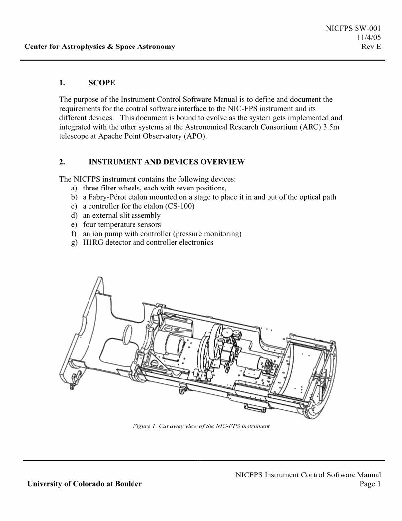
The NICFPS instrument contains the following devices: a) three filter wheels, each with seven positions, b) a Fabry-Pérot etalon mounted on a stage to place it in and out of the optical path c) a controller for the etalon (CS-100) d) an external slit assembly e) four temperature sensors f) an ion pump with controller (pressure monitoring) g) H1RG detector and controller electronics
Figure 1. Cut away view of the NIC-FPS instrument

NICFPS SW-001 11/4/05 Center for Astrophysics & Space Astronomy Rev E
NICFPS Instrument Control Software Manual University of Colorado at Boulder Page 2
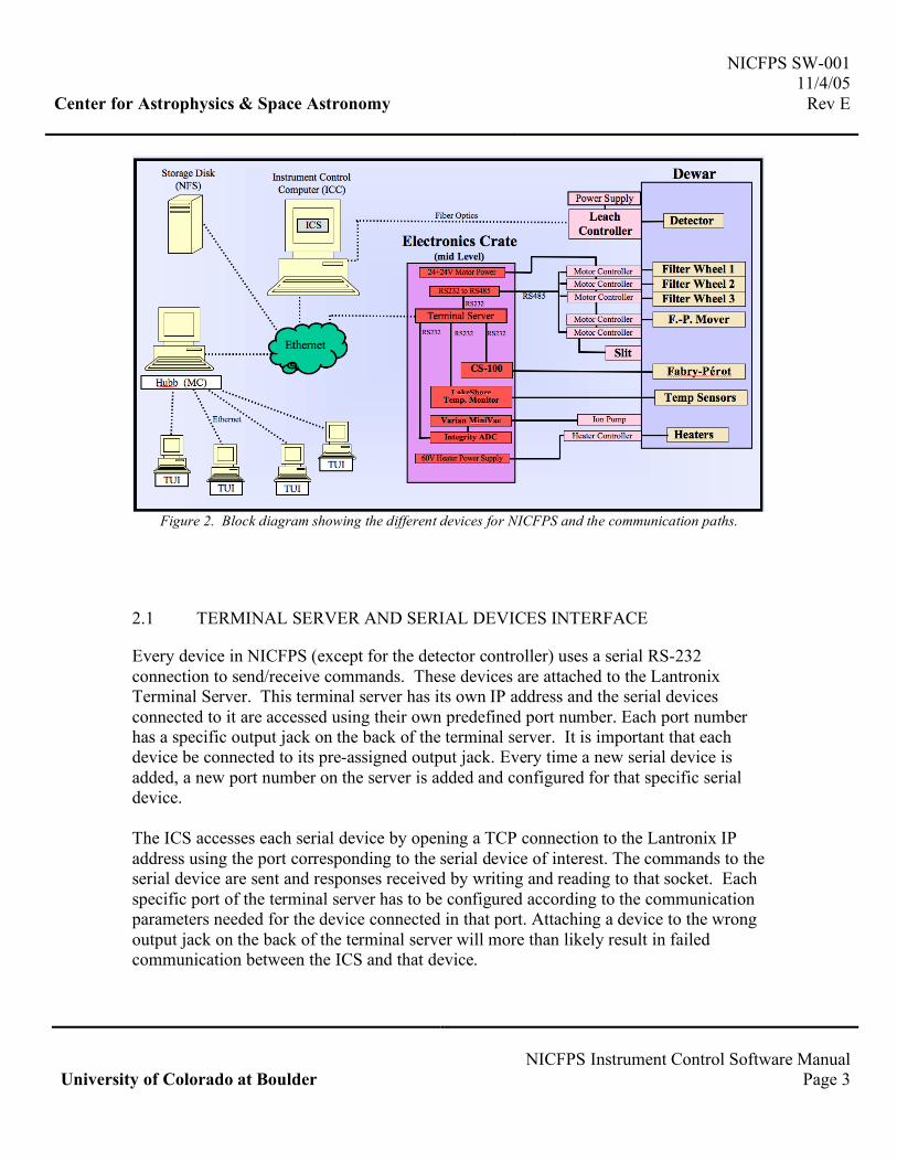
Identical motors from Portescap (P532-258-012.84) are used to move the filter wheels, slit and etalon in and out of the beam. The filter wheels and etalon motors are retro-fitted to work at 77˚K following the method described by Thomas O’brian at Ohio State University. The stepper motors are driven using the API Stepper Motor Controllers DM224i via an RS232 interface. A set of 2 redundant micro switches per filter wheel identifies the wheel’s “HOME”. The etalon mover uses four switches to identify the IN/OUT positions and allow redundancy. The temperature sensors consist of Platinum RTD and are connected to a Lakeshore monitor 218E which can be queried via an RS232 interface. The pressure is monitored by reading the voltage from the Varian’s MiniVac Ion Pump Controller. This voltage is proportional to the current flowing in the ion pump, which is proportional to the pressure. An Integrity Instrument RS232 analog and digital I/O module is used to read the pressure. Previously, a cold cathode pressure gauge was also used. This gauge is no longer in use but the ICS still contains the software to command and query it in case of future changes. The H1RG detector is connected directly to the Leach controller, which is attached to a PCI card inside of the Instrument Control Computer (ICC). Commands from the computer to the detector are sent through the PCI card to the controller via fiber-optic cable, and then to the detector itself. The Instrument Control Software (ICS) is the low level layer between the instrument/devices and the user (fig 1). The users run a copy of the Telescope User Interface (TUI), which talks to the HUB at APO via the Ethernet. The TUI contains a specific window for each instrument from which the users can command and control that specific instrument. One of the HUB responsibilities is to accept commands from the TUIs, and direct them to the corresponding instrument through an opened socket. The instrument receives the command, executes it and returns a response to the HUB. The response is then broadcasted to all of the connected TUI. This allows every TUI to get a status update for a specific device/instrument even if the request came from a different TUI.
NICFPS SW-001 11/4/05 Center for Astrophysics & Space Astronomy Rev E
NICFPS Instrument Control Software Manual University of Colorado at Boulder Page 3
Figure 2. Block diagram showing the different devices for NICFPS and the communication paths.
2.1 TERMINAL SERVER AND SERIAL DEVICES INTERFACE
Every device in NICFPS (except for the detector controller) uses a serial RS-232 connection to send/receive commands. These devices are attached to the Lantronix Terminal Server. This terminal server has its own IP address and the serial devices connected to it are accessed using their own predefined port number. Each port number has a specific output jack on the back of the terminal server. It is important that each device be connected to its pre-assigned output jack. Every time a new serial device is added, a new port number on the server is added and configured for that specific serial device. The ICS accesses each serial device by opening a TCP connection to the Lantronix IP address using the port corresponding to the serial device of interest. The commands to the serial device are sent and responses received by writing and reading to that socket. Each specific port of the terminal server has to be configured according to the communication parameters needed for the device connected in that port. Attaching a device to the wrong output jack on the back of the terminal server will more than likely result in failed communication between the ICS and that device.
NICFPS SW-001 11/4/05 Center for Astrophysics & Space Astronomy Rev E
NICFPS Instrument Control Software Manual University of Colorado at Boulder Page 4
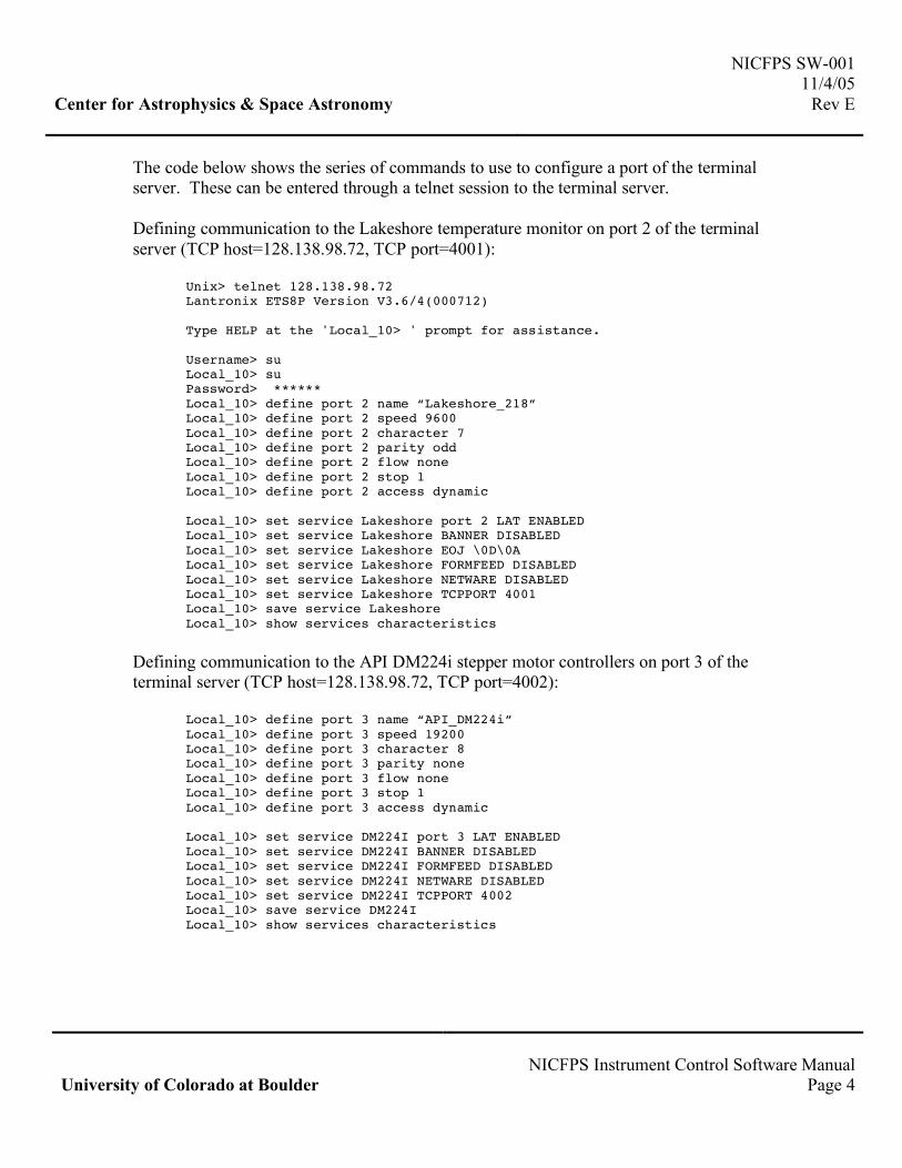
The code below shows the series of commands to use to configure a port of the terminal server. These can be entered through a telnet session to the terminal server. Defining communication to the Lakeshore temperature monitor on port 2 of the terminal server (TCP host=128.138.98.72, TCP port=4001):
Unix> telnet 128.138.98.72 Lantronix ETS8P Version V3.6/4(000712) Type HELP at the 'Local_10> ' prompt for assistance. Username> su Local_10> su Password> ****** Local_10> define port 2 name “Lakeshore_218” Local_10> define port 2 speed 9600 Local_10> define port 2 character 7 Local_10> define port 2 parity odd Local_10> define port 2 flow none Local_10> define port 2 stop 1 Local_10> define port 2 access dynamic Local_10> set service Lakeshore port 2 LAT ENABLED Local_10> set service Lakeshore BANNER DISABLED Local_10> set service Lakeshore EOJ \0D\0A Local_10> set service Lakeshore FORMFEED DISABLED Local_10> set service Lakeshore NETWARE DISABLED Local_10> set service Lakeshore TCPPORT 4001 Local_10> save service Lakeshore Local_10> show services characteristics
Defining communication to the API DM224i stepper motor controllers on port 3 of the terminal server (TCP host=128.138.98.72, TCP port=4002):
Local_10> define port 3 name “API_DM224i” Local_10> define port 3 speed 19200 Local_10> define port 3 character 8 Local_10> define port 3 parity none Local_10> define port 3 flow none Local_10> define port 3 stop 1 Local_10> define port 3 access dynamic Local_10> set service DM224I port 3 LAT ENABLED Local_10> set service DM224I BANNER DISABLED Local_10> set service DM224I FORMFEED DISABLED Local_10> set service DM224I NETWARE DISABLED Local_10> set service DM224I TCPPORT 4002 Local_10> save service DM224I Local_10> show services characteristics
NICFPS SW-001 11/4/05 Center for Astrophysics & Space Astronomy Rev E
NICFPS Instrument Control Software Manual University of Colorado at Boulder Page 5
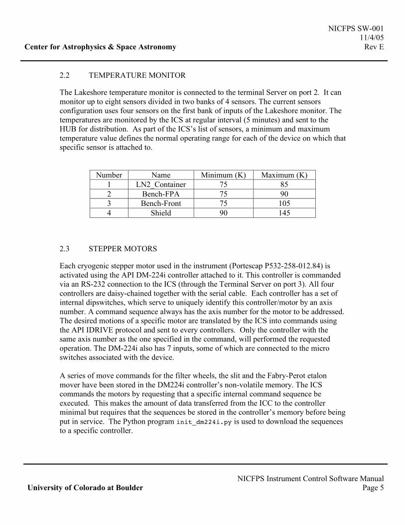
2.2 TEMPERATURE MONITOR
The Lakeshore temperature monitor is connected to the terminal Server on port 2. It can monitor up to eight sensors divided in two banks of 4 sensors. The current sensors configuration uses four sensors on the first bank of inputs of the Lakeshore monitor. The temperatures are monitored by the ICS at regular interval (5 minutes) and sent to the HUB for distribution. As part of the ICS’s list of sensors, a minimum and maximum temperature value defines the normal operating range for each of the device on which that specific sensor is attached to.
Number Name Minimum (K) Maximum (K) 1 LN2_Container 75 85 2 Bench-FPA 75 90 3 Bench-Front 75 105 4 Shield 90 145
2.3 STEPPER MOTORS
Each cryogenic stepper motor used in the instrument (Portescap P532-258-012.84) is activated using the API DM-224i controller attached to it. This controller is commanded via an RS-232 connection to the ICS (through the Terminal Server on port 3). All four controllers are daisy-chained together with the serial cable. Each controller has a set of internal dipswitches, which serve to uniquely identify this controller/motor by an axis number. A command sequence always has the axis number for the motor to be addressed. The desired motions of a specific motor are translated by the ICS into commands using the API IDRIVE protocol and sent to every controllers. Only the controller with the same axis number as the one specified in the command, will performed the requested operation. The DM-224i also has 7 inputs, some of which are connected to the micro switches associated with the device. A series of move commands for the filter wheels, the slit and the Fabry-Perot etalon mover have been stored in the DM224i controller’s non-volatile memory. The ICS commands the motors by requesting that a specific internal command sequence be executed. This makes the amount of data transferred from the ICC to the controller minimal but requires that the sequences be stored in the controller’s memory before being put in service. The Python program init_dm224i.py is used to download the sequences to a specific controller.

NICFPS SW-001 11/4/05 Center for Astrophysics & Space Astronomy Rev E
NICFPS Instrument Control Software Manual University of Colorado at Boulder Page 6
Details of the DM224i can be found in the “API Controls DM-224i and DM-225i Installation Users Guide” document. Details on the communication and commanding protocol can be found in the document “IDRIVE Protocol Specification Revision 0.5”. Most the API commands have been implemented in the Python program IDrive.py that is part of the ICS.
2.4 FABRY-PÉROT ETALON AND CONTROLLER
The parallelism and spacing of the Fabry-Pérot etalon is controlled by the CS-100. The CS-100 RS232 interface is attached to the Terminal Server (on port 3) and commands are received from the ICS using the specific port reserved for the CS-100. The ICS can command the spacing of the X, Y and Z-axis independently of each other. The details on the commanding protocol can be found in the “CS-100 Controller and ET Series II Servo-stabilized Interferometer System – User’s Guide”. The etalon is moved in and out of the optical path by commanding the corresponding motor to run the pre-defined internal sequence. The sequence moves the motor in the correct direction until the slide assembly reaches the position where the In or Out micro switch is triggered indicating the end of travel.
2.5 H1RG CONTROL AND ACQUISITION
The Leach controller from Astronomical Research Cameras includes a PCI card installed in the ICC. The ICS talks to the PCI card with the use of the Voodoo Application Programming Interface (API) and the Device Drivers provided with the Leach controller. Detailed description of the API can be found in the document “Voodoo and Device Driver Programmer’s Reference Manual”. Examples on how to use the API are distributed with the Voodoo software, which is part of the Leach controller package.
3. INSTRUMENT CONTROL SOFTWARE (ICS) COMMANDS
The Instrument Control Software (ICS) is written in Python and provides translation from the high level commands from the HUB, into commands the various devices that make up the instrument can understand. The ICS is expected to be running on the ICC before the HUB tries to connect to it. The following sections describe the command sets and the corresponding responses of the ICS for the different devices. Note that the TUI window specific to NICFPS only implements a subset of the commands described below. It is sometimes useful to run the additional commands for engineering or debugging purposes.
NICFPS SW-001 11/4/05 Center for Astrophysics & Space Astronomy Rev E
NICFPS Instrument Control Software Manual University of Colorado at Boulder Page 7
This can be done by manually typing the command and arguments in the TUI-Log window.
3.1 COMMAND SYNTAX DEFINITION
Commands are sent to the HUB by the user’s TUI, which then determines which instrument to forward the command string to. The commands to the NICFPS ICS are not case sensitive. The syntax from the TUI to the HUB is defined as:
<tid> <actor> <command><eol> Where: TID is a positive integer generated by the TUI to identify
the command ACTOR is the name of the instrument to command
COMMAND is any valid command string EOL is the end of line character (\n or Return character) (ex: “72 nicfps temps read\n”) The HUB passes the CMD to the instrument with the format:
<cid> <hid> <command><eol> Where: CID is the connection ID
HID is a positive integer generated by the HUB to identify the command COMMAND is any valid command string
EOL is the end of line character (\n or Return character) (ex: “4 72 temps read\n”) The actor (instrument’s ICS) receives the command, validates it, performs the command and returns a response to the HUB in the following format:
<cid> <hid> <flag> <key><eol> Where: CID is the connection ID
HID is a positive integer generated by the HUB to identify the command
FLAG is a “:” for successful processing of the command, “i” for intermediate response (more lines coming) “w” indication a warning “f” indicating a failure.
KEY can be any of the following: KEY KEY1;KEY2;… KEY=VAL KEY=VAL1,VAL2,… KEY=”a string” a combination of the above.
EOL is the end of line character (\n or Return character) (ex: “4 72 : TEMP=80.2,85.7,93.3\n”)
NICFPS SW-001 11/4/05 Center for Astrophysics & Space Astronomy Rev E
NICFPS Instrument Control Software Manual University of Colorado at Boulder Page 8
The HUB receives the response from the actor and broadcasts it to the TUIs as:
<cmdsrc> <tid> <actor> <flag> <key><eol> Where: CMDSRC is the name of the source of the command (which TUI)
TID is a positive integer generated by the TUI to identify the command
ACTOR is the name of the instrument the response came from FLAG is a “:” for successful processing of the command,
“i” for intermediate response (more lines coming) “w” indication a warning “f” indicating a failure.
KEY can be any of the following: KEY KEY1;KEY2;… KEY=VAL KEY=VAL1,VAL2,… KEY=”a string” a combination of the above.
EOL is the end of line character (\n or Return character)
3.2 COMMANDING NICFPS
Two commands are available at the instrument level: help and status. Valid Commands: “nicfps help” - prints the list of valid ICS commands “nicfps status” - runs the “status” command for every devices to
get the current global status of the instrument. The HUB mainly uses this command when it first connects to the ICS.
3.3 COMMANDING THE TEMPERATURE MONITOR
The temperature is monitored at regular interval (every 5 minutes) by the ICS. Valid operating ranges are defined and whenever a sensor is found to be outside of this range, the ICS will send warning to the HUB to be broadcasted to all TUIs. The users, through the TUI, are also able to query the temperatures at any time. The ICS sends the current temperatures and possibly a warning to the HUB at regular interval in the following format:

NICFPS SW-001 11/4/05 Center for Astrophysics & Space Astronomy Rev E
NICFPS Instrument Control Software Manual University of Colorado at Boulder Page 9
: TEMP=value1,value2,value3,value4,… w TEMP_WARN=”sensor_name1 is too hot!” w TEMP_WARN=”sensor_name2 is too cold!” CID 0 FLAG KEY Where: CID is the connection ID ID is now 0 (zero) indicating unsolicited responses
FLAG is a w” indication a warning KEY is TEMP_SensorName_WARN=current_temp,min_temp,max_temp
EOL is the end of line character (\n or Return character) (ex: “4 0 : TEMP=97.2,87.4,85.7,90.3\n”
“4 0 w TEMP_WARN=”FPA is too hot!\n”)
Valid Commands:
"temp help" - prints this message "temp names" - get the list of sensor names "temp read" - return temperature of defined sensors "temp readall" - return temperature for all sensors "temp min" - return the minimum operating temperature for all sensors "temp max" - return the maximum operating temperature for all sensors "temp connect" - connects to the monitor socket "temp close" - disconnects from the monitor socket "temp startloop" - starts monitoring the temperatures at regular intervals "temp stoploop" - stops monitoring the temperatures at regular intervals "temp status" - returns names, min, max and current temperatures
“TEMP HELP” - prints a list of available commands and their syntax “TEMP NAMES” - get and return the name for all sensors
Response: TEMP_NAMES=name1,name2,name3,… Example (4 sensors connected):
8 15 : TEMP_NAMES=FPA,FWheel1,Camera,Collimator
“TEMP READ” - return the temperature for all sensors (same order as NAMES)
Response: TEMP=value1,value2,value3,value4,… Example (4 sensors connected):
8 15 : TEMP=80.2,87.4,85.7,90.3
“TEMP MIN” - return minimum temp for each sensor (same order as NAMES) Response: TEMP_MIN=min1,min2,min3,min4,… Example (4 sensors connected):
2 7 : TEMP_MIN=75,75,75,75

NICFPS SW-001 11/4/05 Center for Astrophysics & Space Astronomy Rev E
NICFPS Instrument Control Software Manual University of Colorado at Boulder Page 10
“TEMP MAX” - return maximum temp for each sensor (same order as NAMES) Response: TEMP_MAX=max1,max2,max3,max4,… Example (4 sensors connected):
2 7 : TEMP_MAX=85,90,100,110 “TEMP CONNECT” - opens the socket to the Lakeshore monitor Response: “Temperature Sensors connected” “TEMP CLOSE” - closes the socket to the Lakeshore monitor Response: “Connection to Temperature Sensors closed” “TEMP STARTLOOP” – starts monitoring at regular intervals Response: “Temperature monitoring LOOP started (every 300 seconds)” “TEMP STOPLOOP” – starts monitoring at regular intervals Response: “Temperature monitoring LOOP stopped” “TEMP STATUS” - return names, min, max and current Example (4 sensors connected):
2 7 : TEMP_NAMES=FPA,FWheel1,Camera,Collimator 2 7 : TEMP_MIN=75,75,75,75 2 7 : TEMP_MAX=85,90,100,110 2 7 : TEMP=80.2,87.4,85.7,90.3
3.4 THE PRESSURE MONITOR
The pressure is monitored at regular interval (5 minutes) by the ICS. Valid operating pressure are defined and when found to be outside of this range, the ICS sends a warning to the HUB to be broadcasted to all TUIs. The user is also able to query the pressure at any time. It is critical that the Fabry-Pérot etalon ONLY be operated when the pressure is below 1.0x10⁻⁴ Torr to prevent arcing in the high voltages applied to the piezo stacks. As mentioned above, the ICS’s can communicate with either a Varian Ion Pump controller or a Varian cold cathode via a senTorr unit. Currently, only the Ion Pump controller is attached to the instrument. Since the ion pump controller can only be used to measure pressure lower than 2.1x10⁻⁵ Torr, the operating limit is set to that value.

NICFPS SW-001 11/4/05 Center for Astrophysics & Space Astronomy Rev E
NICFPS Instrument Control Software Manual University of Colorado at Boulder Page 11
The ICS will send the current pressure and possibly a warning to the HUB at regular interval in the following format:
: PRESSURE=value w PRESSURE_WARN=”Pressure too high!”
Valid Commands:
"pressure select=val" - select pressure monitor to read ('CATHODE', 'ION') "pressure read" - return current pressure "pressure max" - return the maximum operating pressure for etalon "pressure connect" - connects to the monitor socket "pressure close" - disconnects from the monitor socket "pressure startloop" - starts checking pressure at regular intervals "pressure stoploop" - stops checking pressure at regular intervals "pressure status" - returns current and max pressures "pressure reset" - resets the senTorr monitor (CATHODE only) "pressure getemission" - gets the current Emission setting (CATHODE only) "pressure setemission=val" - turns Emission 'ON' or 'OFF' (CATHODE only) "pressure getunits" - gets the current units setting (CATHODE only) "pressure setunits=val" - sets the units to 'Torr' or 'mBar' (CATHODE only) "pressure help" - prints this message “PRESSURE READ” - return the pressure (in Torr)
Response: PRESSURE=value Example:
8 15 : PRESSURE=2.50e-05
“PRESSURE MAX” - return maximum operating pressure (in Torr) Response: PRESSURE_MAX=max Example:
2 7 : PRESSURE_MAX=2.50e-04 “PRESSURE STATUS” - return the current value and maximum pressure Example:
2 7 : PRESSURE=2.50e-05 2 7 : PRESSURE_MAX=2.50e-04
The commands connect, close, startloop and stoploop are identical to the same commands described in the TEMPERATURE section above. The other commands are only used with the senTorr monitor.
NICFPS SW-001 11/4/05 Center for Astrophysics & Space Astronomy Rev E
NICFPS Instrument Control Software Manual University of Colorado at Boulder Page 12
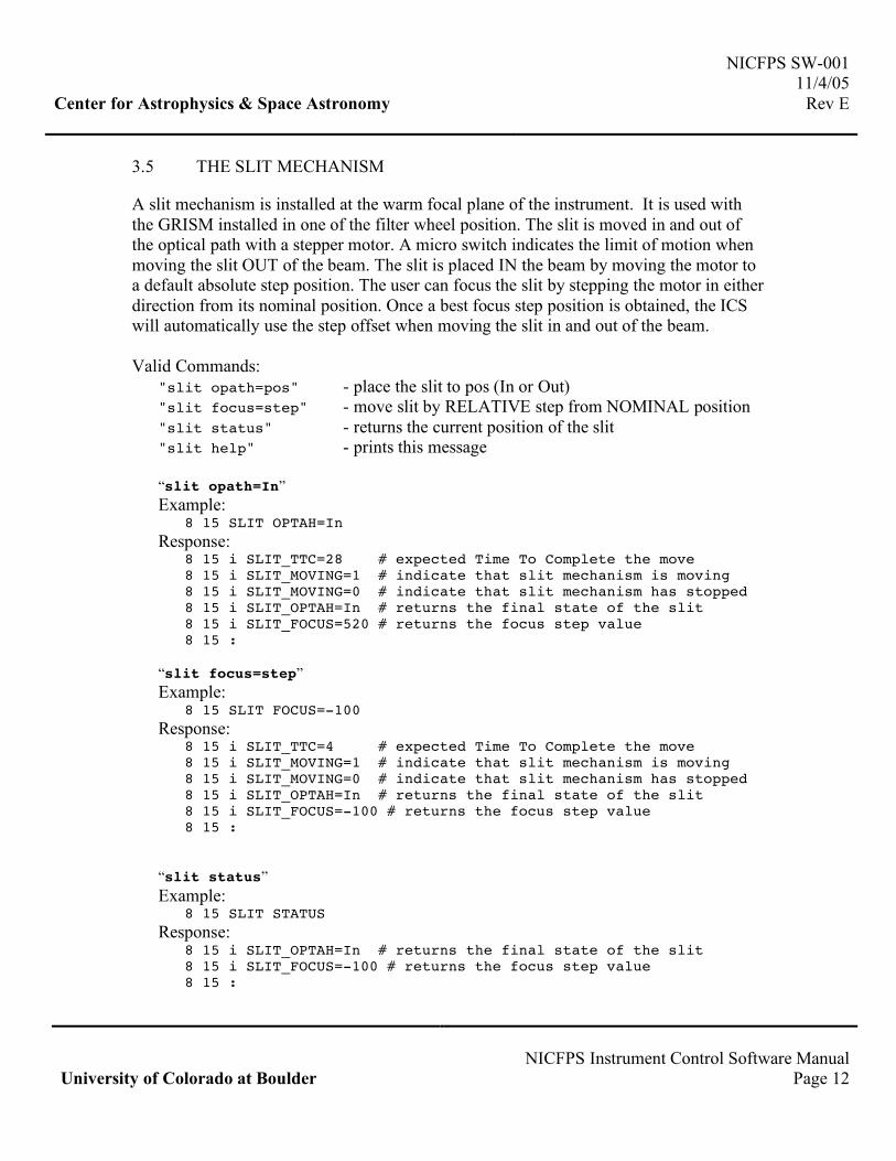
3.5 THE SLIT MECHANISM
A slit mechanism is installed at the warm focal plane of the instrument. It is used with the GRISM installed in one of the filter wheel position. The slit is moved in and out of the optical path with a stepper motor. A micro switch indicates the limit of motion when moving the slit OUT of the beam. The slit is placed IN the beam by moving the motor to a default absolute step position. The user can focus the slit by stepping the motor in either direction from its nominal position. Once a best focus step position is obtained, the ICS will automatically use the step offset when moving the slit in and out of the beam. Valid Commands:
"slit opath=pos" - place the slit to pos (In or Out) "slit focus=step" - move slit by RELATIVE step from NOMINAL position "slit status" - returns the current position of the slit "slit help" - prints this message “slit opath=In” Example: 8 15 SLIT OPTAH=In Response: 8 15 i SLIT_TTC=28 # expected Time To Complete the move
8 15 i SLIT_MOVING=1 # indicate that slit mechanism is moving 8 15 i SLIT_MOVING=0 # indicate that slit mechanism has stopped 8 15 i SLIT_OPTAH=In # returns the final state of the slit 8 15 i SLIT_FOCUS=520 # returns the focus step value 8 15 :
“slit focus=step” Example: 8 15 SLIT FOCUS=-100 Response: 8 15 i SLIT_TTC=4 # expected Time To Complete the move
8 15 i SLIT_MOVING=1 # indicate that slit mechanism is moving 8 15 i SLIT_MOVING=0 # indicate that slit mechanism has stopped 8 15 i SLIT_OPTAH=In # returns the final state of the slit 8 15 i SLIT_FOCUS=-100 # returns the focus step value 8 15 :
“slit status” Example: 8 15 SLIT STATUS Response:
8 15 i SLIT_OPTAH=In # returns the final state of the slit 8 15 i SLIT_FOCUS=-100 # returns the focus step value 8 15 :

NICFPS SW-001 11/4/05 Center for Astrophysics & Space Astronomy Rev E
NICFPS Instrument Control Software Manual University of Colorado at Boulder Page 13
3.6 COMMANDING THE FILTER WHEELS
NIC-FPS has three filter wheels with each 7 openings for a total of 18 filters (with an open/clear position on each wheel). A file is kept by the ICS containing the list of filters currently available and the corresponding position of each of the three wheels. This file (NICFPS/ICS/config/filters.txt) needs to be updated every time filters are installed or removed. The TUI can request the list of filter names to build the menu from which the user will select a specific filter. The TUI user is only able to select filters from that list. The list can also include possible combination of filters to be use together for special observations. The ICS understands “engineering commands” to move a specific wheel to a specific filter position. These engineering commands are not be available through the instrument window of TUI but are manually typed in the Log window. The ICS responds to filter move request with an initial estimate of the time needed to complete the move (possibly all three wheels). A completion message is sent to the HUB by the ICS after all wheels have reached their final position, or timed out and failed. Currently, each filter wheel has a single “HOME” position where the micro switches (2 for redundancy) are triggered. The HOME position corresponds to the “OPEN” position of the filter wheel (number 7). Any requested filter wheel move is done by moving the motor to a specific motor step position. The move is always performed towards the shortest distance to the final position. Every time the wheel crosses the HOME position in the preferred direction, the actual step value at the HOME position is reset to its default values (42 steps). This avoids accumulated step errors over time. The motor controller constantly keeps track of the current step position. If the controller is reset (by powering it off), the current step value is reset to a value of 0. This value is read from the motor controller before every move. If a value of 0 is returned, it is assumed that the controller has been reset and the wheel is automatically sent to the HOME position before the move to the final destination is commanded. Valid Commands:
“filters help” - prints a list of available commands and their syntax "filters status" - return the filter names and current position "filters names" - return names of all filters and combos in filters.txt "filters set=filtername" - set wheels to filtername (an entry in filters.txt) "filters move=n,m" - set wheel n to position m

NICFPS SW-001 11/4/05 Center for Astrophysics & Space Astronomy Rev E
NICFPS Instrument Control Software Manual University of Colorado at Boulder Page 14
"filters stop=n” - stop wheel n "filters getpos" - return positions and names of all wheels from filters.txt “filters gotocw=n,m" - set wheel n to pos m moving CW "filters gotoccw=n,m"- set wheel n to pos m moving CCW "filters nextcw=n" - move wheel n to next pos moving CW "filters nextccw=n" - move wheel n to next pos moving CCW "filters getinputs=n" - return status of micro switches of wheel n "filters setsteps=n,s" - sets the step position register for axis n to value s "filters getsteps=n" - returns the current step position register for axis n "filters absmove=n,s" - move wheel n to absolute step position s "filters relmove=n,s" - move wheel n by a number of steps from current position "filters home=all | 1 | 2 | 3" - move wheel to HOME position (OPEN) “FILTERS NAMES” - get and return the names of all filters
Response: FILTER_NAMES=”Open”,”MK-J”,”MK-H”,”MK-K”,”MK-L”,”MK-M”,”Y”,”Z”,…
“FILTERS SET=FILTERNAME” - position the wheels for that specific filter Example:
8 15 FILTERS SET=”MK-J” Response: 8 15 i FILTER_TTC=28 # expected Time To Complete the move
8 15 i FILTER_MOVING=1 # indicate that wheels are now moving 8 15 i FILTER_POS=1,4,1 # final position for each wheel 8 15 i FILTER_MOVING=0 # indicate that wheels are not moving 8 15 : FILTER_DONE=”MK-J” # returns name of the requested filter If an error happened, instead of the FILTER_DONE key, an ERROR will be issued with the list of known positions for each wheel (identifying the erroneous wheel):
9 17 i FILTER_TTC=28 # expected Time To Complete the move 9 17 i FILTER_MOVING=1 # indicate that wheels are now moving 9 17 i FILTER_POS=1,4,? # final position for each wheel 9 17 i FILTER_MOVING=0 # indicate that wheels are not moving 9 17 f FILTER_ERROR=”Unknown”
“FILTERS MOVE=FW,POS” - move a specific filter wheel to a specific position. Returns the final position of all three wheels and a valid filter name if any for that combination of wheel positions. The argument FW is an integer value corresponding to the wheel number (1, 2 or 3). The argument POS is an integer value between 1 and 7 corresponding to the filter position. Example:
11 18 FILTERS MOVE=2,6 #move wheel 2 to filter position 6 Response:
11 18 i FILTER_TTC=12

NICFPS SW-001 11/4/05 Center for Astrophysics & Space Astronomy Rev E
NICFPS Instrument Control Software Manual University of Colorado at Boulder Page 15
11 18 i FILTER_MOVING=1 11 18 i FILTER_POS=1,6,1 #final position for each wheel 11 18 i FILTER_MOVING=0 11 18 : FILTER_DONE=”MK-K” #“Unknown” if combo not in list
“FILTERS GETPOS” – returns the current position of all three wheels and a valid filter name if any for that combination of wheel positions. Example:
14 21 FILTERS GETPOS Response:
14 21 i FILTER_POS=1,6,1 14 21 : FILTER_DONE=”MK-K” #“Unknown” if combo not in list
“FILTERS STATUS” – returns the responses from the following commands: NAMES, GETPOS. Example:
14 21 FILTERS STATUS Response:
14 21 i FILTER_NAMES=”Open”,”MK-J”,”MK-H”,”MK-K”,”MK-L”,… 14 21 i FILTER_POS=1,6,1 14 21 : FILTER_DONE=”MK-K” #“Unknown” if combo not in list
“FILTERS GOTOCW=FW,POS” - move a specific filter wheel to a specific position in clockwise direction. Example:
11 18 FILTERS GOTOCW=2,6 #move wheel 2 to filter position 6 Response:
11 18 i FILTER_TTC=12 11 18 i FILTER_MOVING=1 11 18 i FILTER_POS=1,6,1 #final position for each wheel 11 18 i FILTER_MOVING=0 11 18 : FILTER_DONE=”MK-K” #“Unknown” if combo not in list
“FILTERS GOTOCCW=FW,POS” - move a specific filter wheel to a specific position in counter clockwise direction. Example:
11 18 FILTERS GOTOCCW=2,6 #move wheel 2 to filter position 6 Response:
11 18 i FILTER_TTC=12 11 18 i FILTER_MOVING=1 11 18 i FILTER_POS=1,6,1 #final position for each wheel 11 18 i FILTER_MOVING=0 11 18 : FILTER_DONE=”MK-K” #“Unknown” if combo not in list
“FILTERS NEXTCW=FW” - move a specific filter wheel to the next position in clockwise direction.

NICFPS SW-001 11/4/05 Center for Astrophysics & Space Astronomy Rev E
NICFPS Instrument Control Software Manual University of Colorado at Boulder Page 16
Example: 11 18 FILTERS NEXTCW=2 #move wheel 2 to the next CW position
Response: 11 18 i FILTER_TTC=12 11 18 i FILTER_MOVING=1 11 18 i FILTER_POS=1,6,1 #final position for each wheel 11 18 i FILTER_MOVING=0 11 18 : FILTER_DONE=”MK-K” #“Unknown” if combo not in list
“FILTERS NEXTCCW=FW” - move a specific filter wheel to the next position in counter clockwise direction. Example:
11 18 FILTERS NEXTCCW=2 #move wheel 2 to the next CW position Response:
11 18 i FILTER_TTC=12 11 18 i FILTER_MOVING=1 11 18 i FILTER_POS=1,6,1 #final position for each wheel 11 18 i FILTER_MOVING=0 11 18 : FILTER_DONE=”MK-K” #“Unknown” if combo not in list
“FILTERS ABSMOVE=FW,S” - move a specific filter wheel to the absolute step position S. Example:
11 18 FILTERS ABSMOVE=2,42 #move wheel 2 to absolute step position 42 (HOME)
Response: 11 18 i FILTER_TTC=12 11 18 i FILTER_MOVING=1 11 18 i FILTER_STEPS=2,42 11 18 i FILTER_POS=7,7,7 #final position for each wheel 11 18 i FILTER_MOVING=0 11 18 : FILTER_DONE=”OPEN” #“Unknown” if combo not in list
“FILTERS RELMOVE=FW,S” - move a specific filter wheel by a relative number of steps S (positive values for CCW, negative values for CW). Example:
11 18 FILTERS RELMOVE=2,24000 #move wheel 2 by 24000 steps in the CCW direction
Response: 11 18 i FILTER_TTC=12 11 18 i FILTER_MOVING=1 11 18 I FILTER_STEPS=2,24042 11 18 i FILTER_POS=7,6,7 #final position for each wheel 11 18 i FILTER_MOVING=0 11 18 : FILTER_DONE=”BrGr-2.17” #“Unknown” if combo not in list
“FILTERS GETSTEPS=FW” – returns the current step position for the specified wheel Example:
NICFPS SW-001 11/4/05 Center for Astrophysics & Space Astronomy Rev E
NICFPS Instrument Control Software Manual University of Colorado at Boulder Page 17
11 18 FILTERS GETSTEPS=2 Response:
11 18 : FILTER_STEPS=2,24042
“FILTERS SETSTEPS=FW,S” – sets the current step position for the specified wheel Example:
11 18 FILTERS SETSTEPS=2,0 Response:
11 18 : FILTER_STEPS=2,0
“FILTERS GETINPUTS=FW” – returns the current state of the micro switch for the specified wheel Example:
11 18 FILTERS GETINPUTS=2 Response:
11 18 : FILTER_INPUTS=2,0 #1 if at HOME, 0 otherwise
“FILTERS HOME=ALL” - move a specific filter wheel (or all of them) to HOME Example:
11 18 FILTERS HOME=ALL #move every wheel HOME Response:
11 18 i FILTER_TTC=12 11 18 i FILTER_MOVING=1 11 18 I FILTER_STEPS=2,24042 11 18 i FILTER_POS=7,6,7 #final position for each wheel 11 18 i FILTER_MOVING=0 11 18 : FILTER_DONE=”BrGr-2.17” #“Unknown” if combo not in list
3.7 COMMANDING THE FABRY-PÉROT ETALON
The etalon is mounted on a linear stage and can be moved in and out of the optical path to allow spectroscopy or imaging modes of operation. A CS-100 controls the optical characteristics of the etalon. Valid Commands:
"fp getpos" - get the current position of the FP (In | Out) "fp reset" - resets CS100 (X=Y=Z=0) and initializes motor controller "fp opath=pos" - place the FP to pos (In or Out) "fp setx=value" - set the CS100 X axis to given value "fp sety=value" - set the CS100 Y axis to given value "fp setz=value" - set the CS100 Z axis to given value "fp setzw=value" - set the CS100 Z axis to given wavelength value

NICFPS SW-001 11/4/05 Center for Astrophysics & Space Astronomy Rev E
NICFPS Instrument Control Software Manual University of Colorado at Boulder Page 18
"fp wavecal" - return the wavelength calibration coefficients "fp getxyz" - return the current X,Y and Z of the FP "fp rtime=value" - set Response Time to value (0.2,0.5,0.7,1.0,1.2,...3.7) "fp mode=value" - set the mode to value (Balance | Operate)" "fp getmode" - return the current mode "fp control=value" - set the control to value (Local | Remote) "fp out_of_range" - return 1 if FP is out_of_range, 0 otherwise "fp openCS100" - connects to the CS-100 socket "fp closeCS100" - disconnects from the CS-100 socket "fp status" - returns the current status of the FP "fp help" - prints this message
3.7.1 Linear Stage
Valid Commands: “FP GETPOS” - get and return current position of the Fabry-Pérot Response:
FP_OPATH=In # or Out
“FP OPATH=IN” (or OUT) - positions the FP IN (or OUT) the optical axis Example:
9 72 FP OPATH=OUT Response: 9 72 i FP_TTC=30 #expected time_to_complete move
9 72 i FP_MOVING=1 # indicates move has started 9 72 i FP_MOVING=0 # indicates move has stopped 9 72 : FP_OPATH=Out # returns final position If an error happened, return message with unknown position:
9 72 i FP_TTC=30 9 72 i FP_MOVING=1 9 72 i FP_MOVING=0 9 72 i FP_OPATH=? 9 72 f FP_ERROR=”Timed Out”
3.7.2 CS-100 Controller
The CS-100 controller can be manually or remotely operated to adjust the parameters of the Fabry-Pérot etalon. The etalon is adjusted by aligning and choosing a spacing of the plates corresponding to a specific wavelength. The spacing is modified by applying voltages on stacks of piezo-electric and the spacing is measured by capacitors. The spacing along the X and Y-axis adjusts the parallelism and the Z-axis changes the
NICFPS SW-001 11/4/05 Center for Astrophysics & Space Astronomy Rev E
NICFPS Instrument Control Software Manual University of Colorado at Boulder Page 19
spacing between the plates. The parallelism of the plates is maintained over time by a closed-loop feedback system between the etalon and the CS-100. A pre-defined conversion factor will be used to change the user requested wavelength (in microns) to number of steps for the Z-axis. Not all commands need to be supported by the TUI, but all are available as ICS engineering commands. The only information that the user can get back from the CS-100 are the Z position and a 2-bit status for the OUT OF RANGE and BALANCE/OPERATE mode indicators. Valid Commands:
“FP SETAXIS=POS” - adjust the axis (X,Y or Z) step position (from –2048 to +2047) Example:
5 7 FP SETX=128 #set the spacing of the plates along the X axis Response:
5 7 : FP_X=128 #returns the final position. For X and Y, the #requested position is returned. For Z, the #actual final position is returned
Example: 12 37 FP SETZ=128 #set the spacing of the plates along the Z axis
Response: 12 37 : FP_Z=128;FP_ZW=1.324 #returns position
Example:
15 71 FP SETY=2200 #wrong position requested Response:
15 71 w FP_ERROR=”Requested Y out of RANGE – No move performed”
“FP SETZW=POS” - adjust the Z axis position where pos is in microns Example:
7 15 FP SETZW=1.324 #set the wavelength in microns Response:
7 15 : FP_Z=128;FP_ZW=1.3241;FP_DESZW=1.3240 # returns final position in steps and microns and # the Desired position in microns
Example: 8 23 FP SETZW=5.8 #wrong position requested
Response: 8 23 w FP ERROR=”Requested Z out of RANGE – No move performed”
“FP WAVECAL” - returns the conversion factor between steps and wavelength Example:
9 27 FP WAVECAL #set the wavelength Response:
9 27 : FP_WAVECAL=0.874,1.754e-02 #wave=0.874+1.754e-02*steps

NICFPS SW-001 11/4/05 Center for Astrophysics & Space Astronomy Rev E
NICFPS Instrument Control Software Manual University of Colorado at Boulder Page 20
“FP GETXYZ” - returns the current X, Y in steps and Z in steps and microns Example:
9 27 FP GETXYZ Response:
9 27 : FP_X=128;FP_Y=0;FP_Z=128;FP_ZW=1.3240
“FP RTIME=VALUE” - sets the response time (0.2, 0.5, 0.7, 1.0, 1.2, 1.5, 1.7, 2.0, 2.2, 2.5, 2.7, 3.0, 3.2, 3.5 or 3.7 msec)
Example: 9 27 FP RTIME=0.5 #set the response time to 0.5 msec
Response: 9 27 : FP_RTIME=0.5 #returns the requested response time
Example: 9 27 FP RTIME=20 #request a wrong response time
Response: 9 27 w FP_ERROR=”Requested RTIME out of RANGE – No change performed”
“FP MODE=BALANCE | OPERATE” - selects the mode (BALANCE or OPERATE) Example:
9 27 FP MODE=BALANCE Response:
9 27 : FP_MODE=Balance
“FP GETMODE” - returns the current mode of the CS100 Example:
9 27 FP GETMODE Response:
9 27 : FP_MODE=Operate
“FP OUT_OF_RANGE” – returns a 1 if the CS100 is out of range. The ICS monitors the OUT_OF_RANGE status of the CS-100 after every command. If the CS-100 ever gets out of range, a warning message will be sent to the HUB. Example:
9 27 FP OUT_OF_RANGE Response:
9 27 : FP_OUT_OF_RANGE=0
“FP CONTROL=LOCAL | REMOTE” – Enable (LOCAL) or disable (REMOTE) the controls on the CS100 itself. The REMOTE mode prevents the user from changing the CS100 parameters directly from the knobs on the controller itself. Example:
9 27 FP CONTROL=Remote
NICFPS SW-001 11/4/05 Center for Astrophysics & Space Astronomy Rev E
NICFPS Instrument Control Software Manual University of Colorado at Boulder Page 21
Response: 9 27 : FP_CONTROL=Remote
“FP STATUS” – returns the responses from the following commands: GETPOS, GETXYZ, WAVECAL, GETMODE, RTIME, CONTROL, OUT_OF_RANGE Example:
9 27 FP STATUS Response:
9 27 : FP OPATH=’In’ 9 27 : FP_X=0;FP_Y=0;FP_Z=0;FP_ZW=0 9 27 : FP_WAVECAL=0.00e00,1.00e00,0.00e00,0.0e00 9 27 : FP_MODE=Operate 9 27 : FP_RTIME=1.0 9 27 : FP_CONTROL=Remote 9 27 : FP_OUT_OF_RANGE=0
3.8 THE WINDOW COMMAND
The Window command allows the user to select the region of the detector to read. The Rockwell H1RG detector is currently read out in two channels. When reading a window (smaller than the whole detector), the output is from a single channel. The selected window size, and the following exposures, will remain in effect until a new window is defined or is “reset”. Valid Commands:
"window Xlow Ylow Xhigh YHigh" - set corners in pixels (1 -> 1024) "window center X Y W H" - set center, Width and Height RADIUS in pixels "window reset" - resets the window to the full chip (and 2 channel mode) "window status" - prints the current window selected "window help" - prints this message
“window 11 11 138 138” - defines a 128 pixel square window starting at 11,11 Example:
9 27 window 11 11 138 138 Response:
9 27 : WINDOW=11,11,138,138
“window center 101 101 64 64” - defines 127 pixel square centered at 101,101 Example:
9 27 window center 101 101 64 64 Response:
9 27 : WINDOW=38,38,164,164

NICFPS SW-001 11/4/05 Center for Astrophysics & Space Astronomy Rev E
NICFPS Instrument Control Software Manual University of Colorado at Boulder Page 22
“window reset” Example:
9 27 window reset Response:
9 27 : WINDOW=1,1,1024,1024
3.9 THE FOWLER SAMPLING COMMAND
The Correlated Double Sampling (CDS) and more generally, the Fowler Sampling (FS) allows the user to reduce the read noise by reading the same image multiple times. This is possible since the H1RG detector is read non-destructively. When idle, the H1RG is in a constant fast clearing loop mode. At the start of an exposure, the loop is stopped and the chip is cleared pixel-by-pixel. In the normal single read mode, the exposure countdown is started and when completed, the chip is read. If the Fowler Sampling is selected, the chip is read a NFS times (Number of Fowler Sampling) before the exposure countdown and NFS times after the exposure is completed. Each corresponding pairs of images from the start and the end of the exposure can then be subtracted to get the signal from the same exposure time. These images can then be averaged to reduce then read noise. The CDS is a special case of the Fowler Sampling when NFS is equal to 1. The default readout mode for NICFPS is with a NFS=0. Any change to the value of NFS will affect all successive exposure until the value is changed again. The sequence for each of the readout mode is:
Single Sampling: clear + Integrate + Read CDS (NFS=1): clear + Read + Integrate + Read Fowler (NFS=n): clear + n_Read + Integrate + n_Read
Valid Commands:
"fowler nfs=v" - sets the number of “reads” before and after the exposure "fowler status" - prints the current value for NFS "fowler help" - prints this message
Example:
fowler nfs=1 - turn CDS on Response:
: NFS=1
Example: fowler nfs=4 - selects 4 reads before and 4 reads after exposure
NICFPS SW-001 11/4/05 Center for Astrophysics & Space Astronomy Rev E
NICFPS Instrument Control Software Manual University of Colorado at Boulder Page 23
Response: : NFS=4
Example: fowler nfs=0 - turn Fowler sampling off
Response: : NFS=4
3.10 THE EXPOSE COMMAND
The expose command will access the LEACH controller, start the exposure and read the chip after a number of seconds. As described above, the readout of the chip can be performed in a number of ways: full window, subarray, single sampling, correlated sampling and Fowler sampling. Valid Commands:
"expose object time=s basename=f" - starts object exposure of s seconds "expose flat time=s basename=f" - starts flat exposure of s seconds "expose dark time=s basename=f" - starts dark exposure of s seconds "expose test time=s basename=f" - starts a test pattern exposures "expose stop" - immediately finishes and reads current exposure "expose fastclear=n" - performs n fastclear of the chip "expose buffered" - set H1RG to use the BUFFERED mode "expose unbuffered" - set H1RG to use the UNBUFFERED mode (default) "expose chdir=dir" - change the root directory where images are saved
"expose init" - initializes the Leach controller "expose help" - prints this message
“expose object time=S [basename=string]” “expose flat time=S [basename=string]”
“expose dark time=S [basename=string]” “expose test time=s [basename=string]” The only variation in the expose command above is its type: object, flat, dark or test (controller test pattern), which will be reflected in the FITS header. The time is required and expected in seconds. If the basename is specified, it is used as a full Unix path name. If the HUB doesn’t provide the basename, the filenames are determined by the ICS's path, name and number.
Example:
expose dark time=30 expose object time=30 basename="/export/images/DD01/img_0023.fits”
NICFPS SW-001 11/4/05 Center for Astrophysics & Space Astronomy Rev E
NICFPS Instrument Control Software Manual University of Colorado at Boulder Page 24
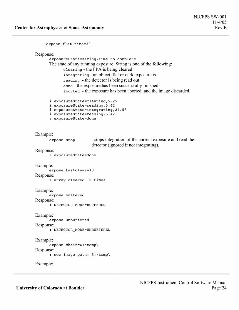
expose flat time=30 Response: exposureState=string,time_to_complete
The state of any running exposure. String is one of the following: clearing - the FPA is being cleared integrating - an object, flat or dark exposure is reading - the detector is being read out. done - the exposure has been successfully finished. aborted - the exposure has been aborted, and the image discarded.
i exposureState=clearing,5.25 i exposureState=reading,5.42 i exposureState=integrating,24.58 i exposureState=reading,5.42 : exposureState=done
Example:
expose stop - stops integration of the current exposure and read the detector (ignored if not integrating).
Response: : exposureState=done Example:
expose fastclear=10 Response: : array cleared 10 times Example:
expose buffered Response: : DETECTOR_MODE=BUFFERED Example:
expose unbuffered Response: : DETECTOR_MODE=UNBUFFERED Example:
expose chdir=Z:\temp\ Response: : new image path: Z:\temp\ Example:

NICFPS SW-001 11/4/05 Center for Astrophysics & Space Astronomy Rev E
NICFPS Instrument Control Software Manual University of Colorado at Boulder Page 25
expose init Response: : DETECTOR_MODE=UNBUFFERED
4. EXPOSURE TIME DETERMINATION
The minimum exposure time depends on the number of readout channels, the current size of the window and the number of samples read (Correlated Double Sampling and Fowler). With the current controller configuration, the readout time of the full chip (1024x1024) with two channels is about 5.4 seconds, which corresponds to the smallest exposure time. Another point to consider is the fact that the readout of the H1RG is non-destructive and thus the integration on any specific pixel starts as soon as the pixel has been cleared. The clearing is done row-by-row and it takes about 5.4 to reset the whole chip. Once an exposure has been requested, the chip is always cleared first, no matter which readout mode was selected (normal with NFS=0, CDS with NFS=1 or Fowler with NFS>1). The detector is then read a number of times specified by the value of NFS. The system then pauses to integrate a number of seconds and finally read out NFS number of times. The shortest achievable exposure time for a full frame image is equal to the time it takes to clear the chip.
Figure 2. The various read out modes and corresponding exposure times.

NICFPS SW-001 11/4/05 Center for Astrophysics & Space Astronomy Rev E
NICFPS Instrument Control Software Manual University of Colorado at Boulder Page 26
The requested integration time at the detector controller level is really the time to pause between the first series of read and the last series of read (T’ in figure 2). The exposure time requested by the user will be modified by the ICS to take into account the current observing mode and the size of the array (time to clear/read the chip) and the new integration time (T’) will be the one the ICS will use when commanding the controller. The actual exposure time for NFS=0 is the time_to_clear (Tc) plus the new integration time (T’) which should correspond to the user requested exposure time. For a CDS read out mode, the exposure time of the subtracted CDS image is the time_to_read (Tr) plus the new integration time (T’). The final read will have a corresponding exposure time of Tc+Tr+T’. For a Fowler sampling of NFS=2, the exposure time of the subtracted image is the difference between the start time of each read (NFS * Tr + T’).
5. FITS FORMAT AND KEYWORDS
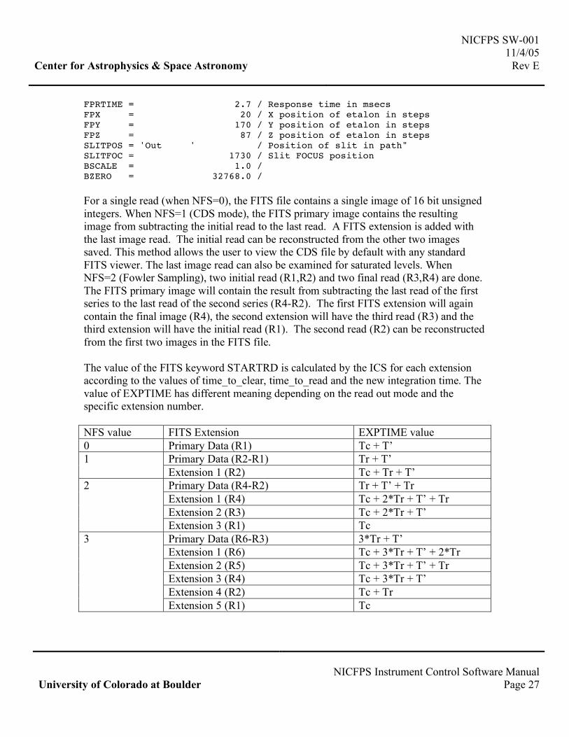
When an exposure is taken and an image is read from the detector, it is written by the ICS in a FITS format with a series of keywords representing the current state of the instrument. The HUB will then read this file and add to it another set of keywords related to the telescope (pointing, WCS, ambient weather, etc.) Below is the list of all possible FITS keywords included by the ICS. Only the keywords relevant to the current mode of operation will be included in the FITS header. EXTNAME = 'CDS ' DATE-OBS= '2005-09-21T04:05:41.126000' / TAI time at start of exposure MJD-OBS = 2453634.670243056 / Mean Julian Date of exposure STARTCLR= '2005-09-21T04:05:09.126000' / UTC time at start of exposure STARTDRD= '2005-09-21T04:05:19.986000' / UTC time at start final read ENDRD = '2005-09-21T04:05:25.236000' / UTC time at end of final frame TIME2CLR= 5.25 / Estimated time (sec) to clear the chip TIME2RD = 5.41 / Estimated time (sec) to read the chip EXPTIME = 5.411 / Actual exposure time of CDS IMAGETYP= 'OBJECT ' / Type of image taken CNPIX1 = 1 / Lower Left X pixel pos of window CNPIX2 = 1 / Lower Left Y pixel pos of window FILTER = 'Z ' / The name of the current filter FILTER1M= 4 / The physical position of filter wheel1 FILTER2M= 7 / The physical position of filter wheel2 FILTER3M= 7 / The physical position of filter wheel3 PRESSURE= 1.161E-005 / Instrument pressure in Torr TEMP1VAL= 76.462 / Temperature from LN2_Tank in K TEMP2VAL= 83.672 / Temperature from Bench-FPA in K TEMP3VAL= 97.005 / Temperature from Bench-Front in K TEMP4VAL= 144.17 / Temperature from Shield in K FPINBEAM= 'Out ' / Position of etalon
NICFPS SW-001 11/4/05 Center for Astrophysics & Space Astronomy Rev E
NICFPS Instrument Control Software Manual University of Colorado at Boulder Page 27
FPRTIME = 2.7 / Response time in msecs FPX = 20 / X position of etalon in steps FPY = 170 / Y position of etalon in steps FPZ = 87 / Z position of etalon in steps SLITPOS = 'Out ' / Position of slit in path" SLITFOC = 1730 / Slit FOCUS position BSCALE = 1.0 / BZERO = 32768.0 / For a single read (when NFS=0), the FITS file contains a single image of 16 bit unsigned integers. When NFS=1 (CDS mode), the FITS primary image contains the resulting image from subtracting the initial read to the last read. A FITS extension is added with the last image read. The initial read can be reconstructed from the other two images saved. This method allows the user to view the CDS file by default with any standard FITS viewer. The last image read can also be examined for saturated levels. When NFS=2 (Fowler Sampling), two initial read (R1,R2) and two final read (R3,R4) are done. The FITS primary image will contain the result from subtracting the last read of the first series to the last read of the second series (R4-R2). The first FITS extension will again contain the final image (R4), the second extension will have the third read (R3) and the third extension will have the initial read (R1). The second read (R2) can be reconstructed from the first two images in the FITS file. The value of the FITS keyword STARTRD is calculated by the ICS for each extension according to the values of time_to_clear, time_to_read and the new integration time. The value of EXPTIME has different meaning depending on the read out mode and the specific extension number. NFS value FITS Extension EXPTIME value 0 Primary Data (R1) Tc + T’
Primary Data (R2-R1) Tr + T’ 1 Extension 1 (R2) Tc + Tr + T’ Primary Data (R4-R2) Tr + T’ + Tr Extension 1 (R4) Tc + 2*Tr + T’ + Tr Extension 2 (R3) Tc + 2*Tr + T’
2
Extension 3 (R1) Tc Primary Data (R6-R3) 3*Tr + T’ Extension 1 (R6) Tc + 3*Tr + T’ + 2*Tr Extension 2 (R5) Tc + 3*Tr + T’ + Tr Extension 3 (R4) Tc + 3*Tr + T’ Extension 4 (R2) Tc + Tr
3
Extension 5 (R1) Tc
Related Documents