NICA X Codec System Reference Manual

Welcome message from author
This document is posted to help you gain knowledge. Please leave a comment to let me know what you think about it! Share it to your friends and learn new things together.
Transcript
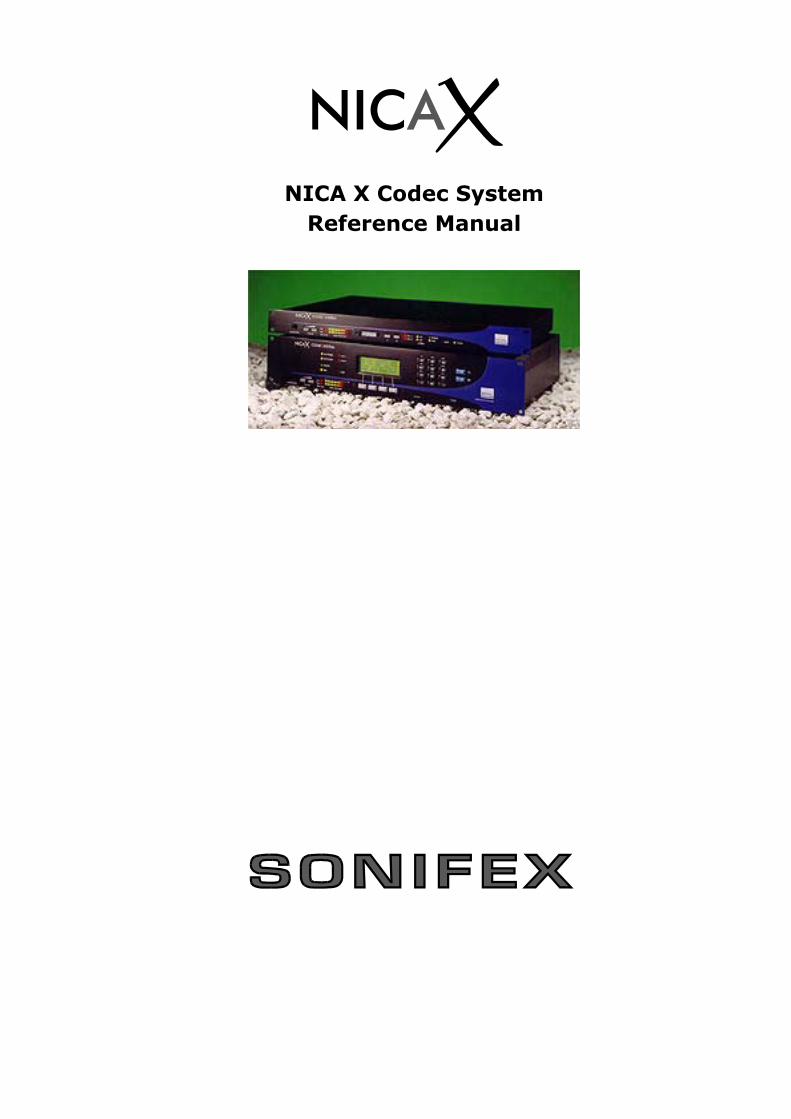
NICA X Codec SystemReference Manual

Important Note :
‘Appendix B - Regulatory Statement’ must be drawn to the users and installers attention before the use orinstallation of this product
Sonifex Ltd, 2002All Rights ReservedManual V7.00 August 2002, for software release 2.10, July 2001
Sonifex Ltd, 61, Station Road, Irthlingborough,Northants, NN9 5QE, England.Tel: +44 (0)1933 650 700Fax: +44 (0)1933 650 726Email: [email protected]: http://www.sonifex.co.uk
Information in this document is subject to change without notice and does not represent a commitment on thepart of the vendor. Sonifex Ltd shall not be liable for any loss or damage whatsoever arising from the use ofinformation or any error contained in this manual. Sonifex Ltd reserves the right to revise the information in thisManual from time to time without notice.
No part of this manual may be reproduced or transmitted in any form or by any means, electronic or mechanical,including photocopying, recording, information storage and retrieval systems, for any purpose other than thepurchaser’s personal use, without the express written permission of Sonifex Ltd. Unless otherwise noted, allnames of companies, products and persons contained herein are part of a completely fictitious adaptation and aredesigned solely to document the use of Sonifex product.

NICA X Reference Manual
CONTENTS Warranty And Safety Information ...................................................................................................... i
Warranty and Liability.......................................................................................................... iReturning the Warranty Card ................................................................................................ iiUnpacking the NICA X.......................................................................................................... iiSafety of Mains Operated Equipment ..................................................................................... iiFuse Rating ........................................................................................................................ iiPower Cable and Connection................................................................................................. ii
Chapter 1 Introduction .................................................................................................................... 11.1 - Overview.................................................................................................................... 1
1.1.1 - Coding Standards .............................................................................................. 11.1.2 - Line Interfaces .................................................................................................. 1
1.2 - Model Numbers And Specifications................................................................................. 2Chapter 2 Connection Details And Indicators ...................................................................................... 3
2.1 - Power ........................................................................................................................ 32.2 - X.21 Ports .................................................................................................................. 32.3 - ISDN S Bus................................................................................................................. 32.4 - RS232 Remote Control Port .......................................................................................... 32.5 - Auxiliary RS232 Data Port ........................................................................................... 32.6 - Audio Inputs And Outputs............................................................................................. 32.7 - External Inputs ........................................................................................................... 42.8 - External Outputs ......................................................................................................... 52.9 - Headphone Monitor And Level Indicators ........................................................................ 52.10 - Power Indicator ......................................................................................................... 52.11 - Frame Indicators - CH1, CH2....................................................................................... 52.12 - Loop Indicator........................................................................................................... 52.13 - Call Indicators ........................................................................................................... 52.14 - IMUX Indicator .......................................................................................................... 52.15 - Backup Indicator ....................................................................................................... 52.16- Level Indicators.......................................................................................................... 5
Chapter 3 Operation........................................................................................................................ 63.1 - Codec Configuration..................................................................................................... 6
3.1.1 - apt-X100 Codec Specifics ................................................................................... 63.1.1.1 - Modes For apt-X100 ................................................................................ 63.1.1.2 - Coding Delays......................................................................................... 63.1.1.3 – Auto Synchronisation .............................................................................. 73.1.1.4 - CLEAR Mode ........................................................................................... 73.1.1.5 - IMUX Mode............................................................................................. 73.1.1.6 - Stereo/Mono Operation ............................................................................ 73.1.1.7 - Auxiliary Data ......................................................................................... 73.1.1.8 - Compatibility .......................................................................................... 8
3.1.2 - MPEGL2/G.722 Codec Specifics ........................................................................... 83.1.2.1 - Modes For MPEGL2 .................................................................................. 83.1.2.2 – G.722 Coding ......................................................................................... 83.1.2.3 - MPEGL2 Coding....................................................................................... 83.1.2.4 - Coding Delays......................................................................................... 83.1.2.5 - Stereo/Mono Operation ............................................................................ 93.1.2.6 - Compatibility .......................................................................................... 93.1.2.7 - Auxiliary Data ......................................................................................... 9
3.1.3 - Loop Back ........................................................................................................ 93.1.4 - CH1 Mic Or Line Input ........................................................................................ 93.1.5 – Mono Mix Of L & R Audio Inputs.......................................................................... 93.1.6 - X21 Clock Source .............................................................................................. 10
3.2 - X21 Breakout Port (NICA X-2 only)................................................................................ 103.3 - Dip Switches – NICA X-1 .............................................................................................. 103.4 - Audio Inputs And Outputs............................................................................................. 11
3.4.1 - Audio Option Modules ........................................................................................ 113.5 - F1 & F2 Programmable Function Keys ............................................................................ 113.6 - External Inputs ........................................................................................................... 123.7 - External Outputs ......................................................................................................... 123.8 - Pin Protection.............................................................................................................. 133.9 - Remote/Inband Control ................................................................................................ 13
Chapter 4 ISDN Terminal Adapter Configuration ................................................................................. 144.1 - Data Rate................................................................................................................... 144.2 - Multiple Subscriber Numbering - MSN ............................................................................ 144.3 - B Channel Mapping ...................................................................................................... 144.4 - Sub Addressing ........................................................................................................... 144.5 - Call In Permit.............................................................................................................. 154.6 - Dialling Prefix.............................................................................................................. 154.7 - Timeout ..................................................................................................................... 154.8 - Buzzer On Call In/Drop ................................................................................................ 15
Chapter 5 Front Panel Control .......................................................................................................... 16
NICA X Reference Manual
5.1 - User Interface............................................................................................................. 165.2 - Power Up Top Menu..................................................................................................... 165.2 - Menu Tree.................................................................................................................. 16
5.3.1 - Auto Detect ...................................................................................................... 215.4 - Making An ISDN Call.................................................................................................... 21
5.4.1 - Making A Call From The Book.............................................................................. 215.4.2 - Making A Call With A Sub-Address....................................................................... 22
5.5 - Clearing A Call – Stop .................................................................................................. 225.6 - Answering A Call ........................................................................................................ 225.7 - Call Termination Causes ............................................................................................... 235.8 - Book Entries ............................................................................................................... 24
Chapter 6 Backup Operation ............................................................................................................ 256.1 – Custom Applications.................................................................................................... 256.2 - Backup Configuration................................................................................................... 256.3 - Backup Display - NICA X-2 only .................................................................................... 276.4 – Operational Examples.................................................................................................. 286.5 - Audio Switch Module (Optional)..................................................................................... 326.6 – State Machine 2.......................................................................................................... 32
6.6.1 - Operating States ............................................................................................... 326.6.2 – User Interface .................................................................................................. 336.6.3 – Configuration ................................................................................................... 33
Chapter 7 Application Diagrams........................................................................................................ 35Chapter 8 Remote Control Protocol ................................................................................................... 40
8.1 - Revision ..................................................................................................................... 408.2 - Introduction ............................................................................................................... 408.3 - Protocol ..................................................................................................................... 408.4 - Command List............................................................................................................. 41Activate Relay (REL)............................................................................................................ 41Answer Call (ANS)............................................................................................................... 41Book Dial (DBK).................................................................................................................. 41Configure Backup - Enable Backup (CBE) ............................................................................... 41Configure Backup - External Input (CBI) ................................................................................ 41Configure Backup - General Settings (CBG) ............................................................................ 41Configure Backup - ISDN numbers (CBN)............................................................................... 42Configure Backup - Monitor Settings (CBM) ............................................................................ 42Configure Backup - Primary Settings (CBP) ............................................................................ 42Configure Backup - Reserve Settings (CBR)............................................................................ 43Configure Backup - Switch Backup (CBS) ............................................................................... 43Configure Call Timeout Setting (CCT)..................................................................................... 43Configure System PINS (PST) .............................................................................................. 43Configure TA - Answer Option (CTA)...................................................................................... 44Configure TA - Call Permit Numbers (CTN) ............................................................................. 44Configure TA - Channel Settings (CTC) .................................................................................. 44Edit Book Entry (BKE).......................................................................................................... 44Enable/Disable LoopBack (LBK)............................................................................................. 44Enable/Disable System Options (OPT).................................................................................... 45Incoming Calling Line Identification (CLI) ............................................................................... 45Information (INF)................................................................................................................ 45Interface Revision (IFR) ....................................................................................................... 45Manual Dial (DIL)................................................................................................................ 45NICA X Status (STS) ........................................................................................................... 46Null Command (NUL)........................................................................................................... 46Present Pin (PIN) ................................................................................................................ 46Programme Optical Input Commands (EXI) ............................................................................ 46Read Inputs (RIP) ............................................................................................................... 47Read Relay Outputs (ROP) ................................................................................................... 47Read Silence Detector (RTH) ................................................................................................ 47Read System Switches (RSW)............................................................................................... 47Reject Call (REJ) ................................................................................................................. 47Select Relay Output Actions (EXO) ........................................................................................ 48Select Remote Control Inband Enable (REM)........................................................................... 48Set Auxiliary Data Rate (AUX)............................................................................................... 48Set Codec Mode (MOD)........................................................................................................ 48Signal Private User (SPU)..................................................................................................... 48Sound System Buzzer (BUZ) ................................................................................................ 48Stop Call (STP) ................................................................................................................... 49System Reset (RES) ............................................................................................................ 498.5 - Response Codes.......................................................................................................... 49
Appendix A Connection Details ......................................................................................................... 50A.1 X21 Ports ..................................................................................................................... 50A.2 Auxiliary RS232 Data Port .............................................................................................. 50A.3 Remote Control Port ...................................................................................................... 50A.4 External Outputs ........................................................................................................... 51

NICA X Reference Manual
A.5 External Inputs ............................................................................................................. 51A.6 Audio ........................................................................................................................... 51
Appendix B Regulatory Statement..................................................................................................... 52B.1 - CE Marking................................................................................................................. 52B.2 - EMC Testing ............................................................................................................... 52B.3 - Electrostatic Discharge................................................................................................. 52B.4 - Radiated Immunity ...................................................................................................... 52B.5 - Radiated Emissions...................................................................................................... 52B.6 - TA Module .................................................................................................................. 52B.7 - Safety & Approval Notice.............................................................................................. 52
Appendix C The apt-X100 Audio Data Compression System.................................................................. 53C.1 - Introduction ............................................................................................................... 53C.2 - Linear PCM Digital Audio Coding.................................................................................... 53C.3 - Characteristics Of Audio ............................................................................................... 53C.4 - ADPCM Audio Coding ................................................................................................... 54C.5 - Sub-Band Coding ........................................................................................................ 54C.6 - Backward Adaptive Quantisation ................................................................................... 54C.7 - Linear Prediction ......................................................................................................... 54C.8 - apt-X100 Sub-Band ADPCM ......................................................................................... 55C.9 - Inherent Properties...................................................................................................... 55
Appendix D Specifications ................................................................................................................ 56

NICA X Reference Manual
NICA X Reference Manual
i
WARRANTY AND SAFETY INFORMATION
Warranty and Liability
Important: the purchaser is advised to read this clause(a) The Company agrees to repair or (at its discretion) replace Goods which are found to be defective (fair wearand tear excepted) and which are returned to the Company within 12 months of the date of despatch providedthat each of the following are satisfied:
(i) notification of any defect is given to the Company immediately upon its becoming apparent to thePurchaser;
(ii) the Goods have only been operated under normal operating conditions and have only been subject tonormal use (and in particular the Goods must have been correctly connected and must not have been subjectto high voltage or to ionising radiation and must not have been used contrary to the Company's technicalrecommendations);(iii) the Goods are returned to the Company's premises at the Purchaser's expense;(iv) any Goods or parts of Goods replaced shall become the property of the Company;(v) no work whatsoever (other than normal and proper maintenance) has been carried out to the Goods or anypart of the Goods without the Company's prior written consent;(vi) the defect has not arisen from a design made, furnished or specified by the Purchaser;(vii) the Goods have been assembled or incorporated into other goods only in accordance with any instructionsissued by the Company;(viii) the defect has not arisen from a design modified by the Purchaser;(ix) the defect has not arisen from an item manufactured by a person other than the Company. In respect of
any item manufactured by a person other than the Company, the Purchaser shall only be entitled to the benefit ofany warranty or guarantee provided by such manufacturer to the Company.(b) In respect of computer software supplied by the Company the Company does not warrant that the use of thesoftware will be uninterrupted or error free.(c) The Company accepts liability:
(i) for death or personal injury to the extent that it results from the negligence of the Company, its employees(whilst in the course of their employment) or its agents (in the course of the agency);(ii) for any breach by the Company of any statutory undertaking as to title, quiet possession and freedom fromencumbrance.
(d) Subject to conditions (a) and (c) from the time of despatch of the Goods from the Company's premises thePurchaser shall be responsible for any defect in the Goods or loss, damage, nuisance or interference whatsoeverconsequential economic or otherwise or wastage of material resulting from or caused by or to the Goods. Inparticular the Company shall not be liable for any loss of profits or other economic losses. The Companyaccordingly excludes all liability for the same.(e) At the request and expense of the Purchaser the Company will test the Goods to ascertain performance levelsand provide a report of the results of that test. The report will be accurate at the time of the test, to the best ofthe belief and knowledge of the Company, and the Company accepts no liability in respect of its accuracy beyondthat set out in Condition (a).(f) Subject to Condition (e) no representation, condition, warranty or other term, express or implied (by statute orotherwise) is given by the Company that the Goods are of any particular quality or standard or will enable thePurchaser to attain any particular performance or result, or will be suitable for any particular purpose or use underspecific conditions or will provide any particular capacity, notwithstanding that the requirement for suchperformance, result or capacity or that such particular purpose or conditions may have been known (or ought tohave been known) to the Company, its employees or agents.(g) (i) To the extent that the Company is held legally liable to the Purchaser for any single breach of contract, tort,
representation or other act or default, the Company's liability for the same shall not exceed the Price of theGoods.(ii) The restriction of liability in Condition (g)(i) shall not apply to any liability accepted by the Seller inCondition (c).
(h) Where the Goods are sold under a consumer transaction (as defined by the Consumer Transactions(Restrictions on Statements) Order 1976) the statutory rights of the Purchaser are not affected by theseConditions of Sale.
NICA X Reference Manual
ii
Returning the Warranty CardIn order to register the date of purchase so that we can keep you informed of any design improvements ormodifications, it is important to complete the warranty registration document that is enclosed with the product andreturn it to Sonifex Ltd in the UK.
For your own records you should write down the serial number (which can be found on the rear of the NICA X) andsoftware versions.
Serial Number ……………………….
Unpacking the NICA XEach NICA X is shipped in protective packaging and should be inspected for damage before use. Where an item isfound to have transit damage, notify your supplier immediately with all the relevant details of the shipment.Packing materials should be kept for inspection and also for if the product needs to be returned.
Safety of Mains Operated EquipmentThis equipment has been designed to meet the safety regulations currently advised in the country ofpurchase and it conforms to the safety regulations specified by use of the CE Mark.
The power supply is rated to 90 - 250VAC at 47 – 63Hz. Warning : There are no user serviceably parts inside the machine. If you should ever need to look inside the unit,always disconnect the mains supply before removing the equipment covers.
Fuse RatingThe NICA X has an internal fuse for the Live mains input, which is rated at 2.5A.
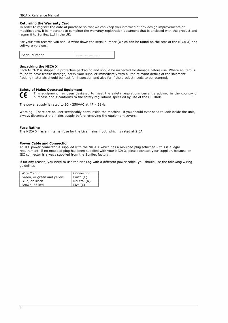
Power Cable and ConnectionAn IEC power connector is supplied with the NICA X which has a moulded plug attached – this is a legalrequirement. If no moulded plug has been supplied with your NICA X, please contact your supplier, because anIEC connector is always supplied from the Sonifex factory.
If for any reason, you need to use the Net-Log with a different power cable, you should use the following wiringguidelines
Wire Colour ConnectionGreen, or green and yellow Earth (E)Blue, or Black Neutral (N)Brown, or Red Live (L)

NICA X Reference Manual
1
CHAPTER 1 INTRODUCTION
1.1 - Overview
This Reference Manual is written for the NICA X Codec System manufactured by Sonifex Ltd. The NICA X digitalaudio codec system is described as a “codec system” for good reason. The NICA X is a highly configurableintelligent codec which can be configured by the user to suit several different modes of operation.
All the modes of operation are available in the standard unit - there are no optional extras apart from amicrophone amplifier card and an audio switch card. It is up to the user how much or how little of the functionalityof the NICA X is employed.
The principal choices are as follows:
1.1.1 - Coding Standards
The NICA X is a multi-standard codec system which supports G.722, MPEG Layer 2, and apt-X100 coding.
There are two codec card options which may be installed in the NICA X.
1. G.722 and MPEG Layer 2 card2. apt-X100 card
The 1U versions of the NICA X only accept one card of your choice. The 2U version can accept two cards; thecombinations being:
1 x apt-X100 and 1 x MPEG/G.722or
2 x MPEG/G.722
The apt-X100 card is capable of 7.5kHz mono audio at 64kbit/s and 15kHz mono audio at 128kbit/s.
The NICA X is the only codec, other than APT Ltd.’s own codecs, to employ APT’s Inverse Multiplexing Algorithm.This means that the NICA X is unique in being able to communicate over ISDN at 15kHz mono audio bandwidth,with APT Ltd.’s stereo capable codecs, such as the DSM100 and the BCF256.
The 7.5kHz “clear” mode, and the 15kHz “IMUX” mode is auto-detected in the NICA X so there is no need formanual intervention.
When two codec cards are installed in a single NICA X unit, the user can operate the system either as two discreetcodecs, or as one codec capable of auto-detecting any incoming mode, for example an auto-detect G.722, MPEGL2, apt-X100 codec.
1.1.2 - Line Interfaces
The NICA X can be operated on X21 and/or ISDN S Bus line interfaces.
On the X21 connection, the NICA X can be connected to a fixed point-to-point digital service, such as kilostream,in order to achieve a high bandwidth stereo audio connection using either MPEG Layer 2 or apt-X100 coding.
The NICA X’s maximum data rate over the X21 interface is 256kbit/s.
Over the ISDN S Bus connection, the NICA X provides the following bandwidth:
Using G.722 64kbit/s 7.5kHz mono audio bandwidthUsing MPEG 64kbit/s 8kHz mono audio bandwidth at 48kHz sampling
10kHz mono audio bandwidth at 24kHz samplingUsing apt-X100 64kbit/s 7.5kHz mono audio bandwidth
128kbit/s 15kHz mono audio bandwidth128kbit/s 7.5kHz stereo audio bandwidth
The NICA X can be used as a dedicated fixed line or ISDN codec. Alternatively, in applications where both types ofservices are employed - Studio-to-Transmitter Links for example, the NICA X can support both fixed and ISDN lines.
This means the NICA X can be used to provide stereo audio main feed to the transmitter plus an on-line ISDNbackup service which automatically switches in if the main line fails. Both fixed service and ISDN service can beconnected to the same NICA X, or if redundancy in hardware is required, then the fixed and ISDN services caneach be connected to a dedicated NICA X codec with active monitoring taking place between the two codecs.
We hope that these extensive features within the NICA X will help you now, and in the future, to create innovativeand cost effective digital audio communication solutions.

NICA X Reference Manual
2
1.2 - Model Numbers And Specifications
Model Number ISDN TA APTX100Codec
MPEG/G722 - 1
Codec
MPEG/G722 - 2
Codec
1U or 2Uunit
Keypad& LCD
NICA X-1A NO YES NO NO 1U NONICA X-1M NO NO YES NO 1U NONICA X-1AT YES YES NO NO 1U NONICA X-1MT YES NO YES NO 1U NONICA X-2A YES YES NO NO 2U YESNICA X-2M YES NO YES NO 2U YESNICA X-2AM YES YES YES NO 2U YESNICA X-2MM YES NO YES YES 2U YESNICA X-2AX NO YES NO NO 2U YESNICA X-2MX NO NO YES NO 2U YESNICA X-2AMX NO YES YES NO 2U YESNICA X-2MMX NO NO YES YES 2U YES
NICA X Reference Manual
3
CHAPTER 2 CONNECTION DETAILS AND INDICATORS
Please refer to Appendix A for detailed pin connection information. You should also read Appendix B, a RegulatoryStatement, on the electrical safety of the codec.
2.1 - Power
WARNING: This equipment must be earthed.
This unit is mains powered via an IEC filtered inlet for 90 – 250V supply. There is an internal fuse for the Livemains input. An IEC power cable is provided.
The power switch is double poled, switching the Live and Neutral.
The enclosure is earthed via an internal earth stud.
2.2 - X.21 Ports
The NICA X has two X.21 ports for connection to an ISDN Terminal Adapter or Leased Line modem etc. The portsare 15 way D-type female connectors.
The NICA X normally derives its clock from the X.21 interface. The X.21 clock can be 56kbit/s to 256kbit/sdepending on the Mode of operation (see section 3.1). Also the NICA X can generate its own internal clock for useon X.21 circuits where the clock is not provided (see section 3.1.5 ).
The X.21 ports are leased circuit interfaces restricting their use to clock and data only.
Note for NICA X-2 only :
The NICA X-2 has an X.21 DCE port (Breakout) available for use as Port 2 of the integral Terminal Adapter. Thiscan be used for the connection of an external codec. The port is a 15 way D-type female connector.
To use this port the Mode setting of Channel 2 must be set for Breakout use. (see section 3.2). This port can beset to operate at 56kbit/s or 64kbit/s.
2.3 - ISDN S Bus
The ISDN S Bus RJ45 connector should be connected to the ISDN2 termination box using the cable provided.
Note: The ISDN TA is optional in both NICA X-1 and NICA X-2 units
2.4 - RS232 Remote Control Port
The RS232 Remote Control Port connector is a 9 way D-type female connector. The supported signals are RXD,TXD, and GND.
There are also optional RS485 connections for connecting multiple NICA X units on a common bus.
2.5 - Auxiliary RS232 Data Port
The Auxiliary RS232 data port is a 9 way D-type male connector. Signals supported are RX, TX , RTS and CTS.Two ports are provided on the one connector for units with two codecs fitted.
The auxiliary data port must be enabled at both ends of a link. The baud rate is variable between 1200 and 9600for APTX100 codecs and fixed at 1200 baud for MPEG codecs. To enable the port and to set the baud rate, seesections 3.1.1.7 and 3.1.2.7. In Debug mode this port provides access to the ISDN TA management port at 9600baud.
2.6 - Audio Inputs And Outputs
There are two analogue audio inputs and two analogue audio outputs which use 3 pin XLR connectors. They areelectronically balanced line level inputs with a high impedance input and low impedance output. There is anoptional Microphone Input Module allowing CH1 INPUT to take a microphone.
The maximum headroom is 12dBu for APTX100 codecs and 18dBu for MPEG/G722 codecs and it has 0dBu gainthrough the encode and decode path. The audio bandwidth depends on the coding mode selected - See section3.1.1.1 and 3.1.2.1 for further information.

NICA X Reference Manual
4
2.7 - External Inputs
The External Input connector is a 15 way D-Type female connector. There are 8 external optically isolated inputs.They are high sensitivity opto coupled LED's with common anodes and a series 1K5 resistor.
The input can be driven by 5V logic, by switches using an external excitation supply (4.75 - 12.6V) or using thesupply voltage (12V nominal) provided on the External Input connector.
ion = 1.5mA min. imax = 10mA.
Isolation Voltage = 48V maxExcitation Voltage = 4.75-15V max
The External Inputs can be programmed to perform any command in the system. Some common uses are to :-
Trigger dialling Book entries,Change Codec Mode,Trigger Backup functions,
COMMON
IN1
R
+4.75 -12.6V
Isolated Switch Inputs Using External Power Supply
COMMON
IN1
R
Switch Inputs Using Internal Power Supply
+12VX
GND
External Logic
COMMON
IN1
R
GND
VCC

NICA X Reference Manual
5
2.8 - External Outputs
The External Output connector is a 15 way D-Type female connector. There are 8 external isolated relay outputswhich are Normally Open (NO) contacts with one shared common connection. The relay contacts are rated at1A@24Vdc and 0.5A@120Vac.
The External Relay Outputs can be programmed to switch depending on a number of circumstances for example:-
Framing indicationBackup mode runningISDN Call Up
2.9 - Headphone Monitor And Level Indicators
The headphone monitor connector is a ¼ inch stereo jack socket for A type jack plugs. The level is adjusted usingthe volume control buttons on the front panel.
The Monitor section also has a level indicator for CH1 and CH2 with a range from -15dBu to +12dBu in 3dB stepsThe audio monitored can be selected as one of the modes A, B, C or D, by pressing the two volume keystogether:-
Mode Channel 1 Channel 2A Input InputB Output OutputC Input OutputD (only if Mic module fitted) Microphone Input Output
The CH1/CH2 LED’s indicate the selection.
2.10 - Power Indicator
The power indicator is a green LED which indicates that the internal DC voltage is good.
2.11 - Frame Indicators - CH1, CH2
There are green LED decoder framing indicators for channels 1 and 2. These indicate that the DATA channels havesynchronised/framed to the incoming clock and data. These will only illuminate if the correct format data is presenti.e. the correct type of codec is at the remote end for the mode set at the NICA X.
If in Autodetect Mode, these indicators will flash whilst the unit is hunting for the correct Mode. This only occurswhen an ISDN call is active or an X.21 interface is active. See sections 3.1.1.1 and 3.1.2.1 for mode settings.
2.12 - Loop Indicator
The loop indicator is a red LED. This indicates that the unit is set to loopback. See section 3.1.3.
2.13 - Call Indicators
The Call 1 and Call 2 indicators are red LED's. They indicate that an ISDN call is present on Channel 1 and Channel2 of the Terminal Adapter respectively. On power up these LED’s will flash during the ISDN Terminal Adapter reset.
2.14 - IMUX Indicator
The IMUX indicator is a yellow LED. This indicates that the unit is set to an IMUX coding mode. See section 3.1.1.
2.15 - Backup Indicator
The BACKUP indicator is a yellow LED with the following functions :ON - This indicates that the unit is currently in the backup state. FLASHING - This indicates that the Primary has failed and the unit is running in Reserve or trying to establishReserve.See Chapter 6 for more information on the Backup Function.
2.16- Level Indicators
The level indicators represent the audio level as presented to the CH1 and CH2 audio outputs. The are purely forindication of audio present and should not be used for calibration of levels.

NICA X Reference Manual
6
CHAPTER 3 OPERATION
There are a number of ways the NICA X may be operated. The table below gives 3 scenarios and the relevantsections in the manual.
Manual sectionsNICA X-2 operated from front panel keypad and LCD display 5NICA X-1 configured from front panel dipswitches 3.3NICA X-1/2 operated via the remote control port 8
There are a number of applications which the NICA X can be used for. The table below gives 5 scenarios and therelevant sections in the manual
Manual sectionsNICA X-2 Operation on ISDN 5, 7.1NICA X-1 Operation on ISDN controlled via remote port 8, 7.1Operation on a fixed data link 7.2Operation on a fixed data link with ISDN backup 7.3,6Operation as a backup Codec to an external service 7.4,6
3.1 - Codec Configuration
Before the NICA X can be used the Codec first has to be set to the correct mode. The NICA X can be set into thecorrect Mode using :-
• DIP Switches on the NICA X-1 - see section 3.3• Keypad and Display on the NICA X-2 - see section 5• Remote Control Port on the NICA X-1 and NICA X-2 - see section 8
The sections below give information on the two types of codecs.
3.1.1 - apt-X100 Codec Specifics
The following information is relevant to NICA X units fitted with an apt-X100 codec card.
3.1.1.1 - Modes For apt-X100
Quick Reference TableMEANS OFCONTROL MENU
REMOTECONTROL DIP SWITCHES
ACTION - CONFIG- MODE
MOD 9,10,11,12
The tables below list the Codec Modes for apt-X100 versions
apt-X100Mode Name
Max. AudioBandwidth
AudioMode
DataRate kbit/s
DataMode
DataInterface
0 None Set - - - - -1 Auto Detect - - - - ISDN/X212 APT ISDN Clr-M 7.5KHz Mono 64 Clear ISDN3 APT ISDN IMUX-M 15KHz Mono 2 x 64 * IMUX ISDN4 APT ISDN IMUX-S 7.5KHz Stereo 2 x 64 * IMUX ISDN5 APT X21 64k-M 7.5KHz Mono 64 Clear X216 APT X21 128k-M 15KHz Mono 128 Clear X217 APT X21 128k-S 7.5KHz Stereo 128 Clear X218 APT X21 256K-S 15KHz Stereo 256 Clear X219 APT X21 IMUX-M 15KHz Mono 2 x 64 * IMUX X2110 APT X21 IMUX-S 7.5KHz Stereo 2 x 64 * IMUX X21
* These modes will operate on 1x 64k channel as well as 2 x 64k channels
3.1.1.2 - Coding Delays
The coding delay of the apt-X100 algorithm is considerably lower than other coding techniques such as MPEG. Theinformation below gives the delay of an encode/decode path of a NICA X. i.e. the delay between your input audiolocally and the output audio remotely. These figures do not take account of the transmission delays of the digitalservice or ISDN service. However assuming there are no satellite hops involved this should be insignificant.

NICA X Reference Manual
7
Coding Mode Coding DelayAPT 64k mono ~ 13mSAPT 256k stereo ~ 5mSAPT IMUX 2 x 64k mono ~ 13mSAPT 64k mono over ISDN (local call) ~ 17mS
3.1.1.3 – Auto Synchronisation
When operating in a CLEAR Date Mode, the NICA X sets the auto synchronisation mode of the apt-X100 chip toautomatically synchronise to the incoming data stream. In an IMUX mode the Autosync is not required as theIMUX process itself deals with the synchronisation of the audio data stream.
3.1.1.4 - CLEAR Mode
CLEAR mode will only operate at 64kbit/s on 1 channel of ISDN to give 7.5kHz mono audio. On a fixed dataservice such as a Kilostream, Satellite link or Microwave link, the NICA X can operate at either 64k, 128k or 256k.The clock can be provided by the network or internally by the NICA X.
The CLEAR mode enables the unit to operate with other products using aptX-100 coding on just 64kbit/s.
3.1.1.5 - IMUX Mode
The IMUX mode employs APT's inverse multiplexing technique known as MUCAS. This links two 64kbit/s channelstogether, taking into account any delays between the two data stream clocks and any slippage, to give a 128kbit/sdata stream which the codec can then utilise.
In IMUX mode the NICA X will operate at 7.5kHz mono over 64kbit/s, 15kHz mono over 2x64kbit/s and 7.5kHzstereo over 2x64kbit/s.
3.1.1.6 - Stereo/Mono Operation
In CLEAR mode the NICA X can operate in mono over 64kbit/s, mono or stereo at 128kbit/s, and stereo only at256kbit/s.
With IMUX modes the stereo operation is only relevant for 2 x 64kbit/s data channels. To operate in stereo modein IMUX, only one unit needs to be set to stereo as the other unit will automatically change to stereo.
In IMUX mode the NICA X can operate in mono mode at 7.5kHz audio bandwidth over 64kbit/s and 15kHz audiobandwidth over 2x64kbit/s. In IMUX mode the NICA X can operate in stereo mode at 7.5kHz audio bandwidth over2x64kbit/s.
If the unit is operating in stereo mode and one 64kbit/s data channel is lost, then the unit will continue to operateat 7.5kHz mono.
The table below summarises the variations.
Data 64kbit/sIMUX mode
2 x 64kbit/sIMUX mode
Monomode
7.5kHz 15kHz
Stereomode
7.5kHz Mono
7.5kHzStereo
3.1.1.7 - Auxiliary Data
Quick Reference TableMEANS OFCONTROL MENU
REMOTECONTROL DIP SWITCHES
ACTION - SYSTEM-CONFIG- 6.AUXDATA
AUX 6,7,8
If enabled the auxiliary data uses part of the audio data stream. Therefore the audio quality is slightly affected bythe reduction in data bits used to represent the audio. The higher the baud rate, the more data is "stolen" fromthe audio data. The apt-X100 Codec can operate at 1200, 2400, 4800, 9600 baud rate.
The auxiliary data channel within the audio data stream is only active when enabled. It will only operate withanother codec which has the auxiliary data enabled. The baud rate between two units is determined by the unitwith the highest setting. The auxiliary data can be used in any mode e.g. Mono/Stereo, CLEAR/IMUX
NOTE: If a codec has the auxiliary data enabled and connects to a codec with it disabled the audio will becorrupted.
NICA X Reference Manual
8
3.1.1.8 - Compatibility
Clear Mode
In CLEAR mode the NICA X will operate with the Nicral NICA64, NICA128, KW, SystemBase, and Glensound apt-X100 codecs, APT's DSM100, APT's DTR128 Reporter, Nicral RePORT and RePORT2 (apt-X100 based).
IMUX Mode
In IMUX mode the NICA X will operate with the Nicral NICA128, APT's DTR128 Reporter, APT's DSM100 with IMUXcard, and APT’s BCF256.
3.1.2 - MPEGL2/G.722 Codec Specifics
The following information is relevant to NICA X units fitted with an MPEG codec.
3.1.2.1 - Modes For MPEGL2
Quick Reference TableMEANS OFCONTROL MENU
REMOTECONTROL DIP SWITCHES
ACTION - CONFIG- MODE
MOD 9,10,11,12
The tables below list the Codec Modes for MPEGL2 versions
MPEG/G.722Mode Name
Max. AudioBandwidth
AudioMode
DataRate kbit/s
Algorithm DataInterface
0 None Set - - - - -1 Auto Detect - - - - ISDN/X2115 G722 ISDN-M 7.5 kHz Mono 64 G.722 ISDN16 L2 24KS ISDN-M 10 kHz Mono 64 MPEGL2 ISDN17 L2 48KS ISDN-M 8.25 kHz Mono 64 MPEGL2 ISDN18 L2 24KS X21-M 10 kHz Mono 64 - 128* MPEGL2 X2119 L2 48KS X21-M 8.25 - 15 kHz Mono 64 - 128* MPEGL2 X2120 L2 48KS X21-DM 8.25 - 15 kHz DM 64 - 128* MPEGL2 X2121 L2 48KS X21-JS 8.25 - 15 kHz Stereo 64 - 128* MPEGL2 X21
* These modes will operate on one X21 channel at either 64k or 128k
3.1.2.2 – G.722 Coding
This is ITU-T G.722 and uses statistical framing to encode/decode. There is only one mode associated with G.722which gives 7.5kHz mono audio over 64kbit/s. The sample rate is 16kHz.
Note: It is a feature of statistical framing that a G.722 decoder will not frame to silence. Therefore, audio must beinput to the encode end for a decoder to frame. Also G.722 coding does not encode 1kHz tones very well.
3.1.2.3 - MPEGL2 Coding
ISO/MPEG-1 Layer II (ISO/IEC 11172-3)ISO/MPEG-2 Layer II (ISO/IEC 13818-3)
The MPEGL2 coding modes are detailed in the table above. The MPEGL2 codec does not have any IMUX modes andtherefore can operate over 64kbit/s channels for ISDN applications, or up to 128kbit/s for fixed data linkapplications. At 64kbit/s the MPEGL2 modes can give up to 10kHz audio bandwidth. On a 128kbit/s fixed data linkthe NICA X can give 15kHz audio bandwidth in mono, stereo or dual mono.
On a fixed data service such as a Kilostream, Satellite link or Microwave link, the NICA X can operate at either 64kor 128k. The clock can be provided by the network or internally by the NICA X at 128k
3.1.2.4 - Coding Delays
The information below gives the delay of an encode/decode path of a NICA X. i.e. the delay between your inputaudio locally and the output audio remotely. These figures do not take account of the transmission delays of thedigital service or ISDN service. However assuming there are no satellite hops involved this should be insignificant.
Coding Mode Coding DelayMPEGL2 48khz sample rate mono 64k ~ 74mSMPEGL2 24kHz sample rate mono 64k ~ 136mS
NICA X Reference Manual
9
3.1.2.5 - Stereo/Mono Operation
The MPEGL2 modes can only give stereo operation over a fixed data link. The Dual Mono mode gives twoindependent audio channels with 10kHz bandwidth at 128kbit/s. The Joint Stereo mode gives 15kHz stereo audiobandwidth at 128kBit/s.
3.1.2.6 - Compatibility
The MPEG codec in the NICA X is compatible with all G.722 (statistical framing) codecs and all MPEG-1 codecs at48K sample rate and all MPEG-2 codecs at 24K sample rate. These are only relevant for 64kbit/s operation.
3.1.2.7 - Auxiliary Data
Quick Reference TableMEANS OFCONTROL MENU
REMOTECONTROL DIP SWITCHES
ACTION - SYSTEM-CONFIG- 6.AUXDATA
AUX 6,7,8
The auxiliary data uses part of the audio data stream. Therefore the audio quality is slightly affected by thereduction in data bits used to represent the audio. The MPEG Codec operates at only 1200 baud rate.
The auxiliary data channel within the data stream is always available, and is activated when data is sent.Therefore, the data capacity of a link is used for audio data unless auxiliary data is present.
3.1.3 - Loop Back
Quick Reference TableMEANS OFCONTROL MENU
REMOTECONTROL DIP SWITCHES
ACTION - SYSTEM-CONFIG- 4.LOOP
LBK 5
Loopback will encode the input audio and decode it to the output. It will operate in the mode as set, i.e. apt-x100or MPEGL2. If in an MPEG mode, a clock must be available, i.e. an ISDN call must be active, or an X.21 active orthe internal clock enabled.
When in loopback the unit cannot link to a remote codec.
3.1.4 - CH1 Mic Or Line Input
Quick Reference TableMEANS OFCONTROL MENU
REMOTECONTROL DIP SWITCHES
ACTION - SYSTEM-CONFIG- 5.OPTIONS- 1.AUDIO
OPT 4
A microphone can be connected directly to a NICA X by fitting an optional internal module. If the module is notpresent, the menu will not appear for MIC/LINE selection.
The MIC/LINE setting for audio input CH1 is set to take a Line level or Microphone level input. This can be set fromthe DIP switches (NICA X-1), front panel keypad (NICA X-2), or from the remote control port.
The Microphone input level can be adjusted at the monitor section. Depress both volume keys together until CH1 isflashing. This indicates the Microphone Input level is displayed on the CH1 level indicator. The Volume keys nowcan be used to adjust the Gain of the Microphone input.
To exit this mode, simultaneously press the two volume keys again and this will return the CH1 and CH2 LED’s toline level indication.
3.1.5 – Mono Mix Of L & R Audio Inputs
Quick Reference TableMEANS OFCONTROL MENU
REMOTECONTROL DIP SWITCHES
ACTION - SYSTEM-CONFIG- 5.OPTIONS- 1.AUDIO
OPT
The Mono Sum of L & R input is an optional feature with the Audio Switch Module Issue 2. This module is fittedinternally. If the module is not present the menu will not appear for Mono Sum of L & R selection.

NICA X Reference Manual
10
If Mono Sum of L & R is set to ON then audio input to both CH1 and CH2 audio input connectors will be summedtogether, but ONLY if the codec is set so that channel 1 is in a Mono mode. This is very useful when providingmono ISDN backup to a stereo Primary service.
3.1.6 - X21 Clock Source
Quick Reference TableMEANS OFCONTROL MENU
REMOTECONTROL DIP SWITCHES
ACTION - SYSTEM-CONFIG- 5.OPTIONS- 2.X21 CLOCK
OPT
In X21 modes the NICA X can either use an external clock provided on the X21 interface or it can generate its owninternal clock. This may be useful on leased digital circuits where a clock is not provided.
3.2 - X21 Breakout Port (NICA X-2 only)
Quick Reference TableMEANS OFCONTROL MENU
REMOTECONTROL DIP SWITCHES
ACTION - CONFIG- MODEset 24.BREAKOUT
MOD
The NICA X-2 has an X21 DCE port for use on port 2 of the internal Terminal Adapter for connection of an externalcodec. To use this port the CH2 mode must be set to Mode “24.Breakout”. (see section 3.1.1.1 and 3.1.2.1). AllISDN calls on channel 2 will now route the data to the X21 breakout port.
When in CH2 mode is set to “Breakout”, the NICA X internal codec can only operate on channel 1 of the ISDN.
3.3 - Dip Switches – NICA X-1
Quick Reference TableMEANS OFCONTROL MENU
REMOTECONTROL DIP SWITCHES
ACTION None RSW
There is a row of 12 DIP switches on the front of the NICA X-1 allowing a number of parameters to be set. A coverplate is provided to cover the DIP switches to avoid tampering.
Note that the mode settings for the codec depend on the type of codec fitted - either APTX100 or MPEG.The following table details the function of each switch.
Table 1 – NICA X-1 Dipswitch FunctionsSwitch Function Setting (ON = Down, OFF = Up)1 SWITCH PRIORITY ON = switches overwrite internal configuration2 BACKUP ON = enable backup mode3 INBAND CONTROL ON = enable inband control4 MIC I/P ENABLE ON = set CH1 input to Microphone levels5 LOOPBACK ENABLE ON = set codec into loopback6 AUX PORT ENABLE ON = enable auxiliary data channel7 AUX BAUDRATE - 2 Index to table 2 below for baud rate settings8 AUX BAUDRATE - 1 Index to table 2 below for baud rate settings9 MODE Index to table 3/4 below for Mode setting10 MODE Index to table 3/4 below for Mode setting11 MODE Index to table 3/4 below for Mode setting12 MODE Index to table 3/4 below for Mode setting
Table 2 – Auxiliary Baud Rate SettingsSW 7 SW 8 Aux Baud RateOFF OFF 1200OFF ON 2400ON OFF 4800ON ON 9600

NICA X Reference Manual
11
Table 3 – apt-x100 Codec Mode Dipswitch SettingsSW9 SW10 SW11 SW12 ModeOFF OFF OFF OFF 1 - AUTO DETECTOFF OFF OFF ON 2 - APT ISDN Clear-MonoOFF OFF ON OFF 3 - APT ISDN IMUX-MonoOFF OFF ON ON 4 - APT ISDN IMUX-StereoOFF ON OFF OFF 5 - APT X21 64k-MonoOFF ON OFF ON 6 - APT X21 128k-MonoOFF ON ON OFF 7 - APT X21 128k-StereoOFF ON ON ON 8 - APT X21 256K-StereoON OFF OFF OFF 9 - APT X21 IMUX-MonoON OFF OFF ON 10 - APT X21 IMUX-Stereo
Table 4 - MPEGL2 Codec Mode Dipswitch SettingsSW9 SW10 SW11 SW12 ModeOFF OFF OFF OFF 1 - AUTO DETECTOFF OFF OFF ON 15 - G722 ISDN-MOFF OFF ON OFF 16 - L2 24KS ISDN-MOFF OFF ON ON 17 - L2 48KS ISDN-MOFF ON OFF OFF 18 - L2 24KS X21-MOFF ON OFF ON 19 - L2 48KS X21-MOFF ON ON OFF 20 - L2 48KS X21-DMOFF ON ON ON 21 - L2 48KS X21-JS
3.4 - Audio Inputs And Outputs
The Audio Inputs and Outputs will have different uses depending on the type of NICA X and the currentconfiguration. The table below details :-
NICA X typemode setting
Audio InputXLR CH1
Audio InputXLR CH2
Audio OutputXLR CH1
Audio OutputXLR CH2
NICA X-1A/1AT/2A APT-CH1 * APT-CH2 APT-CH1 ** APT-CH2 **NICA X-1M/1MT/2M MPEG-CH1 * MPEG-CH2 MPEG-CH1** MPEG-CH2**NICA X-2AMCh 1 APT modeCh 2 no mode/APT mode
APT-CH1 APT-CH2 APT-CH1 APT-CH2
NICA X-2AMCh 1 MPEG modeCh 2 APT mode
MPEG-CH1 APT-CH1 MPEG-CH1 APT-CH2
NICA X-2MMCh 1 MPEG1 modeCh 2 no mode
MPEG1-CH1 MPEG1-CH2 MPEG1-CH1 MPEG1-CH2
NICA X-2MMCh 1 MPEG1 modeCh 2 MPEG2 mode
MPEG1-CH1 MPEG2-CH1 MPEG1-CH1 MPEG2-CH1
* mono inputs must be applied to channel 1 audio input XLR** mono outputs are available on channel 1 and channel 2 audio output XLR
3.4.1 - Audio Option Modules
The NICA X has an internal position for an Audio Option Module. The available options are :-
Module Feature See manual sectionNIX05 Issue 1 Audio Switcher for Backup operation 6.3 NIX05 Issue 2 Audio Switcher for Backup operation with CH1
and CH2 mono sum.6.3 and 3.1.5
NIX03 Issue 3 Microphone Amp 3.1.4
3.5 - F1 & F2 Programmable Function Keys
Quick Reference TableMEANS OFCONTROL MENU
REMOTECONTROL DIP
SWITCHESACTION - SYSTEM-CONFIG
- 8.I/O- 1.INPUT TYPE& 2.INPUT COMMAND
EXI

NICA X Reference Manual
12
The two function keys can be programmed to perform any command in the system. Effectively they areprogrammed with a remote control command. This means they can also perform inband control of the remotecodec as well as the local codec. The Function keys will override the DIP Switch settings currently set on a NICA X-1 unit.
The function keys are programmed either from the front panel keypad and display (see section 5) (NICA X-2) orfrom the remote control port (see section 8). The function keys can be set to perform a latching or momentarytype action and can also perform an A and B command relating to the key press.
Here are some examples :-
1. If set to latching action, pressing the key will perform command A and releasing the key will perform commandB, e.g. Loopback ON when key depressed, Loopback OFF when key released.
2. If set to momentary action, pressing and releasing will perform command A and pressing and releasing againwill perform command B, e.g. pressing the key will toggle between one mode and another mode.
3. If F1 and F2 are set to latching action, with just command A used on both F1 and F2, pressing and releasing F1could dial a Book entry, and pressing and releasing F2 could clear down all ISDN calls.
3.6 - External Inputs
Quick Reference TableMEANS OFCONTROL MENU
REMOTECONTROL
DIPSWITCHES
ACTION - SYSTEM-CONFIG- 8.I/O- 1.INPUT TYPE & 2.INPUT COMMAND
EXIRIP (readsinput state)
The external inputs are 8 optically isolated inputs (see Appendix A.5 for connection details). The external inputscan be programmed to perform any command in the system. Effectively they are programmed with a remotecontrol command. This means they can also perform inband control of the remote codec as well as the local codec.The external input command will override the DIP Switch settings currently set on a NICA X-1 unit.
The external inputs are programmed either from the front panel keypad and display (see section 5) (NICA X-2) orfrom the remote control port (see section 8). In a new system they are factory set to perform dial of BOOK entry101 on input 1 through to dial BOOK entry 108 on input 8. These, of course, can be changed to any command.
The external inputs can be set to perform a latching or momentary type action and can also perform an A and Bcommand relating to the active or inactive state. Here are some examples:-
1. If set to latching action, taking an input high will perform command A and taking it low will perform commandB, e.g. Loopback ON when active, Loopback OFF when inactive.
2. If set to momentary action, pulsing an input high to low will perform command A and pulsing again willperform command B, e.g. pulses will toggle between one mode and another mode.
3.7 - External Outputs
Quick Reference TableMEANS OFCONTROL MENU
REMOTECONTROL DIP SWITCHES
ACTION - SYSTEM-CONFIG- 8.I/O- 3.RELAY MODE
EXO, REL, ROP
The external outputs are 8 relays with Normally Open contacts with one shared common connection (see AppendixA.4 for connection details). Each external output has a default setting as listed in the table below or it has a USERsetting. The USER setting allows the Relay to be switched by a programmed event in the system. For example anopto input on a remote NICA X could be programmed to switch a relay on the local NICA X.
ExternalOutput
DefaultFunction
Description
1 CH1 Frame ON when CH1 Frames2 CH2 Frame ON when CH2 Frames3 CH 1 Call ON when CH1 has ISDN Call4 CH 2 Call ON when CH2 has ISDN Call5 Unit Active ON when unit alive and running6 Backup State ON when unit is in performing BACKUP7 Backup Fail ON when unit failed to make BACKUP link8 Stereo ON when main running mode is Stereo.

NICA X Reference Manual
13
3.8 - Pin Protection
Quick Reference TableMEANS OFCONTROL MENU
REMOTECONTROL DIP
SWITCHESACTION - SYSTEM-CONFIG
- 9.PINS- USER/CONFIG/SYSTEM
PST
There is a security PIN protection system in the NICA X which can be disabled or enabled. There are four levels ofPIN protection : User, Configuration, System Configuration and Remote Control. They all relate to the front paneluser interface apart from the Remote Control PIN which is to protect Remote Control of the NICA X. These are allindependently set with a 4 digit PIN protection number.
• The User PIN is required to perform a DIAL, or STOP, or BOOK dial function.• The Configuration PIN is required to perform BOOK edits and Mode changes.• The System Configuration PIN is required to access the System Configuration menus.
3.9 - Remote/Inband Control
Quick Reference TableMEANS OFCONTROL MENU
REMOTECONTROL DIP
SWITCHESACTION - SYSTEM-CONFIG
- 7.REMOTEREM 3
Chapter 8 details the remote control commands available to the user on the RS232 Remote Control Port. Using theauxiliary data channel, the NICA X can also control the remote end NICA X using Inband control. To control theremote NICA X the Inband mode must be enabled as well as the auxiliary data on both units. The remote controlcommand to be sent to the local unit is prefixed with 0 (e.g. 0:STS) and the command to be sent to the remoteunit is prefixed with 1 (e.g. 1:STS).
There is also a Debug option in the Remote menu which allows the internal ISDN TA management port to beaccessed from the Auxiliary Data RS232 port. This is only used to change factory settings of the ISDN TA.

NICA X Reference Manual
14
CHAPTER 4 ISDN TERMINAL ADAPTER CONFIGURATION
It is important that your Terminal Adapter (TA) is configured correctly for smooth operation. The table below liststhe programmable settings.Note : The Terminal Adapter Control is used to connect the codec section to another codec over ISDN. Normaloperation will be at 64kbit/s data rate per port. If dialling internationally remember an extra 0 needs to be addedafter the international code 00 to ensure digital access.
4.1 - Data Rate
Quick Reference TableMEANS OFCONTROL MENU
REMOTECONTROL DIP SWITCHES
ACTION - SYSTEM-CONFIG- 1.ISDN TA CONFIG
CTC
The Data Rate of the Terminal Adapter Channel 1 and 2 can be set to 64k, 56K and 64kS.
The TA will auto rate adapt between synchronous 56 and 64k incoming calls. However, outgoing calls must be setat the correct data rate as the remote device may not be able to auto rate adapt. The Rate selected is the defaultRate for the Codec. Therefore if a call is made manually from the Codec the default Rate will be used. If a call ismade from a BOOK entry which changes the Rate of a Codec, the Rate will be set back to the default Rate whenthe call is cleared (This rule also applies to the Mode of the audio codec). The 64kS (64k stripped) selectionmakes the ISDN call at 64k but sets the audio codec Mode to 56K. This is sometimes required when dialling to theUSA where the international connection is made at 64k but the national connection within the USA is stripped to56K. The USA switched digital network used to be based on a 56kbit/s service “Switched 56”. There are stillmany active Switched 56 services in the States.
4.2 - Multiple Subscriber Numbering - MSN
Quick Reference TableMEANS OFCONTROL MENU
REMOTECONTROL
DIPSWITCHES
ACTION - SYSTEM-CONFIG- 1.ISDN TA CONFIG
CTC
The Multiple Subscriber Number (MSN) can be set for Channel 1 and Channel 2. MSN is used where specificdevices on an ISDN line need addressing. This may be the case if two pieces of ISDN equipment are sharing thesame ISDN line and need to be independently addressed with separate ISDN numbers. Also some ISDN PABXsystems require the channels to be addressed (e.g. The ASCOM Alcatel requires the two channels of each TA tohave MSN of 1 and 2 respectively). It is important that the B channel mapping of both channels is set to B1&B2 ifyou are using MSN on both channelsNote: MSN is an option on ISDN lines and must be enabled for this function to work.
4.3 - B Channel Mapping
Quick Reference TableMEANS OFCONTROL MENU
REMOTECONTROL
DIPSWITCHES
ACTION - SYSTEM-CONFIG- 1.ISDN TA CONFIG
CTC
In the UK the BT ISDN network has a history of B channel mapping being a useful way of routing calls to a specificport of a TA when two numbers were assigned to the ISDN line. The channels of each TA can therefore have the Bchannel defined.The ISDN Line has two 64k channels B1 and B2. If you have two numbers with your ISDN service these relate tothe B1 and B2 channels. The TA will answer calls depending on the B channel mapping. For example if bothChannels are set to 'B1 & B2', then either Channel can answer a call on B1 or B2. (Ch 1 always answers a call first.Ch 2 will answer call if Ch 1 is busy). If Ch 1 is mapped to B1 and Ch 2 is mapped to B2 then Ch 1 will only answera B1 call, and Ch 2 will only answer a B2 call. The B channel Mapping effects both incoming and outgoing calls.
4.4 - Sub Addressing
Quick Reference TableMEANS OFCONTROL MENU
REMOTECONTROL
DIPSWITCHES
ACTION - SYSTEM-CONFIG- 1.ISDN TA CONFIG
CTC
NICA X Reference Manual
15
The Sub-address is used to filter calls to the correct Channel or terminal equipment on an ISDN line. The remoteterminal equipment has to dial the sub-address at the end of the number dialled (e.g. 01672517120#12 ). Anincoming call with a sub-address element present will be checked against the sub-address defined. If they matchthe call will be answered. If they do not match the call will not be answered. If there is no sub-address number setin the TA the call will be accepted even if a sub-address is dialled. If there is a sub-address number set in the TAand no sub-address is dialled then the call will not be answered.
4.5 - Call In Permit
Quick Reference TableMEANS OFCONTROL MENU
REMOTECONTROL
DIPSWITCHES
ACTION - SYSTEM-CONFIG- 1.ISDN TA CONFIG
CTA, CTN
This function allows incoming calls to be barred. The ISDN network passes the Calling Party Number (CPN) to theanswering device. This is also known as Calling Line Identification (CLI) and must be enabled on your ISDN line.The NICA X can be programmed to not answer calls unless they are from certain numbers.
There are five options for Call Permit - ALL, BOOK, NUMBERS, MANUAL and NONE.
• ALL enables all calls to be Permitted.• BOOK permits incoming calls to be answered as long as the CPN matches any of the BOOK entries in the NICA
X.• NUMBERS allows 10 numbers to be programmed into the System and the incoming call will only be Permitted if
the CPN matches any of the 10 numbers.• MANUAL allows a remote control command to answer the call.• NONE prevents incoming calls from being answered.
4.6 - Dialling Prefix
Quick Reference TableMEANS OFCONTROL MENU
REMOTECONTROL
DIPSWITCHES
ACTION - SYSTEM-CONFIG- 1.ISDN
CTC
This function allows a dialling prefix to be added to all numbers dialled either manually or from a BOOK entry. Thishelps if moving the unit between locations where a 9 is required for an outside line or if a low cost routing prefix isrequired.
4.7 - Timeout
Quick Reference TableMEANS OFCONTROL MENU
REMOTECONTROL
DIPSWITCHES
ACTION - SYSTEM-CONFIG- 3.TIMEOUT
CCT
This menu allows the TIMER to be enabled which will automatically clear down calls after the set time. This may beuseful in preventing high ISDN bills when users forget to clear down calls. However, it must be set to the requiredlength to avoid important broadcasts being cut.
The options are 5 mins, 10 mins, 30 mins, 1 hour, 2 hours, 5 hours and OFF.
4.8 - Buzzer On Call In/Drop
Quick Reference TableMEANS OFCONTROL MENU
REMOTECONTROL
DIPSWITCHES
ACTION - SYSTEM-CONFIG- 5.OPTIONS- 3.BUZZER
CTC
There is a Buzzer in each NICA X unit which can be controlled by a remote control command (BUZ) as well as bythe two options Buzzer on Call In and Buzzer on Call Drop.

NICA X Reference Manual
16
CHAPTER 5 FRONT PANEL CONTROL
This section of the manual refers to use of the NICA X-2 only, which has an LCD display.
5.1 - User Interface
The user interface consists of a backlit LCD display, four 'soft keys' and a numeric keypad. The functions of thesoft keys are defined on the bottom row of the LCD display. (See figure 7.0 on page 37).
5.2 - Power Up Top Menu
VERSION 2.0(c) SONIFEX LTD
On power up the unit goes through an initialisation process. The Terminal Adapter module is configured duringinitialisation. The user definable configuration options, as last defined, are also set from non-volatile memory.
Once the initialisation is complete the top menu is displayed. 1: Idle2: Idle1: M00 2:M00DIAL STOP BOOK CONF
The top two lines of the display shows the state of Channel 1 and Channel 2 as follows:-
State DescriptionIdle Channel Idle or not in useBusy Channel busy performing a function in between statesOut 384050 ISDN Call is active made outgoing manually to number displayedOut WRFM ISDN Call is active made outgoing from Book - name displayedIn ISDN Call is active made incoming (no Called Party Number)In 517120 ISDN Call is active made incoming from number displayedIn WRFM ISDN Call is active made incoming from number matched to BOOK entryACTIVE X21 Mode set and X21 active (as shown by X21 Indicate line)
The third line shows the abbreviated Mode running on Channels 1 and 2.
The fourth line relates to the function of the four soft keys.
The STATUS key on the keypad will toggle the display between showing the Channel State on the top two lines toshowing the Codec running Modes on the top two lines. In each case an abbreviation of the other is shown on thethird line.
1: 2 APT ISDN Clr-M2: 1: Idle 2:IdleDIAL STOP BOOK CONF
Note: The unit type and software version is available in the Factory menu (SYSTEM-0.FACTORY)
5.2 - Menu Tree
The next 3 pages show the menu tree structure :

NICA X Reference Manual
17

NICA X Reference Manual
18
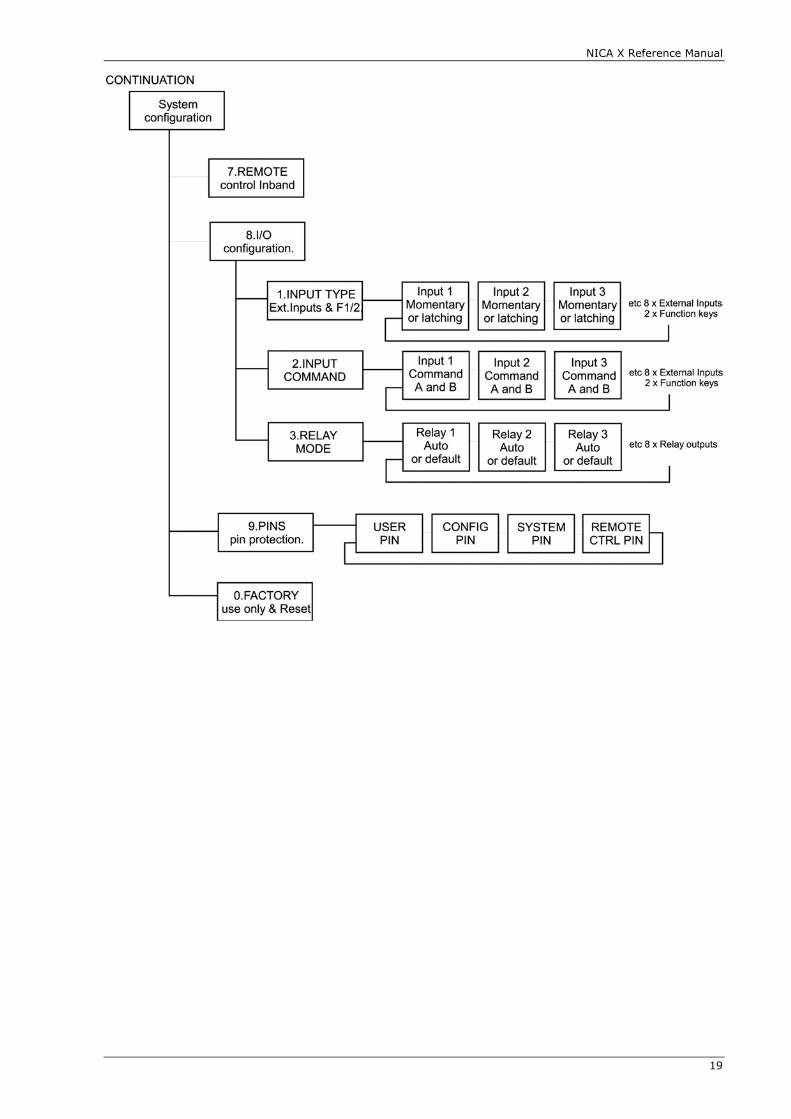
NICA X Reference Manual
19
NICA X Reference Manual
20
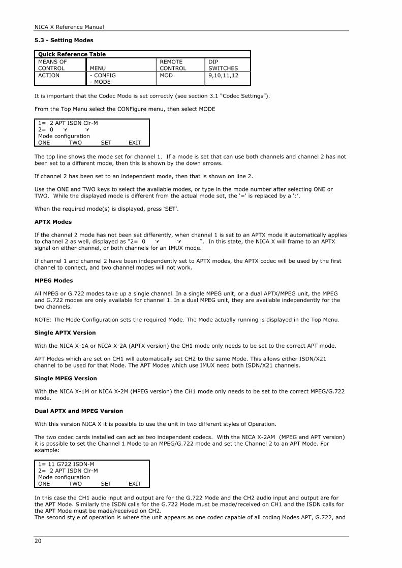
5.3 - Setting Modes
Quick Reference TableMEANS OFCONTROL MENU
REMOTECONTROL
DIPSWITCHES
ACTION - CONFIG- MODE
MOD 9,10,11,12
It is important that the Codec Mode is set correctly (see section 3.1 “Codec Settings”).
From the Top Menu select the CONFigure menu, then select MODE
1= 2 APT ISDN Clr-M2= 0 Mode configurationONE TWO SET EXIT
The top line shows the mode set for channel 1. If a mode is set that can use both channels and channel 2 has notbeen set to a different mode, then this is shown by the down arrows.
If channel 2 has been set to an independent mode, then that is shown on line 2.
Use the ONE and TWO keys to select the available modes, or type in the mode number after selecting ONE orTWO. While the displayed mode is different from the actual mode set, the ‘=‘ is replaced by a ‘:’.
When the required mode(s) is displayed, press ‘SET’.
APTX Modes
If the channel 2 mode has not been set differently, when channel 1 is set to an APTX mode it automatically appliesto channel 2 as well, displayed as “2= 0 “. In this state, the NICA X will frame to an APTXsignal on either channel, or both channels for an IMUX mode.
If channel 1 and channel 2 have been independently set to APTX modes, the APTX codec will be used by the firstchannel to connect, and two channel modes will not work.
MPEG Modes
All MPEG or G.722 modes take up a single channel. In a single MPEG unit, or a dual APTX/MPEG unit, the MPEGand G.722 modes are only available for channel 1. In a dual MPEG unit, they are available independently for thetwo channels.
NOTE: The Mode Configuration sets the required Mode. The Mode actually running is displayed in the Top Menu.
Single APTX Version
With the NICA X-1A or NICA X-2A (APTX version) the CH1 mode only needs to be set to the correct APT mode.
APT Modes which are set on CH1 will automatically set CH2 to the same Mode. This allows either ISDN/X21channel to be used for that Mode. The APT Modes which use IMUX need both ISDN/X21 channels.
Single MPEG Version
With the NICA X-1M or NICA X-2M (MPEG version) the CH1 mode only needs to be set to the correct MPEG/G.722mode.
Dual APTX and MPEG Version With this version NICA X it is possible to use the unit in two different styles of Operation.
The two codec cards installed can act as two independent codecs. With the NICA X-2AM (MPEG and APT version)it is possible to set the Channel 1 Mode to an MPEG/G.722 mode and set the Channel 2 to an APT Mode. Forexample: 1= 11 G722 ISDN-M2= 2 APT ISDN Clr-MMode configurationONE TWO SET EXIT
In this case the CH1 audio input and output are for the G.722 Mode and the CH2 audio input and output are forthe APT Mode. Similarly the ISDN calls for the G.722 Mode must be made/received on CH1 and the ISDN calls forthe APT Mode must be made/received on CH2.The second style of operation is where the unit appears as one codec capable of all coding Modes APT, G.722, and
NICA X Reference Manual
21
MPEG. In this case the Channel 1 mode is just used with Channel 2 mode always set to “0 - NONE SET”. The audiowill appear on CH1 input and output (or CH2 as well if a stereo mode is used).
APT Modes which are set on CH1 will automatically set CH2 to the same Mode. This allows either ISDN/X21channel to be used for that Mode. The APT Modes which use IMUX need both ISDN /X21 channels.
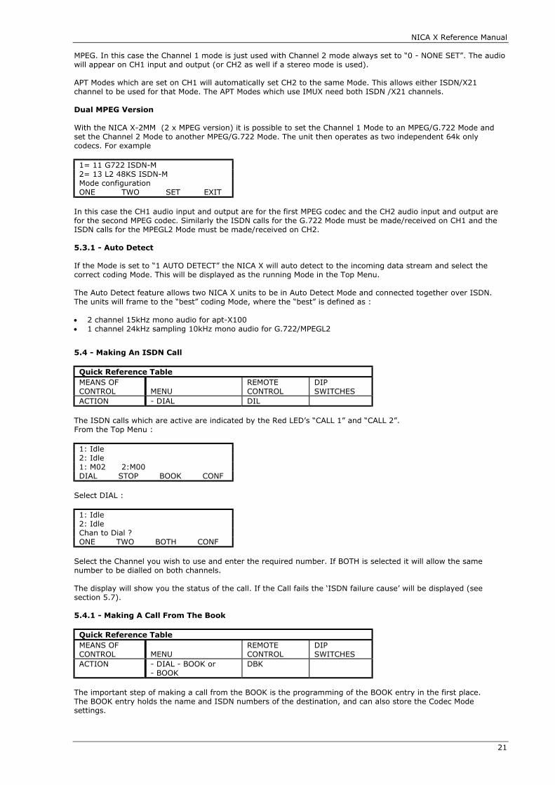
Dual MPEG Version With the NICA X-2MM (2 x MPEG version) it is possible to set the Channel 1 Mode to an MPEG/G.722 Mode andset the Channel 2 Mode to another MPEG/G.722 Mode. The unit then operates as two independent 64k onlycodecs. For example
1= 11 G722 ISDN-M2= 13 L2 48KS ISDN-MMode configurationONE TWO SET EXIT
In this case the CH1 audio input and output are for the first MPEG codec and the CH2 audio input and output arefor the second MPEG codec. Similarly the ISDN calls for the G.722 Mode must be made/received on CH1 and theISDN calls for the MPEGL2 Mode must be made/received on CH2.
5.3.1 - Auto Detect
If the Mode is set to “1 AUTO DETECT” the NICA X will auto detect to the incoming data stream and select thecorrect coding Mode. This will be displayed as the running Mode in the Top Menu.
The Auto Detect feature allows two NICA X units to be in Auto Detect Mode and connected together over ISDN.The units will frame to the “best” coding Mode, where the “best” is defined as :
• 2 channel 15kHz mono audio for apt-X100• 1 channel 24kHz sampling 10kHz mono audio for G.722/MPEGL2
5.4 - Making An ISDN Call
Quick Reference TableMEANS OFCONTROL MENU
REMOTECONTROL
DIPSWITCHES
ACTION - DIAL DIL
The ISDN calls which are active are indicated by the Red LED’s “CALL 1” and “CALL 2”.From the Top Menu :
1: Idle2: Idle1: M02 2:M00DIAL STOP BOOK CONF
Select DIAL :
1: Idle2: IdleChan to Dial ?ONE TWO BOTH CONF
Select the Channel you wish to use and enter the required number. If BOTH is selected it will allow the samenumber to be dialled on both channels.
The display will show you the status of the call. If the Call fails the ‘ISDN failure cause’ will be displayed (seesection 5.7).
5.4.1 - Making A Call From The Book
Quick Reference TableMEANS OFCONTROL MENU
REMOTECONTROL
DIPSWITCHES
ACTION - DIAL - BOOK or- BOOK
DBK
The important step of making a call from the BOOK is the programming of the BOOK entry in the first place.The BOOK entry holds the name and ISDN numbers of the destination, and can also store the Codec Modesettings.

NICA X Reference Manual
22
To make a call from the BOOK select BOOK from the Top Menu and then select the required BOOK entry by eitherusing the PREVious and NEXT keys or by simply typing in the number.
1: Idle2: Idle3>WRFMPREV NEXT DIAL CONF
Once the required entry is displayed press the DIAL key and the codec Mode will be set (if programmed) and theISDN numbers will be dialled. Once connected, the name of the Book entry will then be displayed.
When a BOOK entry is cleared, the codec Mode is set back to the default Mode.
The BOOK menu can also be accessed from DIAL-ONE-BOOK or DIAL-TWO-BOOK and then only the chosenchannel will be dialled.
5.4.2 - Making A Call With A Sub-Address
Quick Reference TableMEANS OFCONTROL MENU
REMOTECONTROL
DIPSWITCHES
ACTION - DIAL DIL
To make a call with a sub-address extension simply enter # and up to a three digit sub-address after the numbere.g. 09713889044#344 dials with a sub-address 344.The equipment with sub-address 344 connected to 09713889044 will answer the call.
The Sub-address is used to filter calls to the correct port or terminal equipment on an ISDN line. The remoteterminal equipment must have a sub-address defined. An incoming call with a sub-address element present will bechecked against the sub-address defined. If they match, the call will be answered. If they do not match, the callwill not be answered. If the remote equipment does not have a sub-address set, or if the sub-address element isnot presented by the ISDN network, the call will be accepted.
5.5 - Clearing A Call – Stop
Quick Reference TableMEANS OFCONTROL MENU
REMOTECONTROL
DIPSWITCHES
ACTION - STOP STP
To clear a single call select STOP and then either channel ONE, TWO or BOTH. The display will show ' Call clearing',the call will be cleared down and the Call LED will turn off.
By selecting STOP and BOTH, both channel one and two will be cleared one after the other.
5.6 - Answering A Call
The unit will always auto answer a call if a channel is free as long as the Call Permit configuration condition is met(see section 4.5). When a call is answered and connected, the relevant Call LED will be illuminated and the displaywill show ‘IN’ and the Calling Party Number (CPN), if provided. If the CPN matches a number stored in a BOOKentry then the name of the book entry will be displayed.
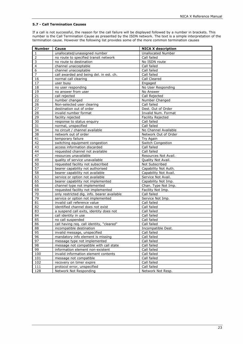
NICA X Reference Manual
23
5.7 - Call Termination Causes
If a call is not successful, the reason for the call failure will be displayed followed by a number in brackets. Thisnumber is the Call Termination Cause as presented by the ISDN network. The text is a simple interpretation of thetermination cause. However the following list provides some of the more common termination causes
Number Cause NICA X description1 unallocated/unassigned number Unallocated Number2 no route to specified transit network Call failed3 no route to destination No ISDN route4 channel unacceptable Call failed6 channel unacceptable Call failed7 call awarded and being del. in est. ch. Call failed16 normal call clearing Call Cleared17 user busy Engaged18 no user responding No User Responding19 no answer from user No Answer21 call rejected Call Rejected22 number changed Number Changed26 Non-selected user clearing Call failed27 destination out of order Dest. Out of Order28 invalid number format Invalid Num. Format29 facility rejected Facility Rejected30 response to status enquiry Call failed31 normal, unspecified Call failed34 no circuit / channel available No Channel Available38 network out of order Network Out of Order41 temporary failure Try Again42 switching equipment congestion Switch Congestion43 access information discarded Call failed44 requested channel not available Call failed47 resources unavailable Resources Not Avail.49 quality of service unavailable Quality Not Avail.50 requested facility not subscribed Not Subscribed57 bearer capability not authorised Capability Not Auth.58 bearer capability not available Capability Not Avail.63 service or option not available Service Not Avail.65 bearer capability not implemented Capability Not Imp.66 channel type not implemented Chan. Type Not Imp.69 requested facility not implemented Facility Not Imp.70 only restricted dig. info. bearer available Call failed79 service or option not implemented Service Not Imp.81 invalid call reference value Call failed82 identified channel does not exist Call failed83 a suspend call exits, identity does not Call failed84 call identity in use Call failed85 no call suspended Call failed86 call having req. call identity, "cleared" Call failed88 incompatible destination Incompatible Dest.95 invalid message, unspecified Call failed96 mandatory info element is missing Call failed97 message type not implemented Call failed98 message not compatible with call state Call failed99 information element non-existent Call failed100 invalid information element contents Call failed101 message not compatible Call failed102 recovery on timer expire Call failed111 protocol error, unspecified Call failed128 Network Not Responding Network Not Resp.

NICA X Reference Manual
24
5.8 - Book Entries
Quick Reference TableMEANS OFCONTROL MENU
REMOTECONTROL
DIPSWITCHES
ACTION - CONF- BOOK- ADD/EDIT/DEL
BKE
To Add a new BOOK entry, or to Edit or Delete an existing entry, select BOOK from the configuration menu.
1: Idle2: IdleEdit book ADD EDIT DEL EXIT
Select ADD to add a new entry or EDIT or DELETE.
Book Entry Structure
Each entry has an ID number, a name (12 characters), a number for Channel 1, and a number for Channel 2(each 24 digits). The optional settings in the BOOK entry are the codec Mode to be used, the Data Rate of theISDN, and the Auxiliary Data setting.
If the Mode of the codec is set in a book entry, when the book entry is used the Mode may be changed from thecurrent default Mode. Therefore, when the BOOK entry is then cleared down, the Mode will be set back to thedefault.
If the NICA X is used as two independent codecs, for example an MPEG/G.722 codec on channel 1 and an APTXcodec on channel two, it is important when the book entries are programmed that the ISDN number isprogrammed into the correct channel, i.e. channel 1 for MPEG/G.722 book entries and channel 2 for APT bookentries.

NICA X Reference Manual
25
CHAPTER 6 BACKUP OPERATION
Quick Reference TableMEANS OFCONTROL MENU
REMOTE CONTROL DIPSWITCHES
ACTION - SYSTEM-CONFIG- 2. BACKUP
CBG, CBM, CBP,CBR, CBE, CBI, CBS
2
The NICA X has a separate mode of operation for performing the backup for a primary service.There are two scenarios :-
1. Operation as a Primary and Reserve service on one codec.2. Operation as a Reserve service to an external Primary service on a different codec.
When running in Backup mode there is a main programme loop as follows :-
A. Primary Service to
B. Primary Service Failto
C. Reserve Serviceto
D. Primary Service Restored or Reserve Service Failed/Stoppedto
A. Primary Service
6.1 – Custom Applications
As well as the Backup Operation the NICA X software version 2.10 onwards also has an additional operating modecalled “SM2”. This “State Machine 2” is a special mode of operation developed for a specific application nowavailable in the NICA X.The Operation of SM2 is detailed in section 6.6 State Machine 2
6.2 - Backup Configuration
The unit has to be programmed correctly to operate in the required scenario. There are a number of variables inthe programming to allow users to fine tune their operation. The table below gives an overview of this.
Parameter OptionsBackup Enable NORMAL/BACKUP/SM2Primary Mode Any codec mode or none set (none set indicates primary service is external)Primary Channel 0, 1, 2, 1or2, 1&2 Primary No.s ch1, ch2 ISDN numbers (If primary Mode is on ISDN)Reserve Mode Any codec modeReserve Channel 0, 1, 2, 1or2, 1&2Reserve No.s ch1, ch2 ISDN numbers A and B (B are alternative backup numbers) Fail Detect external/frame/audio1/audio1or2/audio1&2/ind1/ind2/ind1or2/ind1&2Restore Detect external/frame/audio1/audio1or2/audio1&2/ind1/ind2/ind1or2/ind1&2Down Time 0 - 255 secondsUp Time 0 - 255 secondsSilence Level -24dB/-12dB/-6dB/0dBNumber of Retries 0 - 6Monitor Function ON/OFFMonitor Time 0 - 5 minutes
Backup Enable
If set to BACKUP this sets the NICA X into Backup operation mode. Set this to BACKUP once all your other settingsare correct. A Remote Control Command CBE can also be used to change this setting (this could be programmedinto an Opto Input or a Function Key). The SM2 setting is a custom state machine as described in section 6.6
Primary Mode
If the NICA X is providing the Primary and Reserve service then the Primary Codec Mode is set here. It could beany valid mode from the codec mode list. If the NICA X is providing a Reserve service to an external Primary service then the mode must be set to “ NONESET”.
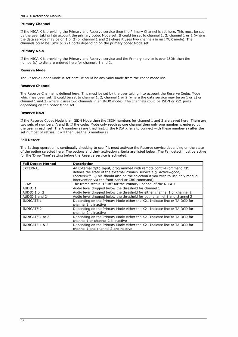
NICA X Reference Manual
26
Primary Channel
If the NICA X is providing the Primary and Reserve service then the Primary Channel is set here. This must be setby the user taking into account the primary codec Mode set. It could be set to channel 1, 2, channel 1 or 2 (wherethe data service may be on 1 or 2) or channel 1 and 2 (where it uses two channels in an IMUX mode). Thechannels could be ISDN or X21 ports depending on the primary codec Mode set.
Primary No.s
If the NICA X is providing the Primary and Reserve service and the Primary service is over ISDN then thenumber(s) to dial are entered here for channels 1 and 2.
Reserve Mode
The Reserve Codec Mode is set here. It could be any valid mode from the codec mode list.
Reserve Channel
The Reserve Channel is defined here. This must be set by the user taking into account the Reserve Codec Modewhich has been set. It could be set to channel 1, 2, channel 1 or 2 (where the data service may be on 1 or 2) orchannel 1 and 2 (where it uses two channels in an IMUX mode). The channels could be ISDN or X21 portsdepending on the codec Mode set.
Reserve No.s
If the Reserve Codec Mode is an ISDN Mode then the ISDN numbers for channel 1 and 2 are saved here. There aretwo sets of numbers, A and B. If the codec Mode only requires one channel then only one number is entered bythe user in each set. The A number(s) are tried first. If the NICA X fails to connect with these number(s) after theset number of retries, it will then use the B number(s)
Fail Detect
The Backup operation is continually checking to see if it must activate the Reserve service depending on the stateof the option selected here. The options and their activation criteria are listed below. The Fail detect must be activefor the ‘Drop Time’ setting before the Reserve service is activated.
Fail Detect Method DescriptionEXTERNAL An External Opto Input, programmed with remote control command CBI,
defines the state of the external Primary service e.g. Active=good,Inactive=fail (This should also be the selection if you wish to use only manualintervention via the front panel or CBS command)
FRAME The frame status is “Off” for the Primary Channel of the NICA XAUDIO 1 Audio level dropped below the threshold for channel 1AUDIO 1 or 2 Audio level dropped below the threshold for either channel 1 or channel 2AUDIO 1 and 2 Audio level dropped below the threshold for both channel 1 and channel 2INDICATE 1 Depending on the Primary Mode either the X21 Indicate line or TA DCD for
channel 1 is inactiveINDICATE 2 Depending on the Primary Mode either the X21 Indicate line or TA DCD for
channel 2 is inactiveINDICATE 1 or 2 Depending on the Primary Mode either the X21 Indicate line or TA DCD for
channel 1 or channel 2 is inactiveINDICATE 1 & 2 Depending on the Primary Mode either the X21 Indicate line or TA DCD for
channel 1 and channel 2 are inactive

NICA X Reference Manual
27
Restore DetectIf the Reserve service is active then the Restore Detect selection is continually checked to see if the NICA X mustswitch back to the Primary service. The options and their criteria are listed below. The Restore Detect must beactive for the ‘Up Time’ setting before the Reserve service is de-activated.
Restore Detect Method DescriptionEXTERNAL An External Opto Input programmed with remote control command CBI
defines the state of the external Primary service e.g.Active=good Inactive=fail(This should also be the selection if you wish to use only manual interventionvia the front panel or CBS command)
FRAME The frame status is on for the Primary Channel of the NICA X.AUDIO 1 Audio level above the threshold for channel 1AUDIO 1 or 2 Audio level above the threshold for either channel 1 or channel 2AUDIO 1 and 2 Audio level above the threshold for both channel 1 and channel 2INDICATE 1 Depending on the Primary Mode either the X21 Indicate line or TA DCD for
channel 1 is activeINDICATE 2 Depending on the Primary Mode either the X21 Indicate line or TA DCD for
channel 2 is activeINDICATE 1 or 2 Depending on the Primary Mode either the X21 Indicate line or TA DCD for
channel 1 or channel 2 is activeINDICATE 1 & 2 Depending on the Primary Mode either the X21 Indicate line or TA DCD for
channel 1 and channel 2 are active
Down Time
When the Primary service is operating this is the value reloaded into the countdown timer while Fail Detect is false.While the Fail Detect is true the system timer will count down. If the timer expires then the Reserve service will beactivated. If the Reserve service is activated but fails to connect or frame the system reverts to trying the Primaryservice.
Up Time
When the Reserve service is operating this is the value reloaded into the countdown timer while Restore Detect isfalse. While the Restore Detect is true the timer will count down. If the timer expires then the Primary service willbe activated.
Silence Level
The silence detector level is programmable at -24dBu, -18dBu, -12dBu or -6dBu (±1.5dBu). When the audio inputinto the detector drops to this level then silence is said to be detected. Number of Retries
This is the number of retries the NICA X performs when dialling the Backup ISDN numbers before switching backto standby or Primary service.
Monitor Enable
When the unit goes into Reserve service it will route its output audio into the codec section audio input if themonitor is enabled. This means the remote codec involved in the backup can monitor the actual audio output ofthe NICA X. (This feature requires the audio switch module).
Monitor Time
This is the length of time the audio is switched for monitoring as above.
Front Panel Control & Remote Command Control
The Front Panel keys PRIMary and REServe (for NICA X-2) and the Remote Control Command CBS (which could beprogrammed into a Function key or Opto Input) are manual ways of switching between the Primary and Reserveservice. This is sometimes the only way to switch back to Primary if the NICA X is providing the Primary andReserve service.
6.3 - Backup Display - NICA X-2 only
When the NICA X is set to BACKUP ENABLE - ON the display of the NICA X-2 shows the Backup Status Menu. Thetwo keys Primary and Reserve allow the state of the system to be changed between Primary and ReserveOperation. This is protected by the Config PIN entry.
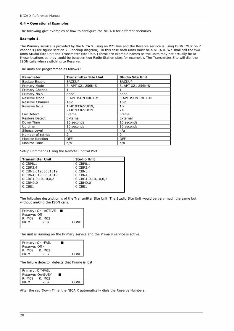
NICA X Reference Manual
28
6.4 – Operational Examples
The following give examples of how to configure the NICA X for different scenarios.
Example 1
The Primary service is provided by the NICA X using an X21 line and the Reserve service is using ISDN IMUX on 2channels (see figure section 7.3 backup diagram). In this case both units must be a NICA X. We shall call the twounits Studio Site Unit and Transmitter Site Unit. (These are example names as the units may not actually be atthese locations as they could be between two Radio Station sites for example). The Transmitter Site will dial theISDN calls when switching to Reserve.
The units are programmed as follows :
Parameter Transmitter Site Unit Studio Site UnitBackup Enable BACKUP BACKUPPrimary Mode 8. APT X21 256K-S 8. APT X21 256K-SPrimary Channel 1 1 Primary No.s none noneReserve Mode 3.APT ISDN IMUX-M 3.APT ISDN IMUX-MReserve Channel 1&2 1&2Reserve No.s 1>01933651819,
2>019336518191>2>
Fail Detect Frame FrameRestore Detect External ExternalDown Time 10 seconds 10 secondsUp time 10 seconds 10 secondsSilence Level n/a n/aNumber of retries 2 0Monitor function OFF OFFMonitor Time n/a n/a
Setup Commands Using the Remote Control Port :
Transmitter Unit Studio Unit0:CBP8,10:CBR3,40:CBN3,019336518190:CBN4,019336518190:CBG1,0,10,10,0,20:CBM0,00:CBE1
0:CBP8,10:CBR3,40:CBN3,0:CBN4,0:CBG1,0,10,10,0,20:CBM0,00:CBE1
The following description is of the Transmitter Site Unit. The Studio Site Unit would be very much the same butwithout making the ISDN calls.
Primary: On -ACTIVE ■Reserve: OffP: M08 R: M03PRIM RES CONF
The unit is running on the Primary service and the Primary service is active.
Primary: On -FAIL ■Reserve: Off - P: M08 R: M03PRIM RES CONF
The failure detector detects that Frame is lost
Primary: Off-FAILReserve: On-BUSY ■P: M08 R: M03PRIM RES CONF
After the set ‘Down Time’ the NICA X automatically dials the Reserve Numbers.

NICA X Reference Manual
29
Primary: Off-Reserve: On-ACTIVE ■P: M08 R: M03PRIM RES CONF
The unit is running on the Reserve service and the Reserve service is active.
Primary: Off-Reserve: On - ACTIVE ■P: M08 R: M03PRIM RES CONF
The restore detector detects that External input has occurred. (or if manually forced by front panel keys or remotecontrol command).
Primary: On - ACTIVE ■Reserve: Off - P: M08 R: M03PRIM RES CONF
After the set ‘Up Time’ the NICA X automatically switches to the Primary service and clears the calls associatedwith the Reserve service.
Example 2
The Primary service is provided by the NICA X on X21 port 1 and the Reserve service is on X21 port 2. The unit isprogrammed as follows.
The remote units for Primary and Reserve do not have to be NICA X units, or the same unit, as long as they areset to compatible coding Modes. If separate units were used for Primary and Reserve they would not have to be inBackup Mode. If the same NICA X unit was used remotely to provide Primary and Reserve then it would have to bein Backup Mode with the same settings as below.
Parameter SettingBackup Enable BACKUPPrimary Mode 8. APT X21 256K-SPrimary Channel 1 Primary No.s n/aReserve Mode 8. APT X21 256K-SReserve Channel 2Reserve No.s n/a Fail Detect Indicate 1Restore Detect Indicate 1Down Time 10 secondsUp time 10 secondsSilence Level n/aNumber of Retries n/aMonitor Function OFFMonitor Time n/a
Setup Commands Using the Remote Control Port :0:CBP8,10:CBR8,20:CBG5,5,10,10,0,00:CBM0,00:CBE1
Primary: On -ACTIVE ■Reserve: OffP: M08 R: M08PRIM RES CONF
The unit is running on the Primary service and the Primary service is active.
Primary: On -FAIL ■Reserve: Off - P: M08 R: M08PRIM RES CONF
The failure detector detects that Indicate 1 has failed

NICA X Reference Manual
30
Primary: Off-FAILReserve: On -ACTIVE ■P: M08 R: M08PRIM RES CONF
After the set ‘Down Time’ the NICA X automatically switches to the Reserve service.
Primary: Off-Reserve: On -ACTIVE ■P: M08 R: M08PRIM RES CONF
The unit is running on the Reserve service and the Reserve service is active.
Primary: Off-Reserve: On -ACTIVE ■P: M08 R: M08PRIM RES CONF
The restore detector detects that Indicate 1 has restored.
Primary: On -ACTIVE ■Reserve: Off - P: M08 R: M08PRIM RES CONF
After the set ‘Up Time’ the NICA X automatically switches back to the Primary service.
Example 3
The Primary service is provided by an external system and the Reserve service is provided by the NICA X usingISDN IMUX on 2 channels (see figure section 7.4 backup diagram). In this example the Audio Switch Module(option) is fitted.
The Audio Programme feed from the primary external service is input into the CH1 and CH2 input connectors ofthe NICA X and the Audio Switch Module loops this through to the output connectors of the NICA X. The Relays onthe audio switch module rest in this routing position so if the NICA X fails the programme feed is still routed asrequired.
The remote unit to provide the other end of the Reserve does not have to be a NICA X unit as long as it is set to acompatible coding Mode. If a NICA X is used, it must not be set in Backup Mode, but just in the compatible codingMode.

NICA X Reference Manual
31
The NICA X is programmed as follows :
Parameter SettingBackup Enable BACKUPPrimary Mode 0.NONE SETPrimary Channel n/aPrimary No.s n/aReserve Mode 3.APT ISDN IMUX-MReserve Channel 1&2Reserve No.s 1>01933651819, 2>01933651819 Fail Detect AUDIO1&2Restore Detect AUDIO1&2Down Time 10 secondsUp time 10 secondsSilence Level -24dBuNumber of Retries 2Monitor Function OFFMonitor Time n/a
Setup Commands Using the Remote Control Port0:CBP0,00:CBR3,40:CBN3,019336518190:CBN4,019336518190:CBG4,4,10,10,3,20:CBM0,00:CBE1
Primary: On -ACTIVE ■Reserve: OffP: M00 R: M03PRIM RES CONF
The unit is monitoring the Primary service and the Primary service is active.
Primary: On -FAIL ■Reserve: Off - P: M00 R: M03PRIM RES CONF
The failure detector detects that Audio has failed on channels 1 and 2.
Primary: Off-FAILReserve: On-BUSY ■P: M00 R: M03PRIM RES CONF
After the set ‘Down Time’ the NICA X automatically dials the Reserve Numbers.
Primary: Off-Reserve: On-ACTIVE ■P: M00 R: M03PRIM RES CONF
The unit is running on the Reserve service and the Reserve service is active.
Primary: Off-Reserve: On -ACTIVE ■P: M00 R: M03PRIM RES CONF
The restore detector detects that Audio has been restored on channels 1 and 2.
Primary: On -ACTIVE ■Reserve: Off - P: M00 R: M03PRIM RES CONF
After the set ‘Up Time’ the NICA X automatically switches to monitoring the Primary service and clears the callsassociated with the Reserve service.
NICA X Reference Manual
32
6.5 - Audio Switch Module (Optional)
The Audio Switch Module is an optional module fitted internally and is required for operational scenarios that useaudio testing for the fail and restore detectors. It is capable of performing a number of audio switching functions
The Input Audio Connector can be Routed to the Output Audio Connector for Backup options where the PrimaryService is external and the Reserve Service is provided by the NICA X Codec (see figure section 7.4 backupdiagram).
The Output Audio Connector can be routed internally to the Silence detector (without this module only the InputAudio Connector can be routed to the Silence Detector.
The Monitor Function used in Reserve service operation allows the Audio Input Connector to be Routed to theAudio Output Connector but also the Audio Output Connector to be routed to the audio input of the codec to sendto the remote reserve codec.
Issue 2 Audio Switch Modules have the facility to sum the Left and Right audio input. When the main mode is setto Mono (i.e. Main mode Mono and no secondary mode or breakout). This is useful when using the Backup modewhen the Primary service is stereo with a mono backup service.
6.6 – State Machine 2
The SM2 (State Machine 2) mode of BACKUP is a custom mode of operation developed for a specific application. Itis designed to operate with a Local and Remote NICA X model 2MM to give two independent G722 audio channelsfrom the Remote unit to the Local Unit. The return audio path is not used. The two audio channels are described asChannel 1 and Channel 2
General Definitions :
Channel 1 controlled by Local end unit opto input 1 (External Input connector)Channel 2 controlled by Local end unit opto input 2 (External Input connector)
Channel 1 Remote Relay contact at Remote end unit Relay 3 (External Input connector)Channel 2 Remote Relay contact at Remote end unit Relay 4 (External Input connector)
Channel 1 Alarm relay contact at Local end unit Relay 6 (External Output connector)Channel 2 Alarm relay contact at Local end unit Relay 7 (External Output connector)
("On" = Current flowing through opto isolator / relay contact closed);
Operation Under Control Scenario :
Channel 1 "on"
Dial up Remote unit and Operate Remote relay for Channel 1 (Relay3);
Channel 2 "on"
Dial up Remote unit and Operate Remote relay for Channel 2 (Relay4);;
Channel 1 "off"
Turn off Remote unit Channel 1 relay (Relay3), wait approximately 10 seconds before disconnection. If channel 1is turned back "on" within the 10 seconds leave connected and reset the timer;
Channel 2 "off"
Turn off Remote unit Channel 2 relay (Relay4), wait approximately 10 seconds before disconnection. If channel 1is turned back "on" within the 10 seconds leave connected and reset the timer;
Operation Under Fault or Error Conditions :No redial attempts.Call Drop Out:Close Local unit alarm relay contact, do not automatically redial. Alarm relay to be open circuit when Channelcontrol is "off";
At remote end unit if no connection or after a call drop out etc. turn "off" Remote end Relays for Channel 1 and 2.
6.6.1 - Operating States
In this operating mode, each channel has its own controlling state machine. The major states are :
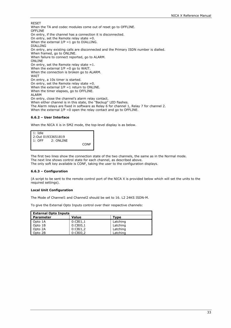
NICA X Reference Manual
33
RESETWhen the TA and codec modules come out of reset go to OFFLINE.OFFLINEOn entry, if the channel has a connection it is disconnected.On entry, set the Remote relay state =0.When the external I/P =1 go to DIALLING.DIALLINGOn entry, any existing calls are disconnected and the Primary ISDN number is dialled.When framed, go to ONLINE.When failure to connect reported, go to ALARM.ONLINEOn entry, set the Remote relay state =1.When the external I/P =0 go to WAIT.When the connection is broken go to ALARM.WAITOn entry, a 10s timer is started.On entry, set the Remote relay state =0.When the external I/P =1 return to ONLINE.When the timer elapses, go to OFFLINE.ALARMOn entry, close the channel’s alarm relay contact.When either channel is in this state, the "Backup" LED flashes.The Alarm relays are fixed in software as Relay 6 for channel 1, Relay 7 for channel 2.When the external I/P =0 open the relay contact and go to OFFLINE.
6.6.2 – User Interface
When the NICA X is in SM2 mode, the top-level display is as below.
1: Idle2:Out 019336518191: OFF 2: ONLINE CONF
The first two lines show the connection state of the two channels, the same as in the Normal mode.The next line shows control state for each channel, as described above.The only soft key available is CONF, taking the user to the configuration displays.
6.6.3 – Configuration
(A script to be sent to the remote control port of the NICA X is provided below which will set the units to therequired settings).
Local Unit Configuration
The Mode of Channel1 and Channel2 should be set to 16. L2 24KS ISDN-M.
To give the External Opto Inputs control over their respective channels:
External Opto InputsParameter Value TypeOpto 1A 0:CBI1,1 LatchingOpto 1B 0:CBI0,1 LatchingOpto 2A 0:CBI1,2 LatchingOpto 2B 0:CBI0,2 Latching

NICA X Reference Manual
34
The F1 and F2 buttons could be programmed in the same way to give front panel control. To configure the mode of operation :
Backup Parameter SettingsParameter ValueBackup Mode SM2 (i.e. 2)Primary Mode n/a Primary Channel n/aPrimary No.s valid ISDN number
valid ISDN numberReserve Mode n/aReserve Channel n/aReserve No.s * empty
emptyFail Detect * EXTERNALRestore Detect * EXTERNALDown Time 10 sUp Time * 0Silence Level n/aNumber of Retries * 0Monitor Function * OFFMonitor Time * n/a
Settings for the parameters marked “*” may or may not affect operation, and operation can only be guaranteedwith them set as shown.
Remote Unit Configuration
The Mode of Channel1 and Channel2 should be set to 15. G722 ISDN-M.
To give the codecs' signal bits control over their respective relays:
External I/P BitsParameter Value TypeSignal 1A 0:REL3,1 LatchingSignal 1B 0:REL3,0 LatchingSignal 2A 0:REL4,1 LatchingSignal 2B 0:REL4,0 Latching
Configuration Scripts (Sent to a unit in factory defaults) :
Local Unit Remote Unit0:EXI0,"0:CBI1,1",10:EXI1,"0:CBI0,1",10:EXI2,"0:CBI1,2",10:EXI3,"0:CBI0,2",10:MOD16,160:CBG0,0,10,0,0,00:CBM0,00:CBN1,3840000:CBN2,3840100:CBE2
0:EXI20,"0:REL3,1",10:EXI21,"0:REL3,0",10:EXI22,"0:REL4,1",10:EXI23,"0:REL4,0",10:MOD15,15

NICA X Reference Manual
35
CHAPTER 7 APPLICATION DIAGRAMS

NICA X Reference Manual
36
NICA X Reference Manual
37
NICA X Reference Manual
38
NICA X Reference Manual
39

NICA X Reference Manual
40
CHAPTER 8 REMOTE CONTROL PROTOCOL
8.1 - Revision
This chapter is Revision 3 of the remote control specification.
8.2 - Introduction
The remote control port provides full control of the NICA X. All operations available from the front panel areavailable through this port with the exception of Factory Level commands.
For brevity, the remote control device has been referred to throughout this document as a “PC”, but obviously thisis all just as relevant for any computer system using RS232 communications.
If the NICA X unit is linked to a NICA X unit at the far end then it is possible to control the functions of the far endunit through the inband data channel if this feature has been enabled.
8.3 - Protocol
The character format is fixed at 9600 baud, no parity, 8 data bits and 1 stop bit.
All messages to the NICA X consist of up to 84 characters followed by either a CR, or by ETX BCC, where BCC isthe exclusive OR sum of all characters in the message and 0xff.
The NICA X always answers within 7 seconds and never transmits except in answer to a received message. Theend style sent by the NICA X matches that received; if no valid end was detected, no answer is sent.
The PC must not start sending another message until the last character of the previous response has been fullyreceived, or 7 seconds have elapsed since the last message was sent and no reply was received.
All commands consist of the following :
Unit ID - 0 for local unit, 1 for far end unit.
‘:’
Command mnemonic- three character upper case alpha numeric, from the list below.
Parameter list- the number of parameters and their meaning are command dependent. Parameters are separatedby a comma. Empty parameters can be signalled by the lack of data between commas, or empty parameters atthe end of a parameter list can be omitted if the command allows. Any non-printing character other than CR orETX is just stripped as white space, but must not appear within a parameter. Name parameters, e.g. book names,must be enclosed within quote marks and can contain spaces as valid characters.
Responses consist of the following :
A decimal response code.If required, a comma followed by a returned result list with parameters separated by commas.

NICA X Reference Manual
41
8.4 - Command List
Activate Relay (REL)DESCRIPTION: Activate a given relay output.SYNTAX: <unit id>:REL <relay no>,<en>RESPONSE: <respcode>,<relay number>,<en>PARAMETERS:<relay no> = a valid relay number ( 1 to 8 ).<en> = 0 - turn relay off, 1 - turn relay on.EXAMPLE:(PC) 0:REL1,1↵(NX) 00↵
Answer Call (ANS)DESCRIPTION: Answer a call for the specified channel.SYNTAX: <unit id>:ANS <channel>RESPONSE: <respcode ( =0 )>PARAMETERS:<unit id> = 0 - local unit, 1- far end unit.<channel> = The channel number ( 1 or 2 ).EXAMPLE:(PC) 0:ANS2↵(NX) 00↵i.e. The NICA X accepts the command.
Book Dial (DBK)DESCRIPTION: Dial a book entry.SYNTAX: <unit id>:DBK <book id>,<channel>RESPONSE: <respcode ( =0 )>PARAMETERS:<book id> = ID number for selected book entry.<channel> = One of: 0-both, 1-chan1, 2-chan2. The channel to use if only want to dial half of book.EXAMPLE:(PC) 0:DBK24↵(NX) 00↵i.e. Dial book entry number 24, the NICA X accepts the command.
Configure Backup - Enable Backup (CBE)DESCRIPTION: Select the backup mode of operation.SYNTAX: <unit id>:CBE <enable>RESPONSE: <respcode>,<enable>PARAMETERS:<enable> = 0 = disable backup operation, 1 = enable backup operation, 2 = enable special SM2 operation.EXAMPLE:(PC) 0:CBE1↵(NX) 00↵i.e. Set the unit into backup mode; the NICA X accepts the command and reports back the current settings.
Configure Backup - External Input (CBI)DESCRIPTION: Indicate the state for the external detectorSYNTAX: <unit id>:CBI <state>, <chno>RESPONSE: <respcode>,<state>PARAMETERS:<state> = 1 - the external input indicator is active, 0 - the external input indicator is inactive.<chno> = optional parameter, specifying the channel number (1 or 2) for operating modes where the channelsare independent (only SM2 at the moment). If omitted, defaults to 1.EXAMPLE:(PC) 0:CBI1↵(NX) 00↵i.e. Set the external input indicator to active; the NICA X accepts the command.
Configure Backup - General Settings (CBG)DESCRIPTION: Configure the general settings for the backup mode of operation.SYNTAX: <unit id>:CBG <f.detect>,<r.detect>,<dtime>,<utime>,<silence>,<retry>RESPONSE: <respcode>,<enable>,<f.detect>,<r.detect>,<dtime>,<utime>,<silence>,<retry>PARAMETERS:<f.detect> = fail detect reason loss of one of :-0:External1: Frame.2: Audio on channel 1.3: Audio on channel 1 or 2.
NICA X Reference Manual
42
4: Audio on channels 1and 25: Indicate on channel 1.6: Indicate on channel 2.7: Indicate on channel 1 or 2.8: Indicate on channel 1 and 2.<r.detect> = restore detect reason restore of one of :-0:External1: Frame.2: Audio on channel 1.3: Audio on channel 1 or 2.4: Audio on channels 1and 25: Indicate on channel 1.6: Indicate on channel 2.7: Indicate on channel 1 or 2.8: Indicate on channel 1 and 2.<d.time> = time for fail detect to be true before switching to backup ( 1 - 99 seconds ).<u.time> = time for restore detect to be true before switching to primary ( 1 - 99 seconds ).<silence> = silence detector level one of0: -6db1: -12db2: -18db3: -24db<retry> = number of retries for dialing ( 0 to 5 ).EXAMPLE:(PC) 0:CBG5,0,10,10,0,2↵(NX) 00,5,0,10,10,0,2↵i.e. Set the fail detect as Indicate on channel 1, restore detect as external, down time of 10 seconds, up time of 10seconds, silence level of 0dB and number of retries to 2; the NICA X accepts the command and reports back thecurrent settings.
Configure Backup - ISDN numbers (CBN)DESCRIPTION: Configure the ISDN numbers for the backup mode of operation.SYNTAX: <unit id>:CBN <id num>,<ISDN number>RESPONSE: <respcode>,<id num>,<ISDN number>PARAMETERS:<id num> = ISDN id number one of :-1 - Primary mode channel 1 number.2 - Primary mode channel 2 number.3 - Reserve mode channel 1 number ( pair A )4 - Reserve mode channel 2 number ( pair A )5 - Reserve mode channel 1 number ( pair B )6 - Reserve mode channel 2 number ( pair B )<isdn number> = ISDN calling line identification number, up to 24 digits.EXAMPLE:(PC) 0:CBN3, 01933651819↵(NX) 00,3, 01933651819↵i.e. Set the Reserve mode channel 1 A number to 01672517120; the NICA X accepts the command and reportsback the current settings.
Configure Backup - Monitor Settings (CBM)DESCRIPTION: Configure the monitor mode settings for the backup mode of operation.SYNTAX: <unit id>:CBM <enable>,<m.time>RESPONSE: <respcode>,<enable>,<m.time>PARAMETERS:<enable> = 0 - monitor off, 1 - monitor on.<m.time> = time that monitor remains active once enabled ( 1 to 5 minutes ).EXAMPLE:(PC) 0:CBM1,1↵(NX) 00,1,1↵i.e. Set the monitor mode on with a time of 1 minute; the NICA X accepts the command and reports back thecurrent settings.
Configure Backup - Primary Settings (CBP)DESCRIPTION: Configure the primary settings for the backup mode of operation.SYNTAX: <unit id>:CBP <mode>,<port>RESPONSE: <respcode>,<mode>,<port>PARAMETERS:<mode> = a valid mode number ( 1 to max modes ) or 0 indicating external Primary Unit.<port> = 0 - none set, 1 - port 1, 2 - port 2, 3 - port 1 or 2, 4 - port 1 & 2 .EXAMPLE:(PC) 0:CBP8,1↵(NX) 00,08,1↵
NICA X Reference Manual
43
i.e. Set the Primary mode to 8 using port 1; the NICA X accepts the command and reports back the currentsetting.
Configure Backup - Reserve Settings (CBR)DESCRIPTION: Configure the reserve settings for the backup mode of operation.SYNTAX: <unit id>:CBB <mode>,<port>RESPONSE: <respcode>,<mode>,<port>PARAMETERS:<mode> = a valid mode number ( 1 to max modes ).<port> = 0 - none set, 1 - port 1, 2 - port 2, 3 - port 1 or 2, 4 - port 1 & 2 .EXAMPLE:(PC) 0:CBR3,4↵(NX) 00,03,4↵i.e. Set the Reserve mode to 3 using ports 1 and 2; the NICA X accepts the command and reports back the currentsettings.
Configure Backup - Switch Backup (CBS)DESCRIPTION: Switch the backup mode of operationSYNTAX: <unit id>:CBS <state>RESPONSE: <respcode>,<state>PARAMETERS:<state> = 1 - Primary service, 0 - Reserve service.EXAMPLE:(PC) 0:CBS1↵(NX) 00↵i.e. Set the unit to switch to the Primary service; the NICA X accepts the command.
Configure Call Timeout Setting (CCT)DESCRIPTION: Configure the call timeout setting.SYNTAX: <unit id>:CCT <timer>,<dial time>RESPONSE: <respcode>,<timer>,<dial time>PARAMETERS:<timer> = one of:0: disable call timer.1 .. 7: set call timer to one of the times shown below.
<timer> value time set1 5 minutes2 10 minutes3 30 minutes4 1 hour5 2 hours6 5 hours
<dial time> = time allowed for TA to establish an ISDN call ( 1 - 99 seconds )EXAMPLE:(PC) 0:CCT4,20↵(NX) 00,4,20↵i.e. Set the unit to timeout after 1 hour, and allow 20 seconds for call out; the NICA X accepts the command andreports back the setting.
Configure System PINS (PST)DESCRIPTION: Configure the security pins used by the system.SYNTAX: <unit id>:PST <user en>,<user pin>,<config en>,<config pin>,<system en>,<system pin>,
<remote en>,<remote pin>RESPONSE: <respcode>,PARAMETERS:<user en> = 0 - disable, 1 - enable<user pin> = 4 digit pin number<config en> = 0 - disable, 1 - enable<config pin> = 4 digit pin number<system en> = 0 - disable, 1 - enable<system pin> = 4 digit pin number<remote en> = 0 - disable, 1 - enable<remote pin> = 4 digit pin numberEXAMPLE:(PC) 0:PST 1,1111,0,2,1,3333,0,4444↵(NX) 00,1,1111,0,2222,1,3333,0,4444↵

NICA X Reference Manual
44
Configure TA - Answer Option (CTA)DESCRIPTION: Configure the TA answer options.SYNTAX: <unit id>:CTA <channel>,<answer mode>RESPONSE: <respcode>,<answer mode>PARAMETERS:<channel> = TA channel : 1 or 2<answer mode> = one of : 0 - none, 1 - all, 2 - book match, 3 - number match, 4 - manual.EXAMPLE:(PC) 0:CTA1,2↵(NX) 00,1,2↵i.e. Set the TA to only answer calls whose CLI matches a book entry ISDN number; the NICA X accepts thecommand.
Configure TA - Call Permit Numbers (CTN)1DESCRIPTION: Configure the numbers used for TA call permitting by numbers.SYNTAX: <unit id>:CTN <number id>, <isdn number>RESPONSE: <respcode>, <number id>, <isdn number>PARAMETERS:<number id> = Call permit number id.<isdn number> = ISDN calling line identification number, up to 24 digits.EXAMPLE:(PC) 0:CTN2, 01933651819↵(NX) 00,2, 01933651819↵i.e. Set the second call permit number to 01933651819; the NICA X accepts the command and reports back thecurrent setting.
Configure TA - Channel Settings (CTC)DESCRIPTION: Configure the channel specific settings for the TA module.SYNTAX: <unit id>:CTC <channel>,<rate>,<msn>,<bmap>,<sub>,<buzz call in>RESPONSE: <respcode>, <channel>,<rate>,<msn>,<bmap>,<sub>,<buzz call in>PARAMETERS:<channel> = TA channel : 1 or 2.<rate> = 0 – NOT SET, 1 - 56k, 2 – 64k, 3 – 64kS<msn> = ISDN multiple subscriber number, up to 24 digits.<bmap> = 0 - B1+2, 1 - B1, 2 - B2.<sub> = ISDN sub address, up to 6 digits.<buzz call in> = 0 - disable buzz, 1 - enable buzz.EXAMPLE:(PC) 0:CTC1,0,,1,123,1↵(NX) 00,1,0,,1,123,1↵i.e. Set channel 1 of the TA to have : 64k data rate, no msn, using B1, with a sub address of 123 and buzz on callsin; the NICA X accepts the command and reports back the current settings.
Edit Book Entry (BKE)DESCRIPTION: Edit the settings for a specified book entry.SYNTAX: <unit id>:BKE <book>,<name>,<number1>,<number2>,<main mode>,<secondary
mode>,<rate>,<aux1>,<aux2>RESPONSE: <respcode>, <book >,<name>,<number1>,<number2>,<main mode>,<secondary
mode>,<rate>,<aux1>,<aux2>PARAMETERS:<book > = NICA X book number ( 1 to max books ).<name> = string up to 12 characters long representing the name of the book entry.<number 1> = ISDN destination number, up to 24 digits.<number 2> = ISDN destination number, up to 24 digits.<main mode> = a valid codec mode number ( 1 to max modes ).<secondary mode> = a valid codec mode number ( 1 to max modes ).<rate> = 0 - none set, 1 - 56k, 2 - 64k, 3 - 64ks.<aux1> = 0 - auxiliary data off, 1 - 1200, 2 - 2400, 3 -4800, 4 - 9600, ? - none set.<aux2> = 0 - auxiliary data off, 1 - 1200, 2 - 2400, 3 -4800, 4 - 9600, ? - none set.EXAMPLE:(PC) 0:BKE7,”SONIFEX”,01933651819,01933651819,13,0,0,0,0↵(NX) 00,7,”SONIFEX”,01933651819,01933651819,13,00,0,0,0↵i.e. Set book entry 7 with name “SONIFEX”, ISDN number 1 - 01933651819, ISDN number 2 - 01933651819,main mode 13, no secondary mode, data rate 64k, auxiliary data off; the NICA X accepts the command andreports back the current settings.
Enable/Disable LoopBack (LBK)DESCRIPTION: Configure the loopback mode of operation.SYNTAX: <unit id>:LBK <loopback>RESPONSE: <respcode>,<loopback>PARAMETERS:

NICA X Reference Manual
45
<loopback> = 0 - off, 1 - on.EXAMPLE:(PC) 0:LBK 1↵(NX) 00,1↵i.e. Set system loopback on; the NICA X accepts the command.
Enable/Disable System Options (OPT)DESCRIPTION: Configure the settings for system options.SYNTAX: <unit id>:OPT <audio>, <x21clk>, <monomix>RESPONSE: <respcode>,<audio>,<x21clk>,<monomix>PARAMETERS:<audio> = 0 - microphone, 1 - line.<x21clk> = 0 - internal clock, 1 - external clock.<monomix> = 0 - left channel for mono, 1 - left and right sum for monoEXAMPLE:(PC) 0:OPT↵(NX) 00,0,1,1↵i.e The NICA X accepts the command and reports back the current settings.
Incoming Calling Line Identification (CLI)DESCRIPTION: Return the CLI for the specified channel.SYNTAX: <unit id>:CLI <channel>RESPONSE: <respcode ( =0 )>,<isdn number>PARAMETERS:<unit id> = 0 - local unit, 1- far end unit.<channel> = The channel number ( 1 or 2 ).<isdn number> = ISDN destination number, up to 24 digits.EXAMPLE:(PC) 0:CLI2↵(NX) 00,01672517120↵i.e. Request the CLI of channel 2; the NICA X accepts the command and reports back the CLI.
Information (INF)DESCRIPTION: Request the product name, revision number and serial number for the systemSYNTAX: <unit id>:INFRESPONSE: <respcode ( =0 )>, <product name>PARAMETERS:<product name> = the name of the product and revision number of the software.EXAMPLE:(PC) 0:INF↵(NX) 00,NICA X 1.2↵i.e. Request product information; the NICA X accepts the command and reports back the product information.
Interface Revision (IFR)DESCRIPTION: The interface revision of the NICA X remote control protocol for this version.SYNTAX: <unit id>:IFR <revision>RESPONSE: <respcode ( =0 )>,<interface revision>,<revision>PARAMETERS:<unit id> = 0 - local unit, 1- far end unit.<revision> = The revision of the protocol that the controlling software knows about.<interface revision> = The interface revision of the NICA X remote control protocol for this version.EXAMPLE:(PC) 0:IFR1↵(NX) 00,2,1↵i.e.Set the revision level at 1; the NICA X accepts the command and reports back that the settings.
Manual Dial (DIL)DESCRIPTION: Manual dial the given ISDN number on the selected TA channel.SYNTAX: <unit id>:DIL <channel>, <isdn number>RESPONSE: <respcode ( =0 )>PARAMETERS:<channel> = TA channel number ( 1 or 2 ).<isdn number> = ISDN destination number, up to 24 digits.EXAMPLE:(PC) 0:DIL1, 01933651819↵(NX) 00↵i.e dial ISDN number 01933651819 on channel 1; the NICA X accepts the command.

NICA X Reference Manual
46
NICA X Status (STS)DESCRIPTION: Return the call and framing state of the codec.SYNTAX: <unit id>:STSRESPONSE: <respcode ( =0 )>,<mode1>,<mode 2>,<chan1>,<chan2>,<frame1>,<frame2>PARAMETERS:<mode1> = main running mode<mode2> = secondary running mode<chan1> = state of channel 1<chan2> = state of channel 20 - idle2 - busy3 - call out4 - call in6 - reset7 - channel ringing<frame1> = framing state of channel 1<frame2> = framing state of channel 20 - not framed1 - framedEXAMPLE:(PC) 0:STS↵(NX) 00,03,00,3,0,1,0↵i.e. Request the current status of the codec; the NICA X accepts the command and reports back that main mode is3, secondary mode is 0, channel 1 call out, channel 2 is idle, channel 1 is framed, channel 2 is not framed.
Null Command (NUL)DESCRIPTION: Sample command to show parameter options.SYNTAX: <unit id>:NUL <parameter1>, <parameter2>,<parameter3>RESPONSE: <respcode ( =0 )>,<parameter1>,<parameter2>,<parameter3>PARAMETERS:<unit id> = 0 - local unit, 1- far end unit.<parameter1> = first parameter; if there is a fault with this value then the response code will be 01.<parameter2> = second parameter; if there is a fault with this value then the response code will be 02.<parameter3> = third parameter; if there is a fault with this value then the response code will be 03.EXAMPLE:(PC) 0:NUL1,,3↵(NX) 00,1,2,3↵i.e. The command is presented with parameter 2 missing; the NICA X accepts the command and returns thevalues of all the parameters.(PC) :NUL1,6,3↵(NX) 02↵i.e. The command is presented with parameter 2 incorrect; the NICA X rejects the command.
Present Pin (PIN)DESCRIPTION: Used to raise security level to enable remote control of NICA X.SYNTAX: <unit id>:PIN <pin no.>RESPONSE: <respcode ( =0 )>PARAMETERS:<pin no.> = four digit PIN number set for the system.The PIN presented stays valid until the “pc disconnected” timer drops out.EXAMPLE:(PC) 0:PIN5152↵(NX) 02↵i.e. present REMOTE PIN of 5152; NICA X rejects PIN
Programme Optical Input Commands (EXI)DESCRIPTION: Configure the remote control commands actioned by the optical inputs or function keys.SYNTAX: <unit id>:EXI <opto input>,”<command>“,<latch>RESPONSE: <respcode>,<opto input>,<command>,<latch>PARAMETERS:<opto input> = one of :-0,1 : optical input 1 ( A,B ).2,3 : optical input 2 ( A,B ).4,5 : optical input 3 ( A,B ).6,7 : optical input 4 ( A,B ).8,9 : optical input 5 ( A,B ).10,11 : optical input 6 ( A,B ).12,13 : optical input 7 ( A,B ).14,15 : optical input 8 ( A,B ).16,17: Function key 1 ( A,B ).18,19: Function key 2 ( A,B ).20,21: Codec in-band Signal 1 ( A,B ).
NICA X Reference Manual
47
22,23: Codec in-band Signal 2 ( A,B ).<command> = a string representing a valid remote control command enclosed in quotes.<latch> = 0 - momentary, 1 - latching.EXAMPLE:(PC) 0:EXI 5,”0:LBK1”,0↵(NX) 00,5,0:LBK1,0↵
Read Inputs (RIP)DESCRIPTION: Read the current state of the NICA X external inputs (opto-couplers, F switches and in-band
signals).SYNTAX: <unit id>:RIPRESPONSE: <respcode>,<opto string>,<aux string>PARAMETERS:<opto string> - an eight-digit binary number representing the eight opto inputs: 0 - off, 1 - on. <aux string> - an eight-digit binary number representing other inputs, defined as follows:Bit 0: F1 key pressed.Bit 1: F2 key pressed.Bit 2: Signal1 (in-band signal for channel 1- MPEG modes only. See SPU)Bit 3: Signal2 (in-band signal for channel 2- MPEG modes only. See SPU)Most significant four digits: for future use (always return 0 at the moment).EXAMPLE:(PC) 0:RIP↵(NX) 00,01001101,00000000↵
Read Relay Outputs (ROP)DESCRIPTION: Read the current state of the NICA X relay states.SYNTAX: <unit id>:ROPRESPONSE: <respcode>,<relay>,<system>,<user>PARAMETERS:<relay> - a string of 8 characters ( 0 or 1 ) representing the state of the actual relays.<system> - a string of 8 characters ( 0 or 1 ) representing the factory default states for relay use.<auto> - a string of 8 characters ( 0 or 1 ) representing the programmed states for relay use.where 0 - inactive, 1 - activeEXAMPLE:(PC) 0:ROP↵(NX) 00,11110000,11111111,00000000↵
Read Silence Detector (RTH)DESCRIPTION: Read the current state of the NICA X silence detector.SYNTAX: <unit id>:RTHRESPONSE: <respcode>,<detect>PARAMETERS:<detect> - 0 - no silence, 1 - left silent, 2 - right silent, 3 - left and right silent. (PC) 0:RTH↵(NX) 00,1↵
Read System Switches (RSW)DESCRIPTION: Read the NICA X dip switch settings.SYNTAX: <unit id>:RSWRESPONSE: <respcode>,<switch string>PARAMETERS:<switch string> - a string of 12 characters ( 0 or 1 ) : 0 - off, 1 - on ( 12,11,....,3,2,1 ).EXAMPLE:(PC) 0:RSW↵(NX) 00,001101100001↵
Reject Call (REJ)DESCRIPTION: Reject a call for the specified channel.SYNTAX: <unit id>:REJ <channel>RESPONSE: <respcode ( =0 )>PARAMETERS:<unit id> = 0 - local unit, 1- far end unit.<channel> = The channel number ( 1 or 2 ).EXAMPLE:(PC) 0:REJ2↵(NX) 00↵i.e. The NICA X accepts the command.

NICA X Reference Manual
48
Select Relay Output Actions (EXO)DESCRIPTION: Configure the actions that will activate the relay outputs.SYNTAX: <unit id>:EXO <relay no>,<user>RESPONSE: <respcode>,<relay number>,<user>PARAMETERS:<relay no> = a valid relay number ( 1 to 8 ).<user> = 0 - relay under command control, 1 - default action for this relay.EXAMPLE:(PC) 0:EXO1,1↵(NX) 00,1,1↵
Select Remote Control Inband Enable (REM)DESCRIPTION: Enable inband channel for remote control commands.SYNTAX: <unit id>:REM <enable>RESPONSE: <respcode>PARAMETERS:<enable> = 0 - disabled, 1 - enabled , 2 - debug (connects aux to ISDN TA management port)EXAMPLE:(PC) 0:REM 1↵(NX) 00↵
Set Auxiliary Data Rate (AUX)DESCRIPTION: Configure the auxiliary channels data rate.SYNTAX: <unit id>:AUX <data rate 1>,<data rate 2RESPONSE: <respcode>,<data rate 1>,<data rate 2>PARAMETERS:<data rate 1> = one of :-<data rate 2> = one of :-0: off4: 9600baud3: 4800baud2: 2400baud1: 1200baudEXAMPLE:(PC) 0:AUX↵(NX) 00,4,1↵
Set Codec Mode (MOD)DESCRIPTION: Set the codec’s mode of operation.SYNTAX: <unit id>:MOD <main mode>, <secondary mode>RESPONSE: <respcode>, <main mode>, <secondary mode>PARAMETERS:<main mode> = a valid mode number.<secondary mode> = a valid mode number.EXAMPLE:(PC) 0:MOD0,15↵(NX) 02↵i.e. Set the secondary codec mode to mode 15; the NICA X rejects the command due to an error with parameter 2.
Signal Private User (SPU)DESCRIPTION: MPEG modes have a "Private User" bit available for application dependent in-band signalling. This
command can set or clear this bit. If the far end is another NICA X, the received bit can be readby a RIP command, or the unit can be programmed to execute a stored command on a change.This command is always accepted, even while the codec is not connected in an MPEG mode.Whenever it is connected in an MPEG mode, the last stored value is transmitted.
SYNTAX: <unit id>:SPU <chno>, <on>RESPONSE: <respcode>PARAMETERS:<chno> - The channel number, 1 or 2. <on> - Value to set the Private User bit, 0 or 1.EXAMPLE:(PC) 0:SPU2,1↵(NX) 00↵
Sound System Buzzer (BUZ)DESCRIPTION: Sound the internal buzzer.SYNTAX: <unit id>:BUZ<on time>,<off time>,<count>RESPONSE: <respcode>PARAMETERS:<on time> - time to sound buzzer in 1/4 seconds<off time> - time to remain silent before repeat.<count> - number of times to repeat the buzz.

NICA X Reference Manual
49
EXAMPLE:(PC) 0:BUZ1,1,2↵(NX) 00↵
Stop Call (STP)DESCRIPTION: Stop calls on one or both channels of the TA.SYNTAX: <unit id>:STP <channel no.>RESPONSE: <respcode ( =0 )>PARAMETERS:<channel no.> = channel number of call to stop -: 0 ( both), 1 or 2.EXAMPLE:(PC) 0:STP0↵(NX) 00↵i.e. Stop calls on both channels of the TA; the NICA X accepts the command.
System Reset (RES)DESCRIPTION: After a short delay reboot the NICA X.SYNTAX: <unit id>:RESRESPONSE: <respcode>PARAMETERS:EXAMPLE:(PC) 0:RES↵(NX) 00↵
8.5 - Response Codes
Response Codes are as follows:
Code Description00 OK01 ... 10 Parameter ( 1 ... 10 ) error21 Invalid Command22 Rejected23 Security Level24 Invalid Pin25 Unknown Destination26 No Answer27 No Far End
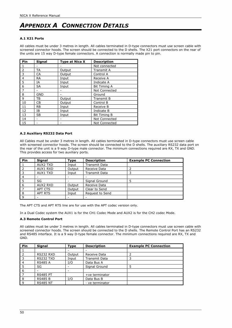
NICA X Reference Manual
50
APPENDIX A CONNECTION DETAILS
A.1 X21 Ports
All cables must be under 3 metres in length. All cables terminated in D-type connectors must use screen cable withscreened connector hoods. The screen should be connected to the D shells. The X21 port connectors on the rear ofthe units are 15 way D-type female connectors. A connection is normally made pin to pin.
Pin Signal Type at Nica X Description1 - - Not connected2 TA Output Transmit A3 CA Output Control A4 RA Input Receive A5 IA Input Indicate A6 SA Input Bit Timing A7 - - Not Connected8 GND - Ground9 TB Output Transmit B10 CB Output Control B11 RB Input Receive B12 IB Input Indicate B13 SB Input Bit Timing B14 - - Not Connected15 - - Not Connected
A.2 Auxiliary RS232 Data Port
All Cables must be under 3 metres in length. All cables terminated in D-type connectors must use screen cablewith screened connector hoods. The screen should be connected to the D shells. The auxiliary RS232 data port onthe rear of the unit is a 9 way D-type male connector. The minimum connections required are RX, TX and GND.This provides access for two auxiliary ports.
Pin Signal Type Description Example PC Connection1 AUX2 TXD Input Transmit Data2 AUX1 RXD Output Receive Data 23 AUX1 TXD Input Transmit Data 34 - - -5 SG - Signal Ground 56 AUX2 RXD Output Receive Data7 APT CTS Output Clear to Send8 APT RTS Input Request to Send9 - - -
The APT CTS and APT RTS line are for use with the APT codec version only.
In a Dual Codec system the AUX1 is for the CH1 Codec Mode and AUX2 is for the CH2 codec Mode.
A.3 Remote Control Port
All cables must be under 3 metres in length. All cables terminated in D-type connectors must use screen cable withscreened connector hoods. The screen should be connected to the D shells. The Remote Control Port has an RS232and RS485 interface. It is a 9 way D-type female connector. The minimum connections required are RX, TX andGND.
Pin Signal Type Description Example PC Connection1 - -2 RS232 RXD Output Receive Data 23 RS232 TXD Input Transmit Data 34 RS485 A I/O Data Bus A5 SG - Signal Ground 56 - -7 RS485 PT +ve terminator8 RS485 B I/O Data Bus B9 RS485 NT - ve terminator

NICA X Reference Manual
51
A.4 External Outputs
All cables must be under 3 metres in length. All cables terminated in D-type connectors must use screen cable withscreened connector hoods. The screen should be connected to the D shells. The Relay Output connector is a 15Way D-type female connector. These outputs are programmable.
Pin Relay Output1 +12V *2 +12V *3 Rly NO 24 Rly NO 45 Rly NO 66 Rly NO 87 COMMON8 GND9 +12V *10 Rly NO 111 Rly NO 312 Rly NO 513 Rly NO 714 COMMON15 GND
* Thermal Fuse protection internally at 1A
A.5 External Inputs
All cables must be under 3 metres in length. All cables terminated in D-type connectors must use screen cable withscreened connector hoods. The screen should be connected to the D shells. The Opto Input connector is a 15 WayD-type female connector. These inputs are programmable.
Pin Opto Input1 +12V *2 COMMON3 Opto IN 24 Opto IN 45 Opto IN 66 Opto IN 87 GND8 GND9 +12V *10 Opto IN 111 Opto IN 312 Opto IN 513 Opto IN 714 GND15 GND
* Thermal Fuse protection internally at 1A
A.6 Audio
All cables must be under 3 metres in length. All cables terminated in XLR connectors must use screen cable withscreened connector shells. The screen should be connected to the XLR shell.
Audio Input
The audio input connector is a 3 pin XLR female.
Pin Signal1 GND2 + Input3 - Input
Audio Output
The audio output connector is a 3 pin XLR male.
Pin Signal1 GND2 + Output3 - Output

NICA X Reference Manual
52
APPENDIX B REGULATORY STATEMENT
B.1 - CE Marking
The CE marking on this product denotes conformity to the European Directive 89/336/EC relating toElectromagnetic Compatibility and European Directive relating to The Low Voltage Directive.
B.2 - EMC Testing
Emissions Testing To EN55103-1Immunity Testing To EN55103-2
Below are notes which must be taken into account when using the NICA X. The NICA X product has been fullytested to the EMC standards as above in all Environments E1, E2, E3, E4, E5 at a NAMAS accredited test house.
Environment DescriptionE1 Residential E2 Commercial and light industrial (for example theatres)E3 Urban OutdoorsE4 controlled EMC environment (for example purpose built broadcasting and recording studios),
and the rural outdoorsE5 Heavy industrial and environments close to broadcast transmitters
For use in Environment E5 all cables connected to the unit must be below 1 metre in length.
B.3 - Electrostatic Discharge
For E5 the unit is tested to 8KV. This was shown to cause momentary loss of codec framing resulting inmomentary loss of audio, however the unit recovers normally. At 4KV tests there were no effects. (E1,E2,E3,E4)
RF Common Mode Immunity Induced on AC Mains cable.
For E5 only it is recommended that the AC mains be supplied through an RF Common Mode Filter.
B.4 - Radiated Immunity
For E5 only Radiated Immunity test levels showed that there could be an increase in the THD&N figures of theaudio at 10V/metre radiated field on the enclosure.
B.5 - Radiated Emissions
For all environments Radiated Emissions tests have shown that Ferrite clamps must be placed on cables connectedto the unit. These ferrite clamps are provided with the unit and must be fitted on any cable connected to the unit.The Large ones must be fitted to X21 cables, while the small ones must be fitted to audio cables. The ISDN cablewill be supplied with an integral ferrite which must be used.
B.6 - TA Module
This product uses an internal Teltrend Midas plus module
B.7 - Safety & Approval Notice
The MIDAS PLUS module is approved "Host Independent" for connection to ISDN Basic rate Publictelecommunication network interfaces compatible with CCITT 1.420. The approval number issued by the BritishApprovals Board for Telecommunications is AA605042.
It is designed to operate with a low voltage +5V d.c. ±5% (100mA) supply taken from the host power bus. Caremust be taken to ensure that the host is capable of supplying sufficient power for the module and all otherauxiliary apparatus drawing power from the host before you install the MIDAS PLUS module.
The interfaces with the host use Safe Extra Low voltages (SELV) only. SELV is a voltage that does not exceed42.4V peak a.c. or 60V d.c. You are advised to ensure that this module is installed only in host equipment whichhas a similar SELV interface.
In order to maintain the independent approval of the MIDAS PLUS module, it must be installed such that with theexception of the host bus connector, a clearance distance of 4.00mm and a creepage distance of 5.0 (8.0) mm ismaintained between the Midas plus module and all other parts of the host, including any expansion cards, whichuse or generate a voltage less than 250V (rms or dc); the creepage distance shown in brackets applies where thelocal environment within the host is subject to conductive pollution or dry non conductive pollution which couldbecome conductive due to condensation. If in doubt, please consult a qualified engineer before installation.

NICA X Reference Manual
53
APPENDIX C THE APT-X100 AUDIO DATA COMPRESSIONSYSTEM
C.1 - Introduction
Linear PCM coding of audio has now become virtually synonymous with ultimate sonic quality. Certainly, it hasraised both professional and public expectations of the performance of audible media. For most of its applications16 bit linear PCM produces fine results, but to take advantage of it in many situations is not without its problems.
In most of these, the overriding limiting factor is the enormous amount of bandwidth it occupies, with the generalresult that it is too costly or complex to be practically implemented. For example, using a linear 16 bit PCMsystem sampling at 32kHz, the basic binary bit rate will be 512kbit/s per channel.
The bandwidth problem of PCM is particularly acute in transmission environments, where the transmission costsare proportional to the channel capacity. As a result, a number of alternative music coding schemes have beendeveloped which require significantly lower operating bandwidth for these circuits. Such schemes, employing nearinstantaneous or delta modulation techniques, operate at bit rates of around 256-400kbit/s per channel, andinclude error protection overheads. However, for many potential low capacity digital audio applications, forexample ISDN, these levels of compression are still inadequate.
The excessive data rates of these existing music compression schemes have been due primarily to their adherenceto relatively simple digital companding techniques. These systems exploit little of the natural redundanciesassociated with the sound signals of interest, unlike their speech coding counterparts. The situation has remained,partly because of the higher sampling overheads involved, and until recently, the absence of high speed DigitalSignal Processing (DSP) hardware.
Sub-band ADPCM can be described as a "medium-complexity" scheme which appears particularly suited to highquality audio coding and which does exploit the considerable natural redundancies of audio. A high codingefficiency is ensured in this system as it not only incorporates the benefits of digital companding, but also takesadvantage of time and spectral redundancies by using linear prediction and sub-band coding.
This Chapter presents the concepts involved in sub-band ADPCM, explaining the nature of the signal redundancieswhich are exploited to provide a transparent 16 to 4 bit compression.
C.2 - Linear PCM Digital Audio Coding
The process by which audio is sampled and coded with a binary bit stream has the advantage of producing anaccurately repeatable quality. Noise and speed variations introduced by storage and transmission media can beeliminated, as can multiple generation degradation, and performance criteria such as frequency response anddistortion can be better controlled and therefore virtually guaranteed. However, the problems created by the verymuch higher frequencies required to code audio digitally, coupled with the necessity to maintain the originalintegrity of the code throughout any processing, inhibit and complicate its use in many applications.
The bit rate of PCM digital audio is defined by the sample frequency and the word length. The analogue signalmust be sampled at least twice per cycle in order to code the highest frequencies accurately. In practice it is alsonecessary to filter the high frequencies to avoid anti-aliasing distortion. By coding in this way an analoguewaveform is systematically dissected into many component parts, each one of which is accurately labelled so thatit can be exactly reconstructed again, regardless of whether or not the components are audible to the human ear.In many cases it will always be desirable to do this, however there are a great many instances where it is aconsiderable extravagance if not a positive disadvantage.
C.3 - Characteristics Of Audio
An audio signal can be defined as an analogue waveform containing frequency components to which the humanear responds. To be considered musical the signal must also be pleasing, and this is a factor on which some verylow bit rate coding schemes base greater emphasis than others, but all rely on it to some extent.
The characteristics of the response of the human ear are fundamental to the elimination of coding redundant data.Loud sounds mask quiet sounds of similar frequency, for example, and sensitivity is biased to low frequencysounds. Musical notes are made up of fundamental frequencies and a series of harmonics and, because of thetendency of the ear to lower frequencies, there are few signals that are considered musical with a fundamentalfrequency above about 4kHz. In fact music and audio signals in general exhibit a diversity of redundantcharacteristics of which very low bit rate coders are designed to take advantage.
The foremost requirement of hi-fi music coding is the maintenance of a high coding transparency. This impliesthat the quality, bandwidth and distortion/noise levels of both original and coded music should not be subjectivelydifferent. In theory a process relying on the inherent redundancy in music to maintain signal quality might notprove satisfactory for non-redundant signals. Fortunately, most signals of this class already incorporate specificperceptual redundancies to compensate for this (e.g. noisy signals which will invariably mask coding error). This isalso true for transient signals, which are exceptionally tolerant because of, amongst other things, temporalmasking (the response of the ear to short, sharp rises in level).
NICA X Reference Manual
54
C.4 - ADPCM Audio Coding
Adaptive Differential Pulse Code Modulation is a combination of two extreme quantising techniques: Linear PCM,described above, and Adaptive Differential coding. Differential coding reduces the bit rate of PCM by coding thedifference in level between audio samples, as opposed to the absolute level of each sample. Adaptive differentialcoding adapts the step size represented by each quantising interval depending on the nature of the audio signal.In this way rapid changes in level caused by high frequencies or transients can be accommodated, permitting anoverall reduction in bit rate.
C.5 - Sub-Band Coding
Split band techniques, such as sub-band coding, are used primarily to exploit spectral redundancies within theaudio spectrum. The mechanism of sub-band coding is to split the signal into a number of independent bands andto vary the accuracy of the QUANTISATION in each band according to the input signal energy. The effect of thisprocess is to allow the critical regions of the audio spectrum to be coded more accurately permitting greaterquantising energy to be concentrated on the high sensitivity, low frequencies. Or, perhaps more importantly, lessvaluable resources need be expended on coding the areas of the audio spectrum to which the ear is more tolerant.It also has the added advantage that the high energy regions are coded more accurately than PCM, giving a lowercoding noise floor. This improvement is commonly referred to as the sub-band gain.
Increasing the number of sub-bands improves the coder's ability to resolve the finer components of the signalspectrum, raising the overall sub-band gain. However, complexity, inter-band leakage, sub-band delay and anadequate energy classification procedure tend to offset the SNR advantage which may accompany an increasingnumber of bands.
An important subjective by-product of sub-band coding is the reduction in the perceived noise modulation overPCM. Since the audio signal is split into several frequency bands prior to quantisation, modulated quantisationnoise, developed at each quantiser, is constrained to that band and cannot interfere with signals in any otherband. As a result, noise masking by the modulating spectral component is much more effective due to thereduced noise bandwidth.
The apt-X100 system divides the audio spectrum into four sub-bands. The quantising levels in each band are thenadapted to the relative accuracy required to maximise perceived quality according to the spectral response of theear. The system automatically adjusts the band edges to changes in sample rates. It is important to note that thebottom band always covers the most critical area of the spectrum for any hi-fi music application, so that themusical fundamental frequencies are coded as accurately as possible.
Low bit rate Sub-band ADPCM coding alone, as so far described, cannot be relied upon to produce audibletransparency under all conditions. The real key to the superb performance of the apt-X100 system lies in twofurther uniquely implemented techniques.
C.6 - Backward Adaptive Quantisation
As explained earlier, adaption of the quantising step size according to the energy of the input signal enables theuse of lower bit rates. Controlling the adaption by analysis of previous samples makes it possible for the decoderto operate without being sent any gain information. This is achieved by comparing the accuracy of the currentsample with the previous one and applying correction in the form of an adaption multiplier from identical look-uptables in the encoder and decoder.
This process provides a near optimal range match over a wide dynamic range, and is particularly effective foradaptive quantisers with large numbers of levels.
Adaptive quantisation also maintains a constant signal to noise ratio throughout the entire dynamic range, unlikelinear PCM where the noise floor level is constant by nature. This exploits the masking properties of the humanauditory system.
C.7 - Linear Prediction
Audio signals of high spectral purity, such as tones, have a tendency to produce more audible noise modulationthan wide band signals, which have a greater masking effect. This can be controlled by the application of linearprediction prior to quantisation. Once again this involves analysing a small piece of history in order to attenuatepredictable signals.
The efficiency of this process actually rises dramatically with an increase in the signal periodicity or spectral purity.The combination of linear prediction and sub-band coding thus avoids the need to resolve the spectrum in order topreferentially code the resonant components. By keeping within four sub-bands, the stationary characteristics ofthe sub-band signals are such that backward adaptive prediction has been found to provide an almost optimalperformance. This is particularly true for sinusoidal type signals whose predictability is largely unaffected by sub-band decimation. However, it is also proven that substantial prediction gains exist for the vast majority of musicsounds, and the validity of linear prediction for speech coding has been well documented.
The overall effect of linear prediction, therefore, is to attenuate predictable signals, of which the most subjectively

NICA X Reference Manual
55
critical are highly resonant spectra. There is a potential drawback in the presence of noise-like signals as, undersuch conditions, the prediction process is incapable of providing any coding gain. Fortunately, the significance ofthis effect is eclipsed by the inherent noise masking which accompanies these signals.
C.8 - apt-X100 Sub-Band ADPCM
Sub-band ADPCM has been shown to be a very efficient solution to the problem of high quality audio compression.The diversity of redundancy removal processes involved not only reduce its sensitivity to uncharacteristic signals,but collectively take advantage of the best properties of each. This means that non-musical or discordant soundsare treated as any other signal and will be faithfully reproduced.
The code is structured as a series of 16 bit words. The scheme has been referred to as 4 bit digital audio. Moreaccurately it is 4 bits per sample, as one code word is generated for every four 16 bit linear PCM words input. Thisscheme uses a 4 band QMF (Quadrature Mirror Filter) tree structure where each band incorporates a backwardadaptive quantiser and predictive block.
By allowing all parameter adaptations within the encoder and encoder blocks to follow in a backward mode, nospecific side information is transmitted between them. The effect of this is to improve the immunity of the systemto transmission errors and to reduce the coding delay across the encoder-decoder process.
C.9 - Inherent Properties
REAL-TIME OPERATION. The processing power of today's high speed digital signal processing technology hasmade it possible to code and decode audio in real-time.
LOW, CONSTANT CODING DELAY. By operating in the time domain to analyse the audio signal, the amount ofbackward information required to optimise the predictors is relatively small, giving the advantage of a minimalcoding delay. The calculations are made accurately over a fixed 122 samples, making the total constant codexdelay 3.8mS at a sample rate of 32kHz - the time it takes audio to travel approximately 1.25 metres, or a littleover 4 feet. The effects of this delay are inaudible for live off-air foldback and compensation is unnecessary forsynchronisation with picture.
AUTOMATIC RESOLUTION TO ANY SAMPLE FREQUENCY UP TO 50KHZ. Sub-band coding is able to be resolved toany input sample frequency. In fact, the upper band limit is caused by the speed of the processing technologyused. This means that apt -X100 can be implemented without modification into systems needing the widebandwidth performance of 48kHz sampling, or to squeeze high quality speech into 64kbit/s using a 16kHz samplerate.
HIGH IMMUNITY TO BIT ERRORS. Linear PCM, by its nature, is a very fragile medium. As each word ofinformation is describing an analogue level, any corruption of the data can have disastrous results, causing a rapidbreakdown in the sonic performance. The effects of errors range from nasty spiky clicks to white noise at fullmodulation. The information contained in the apt-X100 code describe a temporal analysis of the waveform andtherefore the effects of corrupting the data are far less severe, making the process several orders of magnitudemore robust. So resistant, in fact, that it has so far not been deemed necessary to provide any form of errorprotection under normal operating conditions.

NICA X Reference Manual
56
APPENDIX D SPECIFICATIONS
Specification DescriptionMaximum Input/Output Level 12dBu APTX /18dBu MPEGInput Impedance <10kOhmsOutput Impedance >60 OhmsInputs and Outputs BalancedHeadphone Monitor , Level Indicator Input / output - selectableSilence Detector Variable - InputMic Input Optional - 60dBu levelFrequency Response 20Hz - 15kHz depending on coding modeCoding Standard apt-X100, MPEG L2, G.722Inverse Multiplexing Standard apt MUCAS 2 x 64kBit/sSample rate 16,24,32,48KHzBit Error Immunity 1 x 10⁻⁴
Auxiliary Data RS232 1200 - 9600 baudLogic Inputs 8 Opto InputsLogic Outputs 8 Relay outputsAlarm Output Uses Relay OutputsBackup Switchover Loss of Framing
Silence DetectorLogic Input
Backup Logic User SelectableAudio Routing Relay Option BoardISDN TA Module International CompatibilityDigital Interface 2 x X.21 DTESize NICA X-1 1U 19" 300mm deepSize NICA X-2 2U 19" 300mm deepPower 90 - 250V ac/dcEMC Approval EN 55103-1
EN55103-2LVD EN 60950
23/8/00 Page 82 Relay output changed to Opto Input in table heading13/2/01 Added in State Machine 2 operation
Related Documents