May 2013 371133T GETTING STARTED GUIDE NI High-Speed Digitizers This document contains English and Japanese language instructions. This document explains how to install, configure, and test NI high-speed digitizers and accessories, and how to begin programming them using the NI-SCOPE instrument driver software. This document applies to the following digitizers and accessories: NI 5105, NI 5114, NI 5122, NI 5124, NI 5132, NI 5133, NI 5142, NI 5152, NI 5153, NI 5154, NI 5160, NI 5162, NI 5185, NI 5186, NI 5620, NI 5621, NI 5622, NI 5900, and NI 5922. For more information on features and programming, refer to the NI High-Speed Digitizers Help. For device specifications, refer to the specifications document included with your device. To access these documents, select Start»All Programs»National Instruments»NI-SCOPE» Documentation. (Windows 8) Click NI Launcher and select NI-SCOPE»Documentation in the window that appears. For the most current versions of documentation, visit ni.com/manuals. For the latest version of NI-SCOPE, visit ni.com/downloads. Contents Safety and Electromagnetic Compatibility ............................................................................... 2 1. Verifying System Requirements ........................................................................................... 3 2. Unpacking............................................................................................................................. 3 3. Verifying the Kit Contents ................................................................................................... 3 Other Required Items........................................................................................................ 4 4. Installing the Software .......................................................................................................... 4 5. Installing the Hardware ........................................................................................................ 5 PXI/PXI Express Modules................................................................................................ 5 NI PXIe-5185/5186 Modules ........................................................................................... 6 NI PXIe-5185/5186 Startup Behavior ...................................................................... 8 PCI Devices ...................................................................................................................... 8 USB Devices..................................................................................................................... 9 USB Cable Strain Relief ........................................................................................... 10 Mounting the USB-5132/5133 ......................................................................................... 11 Desktop Use.............................................................................................................. 11 DIN Rail Mounting................................................................................................... 11 Panel Mounting......................................................................................................... 12

Welcome message from author
This document is posted to help you gain knowledge. Please leave a comment to let me know what you think about it! Share it to your friends and learn new things together.
Transcript

May 2013371133T
GETTING STARTED GUIDE
NI High-Speed DigitizersThis document contains English and Japanese language instructions.
This document explains how to install, configure, and test NI high-speed digitizers and accessories, and how to begin programming them using the NI-SCOPE instrument driver software. This document applies to the following digitizers and accessories: NI 5105, NI 5114, NI 5122, NI 5124, NI 5132, NI 5133, NI 5142, NI 5152, NI 5153, NI 5154, NI 5160, NI 5162, NI 5185, NI 5186, NI 5620, NI 5621, NI 5622, NI 5900, and NI 5922.
For more information on features and programming, refer to the NI High-Speed Digitizers Help. For device specifications, refer to the specifications document included with your device. To access these documents, select Start»All Programs»National Instruments»NI-SCOPE»Documentation. (Windows 8) Click NI Launcher and select NI-SCOPE»Documentation in the window that appears.
For the most current versions of documentation, visit ni.com/manuals. For the latest version of NI-SCOPE, visit ni.com/downloads.
ContentsSafety and Electromagnetic Compatibility............................................................................... 21. Verifying System Requirements........................................................................................... 32. Unpacking............................................................................................................................. 33. Verifying the Kit Contents ................................................................................................... 3
Other Required Items........................................................................................................ 44. Installing the Software.......................................................................................................... 45. Installing the Hardware ........................................................................................................ 5
PXI/PXI Express Modules................................................................................................ 5NI PXIe-5185/5186 Modules ........................................................................................... 6
NI PXIe-5185/5186 Startup Behavior ...................................................................... 8PCI Devices ...................................................................................................................... 8USB Devices..................................................................................................................... 9
USB Cable Strain Relief........................................................................................... 10Mounting the USB-5132/5133 ......................................................................................... 11
Desktop Use.............................................................................................................. 11DIN Rail Mounting................................................................................................... 11Panel Mounting......................................................................................................... 12

2 | ni.com | NI High-Speed Digitizers Getting Started Guide
Windows Device Recognition ..........................................................................................136. Configuring and Testing in MAX.........................................................................................137. Programming the Device ......................................................................................................15
Acquiring Data Interactively ............................................................................................15Acquiring Data Programmatically ....................................................................................15NI-SCOPE Examples........................................................................................................16
8. Making Your First Measurement..........................................................................................16Appendix A: Front Panels for SMC-Based Devices and USB Devices ...................................17
NI 5105 Front Panels ........................................................................................................17NI 5114 Front Panels ........................................................................................................18NI 5122/5124/5142/5922 Front Panels.............................................................................19NI 5132/5133 Front Panels ...............................................................................................21NI 5152/5153/5154 Front Panels ......................................................................................22NI 5160/5162 Front Panels ...............................................................................................23
NI 5160/5162 (2 CH)................................................................................................23NI 5160/5162 (4 CH)................................................................................................24
NI 5185/5186 Front Panels ...............................................................................................25Previous NI 5185/5186 Modules ..............................................................................26
NI 5622 Front Panels ........................................................................................................27Appendix B: Front Panels for Traditional NI-DAQ (Legacy) Devices....................................28
NI 5620/5621 Front Panels ...............................................................................................28Appendix C: Accessory Front Panels .......................................................................................29
NI 5900 Front Panel..........................................................................................................29Appendix D: Troubleshooting ..................................................................................................31
Front Panel ACCESS LED on PXI/PXI Express Module is Off when PXI/PXI Express Chassis is On .................................................................................................................31
Back Panel LED on USB Module is Off when Device is Plugged In ..............................31Device Does Not Appear in MAX....................................................................................32Device Failed the Self-Test...............................................................................................32Thermal Shutdown Error ..................................................................................................32Performance Issues Using MXI Connections ...................................................................32Setting Up SMC-Based Devices for Synchronization ......................................................33
Appendix E: Where to Go for Support .....................................................................................34
Safety and Electromagnetic CompatibilityRefer to the Read Me First: Safety and Electromagnetic Compatibility document for important safety and electromagnetic compatibility information. To obtain a copy of this document online, visit ni.com/manuals, and search for the document title.
For additional and electromagnetic compatibility information, including any product-specific installation or configuration requirements necessary to achieve the specified level of electromagnetic compatibility performance, refer to the individual product specifications.
NI High-Speed Digitizers Getting Started Guide | © National Instruments | 3
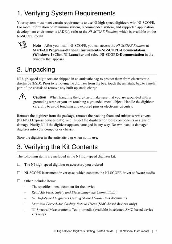
1. Verifying System RequirementsYour system must meet certain requirements to use NI high-speed digitizers with NI-SCOPE. For more information on minimum system, recommended system, and supported application development environments (ADEs), refer to the NI-SCOPE Readme, which is available on the NI-SCOPE media.
Note After you install NI-SCOPE, you can access the NI-SCOPE Readme at Start»All Programs»National Instruments»NI-SCOPE»Documentation. (Windows 8) Click NI Launcher and select NI-SCOPE»Documentation in the window that appears.
2. UnpackingNI high-speed digitizers are shipped in an antistatic bag to protect them from electrostatic discharge (ESD). Prior to removing the digitizer from the bag, touch the antistatic bag to a metal part of the chassis to remove any built up static charge.
Caution When handling the digitizer, make sure that you are grounded with a grounding strap or you are touching a grounded metal object. Handle the digitizer carefully to avoid touching any exposed pins or electronic circuitry.
Remove the digitizer from the package, remove the packing foam and rubber screw covers (PXI/PXI Express devices only), and inspect the digitizer for loose components or signs of damage. Notify NI if the digitizer appears damaged in any way. Do not install a damaged digitizer into your computer or chassis.
Store the digitizer in the antistatic bag when not in use.
3. Verifying the Kit ContentsThe following items are included in the NI high-speed digitizer kit:
The NI high-speed digitizer or accessory you ordered
NI-SCOPE instrument driver case, which contains the NI-SCOPE driver software media
Other included items:
– The specifications document for the device
– Read Me First: Safety and Electromagnetic Compatibility
– NI High-Speed Digitizers Getting Started Guide (this document)
– Maintain Forced-Air Cooling Note to Users (SMC-based devices only)
– NI Spectral Measurements Toolkit media (available in selected SMC-based device kits only)
4 | ni.com | NI High-Speed Digitizers Getting Started Guide
– USB cable (USB devices only)
– NI SignalExpress media (USB devices only)
Note SMC-based devices are based on the National Instruments Synchronization and Memory Core architecture. For more information, refer to the NI High-Speed Digitizers Help.
Other Required ItemsIn addition to the items contained in the kit, you need the following items:
1/8 in. flat-head screwdriver
One of the following configurations:
– (PXI Devices) A PXI chassis, a PXI/SCXI combination chassis, or a PXI/CompactPCI chassis with a controller and the chassis documentation
– (PXI Express Devices) A PXI Express chassis with a controller and the chassis documentation
– (USB Devices) A desktop or laptop computer and its documentation
– (PCI Devices) A desktop computer and its documentation
Note If your application uses NI-TClk synchronization for PCI Devices, you must use a RTSI cable to connect the PCI DeviceS. For more information, refer to NI High-Speed Digitizers Help»Programming»Reference»NI-TClk Synchronization Help.
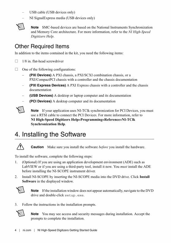
4. Installing the Software
Caution Make sure you install the software before you install the hardware.
To install the software, complete the following steps:
1. (Optional) If you are using an application development environment (ADE) such as LabVIEW or if you are using a third-party tool, install it now. You must install the ADE before installing the NI-SCOPE instrument driver.
2. Install NI-SCOPE by inserting the NI-SCOPE media into the DVD drive. Click Install Software in the displayed window.
Note If the installation window does not appear automatically, navigate to the DVD drive and double-click setup.exe.
3. Follow the instructions in the installation prompts.
Note You may see access and security messages during installation. Accept the prompts to complete the installation.

NI High-Speed Digitizers Getting Started Guide | © National Instruments | 5
4. When the installer completes, a dialog box prompts you to Restart, Shut Down, or Restart Later. Select Restart.
5. If you are using a system running the LabVIEW Real-Time Module, download NI-SCOPE to the target using Measurement &Automation Explorer (MAX). For more information, refer to the MAX Remote Systems Help by selecting Help»Help Topics»Remote Systems in MAX.
5. Installing the HardwareThis section describes how to install hardware for PXI/PXI Express, PCI, and USB platforms.
Note You must install the software before you install the hardware.
To prevent damage to the device caused by ESD or contamination, handle the device using the edges or the metal bracket. For more information, refer to the Read Me First: Safety and Electromagnetic Compatibility document.
Caution Unless you are using a USB device, you must power off and unplug your PC or chassis before installing the hardware.
PXI/PXI Express ModulesNI PXI and PXI Express modules are sensitive instruments that should be handled carefully. Do not expose the module to temperatures or humidity beyond the rated maximums. Keep the module free of dust by cleaning with compressed air only. Do not clean the device with any solvents or liquids.
You can install PXI modules in any PXI slot marked with a peripheral slot compatibility glyph (a circle containing the slot number).
You can install PXI Express modules in a PXI Express slot of the chassis. Refer to the chassis documentation for information about the markings that denote PXI Express slots.
To install a PXI/PXI Express module, complete the following steps:
1. Power off and unplug the PXI/PXI Express chassis before installing the module.
2. If the PXI/PXI Express chassis has multiple fan speed settings, make sure that the fans are set to high.
3. Position the PXI/PXI Express chassis so that inlet and outlet vents are not obstructed. For more information, refer to the chassis documentation.
4. Make sure that the ejector handle of the module is in the unlatched (downward) position.
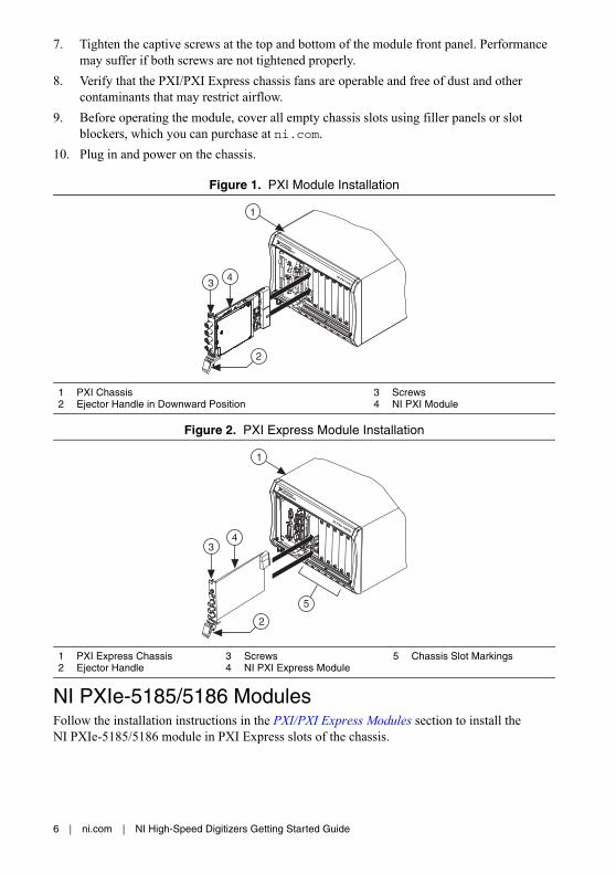
5. Holding the module by the ejector handle, slide it into an empty slot as shown in Figure 1 (PXI modules) or Figure 2 (PXI Express modules), or Figure 3 (NI PXIe-5185/5186 modules). Make sure that the base engages with the guides in the chassis.
6. Slide the module completely into the chassis and latch it by pulling up on the ejector handle.
6 | ni.com | NI High-Speed Digitizers Getting Started Guide
7. Tighten the captive screws at the top and bottom of the module front panel. Performance may suffer if both screws are not tightened properly.
8. Verify that the PXI/PXI Express chassis fans are operable and free of dust and other contaminants that may restrict airflow.
9. Before operating the module, cover all empty chassis slots using filler panels or slot blockers, which you can purchase at ni.com.
10. Plug in and power on the chassis.
Figure 1. PXI Module Installation
Figure 2. PXI Express Module Installation
NI PXIe-5185/5186 ModulesFollow the installation instructions in the PXI/PXI Express Modules section to install the NI PXIe-5185/5186 module in PXI Express slots of the chassis.
1 PXI Chassis2 Ejector Handle in Downward Position
3 Screws4 NI PXI Module
1 PXI Express Chassis2 Ejector Handle
3 Screws4 NI PXI Express Module
5 Chassis Slot Markings
3
2
4 NI PXI-1042
1
34
2
1
NI PXIe-1062Q
5
NI High-Speed Digitizers Getting Started Guide | © National Instruments | 7
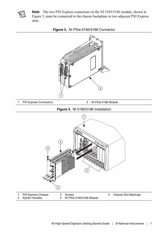
Note The two PXI Express connectors on the NI 5185/5186 module, shown in Figure 3, must be connected to the chassis backplane in two adjacent PXI Express slots.
Figure 3. NI PXIe-5185/5186 Connector
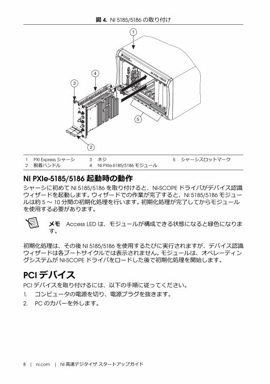
Figure 4. NI 5185/5186 Installation
1 PXI Express Connectors 2 NI PXIe-5186 Module
1 PXI Express Chassis2 Ejector Handles
3 Screws4 NI PXIe-5185/5186 Module
5 Chassis Slot Markings
1
2
NI PXIe-1062Q3
4
5
2
1
8 | ni.com | NI High-Speed Digitizers Getting Started Guide
NI PXIe-5185/5186 Startup BehaviorThe first time you install the NI 5185/5186 in the chassis, the NI-SCOPE driver launches a device recognition wizard. After the wizard completes, the NI 5185/5186 module goes through an initialization procedure that lasts approximately 5 to 10 minutes. You must wait until the initialization procedure completes before using the module.
Note The Access LED turns green when the module is ready to be configured.
The initialization procedure will occur on each subsequent use of the NI 5185/5186, although the device recognition wizard is not repeated on each subsequent boot cycle. The module will begin the initialization procedure after the NI-SCOPE driver has been loaded by the operating system.
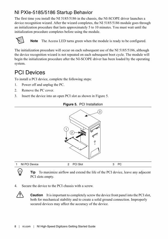
PCI DevicesTo install a PCI device, complete the following steps:
1. Power off and unplug the PC.
2. Remove the PC cover.
3. Insert the device into an open PCI slot as shown in Figure 5.
Figure 5. PCI Installation
Tip To maximize airflow and extend the life of the PCI device, leave any adjacent PCI slots empty.
4. Secure the device to the PCI chassis with a screw.
Caution It is important to completely screw the device front panel into the PCI slot, both for mechanical stability and to create a solid ground connection. Improperly secured devices may affect the accuracy of the device.
1 NI PCI Device 2 PCI Slot 3 PC
12
3

NI High-Speed Digitizers Getting Started Guide | © National Instruments | 9
(SMC-Based Devices) Some computer manufacturers use a securing lever made of plastic to secure PCI devices; such a lever is unacceptable and must be removed. Use the screw provided in the kit to screw down the digitizer. Otherwise, you must use a different computer chassis.
5. Replace the PC cover.
6. Plug in and power on the PC.
7. (SMC-Based Devices) Verify that spread-spectrum clocking is enabled in the PC BIOS. For information about how to verify this setting, refer to the PC user documentation.
Note For SMC-based devices, spread-spectrum clocking varies the clock signal to spread the timing clock signal over a small frequency range. Disabling spread-spectrum clocking may affect the accuracy of device specifications.
USB DevicesTo install a USB device, connect the USB cable to the PC and the digitizer, as shown in Figure 6.
Figure 6. USB Installation
1 Laptop Computer 2 NI USB High-Speed Digitizer 3 USB Cable
2
1
3
10 | ni.com | NI High-Speed Digitizers Getting Started Guide
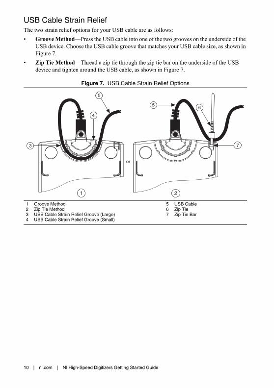
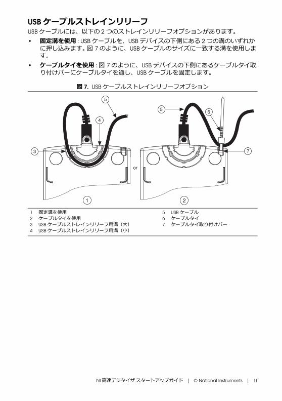
USB Cable Strain ReliefThe two strain relief options for your USB cable are as follows:
• Groove Method—Press the USB cable into one of the two grooves on the underside of the USB device. Choose the USB cable groove that matches your USB cable size, as shown in Figure 7.
• Zip Tie Method—Thread a zip tie through the zip tie bar on the underside of the USB device and tighten around the USB cable, as shown in Figure 7.
Figure 7. USB Cable Strain Relief Options
1 Groove Method2 Zip Tie Method3 USB Cable Strain Relief Groove (Large)4 USB Cable Strain Relief Groove (Small)
5 USB Cable6 Zip Tie7 Zip Tie Bar
4
3
5
5
7
6
or
1 2

NI High-Speed Digitizers Getting Started Guide | © National Instruments | 11
Mounting the USB-5132/5133You can use the NI USB-5132/5133 on a desktop or mount it to a standard DIN rail or a panel.
Desktop UseThe NI USB-5132/5133 has plastic guides on the underside that allow it to be stacked on top of other NI USB-5132/5133 devices.
For secure desktop use, you can adhere the supplied rubber non-skid feet to the underside of the device, as shown in Figure 8.
Note Do not apply the rubber feet if you are panel mounting the NI USB-5132/5133 or stacking it on top of another NI USB-5132/5133 device.
Figure 8. Applying Rubber Feet to the USB-513x
DIN Rail MountingThe DIN rail mounting kit (part number 779689-01, not included in your USB-513x kit) is an accessory you can use to mount the USB-513x family of products to a standard DIN rail.
Note Apply strain relief, as described in the USB Cable Strain Relief section, before mounting the USB-513x to a DIN rail.
1 NI USB High-Speed Digitizer 2 Plastic Guides 3 Rubber Feet
3
2
2
1
12 | ni.com | NI High-Speed Digitizers Getting Started Guide
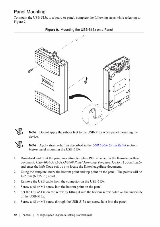
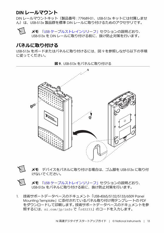
Panel MountingTo mount the USB-513x to a board or panel, complete the following steps while referring to Figure 9.
Figure 9. Mounting the USB-513x on a Panel
Note Do not apply the rubber feet to the USB-513x when panel mounting the device.
Note Apply strain relief, as described in the USB Cable Strain Relief section, before panel mounting the USB-513x.
1. Download and print the panel mounting template PDF attached in the KnowledgeBase document, USB-4065/5132/5133/6509 Panel Mounting Template. Go to ni.com/info and enter the Info Code rd3233 to locate the KnowledgeBase document.
2. Using the template, mark the bottom point and top point on the panel. The points will be 162 mm (6.375 in.) apart.
3. Remove the USB cable from the connector on the USB-513x.
4. Screw a #8 or M4 screw into the bottom point on the panel.
5. Set the USB-513x on the screw by fitting it into the bottom screw notch on the underside of the USB-513x.
6. Screw a #8 or M4 screw through the USB-513x top screw hole into the panel.

NI High-Speed Digitizers Getting Started Guide | © National Instruments | 13
Windows Device RecognitionWindows recognizes any newly installed device the first time the computer reboots after hardware is installed. On some Windows systems, the Found New Hardware wizard opens with a dialog box for every NI device installed. Install the software automatically (Recommended) is selected by default. Click Next or Yes to install the software for each device.
Note (USB devices) When you first install an NI USB-5132/5133, Windows will recognize a new device. Click Next on any dialog boxes that appear to complete the installation.
After Windows recognizes the newly installed device, a dialog box prompts you to select from the following options, which may vary depending on the devices and software installed on your system:
• Begin a Measurement with This Device Using NI SignalExpress opens SignalExpress.
• Use This Device Interactively launches the NI-SCOPE Soft Front Panel (SFP).
• Begin an Application with This Device launches LabVIEW.
• Configure and Test This Device opens MAX to your device so you can configure settings.
• Take No Action leaves your device in the system but does not launch an application.
6. Configuring and Testing in MAX
Note (NI 5185/5186) After you install the NI 5185/5186 in the chassis, the Access LED will remain amber while the NI 5185/5186 is configuring device firmware and initializing the device. During this time, the device is not available for user access. When the Access LED changes to solid green, you can begin configuring the device in MAX.

14 | ni.com | NI High-Speed Digitizers Getting Started Guide
1. Launch MAX by double-clicking the Measurement & Automation icon on the desktop. Figure 10 shows the MAX Configuration Pane.
Figure 10. MAX Configuration Pane
2. Expand Devices and Interfaces to see the list of installed devices. If you are using a digitizer with the LabVIEW Real-Time Module, expand Remote Systems. Find your target IP address or name, expand it, and then expand Devices and Interfaces.
3. If your device is not listed, press <F5> to refresh. If the device is still not listed, repeat the steps in section 5. Installing the Hardware. For more information about using MAX, refer to the help files available within MAX.
Note Windows 8 (64-bit), Windows 7 (64-bit) and Windows Vista (64-bit) do not support Traditional NI-DAQ (Legacy) devices. Refer to the NI-SCOPE Readme to determine which operating system is compatible with your digitizer.
4. Record the device number or device name assigned by MAX. You need this identifier when you program your device.
5. Perform a self-test on the device to verify installation.
• Right-click the device and select Self-Test.
• (Traditional NI-DAQ [Legacy] Devices) Right-click the device, select Configure, and click Test Resources.
A dialog box indicates whether the device has passed the test.
NI High-Speed Digitizers Getting Started Guide | © National Instruments | 15
Note If the device does not pass the self-test, repeat the instructions in section 5. Installing the Hardware. If the device still does not pass, visit NI Technical Support at ni.com/support.
6. Run the test panels on the device to verify the signal.
a. Connect a signal to the digitizer and select the appropriate device parameters for this signal such as range, input limits, sample rate, and sample mode.
b. Access the test panel.
• Right-click the device and select Test Panels.
• (Traditional NI-DAQ [Legacy] Devices) Click Run Test Panels in the Configure window.
Note All NI digitizers have self-calibration capabilities. You can access this feature programmatically with NI-SCOPE and your ADE, or you can use either the NI-SCOPE Soft Front Panel (SFP) or MAX. Traditional NI-DAQ (Legacy) devices cannot be self-calibrated using MAX.
7. Exit MAX when you have finished configuring and testing the digitizer.
7. Programming the DeviceYou can acquire data interactively using the NI-SCOPE Soft Front Panel or programmatically using the NI-SCOPE instrument driver in your application. You can also run the NI-SCOPE examples to demonstrate the functionality of the digitizer.
Acquiring Data InteractivelyLaunch the NI-SCOPE SFP from Start»All Programs»National Instruments»NI-SCOPE»SCOPE Soft Front Panel. (Windows 8) Click NI Launcher and select NI-SCOPE»SCOPE Soft Front Panel in the window that appears. The NI-SCOPE SFP provides context-sensitive help for its controls.
Acquiring Data ProgrammaticallyYou can use NI-SCOPE to begin programming the digitizer in your ADE. For detailed instructions about how to acquire data in a specific ADE, refer to the Getting Started with NI-SCOPE section of the NI High-Speed Digitizers Help located at Start»All Programs»National Instruments»NI-SCOPE»Documentation»NI High-Speed Digitizers Help. (Windows 8) Click NI Launcher and select NI-SCOPE»Documentation»NI High-Speed Digitizers Help in the window that appears.
Tip You can modify an NI-SCOPE C example to create an application with Microsoft Visual C/C++, and all required include and library files are automatically added to the project. Refer to the Creating an Application with Microsoft Visual C and C++ topic of the NI High-Speed Digitizers Help if you prefer to manually add all required include and library files to the project.

16 | ni.com | NI High-Speed Digitizers Getting Started Guide
NI-SCOPE ExamplesExamples demonstrate the functionality of the device, serving as programming models and building blocks for your own applications. The NI Example Finder is a utility available for some software applications that organizes examples into categories and allows you to easily browse and search installed examples. You can see descriptions and compatible hardware models for each example or see all the examples compatible with one particular hardware model.
To locate examples, refer to the following table.
8. Making Your First MeasurementTo begin making measurements with an NI high-speed digitizer, complete the following steps:
1. Launch your ADE.
2. Navigate to Start»All Programs»National Instruments»NI-SCOPE»Examples and open one of the examples. (Windows 8) Click NI Launcher and select NI-SCOPE»Examples. If you are not sure which example to run, begin with the Getting Started example.
3. Enter the correct string into the resource name control or parameter. This string varies if the digitizer is a Traditional NI-DAQ device. For more information about device names, refer to any of the following resources.
• Section 6. Configuring and Testing in MAX of this document
• NI High-Speed Digitizers Help»Programming»Reference»NI-SCOPE LabVIEW Reference»VIs»niScope Initialize
• NI High-Speed Digitizers Help»Programming»Reference»NI-SCOPE Function Reference Help»Functions»niScope_init
4. Adjust the parameters, if necessary, to capture the input signal that you want to acquire.
Software Application Locating Examples
LabVIEW or LabWindows™/CVI™
Locate examples with the NI Example Finder. Within LabVIEW or LabWindows/CVI, select Help»Find Examples and navigate to Hardware Input and Output»Modular Instruments.
ANSI C or Visual Basic Locate examples in the <NIDocDir>\NI-SCOPE\examples directory, where <NIDocDir> is one of the following directories:
• (Windows 2000/XP) Documents and Settings\All Users\Shared Documents\National Instruments
• (Windows Vista) Users\Public\Documents\National Instruments
• (Windows 7/8) Users\Public\Public Documents\National Instruments
NI High-Speed Digitizers Getting Started Guide | © National Instruments | 17
5. Connect the signal that you want to acquire to one of the input channels of the digitizer. For information about the appropriate connections, refer to Appendix A: Front Panels for SMC-Based Devices and USB Devices or to Appendix B: Front Panels for Traditional NI-DAQ (Legacy) Devices.
6. Run the example program.
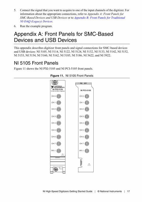
Appendix A: Front Panels for SMC-Based Devices and USB DevicesThis appendix describes digitizer front panels and signal connections for SMC-based devices and USB devices: NI 5105, NI 5114, NI 5122, NI 5124, NI 5132, NI 5133, NI 5142, NI 5152, NI 5153, NI 5154, NI 5160, NI 5162, NI 5185, NI 5186, NI 5622, and NI 5922.
NI 5105 Front PanelsFigure 11 shows the NI PXI-5105 and NI PCI-5105 front panels.
Figure 11. NI 5105 Front Panels
NI PXI-510512-Bit 60 MS/s Digitizer
PFI 1
CH 0
CH 1
CH 2
CH 3
CH 4
CH 5
CH 6
CH 7
PFI 1
CH 0
CH 1
CH 2
CH 3
CH 4
CH 5
CH 6
CH 7
NI PCI-5105
18 | ni.com | NI High-Speed Digitizers Getting Started Guide
Table 1 describes the signal connections for the NI 5105.
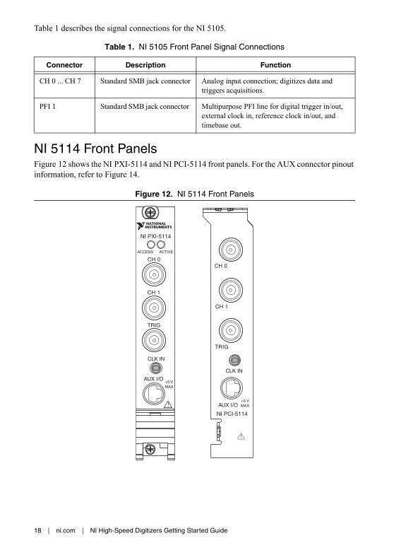
NI 5114 Front PanelsFigure 12 shows the NI PXI-5114 and NI PCI-5114 front panels. For the AUX connector pinout information, refer to Figure 14.
Figure 12. NI 5114 Front Panels
Table 1. NI 5105 Front Panel Signal Connections
Connector Description Function
CH 0 ... CH 7 Standard SMB jack connector Analog input connection; digitizes data and triggers acquisitions.
PFI 1 Standard SMB jack connector Multipurpose PFI line for digital trigger in/out, external clock in, reference clock in/out, and timebase out.
TRIG
CH 0
CH 1
AUX I/O+5 VMAX
CLK IN
NI PCI-5114
CH 0
CH 1
CLK IN
AUX I/O
TRIG
NI PXI-5114
NI High-Speed Digitizers Getting Started Guide | © National Instruments | 19
Table 2 describes the signal connections for the NI 5114.
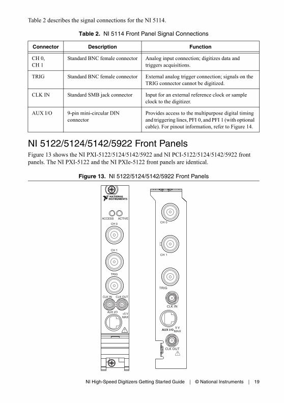
NI 5122/5124/5142/5922 Front PanelsFigure 13 shows the NI PXI-5122/5124/5142/5922 and NI PCI-5122/5124/5142/5922 front panels. The NI PXI-5122 and the NI PXIe-5122 front panels are identical.
Figure 13. NI 5122/5124/5142/5922 Front Panels
Table 2. NI 5114 Front Panel Signal Connections
Connector Description Function
CH 0,CH 1
Standard BNC female connector Analog input connection; digitizes data and triggers acquisitions.
TRIG Standard BNC female connector External analog trigger connection; signals on the TRIG connector cannot be digitized.
CLK IN Standard SMB jack connector Input for an external reference clock or sample clock to the digitizer.
AUX I/O 9-pin mini-circular DIN connector
Provides access to the multipurpose digital timing and triggering lines, PFI 0, and PFI 1 (with optional cable). For pinout information, refer to Figure 14.

20 | ni.com | NI High-Speed Digitizers Getting Started Guide
Table 3 describes the signal connections for the NI 5122/5124/5142/5922.
Figure 14 shows the pin assignments for the 9-pin DIN connector.
Figure 14. 9-Pin DIN Connector Pin Assignments for NI 5114/5122/5124/5142/5922
Table 3. NI 5122/5124/5142/5922 Front Panel Signal Connections
Connector Description Function
CH 0, CH 1
Standard BNC female connector Analog input connection; digitizes data and triggers acquisitions.
TRIG Standard BNC female connector External analog trigger connection; signals on the TRIG connector cannot be digitized.
CLK IN Standard SMB jack connector (NI 5122/5124/5142) Input for an external reference clock or sample clock to the digitizer.
(NI 5922) Input for an external reference clock to the digitizer.
CLK OUT Standard SMB jack connector (NI 5122/5124/5142) Output for the reference clock or sample clock.
(NI 5922) Output for the reference clock.
AUX I/O 9-pin mini-circular DIN connector
Provides access to the multipurpose digital timing and triggering lines, PFI 0, and PFI 1 (with optional cable). For pinout information, refer to Figure 14.
1 +5 V (Fused)2 GND3 Reserved
4 Reserved5 Reserved6 PFI 1
7 Reserved8 Reserved9 PFI 0
4
3
5
6
7
8
9
1
2

NI High-Speed Digitizers Getting Started Guide | © National Instruments | 21
NI 5132/5133 Front PanelsFigure 15 shows the NI USB-5132 and NI USB-5133 front panels.
Figure 15. NI 5132/5133 Front Panels
Figure 16 shows the NI 5132/5133 back panel.
Figure 16. NI 5132/5133 Back Panel
Table 4 describes the signal connections for the NI 5132/5133.
1 Recessed USB port 2 LED 3 Ground
Table 4. NI 5132/5133 Front Panel Signal Connections
Connector Description Function
CH 0, CH 1
Standard BNC female connector Analog input connection; digitizes data and triggers acquisitions.
PFI 1 Standard BNC female connector Multipurpose PFI line for sample clock in, digital trigger in/out, and probe compensation.
CH 0
NI USB-5133
CH 1 PFI 1
8-bit, 100 MS/s Digitizer
CH 0
NI USB-5132
CH 1 PFI 1
8-bit, 50 MS/s Digitizer
1
2
3

22 | ni.com | NI High-Speed Digitizers Getting Started Guide
NI 5152/5153/5154 Front PanelsFigure 17 shows the NI PXI-5152/5153/5154 and NI PCI-5152/5153/5154 front panels.
Figure 17. NI 5152/5153/5154 Front Panels
Table 5 describes the signal connections for the NI 5152/5153/5154.
Table 5. NI 5152/5153/5154 Front Panel Signal Connections
Connector Description Function
CH 0, CH 1
Standard BNC female connector Analog input connection; digitizes data and triggers acquisitions.
TRIG Standard BNC female connector External analog trigger connection; signals on the TRIG connector cannot be digitized.
PFI 0 Standard SMB jack connector Multipurpose PFI line for reference clock in, sample clock in, and digital trigger in/out.
PFI 1 Standard SMB jack connector Multipurpose PFI line for reference clock out, probe compensation, and digital trigger in/out.
CH 0
CH 1
TRIG
PFI 1PFI 0
ACCESS ACTIVE
.
CH0
CH1
TRIG
PFI0
PFI1
NI High-Speed Digitizers Getting Started Guide | © National Instruments | 23
NI 5160/5162 Front Panels
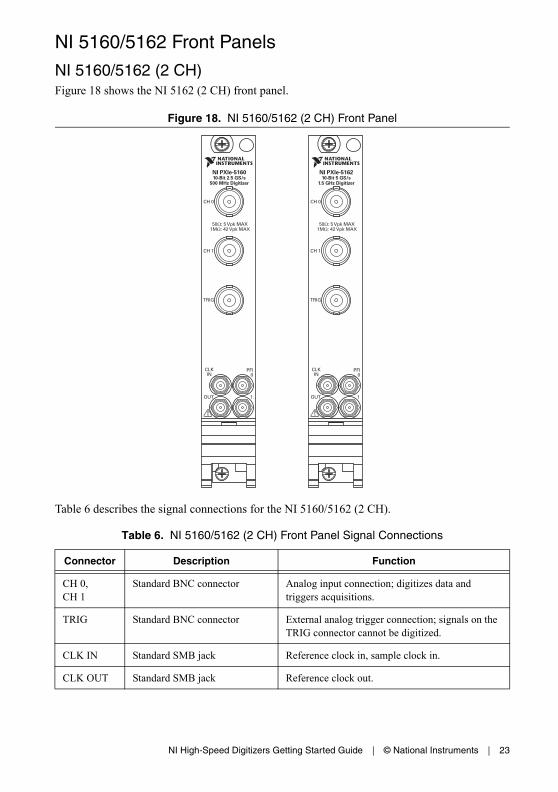
NI 5160/5162 (2 CH)Figure 18 shows the NI 5162 (2 CH) front panel.
Figure 18. NI 5160/5162 (2 CH) Front Panel
Table 6 describes the signal connections for the NI 5160/5162 (2 CH).
Table 6. NI 5160/5162 (2 CH) Front Panel Signal Connections
Connector Description Function
CH 0,CH 1
Standard BNC connector Analog input connection; digitizes data and triggers acquisitions.
TRIG Standard BNC connector External analog trigger connection; signals on the TRIG connector cannot be digitized.
CLK IN Standard SMB jack Reference clock in, sample clock in.
CLK OUT Standard SMB jack Reference clock out.
CH 0
50 : 5 Vpk MAX1M : 42 Vpk MAX
CH 1
TRIG
CLKIN
PFI0
1OUT
NI PXIe-516010-Bit 2.5 GS/s
500 MHz Digitizer
CH 0
50 : 5 Vpk MAX1M : 42 Vpk MAX
CH 1
TRIG
CLKIN
PFI0
1OUT
NI PXIe-516210-Bit 5 GS/s
1.5 GHz Digitizer
24 | ni.com | NI High-Speed Digitizers Getting Started Guide
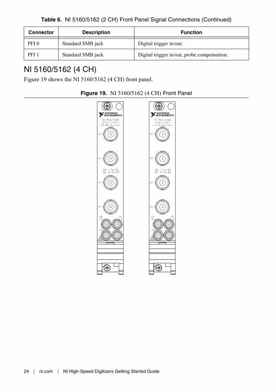
NI 5160/5162 (4 CH)Figure 19 shows the NI 5160/5162 (4 CH) front panel.
Figure 19. NI 5160/5162 (4 CH) Front Panel
PFI 0 Standard SMB jack Digital trigger in/out.
PFI 1 Standard SMB jack Digital trigger in/out, probe compensation.
Table 6. NI 5160/5162 (2 CH) Front Panel Signal Connections (Continued)
Connector Description Function
NI High-Speed Digitizers Getting Started Guide | © National Instruments | 25
Table 7 describes the signal connections for the NI 5160/5162 (4 CH).
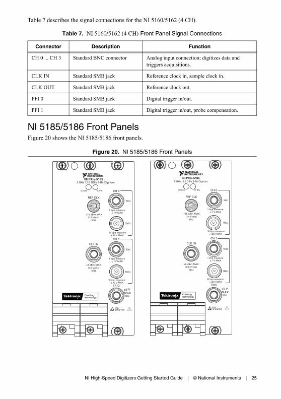
NI 5185/5186 Front PanelsFigure 20 shows the NI 5185/5186 front panels.
Figure 20. NI 5185/5186 Front Panels
Table 7. NI 5160/5162 (4 CH) Front Panel Signal Connections
Connector Description Function
CH 0 ... CH 3 Standard BNC connector Analog input connection; digitizes data and triggers acquisitions.
CLK IN Standard SMB jack Reference clock in, sample clock in.
CLK OUT Standard SMB jack Reference clock out.
PFI 0 Standard SMB jack Digital trigger in/out.
PFI 1 Standard SMB jack Digital trigger in/out, probe compensation.
5 GHz 12.5 GS/s 8-Bit DigitizerNI PXIe-5186
+16 dBm MAX(1.4 Vrms)
50Ω
±5 V MAX
50Ω
50Ω
1MΩ
+9 dBm MAX(0.6 Vrms)
50Ω
50Ω
1MΩ
+16 dBm MAX(1.4 Vrms)
50Ω
±5 V MAX
50Ω
50Ω
1MΩ
+9 dBm MAX(0.6 Vrms)
50Ω
50Ω
1MΩ
3 GHz 12.5 GS/s 8-Bit DigitizerNI PXIe-5185
1 Vpp measure
1 Vpp measure
10 Vpp measure
10 Vpp measure
± 1 V MAX
± 1 V MAX
± 42 V MAX
± 42 V MAX
1 Vpp measure
1 Vpp measure
10 Vpp measure
10 Vpp measure
± 1 V MAX
± 1 V MAX
± 42 V MAX
± 42 V MAX
26 | ni.com | NI High-Speed Digitizers Getting Started Guide
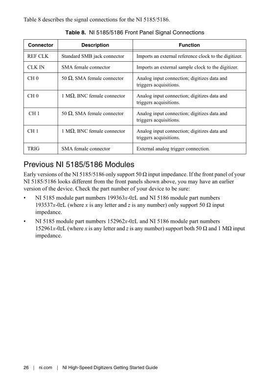
Table 8 describes the signal connections for the NI 5185/5186.
Previous NI 5185/5186 ModulesEarly versions of the NI 5185/5186 only support 50 Ω input impedance. If the front panel of your NI 5185/5186 looks different from the front panels shown above, you may have an earlier version of the device. Check the part number of your device to be sure:
• NI 5185 module part numbers 199363x-0zL and NI 5186 module part numbers 193537x-0zL (where x is any letter and z is any number) only support 50 Ω input impedance.
• NI 5185 module part numbers 152962x-0zL and NI 5186 module part numbers 152961x-0zL (where x is any letter and z is any number) support both 50 Ω and 1 MΩ input impedance.
Table 8. NI 5185/5186 Front Panel Signal Connections
Connector Description Function
REF CLK Standard SMB jack connector Imports an external reference clock to the digitizer.
CLK IN SMA female connector Imports an external sample clock to the digitizer.
CH 0 50 Ω, SMA female connector Analog input connection; digitizes data and triggers acquisitions.
CH 0 1 MΩ, BNC female connector Analog input connection; digitizes data and triggers acquisitions.
CH 1 50 Ω, SMA female connector Analog input connection; digitizes data and triggers acquisitions.
CH 1 1 MΩ, BNC female connector Analog input connection; digitizes data and triggers acquisitions.
TRIG SMA female connector External analog trigger connection.

NI High-Speed Digitizers Getting Started Guide | © National Instruments | 27
NI 5622 Front PanelsFigure 21 shows the NI PXIe-5622 front panels.
Figure 21. NI 5622 Front Panel
Table 9 describes the signal connections for the NI 5622.
Table 9. NI 5622 Front Panel Signal Connections
Connector Description Function
IF IN SMA female connector Analog input connection; digitizes data and triggers acquisitions.
PFI 1 SMB jack connector Digital trigger connection. (Multipurpose PFI line for reference clock in, sample clock in, and digital trigger in/out.)
CLK IN SMA female connector Imports an external reference clock or sample clock to the digitizer.
CLK OUT SMA jack connector Exports the digitizer reference clock or sample clock.
NI PXIe-562216-Bit IF Digitizer
ACCESS ACTIVE
PFI 1
IF IN
CLK IN
CLK OUT
TTL (+5 V MAX)

28 | ni.com | NI High-Speed Digitizers Getting Started Guide
Appendix B: Front Panels for Traditional NI-DAQ (Legacy) DevicesThis appendix describes digitizer front panels and signal connections for the Traditional NI-DAQ (Legacy) device, NI 5620/5621.
NI 5620/5621 Front PanelsFigure 22 shows the NI PXI-5620/5621 front panels.
Figure 22. NI 5620/5621 Front Panels
NI PXI-562164 MS/s Digitizer
INPUT
50 +20 dBm MAX±3 VDC MAX
REF CLK IN
PFI 1
50 +20 dBm MAX±10 VDC MAX
TTL (+5 V MAX)
NI PXI-562064 MS/s Digitizer
INPUT
50 +20 dBm MAX±2 VDC MAX
REF CLK IN
PFI 1
50 +16 dBm MAX±10 VDC MAX
TTL (+5 V MAX)

NI High-Speed Digitizers Getting Started Guide | © National Instruments | 29
Table 10 describes the signal connections for the NI 5620/5621.
Appendix C: Accessory Front PanelsThis appendix describes the front panel and signal connections for the digitizer accessory.
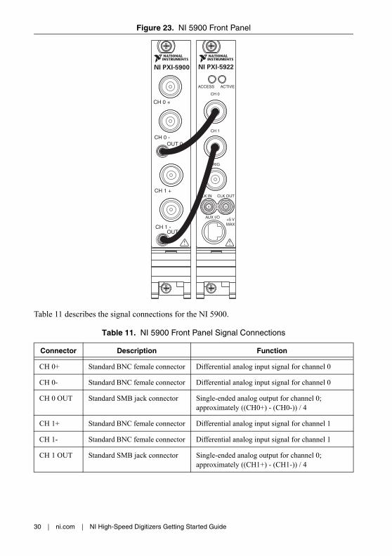
NI 5900 Front PanelFigure 23 shows the NI PXI-5900 differential amplifier front panel and the connections to the NI 5922.
Table 10. NI 5620/5621 Front Panel Signal Connections
Connector Description Function
INPUT Standard SMA female connector Analog input connection; digitizes data and triggers acquisitions.
(NI 5620) 50 Ω, AC coupled.
(NI 5621) 50 Ω, DC coupled.
REF CLK IN
Standard SMA female connector 50 Ω, 10 MHz, AC coupled reference clock input.
PFI 1 Standard SMB jack connector External digital trigger connection.
30 | ni.com | NI High-Speed Digitizers Getting Started Guide
Figure 23. NI 5900 Front Panel
Table 11 describes the signal connections for the NI 5900.
Table 11. NI 5900 Front Panel Signal Connections
Connector Description Function
CH 0+ Standard BNC female connector Differential analog input signal for channel 0
CH 0- Standard BNC female connector Differential analog input signal for channel 0
CH 0 OUT Standard SMB jack connector Single-ended analog output for channel 0; approximately ((CH0+) - (CH0-)) / 4
CH 1+ Standard BNC female connector Differential analog input signal for channel 1
CH 1- Standard BNC female connector Differential analog input signal for channel 1
CH 1 OUT Standard SMB jack connector Single-ended analog output for channel 0; approximately ((CH1+) - (CH1-)) / 4
NI PXI-5922
CH 0 +
CH 0 -OUT 0
NI PXI-5900
CH 1 +
CH 1 -OUT 1
NI High-Speed Digitizers Getting Started Guide | © National Instruments | 31
Appendix D: Troubleshooting
Front Panel ACCESS LED on PXI/PXI Express Module is Off when PXI/PXI Express Chassis is OnIf the ACCESS LED on the digitizer is not lit after you power on the PXI/PXI Express chassis, a problem may exist with the PXI/PXI Express power rails, a hardware device, or the LED.
Note The LEDs may not light until the device has been configured in MAX. Before troubleshooting this issue, verify that the device appears in MAX.
Complete the following steps to troubleshoot this issue:
1. Power off your PXI chassis.
2. Disconnect any signals from the PXI module front panel.
3. Remove the PXI module and inspect for signs of damage. Do not reinstall a damaged device.
4. Reinstall the PXI module as described in section 5. Installing the Hardware.
5. Power on the PXI chassis.
6. Verify that the device appears in MAX.
7. Reset the device in MAX and perform a self-test. For information about performing device resets and self-tests in MAX, refer to section 6. Configuring and Testing in MAX.
8. If the ACCESS LED still fails to light, contact NI Technical Support at ni.com/support.
Back Panel LED on USB Module is Off when Device is Plugged InIf the LED on the digitizer is not lit after it has been plugged into the USB port, a problem may exist with the software installation, the hardware device, or the LED.
Note The LEDs may not light until the device has been configured in MAX. Before troubleshooting this issue, verify that the device appears in MAX.
Complete the following steps to troubleshoot this issue:
1. Unplug the USB digitizer.
2. Disconnect any signals from the USB digitizer front panel.
3. Reinstall the USB device as described in section 5. Installing the Hardware.
4. Verify that the device appears in MAX.
5. Reset the device in MAX and perform a self-test. For information about performing device resets and self-tests in MAX, refer to section 6. Configuring and Testing in MAX.
6. If the back panel LED still fails to light, contact NI Technical Support at ni.com/support.

32 | ni.com | NI High-Speed Digitizers Getting Started Guide
Device Does Not Appear in MAXComplete the following steps if the device does not appear in MAX:
1. In the MAX Configuration pane, click Devices and Interfaces to expand the category.
2. Press <F5> to refresh the list of installed devices.
3. If the device is still not listed, power off the system, verify that the device is correctly installed, and restart.
4. If the device still does not appear under Devices and Interfaces, contact NI Technical Support at ni.com/support.
Device Failed the Self-TestThe MAX self-test performs a brief test of device resources. If the device does not pass the self-test, complete the following steps:
1. Restart your system.
2. Launch MAX and perform the self-test again. If the device still fails the self-test, proceed to step 3.
3. Uninstall and reinstall NI-SCOPE.
4. If the device still fails the self-test, contact NI Technical Support at ni.com/support.
Thermal Shutdown ErrorIf you receive an over temperature (or thermal shutdown) error and your device shuts down, complete the following steps to re-enable your device:
1. Power off the computer or chassis that contains the device.
2. Review the procedure in section 5. Installing the Hardware and make any necessary adjustments to make sure that your device is effectively cooled.
3. Power on the computer or chassis.
Note The thermal shutdown error is reported until the device has cooled to an acceptable operating temperature and has been successfully reset.
Performance Issues Using MXI ConnectionsIf you are using a MXI interface to control a PXI chassis and you encounter performance or initialization issues, refer to the MXI documentation to verify that the MXI interface is properly set up. Software optimization might be necessary.
• (MXI-3) For optimization, select Start»All Programs»National Instruments MXI-3»MXI-3 Optimization. Using a MXI-3 connection without running this application may result in an error message such as the following:
– maximum amount of time exceeded
– internal software error
NI High-Speed Digitizers Getting Started Guide | © National Instruments | 33
If the software optimization application is not installed on your system, use the MXI software media or the National Instruments Driver media included with your kit to install the software. After installation, you may need to restart your computer before running the MXI Optimization Application.
• (MXI-4 and MXI-Express) Optimization is performed automatically by the hardware.
If you continue to have initialization or performance issues, refer to the MXI documentation at Start»All Programs»National Instruments MXI, or visit NI Technical Support at ni.com/support.
Setting Up SMC-Based Devices for Synchronization
Note The following step is required for any type of synchronization involving an SMC-based device, including NI-TClk synchronization. For information about NI-TClk synchronization, refer to NI High-Speed Digitizers Help»Programming»Reference»NI-TClk Synchronization Help.
If you plan to share triggers and/or clocks for the purpose of synchronizing SMC-based devices, you must identify or configure certain components in MAX.
(PXI and PXI Express Modules) You must identify the PXI/PXI Express system controller by completing the following steps:
1. In the MAX configuration tree,
a. Right-click PXI System»Identify As.
b. Select your controller from the list. For example, select External PC if you are using a MXI controller in an external PC.
2. Expand the PXI System tree and right-click the name of the chassis you are using.
(PCI Devices) You must configure the RTSI cable by completing the following steps:
1. Connect a RTSI cable between the PCI devices to physically share triggers and/or clocks.
2. In the MAX configuration tree,
a. Right-click NI-DAQmx Devices.
b. Select Create New NI-DAQmx Device»RTSI Cable.
c. Right-click the RTSI cable, then select the device to add to the RTSI cable.
34 | ni.com | NI High-Speed Digitizers Getting Started Guide
Appendix E: Where to Go for SupportThe National Instruments Web site is your complete resource for technical support. At ni.com/support you have access to everything from troubleshooting and application development self-help resources to email and phone assistance from NI Application Engineers.
A Declaration of Conformity (DoC) is our claim of compliance with the Council of the European Communities using the manufacturer’s declaration of conformity. This system affords the user protection for electromagnetic compatibility (EMC) and product safety. You can obtain the DoC for your product by visiting ni.com/certification. If your product supports calibration, you can obtain the calibration certificate for your product at ni.com/calibration.
National Instruments corporate headquarters is located at 11500 North Mopac Expressway, Austin, Texas, 78759-3504. National Instruments also has offices located around the world to help address your support needs. For telephone support in the United States, create your service request at ni.com/support and follow the calling instructions or dial 512 795 8248. For telephone support outside the United States, visit the Worldwide Offices section of ni.com/niglobal to access the branch office Web sites, which provide up-to-date contact information, support phone numbers, email addresses, and current events.

Refer to the NI Trademarks and Logo Guidelines at ni.com/trademarks for more information on National Instruments trademarks. Other product and company names mentioned herein are trademarks or trade names of their respective companies. For patents covering National Instruments products/technology, refer to the appropriate location: Help»Patents in your software, the patents.txt file on your media, or the National Instruments Patents Notice at ni.com/patents. You can find information about end-user license agreements (EULAs) and third-party legal notices in the readme file for your NI product. Refer to the Export Compliance Information at ni.com/legal/export-compliance for the National Instruments global trade compliance policy and how to obtain relevant HTS codes, ECCNs, and other import/export data.
© 2003–2013 National Instruments. All rights reserved.

2013年 5月371133T-01
スタートアップガイドNI高速デジタイザこのドキュメントでは、NI高速デジタイザおよびアクセサリの取り付け、構成、テスト、また NI-SCOPE計測器ドライバソフトウェアによるプログラミング方法について説明します。 このドキュメントは、NI 5105、NI 5114、NI 5122、NI 5124、NI 5132、NI 5133、NI 5142、NI 5152、NI 5153、NI 5154、NI 5160、NI 5162、NI 5185、NI 5186、NI 5620、NI 5621、NI 5622、NI 5900、および NI 5922に適用します。
機能の詳細やプログラミング方法については、『NI 高速デジタイザヘルプ』を参照してください。 デバイス仕様の詳細については、デバイスに付属する仕様書を参照してください。 これらのドキュメントは、スタート→すべてのプログラム→ National Instruments→ NI-SCOPE→ドキュメントからアクセスできます。 (Windows 8) NI起動ツールをクリックして、表示されるウィンドウで NI-SCOPE→ドキュメントを選択します。
最新のドキュメントは、ni.com/manualsで入手できます。 NI-SCOPEの最新バージョンは、ni.com/downloadsで入手できます。
目次安全対策と電磁両性について..............................................................................................................21. システム要件を確認する .......................................................................................................................22. デバイスをパッケージから取り出す ...............................................................................................33. キットの内容を確認する .......................................................................................................................3
その他必要となるもの .......................................................................................................................44. ソフトウェアをインストールする ....................................................................................................45. ハードウェアを取り付ける...................................................................................................................5
PXI/PXI Expressモジュール ..............................................................................................................5NI PXIe-5185/5186モジュール........................................................................................................7
NI PXIe-5185/5186起動時の動作 .........................................................................................8PCIデバイス............................................................................................................................................8USBデバイス ...........................................................................................................................................10
USBケーブルストレインリリーフ ......................................................................................11USB-5132/5133を取り付ける ..........................................................................................................12
デスクトップでの使用..............................................................................................................12DINレールマウント ...................................................................................................................13パネルに取り付ける...................................................................................................................13
Windowsのデバイス認識.................................................................................................................146. MAXでの構成とテスト ..........................................................................................................................14
2 | ni.com | NI高速デジタイザ スタートアップガイド
7. デバイスをプログラミングする.........................................................................................................16対話式にデータを集録する .............................................................................................................16プログラムでデータを集録する....................................................................................................16NI-SCOPEサンプル ..............................................................................................................................17
8. 測定をう ....................................................................................................................................................17付録 A: SMC対応デバイスおよび USBデバイスのフロントパネル .....................................18
NI 5105フロントパネル ....................................................................................................................19NI 5114フロントパネル ....................................................................................................................20NI 5122/5124/5142/5922 フロントパネル ................................................................................21NI 5132/5133 フロントパネル ........................................................................................................23NI 5152/5153/5154 フロントパネル ............................................................................................24NI 5160/5162 フロントパネル ........................................................................................................25
NI 5160/5162(2 CH)................................................................................................................25NI 5160/5162(4 CH)................................................................................................................26
NI 5185/5186 フロントパネル ........................................................................................................27旧バージョン NI 5185/5186モジュール ..........................................................................28
NI 5622フロントパネル ....................................................................................................................29付録 B: 従来型 NI-DAQ(レガシー)用デバイスのフロントパネル .....................................30
NI 5620/5621 フロントパネル ........................................................................................................30付録 C: アクセサリのフロントパネル .................................................................................................31
NI 5900フロントパネル ....................................................................................................................32付録 D: トラブルシューティング ...........................................................................................................33
PXI/PXI Expressシャーシの電源を入れても PXI/PXI Expressモジュールのフロントパネル ACCESS LEDが点灯しない .......................................................................33
USBモジュールが接続されていても USBモジュールのバックパネル LEDが点灯しない ...............................................................................................33デバイスがMAXで表示されない.................................................................................................34デバイスがセルフテストで不合格になる ................................................................................34過熱遮断エラー......................................................................................................................................34MXI接続時におけるパフォーマンスの問題 ............................................................................35同期をうための SMC対応デバイスの設定.........................................................................35
付録 E: サポート情報.....................................................................................................................................36
安全対策と電磁両性について安全規格の詳細については、『はじめにお読みください : 安全対策と電磁両性について』を参照してください。 このドキュメントをオンラインで入手するには、ni.com/manualsにアクセスしてドキュメントタイトルで検索してください。
製品に特化した取り付け方法または特定レベルの電磁両性能を実現するための構成など、その他の電磁両性に関する詳細は、各製品の仕様を参照してください。
1. システム要件を確認するNI 高速デジタイザを NI-SCOPEドライバと一緒に使用するには、特定の要件を満たすシステムが必要です。 最低要件、推奨要件、サポートされている開発環境(ADE)については、NI-SCOPEのメディアに含まれる『NI-SCOPE Readme』を参照してください。

NI高速デジタイザ スタートアップガイド | © National Instruments | 3
メモ NI-SCOPEをインストール済みのコンピュータでは、スタート→すべてのプログラム→ National Instruments→ NI-SCOPE→ドキュメントを選択して『NI-SCOPE Readme』ファイルを閲覧できます。 (Windows 8) NI起動ツールをクリックして、表示されるウィンドウでNI-SCOPE→ドキュメントを選択します。
2. デバイスをパッケージから取り出すNI高速デジタイザは、静電気放電(ESD)防止のため静電気防止用袋に梱包されて出荷されます。 デジタイザを袋から取り出す前に、袋をシャーシの属部分に接触させ、静電気を除去してください。
注意 デジタイザを取り扱う際は、接地ストラップを装着したり接地された属に触れるなど、必ず体に対して接地対策をってください。 また、デジタイザの露出したピンや回路に触れないように注意してください。
袋からデジタイザを取り出し、梱包材とゴムのネジカバー(PXI/PXI Expressデバイスのみ)を取り除き、デジタイザにゆるんでいる部品や破損箇所がないかを調べます。 デジタイザに破損がある場合は、ナショナルインスツルメンツまでご連絡ください。 破損しているデジタイザはコンピュータやシャーシに取り付けないでください。
デジタイザは、使用していない時は静電気防止用袋に入れて保管してください。
3. キットの内容を確認するNI高速デジタイザのキットには、以下が含まれます。
ご注文された NI高速デジタイザまたはアクセサリ
NI-SCOPEドライバソフトウェアメディアを含む、NI-SCOPE計測器ドライバのケース(DVDサイズ)
その他、付属するアイテム– デバイス仕様書– 『はじめにお読みください : 安全対策と電磁両性について』– 『NI 高速デジタイザスタートアップガイド』(本書)– 『強制空冷の維持について』(SMC対応デバイスのみ)– NIスペクトル計測ツールキットメディア(特定の SMC対応デバイスキット
のみ)– USBケーブル(USBデバイスのみ)– NI SignalExpressメディア(USBデバイスのみ)
メモ SMC対応デバイスは、ナショナルインスツルメンツ SMC(Synchronization and Memory Core)アーキテクチャに基づいています。 詳細については、『NI 高速デジタイザヘルプ』を参照してください。

4 | ni.com | NI高速デジタイザ スタートアップガイド
その他必要となるものキットに含まれるアイテム以外に、以下が必要となります。
1/8 in. マイナスドライバー
以下のうちいずれか– (PXIデバイス) PXIシャーシ、PXI/SCXIコンビネーションシャーシ、または
PXI/CompactPCIシャーシ、コントローラおよびシャーシのドキュメント– (PXI Expressデバイス) PXI Expressシャーシ、コントローラおよびシャーシの
ドキュメント– (USBデバイス) デスクトップまたはノートブック PCおよびドキュメント– (PCIデバイス) デスクトップコンピュータおよびドキュメント
メモ PCIデバイスで NI-TClkによる同期をう場合は、RTSIケーブルを使用して PCIデバイスを接続する必要があります。 詳細については、NI 高速デジタイザヘルプ→プログラミング→リファレンス→ NI-TClk同期ヘルプを参照してください。
4. ソフトウェアをインストールする注意 ハードウェアは、必ずソフトウェアをインストールした後に取り付けてください。
ソフトウェアをインストールするには、以下の手順に従ってください。1. (オプション) LabVIEWやサードパーティから提供されているツールなどのアプ
リケーション開発環境(ADE)を使用する場合、初めに開発環境をインストールします。 ADEは、必ず NI-SCOPE計測器ドライバより先にインストールしてください。
2. DVDドライブに NI-SCOPEメディアを挿入して、NI-SCOPEをインストールします。 表示されるウィンドウからソフトウェアをインストールをクリックしてください。
メモ インストールウィンドウが自動的に起動しない場合は、DVDドライブを開いて setup.exeをダブルクリックします。
3. インストール画面の指示に従います。
メモ アクセス /セキュリティメッセージが表示される場合があります。 画面の指示に従って、インストールを完了します。
4. インストールが完了すると、再起動、シャットダウン、または後で再起動するかどうかのダイアログボックスが表示されます。 再起動を選択します。
NI高速デジタイザ スタートアップガイド | © National Instruments | 5
5. LabVIEW Real-Timeモジュールを実するシステムを使用する場合は、Measurement & Automation Explorer (MAX)にて NI-SCOPEをターゲットにダウンロードします。 詳細については、MAXでヘルプ→ヘルプトピック→リモートシステムを選択して、『MAXリモートシステムヘルプ』を参照してください。
5. ハードウェアを取り付けるこのセクションでは、PXI/PXI Express、PCI、および USBプラットフォームのハードウェアを取り付ける方法について説明します。
メモ ハードウェアを取り付ける前に、必ずソフトウェアをインストールしてください。
ESDや汚れによる破損を避けるために、デバイスを取り扱う際には、デバイスの端や属ブラケット部分以外には触れないでください。 詳細については、『はじめにお読みください : 安全対策と電磁両性について』を参照してください。
注意 USBデバイスを使用する場合を除き、ハードウェアを取り付ける前に必ずコンピュータやシャーシの電源を切ってください。
PXI/PXI ExpressモジュールNI PXI/PXI Expressモジュールは精密機器であるため、取り扱いには注意が必要です。 このモジュールを、使用温度範囲または使用湿度範囲を超える環境に配置しないでください。 また、エアダスターを使用して、モジュールに付着するほこりを取り除いてください。 手入れ時に溶媒や液体は使用しないでください。
PXIモジュールは、グリフ(円で囲まれたスロット番号)の記載がある任意の PXIスロットに取り付けることができます。
PXI Expressモジュールは、シャーシ内の PXI Expressスロットに取り付けることができます。 PXI Expressスロットを示す表記については、シャーシのドキュメントを参照してください。
PXI/PXI Expressモジュールを取り付けるには、以下の手順に従ってください。1. モジュールを取り付ける前に、PXI/PXI Expressシャーシの電源を切り、プラグを
抜きます。2. PXI/PXI Expressシャーシにファンの速度設定が複数ある場合には、HIGHに設定
します。3. PXI/PXI Expressシャーシを配置する際は、吸排気口が遮蔽されないよう注意しま
す。 詳細については、各シャーシのドキュメントを参照してください。4. モジュールの着脱用ハンドルがラッチされていない状態(下向き)になっている
ことを確認します。

6 | ni.com | NI高速デジタイザ スタートアップガイド
5. モジュールの脱着ハンドル部分を持ちながら、図 1(PXIモジュール)、図 2(PXI Expressモジュール)、図 3(NI PXIe-5185/5186モジュール)のようにモジュールを使用可能なスロットに差し込みます。 モジュールの底部がシャーシのガイドに固定されていることを確認します。
6. モジュールを完全にシャーシに押し込み、脱着ハンドルを引き上げて固定します。
7. モジュールのフロントパネルの上下を取り付けネジで固定します。 両方のネジが適切に締められていないと、パフォーマンスに影響が出る恐れがあります。
8. PXI/PXI Expressシャーシファンが動作し、通気を妨げるようなほこりや汚れがついていないことを確認します。
9. モジュールを動作する前に、フィラーパネルまたはスロットブロッカー(ni.comで購入可能)を使用して、すべての空のシャーシスロットに取り付けてください。
10. シャーシの電源ケーブルプラグを差し込み、電源を投入します。
図 1. PXIモジュールの取り付け
図 2. PXI Expressモジュールの取り付け
1 PXIシャーシ2 脱着ハンドル(下向きになっていること)
3 ネジ4 NI PXIモジュール
1 PXI Expressシャーシ2 脱着ハンドル
3 ネジ4 NI PXI Expressモジュール
5 シャーシスロットマーク
3
2
4 NI PXI-1042
1
34
2
1
NI PXIe-1062Q
5

NI高速デジタイザ スタートアップガイド | © National Instruments | 7
NI PXIe-5185/5186モジュール「PXI/PXI Expressモジュール」セクションの取り付け手順に従って、NI PXIe-5185/5186モジュールをシャーシの PXI Expressスロットに取り付けます。
メモ 図 3に示された 2つの NI 5185/5186モジュール上の PXI Expressコネクタは、2つの隣接した PXI Expressスロットのシャーシバックプレーンに接続する必要があります。
図 3. NI PXIe-5185/5186コネクタ
1 PXI Expressコネクタ 2 NI PXIe-5186モジュール
1
2
8 | ni.com | NI高速デジタイザ スタートアップガイド
図 4. NI 5185/5186の取り付け
NI PXIe-5185/5186起動時の動作シャーシに初めて NI 5185/5186を取り付けると、NI-SCOPEドライバがデバイス認識ウィザードを起動します。 ウィザードでの作業が完了すると、NI 5185/5186モジュールは約 5〜 10分間の初期化処理をいます。 初期化処理が完了してからモジュールを使用する必要があります。
メモ Access LEDは、モジュールが構成できる状態になると緑色になります。
初期化処理は、その後 NI 5185/5186を使用するたびに実されますが、デバイス認識ウィザードは各ブートサイクルでは表示されません。 モジュールは、オペレーティングシステムが NI-SCOPEドライバをロードした後で初期化処理を開始します。
PCIデバイスPCIデバイスを取り付けるには、以下の手順に従ってください。1. コンピュータの電源を切り、電源プラグを抜きます。2. PCのカバーを外します。
1 PXI Expressシャーシ2 脱着ハンドル
3 ネジ4 NI PXIe-5185/5186モジュール
5 シャーシスロットマーク
NI PXIe-1062Q3
4
5
2
1

NI高速デジタイザ スタートアップガイド | © National Instruments | 9
3. 図 5に示されているように、空いている PCIスロットにデバイスを差し込みます。
図 5. PCIの取り付け
ヒント 通気の確保やデバイスの寿命に影響を与えないために、隣接している PCIスロットは空けてください。
4. デバイスを PCIシャーシにネジで固定します。
注意 デバイスのフロントパネルは必ず PCIスロットにネジで固定してください。これは、機械的な安定性と確実な接地接続を確保するために重要です。 デバイスを適切に固定しないと、デバイスの確度に影響する場合があります。
(SMC対応デバイス) コンピュータの種類によっては、PCIデバイスを固定するためにプラスチックのレバーを使用するものもあります。このような場合、レバーは使用せずに、取り外す必要があります。 キットに含まれているネジを使用してデジタイザを固定してください。 ネジで固定することができない場合は、別のコンピュータシャーシを使用する必要があります。
5. PCのカバーを元どおりに取り付けます。6. コンピュータの電源プラグを差し込み、電源を投入します。7. (SMC対応デバイス) 拡散スペクトルクロックが PCの BIOSで有効になっている
か確認します。 確認する方法については、PCのドキュメントを参照してください。
メモ SMC対応デバイスでは、拡散スペクトルクロックは、タイミングクロック信号が狭い周波数範囲全体に渡るよう、クロック信号を分散します。 拡散スペクトルクロックを無効にすると、デバイスの確度に影響が出る可能性があります。
1 NI PCIデバイス 2 PCIスロット 3 PC
12
3

10 | ni.com | NI高速デジタイザ スタートアップガイド
USBデバイスUSBデバイスを取り付けるには、図 6のように USBケーブルを PCおよびデジタイザに接続します。
図 6. USBの取り付け
1 ノートブック PC 2 NI USB高速デジタイザ 3 USBケーブル
2
1
3
NI高速デジタイザ スタートアップガイド | © National Instruments | 11
USBケーブルストレインリリーフUSBケーブルには、以下の 2つのストレインリリーフオプションがあります。• 固定溝を使用 : USBケーブルを、USBデバイスの下側にある 2つの溝のいずれか
に押し込みます。 図 7のように、USBケーブルのサイズに一致する溝を使用します。
• ケーブルタイを使用 : 図 7のように、USBデバイスの下側にあるケーブルタイ取り付けバーにケーブルタイを通し、USBケーブルを固定します。
図 7. USBケーブルストレインリリーフオプション
1 固定溝を使用2 ケーブルタイを使用3 USBケーブルストレインリリーフ用溝(大)4 USBケーブルストレインリリーフ用溝(小)
5 USBケーブル6 ケーブルタイ7 ケーブルタイ取り付けバー
4
3
5
5
7
6
or
1 2

12 | ni.com | NI高速デジタイザ スタートアップガイド
USB-5132/5133を取り付けるNI USB-5132/5133をデスクトップで使用、または標準 DINレールまたはパネルに取り付けることができます。
デスクトップでの使用NI USB-5132/5133の底部には、他の NI USB-5132/5133デバイスを積み重ねることができるように溝が付いています。
デスクトップで使用する場合にデバイスを安定させるには、図 8のように、付属の滑り止め用の脚をデバイスの下側に貼り付けます。
メモ NI USB-5132/5133をパネルに取り付ける場合、または他のNI USB-5132/5133デバイスの上に積み重ねる場合は、ゴム脚は使用しないでください。
図 8. ゴム脚を USB-513xに取り付ける
1 NI USB高速デジタイザ 2 プラスチックガイド 3 ゴム脚
3
2
2
1
NI高速デジタイザ スタートアップガイド | © National Instruments | 13
DINレールマウントDINレールマウントキット(製品番号 : 779689-01、USB-513x キットには付属しません)は、USB-513x製品群を標準 DINレールに取り付けるためのアクセサリです。
メモ 「USBケーブルストレインリリーフ」セクションの説明どおり、USB-513xを DINレールに取り付ける前に、抜け防止対策をいます。
パネルに取り付けるUSB-513xをボードまたはパネルに取り付けるには、図 9を参照しながら以下の手順に従ってください。
図 9. USB-513xをパネルに取り付ける
メモ デバイスをパネルに取り付ける場合は、ゴム脚を USB-513xに取り付けないでください。
メモ 「USBケーブルストレインリリーフ」セクションの説明どおり、USB-513x をパネルに取り付ける前に、抜け防止対策をいます。
1. 技術サポートデータベースのドキュメント「USB-4065/5132/5133/6509 Panel Mounting Template」に添付されているパネル取り付け用テンプレートの PDFをダウンロードして印刷します。 技術サポートデータベースのドキュメントを参照するには、ni.com/jp/infoで「rd3233」のコードを入します。
14 | ni.com | NI高速デジタイザ スタートアップガイド
2. テンプレートを使用して、パネル上下に印を付けます。 印は、162 mm(6.375 in.)間隔です。
3. USBケーブルを USB-513xのコネクタから外します。4. #8またはM4ネジをパネルの下の位置にネジ止めします。5. USB-513xの底部ネジ用ノッチに合わせて、USB-513xをネジの上に設置します。6. #8またはM4ネジを USB-513x上部のネジ穴に通してパネルにネジ止めします。
Windowsのデバイス認識ハードウェアの取り付け後に初めてコンピュータを起動すると、Windowsによって新しく取り付けられたデバイスが認識されます。 一部のWindowsシステムでは、インストールされたすべての NIデバイスに対して、新しいハードウェアの検索ウィザードが起動します。 デフォルトでは、デバイスに最適なドライバを検索する(推奨)が選択されています。 次へまたははいをクリックして、各デバイスのソフトウェアをインストールします。
メモ (USBデバイス)NI USB-5132/5133を初めて取り付けた場合、Windowsが新しいデバイスを認識します。 表示されるダイアログボックスで次へをクリックし、インストールを完了します。
Windowsが新しく取り付けられたデバイスを認識すると、以下のオプションを選択するためのダイアログボックスが表示されます。表示されるオプションは、システムにインストールされているデバイスとソフトウェアによって異なります。• NI SignalExpressを使用してこのデバイスの測定を開始するを選択すると
SignalExpressが開きます。• このデバイスを対話的に使用するを選択すると NI-SCOPEソフトフロントパネル(SFP)が開きます。
• このデバイスでアプリケーションを開始するを選択すると LabVIEWが開きます。
• デバイスを構成しテストするを選択すると、MAXが開き、デバイスの構成を設定できます。
• 何もしないを選択すると、デバイスの認識状態は維持されますが、アプリケーションは起動しません。
6. MAXでの構成とテストメモ (NI 5185/5186) NI 5185/5186をシャーシに取り付けた後、 Access LEDは NI 5185/5186がデバイスのファームウェアを構成してデバイスを初期化している間色に点灯します。 この間、ユーザはデバイスにアクセスすることはできません。 Access LEDが緑色に点灯すると、MAXでのデバイス構成を開始できます。

NI高速デジタイザ スタートアップガイド | © National Instruments | 15
1. デスクトップ上のMeasurement & Automationアイコンをダブルクリックして、MAXを開きます。 図 10は、MAX構成ペーンを示します。
図 10. MAX構成ペーン
2. デバイスとインタフェースを展開して、インストールされているデバイスの一覧を表示します。 LabVIEW Real-Timeモジュールと共にデジタイザを使用している場合、リモートシステムを展開します。 ターゲットの IPアドレスまたは名前を検索し、デバイスとインタフェースを展開します。
3. デバイスが表示されていない場合は、<F5>を押して画面を更新します。 それでも表示されない場合は、「5. ハードウェアを取り付ける」のセクションの手順を再度繰り返してください。 MAXの使用方法については、MAXのヘルプファイルを参照してください。
メモ Windows 8(64ビット)、Windows 7(64ビット)、およびWindows Vista(64ビット)は従来型 NI-DAQ(レガシー)デバイスをサポートしません。 ご使用のデジタイザと互換性のあるオペレーティングシステムについては、『NI-SCOPE Readme』を参照してください。
4. MAXで割り当てられたデバイス番号またはデバイス名を記録します。この識別子はデバイスのプログラミング時に必要となります。
5. デバイスのセルフテストを実してインストールを検証します。• デバイスを右クリックして、セルフテストを選択します。• (従来型 NI-DAQ(レガシー )デバイス) デバイスを右クリックし、構成を選択
し、リソース確認を選択します。 ダイアログボックスが開き、デバイスのテストの結果が表示されます。
メモ デバイスのセルフテストが不合格になった場合は、「5. ハードウェアを取り付ける」のセクションの手順を再度ってください。 それでも不合格になる場合は、ナショナルインスツルメンツの技術サポートのウェブサイト(ni.com/support)を参照してください。

16 | ni.com | NI高速デジタイザ スタートアップガイド
6. デバイスのテストパネルを実して信号を確認します。a. デジタイザに信号を接続し、その信号に対して適切な範囲、入制限、サン
プリングレート、サンプルモードなどのデバイスパラメータを選択します。b. テストパネルにアクセスします。
• デバイスを右クリックして、テストパネルを選択します。 • (従来型 NI-DAQ[レガシー ]デバイス)構成ウィンドウでテストパネルを
実をクリックします。
メモ すべての NIデジタイザにはセルフキャリブレーション機能が搭載されています。 NI-SCOPEと ADEを使用してプログラミングする方法と、NI-SCOPEソフトフロントパネル(SFP)またはMAXのいずれかを使用する 2つの方法でこの機能を実できます。住利型 NI-DAQ(レガシー)デバイスではMAXを使用したセルフキャリブレーションを実することはできません。
7. デジタイザの構成とテストが完了したらMAXを終了します。
7. デバイスをプログラミングするNI-SCOPEソフトフロントパネルを使用した対話式集録、または NI-SCOPE計測器ドライバを使用したプログラミング方法でデータを集録できます。 また、NI-SCOPEのサンプルを実して、デジタイザの機能を検証することができます。
対話式にデータを集録するNI-SCOPE SFPを起動するには、スタート→すべてのプログラム→ National Instruments→ NI-SCOPE→ SCOPEソフトフロントパネルを選択します。 (Windows 8) NI起動ツールをクリックして、表示されるウィンドウで NI-SCOPE→ソフトフロントパネルを選択します。 NI-SCOPE SFPでは、各制御器に関する詳細ヘルプを表示することができます。
プログラムでデータを集録するADEでデジタイザをプログラミングするには、NI-SCOPEを使用します。 特定の ADEでデータを集録する方法についての詳細は、『NI高速デジタイザヘルプ』の NI-SCOPE 入門セクション(スタート→すべてのプログラム→ National Instruments→NI-SCOPE→ドキュメント→ NI高速デジタイザヘルプ)を参照してください。 (Windows 8) NI起動ツールをクリックして、表示されるウィンドウで NI-SCOPE→ドキュメント→ NI 高速デジタイザヘルプを選択します。
ヒント NI-SCOPE Cのサンプルを変更してMicrosoft Visual C/C++でアプリケーションを作成することができ、その場合、必要なインクルードファイルおよびライブラリファイルはすべて自動的にプロジェクトに追加されます。 すべての必要なインクルードファイルおよびライブラリファイルを手作業でプロジェクトに追加したい場合は、『NI 高速デジタイザヘルプ』
NI高速デジタイザ スタートアップガイド | © National Instruments | 17
の「Microsoft Visual Cおよび C++でアプリケーションを作成する」トピックを参照してください。
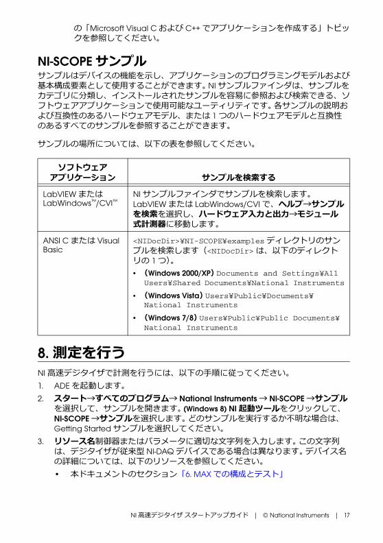
NI-SCOPEサンプル サンプルはデバイスの機能を示し、アプリケーションのプログラミングモデルおよび基本構成要素として使用することができます。 NIサンプルファインダは、サンプルをカテゴリに分類し、インストールされたサンプルを容易に参照および検索できる、ソフトウェアアプリケーションで使用可能なユーティリティです。 各サンプルの説明および互換性のあるハードウェアモデル、または 1つのハードウェアモデルと互換性のあるすべてのサンプルを参照することができます。
サンプルの場所については、以下の表を参照してください。
8. 測定をうNI高速デジタイザで計測をうには、以下の手順に従ってください。1. ADEを起動します。2. スタート→すべてのプログラム→ National Instruments→ NI-SCOPE→サンプル
を選択して、サンプルを開きます。 (Windows 8) NI起動ツールをクリックして、NI-SCOPE→サンプルを選択します。 どのサンプルを実するか不明な場合は、Getting Startedサンプルを選択してください。
3. リソース名制御器またはパラメータに適切な文字列を入します。 この文字列は、デジタイザが従来型 NI-DAQデバイスである場合は異なります。 デバイス名の詳細については、以下のリソースを参照してください。• 本ドキュメントのセクション「6. MAXでの構成とテスト」
ソフトウェアアプリケーション サンプルを検索する
LabVIEWまたはLabWindows™/CVI™
NIサンプルファインダでサンプルを検索します。 LabVIEWまたは LabWindows/CVIで、ヘルプ→サンプルを検索を選択し、ハードウェアと出→モジュール式計測器に移動します。
ANSI Cまたは Visual Basic
<NIDocDir>¥NI-SCOPE¥examplesディレクトリのサンプルを検索します(<NIDocDir>は、以下のディレクトリの 1つ)。• (Windows 2000/XP) Documents and Settings¥All
Users¥Shared Documents¥National Instruments
• (Windows Vista) Users¥Public¥Documents¥National Instruments
• (Windows 7/8) Users¥Public¥Public Documents¥National Instruments
18 | ni.com | NI高速デジタイザ スタートアップガイド
• NI 高速デジタイザヘルプ→プログラミング→リファレンス→ NI-SCOPE LabVIEWリファレンス→ VI→ niScope初期化
• NI 高速デジタイザヘルプ→プログラミング→リファレンス→ NI-SCOPE Function Reference Help→ Functions→ niScope_init
4. 入信号を集録する際に、必要に応じてパラメータを調整します。5. 集録する信号を、デジタイザの入チャンネルの 1つに接続します。 接続方法の
詳細については、「付録 A: SMC対応デバイスおよび USBデバイスのフロントパネル」または「付録 B: 従来型 NI-DAQ(レガシー)用デバイスのフロントパネル」を参照してください。
6. サンプルプログラムを実します。
付録 A: SMC対応デバイスおよび USBデバイスのフロントパネルこの付録では、SMC対応デバイスおよび USBデバイス NI 5105、NI 5114、NI 5122、NI 5124、NI 5132、NI 5133、NI 5142、NI 5152、NI 5153、NI 5154、NI 5160、NI 5162、NI 5185、NI 5186、NI 5622、および NI 5922デジタイザのフロントパネルと信号接続について説明します。
NI高速デジタイザ スタートアップガイド | © National Instruments | 19
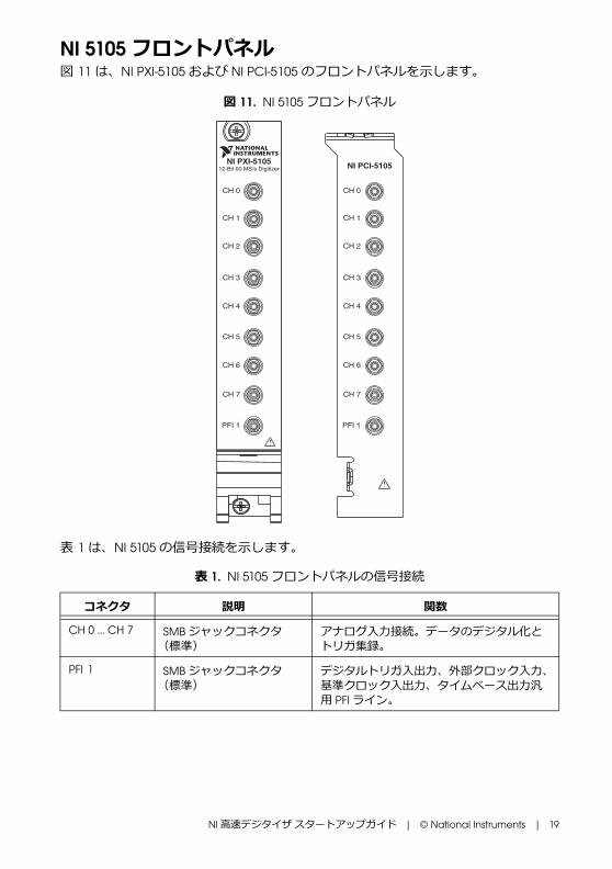
NI 5105フロントパネル図 11は、NI PXI-5105および NI PCI-5105のフロントパネルを示します。
図 11. NI 5105フロントパネル
表 1は、NI 5105の信号接続を示します。
表 1. NI 5105 フロントパネルの信号接続
コネクタ 説明 関数
CH 0 ... CH 7 SMBジャックコネクタ(標準)
アナログ入接続。データのデジタル化とトリガ集録。
PFI 1 SMBジャックコネクタ(標準)
デジタルトリガ入出、外部クロック入、基準クロック入出、タイムベース出汎用 PFIライン。
NI PXI-510512-Bit 60 MS/s Digitizer
PFI 1
CH 0
CH 1
CH 2
CH 3
CH 4
CH 5
CH 6
CH 7
PFI 1
CH 0
CH 1
CH 2
CH 3
CH 4
CH 5
CH 6
CH 7
NI PCI-5105

20 | ni.com | NI高速デジタイザ スタートアップガイド
NI 5114フロントパネル図 12は、NI PXI-5114および NI PCI-5114のフロントパネルを示します。 AUXコネクタのピン配列情報については、図 14を参照してください。
図 12. NI 5114フロントパネル
表 2は、NI 5114の信号接続を示します。
表 2. NI 5114 フロントパネルの信号接続
コネクタ 説明 機能
CH 0、CH 1
BNCメスコネクタ(標準) アナログ入接続。データのデジタル化とトリガ集録。
TRIG BNCメスコネクタ(標準) 外部アナログトリガ接続。TRIGコネクタに接続されている信号のデジタル化は不可。
TRIG
CH 0
CH 1
AUX I/O+5 VMAX
CLK IN
NI PCI-5114
CH 0
CH 1
CLK IN
AUX I/O
TRIG
NI PXI-5114
NI高速デジタイザ スタートアップガイド | © National Instruments | 21
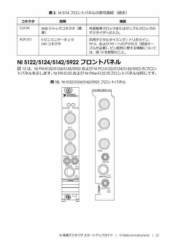
NI 5122/5124/5142/5922 フロントパネル図 13は、NI PXI-5122/5124/5142/5922および NI PCI-5122/5124/5142/5922のフロントパネルを示します。 NI PXI-5122および NI PXIe-5122のフロントパネルは同じです。
図 13. NI 5122/5124/5142/5922 フロントパネル
CLK IN SMBジャックコネクタ(標準)
外部基準クロックまたはサンプルクロックのデジタイザへの入。
AUX I/O 9ピンミニサーキュラDINコネクタ
汎用デジタルタイミング /トリガライン、PFI 0、および PFI 1へのアクセス(別途ケーブルが必要)。 ピン配列に関する情報については、図 14を参照のこと。
表 2. NI 5114 フロントパネルの信号接続 (続き)
コネクタ 説明 機能

22 | ni.com | NI高速デジタイザ スタートアップガイド
表 3は、NI 5122/5124/5142/5922の信号接続を示します。
9ピン DINコネクタピンの割り当ては、図 14のとおりです。
図 14. NI 5114/5122/5124/5142/5922の 9ピン DINコネクタピンの割り当て
表 3. NI 5122/5124/5142/5922フロントパネルの信号接続
コネクタ 説明 機能
CH 0、CH 1
BNCメスコネクタ(標準) アナログ入接続。データのデジタル化とトリガ集録。
TRIG BNCメスコネクタ(標準) 外部アナログトリガ接続。TRIGコネクタに接続されている信号のデジタル化は不可。
CLK IN SMBジャックコネクタ(標準)
(NI 5122/5124/5142) デジタイザへの外部基準クロックもしくはサンプルクロック入。
(NI 5922) デジタイザへの外部基準クロック入。
CLK OUT SMBジャックコネクタ(標準)
(NI 5122/5124/5142) 基準クロックまたはサンプルクロック出。
(NI 5922) 基準クロック出。
AUX I/O 9ピンミニサーキュラDINコネクタ
汎用デジタルタイミング /トリガライン、PFI 0、および PFI 1へのアクセス(別途ケーブルが必要)。 ピン配列に関する情報については、図 14を参照のこと。
1 +5 V (ヒューズ付き )2 GND3 予約済み
4 予約済み5 予約済み6 PFI 1
7 予約済み8 予約済み9 PFI 0
4
3
5
6
7
8
9
1
2

NI高速デジタイザ スタートアップガイド | © National Instruments | 23
NI 5132/5133 フロントパネル図 15は、NI USB-5132および NI USB-5133のフロントパネルを示します。
図 15. NI 5132/5133 フロントパネル
図 16は、NI 5132/5133のバックパネルを示します。
図 16. NI 5132/5133 バックパネル
表 4は、NI 5132/5133の信号接続を示します。
1 埋め込み式 USBポート 2 LED 3 グランド
表 4. NI 5132/5133 フロントパネルの信号接続
コネクタ 説明 機能
CH 0、CH 1
BNCメスコネクタ(標準) アナログ入接続。データのデジタル化とトリガ集録。
PFI 1 BNCメスコネクタ(標準) サンプルクロック入、デジタルトリガ入出、およびプローブ補正用の汎用 PFIライン。
CH 0
NI USB-5133
CH 1 PFI 1
8-bit, 100 MS/s Digitizer
CH 0
NI USB-5132
CH 1 PFI 1
8-bit, 50 MS/s Digitizer
1
2
3

24 | ni.com | NI高速デジタイザ スタートアップガイド
NI 5152/5153/5154 フロントパネル図 17は、NI PXI-5152/5153/5154および NI PCI-5152/5153/5154のフロントパネルを示します。
図 17. NI 5152/5153/5154 フロントパネル
表 5は、NI 5152/5153/5154の信号接続を示します。
表 5. NI 5152/5153/5154 フロントパネルの信号接続
コネクタ 説明 機能
CH 0、CH 1
BNCメスコネクタ(標準) アナログ入接続。データのデジタル化とトリガ集録。
TRIG BNCメスコネクタ(標準) 外部アナログトリガ接続。TRIGコネクタに接続されている信号のデジタル化は不可。
PFI 0 SMBコネクタ(標準) 基準クロック入、サンプルクロック入、デジタルトリガ入出用の汎用 PFIライン。
PFI 1 SMBコネクタ(標準) 基準クロック出、プローブ補正、デジタルトリガ入出用の汎用 PFIライン。
CH 0
CH 1
TRIG
PFI 1PFI 0
ACCESS ACTIVE
.
CH0
CH1
TRIG
PFI0
PFI1
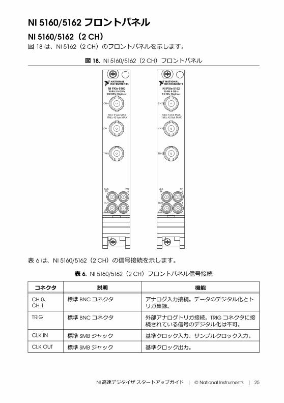
NI高速デジタイザ スタートアップガイド | © National Instruments | 25
NI 5160/5162 フロントパネルNI 5160/5162(2 CH)図 18は、NI 5162(2 CH)のフロントパネルを示します。
図 18. NI 5160/5162(2 CH)フロントパネル
表 6は、NI 5160/5162(2 CH)の信号接続を示します。
表 6. NI 5160/5162(2 CH)フロントパネル信号接続
コネクタ 説明 機能
CH 0、CH 1
標準 BNCコネクタ アナログ入接続。データのデジタル化とトリガ集録。
TRIG 標準 BNCコネクタ 外部アナログトリガ接続。TRIGコネクタに接続されている信号のデジタル化は不可。
CLK IN 標準 SMBジャック 基準クロック入、サンプルクロック入。
CLK OUT 標準 SMBジャック 基準クロック出。
CH 0
50 : 5 Vpk MAX1M : 42 Vpk MAX
CH 1
TRIG
CLKIN
PFI0
1OUT
NI PXIe-516010-Bit 2.5 GS/s
500 MHz Digitizer
CH 0
50 : 5 Vpk MAX1M : 42 Vpk MAX
CH 1
TRIG
CLKIN
PFI0
1OUT
NI PXIe-516210-Bit 5 GS/s
1.5 GHz Digitizer
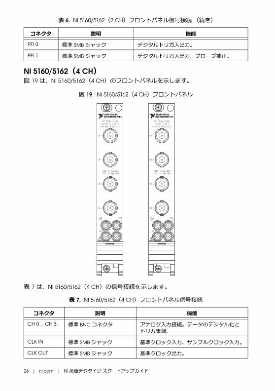
26 | ni.com | NI高速デジタイザ スタートアップガイド
NI 5160/5162(4 CH)図 19は、NI 5160/5162(4 CH)のフロントパネルを示します。
図 19. NI 5160/5162(4 CH)フロントパネル
表 7は、NI 5160/5162(4 CH)の信号接続を示します。
PFI 0 標準 SMBジャック デジタルトリガ入出。
PFI 1 標準 SMBジャック デジタルトリガ入出、プローブ補正。
表 7. NI 5160/5162(4 CH)フロントパネル信号接続
コネクタ 説明 機能
CH 0 ... CH 3 標準 BNCコネクタ アナログ入接続。データのデジタル化とトリガ集録。
CLK IN 標準 SMBジャック 基準クロック入、サンプルクロック入。
CLK OUT 標準 SMBジャック 基準クロック出。
表 6. NI 5160/5162(2 CH)フロントパネル信号接続 (続き)
コネクタ 説明 機能
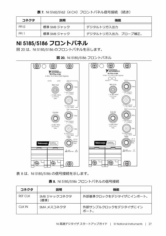
NI高速デジタイザ スタートアップガイド | © National Instruments | 27
NI 5185/5186 フロントパネル図 20は、NI 5185/5186のフロントパネルを示します。
図 20. NI 5185/5186 フロントパネル
表 8は、NI 5185/5186の信号接続を示します。
PFI 0 標準 SMBジャック デジタルトリガ入出
PFI 1 標準 SMBジャック デジタルトリガ入出、プローブ補正。
表 8. NI 5185/5186フロントパネルの信号接続
コネクタ 説明 機能
REF CLK SMBジャックコネクタ(標準)
外部基準クロックをデジタイザにインポート。
CLK IN SMAメスコネクタ 外部サンプルクロックをデジタイザにインポート。
表 7. NI 5160/5162(4 CH)フロントパネル信号接続 (続き)
コネクタ 説明 機能
5 GHz 12.5 GS/s 8-Bit DigitizerNI PXIe-5186
+16 dBm MAX(1.4 Vrms)
50Ω
±5 V MAX50Ω
50Ω
1MΩ
+9 dBm MAX(0.6 Vrms)
50Ω
50Ω
1MΩ
+16 dBm MAX(1.4 Vrms)
50Ω
±5 V MAX50Ω
50Ω
1MΩ
+9 dBm MAX(0.6 Vrms)
50Ω
50Ω
1MΩ
3 GHz 12.5 GS/s 8-Bit DigitizerNI PXIe-5185
1 Vpp measure
1 Vpp measure
10 Vpp measure
10 Vpp measure
± 1 V MAX
± 1 V MAX
± 42 V MAX
± 42 V MAX
1 Vpp measure
1 Vpp measure
10 Vpp measure
10 Vpp measure
± 1 V MAX
± 1 V MAX
± 42 V MAX
± 42 V MAX

28 | ni.com | NI高速デジタイザ スタートアップガイド
旧バージョン NI 5185/5186モジュール旧バージョンの NI 5185/5186では、50 Ωの入インピーダンスのみをサポートします。 NI 5185/5186のフロントパネルが上に表示されたフロントパネルと異なる場合、ご使用のデバイスは古い型番である可能性があります。 デバイスの製品番号で確認してください。• NI 5185モジュール(製品番号 199363x-0zL)および NI 5186モジュール(製品番
号 193537x-0zL)(x は文字、z は数字)は、50 Ω入インピーダンスのみをサポートします。
• NI 5185モジュール(製品番号 152962x-0zL)および NI 5186モジュール(製品番号 152961x-0zL)(x は文字、z は数字)は、50 Ωおよび 1 M Ωの入インピーダンスをサポートします。
CH 0 50 Ω、SMAメスコネクタ アナログ入接続。データのデジタル化とトリガ集録。
CH 0 1 MΩ、BNCメスコネクタ アナログ入接続。データのデジタル化とトリガ集録。
CH 1 50 Ω、SMAメスコネクタ アナログ入接続。データのデジタル化とトリガ集録。
CH 1 1 MΩ、BNCメスコネクタ アナログ入接続。データのデジタル化とトリガ集録。
TRIG SMAメスコネクタ 外部アナログトリガ接続。
表 8. NI 5185/5186フロントパネルの信号接続 (続き)
コネクタ 説明 機能

NI高速デジタイザ スタートアップガイド | © National Instruments | 29
NI 5622フロントパネル図 21は、NI PXIe-5622のフロントパネルを示します。
図 21. NI 5622フロントパネル
表 9は、NI 5622の信号接続を示します。
表 9. NI 5622 フロントパネルの信号接続
コネクタ 説明 機能
IF IN SMAメスコネクタ アナログ入接続。データのデジタル化とトリガ集録。
PFI 1 SMBジャックコネクタ デジタルトリガ接続。 (基準クロック入、サンプルクロック入、デジタルトリガ入出用の汎用 PFIライン)
CLK IN SMAメスコネクタ 外部基準クロックまたはサンプルクロックをデジタイザにインポート。
CLK OUT SMAジャックコネクタ デジタイザの基準クロックまたはサンプルクロックをエクスポート。
NI PXIe-562216-Bit IF Digitizer
ACCESS ACTIVE
PFI 1
IF IN
CLK IN
CLK OUT
TTL (+5 V MAX)
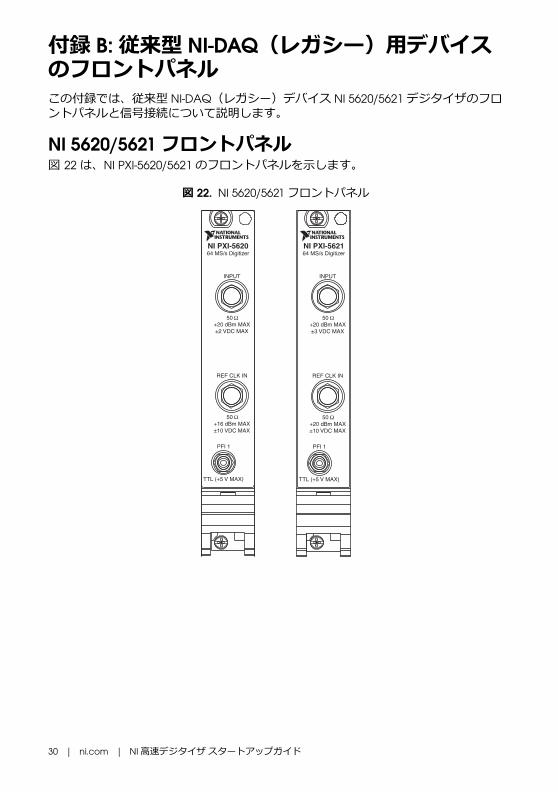
30 | ni.com | NI高速デジタイザ スタートアップガイド
付録 B: 従来型 NI-DAQ(レガシー)用デバイスのフロントパネルこの付録では、従来型 NI-DAQ(レガシー)デバイス NI 5620/5621デジタイザのフロントパネルと信号接続について説明します。
NI 5620/5621 フロントパネル図 22は、NI PXI-5620/5621のフロントパネルを示します。
図 22. NI 5620/5621 フロントパネル
NI PXI-562164 MS/s Digitizer
INPUT
50 +20 dBm MAX±3 VDC MAX
REF CLK IN
PFI 1
50 +20 dBm MAX±10 VDC MAX
TTL (+5 V MAX)
NI PXI-562064 MS/s Digitizer
INPUT
50 +20 dBm MAX±2 VDC MAX
REF CLK IN
PFI 1
50 +16 dBm MAX±10 VDC MAX
TTL (+5 V MAX)
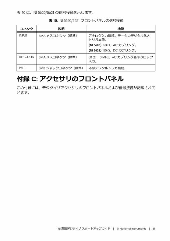
NI高速デジタイザ スタートアップガイド | © National Instruments | 31
表 10は、NI 5620/5621の信号接続を示します。
付録 C: アクセサリのフロントパネルこの付録には、デジタイザアクセサリのフロントパネルおよび信号接続が記載されています。
表 10. NI 5620/5621 フロントパネルの信号接続
コネクタ 説明 機能
INPUT SMAメスコネクタ(標準) アナログ入接続。データのデジタル化とトリガ集録。 (NI 5620)50 Ω、ACカプリング。(NI 5621)50 Ω、DCカプリング。
REF CLK IN SMAメスコネクタ(標準) 50 Ω、10 MHz、ACカプリング基準クロック入。
PFI 1 SMBジャックコネクタ(標準) 外部デジタルトリガ接続。
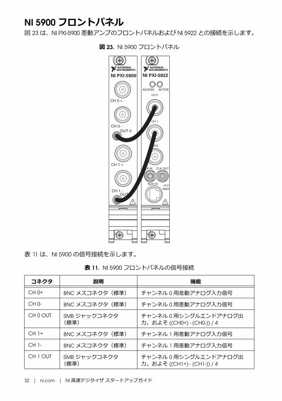
32 | ni.com | NI高速デジタイザ スタートアップガイド
NI 5900フロントパネル図 23は、NI PXI-5900差動アンプのフロントパネルおよび NI 5922との接続を示します。
図 23. NI 5900フロントパネル
表 11は、NI 5900の信号接続を示します。
表 11. NI 5900 フロントパネルの信号接続
コネクタ 説明 機能
CH 0+ BNCメスコネクタ(標準) チャンネル 0用差動アナログ入信号
CH 0- BNCメスコネクタ(標準) チャンネル 0用差動アナログ入信号
CH 0 OUT SMBジャックコネクタ(標準)
チャンネル 0用シングルエンドアナログ出。およそ ((CH0+) - (CH0-)) / 4
CH 1+ BNCメスコネクタ(標準) チャンネル 1用差動アナログ入信号
CH 1- BNCメスコネクタ(標準) チャンネル 1用差動アナログ入信号
CH 1 OUT SMBジャックコネクタ(標準)
チャンネル 0用シングルエンドアナログ出。およそ ((CH1+) - (CH1-)) / 4
NI PXI-5922
CH 0 +
CH 0 -OUT 0
NI PXI-5900
CH 1 +
CH 1 -OUT 1

NI高速デジタイザ スタートアップガイド | © National Instruments | 33
付録 D: トラブルシューティングPXI/PXI Expressシャーシの電源をれてもPXI/PXI Expressモジュールのフロントパネル ACCESS LEDが点灯しないPXI/PXI Expressシャーシの電源を投入してもデジタイザの ACCESS LEDが点灯しない場合は、PXI/PXI Expressの電源レール、ハードウェアデバイス、LEDのいずれかに問題がある可能性があります。
メモ LEDは、MAXでのデバイスの構成が完了しないと点灯しないことがあります。この問題のトラブルシューティングを開始する前に、MAXでこのデバイスが表示されるか確認してください。
この問題のトラブルシューティングは、以下の手順でってください。1. PXIシャーシの電源を切ります。2. PXIモジュールのフロントパネルへの信号接続をすべて取り外します。3. PXIモジュールをシャーシから取り外し、破損がないか確認します。 破損してい
るデバイスは使用しないでください。 4. 「5. ハードウェアを取り付ける」セクションの説明に従って、PXIモジュールを
再度取り付けます。5. PXIシャーシの電源を投入します。6. デバイスがMAXで表示されることを確認します。7. MAXでデバイスをリセットし、セルフテストを実します。 MAXでデバイスを
リセット、セルフテストする方法については、「6. MAXでの構成とテスト」セクションを参照してください。
8. 上記の手順をっても ACCESS LEDが点灯しない場合は、ナショナルインスツルメンツの技術サポート(ni.com/support)にお問い合わせください。
USBモジュールが接続されていても USBモジュールのバックパネル LEDが点灯しないUSBポートに接続してもデジタイザの LEDが点灯しない場合は、ソフトウェアのインストール、ハードウェアデバイス、LEDのいずれかに問題がある可能性があります。
メモ LEDは、MAXでのデバイスの構成が完了しないと点灯しないことがあります。この問題のトラブルシューティングを開始する前に、MAXでこのデバイスが表示されるか確認してください。
この問題のトラブルシューティングは、以下の手順でってください。1. USBデジタイザの電源プラグを抜きます。2. USBデジタイザのフロントパネルへの信号接続をすべて取り外します。

34 | ni.com | NI高速デジタイザ スタートアップガイド
3. 「5. ハードウェアを取り付ける」セクションの説明に従って、USBデバイスを再度取り付けます。
4. デバイスがMAXで表示されることを確認します。5. MAXでデバイスをリセットし、セルフテストを実します。 MAXでデバイスを
リセット、セルフテストする方法については、「6. MAXでの構成とテスト」セクションを参照してください。
6. 上記の手順をってもバックパネルの LEDが点灯しない場合は、ナショナルインスツルメンツの技術サポート(ni.com/support)にお問い合わせください。
デバイスがMAXで表示されないMAXにデバイスが表示されない場合は、以下の手順に従ってください。1. MAX構成ペーンで、デバイスとインタフェースをクリックして展開します。2. <F5>キーを押して、取り付けられているデバイスのリストを更新します。3. 上記の手順をってもデバイスが表示されない場合は、システムの電源を切り、
デバイスが適切に取り付けられているか確認した後、再度電源を投入します。4. それでもデバイスとインタフェースの下に表示されない場合は、ナショナルイン
スツルメンツの技術サポート(ni.com/support)にお問い合わせください。
デバイスがセルフテストで不合格になるMAXのセルフテストでは、デバイスリソースを確認します。 セルフテストでデバイスが不合格になった場合は、以下の手順に従ってください。1. コンピュータを再起動します。2. MAXを起動し、再度セルフテストを実します。 上記の手順をってもデバイ
スがセルフテストに合格しない場合は、手順 3に進んでください。3. NI-SCOPEをアンインストールし、再インストールします。4. それでもセルフテストに合格しない場合は、ナショナルインスツルメンツの技術
サポート(ni.com/support)にお問い合わせください。
過熱遮断エラー過熱(または過熱遮断)によりエラーが発生し、デバイスが停止した場合は、以下の方法に従ってデバイスを再度有効にします。1. デバイスが取り付けられているコンピュータまたはシャーシの電源を切ります。2. 「5. ハードウェアを取り付ける」セクションの手順を再度確認し、デバイスを効
果的に冷却するための手順を必要に応じて追加します。3. コンピュータまたはシャーシの電源を投入します。
メモ 過熱遮断エラーは、デバイスが適切な動作温度に戻り、また、正常にリセットされるまで発生し続けます。
NI高速デジタイザ スタートアップガイド | © National Instruments | 35
MXI接続時におけるパフォーマンスの問題MXIインタフェースによる PXIシャーシの制御時にパフォーマンスの低下や初期化に関する問題が発生する場合は、MXIのドキュメントを参照してMXIインタフェースが適切に設定されていることを確認します。また、 ソフトウェアの最適化が必要な場合もあります。• (MXI-3) 最適化するには、スタート→すべてのプログラム→ National Instruments
MXI-3→MXI-3 Optimizationを選択します。 このアプリケーションを実せずにMXI-3を使用すると、以下のようなエラーメッセージが表示されることがあります。– maximum amount of time exceeded(タイムアウトエラー)
– internal software error(内部ソフトウェアエラー)
ソフトウェアを最適化するアプリケーションがシステムにインストールされていない場合は、MXIソフトウェアメディアまたはキットに付属する National Instruments Driverメディアからインストールしてください。 MXI Optimization Applicationのインストール終了後に、コンピュータの再起動を必要とする場合があります。
• (MXI-4およびMXI-Express) 最適化は、ハードウェアによって自動的に実されます。
上記の手順をっても初期化やパフォーマンスに問題がある場合は、スタート→すべてのプログラム→ National Instruments MXIを選択してMXIのドキュメントを参照するか、ナショナルインスツルメンツの技術サポート(ni.com/support)にお問い合わせください。
同期をうための SMC対応デバイスの設定メモ SMC対応デバイスで同期(NI-TClkを含むすべての同期)をうには、以下の手順をう必要があります。 NI-TClkによる同期については、NI高速デジタイザヘルプ→プログラミング→リファレンス→ NI-TClk同期ヘルプを参照してください。
SMC対応デバイスで同期をう目的でトリガやクロックを共有する場合は、MAXで必要な項目を識別または構成する必要があります。
(PXIおよび PXI Expressモジュール) 以下の手順に従って、PXI Expressシステムコントローラを認識する必要があります。1. MAXのツリー構図で
a. PXIシステム→次のモデルとして識別を右クリックします。b. 一覧からコントローラを選択します。 たとえば、PCからMXIコントローラ
を使用する場合は、「外部 PC」を選択します。2. PXIシステムツリーを展開し、使用するシャーシの名前を右クリックします。
(PCIデバイス) 以下の手順に従って RTSIケーブルを構成する必要があります。1. PCIデバイス間を RTSIケーブルで接続して、トリガ /クロックを物理的に共有し
ます。

National Instrumentsの商標の詳細については、ni.com/trademarksに掲載されている「NI Trademarks and Logo Guidelines」 をご覧下さい。本文書中に記載されたその他の製品名および企業名は、それぞれの企業の商標または商号です。National Instrumentsの製品 /技術を保護する特許については、ソフトウェアで参照できる特許情報 (ヘルプ→特許情報 )、メディアに含まれている patents.txtファイル、または「National Instruments Patent Notice」(ni.com/patents)のうち、該当するリソースから参照してください。エンドユーザ使用許諾契約(EULA)に関する情報および他社製品の法的注意事項はご使用の NI製品の Readmeファイルにあります。ナショナルインスツルメンツの輸出関連法規遵守に対する方針について、また必要な HTSコード、ECCN、その他のインポート / エクスポートデータを取得する方法については、「輸出関連法規の遵守に関する情報」(ni.com/legal/export-compliance)を参照してください。© 2003–2013 National Instruments. All rights reserved.
2. MAXのツリー構図でa. NI-DAQmxデバイスを右クリックします。b. 新規 NI-DAQmxデバイスを作成→ RTSIケーブルを選択します。c. RTSIケーブルを右クリックし、RTSIケーブルに追加したいデバイスを選択し
ます。
付録 E: サポート情報技術サポートリソースの一覧は、ナショナルインスツルメンツのウェブサイトでご覧いただけます。 ni.com/supportでは、トラブルシューティングやアプリケーション開発のセルフヘルプリソースから、ナショナルインスツルメンツのアプリケーションエンジニアの Eメール /電話の連絡先まで、あらゆるリソースを参照することができます。
適合宣言(Doc)とは、その会社の自適合宣言を用いた、さまざまな欧州閣僚理事会指令への適合の宣言のことです。 この制度により、電磁両性(EMC)に対するユーザ保護や製品の安全性に関する情報が提供されます。 ご使用の製品の適合宣言は、ni.com/certification(英語)から入手できます。 ご使用の製品でキャリブレーションがサポートされている場合、ni.com/calibrationからその製品のCalibration Certificate(英語)を入手してご利用になることもできます。
ナショナルインスツルメンツでは、米国本社(11500 North Mopac Expressway, Austin, Texas, 78759-3504)および各国の現地オフィスにてお客様にサポート対応しています。 日本国内でのサポートについては、ni.com/supportでサポートリクエストを作成するか、0120-527196(フリーダイヤル)または 03-5472-2970(大代表)までお電話ください。日本国外でのサポートについては、ni.com/niglobal(英語)の「Worldwide Offices」セクションから、お問い合わせ先、サポート電話番号、電子メールアドレス、現在実施中のイベントに関する最新情報を提供する各支社のウェブサイトにアクセスできます。
Related Documents