TP-P572-V-01 Dec 2019 U.S. DEPARTMENT OF TRANSPORTATION NATIONAL HIGHWAY TRAFFIC SAFETY ADMINISTRATION LABORATORY TEST PROCEDURE FOR Part 572, SUBPART V PERFORMANCE CALIBRATION REQUIREMENTS ENFORCEMENT Office of Vehicle Safety Compliance Mail Code: NEF-240 1200 New Jersey Ave. SE Washington, DC 20590

Welcome message from author
This document is posted to help you gain knowledge. Please leave a comment to let me know what you think about it! Share it to your friends and learn new things together.
Transcript

TP-P572-V-01 Dec 2019
U.S. DEPARTMENT OF TRANSPORTATION
NATIONAL HIGHWAY TRAFFIC SAFETY ADMINISTRATION
LABORATORY TEST PROCEDURE
FOR
Part 572, SUBPART V PERFORMANCE CALIBRATION REQUIREMENTS
ENFORCEMENT Office of Vehicle Safety
Compliance Mail Code: NEF-240 1200 New Jersey Ave. SE
Washington, DC 20590

TP-P572-V-01
-ii-
TABLE OF CONTENTS
1. PURPOSE AND APPLICATION ......................................................................................... 1
2. GENERAL REQUIREMENTS ..............................................................................................1
3. SECURITY ............................................................................................................................ 1
4. GOOD HOUSEKEEPING. .................................................................................................... 2
5. TEST SCHEDULING AND MONITORING ....................................................................... 2
6. TEST DATA DISPOSITION ................................................................................................ 2
7. GOVERNMENT FURNISHED PROPERTY ....................................................................... 2
8. CALIBRATION AND TEST INSTRUMENTATION ......................................................... 3
9. PHOTOGRAPHIC DOCUMENTATION. ............................................................................ 4
10. PRETEST REQUIREMENTTS ............................................................................................ 4
11. CALIBRATION TEST EXECUTION ...................................................................................7
12 POST TEST REQUIREMENTS ............................................................................................7
13. REPORTS .............................................................................................................................. 7
14. CHECK SHEETS .................................................................................................................. 8 V1 EXTERNAL MEASUREMENTS .......................................................................... 8 V2 HEAD DROP TEST ............................................................................................. 11 V3 NECK FLEXION TEST ....................................................................................... 17 V4 SHOULDER IMPACT TEST. ............................................................................... 39 V5 THORAX – W/ARM IMPACT TEST ..................................................................46 V6 THORAX – W/O ARM IMPACT TEST ..............................................................51 V7 ABDOMEN IMPACT TEST ................................................................................ 55 V8 PELVIS PLUG QUASI-STATIC TESTS .............................................................59 V9 PELVIS ACETABULUM IMPACT TEST. .......................................................... 61 V10 PELVIS ILIAC IMPACT TEST ............................................................................66
List of Figures ................................................................................................................................ iii List of Tables .................................................................................................................................. v
ATTACHMENT 1-Attachment of Thoracic and Abdominal Pads ATTACHMENT 2-Iliac Probe Face ATTACHMENT 3-Iliac Alignment Tool

TP-P572-V-01
-iii-
List of Figures
Figure 1. Seated Position of SID-IIsD for taking external dimensions .......................................... 8 Figure 2. Threaded cylindrical tool for SID-IIsD ........................................................................... 9 Figure 3. Threaded cylindrical tool installed at the acetabulum ..................................................... 9 Figure 4. Installing head accelerometers to mount ....................................................................... 11 Figure 5. Installing accelerometers in head ................................................................................. 11 Figure 6. Head reassembly with hex rod installed for routing suspension cable ......................... 12 Figure 7. Securing the suspension cable to the top of the head ................................................... 12 Figure 8. Routing the suspension cables for head drop tests ....................................................... 13 Figure 9. Adjusting the D-plane to 35° ........................................................................................ 14 Figure 10. Leveling the head in the fore-aft direction ................................................................. 14 Figure 11. Raising head to proper drop height.............................................................................. 15 Figure 12a. Center bracket, front and rear disks of head form ..................................................... 18 Figure 12b. Head potentiometer ................................................................................................... 18 Figure 13. Attaching the pot shaft collar to the head pot ............................................................... 19 Figure 14. Assembling front head form disk to rear disk ..............................................................19 Figure 15. Attaching the pot extension shaft to the pot shaft collar ..............................................20 Figure 16. Attaching the retaining collar to the pot extension shaft ..............................................20 Figure 17. Removing the nodding joint assembly ......................................................................... 22 Figure 18. Install bib simulator ..................................................................................................... 23 Figure 19. Assemble molded neck to neck mounting plate ...........................................................23 Figure 20. Install lower neck bushing, washer, and hex nut unto neck cable ................................23 Figure 21. Torque hex nut on neck cable to 10-12 in-lbs .............................................................. 24 Figure 22. Reinstall neck nodding joint assembly .........................................................................24 Figure 23 Install potentiometer brackets (left side neck test illustrated ....................................... 25 Figure 24. Install brass nodding joint washers. ............................................................................. 26 Figure 25 Install the upper neck load cell .................................................................................... 26 Figure 26. Align brass nodding joint washers with holes ............................................................. 27 Figure 27. Insert and install neck pivot pin. .................................................................................. 27 Figure 28. Install upper neck load cell to head form ..................................................................... 28 Figure 29. Install the inner potentiometer rod assembly ................................................................29 Figure 30. Install the outer potentiometer rod assembly ................................................................ 29 Figure 31. Assembling chest rotary potentiometer and potentiometer housing assembly ............ 30 Figure 32. Install potentiometer on inner pot rod onto inner potentiometer pivot bracket ............31 Figure 33. Tighten set screws for inner potentiometer pivot bracket ............................................31 Figure 34. Final configuration of head form attached to neck with dummy head ........................ 32 Figure 35. Pendulum configuration for a left side neck test ..........................................................33 Figure 36. Attachment of inner and outer pot rod assemblies to neck mounting plate ................ 34 Figure 37. Pendulum configuration for a right side neck test ........................................................35 Figure 38. Correct outer and inner pot/rod assembly locations for a right-side test ......................36 Figure 39. Angle measurements with the head form setup ........................................................... 37

TP-P572-V-01
-iv-
List of Figures (cont’d)
Figure 40. Certification bench seat specifications ........................................................................ 39 Figure 41. Shoulder impact test configuration for SID-IIsD ........................................................ 40 Figure 42. Impact probe and dummy seating position ................................................................. 41 Figure 43. SID-IIsD leg positioning ............................................................................................. 42 Figure 44. SID-IIsD feet positioning ........................................................................................... 42 Figure 45. Adjusting the SID-IIsD dummy in the lateral direction .............................................. 43 Figure 46. Adjusting the SID-IIsD in the fore/aft plane .............................................................. 44 Figure 47. Aligning the upper and lower neck brackets flush for testing .................................... 46 Figure 48. Thorax with arm impact test configuration for SID-IIsD ............................................47 Figure 49. Impact probe position for the SID-IIsD thorax with arm qualification test ................48 Figure 50. Thorax without arm impact test configuration for SID-IIsD ....................................... 52 Figure 51. Impact probe position for the SID-IIsD thorax w/o arm test .......................................53 Figure 52. Abdomen impact test configuration for SID-IIsD .......................................................56 Figure 53. Impact probe position for the SID-IIsD abdomen test .................................................57 Figure 54. Pelvis plug quasi static test ......................................................................................... 59 Figure 55. Corridors for pelvis plug quasi-static test .................................................................. 60 Figure 56 Maximum force and displacement corridors for pelvis plug quasi-static test .............. 60 Figure 57. Pelvis acetabulum test configuration for SID-IIsD ....................................................... 61 Figure 58. Impact probe position for the SID-IIsD pelvis acetabulum test ....................................62 Figure 59. SID-IIsD leg and back positioning for pelvis acetabulum test ...................................... 63 Figure 60. Adjusting the SID-IIsD in the fore/aft plane for pelvis acetabulum test .....................64 Figure 61. Setup of the dummy for the pelvis iliac test .................................................................. 67 Figure 62 Using masking tape to seat the dummy upright .......................................................... 68 Figure 63. Adjusting the SID-IIsD in the fore/aft plane for the pelvis iliac test ........................... 68 Figure 64. Adjusting the SID-IIsD in the lateral direction for the pelvis iliac test ....................... 69 Figure 65. Iliac alignment tool ..................................................................................................... 69 Figure 66. Iliac probe with alignment tool inserted ...................................................................... 70 Figure 67. Iliac alignment tool inserted into iliac load cell ........................................................... 70 Figure 68. Adjusting the pelvic position for inserting the alignment tool .................................... 71 Figure 69. Assuring smooth motion of the alignment tool shaft within the probe .......................71
TP-P572-V-01
-v-
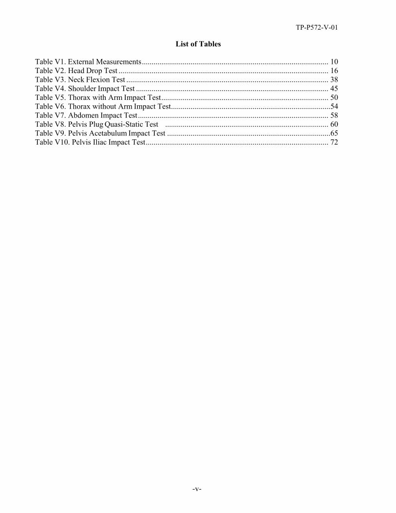
List of Tables
Table V1. External Measurements ................................................................................................ 10 Table V2. Head Drop Test ............................................................................................................ 16 Table V3. Neck Flexion Test ........................................................................................................ 38 Table V4. Shoulder Impact Test ................................................................................................... 45 Table V5. Thorax with Arm Impact Test ...................................................................................... 50 Table V6. Thorax without Arm Impact Test .................................................................................. 54 Table V7. Abdomen Impact Test .................................................................................................. 58 Table V8. Pelvis Plug Quasi-Static Test .................................................................................... 60 Table V9. Pelvis Acetabulum Impact Test .................................................................................... 65 Table V10. Pelvis Iliac Impact Test .............................................................................................. 72

-1-
TP-P572-V-01
1. PURPOSE AND APPLICATION
The purpose of this laboratory procedure is to provide dummy users (independent testing laboratories under contract with the Office of Vehicle Safety Compliance) with standard test procedures for performing receiving-inspection and performance calibration tests on the Part 572, Subpart V dummy so that repetitive and correlative test results can be obtained. The following tests have been developed to establish a uniform calibration procedure for all users as the means of verifying the performance of the dummy.
A. EXTERNAL MEASUREMENTS
B. HEAD DROP TEST (572.192)
C. NECK FLEXION TEST (572.193)
D. SHOULDER IMPACT TEST (572.194)
E. THORAX w/ARM IMPACT TEST (572.195)
F. THORAX w/o ARM IMPACT TESTS (572.196)
G. ABDOMEN IMPACT TEST (572.197)
H. PELVIS PLUG QUASI-STATIC TEST
I. PELVIS ACETABULUM IMPACT TEST (572.198)
J. PELVIS ILIAC IMPACT TEST (572.199)
2. GENERAL REQUIREMENTS
A properly configured Part 572, Subpart V SIDIIs-D, 5th percentile female side impact dummy must be tested to the calibration requirements stated herein prior to and after being used in a compliance crash test. Contractors may use “passing” post test calibration data to indicate the pre-test condition of a test dummy used in consecutive crash tests occurring less than 90 days apart. Otherwise, a full pretest calibration must be performed.
3. SECURITY
All NHTSA test dummies delivered to the contract laboratory as Government Furnished Property (GFP) will be stored in a safe and secure area such as the dummy calibration laboratory. The contractor is financially responsible for any acts of theft and/or vandalism which occur during the storage of GFP. Any security problems shall be reported by telephone to the Industrial Property Manager (IPM), Office of Contracts and Procurement, within two working days after the incident. A letter containing specific details of the security problem will be sent to the IPM with copy to the Contract Officer’s Representative (COR) within 48 hours.
-2-
TP-P572-V-01
3. SECURITY….Continued
The contractor is responsible for maintaining the NHTSA test dummies in good working order, and shall protect and segregate the data that evolves from conducting dummy calibration tests before and after each vehicle crash usage.
No information concerning the dummy calibration data shall be released to anyone except the COR, unless specifically authorized by the COR or the COR's Division Chief.
NOTE: No individuals, other than contractor personnel directly involved in the dummy calibration test program, shall be allowed to witness dummy calibration tests unless specifically authorized by the COR.
4. GOOD HOUSEKEEPING
Contractors shall maintain the entire dummy calibration laboratory, test fixtures, and instrumentation in a neat, clean, and painted condition with test instruments arranged in an orderly manner consistent with good test laboratory housekeeping practices.
5. TEST SCHEDULING AND MONITORING
The Part 572, Subpart V dummies are being calibrated as test tools to be used in a vehicle test to determine compliance with the requirements of FMVSS 214. The schedule for these performance calibration tests must be correlated with that of the vehicle tests. Upon request, all testing shall be coordinated to allow monitoring by the COR.
6. TEST DATA DISPOSITION
The contractor shall make all dummy calibration data available to the COR for review and analysis as required. Calibration test data for each dummy will be sent to the COR with each test report in the format indicated in this test procedure.
All backup data sheets, strip charts, recordings, plots, technician’s notes, etc. shall be either sent to the COR or destroyed at the conclusion of each delivery order, purchase order, etc.
7. GOVERNMENT FURNISHED PROPERTY (GFP)
Part 572 test dummies will be furnished to the contract laboratory by the OVSC. The dummies shall be stored in an upright sitting position with the weight supported by the internal structure of the pelvis. The dummies head shall be held upright without supporting the weight of the dummy by using an eyebolt that can be secured in the top of the head. These dummies shall be stored in a secured room that is kept between 55ºF and 85ºF. The contractor will check dummy components for damage after each crash test and complete a dummy damage checklist that will be included with the posttest dummy calibration. The COR will be kept informed of the dummies condition in order that replacement parts can be provided. The contractor shall calibrate the dummies before and verify the calibration after every crash test.

-3-
TP-P572-V-01
8. CALIBRATION AND TEST INSTRUMENTATION
Before the contractor initiates the dummy performance calibration test program, a test instrumentation calibration system must be implemented and maintained in accordance with established calibration practices. The calibration system shall be set up and maintained as follows:
A. Standards for calibrating the measuring and test equipment shall be stored and used under appropriate environmental conditions to assure their accuracy and stability.
B. All measuring instruments and standards shall be calibrated by the contractor, or a commercial facility, against a higher order standard at periodic intervals not exceeding 12 months for instruments and 12 months for calibration standards. Records, showing the calibration traceability to the National Institute of Standards and Technology (NIST), shall be maintained for all measuring and test equipment.
C. All measuring and test equipment and measuring standards shall be labeled with the following information:
(1) Date of calibration
(2) Date of next scheduled calibration
(3) Name of the technician who calibrated the equipment
D. The contractor shall provide a written calibration procedure that includes, as a minimum, the following information for all measurement and test equipment.
(1) Type of equipment, manufacturer, model number, etc.
(2) Measurement range
(3) Accuracy
(4) Calibration interval
(5) Type of standard used to calibrate the equipment (calibration traceability of the standard must be evident)
(6) The actual procedures and forms used to perform calibrations.
E. The contractor shall keep records of calibrations for all test instrumentation in a manner that assures the maintenance of established calibration schedules. All such records shall be readily available for inspection when requested by the COR. The calibration system will need the written acceptance of the COR before testing begins.
F. Test equipment shall receive a calibration check immediately prior to and after each test. This check shall be recorded by the test technician(s) and submitted with the final report.
G. Anthropomorphic test devices shall be calibrated before and after each test. These calibrations shall be submitted with the final report.

TP-P572-V-01
-4-
9. PHOTOGRAPHIC DOCUMENTATION
Provide digital still photographs showing any damage that occurred to the test dummy as a result of the crash test. Provide copies of the photographs in the draft test report.
10. PRETEST REQUIREMENTS
10.1 HEAD DROP TEST FIXTURE (572.192(a) & 572.112(a)) A test fixture configured in accordance with the specifications contained in the figure below shall be used to conduct the head drop tests.

TP-P572-V-01
-5-
10. PRETEST REQUIREMENTS…Continued
10.2 PART 572 PENDULUM TEST FIXTURE (572.193(b)(2), 572.33)
A pendulum configured in accordance with the specifications contained in the figure below shall be used to conduct the neck and lumbar flexion tests.
TP-P572-V-01
-6-
10. PRETEST REQUIREMENTS…Continued
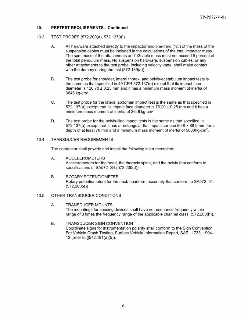
10.3 TEST PROBES (572.200(a), 572.137(a))
A. All hardware attached directly to the impactor and one-third (1/3) of the mass of the suspension cables must be included in the calculations of the total impactor mass. The sum mass of the attachments and1/3cable mass must not exceed 5 percent of the total pendulum mass. No suspension hardware, suspension cables, or any other attachments to the test probe, including velocity vane, shall make contact with the dummy during the test (572.189(a)).
B. The test probe for shoulder, lateral thorax, and pelvis-acetabulum impact tests is the same as that specified in 49 CFR 572.137(a) except that its impact face diameter is 120.70 ± 0.25 mm and it has a minimum mass moment of inertia of 3646 kg-cm2.
C. The test probe for the lateral abdomen impact test is the same as that specified in 572.137(a) except that its impact face diameter is 76.20 ± 0.25 mm and it has a minimum mass moment of inertia of 3646 kg-cm2.
D. The test probe for the pelvis-iliac impact tests is the same as that specified in 572.137(a) except that it has a rectangular flat impact surface 50.8 × 88.9 mm for a depth of at least 76 mm and a minimum mass moment of inertia of 5000 kg-cm2.
10.4 TRANSDUCER REQUIREMENTS
The contractor shall provide and install the following instrumentation;
A. ACCELEROMETERS Accelerometers for the head, the thoracic spine, and the pelvis that conform to specifications of SA572–S4.(572.200(d))
B. ROTARY POTENTIOMETER Rotary potentiometers for the neck-headform assembly that conform to SA572–51. (572.200(e))
10.5 OTHER TRANSDUCER CONDITIONS
A. TRANSDUCER MOUNTS The mountings for sensing devices shall have no resonance frequency within range of 3 times the frequency range of the applicable channel class. (572.200(h)).
B. TRANSDUCER SIGN CONVENTION Coordinate signs for instrumentation polarity shall conform to the Sign Convention For Vehicle Crash Testing, Surface Vehicle Information Report, SAE J1733, 1994– 12 (refer to §572.191(a)(5)).
TP-P572-V-01
-7-
10. PRETEST REQUIREMENTS….Continued
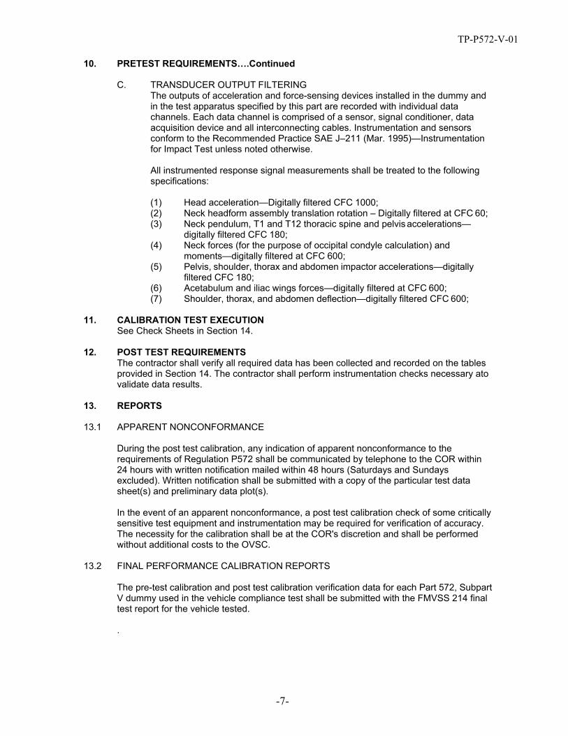
C. TRANSDUCER OUTPUT FILTERING The outputs of acceleration and force-sensing devices installed in the dummy and in the test apparatus specified by this part are recorded with individual data channels. Each data channel is comprised of a sensor, signal conditioner, data acquisition device and all interconnecting cables. Instrumentation and sensors conform to the Recommended Practice SAE J–211 (Mar. 1995)—Instrumentation for Impact Test unless noted otherwise.
All instrumented response signal measurements shall be treated to the following specifications:
(1) Head acceleration—Digitally filtered CFC 1000; (2) Neck headform assembly translation rotation – Digitally filtered at CFC 60; (3) Neck pendulum, T1 and T12 thoracic spine and pelvis accelerations—
digitally filtered CFC 180; (4) Neck forces (for the purpose of occipital condyle calculation) and
moments—digitally filtered at CFC 600; (5) Pelvis, shoulder, thorax and abdomen impactor accelerations—digitally
filtered CFC 180; (6) Acetabulum and iliac wings forces—digitally filtered at CFC 600; (7) Shoulder, thorax, and abdomen deflection—digitally filtered CFC 600;
11. CALIBRATION TEST EXECUTION See Check Sheets in Section 14.
12. POST TEST REQUIREMENTS The contractor shall verify all required data has been collected and recorded on the tables provided in Section 14. The contractor shall perform instrumentation checks necessary ato validate data results.
13. REPORTS
13.1 APPARENT NONCONFORMANCE
During the post test calibration, any indication of apparent nonconformance to the requirements of Regulation P572 shall be communicated by telephone to the COR within 24 hours with written notification mailed within 48 hours (Saturdays and Sundays excluded). Written notification shall be submitted with a copy of the particular test data sheet(s) and preliminary data plot(s).
In the event of an apparent nonconformance, a post test calibration check of some critically sensitive test equipment and instrumentation may be required for verification of accuracy. The necessity for the calibration shall be at the COR's discretion and shall be performed without additional costs to the OVSC.
13.2 FINAL PERFORMANCE CALIBRATION REPORTS
The pre-test calibration and post test calibration verification data for each Part 572, Subpart V dummy used in the vehicle compliance test shall be submitted with the FMVSS 214 final test report for the vehicle tested.
.

TP-P572-V-01
-8-
14. CHECK SHEETS
CHECK SHEET NO. V1 EXTERNAL MEASUREMENTS
Dummy Serial No. Technician
Test Date
1 With the dummy’s jacket in place, seat the dummy on a flat, rigid, smooth, clean, dry, horizontal surface. The seating surface must be at least 406 mm (16-in) wide and 406-mm (16-in) deep, with a vertical section at least 406 mm (16 in) wide and 914-mm (36 in) high attached to the rear of the seating fixture. The dummy’s midsagittal plane is vertical and centered on the test surface.
2 Seat the dummy in the test fixture so that the torso is against the vertical surface of the fixture (Figure 1).
Figure 1. Seated Position of SID-IIsD for taking external measurements (Dummy configured for right-side impact)
3 Take the following measurements and record on Table V1. Verify that each measurement meets the specification by indicating “Pass” or “Fail” in the far right column.
4 Chest Circumference (Y): With the jacket on, using a tape measure positioned 114 mm (4.5”) below the top surface of the non-struck side shoulder, measure the chest circumference.
5 Remove the chest jacket. Position the dummy against the vertical back plate so that dummy is in contact with the surface. Level the top surface of the top rib guide laterally. Extend the dummy’s neck so that the base of the skull is level side-to-side, within 0.5 degrees. The rear surface of the skull cap should be 43 +/- 3 mm (1.70 +/- 0.10 in) from the vertical surface of the test fixture (parameter H). A 43-mm wide block mounted to the vertical surface of the seat behind the head will aid in this process. In addition, a strap or bungee cord may be placed around the forehead of the dummy to stabilize the head in this position.

TP-P572-V-01
-9-
CHECK SHEET NO. V1 (Continued) EXTERNAL MEASUREMENTS
6 Position the dummy’s H-point (both left and right sides) so it is 84 +/- 5 mm (3.30 +/- 0.20 in) above the horizontal seating surface and 146 +/- 5 mm (5.75 +/- 0.20 in) forward of the rear vertical surface of the fixture (parameters C and D, respectively). A threaded cylindrical tool, as illustrated in Figure 2, which can be screwed into the acetabulum load cell replacement (Figure 3) in place of the ¼-20 x 5/8” FHCS, will aid this process.
Figure 2. Threaded cylindrical tool 5.625 in
Figure 3. Threaded cylindrical tool installed at acetabulum
7 Sitting Height (A): With the head positioned as indicated in step 6, measure the distance from the seat horizontal surface to a level placed on top of the head.
8 Shoulder Pivot Height (B): Level the shoulder load cell structural replacement. Measure from the centerline of the shoulder yoke assembly to the seat horizontal surface. For ease of measurement, it is recommended to measure from the top of the load cell replacement to the horizontal seat surface and adjust this value by ½ the height of the structural load cell replacement.
9 Shoulder Pivot From Backline (E): Level the shoulder load cell structural replacement. Measure from the centerline of the shoulder yoke assembly to the seat vertical surface (seatback). For ease of measurement, it is recommended to measure from the front of the load cell replacement to the seat back and adjust this value by ½ the width of the structural load cell replacement.
10 Thigh Clearance (F): Measure from the horizontal seat surface to the highest point on the thigh flesh. A level placed laterally across both thighs at the highest point will aid in this process
11 Head Breadth (G) Measure the widest part of the head. 12 Head Depth (I) Measure from the back of the head to the forehead. 13 Head Circumference (J) Measure at the point used for dimension “I”. 14 Buttock to Knee Length (K): Measure from the rear surface of the buttock to the front
edge of the knee in line with the knee pivot and hip pivot. Use of a vertically positioned level will aid in this measurement.
15 Popliteal Height (L): Position the front edge of the lower leg vertically. Level the bottom of the feet. Measure from the bottom of the feet to the seat horizontal surface.

TP-P572-V-01
-10-
CHECK SHEET NO. V1 (Continued) EXTERNAL MEASUREMENTS
16 Knee Pivot to Floor Height (M): Position the front edge of the lower leg vertically. Level the bottom of the feet. Measure from the bottom of the feet to the knee pivot.
17 Buttock Popliteal Length (N): Place a ½” diameter rod behind the knee and pull it forward against the back of the knee joint. Measure from the (anterior) edge of the rod nearest the knee joint to the rear surface of buttock.
18 Foot Length (P): Measure the maximum foot length from heel to toe. 19 Hip Breadth (Q) Measure the widest part of the hip with both pelvic plugs installed. 20 Arm Length (R) Measure from the top of the shoulder to the bottom of the elbow. 21 Knee Joint to Seat Back (S) Measure from the center of the knee joint to the seat back.
Use of a horizontally positioned level will aid in this measurement. 22 Foot Width (W): Measure the maximum foot width from left to right. 23 Chest Depth (O): Push the thorax against the seat back. At a distance of 381 mm (15”)
above the seat surface (on the rib guide between the first and second ribs), measure the horizontal distance from this point to the seatback.
24 Shoulder Width (V): With only one arm installed (left or right), measure the distance between the outside surface of the shoulder plug and the rib mounting bracket on the non- struck side.
25 Waist Circumference (Z): Use a tape measure to measure the circumference of the waist within 6 mm (0.25”) of the topmost portion of the pelvis flesh, avoiding the zipper closure.
Table V1. External Measurements
No.
Name
Spec. (mm)
Result
Pass/ Fail
A Sitting Height 772 – 788 B Shoulder Pivot Height 437 – 453 C H-point Height 79 – 89 D H-point from seatback 141 – 151 E Shoulder Pivot from Backline 97 – 107 F Thigh Clearance 119 – 135 G Head Breadth 140 – 148 H Head Back from Backline 40 – 46 I Head Depth 178 – 188 J Head Circumference 541 – 551 K Buttock to Knee Length 514 – 540 L Popliteal Height 343 – 369 M Knee Pivot to floor height 392 – 409 N Buttock Popliteal Length 416 – 442 O Chest Depth w/o jacket 195 – 211 P Foot Length 216 – 232 Q Hip Breadth (w/pelvic plugs) 313 – 323 R Arm Length 249 – 259 S Knee Joint to seatback 477 – 493 V Shoulder Width 341 – 357 W Foot Width 78 – 94 Y Chest Circumference w/jacket 851 – 881 Z Waist Circumference 761 - 791
Signature Completion Date

TP-P572-V-01
CHECK SHEET NO. V2 HEAD DROP TEST (S572.192)
-11-
Dummy Serial No. Technician
Test Date
Pretest Preparation 1 Inspect the head skin for cracks, tears or other damage. Replace the skin if
necessary. 2 Remove the skullcap from the head assembly (Part No. 180-1000) and
inspect for defects. If defects are present, repair or replace.
Note: If the damage results from the vehicle crash test in which the dummy was an occupant, the damaged area is to be documented with photography and the post test calibration verification testing completed before any replacement or repairs are made.
3 Soak the head assembly in a controlled environment at a temperature and relative humidity indicated in Table V2 for at least four hours prior to a test. Record the length of time for the soak and the maximum and minimum temperature and humidity in Table V2. Verify that each measurement meets specification by indicating “Pass” or “Fail” in the far right column.
4 Install the 3 accelerometers onto the mount (Figure 4) assuring that all axes are oriented properly.
5 Install the accelerometer mount into the head (Figure 5) and tighten all screws.
left side of head
front of head
Figure 4. Installing head accelerometers to mount
Z
Y
X is forward (not shown)
Figure 5. Installing accelerometers in head

TP-P572-V-01
CHECK SHEET NO. V2 HEAD DROP TEST (S572.192)
-12-
6 Replace the skullcap, taking care not to damage accelerometer wiring protruding from the head (Figure 6).
7 When replacing the skullcap, use the standard skullcap bolts for all but the bottom left (for left side impacts) or bottom right (for right side impacts) bolts. Instead, insert a threaded 4.2 cm long (1.3 cm of the 4.2 cm is threaded) hex rod so that it protrudes from the skullcap. Tighten the rod into the threaded hole with a wrench. This rod will be used to route the cabling which holds the head assembly for test.
8 Install the upper neck structural replacement to the base of the head. 9 Clean the headskin with isopropyl alcohol and allow it to dry thoroughly.
threadedhex rod
upper neck structural replacement
Figure 6. Head reassembly with hex rod installed for routing suspension cable
10 Install the threaded Teflon cylinder with suspension cable attached into the top of the head (Figure 7).
Figure 7. Securing the suspension cable to the top of the head

TP-P572-V-01
CHECK SHEET NO. V2 (Continued) HEAD DROP TEST (S572.192)
-13-
11 Suspend the head assembly using the head suspension cables (Figure 8). Route the suspension cable around the protruding hex bolt, and between the lips.
to skullcap hex bolt
to lips
around hex bolt
to lips
to top head
Figure 8. Routing the suspension cables for head drop tests (left-side impact)

TP-P572-V-01
CHECK SHEET NO. V2 (Continued) HEAD DROP TEST (S572.192)
-14-
12 Adjust the head so that the skull base/D-plane is 35° ± 1° from the vertical (Figure 9).
35°
Figure 9. Adjusting the D-plane to 35° (left side impact shown)
13 Level the head so that it is horizontal in the fore-aft direction (Figure 10).
Figure 10. Leveling the head in the fore-aft direction

TP-P572-V-01
CHECK SHEET NO. V2 (Continued) HEAD DROP TEST (S572.192)
-15-
14 Raise the head assembly so that it is 200mm ± 1 (7.87in. ± 0.04) from the impact point to the lowest point on the head (Figure 10).
15 Clean the impact surface with isopropyl alcohol.
200 mm
Figure 11. Raising head to proper drop height
Conduct the Test, Collect Data and Verify Performance 16 Record the room temperature and humidity in Table V2. Verify that the temperature and
relative humidity meets specification by indicating “Pass” or “Fail” in the far right column. 17 Release the head assembly so that it falls freely to the impact surface. 18 Record head accelerations and filter using a Channel Class 1000 phaseless filter. 19 Time zero is defined as the time of contact between the head and the impact
surface. All channels should be at a zero level at this point. 20 Plot the Head X acceleration and resultant acceleration data traces. 21 Calculate the resultant head acceleration using the formula:
ares = [(ax )2 + (ay )2 + (a 2z ) ]1/2 22 Record the peak head resultant acceleration and peak head X acceleration in Table V2.
Verify that each measurement meets specification by indicating “Pass” or “Fail” in the far right column.
23 If the test results are not within specification, wait at least 2 hours, conduct another head drop test.
24 Record and report the results of each additional test in a separate table.

TP-P572-V-01
CHECK SHEET NO. V2 (Continued) HEAD DROP TEST (S572.192)
-16-
Table V2. Head Drop Test
Tested Parameter
Units
Specification
Result Pass/ Fail
Head Assembly Soak Time Minutes 240
Temperature - During Soak
Max °C 18.9 to 25.6
Min °C
Humidity - During Soak
Max % 10.0 to 70.0
Min %
Temperature – During test °C 18.9 to 25.6
Humidity – During test % 10.0 to 70.0 Peak Head Resultant Acceleration g’s 115 to137 Peak Head X Acceleration g’s <15 Uni-modal (Oscillation) Yes/No <15%
Signature Completion Date
TP-P572-V-01
-17-
CHECK SHEET NO. V3 NECK FLEXION TEST (S572.193)
Dummy Serial No. Technician
Test Date
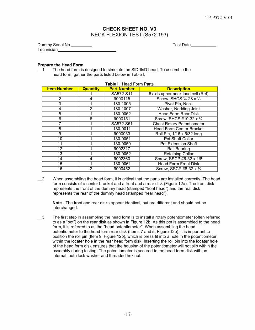
Prepare the Head Form 1 The head form is designed to simulate the SID-IIsD head. To assemble the
head form, gather the parts listed below in Table I.
Table I. Head Form Parts Item Number Quantity Part Number Description
1 1 SA572-S11 6 axis upper neck load cell (Ref) 2 4 9000115 Screw, SHCS ¼-28 x ½ 3 1 180-1005 Pivot Pin, Neck 4 2 180-1007 Washer, Nodding Joint 5 1 180-9062 Head Form Rear Disk 6 6 9000151 Screw, SHCS #10-32 x ¾ 7 1 SA572-S51 Chest Rotary Potentiometer 8 1 180-9011 Head Form Center Bracket 9 1 9000033 Roll Pin, 1/16 x 5/32 long 10 1 180-9051 Pot Shaft Collar 11 1 180-9050 Pot Extension Shaft 12 1 9002317 Ball Bearing 13 1 180-9052 Retaining Collar 14 4 9002360 Screw, SSCP #6-32 x 1/8 15 1 180-9061 Head Form Front Disk 16 2 9000452 Screw, SSCP #8-32 x ¼
2 When assembling the head form, it is critical that the parts are installed correctly. The head form consists of a center bracket and a front and a rear disk (Figure 12a). The front disk represents the front of the dummy head (stamped “front head”) and the rear disk represents the rear of the dummy head (stamped “rear head”).
Note - The front and rear disks appear identical, but are different and should not be interchanged.
3 The first step in assembling the head form is to install a rotary potentiometer (often referred to as a “pot”) on the rear disk as shown in Figure 12b. As this pot is assembled to the head form, it is referred to as the "head potentiometer". When assembling the head potentiometer to the head form rear disk (Items 7 and 5, Figure 12b), it is important to position the roll pin (Item 9, Figure 12b), which is press fit into a hole in the potentiometer, within the locater hole in the rear head form disk. Inserting the roll pin into the locater hole of the head form disk ensures that the housing of the potentiometer will not slip within the assembly during testing. The potentiometer is secured to the head form disk with an internal tooth lock washer and threaded hex nut.

TP-P572-V-01
-18-
Figure 12b. Head potentiometer
T
CHECK SHEET NO. V3 (Continued) NECK FLEXION TEST (S572.193)
Dummy Serial No. echnician
Test Date
Figure 12a. Center bracket, front and rear disks of head form
Head form Center Bracket
(Item 8)
Ball Bearing
(Item 12)
Head form Rear disk (Item 5)
Head form Front disk (Item 15)
Figure 12b. Head Potentiometer

TP-P572-V-01
-19-
Be sure to install pot
such that the pressed roll
pin is inserted into the locater hole in the rear head form disk.
Rear Head Form Disk (Item 5)
Internal Tooth Lock Washer (part of rotary
pot)
Threaded hex nut (part
of rotary
Roll Pin (Item 9)
Head Potentiometer
(Item 7)
TP-P572-V-01
CHECK SHEET NO. V3 (Continued) NECK FLEXION TEST (S572.193)
-19-
Dummy Serial No. Technician
Test Date
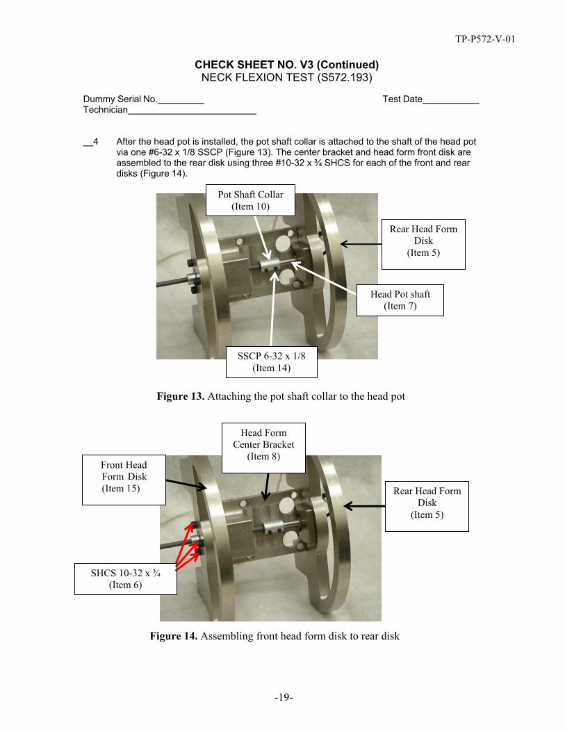
4 After the head pot is installed, the pot shaft collar is attached to the shaft of the head pot via one #6-32 x 1/8 SSCP (Figure 13). The center bracket and head form front disk are assembled to the rear disk using three #10-32 x ¾ SHCS for each of the front and rear disks (Figure 14).
SSCP 6-32 x 1/8 (Item 14)
Head Pot shaft (Item 7)
Rear Head Form Disk
(Item 5)
Pot Shaft Collar (Item 10)
Figure 13. Attaching the pot shaft collar to the head pot
SHCS 10-32 x ¾ (Item 6)
Rear Head Form Disk
(Item 5)
Front Head Form Disk (Item 15)
Head Form Center Bracket
(Item 8)
Figure 14. Assembling front head form disk to rear disk

TP-P572-V-01
CHECK SHEET NO. V3 (Continued) NECK FLEXION TEST (S572.193)
-20-
Dummy Serial No. Technician
Test Date
5 The pot extension shaft is attached to the pot shaft collar via two (perpendicular) #6-32 x 1/8 SSCP (Figure 15). The retaining collar is secured to the extension shaft on the outside of the front head form disk with one #6-32 x 1/8 SSCP (Figure 16).
Two SSCP 6-32 x 1/8 installed
perpendicular to one another
Pot Shaft Collar (Item 10)
Pot Extension Shaft (Item 11)
Figure 15. Attaching the pot extension shaft to the pot shaft collar
Pot Extension Shaft (Item 11)
Retaining Collar (Item 13)
SSCP 6-32 x 1/8 (Item 14)
Head Form Front Disk (Item 15)
Figure 16. Attaching the retaining collar to the pot extension shaft

TP-P572-V-01
CHECK SHEET NO. V3 (Continued) NECK FLEXION TEST (S572.193)
-21-
Dummy Serial No. Technician
Test Date
6 Table II lists the parts that make up the head form assembly. The base of the neck is mounted on the neck mounting plate with four 10-24 x ⅝ SHCS and four flat washers (Figure 16), with the bib simulator located between the base of the neck and the neck mounting plate. Four ¼ -20 SHCS are used to mount the neck and head form assembly to the Part 572 neck pendulum.
Table II. Head Form Assembly Parts Item
Number Quantity Part Number Description
1 1 180-9002 Head Form 2 1 180-9060 Spacer 3 1 180-9040 Potentiometer Inner-Rod Assembly 4 1 180-9030 Potentiometer Outer-Rod Assembly 5 1 180-2000 Neck Assembly (Ref.) 6 1 180-9058 Neck Mounting Plate 7 2 9001021 Screw, SHSS 5/16 x 5/8 Shoulder w/ ¼-
20 x 7/16 Thread 8 2 180-9021 Bracket, Potentiometer Pivot 9 4 9000155 Screw, SSCP #6-40 x ¼ 10 2 SA572-S51 Chest Rotary Potentiometer 11 2 180-9010 Potentiometer Housing Assembly 12 1 180-3006 Simulator, Bib 13 4 9000224 Screw, SHCS #10-24 x 5/8
The Upper Neck Bracket (180-2006) of the Neck Assembly is not utilized for Neck Qualification Tests.
7 Soak the neck assembly in a controlled environment at a temperature and relative humidity indicated in Table V3 for at least four hours prior to a test. Record the length of time for the soak and the maximum and minimum temperature and humidity in Table V3. Verify that each measurement meets specification by indicating “Pass” or “Fail” in the far right column.
8 Inspect the neck for deformation, tears or breaks in the rubber. Replace the neck if deformation or damage is observed.
9 Inspect the two nodding blocks for deformation or damage. Deformed nodding blocks can cause the head to rattle and allow improper loading of the nodding joint and should be replaced.
10 Remove the hex jam nut (9000018), 1.06 OD x .53 ID x .06 washer (9001260), and lower neck bushing (180-2005) from the end of the neck cable.
11 Uninstall the four #10-24 x 5/8 FHCS to detach the nodding joint assembly (with nodding blocks) from the neck (Figure 17). Remove the neck cable (180-2013) from the neck assembly (180-2000). The upper neck bushing should be present, but need not be removed.

TP-P572-V-01
CHECK SHEET NO. V3 (Continued) NECK FLEXION TEST (S572.193)
-22-
Dummy Serial No. Technician
Test Date
Figure 17. Removing the nodding joint assembly 12 Inspect the neck cable by observing the condition of the strands. If they are not tightly
wound, if frays are visible, or the cable appears larger in diameter on one end, replace the cable. If the cable is permanently bent, replace the cable.
13 With the upper neck bushing installed, insert the neck cable through the top of the neck.

TP-P572-V-01
CHECK SHEET NO. V3 (Continued) NECK FLEXION TEST (S572.193)
-23-
14 Insert the bib simulator over the threaded end of the neck cable taking care to align the holes in the bib simulator with those in the neck (Figure 18).
15 Orient the molded neck so that the front of the neck (which has slits) faces the front of the neck mounting plate. Assemble the molded neck to the neck mounting plate with four #10- 24 x ⅝ SHCS and four flat washers (Figure 19). (Note: the upper neck bracket (180-2006) of the neck assembly is not used in the neck qualification test.)
Figure 18. Install bib simulator
Front of Neck Mounting Plate
Front of Neck (with Slits)
Figure 19. Assemble molded neck to neck mounting plate

TP-P572-V-01
CHECK SHEET NO. V3 (Continued) NECK FLEXION TEST (S572.193)
-24-
16 Insert the lower neck bushing into the neck mounting plate over the neck cable, then the 1.06 OD x .53 ID x .06 washer and finally the hex jam nut (Figure 20). Torque the nut to 10-12 in-lbs (Figure 21). If the proper torque cannot be achieved, replace the neck cable.
Figure 20. Install lower neck bushing, washer, and hex nut onto neck cable
Figure 21. Torque hex nut on neck cable to 10-12 in-lbs

TP-P572-V-01
CHECK SHEET NO. V3 (Continued) NECK FLEXION TEST (S572.193)
-25-
17 Reinstall the nodding joint assembly with nodding blocks using the four #10-24 x 5/8 FHCS (Figure 22).
18 Install the potentiometer pivot brackets to the neck mounting plate using one SHSS 5/16 x 5/8 shoulder screw with ¼-20 x 7/16 thread for each bracket (Figure 23).
Note - For a left side test (shown) the pivot bracket is placed in the innermost threaded hole on the right side of the neck, and on the outermost threaded hole on the left side of the neck.
Figure 22. Reinstall neck nodding joint assembly
Pivot bracket in outermost
threaded hole on left side of neck
right side of neck
Pivot bracket in innermost
threaded hole on right side of neck
Front of Neck
Figure 23. Install potentiometer brackets (left side neck test illustrated)

TP-P572-V-01
CHECK SHEET NO. V3 (Continued) NECK FLEXION TEST (S572.193)
-26-
19 Prior to installing the neck to the six axis upper neck load cell, install the brass nodding joint washers by holding them on either side of the pivot hole on the neck cap (Figure 24); orient the upper neck load cell so that the straight edge of the load cell is towards the back of the neck, and press the upper neck load cell onto the pivot while maintaining the positioning of the brass washers (Figure 25).
Figure 24. Install brass nodding joint washers
Straight edge of load cell towards
back of neck
Front of Neck
Figure 25. Install the upper neck load cell

TP-P572-V-01
CHECK SHEET NO. V3 (Continued) NECK FLEXION TEST (S572.193)
-27-
20 In order to insert the pivot pin through the neck, the brass nodding joint washers must be aligned properly with the holes. A punch tool or other appropriate tool, may aid in this alignment (Figure 26).
21 Uninstall the two #8-32 x 1/4 set screws located on the back underside of the load cell. Insert the neck pivot pin so that the “flat” sections of the pin face the rear of the load cell. Using a nylon or similar “soft” mallet so that the load cell will not be damaged (Figure 27), drive the neck pivot pin into the nodding joint. When the flat portions of the pivot pin are visible through the set screw holes, the pin is properly located. Reinstall and tighten the set screws.
Figure 26. Align brass nodding joint washers with holes
Set Screw Locations
Figure 27. Insert and install neck pivot pin

TP-P572-V-01
CHECK SHEET NO. V3 (Continued) NECK FLEXION TEST (S572.193)
-28-
22 Install the upper neck load cell to the head form using four ¼ - 28 x ½ SHCS (Figure 28). Be sure to orient the neck appropriately with the Rear Head Form Disk at the rear of the neck and the Front Head Form Disk at the front of the neck. Recall that the straight edge of the load cell corresponds to the back of the neck and the front of the neck has slits.
Figure 28. Install upper neck load cell to head form
TP-P572-V-01
CHECK SHEET NO. V3 (Continued) NECK FLEXION TEST (S572.193)
-29-
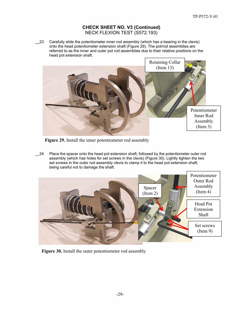
23 Carefully slide the potentiometer inner rod assembly (which has a bearing in the clevis) onto the head potentiometer extension shaft (Figure 29). The pot/rod assemblies are referred to as the inner and outer pot rod assemblies due to their relative positions on the head pot extension shaft.
Potentiometer Inner Rod Assembly (Item 3)
Retaining Collar (Item 13)
Figure 29. Install the inner potentiometer rod assembly
24 Place the spacer onto the head pot extension shaft, followed by the potentiometer outer rod assembly (which has holes for set screws in the clevis) (Figure 30). Lightly tighten the two set screws in the outer rod assembly clevis to clamp it to the head pot extension shaft, being careful not to damage the shaft.
Set screws (Item 9)
Head Pot Extension
Shaft
Spacer (Item 2)
Potentiometer Outer Rod Assembly (Item 4)
Figure 30. Install the outer potentiometer rod assembly

TP-P572-V-01
CHECK SHEET NO. V3 (Continued) NECK FLEXION TEST (S572.193)
-30-
25 Install the chest rotary potentiometers into the potentiometer housing assemblies (Figure 31). During installation, it is important to insert the roll pin, which is press fit into the potentiometer housing assembly, into one of the locator holes of the potentiometer. Inserting the roll pin of the potentiometer housing assembly into the locator hole of the potentiometer ensures that the potentiometer will not slip within the assembly during testing. The potentiometer is secured to the assembly with an internal tooth lock washer and threaded hex nut.
Chest Rotary Potentiometer
(Item 10)
Threaded Hex Nut (part of
Rotary Pot)
Roll Pin (part of
Potentiometer Housing
Assembly)
Internal Tooth Lock Washer
(part of Rotary Pot)
Potentiometer Housing
Assembly (Item 11)
Be sure to install
Potentiometer Housing
Assembly such that the pressed Roll
Pin is inserted into the
locater hole in the
Potentiometer.
Figure 31. Assembling chest rotary potentiometer and potentiometer housing assembly
26 Slide a potentiometer housing assembly onto each potentiometer rod. 27 Install the shaft of the potentiometer on the inner pot rod onto the inner potentiometer pivot
bracket (Figure 32). Note that the pivot bracket is bolted to the innermost bolt location for this pot (Figures 23 and 32). Tighten the two #6-40 x ¼ SSCP set screws into the pot shaft (Figures 32 and 33).
NOTE -These potentiometers are referred to as “forward” and “rearward” or “fore” and “aft” to describe their position on the neck mounting plate relative to the honeycomb. Regardless of which side of the neck is tested (left or right), the inner pot rod should always be attached to the pot housing assembly that is farthest from the honeycomb, referred to as the Aft/Inner Pot; the outer pot rod should always be attached to the pot housing assembly that is nearest to the honeycomb, referred to as the Fore/Outer Pot. It is important to assure that the potentiometers are in the correct locations in order to obtain the appropriate rotation measurements

TP-P572-V-01
CHECK SHEET NO. V3 (Continued) NECK FLEXION TEST (S572.193)
-31-
28 Repeat the same installation procedure for the potentiometer on the outer pot rod using the outer potentiometer pivot bracket. For the outer rod, be sure the pot bracket is installed in the outermost position (Figure 23).
Set Screws
Aft/Inner Pot Rod
Assure that pot
bracket is in inner position
Potentiometer Housing Assembly
Figure 32. Install potentiometer on inner pot rod onto inner potentiometer pivot bracket
Figure 33. Tighten set screws for inner potentiometer pivot bracket
TP-P572-V-01
CHECK SHEET NO. V3 (Continued) NECK FLEXION TEST (S572.193)
-32-
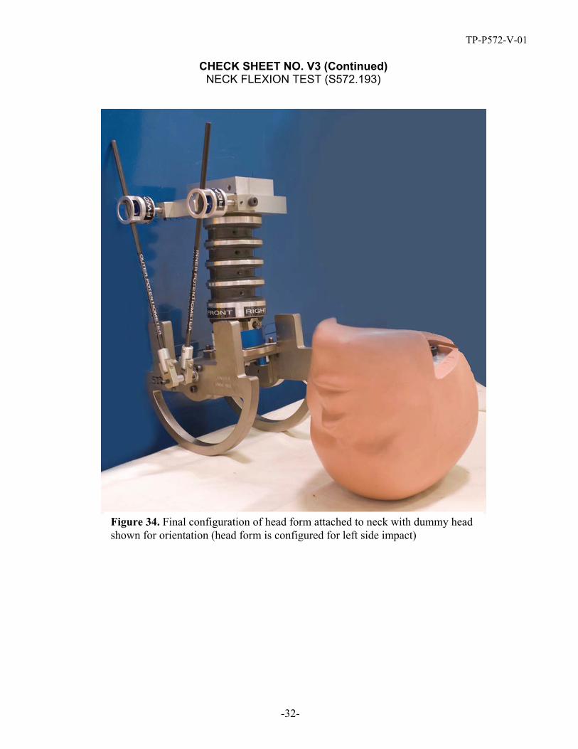
Figure 34. Final configuration of head form attached to neck with dummy head shown for orientation (head form is configured for left side impact)

TP-P572-V-01
CHECK SHEET NO. V3 (Continued) NECK FLEXION TEST (S572.193)
-33-
NECK FLEXION TEST (S572.193)
29 Insert the neck mounting plate into the pendulum such that the impact side of the neck is closest to the honeycomb, screw and tighten with four ¼-20 x ⅝ SHCS. Note that the CG of the head form is not in line with the centerline of the neck, causing the head form to “sag.” Figure 35 shows a neck and head form installed for a left side impact. Figure 36 shows a schematic for the configuration viewed from above.
Note -The outermost pot, which is closest to the honeycomb, is used for obtaining ∆ΘOuter (Figure 39).
CHECK SHEET NO. B3 (Continued) NECK FLEXION TEST (S572.193)
CHECK SHEET NO. B3 (Continued) NECK FLEXION TEST (S572.193)
CHECK SHEET NO. B3 (Continued)
Pot used for obtaining ∆ΘOuter
Figure 35. Pendulum configuration for a left side neck test

TP-P572-V-01
CHECK SHEET NO. V3 (Continued) NECK FLEXION TEST (S572.193)
-34-
HONEYCOMB
Aft/Inner Pot Housing Assembly
Inner Pot Pivot
Bracket
SHSS Pot
Outer Pot Pivot Bracket
Innermost attachment
site
Inner Rod Assembly
Outer Rod Assembly
Head Pot Extension
Shaft
Outermost attachment
site
Fore/Outer Pot Housing Assembly
Direction of motion
Figure 36. Attachment of inner and outer pot rod assemblies to neck mounting plate for left side impact (view from above)

TP-P572-V-01
-35-
CHECK SHEET NO. V3 (Continued) NECK FLEXION TEST (S572.193)
Opposite Side Test Preparation - To test the opposite side of the neck, follow these steps: 1 Remove the entire assembly from the pendulum, rotate it 180 degrees and
reassemble the neck mounting plate to the pendulum. 2 Switch the position of the two potentiometer rod assemblies by removing the potentiometer
pivot brackets at the neck mounting plate and securing the outer rod/pot pivot bracket to the outermost attachment site closest to the honeycomb (i.e., in the fore position) and the inner rod/pot pivot bracket to the innermost attachment site furthest from the honeycomb (i.e., in the aft position) (Figures 37 and 38). When calculating the D-plane rotation, be sure that the potentiometers being used are in the appropriate locations during the test.
Pot used for obtaining ∆ΘOuter
Figure 37 Pendulum configuration for a right side neck test

TP-P572-V-01
CHECK SHEET NO. V3 (Continued) NECK FLEXION TEST (S572.193)
-36-
Front of dummy
Outer rod secured to head pot
shaft
Inner/aft Pot Rod Assembly
Outer/fore Pot Rod
Assembly
Aft pot position
Outermost pot pivot bracket location
Fore pot position
Innermost pot pivot bracket location
Direction of motion
Figure 38. Correct outer and inner pot/rod assembly locations for a right-side test
Conduct the Test, Collect Data and Verify Performance 1 Record the room temperature and relative humidity on the table. Verify that e
measurement meets specifications by indicating “Pass” or “Fail” in the far righach t column.
2 The neck pendulum should have a mass as specified in Figure 22, 49 CFR 572.33. 3 Mount an accelerometer on the pendulum with its sensitive axis on the side of the
pendulum that impacts the honeycomb at the location specified in Figure 22, 49 CFR 572.33.
4 Raise the pendulum and allow it to fall freely such that it achieves an impact velocity of 5.51-5.63 m/s at the time of contact with the arresting block.
5 The pendulum acceleration is filtered using a Channel Class 180 phaseless filter. 6 The potentiometers are filtered using a Channel Class 60 phaseless filter. 7 The neck lateral shear force is filtered using Channel Class 600 phaseless filter for the
purpose of occipital condyle calculation. 8 The neck moment about the x-axis is filtered using Channel Class 600 phaseless filter. 9 Time zero is defined as the time of contact between the pendulum and the honeycomb. All
channels should be at the zero level at this point.
TP-P572-V-01
CHECK SHEET NO. V3 (Continued) NECK FLEXION TEST (S572.193)
-37-
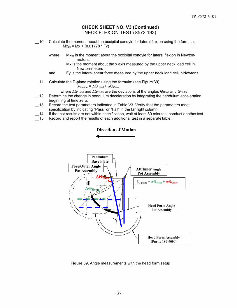
10 Calculate the moment about the occipital condyle for lateral flexion using the formula: Mxoc = Mx + (0.01778 * Fy)
where Mxoc is the moment about the occipital condyle for lateral flexion in Newton- meters,
Mx is the moment about the x axis measured by the upper neck load cell in Newton-meters
and Fy is the lateral shear force measured by the upper neck load cell in Newtons.
11 Calculate the D-plane rotation using the formula: (see Figure 39) βD-plane = ∆ΘHead + ∆ΘOuter
where ∆ΘHead and ∆ΘOuter are the deviations of the angles ΘHead and ΘOuter 12 Determine the change in pendulum deceleration by integrating the pendulum acceleration
beginning at time zero. 13 Record the test parameters indicated in Table V3. Verify that the parameters meet
specification by indicating “Pass” or “Fail” in the far right column. 14 If the test results are not within specification, wait at least 30 minutes, conduct another test. 15 Record and report the results of each additional test in a separate table.
Figure 39. Angle measurements with the head form setup
Direction of Motion
∆ΘOute
∆ΘHea
Fore/Outer Angle Pot Assembly
Pendulum Base Plate
Head Form Assembly (Part # 180-9000)
Head Form Angle Pot Assembly
βD-plane = ∆ΘHead + ∆ΘOuter
Aft/Inner Angle Pot Assembly
Figure 39. Angle measurements with the head form setup

TP-P572-V-01
CHECK SHEET NO. V3 (Continued) NECK FLEXION TEST (S572.193)
-38-
Table V3. Neck Flexion Test
Tested Parameter
Units
Spec.
Result Pass/ Fail
Neck Assembly Soak Time Minutes ≥240
Temperature – During Soak
Max C° 20.6 to 22.2
Min Humidity – During Soak
Max % 10.0 to 70.0
Min
Temperature – During test C° 20.6 to 22.2
Humidity – During test % 10.0 to 70.0 Pendulum Velocity m/s 5.51 to 5.63
Pendulum ∆V
10 ms m/s -2.20 to -2.80 15 ms m/s -3.30 to -4.10 20 ms m/s -4.40 to -5.40 25 ms m/s -5.40 to -6.10 >25.0 <100 ms m/s -5.50 to -6.20
Maximum D-plane rotation deg 71 to 81 Time of Maximum D-plane rotation ms 50 to 70 Peak Occ. Condyle Moment Nm -44 to -36 Time of Moment Decay ms 102 to 126
Signature Completion Date

TP-P572-V-01
-39-
1. 2.
CHECK SHEET NO. V4 SHOULDER IMPACT TEST (S572.194)
Dummy Serial No. Technician
Test Date
Pretest Preparation 1 Soak the dummy in a controlled environment at a temperature and relative humidity
indicated in Table V4 for at least four hours prior to a test. Record the length of time for the soak and the maximum and minimum temperature and humidity in Table V4. Verify that each measurement meets specification by indicating “Pass” or “Fail” in the far right column.
2 Install the thoracic and abdominal pads using cable ties. 3 Place the chest jacket on the dummy. 4 Clothe the dummy with cotton underwear pants, cut off just above the knees, but no shirt or
shoes. 5 Ground the dummy using a cable between a metal component of the dummy and the
ground. 7 Align the upper and lower neck brackets of the neck load cell replacement so that the top
edges are flush with one another. 8 Place the bench (Figure 40) in the probe’s impact area so that the dummy can be impacted
in the shoulder.
Figure 40. Certification bench seat specifications
9 Seat the dummy on a sheet of 387 x 521 mm PTFE (Teflon) (2-mm thick) on the bench. Position the dummy so that the outermost pelvic flesh is within 10 mm of the edge of the Teflon sheet; the edge of the sheet must be along the impact side of the bench’s seat pan (Figure 41).
10 Place a sheet of 514 x 514 mm PTFE (Teflon) (2-mm thick) between the seatback and the dummy’s posterior thorax; the edge of the sheet must be along the impact side of the bench’s seatback.

TP-P572-V-01
CHECK SHEET NO. V4 (Continued) SHOULDER IMPACT TEST (S572.194)
-40-
11 Be sure that the molded arm assembly plug (drawing 180-6019) is completely inserted into the arm and secured to the arm bone with screws.
12 Position the arm so that it points forward at 90° ± 2º relative to the inferior-superior orientation of the upper torso (spine box).
Figure 41. Shoulder impact test configuration for SID-IIsD
90°
387 x 521 x 2 mm Teflon
514 x 514 x 2 mm
Teflon
13 Position the dummy so that the centerline of the arm bolt (ref. item 23 in drawing 180-3000) is centered on the centerline of the impact probe within 2 mm. The face of the impactor should be parallel to, and just touching, the surface of the molded arm assembly plug when the pendulum is at its lowest position during travel.
14 Push the dummy’s chest towards the seatback, so that the back of the thorax is touching the seatback (Figure 42).

TP-P572-V-01
CHECK SHEET NO. V4 (Continued) SHOULDER IMPACT TEST (S572.194)
-41-
Thighs touching seat pan
Dummy’s back against seatback
Figure 42. Impact probe and dummy seating position

TP-P572-V-01
CHECK SHEET NO. V4 (Continued) SHOULDER IMPACT TEST (S572.194)
-42-
15 Push the femurs towards the seat pan so that the thighs are in contact with the seat. 16 Move the legs together so that the knees are as close together as possible (Figure 43).
Thighs touching seat pan
Knees as close together as
possible
Figure 43. SID-IIsD leg positioning
17 Position the feet so that they are vertical and as close together as possible, with the heels touching the surface of the support table (Figure 44).
Heels touching table
Feet vertical
Figure 44. SID-IIsD feet positioning

TP-P572-V-01
CHECK SHEET NO. V4 (Continued) SHOULDER IMPACT TEST (S572.194)
-43-
18 Adjust the dummy so that the thoracic lateral plane is 0° ± 1 relative to horizontal as referenced at the top surface of the lower neck bracket (Figure 45).
Figure 45. Adjusting the SID-IIsD dummy in the lateral direction

TP-P572-V-01
CHECK SHEET NO. V4 (Continued) SHOULDER IMPACT TEST (S572.194)
-44-
19 Adjust the dummy so that the thoracic fore/aft plane measures 24.6 ± 2° relative to horizontal. This measurement can be taken at the top of the shoulder rib mount (Figure 46).
Figure 46. Adjusting the SID-IIsD in the fore/aft plane
Conduct the Test, Collect Data and Verify Performance 20 Record the room temperature and humidity in Table V4. Verify that the temperatur
relative humidity meets specification by indicating “Pass” or “Fail” in the far right co1
e and lumn.
21 The impactor should have a mass of 13.97 ± 0.23 kg with a 120.7 ± 0.25 mm face diameter, and a 12.7 mm radius.
22 Mount an accelerometer on the impactor with its sensitive axis in line with the longitudinal centerline of the test probe.
23 Release the impactor so that it achieves a velocity between 4.2 – 4.4 m/s at the instant of contact with the dummy.
24 At the instant of contact, the impactor should be horizontal ± 1º with its centerline within 2 mm of the dummy’s arm rotation centerline (ref. item 23 in drawing 180-3000).
1 Mass includes probe mass and all rigidly attached hardware, plus 1/3 of supporting cable weight.

TP-P572-V-01
CHECK SHEET NO. V4 (Continued) SHOULDER IMPACT TEST (S572.194)
-45-
25 The impactor and spine accelerations are collected and filtered using a Channel Class 180 phaseless filter.
26 The shoulder deflection is collected and filtered using a Channel Class 600 phaseless filter. 27 Time zero is defined as the time of contact between the impactor probe and the shoulder.
All channels should be at a zero level at this point. 28 Record impactor velocity, peak impactor acceleration, peak shoulder deflection and peak
lateral spine acceleration in Table V4. Verify that each measurement meets specification by indicating “Pass” or “Fail” in the far right column.
29 If test results do not meet specifications, wait at least 30 minutes, conduct another test. 30 Record and report the results of each additional test in a separate table.
Table V4. Shoulder Impact Test
Tested Parameter
Units
Spec.
Result Pass/ Fail
Dummy Soak Time Minutes ≥180
Temperature – During Soak
Max C° 20.6 to 22.2 Min
Relative Humidity – During Soak
Max % 10.0 to 70.0 Min
Temperature – During test C° 20.6 to 22.2
Relative Humidity - During test % 10.0 to 70.0 Impactor Velocity m/s 4.2 to 4.4 Peak Shoulder Deflection mm 28 to 37 Peak Lateral Spine (T1) Acceleration (Y) G’s 17 to 22 Peak Impactor Acceleration G’s 13 to 18
Signature Completion Date

TP-P572-V-01
-46-
CHECK SHEET NO. V5 THORAX WITH ARM IMPACT TEST (S572.195)
Dummy Serial No. Technician
Test Date
Pretest Preparation 1 Soak the dummy in a controlled environment at a temperature and relative humidity
indicated in Table V5 for at least three hours prior to a test. Record the length of time for the soak and the maximum and minimum temperature and humidity in Table V5. Verify that each measurement meets specification by indicating “Pass” or “Fail” in the far right column
2 Install the thoracic and abdominal pads using cable ties2. 3 Place the chest jacket on the dummy. 4 Place on the dummy’s lower torso cotton underwear pants, cut off just above the knees, but
no shirt or shoes. 5 Ground the dummy using a cable between a metal component of the dummy and the
ground. 6 Align the upper and lower neck brackets of the load cell replacement so that the top edges
are flush with one another. DO NOT USE THE LOWER NECK LOAD CELL. (Figure 47)
Upper Neck Bracket
Lower Neck Bracket
Align edges
Figure 47. Aligning the upper and lower neck brackets flush for testing.
7 Place the bench seat in the probe’s impact area. 8 Seat the dummy on a sheet of 387 x 521 mm PTFE (Teflon) (2 mm thick) on the bench.
Position the dummy within 25mm of the edge of the Teflon sheet; the edge of the sheet should be along the impact side of the bench’s seat pan.
9 Place a sheet of 514 x 514 mm PTFE (Teflon) (2 mm thick) between the seatback and the dummy’s posterior thorax; the edge of the sheet should be along the impact side of the bench’s seatback.
10 Position the impact arm to its lowest detent, so that it points downward, parallel to the seatback.
2 See Attachment of Thoracic and Abdominal Pads in the SID-IIsD.

TP-P572-V-01
-47-
CHECK SHEET NO. V5 (Continued) THORAX WITH ARM IMPACT TEST (S572.195)
387 x 521 x 2 mm Teflon
Dummy’s back against seatback
Thighs touching seatpan
514 x 514 x 2 mm
Teflon
Figure 48. Thorax with arm impact test configuration for SID-IIsD
TP-P572-V-01
CHECK SHEET NO. V5 (Continued) THORAX WITH ARM IMPACT TEST (S572.195)
-48-
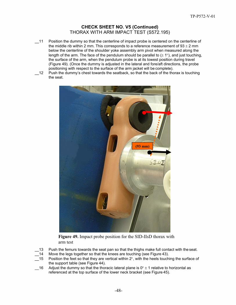
11 Position the dummy so that the centerline of impact probe is centered on the centerline of the middle rib within 2 mm. This corresponds to a reference measurement of 93 ± 2 mm below the centerline of the shoulder yoke assembly arm pivot when measured along the length of the arm. The face of the pendulum should be parallel to (± 1°), and just touching, the surface of the arm, when the pendulum probe is at its lowest position during travel (Figure 49). (Once the dummy is adjusted in the lateral and fore/aft directions, the probe positioning with respect to the surface of the arm jacket will be complete).
12 Push the dummy’s chest towards the seatback, so that the back of the thorax is touching the seat.
(93 mm)
Figure 49. Impact probe position for the SID-IIsD thorax with arm test
13 Push the femurs towards the seat pan so that the thighs make full contact with the seat. 14 Move the legs together so that the knees are touching (see Figure 43). 15 Position the feet so that they are vertical within 2°, with the heels touching the surface of
the support table (see Figure 44). 16 Adjust the dummy so that the thoracic lateral plane is 0° ± 1 relative to horizontal as
referenced at the top surface of the lower neck bracket (see Figure 45).

TP-P572-V-01
CHECK SHEET NO. V5 (Continued) THORAX WITH ARM IMPACT TEST (S572.195)
-49-
17 Adjust the dummy so that the thoracic fore/aft plane measures 24.6 ± 2° relative to horizontal. This measurement can be taken at the top of the shoulder rib mount (Figure 46).
Conduct the Test, Collect Data and Verify Performance 18 Record the room temperature and humidity in Table V5. Verify that the temperature and
relative humidity meets specification by indicating “Pass” or “Fail” in the far right column 19 The impactor shall have a mass of 13.97 ± 0.23 kg 3 with a 120.7 ± 0.25 mm face diameter,
and a 12.7 mm radius. 20 Mount an accelerometer on the impactor with its sensitive axis in line with the longitudinal
centerline of the impactor. 21 Release the impactor so that it achieves a velocity 6.6 – 6.8 m/s at the instant of contact
with the dummy. 22 At the instant of contact, the impactor should be horizontal ± 1º, and the centerline of the
probe should be within 2 mm of the centerline of the middle rib. 23 The data acquisition system conforms to SAE Recommended Practice J211. 24 Collect the impactor and spine accelerations and filter data using a Channel Class 180
phaseless filter. 25 Collect shoulder and thoracic deflections and filter using a Channel Class 600 phaseless
filter. 26 Time zero is defined as the time of contact between the impactor and the arm. All
channels should be at a zero level at this point. 27 Record the peak impactor acceleration, peak rib deflections and peak spine accelerations
in Table V5. Verify that each measurement meets specification by indicating “Pass” or “Fail” in the far right column.
28 If test results do not meet specifications, wait at least 30 minutes, conduct another test. 29 Record and report the results of each additional test in a separate table.
3 Mass includes impactor mass and all rigidly attached hardware, plus 1/3 of supporting cable weight.

TP-P572-V-01
CHECK SHEET NO. V5 (Continued) THORAX WITH ARM IMPACT TEST (S572.195)
-50-
Table V5. Thorax with Arm Impact Test
Tested Parameter
Units
Specification
Result Pass/ Fail
Dummy Soak Time Minutes ≥180
Temperature - During Soak
Max °C 20.6 to 22.2 Min °C
Relative Humidity - During Soak
Max % 10.0 to 70.0 Min %
Temperature – During test °C 20.6 to 22.2
Relative Humidity – During test % 10.0 to 70.0 Impactor Velocity m/s 6.6 to 6.8 Peak Shoulder Deflection mm 31 to 40 Peak Upper Rib Deflection mm 25 to 32 Peak Middle Rib Deflection mm 30 to 36 Peak Lower Rib Deflection mm 32 to 38 Peak Upr Spine (T1) Acceleration (Y) G’s 34 to 43 Peak Lower Spine (T12) Accel (Y) G’s 29 to 37 Peak Impactor Acceleration G’s 30 to 36
Signature Completion Date

TP-P572-V-01
-51-
CHECK SHEET NO. V6 THORAX WITHOUT ARM IMPACT TEST (S572.196)
Pretest Preparation 1 Soak the dummy in a controlled environment at a temperature and relative humidity
indicated in Table V6 for at least three hours prior to a test. Record the length of time for the soak and the maximum and minimum temperature and humidity in Table V6. Verify that each measurement meets specification by indicating “Pass” or “Fail” in the far right column.
2 Remove the arm on the impact side. 3 Install the thoracic and abdominal pads using cable ties4. 4 Place the chest jacket on the dummy. 5 The dummy should wear cotton underwear pants, cut off just above the knees, but no shirt
or shoes. 6 Ground the dummy using a cable between a metal component of the dummy and the
ground. 7 Align the upper and lower neck brackets so that the top edges are flush. 8 Place the bench in the pendulum’s impact area so that the dummy can be impacted in the
thorax. 9 Seat the dummy on a sheet of 387 x 521 mm PTFE (Teflon) (2 mm thick) on the bench.
Position the dummy within 25mm of the edge of the Teflon sheet; the edge of the sheet should be along the impact side of the bench’s seat pan (Figure 50).
10 Place a sheet of 514 x 514 mm PTFE (Teflon) (2 mm thick) between the seatback and the dummy’s posterior thorax; the edge of the sheet should be along the impact side of the bench’s seatback.
11 Position the dummy so that the centerline of impact probe is vertically centered on the centerline of the middle thoracic rib within 2 mm. This corresponds to a reference measurement of 93 ± 2 mm below the centerline of the shoulder yoke assembly arm pivot when measured along a line parallel to the seatback (Figure 51). The center point of the impactor face is aligned horizontally with a line parallel to the seatback incline passing through the center of the shoulder yoke assembly arm pivot. The face of the impactor should be approximately parallel to, and just touching, the surface of the thorax, when the pendulum is at its lowest position during travel. Once the dummy is adjusted in the lateral and fore/aft directions, the impactor positioning with respect to the surface of the thorax jacket will be complete.
4 See Attachment of Thoracic and Abdominal Pads in the SID-IIsD.

TP-P572-V-01
CHECK SHEET NO. V6 (Continued) THORAX WITHOUT ARM IMPACT TEST (S572.196)
-52-
12 Push the dummy’s chest towards the seatback, so that the back of the thorax is touching the seat.
387 x 521 x 2 mm Teflon
514
x 51
4 x
2 m
m T
eflo
n
Figure 50. Thorax without arm impact test configuration for SID-IIsD

TP-P572-V-01
CHECK SHEET NO. V6 (Continued) THORAX WITHOUT ARM IMPACT TEST (S572.196)
-53-
Dummy’s back against seatback
(93 mm)
Figure 51. Impactor position for the SID-IIsD thorax without arm test
13 Move the legs together so that the knees are touching (see Figure 43). 14 Position the feet so that they are vertical and as close together as possible, with the heels
touching the surface of the support table (see Figure 44). 15 Adjust the dummy so that the thoracic lateral plane is 0° ± 1° relative to horizontal (see
Figure 45). 16 Adjust the dummy so that the thoracic fore/aft plane measures 24.6 ± 2° relative to
horizontal. This measurement can be taken at the top of the shoulder rib mount (see Figure 46). Once this positioning is complete, the face of the impactor should be approximately parallel to (± 1°), and just touching, the surface of the thorax, when the pendulum is at its lowest position during travel.
Conduct the Test, Collect Data and Verify Performance 17 Record the room temperature and humidity in Table V6. Verify that the temperature and
relative humidity meets specification by indicating “Pass” or “Fail” in the far right column 18 The impactor shall have a mass of 13.97 ± 0.23 kg with a 120.7 mm face diameter, and a
12.7 mm radius. 19 Mount an accelerometer on the impactor with its sensitive axis in line with the longitudinal
centerline of the test probe. 20 Release the impactor at an impact speed between 4.2 - 4.4 m/s at the instant of contact
with the dummy. 21 The data acquisition system should conform to SAE Recommended Practice J211.

TP-P572-V-01
CHECK SHEET NO. V6 (Continued) THORAX WITHOUT ARM IMPACT TEST (S572.196)
-54-
22 The impactor and spine accelerations are collected and filtered using a Channel lass 180 phaseless filter.
23 The rib deflections are collected and filtered using a Channel Class 600 phaseless filter. 24 Time zero is defined as the time of contact between the impactor and the thorax. All
channels should be at a zero level at this point. 25 Record the peak impactor acceleration, peak rib deflections and peak spine accelerations
in Table V6. Verify that each measurement meets specification by indicating “Pass” or “Fail” in the far right column.
26 If test results do not meet specifications, wait at least 30 minutes, conduct another test. 27 Record and report the results of each additional test in a separate table.
Table V6. Thorax without Arm Impact Test
Tested Parameter
Units
Specification
Result Pass/ Fail
Dummy Soak Time Minutes ≥180
Temperature - During Soak
Max °C 20.6 to 22.2 Min °C
Relative Humidity - During Soak
Max % 10.0 to 70.0 Min %
Temperature – During test °C 20.6 to 22.2
Relative Humidity – During test % 10.0 to 70.0 Impactor Velocity m/s 4.2 to 4.4 Peak Upper Rib Deflection mm 32 to 40 Peak Middle Rib Deflection mm 39 to 45 Peak Lower Rib Deflection mm 35 to 43 Peak Upr Spine (T1) Acceleration (Y) G’s 13 to 17 Peak Lower Spine (T12) Accel (Y) G’s 7 to 11 Peak Impactor Acceleration G’s 14 to 18
Signature Completion Date
TP-P572-V-01
-55-
CHECK SHEET NO. V7 ABDOMEN IMPACT TEST (S572.197)
Pretest Preparation 1 Soak the dummy in a controlled environment at a temperature and relative humidity
indicated in Table V7 for at least three hours prior to a test. Record the length of time for the soak and the maximum and minimum temperature and humidity in Table V7. Verify that each measurement meets specification by indicating “Pass” or “Fail” in the far right column.
2 Remove the arm on the impact side. 3 Install the thoracic and abdominal pads using cable ties5. 4 Place the chest jacket on the dummy. 5 The dummy should wear cotton underwear pants, cut off just above the knees, for this
procedure. No shirt or shoes should be worn. 6 Ground the dummy using a cable between a metal component of the dummy and the
ground. 7 Align the upper and lower neck brackets so that the top edges are flush. 8 Place the bench in the pendulum’s impact area so that the dummy can be impacted in
the abdomen. 9 Seat the dummy on a sheet of 387 x 521 mm PTFE (Teflon) (2 mm thick) on the bench.
Position the dummy within 25mm of the edge of the Teflon sheet; the edge of the sheet should be along the impact side of the bench’s seat pan.
10 Place a sheet of 514 x 514 mm PTFE (Teflon) (2 mm thick) between the seatback and the dummy’s posterior thorax; the edge of the sheet should be along the impact side of the bench’s seatback
5 See Attachment of Thoracic and Abdominal Pads in the SID-IIsD.

TP-P572-V-01
CHECK SHEET NO. V7 (Continued) ABDOMEN IMPACT TEST (S572.197)
-56-
387 x 521 x 2 mm Teflon
514
x 51
4 x
2 m
m T
eflo
n
Figure 52. Abdomen impact test configuration for SID-IIsD
11 Position the dummy so that the centerline of impact probe is centered vertically on the midpoint between the two abdominal ribs within 2 mm. This corresponds to a reference measurement of 208 ± 2 mm below the centerline of the shoulder yoke assembly arm pivot when measured along a line parallel to the seatback (Figure 52). The center point of the impactor face is aligned horizontally with a line parallel to the seatback incline passing through the center of the shoulder yoke assembly arm rotation pivot. The face of the probe should be approximately parallel to, and just touching, the surface of the abdomen, when the pendulum probe is at its lowest position during travel. (Once the dummy is adjusted in the lateral and fore/aft directions, the probe positioning with respect to the surface of the jacket at the abdomen will be complete).

TP-P572-V-01
CHECK SHEET NO. V7 (Continued) ABDOMEN IMPACT TEST (S572.197)
-57-
Dummy’s back against
(208 mm)
Figure 53. Impact probe position for the SID-IIsD abdomen test ush the dummy’s chest towards the seatback, so that the back of the thorax is touching 12 P
the seat (Figure 53). 13 Push the femurs towards the seat pan so that the thighs are in contact with the seat. 14 Move the legs together so that the knees are touching (see Figure 43). 15 Position the feet so that they are vertical within 2°, with the heels touching the surface of
the support table (see Figure 44). 16 Adjust the dummy so that the thoracic lateral plane is 0° ± 1 relative to horizontal (see
Figure 45). 17 Adjust the dummy so that the thoracic fore/aft plane measures 24.6 ± 2° relative to
horizontal. This measurement can be taken at the top of the shoulder rib mount (see Figure 46).

TP-P572-V-01
-58-
CHECK SHEET NO. V7 (Continued) ABDOMEN IMPACT TEST (S572.196)
Conduct Test, Collect Data and Verify Performance 1 Record the room temperature and humidity in Table V7. Verify that the temperature and
relative humidity meets specification by indicating “Pass” or “Fail” in the far right column 2 The impactor shall have a mass of 13.97 ± 0.23 kg 6 with a 76.2 mm face7 and a 12.7 mm
radius. 3 Mount an accelerometer on the impactor with its sensitive axis in line with the longitudinal
centerline of the impactor. 4 Release the impactor at an impact speed between 4.2 - 4.4 m/s. 5 At the instant of contact, the impactor shall be horizontal ± 1° and the centerline of the
impactor shall be within 2 mm of the centerline of the abdominal ribs. 6 The data acquisition system should conform to SAE Recommended Practice J211. 7 The impactor and spine accelerations are collected and filtered using a Channel Class 180
phaseless filter. 8 The abdominal rib deflections are collected and filtered using a Channel Class 600
phaseless filter. 9 Time zero is defined as the time of contact between the impact probe and the abdomen.
All channels should be at a zero level at this point. 10 Record the peak impactor acceleration, peak abdominal rib deflections and peak lower
spine acceleration in Table V7. Verify that each measurement meets specification by indicating “Pass” or “Fail” in the far right column.
11 If test results do not meet specification, wait at least 30 minutes, conduct another test. 12
Record and report the test results of each additional test in a separate table.
Table V7. Abdomen Impact Test
Tested Parameter
Units Specification
Result
Pass/ Fail
Dummy Soak Time Minutes ≥180 Temperature - During Soak
Max °C 20.6 to 22.2
Min °C
Relative Humidity - During Soak
Max % 10.0 to 70.0 Min %
Temperature – During test °C 20.6 to 22.2 Relative Humidity – During test % 10.0 to 70.0 Impactor Velocity m/s 4.2 to 4.4 Peak Upr Abdominal Rib Deflection mm 36 to 47 Peak Lwr Abdominal Rib Deflection mm 33 to 44 Peak Lower Spine (T12) Accel (Y) G’s 9 to 14 Peak Impactor Acceleration G’s 12 to 16
Signature Completion Date
6 Mass includes impactor mass and all rigidly attached hardware, plus 1/3 of supporting cable weight. 7 Note that this impactor face differs from impactor faces used in the other certification tests.

TP-P572-V-01
-59-
CHECK SHEET NO. V8 PELVIS PLUG QUASI-STATIC TEST
Dummy Serial No. Technician
Test Date
1 Clean the contact surfaces of the compression device. 2 Assure that the compression head surface and support surfaces are parallel. 3 Place the pelvis plug on the support surface and center it under the compression head
surface, assuring that the top and bottom of the plug are in full contact with the surfaces. 4 Select a maximum displacement value within the specification box (Figure 56) as a halting
point for the compression head. 5 Configure the compression system to halt (and return) at the specified displacement.
compression head
Plug
support
FOR
CE
Figure 54. Pelvis plug quasi-static test
6 Record the room temperature and humidity in Table V8. Verify that the temperature and relative humidity meets specification by indicating “Pass” or “Fail” in the far right column.
7 Record the serial number of the pelvis plug in Table V8. 8 The force and displacement measurements are collected at a minimum sample rate of
20Hz. 9 Pre-load the pelvis plug to 22.2N (5lb) and zero both the force and displacement
measurement channels. Time zero is defined at this point and all channels should be at a zero level.
10 With the channels at zero level, compress the plug at a quasi-static rate, nominally 12.7mm/min (0.5”/min), but no greater than 50.8mm/min (2”/min).
11 Stop and reverse the compression head when the displacement reaches the preselected value.
12 Plot force (N) versus displacement (mm). Plot displacement (mm) versus time (ms). 13 Record the maximum force achieved at maximum displacement in Table V8. Verify that
the measurements fall within the maximum force and displacement corridors (Figure 56) by indicating “Pass” or “Fail” in the far right column.
14 Wait at least 4 hours before utilizing the pelvis plug in any quasi-static test or full-scale dummy test.

TP-P572-V-01
-60-
CHECK SHEET NO. V8 (Continued) PELVIS PLUG QUASI-STATIC TEST
Figure 55. Force-Displacement characteristics of pelvis plug
(2.5mm, 1306N) (3.0mm, 1361N)
(3.5mm, 1416N) (2.5mm, 1618N)
(3.5mm, 1728N) (3.0mm, 1673N)
Figure 56. Maximum force and displacement corridors for pelvis plug quasi-static test
Table V8. Pelvis Plug Quasi-Static Test
Tested Parameter
Units
Spec.
Result Pass/ Fail
Laboratory Temperature C° 20.6 to 22.2 Laboratory Relative Humidity % 10.0 to 70.0 Maximum Displacement mm see Figure 56
Maximum Force N Pelvis Plug Serial No.

TP-P572-V-01
CHECK SHEET NO. V9 PELVIS ACETABULUM IMPACT TEST (572.198)
Pretest Preparation 1 Soak the dummy in a controlled environment at a temperature and relative humidity
indicated in Table V9 for at least three hours prior to a test. Record the length of time for the soak and the maximum and minimum temperature and humidity in Table V9. Verify that each measurement meets specification by indicating “Pass” or “Fail” in the far right column.
2 Remove the chest jacket from the dummy. 3 Be sure the thoracic and abdominal pads are installed using cable ties8. 4 Install a certified pelvis plug (see Pelvis Plug Quasi-Static Test ) 5 Position the arm on the impact side downwards (lowest detent) and parallel to the
seatback. 6 The dummy should not wear clothing or shoes for this procedure. 7 Ground the dummy using a cable between a metal component of the dummy and the
ground. 8 Align the upper and lower neck brackets so that the top edges are flush. 9 Place the bench in the pendulum’s impact area so that the dummy can be impacted in the
pelvis. 10 Seat the dummy on a sheet of 387 x 521 mm PTFE (Teflon) (2 mm thick) on the bench.
Position the dummy within 25mm of the edge of the Teflon sheet; the edge of the sheet should be along the impact side of the bench’s seat pan.
11 Place a sheet of 514 x 514 mm PTFE (Teflon) (2 mm thick) between the seatback and the dummy’s posterior thorax; the edge of the sheet should be along the impact side of the bench’s seatback (Figure 57).
387 x 521 x 2 mm Teflon
Knees as close together as
possible
514 x 514 x 2 mm Teflon
Figure 57. Pelvis Acetabulum test configuration SID-IIsD
8 See Attachment of Thoracic and Abdominal Pads in the SID-IIsD
-61-

TP-P572-V-01
CHECK SHEET NO. V9 (Continued) PELVIS ACETABULUM IMPACT TEST (572.198)
-62-
11 Position the dummy so that the centerline of impact probe is centered on the centerline of the pelvis plug within 2 mm. The face of the pendulum should be parallel to (± 1°), and just touching, the surface of the pelvis plug, when the pendulum probe is at its lowest position during travel (Figure 58).
Figure 58. Impact probe position for the SID-IIsD pelvis acetabulum test
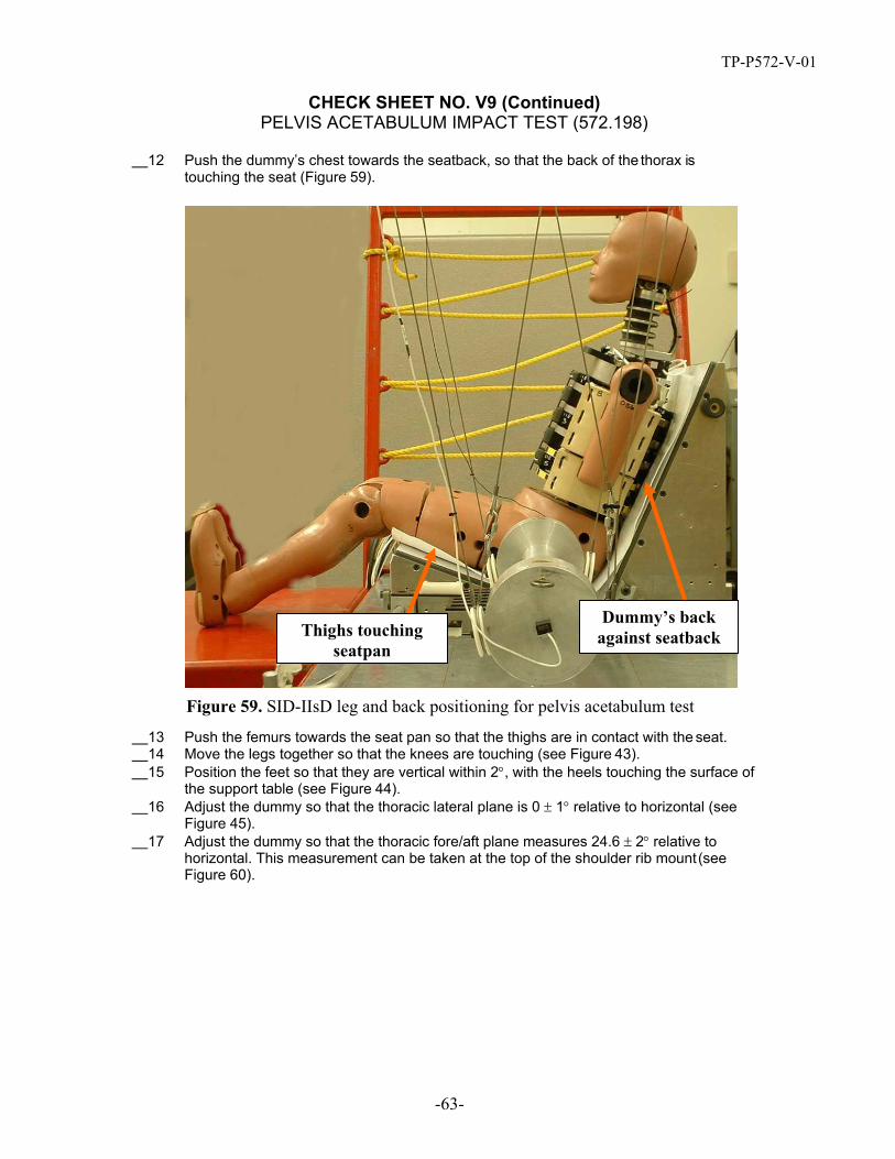
TP-P572-V-01
CHECK SHEET NO. V9 (Continued) PELVIS ACETABULUM IMPACT TEST (572.198)
-63-
12 Push the dummy’s chest towards the seatback, so that the back of the thorax is touching the seat (Figure 59).
Thighs touching seatpan
Dummy’s back against seatback
Figure 59. SID-IIsD leg and back positioning for pelvis acetabulum test
13 Push the femurs towards the seat pan so that the thighs are in contact with the seat. 14 Move the legs together so that the knees are touching (see Figure 43). 15 Position the feet so that they are vertical within 2°, with the heels touching the surface of
the support table (see Figure 44). 16 Adjust the dummy so that the thoracic lateral plane is 0 ± 1° relative to horizontal (see
Figure 45). 17 Adjust the dummy so that the thoracic fore/aft plane measures 24.6 ± 2° relative to
horizontal. This measurement can be taken at the top of the shoulder rib mount (see Figure 60).

TP-P572-V-01
CHECK SHEET NO. V9 (Continued) PELVIS ACETABULUM IMPACT TEST (572.198)
-64-
Figure 60. Adjusting the SID-IIsD in the fore/aft plane for pelvis acetabulum test
Conduct Test, Collect Data and Verify Performance 18 Record the room temperature and humidity in Table V9. Verify that the temperature and
relative humidity meets specification by indicating “Pass” or “Fail” in the far right column. 19 Record the serial number of the pelvis plug in Table V9. 20 The impactor shall have a mass of 13.97 ± 0.23 kg 9 with a 120.7 mm face diameter and a
12.7 mm radius. 21 Mount an accelerometer on the impactor with its sensitive axis in line with the longitudinal
centerline of the impactor. 22 Release the impactor at an impact speed between 6.6 – 6.8 m/s. 23 At the instant of contact, the probe shall be horizontal ± 1° and the centerline of the
impactor shall be within 2 mm of the centerline of the acetabulum load cell. 24 The data acquisition system conforms to SAE Recommended Practice J211. 25 The impactor and pelvis accelerations are collected and filtered using a Channel Class 180
phaseless filter. 26 The acetabulum force is collected and filtered using a Channel Class 600 phaseless filter. 27 Time zero is defined as the time of contact between the impact probe and the pelvis. All
channels should be at a zero level at this point.
9 Mass includes probe mass and all rigidly attached hardware, plus 1/3 of supporting cable weight.

TP-P572-V-01
CHECK SHEET NO. V9 (Continued) PELVIS ACETABULUM IMPACT TEST (572.198)
-65-
28 Record the peak impactor acceleration, peak pelvic acceleration (after 6 ms) and peak acetabulum force in Table V9. Verify that the measurements meet specifications by indicating “Pass” of “Fail” in the far right column.
29 If the test results do not meet specification, wait at least 2 hours, conduct another test. Record test results in a separate table.
30 Discard the impacted pelvis plug and replace it with another certified plug after each test.
Table V9. Pelvis Acetabulum Impact Test
Tested Parameter
Units
Specification
Result Pass/ Fail
Dummy Soak Time Minutes ≥180
Temperature - During Soak
Max °C 20.6 to 22.2
Min °C
Humidity - During Soak
Max % 10.0 to 70.0
Min %
Temperature – During test °C 20.6 to 22.2
Humidity – During test % 10.0 to 70.0 Impactor Velocity m/s 6.6 to 6.8 Peak Impactor Acceleration G’s 38 to 47 Pelvis Acceleration (Y) after 6 ms G’s 34 to 42 Peak Acetabulum Force (Y) kN 3.60 to 4.30 Pelvis Plug Serial No.
Signature Completion Date

TP-P572-V-01
-66-
CHECK SHEET NO. V10 PELVIS ILIAC IMPACT TEST (572.199)
Pretest Preparation 1 Soak the dummy in a controlled environment at a temperature and relative humidity
indicated in Table V10 for at least three hours prior to a test. Record the length of time for the soak and the maximum and minimum temperature and humidity in Table V10. Verify that each measurement meets specification by indicating “Pass” or “Fail” in the far right column.
2 Remove the chest jacket from the dummy. 3 Be sure the thoracic and abdominal pads are installed using cable ties10. 4 Install a certified pelvis plug (see Pelvis Plug Quasi-Static Test). Be certain that the plug
is fully seated in the cavity by pushing on the end of the plug until it fully contacts the acetabulum load cell surface.
5 Position the arm on the impact side downwards (lowest detent) and perpendicular to the seating surface. No bench is used in this procedure.
6 The dummy wears no clothing or shoes for this procedure. 7 The dummy is electrically grounded using a cable between a metal component of the
dummy and the ground. 8 Align the upper and lower neck brackets of the neck load cell replacement so that the top
edges are flush with one another11 (Figure 47). 9 Place two sheets of 2-mm thick Teflon® on top of one another on the seating surface. The
sheets should be large enough to fit completely under the dummy’s pelvis, legs, and feet. 10 Position the dummy on the Teflon® (Figure 61) in the probe’s impact area so that the
dummy can be impacted in the iliac area, with the centerline of the probe aligned with the centerline of the iliac load cell access hole in the pelvis flesh.
11 The probe tip has a 50.8 mm x 88.9 mm face, with an alignment tool access hole in the center. Appendix B includes dimensions for a possible iliac probe face. Care should be taken to adjust probe depth dimensions as needed to maintain the proper 13.97 ± 0.23 kg weight of the probe assembly according to the needs of each test lab.
12 The probe tip should be positioned vertically (0 ± 1º). 13 Position the dummy so that the centerline of impact probe is centered on the centerline of
the iliac load cell access hole. When the pendulum probe is at its lowest position during travel, it should be just touching the pelvis. Push the femurs downward so that the thighs make full contact with the test surface.
10 See Attachment of Thoracic and Abdominal Pads in the SID-IIsD. 11 The lower neck load cell should not be used since its fixed setting creates a neck angle (of ~14º) which is less than the neck angle (of ~19º) when the upper and lower neck brackets are set flush.
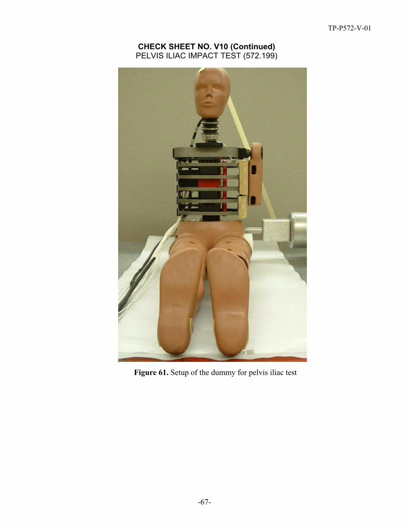
TP-P572-V-01
CHECK SHEET NO. V10 (Continued) PELVIS ILIAC IMPACT TEST (572.199)
-67-
Figure 61. Setup of the dummy for pelvis iliac test

TP-P572-V-01
CHECK SHEET NO. V10 (Continued) PELVIS ILIAC IMPACT TEST (572.199)
-68-
14 Move the legs together so that the knees are as close together as possible (Figure 40). 15 Position the feet so that they are in dorsiflexion with toes angled towards the dummy’s
head. 16 Using approximately 3 feet of standard 1-inch wide masking tape12 from the top of the
dummy’s head to the seating surface (Figure 62), level the shoulder rib so that the fore/aft plane is 0°± 1° relative to horizontal. This measurement can be taken at the top of the shoulder rib mount. Adjust the masking tape as necessary to achieve these results (Figure 63).
Figure 62. Using masking tape to seat the dummy upright
Figure 63. Adjusting the SID-IIsD in the fore/aft plane for pelvis iliac test
17 Adjust the dummy so that the thoracic lateral plane is 0° ± 1° relative to horizontal as referenced at the top surface of the lower neck bracket (Figure 63).
18 Adjust the masking tape as necessary to achieve these results, taking care to maintain level in the fore/aft direction as well.
12 Alternatively, a material with a maximum static breaking strength of 311 N (70 lb) may be used to support the dummy in position.

TP-P572-V-01
CHECK SHEET NO. V10 (Continued) PELVIS ILIAC IMPACT TEST (572.199)
-69-
Figure 64. Adjusting the SID-IIsD in the lateral direction for pelvis iliac test
19 To correctly position the probe face to the iliac, use the iliac alignment tool shown in Figure 65 (see Attachment 3 for dimensions).
Air channel
Inserts into iliac load cell
Inserts into probe face
Inserts into pelvic flesh
Figure 65. Iliac alignment tool

TP-P572-V-01
CHECK SHEET NO. V10 (Continued) PELVIS ILIAC IMPACT TEST (572.199)
-70-
20 The access hole in the center of the probe face should mate with the iliac alignment tool such that there is a good fit (with minimal play) when the shaft of the tool is inserted into the probe access hole (Figure 66).
Iliac probe face
Iliac alignment tool
Figure 66. Iliac probe with alignment tool inserted
Iliac load cell
Tool inserts into iliac load
cell
Figure 67. Iliac alignment tool inserted into iliac load cell (shown outside of dummy for clarity)
21 To properly align the impact probe for an iliac impact, the square end of the alignment tool is inserted into the center of the iliac load cell through the iliac load cell access hole in the pelvis flesh (Figure 67).
22 The dummy’s position is then adjusted so that moving the pendulum towards contact with the iliac allows for smooth motion (minimal resistance) of the alignment tool within the probe face (Figures 68 and 69).

TP-P572-V-01
CHECK SHEET NO. V10 (Continued) PELVIS ILIAC IMPACT TEST (572.199)
-71-
23 Once this position has been achieved, a check of the fore/aft level and right/left level should be conducted and adjusted as necessary.
Figure 68. Adjusting the pelvic position for inserting the alignment tool
Figure 69. Assuring smooth motion of the alignment tool shaft within the probe.
24 Once probe alignment has been achieved, and assuring that the dummy is level, pull back the pendulum probe and carefully remove the alignment tool while maintaining dummy position.

TP-P572-V-01
CHECK SHEET NO. V10 (Continued) PELVIS ILIAC IMPACT TEST (572.199)
-72-
Conduct the Test, Collect Data and Verify Performance 25 Record the room temperature and humidity in Table V10. Verify that the temperature and
relative humidity meets specification by indicating “Pass” or “Fail” in the far right column. 26 Install a certified pelvis plug. (NOTE - The pelvis plug must be installed in the dummy
during this test. However, since it is not impacted, it remains certified and usable after the iliac impact test).
27 The impactor has a mass of 13.97 ± 0.23 kg13 with a 50.8 mm x 88.9 mm face, (with a minimum depth of 76 mm) and a 6.4 mm edge radius. In addition, the impactor face shall contain an access hole such that an alignment tool can be inserted for proper impact positioning.
28 Mount an accelerometer on the impactor with its sensitive axis in line with the longitudinal centerline of the impactor.
29 Release the impactor 4.2 – 4.4 m/s at the instant of contact with the dummy. 30 At the instant of contact, the probe should be horizontal ± 1º, and the centerline of the
probe should be within 2 mm of the centerline of the iliac load cell access hole. 31 The data acquisition system conforms to SAE Recommended Practice J211. 32 The probe and pelvis accelerations are collected and filtered using a Channel Class 180
phaseless filter. 33 The iliac force is collected and filtered using a Channel Class 600 phaseless filter. 34 Time zero is defined as the time of contact between the impactor and the pelvis. All
channels are at a zero level at this point. 35 Record the peak impactor acceleration, peak pelvic acceleration, and peak iliac force in
Table V10. Verify that the measurements meet specification by indicating “Pass” or “Fail” in the far right column.
36 If the test results do not meet specification, wait at least 2 hours, conduct another test. 37 Record and report the results of each additional test in a separate table.
Table V10. Pelvis Iliac Impact Test
Tested Parameter
Units Specification
Result
Pass/ Fail
Dummy Soak Time Minutes ≥180 Temperature - During Soak
Max °C 20.6 to 22.2
Min °C
Humidity - During Soak
Max % 10.0 to 70.0
Min %
Temperature – During test °C 20.6 to 22.2 Humidity – During test % 10.0 to 70.0 Peak Impactor Acceleration G’s 36 to 45 Pelvis Acceleration (Y) G’s 28 to 39 Peak Iliac Force (Y) kN 4.10 to 5.10 Pelvis Plug Serial No.
Signature Completion Date
13 Mass includes probe mass and all rigidly attached hardware, plus 1/3 of supporting cable weight.

P572-V-01
ATTACHMENT 1
ATTACHMENT OF THORACIC AND ABDOMINAL PADS IN THE SID-IISD

P572-V-01
ATTACHMENT OF THORACIC AND ABDOMINAL PADS IN THE SID-IISD
Use approximately 185mm (7.31”) long, 4.67mm (0.184”) wide, 1.33mm thick cable ties to attach the pads to the ribs. The cable ties should be used at each rib on both the left and right edges of the pad. Route the cable ties through the holes punched into the pad and around the rib making certain that the cable tie locking apparatus is at the back side of the rib. Be sure not to wrap over rib damping material or over the larger flared out portion of the ribs near the red urethane. Tighten the cable tie so that pad is pulled against the rib and the pad becomes compressed by the cable tie. Once the cable tie is tightened, the cable “tail” (excess which was pulled through the locking mechanism) should be approximately 125mm long. About 55 mm of the tie will be utilized on the loop around the ribs (Note: about 5 mm of the tie remains inside the locking mechanism). An indication of the proper “tightness” can be identified in Figure A1 below. After tightening the cable tie the proper amount, cut off the excess “tail” so that no further tightening will occur as well as to reduce interference.
Figure A1. Cable tie attachment to hold the pads for the SID-IIsD

P572-V-01
ATTACHMENT 2
ILIAC PROBE FACE
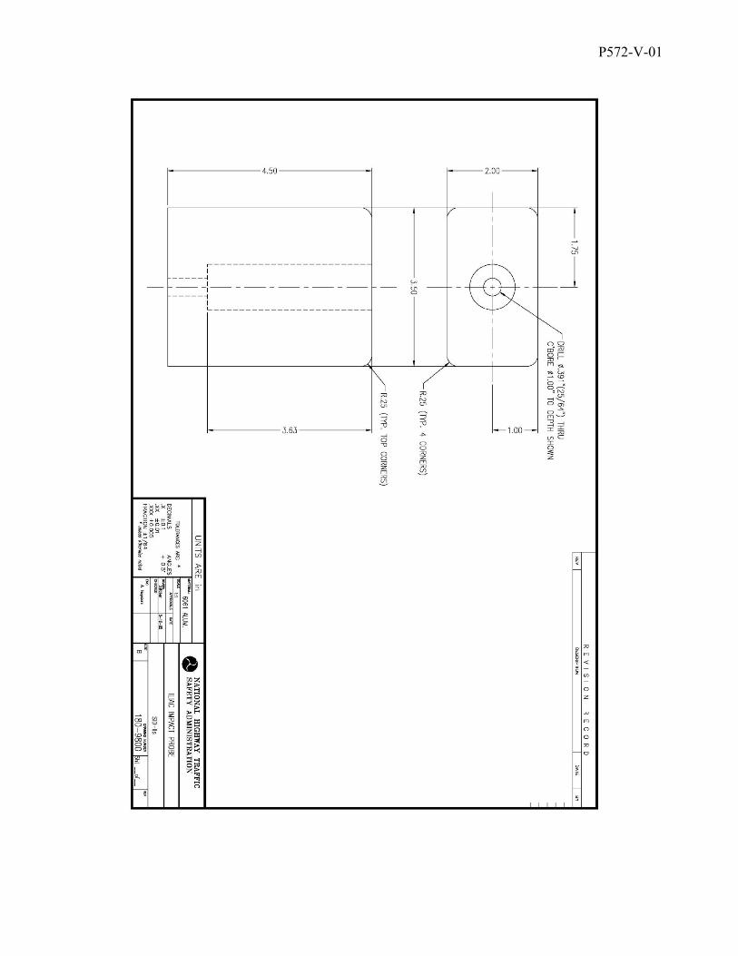
P572-V-01

P572-V-01
ATTACHMENT 3
ILIAC ALIGNMENT TOOL

P572-V-01

P572-V-01
ATTACHMENT 4
Pelvis Plug Quasi Static Certification Procedures Drawing No. 180-4450

cc- - - -
cc
h.E.
. ii- j!;ll riiTfdIHHLL_________
2
-1 ! 1111ii 1111 iI H ItUl I I ifflll.0
cc
(N)p ,
LJ
____
---
Ililhilti I !i'fl -
I
I
dill U-
a
-
I -
-
o I II
!H __
Related Documents