60 Industrial Hydraulics NG 20 Typ VAW 20/NG 32 Typ VAW 32 Sicherheits- und Absperrblöcke Safety and shut-off blocks Blocs de sécurité y 1 Block 2 Übergangsstutzen, Flansch 3 Speicher 4 Druckbegrenzungsventil, plombiert 5 Entlastung manuell 6 Entlastungsventil, elektrisch (wahlweise) 7 Absperrhahn 8 P-Anschluß 9 Meßanschluß yy 1 Block 2 Adapter fitting, Flange 3 Accumulator 4 Pressure-relief valve, sealed with lead 5 Discharge, manual 6 Discharge valve, electric (optional) 7 Shut-off valve 8 P-port 9 Gauge port yyy 1 Bloc 2 Raccord d’adaptation, Bridge 3 Accumulateur 4 Limiteur de pression, plombé 5 Décharge manuelle 6 Valve de décharge, à commande électrique (au choix) 7 Robinet d’isolement 8 Raccord P 9 Prise de pression 1 6 2 5 4 9 8 7 3

Welcome message from author
This document is posted to help you gain knowledge. Please leave a comment to let me know what you think about it! Share it to your friends and learn new things together.
Transcript

60 Industrial Hydraulics
NG 20 Typ VAW 20/NG 32 Typ VAW 32
Sicherheits- und AbsperrblöckeSafety and shut-off blocksBlocs de sécurité
y1 Block2 Übergangsstutzen, Flansch3 Speicher4 Druckbegrenzungsventil, plombiert5 Entlastung manuell6 Entlastungsventil, elektrisch
(wahlweise)7 Absperrhahn8 P-Anschluß9 Meßanschluß
yy1 Block2 Adapter fitting, Flange3 Accumulator4 Pressure-relief valve,
sealed with lead5 Discharge, manual6 Discharge valve, electric (optional)7 Shut-off valve8 P-port9 Gauge port
yyy1 Bloc2 Raccord d’adaptation, Bridge3 Accumulateur4 Limiteur de pression, plombé5 Décharge manuelle6 Valve de décharge, à commande
électrique (au choix)7 Robinet d’isolement8 Raccord P9 Prise de pression
1
6
2 5
4
9
87
3

yVerwendung
Der Bosch Sicherheits- und Absperr-block ist ein Hydraulikelement zur Absperrung und Entlastung; vorzugs-weise für Hydro-Blasenspeicher.Der Block enthält die vorgeschriebe-nen Sicherheits- und Absperrein-richtungen nach DIN 24 552 derDruckbehälterverordnung und denTechnischen Regeln Druckbehälter(TRB 403 und 404).Ein optionales zusätzliches elektrischbetätigtes 2-Wegeventil (stromlos offen) ermöglicht die automatischeEntlastung des Speichers oder Ver-brauchers und damit des hydrauli-schen Systems. Im Sicherheitsfalleoder bei Stillsetzung „Notausfunktion“.Die Verbindung von Anschlußblockund Speicher wird durch einen Über-gangsstutzen bzw. Flansch hergestellt.Der Sicherheits- und Absperrblock be-sitzt folgende Anschlüsse:A – SpeicheranschlußP – Rohrleitungs- oder Flansch-
anschluß (Pumpe)T – TankanschlußM 1 – Prüfmanometeranschluß M 2 – Manometeranschluß
Baumuster-Prüfung
Das Block-Druckbegrenzungsventilwird im Werk durch TÜV-Sachver-ständige geprüft und plombiert.Das Ventil ist mit dem Bauteilkenn-zeichen und einer laufenden Nummerversehen. Eine Bescheinigung überdie Druckeinstellung wird mitgeliefert.
Achtung:Bescheinigung gut aufbewahren.
yyApplication
The Bosch safety and shut-off block isa hydraulic element for the purpose ofshutting off and discharging, pref-erably for use with hydro-pneumaticbladder-type accumulators.The block incorporates safety andshut-off devices as specified to DIN 24 552 of the Pressure VesselsDecree and the Technical Regulationsfor Pressure Vessels (TRB 403 and404).An optional extra electrically operated2-way directional control valve (openwithout flow) enables the accumulatoror consuming device – and thereforethe hydraulic system – to be automati-cally relieved of pressure. This occurswhen the safety elements are neededor in the event of shutdown, “Emer-gency stop function”.The manifold and accumulator areconnected via an adapter fitting orflange.The safety and shut-off block featuresthe following connections:A – Accumulator connectionP – Pipeline or flange connection
(pump)T – Tank connectionM 1 – Test gauge connectionM 2 – Pressure gauge connection
Approval
The pressure-relief valve block is tested and sealed by TÜV representa-tives. The valve is marked with thecode and a serial number. Certificationof the pressure setting is suppliedwith the valve.
Important:Keep the certificate in a safe place.
yyyUtilisation
Le bloc de sécurité Bosch est un élément hydraulique d’isolement et dedécharge, particulièrement bien adapté aux accumulateurs hydrauli-ques à vessie. Le bloc contient les dispositifs de sécurité et d’isolement prescrits selonDIN 24552, dans l’«ordonnance rela-tive aux réservoirs sous pression» etles «règles techniques relatives aux réservoirs sous pression» (TRB 403 et404).Un distributeur optionnel supplémen-taire, à deux voies et à commandeélectrique (ouvert sans courant), permet une décharge automatique del’accumulateur ou du consommateuret donc du système hydraulique. Encas de mise en jeu du bloc de sécuritéou en cas d’arrêt «fonction d’arrêtd’urgence».La liaison entre le bloc et l’accumula-teur est assurée par un raccord d’adaptation ou une bride. Le bloc desécurité possède les raccords suivants:A – raccord de l’accumulateurP – raccord pour tuyauterie ou
raccord à bride (pompe)T – raccord du réservoirM 1 – raccord du manomètre de
contrôleM 2 – raccord du manomètre
Homologation
Le limiteur de pression du bloc estcontrôlé et plombé à l’usine par un expert du TÜV. La valve est marquéeavec ses références et numérotée. Uncertificat indiquant le réglage de lapression est fourni avec la valve.
Attention:Conserver soigneusement le certificat.
Industrial Hydraulics 61

62 Industrial Hydraulics
SachmerkmalleisteCharacteristics barRangee de codification de caractéristiques
0 532 VAW / 20 / 1 / FPM / 330 / 150 / D / Z / 03 / G / 24 / 00 / A 1
1 2 3 4 5 6 7 8 9
y1 Speichersicherheitsblock für
wechselbare, „baumustergeprüfte“DBV-Patrone
2 Bauart (NG 20)
3 Anzahl der eingebauten DBV-Patronen
4 Dichtungswerkstoff FPM; NBR
5 Einstelldruck/Abblaseleistung
6 DBV VerstellbetätigungD = mit HandradK = mit Spindel, durch Kappe
abgedeckt
7 LeitungsanschlußZ = zölligM = metrischF = Flanschanschluß
8 Entlastungsventil00 = ohne Entlastungsventil01 = 2/2 Ventilpatrone
stromlos offen manuell betätigt
03 = 2/2 Magnetventilpatronestromlos offen
04 = 2/2 Magnetventilpatronestromlos geschlossen
Spannungsart G = GleichstromW = Wechselstrom
Spannung/Frequenz (220 V/50 Hz)
9 KennzahlA = Generation1 = StandardausführungS = Sonderausführung
yy1 Accumulator safety block for re-
placeable “type-approved” pres-sure-relief valve cartridge
2 Design (NG 20)
2 Number of installed pressure-reliefvalve cartridges
4 Sealing material FPM; NBR
5 Setting pressure/discharge power
6 Pressure-relief valve adjustmentD = with handwheelK = with spindle, covered by cap
7 Pipe connectionZ = imperialM = metricF = flange connection
8 Discharge valve00 = without discharge valve01 = 2/2 valve cartridge
open without flowmanually operated
03 = 2/2 solenoid valve cartridgeopen without flow
04 = 2/2 solenoid valve cartridgeclosed without flow
Voltage type G = direct currentW = alternating
currentVoltage/frequency (220V/50 Hz)
9 CodeA = Generation1 = Standard versionS = Non-standard version
yyy1 Bloc de sécurité pour limiteur de
pression type cartouche inter-changeable «avec homologation»
2 Construction (NG 20)
2 Nombre des limiteurs de pressiontype cartouche montés
4 Matière du joint FPM; NBR
5 Pression de réglage/puissanced’évacuation
6 Commande de réglage du limiteurde pressionD = par volantK = par broche, recouverte par un
capuchon
7 Raccord pour tuyauterieZ = en poucesM = métriqueF = raccord à bride
8 Valve de décharge00 = sans valve de décharge01 = valve cartouche 2/2
ouverte sans courantà commande manuelle
03 = électrovanne cartouche 2/2ouverte sans courant
04 = électrovanne cartouche 2/2fermée sans courant
Type de tension G = courant continu
W = courant alternatif
Tension/fréquence (220 V/50 Hz)
9 IndiceA = génération1 = version standardS = version spéciale
ySpeicher-, Sicherheits- und Absperrblock NG 20Block für wechselbare „baumusterge-prüfte“ DBV-Patrone.
yyAccumulator safety and shut-offblock NG 20Block for replaceable “type-approved”pressure-relief valve cartridge.
yyyBloc de sécurité NG 20Bloc pour limiteurs de pression typecartouche interchangeables «avec homologation».
Industrial Hydraulics 63
Symb. 1 Symb. 2
Symb. 4 Symb. 8
Symb. 3
0 532 VAW / 20 / 1 / FPM / 330 / 150 / D / Z / 03 / G / 24 / 00 / A 1
Symbol FPM p GNBR [bar] [l/min] V/Hz [kg] «
1 – – – 5,1 0 532 015 1202 – – 24/00 5,6 0 532 015 1218 – – manuell 5,7 0 532 015 1393 170 150 – 5,5 0 532 015 1234 170 150 24/00 6,0 0 532 015 1223 100 100 – 5,5 0 532 015 1254 100 100 24/00 6,0 0 532 015 1243 140 100 – 5,5 0 532 015 1273 160 100 – 5,5 0 532 015 1294 FPM 160 100 D Z 24/00 6,0 0 532 015 1263 211 100 – 5,5 0 532 015 1314 211 100 24/00 6,0 0 532 015 1283 250 130 – 5,5 0 532 015 1334 250 130 24/00 6,0 0 532 015 1303 280 130 – 5,5 0 532 015 1374 280 130 24/00 6,0 0 532 015 1343 330 150 – 5,5 0 532 015 1354 330 150 24/00 6,0 0 532 015 132
Anschlüsse A: M 33x2 M 1: G 1/2 verschlossen / plugged / obturéPorts P: G1 M 2: G 1/4 verschlossen / plugged / obturéRaccords T: G 1/2
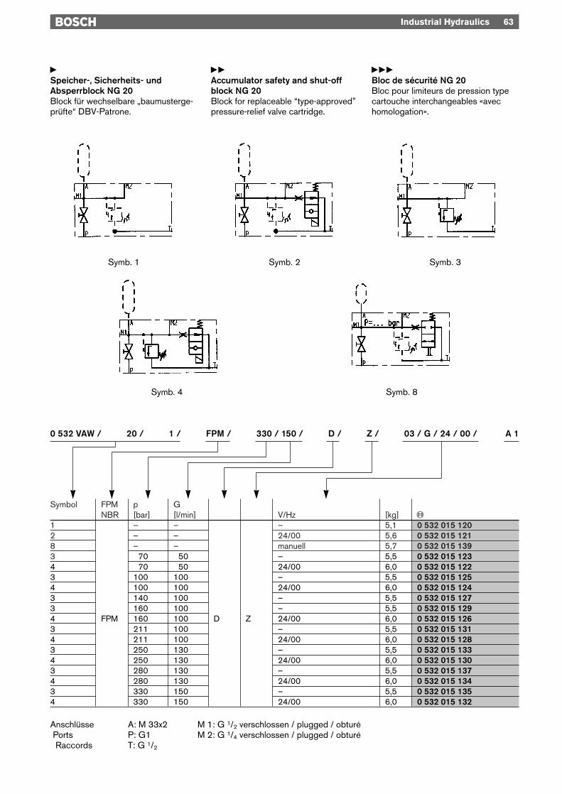
ySpeicher-, Sicherheits- und Absperrblock NG 32Block für 1 Stück wechselbare „baumustergeprüfte“ DBV-Patrone.
yyAccumulator safety and shut-offblock NG 32Block for one replaceable “type-ap-proved” pressure-relief valve cartridge.
yyyBloc de sécurité NG 32Bloc pour un seul limiteur de pressiontype cartouche interchangeable «avechomologation».
64 Industrial Hydraulics
Symb. 1 Symb. 2
Symb. 4 Symb. 8
Symb. 3
0 532 VAW / 32 / 1 / FPM / 330 / 150 / D / Z / 03 / G / 24 / 00 / A 1
Symbol FPM p GNBR [bar] [l/min] V/Hz [kg] «
2 – – 24/00 14,3 0 532 016 0501 – – – 13,8 0 532 016 0518 – – manuell 14,4 0 532 016 0614 160 100 24/00 14,7 0 532 016 0543 FPM 211 100 D Z – 14,2 0 532 016 0534 211 100 24/00 14,7 0 532 016 0563 330 150 – 14,2 0 532 016 0554 330 150 24/00 14,7 0 532 016 0584 330 150 F* 24/00 13,9 0 532 016 060
Anschlüsse A: Flansch / Flange / Bride M 1: G 1/2 verschlossen / plugged / obturéPorts P: G 11/2 M 2: G 1/4 verschlossen / plugged / obturéRaccords * P: Flansch / Flange / Bride
T: G 1

ySpeicher-, Sicherheits- und Absperrblock NG 32Block für 2 Stück wechselbare „baumustergeprüfte“ DBV-Patrone.
yyAccumulator safety and shut-offblock NG 32Block for two replaceable “type-approved” pressure-relief valve car-tridges.
yyyBloc de sécurité NG 32Bloc pour deux limiteurs de pressiontype cartouche interchangeables«avec homologation».
Industrial Hydraulics 65
Symb. 7 Symb. 9
Symb. 5 Symb. 6
0 532 VAW / 32 / 2 / FPM / 330 / 300 / DK / Z / 03 / G / 24 / 00 / A 1
Symbol FPM p GNBR [bar] [l/min] V/Hz [kg] «
5 FPM – – DK Z 24/00 14,2 0 532 016 0529 – – Z manuell 14,3 0 532 016 0636 280 260 Z – 14,7 0 532 016 0577 211 200 F* 24/00 14,4 0 532 016 0707 250 260 F* 24/00 14,4 0 532 016 072
Anschlüsse A: Flansch / Flange / Bride M 1: G 1/2 verschlossen / plugged / obturéPorts P: G 11/2 M 2: G 1/4 verschlossen / plugged / obturéRaccords * P: Flansch / Flange / Bride
T: G 1
66 Industrial Hydraulics
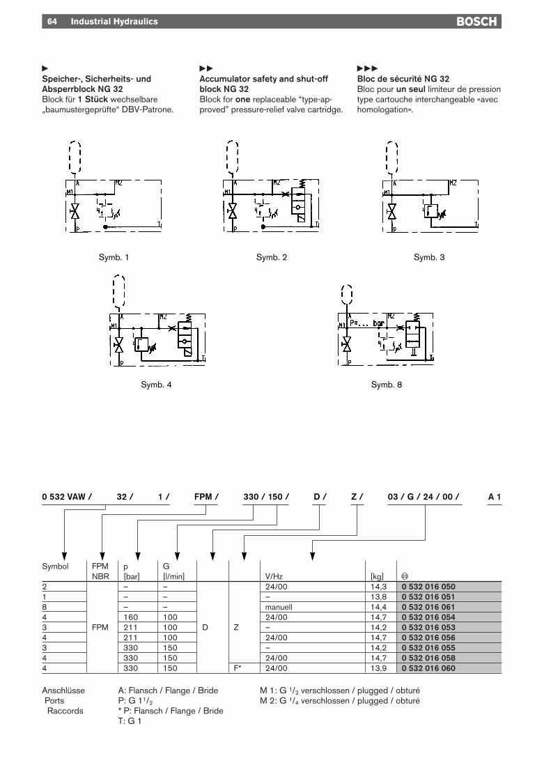
yKenngrößenBauart Sicherheitsventil Sitzventil mit Dämpfung
Absperrhahn Kugelhahnelektr. Entlastung Sitzventil
Anschlußart Rohranschluß bzw. FlanschEinbaulage Anschluß A oder elektrische Entlastung obenUmgebungstemperatur –15 °C … +80 °C elektrische Entlastung +40 °Cmax. Betriebsdruck 350 barAbblasestrom G [l/min] siehe Tabellen Seite 63 … 65und pNom barDruckflüssigkeit F Mineralöle nach DIN/ISO
und schwer entflammbare Druckflüssigkeitennach VDMA 24 317/24 320
Betriebstemperaturbereich –15 °C … +80 °CViskositätsbereich 12 … 380 mm2/s∆p-Q Kennlinien siehe Seite 67 … 68Elektrische Entlastung U = 24 V/DC 1,04 A; 105 DC (für 115 V/60 Hz, AC gleichgerichtet)
p20 = 26 W, 100 % EDIP 65, Stecker DIN 43 650
yyCharacteristicsConstruction Safety valve Damped poppet valve
Shut-off valve Ball valveElectr. discharge Poppet valve
Type of connection Pipe connection/flangeInstallation position Port A or electrical discharge aboveAmbient temperature –15 °C … +80 °C electrical discharge +40 °Cmax. working pressure 350 barDischarge flow rate G [l/min] see tables, pages 63 … 65and pNom barPressure fluid F Mineral oils as per DIN/ISO
and flame-retardant pressure fluidsas per VDMA 24 317/24 320
Working temperature range –15 °C … +80 °CViscosity range 12 … 380 mm2/s∆p-Q characteristics see page 67 … 68Electrical discharge U = 24 V/DC 1,04 A; 105 DC (for 115 V/60 Hz, AC rectified)
p20 = 26 W, 100 % c.d.f.IP 65, connector DIN 43 650
yyyCaractéristiquesConstruction de la valve de sécurité à clapet avec amortissement
du robinet d’isolement robinet sphériquede l’électro-valve de type à clapetdécharge
Raccordement raccord par tuyau ou bridePosition de montage orifice A ou électrovalve de décharge en hautTempérature ambiante –15 °C … +80 °C, électro valve de décharge +40 °CPression de service max. 350 barDébit évacué G [l/min] voir tableaux pages 63 … 65et pNom barFluide hydraulique F huiles minérales selon DIN/ISO
et fluides difficilement inflammablesselon VDMA 24 317/24 320
Plage de température de service –15 °C … +80 °CPlage de viscosité 12 … 380 mm2/sCourbes ∆p-Q voir pages 67 … 68Electrovalve de décharge U = 24 V/DC 1,04 A; 105 DC (pour 115 V/60 Hz, C.A. redressé)
p20 = 26 W, 100 % F.M.IP 65, connecteur DIN 43 650
Industrial Hydraulics 67
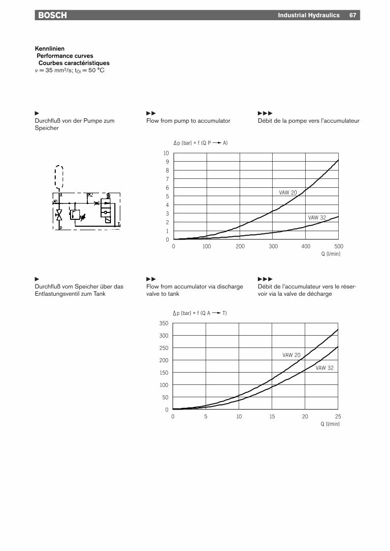
KennlinienPerformance curvesCourbes caractéristiques
n = 35 mm2/s; tÖl = 50 °C
yDurchfluß von der Pumpe zum Speicher
yyFlow from pump to accumulator
yyyDébit de la pompe vers l’accumulateur
yDurchfluß vom Speicher über das Entlastungsventil zum Tank
yyFlow from accumulator via dischargevalve to tank
yyyDébit de l’accumulateur vers le réser-voir via la valve de décharge

68 Industrial Hydraulics
KennlinienPerformance curvesCourbes caractéristiques
n = 35 mm2/s; tÖl = 50 °C
yDurchfluß vom Speicher über dasDruckbegrenzungsventil zum Tank
yyFlow from accumulator via pressure-relief valve to tank
yyyDébit de l’accumulateur vers le réser-voir via le limiteur de pression

Industrial Hydraulics 69
PlombierungLead sealPlombage
Manuelle EntlastungManual dischargeDécharge manuelle
Übergangsstutzen (nicht im Lieferumfang)Adapter (not in scope of delivery included)Raccord (non compris dans la fourniture)
Abmessungen NG 20 (VAW 20)DimensionsCotes d’encombrement

70 Industrial Hydraulics
Abmessungen NG 20 (VAW 20)DimensionsCotes d’encombrement
Manuelle EntlastungManual dischargeDécharge manuelle
Stecker beigelegtPlug connector includetConnecteur inclus
PlombierungLead sealPlombage
Übergangsstutzen (nicht im Lieferumfang)Adapter (not in scope of delivery included)Raccord (non compris dans la fourniture)

Industrial Hydraulics 71
Abmessungen NG 20 (VAW 20)DimensionsCotes d’encombrement
Manuelle EntlastungManual dischargeDécharge manuelle
geschlossenshutfermè
offenopenouvert
PlombierungLead sealPlombage
Übergangsstutzen (nicht im Lieferumfang)Adapter (not in scope of delivery included)Raccord (non compris dans la fourniture)

72 Industrial Hydraulics
Abmessungen NG 32 (VAW 32) RohrleitungsanschlußDimensions Pipe connectionCotes d’encombrement Raccord pour tuyauterie
Übergangsstutzen M 50x1,5 « 1 535 702 000AdapterRaccord G 2 « 1 535 702 001
(nicht im Lieferumfang)(not in scope of delivery included)(non compris dans la fourniture) 4x f M 16x50 DIN 912 10,9 « 2 910 151 442 incl.
u = 240+20 Nm
Manuelle EntlastungManual dischargeDécharge manuelle
PlombiermöglichkeitSealing possibilityPossibilité de plombage

Industrial Hydraulics 73
Abmessungen NG 32 (VAW 32) RohrleitungsanschlußDimensions Pipe connectionCotes d’encombrement Raccord pour tuyauterie
Steckanschluß DIN 43650 AEquipment connectorConnecteur
PlombiermöglichkeitSealing possibilityPossibilité de plombage
Manuelle EntlastungManual dischargeDécharge manuelle
Übergangsstutzen M 50x1,5 « 1 535 702 000AdapterRaccord G 2 « 1 535 702 001
(nicht im Lieferumfang)(not in scope of delivery included)(non compris dans la fourniture)
4x f M 16x50 DIN 912 10,9 « 2 910 151 442 incl.u = 240+20 Nm

74 Industrial Hydraulics
Abmessungen NG 32 (VAW 32) FlanschanschlußDimensions Flange connectionCotes d’encombrement Raccord à bride
Gegenflansch nicht im LieferumfangCounterflange not in scope of delivery includedContre-bridge non compris dans la fourniture
tiefdepthprof.
Steckanschluß DIN 43650 AEquipment connectorConnecteur d’apres
Übergangsstutzen M 50x1,5 « 1 535 702 000AdapterRaccord G 2 « 1 535 702 001
(nicht im Lieferumfang)(not in scope of delivery included)(non compris dans la fourniture)
4x f M 16x50 DIN 912 10,9 « 2 910 151 442 incl.u = 240+20 Nm
Ansicht AView AVeu A

Industrial Hydraulics 75
PlombiermöglichkeitSealing possibilityPossibilité de plombage
Manuelle EntlastungManual dischargeDécharge manuelle
geschlossenshutfermé
offenopenouvert
Übergangsstutzen M 50x1,5 « 1 535 702 000AdapterRaccord G 2 « 1 535 702 001
(nicht im Lieferumfang)(not in scope of delivery included)(non compris dans la fourniture)
4x f M 16x50 DIN 912 10,9 « 2 910 151 442 incl.u = 240+20 Nm
Abmessungen NG 32 (VAW 32) RohrleitungsanschlußDimensions Pipe connectionCotes d’encombrement Raccord pour tuyauterie

76 Industrial Hydraulics
Abmessungen NG 32 (VAW 32) RohrleitungsanschlußDimensions Pipe connectionCotes d’encombrement Raccord pour tuyauterie
PlombiermöglichkeitSealing possibilityPossibilité de plombage
PlombiermöglichkeitSealing possibilityPossibilité de plombage
Steckanschluß DIN 43650 AEquipment connectorConnecteur
Manuelle EntlastungManual dischargeDécharge manuelle
Übergangsstutzen M 50x1,5 « 1 535 702 000AdapterRaccord G 2 « 1 535 702 001
(nicht im Lieferumfang)(not in scope of delivery included)(non compris dans la fourniture)
4x f M 16x50 DIN 912 10,9 « 2 910 151 442 incl.u = 240+20 Nm
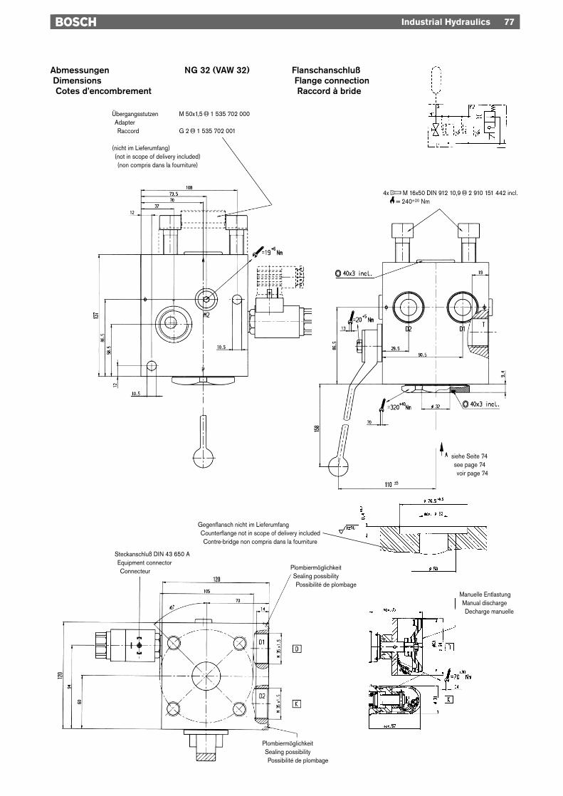
Industrial Hydraulics 77
Abmessungen NG 32 (VAW 32) FlanschanschlußDimensions Flange connectionCotes d’encombrement Raccord à bride
Manuelle EntlastungManual dischargeDecharge manuelle
siehe Seite 74see page 74voir page 74
PlombiermöglichkeitSealing possibilityPossibilité de plombage
Manuelle EntlastungManual dischargeDécharge manuelle
Übergangsstutzen M 50x1,5 « 1 535 702 000AdapterRaccord G 2 « 1 535 702 001
(nicht im Lieferumfang)(not in scope of delivery included)(non compris dans la fourniture)
4x f M 16x50 DIN 912 10,9 « 2 910 151 442 incl.u = 240+20 Nm
PlombiermöglichkeitSealing possibilityPossibilité de plombage
Steckanschluß DIN 43 650 AEquipment connectorConnecteur
Gegenflansch nicht im LieferumfangCounterflange not in scope of delivery includedContre-bridge non compris dans la fourniture
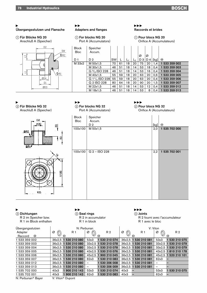
yÜbergangsstutzen und Flansche
1 Für Blöcke NG 20Anschluß A (Speicher)
yyAdapters and flanges
1 For blocks NG 20Port A (Accumulators)
yyyRaccords et brides
1 Pour blocs NG 20Orifice A (Accumulateurs)
78 Industrial Hydraulics
Block SpeicherBloc Accum.
Ø 3 Ø 3D 1 D 2 SW L L1 L2 D 3 D 4 [kg] «M 33x2 M 50x1,5 70 61 18 20 75 20 1,4 1 533 359 002
M 30x1,5 46 51 18 14 53 18 0,4 1 533 359 003G 3/4 ISO 228 46 51 18 14 53 16 0,4 1 533 359 004M 40x1,5 55 59 18 20 63 20 0,6 1 533 359 005G 11/4 ISO 228 55 59 18 20 63 20 0,4 1 533 359 006G 2 ISO 228 80 64 18 20 90 20 1,5 1 533 359 007M 22x1,5 46 51 18 14 53 12 0,4 1 533 359 012M 18x1,5 46 51 18 14 53 18 0,4 1 533 359 013
Block SpeicherBloc Accum.
D 2 [kg] «100x100 M 50x1,5 2,0 1 535 702 000
100x100 G 2 – ISO 228 2,2 1 535 702 001
y2 Für Blöcke NG 32
Anschluß A (Speicher)
yy2 For blocks NG 32
Port A (Accumulators)
yyy2 Pour blocs NG 32
Orifice A (Accumulateurs)
y3 Dichtungen
R 2 im Speicher bzw.R 1 im Block enthalten
yy3 Seal rings
R 2 in accumulatorR 1 in block
yyy3 Joints
R 2 fourni avec l’accumulateurR 1 avec le bloc
Übergangsstutzen N: Perbunan V: VitonAdapter Ø R 1 Ø R 2 Ø R 1 Ø R 2Raccord « « « « «
1 533 359 002 36x2,5 1 530 210 080 53x3 1 530 210 074 36x2,5 1 530 210 081 53x3 1 530 210 0751 533 359 003 36x2,5 1 530 210 080 33x2,5 1 530 210 078 36x2,5 1 530 210 081 33x2,5 1 530 210 0791 533 359 004 36x2,5 1 530 210 080 33x2,5 1 530 210 078 36x2,5 1 530 210 081 33x2,5 1 530 210 0791 533 359 005 36x2,5 1 530 210 080 43x2,5 1 530 210 076 36x2,5 1 530 210 081 43x2,5 1 810 210 1781 533 359 006 36x2,5 1 530 210 080 45x2,5 1 900 210 045 36x2,5 1 530 210 081 45x2,5 1 520 210 1011 533 359 007 36x2,5 1 530 210 080 62x3 1 530 210 083 36x2,5 1 530 210 081 62x3 –1 533 359 012 36x2,5 1 530 210 080 – 1 530 206 008 36x2,5 1 530 210 081 – –1 533 359 013 36x2,5 1 530 210 080 – 1 530 206 009 36x2,5 1 530 210 081 – –1 535 702 000 40x3 1 900 210 143 53x3 1 530 210 074 40x3 – 53x3 1 530 210 0751 535 702 001 40x3 1 900 210 143 62x3 1 530 210 083 40x3 – 62x3 –N: Perbunan® Bayer V: Viton® Dupont
w w w w
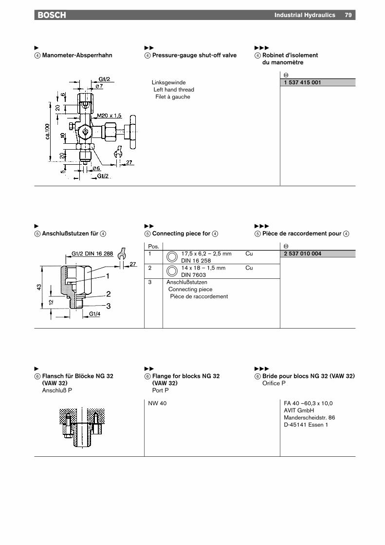
y4 Manometer-Absperrhahn
yy4 Pressure-gauge shut-off valve
yyy4 Robinet d’isolement
du manomètre
Industrial Hydraulics 79
y5 Anschlußstutzen für 4
yy5 Connecting piece for 4
yyy5 Pièce de raccordement pour 4
«Linksgewinde 1 537 415 001Left hand threadFilet à gauche
Pos. «1 17,5 x 6,2 – 2,5 mm Cu 2 537 010 004
DIN 16 2582 14 x 18 – 1,5 mm Cu
DIN 76033 Anschlußstutzen
Connecting piecePièce de raccordement
tt
y6 Flansch für Blöcke NG 32
(VAW 32)Anschluß P
yy6 Flange for blocks NG 32
(VAW 32)Port P
yyy6 Bride pour blocs NG 32 (VAW 32)
Orifice P
NW 40 FA 40 –60,3 x 10,0AVIT GmbHManderscheidstr. 86D-45141 Essen 1
Related Documents