Actuators www.norgren.com/usa ACT-2 Impact dampening seals Adjustable captive cushion needle Ecology cylinders meet OSHA noise standards Constructed of the finest materials Technical data Medium: Filtered compressed air to 250 PSI Petroleum based hydraulic fluid to 400 PSI* Operating temperature: Series A & J -20°F to 200°F with Viton Seals -20˚F to 400˚F Operating Pressure: 250 PSIG Air, 400 PSIG Hydraulic* non-shock. NOTE: EA and EJ max pressure rating: 150 psi. Bore Sizes: 1-1/2", 2", 2-1/2", 3-1/4", 4", 5", 6", 7", 8", 10"*, 12"* Lubrication: None required Norgren Air Cylinders are rated for “no lube added” service. All internal components are lubricated at time of assembly with a Teflon® based grease. Materials Head and End Caps: (A and EA Series) black anodized aluminum alloy (J and EJ Series) precision machined steel* Tube: A & EA Series 1/2" to 8" J & EJ Series 1-1/2" to 2-1/2" Aluminum alloy, clear anodized O.D., hard coat anodized I.D. J & EJ Series 3-1/4" to 12" has steel tube, with hard chrome plated I.D. Piston: A & EA series: machined high- strength aluminum alloy. J & EJ series: steel Piston rod: hard chrome plated steel Rod Bearing: oil impregnated sintered iron Seals: nitrile rod seal, urethane rod wiper, nitrile piston seals, nitrile tube end seals Tie Rods: high-tensile strength steel * J and EJ series only NFPA Aluminum & Steel Cylinders NFPA Series A Aluminum & J Steel Cylinders 1-1/2 to 12 inch bore size Ultra Cushion ® Seals: Advanced design features a unique, one-piece, compound seal of nitrile* captured within a precision machined groove. Linear and radial “float” of the cushion seals eliminates misalignment. Ultra Cushions provide exceptionally fast “out of cushion” stroke reversal. (Head and Cap Cushions are optional.) *Nitrile seals on the 5/8" & 1" rod diameter. For rod sizes 1-3/4" and larger, urethane seals are standard. Adjustable Captive Cushion Needle: A one- piece, precision threaded brass cushion adjustment screw with a threaded steel capture ring. It provides safe and precise cushion adjustment. Wear Ring: Reinforced Teflon ® compounded with polyphenylene sulfide provides supreme wear and excellent bearing support. 5 Rod Seal: Nitrile lip type seal is pressure energized and wear compensating for durability and long life. 6 1 Wiper Seal: Lip-type urethane wiper seal keeps contaminates from getting into cylinder by aggressively wiping foreign materials from the piston rod, enhancing the rod seal life. 3 4 1 2 3 3 5 4 O-Ring Tube Seal: Nitrile is standard. (Viton is optional.) 2 6

Welcome message from author
This document is posted to help you gain knowledge. Please leave a comment to let me know what you think about it! Share it to your friends and learn new things together.
Transcript

Actuators
www.norgren.com/usaACT-2
Impact dampening sealsAdjustable captive cushion needleEcology cylinders meet OSHAnoise standardsConstructed of the finest materialsTechnical dataMedium:Filtered compressed air to 250 PSIPetroleum based hydraulic fluid to400 PSI*Operating temperature:Series A & J -20°F to 200°F with Viton Seals -20˚F to 400˚FOperating Pressure:250 PSIG Air, 400 PSIG Hydraulic*non-shock.NOTE: EA and EJ max pressurerating: 150 psi. Bore Sizes: 1-1/2", 2", 2-1/2", 3-1/4", 4", 5", 6", 7", 8", 10"*, 12"*Lubrication:None requiredNorgren Air Cylinders are rated for“no lube added” service. All internalcomponents are lubricated at time ofassembly with a Teflon® basedgrease.Materials Head and End Caps: (A and EA Series)black anodized aluminum alloy(J and EJ Series)precision machined steel*Tube: A & EA Series 1/2" to 8"J & EJ Series 1-1/2" to 2-1/2"Aluminum alloy, clear anodized O.D.,hard coat anodized I.D.J & EJ Series 3-1/4" to 12" has steeltube, with hard chrome plated I.D.Piston: A & EA series: machined high-strength aluminum alloy. J & EJ series: steelPiston rod: hard chrome plated steelRod Bearing: oil impregnatedsintered ironSeals: nitrile rod seal, urethane rodwiper, nitrile piston seals, nitrile tubeend sealsTie Rods: high-tensile strength steel* J and EJ series only
NFPA Aluminum & Steel CylindersNFPA Series A Aluminum & J Steel Cylinders1-1/2 to 12 inch bore size
Ultra Cushion® Seals: Advanced designfeatures a unique, one-piece, compound seal ofnitrile* captured within a precision machinedgroove. Linear and radial “float” of the cushionseals eliminates misalignment. Ultra Cushionsprovide exceptionally fast “out of cushion” strokereversal. (Head and Cap Cushions are optional.)*Nitrile seals on the 5/8" & 1" rod diameter. For rod sizes 1-3/4" and larger, urethane seals are standard.
Adjustable Captive Cushion Needle: A one-piece, precision threaded brass cushionadjustment screw with a threaded steel capturering. It provides safe and precise cushionadjustment.
Wear Ring: Reinforced Teflon®
compounded with polyphenylene sulfide providessupreme wear and excellent bearing support.
5
Rod Seal: Nitrile lip type seal is pressureenergized and wear compensating for durabilityand long life.
6
1
Wiper Seal: Lip-type urethane wiper seal keeps contaminates from getting into cylinder by aggressively wiping foreign materials from thepiston rod, enhancing the rod seal life.
3
4
1 2
3
35
4
O-Ring Tube Seal: Nitrile is standard.(Viton is optional.)
2
6

ACT-3
NFPA Aluminum & Steel Cylinders
Port and CushionAdjustment Positions (As viewed from rod end: Portstandard position 1, CushionAdjustment standard position 2.)NOTE: A Port and a Cushion Adjustmentcannot be in the same position.
1
3
4 2
Cylinder Order Information
EJ 01 7 7 A 1 - HR–L(14)–MS–P(1/4) V - 2" x 6"
SeriesSeries A Cylinder (Aluminum) ASeries A Double Rod End Cylinder DASeries EA Cylinder EASeries EA Double Rod End Cylinder EDASeries J Cylinder (Steel) JSeries J Double Rod End Cylinder DJSeries EJ Cylinder EJSeries EJ Double Rod End Cylinder EDJ
Mounting OptionsSide Tapped (MS4) 01Head Rectangular Flange (MF1) 03Head Square (ME3) – 7" & 8" Bores 03Cap Rectangular Flange (MF2) 04Cap Square (ME4) – 7" & 8" Bores 04Basic Cylinder No Mounting (MX0 05Both Ends (4) Tie Rods Ext. (MX1) 06Both Ends (2) Tie Rods Ext. (MX4) 6BCap Tie Rods Ext. (MX2) 6CHead Tie Rods Ext. (MX3) 6RRemovable Head Trunnion (MT1) - A & EA 7RHead Trunnion (MT1) - J & EJ 07Removable Cap Trunnion (MT2) - A & EA 8RCap Trunnion (MT2) - J & EJ 08Side Lugs (MS2) 09Center Trunnion (MT4) 10Side End Angles (MS1) 11Cap Fixed Clevis (MP1) 12Side End Lugs (MS7) 15Sleeve Nut Construction (Universal) 16Head Square Flange (MF5) 20Cap Square Flange (MF6) 21Detachable Cap Clevis (MP2) 22Cap Fixed Eye (MP3) 32Detachable Cap Eye (MP4) 42Spherical Bearing 52Base Bar (Not NFPA A & EA Only) 60
Additional Options – order alphabetically – More on page ??Case Hardened (50 Rc) HRPort Location position 1 standard: L(Head Cap)(specify position 1 thru 4 for head and/or cap) L(_ _)Rod Lock (passive) LELow Friction LFStroke Adjustment AMetal Rod Scraper MSCushion Adjust Screw Location position 2 standard:N(Head Cap) (specify position 1 thru 4 for head and/or cap) N(_ _)Non-Standard Port Sizes: [specify port size for P(_H)head only, P(_C) cap only, or P(_) both head & cap] *P(_)Magnetic Piston – includes aluminum tube option - J & EJ PSRod Stud RSRod Extensions (specify length of additional rod extension) RXStainless Steel tie-rods S303 Stainless Steel (Hard Chrome Plated) SSStainless Steel bushing SBStop Tube (Rod End) (specify stop tube length) ST(_R)Special Rod Threads (specify rod thread) TThread Extensions (specify length of thread extension) TXViton® Seals V
Cushion in Head None 3Non-Adjustable Cushion †5Adjustable Cushion (Position 2) 7Decel Cushion 9
Bore and Stroke (write out )
† Standard with EA & EJ
Piston Rod Threads Type Dim refSmall Male (Solid) (std) 1 KKIntermediate Thread Male (Solid) 2 CCFemale 3 KKFull Thread Male (Solid) 6 FFPlain Rod End 7 –
Cushion in Cap None 3Non-Adjustable Cushion †5Adjustable Cushion (Position 2) 7Decel Cushion 9
† Standard with EA & EJ
Notes+ Head cushion not availale on these bore and piston rodcombinations.Additional rod sizes available upon request.Dimensions for thread sizes available on following pages.
* 1-1/2", 2", 2-1/2" bore cylinders have 3/8" NPT Standard, 1/2" NPT oversize. 3-1/4", 4", 5" bore cylinders have 1/2" NPT Standard, 3/4" NPT oversize.
Cyl rod rod dia.bore ltr. (mm)1-1/2 A 5/8
B+ 1
2 A 5/8B 1C+ 1-3/8A 5/8
2-1/2 B 1C 1-3/8D+ 1-3/4B 1
3-1/4 C 1-3/8D 1-3/4E 2B 1C 1-3/8
4 D 1-3/4E 2F 2-1/2B 1C 1-3/8
5 D 1-3/4E 2F 2-1/2
Cyl rod rod dia.bore ltr. (mm)
C 1-3/8
6 D 1-3/4E 2F 2-1/2C 1-3/8
7 D 1-3/4E 2F 2-1/2C 1-3/8
8 D 1-3/4E 2F 2-1/2D 1-3/4
10 E 2F 2-1/2
12 E 2F 2-1/2
Actuators
www.norgren.com/usaACT-4
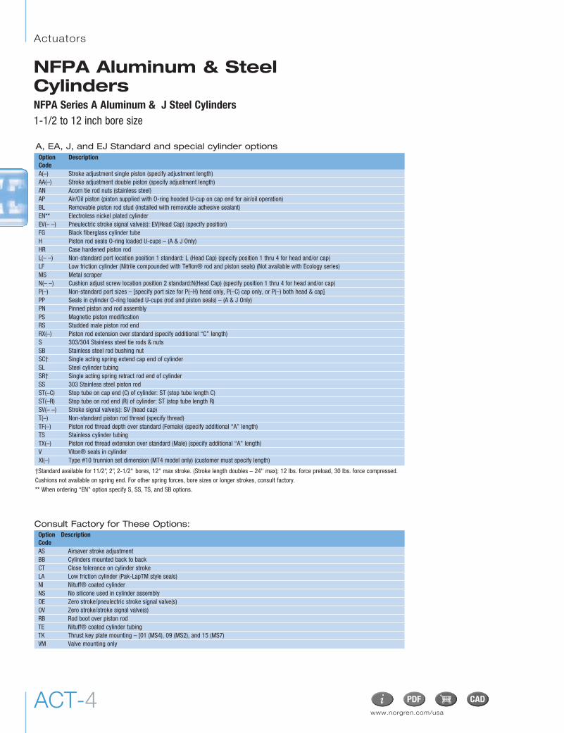
Option DescriptionCodeA(–) Stroke adjustment single piston (specify adjustment length)AA(–) Stroke adjustment double piston (specify adjustment length)AN Acorn tie rod nuts (stainless steel)AP Air/Oil piston (piston supplied with O-ring hooded U-cup on cap end for air/oil operation)BL Removable piston rod stud (installed with removable adhesive sealant)EN** Electroless nickel plated cylinderEV(– –) Pneulectric stroke signal valve(s): EV(Head Cap) (specify position)FG Black fiberglass cylinder tubeH Piston rod seals O-ring loaded U-cups – (A & J Only)HR Case hardened piston rodL(– –) Non-standard port location position 1 standard: L (Head Cap) (specify position 1 thru 4 for head and/or cap)LF Low friction cylinder (Nitrile compounded with Teflon® rod and piston seals) (Not available with Ecology series)MS Metal scraperN(– –) Cushion adjust screw location position 2 standard:N(Head Cap) (specify position 1 thru 4 for head and/or cap)P(–) Non-standard port sizes – [specify port size for P(–H) head only, P(–C) cap only, or P(–) both head & cap]PP Seals in cylinder O-ring loaded U-cups (rod and piston seals) – (A & J Only)PN Pinned piston and rod assemblyPS Magnetic piston modificationRS Studded male piston rod endRX(–) Piston rod extension over standard (specify additional “C” length)S 303/304 Stainless steel tie rods & nutsSB Stainless steel rod bushing nutSC† Single acting spring extend cap end of cylinderSL Steel cylinder tubingSR† Single acting spring retract rod end of cylinder SS 303 Stainless steel piston rodST(–C) Stop tube on cap end (C) of cylinder: ST (stop tube length C)ST(–R) Stop tube on rod end (R) of cylinder: ST (stop tube length R)SV(– –) Stroke signal valve(s): SV (head cap)T(–) Non-standard piston rod thread (specify thread)TF(–) Piston rod thread depth over standard (Female) (specify additional “A” length)TS Stainless cylinder tubingTX(–) Piston rod thread extension over standard (Male) (specify additional “A” length)V Viton® seals in cylinderXI(–) Type #10 trunnion set dimension (MT4 model only) (customer must specify length)
Consult Factory for These Options:
†Standard available for 11/2", 2", 2-1/2" bores, 12" max stroke. (Stroke length doubles – 24" max); 12 lbs. force preload, 30 lbs. force compressed. Cushions not available on spring end. For other spring forces, bore sizes or longer strokes, consult factory. ** When ordering “EN” option specify S, SS, TS, and SB options.
Option DescriptionCodeAS Airsaver stroke adjustmentBB Cylinders mounted back to backCT Close tolerance on cylinder strokeLA Low friction cylinder (Pak-LapTM style seals)NI Nituff® coated cylinderNS No silicone used in cylinder assemblyOE Zero stroke/pneulectric stroke signal valve(s)OV Zero stroke/stroke signal valve(s)RB Rod boot over piston rodTE Nituff® coated cylinder tubingTK Thrust key plate mounting – [01 (MS4), 09 (MS2), and 15 (MS7)VM Valve mounting only
A, EA, J, and EJ Standard and special cylinder options
NFPA Aluminum & SteelCylindersNFPA Series A Aluminum & J Steel Cylinders1-1/2 to 12 inch bore size
ACT-5
NFPA Aluminum & Steel Cylinders
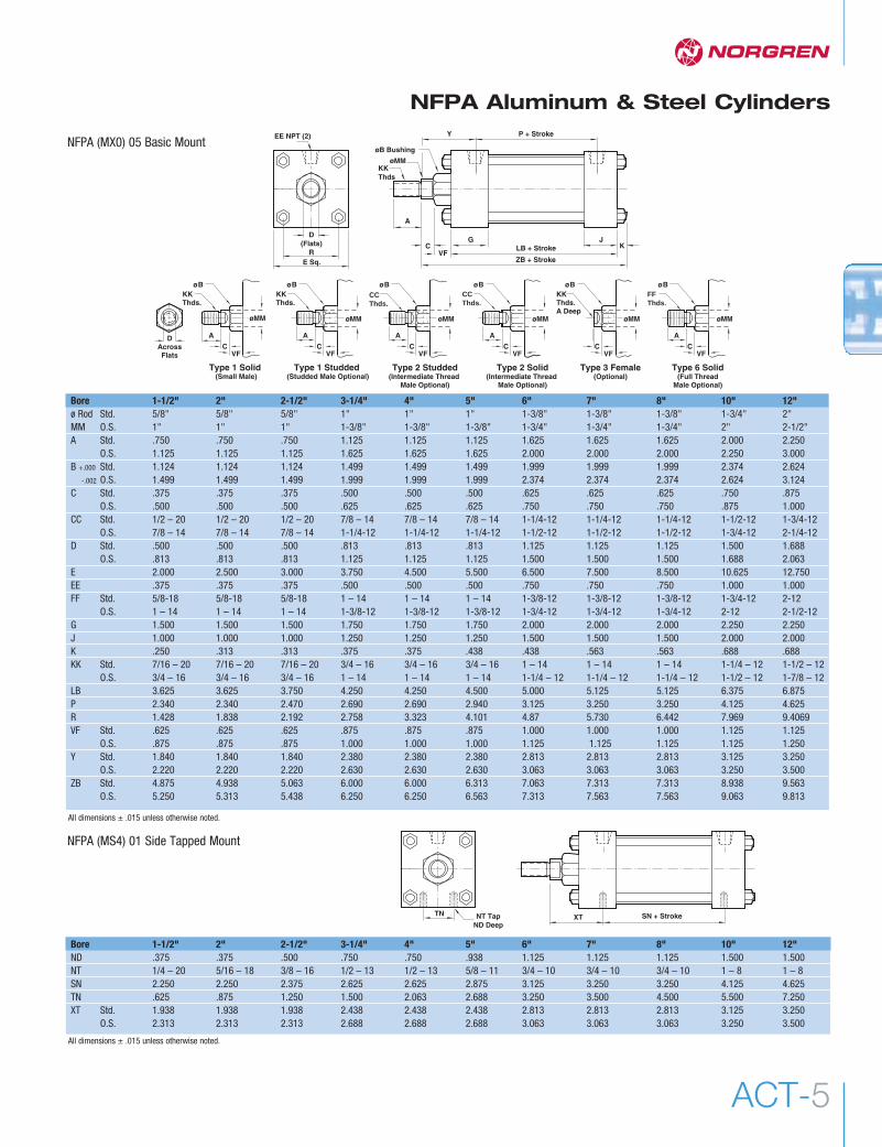
Bore 1-1/2" 2" 2-1/2" 3-1/4" 4" 5" 6" 7" 8" 10" 12"ND .375 .375 .500 .750 .750 .938 1.125 1.125 1.125 1.500 1.500NT 1/4 – 20 5/16 – 18 3/8 – 16 1/2 – 13 1/2 – 13 5/8 – 11 3/4 – 10 3/4 – 10 3/4 – 10 1 – 8 1 – 8SN 2.250 2.250 2.375 2.625 2.625 2.875 3.125 3.250 3.250 4.125 4.625TN .625 .875 1.250 1.500 2.063 2.688 3.250 3.500 4.500 5.500 7.250XT Std. 1.938 1.938 1.938 2.438 2.438 2.438 2.813 2.813 2.813 3.125 3.250
O.S. 2.313 2.313 2.313 2.688 2.688 2.688 3.063 3.063 3.063 3.250 3.500
A
CVF
G
ZB + Stroke
LB + StrokeJ
K
P + StrokeY
øB Bushing
øMMKKThds
D(Flats)
EE NPT (2)
RE Sq.
A
ø B
øMM
A
øMM
ø BKK Thds.
KKThds.A Deep
ø B
øMM
A
ø B
øMM
ø B
øMM
Type 2 Studded(Intermediate Thread
Male Optional)
Type 3 Female(Optional)
Type 2 Solid(Intermediate Thread
Male Optional)
Type 6 Solid(Full Thread
Male Optional)
DAcrossFlats
A
øMM
ø BKK Thds.
Type 1 Studded (Studded Male Optional)
Type 1 Solid (Small Male)
CVF
CVF
CVF
CVF
CVF
A
CVF
CCThds.
CCThds.
FFThds.
Bore 1-1/2" 2" 2-1/2" 3-1/4" 4" 5" 6" 7" 8" 10" 12"ø Rod Std. 5/8" 5/8" 5/8" 1" 1" 1" 1-3/8" 1-3/8" 1-3/8" 1-3/4" 2"MM O.S. 1" 1" 1" 1-3/8" 1-3/8" 1-3/8" 1-3/4" 1-3/4" 1-3/4" 2" 2-1/2"A Std. .750 .750 .750 1.125 1.125 1.125 1.625 1.625 1.625 2.000 2.250
O.S. 1.125 1.125 1.125 1.625 1.625 1.625 2.000 2.000 2.000 2.250 3.000B +.000 Std. 1.124 1.124 1.124 1.499 1.499 1.499 1.999 1.999 1.999 2.374 2.624
-.002 O.S. 1.499 1.499 1.499 1.999 1.999 1.999 2.374 2.374 2.374 2.624 3.124C Std. .375 .375 .375 .500 .500 .500 .625 .625 .625 .750 .875
O.S. .500 .500 .500 .625 .625 .625 .750 .750 .750 .875 1.000CC Std. 1/2 – 20 1/2 – 20 1/2 – 20 7/8 – 14 7/8 – 14 7/8 – 14 1-1/4-12 1-1/4-12 1-1/4-12 1-1/2-12 1-3/4-12
O.S. 7/8 – 14 7/8 – 14 7/8 – 14 1-1/4-12 1-1/4-12 1-1/4-12 1-1/2-12 1-1/2-12 1-1/2-12 1-3/4-12 2-1/4-12D Std. .500 .500 .500 .813 .813 .813 1.125 1.125 1.125 1.500 1.688
O.S. .813 .813 .813 1.125 1.125 1.125 1.500 1.500 1.500 1.688 2.063E 2.000 2.500 3.000 3.750 4.500 5.500 6.500 7.500 8.500 10.625 12.750EE .375 .375 .375 .500 .500 .500 .750 .750 .750 1.000 1.000FF Std. 5/8-18 5/8-18 5/8-18 1 – 14 1 – 14 1 – 14 1-3/8-12 1-3/8-12 1-3/8-12 1-3/4-12 2-12
O.S. 1 – 14 1 – 14 1 – 14 1-3/8-12 1-3/8-12 1-3/8-12 1-3/4-12 1-3/4-12 1-3/4-12 2-12 2-1/2-12G 1.500 1.500 1.500 1.750 1.750 1.750 2.000 2.000 2.000 2.250 2.250J 1.000 1.000 1.000 1.250 1.250 1.250 1.500 1.500 1.500 2.000 2.000K .250 .313 .313 .375 .375 .438 .438 .563 .563 .688 .688KK Std. 7/16 – 20 7/16 – 20 7/16 – 20 3/4 – 16 3/4 – 16 3/4 – 16 1 – 14 1 – 14 1 – 14 1-1/4 – 12 1-1/2 – 12
O.S. 3/4 – 16 3/4 – 16 3/4 – 16 1 – 14 1 – 14 1 – 14 1-1/4 – 12 1-1/4 – 12 1-1/4 – 12 1-1/2 – 12 1-7/8 – 12LB 3.625 3.625 3.750 4.250 4.250 4.500 5.000 5.125 5.125 6.375 6.875P 2.340 2.340 2.470 2.690 2.690 2.940 3.125 3.250 3.250 4.125 4.625R 1.428 1.838 2.192 2.758 3.323 4.101 4.87 5.730 6.442 7.969 9.4069VF Std. .625 .625 .625 .875 .875 .875 1.000 1.000 1.000 1.125 1.125
O.S. .875 .875 .875 1.000 1.000 1.000 1.125 1.125 1.125 1.125 1.250Y Std. 1.840 1.840 1.840 2.380 2.380 2.380 2.813 2.813 2.813 3.125 3.250
O.S. 2.220 2.220 2.220 2.630 2.630 2.630 3.063 3.063 3.063 3.250 3.500ZB Std. 4.875 4.938 5.063 6.000 6.000 6.313 7.063 7.313 7.313 8.938 9.563
O.S. 5.250 5.313 5.438 6.250 6.250 6.563 7.313 7.563 7.563 9.063 9.813
NT TapND Deep
TN SN + StrokeXT
NFPA (MX0) 05 Basic Mount
NFPA (MS4) 01 Side Tapped Mount
All dimensions ± .015 unless otherwise noted.
All dimensions ± .015 unless otherwise noted.
Actuators
www.norgren.com/usaACT-6
NFPA Aluminum & Steel Cylinders
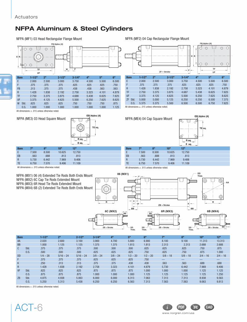
Bore 1-1/2" 2" 2-1/2" 3-1/4" 4" 5" 6"E 2.000 2.500 3.000 3.750 4.500 5.500 6.500F .375 .375 .375 .625 .625 .625 .750FB .313 .375 .375 .438 .438 .563 .563R 1.428 1.838 2.192 2.758 3.323 4.101 4.879TF 2.750 3.375 3.875 4.688 5.438 6.625 7.625UF 3.375 4.125 4.625 5.500 6.250 7.625 8.625W Std. .625 .625 .625 .750 .750 .750 .875
O.S. 1.000 1.000 1.000 1.000 1.000 1.000 1.125
RE
TF
UF
FW
FB Holes (4)
Bore 7" 8" 10" 12"E 7.500 8.500 10.625 12.750EB .563 .688 .813 .813R 5.730 6.442 7.969 9.406TE 6.750 7.570 9.406 11.109
Bore 7" 8" 10" 12"E 7.500 8.500 10.625 12.750EB .563 .688 .813 .813R 5.730 6.442 7.969 9.406TE 6.750 7.570 9.406 11.109
E sq.
R sq.
EB Holes (4)
TE sq.
E sq.
R sq.
EB Holes (4)
TE sq.
Bore 1-1/2" 2" 2-1/2" 3-1/4" 4" 5" 6" 7" 8" 10" 12"AA 2.020 2.600 3.100 3.900 4.700 5.800 6.900 8.100 9.100 11.313 13.313BB 1.000 1.125 1.125 1.375 1.375 1.813 1.813 2.313 2.313 2.688 2.688C Std. .375 .375 .375 .500 .500 .500 .625 .625 .625 .750 .875
O.S. .500 .500 .500 .625 .625 .625 .750 .625 .750 .875 1.000DD 1/4 – 28 5/16 – 24 5/16 – 24 3/8 – 24 3/8 – 24 1/2 – 20 1/2 – 20 5/8 – 18 5/8 – 18 3/4 – 16 3/4 – 16F .375 .375 .375 .625 .625 .625 .750 — — — —K .250 .313 .313 .375 .375 .438 .438 .563 .563 .688 .688R 1.428 1.838 2.192 2.758 3.323 4.101 4.879 5.730 6.442 7.969 9.406VF Std. .625 .625 .625 .875 .875 .875 1.000 1.000 1.000 1.125 1.125
O.S. .875 .875 .875 1.000 1.000 1.000 1.125 1.125 1.125 1.125 1.250ZB Std. 4.875 4.938 5.063 6.000 6.000 6.313 7.063 7.313 7.313 8.938 9.563
O.S. 5.250 5.313 5.438 6.250 6.250 6.563 7.313 7.563 7.563 9.063 9.813
NFPA (MF1) 03 Head Rectangular Flange Mount
Bore 1-1/2" 2" 2-1/2" 3-1/4" 4" 5" 6"E 2.000 2.500 3.000 3.750 4.500 5.500 6.500F .375 .375 .375 .625 .625 .625 .750R 1.428 1.838 2.192 2.758 3.323 4.101 4.879TF 2.750 3.375 3.875 4.687 5.438 6.625 7.625UF 3.375 4.125 4.625 5.500 6.250 7.625 8.625ZF Std. 5.000 5.000 5.125 6.250 6.250 6.500 7.375
O.S. 5.375 5.375 5.500 6.500 6.500 6.750 7.625
F
RE
TF
FB Holes (4)
ZF + Stroke UF
NFPA (MF2) 04 Cap Rectangular Flange Mount
NFPA (ME3) 03 Head Square Mount NFPA (ME4) 04 Cap Square Mount
R C
ZB + Stroke
F
R
DDThds
6C (MX2) 6B (MX4)
ZB + Stroke
BB
DDThds.
6R (MX3)
ZB + Stroke
BB
ZB + Stroke BB
VF K
AA
BB BB
DDThds.
DDThds.
06 (MX1)NFPA (MX1) 06 (4) Extended Tie Rods Both Ends MountNFPA (MX2) 6C Cap Tie Rods Extended MountNFPA (MX3) 6R Head Tie Rods Extended MountNFPA (MX4) 6B (2) Extended Tie Rods Both Ends Mount
All dimensions ± .015 unless otherwise noted.
All dimensions ± .015 unless otherwise noted.
All dimensions ± .015 unless otherwise noted. All dimensions ± .015 unless otherwise noted.
All dimensions ± .015 unless otherwise noted.

ACT-7
NFPA Aluminum & Steel Cylinders
UTXG
øTD
TL TL
Bore 1-1/2" 2" 2-1/2" 3-1/4" 4" 5" 6" 7" 8" 10" 12"TD +.000 -.001 1.000 1.000 1.000 1.000 1.000 1.000 1.375 1.375 1.375 1.750 1.750TL 1.000 1.000 1.000 1.000 1.000 1.000 1.375 1.375 1.375 1.750 1.750UT 4.000 4.500 5.000 5.750 6.500 7.500 9.250 10.250 11.250 14.125 16.250XG Std. 1.750 1.750 1.750 2.250 2.250 2.250 2.625 2.625 2.625 3.000 3.125
O.S. 2.125 2.125 2.125 2.500 2.500 2.500 2.875 2.875 2.875 3.125 3.375
NFPA (MT1) 07 Head Trunnion Mount
øTD
UTTL
XJ + Stroke
TL
Bore 1-1/2" 2" 2-1/2" 3-1/4" 4" 5" 6" 7" 8" 10" 12"TD +.000 -.001 1.000 1.000 1.000 1.000 1.000 1.000 1.375 1.375 1.375 1.750 1.750TL 1.000 1.000 1.000 1.000 1.000 1.000 1.375 1.375 1.375 1.750 1.750UT 4.000 4.500 5.000 5.750 6.500 7.500 9.250 10.250 11.250 14.125 16.250XJ Std. 4.125 4.125 4.250 5.000 5.000 5.250 5.875 6.000 6.000 7.250 7.875
O.S. 4.500 4.500 4.625 5.250 5.250 5.500 6.125 6.250 6.250 7.375 8.125
NFPA (MT2) 8R & 08 Cap Trunnion Mount
XS
G J
TSUS SS + Stroke
SU SJ
ST
øSB
SW
SH
SW
Bore 1-1/2" 2" 2-1/2" 3-1/4" 4" 5" 6" 7" 8" 10" 12"G 1.500 1.500 1.500 1.750 1.750 1.750 2.000 2.000 2.000 2.250 2.250J 1.000 1.000 1.000 1.250 1.250 1.250 1.500 1.500 1.500 2.000 2.000SB .438 .438 .438 .563 .563 .813 .813 .813 .813 1.063 1.063SH 1.000 1.250 1.500 1.875 2.250 2.750 3.250 3.750 4.250 5.313 6.375SJ .625 .625 .625 .750 .750 .813 .813 .813 .813 2.000 2.000SS 2.875 2.875 3.000 3.250 3.250 3.125 3.625 3.750 3.750 4.625 5.125ST .500 .500 .500 .750 .750 1.000 1.000 1.000 1.000 1.250 1.250SU 1.125 1.125 1.125 1.250 1.250 1.063 1.313 1.563 1.563 2.000 2.000SW .375 .375 .375 .500 .500 .688 .688 .688 .688 .875 .875TS 2.750 3.250 3.750 4.750 5.500 6.875 7.875 8.875 9.875 12.375 14.500US 3.500 4.000 4.500 5.750 6.500 8.250 9.250 10.250 11.250 14.125 16.250XS Std. 1.375 1.375 1.375 1.875 1.875 2.062 2.313 2.313 2.313 2.750 2.875
O.S. 1.750 1.750 1.750 2.125 2.125 2.313 2.562 2.563 2.563 2.875 3.125
NFPA (MS2) 09 Side Lug Mount
All dimensions ± .015 unless otherwise noted.
All dimensions ± .015 unless otherwise noted.
All dimensions ± .015 unless otherwise noted.

Actuators
www.norgren.com/usaACT-8
NFPA Aluminum & Steel Cylinders
UM XI (Min.)
øTD
TL
UV
TM BDTLCustomer
Must SpecifyXI
Bore 1-1/2" 2" 2-1/2" 3-1/4" 4" 5" 6" 7" 8" 10" 12"BD 1.250 1.500 1.500 2.000 2.000 2.000 2.500 2.500 2.500 3.000 3.000TD +.000 -.001 1.000 1.000 1.000 1.000 1.000 1.000 1.375 1.375 1.375 1.750 1.750TL 1.000 1.000 1.000 1.000 1.000 1.000 1.375 1.375 1.375 1.750 1.750TM 2.500 3.000 3.500 4.500 5.250 6.250 7.625 8.750 9.750 12.000 14.000UM 4.500 5.000 5.500 6.500 7.250 8.250 10.375 11.500 12.500 15.500 17.500UV 2.500 3.000 3.500 4.250 5.000 6.000 7.000 8.500 9.500 11.750 13.750XI min. Std. 3.125 3.250 3.250 4.125 4.125 4.125 4.625 4.875 4.875 5.625 5.750
O.S. 3.500 3.625 3.625 4.375 4.375 4.375 4.875 5.125 5.125 5.750 6.000
NFPA (MT4) 10 Center Trunnion Mount
SA + Stroke
LB + Stroke
AT
S øAB
AH
AOALNF
WF
Bore 1-1/2" 2" 2-1/2" 3-1/4" 4" 5" 6" 7" 8" 10" 12"AB .438 .438 .438 .563 .563 .688 .813 .813 .813 1.063 1.063AH 1.188 1.438 1.625 1.938 2.250 2.750 3.250 3.750 4.250 5.313 6.375AL 1.000 1.000 1.000 1.250 1.250 1.375 1.375 1.813 1.813 2.125 2.125AO .375 .375 .375 .500 .500 .625 .625 .688 .688 .875 .875AT .125 .125 .125 .125 .125 .187 .187 .250 .250 .250 .250LB 3.625 3.625 3.750 4.250 4.250 4.500 5.000 5.125 5.125 6.375 6.875NF 1.375 1.375 1.375 1.875 1.875 2.000 2.125 1.813 1.813 1.813 1.813S 1.250 1.750 2.250 2.750 3.500 4.250 5.250 6.125 7.125 8.875 11.000SA 6.000 6.000 6.125 7.375 7.375 7.875 8.500 8.750 8.750 10.625 11.125WF STD. 1.000 1.000 1.000 1.375 1.375 1.375 1.625 1.625 1.625 1.875 2.000
O.S. 1.375 1.375 1.375 1.625 1.625 1.625 1.875 1.875 1.875 2.000 2.250
NFPA (MS1) 11 Side End Angle Mount
XC + Stroke
LB + Stroke L
LR
øCD
MR
CBCW CW
Standard pinincluded
Bore 1-1/2" 2" 2-1/2" 3-1/4" 4" 5" 6" 7" 8" 10" 12"CB .750 .750 .750 1.250 1.250 1.250 1.500 1.500 1.500 2.000 2.500CD .500 .500 .500 .750 .750 .750 1.000 1.000 1.000 1.375 1.750CW .500 .500 .500 .625 .625 .625 .750 .750 .750 1.000 1.250L .750 .750 .750 1.250 1.250 1.250 1.500 1.500 1.500 2.125 2.250LB 3.625 3.625 3.750 4.250 4.250 4.500 5.000 5.125 5.125 6.375 6.875LR .750 .750 .750 1.250 1.250 1.250 1.500 1.500 1.500 1.875 2.125MR .625 .625 .625 .938 .938 .938 1.188 1.188 1.188 1.625 2.125XC Std. 5.375 5.375 5.500 6.875 6.875 7.125 8.125 8.250 8.250 10.375 11.125
O.S. 5.750 5.750 5.875 7.125 7.125 7.375 8.375 8.500 8.500 10.500 11.375
NFPA (MP1) 12 Cap Fixed Clevis Mount
All dimensions ± .015 unless otherwise noted.
All dimensions ± .015 unless otherwise noted.
All dimensions ± .015 unless otherwise noted.

ACT-9
NFPA Aluminum & Steel Cylinders
Bore 1-1/2" 2" 2-1/2" 3-1/4" 4" 5" 6" 7" 8"EB .313 .375 .375 .438 .438 .563 .563 .688 .688EF 1.125 1.313 1.438 1.500 1.625 1.688 1.750 1.750 1.750EL .750 .938 1.063 .875 1.000 1.063 1.000 1.125 1.125EO .250 .313 .313 .375 .375 .500 .500 .625 .625ET .500 .750 .750 1.000 1.250 1.500 1.500 1.750 2.063R 1.428 1.838 2.192 2.758 3.323 4.101 4.879 5.730 6.442SE 5.500 5.875 6.250 6.625 6.875 7.250 7.750 7.375 7.375ZE Std. 5.625 5.875 6.125 6.875 7.000 7.438 8.125 8.500 8.500
O.S. 6.000 6.250 6.500 7.125 7.250 7.688 8.375 8.750 8.750
EOZE + Stroke
øEB Hole (4)
ET
EL
SE + Stroke
R EFEO
NFPA (MS7) 15 End Lug Mount
Bore 1-1/2" 2" 2-1/2" 3-1/4" 4" 5" 6"DD 1/4-28 5/16-24 5/16-24 3/8-24 3/8-24 1/2-20 1/2-20NT 1/4 – 20 5/16 – 18 3/8 – 16 1/2 – 13 1/2 – 13 5/8 – 11 3/4 – 10ND .375 .375 .500 .750 .750 .938 1.125SN 2.250 2.250 2.375 2.625 2.625 2.875 3.125TN .625 .875 1.250 1.500 2.063 2.688 3.250XT Std. 1.938 1.938 1.938 2.438 2.438 2.438 2.813
O.S. 2.313 2.313 2.313 2.688 2.688 2.688 3.063
NT Tap ND Depth
XT SN + StrokeTN
øDD 4 plcs (both ends)
16 Sleeve Nut Construction Side Tapped (Universal Mount)
Bore 1-1/2" 2" 2-1/2" 3-1/4" 4" 5" 6"F .375 .375 .375 .625 .625 .625 .750FB .313 .375 .375 .438 .438 .563 .563G 1.500 1.500 1.500 1.750 1.750 1.750 2.000R 1.428 1.838 2.192 2.758 3.323 4.101 4.879TF 2.750 3.375 3.875 4.688 5.438 6.625 7.625UF 3.375 4.125 4.625 5.500 6.250 7.625 8.625V Std. .250 .250 .250 .250 .250 .250 .250
O.S. .500 .500 .500 .375 .375 .375 .375W Std. .625 .625 .625 .750 .750 .750 .875
O.S. 1.000 1.000 1.000 1.000 1.000 1.000 1.125WF Std. 1.000 1.000 1.000 1.375 1.375 1.375 1.625
O.S. 1.375 1.375 1.375 1.625 1.625 1.625 1.875
VG
FW
WF
UFTF
RFB Holes (8)
NFPA (MF5) 20 Head Square Flange Mount
Bore 1-1/2" 2" 2-1/2" 3-1/4" 4" 5" 6"F .375 .375 .375 .625 .625 .625 .750FB .313 .375 .375 .438 .438 .563 .563J 1.000 1.000 1.000 1.250 1.250 1.250 1.500LB 3.625 3.625 3.750 4.250 4.250 4.500 5.000R 1.428 1.838 2.192 2.758 3.323 4.101 4.879TF 2.750 3.375 3.875 4.688 5.438 6.625 7.625UF 3.375 4.125 4.625 5.500 6.250 7.625 8.625XF Std. 4.625 4.625 4.750 5.625 5.625 5.875 6.625
O.S. 5.000 5.000 5.125 5.875 5.875 6.125 6.875ZF Std. 5.000 5.000 5.125 6.250 6.250 6.500 7.375
O.S. 5.375 5.375 5.500 6.500 6.500 6.750 7.625
UF TF
FB Holes (8)ZF + Stroke
LB + StrokeJ
F
RXF + Stroke
NFPA (MF6) 21 Cap Square Flange Mount
Bore 1-1/2" 2" 2-1/2" 3-1/4" 4" 5" 6" 7" 8"CB .750 .750 .750 1.250 1.250 1.250 1.500 1.500 1.500CD .500 .500 .500 .750 .750 .750 1.000 1.000 1.000CW .500 .500 .500 .625 .625 .625 .750 .750 .750FL 1.125 1.125 1.125 1.875 1.875 1.875 2.250 2.250 2.250L .750 .750 .750 1.250 1.250 1.250 1.500 1.500 1.500LR .750 .750 .750 1.250 1.250 1.250 1.500 1.500 1.500M .500 .500 .500 .750 .750 .750 1.000 1.000 1.000MR .625 .625 .625 .938 .938 .938 1.188 1.188 1.188XD Std. 5.750 5.750 5.875 7.500 7.500 7.750 8.875 9.000 9.000
O.S. 6.125 6.125 6.250 7.750 7.750 8.000 9.125 9.250 9.250
XD + Stroke
L
MFL
øCD
MR
LR
CBCW CW
NFPA (MP2) 22 Detachable Cap Clevis Mount
Bore 1-1/2" 2" 2-1/2" 3-1/4" 4" 5" 6" 7" 8"CB .750 .750 .750 1.250 1.250 1.250 1.500 1.500 1.500CD .500 .500 .500 .750 .750 .750 1.000 1.000 1.000FL 1.125 1.125 1.125 1.875 1.875 1.875 2.250 2.250 2.250L .750 .750 .750 1.250 1.250 1.250 1.500 1.500 1.500LR .750 .750 .750 1.250 1.250 1.250 1.500 1.500 1.500M .500 .500 .500 .750 .750 .750 1.000 1.000 1.000MR .625 .625 .625 .938 .938 .938 1.188 1.188 1.188XD Std. 5.750 5.750 5.875 7.500 7.500 7.750 8.875 9.000 9.000
O.S. 6.125 6.125 6.250 7.750 7.750 8.000 9.125 9.250 9.250
FL CBXD + Stroke
L
M
øCD
MR
LR
NFPA (MP4) 42 Detachable Cap Eye Mount
All dimensions ± .015 unless otherwise noted.

Actuators
www.norgren.com/usaACT-10
NFPA Aluminum & Steel Cylinders
Bore 1-1/2" 2" 2-1/2" 3-1/4" 4" 5" 6" 7" 8"AM .750 .750 .750 1.000 1.000 1.000 1.250 1.250 1.250BI .438 .438 .438 .656 .656 .656 .875 .875 .875DC .500 .500 .500 .750 .750 .750 1.000 1.000 1.000FT .625 .625 .625 1.000 1.000 1.000 1.250 1.250 1.250KL .969 .969 .969 1.406 1.406 1.406 1.719 1.719 1.719XC Std. 5.375 5.375 5.500 6.875 6.875 7.125 8.125 8.250 8.250
O.S. 5.750 5.750 5.875 7.125 7.125 7.375 8.375 8.500 8.500
AM
øDC
XC + Stroke
FT
KL
BI
52 (Not NFPA) Spherical Bearing Mount
Bore 1-1/2" 2" 2-1/2" 3-1/4" 4" 5" 6"G 1.500 1.500 1.500 1.750 1.750 1.750 2.000SH 1.250 1.500 1.875 2.375 2.750 3.500 4.000 SS 2.875 2.875 3.000 3.250 3.250 3.125 3.625ST .250 .250 .375 .500 .500 .750 .750SU 1.125 1.125 1.125 1.250 1.250 1.063 1.313SW .375 .375 .375 .500 .500 .688 .688TS 2.750 3.250 3.750 4.750 5.500 6.875 7.875US 3.500 4.000 4.500 5.750 6.500 8.250 9.250XS Std. 1.375 1.375 1.375 1.875 1.875 2.063 2.313
O.S. 1.750 1.750 1.750 2.125 2.125 2.313 2.563
XS
GTSUS SS + Stroke
SU
ST
SW
SH
60 Base (Not NFPA) Bar Mount
XC + StrokeL M
CB
øCD
MR
LR
Bore 1-1/2" 2" 2-1/2" 3-1/4" 4" 5" 6" 7" 8" 10" 12"CB .750 .750 .750 1.250 1.250 1.250 1.500 1.500 1.500 2.000 2.500CD .500 .500 .500 .750 .750 .750 1.000 1.000 1.000 1.375 1.750L .750 .750 .750 1.250 1.250 1.250 1.500 1.500 1.500 2.125 2.250LR .750 .750 .750 1.250 1.250 1.250 1.500 1.500 1.500 1.875 2.125M .500 .500 .500 .750 .750 .750 1.000 1.000 1.000 1.375 1.750MR .625 .625 .625 .938 .938 .938 1.188 1.188 1.188 1.625 2.125XC Std. 5.375 5.375 5.500 6.875 6.875 7.125 8.125 8.250 8.250 10.375 11.125
O.S. 5.750 5.750 5.875 7.125 7.125 7.375 8.375 8.500 8.500 10.500 11.375
NFPA (MP3) 32 Cap Fixed Eye
ZL + Stroke
WF
ZM + 2x Stroke
LD + Stroke
Bore 1-1/2" 2" 2-1/2" 3-1/4" 4" 5" 6" 7" 8" 10" 12"LD 4.125 4.125 4.250 4.750 4.750 5.000 5.500 5.625 5.625 6.625 7.125WF Std. 1.000 1.000 1.000 1.375 1.375 1.375 1.625 1.625 1.625 1.875 2.000
O.S. 1.375 1.375 1.375 1.625 1.625 1.625 1.875 1.875 1.875 2.000 2.250ZL Std. 5.375 5.438 5.563 6.500 6.500 6.813 7.563 7.813 7.813 10.375 11.125
O.S. 5.750 5.813 5.938 6.750 6.750 7.063 7.813 8.125 8.125 10.625 11.625ZM Std. 6.125 6.125 6.250 7.500 7.500 7.750 8.750 8.875 8.875 9.250 9.675
O.S. 6.875 6.875 7.000 8.000 8.000 8.200 9.250 9.375 9.375 9.375 10.375
NFPA (MX0) 05 Basic with Double Rod End Cylinder
All dimensions ± .015 unless otherwise noted.
All dimensions ± .015 unless otherwise noted.
All dimensions ± .015 unless otherwise noted.
All dimensions ± .015 unless otherwise noted.

ACT-11
NFPA Aluminum & Steel CylindersER Radius
LCE
KK Thds. CH Across Hex Flats
CBCW CW
øCD
A
ER RadiusCD
KK Thds.
øCD
CBCD
CD
CE
A
WøD
K
H
ZerkFitting
øB
C
KK Thds. J
˚ a Clevis Mounted
N
L
CE
KK Thds.
CW CW
øCD
CB
CH
AFH
KK Thds.
52025 52026 52027 52010 52029 52030 52085KK 7/16 – 20 1/2 – 20 5/8 – 18 3/4 – 16 7/8 – 14 1 – 14 1-1/4 – 12AF .688 .750 .938 1.125 1.313 1.500 1.875H .250 .313 .375 .422 .484 .547 .719
52092 52068 52082 52070 52093 52083 52075KK 1-3/8 – 12 1-1/2 – 12 1-3/4 – 12 1-7/8 – 12 2 – 12 2-1/4 – 12 2-1/2 – 12AF 2.063 2.250 2.625 2.938 3.125 3.500 3.875H .781 .844 .969 1.031 1.094 1.203 1.453
Spherical Rod Eye 49220 49221 49222Spherical Rod Eye Assy. 49220A 49221A 49222ABore 1-1/2, 2 & 2-1/2 3-1/4, 4 & 5 6 & 8
KK UNF-2B 1/2 – 20 3/4 – 16 1 – 14a° Misalignment Angle 12 14 14A ± .015 2.125 2.875 4.125B + .0025 / -.0005 .500 .750 1.000C + .062/ -.031 1.063 1.563 2.125D ± .010 1.313 1.750 2.750H Reference .453 .593 1.000J ± .010 .750 1.000 1.500K ± .010 .875 1.125 1.625W + .000 / -.005 .625 .875 1.375
NFPA Rod Clevis
NFPA Rod Eye
Spherical Rod Eye
Small Rod Clevis & Jam Nut
Rod Jam Nut
Rod Clevis Rod Clevis Assy. KK CB CD CE CH CW L N49218 49218A 1/2 – 20 .500 .500 1.375 1.000 .250 .750 .37549219 49219A 3/4 – 16 .750 .750 1.750 1.500 .375 1.000 .500
Note: Rod Clevis Assembly is suppliedwith Jam Nut and Standard Pin.
Note: Rod Eye Assembly 49062A and49096A are supplied with NFPA Pin. Allothers are supplied with Standard Pin
Note: Rod Clevis Assembly 49102A and49103A are supplied with NFPA Pin. Allothers are with Standard Pin
Rod Eye Rod Eye Assy. KK A CB CD CE ER49015 49015A 7/16 – 20 .750 .750 .500 1.500 .56349014 49014A 1/2 – 20 .750 .750 .500 1.500 .56349091 49091A 5/8 – 18 .750 1.250 .750 2.063 .50049013 49013A 3/4 – 16 1.125 1.250 .750 2.063 .93849092 49092A 7/8 – 14 1.125 1.250 .750 2.063 .75049011 49011A 1 – 14 1.625 1.500 1.000 2.813 1.12549010 49010A 1-1/4 – 12 2.000 2.000 1.375 3.438 1.56349093 49093A 1-3/8 – 12 1.625 2.000 1.375 3.438 1.37549009 49009A 1-1/2 – 12 2.250 2.500 1.750 4.000 2.50049094 49094A 1-3/4 – 12 2.250 2.500 1.750 4.000 2.50049007 49007A 1-7/8 – 12 3.000 2.500 2.000 5.000 2.87549095 49095A 2 – 12 2.250 2.500 2.000 5.000 2.87549062 49062A 2-1/4 – 12 3.000 3.000 2.500 5.813 3.25049096 49096A 2-1/2 – 12 3.000 3.000 3.000 6.125 3.250
Rod Clevis Rod Clevis Assy. KK CB CD CE CH CW ER L49028 49028A 7/16 – 20 .750 .500 1.500 1.000 .500 .500 .75049029 49029A 1/2 – 20 .750 .500 1.500 1.000 .500 .500 .75049097 49097A 5/8 – 18 .750 .500 1.500 1.000 .500 .500 .75049030 49030A 3/4 – 16 1.250 .750 2.375 1.250 .625 .750 1.25049098 49098A 7/8 – 14 1.250 .750 2.375 1.250 .625 .750 1.25049032 49032A 1 – 14 1.500 1.000 3.125 1.500 .750 1.000 1.50049033 49033A 1-1/4 – 12 2.000 1.375 4.125 2.000 1.000 1.375 2.12549099 49099A 1-3/8 – 12 2.000 1.375 4.125 2.000 1.000 1.000 2.12549034 49034A 1-1/2 – 12 2.500 1.750 4.500 2.375 1.250 1.750 2.25049100 49100A 1-3/4 – 12 2.500 1.750 4.500 2.375 1.250 1.750 2.25049036 49036A 1-7/8 – 12 2.500 2.000 5.500 2.937 1.250 2.000 2.50049101 49101A 2 – 12 2.500 2.000 5.500 2.937 1.250 2.000 2.50049102 49102A 2-1/4 – 12 3.000 2.500 6.500 3.500 1.500 2.750 3.00049103 49103A 2-1/2 – 12 3.000 3.000 6.750 3.875 1.500 2.750 3.250
FFL
E
CB
øDD4 Places
BA
BAE
LR Radius
øCD
M Radius
FFL
E
CB
øDD4 Places
BA
BA
E
LR Radius
øCD
M Radius
NFPA Eye Bracket
NFPA Eye Bracket 49021 49020 49019 49016 49017 49018Eye Bracket Assembly 49021A 49020A 49019A 49016A 49017A 49018ABA 1.625 2.563 3.250 3.813 4.937 5.750CB .750 1.250 1.500 2.000 2.500 2.500CD .500 .750 1.000 1.375 1.750 2.000DD .406 .531 .656 .656 .906 1.026E 2.500 3.500 4.500 5.000 6.500 7.500F .375 .625 .750 .875 .875 1.000FL 1.125 1.875 2.250 3.000 3.125 3.500LR .750 1.250 1.500 2.125 2.250 2.500M .500 .750 1.000 1.375 1.750 2.000
Norgren Eye Bracket
Eye Bracket 49240 49241 49242 49243 49244 49019 49016 49017 49018Eye BracketAssembly 49240A 49241A 49242A 49243A 49244A 49019A 49016A 49017A 49018ABA 1.438 1.844 2.188 2.938 3.563 3.250 3.813 4.950 5.730CB .750 .750 .750 1.250 1.250 1.500 2.000 2.500 2.500CD .500 .500 .500 .750 .750 1.000 1.375 1.750 2.000DD .281 .344 .344 .469 .469 .656 .656 .906 1.062E 2.000 2.500 3.000 3.750 4.500 4.500 5.000 6.500 7.500F .375 .375 .375 .500 .500 .750 .875 .875 1.000FL 1.125 1.125 1.125 1.750 1.750 2.250 3.000 3.125 3.500LR .563 .563 .563 1.000 1.000 1.500 2.125 2.250 2.500M .625 .625 .625 .875 .875 1.000 1.375 1.750 2.000
Note: NFPA Eye BracketAssembly is supplied withStandard Pin.
Note: Norgren Eye Bracket Assembly issupplied with Standard Pin.
All dimensions ± .015 unless otherwise noted.
NFPA Pin 49006-R 49005-R 49004-R 49003 49002 49001 49000 49126 49127CD. 500 .750 1.000 1.375 1.750 2.000 2.000 2.500 3.000LH 2.219 3.125 3.750 4.750 5.812 5.812 6.312 6.875 6.875LP 1.875 2.750 3.250 4.250 5.250 5.281 5.770 6.312 6.344D – – – .173 .173 .204 .204 .219 .250
øCD
LPLH
øDNFPA Pin
F
E
CB
øDD4 Places
FL
BA
BA
E
CW CW
LR Radius
øCD
M Radius
NFPA Clevis Bracket
øCD
HP
LPLH
Standard Pin
Norgren Clevis Bracket
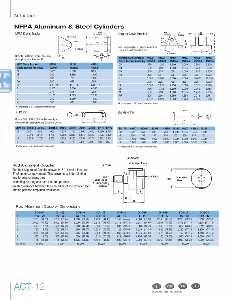
Norgren Clevis Bracket 49022 49023 49024 49027 49025 49026Clevis Bracket Assembly 49022A 49023A 49024A 49027A 49025A 49026ACB .750 1.250 1.500 2.000 2.500 2.500CD .500 .750 1.000 1.375 1.750 2.000CW .500 .625 .750 1.000 1.250 1.500DD .406 .531 .656 .656 .906 1.026E 3.500 5.000 6.500 8.000 10.000 12.000F .500 .625 .750 .875 .875 1.000FL 1.500 1.875 2.250 3.000 3.625 4.520LR .750 1.188 1.500 2.000 2.750 3.188M .500 .750 1.000 1.375 1.750 2.250MR .625 .906 1.250 1.656 2.219 2.781R 2.547 3.828 4.953 5.734 7.500 9.938
MR Radius
FL
øDD4 Places
LRRadius
ER
M
F
CW CWCB
CD .001 Pin Dia. +
NFPA Clevis Bracket 49250 49251 49252Clevis Bracket Assembly 49250A 49251A 49252ABA 1.625 2.563 3.250CB .750 1.250 1.500CD .500 .750 1.000CW .500 .625 .750DD 3/8 – 24 1/2 – 20 5/8 – 18E 2.500 3.500 4.500F .375 .625 .750FL 1.125 1.875 2.250LR .750 1.250 1.500M .500 .813 1.000
Note: NFPA Clevis Bracket Assemblyis supplied with Standard Pin.
Note: Norgren Clevis Bracket Assemblyis supplied with Standard Pin.
Note: ø.500, .750, 1.000 are Retainer typedesign ø1.375 and larger are Cotter Pin design.
Std. Pin 49207* 49208* 49206 49205 49204 49203 49202 49201CD .500 .750 .500 .750 1.000 1.375 1.750 2.000HP .156 .156 .156 .156 .203 .250 .250 .250LH 1.421 2.000 2.250 3.000 3.500 5.000 6.000 6.000LP 1.266 1.843 2.093 2.843 3.297 4.500 5.500 5.500
All dimensions ± .015 unless otherwise noted.
All dimensions ± .015 unless otherwise noted.
All dimensions ± .015 unless otherwise noted. All dimensions ± .015 unless otherwise noted.
ACT-12www.norgren.com/usa
Actuators
NFPA Aluminum & Steel Cylinders
G Across Flats
øF Shank
.062Radial Float2˚ Spherical
Motion
øB
A Thds.
A Thds.
E E
DC
H AcrossFlats
Rod Alignment CouplerThe Rod Alignment Coupler allows 1/16" of radial float and2° of spherical movement. This prevents cylinder bindingdue to misalignment thus extending bearing and seal life, and permits greater tolerance between the centerline of the cylinder andmating part for simplified installation.
B 1.250 1.250 1.250 1.750 1.750 2.500 2.500 3.250 3.250C 2.000 2.000 2.000 2.312 2.312 2.937 2.937 4.375 4.375D .500 .500 .500 .500 .500 .500 .500 .812 .812E .750 .750 .750 1.125 1.125 1.625 1.625 2.250 2.250F .625 .625 .625 .969 .969 1.375 1.375 1.750 1.750G .500 .500 .500 .812 .812 1.156 1.156 1.500 1.500H 1.125 1.125 1.125 1.500 1.500 2.250 2.250 3.000 3.000
Max Pull (lbs.) 10,000 14,000 19,000 34,000 39,000 64,000 78,000 134,000 134,000
Rod Alignment Coupler Dimensions
CC-1-07 CC-1-08 CC-1-10 CC-1-12 CC-1-14 CC-1-16 CC-1-20 CC-1-24 CC-1-28A 7/16 – 20 1/2 – 20 5/8 – 18 3/4 – 16 7/8 – 14 1 – 14 11/4 – 12 11/2 – 12 13/4 – 12
(31.75) (31.75) (31.75) (44.45) (44.45) (63.50) (63.50) (82.50) (82.50)(50.80) (50.80) (50.80) (58.72) (58.72) (74.60) (74.60) (111.13) (111.13)(12.70) (12.70) (12.70) (12.70) (12.70) (12.70) (12.70) (20.62) (20.62)(19.05) (19.05) (19.05) (28.58) (28.58) (41.28) (41.28) (57.15) (57.15)(28.58) (28.58) (28.58) (24.61) (24.61) (34.93) (34.93) (44.45) (44.45)(12.70) (12.70) (12.70) (20.62) (20.62) (29.36) (29.36) (38.10) (38.10)(28.58) (28.58) (28.58) (38.10) (38.10) (57.15) (57.15) (76.20) (76.20)

ACT-13
NFPA Aluminum & Steel Cylinders
PSI Cylinder Bore1-1/2 2 2-1/2 3-1/4 4 5 6 7 8 10 12
0 .14 .15 .17 .19 .22 .25 .28 .32 .32 .36 .4020 .10 .10 .12 .14 .16 .18 .20 .22 .22 .24 .2640 .07 .07 .08 .09 .10 .12 .13 .14 .14 .15 .1660 .04 .04 .05 .05 .06 .07 .07 .08 .08 .09 .1080 .02 .02 .02 .02 .03 .03 .03 .04 .04 .04 .04100 0 0 0 0 0 0 0 0 0 0 0
Cylinder BoreIn/Sec 1-1/2 2 2-1/2 3-1/4 4 5 6 7 8 10 12
6 155.6 275.5 499.8 969.3 1505.4 2603.2 4159.8 5794.2 8067.6 12,242 20,13912 38.4 68.1 123.4 239.7 372.6 644.8 1030.2 1435.8 2000.4 3026 497118 16.7 29.7 53.7 104.6 162.8 282.1 450.6 628.7 876.8 1319.3 2162.124 9.2 16.3 29.4 57.3 89.4 155.2 247.8 346.2 483.6 722 117930 5.6 10.0 18.1 35.4 55.4 96.4 153.9 215.4 301.6 445.5 72436 3.7 6.7 11.9 23.5 37.0 64.5 102.9 144.4 202.7 295.3 476.842 2.6 4.6 8.2 16.3 25.8 45.3 72.2 101.6 143.1 204.8 327.748 1.8 3.2 5.8 11.7 18.6 32.8 52.2 73.8 104.4 146 23154 1.3 2.4 4.2 8.5 13.6 24.2 38.5 54.7 77.9 105.7 164.760 1.0 1.8 3.0 6.2 10.1 18.1 28.7 41.1 58.9 76.9 117.2
Energy Absorption Capacity ofthe Impact Dampening SealsThe impact-dampening Piston Seals in
the Series EJ cylinder allow for guaranteed,repeatable cushioning. The compressivequalities of the piston seals are predictable.The degree of seal compression at varioussupply pressures is documented. (See EnergyAbsorption Chart.) This allows you to computethe exact cylinder size required by knowing theweight (pounds) you are stopping at a givenspeed.
Series EJ cylinders have a impact dampeningpiston seal that accomplishes 80% of theactual load stopping. The air cushion accountsfor only 20%. (A conventional air cushioningcylinder depends 100% on the compressibilityof air to do the stopping.) The EJ seal absorbshigh impact loads allowing the effect of the aircushion to be reduced by using a larger aircushion bleed orifice. As a result the piston canmove at a faster speed for a longer period oftime before the EJ seal does the final stopping. Note: 1-1/2", 2", 2-1/2", 3-1/4", 4" and 5"bore cylinders with 1/2" to 2" strokes will befurnished with a short head cushion sleeve andshort cap cushion spear. Only available on 5/8"and 1" rods. This specification applies toSeries EA cylinders with standard non-adjustable or optional adjustable cushions.
3
Norgren Ecology Cylinders offer these advantages:Norgren Guarantees Non-lubricated Operation for a Full Year!
The piston rod is self-lubricated by the oil-impregnated rod bearing during operation.Lubrication between piston and cylinder barrel isderived from the polishing qualities of thereinforced Teflon® wear ring. The low friction surfaces extend the life of theseals beyond normal expectations, permittingNorgren to unconditionally guarantee non-lubricated operation for one full year. Series EJ cylinders are NFPA interchangeableand are available in many different mountingstyles.
Operates Quietly to Meet OSHA Specifications.
Series EJ cylinders provide substantial reductionsin impact noise, which reduces overall machinenoise and helps meet government regulations.
The summary of sound decibels chart illustratesthe operating sound levels.
The impact dampening qualities of thePiston Seals are guaranteed for ONE FULL YEAR!
1 2
Summary of Sound Levels in Decibels+ Peak sound pressure is given in decibels (dB)
re:2 x 10⁵ N/m2.++End position of mike was 3' on centerline from end of
cylinder; side position of mike was 3' perpendicular tocenterline abeam of end of cylinder.
Note: At 5 feet, cylinder sound levels would be less by 9 dB fromside figure and 13 dB from end figure. The total noise emitted willdepend on the structure to which the cylinder is attached. If it ismounted on a thin flat plate of considerable area, the noise willbe increased by a sounding board effect.
Effect of Impact Dampening Seals on Total Stroke of Cylinders
*The weight of the cylinder piston has been deducted from the figures shown above. Note: The use of Viton® Seals limits the absorption of the impact dampening seals by 50%.
Energy Absorption Capacity of the Impact Dampening Seals*Usable Pounds Stoppable at the Following Piston SpeedsThis chart features the energy absorption capacity of the impact dampening piston seals with a Non-Adjustablecushions. For higher loads and velocities please refer to the Decel- Air Cushion option.
Note: Figures are for new cylinders. Impact dampening seals will take some compression set during operation and the stroke loss willdecrease. Also, the pressure at zero stroke loss will decrease to about 80 psi. At pressures above those of zero stroke loss, a slight clickingsound may be produced during impact. To determine the stroke loss for either the head or cap end, divide the value shown by 2.
PSI Air Sound Cylinder ModelPressure J133B3 EJ155B3 J1133A3 EJ1155A3Level+ 5" x 6" 5" x 6" 2" x 6" 2" x 6"
95 End++ 108 73 110 74PSI+ Side++ 112 84 110 81
50 End++ 108 73 113 74PSI+ Side++ 113 85 110 81
In/Sec Cylinder Bore1-1/2 2 2-1/2 3-1/4 4 5 6 7 8 10 12
6 279 495 899 1,744 2,709 4,685 7,486 10,429 4,520 22,035 36,25012 68 122 221 430 699 1,159 1,854 2,583 3,800 5,446 8,94718 30 53 95 187 291 507 810 1,130 1,576 2,374 3,89124 16 29 52 102 160 279 444 622 869 1,299 1,41430 10 18 32 63 99 172 275 387 541 801 1,30336 6.7 12 21.6 42 66 116 183 259 363 531 85642 4.7 8.3 14.7 29 46 81 129 181 257 367 58848 3.4 5.7 10.4 21 33 59 93 131 187 262 41554 2.3 4.3 7.6 15.3 24 43 68 97 138 189 29560 1.8 3.2 5.4 11 18 33 52 74 106 138 211
Energy absorption capacity of the impact dampening piston seals with anadjustable cushion.
Piston and rod assembly for1-1/2" thru 5" bore cylinderswith 1/2" to 2" stroke

Explanation of Decel-Air Cushion:Norgren’s Decel Cushioned cylinder was designed forapplications where high velocity, low mass, material transferor machine function is required, and where the kinetic energyto be absorbed during cushioning exceeds the parameters ofour standard Series EA or EJ air cylinders equipped with non-adjustable or adjustable cushions. Decel cushions employlonger-than-standard air cushions to assist our ImpactDampening Piston Seal.
In/ Cylinder BoreSec 1-1/2 2 2-1/2 3-1/4 4 5 6 7 8 10 126 558 990 1.798 3.488 5.418 9.370 14.972 20.040 20.858 44.070 72.50012 136 244 442 860 1.338 2.318 3.708 5.166 7.600 10.892 17.89418 60 106 190 374 582 1.014 1.620 2.260 3.152 4.748 7.78224 32 58 104 204 320 558 888 1.244 1.738 2.598 2.82830 20 36 64 126 198 344 550 774 1.082 1.602 2.60636 13.4 24 43 84 132 232 366 518 726 1.062 1.71242 9.4 16.6 29 58 92 162 258 362 514 734 1.17648 6.8 11.4 20.8 42 66 118 186 262 374 524 83054 4.6 8.6 10.8 30 48 86 136 194 276 378 590
Decel Cushioned CylinderFully Cushioned Load Stopping Capacity in Pounds*
*Include piston rod wight in total load to be stopped.
Piston Rod Dia. Weights*5/8" .30 lb. + 0.09 lb./in. stroke1" .90 lb. + 0.22 lb./in. stroke1-3/8" 2.2 lb. + 0.42 lb./in. stroke1-3/4" 4.0 lb. + 0.68 lb./in. stroke2" 5.5 lb. + 0.90 lb./in. stroke2-1/2" 10.1 lb. + 1.40 lb./in. stroke
*Double Weight for double rod end cylinders
G J J J
MB + Stroke
Cyl. + StrokeBore G J MB1-1/2 1-1/2 1 5-5/82 1-1/2 1 5-5/82-1/2 1-1/2 1 5-3/43-1/4 1-3/4 1-1/4 6-3/44 1-3/4 1-1/4 6-3/45 1-3/4 1-1/4 76 2 1-1/2 87 2 1-1/2 8-1/88 2 1-1/2 8-1/8
Basic Envelope Dimensions and weights
Decel-Air™ Cushion
ACT-14www.norgren.com/usa
Actuators
NFPA Aluminum & Steel Cylinders
Air-Oil Tank Volumes (cubic inches)
Air-Oil TankAvailable in 5 practical bore sizes: 1-1/8", 2", 3-1/4", 5", and8", the Air-Oil Tank includes a translucent fiberglass tubewhich permits viewing of the tank oil level from any position,internal baffles that reduce foaming and aeration of thesystem oil resulting in maximum cylinder control, andstandard angle mounting brackets (except 1-1/8" bore) easilyremoved for convenient fluid port positioning.
øJ (4)L NPTFill Port
K NPT Port
*C *B
D
A
K NPTPort
GH
L NPTFill
Port
F E
*D*C*B
EA
1-1/8" Bore only
*plus internal length
Bore 1-1/8" 2" 3-1/4" 5" 8"Area .995 sq." 3.14 sq." 8.30 sq." 19.64 sq." 50.26 sq."6" 5.9 18.6 49.8 117.8 301.58" 7.9 25.1 66.4 157.1 402.010" 9.9 31.4 83.0 196.4 502.612" 11.9 37.6 99.6 235.6 603.114" 13.9 43.9 116.2 274.9 703.616" 15.9 50.2 132.8 314.2 804.118" 17.9 56.5 149.4 353.5 904.520" 19.9 62.8 166.0 392.8 1005.2
Inte
rnal
Len
gth
of T
ank
Air-Oil Tank Dimensions
How to Order: Specify air-oil tank part number and internal length.Example: 2" bore with 6" internal length = AOT-04 x 6
Note: Maximum operating pressure 250 PSI.
1.500 2.687 4.000 5.625 8.6251.250 2.000 2.500 2.500 3.000.750 4.000 5.000 5.250 6.625.750 4.750 6.000 6.500 8.000
.375 .500 .500 .687
.125 .187 .187 .2502.500 3.750 5.500 8.5001.750 2.750 .690 7.125.437 .562 .562 .812
.125 .375 .500 .500 .750
.125 .250 .375 .375 .500
Bore 1-1/8" 2" 3-1/4" 5" 8AOT-225 AOT-04 AOT-065 AOT-10 AOT-16
A (38.10) (68.25) (101.60) (142.88) (219.08)B (31.75) (50.80) (63.50) (63.50) (76.20)C (19.05) (101.60) (127.00) (127.00) (168.28)D (19.05) (120.65) (152.40) (152.40) (203.20)E (9.53) (12.70) (12.70) (17.45)F (3.18) (4.75) (4.75) (6.35)G (63.50) (95.25) (139.70) (215.90)H (44.45) (69.85) (107.95) (180.98)øJ (11.10) (14.27) (14.27) (20.62)K (3.18) (9.53) (12.70) (12.70) (19.05)L (3.18) (6.35) (9.53) (9.53) (12.70)
Volume of Cylinder:• Cap End Cylinder Bore Area x Stroke = Volume• Head End Cylinder Bore Area – (Piston Rod Area) x Stroke = VolumeLength of Tank = Volume of Cylinder x 1.3*
Tank Bore Area(See chart below.) *30% minimum recommended reserve working volume.
Final Length of Volume of Tank = Working length of tank + 2" minimumsafety factor to prevent aeration of oil. Note: Length must be at least 3".
How to Figure Length of VolumeUse these equations to select the right air/oil tank volume for yourparticular application.

ACT-15
NFPA Aluminum & Steel Cylinders
Piston Rod Diameter SelectionApplications requiring long extend (push) strokes may require oversizepiston rod diameters to prevent buckling. To determine the correct rod diameter for your application follow these simple steps:1. Select the force from the Cylinder Force and Volume Chart that is
required for your application. For pressures not shown use:Force = Piston Surface Area x Operating Pressure
2. From the Cylinder Mounting Diagram Chart (next page) select themounting style being used.
3. To obtain effective length “L”, multiply cylinder stroke by appropriatestroke factor located in Cylinder Mounting Diagram Chart . If cylinderhas extra rod extension add this to the stroke length before obtainingeffective length. Effective Length = Actual Stroke x Stroke Factor
4. To determine adequate rod diameter locate calculated effective length“L” on Rod Selection chart (below).
All Dimensions in Inches (mm)All Forces in Pounds (Newtons)
VolumeCu Ft (cm3)
Rod Rod PSI (bar) Displacement Area 40 (3) 60 (4) 80 (6) 100 (7) 150 (10) 200 (14) Per Inch
.307 12 18 25 31 46 61 .00018
.785 31 47 63 78 118 157 .000451.485 59 89 119 149 222 297 .000862.404 96 144 192 240 360 480 .001393.142 126 189 251 314 471 628 .001824.909 196 295 393 491 736 981 .00284
5/8" (1.98) (53) (80) (111) (138) (205) (271) (5)1" (5.06) (138) (209) (280) (351) (525) (698) (13)1-3/8" (9.58) (262) (396) (529) (663) (997) (1321) (24)1-3/4" (15.51) (423) (641) (854) (1068) (1601) (2135) (39)2" (20.16) (559) (839) (1118) (1398) (2096) (2795) (52)2-1/2" (31.67) (873) (1310) (1747) (2184) (3275) (4367) (80)
Deduct these Forces for Retract Strokes
Cylinder Force and Volume ChartsExtend Forces in pounds (newtons)
1-1/2" 1.77 71 106 142 177 266 353 .001022" 3.14 126 189 251 314 471 628 .001822-1/2" 4.91 196 295 393 491 737 982 .002843-1/4" 8.30 332 498 664 830 1245 1659 .004804" 12.57 503 754 1005 1257 1886 2513 .007275" 19.64 785 1178 1571 1964 2946 3928 .011376" 28.27 1130 1696 2262 2827 4240 5654 .016367" 38.49 1540 2309 3079 3849 5774 7698 .022278" 50.26 2010 3015 4020 5026 7539 10052 .0290910" 78.54 3141 4712 6283 7854 11781 15700 .0454512" 113.10 4524 6786 9048 11310 16965 22620 .06545
(11.40) (315) (472) (629) (786) (1179) (1570) (29)(20.27) (559) (839) (1119) (1398) (2097) (2793) (52)(31.67) (874) (1311) (1748) (2185) (3277) (4368) (80)(53.32) (1477) (2215) (2953) (3692) (5538) (7379) (136)(81.07) (2237) (3355) (4473) (5592) (8388) (11178) (206)
(126.71) (3491) (5240) (6988) (8736) (13104) (17472) (322)(182.39) (5026) (7544) (10061) (12574) (18860) (25149) (463)(247.91) (6831) (10242) (13658) (17074) (25613) (34148) (631)(324.26) (8940) (13411) (17881) (22356) (33533) (44711) (829)(506.74) (13974) (20961) (27948) (34935) (52402) (69834) (1282)(729.72) (20123) (30184) (40246) (50307) (75460) (100614) (1852)
VolumeCu Ft (cm3)
Bore Piston PSI (bar) Displacement Area 40 (3) 60 (4) 80 (6) 100 (7) 150 (10) 200 (14) Per Inch
Rod Selection Chart
Note: In some cases it may be necessary to use a larger bore cylinder than is required for force in order to obtain an adequate rod diameter.
Extended Force Maximum effective length “L” recommended for rod diameters(lbs) 5/8" 1" 1-3/8" 1-3/4" 2" 2-1/2"50 95 – – – – –100 65 170 – – – –150 50 135 260 – – –200 43 115 220 – – –300 34 93 180 300 – –500 25 70 135 250 – –750 20 56 110 185 250 –1000 17 48 94 160 220 –1500 13 38 80 130 170 2602000 11 33 64 110 140 2253000 9 26 51 90 115 1804000 7 22 44 75 100 1555000 – 20 39 66 88 1406000 – 18 35 60 79 1258000 – 15 30 52 68 11010000 – 12 26 46 60 9512500 – 10 22 41 52 8615000 – – 19 37 48 7920000 – – 14 29 41 68

Actuators
www.norgren.com/usaACT-16
NFPA Aluminum & Steel Cylinders
Cylinder Rod End Mounting Stroke Mounting Connection Style Factor
Side Tapped, Head or Fixed andCap Flange, Tie Rod, Rigidly Guided .50Center or Side Lug
Side Tapped, Head or Pivoted andCap Flange, Tie Rod, Rigidly Guided .70Center or Side Lug
Side Tapped, Head or Supported butCap Flange, Tie Rod, not Rigidly Guided 2.00Center or Side Lug
Side Tapped, Head orCap Flange, Tie Rod, None 5.00Center or Side Lug
Head Trunnion Pivoted and 1.00Rigidly Guided
Center Trunnion Pivoted and 1.50Rigidly Guided
Cap Trunnion Pivoted andor Clevis Rigidly Guided 2.00
Number of Tie Rod Supports Required
Cylinder Cylinder Stroke (in)Bore 60 75 95 115 135
1-1/2" 1 1 2 2 32" – 1 1 2 2
2-1/2" – – 1 1 13-1/4" – – – 1 1
4" – – – – 15" and over – – – – –
Tie Rod Supports:For long strokes, tie rod supports are provided. These supports are of the same envelope dimensions as the cylinder end caps.NOTE: See chart for number of tie rod supports required.
Cylinder Mounting Diagram Chart

ACT-17
NFPA Aluminum & Steel Cylinders
1. Selecting Stop Tubes: Stop tubes enhance the transverse load carryingcapability of a long stroke cylinder by increasing the distance betweenthe piston and rod bearing at full extension. When the calculated “L”value (effective length = actual stroke x stroke factor) is less than 40"astop tube is not required. However, if “L” is 40" or more, 1" of stop tubeis recommended for every 10" (or fraction thereof) over 40".
2. Recommended Mounting Styles for Maximum Stroke and Thrust Load:Multiply cylinder stroke by appropriate stroke factor to obtain effectivelength “L”.
Bore 1-1/2" (38.10) 2" (50.80) 2-1/2" (63.50) 3-1/4" (82.55) 4" (101.60) 5" (127.00) 6" (152.40) 7" (177.80) 8" (203.20)J 1 (25.40) 1 (25.40) 1 (25.40) 1.250 (31.75) 1.250 (31.75) 1.250 (31.75) 1.500 (38.10) 1.500 (38.10) 1.500 (38.10)
Stop Tube LengthStop Tube Length
Head Stop TubeCap Stop Tube
Stop Tube Length
Head Stop Tube consisting of Spacer Tube and Block
J
NOTE: Care should be taken in machining the keyway slot for a tight fit. Only one keyway should be used per cylinder.
E
E F
FA +.000-.002
PD LN +.000-.005
Norgren’s Standard Thrust Key PlateThrust key plates eliminate the use of fittedbolts or dowel pins on side mountings. They prevent movement of the cylinder under shock loading, which might otherwise occur due to normal clearance between mounting holes and bolt diameters. Option code TK available on01(MS4), 09(MS2) and 15(MS7) mounts.NOTE: Other manufacturers’ thrust keyplates can vary. Consult factory forinformation.
Stop Tube Enhances the transverse load carryingcapability of a long stroke cylinder byincreasing the distance between the pistonand rod bearing at full extension whenplaced on head end. Ideal for thoseapplications requiring longer strokes orwhere additional rod stability is desired.TO ORDER: Enter option code ST(–C) CapEnd or ST(–R) Rod End. Specify stop tubelength.NOTE: ST(–R) Alternate design: the stop tuberod end design changes when the stop tubeexceeds J lengths in the chart.
ST(–C) ST(–R) ST(–R)
Tie Rod Tightening:In order to reduce the possibility of cylinder binding or damage, tighten to quarter unit increments of the final torque value in thefollowing order: #1, #2, #3, #4. Then torque fully to the recommended foot pounds in the same order.
1 3
4 2
Recommended Torques for Tightening Tie RodsCylinder Standard Stainless Steel
Bore Steel Tie Rods Tie Rods1-1/2" 6.6 ft. lbs. 3.75 ft. lbs.
2" 11 ft. lbs. 7.5 ft. lbs.2-1/2" 13 ft. lbs. 7.5 ft. lbs.3-1/4" 20 ft. lbs. 13-14 ft. lbs.
4" 24 ft. lbs. 13-14 ft. lbs.5" 40 ft. lbs. 33 ft. lbs.6" 48 ft. lbs. 33 ft. lbs.
7" & 8" 100 ft. lbs. 65 ft. lbs.10" 150 ft. lbs. 75 ft. lbs.12" 175 ft. lbs. 87.5 ft. lbs.
Bore 1-1/2" (38.10) 2" (50.80) 2-1/2" (63.50) 3-1/4" (82.55) 4" (101.60) 5" (127.00) 6" (152.40)E 2.0 (50.80) 2.5 (63.50) 3 (76.20) 3.75 (95.25) 4.5 (114.30) 5.5 (139.70) 6.5 (165.10)F 0.375 (9.53) 0.375 (9.53) 0.375 (9.53) 0.625 (15.88) 0.625 (15.88) 0.625 (15.88) 0.75 (19.05)FA 0.313 (7.94) 0.313 (7.94) 0.313 (7.94) 0.563 (14.29) 0.563 (14.29) 0.563 (14.29) 0.688 (17.46)LN 1.0 (25.40) 1.25 (31.75) 1.5 (38.10) 1.875 (47.63) 2.25 (57.15) 2.75 (69.85) 3.25 (82.55)PD 1.188 (30.18) 1.438 (36.53) 1.688 (42.88) 2.188 (57.58) 2.563 (65.10) 3.063 (77.80) 3.625 (92.08)

Actuators
www.norgren.com/usaACT-18
NFPA Aluminum & Steel Cylinders
5/8" 1.9 2.6 2.7 2.1 2.5 2.3 2.8 2.5 3.0 2.8 0.185/8" 2.8 3.9 4.0 3.1 3.5 3.3 4.0 3.8 4.2 3.9 0.211" 3.4 4.4 4.6 3.7 4.1 3.9 4.6 4.4 4.8 4.5 0.355/8" 3.9 5.3 5.5 4.1 4.6 4.4 5.3 5.3 5.5 5.3 0.231" 4.5 5.9 6.1 4.7 5.2 5.1 5.9 6.0 6.1 5.9 0.381" 7.3 10.8 11.1 7.7 8.9 8.2 11.1 9.7 11.8 11.4 0.421-3/8" 8.2 11.5 12.1 8.7 9.9 9.2 12.1 10.7 12.8 12.4 0.631" 9.8 14.8 15.1 10.2 11.5 10.9 14.8 13.3 15.5 15.2 0.451-3/8" 10.8 15.5 16.1 11.2 12.5 11.9 15.8 14.3 16.5 16.2 0.661" 15.1 22.7 23.1 16.1 18.7 17.6 22.2 20.8 22.8 22.5 0.511-3/8" 16.2 23.5 24.1 17.2 19.7 18.6 23.2 21.9 23.9 23.5 0.731-3/8" 23.5 35.6 36.3 24.5 27.3 26.6 35.7 32.1 37.0 36.3 0.771-3/4" 24.8 36.9 37.6 25.8 28.3 27.9 37.0 33.4 38.3 37.6 1.031-3/8" 32.1 32.1 32.1 33.4 33.5 36.8 35.2 32.1 48.9 48.2 1.001-3/4" 33.4 33.4 33.4 34.7 34.8 38.1 36.5 33.4 50.2 49.5 1.261-3/8" 40.0 40.0 40.0 41.3 41.4 45.7 43.0 40.0 60.5 59.7 1.061-3/4" 47.3 41.3 41.3 42.6 42.7 47.0 44.3 41.3 61.8 61.0 1.32
(15.88) (.86) (1.18) (.23) (.95) (1.13) (1.04) (1.27) (1.13) (1.36) (1.27) (.08)(15.88) (1.27) (.77) (1.81) (1.41) (1.59) (1.50) (1.81) (1.72) (1.91) (1.77) (.10)(25.40) (1.54) (2.00) (2.09) (1.68) (1.86) (1.77) (2.09) (2.00) (2.18) (2.04) (.16)(15.88) (1.77) (2.40) (2.49) 1.86) (2.09) (2.00) (2.40) (2.40) (2.49) (2.40) (.10)(25.40) (2.04) (2.68) (2.77) (2.13) (2.36) (2.31) (2.68) (2.72) (2.77) (2.68) (.17)(25.40) (3.31) (4.90) (5.03) (3.49) (4.04) (3.72) (5.03) (4.40) (5.35) (5.17) (.19)(34.93) (3.72) (5.22) (5.49) (3.95) (4.50) (4.17) (5.49) (4.85) (5.80) (5.62) (.29)(25.40) (4.45) (6.71) (6.85) (4.63) (5.22) (4.94) (6.71) (6.03) (7.03) (6.89) (.20)(34.93) (4.90) (7.03) (7.30) (5.08) (5.67) (5.40) (7.17) (6.49) (7.48) (7.35) (.30)(25.40) (6.85) (10.30) (10.48) (7.30) (8.48) (7.98) (10.07) (9.43) (10.34) (10.21) (.23)(34.93) (7.35) (10.66) (10.93) (7.80) (8.94) (8.44) (10.52) (9.93) (10.84) (10.70) (.33)(34.93) (16.19) (16.15) (16.47) (11.11) (12.38) (12.07) (10.66) (14.56) (16.78) (16.47) (.35)(44.45) (11.27) (16.77) (17.09) (11.73) (12.86) (12.68) (16.82) (15.18) (17.41) (17.09) (.47)(34.93) (14.56) (14.56) (14.56) (15.15) (15.20) (16.69) (15.97) (14.56) (22.18) (21.86) (.45)(44.45) (15.18) (15.18) (15.18) (15.77) (15.82) (17.32) (16.59) (15.18) (22.82) (22.50) (.57)(34.93) (18.14) (18.14) (18.14) (18.73) (18.78) (20.73) (19.50) (18.14) (27.44) (27.08) (.48)(44.45) (21.50) (18.77) (18.77) (19.36) (19.41) (21.36) (20.14) (18.77) (28.09) (27.73) (.60)
Series A & EA Cylinder Weights lbs (kg)
1-1/2" (38.10)
2" (50.80)
2-1/2" (63.50)
3-1/4" (82.55)
4" (101.60)
5" (127.00)
6" (152.40)
7" (177.80)
8" (203.20)
Bore Rod Mounting Code Add Per InchInch (mm) Inch (mm) 01, 05, 16 03 04 06 7R, 8R, 09, 60 11 12 15 20, 21, 22, 32 10, 42, 52 of Stroke
Series J & EJ Cylinder Weights lbs (kg)
5/8" 3.1 3.7 3.7 3.2 3.8 4.9 3.9 3.1 4.1 4.9 .18
5/8" 5.0 5.9 5.9 5.2 5.7 7.6 5.8 5.0 6.2 7.6 .28
1" 5.1 6.0 6.0 5.3 5.8 7.8 5.9 5.1 6.4 7.8 .42
5/8" 7.2 8.1 8.1 7.4 7.9 10.3 7.9 7.2 9.3 10.3 .40
1" 7.3 8.3 8.3 7.5 8.0 10.5 8.1 7.3 9.4 10.5 .54
1" 11.1 14.3 14.3 11.4 11.7 16.8 12.6 11.1 16.0 16.8 .72
1-3/8" 11.3 14.5 14.5 11.6 11.9 17.0 12.8 11.3 16.2 17.0 .92
1" 20.3 24.9 24.9 20.6 20.8 27.4 21.8 20.3 26.9 27.4 .81
1-3/8" 20.5 25.1 25.1 20.8 21.0 27.6 22.0 20.5 27.1 27.6 1.1
1" 34.6 40.4 40.4 35.2 38.0 43.2 36.3 34.6 43.2 43.2 .98
1-3/8" 34.8 40.6 40.5 35.4 38.2 43.4 36.5 34.8 43.4 43.4 1.18
1-3/8" 53.1 63.9 63.9 54.3 56.4 65.3 57.1 53.1 68.1 65.3 1.68
1-3/4" 53.3 64.2 64.2 54.6 56.7 65.6 57.4 53.3 68.1 65.6 1.94
1-3/8" 73.0 73.0 73.0 74.0 76.5 96.0 85.0 73.0 96.0 1.75
1-3/4" 73.3 73.3 73.3 74.3 76.8 96.3 85.3 73.3 96.3 2.01
1-3/8" 92.3 92.3 92.3 93.6 95.8 120.0 97.8 92.3 120.0 2.18
1-3/4" 92.5 92.5 92.5 93.9 96.0 120.3 98.1 92.5 120.3 2.44
1-3/4" 179.9 179.9 179.9 181.6 184.3 228.0 186.1 179.9 228.0 3.43
2" 180.0 180.1 180.1 181.8 184.5 228.2 186.3 180.1 228.2 3.64
2" 288.0 288.0 288.0 289.0 293.0 380.0 297.0 288.0 380.0 4.12
2-1/2" 288.5 288.5 288.5 289.5 293.5 380.5 297.5 288.5 380.5 4.62
1-1/2" (38.10)
2" (50.80)
2-1/2" (63.50)
3-1/4" (82.55)
4" (101.60)
5" (127.00)
6" (152.40)
7" (177.80)
8" (203.20)
10" (254.00)
12" (304.80)
(15.88) (1.42) (1.67) (1.67) (1.48) (1.73) (2.24) (1.76) (1.42) (1.87) (2.24) (.08)
(15.88) (2.27) (2.67) (2.67) (2.35) (2.58) (3.46) (2.61) (2.27) (2.82) (3.46) (.13)
(25.40) (2.33) (2.73) (2.73) (2.42) (2.64) (3.52) (2.67) (2.33) (2.89) (3.52) (.19)
(15.88) (3.26) (3.68) (3.68) (3.35) (3.57) (4.68) (3.60) (3.26) (4.20) (4.68) (.18)
(25.40) (3.32) (3.75) (3.75) (3.41) (3.64) (4.74) (3.66) (3.32) (4.26) (4.74) (.25)
(25.40) (5.02) (6.50) (6.50) (5.16) (5.30) (7.63) (5.70) (5.02) (7.26) (7.63) (.33)
(34.93) (5.11) (6.59) (6.59) (5.25) (5.39) (7.72) (5.79) (5.11) (7.35) (7.72) (.42)
(25.40) (9.22) (11.29) (11.29) (9.36) (9.45) (12.43) (9.90) (9.22) (12.20) (12.43) (.37)
(34.93) (9.31) (11.38) (11.38) (9.45) (9.54) (12.52) (9.99) (9.31) (12.29) (12.52) (.50)
(25.40) (15.72) (18.33) (18.33) (15.97) (17.25) (19.60) (16.49) (15.72) (19.60) (19.60) (.45)
(34.93) (15.81) (18.42) (18.42) (16.06) (17.34) (19.69) (16.58) (15.81) (19.69) (19.69) (.54)
(34.93) (24.09) (29.02) (29.02) (24.66) (25.59) (29.65) (25.93) (24.09) (39.81) (29.65) (.76)
(44.45) (24.21) (31.41) (31.41) (24.78) (25.72) (29.77) (26.05) (24.21) (30.93) (29.77) (.88)
(34.93) (33.14) (33.14) (33.14) (33.60) (34.73) (43.58) (38.59) (33.14) — (43.58) (.80)
(44.45) (33.26) (33.26) (33.26) (33.71) (34.85) (43.70) (38.71) (33.26) — (43.70) (.91)
(34.93) (41.88) (41.88) (41.88) (42.50) (43.47) (54.48) (44.41) (41.88) — (54.48) (.99)
(44.45) (42.00) (42.00) (42.00) (42.62) (43.59) (54.60) (44.52) (42.00) — (54.60) (1.11)
(44.45) (81.66) (81.66) (81.66) (82.46) (83.65) (103.51) (84.50) (81.66) — (103.51) (1.56)
(50.80) (81.72) (81.76) (81.76) (82.55) (83.74) (103.61) (84.59) (81.76) — (103.61) (1.65)
(50.80) (130.75) (130.75) (130.75) (131.21) (133.02) (172.52) (134.84) (130.75) — (172.52) (1.87)
(63.50) (130.98) (130.98) (130.98) (131.43) (133.25) (172.75) (135.20) (130.98) — (172.75) (2.10)
Bore Rod Mounting Code Add Per InchInch (mm) Inch (mm) 01, 05, 16 03 04 06 07, 08, 09 11 12 15 20, 21, 22, 32 10, 42, 52 of Stroke
Series A & J Breakaway pressuresBore Series J Low Friction Seals (LF)
Extend Retract Extend Retract
1-1/2", 2", 2-1/2" 5 6 3 4
3-1/4", 4" 4 5 2 3
5", 6", 7", 8" 3 4 1 2
10" 3 4 1 2
12" 3 4 1 2Note: Breakaway pressures were established with the cylinders mountedhorizontally and no load on the piston rod.
ACT-19
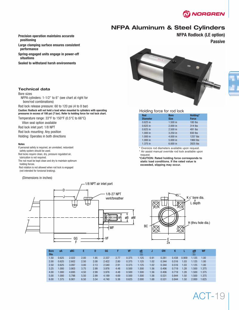
NFPA Aluminum & Steel CylindersNFPA Rodlock (LE option)
PassivePrecision operation maintains accurate
positioningLarge clamping surface ensures consistent
performanceSpring-engaged units engage in power-off
situations Sealed to withstand harsh environments
Technical dataBore sizes
NFPA cylinders: 1-1/2" to 6" (see chart at right forbore/rod combinations)
Rod lock release pressure: 60 to 120 psi (4 to 8 bar)Caution: Rodlock will not hold a load when mounted to cylinders with operatingpressures in excess of 100 psi (7 bar). Refer to holding force for rod lock chart.
Temperature range: 33°F to 150°F (0.5°C to 66°C)Viton seal option available
Rod lock inlet port: 1/8 NPTRod lock mounting: Any positionHolding: Operates in both directions
NotesIf personal safety is required, an unrelated, redundant
safety system should be used.Rod locks require clean, dry, pressure regulated air,
lubrication is not required.The rod must be kept clean and dry to maintain optimum
holding forces.Rod rotation is not allowed when rod lock is engaged (not intended for torsional braking).
Holding force for rod lockRod Bore Holding* Diameter Size Force0.625 in 1.500 in 180 lbs0.625 in 2.000 in 314 lbs0.625 in 2.500 in 491 lbs1.000 in 3.250 in 830 lbs1.000 in 4.000 in 1257 lbs1.000 in 5.000 in 1960 lbs1.375 in 6.000 in 2825 lbs
* Oversize rod diameters available upon request.* Air assist manual override rod lock available uponrequest.
*CAUTION: Rated holding force corresponds tostatic load conditions. If the rated value isexceeded, slipping may occur.
FVF
45 ˚
WF
D
J K c’ bore dia.x
L depth
E2x
BC
1/8-27 NPT vent/breather
1/8 NPT air inlet port
GG
øA øBH (thru hole dia.)
øM
Bore øA øBC E D GG F VF øB J ØH K L øM WFDia.1.50 0.625 2.022 2.00 1.95 2.337 2.77 0.375 1.125 0.91 0.281 0.438 0.909 1.125 1.002.00 0.625 2.602 2.50 2.08 2.422 2.80 0.375 1.125 1.02 0.344 0.516 1.03 1.125 1.002.50 0.625 3.097 3.00 2.13 2.540 2.91 0.375 1.125 1.02 0.344 0.516 1.03 1.125 1.003.25 1.000 3.903 3.75 2.99 3.976 4.48 0.500 1.500 1.56 0.406 0.719 1.28 1.500 1.3754.00 1.000 4.695 4.50 2.99 3.976 4.48 0.500 1.500 1.56 0.406 0.719 1.28 1.500 1.3755.00 1.000 5.798 5.50 2.99 4.189 4.69 0.500 1.500 1.56 0.531 0.844 1.50 1.500 1.3756.00 1.375 6.901 6.50 3.54 4.740 5.36 0.625 2.000 1.68 0.531 0.844 1.50 2.000 1.625
(Dimensions in inches)
-.001-.003
-.001-.003

Actuators
www.norgren.com/usaACT-20
LS Series NFPA cylinder
Improved load carrying qualitiesEcology seal improves load dampeningAlignment coupler installed in tooling plate for self-alignment ofcylinder rod to tooling plate connection prevents binding.
Technical dataNFPA tie rod cylinderBore sizes: 1-1/2" and 2"Operating pressure: 250 psi max.Temperature range: -20°F to 200°F (-29°C to 107°C)Porting: 3/8 NPTEcology piston seals available (fixed cushion, adjustable or extralong Decel-Air" cushions)Universal mounting (sleeve nut construction): Ease of cylinderremoval (modular)
Linear thruster materials of constructionBody and tooling plate: Anodized aluminum alloy.Guide rods: Hardened high carbon bearing quality steel.Bushings: Composite (Teflon lined) self-lubricating or linear rollerbearing.Felt washers: oil impregnatedRetaining rings: to ensure bearing location.Alignment coupler: carbon steel
Cylinder materials of constructionPiston rod: Chrome plated high strength carbonsteel Tie rods: High strength carbon steelSeals: Nitrile piston, piston rod and tube seals,Urethane piston rod wiper.Wearband: Teflon and graphite compositeCylinder tube: Aluminum with hardcoat anodizeRod bearing: Oil impregnated sintered ironEndcaps: A and EA Series cylinder - aluminumJ and EJ Series cylinder - steel
Decel-Air" CushionsNorgren's Decel cushioned cylinder was designed forapplications where high velocity, low mass, material function ormachine function is required, and where the kinetic energy tobe absorbed during cushioning exceeds the parameters ofstandard cylinders equipped with Ecology piston seals andfixed or adjustable cushions. Decel cushions employ longer-than-standard air cushions to assist our Impact DampeningPiston Seal.
*The weight of the cylinder piston has been deducted from the figures shown above. Note: The use of Viton® Seals limits the absorption of the impact dampening seals by 50%.** Series J & EJ onlyNOTE: The weight of a tooling plate, guide rods, and 1 extend and 1 retract stop collar has been added.(Guide rod weight is basd on a 6.0" stroke cylinder.)
Energy Absorption Capacity of the Impact Dampening Seals*Usable Pounds Stoppable at the Following Piston SpeedsThis chart features the energy absorption capacity of the impact dampening piston seals with Non-Adjustable cushions.
1-1/2" Bore 2.0" BoreLoad (LBS.) Load (LBS.) Load (LBS.) Load (LBS.)Short Body Long Body Short Body Long Body
Velocity Standard Oversize Standard Oversize Standard Oversize Standard OversizeIn./Sec Guide Shaft Guide Shaft Guide Shaft Guide Shaft Guide Shaft Guide Shaft Guide Shaft Guide Shaft
6 151.3 149.1 150.8 148.2 267.0 261.9 265.7 259.412 34.1 31.9 33.6 31.0 59.6 54.5 58.3 52.018 12.4 10.2 11.9 9.3 7.8 16.1 20.0 13.624 4.9 2.7 4.44 1.8 7.8 2.7 6.5 0.230 1.3 0 0 0 1.5 0 0.2 0.0

ACT-21
NFPA Aluminum & Steel Cylinders
21
LS
LS product ordering information
1- ProductLS Linear slide unit
3 4 5 6 7 8 921Maximum Stroke
size 3 (1-1/2" bore) size 4 (2" bore)short body 18" 22"long body 24" 28"
3 4 5 6 7 8 9
2 Size3 1-1/2"4 2"
7 - Slide Body LengthS shortL long
3 A 3 3 S S C S - Stroke - Options
OptionsAE = stroke adjustment (collar & bumper) - extend strokeAR = stroke adjustment (collar & bumper) - retract strokeCR = corrosion resistance (includes linear slide and cylinder)GL = guide rod lubrication (includes oiler cups installed)GM = guide rod lubrication modification for oiler cupsL() = non-standard port locationME = shock absorber mounting block - extend strokeMR = shock absorber mounting block- retract strokeN() = non-standard adjustable cushion needle locationP() = non-standard port size
(down one size = 1/4 NPT, up one size = 1/2 NPT)PS = magnetic piston (cylinder)PX() = tooling plate extensionTM = side tapped mountingWC = linear thruster assembly without cylinderWS = replacement cylinder without slideV = high temperature viton seals
Dimension Size 3 (1-1/2" Bore) Size 4 (2" Bore)Long body Short body Long body Short body
A 1.200 1.200 1.450 1.450AA 2.375 NA 3.125 NAB 5.765 3.650 8.000 5.000BD 7.375 5.150 8.385 5.385C 0.160 0.160 0.175 0.175BC 5.925 3.810 8.175 5.175D 1.450 1.340 0.385 0.385E 3.750 1.500 4.760 1.760EE 3/8 NPT 3/8 NPT 3/8 NPT 3/8 NPTF 0.291 0.291 0.447 0.447FF 1/4-20 x .40 1/4-20 x .40 1/4-20 x .50 1/4-20 x .50G 0.875 0.875 1.000 1.000GG 3/8-16 x .75DP 3/8-16 x .75DP 3/8-16 x .75DP 3/8-16 x .75DPH 0.875 0.875 1.500 1.500HH .3764 x .47DP .3764 x .47DP .3764 x .50DP .3764 x .50DPJ 2.375 3.125 3.125JJ .41thru .59 C/B x .66DP .53 thru .81 C/B x .66DPK 4.000 1.750 6.000 3.000L 6.450 6.450 8.380 8.380M 5.875 5.875 7.750 7.750N (Standard) 0.750 0.750 1.000 1.000N (Oversize) 1.000 1.000 1.375 1.375P 2.000 2.000 2.500 2.500Q 1.775 1.775 2.265 2.265R 1.063 1.063 1.375 1.375T 6.550 6.550 8.500 8.500TM1* 1.313 1.313 1.500 1.500TM2* 3.125 0.875 5.000 2.000TM3* 0.350 0.350 0.375 0.375TM4* 1.500 1.500 2.000 2.000V 2.000 2.000 2.500 2.500W 1.300 1.300 1.625 1.625WW 3/8-16 3/8-16 1/2-13 1/2-13X 2.200 2.200 2.750 2.750Y 4.250 4.250 5.750 5.750Z 2.375 2.375 3.125 3.125ZZ 0.875 0.875 1.000 1.000
Dimensional data
T
J
WVX
øHH
øWW
JJ**
BD + strokeBC + stroke
EB
AF
C + strokeD + stokeØGG
øN
QEE
P
RFFF
K
HG.125 øHH
J
Y± .001
M±.001
L J
*Dimensions apply to TM option only
TM4*
TM3* TM1* TM2*
3/8-16 UNC x .65 DP.*
AA
Z
ZZ
** Only 2 mounting holes on short body
4 Cushions - Extend Stroke3 non-cushioned*5 fixed cushions7 adjustable cushions**9 decel adjustable cushions**
5 Cushions - Retract Stroke3 non-cushioned*5 fixed cushions7 adjustable cushions**9 decel adjustable cushions**
6 - Slide Body WidthS standard
8 - Guide Rod Bearing TypeCcompositeRRoller +, ++
9 - Guide Rod DiameterSstandardOoversize
* Non-cushioned cylinders will have U-cup seals as standard.Ecology seals are not available as non-cushioned.
** Standard cushion adjustment location is side 1 and adds 1" to the overall length of the cylinder per end with standard port sizes.
+ Roller bearings are not available with oversized guide rods.++ Roller bearing not available with CR (corrosion resistance) option.
3 Cylinder TypeA aluminum (NFPA tie rod)EA aluminum (NFPA tie rod Ecology SealJ steel (NFPA tie rod)EJ steel (NFPA tie rod Ecology Seal
Related Documents