National Fire Protection Association 1 Batterymarch Park, Quincy, MA 02169-7471 Phone: 617-770-3000 • Fax: 617-770-0700 • www.nfpa.org M E M O R A N D U M TO: NEC Code-Making Panel 04 FROM: Kimberly Shea DATE: December 10, 2012 SUBJECT: NFPA 70 CMP-04 ROC TC Letter Ballot (A2013) ______________________________________________________________________ The ROC letter ballot for NFPA 70 CMP-04 is attached. The ballot is for formally voting on whether or not you concur with the panel’s actions on the comments. Reasons must accompany all negative and abstention ballots. Please do not vote negatively because of editorial errors. However, please bring such errors to my attention for action. Please return your ballot as soon as possible but no later than January 11, 2013. Ballots may be returned via e-mail to [email protected] or via fax to 617-984-7070. You may also mail your ballot to the attention of Kim Shea at NFPA, 1 Batterymarch Park, Quincy, MA 02169. The return of ballots is required by the Regulations Governing Committee Projects. Attachments: Comments Letter Ballot

Welcome message from author
This document is posted to help you gain knowledge. Please leave a comment to let me know what you think about it! Share it to your friends and learn new things together.
Transcript

National Fire Protection Association 1 Batterymarch Park, Quincy, MA 02169-7471 Phone: 617-770-3000 • Fax: 617-770-0700 • www.nfpa.org
M E M O R A N D U M TO: NEC Code-Making Panel 04 FROM: Kimberly Shea DATE: December 10, 2012 SUBJECT: NFPA 70 CMP-04 ROC TC Letter Ballot (A2013)
______________________________________________________________________ The ROC letter ballot for NFPA 70 CMP-04 is attached. The ballot is for formally voting on whether or not you concur with the panel’s actions on the comments. Reasons must accompany all negative and abstention ballots. Please do not vote negatively because of editorial errors. However, please bring such errors to my attention for action. Please return your ballot as soon as possible but no later than January 11, 2013. Ballots may be returned via e-mail to [email protected] or via fax to 617-984-7070. You may also mail your ballot to the attention of Kim Shea at NFPA, 1 Batterymarch Park, Quincy, MA 02169. The return of ballots is required by the Regulations Governing Committee Projects. Attachments: Comments Letter Ballot

Comm # Log#Comm.Action
Tech.Comm. Section
Sort Listing
Seq#
44 100.Solar Photovoltaic System- ( ):A14-1 NEC-P04 A2013
1248 225.1- ( ):R24-2 NEC-P04 A2013
622 225.1, Informational Note- ( ):A34-3 NEC-P04 A2013
659 225.1, Informational Note- ( ):A44-4 NEC-P04 A2013
623 Table 225.3- ( ):A54-5 NEC-P04 A2013
660 Table 225.3- ( ):A64-6 NEC-P04 A2013
1099 225.4 Exception- ( ):R74-7 NEC-P04 A2013
1277 225.4 Exception- ( ):R84-8 NEC-P04 A2013
624 225.8- ( ):A94-9 NEC-P04 A2013
661 225.8- ( ):A104-10 NEC-P04 A2013
625 225.10- ( ):A114-11 NEC-P04 A2013
662 225.10- ( ):A124-12 NEC-P04 A2013
626 225.14- ( ):A134-13 NEC-P04 A2013
663 225.14- ( ):A144-14 NEC-P04 A2013
400 225.18- ( ):R154-15 NEC-P04 A2013
627 225.18- ( ):A164-16 NEC-P04 A2013
664 225.18- ( ):A174-17 NEC-P04 A2013
401 225.19- ( ):R184-18 NEC-P04 A2013
628 225.19- ( ):A194-19 NEC-P04 A2013
665 225.19- ( ):A204-20 NEC-P04 A2013
510 225.22- ( ):R214-21 NEC-P04 A2013
629 225.30(C)- ( ):A224-22 NEC-P04 A2013
666 225.30(C)- ( ):A234-23 NEC-P04 A2013
241 225.30(F) (New)- ( ):R244-24 NEC-P04 A2013
128 225.33(A)- ( ):A254-25 NEC-P04 A2013
129 225.38(C)- ( ):A264-26 NEC-P04 A2013
630 225.50- ( ):A274-27 NEC-P04 A2013
631 225, Part III- ( ):A284-28 NEC-P04 A2013
667 225.50- ( ):A294-29 NEC-P04 A2013
668 225, Part III- ( ):A304-30 NEC-P04 A2013
130 225.51 Exception- ( ):A314-31 NEC-P04 A2013
1552 225.52(A)- ( ):A324-32 NEC-P04 A2013
247 225.52(C)- ( ):A334-33 NEC-P04 A2013
1579 225.52(F)- ( ):R344-34 NEC-P04 A2013
1553 225.80 and 225.81 (New)- ( ):A354-35 NEC-P04 A2013
632 Figure 230.1- ( ):A364-36 NEC-P04 A2013
669 Figure 230.1- ( ):A374-37 NEC-P04 A2013
633 230.2(C)- ( ):A384-38 NEC-P04 A2013
670 230.2(C)- ( ):A394-39 NEC-P04 A2013
402 230.24- ( ):R414-41 NEC-P04 A2013
Page 1A2013Cycle

Comm # Log#Comm.Action
Tech.Comm. Section
Sort Listing
Seq#
634 230.24- ( ):A424-42 NEC-P04 A2013
671 230.24- ( ):A434-43 NEC-P04 A2013
58 230.30- ( ):A444-44 NEC-P04 A2013
1432 230.30- ( ):A454-45 NEC-P04 A2013
1601 230.40- ( ):R464-46 NEC-P04 A2013
1092 230.40 Exception No. 1- ( ):A474-47 NEC-P04 A2013
1478 230.42(A)- ( ):A484-48 NEC-P04 A2013
635 230.43- ( ):A494-49 NEC-P04 A2013
672 230.43- ( ):A504-50 NEC-P04 A2013
800 230.44- ( ):R514-51 NEC-P04 A2013
636 Table 230.51(C)- ( ):A524-52 NEC-P04 A2013
673 Table 230.51(C)- ( ):A534-53 NEC-P04 A2013
1263 230.62(C) (New)- ( ):R544-54 NEC-P04 A2013
637 230.66- ( ):A554-55 NEC-P04 A2013
674 230.66- ( ):A564-56 NEC-P04 A2013
582 230.7(D) (New)- ( ):A574-57 NEC-P04 A2013
1053 230.70- ( ):R584-58 NEC-P04 A2013
131 230.71(A)- ( ):A594-59 NEC-P04 A2013
132 230.75- ( ):A604-60 NEC-P04 A2013
638 230.82- ( ):A614-61 NEC-P04 A2013
675 230.82- ( ):A624-62 NEC-P04 A2013
870 230.82- ( ):R634-63 NEC-P04 A2013
1554 230.82(3)- ( ):A644-64 NEC-P04 A2013
639 230.95- ( ):A654-65 NEC-P04 A2013
676 230.95- ( ):A664-66 NEC-P04 A2013
640 230, Part III Title- ( ):A674-67 NEC-P04 A2013
677 230, Part III Title- ( ):A684-68 NEC-P04 A2013
840 230.201 (New)- ( ):R694-69 NEC-P04 A2013
133 230.204(A) Exception- ( ):A734-73 NEC-P04 A2013
1321 230.208, Informational Note- ( ):H744-74 NEC-P04 A2013
641 230.208(B)- ( ):A754-75 NEC-P04 A2013
678 230.208(B)- ( ):A764-76 NEC-P04 A2013
134 230.211- ( ):A774-77 NEC-P04 A2013
135 230.212- ( ):A784-78 NEC-P04 A2013
912 690.1- ( ):R794-79 NEC-P04 A2013
529 690.2- ( ):R804-80 NEC-P04 A2013
1070 690.2- ( ):APR814-81 NEC-P04 A2013
60 690.2.Solar Photovoltaic System- ( ):A824-82 NEC-P04 A2013
1198 690.4. DC to DC Converter- ( ):A834-83 NEC-P04 A2013
61 690.4(B)- ( ):A844-84 NEC-P04 A2013
Page 2A2013Cycle
Comm # Log#Comm.Action
Tech.Comm. Section
Sort Listing
Seq#
1285 690.5- ( ):APP854-85 NEC-P04 A2013
1071 690.5(A)- ( ):APR864-86 NEC-P04 A2013
1489 690.5(A)- ( ):A874-87 NEC-P04 A2013
1199 690.7- ( ):R884-88 NEC-P04 A2013
642 690.7(C)- ( ):R894-89 NEC-P04 A2013
679 690.7(C)- ( ):A904-90 NEC-P04 A2013
1382 690.7(H)- ( ):A914-91 NEC-P04 A2013
62 690.8x (New)- ( ):APR924-92 NEC-P04 A2013
63 690.9- ( ):A934-93 NEC-P04 A2013
1380 690.9- ( ):APA944-94 NEC-P04 A2013
64 690.9(A)(b)- ( ):A954-95 NEC-P04 A2013
1072 690.9(C)- ( ):APR964-96 NEC-P04 A2013
66 690.10(E)- ( ):A974-97 NEC-P04 A2013
67 690.10(E)- ( ):A984-98 NEC-P04 A2013
1073 690.11- ( ):APR994-99 NEC-P04 A2013
1158 690.11- ( ):APA1004-100 NEC-P04 A2013
1159 690.11- ( ):APA1014-101 NEC-P04 A2013
1167 690.11- ( ):R1024-102 NEC-P04 A2013
1289 690.11- ( ):H1034-103 NEC-P04 A2013
1453 690.11- ( ):R1044-104 NEC-P04 A2013
1490 690.11- ( ):APR1054-105 NEC-P04 A2013
1066 690.12 (New)- ( ):R1064-106 NEC-P04 A2013
1286 690.12- ( ):APR1074-107 NEC-P04 A2013
1352 690.12 (New)- ( ):APP1084-108 NEC-P04 A2013
1454 690.12- ( ):R1094-109 NEC-P04 A2013
1491 690.12- ( ):APR1104-110 NEC-P04 A2013
1497 690.12- ( ):R1114-111 NEC-P04 A2013
1498 690.12- ( ):R1124-112 NEC-P04 A2013
1505 690.12- ( ):A1134-113 NEC-P04 A2013
68 690.13- ( ):A1144-114 NEC-P04 A2013
1606 690.13 and 690.15- ( ):R1154-115 NEC-P04 A2013
1607 690.13 and 690.15- ( ):R1164-116 NEC-P04 A2013
11 690.14(4), Informational Note- ( ):R1174-117 NEC-P04 A2013
69 690.14(A)- ( ):A1184-118 NEC-P04 A2013
156 690.14(C)(4)- ( ):A1194-119 NEC-P04 A2013
13 690.14(D)(1)- ( ):R1204-120 NEC-P04 A2013
14 690.14(D)(1)- ( ):R1214-121 NEC-P04 A2013
15 690.14(D)(1)- ( ):R1224-122 NEC-P04 A2013
1361 690.14(D)(1)- ( ):R1234-123 NEC-P04 A2013
70 690.15- ( ):A1244-124 NEC-P04 A2013
Page 3A2013Cycle
Comm # Log#Comm.Action
Tech.Comm. Section
Sort Listing
Seq#
1168 690.15- ( ):R1254-125 NEC-P04 A2013
1381 690.15(C)- ( ):R1264-126 NEC-P04 A2013
71 690.15(C)(4)- ( ):A1274-127 NEC-P04 A2013
72 690.17- ( ):A1284-128 NEC-P04 A2013
836 690.17- ( ):APP1294-129 NEC-P04 A2013
1169 690.17- ( ):APA1304-130 NEC-P04 A2013
73 690.17(4)- ( ):A1314-131 NEC-P04 A2013
74 690.31- ( ):A1324-132 NEC-P04 A2013
1170 690.31- ( ):R1334-133 NEC-P04 A2013
1074 690.31(B)- ( ):R1344-134 NEC-P04 A2013
1075 690.31(C)(1)- ( ):APR1354-135 NEC-P04 A2013
1511 690.31(C)(1)- ( ):APP1364-136 NEC-P04 A2013
1171 690.31(E)- ( ):R1374-137 NEC-P04 A2013
1291 690.31(E)- ( ):R1384-138 NEC-P04 A2013
1287 690.35- ( ):APP1394-139 NEC-P04 A2013
1076 690.35(C)- ( ):APR1404-140 NEC-P04 A2013
1492 690.35(C)- ( ):A1414-141 NEC-P04 A2013
1081 690.35(D)- ( ):A1424-142 NEC-P04 A2013
75 690.35(D)(1)- ( ):A1434-143 NEC-P04 A2013
76 690.41- ( ):A1444-144 NEC-P04 A2013
1077 690.41- ( ):APR1454-145 NEC-P04 A2013
1290 690.41- ( ):R1464-146 NEC-P04 A2013
1493 690.41- ( ):APR1474-147 NEC-P04 A2013
899 690.43(E)- ( ):R1484-148 NEC-P04 A2013
1234 690.45- ( ):APR1494-149 NEC-P04 A2013
77 690.46- ( ):A1504-150 NEC-P04 A2013
78 690.47(B), 690.47(C)(3)- ( ):APR1514-151 NEC-P04 A2013
277 690.47(B) and 690.47(C)(3)- ( ):APR1524-152 NEC-P04 A2013
79 690.47(C)(2)- ( ):APR1534-153 NEC-P04 A2013
530 690.47(C)(2)- ( ):A1544-154 NEC-P04 A2013
1001 690.47(D)- ( ):A1554-155 NEC-P04 A2013
1078 690.47(D)- ( ):APP1564-156 NEC-P04 A2013
1200 690.47(D)- ( ):APR1574-157 NEC-P04 A2013
1201 690.47(D)- ( ):R1584-158 NEC-P04 A2013
1506 690.56(B)- ( ):APP1594-159 NEC-P04 A2013
80 690.71 (New)- ( ):A1604-160 NEC-P04 A2013
81 690.71- ( ):A1614-161 NEC-P04 A2013
643 690.80- ( ):A1624-162 NEC-P04 A2013
644 690, Part IX Title- ( ):A1634-163 NEC-P04 A2013
680 690.80- ( ):A1644-164 NEC-P04 A2013
Page 4A2013Cycle

Comm # Log#Comm.Action
Tech.Comm. Section
Sort Listing
Seq#
681 690, Part IX Title- ( ):A1654-165 NEC-P04 A2013
1288 690.80- ( ):R1664-166 NEC-P04 A2013
463 692.2.Fuel Cell- ( ):A1674-167 NEC-P04 A2013
464 692.2.Fuel Cell System- ( ):A1684-168 NEC-P04 A2013
465 692.2.Output Circuit and Informational Note- ( ):A1694-169 NEC-P04 A2013
645 692.80- ( ):A1704-170 NEC-P04 A2013
646 692, Part VIII Title- ( ):A1714-171 NEC-P04 A2013
682 692.80- ( ):A1724-172 NEC-P04 A2013
683 692, Part VIII Title- ( ):A1734-173 NEC-P04 A2013
466 694.2.Rated Power- ( ):APP1744-174 NEC-P04 A2013
82 694.7(B)- ( ):A1754-175 NEC-P04 A2013
83 694.7(B)- ( ):A1764-176 NEC-P04 A2013
1455 694.7(B)- ( ):APR1774-177 NEC-P04 A2013
1456 694.7(B)- ( ):APR1784-178 NEC-P04 A2013
84 694.7(E)- ( ):A1794-179 NEC-P04 A2013
1573 694.7(E)- ( ):A1804-180 NEC-P04 A2013
647 694.10(A)- ( ):R1814-181 NEC-P04 A2013
684 694.10(A)- ( ):A1824-182 NEC-P04 A2013
157 694.22(C)(4)- ( ):A1834-183 NEC-P04 A2013
531 694.23- ( ):R1844-184 NEC-P04 A2013
85 694.40- ( ):A1854-185 NEC-P04 A2013
278 694.40- ( ):APP1864-186 NEC-P04 A2013
648 694.80- ( ):A1874-187 NEC-P04 A2013
649 694, Part IX- ( ):A1884-188 NEC-P04 A2013
685 694.80- ( ):A1894-189 NEC-P04 A2013
686 694, Part IX- ( ):A1904-190 NEC-P04 A2013
86 696 (New)- ( ):A1914-191 NEC-P04 A2013
1079 696 (New)- ( ):A1924-192 NEC-P04 A2013
1383 696 (New)- ( ):A1934-193 NEC-P04 A2013
87 702.12(D)- ( ):A1944-194 NEC-P04 A2013
88 705.2- ( ):A1954-195 NEC-P04 A2013
1035 705.2- ( ):A1964-196 NEC-P04 A2013
1080 705.12- ( ):R1974-197 NEC-P04 A2013
10 705.12(A)- ( ):R1984-198 NEC-P04 A2013
161 705.12(D)- ( ):A1994-199 NEC-P04 A2013
1575 705.12(D)- ( ):R2004-200 NEC-P04 A2013
12 705.12(D)(2)- ( ):R2014-201 NEC-P04 A2013
871 705.12(D)(2)(c)- ( ):R2024-202 NEC-P04 A2013
1507 705.12(D)(2)(b) Exception- ( ):A2034-203 NEC-P04 A2013
1603 705.12(D)(2)- ( ):APR2044-204 NEC-P04 A2013
Page 5A2013Cycle

Comm # Log#Comm.Action
Tech.Comm. Section
Sort Listing
Seq#
9 705.12(D)(2) Exception- ( ):R2054-205 NEC-P04 A2013
1508 705.12(D)(6)- ( ):A2064-206 NEC-P04 A2013
1384 705.30 and 705.31 (New)- ( ):R2074-207 NEC-P04 A2013
89 705.31 (New)- ( ):A2084-208 NEC-P04 A2013
1509 705.100- ( ):APR2094-209 NEC-P04 A2013
Page 6A2013Cycle

Report on Comments – June 2013 NFPA 70_______________________________________________________________________________________________4-1 Log #44 NEC-P04
_______________________________________________________________________________________________Technical Correlating Committee on National Electrical Code®,
4-8aThe Correlating Committee directs that the panel clarify the panel action on this proposal to
correlate with the panel action on Proposal 4-184 and determine the placement of the definition, Article 100 or 690.2.
This is a direction from the National Electrical Code Technical Correlating Committee in accordancewith 3.4.2 and 3.4.3 of the Regulations Governing Committee Projects.
Move definition of solar photovoltaic system to Article 100.
_______________________________________________________________________________________________4-2 Log #1248 NEC-P04
_______________________________________________________________________________________________John Masarick, Independent Electrical Contractors, Inc.
4-11Reject this proposal which would change 600 volts to 1000 volts.
Replacing 600 volts with 1000 volts will have a major impact on installers, component manufacturers,and industry standards. Increased spacing must be considered when going from 600 volts to 1000 volts. Personalsafety must also be considered.Because the proposer has not provided enough information to the public to justify and understand all the ramifications ofthe proposal, the committee should continue to reject the submitter’s proposal.
The acceptance of the original proposal does not mandate that all equipment and systems beoperated at the elevated voltage but rather allows the operation at a higher level if necessary. This change is necessaryto keep pace with changes in technology.
1Printed on 12/10/2012

Report on Comments – June 2013 NFPA 70_______________________________________________________________________________________________4-3 Log #622 NEC-P04
_______________________________________________________________________________________________James T. Dollard, Jr., IBEW Local 98
4-11Continue to Accept in Principle.
This comment is submitted by a single individual and does not represent the work or input of the highvoltage task group (HVTG). This comment attempts to address concerns stated in the negative. Safety of all electricalworkers must be the first consideration when the technical committee considers raising the voltage threshold. Thissubmitter greatly appreciates the technical committee members concern for the safety of all electrical workers. I havereviewed the impact on worker safety in each of these proposals. As the safety coordinator for IBEW Local 98 inPhiladelphia, I could not support raising the voltage threshold if I felt there was a safety concern that we could notaddress. If there is any concern that the safety of electrical workers is impacted, CMP-4 should reject all proposalsseeking to raise the voltage threshold.
The work of the high voltage task group was very broad in nature. It is widely recognized and understood thatemerging technologies such as small wind and PV are breaking the 600-volt threshold making these alternative energysources more efficient. The HVTG was directed to review this issue and to submit proposals to generate a shift in NECrequirements to specifically address these new system voltages. The HVTG submitted proposals to the technicalcommittees with specific expertise to let each individual CMP make the decision on raising the voltage threshold. Weneeded a placeholder in all locations. Any CMP that felt there was a safety issue rejected the proposal. The HVTGsupported those rejections in each case. The final decision lies with the technical committee.
It is important to note that if this technical committee raises the voltage threshold from 600 to 1000-volts in the NEC,the only change is the “ voltage threshold level” of the installation requirement. This change in the voltage thresholdlevel does not permit conductors and equipment rated at 600-volts to be used at 1000-volts. That would require theconductors and equipment to be tested and listed for such use. See NFPA 70 110.3(B). There are many products thatare already listed and marked for this use.
NFPA 70E requires that all employees who face a risk of electrical hazard that is not reduced to a safe level by theapplicable electrical installation requirements be trained to understand the specific hazards they face. See 70E 110.2.Qualified persons are required. Energized work is only permitted where justified. See 130.2. Personal Protectiveequipment, including but not limited to voltage rated gloves and arc rated clothing are readily available. Trainingprograms for electrical safe work practices for voltages over 600-volts are readily available.
There are meters and other test instruments readily available for use to day at 1000-volts. It should be noted thatNFPA 70E 110.4 requires all test instruments to be properly rated and used only by qualified persons. NFPA 70E110.2(D)(1)(4)(e) requires the qualified person be trained on the proper use and limitations of the test instrument. Aquick Google search revealed the following, there are more:
Fluke 77IV, general purpose digital meter, 1000-vac, 1000-vdcIdeal 490, general-purpose digital meter, 1000-vac, 1000-vdcIn closing, I would like to repeat that if there is any concern that the safety of electrical workers is impacted, CMP-4
should reject all proposals seeking to raise the voltage threshold.
2Printed on 12/10/2012

Report on Comments – June 2013 NFPA 70_______________________________________________________________________________________________4-4 Log #659 NEC-P04
_______________________________________________________________________________________________James T. Dollard, Jr., IBEW Local 98
4-11Continue to Accept in Principle.
This comment is submitted on behalf of the high voltage task group to provide additional substantiationas directed by the Correlating Committee.
The High Voltage Task Group (HVTG) was charged with developing recommendations throughout the NEC to providethe code user with prescriptive requirements for high voltage installations. The task group charge was to identify holes inthe code with respect to installations operating at over 600-volts and address them with recommended requirements toallow for uniform installation and enforcement. Small Wind Electric Systems and Solar Photovoltaic (PV) Systems arecurrently being installed at DC voltages over 600V up to and including 1000V, 1200V, 1500V, and 2000V DC. TheseDC systems are expanding and have become a more integral part of many structures. Small Wind Electric Systems andSolar Photovoltaic (PV) Systems are employed regularly in, and on all types of structures from dwellings units, to largeretail and high rise construction.
The first direction that the HVTG took was to simply suggest revisions in Chapter 6 for Special Equipment. It isextremely important to fully understand the outline form of the NEC. 90.3 mandates that Chapters 1 through 4 applygenerally and Chapters 5, 6 & 7 are special and serve only to modify or supplement the rules in Chapters 1 through 4.The HVTG quickly realized that it was not feasible to address all of the installation requirements in Chapter 6. The workneeds to be done throughout the NEC. The special systems in Chapter 6 are built primarily upon Chapters 1 through 4with the Chapter 6 requirements providing only modifications or supplemental requirements. A quick review of the ULWhite-book for electrical products will uncover that UL has many products that are utilized in these systems rated at andabove 600-volts including but not limited to, 600Vdc terminal blocks, 1000Vdc PV switches, 1500Vdc PV fuses, and2000V PV wiring. Product listings provide permitted uses and restrictions on a given product. The NEC must recognizethose products through installation requirements. Electrical safety in the home, workplace and in all venues dependsupon installation requirements to ensure that all persons and property are not exposed to the hazards of electricity. Thesuccess of this code hinges on three things (1) product standards, (2) installation requirements and (3) enforcement.The NEC needs to recognize emerging technologies that are operating at over 600-volts. Everyone needs to play a rolein this transition. The present NEC requirements would literally require that a PV system operating at 750-volts DCutilize a disconnecting means rated at 5 kV. The manufacturers, research and testing laboratories and the NEC mustwork together to develop installation requirements and product standards to support these emerging technologies.
Moving the NEC threshold from 600 volts to 1000 volts will not, by itself, allow the immediate installation of systems at1000-volts. Equipment must first be tested and found acceptable for use at the higher voltage(s). The testing and listingof equipment will not, by itself, allow for the installation of 1000 volt-systems. The NEC must include prescriptiverequirements to permit the installation of these 1000-volt systems. It will take both tested/listed equipment and aninstallation code to meet the needs of these emerging technologies that society demands. The installation code shouldbe the NEC.
Moving the NEC to 1000 volts is just the beginning. The desire to keep increasing efficiencies will continue to drive upthe system voltages. We are beginning to see 1200, 1500, and 2000-volt systems. 2500 volts cannot be far down theroad. Most equipment standards are still at 600 volts and will need to be upgraded also.
If the NEC does not adequately address systems over 600 volts, some other standard will. If we want to control thefuture safety of installations over 600 volts we need to address these issues today.
3Printed on 12/10/2012

Report on Comments – June 2013 NFPA 70_______________________________________________________________________________________________4-5 Log #623 NEC-P04
_______________________________________________________________________________________________James T. Dollard, Jr., IBEW Local 98
4-14Continue to Accept in Principle.
This comment is submitted by a single individual and does not represent the work or input of the highvoltage task group (HVTG). This comment attempts to address concerns stated in the negative. Safety of all electricalworkers must be the first consideration when the technical committee considers raising the voltage threshold. Thissubmitter greatly appreciates the technical committee members concern for the safety of all electrical workers. I havereviewed the impact on worker safety in each of these proposals. As the safety coordinator for IBEW Local 98 inPhiladelphia, I could not support raising the voltage threshold if I felt there was a safety concern that we could notaddress. If there is any concern that the safety of electrical workers is impacted, CMP-4 should reject all proposalsseeking to raise the voltage threshold.
The work of the high voltage task group was very broad in nature. It is widely recognized and understood thatemerging technologies such as small wind and PV are breaking the 600-volt threshold making these alternative energysources more efficient. The HVTG was directed to review this issue and to submit proposals to generate a shift in NECrequirements to specifically address these new system voltages. The HVTG submitted proposals to the technicalcommittees with specific expertise to let each individual CMP make the decision on raising the voltage threshold. Weneeded a placeholder in all locations. Any CMP that felt there was a safety issue rejected the proposal. The HVTGsupported those rejections in each case. The final decision lies with the technical committee.
It is important to note that if this technical committee raises the voltage threshold from 600 to 1000-volts in the NEC,the only change is the “ voltage threshold level” of the installation requirement. This change in the voltage thresholdlevel does not permit conductors and equipment rated at 600-volts to be used at 1000-volts. That would require theconductors and equipment to be tested and listed for such use. See NFPA 70 110.3(B). There are many products thatare already listed and marked for this use.
NFPA 70E requires that all employees who face a risk of electrical hazard that is not reduced to a safe level by theapplicable electrical installation requirements be trained to understand the specific hazards they face. See 70E 110.2.Qualified persons are required. Energized work is only permitted where justified. See 130.2. Personal Protectiveequipment, including but not limited to voltage rated gloves and arc rated clothing are readily available. Trainingprograms for electrical safe work practices for voltages over 600-volts are readily available.
There are meters and other test instruments readily available for use to day at 1000-volts. It should be noted thatNFPA 70E 110.4 requires all test instruments to be properly rated and used only by qualified persons. NFPA 70E110.2(D)(1)(4)(e) requires the qualified person be trained on the proper use and limitations of the test instrument. Aquick Google search revealed the following, there are more:
Fluke 77IV, general purpose digital meter, 1000-vac, 1000-vdcIdeal 490, general-purpose digital meter, 1000-vac, 1000-vdcIn closing, I would like to repeat that if there is any concern that the safety of electrical workers is impacted, CMP-4
should reject all proposals seeking to raise the voltage threshold.
4Printed on 12/10/2012

Report on Comments – June 2013 NFPA 70_______________________________________________________________________________________________4-6 Log #660 NEC-P04
_______________________________________________________________________________________________James T. Dollard, Jr., IBEW Local 98
4-14Continue to Accept in Principle.
This comment is submitted on behalf of the high voltage task group to provide additional substantiationas directed by the Correlating Committee.
The High Voltage Task Group (HVTG) was charged with developing recommendations throughout the NEC to providethe code user with prescriptive requirements for high voltage installations. The task group charge was to identify holes inthe code with respect to installations operating at over 600-volts and address them with recommended requirements toallow for uniform installation and enforcement. Small Wind Electric Systems and Solar Photovoltaic (PV) Systems arecurrently being installed at DC voltages over 600V up to and including 1000V, 1200V, 1500V, and 2000V DC. TheseDC systems are expanding and have become a more integral part of many structures. Small Wind Electric Systems andSolar Photovoltaic (PV) Systems are employed regularly in, and on all types of structures from dwellings units, to largeretail and high rise construction.
The first direction that the HVTG took was to simply suggest revisions in Chapter 6 for Special Equipment. It isextremely important to fully understand the outline form of the NEC. 90.3 mandates that Chapters 1 through 4 applygenerally and Chapters 5, 6 & 7 are special and serve only to modify or supplement the rules in Chapters 1 through 4.The HVTG quickly realized that it was not feasible to address all of the installation requirements in Chapter 6. The workneeds to be done throughout the NEC. The special systems in Chapter 6 are built primarily upon Chapters 1 through 4with the Chapter 6 requirements providing only modifications or supplemental requirements. A quick review of the ULWhite-book for electrical products will uncover that UL has many products that are utilized in these systems rated at andabove 600-volts including but not limited to, 600Vdc terminal blocks, 1000Vdc PV switches, 1500Vdc PV fuses, and2000V PV wiring. Product listings provide permitted uses and restrictions on a given product. The NEC must recognizethose products through installation requirements. Electrical safety in the home, workplace and in all venues dependsupon installation requirements to ensure that all persons and property are not exposed to the hazards of electricity. Thesuccess of this code hinges on three things (1) product standards, (2) installation requirements and (3) enforcement.The NEC needs to recognize emerging technologies that are operating at over 600-volts. Everyone needs to play a rolein this transition. The present NEC requirements would literally require that a PV system operating at 750-volts DCutilize a disconnecting means rated at 5 kV. The manufacturers, research and testing laboratories and the NEC mustwork together to develop installation requirements and product standards to support these emerging technologies.
Moving the NEC threshold from 600 volts to 1000 volts will not, by itself, allow the immediate installation of systems at1000-volts. Equipment must first be tested and found acceptable for use at the higher voltage(s). The testing and listingof equipment will not, by itself, allow for the installation of 1000 volt-systems. The NEC must include prescriptiverequirements to permit the installation of these 1000-volt systems. It will take both tested/listed equipment and aninstallation code to meet the needs of these emerging technologies that society demands. The installation code shouldbe the NEC.
Moving the NEC to 1000 volts is just the beginning. The desire to keep increasing efficiencies will continue to drive upthe system voltages. We are beginning to see 1200, 1500, and 2000-volt systems. 2500 volts cannot be far down theroad. Most equipment standards are still at 600 volts and will need to be upgraded also.
If the NEC does not adequately address systems over 600 volts, some other standard will. If we want to control thefuture safety of installations over 600 volts we need to address these issues today.
5Printed on 12/10/2012

Report on Comments – June 2013 NFPA 70_______________________________________________________________________________________________4-7 Log #1099 NEC-P04
_______________________________________________________________________________________________John Sigmund, American Chemical Council
4-16Revise text to read as follows:
225.4
The term Equipment Grounding Conductor needs to be replaced. Those opposed have no technicalreason for their opposition or any other valid reason. It is not worth the effort and everyone understands what is meantare common responses.
It is very simple: Grounding electrode conductors are the connection to the earth and accomplish grounding. In thepresent NEC, Equipment Grounding Conductors and bonding jumpers provide a "path back" to the source. Both arealways performing a bonding function. If the Grounding Electrode connection is removed or broken, the bonding functionremains intact.
Section 250.4 does not permit the earth (ground) to be used as an effective ground fault current path but the termequipment grounding conductor inherently incorrectly contains the word "ground".
Visualize equipment supplied by a portable generator. The generator frame is not required to be connected to theearth.
The "green" wire in the flexible cord is not performing a grounding function but is performing a bonding function.Visualize building one supplied by a service, having the grounded conductor connected to the grounding electrode
system by a grounding electrode conductor. A feeder supplies a second building and a grounding electrode conductor isrequired for grounding any equipment in the second building. An equipment grounding conductor is required to beinstalled from building 1 to building 2. Not for grounding, but for bonding, providing an effective fault current path.
Making this change has the added benefit of being more harmonized with other international standards and usage ofterminology.
Experienced NEC users have to ignore other concepts in other definitions and requirements to use the existing term.This does not help the future NEC user or provide clarity in the existing NEC. Changing the term is the right thing to do
and should be supported.
The term, equipment grounding conductor (EGC), is used throughout the code and is wellunderstood. Making this change in 225.4 will conflict with the use of EGC throughout the code.
6Printed on 12/10/2012

Report on Comments – June 2013 NFPA 70_______________________________________________________________________________________________4-8 Log #1277 NEC-P04
_______________________________________________________________________________________________Elliot Rappaport, Electro Technology Consultants
4-16Accept proposal.
The term “equipment grounding conductor” is not well understood as evidenced by the number ofquestions raised at inspectors’ code sessions and code classes
The term “equipment grounding conductor” has a definite purpose that is not uniquely expressed in the term, i.e. “bondthe equipment to a terminal at the source of voltage”. As a result, there is a misconception that “grounding”, withoutbonding to the source, will make a system safe. On the contrary, connecting equipment to ground without providing thebonding connection back to the source can make equipment less safe by increasing the time to clear the fault.
There is generally insufficient significance placed on the importance of bonding over grounding. Bonding providessufficient ground fault current back to the source of voltage to operate an overcurrent device and clear the fault quickly.Connection to ground limits the voltage to ground on normally non-current-carrying parts during non-fault conditions.During fault conditions, the value of grounding is minimal since the primary safety concern is to remove the fault voltageas quickly as possible. A path to ground for fault current is not necessary since ground fault current must return to thesource of voltage, not to ground.
Renaming this conductor as an “Equipment Bonding Conductor (EBC)” will clarify that the primary purpose of thisconductor is to bond to the source in order to provide a known path for ground fault current that will facilitate rapid faultclearing.
It is recognized that the term “EGC” has been in use for a long time and that changing it to EBC will cause someconcerns including changing written literature that uses the EGC term. After the initial period of understanding, users willcorrectly understand the purpose of this conductor and this will enhance the safety of personnel.
The fundamental purpose of this and companion proposals is to clearly state that “systems” are “grounded” and“equipment” is “bonded”. The fact that the bonding conductor may be grounded also is secondary to the primaryfunction of bonding.
The term, equipment grounding conductor (EGC), is used throughout the code and is wellunderstood. Making this change in 225.4 will conflict with the use of EGC throughout the code.
7Printed on 12/10/2012

Report on Comments – June 2013 NFPA 70_______________________________________________________________________________________________4-9 Log #624 NEC-P04
_______________________________________________________________________________________________James T. Dollard, Jr., IBEW Local 98
4-18Continue to Accept in Principle.
This comment is submitted by a single individual and does not represent the work or input of the highvoltage task group (HVTG). This comment attempts to address concerns stated in the negative. Safety of all electricalworkers must be the first consideration when the technical committee considers raising the voltage threshold. Thissubmitter greatly appreciates the technical committee members concern for the safety of all electrical workers. I havereviewed the impact on worker safety in each of these proposals. As the safety coordinator for IBEW Local 98 inPhiladelphia, I could not support raising the voltage threshold if I felt there was a safety concern that we could notaddress. If there is any concern that the safety of electrical workers is impacted, CMP-4 should reject all proposalsseeking to raise the voltage threshold.
The work of the high voltage task group was very broad in nature. It is widely recognized and understood thatemerging technologies such as small wind and PV are breaking the 600-volt threshold making these alternative energysources more efficient. The HVTG was directed to review this issue and to submit proposals to generate a shift in NECrequirements to specifically address these new system voltages. The HVTG submitted proposals to the technicalcommittees with specific expertise to let each individual CMP make the decision on raising the voltage threshold. Weneeded a placeholder in all locations. Any CMP that felt there was a safety issue rejected the proposal. The HVTGsupported those rejections in each case. The final decision lies with the technical committee.
It is important to note that if this technical committee raises the voltage threshold from 600 to 1000-volts in the NEC,the only change is the “ voltage threshold level” of the installation requirement. This change in the voltage thresholdlevel does not permit conductors and equipment rated at 600-volts to be used at 1000-volts. That would require theconductors and equipment to be tested and listed for such use. See NFPA 70 110.3(B). There are many products thatare already listed and marked for this use.
NFPA 70E requires that all employees who face a risk of electrical hazard that is not reduced to a safe level by theapplicable electrical installation requirements be trained to understand the specific hazards they face. See 70E 110.2.Qualified persons are required. Energized work is only permitted where justified. See 130.2. Personal Protectiveequipment, including but not limited to voltage rated gloves and arc rated clothing are readily available. Trainingprograms for electrical safe work practices for voltages over 600-volts are readily available.
There are meters and other test instruments readily available for use to day at 1000-volts. It should be noted thatNFPA 70E 110.4 requires all test instruments to be properly rated and used only by qualified persons. NFPA 70E110.2(D)(1)(4)(e) requires the qualified person be trained on the proper use and limitations of the test instrument. Aquick Google search revealed the following, there are more:
Fluke 77IV, general purpose digital meter, 1000-vac, 1000-vdcIdeal 490, general-purpose digital meter, 1000-vac, 1000-vdcIn closing, I would like to repeat that if there is any concern that the safety of electrical workers is impacted, CMP-4
should reject all proposals seeking to raise the voltage threshold.
8Printed on 12/10/2012

Report on Comments – June 2013 NFPA 70_______________________________________________________________________________________________4-10 Log #661 NEC-P04
_______________________________________________________________________________________________James T. Dollard, Jr., IBEW Local 98
4-18Continue to Accept in Principle.
This comment is submitted on behalf of the high voltage task group to provide additional substantiationas directed by the Correlating Committee.
The High Voltage Task Group (HVTG) was charged with developing recommendations throughout the NEC to providethe code user with prescriptive requirements for high voltage installations. The task group charge was to identify holes inthe code with respect to installations operating at over 600-volts and address them with recommended requirements toallow for uniform installation and enforcement. Small Wind Electric Systems and Solar Photovoltaic (PV) Systems arecurrently being installed at DC voltages over 600V up to and including 1000V, 1200V, 1500V, and 2000V DC. TheseDC systems are expanding and have become a more integral part of many structures. Small Wind Electric Systems andSolar Photovoltaic (PV) Systems are employed regularly in, and on all types of structures from dwellings units, to largeretail and high rise construction.
The first direction that the HVTG took was to simply suggest revisions in Chapter 6 for Special Equipment. It isextremely important to fully understand the outline form of the NEC. 90.3 mandates that Chapters 1 through 4 applygenerally and Chapters 5, 6 & 7 are special and serve only to modify or supplement the rules in Chapters 1 through 4.The HVTG quickly realized that it was not feasible to address all of the installation requirements in Chapter 6. The workneeds to be done throughout the NEC. The special systems in Chapter 6 are built primarily upon Chapters 1 through 4with the Chapter 6 requirements providing only modifications or supplemental requirements. A quick review of the ULWhite-book for electrical products will uncover that UL has many products that are utilized in these systems rated at andabove 600-volts including but not limited to, 600Vdc terminal blocks, 1000Vdc PV switches, 1500Vdc PV fuses, and2000V PV wiring. Product listings provide permitted uses and restrictions on a given product. The NEC must recognizethose products through installation requirements. Electrical safety in the home, workplace and in all venues dependsupon installation requirements to ensure that all persons and property are not exposed to the hazards of electricity. Thesuccess of this code hinges on three things (1) product standards, (2) installation requirements and (3) enforcement.The NEC needs to recognize emerging technologies that are operating at over 600-volts. Everyone needs to play a rolein this transition. The present NEC requirements would literally require that a PV system operating at 750-volts DCutilize a disconnecting means rated at 5 kV. The manufacturers, research and testing laboratories and the NEC mustwork together to develop installation requirements and product standards to support these emerging technologies.
Moving the NEC threshold from 600 volts to 1000 volts will not, by itself, allow the immediate installation of systems at1000-volts. Equipment must first be tested and found acceptable for use at the higher voltage(s). The testing and listingof equipment will not, by itself, allow for the installation of 1000 volt-systems. The NEC must include prescriptiverequirements to permit the installation of these 1000-volt systems. It will take both tested/listed equipment and aninstallation code to meet the needs of these emerging technologies that society demands. The installation code shouldbe the NEC.
Moving the NEC to 1000 volts is just the beginning. The desire to keep increasing efficiencies will continue to drive upthe system voltages. We are beginning to see 1200, 1500, and 2000-volt systems. 2500 volts cannot be far down theroad. Most equipment standards are still at 600 volts and will need to be upgraded also.
If the NEC does not adequately address systems over 600 volts, some other standard will. If we want to control thefuture safety of installations over 600 volts we need to address these issues today.
9Printed on 12/10/2012

Report on Comments – June 2013 NFPA 70_______________________________________________________________________________________________4-11 Log #625 NEC-P04
_______________________________________________________________________________________________James T. Dollard, Jr., IBEW Local 98
4-19Continue to Accept in Principle.
This comment is submitted by a single individual and does not represent the work or input of the highvoltage task group (HVTG). This comment attempts to address concerns stated in the negative. Safety of all electricalworkers must be the first consideration when the technical committee considers raising the voltage threshold. Thissubmitter greatly appreciates the technical committee members concern for the safety of all electrical workers. I havereviewed the impact on worker safety in each of these proposals. As the safety coordinator for IBEW Local 98 inPhiladelphia, I could not support raising the voltage threshold if I felt there was a safety concern that we could notaddress. If there is any concern that the safety of electrical workers is impacted, CMP-4 should reject all proposalsseeking to raise the voltage threshold.
The work of the high voltage task group was very broad in nature. It is widely recognized and understood thatemerging technologies such as small wind and PV are breaking the 600-volt threshold making these alternative energysources more efficient. The HVTG was directed to review this issue and to submit proposals to generate a shift in NECrequirements to specifically address these new system voltages. The HVTG submitted proposals to the technicalcommittees with specific expertise to let each individual CMP make the decision on raising the voltage threshold. Weneeded a placeholder in all locations. Any CMP that felt there was a safety issue rejected the proposal. The HVTGsupported those rejections in each case. The final decision lies with the technical committee.
It is important to note that if this technical committee raises the voltage threshold from 600 to 1000-volts in the NEC,the only change is the “ voltage threshold level” of the installation requirement. This change in the voltage thresholdlevel does not permit conductors and equipment rated at 600-volts to be used at 1000-volts. That would require theconductors and equipment to be tested and listed for such use. See NFPA 70 110.3(B). There are many products thatare already listed and marked for this use.
NFPA 70E requires that all employees who face a risk of electrical hazard that is not reduced to a safe level by theapplicable electrical installation requirements be trained to understand the specific hazards they face. See 70E 110.2.Qualified persons are required. Energized work is only permitted where justified. See 130.2. Personal Protectiveequipment, including but not limited to voltage rated gloves and arc rated clothing are readily available. Trainingprograms for electrical safe work practices for voltages over 600-volts are readily available.
There are meters and other test instruments readily available for use to day at 1000-volts. It should be noted thatNFPA 70E 110.4 requires all test instruments to be properly rated and used only by qualified persons. NFPA 70E110.2(D)(1)(4)(e) requires the qualified person be trained on the proper use and limitations of the test instrument. Aquick Google search revealed the following, there are more:
Fluke 77IV, general purpose digital meter, 1000-vac, 1000-vdcIdeal 490, general-purpose digital meter, 1000-vac, 1000-vdcIn closing, I would like to repeat that if there is any concern that the safety of electrical workers is impacted, CMP-4
should reject all proposals seeking to raise the voltage threshold.
10Printed on 12/10/2012

Report on Comments – June 2013 NFPA 70_______________________________________________________________________________________________4-12 Log #662 NEC-P04
_______________________________________________________________________________________________James T. Dollard, Jr., IBEW Local 98
4-19Continue to Accept in Principle.
This comment is submitted on behalf of the high voltage task group to provide additional substantiationas directed by the Correlating Committee.
The High Voltage Task Group (HVTG) was charged with developing recommendations throughout the NEC to providethe code user with prescriptive requirements for high voltage installations. The task group charge was to identify holes inthe code with respect to installations operating at over 600-volts and address them with recommended requirements toallow for uniform installation and enforcement. Small Wind Electric Systems and Solar Photovoltaic (PV) Systems arecurrently being installed at DC voltages over 600V up to and including 1000V, 1200V, 1500V, and 2000V DC. TheseDC systems are expanding and have become a more integral part of many structures. Small Wind Electric Systems andSolar Photovoltaic (PV) Systems are employed regularly in, and on all types of structures from dwellings units, to largeretail and high rise construction.
The first direction that the HVTG took was to simply suggest revisions in Chapter 6 for Special Equipment. It isextremely important to fully understand the outline form of the NEC. 90.3 mandates that Chapters 1 through 4 applygenerally and Chapters 5, 6 & 7 are special and serve only to modify or supplement the rules in Chapters 1 through 4.The HVTG quickly realized that it was not feasible to address all of the installation requirements in Chapter 6. The workneeds to be done throughout the NEC. The special systems in Chapter 6 are built primarily upon Chapters 1 through 4with the Chapter 6 requirements providing only modifications or supplemental requirements. A quick review of the ULWhite-book for electrical products will uncover that UL has many products that are utilized in these systems rated at andabove 600-volts including but not limited to, 600Vdc terminal blocks, 1000Vdc PV switches, 1500Vdc PV fuses, and2000V PV wiring. Product listings provide permitted uses and restrictions on a given product. The NEC must recognizethose products through installation requirements. Electrical safety in the home, workplace and in all venues dependsupon installation requirements to ensure that all persons and property are not exposed to the hazards of electricity. Thesuccess of this code hinges on three things (1) product standards, (2) installation requirements and (3) enforcement.The NEC needs to recognize emerging technologies that are operating at over 600-volts. Everyone needs to play a rolein this transition. The present NEC requirements would literally require that a PV system operating at 750-volts DCutilize a disconnecting means rated at 5 kV. The manufacturers, research and testing laboratories and the NEC mustwork together to develop installation requirements and product standards to support these emerging technologies.
Moving the NEC threshold from 600 volts to 1000 volts will not, by itself, allow the immediate installation of systems at1000-volts. Equipment must first be tested and found acceptable for use at the higher voltage(s). The testing and listingof equipment will not, by itself, allow for the installation of 1000 volt-systems. The NEC must include prescriptiverequirements to permit the installation of these 1000-volt systems. It will take both tested/listed equipment and aninstallation code to meet the needs of these emerging technologies that society demands. The installation code shouldbe the NEC.
Moving the NEC to 1000 volts is just the beginning. The desire to keep increasing efficiencies will continue to drive upthe system voltages. We are beginning to see 1200, 1500, and 2000-volt systems. 2500 volts cannot be far down theroad. Most equipment standards are still at 600 volts and will need to be upgraded also.
If the NEC does not adequately address systems over 600 volts, some other standard will. If we want to control thefuture safety of installations over 600 volts we need to address these issues today.
11Printed on 12/10/2012

Report on Comments – June 2013 NFPA 70_______________________________________________________________________________________________4-13 Log #626 NEC-P04
_______________________________________________________________________________________________James T. Dollard, Jr., IBEW Local 98
4-29Continue to Accept in Principle.
This comment is submitted by a single individual and does not represent the work or input of the highvoltage task group (HVTG). This comment attempts to address concerns stated in the negative. Safety of all electricalworkers must be the first consideration when the technical committee considers raising the voltage threshold. Thissubmitter greatly appreciates the technical committee members concern for the safety of all electrical workers. I havereviewed the impact on worker safety in each of these proposals. As the safety coordinator for IBEW Local 98 inPhiladelphia, I could not support raising the voltage threshold if I felt there was a safety concern that we could notaddress. If there is any concern that the safety of electrical workers is impacted, CMP-4 should reject all proposalsseeking to raise the voltage threshold.
The work of the high voltage task group was very broad in nature. It is widely recognized and understood thatemerging technologies such as small wind and PV are breaking the 600-volt threshold making these alternative energysources more efficient. The HVTG was directed to review this issue and to submit proposals to generate a shift in NECrequirements to specifically address these new system voltages. The HVTG submitted proposals to the technicalcommittees with specific expertise to let each individual CMP make the decision on raising the voltage threshold. Weneeded a placeholder in all locations. Any CMP that felt there was a safety issue rejected the proposal. The HVTGsupported those rejections in each case. The final decision lies with the technical committee.
It is important to note that if this technical committee raises the voltage threshold from 600 to 1000-volts in the NEC,the only change is the “ voltage threshold level” of the installation requirement. This change in the voltage thresholdlevel does not permit conductors and equipment rated at 600-volts to be used at 1000-volts. That would require theconductors and equipment to be tested and listed for such use. See NFPA 70 110.3(B). There are many products thatare already listed and marked for this use.
NFPA 70E requires that all employees who face a risk of electrical hazard that is not reduced to a safe level by theapplicable electrical installation requirements be trained to understand the specific hazards they face. See 70E 110.2.Qualified persons are required. Energized work is only permitted where justified. See 130.2. Personal Protectiveequipment, including but not limited to voltage rated gloves and arc rated clothing are readily available. Trainingprograms for electrical safe work practices for voltages over 600-volts are readily available.
There are meters and other test instruments readily available for use to day at 1000-volts. It should be noted thatNFPA 70E 110.4 requires all test instruments to be properly rated and used only by qualified persons. NFPA 70E110.2(D)(1)(4)(e) requires the qualified person be trained on the proper use and limitations of the test instrument. Aquick Google search revealed the following, there are more:
Fluke 77IV, general purpose digital meter, 1000-vac, 1000-vdcIdeal 490, general-purpose digital meter, 1000-vac, 1000-vdcIn closing, I would like to repeat that if there is any concern that the safety of electrical workers is impacted, CMP-4
should reject all proposals seeking to raise the voltage threshold.
12Printed on 12/10/2012

Report on Comments – June 2013 NFPA 70_______________________________________________________________________________________________4-14 Log #663 NEC-P04
_______________________________________________________________________________________________James T. Dollard, Jr., IBEW Local 98
4-29Continue to Accept in Principle.
This comment is submitted on behalf of the high voltage task group to provide additional substantiationas directed by the Correlating Committee.
The High Voltage Task Group (HVTG) was charged with developing recommendations throughout the NEC to providethe code user with prescriptive requirements for high voltage installations. The task group charge was to identify holes inthe code with respect to installations operating at over 600-volts and address them with recommended requirements toallow for uniform installation and enforcement. Small Wind Electric Systems and Solar Photovoltaic (PV) Systems arecurrently being installed at DC voltages over 600V up to and including 1000V, 1200V, 1500V, and 2000V DC. TheseDC systems are expanding and have become a more integral part of many structures. Small Wind Electric Systems andSolar Photovoltaic (PV) Systems are employed regularly in, and on all types of structures from dwellings units, to largeretail and high rise construction.
The first direction that the HVTG took was to simply suggest revisions in Chapter 6 for Special Equipment. It isextremely important to fully understand the outline form of the NEC. 90.3 mandates that Chapters 1 through 4 applygenerally and Chapters 5, 6 & 7 are special and serve only to modify or supplement the rules in Chapters 1 through 4.The HVTG quickly realized that it was not feasible to address all of the installation requirements in Chapter 6. The workneeds to be done throughout the NEC. The special systems in Chapter 6 are built primarily upon Chapters 1 through 4with the Chapter 6 requirements providing only modifications or supplemental requirements. A quick review of the ULWhite-book for electrical products will uncover that UL has many products that are utilized in these systems rated at andabove 600-volts including but not limited to, 600Vdc terminal blocks, 1000Vdc PV switches, 1500Vdc PV fuses, and2000V PV wiring. Product listings provide permitted uses and restrictions on a given product. The NEC must recognizethose products through installation requirements. Electrical safety in the home, workplace and in all venues dependsupon installation requirements to ensure that all persons and property are not exposed to the hazards of electricity. Thesuccess of this code hinges on three things (1) product standards, (2) installation requirements and (3) enforcement.The NEC needs to recognize emerging technologies that are operating at over 600-volts. Everyone needs to play a rolein this transition. The present NEC requirements would literally require that a PV system operating at 750-volts DCutilize a disconnecting means rated at 5 kV. The manufacturers, research and testing laboratories and the NEC mustwork together to develop installation requirements and product standards to support these emerging technologies.
Moving the NEC threshold from 600 volts to 1000 volts will not, by itself, allow the immediate installation of systems at1000-volts. Equipment must first be tested and found acceptable for use at the higher voltage(s). The testing and listingof equipment will not, by itself, allow for the installation of 1000 volt-systems. The NEC must include prescriptiverequirements to permit the installation of these 1000-volt systems. It will take both tested/listed equipment and aninstallation code to meet the needs of these emerging technologies that society demands. The installation code shouldbe the NEC.
Moving the NEC to 1000 volts is just the beginning. The desire to keep increasing efficiencies will continue to drive upthe system voltages. We are beginning to see 1200, 1500, and 2000-volt systems. 2500 volts cannot be far down theroad. Most equipment standards are still at 600 volts and will need to be upgraded also.
If the NEC does not adequately address systems over 600 volts, some other standard will. If we want to control thefuture safety of installations over 600 volts we need to address these issues today.
13Printed on 12/10/2012

Report on Comments – June 2013 NFPA 70_______________________________________________________________________________________________4-15 Log #400 NEC-P04
_______________________________________________________________________________________________Thomas L. Adams, Macomb, IL
4-31This Proposal should be rejected.
The present text of OSHA 1926.403(i) limits the requirements in that paragraph to applications up to600 Volts. Changing the application of the text in 225.18 will create a conflict between the two documents causingvoltages from 601 to 1000 Volts to be in violation of OSHA requirements. In addition, a Note within the OSHA documentstates that “If the electrical installation is made in accordance with the National Electrical Code ANSI/NFPA 70-1984,exclusive of Formal Interpretations and Tentative Interim Amendments, it will be deemed to be in compliance with1926.403 through 1926.408, except for 1926.404(b)(1) and 1926.405(a)(2)(ii)(E), (F), (G), and (J).” This would furtherconflict with the proposed text without significant amendment.
This proposal addresses electrical installations and OSHA addresses electrical safety in theworkplace. Although OSHA utilizes the NEC, it is not intended to harmonize the NEC with OSHA requirements.
14Printed on 12/10/2012

Report on Comments – June 2013 NFPA 70_______________________________________________________________________________________________4-16 Log #627 NEC-P04
_______________________________________________________________________________________________James T. Dollard, Jr., IBEW Local 98
4-31Continue to Accept in Principle.
This comment is submitted by a single individual and does not represent the work or input of the highvoltage task group (HVTG). This comment attempts to address concerns stated in the negative. Safety of all electricalworkers must be the first consideration when the technical committee considers raising the voltage threshold. Thissubmitter greatly appreciates the technical committee members concern for the safety of all electrical workers. I havereviewed the impact on worker safety in each of these proposals. As the safety coordinator for IBEW Local 98 inPhiladelphia, I could not support raising the voltage threshold if I felt there was a safety concern that we could notaddress. If there is any concern that the safety of electrical workers is impacted, CMP-4 should reject all proposalsseeking to raise the voltage threshold.
The work of the high voltage task group was very broad in nature. It is widely recognized and understood thatemerging technologies such as small wind and PV are breaking the 600-volt threshold making these alternative energysources more efficient. The HVTG was directed to review this issue and to submit proposals to generate a shift in NECrequirements to specifically address these new system voltages. The HVTG submitted proposals to the technicalcommittees with specific expertise to let each individual CMP make the decision on raising the voltage threshold. Weneeded a placeholder in all locations. Any CMP that felt there was a safety issue rejected the proposal. The HVTGsupported those rejections in each case. The final decision lies with the technical committee.
It is important to note that if this technical committee raises the voltage threshold from 600 to 1000-volts in the NEC,the only change is the “ voltage threshold level” of the installation requirement. This change in the voltage thresholdlevel does not permit conductors and equipment rated at 600-volts to be used at 1000-volts. That would require theconductors and equipment to be tested and listed for such use. See NFPA 70 110.3(B). There are many products thatare already listed and marked for this use.
NFPA 70E requires that all employees who face a risk of electrical hazard that is not reduced to a safe level by theapplicable electrical installation requirements be trained to understand the specific hazards they face. See 70E 110.2.Qualified persons are required. Energized work is only permitted where justified. See 130.2. Personal Protectiveequipment, including but not limited to voltage rated gloves and arc rated clothing are readily available. Trainingprograms for electrical safe work practices for voltages over 600-volts are readily available.
There are meters and other test instruments readily available for use to day at 1000-volts. It should be noted thatNFPA 70E 110.4 requires all test instruments to be properly rated and used only by qualified persons. NFPA 70E110.2(D)(1)(4)(e) requires the qualified person be trained on the proper use and limitations of the test instrument. Aquick Google search revealed the following, there are more:
Fluke 77IV, general purpose digital meter, 1000-vac, 1000-vdcIdeal 490, general-purpose digital meter, 1000-vac, 1000-vdcIn closing, I would like to repeat that if there is any concern that the safety of electrical workers is impacted, CMP-4
should reject all proposals seeking to raise the voltage threshold.
15Printed on 12/10/2012

Report on Comments – June 2013 NFPA 70_______________________________________________________________________________________________4-17 Log #664 NEC-P04
_______________________________________________________________________________________________James T. Dollard, Jr., IBEW Local 98
4-31Continue to Accept in Principle.
This comment is submitted on behalf of the high voltage task group to provide additional substantiationas directed by the Correlating Committee.
The High Voltage Task Group (HVTG) was charged with developing recommendations throughout the NEC to providethe code user with prescriptive requirements for high voltage installations. The task group charge was to identify holes inthe code with respect to installations operating at over 600-volts and address them with recommended requirements toallow for uniform installation and enforcement. Small Wind Electric Systems and Solar Photovoltaic (PV) Systems arecurrently being installed at DC voltages over 600V up to and including 1000V, 1200V, 1500V, and 2000V DC. TheseDC systems are expanding and have become a more integral part of many structures. Small Wind Electric Systems andSolar Photovoltaic (PV) Systems are employed regularly in, and on all types of structures from dwellings units, to largeretail and high rise construction.
The first direction that the HVTG took was to simply suggest revisions in Chapter 6 for Special Equipment. It isextremely important to fully understand the outline form of the NEC. 90.3 mandates that Chapters 1 through 4 applygenerally and Chapters 5, 6 & 7 are special and serve only to modify or supplement the rules in Chapters 1 through 4.The HVTG quickly realized that it was not feasible to address all of the installation requirements in Chapter 6. The workneeds to be done throughout the NEC. The special systems in Chapter 6 are built primarily upon Chapters 1 through 4with the Chapter 6 requirements providing only modifications or supplemental requirements. A quick review of the ULWhite-book for electrical products will uncover that UL has many products that are utilized in these systems rated at andabove 600-volts including but not limited to, 600Vdc terminal blocks, 1000Vdc PV switches, 1500Vdc PV fuses, and2000V PV wiring. Product listings provide permitted uses and restrictions on a given product. The NEC must recognizethose products through installation requirements. Electrical safety in the home, workplace and in all venues dependsupon installation requirements to ensure that all persons and property are not exposed to the hazards of electricity. Thesuccess of this code hinges on three things (1) product standards, (2) installation requirements and (3) enforcement.The NEC needs to recognize emerging technologies that are operating at over 600-volts. Everyone needs to play a rolein this transition. The present NEC requirements would literally require that a PV system operating at 750-volts DCutilize a disconnecting means rated at 5 kV. The manufacturers, research and testing laboratories and the NEC mustwork together to develop installation requirements and product standards to support these emerging technologies.
Moving the NEC threshold from 600 volts to 1000 volts will not, by itself, allow the immediate installation of systems at1000-volts. Equipment must first be tested and found acceptable for use at the higher voltage(s). The testing and listingof equipment will not, by itself, allow for the installation of 1000 volt-systems. The NEC must include prescriptiverequirements to permit the installation of these 1000-volt systems. It will take both tested/listed equipment and aninstallation code to meet the needs of these emerging technologies that society demands. The installation code shouldbe the NEC.
Moving the NEC to 1000 volts is just the beginning. The desire to keep increasing efficiencies will continue to drive upthe system voltages. We are beginning to see 1200, 1500, and 2000-volt systems. 2500 volts cannot be far down theroad. Most equipment standards are still at 600 volts and will need to be upgraded also.
If the NEC does not adequately address systems over 600 volts, some other standard will. If we want to control thefuture safety of installations over 600 volts we need to address these issues today.
16Printed on 12/10/2012
Report on Comments – June 2013 NFPA 70_______________________________________________________________________________________________4-18 Log #401 NEC-P04
_______________________________________________________________________________________________Thomas L. Adams, Macomb, IL
4-32This Proposal should be rejected.
The present text of OSHA 1926.403(i) limits the requirements in that paragraph to applications up to600 Volts. Changing the application of the text in 225.19 will create a conflict between the two documents causingvoltages from 601 to 1000 Volts to be in violation of OSHA requirements. In addition, a Note within the OSHA documentstates that “If the electrical installation is made in accordance with the National Electrical Code ANSI/NFPA 70-1984,exclusive of Formal Interpretations and Tentative Interim Amendments, it will be deemed to be in compliance with1926.403 through 1926.408, except for 1926.404(b)(1) and 1926.405(a)(2)(ii)(E), (F), (G), and (J).” This would furtherconflict with the proposed text without significant amendment.
This proposal addresses electrical installations and OSHA addresses electrical safety in theworkplace. Although OSHA utilizes the NEC, it is not intended to harmonize the NEC with OSHA requirements.
17Printed on 12/10/2012

Report on Comments – June 2013 NFPA 70_______________________________________________________________________________________________4-19 Log #628 NEC-P04
_______________________________________________________________________________________________James T. Dollard, Jr., IBEW Local 98
4-32Continue to Accept in Principle.
This comment is submitted by a single individual and does not represent the work or input of the highvoltage task group (HVTG). This comment attempts to address concerns stated in the negative. Safety of all electricalworkers must be the first consideration when the technical committee considers raising the voltage threshold. Thissubmitter greatly appreciates the technical committee members concern for the safety of all electrical workers. I havereviewed the impact on worker safety in each of these proposals. As the safety coordinator for IBEW Local 98 inPhiladelphia, I could not support raising the voltage threshold if I felt there was a safety concern that we could notaddress. If there is any concern that the safety of electrical workers is impacted, CMP-4 should reject all proposalsseeking to raise the voltage threshold.
The work of the high voltage task group was very broad in nature. It is widely recognized and understood thatemerging technologies such as small wind and PV are breaking the 600-volt threshold making these alternative energysources more efficient. The HVTG was directed to review this issue and to submit proposals to generate a shift in NECrequirements to specifically address these new system voltages. The HVTG submitted proposals to the technicalcommittees with specific expertise to let each individual CMP make the decision on raising the voltage threshold. Weneeded a placeholder in all locations. Any CMP that felt there was a safety issue rejected the proposal. The HVTGsupported those rejections in each case. The final decision lies with the technical committee.
It is important to note that if this technical committee raises the voltage threshold from 600 to 1000-volts in the NEC,the only change is the “ voltage threshold level” of the installation requirement. This change in the voltage thresholdlevel does not permit conductors and equipment rated at 600-volts to be used at 1000-volts. That would require theconductors and equipment to be tested and listed for such use. See NFPA 70 110.3(B). There are many products thatare already listed and marked for this use.
NFPA 70E requires that all employees who face a risk of electrical hazard that is not reduced to a safe level by theapplicable electrical installation requirements be trained to understand the specific hazards they face. See 70E 110.2.Qualified persons are required. Energized work is only permitted where justified. See 130.2. Personal Protectiveequipment, including but not limited to voltage rated gloves and arc rated clothing are readily available. Trainingprograms for electrical safe work practices for voltages over 600-volts are readily available.
There are meters and other test instruments readily available for use to day at 1000-volts. It should be noted thatNFPA 70E 110.4 requires all test instruments to be properly rated and used only by qualified persons. NFPA 70E110.2(D)(1)(4)(e) requires the qualified person be trained on the proper use and limitations of the test instrument. Aquick Google search revealed the following, there are more:
Fluke 77IV, general purpose digital meter, 1000-vac, 1000-vdcIdeal 490, general-purpose digital meter, 1000-vac, 1000-vdcIn closing, I would like to repeat that if there is any concern that the safety of electrical workers is impacted, CMP-4
should reject all proposals seeking to raise the voltage threshold.
18Printed on 12/10/2012

Report on Comments – June 2013 NFPA 70_______________________________________________________________________________________________4-20 Log #665 NEC-P04
_______________________________________________________________________________________________James T. Dollard, Jr., IBEW Local 98
4-32Continue to Accept in Principle.
This comment is submitted on behalf of the high voltage task group to provide additional substantiationas directed by the Correlating Committee.
The High Voltage Task Group (HVTG) was charged with developing recommendations throughout the NEC to providethe code user with prescriptive requirements for high voltage installations. The task group charge was to identify holes inthe code with respect to installations operating at over 600-volts and address them with recommended requirements toallow for uniform installation and enforcement. Small Wind Electric Systems and Solar Photovoltaic (PV) Systems arecurrently being installed at DC voltages over 600V up to and including 1000V, 1200V, 1500V, and 2000V DC. TheseDC systems are expanding and have become a more integral part of many structures. Small Wind Electric Systems andSolar Photovoltaic (PV) Systems are employed regularly in, and on all types of structures from dwellings units, to largeretail and high rise construction.
The first direction that the HVTG took was to simply suggest revisions in Chapter 6 for Special Equipment. It isextremely important to fully understand the outline form of the NEC. 90.3 mandates that Chapters 1 through 4 applygenerally and Chapters 5, 6 & 7 are special and serve only to modify or supplement the rules in Chapters 1 through 4.The HVTG quickly realized that it was not feasible to address all of the installation requirements in Chapter 6. The workneeds to be done throughout the NEC. The special systems in Chapter 6 are built primarily upon Chapters 1 through 4with the Chapter 6 requirements providing only modifications or supplemental requirements. A quick review of the ULWhite-book for electrical products will uncover that UL has many products that are utilized in these systems rated at andabove 600-volts including but not limited to, 600Vdc terminal blocks, 1000Vdc PV switches, 1500Vdc PV fuses, and2000V PV wiring. Product listings provide permitted uses and restrictions on a given product. The NEC must recognizethose products through installation requirements. Electrical safety in the home, workplace and in all venues dependsupon installation requirements to ensure that all persons and property are not exposed to the hazards of electricity. Thesuccess of this code hinges on three things (1) product standards, (2) installation requirements and (3) enforcement.The NEC needs to recognize emerging technologies that are operating at over 600-volts. Everyone needs to play a rolein this transition. The present NEC requirements would literally require that a PV system operating at 750-volts DCutilize a disconnecting means rated at 5 kV. The manufacturers, research and testing laboratories and the NEC mustwork together to develop installation requirements and product standards to support these emerging technologies.
Moving the NEC threshold from 600 volts to 1000 volts will not, by itself, allow the immediate installation of systems at1000-volts. Equipment must first be tested and found acceptable for use at the higher voltage(s). The testing and listingof equipment will not, by itself, allow for the installation of 1000 volt-systems. The NEC must include prescriptiverequirements to permit the installation of these 1000-volt systems. It will take both tested/listed equipment and aninstallation code to meet the needs of these emerging technologies that society demands. The installation code shouldbe the NEC.
Moving the NEC to 1000 volts is just the beginning. The desire to keep increasing efficiencies will continue to drive upthe system voltages. We are beginning to see 1200, 1500, and 2000-volt systems. 2500 volts cannot be far down theroad. Most equipment standards are still at 600 volts and will need to be upgraded also.
If the NEC does not adequately address systems over 600 volts, some other standard will. If we want to control thefuture safety of installations over 600 volts we need to address these issues today.
19Printed on 12/10/2012

Report on Comments – June 2013 NFPA 70_______________________________________________________________________________________________4-21 Log #510 NEC-P04
_______________________________________________________________________________________________Robert A. Jones, IEC Texas Gulf Coast
4-36Accept proposal 4-36.
Please explain the meaning of “suitable for wet locations”. According to the UL White Book 2012“Electrical Equipment for use in Ordinary Locations” there are four definitions: dry location, damp location, wet location,and outdoor use. Under the heading “Enclosure Types” are the terms raintight, rainproof, and watertight and theseterms are also defined in Article 100. I submitted proposal 1-66 to define the phrase “suitable for wet locations” as aneffort to establish the criterion that an exterior installation would be required to meet. I do not know of any listing as“suitable for wet locations”.I have tried to find a technical paper or report about condensation within a conduit and I cannot locate such a document.Since the panel statement refers to condensation I assume there must be a technical report or study to support thatstatement and I respectfully request Panel 4 to direct me to that study or report.I still contend that if the installation is in compliance with all NEC requirements, the interior of a raceway that is raintightwill not have anything to drain.
Condensation in raceways is a real problem. Provisions are necessary to drain and/or preventcondensation from filling the raceway system and possibly infiltrating equipment to which the raceway is connected.
20Printed on 12/10/2012

Report on Comments – June 2013 NFPA 70_______________________________________________________________________________________________4-22 Log #629 NEC-P04
_______________________________________________________________________________________________James T. Dollard, Jr., IBEW Local 98
4-46Continue to Accept in Principle.
This comment is submitted by a single individual and does not represent the work or input of the highvoltage task group (HVTG). This comment attempts to address concerns stated in the negative. Safety of all electricalworkers must be the first consideration when the technical committee considers raising the voltage threshold. Thissubmitter greatly appreciates the technical committee members concern for the safety of all electrical workers. I havereviewed the impact on worker safety in each of these proposals. As the safety coordinator for IBEW Local 98 inPhiladelphia, I could not support raising the voltage threshold if I felt there was a safety concern that we could notaddress. If there is any concern that the safety of electrical workers is impacted, CMP-4 should reject all proposalsseeking to raise the voltage threshold.
The work of the high voltage task group was very broad in nature. It is widely recognized and understood thatemerging technologies such as small wind and PV are breaking the 600-volt threshold making these alternative energysources more efficient. The HVTG was directed to review this issue and to submit proposals to generate a shift in NECrequirements to specifically address these new system voltages. The HVTG submitted proposals to the technicalcommittees with specific expertise to let each individual CMP make the decision on raising the voltage threshold. Weneeded a placeholder in all locations. Any CMP that felt there was a safety issue rejected the proposal. The HVTGsupported those rejections in each case. The final decision lies with the technical committee.
It is important to note that if this technical committee raises the voltage threshold from 600 to 1000-volts in the NEC,the only change is the “ voltage threshold level” of the installation requirement. This change in the voltage thresholdlevel does not permit conductors and equipment rated at 600-volts to be used at 1000-volts. That would require theconductors and equipment to be tested and listed for such use. See NFPA 70 110.3(B). There are many products thatare already listed and marked for this use.
NFPA 70E requires that all employees who face a risk of electrical hazard that is not reduced to a safe level by theapplicable electrical installation requirements be trained to understand the specific hazards they face. See 70E 110.2.Qualified persons are required. Energized work is only permitted where justified. See 130.2. Personal Protectiveequipment, including but not limited to voltage rated gloves and arc rated clothing are readily available. Trainingprograms for electrical safe work practices for voltages over 600-volts are readily available.
There are meters and other test instruments readily available for use to day at 1000-volts. It should be noted thatNFPA 70E 110.4 requires all test instruments to be properly rated and used only by qualified persons. NFPA 70E110.2(D)(1)(4)(e) requires the qualified person be trained on the proper use and limitations of the test instrument. Aquick Google search revealed the following, there are more:
Fluke 77IV, general purpose digital meter, 1000-vac, 1000-vdcIdeal 490, general-purpose digital meter, 1000-vac, 1000-vdcIn closing, I would like to repeat that if there is any concern that the safety of electrical workers is impacted, CMP-4
should reject all proposals seeking to raise the voltage threshold.
21Printed on 12/10/2012

Report on Comments – June 2013 NFPA 70_______________________________________________________________________________________________4-23 Log #666 NEC-P04
_______________________________________________________________________________________________James T. Dollard, Jr., IBEW Local 98
4-46Continue to Accept in Principle.
This comment is submitted on behalf of the high voltage task group to provide additional substantiationas directed by the Correlating Committee.
The High Voltage Task Group (HVTG) was charged with developing recommendations throughout the NEC to providethe code user with prescriptive requirements for high voltage installations. The task group charge was to identify holes inthe code with respect to installations operating at over 600-volts and address them with recommended requirements toallow for uniform installation and enforcement. Small Wind Electric Systems and Solar Photovoltaic (PV) Systems arecurrently being installed at DC voltages over 600V up to and including 1000V, 1200V, 1500V, and 2000V DC. TheseDC systems are expanding and have become a more integral part of many structures. Small Wind Electric Systems andSolar Photovoltaic (PV) Systems are employed regularly in, and on all types of structures from dwellings units, to largeretail and high rise construction.
The first direction that the HVTG took was to simply suggest revisions in Chapter 6 for Special Equipment. It isextremely important to fully understand the outline form of the NEC. 90.3 mandates that Chapters 1 through 4 applygenerally and Chapters 5, 6 & 7 are special and serve only to modify or supplement the rules in Chapters 1 through 4.The HVTG quickly realized that it was not feasible to address all of the installation requirements in Chapter 6. The workneeds to be done throughout the NEC. The special systems in Chapter 6 are built primarily upon Chapters 1 through 4with the Chapter 6 requirements providing only modifications or supplemental requirements. A quick review of the ULWhite-book for electrical products will uncover that UL has many products that are utilized in these systems rated at andabove 600-volts including but not limited to, 600Vdc terminal blocks, 1000Vdc PV switches, 1500Vdc PV fuses, and2000V PV wiring. Product listings provide permitted uses and restrictions on a given product. The NEC must recognizethose products through installation requirements. Electrical safety in the home, workplace and in all venues dependsupon installation requirements to ensure that all persons and property are not exposed to the hazards of electricity. Thesuccess of this code hinges on three things (1) product standards, (2) installation requirements and (3) enforcement.The NEC needs to recognize emerging technologies that are operating at over 600-volts. Everyone needs to play a rolein this transition. The present NEC requirements would literally require that a PV system operating at 750-volts DCutilize a disconnecting means rated at 5 kV. The manufacturers, research and testing laboratories and the NEC mustwork together to develop installation requirements and product standards to support these emerging technologies.
Moving the NEC threshold from 600 volts to 1000 volts will not, by itself, allow the immediate installation of systems at1000-volts. Equipment must first be tested and found acceptable for use at the higher voltage(s). The testing and listingof equipment will not, by itself, allow for the installation of 1000 volt-systems. The NEC must include prescriptiverequirements to permit the installation of these 1000-volt systems. It will take both tested/listed equipment and aninstallation code to meet the needs of these emerging technologies that society demands. The installation code shouldbe the NEC.
Moving the NEC to 1000 volts is just the beginning. The desire to keep increasing efficiencies will continue to drive upthe system voltages. We are beginning to see 1200, 1500, and 2000-volt systems. 2500 volts cannot be far down theroad. Most equipment standards are still at 600 volts and will need to be upgraded also.
If the NEC does not adequately address systems over 600 volts, some other standard will. If we want to control thefuture safety of installations over 600 volts we need to address these issues today.
22Printed on 12/10/2012

Report on Comments – June 2013 NFPA 70_______________________________________________________________________________________________4-24 Log #241 NEC-P04
_______________________________________________________________________________________________Jim Yancey, NC State Construction Office
4-47Clarifying proposal: Proposal was to allow additional generators at a building not paralleling
generators which is what the committee addressed.Same as submitted: I would like the committee to address as written above not from a parallel
generator stand point which was not the intention. That was just an exception not the main request.
Multiple generators are permitted by 225.30(A), (B), (C), and (D).
_______________________________________________________________________________________________4-25 Log #128 NEC-P04
_______________________________________________________________________________________________Technical Correlating Committee on National Electrical Code®,
9-14jThe Correlating Committee understands that the panel action in this proposal incorporates the
modified definition of “Metal Enclosed Power Switchgear” to “Switchgear” in Proposal 9-7.It was the action of the Correlating Committee that this proposal be referred to Code-Making Panel 4 for action.
This is a direction from the National Electrical Code Technical Correlating Committee in accordancewith 3.4.2 and 3.4.3 of the Regulations Governing Committee Projects.
_______________________________________________________________________________________________4-26 Log #129 NEC-P04
_______________________________________________________________________________________________Technical Correlating Committee on National Electrical Code®,
9-14kThe Correlating Committee understands that the panel action in this proposal incorporates the
modified definition of “Metal Enclosed Power Switchgear” to “Switchgear” in Proposal 9-7.It was the action of the Correlating Committee that this proposal be referred to Code-Making Panel 4 for action.
This is a direction from the National Electrical Code Technical Correlating Committee in accordancewith 3.4.2 and 3.4.3 of the Regulations Governing Committee Projects.
23Printed on 12/10/2012

Report on Comments – June 2013 NFPA 70_______________________________________________________________________________________________4-27 Log #630 NEC-P04
_______________________________________________________________________________________________James T. Dollard, Jr., IBEW Local 98
4-66Continue to Accept in Principle.
This comment is submitted by a single individual and does not represent the work or input of the highvoltage task group (HVTG). This comment attempts to address concerns stated in the negative. Safety of all electricalworkers must be the first consideration when the technical committee considers raising the voltage threshold. Thissubmitter greatly appreciates the technical committee members concern for the safety of all electrical workers. I havereviewed the impact on worker safety in each of these proposals. As the safety coordinator for IBEW Local 98 inPhiladelphia, I could not support raising the voltage threshold if I felt there was a safety concern that we could notaddress. If there is any concern that the safety of electrical workers is impacted, CMP-4 should reject all proposalsseeking to raise the voltage threshold.
The work of the high voltage task group was very broad in nature. It is widely recognized and understood thatemerging technologies such as small wind and PV are breaking the 600-volt threshold making these alternative energysources more efficient. The HVTG was directed to review this issue and to submit proposals to generate a shift in NECrequirements to specifically address these new system voltages. The HVTG submitted proposals to the technicalcommittees with specific expertise to let each individual CMP make the decision on raising the voltage threshold. Weneeded a placeholder in all locations. Any CMP that felt there was a safety issue rejected the proposal. The HVTGsupported those rejections in each case. The final decision lies with the technical committee.
It is important to note that if this technical committee raises the voltage threshold from 600 to 1000-volts in the NEC,the only change is the “ voltage threshold level” of the installation requirement. This change in the voltage thresholdlevel does not permit conductors and equipment rated at 600-volts to be used at 1000-volts. That would require theconductors and equipment to be tested and listed for such use. See NFPA 70 110.3(B). There are many products thatare already listed and marked for this use.
NFPA 70E requires that all employees who face a risk of electrical hazard that is not reduced to a safe level by theapplicable electrical installation requirements be trained to understand the specific hazards they face. See 70E 110.2.Qualified persons are required. Energized work is only permitted where justified. See 130.2. Personal Protectiveequipment, including but not limited to voltage rated gloves and arc rated clothing are readily available. Trainingprograms for electrical safe work practices for voltages over 600-volts are readily available.
There are meters and other test instruments readily available for use to day at 1000-volts. It should be noted thatNFPA 70E 110.4 requires all test instruments to be properly rated and used only by qualified persons. NFPA 70E110.2(D)(1)(4)(e) requires the qualified person be trained on the proper use and limitations of the test instrument. Aquick Google search revealed the following, there are more:
Fluke 77IV, general purpose digital meter, 1000-vac, 1000-vdcIdeal 490, general-purpose digital meter, 1000-vac, 1000-vdcIn closing, I would like to repeat that if there is any concern that the safety of electrical workers is impacted, CMP-4
should reject all proposals seeking to raise the voltage threshold.
24Printed on 12/10/2012

Report on Comments – June 2013 NFPA 70_______________________________________________________________________________________________4-28 Log #631 NEC-P04
_______________________________________________________________________________________________James T. Dollard, Jr., IBEW Local 98
4-67Continue to Accept in Principle.
This comment is submitted by a single individual and does not represent the work or input of the highvoltage task group (HVTG). This comment attempts to address concerns stated in the negative. Safety of all electricalworkers must be the first consideration when the technical committee considers raising the voltage threshold. Thissubmitter greatly appreciates the technical committee members concern for the safety of all electrical workers. I havereviewed the impact on worker safety in each of these proposals. As the safety coordinator for IBEW Local 98 inPhiladelphia, I could not support raising the voltage threshold if I felt there was a safety concern that we could notaddress. If there is any concern that the safety of electrical workers is impacted, CMP-4 should reject all proposalsseeking to raise the voltage threshold.
The work of the high voltage task group was very broad in nature. It is widely recognized and understood thatemerging technologies such as small wind and PV are breaking the 600-volt threshold making these alternative energysources more efficient. The HVTG was directed to review this issue and to submit proposals to generate a shift in NECrequirements to specifically address these new system voltages. The HVTG submitted proposals to the technicalcommittees with specific expertise to let each individual CMP make the decision on raising the voltage threshold. Weneeded a placeholder in all locations. Any CMP that felt there was a safety issue rejected the proposal. The HVTGsupported those rejections in each case. The final decision lies with the technical committee.
It is important to note that if this technical committee raises the voltage threshold from 600 to 1000-volts in the NEC,the only change is the “ voltage threshold level” of the installation requirement. This change in the voltage thresholdlevel does not permit conductors and equipment rated at 600-volts to be used at 1000-volts. That would require theconductors and equipment to be tested and listed for such use. See NFPA 70 110.3(B). There are many products thatare already listed and marked for this use.
NFPA 70E requires that all employees who face a risk of electrical hazard that is not reduced to a safe level by theapplicable electrical installation requirements be trained to understand the specific hazards they face. See 70E 110.2.Qualified persons are required. Energized work is only permitted where justified. See 130.2. Personal Protectiveequipment, including but not limited to voltage rated gloves and arc rated clothing are readily available. Trainingprograms for electrical safe work practices for voltages over 600-volts are readily available.
There are meters and other test instruments readily available for use to day at 1000-volts. It should be noted thatNFPA 70E 110.4 requires all test instruments to be properly rated and used only by qualified persons. NFPA 70E110.2(D)(1)(4)(e) requires the qualified person be trained on the proper use and limitations of the test instrument. Aquick Google search revealed the following, there are more:
Fluke 77IV, general purpose digital meter, 1000-vac, 1000-vdcIdeal 490, general-purpose digital meter, 1000-vac, 1000-vdcIn closing, I would like to repeat that if there is any concern that the safety of electrical workers is impacted, CMP-4
should reject all proposals seeking to raise the voltage threshold.
25Printed on 12/10/2012

Report on Comments – June 2013 NFPA 70_______________________________________________________________________________________________4-29 Log #667 NEC-P04
_______________________________________________________________________________________________James T. Dollard, Jr., IBEW Local 98
4-66Continue to Accept in Principle.
This comment is submitted on behalf of the high voltage task group to provide additional substantiationas directed by the Correlating Committee.
The High Voltage Task Group (HVTG) was charged with developing recommendations throughout the NEC to providethe code user with prescriptive requirements for high voltage installations. The task group charge was to identify holes inthe code with respect to installations operating at over 600-volts and address them with recommended requirements toallow for uniform installation and enforcement. Small Wind Electric Systems and Solar Photovoltaic (PV) Systems arecurrently being installed at DC voltages over 600V up to and including 1000V, 1200V, 1500V, and 2000V DC. TheseDC systems are expanding and have become a more integral part of many structures. Small Wind Electric Systems andSolar Photovoltaic (PV) Systems are employed regularly in, and on all types of structures from dwellings units, to largeretail and high rise construction.
The first direction that the HVTG took was to simply suggest revisions in Chapter 6 for Special Equipment. It isextremely important to fully understand the outline form of the NEC. 90.3 mandates that Chapters 1 through 4 applygenerally and Chapters 5, 6 & 7 are special and serve only to modify or supplement the rules in Chapters 1 through 4.The HVTG quickly realized that it was not feasible to address all of the installation requirements in Chapter 6. The workneeds to be done throughout the NEC. The special systems in Chapter 6 are built primarily upon Chapters 1 through 4with the Chapter 6 requirements providing only modifications or supplemental requirements. A quick review of the ULWhite-book for electrical products will uncover that UL has many products that are utilized in these systems rated at andabove 600-volts including but not limited to, 600Vdc terminal blocks, 1000Vdc PV switches, 1500Vdc PV fuses, and2000V PV wiring. Product listings provide permitted uses and restrictions on a given product. The NEC must recognizethose products through installation requirements. Electrical safety in the home, workplace and in all venues dependsupon installation requirements to ensure that all persons and property are not exposed to the hazards of electricity. Thesuccess of this code hinges on three things (1) product standards, (2) installation requirements and (3) enforcement.The NEC needs to recognize emerging technologies that are operating at over 600-volts. Everyone needs to play a rolein this transition. The present NEC requirements would literally require that a PV system operating at 750-volts DCutilize a disconnecting means rated at 5 kV. The manufacturers, research and testing laboratories and the NEC mustwork together to develop installation requirements and product standards to support these emerging technologies.
Moving the NEC threshold from 600 volts to 1000 volts will not, by itself, allow the immediate installation of systems at1000-volts. Equipment must first be tested and found acceptable for use at the higher voltage(s). The testing and listingof equipment will not, by itself, allow for the installation of 1000 volt-systems. The NEC must include prescriptiverequirements to permit the installation of these 1000-volt systems. It will take both tested/listed equipment and aninstallation code to meet the needs of these emerging technologies that society demands. The installation code shouldbe the NEC.
Moving the NEC to 1000 volts is just the beginning. The desire to keep increasing efficiencies will continue to drive upthe system voltages. We are beginning to see 1200, 1500, and 2000-volt systems. 2500 volts cannot be far down theroad. Most equipment standards are still at 600 volts and will need to be upgraded also.
If the NEC does not adequately address systems over 600 volts, some other standard will. If we want to control thefuture safety of installations over 600 volts we need to address these issues today.
26Printed on 12/10/2012

Report on Comments – June 2013 NFPA 70_______________________________________________________________________________________________4-30 Log #668 NEC-P04
_______________________________________________________________________________________________James T. Dollard, Jr., IBEW Local 98
4-67Continue to Accept in Principle.
This comment is submitted on behalf of the high voltage task group to provide additional substantiationas directed by the Correlating Committee.
The High Voltage Task Group (HVTG) was charged with developing recommendations throughout the NEC to providethe code user with prescriptive requirements for high voltage installations. The task group charge was to identify holes inthe code with respect to installations operating at over 600-volts and address them with recommended requirements toallow for uniform installation and enforcement. Small Wind Electric Systems and Solar Photovoltaic (PV) Systems arecurrently being installed at DC voltages over 600V up to and including 1000V, 1200V, 1500V, and 2000V DC. TheseDC systems are expanding and have become a more integral part of many structures. Small Wind Electric Systems andSolar Photovoltaic (PV) Systems are employed regularly in, and on all types of structures from dwellings units, to largeretail and high rise construction.
The first direction that the HVTG took was to simply suggest revisions in Chapter 6 for Special Equipment. It isextremely important to fully understand the outline form of the NEC. 90.3 mandates that Chapters 1 through 4 applygenerally and Chapters 5, 6 & 7 are special and serve only to modify or supplement the rules in Chapters 1 through 4.The HVTG quickly realized that it was not feasible to address all of the installation requirements in Chapter 6. The workneeds to be done throughout the NEC. The special systems in Chapter 6 are built primarily upon Chapters 1 through 4with the Chapter 6 requirements providing only modifications or supplemental requirements. A quick review of the ULWhite-book for electrical products will uncover that UL has many products that are utilized in these systems rated at andabove 600-volts including but not limited to, 600Vdc terminal blocks, 1000Vdc PV switches, 1500Vdc PV fuses, and2000V PV wiring. Product listings provide permitted uses and restrictions on a given product. The NEC must recognizethose products through installation requirements. Electrical safety in the home, workplace and in all venues dependsupon installation requirements to ensure that all persons and property are not exposed to the hazards of electricity. Thesuccess of this code hinges on three things (1) product standards, (2) installation requirements and (3) enforcement.The NEC needs to recognize emerging technologies that are operating at over 600-volts. Everyone needs to play a rolein this transition. The present NEC requirements would literally require that a PV system operating at 750-volts DCutilize a disconnecting means rated at 5 kV. The manufacturers, research and testing laboratories and the NEC mustwork together to develop installation requirements and product standards to support these emerging technologies.
Moving the NEC threshold from 600 volts to 1000 volts will not, by itself, allow the immediate installation of systems at1000-volts. Equipment must first be tested and found acceptable for use at the higher voltage(s). The testing and listingof equipment will not, by itself, allow for the installation of 1000 volt-systems. The NEC must include prescriptiverequirements to permit the installation of these 1000-volt systems. It will take both tested/listed equipment and aninstallation code to meet the needs of these emerging technologies that society demands. The installation code shouldbe the NEC.
Moving the NEC to 1000 volts is just the beginning. The desire to keep increasing efficiencies will continue to drive upthe system voltages. We are beginning to see 1200, 1500, and 2000-volt systems. 2500 volts cannot be far down theroad. Most equipment standards are still at 600 volts and will need to be upgraded also.
If the NEC does not adequately address systems over 600 volts, some other standard will. If we want to control thefuture safety of installations over 600 volts we need to address these issues today.
27Printed on 12/10/2012
Report on Comments – June 2013 NFPA 70_______________________________________________________________________________________________4-31 Log #130 NEC-P04
_______________________________________________________________________________________________Technical Correlating Committee on National Electrical Code®,
9-14lThe Correlating Committee understands that the panel action in this proposal incorporates the
modified definition of “Metal Enclosed Power Switchgear” to “Switchgear” in Proposal 9-7.It was the action of the Correlating Committee that this proposal be referred to Code-Making Panel 4 for action.
This is a direction from the National Electrical Code Technical Correlating Committee in accordancewith 3.4.2 and 3.4.3 of the Regulations Governing Committee Projects.
_______________________________________________________________________________________________4-32 Log #1552 NEC-P04
_______________________________________________________________________________________________Frederic P. Hartwell, Hartwell Electrical Services, Inc.
4-69Accept the proposal.
The proposal does address the location of the disconnecting means, just as surely as 230.205(A) doesthe same for medium voltage service disconnecting means. For campus-style industrial occupancies, a pole-mounteddisconnect will often be placed in an outdoor feeder and not in conductors supplied directly by the utility. The safetyconcerns will be identical to those that prompted CMP 4 to previously accept a proposal by this submitter and place theparallel language in the service article.
_______________________________________________________________________________________________4-33 Log #247 NEC-P04
_______________________________________________________________________________________________Edward G. Kroth, Verona, WI
4-74Proposal 4-74 should have been "Accepted in Principle."
Proposals 4-73 and 4-74 both address 225.52(C) and both are reported as accepted. Since these twoproposals have slightly different wordings, but the same intent, one of these should have been reported as accepted inprinciple. Proposal 4-73 from the task group is the one that should be accepted as it aligns with similar proposals thathave been accepted by other CMPs and would therefore provide consistency with these other sections which was oneof the intentions of the task group and my individual proposal.
28Printed on 12/10/2012

Report on Comments – June 2013 NFPA 70_______________________________________________________________________________________________4-34 Log #1579 NEC-P04
_______________________________________________________________________________________________James F. Williams, Fairmont, WV
4-79Revise text to read as follows:
Where a building or structure has any combination of feeders, branch circuits, or services passingthrough or supplying it, a permanent plaque or directory shall be installed at each feeder and branch-circuit disconnectlocation that denotes all other services, feeders, or branch circuits supplying that building or structure or passing throughthat building or structure and the area served by each. If the building or structure is not required to have disconnects, thepermanent plaque or directory as required above shall be installed at each point the circuits passing through enter.
Let us start with the purpose of 225.51(F). I believe it is to protect electricians working on circuits in thebuilding or structure and to protect firemen in the case they need to enter the building under emergency conditions.The most extreme case is a building or structure that has no electrical equipment but has circuits feeding through it.
All feeder and branch circuit conductors that either enter or pass through a building are alreadyrequired to have a disconnect.
_______________________________________________________________________________________________4-35 Log #1553 NEC-P04
_______________________________________________________________________________________________Frederic P. Hartwell, Hartwell Electrical Services, Inc.
4-95Continue to accept the proposal in the form accepted by CMP 4 at the ROP meeting.
This is a companion comment to one submitted to remove Article 399 from the NEC. The CorrelatingCommittee should allow this relocation to move forward in the best interests of the NEC. Article 399 does not describe awiring method; it describes how to engineer outdoor overhead medium voltage wiring. As such it does not belong inChapter 3. In addition, it should not be a stand-alone article due to the nature of the coverage; it fits perfectly in Part IIIof Article 225. This portion of the NEC already overhead conductor clearances above open areas (225.60) and abovebuildings (225.61). This location not only fits editorially within an article entitled “Outdoor Feeders and Branch Circuits”, italso assures the subject matter will be addressed by the most qualified panel to tackle the subject. The wiring employedfor overhead medium voltage construction does not employ cable constructions and it would be necessary to provideadditional personnel within CMP 7 to duplicate the expertise already present in CMP 4 in order to address this topicproperly. Any one of these three reasons would be sufficient to justify the relocation; the three of them together make asolid case in terms of sound of code administration.
CMP 4 respects the opinion of the Correlating Committee on Proposal 4-95, that is the subject ofthis comment. However, CMP 4 agrees with the submitter that these requirements are more appropriate for both theinstaller and the enforcer in Article 225. These installations are becoming more prevalent throughout the country and themajority of them meet the description of a feeder. CMP 4 respectfully requests the Correlating Committee review theiractions on this proposal.
29Printed on 12/10/2012

Report on Comments – June 2013 NFPA 70_______________________________________________________________________________________________4-36 Log #632 NEC-P04
_______________________________________________________________________________________________James T. Dollard, Jr., IBEW Local 98
4-96Continue to Accept in Principle.
This comment is submitted by a single individual and does not represent the work or input of the highvoltage task group (HVTG). This comment attempts to address concerns stated in the negative. Safety of all electricalworkers must be the first consideration when the technical committee considers raising the voltage threshold. Thissubmitter greatly appreciates the technical committee members concern for the safety of all electrical workers. I havereviewed the impact on worker safety in each of these proposals. As the safety coordinator for IBEW Local 98 inPhiladelphia, I could not support raising the voltage threshold if I felt there was a safety concern that we could notaddress. If there is any concern that the safety of electrical workers is impacted, CMP-4 should reject all proposalsseeking to raise the voltage threshold.
The work of the high voltage task group was very broad in nature. It is widely recognized and understood thatemerging technologies such as small wind and PV are breaking the 600-volt threshold making these alternative energysources more efficient. The HVTG was directed to review this issue and to submit proposals to generate a shift in NECrequirements to specifically address these new system voltages. The HVTG submitted proposals to the technicalcommittees with specific expertise to let each individual CMP make the decision on raising the voltage threshold. Weneeded a placeholder in all locations. Any CMP that felt there was a safety issue rejected the proposal. The HVTGsupported those rejections in each case. The final decision lies with the technical committee.
It is important to note that if this technical committee raises the voltage threshold from 600 to 1000-volts in the NEC,the only change is the “ voltage threshold level” of the installation requirement. This change in the voltage thresholdlevel does not permit conductors and equipment rated at 600-volts to be used at 1000-volts. That would require theconductors and equipment to be tested and listed for such use. See NFPA 70 110.3(B). There are many products thatare already listed and marked for this use.
NFPA 70E requires that all employees who face a risk of electrical hazard that is not reduced to a safe level by theapplicable electrical installation requirements be trained to understand the specific hazards they face. See 70E 110.2.Qualified persons are required. Energized work is only permitted where justified. See 130.2. Personal Protectiveequipment, including but not limited to voltage rated gloves and arc rated clothing are readily available. Trainingprograms for electrical safe work practices for voltages over 600-volts are readily available.
There are meters and other test instruments readily available for use to day at 1000-volts. It should be noted thatNFPA 70E 110.4 requires all test instruments to be properly rated and used only by qualified persons. NFPA 70E110.2(D)(1)(4)(e) requires the qualified person be trained on the proper use and limitations of the test instrument. Aquick Google search revealed the following, there are more:
Fluke 77IV, general purpose digital meter, 1000-vac, 1000-vdcIdeal 490, general-purpose digital meter, 1000-vac, 1000-vdcIn closing, I would like to repeat that if there is any concern that the safety of electrical workers is impacted, CMP-4
should reject all proposals seeking to raise the voltage threshold.
30Printed on 12/10/2012

Report on Comments – June 2013 NFPA 70_______________________________________________________________________________________________4-37 Log #669 NEC-P04
_______________________________________________________________________________________________James T. Dollard, Jr., IBEW Local 98
4-96Continue to Accept in Principle.
This comment is submitted on behalf of the high voltage task to provide additional substantiation asdirected by the Correlating Committee.
The High Voltage Task Group (HVTG) was charged with developing recommendations throughout the NEC to providethe code user with prescriptive requirements for high voltage installations. The task group charge was to identify holes inthe code with respect to installations operating at over 600-volts and address them with recommended requirements toallow for uniform installation and enforcement. Small Wind Electric Systems and Solar Photovoltaic (PV) Systems arecurrently being installed at DC voltages over 600V up to and including 1000V, 1200V, 1500V, and 2000V DC. TheseDC systems are expanding and have become a more integral part of many structures. Small Wind Electric Systems andSolar Photovoltaic (PV) Systems are employed regularly in, and on all types of structures from dwellings units, to largeretail and high rise construction.
The first direction that the HVTG took was to simply suggest revisions in Chapter 6 for Special Equipment. It isextremely important to fully understand the outline form of the NEC. 90.3 mandates that Chapters 1 through 4 applygenerally and Chapters 5, 6 & 7 are special and serve only to modify or supplement the rules in Chapters 1 through 4.The HVTG quickly realized that it was not feasible to address all of the installation requirements in Chapter 6. The workneeds to be done throughout the NEC. The special systems in Chapter 6 are built primarily upon Chapters 1 through 4with the Chapter 6 requirements providing only modifications or supplemental requirements. A quick review of the ULWhite-book for electrical products will uncover that UL has many products that are utilized in these systems rated at andabove 600-volts including but not limited to, 600Vdc terminal blocks, 1000Vdc PV switches, 1500Vdc PV fuses, and2000V PV wiring. Product listings provide permitted uses and restrictions on a given product. The NEC must recognizethose products through installation requirements. Electrical safety in the home, workplace and in all venues dependsupon installation requirements to ensure that all persons and property are not exposed to the hazards of electricity. Thesuccess of this code hinges on three things (1) product standards, (2) installation requirements and (3) enforcement.The NEC needs to recognize emerging technologies that are operating at over 600-volts. Everyone needs to play a rolein this transition. The present NEC requirements would literally require that a PV system operating at 750-volts DCutilize a disconnecting means rated at 5 kV. The manufacturers, research and testing laboratories and the NEC mustwork together to develop installation requirements and product standards to support these emerging technologies.
Moving the NEC threshold from 600 volts to 1000 volts will not, by itself, allow the immediate installation of systems at1000-volts. Equipment must first be tested and found acceptable for use at the higher voltage(s). The testing and listingof equipment will not, by itself, allow for the installation of 1000 volt-systems. The NEC must include prescriptiverequirements to permit the installation of these 1000-volt systems. It will take both tested/listed equipment and aninstallation code to meet the needs of these emerging technologies that society demands. The installation code shouldbe the NEC.
Moving the NEC to 1000 volts is just the beginning. The desire to keep increasing efficiencies will continue to drive upthe system voltages. We are beginning to see 1200, 1500, and 2000-volt systems. 2500 volts cannot be far down theroad. Most equipment standards are still at 600 volts and will need to be upgraded also.
If the NEC does not adequately address systems over 600 volts, some other standard will. If we want to control thefuture safety of installations over 600 volts we need to address these issues today.
31Printed on 12/10/2012

Report on Comments – June 2013 NFPA 70_______________________________________________________________________________________________4-38 Log #633 NEC-P04
_______________________________________________________________________________________________James T. Dollard, Jr., IBEW Local 98
4-98Continue to Accept in Principle.
This comment is submitted by a single individual and does not represent the work or input of the highvoltage task group (HVTG). This comment attempts to address concerns stated in the negative. Safety of all electricalworkers must be the first consideration when the technical committee considers raising the voltage threshold. Thissubmitter greatly appreciates the technical committee members concern for the safety of all electrical workers. I havereviewed the impact on worker safety in each of these proposals. As the safety coordinator for IBEW Local 98 inPhiladelphia, I could not support raising the voltage threshold if I felt there was a safety concern that we could notaddress. If there is any concern that the safety of electrical workers is impacted, CMP-4 should reject all proposalsseeking to raise the voltage threshold.
The work of the high voltage task group was very broad in nature. It is widely recognized and understood thatemerging technologies such as small wind and PV are breaking the 600-volt threshold making these alternative energysources more efficient. The HVTG was directed to review this issue and to submit proposals to generate a shift in NECrequirements to specifically address these new system voltages. The HVTG submitted proposals to the technicalcommittees with specific expertise to let each individual CMP make the decision on raising the voltage threshold. Weneeded a placeholder in all locations. Any CMP that felt there was a safety issue rejected the proposal. The HVTGsupported those rejections in each case. The final decision lies with the technical committee.
It is important to note that if this technical committee raises the voltage threshold from 600 to 1000-volts in the NEC,the only change is the “ voltage threshold level” of the installation requirement. This change in the voltage thresholdlevel does not permit conductors and equipment rated at 600-volts to be used at 1000-volts. That would require theconductors and equipment to be tested and listed for such use. See NFPA 70 110.3(B). There are many products thatare already listed and marked for this use.
NFPA 70E requires that all employees who face a risk of electrical hazard that is not reduced to a safe level by theapplicable electrical installation requirements be trained to understand the specific hazards they face. See 70E 110.2.Qualified persons are required. Energized work is only permitted where justified. See 130.2. Personal Protectiveequipment, including but not limited to voltage rated gloves and arc rated clothing are readily available. Trainingprograms for electrical safe work practices for voltages over 600-volts are readily available.
There are meters and other test instruments readily available for use to day at 1000-volts. It should be noted thatNFPA 70E 110.4 requires all test instruments to be properly rated and used only by qualified persons. NFPA 70E110.2(D)(1)(4)(e) requires the qualified person be trained on the proper use and limitations of the test instrument. Aquick Google search revealed the following, there are more:
Fluke 77IV, general purpose digital meter, 1000-vac, 1000-vdcIdeal 490, general-purpose digital meter, 1000-vac, 1000-vdcIn closing, I would like to repeat that if there is any concern that the safety of electrical workers is impacted, CMP-4
should reject all proposals seeking to raise the voltage threshold.
32Printed on 12/10/2012

Report on Comments – June 2013 NFPA 70_______________________________________________________________________________________________4-39 Log #670 NEC-P04
_______________________________________________________________________________________________James T. Dollard, Jr., IBEW Local 98
4-98Continue to Accept in Principle.
This comment is submitted on behalf of the high voltage task to provide additional substantiation asdirected by the Correlating Committee.
The High Voltage Task Group (HVTG) was charged with developing recommendations throughout the NEC to providethe code user with prescriptive requirements for high voltage installations. The task group charge was to identify holes inthe code with respect to installations operating at over 600-volts and address them with recommended requirements toallow for uniform installation and enforcement. Small Wind Electric Systems and Solar Photovoltaic (PV) Systems arecurrently being installed at DC voltages over 600V up to and including 1000V, 1200V, 1500V, and 2000V DC. TheseDC systems are expanding and have become a more integral part of many structures. Small Wind Electric Systems andSolar Photovoltaic (PV) Systems are employed regularly in, and on all types of structures from dwellings units, to largeretail and high rise construction.
The first direction that the HVTG took was to simply suggest revisions in Chapter 6 for Special Equipment. It isextremely important to fully understand the outline form of the NEC. 90.3 mandates that Chapters 1 through 4 applygenerally and Chapters 5, 6 & 7 are special and serve only to modify or supplement the rules in Chapters 1 through 4.The HVTG quickly realized that it was not feasible to address all of the installation requirements in Chapter 6. The workneeds to be done throughout the NEC. The special systems in Chapter 6 are built primarily upon Chapters 1 through 4with the Chapter 6 requirements providing only modifications or supplemental requirements. A quick review of the ULWhite-book for electrical products will uncover that UL has many products that are utilized in these systems rated at andabove 600-volts including but not limited to, 600Vdc terminal blocks, 1000Vdc PV switches, 1500Vdc PV fuses, and2000V PV wiring. Product listings provide permitted uses and restrictions on a given product. The NEC must recognizethose products through installation requirements. Electrical safety in the home, workplace and in all venues dependsupon installation requirements to ensure that all persons and property are not exposed to the hazards of electricity. Thesuccess of this code hinges on three things (1) product standards, (2) installation requirements and (3) enforcement.The NEC needs to recognize emerging technologies that are operating at over 600-volts. Everyone needs to play a rolein this transition. The present NEC requirements would literally require that a PV system operating at 750-volts DCutilize a disconnecting means rated at 5 kV. The manufacturers, research and testing laboratories and the NEC mustwork together to develop installation requirements and product standards to support these emerging technologies.
Moving the NEC threshold from 600 volts to 1000 volts will not, by itself, allow the immediate installation of systems at1000-volts. Equipment must first be tested and found acceptable for use at the higher voltage(s). The testing and listingof equipment will not, by itself, allow for the installation of 1000 volt-systems. The NEC must include prescriptiverequirements to permit the installation of these 1000-volt systems. It will take both tested/listed equipment and aninstallation code to meet the needs of these emerging technologies that society demands. The installation code shouldbe the NEC.
Moving the NEC to 1000 volts is just the beginning. The desire to keep increasing efficiencies will continue to drive upthe system voltages. We are beginning to see 1200, 1500, and 2000-volt systems. 2500 volts cannot be far down theroad. Most equipment standards are still at 600 volts and will need to be upgraded also.
If the NEC does not adequately address systems over 600 volts, some other standard will. If we want to control thefuture safety of installations over 600 volts we need to address these issues today.
33Printed on 12/10/2012

Report on Comments – June 2013 NFPA 70_______________________________________________________________________________________________4-41 Log #402 NEC-P04
_______________________________________________________________________________________________Thomas L. Adams, Macomb, IL
4-108This Proposal should be rejected.
The present text of OSHA 1926.403(i) limits the requirements in that paragraph to applications up to600 Volts. Changing the application of the text in 230.24 will create a conflict between the two documents causingvoltages from 601 to 1000 Volts to be in violation of OSHA requirements. In addition, a Note within the OSHA documentstates that “If the electrical installation is made in accordance with the National Electrical Code ANSI/NFPA 70-1984,exclusive of Formal Interpretations and Tentative Interim Amendments, it will be deemed to be in compliance with1926.403 through 1926.408, except for 1926.404(b)(1) and 1926.405(a)(2)(ii)(E), (F), (G), and (J).” This would furtherconflict with the proposed text without significant amendment.
This proposal addresses electrical installations and OSHA addresses electrical safety in theworkplace. Although OSHA utilizes the NEC, it is not intended to harmonize the NEC with OSHA requirements.
34Printed on 12/10/2012

Report on Comments – June 2013 NFPA 70_______________________________________________________________________________________________4-42 Log #634 NEC-P04
_______________________________________________________________________________________________James T. Dollard, Jr., IBEW Local 98
4-108Continue to Accept in Principle.
This comment is submitted by a single individual and does not represent the work or input of the highvoltage task group (HVTG). This comment attempts to address concerns stated in the negative. Safety of all electricalworkers must be the first consideration when the technical committee considers raising the voltage threshold. Thissubmitter greatly appreciates the technical committee members concern for the safety of all electrical workers. I havereviewed the impact on worker safety in each of these proposals. As the safety coordinator for IBEW Local 98 inPhiladelphia, I could not support raising the voltage threshold if I felt there was a safety concern that we could notaddress. If there is any concern that the safety of electrical workers is impacted, CMP-4 should reject all proposalsseeking to raise the voltage threshold.
The work of the high voltage task group was very broad in nature. It is widely recognized and understood thatemerging technologies such as small wind and PV are breaking the 600-volt threshold making these alternative energysources more efficient. The HVTG was directed to review this issue and to submit proposals to generate a shift in NECrequirements to specifically address these new system voltages. The HVTG submitted proposals to the technicalcommittees with specific expertise to let each individual CMP make the decision on raising the voltage threshold. Weneeded a placeholder in all locations. Any CMP that felt there was a safety issue rejected the proposal. The HVTGsupported those rejections in each case. The final decision lies with the technical committee.
It is important to note that if this technical committee raises the voltage threshold from 600 to 1000-volts in the NEC,the only change is the “ voltage threshold level” of the installation requirement. This change in the voltage thresholdlevel does not permit conductors and equipment rated at 600-volts to be used at 1000-volts. That would require theconductors and equipment to be tested and listed for such use. See NFPA 70 110.3(B). There are many products thatare already listed and marked for this use.
NFPA 70E requires that all employees who face a risk of electrical hazard that is not reduced to a safe level by theapplicable electrical installation requirements be trained to understand the specific hazards they face. See 70E 110.2.Qualified persons are required. Energized work is only permitted where justified. See 130.2. Personal Protectiveequipment, including but not limited to voltage rated gloves and arc rated clothing are readily available. Trainingprograms for electrical safe work practices for voltages over 600-volts are readily available.
There are meters and other test instruments readily available for use to day at 1000-volts. It should be noted thatNFPA 70E 110.4 requires all test instruments to be properly rated and used only by qualified persons. NFPA 70E110.2(D)(1)(4)(e) requires the qualified person be trained on the proper use and limitations of the test instrument. Aquick Google search revealed the following, there are more:
Fluke 77IV, general purpose digital meter, 1000-vac, 1000-vdcIdeal 490, general-purpose digital meter, 1000-vac, 1000-vdcIn closing, I would like to repeat that if there is any concern that the safety of electrical workers is impacted, CMP-4
should reject all proposals seeking to raise the voltage threshold.
35Printed on 12/10/2012

Report on Comments – June 2013 NFPA 70_______________________________________________________________________________________________4-43 Log #671 NEC-P04
_______________________________________________________________________________________________James T. Dollard, Jr., IBEW Local 98
4-108Continue to Accept in Principle.
This comment is submitted on behalf of the high voltage task to provide additional substantiation asdirected by the Correlating Committee.
The High Voltage Task Group (HVTG) was charged with developing recommendations throughout the NEC to providethe code user with prescriptive requirements for high voltage installations. The task group charge was to identify holes inthe code with respect to installations operating at over 600-volts and address them with recommended requirements toallow for uniform installation and enforcement. Small Wind Electric Systems and Solar Photovoltaic (PV) Systems arecurrently being installed at DC voltages over 600V up to and including 1000V, 1200V, 1500V, and 2000V DC. TheseDC systems are expanding and have become a more integral part of many structures. Small Wind Electric Systems andSolar Photovoltaic (PV) Systems are employed regularly in, and on all types of structures from dwellings units, to largeretail and high rise construction.
The first direction that the HVTG took was to simply suggest revisions in Chapter 6 for Special Equipment. It isextremely important to fully understand the outline form of the NEC. 90.3 mandates that Chapters 1 through 4 applygenerally and Chapters 5, 6 & 7 are special and serve only to modify or supplement the rules in Chapters 1 through 4.The HVTG quickly realized that it was not feasible to address all of the installation requirements in Chapter 6. The workneeds to be done throughout the NEC. The special systems in Chapter 6 are built primarily upon Chapters 1 through 4with the Chapter 6 requirements providing only modifications or supplemental requirements. A quick review of the ULWhite-book for electrical products will uncover that UL has many products that are utilized in these systems rated at andabove 600-volts including but not limited to, 600Vdc terminal blocks, 1000Vdc PV switches, 1500Vdc PV fuses, and2000V PV wiring. Product listings provide permitted uses and restrictions on a given product. The NEC must recognizethose products through installation requirements. Electrical safety in the home, workplace and in all venues dependsupon installation requirements to ensure that all persons and property are not exposed to the hazards of electricity. Thesuccess of this code hinges on three things (1) product standards, (2) installation requirements and (3) enforcement.The NEC needs to recognize emerging technologies that are operating at over 600-volts. Everyone needs to play a rolein this transition. The present NEC requirements would literally require that a PV system operating at 750-volts DCutilize a disconnecting means rated at 5 kV. The manufacturers, research and testing laboratories and the NEC mustwork together to develop installation requirements and product standards to support these emerging technologies.
Moving the NEC threshold from 600 volts to 1000 volts will not, by itself, allow the immediate installation of systems at1000-volts. Equipment must first be tested and found acceptable for use at the higher voltage(s). The testing and listingof equipment will not, by itself, allow for the installation of 1000 volt-systems. The NEC must include prescriptiverequirements to permit the installation of these 1000-volt systems. It will take both tested/listed equipment and aninstallation code to meet the needs of these emerging technologies that society demands. The installation code shouldbe the NEC.
Moving the NEC to 1000 volts is just the beginning. The desire to keep increasing efficiencies will continue to drive upthe system voltages. We are beginning to see 1200, 1500, and 2000-volt systems. 2500 volts cannot be far down theroad. Most equipment standards are still at 600 volts and will need to be upgraded also.
If the NEC does not adequately address systems over 600 volts, some other standard will. If we want to control thefuture safety of installations over 600 volts we need to address these issues today.
36Printed on 12/10/2012

Report on Comments – June 2013 NFPA 70_______________________________________________________________________________________________4-44 Log #58 NEC-P04
_______________________________________________________________________________________________Technical Correlating Committee on National Electrical Code®,
4-115The Correlating Committee directs that the panel review all wiring methods in Chapter 3 for
possible inclusion, as necessary.This is a direction from the National Electrical Code Technical Correlating Committee in accordance
with 3.4.2 and 3.4.3 of the Regulations Governing Committee Projects.
A CMP 4 task group reviewed the wiring methods as per the Correlating Committeerecommendations. Their report was that no further wiring methods be included at this time.
_______________________________________________________________________________________________4-45 Log #1432 NEC-P04
_______________________________________________________________________________________________Christel K. Hunter, Alcan Cable, a General Cable Company
4-115Add text to read as follows:
(8) Type USE conductors or cablesIt would clarify the language to add “conductors or”, since both single conductor USE and
multiconductor USE cables are listed for direct burial and acceptable for use as service conductors.
_______________________________________________________________________________________________4-46 Log #1601 NEC-P04
_______________________________________________________________________________________________Susan Newman Searce, Halls, TN
4-118Revise text to read as follows:
Exception No. 3: A single-family dwelling unit, and its accessory structures and two-family dwellings shall be permittedto have one set of service-entrance conductors run to each from a single service drop, set of overhead serviceconductors, set of underground service conductors, or service lateral.
Exception No. 4: Two-family dwellings, multifamily dwellings, and multiple occupancy buildings shall be permitted tohave one set of service-entrance conductors installed to supply the circuits covered in Section 210.25.
The panel’s statement refers to allowing multiple sets of mains for the purpose of supplying commonloads as area lighting, alarms and other common loads. This proposal is intended to apply to one and two familydwellings only. There is a need for a limit to the number of “sets” applied to a one and two family dwelling for fire safetyand the safety of the occupant loads. The task of meeting the panel’s concerns for area lighting, alarms and othercommon loads can be accomplished by eliminating the “multiple” sets and allowing a single set of mains.
As an inspector, seeing 6 SETS of mains on a single family (or two family dwelling) is of my opinion a fire and lifesafety hazard that has been abused far too long. Under present code, two-family dwellings can have multiple sets ofmains in various locations creating a hazard for occupants and safety.
The existing language is intended to allow more than one set of service entrance conductors inorder to comply with 210.25. Section 210.25 mandates the source of supply that is independent of any occupancy forthe purpose of supplying common area lighting, alarms and other common loads.
Neither the panel statement nor the current NEC requirements allow multiple sets of service entrance conductors to beinstalled in a two family dwelling. The language allows one set of service entrance conductors to supply loads requiredby 210.25 in addition to those allowed for dwelling unit normal power.
37Printed on 12/10/2012

Report on Comments – June 2013 NFPA 70_______________________________________________________________________________________________4-47 Log #1092 NEC-P04
_______________________________________________________________________________________________Ron B. Chilton, Rep. NC Code Clearing Committee
4-119The Proposal should continue to be rejected, based on the Panel Statement.
The wording in the 2002 NEC permitted multiple services by based on what 230.2(D)provided for services with different characteristics. The improper reference of being "defined" in 230.2 was also stated,for which there is no definition. In other words, there were stipulations placed on allowing other services.
A Proposal for the 2005 NEC submitted by Phil Simmons would have deleted the as not needed sinceSection 230.2(D) already permitted additional services based on the conditions of that Section. The Code Making Panelrejected the proposal stating the was needed for services of different characteristics for more than oneoccupancy, still using the 230.2(D) language of "different characteristics".
During the Comments meeting for the 2005 NEC, the Code Making Panel "Accepted in Principle" the Proposal anddeleted the reference to different characteristics and left out the reference to 230.2(D) also, the (D) was deleted.Whether or not this was intended, it opened the door to suggest that for multiple-occupancy buildings any number ofservice laterals could be installed simply due to being a group of occupancies and for services as defined in 230.2,again with no definition. 230.2(D) is still present in the 2011 NEC, however since no reference is explained in 230.40,
, it seemed to suggest that for any building with multiple-occupancies, for any reason, any number ofservice laterals may be installed with no regard to size of the building or the other conditions set forth in 230.2 allowingadditional services other than the ONE, as the main rule. Also lacking were considerations that disconnects be groupedwhen any number of laterals were installed from the same Utility transformer.
The Panel Statement reference that the allowances described in 230.40 and exceptions are intended to allow aseparate set of service entrance conductors to each occupancy for "each classification" of service,......provided they aresupplied by only one service drop or service lateral, clarifies that the provisions in Sections 230.2(A) through (D) doapply. There should be less confusion as to grouping of disconnects being required when meeting these requirements.
38Printed on 12/10/2012

Report on Comments – June 2013 NFPA 70_______________________________________________________________________________________________4-48 Log #1478 NEC-P04
_______________________________________________________________________________________________Charles R. Miller, Charles R. Miller Electrical Education and Training
4-120Accept this proposal with the following changes:
(A) General. The ampacity of service-entrance conductors shall not be less than either 230.42(A)(1), (A)(2) or (A)(3).Loads shall be determined in accordance with Part III, IV, or V of Article 220, as applicable. Ampacity shall bedetermined from 310.15. The maximum allowable current of busways shall be that value for which the busway has beenlisted or labeled.
(1) The sum of the noncontinuous loads plus 1125 percent of continuous loadsException: Grounded conductors that are not connected to an overcurrent device shall be permitted to be sized at 100
percent of the continuous and noncontinuous load.(2) The sum of the noncontinuous load plus the continuous load after conditions of use have been applied the
application of any adjustment or correction factors.(3) The sum of the noncontinuous load plus the continuous load if the service-entrance conductors terminate in an
overcurrent device where both the overcurrent device and its assembly are listed for operation at 100 percent of theirrating
A similar proposal was submitted to reword the text in 210.19(A)(1) and 215.2(A)(1). The proposalswere accepted in principal. The current text is not clear. Section 230.42(A) is specifying to multiply continuous loads by125 percent and then apply the correction and/or adjustment factors. This is not how it is taught at NFPA seminars. It isalso not the way example D(3)(a) is calculated in Informative Annex D. These are two different and separatecalculations. One calculation considers continuous loads without considering the correction and/or adjustment factors.The other calculation considers correction and/or adjustment factors with all loads (continuous and noncontinuous)calculated at 100 percent.
Even the panel's statement on proposal 4-120 is vague . . . "The current text is clear that conditions of use must beconsidered in addition to continuous loading." Does this mean to multiply continuous loads by 125 percent and thenapply the correction and/or adjustment factors, or does this mean to perform two separate calcuulations?
39Printed on 12/10/2012

Report on Comments – June 2013 NFPA 70_______________________________________________________________________________________________4-49 Log #635 NEC-P04
_______________________________________________________________________________________________James T. Dollard, Jr., IBEW Local 98
4-121Continue to Accept in Principle.
This comment is submitted by a single individual and does not represent the work or input of the highvoltage task group (HVTG). This comment attempts to address concerns stated in the negative. Safety of all electricalworkers must be the first consideration when the technical committee considers raising the voltage threshold. Thissubmitter greatly appreciates the technical committee members concern for the safety of all electrical workers. I havereviewed the impact on worker safety in each of these proposals. As the safety coordinator for IBEW Local 98 inPhiladelphia, I could not support raising the voltage threshold if I felt there was a safety concern that we could notaddress. If there is any concern that the safety of electrical workers is impacted, CMP-4 should reject all proposalsseeking to raise the voltage threshold.
The work of the high voltage task group was very broad in nature. It is widely recognized and understood thatemerging technologies such as small wind and PV are breaking the 600-volt threshold making these alternative energysources more efficient. The HVTG was directed to review this issue and to submit proposals to generate a shift in NECrequirements to specifically address these new system voltages. The HVTG submitted proposals to the technicalcommittees with specific expertise to let each individual CMP make the decision on raising the voltage threshold. Weneeded a placeholder in all locations. Any CMP that felt there was a safety issue rejected the proposal. The HVTGsupported those rejections in each case. The final decision lies with the technical committee.
It is important to note that if this technical committee raises the voltage threshold from 600 to 1000-volts in the NEC,the only change is the “ voltage threshold level” of the installation requirement. This change in the voltage thresholdlevel does not permit conductors and equipment rated at 600-volts to be used at 1000-volts. That would require theconductors and equipment to be tested and listed for such use. See NFPA 70 110.3(B). There are many products thatare already listed and marked for this use.
NFPA 70E requires that all employees who face a risk of electrical hazard that is not reduced to a safe level by theapplicable electrical installation requirements be trained to understand the specific hazards they face. See 70E 110.2.Qualified persons are required. Energized work is only permitted where justified. See 130.2. Personal Protectiveequipment, including but not limited to voltage rated gloves and arc rated clothing are readily available. Trainingprograms for electrical safe work practices for voltages over 600-volts are readily available.
There are meters and other test instruments readily available for use to day at 1000-volts. It should be noted thatNFPA 70E 110.4 requires all test instruments to be properly rated and used only by qualified persons. NFPA 70E110.2(D)(1)(4)(e) requires the qualified person be trained on the proper use and limitations of the test instrument. Aquick Google search revealed the following, there are more:
Fluke 77IV, general purpose digital meter, 1000-vac, 1000-vdcIdeal 490, general-purpose digital meter, 1000-vac, 1000-vdcIn closing, I would like to repeat that if there is any concern that the safety of electrical workers is impacted, CMP-4
should reject all proposals seeking to raise the voltage threshold.
40Printed on 12/10/2012

Report on Comments – June 2013 NFPA 70_______________________________________________________________________________________________4-50 Log #672 NEC-P04
_______________________________________________________________________________________________James T. Dollard, Jr., IBEW Local 98
4-121Continue to Accept in Principle.
This comment is submitted on behalf of the high voltage task to provide additional substantiation asdirected by the Correlating Committee.
The High Voltage Task Group (HVTG) was charged with developing recommendations throughout the NEC to providethe code user with prescriptive requirements for high voltage installations. The task group charge was to identify holes inthe code with respect to installations operating at over 600-volts and address them with recommended requirements toallow for uniform installation and enforcement. Small Wind Electric Systems and Solar Photovoltaic (PV) Systems arecurrently being installed at DC voltages over 600V up to and including 1000V, 1200V, 1500V, and 2000V DC. TheseDC systems are expanding and have become a more integral part of many structures. Small Wind Electric Systems andSolar Photovoltaic (PV) Systems are employed regularly in, and on all types of structures from dwellings units, to largeretail and high rise construction.
The first direction that the HVTG took was to simply suggest revisions in Chapter 6 for Special Equipment. It isextremely important to fully understand the outline form of the NEC. 90.3 mandates that Chapters 1 through 4 applygenerally and Chapters 5, 6 & 7 are special and serve only to modify or supplement the rules in Chapters 1 through 4.The HVTG quickly realized that it was not feasible to address all of the installation requirements in Chapter 6. The workneeds to be done throughout the NEC. The special systems in Chapter 6 are built primarily upon Chapters 1 through 4with the Chapter 6 requirements providing only modifications or supplemental requirements. A quick review of the ULWhite-book for electrical products will uncover that UL has many products that are utilized in these systems rated at andabove 600-volts including but not limited to, 600Vdc terminal blocks, 1000Vdc PV switches, 1500Vdc PV fuses, and2000V PV wiring. Product listings provide permitted uses and restrictions on a given product. The NEC must recognizethose products through installation requirements. Electrical safety in the home, workplace and in all venues dependsupon installation requirements to ensure that all persons and property are not exposed to the hazards of electricity. Thesuccess of this code hinges on three things (1) product standards, (2) installation requirements and (3) enforcement.The NEC needs to recognize emerging technologies that are operating at over 600-volts. Everyone needs to play a rolein this transition. The present NEC requirements would literally require that a PV system operating at 750-volts DCutilize a disconnecting means rated at 5 kV. The manufacturers, research and testing laboratories and the NEC mustwork together to develop installation requirements and product standards to support these emerging technologies.
Moving the NEC threshold from 600 volts to 1000 volts will not, by itself, allow the immediate installation of systems at1000-volts. Equipment must first be tested and found acceptable for use at the higher voltage(s). The testing and listingof equipment will not, by itself, allow for the installation of 1000 volt-systems. The NEC must include prescriptiverequirements to permit the installation of these 1000-volt systems. It will take both tested/listed equipment and aninstallation code to meet the needs of these emerging technologies that society demands. The installation code shouldbe the NEC.
Moving the NEC to 1000 volts is just the beginning. The desire to keep increasing efficiencies will continue to drive upthe system voltages. We are beginning to see 1200, 1500, and 2000-volt systems. 2500 volts cannot be far down theroad. Most equipment standards are still at 600 volts and will need to be upgraded also.
If the NEC does not adequately address systems over 600 volts, some other standard will. If we want to control thefuture safety of installations over 600 volts we need to address these issues today.
41Printed on 12/10/2012

Report on Comments – June 2013 NFPA 70_______________________________________________________________________________________________4-51 Log #800 NEC-P04
_______________________________________________________________________________________________John Sigmund, American Chemical Council
4-133Add new text as follows:
Such cable trays shall be identified with permanently affixed labels with the wording "Service-Entrance Conductors".The labels shall be located so as to be visible after installation and placed with a spacing not to exceed 3 m (10 ft) sothat the service-entrance conductors are able to be readily traced through the entire length of the cable tray.
The requirement to placard all cable tray installations with warning notices every 3 m (10 ft) is notpractical and should address the readability and potential hazards. Some cable tray installations may be at elevatedlocations in which it would not be practical to install and see warning notices. Some cable tray installations may extendthousands of feet and having to post a notice is not a reasonable requirement. This exception was approved in the ROP(Proposal 8-182) by Panel 8 for section 392.18(H), and the exception should be included in 230.44 to correlate with392.18(H).
Warning signs are not there to identify hazards solely for maintenance personnel but for allpersons. Electrical system cable trays may be in close proximity to other mechanical or piping tray systems. Thisrequirement will help non-electrically qualified personnel identify above ground tray systems that support mediumvoltage electrical cables.
When service cables enter a building using cable trays indication of that is essential to those that might service theinstallation. The fact that these installations are in industrial locations does not minimize the safety issues involved. Thelengths of these would be limited by the requirements for the location of the disconnecting means and thus the labelingwould be limited in nature to those lengths anyway.
42Printed on 12/10/2012
Report on Comments – June 2013 NFPA 70_______________________________________________________________________________________________4-52 Log #636 NEC-P04
_______________________________________________________________________________________________James T. Dollard, Jr., IBEW Local 98
4-136Continue to Accept in Principle.
This comment is submitted by a single individual and does not represent the work or input of the highvoltage task group (HVTG). This comment attempts to address concerns stated in the negative. Safety of all electricalworkers must be the first consideration when the technical committee considers raising the voltage threshold. Thissubmitter greatly appreciates the technical committee members concern for the safety of all electrical workers. I havereviewed the impact on worker safety in each of these proposals. As the safety coordinator for IBEW Local 98 inPhiladelphia, I could not support raising the voltage threshold if I felt there was a safety concern that we could notaddress. If there is any concern that the safety of electrical workers is impacted, CMP-4 should reject all proposalsseeking to raise the voltage threshold.
The work of the high voltage task group was very broad in nature. It is widely recognized and understood thatemerging technologies such as small wind and PV are breaking the 600-volt threshold making these alternative energysources more efficient. The HVTG was directed to review this issue and to submit proposals to generate a shift in NECrequirements to specifically address these new system voltages. The HVTG submitted proposals to the technicalcommittees with specific expertise to let each individual CMP make the decision on raising the voltage threshold. Weneeded a placeholder in all locations. Any CMP that felt there was a safety issue rejected the proposal. The HVTGsupported those rejections in each case. The final decision lies with the technical committee.
It is important to note that if this technical committee raises the voltage threshold from 600 to 1000-volts in the NEC,the only change is the “ voltage threshold level” of the installation requirement. This change in the voltage thresholdlevel does not permit conductors and equipment rated at 600-volts to be used at 1000-volts. That would require theconductors and equipment to be tested and listed for such use. See NFPA 70 110.3(B). There are many products thatare already listed and marked for this use.
NFPA 70E requires that all employees who face a risk of electrical hazard that is not reduced to a safe level by theapplicable electrical installation requirements be trained to understand the specific hazards they face. See 70E 110.2.Qualified persons are required. Energized work is only permitted where justified. See 130.2. Personal Protectiveequipment, including but not limited to voltage rated gloves and arc rated clothing are readily available. Trainingprograms for electrical safe work practices for voltages over 600-volts are readily available.
There are meters and other test instruments readily available for use to day at 1000-volts. It should be noted thatNFPA 70E 110.4 requires all test instruments to be properly rated and used only by qualified persons. NFPA 70E110.2(D)(1)(4)(e) requires the qualified person be trained on the proper use and limitations of the test instrument. Aquick Google search revealed the following, there are more:
Fluke 77IV, general purpose digital meter, 1000-vac, 1000-vdcIdeal 490, general-purpose digital meter, 1000-vac, 1000-vdcIn closing, I would like to repeat that if there is any concern that the safety of electrical workers is impacted, CMP-4
should reject all proposals seeking to raise the voltage threshold.
43Printed on 12/10/2012

Report on Comments – June 2013 NFPA 70_______________________________________________________________________________________________4-53 Log #673 NEC-P04
_______________________________________________________________________________________________James T. Dollard, Jr., IBEW Local 98
4-136Continue to Accept in Principle.
This comment is submitted on behalf of the high voltage task to provide additional substantiation asdirected by the Correlating Committee.
The High Voltage Task Group (HVTG) was charged with developing recommendations throughout the NEC to providethe code user with prescriptive requirements for high voltage installations. The task group charge was to identify holes inthe code with respect to installations operating at over 600-volts and address them with recommended requirements toallow for uniform installation and enforcement. Small Wind Electric Systems and Solar Photovoltaic (PV) Systems arecurrently being installed at DC voltages over 600V up to and including 1000V, 1200V, 1500V, and 2000V DC. TheseDC systems are expanding and have become a more integral part of many structures. Small Wind Electric Systems andSolar Photovoltaic (PV) Systems are employed regularly in, and on all types of structures from dwellings units, to largeretail and high rise construction.
The first direction that the HVTG took was to simply suggest revisions in Chapter 6 for Special Equipment. It isextremely important to fully understand the outline form of the NEC. 90.3 mandates that Chapters 1 through 4 applygenerally and Chapters 5, 6 & 7 are special and serve only to modify or supplement the rules in Chapters 1 through 4.The HVTG quickly realized that it was not feasible to address all of the installation requirements in Chapter 6. The workneeds to be done throughout the NEC. The special systems in Chapter 6 are built primarily upon Chapters 1 through 4with the Chapter 6 requirements providing only modifications or supplemental requirements. A quick review of the ULWhite-book for electrical products will uncover that UL has many products that are utilized in these systems rated at andabove 600-volts including but not limited to, 600Vdc terminal blocks, 1000Vdc PV switches, 1500Vdc PV fuses, and2000V PV wiring. Product listings provide permitted uses and restrictions on a given product. The NEC must recognizethose products through installation requirements. Electrical safety in the home, workplace and in all venues dependsupon installation requirements to ensure that all persons and property are not exposed to the hazards of electricity. Thesuccess of this code hinges on three things (1) product standards, (2) installation requirements and (3) enforcement.The NEC needs to recognize emerging technologies that are operating at over 600-volts. Everyone needs to play a rolein this transition. The present NEC requirements would literally require that a PV system operating at 750-volts DCutilize a disconnecting means rated at 5 kV. The manufacturers, research and testing laboratories and the NEC mustwork together to develop installation requirements and product standards to support these emerging technologies.
Moving the NEC threshold from 600 volts to 1000 volts will not, by itself, allow the immediate installation of systems at1000-volts. Equipment must first be tested and found acceptable for use at the higher voltage(s). The testing and listingof equipment will not, by itself, allow for the installation of 1000 volt-systems. The NEC must include prescriptiverequirements to permit the installation of these 1000-volt systems. It will take both tested/listed equipment and aninstallation code to meet the needs of these emerging technologies that society demands. The installation code shouldbe the NEC.
Moving the NEC to 1000 volts is just the beginning. The desire to keep increasing efficiencies will continue to drive upthe system voltages. We are beginning to see 1200, 1500, and 2000-volt systems. 2500 volts cannot be far down theroad. Most equipment standards are still at 600 volts and will need to be upgraded also.
If the NEC does not adequately address systems over 600 volts, some other standard will. If we want to control thefuture safety of installations over 600 volts we need to address these issues today.
44Printed on 12/10/2012
Report on Comments – June 2013 NFPA 70_______________________________________________________________________________________________4-54 Log #1263 NEC-P04
_______________________________________________________________________________________________Donald A. Ganiere, Ottawa, IL
4-140This proposal should be accepted.
While this rule may belong in the product standards, the NEC has a history of using code rules toinfluence the development of product standards. The acceptance of the proposal would result in changes in theproduct standards.While an electrician may be able to safely perform work in a service panel without the proposed line side barrier with theuse of appropriate PPE, there is no permission to do such work in the OSHA rules. It would be a very very rare casewhere the electrical safe work rules would permit work in the service panel with the line side energized in a dwelling unitor commercial occupancy. The only permitted method of doing this work would be to have the utility disconnect theservice conductors before working in the enclosure that contains the service disconnect.The lack of the proposed line side barrier makes it impossible, in most cases, to comply with the electrical safe workrules when working in an enclosure that contains the service disconnect.
The submitter has not provided any new information.
45Printed on 12/10/2012

Report on Comments – June 2013 NFPA 70_______________________________________________________________________________________________4-55 Log #637 NEC-P04
_______________________________________________________________________________________________James T. Dollard, Jr., IBEW Local 98
4-141Continue to Accept in Principle.
This comment is submitted by a single individual and does not represent the work or input of the highvoltage task group (HVTG). This comment attempts to address concerns stated in the negative. Safety of all electricalworkers must be the first consideration when the technical committee considers raising the voltage threshold. Thissubmitter greatly appreciates the technical committee members concern for the safety of all electrical workers. I havereviewed the impact on worker safety in each of these proposals. As the safety coordinator for IBEW Local 98 inPhiladelphia, I could not support raising the voltage threshold if I felt there was a safety concern that we could notaddress. If there is any concern that the safety of electrical workers is impacted, CMP-4 should reject all proposalsseeking to raise the voltage threshold.
The work of the high voltage task group was very broad in nature. It is widely recognized and understood thatemerging technologies such as small wind and PV are breaking the 600-volt threshold making these alternative energysources more efficient. The HVTG was directed to review this issue and to submit proposals to generate a shift in NECrequirements to specifically address these new system voltages. The HVTG submitted proposals to the technicalcommittees with specific expertise to let each individual CMP make the decision on raising the voltage threshold. Weneeded a placeholder in all locations. Any CMP that felt there was a safety issue rejected the proposal. The HVTGsupported those rejections in each case. The final decision lies with the technical committee.
It is important to note that if this technical committee raises the voltage threshold from 600 to 1000-volts in the NEC,the only change is the “ voltage threshold level” of the installation requirement. This change in the voltage thresholdlevel does not permit conductors and equipment rated at 600-volts to be used at 1000-volts. That would require theconductors and equipment to be tested and listed for such use. See NFPA 70 110.3(B). There are many products thatare already listed and marked for this use.
NFPA 70E requires that all employees who face a risk of electrical hazard that is not reduced to a safe level by theapplicable electrical installation requirements be trained to understand the specific hazards they face. See 70E 110.2.Qualified persons are required. Energized work is only permitted where justified. See 130.2. Personal Protectiveequipment, including but not limited to voltage rated gloves and arc rated clothing are readily available. Trainingprograms for electrical safe work practices for voltages over 600-volts are readily available.
There are meters and other test instruments readily available for use to day at 1000-volts. It should be noted thatNFPA 70E 110.4 requires all test instruments to be properly rated and used only by qualified persons. NFPA 70E110.2(D)(1)(4)(e) requires the qualified person be trained on the proper use and limitations of the test instrument. Aquick Google search revealed the following, there are more:
Fluke 77IV, general purpose digital meter, 1000-vac, 1000-vdcIdeal 490, general-purpose digital meter, 1000-vac, 1000-vdcIn closing, I would like to repeat that if there is any concern that the safety of electrical workers is impacted, CMP-4
should reject all proposals seeking to raise the voltage threshold.
46Printed on 12/10/2012

Report on Comments – June 2013 NFPA 70_______________________________________________________________________________________________4-56 Log #674 NEC-P04
_______________________________________________________________________________________________James T. Dollard, Jr., IBEW Local 98
4-141Continue to Accept in Principle.
This comment is submitted on behalf of the high voltage task to provide additional substantiation asdirected by the Correlating Committee.
The High Voltage Task Group (HVTG) was charged with developing recommendations throughout the NEC to providethe code user with prescriptive requirements for high voltage installations. The task group charge was to identify holes inthe code with respect to installations operating at over 600-volts and address them with recommended requirements toallow for uniform installation and enforcement. Small Wind Electric Systems and Solar Photovoltaic (PV) Systems arecurrently being installed at DC voltages over 600V up to and including 1000V, 1200V, 1500V, and 2000V DC. TheseDC systems are expanding and have become a more integral part of many structures. Small Wind Electric Systems andSolar Photovoltaic (PV) Systems are employed regularly in, and on all types of structures from dwellings units, to largeretail and high rise construction.
The first direction that the HVTG took was to simply suggest revisions in Chapter 6 for Special Equipment. It isextremely important to fully understand the outline form of the NEC. 90.3 mandates that Chapters 1 through 4 applygenerally and Chapters 5, 6 & 7 are special and serve only to modify or supplement the rules in Chapters 1 through 4.The HVTG quickly realized that it was not feasible to address all of the installation requirements in Chapter 6. The workneeds to be done throughout the NEC. The special systems in Chapter 6 are built primarily upon Chapters 1 through 4with the Chapter 6 requirements providing only modifications or supplemental requirements. A quick review of the ULWhite-book for electrical products will uncover that UL has many products that are utilized in these systems rated at andabove 600-volts including but not limited to, 600Vdc terminal blocks, 1000Vdc PV switches, 1500Vdc PV fuses, and2000V PV wiring. Product listings provide permitted uses and restrictions on a given product. The NEC must recognizethose products through installation requirements. Electrical safety in the home, workplace and in all venues dependsupon installation requirements to ensure that all persons and property are not exposed to the hazards of electricity. Thesuccess of this code hinges on three things (1) product standards, (2) installation requirements and (3) enforcement.The NEC needs to recognize emerging technologies that are operating at over 600-volts. Everyone needs to play a rolein this transition. The present NEC requirements would literally require that a PV system operating at 750-volts DCutilize a disconnecting means rated at 5 kV. The manufacturers, research and testing laboratories and the NEC mustwork together to develop installation requirements and product standards to support these emerging technologies.
Moving the NEC threshold from 600 volts to 1000 volts will not, by itself, allow the immediate installation of systems at1000-volts. Equipment must first be tested and found acceptable for use at the higher voltage(s). The testing and listingof equipment will not, by itself, allow for the installation of 1000 volt-systems. The NEC must include prescriptiverequirements to permit the installation of these 1000-volt systems. It will take both tested/listed equipment and aninstallation code to meet the needs of these emerging technologies that society demands. The installation code shouldbe the NEC.
Moving the NEC to 1000 volts is just the beginning. The desire to keep increasing efficiencies will continue to drive upthe system voltages. We are beginning to see 1200, 1500, and 2000-volt systems. 2500 volts cannot be far down theroad. Most equipment standards are still at 600 volts and will need to be upgraded also.
If the NEC does not adequately address systems over 600 volts, some other standard will. If we want to control thefuture safety of installations over 600 volts we need to address these issues today.
47Printed on 12/10/2012

Report on Comments – June 2013 NFPA 70_______________________________________________________________________________________________4-57 Log #582 NEC-P04
_______________________________________________________________________________________________Trevor N. Bowmer, Telcordia Technologies / Rep. Alliance for Telecommunications Industry Solutions (ATIS)
4-106Continue to reject this proposal as per Panel 4 action.
The Panel acted correctly in rejecting the proposed action. The function of the Intersystem BondingTermination (IBT) should not be confused with a service disconnecting means.
_______________________________________________________________________________________________4-58 Log #1053 NEC-P04
_______________________________________________________________________________________________George M. Stolz, II, Quicksilver Electrical Training
4-144Accept the proposal, in whole, principle or part.
To rebut each of the panel's excuses:1. All service disconnects I have seen have a means for locking the disconnect closed with a padlock, which is
permissible by code. To claim that there is a security risk involved is misleading. Security and communication equipmentoften have means for continued use after power loss; security systems have battery backup, and POTS does not requirelocal power to operate.
2. An exception can be added if the panel feels that inner city environments would be adversely affected by thischange.
3. An exception can be added for services over 1000V.4. An exception can be added to allow Special Permission.5. Data was presented to the panel in the last code cycle (Proposal 4-132 2010 ROP) detailing two separate incidents
which resulted in property damage explicitlybecause the service disconnects were allowed inside. It was remarkable in both incidents that there were no loss of life.
6. In the cases mentioned in item #5 above, no covers were removed by unqualified personnel - but covers wereremoved by arc blasts that could have claimed the lives of several people.
7. 240.24(D) already prohibits overcurrent devices from installation in corrosive environments, and this section doesnothing to add to that concept.
Billions will be spent on AFCI breakers that may or may not make an impact on electrical safety. This proposal has noappreciable cost impact yet would make an indelible difference in safety to both workers and occupants. The panelshould reconsider it's decision.
This proposal focused on the disconnecting safety aspect of the problem, but having conduits piped into structuresconnected to utility transformers full of combustibleoil is another reason to keep disconnects outside.
This comment does not comply with Section 4.4.5(c) of the NFPA Regulations GoverningCommittee Projects in that it does not provide text of the comment, including the wording to be added, revised (and howrevised), or deleted.
The NEC permits installation of outdoor main disconnects. Requiring an outdoor main disconnect will cause issues forsecurity and space conflicts in inner city environments. The decision on whether to place a service disconnect inside oroutside belongs to the building owner and designer unless there is a duly authorized utility company requirement.
48Printed on 12/10/2012
Report on Comments – June 2013 NFPA 70_______________________________________________________________________________________________4-59 Log #131 NEC-P04
_______________________________________________________________________________________________Technical Correlating Committee on National Electrical Code®,
9-14mThe Correlating Committee understands that the panel action in this proposal incorporates the
modified definition of “Metal Enclosed Power Switchgear” to “Switchgear” in Proposal 9-7.It was the action of the Correlating Committee that this proposal be referred to Code-Making Panel 4 for action.
This is a direction from the National Electrical Code Technical Correlating Committee in accordancewith 3.4.2 and 3.4.3 of the Regulations Governing Committee Projects.
_______________________________________________________________________________________________4-60 Log #132 NEC-P04
_______________________________________________________________________________________________Technical Correlating Committee on National Electrical Code®,
9-14nThe Correlating Committee understands that the panel action in this proposal incorporates the
modified definition of “Metal Enclosed Power Switchgear” to “Switchgear” in Proposal 9-7.It was the action of the Correlating Committee that this proposal be referred to Code-Making Panel 4 for action.
This is a direction from the National Electrical Code Technical Correlating Committee in accordancewith 3.4.2 and 3.4.3 of the Regulations Governing Committee Projects.
49Printed on 12/10/2012

Report on Comments – June 2013 NFPA 70_______________________________________________________________________________________________4-61 Log #638 NEC-P04
_______________________________________________________________________________________________James T. Dollard, Jr., IBEW Local 98
4-154Continue to Accept in Principle.
This comment is submitted by a single individual and does not represent the work or input of the highvoltage task group (HVTG). This comment attempts to address concerns stated in the negative. Safety of all electricalworkers must be the first consideration when the technical committee considers raising the voltage threshold. Thissubmitter greatly appreciates the technical committee members concern for the safety of all electrical workers. I havereviewed the impact on worker safety in each of these proposals. As the safety coordinator for IBEW Local 98 inPhiladelphia, I could not support raising the voltage threshold if I felt there was a safety concern that we could notaddress. If there is any concern that the safety of electrical workers is impacted, CMP-4 should reject all proposalsseeking to raise the voltage threshold.
The work of the high voltage task group was very broad in nature. It is widely recognized and understood thatemerging technologies such as small wind and PV are breaking the 600-volt threshold making these alternative energysources more efficient. The HVTG was directed to review this issue and to submit proposals to generate a shift in NECrequirements to specifically address these new system voltages. The HVTG submitted proposals to the technicalcommittees with specific expertise to let each individual CMP make the decision on raising the voltage threshold. Weneeded a placeholder in all locations. Any CMP that felt there was a safety issue rejected the proposal. The HVTGsupported those rejections in each case. The final decision lies with the technical committee.
It is important to note that if this technical committee raises the voltage threshold from 600 to 1000-volts in the NEC,the only change is the “ voltage threshold level” of the installation requirement. This change in the voltage thresholdlevel does not permit conductors and equipment rated at 600-volts to be used at 1000-volts. That would require theconductors and equipment to be tested and listed for such use. See NFPA 70 110.3(B). There are many products thatare already listed and marked for this use.
NFPA 70E requires that all employees who face a risk of electrical hazard that is not reduced to a safe level by theapplicable electrical installation requirements be trained to understand the specific hazards they face. See 70E 110.2.Qualified persons are required. Energized work is only permitted where justified. See 130.2. Personal Protectiveequipment, including but not limited to voltage rated gloves and arc rated clothing are readily available. Trainingprograms for electrical safe work practices for voltages over 600-volts are readily available.
There are meters and other test instruments readily available for use to day at 1000-volts. It should be noted thatNFPA 70E 110.4 requires all test instruments to be properly rated and used only by qualified persons. NFPA 70E110.2(D)(1)(4)(e) requires the qualified person be trained on the proper use and limitations of the test instrument. Aquick Google search revealed the following, there are more:
Fluke 77IV, general purpose digital meter, 1000-vac, 1000-vdcIdeal 490, general-purpose digital meter, 1000-vac, 1000-vdcIn closing, I would like to repeat that if there is any concern that the safety of electrical workers is impacted, CMP-4
should reject all proposals seeking to raise the voltage threshold.
50Printed on 12/10/2012

Report on Comments – June 2013 NFPA 70_______________________________________________________________________________________________4-62 Log #675 NEC-P04
_______________________________________________________________________________________________James T. Dollard, Jr., IBEW Local 98
4-154Continue to Accept in Principle.
This comment is submitted on behalf of the high voltage task to provide additional substantiation asdirected by the Correlating Committee.
The High Voltage Task Group (HVTG) was charged with developing recommendations throughout the NEC to providethe code user with prescriptive requirements for high voltage installations. The task group charge was to identify holes inthe code with respect to installations operating at over 600-volts and address them with recommended requirements toallow for uniform installation and enforcement. Small Wind Electric Systems and Solar Photovoltaic (PV) Systems arecurrently being installed at DC voltages over 600V up to and including 1000V, 1200V, 1500V, and 2000V DC. TheseDC systems are expanding and have become a more integral part of many structures. Small Wind Electric Systems andSolar Photovoltaic (PV) Systems are employed regularly in, and on all types of structures from dwellings units, to largeretail and high rise construction.
The first direction that the HVTG took was to simply suggest revisions in Chapter 6 for Special Equipment. It isextremely important to fully understand the outline form of the NEC. 90.3 mandates that Chapters 1 through 4 applygenerally and Chapters 5, 6 & 7 are special and serve only to modify or supplement the rules in Chapters 1 through 4.The HVTG quickly realized that it was not feasible to address all of the installation requirements in Chapter 6. The workneeds to be done throughout the NEC. The special systems in Chapter 6 are built primarily upon Chapters 1 through 4with the Chapter 6 requirements providing only modifications or supplemental requirements. A quick review of the ULWhite-book for electrical products will uncover that UL has many products that are utilized in these systems rated at andabove 600-volts including but not limited to, 600Vdc terminal blocks, 1000Vdc PV switches, 1500Vdc PV fuses, and2000V PV wiring. Product listings provide permitted uses and restrictions on a given product. The NEC must recognizethose products through installation requirements. Electrical safety in the home, workplace and in all venues dependsupon installation requirements to ensure that all persons and property are not exposed to the hazards of electricity. Thesuccess of this code hinges on three things (1) product standards, (2) installation requirements and (3) enforcement.The NEC needs to recognize emerging technologies that are operating at over 600-volts. Everyone needs to play a rolein this transition. The present NEC requirements would literally require that a PV system operating at 750-volts DCutilize a disconnecting means rated at 5 kV. The manufacturers, research and testing laboratories and the NEC mustwork together to develop installation requirements and product standards to support these emerging technologies.
Moving the NEC threshold from 600 volts to 1000 volts will not, by itself, allow the immediate installation of systems at1000-volts. Equipment must first be tested and found acceptable for use at the higher voltage(s). The testing and listingof equipment will not, by itself, allow for the installation of 1000 volt-systems. The NEC must include prescriptiverequirements to permit the installation of these 1000-volt systems. It will take both tested/listed equipment and aninstallation code to meet the needs of these emerging technologies that society demands. The installation code shouldbe the NEC.
Moving the NEC to 1000 volts is just the beginning. The desire to keep increasing efficiencies will continue to drive upthe system voltages. We are beginning to see 1200, 1500, and 2000-volt systems. 2500 volts cannot be far down theroad. Most equipment standards are still at 600 volts and will need to be upgraded also.
If the NEC does not adequately address systems over 600 volts, some other standard will. If we want to control thefuture safety of installations over 600 volts we need to address these issues today.
51Printed on 12/10/2012
Report on Comments – June 2013 NFPA 70_______________________________________________________________________________________________4-63 Log #870 NEC-P04
_______________________________________________________________________________________________C. Douglas White, Center Point Energy / Rep. Edison Electric Institute/Electric Light & Power Group
4-154This proposal should be rejected and the text should remain as printed in the 2011 NEC.
Self contained meters or meter sockets are not available at voltages above 600 Volts. Most utilitiesoffering services above 600 Volts require transformer rated meters with utility metering cabinets to install meteringvoltage and current transformers.
This proposal does not mandate that all electrical equipment be operated at 1000 volts. It simplyallows products that are listed for use on voltages up to 1000 to be used on those voltages in accordance with anylisting restrictions.
_______________________________________________________________________________________________4-64 Log #1554 NEC-P04
_______________________________________________________________________________________________Frederic P. Hartwell, Hartwell Electrical Services, Inc.
4-156Accept the proposal.
Although it is certainly true that the service disconnect will always be marked as such, it is equally truethat the meter disconnect switch, given its justified ratings, will generally qualify in terms of its equipment characteristicsas a service disconnect. One of the most important areas of concern within code administration and enforcement ismaking sure that all parties (owner, contractor, and enforcer) are on the same page as to where, exactly, the servicedisconnect is located. This label sends a very clear message to look elsewhere. It has solved numerous disagreementsand provoked many educational, productive, and even at times entertaining discussions in Massachusetts where it hasbeen required for many cycles at this point. The comment in the voting is very much on point.
52Printed on 12/10/2012

Report on Comments – June 2013 NFPA 70_______________________________________________________________________________________________4-65 Log #639 NEC-P04
_______________________________________________________________________________________________James T. Dollard, Jr., IBEW Local 98
4-158Continue to Accept in Principle.
This comment is submitted by a single individual and does not represent the work or input of the highvoltage task group (HVTG). This comment attempts to address concerns stated in the negative. Safety of all electricalworkers must be the first consideration when the technical committee considers raising the voltage threshold. Thissubmitter greatly appreciates the technical committee members concern for the safety of all electrical workers. I havereviewed the impact on worker safety in each of these proposals. As the safety coordinator for IBEW Local 98 inPhiladelphia, I could not support raising the voltage threshold if I felt there was a safety concern that we could notaddress. If there is any concern that the safety of electrical workers is impacted, CMP-4 should reject all proposalsseeking to raise the voltage threshold.
The work of the high voltage task group was very broad in nature. It is widely recognized and understood thatemerging technologies such as small wind and PV are breaking the 600-volt threshold making these alternative energysources more efficient. The HVTG was directed to review this issue and to submit proposals to generate a shift in NECrequirements to specifically address these new system voltages. The HVTG submitted proposals to the technicalcommittees with specific expertise to let each individual CMP make the decision on raising the voltage threshold. Weneeded a placeholder in all locations. Any CMP that felt there was a safety issue rejected the proposal. The HVTGsupported those rejections in each case. The final decision lies with the technical committee.
It is important to note that if this technical committee raises the voltage threshold from 600 to 1000-volts in the NEC,the only change is the “ voltage threshold level” of the installation requirement. This change in the voltage thresholdlevel does not permit conductors and equipment rated at 600-volts to be used at 1000-volts. That would require theconductors and equipment to be tested and listed for such use. See NFPA 70 110.3(B). There are many products thatare already listed and marked for this use.
NFPA 70E requires that all employees who face a risk of electrical hazard that is not reduced to a safe level by theapplicable electrical installation requirements be trained to understand the specific hazards they face. See 70E 110.2.Qualified persons are required. Energized work is only permitted where justified. See 130.2. Personal Protectiveequipment, including but not limited to voltage rated gloves and arc rated clothing are readily available. Trainingprograms for electrical safe work practices for voltages over 600-volts are readily available.
There are meters and other test instruments readily available for use to day at 1000-volts. It should be noted thatNFPA 70E 110.4 requires all test instruments to be properly rated and used only by qualified persons. NFPA 70E110.2(D)(1)(4)(e) requires the qualified person be trained on the proper use and limitations of the test instrument. Aquick Google search revealed the following, there are more:
Fluke 77IV, general purpose digital meter, 1000-vac, 1000-vdcIdeal 490, general-purpose digital meter, 1000-vac, 1000-vdcIn closing, I would like to repeat that if there is any concern that the safety of electrical workers is impacted, CMP-4
should reject all proposals seeking to raise the voltage threshold.
53Printed on 12/10/2012
Report on Comments – June 2013 NFPA 70_______________________________________________________________________________________________4-66 Log #676 NEC-P04
_______________________________________________________________________________________________James T. Dollard, Jr., IBEW Local 98
4-158Continue to Accept in Principle.
This comment is submitted on behalf of the high voltage task to provide additional substantiation asdirected by the Correlating Committee.
The High Voltage Task Group (HVTG) was charged with developing recommendations throughout the NEC to providethe code user with prescriptive requirements for high voltage installations. The task group charge was to identify holes inthe code with respect to installations operating at over 600-volts and address them with recommended requirements toallow for uniform installation and enforcement. Small Wind Electric Systems and Solar Photovoltaic (PV) Systems arecurrently being installed at DC voltages over 600V up to and including 1000V, 1200V, 1500V, and 2000V DC. TheseDC systems are expanding and have become a more integral part of many structures. Small Wind Electric Systems andSolar Photovoltaic (PV) Systems are employed regularly in, and on all types of structures from dwellings units, to largeretail and high rise construction.
The first direction that the HVTG took was to simply suggest revisions in Chapter 6 for Special Equipment. It isextremely important to fully understand the outline form of the NEC. 90.3 mandates that Chapters 1 through 4 applygenerally and Chapters 5, 6 & 7 are special and serve only to modify or supplement the rules in Chapters 1 through 4.The HVTG quickly realized that it was not feasible to address all of the installation requirements in Chapter 6. The workneeds to be done throughout the NEC. The special systems in Chapter 6 are built primarily upon Chapters 1 through 4with the Chapter 6 requirements providing only modifications or supplemental requirements. A quick review of the ULWhite-book for electrical products will uncover that UL has many products that are utilized in these systems rated at andabove 600-volts including but not limited to, 600Vdc terminal blocks, 1000Vdc PV switches, 1500Vdc PV fuses, and2000V PV wiring. Product listings provide permitted uses and restrictions on a given product. The NEC must recognizethose products through installation requirements. Electrical safety in the home, workplace and in all venues dependsupon installation requirements to ensure that all persons and property are not exposed to the hazards of electricity. Thesuccess of this code hinges on three things (1) product standards, (2) installation requirements and (3) enforcement.The NEC needs to recognize emerging technologies that are operating at over 600-volts. Everyone needs to play a rolein this transition. The present NEC requirements would literally require that a PV system operating at 750-volts DCutilize a disconnecting means rated at 5 kV. The manufacturers, research and testing laboratories and the NEC mustwork together to develop installation requirements and product standards to support these emerging technologies.
Moving the NEC threshold from 600 volts to 1000 volts will not, by itself, allow the immediate installation of systems at1000-volts. Equipment must first be tested and found acceptable for use at the higher voltage(s). The testing and listingof equipment will not, by itself, allow for the installation of 1000 volt-systems. The NEC must include prescriptiverequirements to permit the installation of these 1000-volt systems. It will take both tested/listed equipment and aninstallation code to meet the needs of these emerging technologies that society demands. The installation code shouldbe the NEC.
Moving the NEC to 1000 volts is just the beginning. The desire to keep increasing efficiencies will continue to drive upthe system voltages. We are beginning to see 1200, 1500, and 2000-volt systems. 2500 volts cannot be far down theroad. Most equipment standards are still at 600 volts and will need to be upgraded also.
If the NEC does not adequately address systems over 600 volts, some other standard will. If we want to control thefuture safety of installations over 600 volts we need to address these issues today.
54Printed on 12/10/2012

Report on Comments – June 2013 NFPA 70_______________________________________________________________________________________________4-67 Log #640 NEC-P04
_______________________________________________________________________________________________James T. Dollard, Jr., IBEW Local 98
4-160Continue to Accept in Principle.
This comment is submitted by a single individual and does not represent the work or input of the highvoltage task group (HVTG). This comment attempts to address concerns stated in the negative. Safety of all electricalworkers must be the first consideration when the technical committee considers raising the voltage threshold. Thissubmitter greatly appreciates the technical committee members concern for the safety of all electrical workers. I havereviewed the impact on worker safety in each of these proposals. As the safety coordinator for IBEW Local 98 inPhiladelphia, I could not support raising the voltage threshold if I felt there was a safety concern that we could notaddress. If there is any concern that the safety of electrical workers is impacted, CMP-4 should reject all proposalsseeking to raise the voltage threshold.
The work of the high voltage task group was very broad in nature. It is widely recognized and understood thatemerging technologies such as small wind and PV are breaking the 600-volt threshold making these alternative energysources more efficient. The HVTG was directed to review this issue and to submit proposals to generate a shift in NECrequirements to specifically address these new system voltages. The HVTG submitted proposals to the technicalcommittees with specific expertise to let each individual CMP make the decision on raising the voltage threshold. Weneeded a placeholder in all locations. Any CMP that felt there was a safety issue rejected the proposal. The HVTGsupported those rejections in each case. The final decision lies with the technical committee.
It is important to note that if this technical committee raises the voltage threshold from 600 to 1000-volts in the NEC,the only change is the “ voltage threshold level” of the installation requirement. This change in the voltage thresholdlevel does not permit conductors and equipment rated at 600-volts to be used at 1000-volts. That would require theconductors and equipment to be tested and listed for such use. See NFPA 70 110.3(B). There are many products thatare already listed and marked for this use.
NFPA 70E requires that all employees who face a risk of electrical hazard that is not reduced to a safe level by theapplicable electrical installation requirements be trained to understand the specific hazards they face. See 70E 110.2.Qualified persons are required. Energized work is only permitted where justified. See 130.2. Personal Protectiveequipment, including but not limited to voltage rated gloves and arc rated clothing are readily available. Trainingprograms for electrical safe work practices for voltages over 600-volts are readily available.
There are meters and other test instruments readily available for use to day at 1000-volts. It should be noted thatNFPA 70E 110.4 requires all test instruments to be properly rated and used only by qualified persons. NFPA 70E110.2(D)(1)(4)(e) requires the qualified person be trained on the proper use and limitations of the test instrument. Aquick Google search revealed the following, there are more:
Fluke 77IV, general purpose digital meter, 1000-vac, 1000-vdcIdeal 490, general-purpose digital meter, 1000-vac, 1000-vdcIn closing, I would like to repeat that if there is any concern that the safety of electrical workers is impacted, CMP-4
should reject all proposals seeking to raise the voltage threshold.
55Printed on 12/10/2012

Report on Comments – June 2013 NFPA 70_______________________________________________________________________________________________4-68 Log #677 NEC-P04
_______________________________________________________________________________________________James T. Dollard, Jr., IBEW Local 98
4-160Continue to Accept in Principle.
This comment is submitted on behalf of the high voltage task to provide additional substantiation asdirected by the Correlating Committee.
The High Voltage Task Group (HVTG) was charged with developing recommendations throughout the NEC to providethe code user with prescriptive requirements for high voltage installations. The task group charge was to identify holes inthe code with respect to installations operating at over 600-volts and address them with recommended requirements toallow for uniform installation and enforcement. Small Wind Electric Systems and Solar Photovoltaic (PV) Systems arecurrently being installed at DC voltages over 600V up to and including 1000V, 1200V, 1500V, and 2000V DC. TheseDC systems are expanding and have become a more integral part of many structures. Small Wind Electric Systems andSolar Photovoltaic (PV) Systems are employed regularly in, and on all types of structures from dwellings units, to largeretail and high rise construction.
The first direction that the HVTG took was to simply suggest revisions in Chapter 6 for Special Equipment. It isextremely important to fully understand the outline form of the NEC. 90.3 mandates that Chapters 1 through 4 applygenerally and Chapters 5, 6 & 7 are special and serve only to modify or supplement the rules in Chapters 1 through 4.The HVTG quickly realized that it was not feasible to address all of the installation requirements in Chapter 6. The workneeds to be done throughout the NEC. The special systems in Chapter 6 are built primarily upon Chapters 1 through 4with the Chapter 6 requirements providing only modifications or supplemental requirements. A quick review of the ULWhite-book for electrical products will uncover that UL has many products that are utilized in these systems rated at andabove 600-volts including but not limited to, 600Vdc terminal blocks, 1000Vdc PV switches, 1500Vdc PV fuses, and2000V PV wiring. Product listings provide permitted uses and restrictions on a given product. The NEC must recognizethose products through installation requirements. Electrical safety in the home, workplace and in all venues dependsupon installation requirements to ensure that all persons and property are not exposed to the hazards of electricity. Thesuccess of this code hinges on three things (1) product standards, (2) installation requirements and (3) enforcement.The NEC needs to recognize emerging technologies that are operating at over 600-volts. Everyone needs to play a rolein this transition. The present NEC requirements would literally require that a PV system operating at 750-volts DCutilize a disconnecting means rated at 5 kV. The manufacturers, research and testing laboratories and the NEC mustwork together to develop installation requirements and product standards to support these emerging technologies.
Moving the NEC threshold from 600 volts to 1000 volts will not, by itself, allow the immediate installation of systems at1000-volts. Equipment must first be tested and found acceptable for use at the higher voltage(s). The testing and listingof equipment will not, by itself, allow for the installation of 1000 volt-systems. The NEC must include prescriptiverequirements to permit the installation of these 1000-volt systems. It will take both tested/listed equipment and aninstallation code to meet the needs of these emerging technologies that society demands. The installation code shouldbe the NEC.
Moving the NEC to 1000 volts is just the beginning. The desire to keep increasing efficiencies will continue to drive upthe system voltages. We are beginning to see 1200, 1500, and 2000-volt systems. 2500 volts cannot be far down theroad. Most equipment standards are still at 600 volts and will need to be upgraded also.
If the NEC does not adequately address systems over 600 volts, some other standard will. If we want to control thefuture safety of installations over 600 volts we need to address these issues today.
56Printed on 12/10/2012

Report on Comments – June 2013 NFPA 70_______________________________________________________________________________________________4-69 Log #840 NEC-P04
_______________________________________________________________________________________________Gaylan Bishop, The University of North Carolina - Chapter Hill
4-161Accept the proposal as written except with a clarification of our original intent with the use of the
“plus (+)” symbol in the original proposal.As an alternative to the feeder and service load calculations required by Parts III
and IV of Article 220, service transformer and switchgear capacity for medium voltage services covered by this codeshall be permitted to be based upon the method of Section 220.87 if the determination of capacity is made by aregistered professional engineer or an individual under their supervision.The proposed language now fits between 230.200 and 230.202.
The University of North Carolina supports the effort by the education facilities industry, represented byAPPA.ORG’s Standards Council, to bring the 2014 NEC in step with rapidly evolving energy codes by reducing the sizeof building services which have shown themselves to be significantly oversized for decades.We repeat our recommendation that the fund an investigation into the degree to whichoversized transformers – based upon outdated power density requirements and assumptions about electric load growth– increases hazards to electricians and wastes energy and materials. This concept cuts across several NECcommittees and a Task Force is needed to help these committees move in the same direction.We would like the Article 230 committee to permit open-ended engineering methods to “right-size” transformers andrelated service switchgear in the interest of reconciling the competing objectives of fire safety, flash hazard reduction,and energy conservation. We believe that trusting trained and licensed professional engineering consultants withopen-ended approaches made available in Article 230 will be quicker to the goal.We disagree with the panel statement:
On the contrary: we believe that medium voltage services are handled differently than low voltage services; thus, wehave edited our original proposed language to include an explicit reference to 220.87 in Part VIII of Article 230 whichdeals with “Services Exceeding 600Volts, Nominal”. It might be a bad idea to take a step in this direction now, inanticipation that service voltage classifications will be raised to a new cut-off of 1000V in the near future.
Application of Article 220 in the initial sizing of electrical systems has had a successful history inproviding sufficient system ampacity to serve facilities for decades. Section 220.87 allows alternate load calculationmethods.
57Printed on 12/10/2012

Report on Comments – June 2013 NFPA 70_______________________________________________________________________________________________4-73 Log #133 NEC-P04
_______________________________________________________________________________________________Technical Correlating Committee on National Electrical Code®,
9-14oThe Correlating Committee understands that the panel action in this proposal incorporates the
modified definition of “Metal Enclosed Power Switchgear” to “Switchgear” in Proposal 9-7.It was the action of the Correlating Committee that this proposal be referred to Code-Making Panel 4 for action.
This is a direction from the National Electrical Code Technical Correlating Committee in accordancewith 3.4.2 and 3.4.3 of the Regulations Governing Committee Projects.
_______________________________________________________________________________________________4-74 Log #1321 NEC-P04
_______________________________________________________________________________________________James F. Williams, Fairmont, WV
4-160Revise text to read as follows:
Informational Note: See 310.15 for ampacities of conductors rated 2000 volts and below. See Table 310.60(C)(67)through Table 310.60(C)(86) for ampacities of conductors rated 2001 volts and above.
Part VIII of 230 is for 1000 volts or above. The original informational note references ampacity only for2001 volts and above.
This comment was held because it would introduce a concept that has not had public review bybeing included in a related proposal as published in the Report on Proposals.
58Printed on 12/10/2012
Report on Comments – June 2013 NFPA 70_______________________________________________________________________________________________4-75 Log #641 NEC-P04
_______________________________________________________________________________________________James T. Dollard, Jr., IBEW Local 98
4-164Continue to Accept in Principle.
This comment is submitted by a single individual and does not represent the work or input of the highvoltage task group (HVTG). This comment attempts to address concerns stated in the negative. Safety of all electricalworkers must be the first consideration when the technical committee considers raising the voltage threshold. Thissubmitter greatly appreciates the technical committee members concern for the safety of all electrical workers. I havereviewed the impact on worker safety in each of these proposals. As the safety coordinator for IBEW Local 98 inPhiladelphia, I could not support raising the voltage threshold if I felt there was a safety concern that we could notaddress. If there is any concern that the safety of electrical workers is impacted, CMP-4 should reject all proposalsseeking to raise the voltage threshold.
The work of the high voltage task group was very broad in nature. It is widely recognized and understood thatemerging technologies such as small wind and PV are breaking the 600-volt threshold making these alternative energysources more efficient. The HVTG was directed to review this issue and to submit proposals to generate a shift in NECrequirements to specifically address these new system voltages. The HVTG submitted proposals to the technicalcommittees with specific expertise to let each individual CMP make the decision on raising the voltage threshold. Weneeded a placeholder in all locations. Any CMP that felt there was a safety issue rejected the proposal. The HVTGsupported those rejections in each case. The final decision lies with the technical committee.
It is important to note that if this technical committee raises the voltage threshold from 600 to 1000-volts in the NEC,the only change is the “ voltage threshold level” of the installation requirement. This change in the voltage thresholdlevel does not permit conductors and equipment rated at 600-volts to be used at 1000-volts. That would require theconductors and equipment to be tested and listed for such use. See NFPA 70 110.3(B). There are many products thatare already listed and marked for this use.
NFPA 70E requires that all employees who face a risk of electrical hazard that is not reduced to a safe level by theapplicable electrical installation requirements be trained to understand the specific hazards they face. See 70E 110.2.Qualified persons are required. Energized work is only permitted where justified. See 130.2. Personal Protectiveequipment, including but not limited to voltage rated gloves and arc rated clothing are readily available. Trainingprograms for electrical safe work practices for voltages over 600-volts are readily available.
There are meters and other test instruments readily available for use to day at 1000-volts. It should be noted thatNFPA 70E 110.4 requires all test instruments to be properly rated and used only by qualified persons. NFPA 70E110.2(D)(1)(4)(e) requires the qualified person be trained on the proper use and limitations of the test instrument. Aquick Google search revealed the following, there are more:
Fluke 77IV, general purpose digital meter, 1000-vac, 1000-vdcIdeal 490, general-purpose digital meter, 1000-vac, 1000-vdcIn closing, I would like to repeat that if there is any concern that the safety of electrical workers is impacted, CMP-4
should reject all proposals seeking to raise the voltage threshold.
59Printed on 12/10/2012

Report on Comments – June 2013 NFPA 70_______________________________________________________________________________________________4-76 Log #678 NEC-P04
_______________________________________________________________________________________________James T. Dollard, Jr., IBEW Local 98
4-164Continue to Accept in Principle.
This comment is submitted on behalf of the high voltage task to provide additional substantiation asdirected by the Correlating Committee.
The High Voltage Task Group (HVTG) was charged with developing recommendations throughout the NEC to providethe code user with prescriptive requirements for high voltage installations. The task group charge was to identify holes inthe code with respect to installations operating at over 600-volts and address them with recommended requirements toallow for uniform installation and enforcement. Small Wind Electric Systems and Solar Photovoltaic (PV) Systems arecurrently being installed at DC voltages over 600V up to and including 1000V, 1200V, 1500V, and 2000V DC. TheseDC systems are expanding and have become a more integral part of many structures. Small Wind Electric Systems andSolar Photovoltaic (PV) Systems are employed regularly in, and on all types of structures from dwellings units, to largeretail and high rise construction.
The first direction that the HVTG took was to simply suggest revisions in Chapter 6 for Special Equipment. It isextremely important to fully understand the outline form of the NEC. 90.3 mandates that Chapters 1 through 4 applygenerally and Chapters 5, 6 & 7 are special and serve only to modify or supplement the rules in Chapters 1 through 4.The HVTG quickly realized that it was not feasible to address all of the installation requirements in Chapter 6. The workneeds to be done throughout the NEC. The special systems in Chapter 6 are built primarily upon Chapters 1 through 4with the Chapter 6 requirements providing only modifications or supplemental requirements. A quick review of the ULWhite-book for electrical products will uncover that UL has many products that are utilized in these systems rated at andabove 600-volts including but not limited to, 600Vdc terminal blocks, 1000Vdc PV switches, 1500Vdc PV fuses, and2000V PV wiring. Product listings provide permitted uses and restrictions on a given product. The NEC must recognizethose products through installation requirements. Electrical safety in the home, workplace and in all venues dependsupon installation requirements to ensure that all persons and property are not exposed to the hazards of electricity. Thesuccess of this code hinges on three things (1) product standards, (2) installation requirements and (3) enforcement.The NEC needs to recognize emerging technologies that are operating at over 600-volts. Everyone needs to play a rolein this transition. The present NEC requirements would literally require that a PV system operating at 750-volts DCutilize a disconnecting means rated at 5 kV. The manufacturers, research and testing laboratories and the NEC mustwork together to develop installation requirements and product standards to support these emerging technologies.
Moving the NEC threshold from 600 volts to 1000 volts will not, by itself, allow the immediate installation of systems at1000-volts. Equipment must first be tested and found acceptable for use at the higher voltage(s). The testing and listingof equipment will not, by itself, allow for the installation of 1000 volt-systems. The NEC must include prescriptiverequirements to permit the installation of these 1000-volt systems. It will take both tested/listed equipment and aninstallation code to meet the needs of these emerging technologies that society demands. The installation code shouldbe the NEC.
Moving the NEC to 1000 volts is just the beginning. The desire to keep increasing efficiencies will continue to drive upthe system voltages. We are beginning to see 1200, 1500, and 2000-volt systems. 2500 volts cannot be far down theroad. Most equipment standards are still at 600 volts and will need to be upgraded also.
If the NEC does not adequately address systems over 600 volts, some other standard will. If we want to control thefuture safety of installations over 600 volts we need to address these issues today.
60Printed on 12/10/2012

Report on Comments – June 2013 NFPA 70_______________________________________________________________________________________________4-77 Log #134 NEC-P04
_______________________________________________________________________________________________Technical Correlating Committee on National Electrical Code®,
9-14pThe Correlating Committee understands that the panel action in this proposal incorporates the
modified definition of “Metal Enclosed Power Switchgear” to “Switchgear” in Proposal 9-7.It was the action of the Correlating Committee that this proposal be referred to Code-Making Panel 4 for action.
This is a direction from the National Electrical Code Technical Correlating Committee in accordancewith 3.4.2 and 3.4.3 of the Regulations Governing Committee Projects.
_______________________________________________________________________________________________4-78 Log #135 NEC-P04
_______________________________________________________________________________________________Technical Correlating Committee on National Electrical Code®,
9-14qThe Correlating Committee understands that the panel action in this proposal incorporates the
modified definition of “Metal Enclosed Power Switchgear” to “Switchgear” in Proposal 9-7.It was the action of the Correlating Committee that this proposal be referred to Code-Making Panel 4 for action.
This is a direction from the National Electrical Code Technical Correlating Committee in accordancewith 3.4.2 and 3.4.3 of the Regulations Governing Committee Projects.
_______________________________________________________________________________________________4-79 Log #912 NEC-P04
_______________________________________________________________________________________________Dale Rooney, Municipality of Anchorage
4-168Accept the proposal with the additional text for Class 2 systems not exceeding 30 volts after the
words Tables 11(A) or (B).The added text is needed to correlate with stated intend to establish limits below which the shock and
fire hazards are reduced. The reference to Class 2 is in keeping with standards that are already recognized within theelectrical industry as having reduced hazards. If the panel is not satisfied with a reference outside of Article 690 theyshould restate those limits or establish and state their own limits. Is a system operating at 12 volts and 5 amps safeenough to not require additional regulation or perhaps 5 volts and 1 amp? Logically there must be some limit belowwhich the panel is just making rules for the sake of regulation, which I believe is wrong.
PV modules below Class 2 limits can become a fire hazard when backfed by other energy sources.
61Printed on 12/10/2012

Report on Comments – June 2013 NFPA 70_______________________________________________________________________________________________4-80 Log #529 NEC-P04
_______________________________________________________________________________________________James F. Williams, Fairmont, WV
4-184Revise text to read as follows:
The total components and subsystems that, in combination, convert solar energy into electricenergy suitable for connection to a utilization load and/or the electrical production and distribution network.
To cover net metering (or production metering) should the text in below be included?Conductors between the inverter and the battery in stand-alone systems or the conductors
between the inverter and the photovoltaic output circuits for .
Connection to a utilization load includes the electrical production and distribution network.
_______________________________________________________________________________________________4-81 Log #1070 NEC-P04
_______________________________________________________________________________________________John C. Wiles, Southwest Technology Development Institute, New Mexico State University
4-173Revise text to read as follows:
A device junction box or an enclosed and listed assembly of components used in thePV Source and PV Output circuits to combine two or more dc circuit inputs and provide one or more dc circuit outputs.
There was no intent to include listed cable assemblies in this definition. The use of listed (UL 6703)cable assemblies (aka harnesses) which include in-line fusing and electrical taps have become a popular method ofcombining strings before terminating into a combiner box. The language as written could be interpreted to include cableharnesses in the definition of Direct Current (dc) Combiner. Further, there are designs for ungrounded PV arrays thatemploy a split bus combiner box that technically have two outputs. The above changes make it clear that the abovedefinition is meant to define an enclosed assembly of fuse holders, terminals, bus bar, power distribution blocks etc andnot listed cable harnesses.
Revise proposed text as follows:A device junction or pull box, or an enclosed and listed assembly of components used
in the PV Source and PV Output circuits to combine two or more dc circuit inputs and provide one or more dc circuitoutputs.
The panel added the words "pull box".
_______________________________________________________________________________________________4-82 Log #60 NEC-P04
_______________________________________________________________________________________________Technical Correlating Committee on National Electrical Code®,
4-184The Correlating Committee directs that the panel clarify the panel action on this proposal to
correlate with the panel action on Proposal 4-8a and determine the placement of the definition, Article 100 or 690.2.This is a direction from the National Electrical Code Technical Correlating Committee in accordance
with 3.4.2 and 3.4.3 of the Regulations Governing Committee Projects.
Move definition of solar photovoltaic system to Article 100.
62Printed on 12/10/2012

Report on Comments – June 2013 NFPA 70_______________________________________________________________________________________________4-83 Log #1198 NEC-P04
_______________________________________________________________________________________________Marvin Hamon, Hamon Engineering
4-172Revise text to read as follows:
DC to DC Converter. DC utilization equipment in the PV Source Circuit or PV Output Circuit, or integrated into the PVmodule, used to modify and control DC power. Device installed in the PV Source or PV Output Circuit that can output aDC voltage and current at a higher or lower value than the input DC voltage and current.
DC to DC Converters are in Article 690, and are used more and more in PV systems, but not definedin the NEC. Since the output parameters of these devices can be different than the input parameters users of the codeneed to be made aware of this so they will be aware that the rating of equipment on the output side may need to bedifferent than that on the input.
The comment corrects the definition to address the panel statement in the proposal stage.The panel recognizes the correct print line should be 690.2.
_______________________________________________________________________________________________4-84 Log #61 NEC-P04
_______________________________________________________________________________________________Technical Correlating Committee on National Electrical Code®,
4-194It was the action of the Correlating Committee that this proposal be reconsidered and correlated
with the panel actions taken on Proposals 4-188a, 4-190, and 4-284a since the accepted text in this proposal is not thesame as the revised text in the other proposals.
This is a direction from the National Electrical Code Technical Correlating Committee in accordancewith 3.4.2 and 3.4.3 of the Regulations Governing Committee Projects.
The panel accepts the direction of the Correlating Committee. The panel reviewed this and thelanguage was inserted into 690.31(B) with Proposal 4-284a.
63Printed on 12/10/2012

Report on Comments – June 2013 NFPA 70_______________________________________________________________________________________________4-85 Log #1285 NEC-P04
_______________________________________________________________________________________________Jim Eichner, Schneider Electric - Solar Business
4-214Original Proposal 4-214 was as follows:
The ground-fault protection device or system shall:1) determine the pv input circuit has a minimum acceptable level of isolation prior to export of current,2) be capable of detecting a ground-fault current ,3) interrupting the flow of fault current, and4) provide providing an indication of the fault.Automatically opening the grounded conductor for measurement purposes or of the faulted circuit to interrupt the
ground-fault current path shall be permitted. If a grounded conductor is opened to interrupt the ground-fault current path,all conductors of...".
Schneider Electric supports improved GFP and suggests the following improvements to the above proposal(strike-through and underline in the following are relative to the above original proposal):
“The ground-fault protection device or system shall:1) determine the pv input circuit Photovoltaic Power Source has a minimum acceptable level of isolation from ground
from ground prior to export of current,2) be capable of detecting a ground-fault,3) interrupt the flow of fault current, and4) provide an indication of the fault have an annunciator that provides both a visual or audible indication, and an
indication capable of being remotely monitored, that the ground fault protection system has operated, and5) be approved for the purpose.Automatically opening or ungrounding the grounded conductor, for measurement purposes or to interrupt the
ground-fault current path shall be permitted. If a grounded conductor is opened to interrupt the ground-fault current path,all conductors of...".
The proposal as originally submitted is not as clear as it could be, uses a term that is not defined,could be interpreted as disallowing a commonly accepted method, and does not require approved device or system.We feel these changes make the proposal more accurate and clear.
1. “a minimum acceptable level of” is deleted as per the Panel Statement in the ROP2. “pv input circuit” is not a defined term - the intent of the requirement is to check the whole array - i.e. the
“Photovoltaic Power Source” which is the defined NEC term.3. “from ground” is added to make it clear what the isolation is with respect to (as opposed to isolation from the AC part
of the system, or from other circuits, etc.)4. “or ungrounding” (the grounded conductor) is added because that is what many approved GFP systems actually do
today, rather than opening the ungrounded conductor - the existing and originally proposed wording could be interpretedas disallowing a commonly accepted method
5. in sub-section (4) we propose requiring additional annunciation that is able to be monitored remotely, since a localvisual or audible annunciator is useless if the PV plant is 100 miles from the nearest person or on a rooftop that rarelygets accessed
6. sub-section 5) “be approved for the purpose” is added because the proposal contains no values for the requiredisolation or ground fault current detection levels and therefore the equipment standards (UL1741) must be used todetermine if the system addresses the requirement properly.
The panel rejects the changes in item 4.Specific product requirements and the remote monitoring and annunciator belong in the product
standard.
64Printed on 12/10/2012
Report on Comments – June 2013 NFPA 70The correct section reference is 690.5(A).See panel action on Comment 4-87, which addresses the concerns of the submitter.
_______________________________________________________________________________________________4-86 Log #1071 NEC-P04
_______________________________________________________________________________________________John C. Wiles, Southwest Technology Development Institute, New Mexico State University
4-214Revise 4-214 as shown:
The ground-fault protection device or system shall:(1) Determine the pv input circuit has isolation prior to export of current,(1) (2) Be capable of detecting a ground-fault in the PV array dc current carrying conductors and components includingany intentionally grounded conductors,(2) (3) Interrupt the flow of fault current, and(3) (4) Provide an indication of the fault, and(4) Be listed for providing PV ground fault protection.
Undetected ground faults on grounded conductors have caused several fires in PV systems over thelast half decade. Clearly ground fault protection (GFP) capabilities need to be improved in new PV systems. As result,we applaud and support the Code Making Panel in addressing this important issue. In the end, however, the groundfault protection sensitivity requirements in the standards, which are too lenient for modern PV systems, need to beupdated to resolve this problem. The modifications proposed in this comment will help drive changes to the standardsso as to eliminate this problem and will require that GFP used in PV systems comply with these new standards.The modifications included in Proposal 4-214 successfully address several issues with the NEC requirements for GFP.First, the 2011 Code is sometimes interpreted to require a current based detection method because it reads GFP “…shall be capable of detecting a ground-fault current”. Unfortunately, current based detection methods are not always themost effective GFP solutions for all PV system designs. Second, some inspectors view the 2011 Code as not allowingfor insulation resistance measurements on grounded conductors in solidly grounded systems because it would requiredisconnecting these conductors from ground during the measurement. Insulation resistance measurements can be avery effective GFP method in some system designs and will help improve detection of grounded conductor groundfaults. It is tremendous that the Code Making Panel has addressed both of these issues with Proposal 4-214 byremoving current from requirement #2 and adding “for measurement purposes or” to the supporting paragraph.Now then, the new 2014 language does raise a new problem as result of this proposal. It requires the use of insulationresistance measurements in all systems. This method is not universally effective and will not be the best GFP for all PVsystem designs. Furthermore, as new technologies come to market, GFP methods superior to insulation resistancemeasurements may emerge. We want the 2014 NEC to address the inadequacies of present GFP once and for all andnot legislate the use of a specific solution. For this reason, we would request that you adapt 690.5(A) to read asmodified above. This will stimulate UL 1741 to be updated to reflect the needs for improved GFP in PV systems and toensure that the new functional requirements are met without requiring a specific implementation/solution.Lastly, the statement of “… prior to the export of current” is not enforceable. It is unclear how frequently this test wouldhave to be performed. It could be interpreted to be: 1) before the system is turned on for the first time; 2) every night; or3) every time the inverter starts up.
See panel action on Comment 4-87, which addresses the concerns of the submitter.
65Printed on 12/10/2012

Report on Comments – June 2013 NFPA 70_______________________________________________________________________________________________4-87 Log #1489 NEC-P04
_______________________________________________________________________________________________John Smirnow, Solar Energy Industries Association
4-214Revise text to read as follows:
The ground-fault protection device or system shall:(1) Determine the pv input circuit has isolation prior to export of current,(1) (2) Be capable of detecting a ground-fault in the PV array dc current carrying conductors and components including
any intentionally grounded conductors,(2) (3) Interrupt the flow of fault current, and(3) (4) Provide an indication of the fault, and(4) Be listed for providing PV ground fault protection.
This comment is the result of a consensus process established among two groups of stakeholders: 1)the SEIA Codes and Standards Working Group, and 2) the PV Industry Forum. Participants in these groups included thefollowing individuals:
SEIA Codes and Standards Working Group1. Mark Albers, SunPower2. Mark Baldassari, Enphase Energy3. Ward Bower, SEIA4. Bill Brooks, Brooks Engineering/SEIA5. Joe Cain, Chair of SEIA Codes and Standards Working Group6. Keith Davidson, SunTech7. Darrel Higgs, Dow Solar8. Lee Kraemer, First Solar9. Carl Lenox, SunPower10. Charles Luebke, Eaton11. Martin Mesmer, E.ON12. Steve Pisklak, Dow Solar13. Robert Rynar, First Solar14. Michael Schenck, First Solar15. John Smirnow, SEIA16. Kris VanDerzee, First Solar17. Leo Wu, SolarCity18. Tilak Gopalarathnam, REFUsol IncorporatedPV Industry Forum1. Greg Ball, BEW Engineering2. Robert Rynar, First Solar3. Tilak Gopalarathnam, REFUsol Incorporated4. Mark Albers, SunPower Corporation5. Tim Zgonena, ULUndetected ground faults on grounded conductors have caused several fires in PV systems over the last half decade.
Clearly ground fault protection (GFP) capabilities need to be improved in new PV systems. As result, we applaud andsupport the Code Making Panel in addressing this important issue. In the end, however, the ground fault protectionsensitivity requirements in the standards, which are too lenient for modern PV systems, need to be updated to resolvethis problem. The modifications proposed in this comment will help drive changes to the standards so as to eliminatethis problem and will require that GFP used in PV systems comply with these new standards.
The modifications included in Proposal 4-214 successfully address several issues with the NEC requirements for GFP.First, the 2011 Code is sometimes interpreted to require a current based detection method because it reads GFP “…shall be capable of detecting a ground-fault current”. Unfortunately, current based detection methods are not always themost effective GFP solutions for all PV system designs. Second, some inspectors view the 2011 Code as not allowingfor insulation resistance measurements on grounded conductors in solidly grounded systems because it would requiredisconnecting these conductors from ground during the measurement. Insulation resistance measurements can be avery effective GFP method in some system designs and will help improve detection of grounded conductor groundfaults. It is tremendous that the Code Making Panel has addressed both of these issues with Proposal 4-214 by
66Printed on 12/10/2012
Report on Comments – June 2013 NFPA 70removing current from requirement #2 and adding “for measurement purposes or” to the supporting paragraph.
Now then, the new 2014 language does raise a new problem as result of this proposal. It requires the use of insulationresistance measurements in all systems. This method is not universally effective and will not be the best GFP for all PVsystem designs. Furthermore, as new technologies come to market, GFP methods superior to insulation resistancemeasurements may emerge. We want the 2014 NEC to address the inadequacies of present GFP once and for all andnot legislate the use of a specific solution. For this reason, we would request that you adapt 690.5(A) to read asmodified above. This will stimulate UL 1741 to be updated to reflect the needs for improved GFP in PV systems and toensure that the new functional requirements are met without requiring a specific implementation/solution.
Lastly, the statement of “… prior to the export of current” is not enforceable. It is unclear how frequently this test wouldhave to be performed. It could be interpreted to be: 1) before the system is turned on for the first time; 2) every night; or3) every time the inverter starts up.
_______________________________________________________________________________________________4-88 Log #1199 NEC-P04
_______________________________________________________________________________________________Marvin Hamon, Hamon Engineering
4-220Revise text to read as follows:
(F) DC to DC Converter. The maximum system voltage on the output of one or more DC to DC Converters in seriesshall be determined in accordance with the manufacturer’s instructions calculated as the sum of the rated maximumoutput voltages of the series-connected DC to DC Converters.
There is currently no authoritative guideline, based on the NEC or UL Standards, for a PV installer orAHJ to use to determine what the voltage rating of equipment connected to the output of a DC to DC Converter or seriesstring of converters should be. Since a boost type device can output a voltage higher than the input voltage themaximum output voltage cannot be based on the PV module voltage. Manufacturers are allowing the connection of anumber of these devices in series that if the listed maximum output voltage of the devices were added up would exceedthe voltage rating of the connected equipment.
To insure that equipment and conductors are correctly rated for the maximum system voltage they may be exposed toit is recommended that the wording in this proposal be adopted. This wording is based on the existing wording in690.72(C)(2) for DC Charge Controllers and 690.7(A) for PV modules operating in series strings.
As CMP 4 often states, “Even if a product is listed, the only enforcement tool that an AHJ has is to utilize a requirementthat is found in the NEC. Although 110.3(B) could be used that does not always suffice in the same fashion as a directNEC requirement.”
The output of dc to dc converters do not necessarily sum at maximum voltage.
67Printed on 12/10/2012

Report on Comments – June 2013 NFPA 70_______________________________________________________________________________________________4-89 Log #642 NEC-P04
_______________________________________________________________________________________________James T. Dollard, Jr., IBEW Local 98
4-223Continue to Accept in Principle.
This comment is submitted by a single individual and does not represent the work or input of the highvoltage task group (HVTG). This comment attempts to address concerns stated in the negative. Safety of all electricalworkers must be the first consideration when the technical committee considers raising the voltage threshold. Thissubmitter greatly appreciates the technical committee members concern for the safety of all electrical workers. I havereviewed the impact on worker safety in each of these proposals. As the safety coordinator for IBEW Local 98 inPhiladelphia, I could not support raising the voltage threshold if I felt there was a safety concern that we could notaddress. If there is any concern that the safety of electrical workers is impacted, CMP-4 should reject all proposalsseeking to raise the voltage threshold.
The work of the high voltage task group was very broad in nature. It is widely recognized and understood thatemerging technologies such as small wind and PV are breaking the 600-volt threshold making these alternative energysources more efficient. The HVTG was directed to review this issue and to submit proposals to generate a shift in NECrequirements to specifically address these new system voltages. The HVTG submitted proposals to the technicalcommittees with specific expertise to let each individual CMP make the decision on raising the voltage threshold. Weneeded a placeholder in all locations. Any CMP that felt there was a safety issue rejected the proposal. The HVTGsupported those rejections in each case. The final decision lies with the technical committee.
It is important to note that if this technical committee raises the voltage threshold from 600 to 1000-volts in the NEC,the only change is the “ voltage threshold level” of the installation requirement. This change in the voltage thresholdlevel does not permit conductors and equipment rated at 600-volts to be used at 1000-volts. That would require theconductors and equipment to be tested and listed for such use. See NFPA 70 110.3(B). There are many products thatare already listed and marked for this use.
NFPA 70E requires that all employees who face a risk of electrical hazard that is not reduced to a safe level by theapplicable electrical installation requirements be trained to understand the specific hazards they face. See 70E 110.2.Qualified persons are required. Energized work is only permitted where justified. See 130.2. Personal Protectiveequipment, including but not limited to voltage rated gloves and arc rated clothing are readily available. Trainingprograms for electrical safe work practices for voltages over 600-volts are readily available.
There are meters and other test instruments readily available for use to day at 1000-volts. It should be noted thatNFPA 70E 110.4 requires all test instruments to be properly rated and used only by qualified persons. NFPA 70E110.2(D)(1)(4)(e) requires the qualified person be trained on the proper use and limitations of the test instrument. Aquick Google search revealed the following, there are more:
Fluke 77IV, general purpose digital meter, 1000-vac, 1000-vdcIdeal 490, general-purpose digital meter, 1000-vac, 1000-vdcIn closing, I would like to repeat that if there is any concern that the safety of electrical workers is impacted, CMP-4
should reject all proposals seeking to raise the voltage threshold.
The panel action on this proposal was accept in part not accept in principle.
68Printed on 12/10/2012

Report on Comments – June 2013 NFPA 70_______________________________________________________________________________________________4-90 Log #679 NEC-P04
_______________________________________________________________________________________________James T. Dollard, Jr., IBEW Local 98
4-223Continue to Accept in Part.
This comment is submitted on behalf of the high voltage task to provide additional substantiation asdirected by the Correlating Committee.
The High Voltage Task Group (HVTG) was charged with developing recommendations throughout the NEC to providethe code user with prescriptive requirements for high voltage installations. The task group charge was to identify holes inthe code with respect to installations operating at over 600-volts and address them with recommended requirements toallow for uniform installation and enforcement. Small Wind Electric Systems and Solar Photovoltaic (PV) Systems arecurrently being installed at DC voltages over 600V up to and including 1000V, 1200V, 1500V, and 2000V DC. TheseDC systems are expanding and have become a more integral part of many structures. Small Wind Electric Systems andSolar Photovoltaic (PV) Systems are employed regularly in, and on all types of structures from dwellings units, to largeretail and high rise construction.
The first direction that the HVTG took was to simply suggest revisions in Chapter 6 for Special Equipment. It isextremely important to fully understand the outline form of the NEC. 90.3 mandates that Chapters 1 through 4 applygenerally and Chapters 5, 6 & 7 are special and serve only to modify or supplement the rules in Chapters 1 through 4.The HVTG quickly realized that it was not feasible to address all of the installation requirements in Chapter 6. The workneeds to be done throughout the NEC. The special systems in Chapter 6 are built primarily upon Chapters 1 through 4with the Chapter 6 requirements providing only modifications or supplemental requirements. A quick review of the ULWhite-book for electrical products will uncover that UL has many products that are utilized in these systems rated at andabove 600-volts including but not limited to, 600Vdc terminal blocks, 1000Vdc PV switches, 1500Vdc PV fuses, and2000V PV wiring. Product listings provide permitted uses and restrictions on a given product. The NEC must recognizethose products through installation requirements. Electrical safety in the home, workplace and in all venues dependsupon installation requirements to ensure that all persons and property are not exposed to the hazards of electricity. Thesuccess of this code hinges on three things (1) product standards, (2) installation requirements and (3) enforcement.The NEC needs to recognize emerging technologies that are operating at over 600-volts. Everyone needs to play a rolein this transition. The present NEC requirements would literally require that a PV system operating at 750-volts DCutilize a disconnecting means rated at 5 kV. The manufacturers, research and testing laboratories and the NEC mustwork together to develop installation requirements and product standards to support these emerging technologies.
Moving the NEC threshold from 600 volts to 1000 volts will not, by itself, allow the immediate installation of systems at1000-volts. Equipment must first be tested and found acceptable for use at the higher voltage(s). The testing and listingof equipment will not, by itself, allow for the installation of 1000 volt-systems. The NEC must include prescriptiverequirements to permit the installation of these 1000-volt systems. It will take both tested/listed equipment and aninstallation code to meet the needs of these emerging technologies that society demands. The installation code shouldbe the NEC.
Moving the NEC to 1000 volts is just the beginning. The desire to keep increasing efficiencies will continue to drive upthe system voltages. We are beginning to see 1200, 1500, and 2000-volt systems. 2500 volts cannot be far down theroad. Most equipment standards are still at 600 volts and will need to be upgraded also.
If the NEC does not adequately address systems over 600 volts, some other standard will. If we want to control thefuture safety of installations over 600 volts we need to address these issues today.
69Printed on 12/10/2012

Report on Comments – June 2013 NFPA 70_______________________________________________________________________________________________4-91 Log #1382 NEC-P04
_______________________________________________________________________________________________Chad Kennedy, Schneider Electric
4-325Revise text to read as follows:
Where energy storage device input and output terminals conductorlength exceeds are more than 1.5 meters (5 feet) from connected equipment, or where the circuits from these terminalspass through a wall or partition the installation shall comply with (1) through (4 5):
Schneider Electric supports the enhancements to safety provided in this proposal but requestsclarification that the 1.5 meter measurement pertains to the unprotected conductor length and not the physicalarrangement of the equipment to the storage device. In addition, the input conductors to the storage device will berequired to have overcurrent protection based on other code requirements so these requirements apply to the outputconductors. Finally, an editorial correction is needed to correlate with the number of list items provided in therequirements.
_______________________________________________________________________________________________4-92 Log #62 NEC-P04
_______________________________________________________________________________________________Technical Correlating Committee on National Electrical Code®,
4-227It was the action of the Correlating Committee that further consideration be given to the comments
expressed in the voting since the PV cable is a special use cable listed for use in Article 690 and not covered in Article310.
Section 300.50 and the accompanying Table 300.50 require over 600 volt cable to comply with the requirements in310.10(F), which may not apply to PV cable.
This is a direction from the National Electrical Code Technical Correlating Committee in accordancewith 3.4.2 and 3.4.3 of the Regulations Governing Committee Projects.
Insert new section 690.81 to read as follows:690.81 Products listed for photovoltaic systems shall be permitted to be used and installed in accordance with
their listing. Photovoltaic wire that is listed for direct burial at voltages above 600 volts but not exceeding 2000 voltsshall be installed in accordance with Table 300.50, Column 1.
The panel accepts the direction of the Correlating Committee. The proposed section from Proposal4-227 is inserted as Section 690.81.
70Printed on 12/10/2012

Report on Comments – June 2013 NFPA 70_______________________________________________________________________________________________4-93 Log #63 NEC-P04
_______________________________________________________________________________________________Technical Correlating Committee on National Electrical Code®,
4-232aThe Correlating Committee directs that the panel clarify the panel action on this proposal by
providing a complete sentence in (B)(1) in accordance with 3.3.5 of the NEC Style Manual.The Correlating Committee further directs that the panel reconsider general references to Articles in Chapters 1
through 4 since they apply to the remainder of the code, unless supplemented or modified in Chapters 5, 6 or 7. See90.3.
This is a direction from the National Electrical Code Technical Correlating Committee in accordancewith 3.4.2 and 3.4.3 of the Regulations Governing Committee Projects.
Revise proposed 690.9(B) to read as follows:(B) Overcurrent Device Ratings. Overcurrent device ratings shall not be less than 125 percent of the maximum
currents calculated in 690.8(A).Exception: Circuits containing an assembly, together with its overcurrent device(s), that is listed for continuous
operation at 100 percent of its rating shall be permitted to be used at 100 percent of its rating.
Accept the direction of the Correlating Committee by modifying the text as shown. Editorial changeswere made for clarity.
71Printed on 12/10/2012
Report on Comments – June 2013 NFPA 70_______________________________________________________________________________________________4-94 Log #1380 NEC-P04
_______________________________________________________________________________________________Chad Kennedy, Schneider Electric
4-232aRevise text to read as follows:
PV source circuit, PV output circuit, inverter output circuit, and storage batterycircuit conductors and equipment shall be protected in accordance with the requirements of Article 240. Protectiondevices for PV source circuits and PV output circuits shall be listed for use in PV systems in accordance with therequirements of 690.9(B) - (E). Battery system conductors shall be installed in accordance with the requirements ofArticle 480. Circuits, either ac or dc, connected to current limited supplies (e.g. PV modules, ac output ofutility-interactive inverters) and also connected to sources having significantly higher current availability (e.g. parallelstrings of modules, utility power) shall be protected at the source from overcurrent.
Overcurrent devices, where required, shall be rated as required by 690.9(B)(1)through (4).
(1) To carry not less than 125 percent of the maximum currents calculated in 690.8(A).
(2) Terminal temperature limits shall be in accordance with 110.3(B) and 110.14(C).(3) Where operated at temperatures greater than 40°C (104°F), the manufacturer’s temperature correction factors shall
apply.(4) The rating or setting of overcurrent devices shall be permitted in accordance with 240.4(B), (C), and (D).
Overcurrent devices, either fuses or circuit breakers, used in any dc portion of a PVpower system shall be listed for use in PV systems and shall have the appropriate voltage, current, and interrupt ratings.
Listed PV overcurrent devices shall be required to provideovercurrent protection in photovoltaic source and output circuits. The oOvercurrent devices in PV source and outputcircuits shall be accessible but shall not be required to be readily accessible.
Schneider Electric supports the committee actions in ROP 4-232a to the overcurrent protectionrequirements for PV circuits and recommends the following revisions to further clarify the provisions of this section. Forthe circuits and equipment requirements in 690.9(A), it is important to also reference sections 690.9(B) - (E) as theseprovide specific detail to the overcurrent protection required. The exception to 690.9(A) and section 690.9(B) areunchanged from the ROP 4-232a action. In 690.9(C) it is important that the overcurrent protection provided has theappropriate dc ratings and the proposed changes align with the committee action on ROP 4-278a. Finally, theovercurrent protection requirements in 690.9(D) are redundant with the requirements in 690.9(A) and 690.9(C) andshould be removed.
Reject the recommended 690.9(A) statement: Battery system conductors shall be installed in accordance with therequirements of Article 480.
Reject changes in 690.9(D).Accept the remainder of the changes to 690.9(A) and the changes in (C).
The panel rejects the change in 690.9(A) that states: Battery system conductors shall be installedin accordance with the requirements of Article 480. The sentence adds no beneficial information to this section.
The panel rejects the changes to 690.9(D). The panel retains the first sentence in 690.9(D) in order to require PVovercurrent devices for those circuits.
The remainder of the changes to 690.9(A) and the changes in (C) are accepted.
72Printed on 12/10/2012

Report on Comments – June 2013 NFPA 70_______________________________________________________________________________________________4-95 Log #64 NEC-P04
_______________________________________________________________________________________________Technical Correlating Committee on National Electrical Code®,
4-237It was the action of the Correlating Committee that this proposal be reconsidered and correlated
with the action on proposal 4-232a.This is a direction from the National Electrical Code Technical Correlating Committee in accordance
with 3.4.2 and 3.4.3 of the Regulations Governing Committee Projects.
The panel accepts the direction of the Correlating Committee. The changes recommended forProposal 4-237 have already been incorporated in accepted Proposal 4-232a.
_______________________________________________________________________________________________4-96 Log #1072 NEC-P04
_______________________________________________________________________________________________John C. Wiles, Southwest Technology Development Institute, New Mexico State University
4-232aChange the proposed text as follows:
Overcurrent devices, either fuses or circuit breakers, used in PV dc source and PV dc outputcircuits any dc portion of a PV power system shall be listed for use in PV systems and shall have the appropriatevoltage, current, and interrupt ratings.
PV systems, both stand-alone (off grid) and multimode systems (utility-interactive with battery backup)may employ dc circuits that include batteries. Any overcurrent device that is listed for use with direct currents and thathas the proper ratings will work effectively and safely in the dc battery circuits.Only the unique PV module sourced PV source and PV output circuits (defined in 690.2) have electrical characteristicsthat require overcurrent devices specifically listed for PV applications.
The following action under that comment addresses the submitter's concern.Overcurrent devices, either fuses or circuit breakers, used in any dc portion of a PV
power system shall be listed for use in PV systems and shall have the appropriate voltage, current, and interrupt ratings.Listed PV overcurrent devices shall be required to provide
overcurrent protection in photovoltaic source and output circuits. Overcurrent devices in PV source and output circuitsshall be accessible but shall not be required to be readily accessible.
See panel action and statement on Comment 4-94.
73Printed on 12/10/2012

Report on Comments – June 2013 NFPA 70_______________________________________________________________________________________________4-97 Log #66 NEC-P04
_______________________________________________________________________________________________Technical Correlating Committee on National Electrical Code®,
4-245The Correlating Committee directs that the panel clarify the panel action on this proposal and
correlate with the action taken on Proposal 4-246.This is a direction from the National Electrical Code Technical Correlating Committee in accordance
with 3.4.2 and 3.4.3 of the Regulations Governing Committee Projects.
Revise proposed text to read as follows:690.10(E) Back-fed Circuit Breakers. Plug-in type back-fed circuit breakers connected to a stand-alone or multimode
inverter output in stand-alone systems shall be secured in accordance with 408.36(D). Circuit breakers that are marked"line" and "load" shall not be back-fed.
The panel accepts the Correlating Committee recommendation by adding "or multimode" after thefirst "alone". This correlates the two Proposals 4-245 and 4-246 which CMP 4 accepted.
_______________________________________________________________________________________________4-98 Log #67 NEC-P04
_______________________________________________________________________________________________Technical Correlating Committee on National Electrical Code®,
4-246The Correlating Committee directs that the panel clarify the panel action on this proposal and
correlate with the action taken on Proposal 4-245.This is a direction from the National Electrical Code Technical Correlating Committee in accordance
with 3.4.2 and 3.4.3 of the Regulations Governing Committee Projects.
See panel action and statement on Comment 4-97.
74Printed on 12/10/2012
Report on Comments – June 2013 NFPA 70_______________________________________________________________________________________________4-99 Log #1073 NEC-P04
_______________________________________________________________________________________________John C. Wiles, Southwest Technology Development Institute, New Mexico State University
4-246aModify the text of 4-246a as shown:
(1) The system shall detect and interrupt arcing faults resulting from a failure in the intended continuity of a conductor,connection, module, or other system component in dc PV source and output circuits.(2) The system shall require that the disabled or disconnected equipment be manually restarted.(3) The system shall have an annunciator that provides a visual indication that the circuit interrupter has operated. Thisindication shall not reset automatically.
The comment limits the arc-fault protection requirements in PV-DC systems to series arcs byre-inserting existing language from the 2011 NEC.The PV Industry Forum Task Group welcomes the 4-246a proposed changes in clauses (1)-(3) to simplify language andto remove prescribed methods, thereby allowing alternate methods. We recommend however that arc-fault protectionshould be limited to series arcs and not include parallel arcs at this time for the following reasons:● Parallel arc-fault protection technology has significant implementation implications and needs furtherdevelopment: Parallel arc-fault protection technology has much greater implications for the industry than series arc-faulttechnology, effectively requiring module level control or string/array short-circuiting. Module level methods have beendeveloped and tested in limited settings, but still have complex control, communication, field-reliability, and thereforesafety considerations that are of concern, especially for larger systems. String/array short-circuiting methods areknown to have caused thermal overheating in modules, and possibly will be avoided altogether. We acknowledge andencourage the progress being made in parallel arc-fault protection technology, particular with detection, but believe thatmore research is needed on mitigation/implementation techniques before protection should be mandated by code.● Industry data being collected in the United States and Germany, among others, indicates that PV failuresleading to fire are overwhelmingly initiated by ground faults and series arcs, not parallel arcs. Where parallel (line-line)faults have occurred, they have been precipitated by ground faults or series arcs. This data corroborates the experienceof Industry Forum participants, IEC experts, and others throughout the industry.● The CMP is already (appropriately) tackling the important sources of failure:o Ground-fault protection: The CMP has approved PV Industry Forum proposals addressing known deficienciesin PV ground-fault protection, the most important of which is 690.5.o Series-arc fault protection (expanded): We support proposal 4-251, which extends (series) arc-fault protectionto all systems rather than building systems only, for the reasons described in the 4-251 proposal substantiation. Fireshave occurred in building and ground mount systems alike as a result of series arcs, and protection is needed.o Although parallel arcing faults are rare, they are even less likely to occur with improved ground fault protectionand series AF protection which would detect and mitigate those faults before they progress to a parallel arc fault.· By approving proposals 4-246a and 4-251 together, we believe the CMP is inadvertently extending modulelevel control requirements to all systems, including ground mounted systems. This would have significant implicationsfor the PV industry, and is not justified given the points described above.
See panel action and statement on Comment 4-105, which addresses the concerns of thesubmitter.
75Printed on 12/10/2012

Report on Comments – June 2013 NFPA 70_______________________________________________________________________________________________4-100 Log #1158 NEC-P04
_______________________________________________________________________________________________Joerg Grosshennig, SMA Solar Technology AG
4-246aRevise text to read as follows:
690.11 Arc-Fault Circuit Protection (Direct Current).Photovoltaic systems with dc source circuits, dc output circuits, or both, on or penetrating a building operating at a PV
system maximum system voltage of 80 volts or greater, shall be protected by a listed (dc) arc-fault circuit interrupter, PVtype, or other system components listed to provide equivalent protection. The PV arc-fault protection means shallcomply with the following requirements:
(1) The system shall detect and interrupt arcing faults resulting from a failure in the intended continuity of a conductor,connection, module, or other system component in the dc PV source and output circuits. Systems on or penetrating abuilding shall detect and interrupt arcing faults in general.
(2) The system shall disable or disconnect one of the following:a. Inverters or charge controllers connected to the fault circuit when the fault is detectedb. System components within the arcing circuit(3) The system shall require that the disabled or disconnected equipment be manually restarted.(4) The system shall have an annunciator that provides a visual indication that the circuit interrupter has operated. This
indication shall not reset automatically.
Proposal 4-246a extends the requirement of detection and interruption of arcing faults to ground mountPV installations.
Proposal 4-251 extends the requirement of detection and interruption of arcing faults to parallel arcs.This comment is to exempt ground mount installations from the parallel arc fault detection requirement.The central argument for requiring AFCI is to lower the fire risk to buildings and people inside. For a ground mounted
PV installation, the risk to people and property is dramatically lower than for a rooftop system. These areas are generallyinaccessible to the public (or present barriers to access), and are only serviced by qualified personnel, in their vicinity formaintenance purposes.
The hazard posed by the systems to the general public is that of a fire started by ignition of nearby organic plant matterwith a spark, which may spread to surrounding areas. Parallel arc fault protection, which has never been recorded in asingle installation, does not credibly lower this general risk and does not substitute proper installation methods, athorough inspection, and adherence to fire prevention guidelines such as fire breaks, which are proven methods forminimizing this risk. The extended use of proven and existing technology such as isolation tests (690.35), residualcurrent measurements (690.35), and serial arc fault detection (existing 690.11) can reduce this risk in a quantifiable andreliable manner. Large, non-utility owned, PV plants of which there are thousands in the country, do not pose healthrisks to the public. These power plants would be adversely impacted from the financial cost of additional equipment,nuisance tripping, with no material safety benefit.
There is no field experience of AFCI in general in PV systems today and implications of parallel (in particular) AFCI arenot fully understood. The impact on large PV plants are expected to be even higher. (stronger noise coupling, highlybranched DC-circuits, …) Therefore the influence of parallel AFCI on large PV plants (e.g. fuses and interactionbetween affected and non-affected circuits) needs to be thoroughly investigated before its introduction.
Parallel AFCI and Emergency Shutdown/Deenergization (690.12) cannot be generally performed at the same time.Since deenergization minimizes shock risks to firefighters in action it should be favored to parallel AFCI.
Reject the addition in 690.11(1) of "Systems on or penetrating a building shall detect and interrupt arcing faults ingeneral"Accept the remainder of the recommendation.
The panel rejects the addition of "systems on or penetrating a building shall detect and interruptarcing faults in general" in 690.11(1) which would add parallel arc-fault protection to buildings.
See panel action and statement on Comment 4-105.
76Printed on 12/10/2012
Report on Comments – June 2013 NFPA 70_______________________________________________________________________________________________4-101 Log #1159 NEC-P04
_______________________________________________________________________________________________Joerg Grosshennig, SMA Solar Technology AG
4-251Revise text to read as follows:
690.11 Arc-Fault Circuit Protection (Direct Current).Photovoltaic systems with dc source circuits, dc output circuits, or both, on or penetrating a building operating at a PV
system maximum system voltage of 80 volts or greater, shall be protected by a listed (dc) arc-fault circuit interrupter, PVtype, or other system components listed to provide equivalent protection. The PV arc-fault protection means shallcomply with the following requirements:
(1) The system shall detect and interrupt arcing faults resulting from a failure in the intended continuity of a conductor,connection, module, or other system component in the dc PV source and output circuits. Systems on or penetrating abuilding shall detect and interrupt arcing faults in general.
(2) The system shall disable or disconnect one of the following:a. Inverters or charge controllers connected to the fault circuit when the fault is detectedb. System components within the arcing circuit(3) The system shall require that the disabled or disconnected equipment be manually restarted.(4) The system shall have an annunciator that provides a visual indication that the circuit interrupter has operated. This
indication shall not reset automatically.
Proposal 4-246a extends the requirement of detection and interruption of arcing faults to ground mountPV installations.
Proposal 4-251 extends the requirement of detection and interruption of arcing faults to parallel arcs.This comment is to exempt ground mount installations from the parallel arc fault detection requirement.The central argument for requiring AFCI is to lower the fire risk to buildings and people inside. For a ground mounted
PV installation, the risk to people and property is dramatically lower than for a rooftop system. These areas are generallyinaccessible to the public (or present barriers to access), and are only serviced by qualified personnel, in their vicinity formaintenance purposes.
The hazard posed by the systems to the general public is that of a fire started by ignition of nearby organic plant matterwith a spark, which may spread to surrounding areas. Parallel arc fault protection, which has never been recorded in asingle installation, does not credibly lower this general risk and does not substitute proper installation methods, athorough inspection, and adherence to fire prevention guidelines such as fire breaks, which are proven methods forminimizing this risk. The extended use of proven and existing technology such as isolation tests (690.35), residualcurrent measurements (690.35), and serial arc fault detection (existing 690.11) can reduce this risk in a quantifiable andreliable manner. Large, non-utility owned, PV plants of which there are thousands in the country, do not pose healthrisks to the public. These power plants would be adversely impacted from the financial cost of additional equipment,nuisance tripping, with no material safety benefit.
There is no field experience of AFCI in general in PV systems today and implications of parallel (in particular) AFCI arenot fully understood. The impact on large PV plants are expected to be even higher. (stronger noise coupling, highlybranched DC-circuits, …) Therefore the influence of parallel AFCI on large PV plants (e.g. fuses and interactionbetween affected and non-affected circuits) needs to be thoroughly investigated before its introduction.
Parallel AFCI and Emergency Shutdown/Deenergization (690.12) cannot be generally performed at the same time.Since deenergization minimizes shock risks to firefighters in action it should be favored to parallel AFCI.
See panel action and statement on Comment 4-100.
77Printed on 12/10/2012

Report on Comments – June 2013 NFPA 70_______________________________________________________________________________________________4-102 Log #1167 NEC-P04
_______________________________________________________________________________________________Greg Pitz, Logos Solar
4-246aAdd new text to read as follows:
(1) The system shall detect and interrupt arcing faults in dc PV source and output circuits.(2) The system shall require that the disabled or d is connected equipment be manually restarted or manually reset.(3) The system shall have an annunciator that provides a visual indication that the circuit interrupter has operated. This
indication shall not reset automatically.Language is revised from current text to make arc fault detection a requirement for both series and
parallel arc faults. Additionally prescribed methods and equipment are removed from current text to allow alternateimplementation. 70Some devices or equipment need to be reset, not restarted.
The addition of the words "or manually reset" is redundant. Adding the words is unnecessary sincerestarted adequately describes the action.
78Printed on 12/10/2012

Report on Comments – June 2013 NFPA 70_______________________________________________________________________________________________4-103 Log #1289 NEC-P04
_______________________________________________________________________________________________Fred Kracke, Schneider Electric - Solar Business
4-246aRevise text to read as follows:
Schneider Electric feels that addition of parallel arc fault detection and interruption is premature given the current stateof the PV AFDI technology and experience, and the different methods required to properly deal with parallel arcs. Werecommend reverting to the series-only approach in the 2011 NEC, and making the following revisions:Original ROP 4-246a was as follows…
(1) The system shall detect and interrupt arcing faults in dc PV source and output circuits.(2) The system shall require that the disabled or disconnected equipment be manually restarted.(3) The system shall have an annunciator that provides a visual indication that the circuit interrupter has operated. This
indication shall not reset automatically.Schneider Electric proposal (strike-through and underline in the following are relative to the above original proposal,
not the current NEC wording):“(1) The system shall detect and interrupt arcing faults resulting from a failure in the intended continuity of a conductor,
connection, module, or other system component in a Photovoltaic Power source operating at a PV system maximumsystem voltage of 20 volts or greater dc PV source and output circuits.
(2) The system shall require that the disabled or disconnected equipment be manually restarted.(3) The system shall have an annunciator that provides both a visual or audible indication, and an indication capable of
being remotely monitored, that the PV arc fault protection means circuit interrupter has operated. This indication shallnot reset automatically.”
The proposal as originally submitted was intended to increase the scope to include parallel arcs.While Schneider Electric supports improvements in safety, we feel that there are implementation difficulties associatedwith parallel arc fault interruption, which requires different action than series arc interruption, and therefore also requiresthe ability for the system to discriminate between series and parallel arcs. The current state of the PV AFDI industry isvery immature, and we feel these developments need to be postponed until the industry has more experience with AFDIand is better prepared to distinguish series arcs from parallel arcs and to extinguish parallel arcs. Therefore we suggestreverting back to the 2011 language that limited the scope to series arcs. We are also proposing other wording changesas substantiated below:
Substantiation:1. “resulting from a failure in the intended continuity of a conductor, connection, module, or other system component”
is added back in to limit the scope to series arcs. The substantiation for this is given in the paragraph above.2. “dc PV source and output circuits” is replaced by “Photovoltaic power source” so that arcs within the modules
themselves are included in the coverage; this is needed to provide full coverage, as arcing faults have occurred withinthe modules or their junction boxes.
3. the lower limit of 20V is added. We feel the removal of the lower limit of 80V was a good step, but removing italtogether is not necessary. A lower limit of 20V is suggested above so that the requirement does not apply at voltagestoo low to strike or maintain an arc. Research may be needed to determine if 20V is low enough to achieve that goal.
4. in sub-section (3) we propose allowing either audible or visual location indication, since they are equivalent localannunciation means
5. in sub-section (3) we propose requiring additional annunciation that is able to be monitored remotely, since a localvisual or audible annunciator is useless if the PV plant is 100 miles from the nearest person or on a rooftop that rarelygets accessed.
6. in sub-section (3) we propose replacing “circuit interrupter” with “PV arc fault protection means” which is the existingterm in the 2011 NEC.
79Printed on 12/10/2012

Report on Comments – June 2013 NFPA 70The addition of the words "system voltage of 20V.." and "being remotely monitored" is new
language. The comment includes language in (1) as accepted in Comment 4-105. See panel action for Comment 4-105.The remainder of the comment includes new requirements (20V and remote monitoring) that were not accepted or
discussed during the proposal period, are new technical requirements and will not be available for public comment inthis code cycle. The annunciator details should be found in the standard and not the code.
_______________________________________________________________________________________________4-104 Log #1453 NEC-P04
_______________________________________________________________________________________________Lee Charles Martin, Sensata Technologies
4-251Modify text of 690.11 as shown:
690.11 Arc-Fault Circuit Protection (Direct Current). Photovoltaic systems with dc source circuits, dc output circuits, orboth, operating at a PV system maximum system voltage of 80 volts or greater, shall be protected by a UL 1699B listedPV (dc) arc-fault circuit protection, PV type 2 device, or other system components listed to provide equivalent protection.The PV arc-fault protection means shall...".
The arc-fault detection performance is not specified, the inclusion of the UL1699B document explicitlydefines the performance required for this arc-fault protection application. Performance that is equivalent to the type 2device performance requirements of UL 1699B are important for the following reasons:
• Significant development progress has been realized toward the practical implementation of a parallel arc-faultprotection technology: Most significant damage occurs as the direct result of a parallel arc-fault. Parallel arc faultprotection developers have made significant progress toward parallel arc detection and these type 2 performancerequirements are large part of the market considerations that have allowed Sensata to get such a large jump on thisdevelopment. This progress puts cost effective parallel arc detection development on a track to intersect the adoptionexpectations of the 2014 NEC.
• While series arc mitigation is essential it drives a different system response than parallel arc mitigation. As such, anysituations that start as parallel arcs and any situations that progress from a series arc or a ground fault to a parallel arcbefore mitigation will result in an unchecked parallel with no effective improvement over a system with absolutely no arcfault protection.
• Anecdotally speaking, many ground faults are caused by installation practices, and as such multiple faults are presentat a given sight, as soon as there is a single high side and a single low side fault even the improved ground faultmitigation practices will again result in an unchecked parallel fault with no effective improvement over a system with noarc fault protection.
• Having the type 2 requirements in the CMP will considerably accelerate parallel arc protection development.Protection developers like Sensata, et al , will be able to justify solution projects and funding levels with this statement ofimportance by the industry standard. The effects of the 2011 NEC series arc protection requirements are beginning toincrease the safety of PV installations, the increases would surely be delayed had series arc protection been left out ofthe 2011 NEC. In the same way these type 2 equivalent requirements will drive parallel arc benefit PV systems.
Mandatory references (to UL1699B) are not allowed per the NEC Style Manual. The comment toinclude PV type 2 device would be in error without reference to 1699B. PV type 2 devices are typically for surgeprotection and not arc fault detection as defined in IEC 61643-11.
See the panel action on Comment 4-105 for additional information.
80Printed on 12/10/2012
Report on Comments – June 2013 NFPA 70_______________________________________________________________________________________________4-105 Log #1490 NEC-P04
_______________________________________________________________________________________________John Smirnow, Solar Energy Industries Association
4-246aRevise text to read as follows:
(1) The system shall detect and interrupt arcing faults resulting from a failure in the intended continuity of a conductor,connection, module, or other system component in dc PV source and output circuits.
(2) The system shall require that the disabled or disconnected equipment be manually restarted.(3) The system shall have an annunciator that provides a visual indication that the circuit interrupter has operated. This
indication shall not reset automatically.This comment is the result of a consensus process established among two groups of stakeholders: 1)
the SEIA Codes and Standards Working Group, and 2) the PV Industry Forum. Participants in these groups included thefollowing individuals:
SEIA Codes and Standards Working Group1. Mark Albers, SunPower2. Mark Baldassari, Enphase Energy3. Ward Bower, SEIA4. Bill Brooks, Brooks Engineering/SEIA5. Joe Cain, Chair of SEIA Codes and Standards Working Group6. Keith Davidson, SunTech7. Darrel Higgs, Dow Solar8. Lee Kraemer, First Solar9. Carl Lenox, SunPower10. Charles Luebke, Eaton11. Martin Mesmer, E.ON12. Steve Pisklak, Dow Solar13. Robert Rynar, First Solar14. Michael Schenck, First Solar15. John Smirnow, SEIA16. Kris VanDerzee, First Solar17. Leo Wu, SolarCity18. Tilak Gopalarathnam, REFUsol IncorporatedPV Industry Forum1. Greg Ball, BEW Engineering2. Bill Brooks, Brooks Engineering3. Charles Luebke, Eaton4. Mark Baldassari, Enphase Energy5. Michael Schenck, First Solar6. Phil Undercuffler, Outback Power7. Jay Johnson, Sandia National Labs8. John Smirnow, SEIA9. Joerg Grosshennig, SMA10. Mark Albers, SunPower Corporation11. Keith Davidson, Suntech Power12. Tim Zgonena, ULThe comment limits the arc-fault protection requirements in PV-DC systems to series arcs by re-inserting existing
language from the 2011 NEC.The Solar Energy Industries Association welcomes the 4-246a proposed changes in clauses (1)-(3) to simplify
language and to remove prescribed methods, thereby allowing alternate methods. We recommend however thatarc-fault protection should be limited to series arcs and not include parallel arcs at this time for the following reasons:
● Parallel arc-fault protection technology has significant implementation implications and needs further development:Parallel arc-fault protection technology has much greater implications for the industry than series arc-fault technology,effectively requiring module level control or string/array short-circuiting. Module level methods have been developed andtested in limited settings, but still have complex control, communication, field-reliability, and therefore safety
81Printed on 12/10/2012
Report on Comments – June 2013 NFPA 70considerations that are of concern, especially for larger systems. String/array short-circuiting methods are known tohave caused thermal overheating in modules, and possibly will be avoided altogether. We acknowledge and encouragethe progress being made in parallel arc-fault protection technology, particular with detection, but believe that moreresearch is needed on mitigation/implementation techniques before protection should be mandated by code.
● Industry data being collected in the United States and Germany, among others, indicates that PV failures leading tofire are overwhelmingly initiated by ground faults and series arcs, not parallel arcs. Where parallel (line-line) faults haveoccurred, they have been precipitated by ground faults or series arcs. This data corroborates the experience of IndustryForum participants, IEC experts, and others throughout the industry.
● The CMP is already (appropriately) tackling the important sources of failure:● Ground-fault protection: The CMP has approved PV Industry Forum proposals addressing known deficiencies in PV
ground-fault protection, the most important of which is 690.5.● Series-arc fault protection (expanded): We support proposal 4-251, which extends (series) arc-fault protection to all
systems rather than building systems only, for the reasons described in the 4-251 proposal substantiation. Fires haveoccurred in building and ground mount systems alike as a result of series arcs, and protection is needed.
● Although parallel arcing faults are rare, they are even less likely to occur with improved ground fault protection andseries AF protection which would detect and mitigate those faults before they progress to a parallel arc fault.
● By approving proposals 4-246a and 4-251 together, we believe the CMP is inadvertently extending module levelcontrol requirements to all systems, including ground mounted systems. This would have significant implications for thePV industry, and is not justified given the points described above.
Revise proposed text in 690.11(1) as follows:(1) The system shall detect and interrupt arcing faults resulting from a failure in the intended continuity of a conductor,
connection, module, or other system component in dc PV source and dc PV output circuits.
The panel added "dc PV" to output circuits to clarify the circuits in question.
_______________________________________________________________________________________________4-106 Log #1066 NEC-P04
_______________________________________________________________________________________________Michael J. Johnston, National Electrical Contractors Association
4-253Continue to accept in principle Proposal 4-253 and revise as follows:
690.12 PV Arrays on Buildings Response to Emergency Shutdown. For PV Systems installed on roofs of buildings,photovoltaic source circuits shall be deenergized from all sources within 10 seconds of when emergency shutdown isinitiated or when the PV power source disconnecting means is opened. When the source circuits are deenergized, themaximum voltage at the module and module conductors shall be 80 less than 50 volts.
CMP-4 has taken a huge step to reduce hazards for first and second responders by accepting theconcepts in proposal 4-253. This comment attempts build on the affirmative comments and refine the proposal further byreducing the voltage level to less than 50 volts. No new material or concept is being introduced. NFPA 70E hasestablished 50 volts as a safety threshold. Contact with 50 to 80 volt circuits is still capable of resulting shock andelectrocution. This proposed reduction in voltage output limit during emergency shutdown, provides for consistency withthose values in NFPA 70E. The reduction in voltage level output also reduces fire ignition possibilities to lower levels.
See panel action on Comment 4-113 and the corresponding substantiation. The original Proposal4-253 specified module level control. The research has led away from module level to a specified distance from themodule at this time.
82Printed on 12/10/2012

Report on Comments – June 2013 NFPA 70_______________________________________________________________________________________________4-107 Log #1286 NEC-P04
_______________________________________________________________________________________________Jim Eichner, Schneider Electric - Solar Business
4-253Delete text to read as follows:
690.12 PV Arrays on Buildings Response to Emergency Shutdown.For PV Systems installed on roofs of buildings, photovoltaic source or output circuits conductors entering the building
shall be disconnected from the PV array deenergized from all sources within 10 seconds of when the emergencyshutdown is initiated. utility supply is deenergized or when the PV power source disconnecting means is opened.
When the source circuits are deenergized, the maximum voltage at the module and module conductors shall be 80volts.
Schneider Electric supports reducing hazards faced by fire fighters, but the proposed change has alarge impact on the design of PV modules and/or PV combiners without adequate improvement in fire fighter safety tojustify the change and its challenges (see Substantiation below). We suggest revising the proposed rule to addressconductors inside the building rather than requiring ways to open the series strings of modules.
Substantiation:1. The arbitrary 80V limit proposed is not based on protection against shock hazard (which would require a much lower
number, especially under wet conditions) but rather on convenience. It seems to have been selected to eliminate theneed for automatic disconnecting means able to separate the strings of cells within a module that would be required iflimit lower than the voltage of one module was selected. However the 80V threshold is likely to be exceed bycommercially available modules by 2014, if it hasn't already been exceeded, so the arbitrary limit does not meet eithergoal - reducing voltages to below shock hazard levels, or allowing solutions external to modules.
2. The proposal presumes a lot of technology development. Systems would require non-existent technology:modules that contain externally controllable switching devices that would open the series strings of modules, or a newtype of string combiner that connects to both ends of each module and opens or closes the series connections. Bothadd expense and a lot of potential points of failure to the system. Furthermore, the proposed system must be able todo its intended function during a fire. The switching devices, control signal wiring, etc. must be able to ensure opencircuiting of the string connections, on command, even when the system is potentially engulfed in flames. Creatingelectronics that can be relied on to function under those conditions is extremely difficult and may in fact not be possible.If it is not possible then the firefighters will not be able to rely on the systems except in conditions where they arereasonably sure that none of the various parts of the system have been exposed to the fire. This seriously underminesthe claimed benefits of such a system.
3. The proposed trigger "when the PV power source disconnecting means is opened" is not well defined - there maybe many disconnecting means, and many source circuits, and the NEC does not define "PV power source disconnectingmeans". The intent was likely to disconnect within 10s of activating the emergency shutdown system, whatever that is -whether it is de-energizing the utility, pushing a PV Kill Switch, or whatever - so let’s say that.
See panel action and statement on Comment 4-113, which addresses the concerns of thesubmitter.
83Printed on 12/10/2012
Report on Comments – June 2013 NFPA 70_______________________________________________________________________________________________4-108 Log #1352 NEC-P04
_______________________________________________________________________________________________Joerg Grosshennig, SMA Solar Technology AG
4-167Revise text to read as follows:
690.12 PV Arrays on Buildings Response to Emergency Shutdown.For PV Systems installed on roofs of buildings, photovoltaic source circuits shall be deenergized from all sources within10 seconds of when emergency shutdown is initiated or when the PV power source disconnecting means is opened.When the source circuits are deenergized, the maximum voltage at the module and module conductors shall be 80volts.690.12 Rapid Shutdown of PV Systems on Buildings.PV system circuits installed on or in buildings shall include a rapid shutdown function that controls specific conductors inaccordance with 690.12(A) through (D).(A) Requirements for controlled conductors apply only to PV system conductors of more than 1.5 meters (5 feet) inlength inside a building, or more than 3 meters (10 feet) from a PV array. Exception: Systems smaller than 5 kWp wherethe inverter is mounted next to the main service panel with less than 7 meters (25 feet) of wiring from the PV array androuted outside the house straight to the inverter with no more than two quarter bends (180 degrees total) should beexcluded.(B) Controlled conductors shall be limited to no more than 30 volts and 1 A within 10 seconds of rapid shutdowninitiation. Voltage shall be measured between any two conductors and between any conductor and ground.(C) The rapid shutdown initiation methods shall be labeled in accordance with 690.56(B)(D) Equipment that performs the rapid shutdown shall be listed and identified.
SMA is following the comment from Bill Brooks and the PV Industry Forum for 4-253 with two changes.(1) The power limitation of 240 VA is not a safe limit (up to 8 A / 30 V). A current limit of 1 A is a safe limit and wouldallow the operation and control of switching devices at the module. Power ratings of modules are according to standardtest conditions (STC) and therefore the maximum power in certain conditions is not clearly defined. (e.g. higher currentsdue to reflections)(2) The other difference is the exclusion of small residential PV installations (< 5kWp) on single floor dwellings, wherethe most common place to install the inverter is at the main service panel, or meter. In these cases the conduitcontaining the PV conductors exits the PV array, makes one turn and then is run to the inverter. This conduit is soobvious to the firefighter that it can be easily avoided and hence, doesn’t pose a serious health risk or restriction infirefighter work.
Reject the exception in (A).Reject the changes in (B).Accept in principle the remainder of the changes.
See panel action and statement on Comment 4-113, which addresses the concerns of thesubmitter.
The panel rejects the exception in (A) because there is no technical substantiation to limit 5 KW peak or less systems.The panel rejects the change in (B) because there is no technical substantiation for selection of 1 amp.
84Printed on 12/10/2012

Report on Comments – June 2013 NFPA 70_______________________________________________________________________________________________4-109 Log #1454 NEC-P04
_______________________________________________________________________________________________Lee Charles Martin, Sensata Technologies
4-253Replace the title and entire text in the proposal with this revised title and text:
690.12 PV Arrays on Buildings Response to EmergencyShutdown. For PV Systems installed on roofs of buildings, photovoltaic source circuits shall be de-energized from all
sources within 10 seconds of when emergency shutdown is initiated or when the PV power source disconnecting meansis opened. When the source circuits are de-energized, the maximum voltage at shall be limited to the voltage output ofthe individual module and module conductors shall be 80 volts.
There are several reasons that the 80V requirement should be replaced with a requirement forexplicitly de-energizing to the module level. Two of those reasons are as follows:
First, the 80V limit is a snapshot that risks falling behind or limiting module improvements. As module improvementsmove to the unsafe region, the voltage issue will again arise and can be addressed.
The second and more important reason is that this allows multiple modules to remain in series for lower voltagemodules. This is especially true if the installer is unclear on the voltage rating to be used (Vmp vs. Voc vs. Voc on thecoldest day expected).
The above notwithstanding, it should be noted and applauded that the intent to limit power sources on any conductor inthe installation to the module level is a tremendous improvement over any policy that allows the voltage to remain at thestring level anywhere in the installation. This improvement is, in turn, important for two main reasons.
Specifically:• Fire protection responders will eventually come in contact with string voltages that they assume have been reduced
or de-energized as implied by an emergency "shutdown" status.• Structural damage that often drives the need for an Emergency Shutdown (e.g. a fire) will result in insulation and
isolation breakdown that results in string level voltages being applied to other system conductors that fire protectionresponders expect to be low voltage or de-energized. Reducing the power sources to the minimumpractical level, specifically the individual module level provides the optimum balance between safety and a cost effectiveapplication.
See panel action on Comment 4-113 and the corresponding substantiation. The original Proposal4-253 specified module level control. The research has led away from module level to a specified distance from themodule at this time.
85Printed on 12/10/2012

Report on Comments – June 2013 NFPA 70_______________________________________________________________________________________________4-110 Log #1491 NEC-P04
_______________________________________________________________________________________________John Smirnow, Solar Energy Industries Association
4-253Revise text to read as follows:
For PV Systems installed on roofs of buildings, photovoltaic source circuits shall be deenergized from all sources within10 seconds of when emergency shutdown is initiated or when the PV power source disconnecting means is opened.When the source circuits are deenergized, the maximum voltage at the module and module conductors shall be 80volts.
PV system circuits installed on or in buildings shall include a rapid shutdown function that controls specific conductorsin accordance with 690.12(A) through (D).
(A) Requirements for controlled conductors apply only to PV system conductors of more than 1.5 meters (5 feet) inlength inside a building, or more than 3 meters (10 feet) from a PV array.
(B) Controlled conductors shall be limited to no more than 30 volts and 240VA within 10 seconds of rapid shutdowninitiation. Voltage and power shall be measured between any two conductors and between any conductor and ground.
(C) The rapid shutdown initiation methods shall be labeled in accordance with 690.56(B).(D) Equipment that performs the rapid shutdown shall be listed and identified.
1. This comment is the result of a consensus process established among three groups ofstakeholders: 1) CMP4 Firefighter Safety Task Group; 2) SEIA Codes and Standards Working Group; and 3) PVIndustry Forum. Participants in these groups included the following individuals:
CMP4 Firefighter Safety Task Group1. Ward Bower, CMP4 representing SEIA2. Bill Brooks, CMP4 representing SEIA and Chair of Task Group3. Bob Davidson, Davidson Code Concepts4. Mark Earley, Secretary, NFPA5. Bob James, UL6. Matt Paiss, City of San Jose Fire Department7. Jim Rogers, CMP4 representing IAEI8. Todd Stafford, CMP4 representing IBEW9. Ronnie Toomer, Chair of CMP410. Peter Willse, Global Asset Protection ServicesSEIA Codes and Standards Working Group1. Mark Albers, SunPower2. Mark Baldassari, Enphase Energy3. Ward Bower, SEIA4. Bill Brooks, Brooks Engineering/SEIA5. Joe Cain, Chair of SEIA Codes and Standards Working Group6. Keith Davidson, SunTech7. Darrel Higgs, Dow Solar8. Lee Kraemer, First Solar9. Carl Lenox, SunPower10. Charles Luebke, Eaton11. Martin Mesmer, E.ON12. Steve Pisklak, Dow Solar13. Robert Rynar, First Solar14. Michael Schenck, First Solar15. John Smirnow, SEIA16. Kris VanDerzee, First Solar17. Leo Wu, SolarCity18. Tilak Gopalarathnam, REFUsol IncorporatedPV Industry Forum1. Mark Albers, SunPower
86Printed on 12/10/2012

Report on Comments – June 2013 NFPA 702. Greg Ball, DNV3. Bill Brooks, Brooks Engineering, lead for 690.124. Mark Baldassari, Enphase Energy5. Ward Bower, SEIA6. Michael Coddington, NREL7. Marv Dargatz, SolarEdge8. Chris Flueckiger. UL9. Joerg Grosshennig, SMA10. Darrel Higgs, Dow Solar11. Dan Lepinski, Exeltech12. Carl Lenox, SunPower13. Charles Luebke, Eaton14. Matt Paiss, City of San Jose Fire Department15. Steve Pisklak, Dow Solar16. Jim Rogers, Town of Oak Bluffs17. Jon Sharp, Ampt18. Bhima Sheridan, SolarCity19. John Smirnow, SEIA20. Holly Thomas, U.S. Dept. of Energy21. Phil Undercuffler, Outback Power22. John Wiles, NMSU, Secretary of PV Industry Forum23. Leo Wu, SolarCity24. Tim Zgonena, ULThe individuals listed above have worked together to develop a consensus comment on proposals 4-167 and 4-253.
Consensus was established among these individuals to make substantial improvements in the safety of PV arrays as itrelates to emergency response personnel in the 2014 National Electrical Code (NEC) cycle. The comment period hasafforded these organizations and individuals the opportunity to see CMP4’s response to proposals in this area and todeliberate on the impact that these proposals will have on safety and the solar industry in general. There is consensusthat key elements of proposals of 4-167 and 4-253, both of which were accepted in principle by CMP4, need to beincluded in the 2014 NEC. This comment focuses on the details of the methods used to provide the desired safetylevels. Included in these comments are the broader perspectives of electrical worker safety, system reliability of safetycomponents, and needed standards development to advance these important safety capabilities.
In order to show that the revised language is consistent with the original focus of the CMP4 Firefighter Safety TaskGroup (TG), here is the main focus and research areas of this task group as outlined by Michael Johnston, Chair of theTCC, on February 2, 2011:
1. The scope of this TG is to address concerns of first responders (fire fighters and others) in regards to the PV systemremaining energized after the service disconnecting means has been opened during an emergency event.
2. We should look at the possibility of including disconnects for the DC output circuits in the same location as thenormal service disconnects for the building or structure served.
3. Another alternative to look at is to require some type of interlock that provides a means of disconnect for DC outputcircuits when the service disconnect is opened in an emergency condition.
4. Another item to look at is providing a control circuit disconnect for a PV system output relay. This control circuitdisconnect could be clearly marked and located at the normal service disconnection means so an emergency respondercould readily disconnect the PV output from the building.
5. Another item to look at is additional marking requirements in Article 230 and 690 that alert first responders andinstruct them as to the appropriate course of action to remove the output power from the PV system.
6. We suggest that the panel review the electrical protection requirements in Article 690 to ensure that they provideadequate electrical protection during fault conditions.
The CMP4 Firefighter Safety Task Group has acted consistently with the original focus of task group. The currentwording in this comment meets the intent as directed by NFPA.
2. Proposal 4-167 (accepted in principle) provides for shutdown of all dc conductors entering a building. Theconsensus of the group is that this provision is a substantial and necessary safety improvement. This requirement isalso consistent with many local fire service rules that currently exist.
3. Proposal 4-167 (accepted in principle) limits the control of exterior circuits on buildings to larger circuits of 100-ampsand higher. Since the concern is shock hazard not limited to current flow, the consensus of the group is that shutdownrequirements be consistent regardless of the current levels involved. Therefore the recommendation is that theshutdown safety requirements relate to all systems on buildings.
87Printed on 12/10/2012
Report on Comments – June 2013 NFPA 704. Proposal 4-253 (accepted in principle) establishes a voltage of 80-volts for modules. This requires devices
connected to every module which greatly increases the number required switches to create a safe environment forfirefighters. Since the product standards for the safety and reliability of these devices have yet to be developed, thesafety and reliability issues related to these future devices are likely to be significant over the next several years. Poorreliability will not only negatively impact public perception of the solar industry, but it will expose technicians to greatersafety hazards as they will be required to make many more service calls to address product defects. These service callsare often in areas where fall and electrocution hazards are high, increasing the likelihood of workplace accidents. Whilefirefighter safety is the primary focus of these code changes, electrical worker safety needs to be a strong considerationof such large system design changes.
5. Proposal 4-253 proposes 80-volts as a potentially safe condition for firefighters. While 80-volts is certainly safer than600-volts or 1000-volts. It is not a touch safe condition and still remains as a shock hazard. Rather than supporting avoltage level that is somewhat hazardous, this provision should establish a touch-safe zone that is clearly defined foremergency responders. This allows products to be developed that can create a touch safe environment for the requiredareas and also allows product development that will enable manufacturers to go well beyond the requirements anddevelop fully touch safe PV arrays.
6. The consensus of the stakeholders recommends that the Emergency Shutdown, renamed Rapid Shutdown, insteadestablish a safe zone around a PV array using concepts already introduced in other ROPs and elsewhere in the NEC.This safe zone would be unambiguous and enable personnel to confidently enter buildings without fear of contacting liveconductors. Most significantly, the devices used to create a safe zone can be placed in enclosures away from the hotPV modules, greatly improving their reliability and life expectancy.
7. A voltage limit of 30-volts and a power limit of 240VA is established as a safe power limited environment, consistentwith international standards including IEC61730, , that establish safety ofPV modules. It also allows for 24-volt control circuits throughout the array that are currently used in products that employcontactors for shutting down combiner boxes.
8. ROP 4-167 (accepted in principle) introduces a requirement for conductors entering a building to becomedeenergized. This intent is incorporated into the current proposal.
9. ROP 4-325 (accepted) introduces a distance of 1.5m (5 feet) to disconnection means of indoor battery-backupwiring. This distance is recognized as an acceptably short conduit length that allows for best practices in workmanship,and can be applied to PV wires entering a building in addition to conductors in and out of inverters and conductorscoming out of a battery.
10. ROP 4-167 (accepted in principle) introduces a requirement to reduce fault current. It is recommended that the IEC61730 value of 240VA be used in lieu of a new current requirement.
11. The 2012 IFC requires labeling of conduit every 10 feet, which is used here as the boundary for the safe zone inthe recommendation. This distance is sufficiently large to include row-to-row spacing on commercial arrays.
12. Both ROP 4-167 (accepted in principle) and ROP 4-253 (accepted in principle) introduce a timing requirement of 10seconds for the shutdown. This is intended to allow dc-side capacitor banks time to discharge with means other thancontactors and shunt-trip devices, and has been acknowledged by the solar industry stakeholders as reasonable.
13. Although NEC section 100 defines the phrase “Voltage to Ground” for ungrounded systems as ”the greatestvoltage between the given conductor and any other conductor of the circuit”, this does not align with the phrase itselfand has caused confusion. The phrase “measured between any two conductors and between any conductor andground” was added for this reason.
14. The means for rapid shutdown was a topic of much discussion at the ROP meeting and among the stakeholdersduring the comment period and it was decided among the stakeholders that the devices and methods of complianceshould be left open to the standards process so long as proper markings are provided and that special productsdeveloped to meet the requirement be listed and identified for the purpose.
15. ROP 4-320 (accepted) revises 690.56(B) to include labels for the rapid shutdown function. This is referenced forclarity. A separate comment addresses the need to reword the 4-320 proposal for consistency with this comment.
16. NEC section 100 defines “listed” and “identified”. The use of these terms will allow much of the existing hardwarealready on the market to be used without additional certification, which in turn enables faster implementation in the field.
See panel action on Comment 4-113, which addresses the concerns of the submitter.
88Printed on 12/10/2012

Report on Comments – June 2013 NFPA 70_______________________________________________________________________________________________4-111 Log #1497 NEC-P04
_______________________________________________________________________________________________Timothy P. Zgonena, UL LLC
4-253Propose to reject proposal 690.12 completely.
For PV Systems installed on roofs of buildings,photovoltaic source circuits shall be deenergized fromall sources within 10 seconds of when emergency shutdown is initiated or when the PV power source disconnectingmeans is opened. When the source circuits are deenergized, the maximum voltage at the module and moduleconductors shall be 80 volts.
690.12 is well intended to increase PV system safety for fire fighters. After further review, 690.12 reliesupon a new type of PV module output control device that is required to disconnect or reduce a pv module outputterminals or wiring to touch safe level in an effort to prevent electric shock for fire fighters. UL1741 is the standard formost PV electronics equipment and it has a maximum 30V DC voltage limit for wet locations to prevent electric shock.80V is a significant shock hazard in wet locations.This 690.12 concept presents technical problems and will take at least 4 years to address and implement. First itrequires the development and consensus publication of new product safety requirements within at least two different ULproduct safety standards (UL1741 and UL1703). The requirements for this new equipment need to include a functionalsafety evaluation of both the hardware and software such that the equipment operates properly or shuts down safelyand enunciates it has faulted, as a result of any single point failure within its hardware or software. After the publicationof these future requirements, 690.12 would then require mfrs to design, build and certify the equipment. Addition of anysuch “PV off” devices incorporated into a PV module or PV module junction box would then require a redesign andrecertification of any the PV modules that would include this functionality. These evaluations take multiple months oflaboratory testing.If for any reason a fire fighter questions the presence, functionality or reliability of such a PV off system, they are likely totreat the system as if the functionality did not exist. It is also very important to note that while functional safetystandards address the extremes of an equipment’s normal and abnormal electrical and environmental operatingconditions, the requirements do not include being exposure to flames or high heat of a fire. While PV modules areevaluated for a fire rating, the standards do not include any requirements or evaluation of electrical isolation followingthe fire exposure to prevent an electric shock.This proposal should be further developed with the help of a larger section of the PV industry including both the UL1741and UL1703 standards technical panels to define the PV off functionality and start the development of appropriaterequirements.
The substantiation provided by the submitter is correct in that the technology available to theindustry today limits the application of Proposal 4-253.
A means for rapid shut down is covered by the panel action on Comment 4-113.
89Printed on 12/10/2012

Report on Comments – June 2013 NFPA 70_______________________________________________________________________________________________4-112 Log #1498 NEC-P04
_______________________________________________________________________________________________Timothy P. Zgonena, UL LLC
4-253Propose future effective date.
For PV Systems installed on roofs of buildings,photovoltaic source circuits shall be deenergized fromall sources within 10 seconds of when emergency shutdown is initiated or when the PV power source disconnectingmeans is opened. When the source circuits are deenergized, the maximum voltage at the module and moduleconductors shall be 80 volts.
Based upon the below justification it will take significant time to develop requirements and equipment tocomply with 690.12.690.12 is well intended to increase PV system safety for fire fighters. After further review, 690.12 relies upon a new
type of PV module output control device that is required to disconnect or reduce a pv module output terminals or wiringto touch safe level in an effort to prevent electric shock for fire fighters. UL1741 is the standard for most PV electronicsequipment and it has a maximum 30V DC voltage limit for wet locations to prevent electric shock. 80V is a significantshock hazard in wet locations.This 690.12 concept presents technical problems and will take at least 4 years to address and implement. First itrequires the development and consensus publication of new product safety requirements within at least two different ULproduct safety standards (UL1741 and UL1703). The requirements for this new equipment need to include a functionalsafety evaluation of both the hardware and software such that the equipment operates properly or shuts down safelyand enunciates it has faulted, as a result of any single point failure within its hardware or software. After the publicationof these future requirements, 690.12 would then require mfrs to design, build and certify the equipment. Addition of anysuch “PV off” devices incorporated into a PV module or PV module junction box would then require a redesign andrecertification of any the PV modules that would include this functionality. These evaluations take multiple months oflaboratory testing.If for any reason a fire fighter questions the presence, functionality or reliability of such a PV off system, they are likely totreat the system as if the functionality did not exist. It is also very important to note that while functional safetystandards address the extremes of an equipment’s normal and abnormal electrical and environmental operatingconditions, the requirements do not include being exposure to flames or high heat of a fire. While PV modules areevaluated for a fire rating, the standards do not include any requirements or evaluation of electrical isolation followingthe fire exposure to prevent an electric shock.This proposal should be further developed with the help of a larger section of the PV industry including both the UL1741and UL1703 standards technical panels to define the PV off functionality and start the development of appropriaterequirements.
The future effective date is proposed for text that was removed by panel action on Comment 4-113.
90Printed on 12/10/2012
Report on Comments – June 2013 NFPA 70_______________________________________________________________________________________________4-113 Log #1505 NEC-P04
_______________________________________________________________________________________________William F. Brooks, Brooks Engineering
4-253Replace the text of 4-253 with the modified text as shown:
690.12 PV Arrays on Buildings Response to Emergency Shutdown.For PV Systems installed on roofs of buildings, photovoltaic source circuits shall be deenergized from all sources within10 seconds of when emergency shutdown is initiated or when the PV power source disconnecting means is opened.When the source circuits are deenergized, the maximum voltage at the module and module conductors shall be 80volts.
690.12 Rapid Shutdown of PV Systems on Buildings.PV system circuits installed on or in buildings shall include a rapid shutdown function that controls specific conductors inaccordance with 690.12(A) through (D).(A) Requirements for controlled conductors apply only to PV system conductors of more than 1.5 meters (5 feet) inlength inside a building, or more than 3 meters (10 feet) from a PV array.(B) Controlled conductors shall be limited to no more than 30 volts and 240VA within 10 seconds of rapid shutdowninitiation. Voltage and power shall be measured between any two conductors and between any conductor and ground.(C) The rapid shutdown initiation methods shall be labeled in accordance with 690.56(B).(D) Equipment that performs the rapid shutdown shall be listed and identified.
1. This comment is the result of a consensus process established among three groups of stakeholders:1) CMP4 Firefighter Safety Task Group, 2) the SEIA Codes and Standards Working Group, and 3) the PV IndustryForum. Participants in these groups include the following individuals:
CMP4 Firefighter Safety Task Group1. Ward Bower, CMP4 representing SEIA2. Bill Brooks, CMP4 representing SEIA and Chair of Task Group3. Bob Davidson, Davidson Code Concepts4. Mark Earley, Secretary, NFPA5. Bob James, UL6. Matt Paiss, City of San Jose Fire Department7. Jim Rogers, CMP4 representing IAEI8. Todd Stafford, CMP4 representing IBEW9. Ronnie Toomer, Chair of CMP410. Peter Willse, Global Asset Protection Services
SEIA Codes and Standards Working Group1. Mark Albers, SunPower2. Mark Baldassari, Enphase Energy3. Ward Bower, SEIA4. Bill Brooks, Brooks Engineering/SEIA5. Joe Cain, Chair of SEIA Codes and Standards Working Group6. Keith Davidson, SunTech7. Tilak Gopalarathnam, REFUsol Incorporated8. Darrel Higgs, Dow Solar9. Lee Kraemer, First Solar10. Carl Lenox, SunPower11. Charles Luebke, Eaton12. Martin Mesmer, E.ON13. Steve Pisklak, Dow Solar14. Robert Rynar, First Solar15. Michael Schenck, First Solar16. John Smirnow, SEIA
91Printed on 12/10/2012

Report on Comments – June 2013 NFPA 7017. Kris VanDerzee, First Solar18. Leo Wu, SolarCity
PV Industry Forum1. Mark Albers, SunPower2. Greg Ball, DNV3. Bill Brooks, Brooks Engineering, lead for 690.124. Mark Baldassari, Enphase Energy5. Ward Bower, SEIA6. Michael Coddington, NREL7. Marv Dargatz, SolarEdge8. Chris Flueckiger. UL9. Joerg Grosshennig, SMA10. Darrel Higgs, Dow Solar11. Dan Lepinski, Exeltech12. Carl Lenox, SunPower13. Charles Luebke, Eaton14. Matt Paiss, City of San Jose Fire Department15. Steve Pisklak, Dow Solar16. Jim Rogers, Town of Oak Bluffs17. Jon Sharp, Ampt18. Bhima Sheridan, SolarCity19. John Smirnow, SEIA20. Holly Thomas, U.S. Dept. of Energy21. Phil Undercuffler, Outback Power22. John Wiles, NMSU, Secretary of PV Industry Forum23. Leo Wu, SolarCity24. Tim Zgonena, UL
The individuals listed above have worked together to develop a consensus comment on proposals 4-167 and 4-253.Consensus was established among these individuals to make substantial improvements in the safety of PV arrays as itrelates to emergency response personnel in the 2014 National Electrical Code (NEC) cycle. The comment period hasafforded these organizations and individuals the opportunity to see CMP4’s response to proposals in this area and todeliberate on the impact that these proposals will have on safety and the solar industry in general. There is consensusthat key elements of proposals of 4-167 and 4-253, both of which were accepted in principle by CMP4, need to beincluded in the 2014 NEC. This comment focuses on the details of the methods used to provide the desired safetylevels. Included in these comments are the broader perspectives of electrical worker safety, system reliability of safetycomponents, and needed standards development to advance these important safety capabilities.
In order to show that the revised language is consistent with the original focus of the CMP4 Firefighter Safety TaskGroup (TG), here is the main focus and research areas of this task group as outlined by Michael Johnston, Chair of theTCC, on February 2, 2011:1. The scope of this TG is to address concerns of first responders (fire fighters and others) in regards to the PVsystem remaining energized after the service disconnecting means has been opened during an emergency event.2. We should look at the possibility of including disconnects for the DC output circuits in the same location as thenormal service disconnects for the building or structure served.3. Another alternative to look at is to require some type of interlock that provides a means of disconnect for DCoutput circuits when the service disconnect is opened in an emergency condition.4. Another item to look at is providing a control circuit disconnect for a PV system output relay. This control circuitdisconnect could be clearly marked and located at the normal service disconnection means so an emergency respondercould readily disconnect the PV output from the building.5. Another item to look at is additional marking requirements in Article 230 and 690 that alert first responders andinstruct them as to the appropriate course of action to remove the output power from the PV system.6. We suggest that the panel review the electrical protection requirements in Article 690 to ensure that theyprovide adequate electrical protection during fault conditions.
The CMP4 Firefighter Safety Task Group has acted consistently with the original focus of task group. The current
92Printed on 12/10/2012
Report on Comments – June 2013 NFPA 70wording in this comment meets the intent as directed by NFPA.
2. Proposal 4-167 (accepted in principle) provides for shutdown of all dc conductors entering a building. The consensusof the group is that this provision is a substantial and necessary safety improvement. This requirement is also consistentwith many local fire service rules that currently exist.
3. Proposal 4-167 (accepted in principle) limits the control of exterior circuits on buildings to larger circuits of 100-ampsand higher. Since the concern is shock hazard not limited to current flow, the consensus of the group is that shutdownrequirements be consistent regardless of the current levels involved. Therefore the recommendation is that theshutdown safety requirements relate to all systems on buildings.
4. Proposal 4-253 (accepted in principle) establishes a voltage of 80-volts for modules. This requires devices connectedto every module which greatly increases the number required switches to create a safe environment for firefighters.Since the product standards for the safety and reliability of these devices have yet to be developed, the safety andreliability issues related to these future devices are likely to be significant over the next several years. Poor reliability willnot only negatively impact public perception of the solar industry, but it will expose technicians to greater safety hazardsas they will be required to make many more service calls to address product defects. These service calls are often inareas where fall and electrocution hazards are high, increasing the likelihood of workplace accidents. While firefightersafety is the primary focus of these code changes, electrical worker safety needs to be a strong consideration of suchlarge system design changes.
5. Proposal 4-253 proposes 80-volts as a potentially safe condition for firefighters. While 80-volts is certainly safer than600-volts or 1000-volts. It is not a touch safe condition and still remains as a shock hazard. Rather than supporting avoltage level that is somewhat hazardous, this provision should establish a touch-safe zone that is clearly defined foremergency responders. This allows products to be developed that can create a touch safe environment for the requiredareas and also allows product development that will enable manufacturers to go well beyond the requirements anddevelop fully touch safe PV arrays.
6. The consensus of the stakeholders recommends that the Emergency Shutdown, renamed Rapid Shutdown, insteadestablish a safe zone around a PV array using concepts already introduced in other ROPs and elsewhere in the NEC.This safe zone would be unambiguous and enable personnel to confidently enter buildings without fear of contacting liveconductors. Most significantly, the devices used to create a safe zone can be placed in enclosures away from the hotPV modules, greatly improving their reliability and life expectancy.
7. A voltage limit of 30-volts and a power limit of 240VA is established as a safe power limited environment, consistentwith international standards including IEC61730, Photovoltaic (PV) Module Safety Qualification, that establish safety ofPV modules. It also allows for 24-volt control circuits throughout the array that are currently used in products that employcontactors for shutting down combiner boxes.
8. ROP 4-167 (accepted in principle) introduces a requirement for conductors entering a building to becomedeenergized. This intent is incorporated into the current proposal.
9. ROP 4-325 (accepted) introduces a distance of 1.5m (5 feet) to disconnection means of indoor battery-backup wiring.This distance is recognized as an acceptably short conduit length that allows for best practices in workmanship, and canbe applied to PV wires entering a building in addition to conductors in and out of inverters and conductors coming out ofa battery.
10. ROP 4-167 (accepted in principle) introduces a requirement to reduce fault current. It is recommended that the IEC61730 value of 240VA be used in lieu of a new current requirement.
11. The 2012 IFC requires labeling of conduit every 10 feet, which is used here as the boundary for the safe zone in therecommendation. This distance is sufficiently large to include row-to-row spacing on commercial arrays.
12. Both ROP 4-167 (accepted in principle) and ROP 4-253 (accepted in principle) introduce a timing requirement of 10seconds for the shutdown. This is intended to allow dc-side capacitor banks time to discharge with means other thancontactors and shunt-trip devices, and has been acknowledged by the solar industry stakeholders as reasonable.
93Printed on 12/10/2012

Report on Comments – June 2013 NFPA 7013. Although NEC section 100 defines the phrase “Voltage to Ground” for ungrounded systems as ”the greatest voltagebetween the given conductor and any other conductor of the circuit”, this does not align with the phrase itself and hascaused confusion. The phrase “measured between any two conductors and between any conductor and ground” wasadded for this reason.
14. The means for rapid shutdown was a topic of much discussion at the ROP meeting and among the stakeholdersduring the comment period and it was decided among the stakeholders that the devices and methods of complianceshould be left open to the standards process so long as proper markings are provided and that special productsdeveloped to meet the requirement be listed and identified for the purpose.
15. ROP 4-320 (accepted) revises 690.56(B) to include labels for the rapid shutdown function. This is referenced forclarity. A separate comment addresses the need to reword the 4-320 proposal for consistency with this comment.
16. NEC section 100 defines “listed” and “identified”. The use of these terms will allow much of the existing hardwarealready on the market to be used without additional certification, which in turn enables faster implementation in the field.
94Printed on 12/10/2012

Report on Comments – June 2013 NFPA 70_______________________________________________________________________________________________4-114 Log #68 NEC-P04
_______________________________________________________________________________________________Technical Correlating Committee on National Electrical Code®,
4-254aIt was the action of the Correlating Committee that further consideration be given to the comments
expressed in the voting and Section 3.2.3 of the NEC Style Manual suggesting use of the acronym (PV) throughoutArticle 690.
This is a direction from the National Electrical Code Technical Correlating Committee in accordancewith 3.4.2 and 3.4.3 of the Regulations Governing Committee Projects.
Replace "photovoltaic" with "PV" throughout Article 690 with the following listed below. (These sections are to retainthe term photovoltaic).
690.7(E)(3) – The equipment is clearly marked with a label as follows:
WARNINGBIPOLAR PHOTOVOLTAIC ARRAY.DISCONNECTION OF NEUTRALOR GROUNDED CONDUCTORSMAY RESULT IN OVERVOLTAGE
ON ARRAY OR INVERTER.
690.31 (C) – Single-conductor cable type USE-2 and single-conductor cable listed and labeled as photovoltaic (PV)wire…
690.31(C) – Informational note - do not revise690.31 (E) (3) Marking and Labeling Required. The following wiring methods and enclosures that contain PV power
source conductors shall be marked with the wording “Warning: Photovoltaic Power Source” by means of permanentlyaffixed labels or other approved permanent marking.
690.35(D)(3) Conductors listed and identified as Photovoltaic (PV) Wire installed as exposed, single conductors..690.35(F) The PV power source shall be labeled with the following warning at each junction box, combiner box,
disconnect, and device where energized, ungrounded circuits may be exposed during service:
WARNINGELECTRIC SHOCK HAZARD.THE DC CONDUCTORS OF THISPHOTOVOLTAIC SYSTEM ARE UNGROUNDEDAND MAY BE ENERGIZED.
690.56(C) - as shown in the meeting action on Comment 4-159, 690.56(C) should have photovoltaic in theplaque/directory.
The panel accepts the direction of the Correlating Committee to change "photovoltaic" to "PV"throughout Article 690 with exception noted in the panel action.
95Printed on 12/10/2012

Report on Comments – June 2013 NFPA 70_______________________________________________________________________________________________4-115 Log #1606 NEC-P04
_______________________________________________________________________________________________Mark Albers, SunPower Corp.
4-254aRevise text to read as follows:
Means shall be provided to disconnect all ungrounded dc conductors of a PV system from all other conductors in abuilding or other structure.
The PV disconnecting means shall be installed at a readily accessible location either on the outside of abuilding or structure or inside nearest the point of entrance of the system conductors.
The PV system disconnecting means shall not be installed in bathrooms.Each PV system disconnecting means shall be permanently marked to identify it as a PV system
disconnect.Each PV system disconnecting means shall not be required to be suitable as service equipment.
The PV system disconnecting means shall consist of not more than sixswitches or six circuit breakers mounted in a single enclosure, or in a group of separate enclosures.
The PV system disconnecting means shall be grouped with other PV disconnecting means for thesystem in accordance with 690.13(D). A PV disconnecting means shall not be required at the PV module or arraylocation.
The direct current (dc) output of dc combiners mounted on roofs of dwellings or otherbuildings shall have a load break disconnecting means located in the combiner or within 1.8 m (6 ft) of the combiner.The disconnecting means shall be permitted to be remotely controlled, but shall be manually operable locally whencontrol power is not available.
Means shall be provided to disconnect equipment, such as inverters, batteries, and charge controllers, from allungrounded conductors of all sources. If the equipment is energized from more than one source, the disconnectingmeans shall be grouped and identified.
A single source disconnecting means in accordance with 690.17 shall be permitted for the combined ac output of oneor more inverters or ac modules in an interactive system.
Utility interactive inverters shall bepermitted to be mounted on roofs or other exterior areas that are not readily accessible and shall comply with (1)through (4):
(1) A direct-current PV disconnecting means shall be mounted within sight of or in each inverter that will disconnect itfrom all DC conductors connected to it.
(2) A source n alternating-current disconnecting means shall be mounted within sight of or in each inverter that willdisconnect it from all other sources.
(3) The alternating-current output conductors from the inverter and the source an additional alternating-currentdisconnecting means for the inverter shall comply with 690.13(A).
(4) A plaque shall be installed in accordance with 705.10.Equipment such as PV source circuit isolating switches, overcurrent devices, dc–to–dc converters, and
blocking diodes shall be permitted on the PV side of the PV disconnecting means.The direct current (dc) output of dc combiners mounted on roofs of dwellings or other
buildings shall have a load break disconnecting means located in the combiner or within 1.8 m (6 ft) of the combiner.The disconnecting means shall be permitted to be remotely controlled, but shall be manually operable locally whencontrol power is not available.
CMP 4 has made significant improvement in the clarity of the disconnecting means require for PVSystems in section III of article 690. Unfortunately, there is one point of confusion that still remains. The proposedlanguage still references at least 7 different disconnect means (PV System Disconnecting Means, PV DisconnectingMeans, Source Disconnecting Means, DC PV Disconnecting Means, AC Disconnecting Means, DC CombinerDisconnecting Means, and Fuse Service Disconnecting Means) with significant overlap between the different disconnectmeans. The overlap and inconsistent naming causes confusion about what functionality is require for a givendisconnecting means. As a result, SunPower proposes to consolidate the terms PV System Disconnecting Means, PV
96Printed on 12/10/2012

Report on Comments – June 2013 NFPA 70Disconnecting Means, and DC PV Disconnecting Means into one term, PV Disconnecting Means. Similarly, we proposeto consolidate Source Disconnecting Means and AC Disconnecting Means into Source Disconnecting Means. The twotitles that were selected focus on the functionality provided by the disconnecting means. These changes will greatlyimprove interpretation of this important section of article 690.
Given these changes, the addition of the DC combiner disconnecting means was moved from 690.15 to 690.13. Withthe proposed changes, 690.13 is focused on the disconnecting means required for equipment on the PV side of theinverter, which is where the DC Combiner resides. Thus, we feel this new requirement is more appropriately added in690.13.
Lastly, I have replaced all instances of photovoltaic with PV to comply with the new style guide requirements.
The term PV system disconnecting and PV disconnecting means is not defined in the NEC.Familiar terms are being changed which could cause confusion with the restructure of the main body of Article 690.
97Printed on 12/10/2012

Report on Comments – June 2013 NFPA 70_______________________________________________________________________________________________4-116 Log #1607 NEC-P04
_______________________________________________________________________________________________Mark Albers, SunPower Corp.
4-274aRevise text to read as follows:
Means shall be provided to disconnect all ungrounded dc conductors of a PV system from all other conductors in abuilding or other structure.
The PV disconnecting means shall be installed at a readily accessible location either on the outside of abuilding or structure or inside nearest the point of entrance of the system conductors.
The PV system disconnecting means shall not be installed in bathrooms.Each PV system disconnecting means shall be permanently marked to identify it as a PV system
disconnect.Each PV system disconnecting means shall not be required to be suitable as service equipment.
The PV system disconnecting means shall consist of not more than sixswitches or six circuit breakers mounted in a single enclosure, or in a group of separate enclosures.
The PV system disconnecting means shall be grouped with other PV disconnecting means for thesystem in accordance with 690.13(D). A PV disconnecting means shall not be required at the PV module or arraylocation.
The direct current (dc) output of dc combiners mounted on roofs of dwellings or otherbuildings shall have a load break disconnecting means located in the combiner or within 1.8 m (6 ft) of the combiner.The disconnecting means shall be permitted to be remotely controlled, but shall be manually operable locally whencontrol power is not available.
Means shall be provided to disconnect equipment, such as inverters, batteries, and charge controllers, from allungrounded conductors of all sources. If the equipment is energized from more than one source, the disconnectingmeans shall be grouped and identified.
A single source disconnecting means in accordance with 690.17 shall be permitted for the combined ac output of oneor more inverters or ac modules in an interactive system.
Utility interactive inverters shall bepermitted to be mounted on roofs or other exterior areas that are not readily accessible and shall comply with (1)through (4):
(1) A direct-current PV disconnecting means shall be mounted within sight of or in each inverter that will disconnect itfrom all DC conductors connected to it.
(2) A source n alternating-current disconnecting means shall be mounted within sight of or in each inverter that willdisconnect it from all other sources.
(3) The alternating-current output conductors from the inverter and the source an additional alternating-currentdisconnecting means for the inverter shall comply with 690.13(A).
(4) A plaque shall be installed in accordance with 705.10.Equipment such as PV source circuit isolating switches, overcurrent devices, dc–to–dc converters, and
blocking diodes shall be permitted on the PV side of the PV disconnecting means.The direct current (dc) output of dc combiners mounted on roofs of dwellings or other
buildings shall have a load break disconnecting means located in the combiner or within 1.8 m (6 ft) of the combiner.The disconnecting means shall be permitted to be remotely controlled, but shall be manually operable locally whencontrol power is not available.
CMP 4 has made significant improvement in the clarity of the disconnecting means require for PVSystems in section III of article 690. Unfortunately, there is one point of confusion that still remains. The proposedlanguage still references at least 7 different disconnect means (PV System Disconnecting Means, PV DisconnectingMeans, Source Disconnecting Means, DC PV Disconnecting Means, AC Disconnecting Means, DC CombinerDisconnecting Means, and Fuse Service Disconnecting Means) with significant overlap between the different disconnectmeans. The overlap and inconsistent naming causes confusion about what functionality is require for a givendisconnecting means. As a result, SunPower proposes to consolidate the terms PV System Disconnecting Means, PV
98Printed on 12/10/2012

Report on Comments – June 2013 NFPA 70Disconnecting Means, and DC PV Disconnecting Means into one term, PV Disconnecting Means. Similarly, we proposeto consolidate Source Disconnecting Means and AC Disconnecting Means into Source Disconnecting Means. The twotitles that were selected focus on the functionality provided by the disconnecting means. These changes will greatlyimprove interpretation of this important section of article 690.
Given these changes, the addition of the DC combiner disconnecting means was moved from 690.15 to 690.13. Withthe proposed changes, 690.13 is focused on the disconnecting means required for equipment on the PV side of theinverter, which is where the DC Combiner resides. Thus, we feel this new requirement is more appropriately added in690.13.
Lastly, I have replaced all instances of photovoltaic with PV to comply with the new style guide requirements.
See panel action and statement on Comment 4-115.
_______________________________________________________________________________________________4-117 Log #11 NEC-P04
_______________________________________________________________________________________________Abel Lampa, Innovative Engineering Inc.
N/APlease add after paragraph (4).
"Informational note: The 6 disconnect rule is only applicable to the AC side of the inverter & not the DC side."This is just a clarification. One of my contractor here in NJ, who happens to be a part time Township
inspector thought that this 6 disconnect rule also applicable with the DC circuits of the inverter. Economically, this isgood, if you clarify the code further.
This comment does not comply with Section 4.4.5(b) of the NFPA Regulations GoverningCommittee Projects in that it does not identify the document, proposal number to which the comment is directed, andparagraph of the document to which the comment is directed.
_______________________________________________________________________________________________4-118 Log #69 NEC-P04
_______________________________________________________________________________________________Technical Correlating Committee on National Electrical Code®,
4-264The Correlating Committee directs that the panel clarify the action on this proposal to correlate with
the panel action taken on Proposal 4-278a.This is a direction from the National Electrical Code Technical Correlating Committee in accordance
with 3.4.2 and 3.4.3 of the Regulations Governing Committee Projects.
The panel accepts the recommendation of the Correlating Committee The panel action onProposal 4-278a is intended to address the concerns of the submitter of Proposal 4-264. The action on Proposal 4-264should have been "accept in principle" with statement "see panel action and statement on Proposal 4-278a".
_______________________________________________________________________________________________4-119 Log #156 NEC-P04
_______________________________________________________________________________________________Technical Correlating Committee on National Electrical Code®,
9-181bIt was the action of the Correlating Committee that this proposal be referred to Code-Making Panel
4 for action in Article 690.This is a direction from the National Electrical Code Technical Correlating Committee in accordance
with 3.4.2 and 3.4.3 of the Regulations Governing Committee Projects.
99Printed on 12/10/2012

Report on Comments – June 2013 NFPA 70_______________________________________________________________________________________________4-120 Log #13 NEC-P04
_______________________________________________________________________________________________Teri Dwyer, Wells Fargo
4-272Revise text to read as follows:
690.14 Additional Provisions.Photovoltaic disconnecting means shall comply with 690.14(A) through (D).(D) Utility-Interactive Inverters Mounted in Not-Readily-Accessible Locations. Utility-interactive inverters shall be
permitted to be mounted on roofs or other exterior areas that are not readily accessible. These installations shallcomply with (1) through (4):
(1) A direct-current photovoltaic disconnecting means shall be mounted within sight of or in the inverter.Exception: Where micro-inverters are installed, a direct-current disconnect shall not be required where the dc
conductor is 12 in. or less in length, has a connector per 690.33(E)(2) and the ac required disconnect is mounted within10 ft of the array. Where more than one array is present, the ac disconnect shall be identified to the correspondingarray.
Informational Note: The reduced distance and identification requirements for the ac disconnect where micro-invertersare install has been added to facilitate the dc connectors requirement "Do Not Disconnect Under Load."
CMP-4 did not address the substantiation in original proposal within their panel statement, "Currentcode allows ac disconnect to be remote from the PV array - at ground level - much more than 10 ft. The NEC permitsthe use of connectors to meet the disconnect requirements of 690.17 Exception."
690.14(D)(1) does not apply to PV arrays at ground level, it is specifically for utility interactive inverters mounted onroofs. Also, as for the NEC permitting the use of connectors as a disconnect means per 690.17 exception, "a connectorshall be permitted to be used as an ac or dc disconnecting means, provided that it complies with the requirements of690.33 and is listed and identified for the use." This exception requires that the connector be listed and identified for theuse, currently used connectors are not listed and identified for the use, in fact, they are at best UL recognizedcomponents with conditions of acceptability covered by UL category QU2:http://database.ul.com/cgi-bin/XYV/template/LISEXT/1FRAME/showpage.html?&name=QUQ2.GuideInfo&cnnshorttitle=Connectors+for+Use+in+Photovoltaic-Systems+-+Component&objid=1080909233&efgid=1073741824&version=versionless&parent_id=1080909232&sequence=1
The devices covered under this category are incomplete in certain constructional features or restricted in performancecapabilities and are intended for use as components of complete equipment submitted for investigation rather than fordirect separate installation in the field. The final acceptance of the component is dependent upon its installation and usein complete equipment submitted to UL.
These devices have only been investigated to mate with the same line of connectors/devices within their productfamily. These devices have not been investigated to mate with any other similar devices from other manufacturers.Currently, there are seventy-two (72) manufactures of these types of products covered by UL, category QUQ2 alone;this does not include the possibility of similar products certified by other NRTLs. Currently, there is nocompatibility/configuration standard, since this connector is not permitted to be field installed, is intended for use ascomponents of complete listed equipment and has not been investigated to mate with any other similar devices fromother manufacturers, what is the probability that a listed micro-inverter and a listed PV module will have a set ofconnectors evaluated to be mated together? I would suggest that you have a one (1) in seventy-two (72) chance.http://database.ul.com/cgi-bomXYV/cgifind.new/LISEXT/1FRAME/stehres.html
Per the UL White Book, the Recognized Component Mark does not provide evidence of listing or labeling, which maybe required by installation codes or standards.
Please address original substantiation:690.14(D)(1) as currently written is practically impossible to comply with when micro-inverters are installed. Currently
micro-inverters are being installed and the only dc disconnecting means are the connectors required by 690.33. Thistype of connector is a recognized component covered by UL category QUQ2 which requires them to be marked "Do NotDisconnect Under Load." Therefore, the need to have the ac disconnect located in close proximity (10 ft) of theassociated PV array. These connectors are single-pole latching and locking type connectors which will not permit quickdisconnecting without the use of a tool or special knowledge.
Micro-Inverters are not defined. The panel's action and statement on Proposal 4-272 are still valid.The panel action on Proposal 4-278a incorporated language suitable to the submitter's concern in the substantiation by
100Printed on 12/10/2012
Report on Comments – June 2013 NFPA 70the revision to the last exception that added the words "for use with specific equipment".
101Printed on 12/10/2012
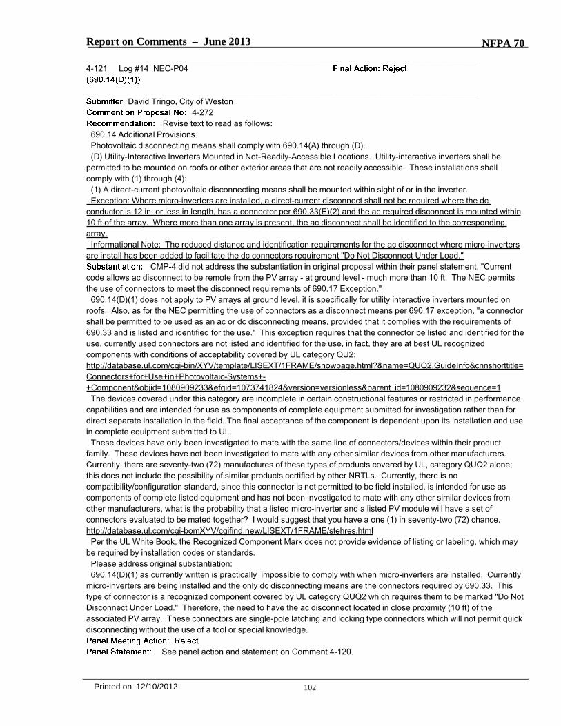
Report on Comments – June 2013 NFPA 70_______________________________________________________________________________________________4-121 Log #14 NEC-P04
_______________________________________________________________________________________________David Tringo, City of Weston
4-272Revise text to read as follows:
690.14 Additional Provisions.Photovoltaic disconnecting means shall comply with 690.14(A) through (D).(D) Utility-Interactive Inverters Mounted in Not-Readily-Accessible Locations. Utility-interactive inverters shall be
permitted to be mounted on roofs or other exterior areas that are not readily accessible. These installations shallcomply with (1) through (4):
(1) A direct-current photovoltaic disconnecting means shall be mounted within sight of or in the inverter.Exception: Where micro-inverters are installed, a direct-current disconnect shall not be required where the dc
conductor is 12 in. or less in length, has a connector per 690.33(E)(2) and the ac required disconnect is mounted within10 ft of the array. Where more than one array is present, the ac disconnect shall be identified to the correspondingarray.
Informational Note: The reduced distance and identification requirements for the ac disconnect where micro-invertersare install has been added to facilitate the dc connectors requirement "Do Not Disconnect Under Load."
CMP-4 did not address the substantiation in original proposal within their panel statement, "Currentcode allows ac disconnect to be remote from the PV array - at ground level - much more than 10 ft. The NEC permitsthe use of connectors to meet the disconnect requirements of 690.17 Exception."
690.14(D)(1) does not apply to PV arrays at ground level, it is specifically for utility interactive inverters mounted onroofs. Also, as for the NEC permitting the use of connectors as a disconnect means per 690.17 exception, "a connectorshall be permitted to be used as an ac or dc disconnecting means, provided that it complies with the requirements of690.33 and is listed and identified for the use." This exception requires that the connector be listed and identified for theuse, currently used connectors are not listed and identified for the use, in fact, they are at best UL recognizedcomponents with conditions of acceptability covered by UL category QU2:http://database.ul.com/cgi-bin/XYV/template/LISEXT/1FRAME/showpage.html?&name=QUQ2.GuideInfo&cnnshorttitle=Connectors+for+Use+in+Photovoltaic-Systems+-+Component&objid=1080909233&efgid=1073741824&version=versionless&parent_id=1080909232&sequence=1
The devices covered under this category are incomplete in certain constructional features or restricted in performancecapabilities and are intended for use as components of complete equipment submitted for investigation rather than fordirect separate installation in the field. The final acceptance of the component is dependent upon its installation and usein complete equipment submitted to UL.
These devices have only been investigated to mate with the same line of connectors/devices within their productfamily. These devices have not been investigated to mate with any other similar devices from other manufacturers.Currently, there are seventy-two (72) manufactures of these types of products covered by UL, category QUQ2 alone;this does not include the possibility of similar products certified by other NRTLs. Currently, there is nocompatibility/configuration standard, since this connector is not permitted to be field installed, is intended for use ascomponents of complete listed equipment and has not been investigated to mate with any other similar devices fromother manufacturers, what is the probability that a listed micro-inverter and a listed PV module will have a set ofconnectors evaluated to be mated together? I would suggest that you have a one (1) in seventy-two (72) chance.http://database.ul.com/cgi-bomXYV/cgifind.new/LISEXT/1FRAME/stehres.html
Per the UL White Book, the Recognized Component Mark does not provide evidence of listing or labeling, which maybe required by installation codes or standards.
Please address original substantiation:690.14(D)(1) as currently written is practically impossible to comply with when micro-inverters are installed. Currently
micro-inverters are being installed and the only dc disconnecting means are the connectors required by 690.33. Thistype of connector is a recognized component covered by UL category QUQ2 which requires them to be marked "Do NotDisconnect Under Load." Therefore, the need to have the ac disconnect located in close proximity (10 ft) of theassociated PV array. These connectors are single-pole latching and locking type connectors which will not permit quickdisconnecting without the use of a tool or special knowledge.
See panel action and statement on Comment 4-120.
102Printed on 12/10/2012
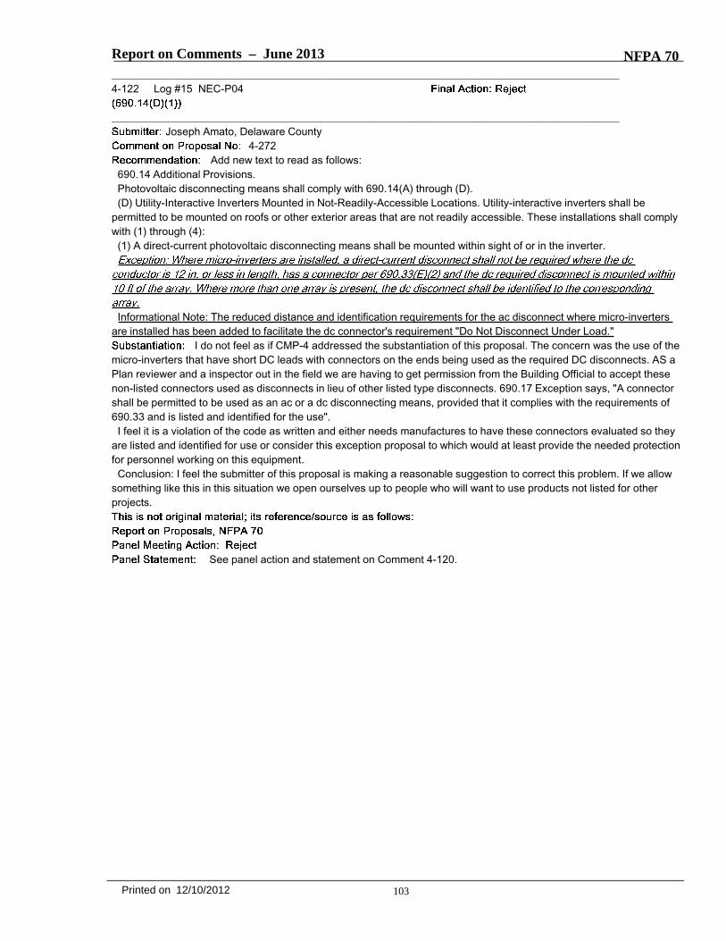
Report on Comments – June 2013 NFPA 70_______________________________________________________________________________________________4-122 Log #15 NEC-P04
_______________________________________________________________________________________________Joseph Amato, Delaware County
4-272Add new text to read as follows:
690.14 Additional Provisions.Photovoltaic disconnecting means shall comply with 690.14(A) through (D).(D) Utility-Interactive Inverters Mounted in Not-Readily-Accessible Locations. Utility-interactive inverters shall be
permitted to be mounted on roofs or other exterior areas that are not readily accessible. These installations shall complywith (1) through (4):
(1) A direct-current photovoltaic disconnecting means shall be mounted within sight of or in the inverter.
Informational Note: The reduced distance and identification requirements for the ac disconnect where micro-invertersare installed has been added to facilitate the dc connector's requirement "Do Not Disconnect Under Load."
I do not feel as if CMP-4 addressed the substantiation of this proposal. The concern was the use of themicro-inverters that have short DC leads with connectors on the ends being used as the required DC disconnects. AS aPlan reviewer and a inspector out in the field we are having to get permission from the Building Official to accept thesenon-listed connectors used as disconnects in lieu of other listed type disconnects. 690.17 Exception says, "A connectorshall be permitted to be used as an ac or a dc disconnecting means, provided that it complies with the requirements of690.33 and is listed and identified for the use".
I feel it is a violation of the code as written and either needs manufactures to have these connectors evaluated so theyare listed and identified for use or consider this exception proposal to which would at least provide the needed protectionfor personnel working on this equipment.
Conclusion: I feel the submitter of this proposal is making a reasonable suggestion to correct this problem. If we allowsomething like this in this situation we open ourselves up to people who will want to use products not listed for otherprojects.
See panel action and statement on Comment 4-120.
103Printed on 12/10/2012

Report on Comments – June 2013 NFPA 70_______________________________________________________________________________________________4-123 Log #1361 NEC-P04
_______________________________________________________________________________________________Ron B. Chilton, Rep. NC Code Clearing Committee.
4-272Revise Proposal by added text:
690.14. Additional Provisions.(D) Utility-Interactive Inverters Mounted in Not-Readily-Accessible Locations. Utility-interactive inverters shall bepermitted to be mounted on roofs or other exterior areas that are not readily accessible. these installations shall complywith (1) through(4).(1) A direct-current photovoltaic disconnecting means shall be mounted within sight of or in the inverter.Exception: Where micro-inverters are installed, a direct-current disconnect shall not be required where the dc conductoris 12 in. or less, has a connector identified in 690.33(E)(1) or (2), and the ac required disconnect is located within 10 ft. ifthe array. Where more than one array is present, the ac disconnect shall be marked with a label to identify which array itsupplies, in a manner acceptable to the Authority Having Jurisdiction.
Many DC connectors supplied with micro-inverters that utilize cords and plugs for installation are notload break rated and should have markings to indicate it is unsafe to attempt to use that connector to disconnect whenunder load conditions.
The panel action on Proposal 4-278a incorporated language suitable to submitter's concern by therevision of the last exception that added the words "for use with specific equipment".
_______________________________________________________________________________________________4-124 Log #70 NEC-P04
_______________________________________________________________________________________________Technical Correlating Committee on National Electrical Code®,
4-275It was the action of the Correlating Committee that this proposal be reconsidered and correlated
with the action on proposal 4-274a.This is a direction from the National Electrical Code Technical Correlating Committee in accordance
with 3.4.2 and 3.4.3 of the Regulations Governing Committee Projects.
The panel accepts the recommendation of the Correlating Committee. The panel action onProposal 4-274a is intended to address the concerns of the submitter of Proposal 4-275. The action on Proposal 4-275should have been "accept in principle" with statement "see panel action and statement on Proposal 4-274a".
104Printed on 12/10/2012

Report on Comments – June 2013 NFPA 70_______________________________________________________________________________________________4-125 Log #1168 NEC-P04
_______________________________________________________________________________________________Greg Pitz, Logos Solar
4-274aRevise text to read as follows:
690.15 Disconnection of Photovoltaic Equipment. Means shall be provided to disconnect equipment, such as inverters,batteries, and charge controllers, from all ungrounded conductors of all source sources. If the equipment is energizedfrom more than one source, the disconnecting means shall be grouped and identified. A single disconnecting means inaccordance with 690.17 shall be permitted for the combined ac output of one or more inverters or ac modules in aninteractive system.
(A) Utility Interactive Inverters Mounted in Not Readily Accessible Locations. Utility interactive inverters shall bepermitted to be mounted on roofs or other exterior areas that are not readily accessible and shall comply with (1)through (4):
(1) A direct‐current PV disconnecting means shall be mounted within sight of or in each inverter. A DC disconnectingmeans shall be installed within sight of the inverter to which it is electrically connected.
(2) An alternating‐current disconnecting means shall be mounted within sight of or in each inverter. An ACdisconnecting mean shall be installed within sight of the inverter(s) to which it is electrically connected.
(3) The alternating‐current AC output conductors from the inverter and an additional alternating‐current ACdisconnecting means for the inverter shall comply with 690.13(A).
(4) A plaque directory shall be installed in accordance with 705.10.(B) Equipment. Equipment such as PV source circuit isolating switches, overcurrent devices, dc–to–dc DC‐to‐DC
converters, and blocking diodes shall be permitted on the PV side of the PV disconnecting means.(C) DC Combiner Disconnects. The direct current (dc) output of dc combiners mounted installed on roofs of dwellings
or other buildings shall have a load break listed disconnecting means for the output located in the combiner or within 1.8m (6ft) of the combiner. The disconnecting means shall be permitted to be remotely controlled, but shall be manuallyoperable locally when control power is not available at all times.
A1) A DC disconnect is only connected to one inverter, it isnʹt necessarily mounted, and if it is ʺinʺ theinverter, it is visible, so the wording is unnecessary.
Addition of ʺPVʺ to text inconsistent. Why hasnʹt the descriptor been added to all other parts of this paragraph?Especially the very next line that is worded identically, except that DC is replaced with AC? Or similar descriptors in
any other portions of The Code that use DC generated by sources other than PV? This is the PV article of the code, soof course it is for PV.
A2) An AC disconnect can be connected to more than one inverter, it isn't necessarily mounted, and if it is "in" theinverter, it is visible, so the wording is unnecessary,
A 1 & A2) If multiple inverters, disconnects, combiners, are all in one area, don' t the disconnects mentioned here needto be related to the appropriate inverter(s)?
A3) And other locations - I like Mr Bower's consistency & format preferences,A4) The wording in 705,10 needs to be changed, as plagues aren't synonymous with directories, but directories may
be plaques,B) Consistency, None of the other lines have given a short top ic description at the start.C) Same consistency remark as immediately preceding. The "direct current" (spelled out for emphasis) isn't mounted
anywhere, so poor sentence construction, The disconnect might be integral to other equipment, so installed versusmounted, I'm sure the omission of "listing" was just an oversight as otherwise all disconnects will meet this criteria, If thedisconnect is integral to the combiner, that is within 1.8m, so unnecessary wording has been removed. Remotelycontrolled has been removed as this isn't a design manual.
Remote control is a technical requirement that improves safety and is a safety requirement thatneeds to remain. The changes to AC and DC (capitals) is not in accordance with the NEC Style Manual. Familiar termsare being changed which could cause confusion with the restructure of the main body of Article 690.
105Printed on 12/10/2012

Report on Comments – June 2013 NFPA 70_______________________________________________________________________________________________4-126 Log #1381 NEC-P04
_______________________________________________________________________________________________Chad Kennedy, Schneider Electric
4-274aRevise text to read as follows:
The direct current (dc) output of dc combiners mounted on roofs of dwellings or otherbuildings shall have a load break disconnecting means located in the combiner or within 1.8 m (6 ft) of the combiner andcomply with the requirements of 690.17. The disconnecting means shall be permitted to be remotely controlled, but shallbe manually operable locally when control power is not available.
Schneider Electric supports the enhancements to safety and fire service operations in the committeeaction on ROP 4-274a. However, the benefits of having dc combiner disconnects extend beyond just roof installationsand the requirements should be extended to apply in general.
This comment to include all systems is too restrictive for some systems. Load break disconnectingmeans on ground mounted PV system combiners may unnecessarily limit current practices.
_______________________________________________________________________________________________4-127 Log #71 NEC-P04
_______________________________________________________________________________________________Technical Correlating Committee on National Electrical Code®,
4-277The Correlating Committee directs that this proposal be correlated with the action on Proposal
4-254a that revised 690.13(D) for the maximum number of disconnecting means.This is a direction from the National Electrical Code Technical Correlating Committee in accordance
with 3.4.2 and 3.4.3 of the Regulations Governing Committee Projects.
Revise proposed 690.13(D) text as follows:(D) Maximum Number of Disconnects. The photovoltaic system disconnecting means shall consist of not more than six
switches or six circuit breakers mounted in a single enclosure, or in a group of a separate enclosures
The panel accepts the recommendation of the Correlating Committee. The section wasrenumbered from 690.15(C)(4) to 690.13(D) in Proposal 4-254a.
106Printed on 12/10/2012

Report on Comments – June 2013 NFPA 70_______________________________________________________________________________________________4-128 Log #72 NEC-P04
_______________________________________________________________________________________________Technical Correlating Committee on National Electrical Code®,
4-278aThe Correlating Committee directs that the panel clarify the action on this proposal to correlate
with the panel action taken on Proposal 4-264.The Correlating Committee further directs that this proposal be clarified by modifying the accepted text based on the
NEC Style Manual by removing the titles in the list of devices and changing the “(a) through (i)” to “(1) through (9).”In addition, the Correlating Committee directs that the panel reconsider the Informational Notes as related to the use of
permissive and mandatory text, in accordance with the NEC Style Manual.This is a direction from the National Electrical Code Technical Correlating Committee in accordance
with 3.4.2 and 3.4.3 of the Regulations Governing Committee Projects.
Revise proposed text of 690.17(A) as follows:(A) Manually Operable. The disconnecting means for ungrounded PV conductors shall consist of a manually operable
switch(es) or circuit breaker(s). The disconnecting means shall be permitted to be power operable with provisions formanual operation in the event of a power supply failure. The disconnecting means shall be one of the following listeddevices:
1) An industrial control switch marked for use in PV systems.2) A molded case circuit breaker marked for use in PV systems3) A molded case switch marked for use in PV systems.4) An enclosed switch marked for use in PV systems.5) An open type switch marked for use in PV systems.6) A dc rated molded case circuit breaker suitable for backfeed operation.7) A dc rated, molded case switch suitable for backfeed operation.8) A dc rated enclosed switch.9) A dc rated open type switch.10) A dc rated low voltage power circuit breaker.
The panel accepts the recommendation of the Correlating Committee. See panel statement onComment 4-118. The informational notes were not necessary and were removed. The panel action on Comment 4-129was incorporated into this comment.
107Printed on 12/10/2012

Report on Comments – June 2013 NFPA 70_______________________________________________________________________________________________4-129 Log #836 NEC-P04
_______________________________________________________________________________________________Thomas Hattert, SMA Solar Technology AG
4-278aRevise text to read as follows:
.(A) Manually Operable. The disconnecting means for ungrounded PV conductors shall consist of a manually operable
switch(es) or circuit breaker(s). The disconnecting means shall be permitted to be power operable with provisions formanual operation in the event of a power supply failure. The disconnecting means shall be one of the following devices:
(a) PV Industrial Control Switch. A listed industrial control switch marked for use in PV systems.(b) PV Molded Case Circuit Breaker. A listed molded case circuit breaker marked for use in PV systems(c) PV Molded Case Switch. A listed molded case switch marked for use in PV systems.(d) PV Enclosed Switch. A listed, enclosed switch marked for use in PV systems.(e) PV Open Type Circuit Breaker. A listed, open type circuit breaker marked for use in PV systems.(ef) PV Open Type Switch. A listed, open type switch marked for use in PV systems.(fg) Molded Case Circuit Breaker. A listed, dc rated molded case circuit breaker suitable for backfeed operation.(gh) Molded Case Switch. A listed, dc rated, molded case switch suitable for backfeed operation.(hi) Enclosed Switch. A listed, dc rated enclosed switch.(k) Open Type Circuit Breaker. A listed, dc rated open type circuit breaker.(ij) Open Type Switch. A listed, dc rated open type switch.Informational Note: Devices marked with “line” and “load” are not suitable for backfeed or reverse current.(B) Simultaneous Opening of Poles. The PV disconnecting means shall simultaneously disconnect all ungrounded
supply conductors that it controls from the building or structure wiring system.(C) Externally Operable and Indicating. The PV disconnecting means shall be externally operable without exposing the
operator to contact with live parts and indicate whether in the open or closed position(D) Disconnection of Grounded Conductor. A switch, circuit breaker, or other device shall not be installed in a
grounded conductor if operation of that switch, circuit breaker, or other device leaves the marked, grounded conductor inan ungrounded and energized state.
Exception No. 1: A switch or circuit breaker that is part of a ground-fault detection system required by 690.5, or that ispart of an arc-fault detection/interruption system required by 690.11, shall be permitted to open the grounded conductorwhen that switch or circuit breaker is automatically opened as a normal function of the device in responding to groundfaults.
Exception No. 2: A disconnecting switch shall be permitted in a grounded conductor if all of the following conditions aremet:
(1) The switch is used only for PV array maintenance.(2) The switch is accessible only by qualified persons.(3) The switch is rated for the maximum dc voltage and current that could be present during any operation, including
ground-fault conditions.Informational Note: The grounded conductor may have a bolted or terminal disconnecting means to allow maintenance
or troubleshooting by qualified personnel.(F) Interrupting Rating. The building or structure disconnecting means shall have an interrupting rating sufficient for the
maximum circuit voltage and current that is available at the line terminals of the equipment. Where all terminals of thedisconnecting means may be energized in the open position, a warning sign shall be mounted on or adjacent to thedisconnecting means. The sign shall be clearly legible and have the following words or equivalent:
WARNINGELECTRIC SHOCK HAZARD.DO NOT TOUCH TERMINALS.TERMINALS ON BOTH THE LINE AND LOAD SIDESMAY BE ENERGIZED IN THE OPEN POSITION.Exception: A connector shall be permitted to be used as an ac or a dc disconnecting means, provided that it complies
with the requirements of 690.33 and is listed and identified for use with specific equipment.The original proposal would exclude open type circuit breakers that are covered by UL1066. For AC
applications these type of breakers are commonly used as disconnecting means. Right now UL 1066 also permits themto have a DC rating up to 300V DC.
108Printed on 12/10/2012
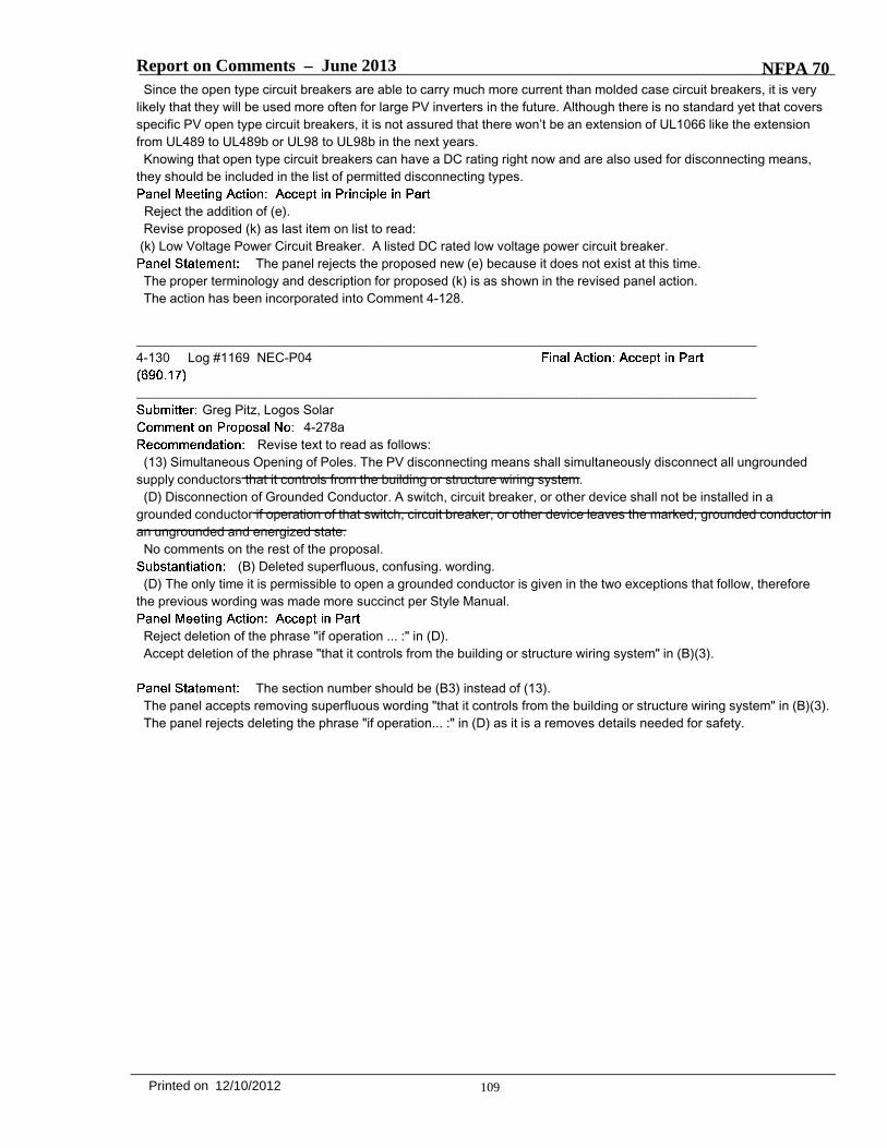
Report on Comments – June 2013 NFPA 70Since the open type circuit breakers are able to carry much more current than molded case circuit breakers, it is very
likely that they will be used more often for large PV inverters in the future. Although there is no standard yet that coversspecific PV open type circuit breakers, it is not assured that there won’t be an extension of UL1066 like the extensionfrom UL489 to UL489b or UL98 to UL98b in the next years.
Knowing that open type circuit breakers can have a DC rating right now and are also used for disconnecting means,they should be included in the list of permitted disconnecting types.
Reject the addition of (e).Revise proposed (k) as last item on list to read:
(k) Low Voltage Power Circuit Breaker. A listed DC rated low voltage power circuit breaker.The panel rejects the proposed new (e) because it does not exist at this time.
The proper terminology and description for proposed (k) is as shown in the revised panel action.The action has been incorporated into Comment 4-128.
_______________________________________________________________________________________________4-130 Log #1169 NEC-P04
_______________________________________________________________________________________________Greg Pitz, Logos Solar
4-278aRevise text to read as follows:
(13) Simultaneous Opening of Poles. The PV disconnecting means shall simultaneously disconnect all ungroundedsupply conductors that it controls from the building or structure wiring system.
(D) Disconnection of Grounded Conductor. A switch, circuit breaker, or other device shall not be installed in agrounded conductor if operation of that switch, circuit breaker, or other device leaves the marked, grounded conductor inan ungrounded and energized state.
No comments on the rest of the proposal.(B) Deleted superfluous, confusing. wording.
(D) The only time it is permissible to open a grounded conductor is given in the two exceptions that follow, thereforethe previous wording was made more succinct per Style Manual.
Reject deletion of the phrase "if operation ... :" in (D).Accept deletion of the phrase "that it controls from the building or structure wiring system" in (B)(3).
The section number should be (B3) instead of (13).The panel accepts removing superfluous wording "that it controls from the building or structure wiring system" in (B)(3).The panel rejects deleting the phrase "if operation... :" in (D) as it is a removes details needed for safety.
109Printed on 12/10/2012
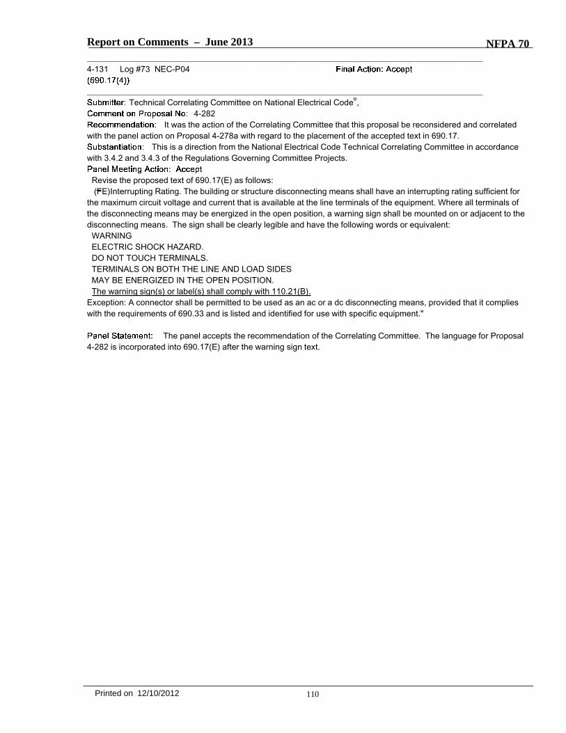
Report on Comments – June 2013 NFPA 70_______________________________________________________________________________________________4-131 Log #73 NEC-P04
_______________________________________________________________________________________________Technical Correlating Committee on National Electrical Code®,
4-282It was the action of the Correlating Committee that this proposal be reconsidered and correlated
with the panel action on Proposal 4-278a with regard to the placement of the accepted text in 690.17.This is a direction from the National Electrical Code Technical Correlating Committee in accordance
with 3.4.2 and 3.4.3 of the Regulations Governing Committee Projects.
Revise the proposed text of 690.17(E) as follows:(FE)Interrupting Rating. The building or structure disconnecting means shall have an interrupting rating sufficient for
the maximum circuit voltage and current that is available at the line terminals of the equipment. Where all terminals ofthe disconnecting means may be energized in the open position, a warning sign shall be mounted on or adjacent to thedisconnecting means. The sign shall be clearly legible and have the following words or equivalent:
WARNINGELECTRIC SHOCK HAZARD.DO NOT TOUCH TERMINALS.TERMINALS ON BOTH THE LINE AND LOAD SIDESMAY BE ENERGIZED IN THE OPEN POSITION.The warning sign(s) or label(s) shall comply with 110.21(B).
Exception: A connector shall be permitted to be used as an ac or a dc disconnecting means, provided that it complieswith the requirements of 690.33 and is listed and identified for use with specific equipment."
The panel accepts the recommendation of the Correlating Committee. The language for Proposal4-282 is incorporated into 690.17(E) after the warning sign text.
110Printed on 12/10/2012

Report on Comments – June 2013 NFPA 70_______________________________________________________________________________________________4-132 Log #74 NEC-P04
_______________________________________________________________________________________________Technical Correlating Committee on National Electrical Code®,
4-284aIt was the action of the Correlating Committee that the panel action on this proposal be
reconsidered and the text be rewritten to use letters rather than numbers for each list item in the sub-list of 690.31(G)(3)in compliance with 2.1.5.3, Level 3 of the NEC Style Manual.
The Correlating Committee directs that the panel change the word “when” to “where” in the first sentence in thisproposal and in 690.31(D) since this is not a condition of time.
The Correlating Committee further directs the panel to address the permissive use of the word "may" in theInformational Notes in accordance with the NEC Style Manual.
This is a direction from the National Electrical Code Technical Correlating Committee in accordancewith 3.4.2 and 3.4.3 of the Regulations Governing Committee Projects.
Informational Note: Photovoltaic modules operate at elevated temperatures when exposed to high ambienttemperatures and to bright sunlight. These temperatures routinely exceed 70°C (158°F) in many locations. Moduleinterconnection conductors are available with insulation rated for wet locations and a temperature rating of 90°C (194°F)or greater.
Informational Note: Photovoltaic (PV) wire [also photovoltaic (PV) cable] has a nonstandard outer diameter. Conduit fillis calculated using Table 1 of Chapter 9.
(D) Multi-conductor Cable. Multi-conductor cable type TC-ER or USE-2 shall be permitted in outdoor locations in PVinverter output circuits where used with utility-interactive inverters mounted in not-readily-accessible locations. The cableshall be secured at intervals not exceeding 1.8m (6 ft.). Equipment grounding for the utilization equipment shall beprovided by an equipment grounding conductor within the cable.
(G) Direct-Current Photovoltaic Source and DC Output Circuits On or Inside a Building. Where dc PV source or dc PVoutput circuits from a building-integrated or other PV systems are run inside a building or structure, they shall becontained in metal raceways, Type MC metal-clad cable that complies with 250.118(10), or metal enclosures from thepoint of penetration of the surface of the building or structure to the first readily accessible disconnecting means. Thedisconnecting means shall comply with 690.13(B), (C), and 690.15(A), (B). The wiring methods shall comply with theadditional installation requirements in (1) through (4)
(a) Embedded in Building Surfaces. Where circuits are embedded in built-up, laminate, or membrane roofing materialsin roof areas not covered by PV modules and associated equipment, the location of circuits shall be clearly markedusing a marking protocol that is approved as being suitable for continuous exposure to sunlight and weather.
(b) Flexible Wiring Methods. Where flexible metal conduit (FMC) smaller than metric designator 21 (trade size 3/4) orType MC cable smaller than 25 mm (1 in.) in diameter containing PV power circuit conductors is installed across ceilingsor floor joists, the raceway or cable shall be protected by substantial guard strips that are at least as high as the racewayor cable. Where run exposed, other than within 1.8 m (6 ft) of their connection to equipment, these wiring methods shallclosely follow the building surface or be protected from physical damage by an approved means.
(c) Marking or Labeling Required. The following wiring methods and enclosures that contain PV power sourceconductors shall be marked with the wording Warning: Photovoltaic Power Source” by means of permanently affixedlabels or other approved permanent marking:
(1) Exposed raceways, cable trays, and other wiring methods(2) Covers or enclosures of pull boxes and junction boxes(3) Conduit bodies in which any of the available conduit openings are unused(4) Marking and Labeling Methods and Locations. The labels or markings shall be visible after installation. The labels
shall be reflective and shall have all letters capitalized with a minimum height of 9.5 mm (3/8 inch) white on redbackground. PV power circuit labels shall appear on every section of the wiring system that is separated by enclosures,walls, partitions, ceilings, or floors. Spacing between labels or markings, or between a label and a marking, shall not bemore than 3 m (10 ft). Labels required by this section shall be suitable for the environment where they are installed.
111Printed on 12/10/2012

Report on Comments – June 2013 NFPA 70The panel accepts the recommendation of the Correlating Committee. In part (D) the word “when”
was change to “where”. In part (G) the section numbers were changed to letters. The word “may” was removed fromthe (A) informational note and changed to "is" in the (C) informational note.
_______________________________________________________________________________________________4-133 Log #1170 NEC-P04
_______________________________________________________________________________________________Greg Pitz, Logos Solar
4-284aRevise text to read as follows:
(4) Marking and Labeling Methods and Locations. The labels or markings shall be visible after installation. The labelsshall be reflective and shall have all letters capitalized with a minimum height of 9.5 mm (3/8 inch) white black on redorange background. PV power circuit labels shall appear on every section of the wiring system that is separated byenclosures, walls, partitions, ceilings, or floors. Spacing between labels or markings, or between a label and a marking,shall not be more than 3 m (10 ft). Labels required by this section shall be suitable for the environment where they areinstalled.
No comments on the rest of the proposal.This Comment is to make the Proposal consistent with United States standards (ANSI standards
Z35.1‐1968, Z53.1‐1967, Z535.2, Z535.1‐6), international standards (ISO 3864 & 7010:2011), and to make it legal inthe USA (OSHA federal laws, 29 CFR 1910.144 & 1910.145).
ANSI is the standards organization in the USA. The ANSI committee on Safety Signs and Colors has been keepingsignage in the USA in agreement with the rest of the world since 1998. OSHA regulations are usually closely linked toANSI standards. The IFC recently adopted the standard mentioned in the proposal, which, unfortunately, was donebefore checking other existing standards & laws. Attempts are being made to change said IFC standard so that it is inagreement with the standards & federal laws quoted above.
OHSA does not recognize the use of the word ʺlabelʺ, formally defining all means of notification as ʺsignsʺ. ANSI &OSHA explicitly tell us that warning signs are to have black letters & symbols on orange background.
References, including OSHA interpretations of their standards (laws), available upon request.This comment is also to coordinate with accepted proposal 1‐114 Log #847, article 110.21(A) and (B)), markings.
The panel rejects the black on orange OSHA color scheme in favor of the firefighters required colorscheme.
112Printed on 12/10/2012

Report on Comments – June 2013 NFPA 70_______________________________________________________________________________________________4-134 Log #1074 NEC-P04
_______________________________________________________________________________________________John C. Wiles, Southwest Technology Development Institute, New Mexico State University
4-284aDelete the inserted text and retain the 2011 language.
PV source circuits and PV output circuits shall not be contained in the same raceway,cable tray, cable, outlet box, junction box, or similar fitting as conductors, feeders, branch circuits of other non-PVsystems, or inverter output circuits unless the conductors of the different systems are separated by a partition. PVsystem conductors shall be identified and grouped as required by 690.31(B)(1) through (4). The means of identificationshall be permitted by separate color coding, marking tape, tagging, or other approved means.
The panel was in error in accepting the proposal 4-194. The original language of 690.31(B) providesprotections specific to the unique nature of PV sources by limiting conductors, feeders or branch circuits ofsystems within the same raceway, cable tray, cable, outlet box, junction box, or similar fitting as PV source and outputcircuits, because a typical person servicing a non-PV circuit expects it to be deenergized after opening all OCPD at theservice panel, whereas PV source and output circuits may remain energized whenever the sun is shining. This proposalattempts to layer additional theoretical protections against the potential risk to equipment due to a double fault condition.However, the proposed inclusion of “or inverter output circuits” is contrary to the specific nature of solar inverters, placesan unrealistic burden on installers and inspectors, and does not provide the safety the submitter intends. 300.3(C)(1) allows conductors of ac and dc circuits to occupy the same equipment wiring enclosure, cable, or raceway,provided all conductors have an insulation rating equal to at least the maximum circuit voltage applied to any conductorwithin the enclosure, cable, or raceway. Inverters have, by definition, both AC and DC inputs and outputs, andmulti-mode inverters may have multiple inputs and outputs. Many manufacturers have developed balance of systemcomponents with both AC and DC circuit routing and OCPD to accommodate these multiple inputs and outputs, andenable safe and practical installation of listed inverters. This proposal would call into question whether those productscould be installed as designed and intended. Adequate provisions currently exist to ensure safety in photovoltaicsystems – Chapter 3 provides the wiring methods required for safety, 690.15, 16 and 17 require that devices beidentified if energized from multiple sources, and 690.4(E) requires service on these systems to be performed only byqualified persons.The 2011 NEC handbook includes commentary which clarifies the intent of this section by specifically stating this “doesnot permit the alternating-current branch-circuit conductors that supply an exterior luminaire installed near aroof-mounted PV array to share the same raceway or cable with the conductors of PV source circuits or PV outputcircuits. Conductors directly related to a specific PV system, such as those in dc and ac output power circuits, may becontained in the same raceway as PV source and output conductors, providing they meet the requirements of690.4(B)(1) through (B)(4) and 300.3(C).
The submitter is correct that there are allowances in Chapter 3 of the NEC for combinations ofconductors in cables or raceways provided they all have appropriate insulation levels and are of the proper type circuitclassification. That being said it is not commonplace for this to happen and even if it does the systems do not have thesame characteristics as other electrical systems and thus have their own Article. Bringing these circuits together withinlisted equipment is not an issue as the equipment has been evaluated for that, the issue is outside of that equipment.Failures in conductor insulation that impose AC voltages on DC circuits of PV systems would most likely not facilitateover-current devices and could cause catastrophic damage to the circuitry within PV modules leading to module failureand potentially fires. The issue is a matter of workmanlike installations by qualified persons that have the knowledge andability to route electrical installations and maintain separation all the way from the source to the listed equipment.
113Printed on 12/10/2012

Report on Comments – June 2013 NFPA 70_______________________________________________________________________________________________4-135 Log #1075 NEC-P04
_______________________________________________________________________________________________John C. Wiles, Southwest Technology Development Institute, New Mexico State University
4-290Proposed Text (Modified from Proposal 4-290):
PV source circuits and PV output circuits using single-conductor cable listed and labeled as PV wire of all sizes with orwithout a CT marking/rating shall be permitted in cable trays provided the cables are secured and supported inaccordance with 338.10(B)(4)(b) and are not on or penetrating a building. PV systems using cable trays on buildingsmust comply with 392.
We want to thank the CMP for considering Proposal 4-290 and request that the proposal bereconsidered. The CMP was concerned about Cable Trays being limited to Industrial Establishments in its PanelStatement. As Jim Rogers pointed out in his comment, this was a misunderstanding. The permissibility of Cable Traysoutside of Industrial Establishments is directly addressed in 392.10, which states “… Cable tray installations shall not belimited to industrial establishments …” Nonetheless, after discussing the proposal with representatives of Code MakingPanels 7 and 8 as suggested by Jim Rogers, we have modified the proposed modification to streamline the revisionrequest and better align the language with the NEC style and language requirements.In an attempt to reduce the impact of the requested revision, we have modified the proposed language to reduce itsscope to PV Wire only. Also, we have focused the language on permitting the use of these cables in ground mountsystems only (systems not on or penetrating a building) and have eliminated the cable tray fill and conductor ampacityguidelines. We have also made it very clear that the cables must continue to meet the support requirements that arecurrently required in 33810(B)(4)(b). Given that cable trays provide a superior protection and support for the PV Sourcecircuits relative to what is already required in 690, we ask that the CMP reevaluate this proposal and adopt thestreamlined language proposed in this comment.As additional background information, it became clear during conversations with CMP 4 representatives that theproblem being addressed by this revision was not well understood. Based on the Working Group’s experience withdesigning ground mount PV systems, AHJ’s have difficultly interpreting the NEC requirements for installing singleconductor PV Wire cables smaller than #1/0 AWG in cable trays. The difficulty is that section 392 does NOT addressinstallation of single conductor cables smaller than #1/0AWG in cable trays, suggesting that it is not permitted. Similarly,the TC ratings in the standards are not available for single conductor cables smaller than #1/0AWG. Using this line ofreasoning, AHJs sometimes reject installing these cables in cable trays. On the other hand, the NEC permits the use ofUSE-2 or PV wire in PV systems (exposed, outdoor environments 690.31(B)) because these cables are designed foroutdoor use. Furthermore, the support requirements for USE cables in exterior locations is only every 4.5 feet asdefined in 334.30, which is referenced by 338.10(B)(4)(b). All cable tray designs are superior to both of these conditionsin that they provide protection from physical damage for these cables and the maximum support spans are much lessthan 4.5 feet. As a result, AHJs often approve the use of cable trays in this application. As a PV System design, thisuncertainty and contradiction in the NEC adds unnecessary complexity to the design process. Thus, we ask that theCMP revise 690 to resolve this contradiction.From an engineering standpoint, we learned from conversations with UL representatives that the #1/0 AWG singleconductor restriction was imposed long before our application was envisioned. Additionally, the TC rating deals withspread of flame prevention, which is required for applications inside of buildings. Since the PV Wire standard alreadyincludes a flame resistance test, the TC rating adds no value for ground mount PV systems. The TC spread of flametest was designed to prevent cable trays that pass through firewalls from allowing a fire to breech the firewall. Clearly,this requirement is not needed for ground mount PV systems. By eliminating the TC requirement for ground mountedPV systems, it would allow PV Wire cables smaller than #1/0 AWG, which are outside of the scope of the TC standard,to be installed in cable trays. Lastly, ladder style cable trays have rung spacings ranging from 6” to 18”, with spacingsbetween 6” and 12” typically being used for PV systems. Thus, the support provided to the cables in a cable tray isvastly superior to the requirements stipulated in 334.30.
See panel action and statement on Comment 4-136, which addresses the concerns of thesubmitter.
114Printed on 12/10/2012

Report on Comments – June 2013 NFPA 70_______________________________________________________________________________________________4-136 Log #1511 NEC-P04
_______________________________________________________________________________________________Mark Albers, SunPower Corp.
4-290
PV source circuits and PV output circuits using single-conductor cable listed and labeled as PV wire of all sizes with orwithout a Cable Tray marking/rating shall be permitted in cable trays provided the cables are supported at intervals notto exceed 12 in and the cable trays are not on or penetrating a building. PV systems using cable trays on buildings mustcomply with 392.
I support the comment submitted by the PV Industry Forum. However, since this comment wassubmitted, a concern was raised that the requirement should be more self-sufficient and not reference Article 338because it is defining a requirement unique to PV Systems. Consequently, I replaced the reference to 338.10(B)(4)(b)with arequirement that the cables be supported every 12”. This maximum span is significantly smaller than the 4.5’ required in338. It is also the largest support span typically used for cable trays currently designed into ground mounted PVsystems. Since the insulation used in PV Wire cables is more robust than USE cables, it is very capable of safelyspanning 12”.I have also replaced the reference to CT with Cable Tray as the markings used for cables with the optional designationfor use in Cable Trays have many different forms, CT being one of them. The term Cable Tray marking/rating willencompass all of the optional designations that might otherwise be required. As additional supporting documentation,the attached document prepared by Christel Hunter, Engineering Manager at General Cable, summarizes the additionaltesting required for the optional Cable Tray designations. Clearly, the designation in these two standards only requiresthe addition of a vertical tray flame test. As stated in the PV Industry Forum Comment Substantiation, this capability isintended to prevent the spread of fire in an indoor application and was not intended to be applied to an outdoorapplication. Thus, the Cable Tray rating is not necessary for a ground mounted PV system.
The panel rejects the proposed wording "and the cable trays are not on or penetrating a building. PV systems usingcable trays on buildings must comply with 392."
Revise 690.31(C) to read as follows:(C) Single-Conductor Cable.(1) Single-conductor cable type USE-2, and single-conductor cable listed and labeled as photovoltaic (PV) wire shall
be permitted in exposed outdoor locations in PV source circuits for PV module interconnections within the PV array.Exception: Raceways shall be used when required by 690.31(A).(2) PV source circuits and PV output circuits using single-conductor cable listed and labeled as Photovoltaic (PV) wire
of all sizes with or without a Cable Tray marking/rating shall be permitted in cable trays installed in outdoor locationsprovided the cables are supported at intervals not to exceed 30cm (12 in.) and secured at intervals not to exceed 1.4m(4.5’).
Informational Note: Photovoltaic (PV) wire [also photovoltaic (PV) cable] has a nonstandard outer diameter. Conduit fillmay be calculated using Table 1 of Chapter 9.
The panel rejects the proposed wording "and the cable trays are not on or penetrating a building.PV systems using cable trays on buildings must comply with 392." Outdoor locations is used for clarity and thereference to Article 392 is redundant. The panel acknowledges that PV circuits are allowed in cable trays inside abuilding but they must meet other applicable code requirements.
The secure interval meets the requirement of 338.10(B)(4)(b) and the support interval exceeds the requirement of338.10(B)(4)(b).
115Printed on 12/10/2012

Report on Comments – June 2013 NFPA 70_______________________________________________________________________________________________4-137 Log #1171 NEC-P04
_______________________________________________________________________________________________Greg Pitz, Logos Solar
4-296Revise text to read as follows:
Marking or Labeling Required. The following wiring methods and enclosures that contain PV power source conductorsshall be marked with the wording “WARNING: PHOTOVOLTAIC POWER SOURCE” by means of permanently affixedlabels or other approved permanent marking:
(1) Exposed raceways, cable trays, and other wiring methods(2) Covers or enclosures of pull boxes and junction boxes(3) Conduit bodies in which any of the available conduit openings are unused(4) Marking and Labeling Methods and Locations. The labels or markings shall be visible after installation. The labels
shall be reflective, shall have all letters capitalized with a minimum height of 9.5 mm (3/8 inch) white black on red orangebackground. Photovoltaic power circuit labels shall appear on every section of the wiring system that is separated byenclosures, walls, partitions, ceilings, or floors. Spacing between labels or markings, or between a label and a marking,shall not be more than 3 m (10 ft). Labels required by this section shall be suitable for the environment where in whichthey are installed.
This Comment is to make the Proposal consistent with United States standards (ANSI standardsZ35.1‐1968, Z53.1‐1967, Z535.2, Z535.1‐6), international standards (ISO 3864 & 7010:2011), and to make it legal inthe USA (OSHA federal laws, 29 CFR 1910.144 & 1910.145).
ANSI is the standards organization in the USA. The ANSI committee on Safety Signs and Colors has been keepingsignage in the USA in agreement with the rest of the world since 1998. OSHA regulations are usually closely linked toANSI standards. The IFC recently adopted the standard mentioned in the proposal, which, unfortunately, was donebefore checking other existing standards & laws. Attempts are being made to change said IFC standard so that it is inagreement with the standards & federal laws quoted above.OHSA does not recognize the use of the word ʺlabelʺ, formally defining all means of notification as ʺsignsʺ. ANSI &OSHA explicitly tell us that warning signs are to have black letters & symbols on orange background.
References, including OSHA interpretations of their standards, available upon request.ʺWhereʺ vs ʺin whichʺ: The former doesnʹt precisely define which environment. Indoor? Outdoor? The site
environment?This comment is also to coordinate with accepted proposal 1‐114 Log #847, article 110.21(A) and (B)), markings.
See panel action and statement on Comment 4-133.
116Printed on 12/10/2012
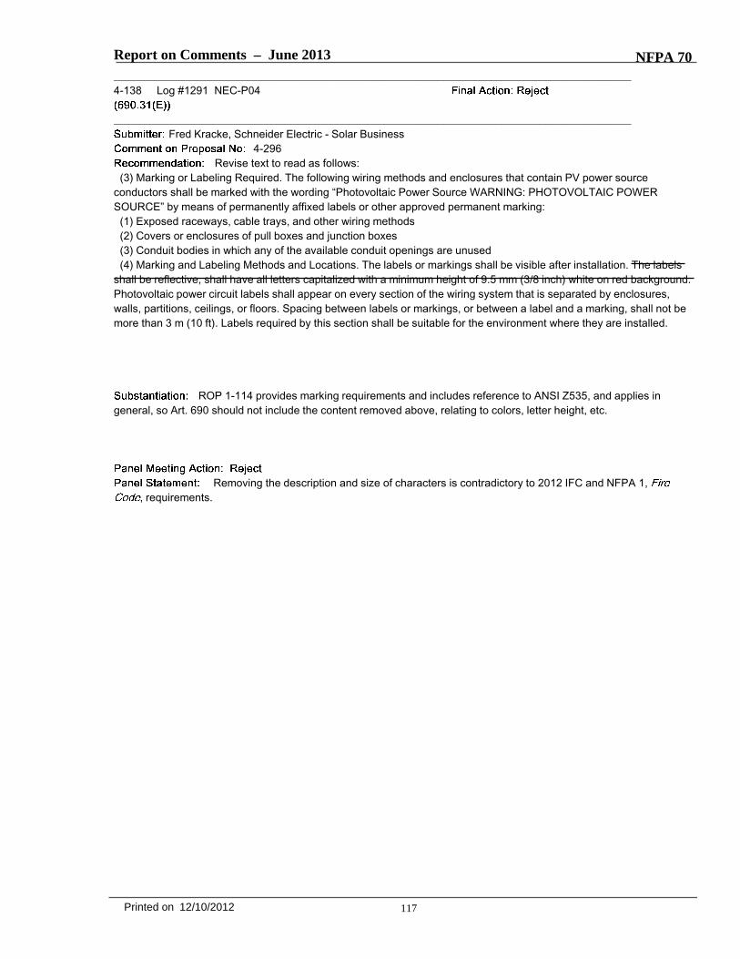
Report on Comments – June 2013 NFPA 70_______________________________________________________________________________________________4-138 Log #1291 NEC-P04
_______________________________________________________________________________________________Fred Kracke, Schneider Electric - Solar Business
4-296Revise text to read as follows:
(3) Marking or Labeling Required. The following wiring methods and enclosures that contain PV power sourceconductors shall be marked with the wording “Photovoltaic Power Source WARNING: PHOTOVOLTAIC POWERSOURCE” by means of permanently affixed labels or other approved permanent marking:
(1) Exposed raceways, cable trays, and other wiring methods(2) Covers or enclosures of pull boxes and junction boxes(3) Conduit bodies in which any of the available conduit openings are unused(4) Marking and Labeling Methods and Locations. The labels or markings shall be visible after installation. The labels
shall be reflective, shall have all letters capitalized with a minimum height of 9.5 mm (3/8 inch) white on red background.Photovoltaic power circuit labels shall appear on every section of the wiring system that is separated by enclosures,walls, partitions, ceilings, or floors. Spacing between labels or markings, or between a label and a marking, shall not bemore than 3 m (10 ft). Labels required by this section shall be suitable for the environment where they are installed.
ROP 1-114 provides marking requirements and includes reference to ANSI Z535, and applies ingeneral, so Art. 690 should not include the content removed above, relating to colors, letter height, etc.
Removing the description and size of characters is contradictory to 2012 IFC and NFPA 1,, requirements.
117Printed on 12/10/2012
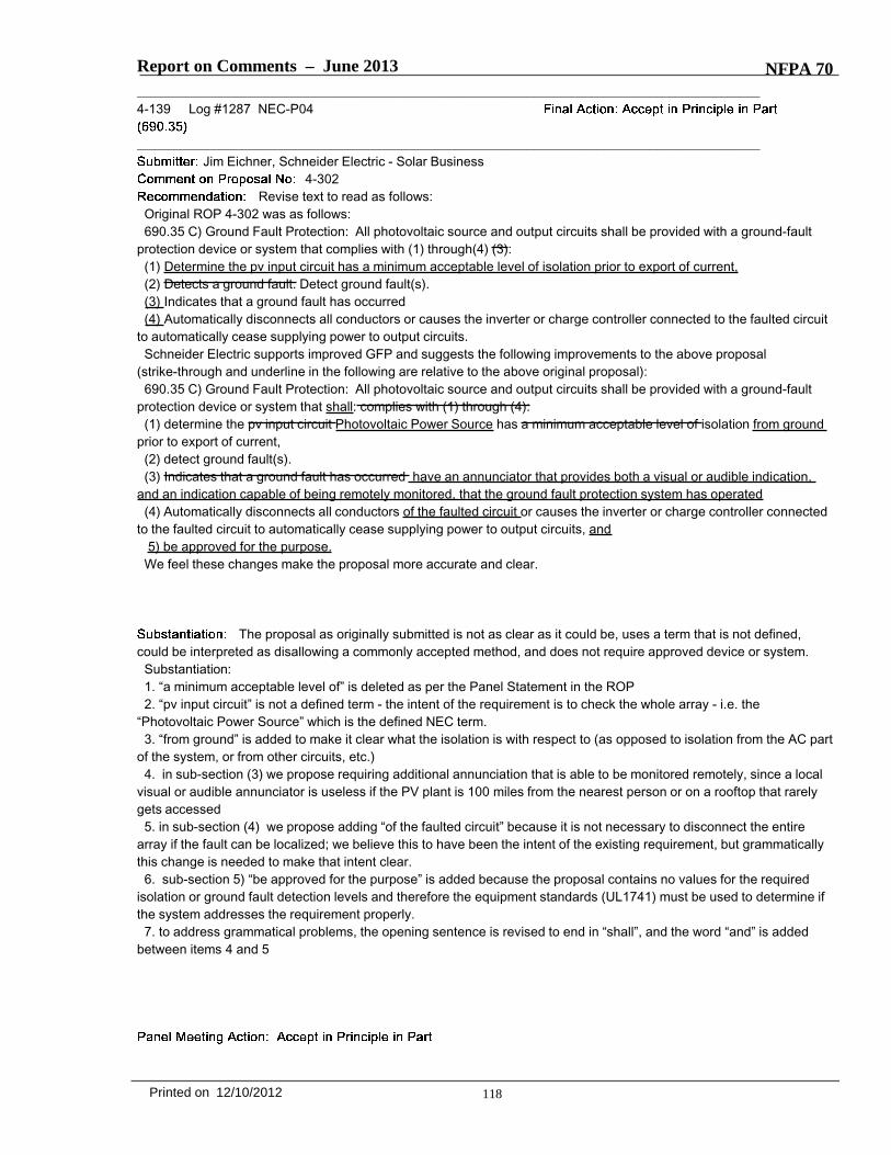
Report on Comments – June 2013 NFPA 70_______________________________________________________________________________________________4-139 Log #1287 NEC-P04
_______________________________________________________________________________________________Jim Eichner, Schneider Electric - Solar Business
4-302Revise text to read as follows:
Original ROP 4-302 was as follows:690.35 C) Ground Fault Protection: All photovoltaic source and output circuits shall be provided with a ground-fault
protection device or system that complies with (1) through(4) (3):(1) Determine the pv input circuit has a minimum acceptable level of isolation prior to export of current,(2) Detects a ground fault. Detect ground fault(s).(3) Indicates that a ground fault has occurred(4) Automatically disconnects all conductors or causes the inverter or charge controller connected to the faulted circuit
to automatically cease supplying power to output circuits.Schneider Electric supports improved GFP and suggests the following improvements to the above proposal
(strike-through and underline in the following are relative to the above original proposal):690.35 C) Ground Fault Protection: All photovoltaic source and output circuits shall be provided with a ground-fault
protection device or system that shall: complies with (1) through (4):(1) determine the pv input circuit Photovoltaic Power Source has a minimum acceptable level of isolation from ground
prior to export of current,(2) detect ground fault(s).(3) Indicates that a ground fault has occurred have an annunciator that provides both a visual or audible indication,
and an indication capable of being remotely monitored, that the ground fault protection system has operated(4) Automatically disconnects all conductors of the faulted circuit or causes the inverter or charge controller connected
to the faulted circuit to automatically cease supplying power to output circuits, and5) be approved for the purpose.
We feel these changes make the proposal more accurate and clear.
The proposal as originally submitted is not as clear as it could be, uses a term that is not defined,could be interpreted as disallowing a commonly accepted method, and does not require approved device or system.
Substantiation:1. “a minimum acceptable level of” is deleted as per the Panel Statement in the ROP2. “pv input circuit” is not a defined term - the intent of the requirement is to check the whole array - i.e. the
“Photovoltaic Power Source” which is the defined NEC term.3. “from ground” is added to make it clear what the isolation is with respect to (as opposed to isolation from the AC part
of the system, or from other circuits, etc.)4. in sub-section (3) we propose requiring additional annunciation that is able to be monitored remotely, since a local
visual or audible annunciator is useless if the PV plant is 100 miles from the nearest person or on a rooftop that rarelygets accessed
5. in sub-section (4) we propose adding “of the faulted circuit” because it is not necessary to disconnect the entirearray if the fault can be localized; we believe this to have been the intent of the existing requirement, but grammaticallythis change is needed to make that intent clear.
6. sub-section 5) “be approved for the purpose” is added because the proposal contains no values for the requiredisolation or ground fault detection levels and therefore the equipment standards (UL1741) must be used to determine ifthe system addresses the requirement properly.
7. to address grammatical problems, the opening sentence is revised to end in “shall”, and the word “and” is addedbetween items 4 and 5
118Printed on 12/10/2012

Report on Comments – June 2013 NFPA 70
See panel action on Comment 4-141.The panel rejects the changes in 3). Specific product requirements and the remote monitoring and annunciator belong
in the product standard.The correct section reference is 690.35(C).
_______________________________________________________________________________________________4-140 Log #1076 NEC-P04
_______________________________________________________________________________________________John C. Wiles, Southwest Technology Development Institute, New Mexico State University
4-302Revise the text from proposal 4-302 as follows:
All photovoltaic source and output circuits shall be provided with a ground-fault protectiondevice or system that complies with (1) through (4):(1) Determine the pv input circuit has isolation prior to export of current(1) (2) Detects ground fault(s) in the PV array dc current carrying conductors and components(2) (3) Indicates that a ground fault has occurred(3) (4) Automatically disconnects all conductors or causes the inverter or charge controller connected to the faultedcircuit to automatically cease supplying power to output circuits, and(4) Be listed for providing PV ground fault protection
Inadequate ground fault protection has caused several fires in PV systems over the last half decade.Clearly ground fault protection (GFP) capabilities need to be improved in new PV systems. As result, we applaud andsupport the Code Making Panel in addressing this important issue. However, the newly proposed 2014 language doesraise very serious concerns. It requires the use of insulation resistance measurements in all systems at some unknownfrequency. The statement of “… prior to the export of current” is not enforceable because it is unclear how frequentlythis test would have to be performed. It could be interpreted to be: 1) before the system is turned on for the first time; 2)every night; or 3) every time the inverter starts up. Furthermore, the new language could be interpreted to mean that thesystem needs to test for a ground fault only at this undefined time, leaving the system free to operate with a ground faultin between tests.Additionally, insulation resistance measurements are not universally effective and will not be the best GFP for all PVsystem designs. Moreover, as new technologies come to market, GFP methods superior to insulation resistancemeasurements may emerge. We want the 2014 NEC to address the inadequacies of present GFP once and for all andnot legislate the use of a specific solution. Additionally, we propose to add a requirement that the GFP be listed forprotection PV systems. This will allow the inspector to rely upon the listing to verify the functionality of this extremelyimportant protection system, which will improve the enforceability of the GFP requirements. For these reasons, werequest that you adapt 690.35(C) to read as modified above. This will stimulate UL 1741 to be updated to reflect theneeds for improved GFP in PV systems and to ensure that the new functional requirements are met without requiring aspecific implementation/solution.
See panel action on Comment 4-141 which addresses the concerns of the submitter.
119Printed on 12/10/2012
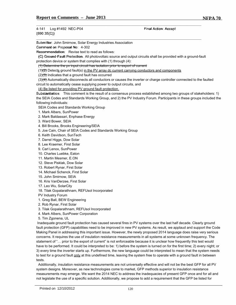
Report on Comments – June 2013 NFPA 70_______________________________________________________________________________________________4-141 Log #1492 NEC-P04
_______________________________________________________________________________________________John Smirnow, Solar Energy Industries Association
4-302Revise text to read as follows:
All photovoltaic source and output circuits shall be provided with a ground-faultprotection device or system that complies with (1) through (4):
(1) Determine the pv input circuit has isolation prior to export of current(1)(2) Detects ground fault(s) in the PV array dc current carrying conductors and components(2)(3) Indicates that a ground fault has occurred(3)(4) Automatically disconnects all conductors or causes the inverter or charge controller connected to the faulted
circuit to automatically cease supplying power to output circuits, and(4) Be listed for providing PV ground fault protection
This comment is the result of a consensus process established among two groups of stakeholders: 1)the SEIA Codes and Standards Working Group, and 2) the PV Industry Forum. Participants in these groups included thefollowing individuals:
SEIA Codes and Standards Working Group1. Mark Albers, SunPower2. Mark Baldassari, Enphase Energy3. Ward Bower, SEIA4. Bill Brooks, Brooks Engineering/SEIA5. Joe Cain, Chair of SEIA Codes and Standards Working Group6. Keith Davidson, SunTech7. Darrel Higgs, Dow Solar8. Lee Kraemer, First Solar9. Carl Lenox, SunPower10. Charles Luebke, Eaton11. Martin Mesmer, E.ON12. Steve Pisklak, Dow Solar13. Robert Rynar, First Solar14. Michael Schenck, First Solar15. John Smirnow, SEIA16. Kris VanDerzee, First Solar17. Leo Wu, SolarCity18. Tilak Gopalarathnam, REFUsol IncorporatedPV Industry Forum1. Greg Ball, BEW Engineering2. Rob Rynar, First Solar3. Tilak Gopalarathnam, REFUsol Incorporated4. Mark Albers, SunPower Corporation5. Tim Zgonena, UL
Inadequate ground fault protection has caused several fires in PV systems over the last half decade. Clearly groundfault protection (GFP) capabilities need to be improved in new PV systems. As result, we applaud and support the CodeMaking Panel in addressing this important issue. However, the newly proposed 2014 language does raise very seriousconcerns. It requires the use of insulation resistance measurements in all systems at some unknown frequency. Thestatement of “… prior to the export of current” is not enforceable because it is unclear how frequently this test wouldhave to be performed. It could be interpreted to be: 1) before the system is turned on for the first time; 2) every night; or3) every time the inverter starts up. Furthermore, the new language could be interpreted to mean that the system needsto test for a ground fault only at this undefined time, leaving the system free to operate with a ground fault in betweentests.
Additionally, insulation resistance measurements are not universally effective and will not be the best GFP for all PVsystem designs. Moreover, as new technologies come to market, GFP methods superior to insulation resistancemeasurements may emerge. We want the 2014 NEC to address the inadequacies of present GFP once and for all andnot legislate the use of a specific solution. Additionally, we propose to add a requirement that the GFP be listed for
120Printed on 12/10/2012

Report on Comments – June 2013 NFPA 70protection PV systems. This will allow the inspector to rely upon the listing to verify the functionality of this extremelyimportant protection system, which will improve the enforceability of the GFP requirements. For these reasons, werequest that you adapt 690.35(C) to read as modified above. This will stimulate UL 1741 to be updated to reflect theneeds for improved GFP in PV systems and to ensure that the new functional requirements are met without requiring aspecific implementation/solution.
_______________________________________________________________________________________________4-142 Log #1081 NEC-P04
_______________________________________________________________________________________________John C. Wiles, Southwest Technology Development Institute, New Mexico State University
4-403Revise 690.35(D) as follows adding an additional item.
The photovoltaic source conductors shall consist of the following:(1) Nonmetallic jacketed multiconductor cables(2) Conductors installed in raceways, or(3) Conductors listed and identified as Photovoltaic (PV) Wire installed asexposed, single conductors, or(4) Direct-buried conductors Conductors that are direct-buried and identified for direct-burial use.
Clarifies intent and language of previously rejected proposal. It is believed that the proposal wasoriginally rejected because the language was incomplete and could be interpreted to allow use of direct-burialconductors anywhere in the PV system. The revised language clarifies that PV source conductors can be direct-buriedunderground as long as the conductors are identified for such use. “Direct-buried” means physically installedunderground, not listed for direct burial. The language is consistent with other parts of the code.
_______________________________________________________________________________________________4-143 Log #75 NEC-P04
_______________________________________________________________________________________________Technical Correlating Committee on National Electrical Code®,
4-305aThe Correlating Committee directs that appropriate first level subdivision titles be added throughout
690.35. See 2.1.5.2 of the NEC Style Manual.This is a direction from the National Electrical Code Technical Correlating Committee in accordance
with 3.4.2 and 3.4.3 of the Regulations Governing Committee Projects.
Add the following titles to 690.35(D), (E), (F), and (G).(D) Conductors. The photovoltaic source conductors...".(E) Battery Systems. The photovoltaic power system direct-current circuits...".(F) Marking. The photovoltaic power source...".(G) Equipment. The inverters or charge controllers...".
The panel accepts the recommendation of the Correlating Committee to add titles to the sections.
121Printed on 12/10/2012

Report on Comments – June 2013 NFPA 70_______________________________________________________________________________________________4-144 Log #76 NEC-P04
_______________________________________________________________________________________________Technical Correlating Committee on National Electrical Code®,
4-307The Correlating Committee directs that the panel rewrite this section as multiple sentences for
clarity.This is a direction from the National Electrical Code Technical Correlating Committee in accordance
with 3.4.2 and 3.4.3 of the Regulations Governing Committee Projects.
The panel accepts the recommendation of the Correlating Committee. The recommendation wasaccomplished by the panel action taken on Comment 4-147.
_______________________________________________________________________________________________4-145 Log #1077 NEC-P04
_______________________________________________________________________________________________John C. Wiles, Southwest Technology Development Institute, New Mexico State University
4-307Replace the text of 4-307 with the modified text as shown:
For a photovoltaic power source, systems shall comply with 690.35, or one conductor of a2-wire system with a photovoltaic system voltage over 50 volts, but not greater than 300 volts, and the reference (centertap) conductor of a bipolar system shall be solidly grounded or shall use other methods that accomplish equivalentsystem protection in accordance with 250.4(A) and that utilize equipment listed and identified for the use.
Photovoltaic systems shall comply with one of the following:(1) Ungrounded systems shall comply with 690.35 or(2) Grounded 2-wire systems shall have one conductor grounded or be impedance grounded, and the system shallcomply with 690.5 or(3) Grounded bipolar systems shall have the reference (center tap) conductor grounded or be impedance grounded, andthe system shall comply with 690.5 or(4) Use other methods that accomplish equivalent system protection in accordance with 250.4 (A) with equipment listedand identified for the use.
The reformatting as a numbered list is in response to the TCC request.Sentence structure was modified to create parallel construction per the NEC Style Manual.Restricting PV systems operating over 300 volts to have only ungrounded PV arrays is unnecessary for improved safetyand imposes severe constraints on the design and development of future (demand response, intelligent) PV systemswhere other renewable resources will be interacting with PV. The US has successfully and safely operated groundedelectrical systems at 600 volts and higher for more than a century. Safety issues in grounded PV systems are beingaddressed in both the UL Standards and in other sections of the NEC.This restriction, if instituted, would prevent the use of one of the more widely installed, highest efficiency PV modules inthe world. Both small residential and large commercial installations would be impacted with no improvements in safety. Technology versus Safety would likely be compromised because additional less-efficient modules would have to beinstalled decreasing safety (both roof and electrical) and system reliability could be compromised.The reference to “over 50” volts has been deleted since the list now includes all types of systems at any voltage.Removing the “solidly” requirement makes the Code language consistent with the PV inverters and other equipment thatis manufactured and listed to UL Standards where an overcurrent device is allowed to make the dc grounding bondingjumper as a part of the NEC required ground fault protection device.Adding the allowance for impedance grounding and the reference the 690.5 adds clarity when grounded 2-wire andbipolar PV systems are installed.
See panel action and statement on Comment 4-147, which addresses the concerns of thesubmitter.
122Printed on 12/10/2012

Report on Comments – June 2013 NFPA 70_______________________________________________________________________________________________4-146 Log #1290 NEC-P04
_______________________________________________________________________________________________Fred Kracke, Schneider Electric - Solar Business
4-307Proposal 4-307 should be rejected for the reasons below.
Schneider Electric recommends rejecting this proposal and keeping the existing 690.41 from the 2011NEC.
Substantiation: This proposal is intended to reduce fire hazards from grounded arrays, under the assumption thatfloating arrays are less prone to fire hazard than grounded systems. However actions by the code panel in the 2014ROP will significantly improve ground fault protection for grounded systems, and we have already added arc faultprotection in the 2011 NEC but it is just beginning to be implemented. Those improvements will accomplish more inreduction of the fire hazard than limiting the DC voltage to 300V for grounded systems, and should be allowed to beimplemented for some period of time before considering further actions as impactful as the banning of groundedsystems in this proposal. Grounded systems, if properly protected, have some benefits such as reduced occurrence ofPotential Induced Degradation (PID) that affects module performance and lifetime, and should not be banned outright.
See panel action and statement on Comment 4-147. The submitter's substantiation concerns areaddressed by the panel action taken on Comment 4-147.
123Printed on 12/10/2012
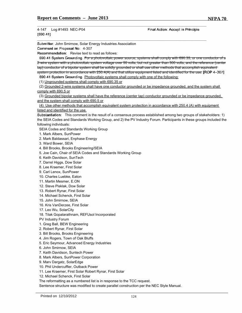
Report on Comments – June 2013 NFPA 70_______________________________________________________________________________________________4-147 Log #1493 NEC-P04
_______________________________________________________________________________________________John Smirnow, Solar Energy Industries Association
4-307Revise text to read as follows:
For a photovoltaic power source, systems shall comply with 690.35, or one conductor of a2-wire system with a photovoltaic system voltage over 50 volts, but not greater than 300 volts, and the reference (centertap) conductor of a bipolar system shall be solidly grounded or shall use other methods that accomplish equivalentsystem protection in accordance with 250.4(A) and that utilize equipment listed and identified for the use.
Photovoltaic systems shall comply with one of the following:(1) Ungrounded systems shall comply with 690.35 or(2) Grounded 2-wire systems shall have one conductor grounded or be impedance grounded, and the system shall
comply with 690.5 or(3) Grounded bipolar systems shall have the reference (center tap) conductor grounded or be impedance grounded,
and the system shall comply with 690.5 or(4) Use other methods that accomplish equivalent system protection in accordance with 250.4 (A) with equipment
listed and identified for the use.This comment is the result of a consensus process established among two groups of stakeholders: 1)
the SEIA Codes and Standards Working Group, and 2) the PV Industry Forum. Participants in these groups included thefollowing individuals:
SEIA Codes and Standards Working Group1. Mark Albers, SunPower2. Mark Baldassari, Enphase Energy3. Ward Bower, SEIA4. Bill Brooks, Brooks Engineering/SEIA5. Joe Cain, Chair of SEIA Codes and Standards Working Group6. Keith Davidson, SunTech7. Darrel Higgs, Dow Solar8. Lee Kraemer, First Solar9. Carl Lenox, SunPower10. Charles Luebke, Eaton11. Martin Mesmer, E.ON12. Steve Pisklak, Dow Solar13. Robert Rynar, First Solar14. Michael Schenck, First Solar15. John Smirnow, SEIA16. Kris VanDerzee, First Solar17. Leo Wu, SolarCity18. Tilak Gopalarathnam, REFUsol IncorporatedPV Industry Forum1. Greg Ball, BEW Engineering2. Robert Rynar, First Solar3. Bill Brooks, Brooks Engineering4. Jim Rogers, Town of Oak Bluffs5. Eric Seymour, Advanced Energy Industries6. John Smirnow, SEIA7. Keith Davidson, Suntech Power8. Mark Albers, SunPower Corporation9. Marv Dargatz, SolarEdge10. Phil Undercuffler, Outback Power11. Lee Kraemer, First Solar Robert Rynar, First Solar12. Michael Schenck, First SolarThe reformatting as a numbered list is in response to the TCC request.Sentence structure was modified to create parallel construction per the NEC Style Manual.
124Printed on 12/10/2012

Report on Comments – June 2013 NFPA 70Restricting PV systems operating over 300 volts to have only ungrounded PV arrays is unnecessary for improved
safety and imposes severe constraints on the design and development of future (demand response, intelligent) PVsystems where other renewable resources will be interacting with PV. The US has successfully and safely operatedgrounded electrical systems at 600 volts and higher for more than a century. Safety issues in grounded PV systemsare being addressed in both the UL Standards and in other sections of the NEC. This restriction, if instituted, would prevent the use of one of the more widely installed, highest efficiency PV modulesin the world. Both small residential and large commercial installations would be impacted with no improvements insafety. Technology versus Safety would likely be compromised because additional less-efficient modules would have tobe installed decreasing safety (both roof and electrical) and system reliability could be compromised.
The reference to “over 50” volts has been deleted since the list now includes all types of systems at any voltage.Removing the “solidly” requirement makes the Code language consistent with the PV inverters and other equipment
that is manufactured and listed to UL Standards where an overcurrent device is allowed to make the dc groundingbonding jumper as a part of the NEC required ground fault protection device.
Adding the allowance for impedance grounding and the reference the 690.5 adds clarity when grounded 2-wire andbipolar PV systems are installed.
Revise 690.41 to read as follows:. Photovoltaic systems shall comply with one of the following:
(1) Ungrounded systems shall comply with 690.35(2) Grounded 2-wire systems shall have one conductor grounded or be impedance grounded, and the system shall
comply with 690.5(3) Grounded bipolar systems shall have the reference (center tap) conductor grounded or be impedance grounded,
and the system shall comply with 690.5(4) Use other methods that accomplish equivalent system protection in accordance with 250.4 (A) with equipment
listed and identified for the use.The panel removed the word "or" from the items in the list.
_______________________________________________________________________________________________4-148 Log #899 NEC-P04
_______________________________________________________________________________________________Paul Kovalov, Burndy LLC
4-308Revise text to read as follows:
Devices identified and listed for bonding the metallic frames of PV modules shall bepermitted to bond the exposed metallic frames of PV modules to the metallic frames of adjacent PV modules, only whensuch PV modules are listed and identified for the purpose of grounding and bonding.
The joints connecting each separate section of a PV module frame, and the frame as a whole, are nottested or listed as bonding/grounding devices. The joints are evaluated for continuity within the frame so that aconnection to the Equipment Grounding Conductor (EGC) can be made on only one (of the typically 4) sections of thePV module frame. By bonding the frames of adjacent PV module together, without bonding them to a continuousconductor, a device not listed for grounding the metallic frames of PV modules (the connection at the corners of eachframe) is introduced into the ground path. The requirements for electrical bonds within a module frame are different fromthe requirements for bonding and grounding devices used for connection to the EGC.
This comment does not comply with Section 4.4.5(b) of the NFPA Regulations GoverningCommittee Projects in that it does not identify the document, proposal number to which the comment is directed, andparagraph of the document to which the comment is directed.
125Printed on 12/10/2012

Report on Comments – June 2013 NFPA 70_______________________________________________________________________________________________4-149 Log #1234 NEC-P04
_______________________________________________________________________________________________Richard E. Loyd, Sun Lakes, AZ
4-308aRevise text to read as follows:
Equipment Grounding conductors for PV source and PV outputcircuits shall be sized in accordance with Table 250.122 Part lVArticle 250. Where no overcurrent protective device isused in the circuit, an assumed overcurrent device rated at the PV maximum circuit current shall be used to determinethe size of wire type equipment grounding conductor in Table 250.122.Increases in equipment grounding conductor size to address voltage drop considerations shall not be required. Anequipment grounding conductor shall not be smaller than 14 AWG.
There is some who interpret the present language to limit equipment grounding to only wire types. Thischange will clarify that any suitable equipment grounding conductors listed in Section 250.118 are acceptable.
Revise text to read as follows:Equipment Grounding conductors for PV source and PV output
circuits shall be sized in accordance with Table 250.122. Where no overcurrent protective device is used in the circuit,an assumed overcurrent device rated at the PV maximum circuit current shall be used when applying Table 250.122.Increases in equipment grounding conductor size to address voltage drop considerations shall not be required. Anequipment grounding conductor shall not be smaller than 14 AWG.
The panel accept the concept and corrects the reference to Part IV Article 250 to 250.122. Thechange to "when applying" simplifies the reference to Table 250.122.
_______________________________________________________________________________________________4-150 Log #77 NEC-P04
_______________________________________________________________________________________________Technical Correlating Committee on National Electrical Code®,
4-309The Correlating Committee directs that this proposal be reconsidered and the use of the term
"solid" be clarified with respect to the use of equipment grounding conductors and grounding electrode conductors.The Correlating Committee further directs that this proposal be clarified with respect to the use of the phrase "of 6
AWG and smaller", as it applies to equipment grounding conductors and grounding electrode conductors.This is a direction from the National Electrical Code Technical Correlating Committee in accordance
with 3.4.2 and 3.4.3 of the Regulations Governing Committee Projects.
Revise proposed 690.46 text to read as follows.Equipment grounding conductors for PV modules smaller than 6
AWG shall comply with 250.120(C).Where installed in raceways, equipment grounding and grounding electrode conductors not larger than 6 AWG shall be
permitted to be solid.The panel accepts the recommendation of the Correlating Committee. The language was changed
for clarity.
126Printed on 12/10/2012

Report on Comments – June 2013 NFPA 70_______________________________________________________________________________________________4-151 Log #78 NEC-P04
_______________________________________________________________________________________________Technical Correlating Committee on National Electrical Code®,
4-310aThe Correlating Committee directs that Panel 4 clarify the panel action on this proposal by adding
the word "for" to the final phrase of the text appended to 690.47(B) as follows: "…and for the ground-fault detectionreference for ungrounded PV systems".
The Correlating Committee also directs that Panel 4 clarify the term "combined bonding grounding conductor" in theproposed revised text for 690.47(C)(3).
This is a direction from the National Electrical Code Technical Correlating Committee in accordancewith 3.4.2 and 3.4.3 of the Regulations Governing Committee Projects.
Add the following sentence to the end of existing 2011 text of 690.47(C)(3):For ungrounded systems, this conductor shall be sized in accordance with 250.122 and shall not be required to be
larger than the largest ungrounded phase conductor.
The panel revises Proposal 4-310a to remove the objectionable language as recommended by theCorrelating Committee and CMP 5. A new sentence is added to the end of existing 690.47(C)(3) to acknowledge theuse of an equipment grounding conductor for ground fault sensing on ungrounded systems.
127Printed on 12/10/2012

Report on Comments – June 2013 NFPA 70_______________________________________________________________________________________________4-152 Log #277 NEC-P04
_______________________________________________________________________________________________Code-Making Panel 5,
4-310aCode-Making Panel 5 recommends rejecting this proposal.
The proposed language is unclear and uses undefined terms such as “equipment grounding system”and “grounding bonding conductor.” It is also unclear if the proposed language modifies or enhances existingrequirements in Article 250. For example, the proposal seems to restate the requirement in Article 250 that only onegrounding electrode system is permitted for all of the wiring systems installed in a building or structure.
This comment was developed by a CMP-5 Task Group and balloted through the entire panel with the following ballotresults:
16 Eligible to Vote15 Affirmative1 Ballot Note Returned (W.J. Helfrich)
The following AFFIRMATIVE comments on vote were received:T.N. BOWMER: I agree with CMP-5’s recommendation to Reject the proposal and the CMP-5 statement. The current
language in 690.47(B) and 640.47(C)(3) are sufficiently clear.P. SIMMONS: This proposal is an example of the provisions stated in 90.3 in that general grounding and bonding
requirements reside in Article 250 and amendments or modification of the general rules can be made in Article 690.Minor editorial corrections can be made to make this proposal acceptable. The TCC made a required change to690.47(B). While it is better for Code Panels to use defined terms, it is most important that the rule is clear. If CMP-4feels the rule is important to Solar PV systems, it is suggested it be revised as follows:690.47(C)(3) Combined Direct-Current Grounding Electrode Conductor, PV Bonding Jumper,and Alternating-Current Equipment Grounding Conductor.
A combined dc grounding electrode conductor, PV bonding jumper, and ac equipment groundingconductor shall comply with all the following:
1. Be unspliced or spliced in accordance with applicable requirements of 250.64(C)2. Be connected to the connection points for the dc grounding electrode conductor or PV bonding jumper3. Be routed with the ac circuit conductors4. Be connected to the terminal bar for the grounded conductor or equipment grounding conductor terminal bar located
in the service equipment or in the first disconnecting means for a separately derived system5. Be the larger of the sizes specified by 250.122 based on the rating of the inverter output circuit overcurrent device or
in 250.168 or 250.1666. Be installed in accordance with 250.64(E) if applicable
CMP 4 acknowledges the concerns expressed by CMP 5 and the Correlating Committee. As aresult, CMP 4 acts on Comment 4-151 and retains only language that is necessary to facilitate ground fault detection onungrounded systems. The remainder of Proposal 4-310a is rejected.
See panel action and statement on Comment 4-151 which addresses the concerns of the submitter.
128Printed on 12/10/2012

Report on Comments – June 2013 NFPA 70_______________________________________________________________________________________________4-153 Log #79 NEC-P04
_______________________________________________________________________________________________Technical Correlating Committee on National Electrical Code®,
4-312The Correlating Committee directs that this proposal be clarified by adding “by a” before “connector
listed for grounding and bonding” as an editorial correction.This action will be considered a public comment.
This is a direction from the National Electrical Code Technical Correlating Committee in accordancewith 3.4.2 and 3.4.3 of the Regulations Governing Committee Projects.
The panel accepts the intent of the Correlating Committee. See panel action on Comment 4-154.
_______________________________________________________________________________________________4-154 Log #530 NEC-P04
_______________________________________________________________________________________________James F. Williams, Fairmont, WV
4-312Revise text to read as follows:
A dc grounding electrode conductor of thesize specified by 250.166 shall be run from the marked dc grounding electrode connection point to the ac groundingelectrode. Where an ac grounding electrode is not accessible, the dc grounding electrode conductor shall be connectedto the ac grounding electrode conductor in accordance with 250.64(C)(1), 250.64(C)(2), or using a connector listed forgrounding and bonding.
The “or” list lacks parallelism for the third item.
_______________________________________________________________________________________________4-155 Log #1001 NEC-P04
_______________________________________________________________________________________________David Clements, International Association of Electrical Inspectors
4-314Accept proposal 4-315 as submitted.
This concept of the proposed language should have been accepted with the recommended action toadd new text as there is currently no 690.47(D) to revise. During the 2011 code making process a proposal wassubmitted to delete this section, 4-238 Log #2509 NEC-p04. This proposal was rejected by the panel. During the rewriteof this Article, this paragraph was apparently left out and does not appear in the 2011 code. This section needs to be inthe code to make it clear that PV arrays require an additional grounding electrode system.
The assumption has been made that the correct proposal in the recommendation is 4-314.
129Printed on 12/10/2012

Report on Comments – June 2013 NFPA 70_______________________________________________________________________________________________4-156 Log #1078 NEC-P04
_______________________________________________________________________________________________John C. Wiles, Southwest Technology Development Institute, New Mexico State University
4-315Revise the proposed text as follows
Grounding electrodes shall be installed in accordance with 250.52 at the location of all ground- and pole-mountedphotovoltaic arrays. The electrodes shall be connected directly to the array frame(s) or structure. Mounting poles orstructures meeting the requirements of 250.52 shall be acceptable. The dc grounding electrode conductor shall be sizedaccording to 250.166. Bonding this grounding electrode to other grounding electrodes in the system shall not berequired. Additional electrodes are not permitted to be used as a substitute for equipment bonding or equipmentgrounding conductor requirements.
The first added sentence allows the use of the mounting poles and structures to meet this requirementwhere they meet 250.52 requirements. Adding the second sentence shown removes any confusion in this area. Therequired equipment-grounding conductor connects all grounding electrodes together. An additional bonding connectionbetween electrodes which may be hundreds or thousands of feet apart is not required or warranted, and will createparallel paths of currents in the equipment-grounding conductor. This requirement now follows practice established in250.54 and in 250.32.
The panel actions as published in the Draft NEC and the panel statements are not consistent andare confusing. The original proposal did not include roof top installations. The panel actions added roof topinstallations. The panel statement said that roof top installations were not to be included. The draft NEC follows theoriginal proposal, not the panel actions, and does not include roof top installations.We agree with the panel statement and the draft NEC.
The panel rejects the additional text: Bonding this grounding electrode to other grounding electrodes in the systemshall not be required.
The intent of the submitter is already met in Proposal 4-314 recognizes the use of mounting polesand structures.
The requirement to bond grounding electrodes to one another is only at a single building or structure not at separatelocations. This requirement is already covered in Article 250.
130Printed on 12/10/2012
Report on Comments – June 2013 NFPA 70_______________________________________________________________________________________________4-157 Log #1200 NEC-P04
_______________________________________________________________________________________________Marvin Hamon, Hamon Engineering
4-315Revise text to read as follows:
690.47(D) Additional Auxiliary Electrodes for Array Grounding. A Ggrounding electrodes shall be installed inaccordance with 250.52 and 250.54 at the location of all ground- and pole-mounted photovoltaic. The electrodes shallbe connected directly to the array frame(s) or structure. The dc grounding electrode conductor shall be sized accordingto 250.166.Additional electrodes are not permitted to be used as a substitute for equipment bonding or equipment groundingconductor requirements.
Change plural to singular to indicate that multiple grounding electrodes are not necessarily arequirement. One grounding electrode may be all that is needed and would follow the wording of 250.32.
Add the term “Auxiliary” to indicate that this grounding electrode is not required to be tied into the premises groundingelectrode system and if multiple grounding electrodes are installed they do not need to be bonded together by adedicated bonding conductor. The PV array grounding electrode system is a separate standalone structure and 250.50does not require the grounding electrode systems of different structures to be bonded together. The equipmentgrounding conductor is sized based on 250.166 and will serve to bond the electrodes in the PV array together. Aseparate bonding conductor would be duplicative. All this can be written out in the article or the wording change toAuxiliary and reference to 250.54 will do the same thing.
The panel accepts the addition of the words "auxiliary", "and 250.54" and the change to "a grounding".
See panel action and statement on Comment 4-155.
_______________________________________________________________________________________________4-158 Log #1201 NEC-P04
_______________________________________________________________________________________________Marvin Hamon, Hamon Engineering
4-315Delete text to read as follows:
690.47(D) Additional Electrodes for Array Grounding. Grounding electrodes shall be installed in accordance with250.52 at the location of all ground- and pole-mounted photovoltaic. The electrodes shall be connected directly to thearray frame(s) or structure. The dc grounding electrode conductor shall be sized according to 250.166. Additionalelectrodes are not permitted to be used as a substitute for equipment bonding or equipment grounding conductorrequirements.
Request that the CMP reject this proposal in its entirety. The substantiation given for this proposal isnot a technical substantiation but only states that the submitter thinks that the section was deleted from the 2011 NEC inerror. A review of the 2011 ROC shows that the final vote of the CMP was clearly to delete 690.47(D) from the 2011NEC.
This article wording was initially added to the 2008 NEC for the purpose of mitigating the effects of lightening strikesbut the NEC does not promulgate safety requirements relating to lightning. Article 250.54 allows the addition ofgrounding electrodes if desired in the PV array.
The panel has reinstated the requirement in 690.47(D) because the installation of auxiliarygrounding electrodes increases safety.
See panel action and statement on Comment 4-155.
131Printed on 12/10/2012
Report on Comments – June 2013 NFPA 70_______________________________________________________________________________________________4-159 Log #1506 NEC-P04
_______________________________________________________________________________________________William F. Brooks, Brooks Engineering
4-320Revise the text proposed by 4-320 with the modified text as shown:
(B) Facilities with Utility Services and PV Systems. Buildings or structures with both utility service and a photovoltaicsystem shall have a permanent plaque or directory providing the location of the service disconnecting means and thephotovoltaic system disconnecting means if not located at the same location. The marking shall be in accordance with690.31(E). For PV systems complying with 690.12, the plaque or directory shall include the following wording orequivalent: PV SYSTEM EQUIPPED WITH RAPID SHUTDOWN. OPERATION OF RAPID SHUTDOWN REDUCESVOLTAGE OF PV SYSTEM CONDUCTORS TO NO MORE THAN 30 VOLTS INSIDE BUILDING AND 10 FEET FROMARRAY. MAXIMUM VOLTAGE AT ARRAY 80VDC AFTER SHUTDOWNThe warning sign(s) or label (s) shall comply with 110.21(B).
The rewording is necessary for consistency with the significant rewording of 690.12 that is referenced in690.56(B). The words “following” and “or equivalent” were added to the sentence before the sign language so thatproducts that exceed these requirements can reword the sign to accurately state additionally where voltage is reduced.The reference to 110.21(B) was added for consistency with other additions throughout this Code.
Reject the plaque wording.Reject the last sentence in (B).Revise the proposed text to read as follows:(B) Facilities with Utility Services and PV Systems.Buildings or structures with both utility service and a PV system shall have a permanent plaque or directory providing
the location of the service disconnecting means and the PV system disconnecting means if not located at the samelocation. The warning sign(s) or label (s) shall comply with 110.21(B).
(C) Facilities with Rapid Shutdown Buildings or structures with both utility service and a PV system, complying with690.12, shall have a permanent plaque or directory including the wording:
PHOTOVOLTAIC SYSTEM EQUIPPED WITH RAPID SHUTDOWNThe plaque or directory shall be reflective and shall have all letters capitalized with a minimum height of 9.5 mm (3⁄8
in.) white on red background.The new 690.56(C) was formed entitled "Facilities with Rapid Shutdown" with revised language.
The sign configuration is according to NFPA 1, , 2012. The panel rejected the lengthy plaque wording. Thepanel rejects the last sentence in (B) since it was incapable with the requirements of 110.21(B).
_______________________________________________________________________________________________4-160 Log #80 NEC-P04
_______________________________________________________________________________________________Technical Correlating Committee on National Electrical Code®,
4-323It was the action of the Correlating Committee that this proposal be reconsidered and correlated
with the action on Proposal 4-375 as directed by the Correlating Committee.This action will be considered a public comment.
This is a direction from the National Electrical Code Technical Correlating Committee in accordancewith 3.4.2 and 3.4.3 of the Regulations Governing Committee Projects.
The panel accepts the recommendation of the Correlating Committee. CMP 4 restored Part VIII ofArticle 690 in its entirety with all associated accepted proposals (4-324, 4-325, 4-326) by panel actions taken onComments 4-192 and 4-193.
132Printed on 12/10/2012
Report on Comments – June 2013 NFPA 70_______________________________________________________________________________________________4-161 Log #81 NEC-P04
_______________________________________________________________________________________________Technical Correlating Committee on National Electrical Code®,
4-324It was the action of the Correlating Committee that this proposal be reconsidered and correlated
with the action on Proposal 13-33.This is a direction from the National Electrical Code Technical Correlating Committee in accordance
with 3.4.2 and 3.4.3 of the Regulations Governing Committee Projects.
Revise 690.71(B)(1) to read as follows:Storage batteries for dwellings shall have the cells connected so as to operate at a nominal
voltage of 50 volts or less.
The panel accepts the recommendation of the Correlating Committee.
133Printed on 12/10/2012

Report on Comments – June 2013 NFPA 70_______________________________________________________________________________________________4-162 Log #643 NEC-P04
_______________________________________________________________________________________________James T. Dollard, Jr., IBEW Local 98
4-327Continue to Accept in Principle.
This comment is submitted by a single individual and does not represent the work or input of the highvoltage task group (HVTG). This comment attempts to address concerns stated in the negative. Safety of all electricalworkers must be the first consideration when the technical committee considers raising the voltage threshold. Thissubmitter greatly appreciates the technical committee members concern for the safety of all electrical workers. I havereviewed the impact on worker safety in each of these proposals. As the safety coordinator for IBEW Local 98 inPhiladelphia, I could not support raising the voltage threshold if I felt there was a safety concern that we could notaddress. If there is any concern that the safety of electrical workers is impacted, CMP-4 should reject all proposalsseeking to raise the voltage threshold.
The work of the high voltage task group was very broad in nature. It is widely recognized and understood thatemerging technologies such as small wind and PV are breaking the 600-volt threshold making these alternative energysources more efficient. The HVTG was directed to review this issue and to submit proposals to generate a shift in NECrequirements to specifically address these new system voltages. The HVTG submitted proposals to the technicalcommittees with specific expertise to let each individual CMP make the decision on raising the voltage threshold. Weneeded a placeholder in all locations. Any CMP that felt there was a safety issue rejected the proposal. The HVTGsupported those rejections in each case. The final decision lies with the technical committee.
It is important to note that if this technical committee raises the voltage threshold from 600 to 1000-volts in the NEC,the only change is the “ voltage threshold level” of the installation requirement. This change in the voltage thresholdlevel does not permit conductors and equipment rated at 600-volts to be used at 1000-volts. That would require theconductors and equipment to be tested and listed for such use. See NFPA 70 110.3(B). There are many products thatare already listed and marked for this use.
NFPA 70E requires that all employees who face a risk of electrical hazard that is not reduced to a safe level by theapplicable electrical installation requirements be trained to understand the specific hazards they face. See 70E 110.2.Qualified persons are required. Energized work is only permitted where justified. See 130.2. Personal Protectiveequipment, including but not limited to voltage rated gloves and arc rated clothing are readily available. Trainingprograms for electrical safe work practices for voltages over 600-volts are readily available.
There are meters and other test instruments readily available for use to day at 1000-volts. It should be noted thatNFPA 70E 110.4 requires all test instruments to be properly rated and used only by qualified persons. NFPA 70E110.2(D)(1)(4)(e) requires the qualified person be trained on the proper use and limitations of the test instrument. Aquick Google search revealed the following, there are more:
Fluke 77IV, general purpose digital meter, 1000-vac, 1000-vdcIdeal 490, general-purpose digital meter, 1000-vac, 1000-vdcIn closing, I would like to repeat that if there is any concern that the safety of electrical workers is impacted, CMP-4
should reject all proposals seeking to raise the voltage threshold.
134Printed on 12/10/2012

Report on Comments – June 2013 NFPA 70_______________________________________________________________________________________________4-163 Log #644 NEC-P04
_______________________________________________________________________________________________James T. Dollard, Jr., IBEW Local 98
4-328Continue to Accept in Principle.
This comment is submitted by a single individual and does not represent the work or input of the highvoltage task group (HVTG). This comment attempts to address concerns stated in the negative. Safety of all electricalworkers must be the first consideration when the technical committee considers raising the voltage threshold. Thissubmitter greatly appreciates the technical committee members concern for the safety of all electrical workers. I havereviewed the impact on worker safety in each of these proposals. As the safety coordinator for IBEW Local 98 inPhiladelphia, I could not support raising the voltage threshold if I felt there was a safety concern that we could notaddress. If there is any concern that the safety of electrical workers is impacted, CMP-4 should reject all proposalsseeking to raise the voltage threshold.
The work of the high voltage task group was very broad in nature. It is widely recognized and understood thatemerging technologies such as small wind and PV are breaking the 600-volt threshold making these alternative energysources more efficient. The HVTG was directed to review this issue and to submit proposals to generate a shift in NECrequirements to specifically address these new system voltages. The HVTG submitted proposals to the technicalcommittees with specific expertise to let each individual CMP make the decision on raising the voltage threshold. Weneeded a placeholder in all locations. Any CMP that felt there was a safety issue rejected the proposal. The HVTGsupported those rejections in each case. The final decision lies with the technical committee.
It is important to note that if this technical committee raises the voltage threshold from 600 to 1000-volts in the NEC,the only change is the “ voltage threshold level” of the installation requirement. This change in the voltage thresholdlevel does not permit conductors and equipment rated at 600-volts to be used at 1000-volts. That would require theconductors and equipment to be tested and listed for such use. See NFPA 70 110.3(B). There are many products thatare already listed and marked for this use.
NFPA 70E requires that all employees who face a risk of electrical hazard that is not reduced to a safe level by theapplicable electrical installation requirements be trained to understand the specific hazards they face. See 70E 110.2.Qualified persons are required. Energized work is only permitted where justified. See 130.2. Personal Protectiveequipment, including but not limited to voltage rated gloves and arc rated clothing are readily available. Trainingprograms for electrical safe work practices for voltages over 600-volts are readily available.
There are meters and other test instruments readily available for use to day at 1000-volts. It should be noted thatNFPA 70E 110.4 requires all test instruments to be properly rated and used only by qualified persons. NFPA 70E110.2(D)(1)(4)(e) requires the qualified person be trained on the proper use and limitations of the test instrument. Aquick Google search revealed the following, there are more:
Fluke 77IV, general purpose digital meter, 1000-vac, 1000-vdcIdeal 490, general-purpose digital meter, 1000-vac, 1000-vdcIn closing, I would like to repeat that if there is any concern that the safety of electrical workers is impacted, CMP-4
should reject all proposals seeking to raise the voltage threshold.
135Printed on 12/10/2012

Report on Comments – June 2013 NFPA 70_______________________________________________________________________________________________4-164 Log #680 NEC-P04
_______________________________________________________________________________________________James T. Dollard, Jr., IBEW Local 98
4-327Continue to Accept in Principle.
This comment is submitted on behalf of the high voltage task to provide additional substantiation asdirected by the Correlating Committee.
The High Voltage Task Group (HVTG) was charged with developing recommendations throughout the NEC to providethe code user with prescriptive requirements for high voltage installations. The task group charge was to identify holes inthe code with respect to installations operating at over 600-volts and address them with recommended requirements toallow for uniform installation and enforcement. Small Wind Electric Systems and Solar Photovoltaic (PV) Systems arecurrently being installed at DC voltages over 600V up to and including 1000V, 1200V, 1500V, and 2000V DC. TheseDC systems are expanding and have become a more integral part of many structures. Small Wind Electric Systems andSolar Photovoltaic (PV) Systems are employed regularly in, and on all types of structures from dwellings units, to largeretail and high rise construction.
The first direction that the HVTG took was to simply suggest revisions in Chapter 6 for Special Equipment. It isextremely important to fully understand the outline form of the NEC. 90.3 mandates that Chapters 1 through 4 applygenerally and Chapters 5, 6 & 7 are special and serve only to modify or supplement the rules in Chapters 1 through 4.The HVTG quickly realized that it was not feasible to address all of the installation requirements in Chapter 6. The workneeds to be done throughout the NEC. The special systems in Chapter 6 are built primarily upon Chapters 1 through 4with the Chapter 6 requirements providing only modifications or supplemental requirements. A quick review of the ULWhite-book for electrical products will uncover that UL has many products that are utilized in these systems rated at andabove 600-volts including but not limited to, 600Vdc terminal blocks, 1000Vdc PV switches, 1500Vdc PV fuses, and2000V PV wiring. Product listings provide permitted uses and restrictions on a given product. The NEC must recognizethose products through installation requirements. Electrical safety in the home, workplace and in all venues dependsupon installation requirements to ensure that all persons and property are not exposed to the hazards of electricity. Thesuccess of this code hinges on three things (1) product standards, (2) installation requirements and (3) enforcement.The NEC needs to recognize emerging technologies that are operating at over 600-volts. Everyone needs to play a rolein this transition. The present NEC requirements would literally require that a PV system operating at 750-volts DCutilize a disconnecting means rated at 5 kV. The manufacturers, research and testing laboratories and the NEC mustwork together to develop installation requirements and product standards to support these emerging technologies.
Moving the NEC threshold from 600 volts to 1000 volts will not, by itself, allow the immediate installation of systems at1000-volts. Equipment must first be tested and found acceptable for use at the higher voltage(s). The testing and listingof equipment will not, by itself, allow for the installation of 1000 volt-systems. The NEC must include prescriptiverequirements to permit the installation of these 1000-volt systems. It will take both tested/listed equipment and aninstallation code to meet the needs of these emerging technologies that society demands. The installation code shouldbe the NEC.
Moving the NEC to 1000 volts is just the beginning. The desire to keep increasing efficiencies will continue to drive upthe system voltages. We are beginning to see 1200, 1500, and 2000-volt systems. 2500 volts cannot be far down theroad. Most equipment standards are still at 600 volts and will need to be upgraded also.
If the NEC does not adequately address systems over 600 volts, some other standard will. If we want to control thefuture safety of installations over 600 volts we need to address these issues today.
136Printed on 12/10/2012

Report on Comments – June 2013 NFPA 70_______________________________________________________________________________________________4-165 Log #681 NEC-P04
_______________________________________________________________________________________________James T. Dollard, Jr., IBEW Local 98
4-328Continue to Accept in Principle.
This comment is submitted on behalf of the high voltage task to provide additional substantiation asdirected by the Correlating Committee.
The High Voltage Task Group (HVTG) was charged with developing recommendations throughout the NEC to providethe code user with prescriptive requirements for high voltage installations. The task group charge was to identify holes inthe code with respect to installations operating at over 600-volts and address them with recommended requirements toallow for uniform installation and enforcement. Small Wind Electric Systems and Solar Photovoltaic (PV) Systems arecurrently being installed at DC voltages over 600V up to and including 1000V, 1200V, 1500V, and 2000V DC. TheseDC systems are expanding and have become a more integral part of many structures. Small Wind Electric Systems andSolar Photovoltaic (PV) Systems are employed regularly in, and on all types of structures from dwellings units, to largeretail and high rise construction.
The first direction that the HVTG took was to simply suggest revisions in Chapter 6 for Special Equipment. It isextremely important to fully understand the outline form of the NEC. 90.3 mandates that Chapters 1 through 4 applygenerally and Chapters 5, 6 & 7 are special and serve only to modify or supplement the rules in Chapters 1 through 4.The HVTG quickly realized that it was not feasible to address all of the installation requirements in Chapter 6. The workneeds to be done throughout the NEC. The special systems in Chapter 6 are built primarily upon Chapters 1 through 4with the Chapter 6 requirements providing only modifications or supplemental requirements. A quick review of the ULWhite-book for electrical products will uncover that UL has many products that are utilized in these systems rated at andabove 600-volts including but not limited to, 600Vdc terminal blocks, 1000Vdc PV switches, 1500Vdc PV fuses, and2000V PV wiring. Product listings provide permitted uses and restrictions on a given product. The NEC must recognizethose products through installation requirements. Electrical safety in the home, workplace and in all venues dependsupon installation requirements to ensure that all persons and property are not exposed to the hazards of electricity. Thesuccess of this code hinges on three things (1) product standards, (2) installation requirements and (3) enforcement.The NEC needs to recognize emerging technologies that are operating at over 600-volts. Everyone needs to play a rolein this transition. The present NEC requirements would literally require that a PV system operating at 750-volts DCutilize a disconnecting means rated at 5 kV. The manufacturers, research and testing laboratories and the NEC mustwork together to develop installation requirements and product standards to support these emerging technologies.
Moving the NEC threshold from 600 volts to 1000 volts will not, by itself, allow the immediate installation of systems at1000-volts. Equipment must first be tested and found acceptable for use at the higher voltage(s). The testing and listingof equipment will not, by itself, allow for the installation of 1000 volt-systems. The NEC must include prescriptiverequirements to permit the installation of these 1000-volt systems. It will take both tested/listed equipment and aninstallation code to meet the needs of these emerging technologies that society demands. The installation code shouldbe the NEC.
Moving the NEC to 1000 volts is just the beginning. The desire to keep increasing efficiencies will continue to drive upthe system voltages. We are beginning to see 1200, 1500, and 2000-volt systems. 2500 volts cannot be far down theroad. Most equipment standards are still at 600 volts and will need to be upgraded also.
If the NEC does not adequately address systems over 600 volts, some other standard will. If we want to control thefuture safety of installations over 600 volts we need to address these issues today.
137Printed on 12/10/2012
Report on Comments – June 2013 NFPA 70_______________________________________________________________________________________________4-166 Log #1288 NEC-P04
_______________________________________________________________________________________________Jim Eichner, Schneider Electric - Solar Business
4-327None provided.
Schneider Electric supports the increase of the low voltage limit from 600V to 1000V in proposal 4-327and throughout the NEC. In particular for PV this change will provide relief from requirements in Art. 490 that areexcessive for PV systems that do not operate at the higher voltage levels that Art. 490 was originally intended to cover.We recommend that further increases for PV systems up to 1500V or 2000V be considered in future code cycles.
The comment has no recommendation. This comment does not comply with Section 4.4.5(c) of theNFPA Regulations Governing Committee Projects in that it does not provide text of the comment, including the wordingto be added, revised (and how revised), or deleted.
_______________________________________________________________________________________________4-167 Log #463 NEC-P04
_______________________________________________________________________________________________Marcelo M. Hirschler, GBH International
4-332Revise text to read as follows:
An electrochemical system that consumes fuel to produce an electric current. In such cells the The mainchemical reaction used in a fuel cell for producing electric power is not combustion. However, there may be sources ofcombustion used within the overall fuel cell system such as reformers/fuel processors.
I accept the concept that NEC definitions are not required to be in single sentences. However thisdefinition contains the defined term and the NEC manual of style does not permit the definition to contain the definedterm. Definitions are not requirements. The proposed changes eliminate the defined term. If the CMP believes that thisinformation is a requirement it should place it somewhere else in Article 692.The NEC Manual of Style states as follows:
Definitions. Definitions shall be in alphabetical order and shall not contain the term that is being defined.Definitions shall not contain requirements or recommendations.Suggested informational notes as an alternative:
: The main chemical reaction used in a fuel cell for producing electric power is not combustion.However, there may be sources of combustion used within the overall fuel cell system such as reformers/fuelprocessors.
138Printed on 12/10/2012

Report on Comments – June 2013 NFPA 70_______________________________________________________________________________________________4-168 Log #464 NEC-P04
_______________________________________________________________________________________________Marcelo M. Hirschler, GBH International
4-333Revise text to read as follows:
The complete aggregate of equipment used to convert chemical fuel into usable electricity, andtypically consisting . A fuel cell system typically consists of a reformer, stack, power inverter, and auxiliary equipment.
I accept the concept that NEC definitions are not required to be in single sentences. However thisdefinition contains the defined term and the NEC manual of style does not permit the definition to contain the definedterm. Definitions are not requirements. The proposed changes eliminate the defined term. If the CMP believes that thisinformation is a requirement it should place it somewhere else in Article 692.The NEC Manual of Style states as follows:
Definitions. Definitions shall be in alphabetical order and shall not contain the term that is being defined.Definitions shall not contain requirements or recommendations.Suggested informational notes as an alternative:
: A fuel cell system typically consists of a reformer, stack, power inverter, and auxiliary equipment.
_______________________________________________________________________________________________4-169 Log #465 NEC-P04
_______________________________________________________________________________________________Marcelo M. Hirschler, GBH International
4-335Revise text to read as follows:
The conductors used to connect the fuel cell system to its electrical point of delivery. In the case ofsites that have series- or parallel-connected multiple units, the term also refers to the conductors used toelectrically interconnect the fuel cell system(s).
: In the case of sites that have series- or parallel-connected multiple units, the term alsorefers to the conductors used to electrically interconnect the fuel cell system(s).
I accept the concept that NEC definitions are not required to be in single sentences. However thisdefinition contains the defined term and the NEC manual of style does not permit the definition to contain the definedterm. Definitions are not requirements. If the CMP believes that this information is a requirement it should place itsomewhere else in Article 692.The NEC Manual of Style states as follows:
Definitions. Definitions shall be in alphabetical order and shall not contain the term that is being defined.Definitions shall not contain requirements or recommendations.
139Printed on 12/10/2012

Report on Comments – June 2013 NFPA 70_______________________________________________________________________________________________4-170 Log #645 NEC-P04
_______________________________________________________________________________________________James T. Dollard, Jr., IBEW Local 98
4-342Continue to Accept in Principle.
This comment is submitted by a single individual and does not represent the work or input of the highvoltage task group (HVTG). This comment attempts to address concerns stated in the negative. Safety of all electricalworkers must be the first consideration when the technical committee considers raising the voltage threshold. Thissubmitter greatly appreciates the technical committee members concern for the safety of all electrical workers. I havereviewed the impact on worker safety in each of these proposals. As the safety coordinator for IBEW Local 98 inPhiladelphia, I could not support raising the voltage threshold if I felt there was a safety concern that we could notaddress. If there is any concern that the safety of electrical workers is impacted, CMP-4 should reject all proposalsseeking to raise the voltage threshold.
The work of the high voltage task group was very broad in nature. It is widely recognized and understood thatemerging technologies such as small wind and PV are breaking the 600-volt threshold making these alternative energysources more efficient. The HVTG was directed to review this issue and to submit proposals to generate a shift in NECrequirements to specifically address these new system voltages. The HVTG submitted proposals to the technicalcommittees with specific expertise to let each individual CMP make the decision on raising the voltage threshold. Weneeded a placeholder in all locations. Any CMP that felt there was a safety issue rejected the proposal. The HVTGsupported those rejections in each case. The final decision lies with the technical committee.
It is important to note that if this technical committee raises the voltage threshold from 600 to 1000-volts in the NEC,the only change is the “ voltage threshold level” of the installation requirement. This change in the voltage thresholdlevel does not permit conductors and equipment rated at 600-volts to be used at 1000-volts. That would require theconductors and equipment to be tested and listed for such use. See NFPA 70 110.3(B). There are many products thatare already listed and marked for this use.
NFPA 70E requires that all employees who face a risk of electrical hazard that is not reduced to a safe level by theapplicable electrical installation requirements be trained to understand the specific hazards they face. See 70E 110.2.Qualified persons are required. Energized work is only permitted where justified. See 130.2. Personal Protectiveequipment, including but not limited to voltage rated gloves and arc rated clothing are readily available. Trainingprograms for electrical safe work practices for voltages over 600-volts are readily available.
There are meters and other test instruments readily available for use to day at 1000-volts. It should be noted thatNFPA 70E 110.4 requires all test instruments to be properly rated and used only by qualified persons. NFPA 70E110.2(D)(1)(4)(e) requires the qualified person be trained on the proper use and limitations of the test instrument. Aquick Google search revealed the following, there are more:
Fluke 77IV, general purpose digital meter, 1000-vac, 1000-vdcIdeal 490, general-purpose digital meter, 1000-vac, 1000-vdcIn closing, I would like to repeat that if there is any concern that the safety of electrical workers is impacted, CMP-4
should reject all proposals seeking to raise the voltage threshold.
140Printed on 12/10/2012

Report on Comments – June 2013 NFPA 70_______________________________________________________________________________________________4-171 Log #646 NEC-P04
_______________________________________________________________________________________________James T. Dollard, Jr., IBEW Local 98
4-343Continue to Accept in Principle.
This comment is submitted by a single individual and does not represent the work or input of the highvoltage task group (HVTG). This comment attempts to address concerns stated in the negative. Safety of all electricalworkers must be the first consideration when the technical committee considers raising the voltage threshold. Thissubmitter greatly appreciates the technical committee members concern for the safety of all electrical workers. I havereviewed the impact on worker safety in each of these proposals. As the safety coordinator for IBEW Local 98 inPhiladelphia, I could not support raising the voltage threshold if I felt there was a safety concern that we could notaddress. If there is any concern that the safety of electrical workers is impacted, CMP-4 should reject all proposalsseeking to raise the voltage threshold.
The work of the high voltage task group was very broad in nature. It is widely recognized and understood thatemerging technologies such as small wind and PV are breaking the 600-volt threshold making these alternative energysources more efficient. The HVTG was directed to review this issue and to submit proposals to generate a shift in NECrequirements to specifically address these new system voltages. The HVTG submitted proposals to the technicalcommittees with specific expertise to let each individual CMP make the decision on raising the voltage threshold. Weneeded a placeholder in all locations. Any CMP that felt there was a safety issue rejected the proposal. The HVTGsupported those rejections in each case. The final decision lies with the technical committee.
It is important to note that if this technical committee raises the voltage threshold from 600 to 1000-volts in the NEC,the only change is the “ voltage threshold level” of the installation requirement. This change in the voltage thresholdlevel does not permit conductors and equipment rated at 600-volts to be used at 1000-volts. That would require theconductors and equipment to be tested and listed for such use. See NFPA 70 110.3(B). There are many products thatare already listed and marked for this use.
NFPA 70E requires that all employees who face a risk of electrical hazard that is not reduced to a safe level by theapplicable electrical installation requirements be trained to understand the specific hazards they face. See 70E 110.2.Qualified persons are required. Energized work is only permitted where justified. See 130.2. Personal Protectiveequipment, including but not limited to voltage rated gloves and arc rated clothing are readily available. Trainingprograms for electrical safe work practices for voltages over 600-volts are readily available.
There are meters and other test instruments readily available for use to day at 1000-volts. It should be noted thatNFPA 70E 110.4 requires all test instruments to be properly rated and used only by qualified persons. NFPA 70E110.2(D)(1)(4)(e) requires the qualified person be trained on the proper use and limitations of the test instrument. Aquick Google search revealed the following, there are more:
Fluke 77IV, general purpose digital meter, 1000-vac, 1000-vdcIdeal 490, general-purpose digital meter, 1000-vac, 1000-vdcIn closing, I would like to repeat that if there is any concern that the safety of electrical workers is impacted, CMP-4
should reject all proposals seeking to raise the voltage threshold.
141Printed on 12/10/2012

Report on Comments – June 2013 NFPA 70_______________________________________________________________________________________________4-172 Log #682 NEC-P04
_______________________________________________________________________________________________James T. Dollard, Jr., IBEW Local 98
4-342Continue to Accept in Principle.
This comment is submitted on behalf of the high voltage task to provide additional substantiation asdirected by the Correlating Committee.
The High Voltage Task Group (HVTG) was charged with developing recommendations throughout the NEC to providethe code user with prescriptive requirements for high voltage installations. The task group charge was to identify holes inthe code with respect to installations operating at over 600-volts and address them with recommended requirements toallow for uniform installation and enforcement. Small Wind Electric Systems and Solar Photovoltaic (PV) Systems arecurrently being installed at DC voltages over 600V up to and including 1000V, 1200V, 1500V, and 2000V DC. TheseDC systems are expanding and have become a more integral part of many structures. Small Wind Electric Systems andSolar Photovoltaic (PV) Systems are employed regularly in, and on all types of structures from dwellings units, to largeretail and high rise construction.
The first direction that the HVTG took was to simply suggest revisions in Chapter 6 for Special Equipment. It isextremely important to fully understand the outline form of the NEC. 90.3 mandates that Chapters 1 through 4 applygenerally and Chapters 5, 6 & 7 are special and serve only to modify or supplement the rules in Chapters 1 through 4.The HVTG quickly realized that it was not feasible to address all of the installation requirements in Chapter 6. The workneeds to be done throughout the NEC. The special systems in Chapter 6 are built primarily upon Chapters 1 through 4with the Chapter 6 requirements providing only modifications or supplemental requirements. A quick review of the ULWhite-book for electrical products will uncover that UL has many products that are utilized in these systems rated at andabove 600-volts including but not limited to, 600Vdc terminal blocks, 1000Vdc PV switches, 1500Vdc PV fuses, and2000V PV wiring. Product listings provide permitted uses and restrictions on a given product. The NEC must recognizethose products through installation requirements. Electrical safety in the home, workplace and in all venues dependsupon installation requirements to ensure that all persons and property are not exposed to the hazards of electricity. Thesuccess of this code hinges on three things (1) product standards, (2) installation requirements and (3) enforcement.The NEC needs to recognize emerging technologies that are operating at over 600-volts. Everyone needs to play a rolein this transition. The present NEC requirements would literally require that a PV system operating at 750-volts DCutilize a disconnecting means rated at 5 kV. The manufacturers, research and testing laboratories and the NEC mustwork together to develop installation requirements and product standards to support these emerging technologies.
Moving the NEC threshold from 600 volts to 1000 volts will not, by itself, allow the immediate installation of systems at1000-volts. Equipment must first be tested and found acceptable for use at the higher voltage(s). The testing and listingof equipment will not, by itself, allow for the installation of 1000 volt-systems. The NEC must include prescriptiverequirements to permit the installation of these 1000-volt systems. It will take both tested/listed equipment and aninstallation code to meet the needs of these emerging technologies that society demands. The installation code shouldbe the NEC.
Moving the NEC to 1000 volts is just the beginning. The desire to keep increasing efficiencies will continue to drive upthe system voltages. We are beginning to see 1200, 1500, and 2000-volt systems. 2500 volts cannot be far down theroad. Most equipment standards are still at 600 volts and will need to be upgraded also.
If the NEC does not adequately address systems over 600 volts, some other standard will. If we want to control thefuture safety of installations over 600 volts we need to address these issues today.
142Printed on 12/10/2012

Report on Comments – June 2013 NFPA 70_______________________________________________________________________________________________4-173 Log #683 NEC-P04
_______________________________________________________________________________________________James T. Dollard, Jr., IBEW Local 98
4-343Continue to Accept in Principle.
This comment is submitted on behalf of the high voltage task to provide additional substantiation asdirected by the Correlating Committee.
The High Voltage Task Group (HVTG) was charged with developing recommendations throughout the NEC to providethe code user with prescriptive requirements for high voltage installations. The task group charge was to identify holes inthe code with respect to installations operating at over 600-volts and address them with recommended requirements toallow for uniform installation and enforcement. Small Wind Electric Systems and Solar Photovoltaic (PV) Systems arecurrently being installed at DC voltages over 600V up to and including 1000V, 1200V, 1500V, and 2000V DC. TheseDC systems are expanding and have become a more integral part of many structures. Small Wind Electric Systems andSolar Photovoltaic (PV) Systems are employed regularly in, and on all types of structures from dwellings units, to largeretail and high rise construction.
The first direction that the HVTG took was to simply suggest revisions in Chapter 6 for Special Equipment. It isextremely important to fully understand the outline form of the NEC. 90.3 mandates that Chapters 1 through 4 applygenerally and Chapters 5, 6 & 7 are special and serve only to modify or supplement the rules in Chapters 1 through 4.The HVTG quickly realized that it was not feasible to address all of the installation requirements in Chapter 6. The workneeds to be done throughout the NEC. The special systems in Chapter 6 are built primarily upon Chapters 1 through 4with the Chapter 6 requirements providing only modifications or supplemental requirements. A quick review of the ULWhite-book for electrical products will uncover that UL has many products that are utilized in these systems rated at andabove 600-volts including but not limited to, 600Vdc terminal blocks, 1000Vdc PV switches, 1500Vdc PV fuses, and2000V PV wiring. Product listings provide permitted uses and restrictions on a given product. The NEC must recognizethose products through installation requirements. Electrical safety in the home, workplace and in all venues dependsupon installation requirements to ensure that all persons and property are not exposed to the hazards of electricity. Thesuccess of this code hinges on three things (1) product standards, (2) installation requirements and (3) enforcement.The NEC needs to recognize emerging technologies that are operating at over 600-volts. Everyone needs to play a rolein this transition. The present NEC requirements would literally require that a PV system operating at 750-volts DCutilize a disconnecting means rated at 5 kV. The manufacturers, research and testing laboratories and the NEC mustwork together to develop installation requirements and product standards to support these emerging technologies.
Moving the NEC threshold from 600 volts to 1000 volts will not, by itself, allow the immediate installation of systems at1000-volts. Equipment must first be tested and found acceptable for use at the higher voltage(s). The testing and listingof equipment will not, by itself, allow for the installation of 1000 volt-systems. The NEC must include prescriptiverequirements to permit the installation of these 1000-volt systems. It will take both tested/listed equipment and aninstallation code to meet the needs of these emerging technologies that society demands. The installation code shouldbe the NEC.
Moving the NEC to 1000 volts is just the beginning. The desire to keep increasing efficiencies will continue to drive upthe system voltages. We are beginning to see 1200, 1500, and 2000-volt systems. 2500 volts cannot be far down theroad. Most equipment standards are still at 600 volts and will need to be upgraded also.
If the NEC does not adequately address systems over 600 volts, some other standard will. If we want to control thefuture safety of installations over 600 volts we need to address these issues today.
143Printed on 12/10/2012

Report on Comments – June 2013 NFPA 70_______________________________________________________________________________________________4-174 Log #466 NEC-P04
_______________________________________________________________________________________________Marcelo M. Hirschler, GBH International
4-348Revise text to read as follows:
The wind turbine’s output power at a wind speed of 11 m/s (24.6 mph). If a turbine produces morepower at lower wind speeds, the rated power is the wind turbine’s output power at a wind speed less than 11 m/s thatproduces the greatest output power.
The method for measuring wind turbine power output is specified in IEC 61400-12-1,.
Rated power shall be the wind turbine’s output power at a wind speed of 11 m/s (24.6 mph), except as indicatedin 694.4.2.
If a turbine produces more power at lower wind speeds, the rated power shall be the wind turbine’s outputpower at a wind speed less than 11 m/s that produces the greatest output power.
The method for measuring wind turbine power output is specified in IEC 61400-12-1,.
I accept the concept that NEC definitions are not required to be in single sentences. However thisdefinition contains the defined term and the NEC manual of style does not permit the definition to contain the definedterm. It also contains requirements not allowed in definitions. It is probably best to eliminate this from the definitionsection altogether and incorporate this information as a requirement somewhere else in Article 694, for example as694.4.The NEC Manual of Style states as follows:
Definitions. Definitions shall be in alphabetical order and shall not contain the term that is being defined.Definitions shall not contain requirements or recommendations.
Reject moving definition out of 690.2Revise rated power definition to read as follows:Rated Power. The output power of a wind turbine at its rated wind speed.Informational Note: The method for measuring wind turbine power output is specified in IEC 61400-12-1, Power
Performance Measurements of Electricity Producing Wind Turbines.
The panel accepts the submitter’s proposal to correct the style manual infraction. The paneleliminated extraneous text of product specific wind speed ratings that is better addressed in product standards. As 694applies to both large and small turbines, the revised text is now correct for all turbines. Additional proposed sections areunnecessary.
Style Manual 2.2.2.2 requires definitions to be in section .2.
_______________________________________________________________________________________________4-175 Log #82 NEC-P04
_______________________________________________________________________________________________Technical Correlating Committee on National Electrical Code®,
4-353The Correlating Committee directs that the panel clarify the action on this proposal to correlate with
the panel action taken on Proposal 4-354.This is a direction from the National Electrical Code Technical Correlating Committee in accordance
with 3.4.2 and 3.4.3 of the Regulations Governing Committee Projects.
The panel accepts the recommendation of the Correlating Committee. The panel action onComment 4-178 addresses the Correlating Committee's concerns.
144Printed on 12/10/2012

Report on Comments – June 2013 NFPA 70_______________________________________________________________________________________________4-176 Log #83 NEC-P04
_______________________________________________________________________________________________Technical Correlating Committee on National Electrical Code®,
4-354The Correlating Committee directs that the panel clarify the action on this proposal to correlate with
the Panel action taken on Proposal 4-353.This is a direction from the National Electrical Code Technical Correlating Committee in accordance
with 3.4.2 and 3.4.3 of the Regulations Governing Committee Projects.
The panel accepts the recommendation of the Correlating Committee. The panel action onComment 4-178 addresses the Correlating Committee's concerns.
_______________________________________________________________________________________________4-177 Log #1455 NEC-P04
_______________________________________________________________________________________________Robert H. Wills, Intergrid, LLC
4-353, 4-354Revise Clause 694.7(B) as follows:
Inverters used in small w Wind electric systems electrical equipment, electrical subassemblies andelectrical components shall be identified and listed for the application.
(Deletes are from 4-354. Inserts are new to this comment)The original (2011) language was “Inverters used in small wind electric systems shall be identified and
listed for the application.”. The intent of the change is to require that other equipment be listed, but the changeproposed in 4-354 resulted in a much broader requirement – potentially that equipment, subassemblies andcomponents (including mechanical and passive components, nuts and bolts..) would need to be listed. The changeproposed here clarifies that the listing requirement is only for electrical devices. The repeated use of the word “electrical”is awkward, but does eliminate ambiguity.
See panel action and statement on Comment 4-178 which addresses the submitter's concerns.
145Printed on 12/10/2012

Report on Comments – June 2013 NFPA 70_______________________________________________________________________________________________4-178 Log #1456 NEC-P04
_______________________________________________________________________________________________Robert H. Wills, Intergrid, LLC
4-353, 4-354Revise Clause 694.7(B) as follows:
Inverters used in small w Wind electric systems equipment, subassemblies components shall beidentified and listed for the application.
The original (2011) language was “Inverters used in small wind electric systems shall be identified andlisted for the application.”.
Proposal 4-354 broadened the scope to include all equipment, subassemblies and components.This has two problems:1/ it implies that non-electrical components are required to be listed2/ it implies that individual components are required to be listed even if the complete wind electric system is listed “as a
system”. This is akin to requiring that all components in a listed TV be themselves listed.This change proposed here encompasses the intent of proposal 4-353 and 4-354 (that NRTLs review and list wind
electric systems for safety), without the problems noted above.
Revise 694.7(B) Equipment to read as follows:694.7(B) Equipment. Wind electric systems shall be listed and labeled for the application.Informational Note: Compliance with this requirement may be achieved by field evaluation.
The addition of the words "and labeled" addresses Comment 4-175. The term "labeled" is usedrather than "marked" as the former is a defined term. The informational note was added to recognize the possible needfor field evaluations of wind turbines.
_______________________________________________________________________________________________4-179 Log #84 NEC-P04
_______________________________________________________________________________________________Technical Correlating Committee on National Electrical Code®,
4-355The Correlating Committee directs that the panel clarify the action on this proposal because it has
introduced changes to the existing text other than what is shown legislatively.The Correlating Committee further directs that the accepted text shall comply with the NEC Style Manual.
This is a direction from the National Electrical Code Technical Correlating Committee in accordancewith 3.4.2 and 3.4.3 of the Regulations Governing Committee Projects.
The panel accepts the recommendation of the Correlating Committee. See panel action onComment 4-180.
_______________________________________________________________________________________________4-180 Log #1573 NEC-P04
_______________________________________________________________________________________________Frederic P. Hartwell, Hartwell Electrical Services, Inc.
4-355Reject the proposal.
The submitter notes that the text that was imported for this proposal did not correctly correspond tocurrent (2011) NEC text, and the actual wording is correct. The submitter apologizes for the error.
146Printed on 12/10/2012

Report on Comments – June 2013 NFPA 70_______________________________________________________________________________________________4-181 Log #647 NEC-P04
_______________________________________________________________________________________________James T. Dollard, Jr., IBEW Local 98
4-357Continue to Accept in Principle.
This comment is submitted by a single individual and does not represent the work or input of the highvoltage task group (HVTG). This comment attempts to address concerns stated in the negative. Safety of all electricalworkers must be the first consideration when the technical committee considers raising the voltage threshold. Thissubmitter greatly appreciates the technical committee members concern for the safety of all electrical workers. I havereviewed the impact on worker safety in each of these proposals. As the safety coordinator for IBEW Local 98 inPhiladelphia, I could not support raising the voltage threshold if I felt there was a safety concern that we could notaddress. If there is any concern that the safety of electrical workers is impacted, CMP-4 should reject all proposalsseeking to raise the voltage threshold.
The work of the high voltage task group was very broad in nature. It is widely recognized and understood thatemerging technologies such as small wind and PV are breaking the 600-volt threshold making these alternative energysources more efficient. The HVTG was directed to review this issue and to submit proposals to generate a shift in NECrequirements to specifically address these new system voltages. The HVTG submitted proposals to the technicalcommittees with specific expertise to let each individual CMP make the decision on raising the voltage threshold. Weneeded a placeholder in all locations. Any CMP that felt there was a safety issue rejected the proposal. The HVTGsupported those rejections in each case. The final decision lies with the technical committee.
It is important to note that if this technical committee raises the voltage threshold from 600 to 1000-volts in the NEC,the only change is the “ voltage threshold level” of the installation requirement. This change in the voltage thresholdlevel does not permit conductors and equipment rated at 600-volts to be used at 1000-volts. That would require theconductors and equipment to be tested and listed for such use. See NFPA 70 110.3(B). There are many products thatare already listed and marked for this use.
NFPA 70E requires that all employees who face a risk of electrical hazard that is not reduced to a safe level by theapplicable electrical installation requirements be trained to understand the specific hazards they face. See 70E 110.2.Qualified persons are required. Energized work is only permitted where justified. See 130.2. Personal Protectiveequipment, including but not limited to voltage rated gloves and arc rated clothing are readily available. Trainingprograms for electrical safe work practices for voltages over 600-volts are readily available.
There are meters and other test instruments readily available for use to day at 1000-volts. It should be noted thatNFPA 70E 110.4 requires all test instruments to be properly rated and used only by qualified persons. NFPA 70E110.2(D)(1)(4)(e) requires the qualified person be trained on the proper use and limitations of the test instrument. Aquick Google search revealed the following, there are more:
Fluke 77IV, general purpose digital meter, 1000-vac, 1000-vdcIdeal 490, general-purpose digital meter, 1000-vac, 1000-vdcIn closing, I would like to repeat that if there is any concern that the safety of electrical workers is impacted, CMP-4
should reject all proposals seeking to raise the voltage threshold.
The panel action on the proposal was accept in part not accept in principle.
147Printed on 12/10/2012

Report on Comments – June 2013 NFPA 70_______________________________________________________________________________________________4-182 Log #684 NEC-P04
_______________________________________________________________________________________________James T. Dollard, Jr., IBEW Local 98
4-357Continue to Accept in Part.
This comment is submitted on behalf of the high voltage task to provide additional substantiation asdirected by the Correlating Committee.
The High Voltage Task Group (HVTG) was charged with developing recommendations throughout the NEC to providethe code user with prescriptive requirements for high voltage installations. The task group charge was to identify holes inthe code with respect to installations operating at over 600-volts and address them with recommended requirements toallow for uniform installation and enforcement. Small Wind Electric Systems and Solar Photovoltaic (PV) Systems arecurrently being installed at DC voltages over 600V up to and including 1000V, 1200V, 1500V, and 2000V DC. TheseDC systems are expanding and have become a more integral part of many structures. Small Wind Electric Systems andSolar Photovoltaic (PV) Systems are employed regularly in, and on all types of structures from dwellings units, to largeretail and high rise construction.
The first direction that the HVTG took was to simply suggest revisions in Chapter 6 for Special Equipment. It isextremely important to fully understand the outline form of the NEC. 90.3 mandates that Chapters 1 through 4 applygenerally and Chapters 5, 6 & 7 are special and serve only to modify or supplement the rules in Chapters 1 through 4.The HVTG quickly realized that it was not feasible to address all of the installation requirements in Chapter 6. The workneeds to be done throughout the NEC. The special systems in Chapter 6 are built primarily upon Chapters 1 through 4with the Chapter 6 requirements providing only modifications or supplemental requirements. A quick review of the ULWhite-book for electrical products will uncover that UL has many products that are utilized in these systems rated at andabove 600-volts including but not limited to, 600Vdc terminal blocks, 1000Vdc PV switches, 1500Vdc PV fuses, and2000V PV wiring. Product listings provide permitted uses and restrictions on a given product. The NEC must recognizethose products through installation requirements. Electrical safety in the home, workplace and in all venues dependsupon installation requirements to ensure that all persons and property are not exposed to the hazards of electricity. Thesuccess of this code hinges on three things (1) product standards, (2) installation requirements and (3) enforcement.The NEC needs to recognize emerging technologies that are operating at over 600-volts. Everyone needs to play a rolein this transition. The present NEC requirements would literally require that a PV system operating at 750-volts DCutilize a disconnecting means rated at 5 kV. The manufacturers, research and testing laboratories and the NEC mustwork together to develop installation requirements and product standards to support these emerging technologies.
Moving the NEC threshold from 600 volts to 1000 volts will not, by itself, allow the immediate installation of systems at1000-volts. Equipment must first be tested and found acceptable for use at the higher voltage(s). The testing and listingof equipment will not, by itself, allow for the installation of 1000 volt-systems. The NEC must include prescriptiverequirements to permit the installation of these 1000-volt systems. It will take both tested/listed equipment and aninstallation code to meet the needs of these emerging technologies that society demands. The installation code shouldbe the NEC.
Moving the NEC to 1000 volts is just the beginning. The desire to keep increasing efficiencies will continue to drive upthe system voltages. We are beginning to see 1200, 1500, and 2000-volt systems. 2500 volts cannot be far down theroad. Most equipment standards are still at 600 volts and will need to be upgraded also.
If the NEC does not adequately address systems over 600 volts, some other standard will. If we want to control thefuture safety of installations over 600 volts we need to address these issues today.
148Printed on 12/10/2012

Report on Comments – June 2013 NFPA 70_______________________________________________________________________________________________4-183 Log #157 NEC-P04
_______________________________________________________________________________________________Technical Correlating Committee on National Electrical Code®,
9-181cIt was the action of the Correlating Committee that this proposal be referred to Code-Making Panel
4 for action in Article 694.This is a direction from the National Electrical Code Technical Correlating Committee in accordance
with 3.4.2 and 3.4.3 of the Regulations Governing Committee Projects.
_______________________________________________________________________________________________4-184 Log #531 NEC-P04
_______________________________________________________________________________________________James F. Williams, Fairmont, WV
4-364aRevise text to read as follows:
Why make it hard?
The convention of the wind industry is to categorize turbine size by swept area rather than bladelength. The blade length does not account for the diameter of the hub. No technical substantiation was provided by thesubmitter to justify the change.
_______________________________________________________________________________________________4-185 Log #85 NEC-P04
_______________________________________________________________________________________________Technical Correlating Committee on National Electrical Code®,
4-370aThe Correlating Committee directs that the panel clarify the text in (A) with respect to the use of the
word "grounded".The Correlating Committee further directs that this proposal be forwarded to Code-Making Panel 5 for comment.
This is a direction from the National Electrical Code Technical Correlating Committee in accordancewith 3.4.2 and 3.4.3 of the Regulations Governing Committee Projects.
The panel accepts the recommendation of the Correlating Committee. The CorrelatingCommittee's request to clarify use of the term "grounded" is satisfied by the panel action on Comment 4-186.
149Printed on 12/10/2012

Report on Comments – June 2013 NFPA 70_______________________________________________________________________________________________4-186 Log #278 NEC-P04
_______________________________________________________________________________________________Code-Making Panel 5,
4-370aCode-Making Panel 5 recommends amending 694.40 as follows:
694.40 Equipment Grounding:(A) General. Exposed non-current-carrying metal parts of towers, turbine nacelles, other equipment, and conductorenclosures shall be grounded in accordance with Parts IV, V and VI of Article 250. Turbine output circuits shall bepermitted to be grounded but shall not be required to be grounded. Attached metal parts such as turbine blades andtails that have no source of electrical energization that are not likely to become energized are shall not be required to begrounded or bonded.(B) Tower Grounding and Bonding(1) Auxiliary Grounding Electrodes and Grounding Electrode Conductors. A wind turbine tower shall be connected to agrounding electrode system. one or more auxiliary grounding electrodes to limit voltages imposed by lightning. Theauxiliary grounding electrodes shall comply with 250.52(A) in form and 250.54 for connections using a groundingelectrode conductor that complies with 250.166 for dc systems and 250.62 through 250.70 for ac systems.Electrodes that are part of the tower foundation and meet the requirements for concrete encased electrodes inaccordance with 250.52(A)(3) shall be acceptable. A grounded metal tower support shall be considered acceptablewhere meeting the requirements of 250.136(A). Where installed in close proximity to galvanized foundation or toweranchor components, galvanized grounding electrodes shall be used.Informational Note: Copper and copper-clad grounding electrodes, where used in highly conductive soils, can causeelectrolytic corrosion of galvanized foundation and tower anchor components.(2) Tower Bonding. An equipment grounding conductor or supply side bonding jumper shall connect a turbine to themain or system bond and premises grounding system in accordance with 250.110.(3) Tower Connections. Equipment grounding conductors and grounding electrode conductors, where used, shall be
connected to the metallic tower by exothermic welding, listed lugs, listed pressure connectors, listed clamps, or otherlisted means. Devices, such as connectors and lugs, shall be suitable for the material of the conductor and the structureto which the devices are connected. Where practicable, contact of dissimilar metals shall be avoided anywhere in thesystem to eliminate the possibility of galvanic action and corrosion. All mechanical elements used to terminate theseconductors shall be accessible.
(4) Lightning Protection. Where a lightning protection system is present, its ground terminals shall be bonded to thetower grounding electrode system as required by 250.106. Where the tower is remote from the building or structureserved, the tower grounding electrode system shall be permitted to be made a part of the lightning protection system.Informational Note: See NFPA 780-2011, Standard for the Installation of Lightning Protection Systems, InformativeAnnex N, Wind Turbine Generator System(52) Guy Wires. Guy wires used to support turbine towers shall not be required to be connected to an equipment
grounding or bonding conductor or to comply with the requirements of 250.110.Informational Note: Guy wires supporting grounded towers are unlikely to become energized. Grounding of metallic guywires may be required by lightning codes. See 694.40(B)(4).
In 694.40(A), Code-Making Panel 5recommends revising the text for clarity and compliance with thestyle manual. The requirement for grounding turbine output circuits does not belong in the Equipment Groundingsection and should be relocated.
In 694.40(B)(1), Code-Making Panel 5has determined that the grounding electrodes described do not fit the definitionof an auxiliary grounding electrode but agrees that a clear requirement for the installation of a grounding electrodesystem at the tower location is necessary. Text that restates the requirements of Article 250 has been deleted.Duplicating requirements already found in other sections of the Code creates confusion.
In 694.40(B)(2), Code-Making Panel 5 recommends deleting this section because it is unclear and does not appear tointroduce requirements that are not found in Article 250. Duplicating requirements already found in other sections of theCode creates confusion. It is not clear if this section is intended to refer to tower bonding, turbine bonding or theconnection to the premises wiring system grounding and bonding conductors. Furthermore, this section uses terms thatare not defined such as “main or system bond.”
In 694.40(B)(3), Code-Making Panel 5 recommends deleting this section because it does not appear to introduce
150Printed on 12/10/2012
Report on Comments – June 2013 NFPA 70requirements that are not already found in Article 250. The requirements for avoiding contact of dissimilar metals arefound in 110.14. Duplicating requirements already found in other sections of the Code creates confusion.
In 694.40(B)(4), Code-Making Panel 5 recommends deleting this section because the requirements are already foundin Article 250. Duplicating requirements already found in other sections of the Code creates confusion. TheInformational Note should be relocated to another section or deleted.
In 694.40(B)(5), the section has been renumbered and the reference to 694.40(B)(4) in the Informational Note hasbeen deleted because the section has been deleted.
This comment was developed by a CMP-5 Task Group and balloted through the entire panel with the following ballotresults:
16 Eligible to Vote15 Affirmative1 Ballot Note Returned (W.J. Helfrich)
The following AFFIRMATIVE comments on vote were received:T.N. BOWMER: I concur in general with the CMP5 recommended changes but do not fully agree with the
substantiation; in particular, I agree with CMP5 proposed changes to proposed 694.40 (A) and introduction of referenceto Parts IV, V and VI of Article 250. However, I disagree that duplication of requirements that are already found in othersections of the code necessarily creates confusion. For example, the text in section 690.40 (B) items (1), (2), (3) and (4)is useful information to have explicitly referenced in Article 694 and it could be included in a informational note.Secondly, I disagree with the removal of the sentence “Turbine output circuits shall be permitted to be grounded butshall not be required to be grounded” from article 690.40. This observation on output circuits should be includedsomewhere in the Article 690.
P. SIMMONS: Revise CMP-5’s recommendation in part as follows:694.40 Equipment Grounding and Bonding(A) General. Exposed non-current-carrying metal parts of towers, turbine nacelles, other equipment, and conductor
enclosures shall be grounded and bonded in accordance with Parts IV, V and VI of Article 250.(B)(1) Grounding Electrodes and Grounding Electrode Conductors. A wind turbine tower shall be connected to a
grounding electrode or grounding electrode system in compliance with Part III of Article 250. Statement: 694.40 coversboth grounding and bonding so the bold-face title and text of (A) mustcontain both words.The text in (B)(1) requires revision since a single grounding electrode may satisfy the requirements and not be referredto as a grounding electrode system. The sentence should contain the reference to Part III of Article 250 as that is thepart where the selection and installation requirements for grounding electrodes and grounding electrode conductors arelocated.
Reject the deletion of (B)(2) and (B)(3).Revise 694.40 to read as follows:694.40 Equipment Grounding:(A) General. Exposed non-current-carrying metal parts of towers, turbine nacelles, other equipment, and conductor
enclosures shall be grounded in accordance with Parts IV, V and VI of Article 250. Attached metal parts such as turbineblades and tails that that are not likely to become energized shall not be required to be grounded or bonded.
(B) Tower Grounding and Bonding(1) Grounding Electrodes and Grounding Electrode Conductors. A wind turbine tower shall be connected to a
grounding electrode system. Where installed in close proximity to galvanized foundation or tower anchor components,galvanized grounding electrodes shall be used.
Informational Note: Copper and copper-clad grounding electrodes, where used in highly conductive soils, can causeelectrolytic corrosion of galvanized foundation and tower anchor components.
(2) Bonding Conductor. Equipment grounding conductors or supply side bonding jumpers as applicable shall berequired between turbines, towers and the premises grounding system in accordance with Parts V and VI of Article 250.
(3) Tower Connections. Equipment grounding conductors and grounding electrode conductors, where used, shall beconnected to metallic towers using listed means. All mechanical elements used to terminate these conductors shall beaccessible.
(4) Guy Wires. Guy wires used to support turbine towers shall not be required to be connected to an equipmentgrounding or bonding conductor or to comply with the requirements of 250.110.
Informational Note: Guy wires supporting grounded towers are unlikely to become energized. Grounding of metallicguy wires may be required by lightning codes. For information on lightning protection systems, see NFPA 780-2011,Standard for the Installation of Lightning Protection Systems, Informative Annex N, Wind Turbine Generator Systems.
151Printed on 12/10/2012

Report on Comments – June 2013 NFPA 70
The panel simplified and clarified the proposed language. It is important to state the requirement forbonding as turbines are often located far from the premises and some installers wrongly assume that electrodes canperform the bonding function.
The proposed language for (B)(3) [Tower Connections] is retained in part to ensure that a reliable connection is madeto the tower, and to maintain the important requirement for accessibility to connections (for inspection) which is notincluded in Article 250.
The informational notes were combined for clarity.
_______________________________________________________________________________________________4-187 Log #648 NEC-P04
_______________________________________________________________________________________________James T. Dollard, Jr., IBEW Local 98
4-373Continue to Accept in Principle.
This comment is submitted by a single individual and does not represent the work or input of the highvoltage task group (HVTG). This comment attempts to address concerns stated in the negative. Safety of all electricalworkers must be the first consideration when the technical committee considers raising the voltage threshold. Thissubmitter greatly appreciates the technical committee members concern for the safety of all electrical workers. I havereviewed the impact on worker safety in each of these proposals. As the safety coordinator for IBEW Local 98 inPhiladelphia, I could not support raising the voltage threshold if I felt there was a safety concern that we could notaddress. If there is any concern that the safety of electrical workers is impacted, CMP-4 should reject all proposalsseeking to raise the voltage threshold.
The work of the high voltage task group was very broad in nature. It is widely recognized and understood thatemerging technologies such as small wind and PV are breaking the 600-volt threshold making these alternative energysources more efficient. The HVTG was directed to review this issue and to submit proposals to generate a shift in NECrequirements to specifically address these new system voltages. The HVTG submitted proposals to the technicalcommittees with specific expertise to let each individual CMP make the decision on raising the voltage threshold. Weneeded a placeholder in all locations. Any CMP that felt there was a safety issue rejected the proposal. The HVTGsupported those rejections in each case. The final decision lies with the technical committee.
It is important to note that if this technical committee raises the voltage threshold from 600 to 1000-volts in the NEC,the only change is the “ voltage threshold level” of the installation requirement. This change in the voltage thresholdlevel does not permit conductors and equipment rated at 600-volts to be used at 1000-volts. That would require theconductors and equipment to be tested and listed for such use. See NFPA 70 110.3(B). There are many products thatare already listed and marked for this use.
NFPA 70E requires that all employees who face a risk of electrical hazard that is not reduced to a safe level by theapplicable electrical installation requirements be trained to understand the specific hazards they face. See 70E 110.2.Qualified persons are required. Energized work is only permitted where justified. See 130.2. Personal Protectiveequipment, including but not limited to voltage rated gloves and arc rated clothing are readily available. Trainingprograms for electrical safe work practices for voltages over 600-volts are readily available.
There are meters and other test instruments readily available for use to day at 1000-volts. It should be noted thatNFPA 70E 110.4 requires all test instruments to be properly rated and used only by qualified persons. NFPA 70E110.2(D)(1)(4)(e) requires the qualified person be trained on the proper use and limitations of the test instrument. Aquick Google search revealed the following, there are more:
Fluke 77IV, general purpose digital meter, 1000-vac, 1000-vdcIdeal 490, general-purpose digital meter, 1000-vac, 1000-vdcIn closing, I would like to repeat that if there is any concern that the safety of electrical workers is impacted, CMP-4
should reject all proposals seeking to raise the voltage threshold.
152Printed on 12/10/2012

Report on Comments – June 2013 NFPA 70_______________________________________________________________________________________________4-188 Log #649 NEC-P04
_______________________________________________________________________________________________James T. Dollard, Jr., IBEW Local 98
4-374Continue to Accept in Principle.
This comment is submitted by a single individual and does not represent the work or input of the highvoltage task group (HVTG). This comment attempts to address concerns stated in the negative. Safety of all electricalworkers must be the first consideration when the technical committee considers raising the voltage threshold. Thissubmitter greatly appreciates the technical committee members concern for the safety of all electrical workers. I havereviewed the impact on worker safety in each of these proposals. As the safety coordinator for IBEW Local 98 inPhiladelphia, I could not support raising the voltage threshold if I felt there was a safety concern that we could notaddress. If there is any concern that the safety of electrical workers is impacted, CMP-4 should reject all proposalsseeking to raise the voltage threshold.
The work of the high voltage task group was very broad in nature. It is widely recognized and understood thatemerging technologies such as small wind and PV are breaking the 600-volt threshold making these alternative energysources more efficient. The HVTG was directed to review this issue and to submit proposals to generate a shift in NECrequirements to specifically address these new system voltages. The HVTG submitted proposals to the technicalcommittees with specific expertise to let each individual CMP make the decision on raising the voltage threshold. Weneeded a placeholder in all locations. Any CMP that felt there was a safety issue rejected the proposal. The HVTGsupported those rejections in each case. The final decision lies with the technical committee.
It is important to note that if this technical committee raises the voltage threshold from 600 to 1000-volts in the NEC,the only change is the “ voltage threshold level” of the installation requirement. This change in the voltage thresholdlevel does not permit conductors and equipment rated at 600-volts to be used at 1000-volts. That would require theconductors and equipment to be tested and listed for such use. See NFPA 70 110.3(B). There are many products thatare already listed and marked for this use.
NFPA 70E requires that all employees who face a risk of electrical hazard that is not reduced to a safe level by theapplicable electrical installation requirements be trained to understand the specific hazards they face. See 70E 110.2.Qualified persons are required. Energized work is only permitted where justified. See 130.2. Personal Protectiveequipment, including but not limited to voltage rated gloves and arc rated clothing are readily available. Trainingprograms for electrical safe work practices for voltages over 600-volts are readily available.
There are meters and other test instruments readily available for use to day at 1000-volts. It should be noted thatNFPA 70E 110.4 requires all test instruments to be properly rated and used only by qualified persons. NFPA 70E110.2(D)(1)(4)(e) requires the qualified person be trained on the proper use and limitations of the test instrument. Aquick Google search revealed the following, there are more:
Fluke 77IV, general purpose digital meter, 1000-vac, 1000-vdcIdeal 490, general-purpose digital meter, 1000-vac, 1000-vdcIn closing, I would like to repeat that if there is any concern that the safety of electrical workers is impacted, CMP-4
should reject all proposals seeking to raise the voltage threshold.
153Printed on 12/10/2012

Report on Comments – June 2013 NFPA 70_______________________________________________________________________________________________4-189 Log #685 NEC-P04
_______________________________________________________________________________________________James T. Dollard, Jr., IBEW Local 98
4-373Continue to Accept in Principle.
This comment is submitted on behalf of the high voltage task to provide additional substantiation asdirected by the Correlating Committee.
The High Voltage Task Group (HVTG) was charged with developing recommendations throughout the NEC to providethe code user with prescriptive requirements for high voltage installations. The task group charge was to identify holes inthe code with respect to installations operating at over 600-volts and address them with recommended requirements toallow for uniform installation and enforcement. Small Wind Electric Systems and Solar Photovoltaic (PV) Systems arecurrently being installed at DC voltages over 600V up to and including 1000V, 1200V, 1500V, and 2000V DC. TheseDC systems are expanding and have become a more integral part of many structures. Small Wind Electric Systems andSolar Photovoltaic (PV) Systems are employed regularly in, and on all types of structures from dwellings units, to largeretail and high rise construction.
The first direction that the HVTG took was to simply suggest revisions in Chapter 6 for Special Equipment. It isextremely important to fully understand the outline form of the NEC. 90.3 mandates that Chapters 1 through 4 applygenerally and Chapters 5, 6 & 7 are special and serve only to modify or supplement the rules in Chapters 1 through 4.The HVTG quickly realized that it was not feasible to address all of the installation requirements in Chapter 6. The workneeds to be done throughout the NEC. The special systems in Chapter 6 are built primarily upon Chapters 1 through 4with the Chapter 6 requirements providing only modifications or supplemental requirements. A quick review of the ULWhite-book for electrical products will uncover that UL has many products that are utilized in these systems rated at andabove 600-volts including but not limited to, 600Vdc terminal blocks, 1000Vdc PV switches, 1500Vdc PV fuses, and2000V PV wiring. Product listings provide permitted uses and restrictions on a given product. The NEC must recognizethose products through installation requirements. Electrical safety in the home, workplace and in all venues dependsupon installation requirements to ensure that all persons and property are not exposed to the hazards of electricity. Thesuccess of this code hinges on three things (1) product standards, (2) installation requirements and (3) enforcement.The NEC needs to recognize emerging technologies that are operating at over 600-volts. Everyone needs to play a rolein this transition. The present NEC requirements would literally require that a PV system operating at 750-volts DCutilize a disconnecting means rated at 5 kV. The manufacturers, research and testing laboratories and the NEC mustwork together to develop installation requirements and product standards to support these emerging technologies.
Moving the NEC threshold from 600 volts to 1000 volts will not, by itself, allow the immediate installation of systems at1000-volts. Equipment must first be tested and found acceptable for use at the higher voltage(s). The testing and listingof equipment will not, by itself, allow for the installation of 1000 volt-systems. The NEC must include prescriptiverequirements to permit the installation of these 1000-volt systems. It will take both tested/listed equipment and aninstallation code to meet the needs of these emerging technologies that society demands. The installation code shouldbe the NEC.
Moving the NEC to 1000 volts is just the beginning. The desire to keep increasing efficiencies will continue to drive upthe system voltages. We are beginning to see 1200, 1500, and 2000-volt systems. 2500 volts cannot be far down theroad. Most equipment standards are still at 600 volts and will need to be upgraded also.
If the NEC does not adequately address systems over 600 volts, some other standard will. If we want to control thefuture safety of installations over 600 volts we need to address these issues today.
154Printed on 12/10/2012

Report on Comments – June 2013 NFPA 70_______________________________________________________________________________________________4-190 Log #686 NEC-P04
_______________________________________________________________________________________________James T. Dollard, Jr., IBEW Local 98
4-374Continue to Accept in Principle.
This comment is submitted on behalf of the high voltage task to provide additional substantiation asdirected by the Correlating Committee.
The High Voltage Task Group (HVTG) was charged with developing recommendations throughout the NEC to providethe code user with prescriptive requirements for high voltage installations. The task group charge was to identify holes inthe code with respect to installations operating at over 600-volts and address them with recommended requirements toallow for uniform installation and enforcement. Small Wind Electric Systems and Solar Photovoltaic (PV) Systems arecurrently being installed at DC voltages over 600V up to and including 1000V, 1200V, 1500V, and 2000V DC. TheseDC systems are expanding and have become a more integral part of many structures. Small Wind Electric Systems andSolar Photovoltaic (PV) Systems are employed regularly in, and on all types of structures from dwellings units, to largeretail and high rise construction.
The first direction that the HVTG took was to simply suggest revisions in Chapter 6 for Special Equipment. It isextremely important to fully understand the outline form of the NEC. 90.3 mandates that Chapters 1 through 4 applygenerally and Chapters 5, 6 & 7 are special and serve only to modify or supplement the rules in Chapters 1 through 4.The HVTG quickly realized that it was not feasible to address all of the installation requirements in Chapter 6. The workneeds to be done throughout the NEC. The special systems in Chapter 6 are built primarily upon Chapters 1 through 4with the Chapter 6 requirements providing only modifications or supplemental requirements. A quick review of the ULWhite-book for electrical products will uncover that UL has many products that are utilized in these systems rated at andabove 600-volts including but not limited to, 600Vdc terminal blocks, 1000Vdc PV switches, 1500Vdc PV fuses, and2000V PV wiring. Product listings provide permitted uses and restrictions on a given product. The NEC must recognizethose products through installation requirements. Electrical safety in the home, workplace and in all venues dependsupon installation requirements to ensure that all persons and property are not exposed to the hazards of electricity. Thesuccess of this code hinges on three things (1) product standards, (2) installation requirements and (3) enforcement.The NEC needs to recognize emerging technologies that are operating at over 600-volts. Everyone needs to play a rolein this transition. The present NEC requirements would literally require that a PV system operating at 750-volts DCutilize a disconnecting means rated at 5 kV. The manufacturers, research and testing laboratories and the NEC mustwork together to develop installation requirements and product standards to support these emerging technologies.
Moving the NEC threshold from 600 volts to 1000 volts will not, by itself, allow the immediate installation of systems at1000-volts. Equipment must first be tested and found acceptable for use at the higher voltage(s). The testing and listingof equipment will not, by itself, allow for the installation of 1000 volt-systems. The NEC must include prescriptiverequirements to permit the installation of these 1000-volt systems. It will take both tested/listed equipment and aninstallation code to meet the needs of these emerging technologies that society demands. The installation code shouldbe the NEC.
Moving the NEC to 1000 volts is just the beginning. The desire to keep increasing efficiencies will continue to drive upthe system voltages. We are beginning to see 1200, 1500, and 2000-volt systems. 2500 volts cannot be far down theroad. Most equipment standards are still at 600 volts and will need to be upgraded also.
If the NEC does not adequately address systems over 600 volts, some other standard will. If we want to control thefuture safety of installations over 600 volts we need to address these issues today.
155Printed on 12/10/2012

Report on Comments – June 2013 NFPA 70_______________________________________________________________________________________________4-191 Log #86 NEC-P04
_______________________________________________________________________________________________Technical Correlating Committee on National Electrical Code®,
4-375The Correlating Committee advises that the location and assignment of new Articles is the
responsibility of the Correlating Committee and the Correlating Committee Rejects the panel action.The Correlating Committee directed that the Chairs of Code-Making Panels 4, 13, the Chair of the Correlating
Committee DC Task Group, and the Chair of the NEC Smart Grid Task Group form a Task Group to reconsider thisproposal, as the proposed text may be more suitable in this and other Articles.The Correlating Committee further directs that this proposal be forwarded to Code-Making Panels 4 and 13 for action.This action will be considered as a public comment by Code-Making Panels 4 and 13.
This is a direction from the National Electrical Code Technical Correlating Committee in accordancewith 3.4.2 and 3.4.3 of the Regulations Governing Committee Projects.
The panel accepts the recommendation of the Correlating Committee. The panel will work withmembers of CMP 4, CMP 13, DC task group and smart grid task group to form a task group to address this matter.
_______________________________________________________________________________________________4-192 Log #1079 NEC-P04
_______________________________________________________________________________________________John C. Wiles, Southwest Technology Development Institute, New Mexico State University
4-375Restore all of Part VII of Article 690, Storage Batteries to the text in the 2011 NEC Edition.
[Staff Note: This comment has also been submitted to Panel 13 for action.]
While this section was stricken in the Draft 2014 NEC, none of the requirements appear elesewhere inthe Draft Code and the proposed new Article 696 addressing energy storage systems was NOT ADDED. Many of theserequirements are critical to the safe installation and use of storage batteries and must remain in the NEC.We suggest that these requirements remain in Article 690 Part VII for at least one edition of the Code after they havebeen firmly, correctly and completely established elsewhere in an appropriate section of the NEC.
The panel notes the correct reference is Part VIII Storage Batteries in 2011 NEC not Part VII.
156Printed on 12/10/2012
Report on Comments – June 2013 NFPA 70_______________________________________________________________________________________________4-193 Log #1383 NEC-P04
_______________________________________________________________________________________________Chad Kennedy, Schneider Electric
4-375Delete all proposed text.
Schneider Electric recognizes that energy storage solutions can have unique requirements andwarrant specific requirements for a safe installation. However, there are concerns that the proposed requirements needmore industry review and input prior to being included in the code. For example the requirements in the proposed69X.11(C) seem to conflict with the committee action on 690.71(H) in ROP 4-325. The proposed text also contains anumber of requirements for battery systems which may be better located in Article 480. In addition, some of therequirements seem to be directed at a particular installation type or size. The proposed 69X.11(F) would require abattery system disconnect to be accessible only to qualified personnel even in a dwelling installation. A better solutionwould be obtained through a task group working on this subject with new requirements proposed next cycle.
See panel action on Comment 4-192.
_______________________________________________________________________________________________4-194 Log #87 NEC-P04
_______________________________________________________________________________________________Technical Correlating Committee on National Electrical Code®,
4-375aThe Correlating Committee directs that the panel change the nonmandatory text to mandatory text
in the Exception to (D)(2)(b).This action will be considered as a public comment.
This is a direction from the National Electrical Code Technical Correlating Committee in accordancewith 3.4.2 and 3.4.3 of the Regulations Governing Committee Projects.
The panel accepts the recommendation of the Correlating Committee. The panel action onComment 4-203 addresses the recommendation.
157Printed on 12/10/2012

Report on Comments – June 2013 NFPA 70_______________________________________________________________________________________________4-195 Log #88 NEC-P04
_______________________________________________________________________________________________Technical Correlating Committee on National Electrical Code®,
4-375bThe Correlating Committee directs that the panel revise the mandatory text using “shall” in the
definitions to nonmandatory text in accordance with 2.3.1.4 of the NFPA Manual of Style.This action will be considered by as a public comment.
This is a direction from the National Electrical Code Technical Correlating Committee in accordancewith 3.4.2 and 3.4.3 of the Regulations Governing Committee Projects.
Revise proposed 705.2 text to read as follows:705.2 Hybrid System. A system comprised of multiple power sources. These power sources could include
photovoltaic, wind, micro-hydro generators, engine-driven generators, and others, but do not include electric powerproduction and distribution network systems. Energy storage systems such as batteries, flywheels, or superconductingmagnetic storage equipment do not constitute a power source for the purpose of this definition. The energyregenerated by an overhauling (descending) elevator do not constitute a power source for the purpose of this definition.
The panel accepts the recommendation of the Correlating Committee. The word "shall" waschange to "do" in two locations.
_______________________________________________________________________________________________4-196 Log #1035 NEC-P04
_______________________________________________________________________________________________Mike Holt, Mike Hold Enterprises
4-375bAccept the propose change, but relocate it to Article 100. Furthermore, delete the definition from
690.2.Having two definitions of the same thing , located in two different articles, doesn’t make sense. Moving it
to Article 100 fixes the issue.
Relocate Hybrid System definition to Article 100.Delete Hybrid System definition from 690.2.
The panel accepts relocating the revised definition in Comment 4-195 of Hybrid System from 705.2to Article 100. The panel accepts the deletion of the definition of hybrid system from 690.2 to comply with Section2.2.2.1 of the NEC Style Manual.
158Printed on 12/10/2012

Report on Comments – June 2013 NFPA 70_______________________________________________________________________________________________4-197 Log #1080 NEC-P04
_______________________________________________________________________________________________John C. Wiles, Southwest Technology Development Institute, New Mexico State University
4-375aModify the ROP 4-375 language as follows:
The output of a utility interactive inverter shall be permitted to be connected to the loadside of the service disconnecting means of the other source(s) at any distribution equipment on the premises.Where distribution equipment, including switchgear, switchboards, or panelboards, is fed simultaneously by a primarysource(s) of electricity and one or more utility interactive inverters, and where this distribution equipment is capable ofsupplying multiple branch circuits or feeders or both, the interconnecting provisions for the utility interactive inverter(s)shall comply with (D)(1) through (D)(7).
The source interconnection of one or more each inverters installed in onesystem shall be made at a dedicated circuit breaker or fusible disconnecting means.
For all bus and feeder ampacity calculations, 125% of the inverter output circuitcurrent shall be used. In systems w Where inverter output connections are made at to feeders, the calculations for loadconnections (taps), if any, shall use the rating of the existing overcurrent device in the circuit plus 125% of the inverter(s)rated output current as the overcurrent device protecting the conductors in the 240.21(B) calculations.Where an inverter(s) is connected to an existing feeder, that feeder shall have an ampacity no less than the sum of theprimary supply overcurrent device plus 125% of the inverter(s) rated output current.Exception: Where the inverter(s) connection (s) and primary supply are at opposite ends of the feeder, the feeder shallhave an ampacity no less than the larger of the primary supply overcurrent device or 125% of the rated output current ofthe inverter(s). And the feeder shall be marked at accessible point(s) every 3 meters (10 feet) with the following orequivalent wording:
WARNING:MULTIPLE SOURCES OF POWERDO NOT TAP
One of the methods in (a)-(d) shall be used to determine the ratings of busbars in panelboards:(a) The sum of 125% of the inverter(s) output circuit current and the rating of the overcurrent device protecting thebusbar shall not exceed the ampacity of the busbar.Informational Note: This general rule assumes no limitation in the number of the loads or sources applied to a busbar ortheir locations.(b) Where two or more sources, one utility and the other an one or more inverters, are located at opposite ends of abusbar that contains loads, the sum of 125% of the inverter(s) output circuit current and the rating of the overcurrentdevice protecting the busbar shall not exceed 120% the ampacity of the busbar. The busbar shall be sized at least forthe loads connected in accordance with Article 220. A permanent warning label shall be applied to the distributionequipment adjacent to the backfed breaker from the inverter with the following or equivalent wording:
WARNING:INVERTER OUTPUT CONNECTION,DO NOT RELOCATE THIS OVERCURRENT DEVICE
The warning sign(s) or label (s) shall comply with 110.21(B).
(c) The sum of the ampere ratings of all overcurrent devices on panelboards, both load and supply devices, excludingthe rating of the overcurrent device protecting the busbar, shall not exceed the ampacity of the busbar. The rating of theovercurrent device protecting the busbar shall not exceed the rating of the busbar. Permanent warning labels shall beapplied to distribution equipment with the following or equivalent wording:
WARNING:THIS EQUIPMENT FED BY MULTIPLE SOURCES.TOTAL RATING OF ALL OVERCURRENT DEVICES,EXCLUDING MAIN SUPPLY OVERCURRENT DEVICE,
159Printed on 12/10/2012

Report on Comments – June 2013 NFPA 70SHALL NOT EXCEED AMPACITY OF BUSBAR.
The warning sign(s) or label(s) shall comply with 110.21(B).(d) Connections shall be permitted on multiple ampacity busbars, or center fed panelboards where designed underengineering supervision that include fault studies and busbar load calculations.
Equipment containing overcurrent devices in circuits supplying power to a busbar or conductor suppliedfrom multiple sources shall be marked to indicate the presence of all sources.
Circuit breakers, if backfed, shall be suitable for such operation.Informational Note: Fused disconnects, unless otherwise marked, are suitable for backfeeding.
Listed plug-in-type circuit breakers backfed from utility-interactive inverters that are listed and identifiedas interactive shall be permitted to omit the additional fastener normally required by 408.36(D) for such applications.
The position of overcurrent devices supplying current to a conductor or busbar withrespect to the position of the overcurrent devices connected to the utility source of supply shall be used to determine thecalculated ampacity of the conductor or the rating of the panelboard bus bar in accordance with a, b and c.
(a) Where the overcurrent devices from inverter outputs supplying a panelboard are not located at the oppositeend of the busbar from the utility input feeder or main overcurrent device location, the panelboard shall be rated not lessthan the sum of the ampere ratings of all overcurrent devices supplying it.
(b) In systems with panelboards connected in series, the rating of the first overcurrent device directlyconnected to the output of a utility-interactive inverter(s) shall be used in the calculations for all busbars and conductorswhere the circuits from the inverter supply sources are connected to the opposite end of the busbar or conductor fromthe circuit from the utility source of supply.A permanent warning label shall be applied to the distribution equipment where backfed overcurrent devices may carrycurrents from the PV inverters with the following or equivalent wording:
WARNINGINVERTER OUTPUT CONNECTIONDO NOT RELOCATE THIS OVERCURRENT DEVICE
The warning sign(s) or label(s) shall comply with 110.21(B).(c) The bus or conductor rating shall be sized not less than the loads connected in accordance with Article 220.
Utility interactive inverter(s) that have a wire harness or cable output circuit, rated 240V, 30A or less, that is not installedwithin an enclosed raceway, shall be provided with listed AC AFCI protection.
(D)(1) As written, the text could (and will) be interpreted as allowing inverters to be paralleled on asingle disconnect and OCPD and this could result in islanding and possible over loading of conductors under faultconditions. Only listed devices such as microinverters and ac PV modules have this allowance as part of the listing.12(D)(2) The tap section was revised to clearly (hopefully) indicate that the material apples to load taps on feederswhere inverters are on the circuit and does not apply to the inverter connections themselves.The feeder section was added, because the ampacity of feeders with utility and PV inverter connections is not directlyaddressed anywhere. Connecting the output of a utility interactive inverter(s) through an OCPD/disconnect to the feederinside a panel board is quite common in making load side connections. If an inverter is connected to the output of abreaker for a feeder, then that feeder may subject to the combined output of the breaker and the inverter if loads on thefeeder are increased. The first paragraph addresses the general requirement for feeder protection. The exceptionbrings common sense and engineering calculations into the equation, that is; where the supplies are at opposite ends ofthe feeders, then the maximum current that the feeder can see (at any point) is limited to the larger of the two sources.The warning is needed so that taps are not made and the tap rules corrupted when the second source is not known.(2)(b). Covering the multiple inverter case. We should not have two conflicting ampacity requirements and the “at least”allows the conductors to be larger than load requirements when the inverters have high currents, but keeps the busbarssized to meet load requirements when there are no inverter currents.(6) Revised for clarity. The language is pretty bad and has been for several cycles.(6)(b) Revised to indicate that the only way to use the first OCPD device in the series panel calculations is where theOCPDs supplying each panel board or conductor are at the opposite ends of that panel board or conductor. If not, thereis a potential for panel board or conductor overloading.(6)(c) Added “not less than” to remove the conflicting double requirements on the ampacity calculation.
160Printed on 12/10/2012

Report on Comments – June 2013 NFPA 70Connections including taps do not require the summation of the output of the feeder breaker and
the output of the inverter for ampacity calculations. See panel action on Comment 4-204.
_______________________________________________________________________________________________4-198 Log #10 NEC-P04
_______________________________________________________________________________________________Abel Lampa, Innovative Engineering Inc.
N/APlease add the following Text after the paragraph, Clarification:
"This article does not include, when the facility is being metered at the high voltage compartment. You are still underthe intent of tlus article, provided you install the PV circuit breaker on the line side of the low voltage main circuit breakerof the switchboard 01' panelboard."
Some inspectors & electricians interpret it otherwise. They thought that, since the main service is 5KVor 13.2 KV, that in order to connect at the line side, you have to connect it at medium or high voltage, that if you connectat the low voltage, you automatically under to load sideconnection article.It is nice to clarify this, in order to save some time, money & effort.
This comment does not comply with Section 4.4.5(b) of the NFPA Regulations GoverningCommittee Projects in that it does not identify the document, proposal number to which the comment is directed, andparagraph of the document to which the comment is directed.
_______________________________________________________________________________________________4-199 Log #161 NEC-P04
_______________________________________________________________________________________________Technical Correlating Committee on National Electrical Code®,
9-181gIt was the action of the Correlating Committee that this proposal be referred to Code-Making Panel
4 for action in Article 705.This is a direction from the National Electrical Code Technical Correlating Committee in accordance
with 3.4.2 and 3.4.3 of the Regulations Governing Committee Projects.
161Printed on 12/10/2012

Report on Comments – June 2013 NFPA 70_______________________________________________________________________________________________4-200 Log #1575 NEC-P04
_______________________________________________________________________________________________Frederic P. Hartwell, Hartwell Electrical Services, Inc.
4-393Accept the proposal.
The panel statement is incorrect with respect to the connection of unlisted power sources. Section705.12(C) specifically allows sources over 100 kW, or medium voltage sources of any size, to be connected at any pointprovided there is the usual qualified maintenance and supervision. If such sources, particularly large utilization voltagecogenerations systems are connected at the nearest panelboard, the objections addressed for utility-interactive invertersshould apply. This submitter vividly recalls wiring a 120 kW 480V cogeneration system as a back-feeding source into thenearest 480V panel. Absolutely no attention was paid to the size relative to the receiving bus and the position of thesource breaker on the bus. The work was done in the 1980s, long before these concerns had surfaced. However, thissource could be wired today exactly as it was in 1986 because the discrepancies between what is now 705.12(C) and705.12(D) have never been addressed. The proposal should be accepted in some form so these wiring arrangementsdo not continue.
Rather than move this information to utility interactive inverter in 705.12(D), a proposal should besubmitted at the code cycle to revise 705.12(C) and to address the submitter's concern.
Requirements of 705.12(D) were specifically accepted because utility interactive inverter designs are tested and listedper UL-1741, which provides specific over/under voltage, over/under frequency, and loss of utility connection protection.Synchronous and induction generating systems require specific engineering supervision to design their interconnection,and are not restricted to the requirements of 705.12(D).
_______________________________________________________________________________________________4-201 Log #12 NEC-P04
_______________________________________________________________________________________________Abel Lampa, Innovative Engineering Inc.
N/APlease add the following Text after the paragraph. Clarification:
" If the existing Main Panel Board does not have a Main Circuit Breaker, then you can install a circuit breaker feedingthe PV inverters which has a capacity equal to 125% of the capacity of the bus bar of the existing Panel Board, providedthe total number of circuit breakers at the panel is not more than 5."
Some inspectors & electricians interpret it otherwise, when you connect a circuit breaker at the loadside of the panel, which limit the capacity of the circuit breaker that will feed the PV inverters. I say, since there is nomain breaker, the main breaker is 0, therefore I can install a circuit breaker that will feed the inverters equal to 125% ofthe capacity of the main busbar. The industry can save tons on money, if you clarify this.
This comment does not comply with Section 4.4.5(b) of the NFPA Regulations GoverningCommittee Projects in that it does not identify the document, proposal number to which the comment is directed, andparagraph of the document to which the comment is directed.
See panel action on Comment 4-204. Adding this text would allow panelboards to be overloaded without properprotection.
162Printed on 12/10/2012
Report on Comments – June 2013 NFPA 70_______________________________________________________________________________________________4-202 Log #871 NEC-P04
_______________________________________________________________________________________________C. Douglas White, Center Point Energy / Rep. Edison Electric Institute/Electric Light & Power Group
4-375aThe panel should have accepted in principle in part the panel proposal as follows:
Delete section 705.12(D)(2)(c ) and re-number 705.12(D)(2)(d) as 705.12(D)(2)(c )(c) The sum of the ampere ratings of all overcurrent devices on panelboards, both load and supply devices, excluding
the rating of the overcurrent device protecting the busbar, shall not exceed the ampacity of the busbar. The rating of theovercurrent device protecting the busbar shall not exceed the rating of the busbar. Permanent warning labels shall beapplied to distribution equipment with thefollowing or equivalent wording:
WARNING:THIS EQUIPMENT FED BY MULTIPLE SOURCES.TOTAL RATING OF ALL OVERCURRENT DEVICES,EXCLUDING MAIN SUPPLY OVERCURRENT DEVICE,SHALL NOT EXCEED AMPACITY OF BUSBAR.
The warning sign(s) or label (s) shall comply with 110.21(B).(d) (c) Connections shall be permitted on multiple ampacity busbars, or center fed panelboards where designed under
engineering supervision that include fault studies and busbar load calculations.The proposed 705.12(D)(2)(c) should be removed. The proposed text of this section relies on a field
summation of load and source overcurrent device ratings and a warning sign to provide overload protection for anelectrical panel. Overload protection should be inherently safe by design and not rely on varying field conditions andadherence to warning placards.
It is possible to limit current on a busbar with the main breaker or by limiting the sum of the branchcircuit breakers on the panel. Either method is valid. Historically supply of current only came from the utility supply.With utility interactive inverters current can be sourced on the load side and safely connected to distribution wiring. Thesign is a reminder as to how current is limited.
Good practice for anyone adding a load to an electrical system whether supplied by PV or other sources mandatesadherence to Chapter 2 of the NEC and load calculations should be considered prior to adding any loads.
_______________________________________________________________________________________________4-203 Log #1507 NEC-P04
_______________________________________________________________________________________________William F. Brooks, Brooks Engineering
4-375aDelete 705.12(D)(2)(b) Exception as follows:
Exception: Equipment with multiple ampacity busbars or center fed panelboards are not addressed by this provision.The TCC requested CMP4 to address the non-mandatory wording in the Exception. The most
efficient way to address the non-mandatory wording is to remove it. The exception word is unnecessary since multipleampacity busbars or center-fed panelboards are not addressed in this provision. However, they are addressed in705.12(D)(2)(d). Removing the extraneous words of the Exception improve the readability of the section and does notalter the meaning or intent of the section in any way. The Exception was actually worded as an Informational Note andyet an Information Note is unnecessary here.
163Printed on 12/10/2012

Report on Comments – June 2013 NFPA 70_______________________________________________________________________________________________4-204 Log #1603 NEC-P04
_______________________________________________________________________________________________William F. Brooks, Brooks Engineering
4-375aRevise text to read as follows:
For all bus and feeder ampacity calculations, 125% of the inverter output circuitcurrent shall be used in ampacity calculations for the following.
(1) Feeders. Where the inverter output connection is made to a feeder at a location other than the opposite end of thefeeder from the primary source overcurrent device, that portion of the feeder on the load side of the inverter outputconnection shall be protected by one of the following:
a. feeder ampacity shall not be less than the sum of the primary source overcurrent device and 125% of the inverteroutput circuit current, or
b. an overcurrent device rated not greater than the ampacity of the feeder.(2) Taps. In systems where inverter output connections are made at feeders, any load taps must be sized based on the
sum of 125% of the inverter(s) output circuit current and the rating of the overcurrent device protecting the feederconductors as calculated in 240.21(B).
(3) Busbars. One of the methods in (a)-(d) shall be used to determine the ratings of busbars in panelboards:(no change in the remainder of 705.12(D)(2))
The panel proposal 4-375a, and the proposals on which it was based, neglected to provide directionon the proper methods to prevent overcurrent on feeders that have inverter output circuits connected to them. The panelproposal 4-375a did cover load taps and busbars. In order to clarify the enforcement of this section for AHJs andcontractors, the three main areas were enumerated for clarity. The key concern is that the addition of a utility-interactiveinverter supply presents a potential overload condition for the feeder and main lug only (MLO) panelboards on the loadside of the inverter interconnection point. By making sure that the ampacity of the feeder is sufficient for both sources, orby installing an overcurrent device on the feeder on the load side of the inverter interconnection point, the feeder isprotected. The busbar of the MLO panelboard can be protected by the overcurrent device installed at theinterconnection point or by installing a main overcurrent device on the panelboard to prevent busbar overcurrent. Therequirement to protect busbar overcurrent is already found in 705.12(D)(2)(3)(a).
The language for taps and busbars was retained unchanged except for one minor change related to taps. The word“load” was deleted to make it clear that any tap conductor, whether for loads or for an inverter output circuit, would berequired to follow the tap rule when the tap rule sizing requirement exceeds the load of the tap or the supply of theinverter output circuit.
Explanatory diagrams have been provided to illustrate the concepts.Note: Supporting Material is available for review at NFPA headquarters.
Revise wording of 705.12(D)(2) as follows:For all bus and feeder ampacity calculations, 125% of the inverter output circuit
current shall be used in ampacity calculations for the following.(1) Feeders. Where the inverter output connection is made to a feeder at a location other than the opposite end of the
feeder from the primary source overcurrent device, that portion of the feeder on the load side of the inverter outputconnection shall be protected by one of the following:
(a) the feeder ampacity shall not be less than the sum of the primary source overcurrent device and 125% of theinverter output circuit current, or
(b) an overcurrent device on the load side of the inverter connection rated not greater than the ampacity of the feeder.(2) Taps. In systems where inverter output connections are made at feeders, any load taps must be sized based on the
sum of 125% of the inverter(s) output circuit current and the rating of the overcurrent device protecting the feederconductors as calculated in 240.21(B).
(3) Busbars. One of the following methods in (a)-(d) shall be used to determine the ratings of busbars in panelboards:(no change in the remainder of 705.12(D)(2))
The word "the" was added in (2)(1)(a). The words "on the load side of the inverter connection"were added in (2)(1)(b).The word "following" was added and the words "in (a)-(d)" were deleted in (3).
164Printed on 12/10/2012
Report on Comments – June 2013 NFPA 70_______________________________________________________________________________________________4-205 Log #9 NEC-P04
_______________________________________________________________________________________________Abel Lampa, Innovative Engineering Inc.
N/AAdd the following text after the paragraph.
"Exception: The new panelboard being installed by the installer which feed multiple inverter shall not be included underthis requirement. Also we can install warning sign at the panel to say: " Warning: photovoItaic panel, do not add load orcircuit breakers to tins panelboard."
Some inspectors & electricians I talked to about this, thought that the new panel board is included onthis article & therefore, they have to increase the bus bar capacity of the new panelboard unnecessarily to satisfy thecode.
This comment does not comply with Section 4.4.5(b) of the NFPA Regulations GoverningCommittee Projects in that it does not identify the proposal number to which the comment is directed. Therecommended text does not follow the NEC Style Manual.
See panel action on Comment 4-204 which addresses the submitter's concern.
_______________________________________________________________________________________________4-206 Log #1508 NEC-P04
_______________________________________________________________________________________________William F. Brooks, Brooks Engineering
4-375a, 4-396Remove section erroneously retained by NFPA staff and renumber section accordingly:
(6) Inverter Output Connection. Unless the panelboard is rated not less than the sum of the ampere ratings of allovercurrent devices supplying it, a connection in a panelboard shall be positioned at the opposite (load) end from theinput feeder location or main circuit location. The bus or conductor rating shall be sized for the loads connected inaccordance with Article 220. In systems with panelboards connected in series, the rating of the first overcurrent devicedirectly connected to the output of a utility-interactive inverter(s) shall be used in the calculations for all busbars andconductors. A permanent warning label shall be applied to the distribution equipment with the following or equivalentwording:WARNINGINVERTER OUTPUT CONNECTIONDO NOT RELOCATE THIS OVERCURRENT DEVICEThe warning sign(s) or label(s) shall comply with 110.21(B).(7) (6) Wire Harness and Exposed Cable Arc Fault Protection. Utility interactive inverter(s) that have a wire harness orcable output circuit, rated 240V, 30A or less, that is not installed within an enclosed raceway, shall be provided withlisted AC AFCI protection.
Panel proposal 4-375a refers to proposals 4-394, 4-396, and 4-401 as the template for 4-375a. Inproposal 4-396, the existing 705.12(D)(7) was deleted and some of the content moved to 705.12(D)(2). Given thecomplexity of these changes, the staff inadvertently included the existing 705.12(D)(7) as the new 705.12(D)(6).705.12(D) now includes duplicative language.
This comment addresses an error in the ROP Draft.
165Printed on 12/10/2012
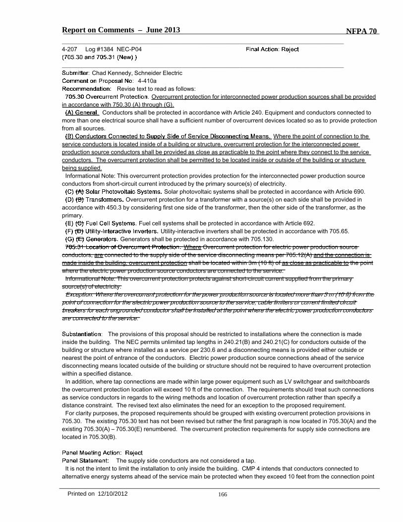
Report on Comments – June 2013 NFPA 70_______________________________________________________________________________________________4-207 Log #1384 NEC-P04
_______________________________________________________________________________________________Chad Kennedy, Schneider Electric
4-410aRevise text to read as follows:
Overcurrent protection for interconnected power production sources shall be providedin accordance with 750.30 (A) through (G).
Conductors shall be protected in accordance with Article 240. Equipment and conductors connected tomore than one electrical source shall have a sufficient number of overcurrent devices located so as to provide protectionfrom all sources.
Where the point of connection to theservice conductors is located inside of a building or structure, overcurrent protection for the interconnected powerproduction source conductors shall be provided as close as practicable to the point where they connect to the serviceconductors. The overcurrent protection shall be permitted to be located inside or outside of the building or structurebeing supplied.
Informational Note: This overcurrent protection provides protection for the interconnected power production sourceconductors from short-circuit current introduced by the primary source(s) of electricity.
Solar photovoltaic systems shall be protected in accordance with Article 690.Overcurrent protection for a transformer with a source(s) on each side shall be provided in
accordance with 450.3 by considering first one side of the transformer, then the other side of the transformer, as theprimary.
Fuel cell systems shall be protected in accordance with Article 692.Utility-interactive inverters shall be protected in accordance with 705.65.
Generators shall be protected in accordance with 705.130.Where Overcurrent protection for electric power production source
conductors, are connected to the supply side of the service disconnecting means per 705.12(A) and the connection ismade inside the building, overcurrent protection shall be located within 3m (10 ft) of as close as practicable to the pointwhere the electric power production source conductors are connected to the service.
Informational Note: This overcurrent protection protects against short-circuit current supplied from the primarysource(s) of electricity.
The provisions of this proposal should be restricted to installations where the connection is madeinside the building. The NEC permits unlimited tap lengths in 240.21(B) and 240.21(C) for conductors outside of thebuilding or structure where installed as a service per 230.6 and a disconnecting means is provided either outside ornearest the point of entrance of the conductors. Electric power production source connections ahead of the servicedisconnecting means located outside of the building or structure should not be required to have overcurrent protectionwithin a specified distance.
In addition, where tap connections are made within large power equipment such as LV switchgear and switchboardsthe overcurrent protection location will exceed 10 ft of the connection. The requirements should treat such connectionsas service conductors in regards to the wiring methods and location of overcurrent protection rather than specify adistance constraint. The revised text also eliminates the need for an exception to the proposed requirement.
For clarity purposes, the proposed requirements should be grouped with existing overcurrent protection provisions in705.30. The existing 705.30 text has not been revised but rather the first paragraph is now located in 705.30(A) and theexisting 705.30(A) – 705.30(E) renumbered. The overcurrent protection requirements for supply side connections arelocated in 705.30(B).
The supply side conductors are not considered a tap.It is not the intent to limit the installation to only inside the building. CMP 4 intends that conductors connected to
alternative energy systems ahead of the service main be protected when they exceed 10 feet from the connection point
166Printed on 12/10/2012
Report on Comments – June 2013 NFPA 70to limit the effects of fault currents that may be imposed upon them from the service.
_______________________________________________________________________________________________4-208 Log #89 NEC-P04
_______________________________________________________________________________________________Technical Correlating Committee on National Electrical Code®,
4-410aThe Correlating Committee directs this proposal be clarified by replacing "per 705.12(A)" with "in
accordance with 705.12(A)" to conform with 4.1 of the NEC Style Manual.This action will be considered as a public comment.
This is a direction from the National Electrical Code Technical Correlating Committee in accordancewith 3.4.2 and 3.4.3 of the Regulations Governing Committee Projects.
167Printed on 12/10/2012

Report on Comments – June 2013 NFPA 70_______________________________________________________________________________________________4-209 Log #1509 NEC-P04
_______________________________________________________________________________________________William F. Brooks, Brooks Engineering
4-416Revise language as follows:
705.100 Unbalanced Interconnections.(A) Single Phase. Single-phase inverters for hybrid systems and ac modules in interactive hybrid systems shall not beconnected to 3-phase power systems unless the interconnected system is designed so that significant unbalancedvoltages in excess of 3% do not cannot result. For utility-interactive single-phase inverters, unbalanced voltages shall beprevented by the same methods used for single-phase loads on a 3-phase power system.
The code making panel was in error by not accepting proposal 4-416. The reason given was thatsufficient substantiation was not provided. The substantiation was sufficient in that it outlined the problem and how therevised wording addressed the problem. AHJs are routinely misinterpreting this ambiguous language. Since thelanguage is unclear, the common misconception is that the National Electrical Code is prohibiting single-phase inverterson three-phase systems. Since no criteria for acceptance is provided, this overly conservative interpretation is common.The wording in the existing 705.100 violates the style manual, which specifically prohibits unenforceable language suchas is found in 705.100.Quoting from the NEC Style Manual:“3.2 Word Choices.3.2.1 Unenforceable Terms. The NEC shall not contain references or requirements that are unenforceable or vague.The terms contained in Table 3.2.1 shall be reviewed in context, and, if the resulting requirement is unenforceable orvague, the term shall not be used.” …”Significant”.The current language in 705.100(A) is unenforceable by any means other than prohibiting single-phase generators on3-phase power systems altogether. This is due to the undefined nature of the term “significant unbalanced voltages.”This undefined term is replaced with “unbalanced voltages in excess of 3% do not result.” Single phase generators areroutinely applied to 3-phase power systems successfully and without special phase voltage sensing equipment. This isaccomplished with utility-interactive inverters by applying the well-understood methods used for single-phase loads for3-phase systems. Single-phase loads are evenly distributed among the phases unless the single phase loads are notdivisible by 3. In the event that a 3-phase circuit has extra single-phase loads, those loads are applied to the leastloaded phases, therefore reducing imbalance rather than increasing imbalance. With utility-interactive single-phasegenerators, extra single-phase generators are applied to the most heavily loaded phases, reducing imbalance. Manyjurisdictions have been prohibiting the use of single-phase utility-interactive generators on 3-phase systems thinking thatthese inverters had to be capable of sensing all three phases to prohibit imbalance. Since single-phase loads are notrequired to monitor all three phases and imbalance is prevented by design, utility-interactive inverters should follow thesame, well-understood process. The only method to resolve an unbalanced voltage not caused by the utility system is tobalance loads and generation on the building distribution system. Both single-phase load distribution and single-phasegenerator distribution can be effective means of mitigating unbalanced phase currents that contribute to unbalancedvoltages.
Revise the recommended text to read as follows:705.100 Unbalanced Interconnections.(A) Single Phase. Single-phase inverters for hybrid systems and ac modules in interactive hybrid systems shall be
connected to 3-phase power systems in order to limit unbalanced voltages to not more than 3 percent.Informational Note: For utility-interactive single-phase inverters, unbalanced voltages can be minimized by the same
methods that are used for single-phase loads on a 3-phase power system. See ANSI/C84.1 Electric Power Systemsand Equipment - Voltage Calculations.
The panel has moved the last proposed sentence to an informational note. The text was rewordedfor clarity. Additionally reference is made to ANSI/C84.1 as a method of calculation.
168Printed on 12/10/2012
Related Documents