Bicol International Airport Development Project Division 13 – Special Construction Section VI- Technical Specification Lightning Protection System 2 of 3 required for unusual situations shall comply as closely with the conventional system as well as NFC 17-102 (Clause 4.1 to 6.8) 2.5 MAST Provide mast designed for wind loading of 250 kilometers per hour. Mast shall be galvanized steel pipe. PART 3 - EXECUTION 3.1 INSTALLATION Electrical installations shall conform to the requirements of the Philippine Electrical Code, French Standard NFC 17-102 and to the requirements specified herein. 3.2 AIR TERMINAL Install air terminal as per manufacturer’s recommendation. 3.3 DOWN CONDUCTOR Down conductor shall be installed as direct as possible to the ground. Equipment potential grounding with the structure shall be done to prevent occurrence of dangerous side flash. Provide clamps every 1.5 meters to secure the conductor. Install a counter terminal box to record the number of lightning strikes. 3.4 AIR TERMINAL SUPPORT The air terminal support shall include elevation mast made of galvanized steel pipe, mounting bracket, guy wires and accessories as indicated. Mast shall be properly bonded to the down conductor. 3.5 GROUNDING Make ground connections as specified in Division 16301, “Underground Electrical Work”. Where the copper-grounding conductor is connected to a metal other than copper, provide specially treated or lined connectors suitable for this purpose. 3.6 FIELD TESTS The Contractor shall provide all the test equipment and personnel and submit written copies of test results. a. Grounding System Test: Test ground rods for ground resistance before any wire is connected. Take measurements in normal dry weather, not less than 48 hours after rainfall. 4.0 METHOD OF MEASUREMENT Ground wire of the size specified will be measured by the linear meter installed and accepted. Early streamer emission type air terminal, counter terminal box, mounting mast, ground rod, ground bus, ground test well and exothermic welds will be measured by the set installed and accepted. Testing and commissioning will be measured by one (1) lot.

Welcome message from author
This document is posted to help you gain knowledge. Please leave a comment to let me know what you think about it! Share it to your friends and learn new things together.
Transcript
Bicol International Airport Development Project Division 13 – Special Construction Section VI- Technical Specification Lightning Protection System
2 of 3
required for unusual situations shall comply as closely with the conventional system as well as NFC 17-102 (Clause 4.1 to 6.8)
2.5 MAST
Provide mast designed for wind loading of 250 kilometers per hour. Mast shall be galvanized steel pipe.
PART 3 - EXECUTION
3.1 INSTALLATION
Electrical installations shall conform to the requirements of the Philippine Electrical Code, French Standard NFC 17-102 and to the requirements specified herein.
3.2 AIR TERMINAL
Install air terminal as per manufacturer’s recommendation. 3.3 DOWN CONDUCTOR
Down conductor shall be installed as direct as possible to the ground. Equipment potential grounding with the structure shall be done to prevent occurrence of dangerous side flash. Provide clamps every 1.5 meters to secure the conductor. Install a counter terminal box to record the number of lightning strikes.
3.4 AIR TERMINAL SUPPORT
The air terminal support shall include elevation mast made of galvanized steel pipe, mounting bracket, guy wires and accessories as indicated. Mast shall be properly bonded to the down conductor.
3.5 GROUNDING
Make ground connections as specified in Division 16301, “Underground Electrical Work”. Where the copper-grounding conductor is connected to a metal other than copper, provide specially treated or lined connectors suitable for this purpose.
3.6 FIELD TESTS
The Contractor shall provide all the test equipment and personnel and submit written copies of test results.
a. Grounding System Test: Test ground rods for ground resistance before any wire is
connected. Take measurements in normal dry weather, not less than 48 hours after rainfall.
4.0 METHOD OF MEASUREMENT
Ground wire of the size specified will be measured by the linear meter installed and accepted. Early streamer emission type air terminal, counter terminal box, mounting mast, ground rod, ground bus, ground test well and exothermic welds will be measured by the set installed and accepted.
Testing and commissioning will be measured by one (1) lot.
Bicol International Airport Development Project Division 13 – Special Construction Section VI- Technical Specification Lightning Protection System
3 of 3
5.0 BASIS OF PAYMENT
The quantities accepted as provided in Method of Measurement, shall be paid for at the contract unit price per unit of measurement for each of the Pay Items listed below and shown in the Bill of Quantities, which price and payment shall be full compensation for furnishing and placing all materials, including all labor, equipment, tools and incidentals necessary to complete the work prescribed in this Section.
Payment will be made in accordance with the Bill of Quantities.
******
Bicol International Airport Development Project Division 13 – Special Construction Section VI- Technical Specifications Fire Pumps
1 of 12
SECTION 13920 - FIRE PUMPS
PART 1 - GENERAL
1.1 REFERENCES
The publications listed below form a part of this specification to the extent referenced. The publications are referred to in the text by basic designation only.
1.1.1 American Society for Testing and Materials (ASTM):
ASTM A 183 (1998) Carbon Steel Bolts and Nuts ASTM A 194 (2001) Carbon and Alloy Steel Nuts for Bolts
/A 194 M for High-Pressure or High-Temperature Service or Both
ASTM A 449 (2000) Quenched and Tempered Steel Bolts and Studs
ASTM A 53/A 53 M (2001) Pipe, Steel, Black and Hot-Dipped, Zinc-
Coated, Welded and Seamless ASTM A 563 (2000) Carbon and Alloy 1.1.2 American Water Works Association (AWWA) Publications:
AWWA C110 (1998) Ductile-Iron and Gray-Iron Fittings, 3 In. Through 48 In. (75 mm through 1200 mm), for Water and Other Liquids
AWWA C651 Disinfecting Water Mains
AWWA C606 Groove and shouldered joints AWWA D500 Gate valves, 3 through 48 in NPS, for Water and Sewage System
1.1.3 American Society of Mechanical Engineers (ASME) Publications: ASME B16.3 (1998) Malleable Iron Threaded Fittings
ASME B16.39 (1998) Malleable Iron Threaded Pipe Unions Classes 150, 250, and
300
ASME B16.5 (1996; B16.5a) Pipe Flanges and Flanged Fittings NPS 1/2 thru NPS 24
ASME B16.9 (1993) Factory-Made Wrought Steel Butt welding Fittings
1.1.4 Factory Mutual Engineering and Research (FM)
FM P7825a (1998) Approval Guide Fire Protection
FM P7825b (1998) Approval Guide Electrical Equipment
1.1.5 Manufacturers Standardization Society of the Valve and Fittings
Industry (MSS)
MSS SP-80 (1997) Bronze Gate, Globe, Angle and Check Valves
Bicol International Airport Development Project Division 13 – Special Construction Section VI- Technical Specifications Fire Pumps
2 of 12
1.1.6 NATIONAL ELECTRICAL MANUFACTURERS ASSOCIATION (NEMA)
MG 1 (1998) Motors and Generators
1.1.6 National Fire Protection Association (NFPA) Publication:
NFPA 20 Installation of Stationary Pump for Fire Protection
NFPA 24 Installations of Private Service Main and Appurtenances
NFPA 70 National Electrical Code
1.1.7 Underwriters Laboratories (UL)
UL 262 Gates Valves for Fire Protection Service UL 448 Pumps for Fire Protection Service
1.2 GENERAL REQUIREMENTS
Except as modified in this Section or on the drawings, fire pumps shall be installed in conformance with NFPA 20, including all recommendations and advisory portions, which shall be considered mandatory. All reference to the authority having jurisdiction shall be interpreted to mean the Project.
1.3 SEQUENCE OF OPERATION
1.3.1 Pressure Maintenance Pump (Jockey Pump)
Jockey Pump shall automatically operate when the pressure drops to 10 PSI of the system pressure. The jockey pump shall automatically stop operating when the system pressure is reached.
1.3.2 Primary Fire Pump
Fire pump shall operate 5 PSI less than the jockey pump start point. The fire pump shall be manually stopped.
1.3.3 Safety Requirements
Coupling, rotating parts, gears, projecting equipment, etc. shall be fully enclosed or properly guarded so as to prevent possible injury to persons that come in close proximity of the equipment. The Contractor shall conduct testing of the fire pumps in a safe manner and ensure that all equipment is safely secured. Hoses and nozzles used to conduct flow tests shall be in excellent condition and shall be safely anchored and secured to prevent any misdirection of the hose streams.
1.4 COORDINATION OF TRADES
Tank supports, piping offsets, fittings, and any other accessories required shall be furnished as specified to provide a complete installation and to eliminate interference with other construction.
1.5 DELIVERY AND STORAGE
All equipment delivered and placed in storage shall be housed with protection from the weather, excessive humidity and temperature variations, dirt and dust, or other contaminants. Additionally, all pipes shall be either capped or plugged until installed.
Bicol International Airport Development Project Division 13 – Special Construction Section VI- Technical Specifications Fire Pumps
3 of 12
1.6 FIELD MEASUREMENTS
After becoming familiar with all details of the work, the Contractor shall verify all dimensions in the field, and shall advise the Engineer of any discrepancy before performing the work.
1.7 SUBMITTALS 1.7.1 Shop Drawings
Fire Pump Installation Drawings consisting of a detailed plan view, detailed elevations and sections of the pump room, equipment and piping, drawn to a scale of not less than 1: 50 meters. Drawings shall indicate equipment, piping, and associated pump equipment to scale. All clearance, such as those between piping and equipment; between equipment and walls, ceiling and floors; and for electrical working distance clearance around all electrical equipment shall be indicated. Drawings shall include a legend identifying all symbols, nomenclatures, and abbreviations. Drawings shall indicate a complete piping and equipment layout including elevations and/or section views of the following:
a. Fire pumps, controller, piping, valves, and associated equipment.
b. Sensing line for the pump including the pressure maintenance pump.
c. Pipe hangers and sway bracing.
d. A one-line schematic diagram indicating layout and sizes of all piping, devices, valves and fittings.
e. A complete point-to-point connection drawing of the pump power, control and alarm
systems, as well as interior wiring schematic of each controller.
1.7.2 As-Built Drawings
As-built drawings shall be submitted not later than 14 days after completion of the Final Tests. The Fire Pump Installation Drawings shall be updated to reflect as-built conditions after all related work is completed and shall be on reproducible full-size mylar film.
1.7.3 Product Data:
a. Fire Pump
b. Jockey Pump
c. Fire pump controller
d. Jockey pump controller
e. Pipes, fittings, and mechanical couplings
f. Valves, including gate, check, globe and relief valves
g. Gauges
h. Hose valve manifold test header and hose valves.
i. Flow meter
j. Restrictive orifice union
k. Associated devices and equipment
1.7.4 Preliminary Test Procedures
a. Proposed procedures for Preliminary Tests shall be submitted at least 14 days prior
to the proposed start of the tests.
Bicol International Airport Development Project Division 13 – Special Construction Section VI- Technical Specifications Fire Pumps
4 of 12
b. Proposed date and time to begin Preliminary Tests, submitted with the preliminary Tests Procedures.
1.7.5 Field Training
Proposed schedule for field training submitted at least 14 days prior to the start of related training.
1.7.6 Test Reports
a. Preliminary Test
Submit three (3) copies of the completed Preliminary Tests Reports, no later than 7 days after the completion of the Preliminary Tests. The Preliminary Tests Report shall include both the Contractor's Material and Test Certificate for Underground Piping and the Contractor's Material and Test Certificate for Aboveground Piping and in accordance to testing procedure stated in NFPA 20. All items in the Preliminary Tests Report shall be signed by the Fire Protection Specialist and the Manufacturer's Representative.
b. Final Acceptance Test
Three (3) copies of the completed Final Acceptance Tests Reports , no later that 7 days after the completion of the Final Acceptance Tests. All items in the Final Acceptance Report shall be signed by the Fire Protection Specialist and the Manufacturer's Representative. Test reports in booklet form each copy furnished in a properly labeled three ring binder showing all field tests and measurements taken during the preliminary and final testing, and documentation that proves compliance with the specified performance criteria, upon completion of the installation and final testing of the installed system. Each test report shall indicate the final position of the controls and pressure switches. The test reports shall include the description of the hydrostatic test conducted on the piping and flushing of the suction and discharge piping. A copy of the manufacturer's certified pump curve for each fire pump shall be included in the report.
1.7.7 Certificates 1.7.8 Operation and Maintenance Data
Six (6) manuals listing step-by-step procedures required for system startup, operation, shutdown, and routine maintenance, at least 14 days prior to field training. The manuals shall include the manufacturer's name, model number, parts list, list of parts and tools that should be kept in stock by the owner for routine maintenance including the name of a local supplier, simplified wiring and controls diagrams, troubleshooting guide, and recommended service organization (including address and telephone number) for each item of equipment. Each service organization submitted shall be capable of providing 4 hour onsite response to a service call on an emergency basis.
1.8 FIRE PROTECTION SPECIALIST
Work specified in this section shall be performed under the supervision of and certified by the Fire Protection Specialist. The Fire Protection Specialist shall be an individual who is a registered professional engineer and the Fire Protection Specialist shall be regularly engaged in the design and installation of the type and complexity of system specified in the Contract documents, and shall have served in a similar capacity for at least three systems that have performed in the manner intended for a period of not less than 6 months.
Bicol International Airport Development Project Division 13 – Special Construction Section VI- Technical Specifications Fire Pumps
5 of 12
1.9 MANUFACTURER’S REPRESENTATIVE
Work specified in this section shall be performed under the supervision of and certified by a representative of the fire pump manufacturer. The Manufacturer's Representative shall be regularly engaged in the installation of the type and complexity of fire pump(s) specified in the Contract documents, and shall have served in a similar capacity for at least three systems that have performed in the manner intended for a period of not less than 6 months.
1.10 REGULATORY REQUIREMENTS
Compliance with referenced NFPA standards is mandatory. This includes advisory provisions listed in the appendices of such standards, as though the word "shall" had been substituted for the word "should" wherever it appears. In the event of a conflict between specific provisions of this specification and applicable NFPA standards, this specification shall govern. Reference to "authority having jurisdiction" shall be interpreted to mean the Engineer.
PART 2 - PRODUCTS
2.1 STANDARD PRODUCTS
Materials and equipment shall be standard products of a manufacturer regularly engaged in the manufacture of such products and shall essentially duplicate items that have been in satisfactory use for at least 2 years prior to bid opening.
2.2 NAMEPLATES
All equipment shall have a nameplate that identifies the manufacturer's name, address, type or style, model or serial number, and catalog number. Pumps and motors shall have standard nameplates securely affixed in a conspicuous place and easy to read. Fire pump shall have nameplates and markings in accordance with UL 448. Electric motor nameplates shall provide the minimum information required by NFPA 70, Section 430-7.
2.3 REQUIREMENTS FOR FIRE PROTECTION SERVICE
Materials and Equipment shall have been tested by Underwriters Laboratories, Inc. and listed in UL Fire Prot Dir or approved by Factory Mutual. Where the terms "listed" or "approved" appear in this specification, such shall mean listed in UL.
2.4 UNDERGROUND PIPING COMPONENTS 2.4.1 Pipe and Fittings
Underground piping and piping under the building slab shall be BI schedule 40 with corrosion protection. Piping more than 1500 mm (5 feet) outside the building walls shall comply with appropriate section.
2.4.2 Fittings and Gaskets
Fittings shall be ductile iron conforming to AWWA C110. Gaskets shall be suitable in design and size for the pipe with which such gaskets are to be used. Gaskets for steel pipe joints shall conform to AWWA C111.
2.4.3 Valves and Valve Boxes
Valves shall be gate valves conforming to AWWA C500 or UL 262. Valves shall have cast-iron body and bronze trim. Valve shall open by counterclockwise rotation. Except for post indicator valves, all underground valves shall be provided with an adjustable cast-iron or ductile iron valve box of a size suitable for the valve on which the box is to be used, but not less than 133 mm (5.25 inches) in diameter. The box shall be coated with bituminous coating. A cast-iron or ductile-iron cover with the word "WATER" cast on the cover shall be provided
Bicol International Airport Development Project Division 13 – Special Construction Section VI- Technical Specifications Fire Pumps
6 of 12
for each box. 2.4.4 Gate Valve and Indicator Posts
Gate valves for underground installation shall be of the inside screw type with counterclockwise rotation to open. Where indicating type valves are shown or required, indicating valves shall be gate valves with an approved indicator post of a length to permit the top of the post to be located 900 mm (3 feet) above finished grade. Gate valves and indicator posts shall be listed in UL or FM approved
2.5 TAMPER SWITCH
The suction control valves, the discharge control valves, valves to test header and flow meter, and the by-pass control valves shall be equipped with valve tamper switches for monitoring by the fire alarm system.
2.5.1 Check Valve
Check valve shall be clear open, swing type check valve with flange or threaded inspection plate.
2.5.2 Relief Valve
Relief valve shall be spring operated type conforming to NFPA 20. A means of detecting water motion in the relief lines shall be provided where the discharge is not visible within the fire pump house.
2.5.3 Circulating Relief Valve
An adjustable circulating relief valve shall be provided for each fire pump in accordance with NFPA 20.
2.5.4 Suction Pressure Regulating Valve
Suction pressure regulating valve shall be FM approved FM P7825a and FM P7825b. Suction pressure shall be monitored through a pressure line to the controlling mechanism of the regulating valve. Valve shall be arranged in accordance with the manufacturer's recommendations.
2.6 FIRE PUMP
Fire pump shall be electric motor driven. Pump capacity shall be rated as shown on the drawing at liters per second (GPM) with a rated net pressure of meters (PSI) as indicated on the equipment schedule. Fire pump shall furnish not less than 150 percent of rated flow capacity at not less than 65 percent of rated net pressure. Pump shall be centrifugal horizontal split case fire pump. Horizontal pump shall be equipped with automatic air release devices. The maximum rated pump speed shall be 1750 rpm when driving the pump at rated capacity. Pump shall conform to the requirements of UL 448 and FM approved. Fire pump discharge and suction gauges shall be oil-filled type.
2.7 ELECTRIC MOTOR DRIVER
Motor shall conform to NEMA MG 1 and be marked as complying with NEMA Design B standards. Motor wattage (horsepower) shall be of sufficient size so that the nameplate wattage (horsepower) rating will not be exceeded throughout the entire published pump characteristic curve. The motor and fire pump controller shall be fully compatible.
2.8 FIRE PUMP CONTROLLER
Controller shall be the automatic type and UL listed and FM approved for fire pump service.
Bicol International Airport Development Project Division 13 – Special Construction Section VI- Technical Specifications Fire Pumps
7 of 12
Pump shall be arranged for automatic start and manual push-button stop. Controllers shall be completely terminally wired, ready for field connections, and mounted in a NEMA Type 4 watertight and dust tight enclosure arranged so that controller current carrying parts will not be less than 300 mm (12 inches) above the floor. Controller shall be provided with voltage surge arresters installed per NFPA 20. Controller shall be equipped with a bourdon tube pressure switch or a solid state pressure switch with independent high and low adjustments, automatic starting relay actuated from normally closed contacts, visual alarm lamps and supervisory power light.
2.8.1 Controller for Electric Motor Driven Fire Pump
Controller shall be wye-delta, open circuit starting type. Controller shall be designed for as indicated. An automatic transfer switch (ATS) shall be provided for each fire pump. The ATS shall comply with NFPA 20 and shall be specifically listed for fire pump service. The ATS shall transfer source of power to the alternate source upon loss of normal power. Controller shall monitor pump running, loss of a phase or line power, phase reversal, low reservoir water and pump room temperature. Alarms shall be individually displayed in front of panel by lighting of visual lamps. Each lamp shall be labeled with rigid etched plastic labels.
Controller shall be equipped with terminals for remote monitoring of pump running, pump power supply trouble, loss of power or phase and phase reversal, and pump room trouble, pump room temperature and low reservoir level. Limited service fire pump controllers are not permitted, except for fire pumps driven by electric motors rated less than 11 kW (15 hp). Controller shall be equipped with a 7-day electric pressure recorder with 24-hour spring wound back-up. The pressure recorder shall provide a read out of the system pressure from 0 to 207 Pa (0 to 15 hp), time, and date. Controller shall require the pumps to run for ten minutes for pumps with driver motors under 149 kW (200 horsepower) and for 15 minutes for pumps with motors 149 kW (200 horsepower) and greater, prior to automatic shutdown. The controller shall be equipped with an externally operable isolating switch which manually operates the motor circuit. Means shall be provided in the controller for measuring current for all motor circuit conductors.
2.9 PRESSURE SENSING LINE A completely separate pressure sensing line shall be provided for each fire pump and for the jockey pump. The sensing line shall be arranged in accordance with Figure A-7-5.2.1. of NFPA 20. The sensing line shall be 15 mm (1/2 inch) H58 brass tubing complying with ASTM B 135MASTM B 135. The sensing line shall be equipped with two restrictive orifice unions each. Restricted orifice unions shall be ground-face unions with brass restricted diaphragms drilled for a 2.4 mm (3/32 inch). Restricted orifice unions shall be mounted in the horizontal position, not less than 1.5 m (5 feet) apart on the sensing line. Two test connections shall be provided for each sensing line. Test connections shall consist of two brass 15 mm (1/2 inch) globe valves and 8 mm (1/4 inch) gauge connection tee arranged per NFPA 20. One of the test connections shall be equipped with a 0 to 1380 kPa (0 to 300 psi) water oil-filled gauge. Sensing line shall be connected to the pump discharge piping between the discharge piping control valve and the check valve.
2.10 PRESSURE MAINTENANCE PUMP (JOCKEY PUMP)
Pressure maintenance pump shall be electric motor driven in-line vertical shaft, centrifugal type with a rated discharge as indicated on the drawing. Pump shall draft as indicated and shall discharge into the system at the downstream side of the pump discharge gate valve. An approved indicating gate valve of the outside screw and yoke (O.S.&Y.) type shall be provided in the maintenance pump discharge and suction piping. Oil-filled water pressure gauge and approved check valve in the maintenance pump discharge piping shall be provided. Check valve shall be swing type with removable inspection plate.
a. Pressure Maintenance Pump Controller
Pressure maintenance pump controller shall be arranged for automatic and manual
Bicol International Airport Development Project Division 13 – Special Construction Section VI- Technical Specifications Fire Pumps
8 of 12
starting and stopping and equipped with a "manual-off-automatic" switch. The controller shall be completely pre-wired, ready for field connections, and wall-mounted in a NEMA Type 2 drip-proof enclosure. The controller shall be equipped with a bourdon tube pressure switch or a solid state pressure switch with independent high and low adjustments for automatic starting and stopping. A sensing line shall be provided connected to the pressure maintenance pump discharge piping between the control valve and the check valve. The sensing line shall conform to paragraph 2.9, Pressure Sensing Line. The sensing line shall be completely separate from the fire pump sensing lines. An adjustable run timer shall be provided to prevent frequent starting and stopping of the pump motor. The run timer shall be set for 2 minutes.
2.11 PUMP BASE PLATE AND PAD
A common base plate shall be provided for each horizontal-shaft fire pump for mounting pump and driver unit. The base plate shall be constructed of cast iron with raised lip tapped for drainage or welded steel shapes with suitable drainage. Each base plate for the horizontal fire pumps shall be provided with a 25 mm (1 inch) galvanized steel drain line piped to the nearest floor drain. For vertical shaft pumps, pump head shall be provided with a cast-iron base plate and shall serve as the sole plate for mounting the discharge head assembly. Pump units and bases shall be mounted on a raised 150 mm (6 inches) reinforced concrete pad that is an integral part of the reinforced concrete floor.
2.12 FLOW METER
Meter shall be UL listed and FM approved flow meters for fire pump installation with direct flow readout device. Flow meter shall be capable of metering any water flow quantities between 50 percent and 150 percent of the rated flow of the pumps. The flow meter shall be arranged in accordance with Figure A-2-14.2.1 of NFPA 20.The meter throttle valve and the meter control valves shall be O.S.&Y. valves. Automatic air release shall be provided if flow meter test discharge is piped to the pump suction and forms a closed-loop meter arrangement as defined in Figure A-2-14.2.1 of NFPA 20.
2.13 PIPE SLEEVE
A pipe sleeve shall be provided at each location where piping passes through walls, ceilings, roofs, and floors, including pipe entering buildings from the exterior. Sleeves shall be grouted in position during construction. Sleeve shall be of sufficient length to pass through the entire thickness of the wall, ceilings, roofs and floors. The space between the exterior surface of the pipe and the interior surface of the sleeve shall be firmly packed with mineral wool insulation and caulk at both ends with plastic waterproof cement which will dry to a firm but pliable mass, or with a segmented electrometric seal. Where pipes pass through fire walls or fire floors, a fire seal shall be provided between the pipe and the sleeve. Sleeves in masonry and concrete walls, ceiling, roofs and floors shall be hot-dip galvanized steel, ductile-iron, or cast-iron. Other sleeves shall be galvanized steel sheet pipe not less than 4.4 kg per square meter (0.90 psf).
2.14 ESCUTCHEON (WALL) PLATES
Escutcheon plates shall be one-piece or split-hinge type metal plates and shall be provided for piping passing through floors, walls, and ceiling in exposed areas. In finished areas, plates shall be polished stainless steel or chromium-plated finish on copper alloy. In unfinished areas, plates shall have painted finish. Plates shall be secured in position.
2.15 DISINFECTING MATERIALS
a. Liquid Chlorine
Liquid chlorine shall conform to AWWA B301.
Bicol International Airport Development Project Division 13 – Special Construction Section VI- Technical Specifications Fire Pumps
9 of 12
b. Hypochlorite
Calcium hypochlorite and sodium hypochlorite shall conform to AWWA B300.
PART 3 - EXECUTION
3.1 INSPECTION BY FIRE PROTECTION SPECIALIST
The Fire Protection Specialist shall inspect the fire pump installation periodically to assure that the installation conforms to the contract requirements. The Fire Protection Specialist shall perform a thorough inspection of the fire pump installation, including visual observation of the pump while running shall be conducted. There shall be no excessive vibration, leaks (oil or water), unusual noises, overheating, or other potential problems. Inspection shall include piping and equipment clearance, access, supports, and guards. Any discrepancy shall be brought to the attention of the Engineer in writing, no later than three working days after the discrepancy is discovered. The Fire Protection Specialist shall witness the preliminary and final acceptance tests and, after completion of the inspections and a successful final acceptance test, shall sign test results and certify in writing that the installation of the fire pump is in accordance with the contract requirements.
3.2 INSTALLATION REQUIREMENTS
Installation, workmanship, fabrication, assembly, erection, examination, inspection and testing shall be in accordance to NFPA 20, except as modified herein. In addition, the fire pump and motor shall be installed in accordance with the written instructions of the manufacturer.
3.3 PIPE AND FITTINGS
Piping shall be inspected, tested and approved before burying, covering, or concealing. Fittings shall be provided for changes in direction of piping and for all connections. Changes in piping sizes shall be made using tapered reducing pipe fittings. Bushings shall not be used.
3.3.1 Cleaning of Piping
Interior and ends of piping shall be clean and free of any water or foreign material. Piping shall be kept clean during installation by means of plugs or other approved methods. When work is not in progress, open ends of the piping shall be securely closed so that no water or foreign matter will enter the pipes or fittings. Piping shall be inspected before placing in position.
3.3.2 Threaded Connections
Jointing compound for pipe threads shall be polytetrafluoroethylene (PTFE) pipe thread tape conforming to ASTM D 3308 and shall be applied to male threads only. Exposed ferrous pipe threads shall be provided with one coat of zinc molybdate primer applied to a minimum of dry film thickness of 0.025 mm 1 ml.
3.3.3 Pipe Hangers and Supports
Additional hangers and supports shall be provided for concentrated loads in aboveground piping, such as for valves and risers.
a. Vertical Piping
Piping shall be supported at each floor, at not more than 3 meters (10 foot) intervals.
b. Horizontal Piping
Horizontal piping supports shall conform to NFPA 13.
Bicol International Airport Development Project Division 13 – Special Construction Section VI- Technical Specifications Fire Pumps
10 of 12
3.3.4 Underground Piping
Installation of underground piping and fittings shall conform to NFPA 24. Joints shall be anchored in accordance with NFPA 24. Concrete thrust block shall be provided at elbow where pipe turns up towards floor, and the pipe riser shall be restrained with steel rods from the elbow to the flange above the floor. After installation per NFPA 24, rods and nuts shall be thoroughly cleaned and coated with asphalt or other corrosion-retard material approved by the Engineer. Minimum depth of cover shall be 900 mm (3 feet.)
3.3.5 Grooved Mechanical Joint
Grooves shall be prepared according to the coupling manufacturer's instructions. Grooved fittings, couplings, and grooving tools shall be products of the same manufacturer. Pipe and groove dimensions shall comply with the tolerances specified by the coupling manufacturer. The diameter of grooves made in the field shall be measured using a "go/no-go" gauge, vernier or dial caliper, narrow-land micrometer, or other method specifically approved by the coupling manufacturer for the intended application. Groove width and dimension of groove from end of pipe shall be measured for each change in grooving tool setup to verify compliance with coupling manufacturer's tolerances. Grooved joints shall not be used in concealed locations, such as behind solid walls or ceilings, unless an access panel is shown on the drawings for servicing or adjusting the joint.
3.4 ELECTRICAL WORK
Electric motor and controls shall be in accordance with NFPA 20 and NFPA 70, unless more stringent requirements are specified herein or are indicated on the drawings. Electrical wiring and associated equipment shall be provided in accordance with NFPA 20 and Section 16402, Interior Wiring System.
3.5 PIPE COLOR CODE MARKING
Color code marking of piping shall conform to PMC or other related standards.
3.6 FLUSHING
The fire pump suction and discharge piping shall be flushed at 120 percent of rated capacity of each pump. Where the pump installation consists of more than one pump, the flushing shall be the total quantity of water flowing when all pumps are discharging at 120 percent of their rated capacities. The new pumps may be used to attain the required flushing volume. Flushing operations shall continue until water is clear, but not less than 10 minutes. The Contractor shall submit a signed and dated flushing certificate before requesting field testing.
3.7 FIELD TESTS 3.7.1 Hydrostatic Test
Piping shall be hydrostatically tested at 1379 kPa (200 psig) for a period of 2-hours, or at least 345 kPa (50 psig) excess of the maximum pressure, when the maximum pressure in the system is in excess of 1207 kPa (175 psi).
3.7.2 Preliminary Test
The Fire Protection Specialist shall take all readings and measurements. The Manufacturer's Representative, a representative of the fire pump controller manufacturer, shall witness the complete operational testing of the fire pump and drivers. The fire pump controller manufacturer's representative shall each be an experienced technician employed by the respective manufacturers and capable of demonstrating operation of all features of respective
Bicol International Airport Development Project Division 13 – Special Construction Section VI- Technical Specifications Fire Pumps
11 of 12
components including trouble alarms and operating features. Fire pumps, drivers and equipment shall be thoroughly inspected and tested to insure that the system is correct, complete, and ready for operation. Tests shall ensure that pumps are operating at rated capacity, pressure and speed. Tests shall include manual starting and running to ensure proper operation and to detect leakage or other abnormal conditions, flow testing, automatic start testing, testing of automatic settings, sequence of operation check, test of required accessories; test of pump alarms devices and supervisory signals, test of pump cooling, operational test of relief valves, and test of automatic power transfer, if provided. Pumps shall run without abnormal noise, vibration or heating. If any component or system was found to be defective, inoperative, or not in compliance with the contract requirements during the tests and inspection, the corrections shall be made and the entire preliminary test shall be repeated.
3.7.3 Final Acceptance Test
The Fire Protection Specialist shall take all readings and measurements. The Manufacturer's Representative, the fire pump controller manufacturer's representative shall also witness for the final tests. The Contractor shall be responsible for repairing any damage caused by hose streams or other aspects of the test. The final acceptance test shall include the following:
a. Flow Tests
Flow tests using the test header, hoses and play pipe nozzles shall be conducted. Flow tests shall be performed at churn (no flow), 75, 100, 125 and 150 percent capacity for each pump and at full capacity of the pump installation. Flow readings shall be taken from each nozzle by means of a calibrated pitot tube with gauge or other approved measuring equipment. Rpm, suction pressure and discharge pressure reading shall be taken as part of each flow test. Voltage and ampere readings shall be taken on each phase as part of each flow test for electric-motor driven pumps.
b. Starting Tests
Pumps shall be tested for automatic starting and sequential starting. Setting of the pressure switches shall be tested when pumps are operated by pressure drop. Tests may be performed by operating the test connection on the pressure sensing lines. As a minimum, each pump shall be started automatically 10 times and manually 10 times, in accordance with NFPA 20. Tests of engine-driven pumps shall be divided equally between both set of batteries. The fire pumps shall be operated for a period of a least 10 minutes for each of the starts; except that electric motors over 149 kW (200 horsepower) shall be operated for at least 15 minutes and shall not be started more than 2 times in 10 hours. Pressure settings that include automatic starting and stopping of the fire pump(s) shall be indicated on an etched plastic placard, attached to the corresponding pump controller.
c. Miscellaneous
Valve tamper switches shall be tested. Pressure recorder operation relief valve settings, valve operations, operation and accuracy of meters and gauges, and other accessory devices shall be verified.
d. Alternate Power Source
On installations with an alternate source of power and an automatic transfer switch, loss of primary power shall be simulated and transfer shall occur while the pump is operating at peak load. Transfer from normal to emergency source and retransfer from emergency to normal source shall not cause opening of over current devices in either line. At least half of the manual and automatic starting operations listed shall be performed with the fire pump connected to the alternate source.
Bicol International Airport Development Project Division 13 – Special Construction Section VI- Technical Specifications Fire Pumps
12 of 12
3.7.4 Correction of Deficiencies
If equipment was found to be defective or non-compliant with contract requirements, the Contractor shall performed corrective actions and repeat the tests. Tests shall be conducted and repeated if necessary until the system has been demonstrated to comply with all contract requirements.
3.7.5 Test Equipment
The Contractor shall provide all equipment and instruments necessary to conduct a complete final test, including 65 mm (2.5 inch) diameter hoses, play pipe nozzles, pitot tube gauges, portable digital tachometer, voltage and ampere meters, and calibrated oil-filled water pressure gauges. The Contractor shall provide all necessary supports to safely secure hoses and nozzles during the test. The Owner will furnish water for the tests.
3.7.6 Test Documentation
The Manufacturer's Representative shall supply a copy of the manufacturer's certified curve for each fire pump at the time of the test. The Fire Protection Specialist shall record all test results and plot curve of each pump performance during the test. Complete pump acceptance test data of each fire pump shall be recorded. The pump acceptance test data shall be on forms that give the detail pump information such as that which is indicated in Figure A-11-2.6.3(f) of NFPA 20. All test data records shall be submitted in a three ring binder.
3.8 FIELD TRAINING
The Fire Protection Specialist and the Manufacturer's Representative shall conduct a training course for operating and maintenance personnel as designated by the Engineer. Training shall be provided for a period of 8 hours of normal working time and shall start after the fire pump installation is functionally complete but prior to the start tests specified herein. The field instruction shall cover all of the items contained in the approved Operating and Maintenance Instructions.
4.0 METHOD OF MEASUREMENT
Fire pumps, jockey pumps, piping, valves and other piping accessories shall be either counted or measured in linear meters actually installed and accepted to the satisfaction of the Engineer.
5.0 BASIS OF PAYMENT
The quantities determined as provided in Method of Measurement, shall be paid for at the contract unit price, respectively for each Pay Items listed below and shown in the Bill of Quantities which price and payment shall constitute full compensation for furnishing and placing all materials including all labor, equipment, tools and incidentals necessary to complete the work prescribed in this Section.
Payment will be made in accordance with the Bill of Quantities.
******
Bicol International Airport Development Project Division 13 – Special Construction Section VI- Technical Specifications Fire Extinguishing Sprinkler Systems (Wet Pipe)
1 of 7
SECTION 13930 - FIRE EXTINGUISHING SPRINKLER SYSTEMS (WET PIPE) PART 1 - GENERAL 1.1 APPLICABLE PUBLICATIONS
The latest editions of the publications listed below form a part of this specification to the extent referenced. The publications are referred to in the text by the basic designation only.
1.1.1 National Fire Protection Association (NFPA) Publications
NFPA 10 Portable Fire Extinguishers NFPA 13 Installation of Sprinkler Systems NFPA 14 Installation of Standpipe and Hose Systems NFPA 20 Installation of Centrifugal Fire pump NFPA 24 Installation of Private Fire Service Mains and their Appurtenances NFPA 70 National Electrical Code 1.1.2 American Society for Testing and Materials (ASTM) Publications ASTM A 53 Pipe, Steel, Black and Hot-Dipped, Zinc-Coated Welded and Seamless
ASTM A 120 Pipe, Steel, Black and Hot-Dipped Zinc-Coated (Galvanized) Welded and Seamless, for Ordinary Uses
1.1.3 American Water Works Association (AWWA) Publications AWWA D500 Gate Valves, 3 Through 48 in. NPS, for Water and Sewage System AWWA C651 Disinfecting Water Mains 1.1.4 Factory Mutual System (FM) Publication FM Approved Guide (1985) 1.1.5 Underwriters Laboratories Inc. (UL) Publications UL 262 Gate Valves for Fire-Protection Service 1.2 QUALIFICATIONS OF THE INSTALLER
Prior to installation, submit data for approval showing that the Contractor has successfully installed the same type and design of fire extinguishing systems of as specified herein, or that Contractor has a firm contractual agreement with a subcontractor having such required experience. The data shall include the names and locations of at least two establishments where the Contractor or the subcontractor referred to above, has installed such systems. The Contractor shall indicate the type and design of each system and certify that each system has performed satisfactorily in the manner intended for a period of not less than 18 months. The Contractor is required to assign a PME-Professional Mechanical Engineer to prepare hydraulic calculation for fire pump prior to procurement. The PME is required to oversee the overall Fire Pro System’s Installation and Testing & Commissioning (as per RA No. 8495).
1.3 GENERAL REQUIREMENTS
Section 15011, "Mechanical General Requirements", applies to this section, with the additions and modifications specified herein.
1.4 DESCRIPTION OF WORK
Bicol International Airport Development Project Division 13 – Special Construction Section VI- Technical Specifications Fire Extinguishing Sprinkler Systems (Wet Pipe)
2 of 7
The work includes providing the new automatic fire extinguishing sprinkler system to afford complete fire protection coverage throughout the entire area as indicated on the drawing. The equipment, materials, installation, inspection, and testing shall be in strict accordance with the required and advisory provisions of NFPA 10 , 13 and 14, except as modified herein. Each system shall include all materials, accessories, and equipment inside and outside the building to provide each system complete and ready for use. Each system shall be designed to give full consideration to blind spaces, piping, electrical equipment, ductwork, and other construction and equipment in accordance with detailed drawings to be submitted for approval. Locate sprinkler heads in a consistent pattern with ceiling grid, lights, and supply air diffusers. Devices and equipment shall be UL listed or FM approved for use in wet standpipe and hose systems. In the NFPA publications referred to herein, the advisory provisions shall be considered to be mandatory as though the word “shall” had been substituted for “should” wherever it appears.
1.5 SUBMITTALS Partial submittals will not be permitted. Annotate descriptive data to show the specific model, type, and size of each item the Contractor proposes to provide. Prepare working drawings on sheets not smaller than 762 mm x 1067 mm (30 in. x 42 in.), in accordance with the requirements for "Plans and Specifications" as specified in NFPA 14; include data for proper installation of each system. The Design Engineer will review and approve submittals. Before any work is commenced, submit the design, manufacturer's data, and complete sets of working drawings for each system.
1.5.1 Manufacturer's Data a. Pipe, fittings, and mechanical couplings
b. Valves, including gate, check, and globe
c. Sprinkler heads
d. Pipe hangers and supports
e. Fire department connections
f. Portable fire extinguishers
1.5.2 Shop Drawings Fire hose cabinets, sprinkler piping system layout, and portable fire extinguisher mounting. 1.5.3 Operation and Maintenance Manuals a. Alarm check valves
b. Fire Pump/Jockey Pump and associated system controls
1.6 AS-BUILT (RECORD) WORKING DRAWINGS
After completion, but before final acceptance of the work, furnish a complete set of drawings of each system for record purposes. Drawings shall not be smaller than 762 mm x 1067 mm (30 in. x 42 in.) reproducible drawings on tracing paper with title block similar to full size contract drawings. Furnish the as-built (record) working drawings in addition to the as-built contract drawings required by Section 15011, "Mechanical General Requirements".
1.7 ELECTRICAL WORKS
Provide electrical work associated with this section under Section 16402, “Interior Wiring System”, except for control and fire alarm system. Provide fire alarm system under Section 16722,”Interior Fire Alarm System”. Provide control and fire alarm wiring, including connections to fire alarm system under this section in accordance with NFPA 70. Provide wiring in rigid
Bicol International Airport Development Project Division 13 – Special Construction Section VI- Technical Specifications Fire Extinguishing Sprinkler Systems (Wet Pipe)
3 of 7
metal conduit may be used in dry locations not enclosed in concrete or where not subject to mechanical damage.
1.8 FIRE PUMP AND JOCKEY PUMP Provided under Section 13920, Fire Pump. 1.9 EXCAVATION, BACKFILLING, AND COMPACTING Provided under Section 02225 “Excavation, Backfilling, and Compacting Utilities” PART 2 – PRODUCTS 2.1 SPRINKLER HEADS
Heads shall have nominal 15-mm (½-in.) orifice. Release element of each head shall be a thermo-sensitive glass bulb with an Ordinary (57-77°C / 135-170°F) temperature rating. Provide polished chrome ceiling plates and chromium-plated pendent sprinklers below suspended ceilings. For spaces without suspended ceilings, upright sprinklers shall be brass finished. Sidewall sprinklers shall be chrome plated. Sprinklers shall be UL listed and FM approved. Sprinklers shall have their temperature ratings stamped on their deflectors. Types of Sprinkler Heads: Offices/Arrival/Departure 1/2” orifice, 155 ºF, quick response, Hall & Lounges areas 0.20 gpm/sf; k = 5.6
2.2 SPRINKLER CABINETS
Provide a metal cabinet to contain extra sprinkler heads of the types and temperature ratings installed. The cabinet shall also contain a sprinkler head wrench to be used in the removal and installation of spare sprinklers. The number of extra sprinkler heads shall be as specified in NFPA 13.
2.3 ALARM CHECK VALVES
Provide variable pressure type alarm valve complete with retarding chamber, alarm test valve, alarm shutoff valve, drain valve, pressure switch, pressure gauges, accessories, and appurtenances for the proper operation of the system.
2.4 WATER MOTOR ALARMS
Provide alarms of the approved weatherproof and guarded type, to sound locally on the flow of water in each corresponding sprinkler system.
2.5 PRESSURE SWITCHES
Provide switch with circuit opener or closer for the automatic transmittal of an alarm over the facility fire alarm system. Alarm actuating device shall have mechanical diaphragm controlled retard device adjustable from 10 to 150 psi (68.5 to 685 kPa) and shall instantly recycle.
2.6 ABOVE GROUND PIPE AND FITTINGS
Steel piping shall be Schedule 40, ERW, ANSI / ASTM 53. Fittings into which sprinkler heads, sprinkler head riser nipples, or drop nipples are connected shall be welded, threaded, or grooved-end type. Rubber gasketed grooved-end pipe and fittings with mechanical couplings
Bicol International Airport Development Project Division 13 – Special Construction Section VI- Technical Specifications Fire Extinguishing Sprinkler Systems (Wet Pipe)
4 of 7
shall be permitted in pipe sizes 40 mm (1½ in.) and larger. Fittings shall be UL listed or FM approved for use in wet standpipe and hose systems. Fittings, mechanical couplings, and rubber gaskets shall be supplied by the same manufacturer.
2.6.1 Pipe Hangers and Supports Provide in accordance with NFPA 13 and SEISMIC REQUIREMENTS. 2.6.2 Valves
Provide valves UL listed and FM approved for fire service in accordance with NFPA 13. Valves shall be rated for working pressures not less than the maximum pressure to be developed at that point in the system under any condition including the pressure when a permanently installed fire pump is operating at shut-off. Gate valves shall open by counterclockwise rotation. Provide an OS&Y valve beneath each alarm valve in each riser. Check valves shall be flanged, clear-opening, swing-check type with flanged inspection and access cover plate.
2.7 FIRE DEPARTMENT CONNECTIONS
Cast brass, UL listed and FM approved Siamese type connections with two internal-thread pin lug swivel fittings, at least one of which shall have the 2.5-7.5 NH standard thread, as specified in NFPA 1963. Branding: AUTO SPKR / STANDPIPE. Hose connections shall be equipped with listed caps and zinc-coated steel chains.
2.8 TEFLON TAPE
Shall be applied to join threaded connections. Except for equivalent pipe joint compounds, no substitutes shall be allowed.
2.9 ESCUTCHEON PLATES
Provide two-pieces or split-hinge type metal plates for piping passing through walls and floors in exposed spaces. Provide polished stainless steel plates. Secure plates in proper position. Sprinkler and escutcheon plates shall be from the same manufacturer and shall be in polished chrome finish.
2.10 FIRE HOSE CABINET ASSEMBLY
Type II; provide surface mounted fire hose cabinets in accordance with NFPA 14. Cabinet shall be galvanized steel with red enamel finish and clear front panel with cylinder lock. Each cabinet shall be able to contain and shall be provided with an angle valve, a 30 m x 65 mm dia. (100 ft. x 1½ in. dia.) fire hose on non-jam vertical pin type hose rack, Fire Axe, Wrench and one 10 B:C carbon dioxide extinguisher (UL rated) portable fire extinguisher. The cabinet shall be conspicuously identified.
a. Fire Hose
Single-jacketed construction meeting NFPA 1961. Fabric shall be chemical, oil, and rot-proof; resistant to ozone and aging. Fitted with a fog nozzle with protective bumper.
2.11 PORTABLE FIRE EXTINGUISHERS Portable fire extinguishers shall be UL listed or labeled, suitable for intended purpose. 2.12 INSPECTOR’S TEST CONNECTION
Provide test connections approximately 1.8 meters (6 feet) above the floor for each sprinkler system. Provide test connection piping to a location where the discharge will be readily visible and where water may be discharge without property damage.
Bicol International Airport Development Project Division 13 – Special Construction Section VI- Technical Specifications Fire Extinguishing Sprinkler Systems (Wet Pipe)
5 of 7
PART 3 - EXECUTION 3.1 INSTALLATION
Equipment, materials, installation, workmanship, examination, inspection, and testing shall be in accordance with NFPA 13, except as modified herein. Inspect interior of piping before placing into position. Install piping straight and true to bear evenly on hangers and supports. Keep the interior and ends of new piping and existing piping affected by Contractor's operations thoroughly cleaned of water and foreign matter. All openings in the pipeline shall be closed with watertight plugs when pipe laying is stopped at the close of the day’s work or for other reasons, such as rest breaks or meal periods. Anchor joints in accordance with NFPA 24. Provide concrete thrust block at the elbow where the pipe turns up toward the floor, and restrain the pipe riser with steel rods from the elbow to the flange above the floor. Minimum depth of cover shall be 0.9 m (3 ft) at finish grade. Piping outside of the building wall shall be provided under Section 02713, "Exterior Water Distribution System".
3.1.1 Sprinkler head layout in suspended ceilings shall be fully coordinated with the actual layout of ceiling fixtures (e.g., lighting fixtures, air distribution accessories, smoke detectors, ceiling speakers, and smoke detectors). Adjustments shall be made accordingly to avoid any interference of various installations.
3.1.2 Alarm valve with post indicator valve (PIV) shall not be provided with OS&Y valve. 3.1.3 Locate the water motor alarm on the production area wall as close as practical to the water flow
detecting device. The location must be easily accessible for cleaning.
3.1.4 Fire Department Connections
Provide connections approximately 0.9 m (3 ft) above finish grade. 3.2 IDENTIFICATION SIGNS Attach metal signs to identify each valve and alarm device.
3.3 INSPECTOR'S TEST CONNECTION
Provide test connections approximately 1.8 m (6 ft) above the floor for each sprinkler system. Terminate test connection piping to a location where the discharge will be readily visible and where water may be discharged without property damage.
3.4 PIPE SLEEVES
Provide where piping passes through walls and floors. Grout sleeves in position and location during construction. Firmly pack space with non-combustible insulation. Caulk both ends of the sleeve with plastic waterproof cement which will dry to a firm but pliable mass, or provide a seg-mented elastomeric seal.
3.4.1 Sleeves in Masonry and Concrete Walls and Floors Provide ASTM A53 or ASTM A120, hot-dipped galvanized steel pipe sleeves.
Bicol International Airport Development Project Division 13 – Special Construction Section VI- Technical Specifications Fire Extinguishing Sprinkler Systems (Wet Pipe)
6 of 7
3.5 DISINFECTION Disinfect the new water piping and existing water piping affected by Contractor’s operations in accordance with ANSI/AWWA C651. Fill piping systems with solution containing minimum of 50 parts per million (ppm) of available chlorine and allow solution to stand for minimum of 24 hours. Flush solution from the systems with clean water until maximum residual chlorine content is not greater than 0.2 parts per million. Exercise caution when mixing chlorine disinfection solutions.
3.6 FIELD PAINTING
New standpipe systems which include piping, valves, hangers, supports, miscellaneous metalwork, and accessories shall be painted for protection and identification. Clean the surfaces to remove dust, dirt, rust, and loose mill scale. Immediately after cleaning, apply one coat of pre-treatment primer to the clean, dry metal surfaces using clean brushes. Do not paint sprinkler heads. Shield sprinkler heads with protective covering while painting is in process. Upon completion of painting, remove protective covering from sprinkler heads. Remove sprinkler heads which have been painted and replace with new sprinkler heads. Provide primed surfaces with the following:
3.6.1 Systems in Unfinished Areas
Unfinished areas are defined as attic spaces, spaces above suspended ceilings, crawl spaces, pipe chases, and spaces where walls or ceilings are neither painted nor constructed of pre-finished materials. Apply one coat of red enamel applied to primed surfaces. In lieu of field painting, Contractor may provide piping with 50-mm (2-inch) wide red enamel bands or self-adhering red plastic bands spaced at maximum of 6-m (20-ft) intervals.
3.6.2 Systems in Other Areas
Provide primed surfaces with two coats of paint to match adjacent surfaces, with the exception of valves and operating accessories which shall be provided with one coat of red enamel. Provide piping with 50-mm (2-in.) wide red enamel bands or self-adhering red plastic bands spaced at maximum of 6 m (20-ft) intervals. In finished areas such as offices, the red bands may be omitted.
3.7 FIELD TESTING AND FLUSHING 3.7.1 Preliminary Tests
As specified in NFPA 14, each system shall be hydrostatically tested at not less than 200 psig (13.8 bars) or at 50 psig (3.5 bars) in excess of the normal pressure when the normal pressure is in excess of 150 psig (10.3 bars). The piping shall show no leakage or reduction in gage pressure for a 2-hour period. Flush piping with water in accordance with NFPA 14. Piping above suspended ceilings shall be inspected, tested, and approved before installation of ceilings. Alarms and other devices shall likewise be tested. Test the water flow alarms by flowing through the inspector's test connection. When tests are completed and corrections made, submit a signed and dated certificate, similar to that in NFPA 13, with a request for formal inspection and tests.
Bicol International Airport Development Project Division 13 – Special Construction Section VI- Technical Specifications Fire Extinguishing Sprinkler Systems (Wet Pipe)
7 of 7
3.7.2 Formal Inspection and Tests
The Owner or his authorized representatives will witness formal tests and approve all systems before acceptance in conformance with applicable local regulations. Submit the request for formal inspection at least seven (7) days prior to inspection date. An experienced technician regularly employed by the system installer shall be present during the inspection. During the inspection, repeat any or all of the required tests as directed. Correct defects in the work provided by the Contractor and conduct additional tests until the systems comply with all contract requirements. Furnish appliances, equipment, water, electricity, instruments, connecting devices, and personnel for the tests.
4.0 METHOD OF MEASUREMENT
Pipes, valves, sprinkler heads and other piping accessories shall be either counted in pieces
or measured in linear meters, actually installed and accepted to the satisfaction of the
Engineer.
5.0 BASIS OF PAYMENT
The quantities determined as provided in Method of Measurement, shall be paid for at the
contract unit price, respectively for each of the Pay Items listed below and shown in the Bill of
Quantities, which price and payment shall be full compensation for furnishing and placing all
materials, including all labor, equipment, tools and incidentals necessary to complete the work
prescribed in this Section.
Payment will be made in accordance with the Bill of Quantities.
******
Bicol International Airport Development Project Division 13 – Special Construction Section VI- Technical Specifications FM-200 Gas System
1 of 3
SECTION 13940 – FM - 200 GAS SYSTEM PART 1 - System Description 1.1.1 The Contractor shall design, supply install and guarantee the performance and selection of the
components of the complete gas extinguishing system and complying with the Specification and relevant codes.
1.1.2 FM 200 system shall consist of but not limited to the following: a. The system shall be designed to provide a minimum 7% volume concentration of
extinguishing agent. b. Cylinders of FM 200 gas system shall be complete with discharge valves and
discharge cables. c. Manual discharge break-glass device d. Pipe work shall be seamless carbon steel pipe for pressure service and in accordance
ASTM A 53. Schedule 40 for 20mm and smaller, schedule 80 for 25mm and larger. Class 300 malleable iron fittings for 50mm and forged steel fittings in all larger sizes.
e. Gas discharge nozzles. f. Cross-zone smoke or heat detectors for detection and actuation of gas system g. Wiring in metal conduit h. Control panel complete with battery charger booster charger, pre discharge timer, high
quality maintenance free sealed lead acid battery, 12 or 24 VDC alarm bell, alarm test switches and automatic and solenoid valve actuation provision etc. The Engineer shall approve the complete control system.
i. (All necessary warning, sign and instruction.) j. Red and green flashing indicator lights. k. The containers shall be designed for holding the liquid gas form at ambient
temperatures. Containers shall be distinctly and permanently marked with the type and quantity of agent contained therein, together with the degrees of super pressurization.
l. Manifold containers shall be adequately mounted and suitably supported in a design
for convenient individual servicing or content weighing. m. The system shall be designed so there is no agent loss from the manifold if the system
is operated when any containers are removed for maintenance. A reliable means of indicating (other than weighing) pressure shall b
n. Pressure indication shall take the variation of container pressure with temperature into
account. In a multiple cylinder system, all cylinders supplying the same manifold outlet for distribution of agent shall be interchangeable and preferably of one selected size and charge.
1.1.3 Detection and Automation Equipment
a. Automatic detection and actuation shall be used. Automatic detectors shall be an approved combination of ionization smoke detectors and heat detectors capable of detecting and indicating conditions that are likely to produce fire.
Bicol International Airport Development Project Division 13 – Special Construction Section VI- Technical Specifications FM-200 Gas System
2 of 3
b. The detector shall be of cross-zone system, that the actuation of one zone shall be verified by another zone prior to activation of the gas pre-discharge timer.
c. Operating devices shall include the gas releasing devices, discharge controls and
shutdown equipment and other necessary items for an efficient and reliable performance of the system.
d. Operation shall be by approved electrical means and electrical detection shall be of the
normally open contact type. An adequate and reliable source of energy consisting of lead acid battery and normal electrical supply shall be used in the detection and operation of the system.
e. All devices shall be located, installed or suitably protected so that they are not
subjected to mechanical, chemical or other damage, which would render them inoperative.
f. All automatically operated valves controlling agent release and distribution shall be
provided with approved independent means for emergency manual operation break-glass type or pull-box (linkage type) and shall be easily accessible.
g. All devices for shutting down supplementary equipment shall be considered an integral
part of the system and shall function with the system operation.
1.1.4 Operating Alarm and Indications
a. Upon activation of the fire alarm for the evacuation of the personnel from the hazard area, the control system shall shutdown the mechanical ventilation fans or the ventilation system fire dampers.
b. An alarm indicating failure of supervised devices or equipment shall give prompt and positive indication of any failure and shall be distinct from alarms indicating operation conditions.
c. Warning and instruction signs at entrances to and inside protected areas shall be provided. RED flashing indicating lights with the word “EVACUATE” shall indicate pending the gas discharge.
1.1.5 Wiring System
a. All wirings shall be carried out in accordance with the Specifications of the Electrical works and the Fire Detection and Alarm System.
b. End of line resistors shall be provided for supervising the continuity of each fire alarm group or zone.
1.1.6 Control Panel and Alarm System
a. Control module complete with battery charger, high quality heavy duty maintenance free sealed lead acid battery, alarm meters and gas discharging system shall be supplied and installed.
b. Indication of alarm and fault conditions of the system shall be provided to the control
panel. c. The control panel shall be provided with but not be limited to the following:
- Ammeter and battery test facilities. - Mains on, charger on, and DC on indicating light. - Alarm reset switch - Buzzer silence switch and indicating light. - Bell silence switch and indicating light.
Bicol International Airport Development Project Division 13 – Special Construction Section VI- Technical Specifications FM-200 Gas System
3 of 3
- Fault indicating light. - Fuse indicating light. - The gas actuated indicating light and buzzer. - Heat zone of isolation / normal fault test, amp fault test, isolation switch, indicating
alarm and isolated light
- Smoke zone of isolation / normal fault test, amp fault test, isolation switch, indicating alarm and isolation light.
- Air conditioning or ventilation fan and ventilation system fire dampers cut-off relay with separate alarm reset switch.
1.1.7 Discharge Nozzle
a. Discharge nozzle shall be listed and approved for their intended use and discharge characteristic. The discharge nozzle shall consist of the orifice and any associated horn, shield or baffle.
b. The size of the orifice shall be compatible with the design discharge rate. Orifices shall be of corrosion resistant metal.
c. Nozzles shall be permanently marked to identify them and to show the equivalent single orifice diameter regardless of shape and number of orifice.
d. Discharge nozzle shall be provided with frangible discs or blowout caps where clogging by foreign materials is likely. These devices shall provide an unobstructed opening upon system operation.
******

DIVISION 14
Bicol International Airport Development Project Division 14– Conveying Systems Section VI- Technical Specifications Passenger Elevator
1 of 2
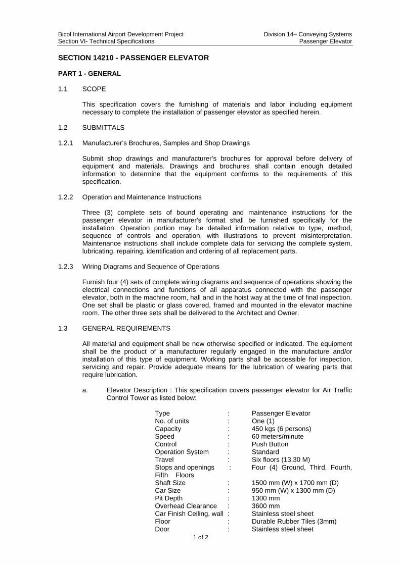
SECTION 14210 - PASSENGER ELEVATOR PART 1 - GENERAL 1.1 SCOPE
This specification covers the furnishing of materials and labor including equipment necessary to complete the installation of passenger elevator as specified herein.
1.2 SUBMITTALS
1.2.1 Manufacturer’s Brochures, Samples and Shop Drawings
Submit shop drawings and manufacturer’s brochures for approval before delivery of equipment and materials. Drawings and brochures shall contain enough detailed information to determine that the equipment conforms to the requirements of this specification.
1.2.2 Operation and Maintenance Instructions
Three (3) complete sets of bound operating and maintenance instructions for the passenger elevator in manufacturer’s format shall be furnished specifically for the installation. Operation portion may be detailed information relative to type, method, sequence of controls and operation, with illustrations to prevent misinterpretation. Maintenance instructions shall include complete data for servicing the complete system, lubricating, repairing, identification and ordering of all replacement parts.
1.2.3 Wiring Diagrams and Sequence of Operations
Furnish four (4) sets of complete wiring diagrams and sequence of operations showing the electrical connections and functions of all apparatus connected with the passenger elevator, both in the machine room, hall and in the hoist way at the time of final inspection. One set shall be plastic or glass covered, framed and mounted in the elevator machine room. The other three sets shall be delivered to the Architect and Owner.
1.3 GENERAL REQUIREMENTS
All material and equipment shall be new otherwise specified or indicated. The equipment shall be the product of a manufacturer regularly engaged in the manufacture and/or installation of this type of equipment. Working parts shall be accessible for inspection, servicing and repair. Provide adequate means for the lubrication of wearing parts that require lubrication.
a. Elevator Description : This specification covers passenger elevator for Air Traffic
Control Tower as listed below: Type : Passenger Elevator
No. of units : One (1) Capacity : 450 kgs (6 persons) Speed : 60 meters/minute Control : Push Button Operation System : Standard Travel : Six floors (13.30 M)
Stops and openings : Four (4) Ground, Third, Fourth, Fifth Floors
Shaft Size : 1500 mm (W) x 1700 mm (D) Car Size : 950 mm (W) x 1300 mm (D) Pit Depth : 1300 mm Overhead Clearance : 3600 mm Car Finish Ceiling, wall : Stainless steel sheet Floor : Durable Rubber Tiles (3mm) Door : Stainless steel sheet
Bicol International Airport Development Project Division 14– Conveying Systems Section VI- Technical Specifications Passenger Elevator
2 of 2
Door Type : 2-panel sliding doors (2S) Entrance Finish Jamb : Stainless Steel Hairline Electric Power Supply : 460 VAC, 3 Phase, 60 Hertz Electric Lighting Supply: 220 VAC, 1 Phase, 60 Hertz
PART 2 - PRODUCTS 2.1 Electric Passenger Elevator shall be product of reliable and experienced manufacturers
providing the most up-to-date technology, safety, quality and regular service maintenance.
PART 3 - EXECUTION
3.1 INSTALLATION
Install electric elevator in accordance with manufacturer’s standard instructions and procedures. Installation shall comply with requirements and rules set by the public authority of competent jurisdiction on elevators. Testing and adjustments shall be performed prior to final acceptance.
3.2 FINAL INSPECTION
After all necessary testing has been performed, the elevator contractor shall provide evidence of certification by a government authority for the project area, starting that each elevator safety has been tested and approved for use with the equipment having the specific ratings indicated or specified.
4.0 METHOD OF MEASUREMENT The quantity to be paid for shall be the number of elevators installed as completed units in place, accepted and ready for operation.
5.0 BASIS OF PAYMENT
The quantity measured as prescribed in Method of Measurement shall be paid for at the contract unit price for Passenger Elevators which price and payment shall be full compensation for furnishing all materials including accessories and for all preparation, assembly and installation of these materials, and for all labor, equipment, tools and incidentals necessary to complete the work prescribed in this Section.
Payment will be made in accordance with the Bill of Quantities.
******
Related Documents