Next Generation of Sirius Super Capacitor Module Monitoring Platform User Manual April 1, 2020 Amber & Waseem Dubai

Welcome message from author
This document is posted to help you gain knowledge. Please leave a comment to let me know what you think about it! Share it to your friends and learn new things together.
Transcript

Next Generation of Sirius Super Capacitor Module Monitoring Platform
User Manual
April 1, 2020
Amber & Waseem Dubai

1
Introduction
Sirius VIEW is next generation of Sirius Supercapacitor Module Monitoring Platform. It is
developed for adapting your system to new IOT platforms and technologies. After Sirius VIEW
your Sirius Super Capacitor Module will not be only energy storage unit, also will be IOT device
with online monitoring and control capabilities.
Sirius VIEW Ver:4 New Features
- Plug and Play over USB port, no need configuration to start monitoring Sirius Module
- Monitoring one or multiple modules seamlessly.
- Improved and upgraded user interface.
- Compatible with 1288x800, 1366x768, 1440x900, 1536x864 and 1920x1080 display
resolutions.
- User account control system with different account definitions.
- Enabling online monitoring and controlling the Sirius Energy Storage Module.
- In case of need, (Stolen) capability to block Sirius Energy Storage Module.
- Compatible with Windows 7 and newer versions.
- In case of update, automatic notification and quick installation.
- Sirius VIEW Mobile Android application connectivity.
- Data Logging Daily & Hourly (log per minute).
- Daily Event Logging.
- Daily Voltage & Current Measurement History.

2
Sirius VIEW Dashboard
Sirius VIEW Dashboard is the main page of the application. Dashboard page enables the user
get to know about Sirius Storage Module in one glance. Dashboard page has 12 different
sections.
1) Dashboard Buttons
1.1 Login Button
User can monitor Sirius Energy Storage Unit without any login procedure.
However, user needs to login to any functionality except monitoring. Application
starts as GUEST account which is only enabling monitoring. For:
- Configuration
- Calibration
- SD Card Reading
- Firmware Update
features, user should login as ADMIN, ENGINEER OR TECHNICIAN

3
1.2) Configure Button
After user login from button section, configure menu could be activated by
pressing Configure button. Configure button will enable user to configure and
calibrate module as per requirements.
Login required.
1.3) Details Button
User can get all the manufacture details about module which is based on Serial
number of Sirius Storage Module like:
- Nominal Voltage
- Monitoring Type
- Communication Type
- Manufacture Date
- Protection Type
No login required.
1.4) Alarms Button
User can monitor all the alarm condition rules like:
- High Voltage Alarm conditions
- High Current Alarm conditions
- High Temperature Alarm conditions
- Low Voltage Alarm conditions
No login required.
1.5) Show Module/Cells Button
User can select monitoring Cell Voltage Levels or main measurements of Sirius
Module which has same characteristics as front LCD display.
No login required.

4
1.6 Refresh Connection Button
In case of any communication interruptions like USB Cable problems or module
USB port problems, user can press “Refresh” button to refresh communication
ports to start new session
No login required.
1.7 Show path Button
Sirius VIEW Application has multiple data logging features as;
- Daily Generated Measurement Report (Log per minute)
- Hourly Generated Measurement Report (Log per minute)
- Daily Event Report (Log per event)
“Show path” button will pop up each file path on Windows Explorer, if the report is generated.
No login required.
1.8 Mobile App Button
Sirius VIEW has also Android Mobile Application which can be downloadable from
Google Play. Sirius Mobile Application enables users to monitor and control their
module from anywhere internet.
No login required.
https://play.google.com/store/apps/details?id=com.siriusmobile.siriusviewrealdataapp
1.9 Logout Button
Users can logout from Sirius VIEW Application and change their account name as
“GUESS”. Users can use that button to make module safe to keep monitor when
they leave pc, so that way third parties will not be able to configure or calibrate
Sirius storage module.
1.10 Exit Button
Users can terminate Sirius VIEW application safely by pressing “Exit button”.

5
2) Top Banner & Indicators
2.1 Application Logo
Sirius VIEW has unique logo to be recognized by users.
2.2 Connection Indicator
When USB Communication established successfully, indicator should show as “Connected”. In
case of any communication failure, it will indicate as “Disconnected”.
2.3 Communication Baud rate Indicator
Sirius VIEW would have different versions which use different baud rates. This section can
indicate which baud rate is used for communication.
2.4 Communication Port Indicator
Sirius VIEW choose COM ports automatically without user interaction, this section indicates
which COM port is used for chosen serial number of modules
2.5 Time & Date Indicator
This part indicates the time and date of PC which Sirius VIEW runs
2.6 User Name Indicator
Users can use different accounts for Sirius VIEW which are GUESS, ADMIN, ENGINEER and
TECHNICIAN. This section indicates which user account is active.
2.7 Module Status Indicator
This section indicates if module is:
- Charging (Positive Terminal Current)
- Standby (No Terminal Current)
- Discharging (Negative Terminal Current)

6
3) Main Measurements Indicators
This section indicates all the vital measurements of Sirius Energy Storage Module in real time.
3.1 Terminal Voltage Indicator
“Terminal Voltage” represents the calibrated voltage of Terminal of Sirius Energy Storage
Module when Terminal is ENABLED.
3.2 Terminal Current Indicator
“Terminal Current” represents the calibrated current of Terminal of Sirius Energy Storage
Module when Terminal is ENABLED
3.3 Life Energy Indicator
“Life Energy” represents the total discharged energy from first turning on the module. This
indicator should indicate 0KW when users start to use module first time. This indicator value
should start increase while any discharging session.
3.4 State of Charge (SOC) Indicator
“State of charge” represents the percentage of Sirius Module Capacity.
3.5 Terminal Temperature Indicator
“Terminal Temperature” represents the temperature of terminals as Celsius.
3.6 Cell Temperature Indicator
“Cell Temperature” represents the temperature of Cell Banks as Celsius.

7
4) System Status Indicators
This section indicates all the alarms, warnings and status of main features of Sirius Module.
4.1 Voltage Status Indicator
Voltage status indicates if there is any alarm occurred on Sirius Module regarding Voltage
measurements. Alarms can be: Cell Too Low, Low Battery, Batt Full, Contact Service.
4.2 Current Status Indicator
Current status indicates if there is any alarm occurred on Sirius Module regarding Current
measurements. Alarms can be: Over current, tolerate (tolerating till alarm flag rise).
4.3 Temp. Status Indicator
Temp. status indicates if there is any alarm occurred on Sirius Module regarding Temperature
measurements. Alarms can be: Cell Over Temperature and Terminal Over Temperature.
4.4 Terminal Status Indicator
Terminal status indicates if terminal is enabled or disabled. For any charging or discharging
session, terminal should be enabled.
4.5 SD Status Indicator
SD Status indicates if internal SD Card data logging works properly or not. Status can be:
Logging: SD Card logging main measurements while module is turned on
Standby: SD Card is functional but data logging disabled.
Error: SD Card hardware may be damaged or RTC value needs to time update.

8
4.6 RTC (Real Time Clock) Status Indicator
RTC Status indicates if RTC works properly or not. Status can be:
Running: RTC works properly and functional.
Need set: RTC is functional but needs calibration.
Not Running: RTC may be not functional or needs calibration.
4.7 Balance Status Indicator
Sirius Module has balancing feature to balance multiple cell voltages. If user has admin or
engineer account, it can be activated. This indicator shows if balancing feature is activated or
not.
account, it can be activated. This indicator shows if balancing feature is activated or not.
4.8 Dry Contact Status Indicator
Some Sirius Modules has multiple Dry Contact output feature. User can activate it by
“Configure” button. This indicator shows if Dry contact feature is activated or not.
Dry contact configuration setup can be handle by pressing “CONFIGURE” button and selecting
“Terminal Configuration”

9
5) Real-Time Graphs
Sirius VIEW provides multiple functional graphs to users to monitor Sirius Module in different
aspects like:
- Instant Main Measurement Graphs (Voltage, Current, Temperature, Cell Voltage)
- Hourly Terminal Voltage Graph
- Hourly Terminal Current Graph
5.1 Instant Main Measurement Graphs
Instant Main Measurements Graphs provides instant Terminal Current, Cell & Module
Temperature, Cell Voltages, Terminal Voltage graphs which can be refreshed every 1 second.
Refresh rate will depend on how many modules are monitored at same time. Refresh rate will
be decreased by number of monitored module.
Current and Voltage Graphs can show multiple values in case of monitoring multiple modules at
same time. All cell Voltage graph will only show the value of chosen module.
Temperature Graph will show both Terminal and Cell Temperature value of chosen module.

10
5.2 Hourly Voltage Graphs
Hourly voltage graphs are presented on Sirius VIEW by voltage readings of every hour. Hourly
measurement will be logged on online database and read every hour. For best functionality,
host pc should be connected to internet. Hourly graphs will be refreshed every 24 hours.
5.3 Hourly Current Graphs
Hourly current graphs are presented on Sirius VIEW by current readings of every hour. Hourly
measurement will be logged on online database and read every hour. For best functionality,
host pc should be connected to internet. Hourly graphs will be refreshed every 24 hours.

11
6) Cell Voltages & Main Measurements Indicator
Sirius VIEW enables users to monitor Sirius Module in detail or overall in one glance. Users can
read each cell voltages or general measurements of every modules which connected
monitoring system.
6.1 Sirius Cell Voltages Indicator
Sirius VIEW provides cell voltage monitoring one by one as voltage reading. User can monitor
cell voltages on real-time. Cell number can change by nominal voltage and monitoring type of
Sirius Module. Cell numbers can be: 5,10,20. User can choose that Indicator by pressing “Show
Cell Button”
6.2 Sirius All Modules Indicator
Users can read main measurements of all the modules which are connected to monitoring
system at same time. This function can be very useful while working with multiple modules.
User can choose that Indicator by pressing “Show All Button”

12
7) Sirius Module Measurement Statistics
7.1 Max Terminal Voltage
Terminal Voltage of Sirius Module is logged and processed every second and processed and
resulted as Maximum Terminal Voltage parameter.
7.2 Min Terminal Voltage
Terminal Voltage of Sirius Module is logged and processed every second and processed and
resulted as Minimum Terminal Voltage parameter.
7.3 Max Cell Voltage
Cell Voltages of Sirius Module is logged and processed every second and processed and
resulted as Maximum Cell Voltage parameter.
7.4 Min Cell Voltage
Cell Voltages of Sirius Module is logged and processed every second and processed and
resulted as Minimum Cell Voltage parameter.
7.5 Max Cell Temperature
Cell Temperature of Sirius Module is logged and processed every second and processed and
resulted as Maximum Cell temperature parameter.
7.6 Min Cell Temperature
Cell Temperature of Sirius Module is logged and processed every second and processed and
resulted as Minimum Cell temperature parameter.

13
8) Event Logger Indicator
Sirius VIEW does not only log measurements of Sirius Module but also logging any event based
on user or module functionality. Sirius VIEW logs event by serial number of event owner, time
& date and event name. These can be events to log;
- Terminal status change
- User account change
- OTP request result
- Charging/Discharging
- Alarm conditions
- Communication status
- Configuration update
- Calibration update
These events will be recorded daily basis and event log file will be bases on serial number of
module or modules.
9) Event Logger Filter
User can filter Event Logger Indicator to show specific events like;
- Alarm Events
- General Events (All Events)
- Login Events
- Configuration Events

14
10) Calibration and Online Database Status
All the Sirius Modules are calibrated and configured before shipping but
some extreme conditions cause modules to lose their calibrations or
configurations. Sirius VIEW let users to know exact calibration and
configuration status of their Sirius Modules.
10.1 Current Calibration
Current calibration of Sirius Module done before shipment with high
accurate sensors. If calibration memory of Sirius Module is not damaged,
this parameter should be indicated as CALIBRATED.
10.2 No Load Calibration
No load calibration means offset current on terminal. It can be called as
ghost value on sensor. This value already configured before shipment with
high accurate sensors. If calibration memory of Sirius Module is not
damaged, this parameter should be indicated as CALIBRATED. If there is a
current reading on display while there is no load connected to module, user
may need to configure no load current by pressing CONFIGURE button.
10.3 Temperature Calibration
Temperature calibration of Sirius Module done before shipment with high accurate sensors. If
calibration memory of Sirius Module is not damaged, this parameter should be indicated as
CALIBRATED.
10.4 Capacity Calibration
Capacity calibration of Sirius Module done before shipment with high accurate sensors. If
calibration memory of Sirius Module is not damaged, this parameter should be indicated as
CALIBRATED.
10.5 Quality Check Status
Every Sirius Module has quality check testing by professionals after all the calibration sessions.
If calibration memory of Sirius Module is not damaged, this parameter should be indicated as
CHECKED.
10.6 Online Database Status
Sirius VIEW has online database, enables users to monitor their module from anywhere has
internet. If there is internet connection on host pc, status should indicate as “DATABASE
CONNECTED”. If this one indicates DISCONNECTED even pc is connected internet, user need to
press “REFRESH” button

15
11) Bottom Banner and Indicators
11.1 Firmware Version Indicator
Each Sirius Module has unique firmware with version regarding its specs. Whenever there is
new version of firmware is release from A&W, Sirius VIEW Application will notify user (Internet
Required). User can use that indicator for checking if firmware version is the up-to -date.
11.2 Serial Number Indicator
Sirius VIEW application enables user to monitor and control multiple modules, but only one
module can be monitored configured & calibrated at a time. This indicator shows which module
is selected, if user needs to change module serial number to monitor it, they can use “Select
Module Control” below.
11.3 Instant System Log Indicator
System log indicates the last command executed while communicating with Sirius Modules.
Commands can be;
- COM port status
- Measurement Acquisition
- Time & Date Acquisition
Instant System log is not logging data to any file. This feature can be only informative at run-
time.
12) Energy Transfer Indicator
This indicator can inform user to how much energy is charged or discharged while application is
running. Indicator values will be keep calculated while app is running (no interruptions).
Indicator values will be reset when
-Application is terminated.
-Pressed “Refresh” button or pressed “Configuration” button .
16
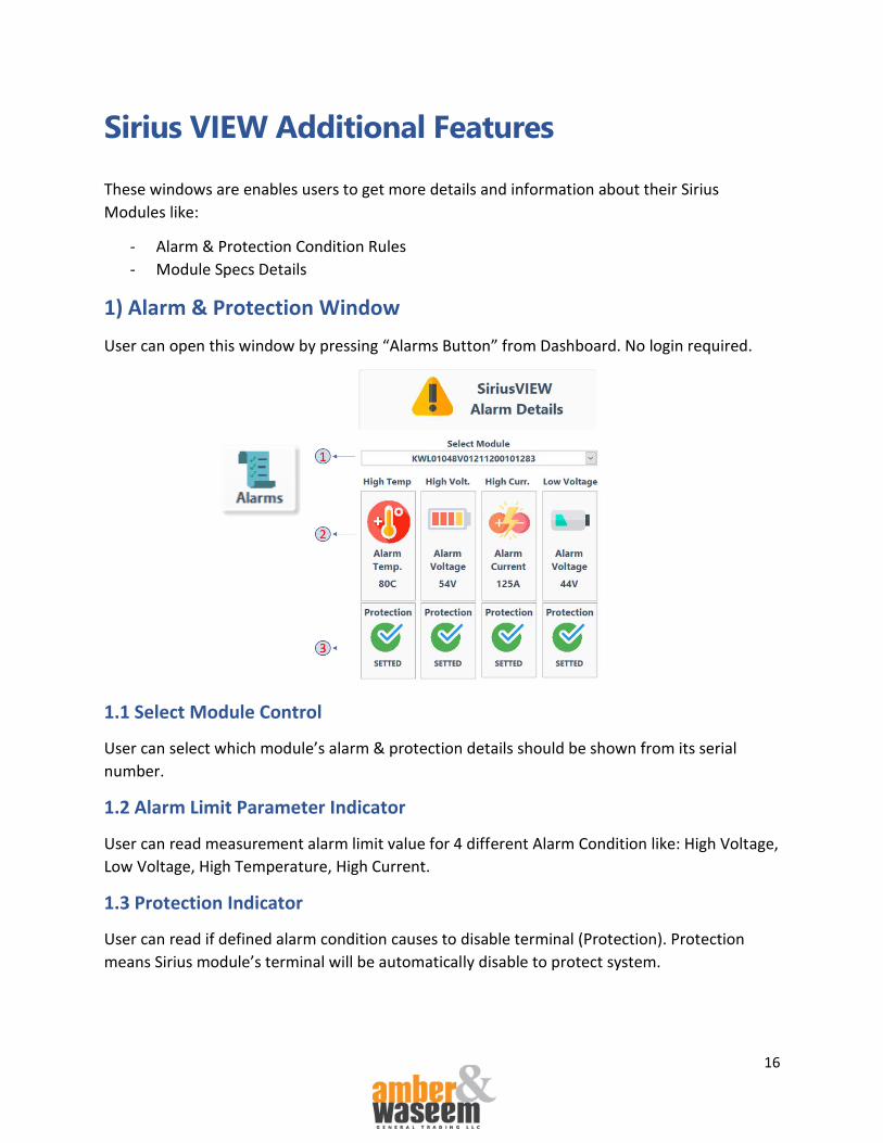
Sirius VIEW Additional Features
These windows are enables users to get more details and information about their Sirius
Modules like:
- Alarm & Protection Condition Rules
- Module Specs Details
1) Alarm & Protection Window
User can open this window by pressing “Alarms Button” from Dashboard. No login required.
1.1 Select Module Control
User can select which module’s alarm & protection details should be shown from its serial
number.
1.2 Alarm Limit Parameter Indicator
User can read measurement alarm limit value for 4 different Alarm Condition like: High Voltage,
Low Voltage, High Temperature, High Current.
1.3 Protection Indicator
User can read if defined alarm condition causes to disable terminal (Protection). Protection
means Sirius module’s terminal will be automatically disable to protect system.

17
2) Module Details Display
User can open this window by pressing “Details Button” from Dashboard. No login required.
2.1 Select Module Control
User can select which module’s details should be shown from its serial number. No login
Required.
2.2 Communication Type Indicator
It indicates which communication method is implemented to module which is selected
2.3 Production Date Indicator
It indicates manufacture date of Sirius module as month and year. This information can be used
for any tech. support or enquiries.
2.4 Protection Type Indicator
It indicates which protection method is implemented to module which is selected.
2.5 Monitoring Type Indicator
It indicates which monitoring method is implemented to module which is selected.
2.6 Nominal Voltage Indicator
It indicates which nominal voltage is implemented to module which is selected.
2.7 Capacity Indicator
It indicates how much capacity is implemented to module which is selected.

18
Sirius VIEW Login Procedure
Sirius VIEW enables “qualified users” to configure their Sirius Modules regarding their
applications and requirements. Sirius VIEW uses account control for safety of Sirius Module
configurations. Any kind of configuration requires login as: Engineer, Technician and Admin.
Login process contain two steps:
1. Local password protection.
2. OTP code protection.
1) Local Password Protection
Sirius VIEW has 4 different qualified accounts for login as and these 4 accounts and they have
different passwords and functionalities. For user, only “Technician” account can be accessible.
“Engineer” and “Admin” accounts only can be reachable by qualified engineer from A&W.
Account Name Default Account Password Account is allowed to Guest No Password required Only Monitoring
Engineer Contact with A&W support All Functionality
Technician “TECHNICIAN” All Functionality except Configuration & Calibration
Admin Contact with A&W support All & Special functionalities
Each time application executed or “logged out”, user will have “GUESS” account automatically.
These passwords are pc specific, not Sirius module base. It means, users can use same
password and account name for different Sirius Modules without any issue.
2) OTP Code Protection
If local password is entered correctly, Sirius VIEW will generate token number for OTP code and
user will be asked to enter OTP code which has specs as:
- Just one-time use code
- Every hour code will be changed
- Unique to each Sirius Module
- Only can be generatable by Sirius VIEW Android Mobile App
- In case of any suspicious condition, user can be blocked

19
3) Sirius VIEW Detailed Login Procedure
1. Press “Login button” and select User account name and account’s password correctly
2. Sirius VIEW desktop app will generate TOKEN number for OTP code
3. Open up Sirius VIEW Mobile App.
4. Add Sirius Module with its serial number and “Admin account’s password” (Just one
time)
5. Open up “List product Page” from Sirius VIEW Mobile App and find used module and
press generate OTP button
6. Enter Token number which is generated by Sirius VIEW Desktop App
7. Copy OTP Code, generated by mobile app
8. Enter copied OTP code into Sirius VIEW Desktop application
9. Press Run Application Button.
If all the steps are done successfully, user will be enabled to finish login and do Sirius VIEW
configurations.

20
Sirius VIEW Module Configuration
“Qualified User” accounts can only configure Sirius Module
over Sirius VIEW desktop application. For being qualified, user
should login properly as explained previous section. If user
haven’t logged in, and try to enter configuration page by
pressing “Configure” button, Sirius VIEW application will notify
user as below.
Users can do 8 different configurations with Sirius VIEW. Most
of the configuration can be done by any user account, but
there are configurations only can be done with ENGINEER or
ADMIN accounts like:
- Firmware Settings
- Module Configuration
- Module Calibration

21
1) SD Card Settings
Users can do configurations for internal SD Card which enable background data logging for
every minute (while Sirius module is turned on).
1.1 SD Card Logging Control
Sirius VIEW enables users to enable & disable SD Card logging in case of need. User just need to
select SD card logging status and press “Update” button.
1.2 SD Card Triggering Control
In case of SD Card hardware failure, users can restart SD card module by enabling SD card
triggering option. User just need to select trigger status and press “Update” button.
SD Card triggering will restart the Sirius Module to trigger SD card logging.
1.3 SD Card Size Reading Control
Users can read total consumed SD card size while logging Sirius module’s measurements. SD
card logged data every 1 minute with time stamp and keep maximum last 30 days of data. In
another words, SD card consumption cannot be more than 4 MB. (Size of SD card: 4GB). Output
of this control will have unit as byte.

22
1.4 SD Card Reading
Users can extract all the logs from internal SD card by pressing “Read” button. But there are
some conditions should be met for reading SD card properly:
- SD Card Logging should be “Enabled”
- There should be at least one row of data in SD card (at least 1 minute of data)
- There should not be any RTC failure.
1.4.1 SD Card Reading Table
SD card reading of Sirius Module will be show up after reading process. This process can take 1
minutes to 15 minutes regarding the size of record. SD card will record vital measurements of
module as a minute periods with time stamps. Whenever SD card reading is done, Sirius VIEW
will log all the data as Excel report.
1.4.2 SD Card Logging Path
SD card logging will reside on same folder with Sirius VIEW application. In case of user want to
reach this location, SD card logging path button can be used.

23
2) Firmware Settings
Each Sirius Modules installed with unique firmware depends on their specs and configurations.
That firmware can be improved and updated through time, thanks to Firmware settings, users
can update their Sirius Module firmware version.
2.1 Get Firmware Date
Before calibrating the firmware, user may want to see the date of Firmware version to be sure,
if the update is obligated or not.
2.2 Firmware Update
Firmware calibration will be done regarding the serial number of Sirius Module by pressing
Firmware Update button. While update, module will be in sleeping mode. Do not turn off any
switch or remove any communication cables. Procedure can take maximum 1 minute.

24
3) Time (RTC) Settings
Each Sirius Module has internal real time clock to keep SD card logging has correct time stamp.
This stamp may change regarding user request by pressing “Update” button. (1)
User just need to select required Time and Date settings. (2)
4) Terminal Settings
4.1 Toggle Terminal Status
Users which are physically cannot beside module, they can control their module remotely and
toggle the terminal status by choosing Disabled/Enabled and pressing “Update” button.
4.2 Activation Status
Activation Feature: Sirius Module’s terminal will be disabled till user enable it physically (by
pressing fault reset button). This feature can be chosen to secure module terminals in case of
any danger while turning on Sirius Module.
4.3 Zero Current Calibration
Terminal Current Sensor of Sirius Module can have small offset value because of long storage
period or temperature effect. Users can correct current reading of Sirius Module by doing zero
current calibration. Module terminal should be disabled while this calibration.

25
4.4 Dry Contact Status
Some Sirius Modules has dry contact feature that module can give custom output regarding any
requirement like;
- Terminal Voltage Status
- SOC Percentage Status
- Terminal Temp. Status
- Terminal Status
4.4.1 Example Operation (Functionality: Low Terminal Voltage)
The Dry Contact will short its respective pins when the Total Voltage drops lower than or equal
to the Turn ON (Enable on Sirius VIEW) Value. It will open its respective pins if the Total Voltage
is higher than the Turn OFF (Disable on Sirius VIEW) Value.
If Total Voltage is equal or lower than the Turn ON Value (Total Voltage <= Turn ON Value)

26
If Total Voltage is greater than the Turn OFF Value (Total Voltage > Turn OFF Value)
Turn OFF value is greater than Turn ON value because the Dry Contact should not function if
the condition of Low Voltage is not met. Dry Contact is always shut OFF if the total voltage did
not drop lower than the Turn ON value. This is to detect whether the module dropped or higher
than the preferred voltage value. Put a little difference between Turn ON and Turn OFF value to
accommodate the bounce back of voltage during charging and discharging
4.4.2 Example Operation (Functionality: SOC Percentage)
The Dry Contact will short its respective pins when the Total Voltage drops lower than or equal
to the Turn ON (Enable on Sirius VIEW) Value. It will open its respective pins if the Total Voltage
is higher than the Turn OFF (Disable on Sirius VIEW) Value.
If the module has equal or higher SOC than Turn ON (Enable) value, dry contact pins will get
shorted. If the module has lower SOC than Turn OFF (Disable) value, dry contact pins will get
OPEN.
If State of Charge is equal or greater than the Turn ON Value (SOC >= Turn ON Value)
If State of Charge is lower than the Turn OFF Value (SOC < Turn OFF Value)
For more detailed information about Dry Contact feature, please go to A&W website and read
“Sirius Module Dry Contact Manual”

27
5) LCD Settings
5.1 LCD Contrast
Changing light conditions, user can choose best contrast value for visibility of Sirius Module LCD
screen.
5.2 Low Power Status
In case of saving energy from Sirius Module, user can decrease some non-vital performance of
Sirius Module like communication and led backlighting by using this feature. There will be no
difference at module energy storage specs even in low power mode.
6) Balancing Settings
6.1 Generic Balancing
Sirius Module has 2 different balancing features. First one as generic balancing can be enabled
by user for balancing module while module is at STANDBY. (no negative or positive current).
Generic balancing simply discharges module cells which has more voltage than others.
Whenever module is balanced, generic balancing will be disabled automatically.
6.2 Sirius Balancing
Sirius balancing can be used while only CHARGING condition. Sirius balancing can control
charge current amplitude by PWM algorithm to equalize cell voltage of Sirius Module.
Whenever module cells are balanced, Sirius balancing will be disabled automatically.

28
7) Module Configuration
Sirius Modules have 4 different alarm conditions which user can enable or disable or change
alarm limits in case of need.
All Sirius Modules have their default alarm limits base on their specs. All these alarms are
already configured and checked at A&W facilities by professionals
7.1 Alarm Limits
Sirius Modules have 4 different alarm configuration limits which are belongs Temperature,
Terminal Voltage, Terminal Current. User can change default configuration limits manually in
case of need.
7.1 Alarm Protections
Sirius Modules have all the alarms settings with protection feature as default. Protection
feature: In case of any alarm condition, module terminals will be disabled automatically till the
alarm condition is passed. This feature can be not suggested in case of critical applications like
telecom or military. In critical applications, user may consider to disable protection (auto
terminal disabling) feature to keep terminals on even in alarm condition.

29
8) Module Calibration
Each Sirius modules are both configured and calibrated before shipment but electronic sensors
can lose their calibrations by harsh environment conditions like high & low temperature or
vibration. Users can re-calibrate the sensor measurements of Sirius Module anytime. Only
required 3rd party devices would be multimeter, clamp meter and thermometer for
calibrations.
8.1 Calibration monitoring
Sirius VIEW enables users to monitor Sirius modules while calibration on real – time. Users can
easily see the result of calibration even they calibrate their system remotely.
8.2 Calibration Method
Users can do 3 different calibration as
- Terminal Voltage
- Terminal Current
- Terminal Temperature.
For calibration any of these 3 parameters, user just need to enter their sensor measurements
(from multimeter…) into Sirius VIEW application and press “Calibrate” button.

30
Updating Sirius VIEW Automatically
Sirius VIEW platform is continuously under development to serve our customers better. During
development, our engineers will release new versions of Sirius VIEW. Whenever there is new
release, it will be announced over Sirius VIEW Mobile Application, also Sirius VIEW desktop
application will give notification to user to update the version automatically.

31
Sirius VIEW FAQ
Q) Sirius Module is connected to pc and running but communication for Sirius VIEW does not
start, what should I do?
A) There can be many reasons for that issue, multiple reasons and solutions are mention below
- If system uses USB Hub, try to communicate over multiple USB ports of pc, not USB Hub.
- Use another port of PC
- Use another USB cable between Sirius Module and PC
- If Sirius VIEW app is already executed, press “REFRESH” button
Q) How I will be sure my Sirius VIEW app is up-to-date?
A) if PC is already connected to internet, Sirius VIEW can check most updated version and
current version and give automatic notification to user, in case of update, user will be notified
about update procedure.
Q) How I will log in and get password to configure system?
A) There are multiple credentials and accounts for Sirius VIEW shown below
Account Name Default Account Password Account is allowed to
Guest No Password required Only Monitoring
Engineer Contact with A&W support All Functionality
Technician “TECHNICIAN” All Functionality except Configuration & Calibration
Admin Contact with A&W support All & Special functionalities
As default, user can only access TECHNICIAN account to do basic configurations. If users need to
reach another account, A&W support team will help about the procedure.
Related Documents