Chapter 6 Next Generation of Engineering Methods and Tools for SOA-based Large-scale and Distributed process applications Robert Harrison, C. Stuart McLeod, Giacomo Tavola, Marco Taisch, Armando W. Colombo, Stamatis Karnouskos, Marcel Tilly, Petr Stluka, François Jammes, Roberto Camp, Jerker Delsing, Jens Eliasson, J. Marco Mendes Abstract Engineering methods and tools are seen as key for designing, testing, deploying and operating future infrastructures. They accompany critical processes from “cradle-to-grave”. Here we provide an overview of the user and business re- quirements for engineering tools, including system development, modelling, visu- alisation, commissioning and change in an SOA engineering environment. An ap- praisal of existing engineering tools appropriate to IMC-AESOP, both commercial and development prototypes are presented, culminating in the presentation of tool Robert Harrison, Stuart McLeod University of Warwick, UK e-mail: [email protected],[email protected] Giacomo Tavola, Marco Taisch Politecnico di Milano, Italy e-mail: [email protected],[email protected] Armando W. Colombo Schneider Electric & University of Applied Sciences Emden/Leer, Germany e-mail: armando. [email protected],[email protected] Stamatis Karnouskos SAP, Germany e-mail: [email protected] Marcel Tilly Microsoft, Germany e-mail: [email protected] Petr Stluka Honeywell, Czech Republic e-mail: [email protected] François Jammes Schneider Electric, France e-mail: [email protected] Roberto Camp FluidHouse, Finland e-mail: roberto.camp@fluidhouse.fi Jerker Delsing, Jens Eliasson Luleå University of Technology, Sweden e-mail: [email protected],[email protected] J. Marco Mendes Schneider Electric, Germany e-mail: [email protected] 1

Welcome message from author
This document is posted to help you gain knowledge. Please leave a comment to let me know what you think about it! Share it to your friends and learn new things together.
Transcript
Chapter 6Next Generation of Engineering Methods andTools for SOA-based Large-scale andDistributed process applications
Robert Harrison, C. Stuart McLeod, Giacomo Tavola, Marco Taisch, Armando W.Colombo, Stamatis Karnouskos, Marcel Tilly, Petr Stluka, François Jammes,Roberto Camp, Jerker Delsing, Jens Eliasson, J. Marco Mendes
Abstract Engineering methods and tools are seen as key for designing, testing,deploying and operating future infrastructures. They accompany critical processesfrom “cradle-to-grave”. Here we provide an overview of the user and business re-quirements for engineering tools, including system development, modelling, visu-alisation, commissioning and change in an SOA engineering environment. An ap-praisal of existing engineering tools appropriate to IMC-AESOP, both commercialand development prototypes are presented, culminating in the presentation of tool
Robert Harrison, Stuart McLeodUniversity of Warwick, UK e-mail: [email protected],[email protected]
Giacomo Tavola, Marco TaischPolitecnico di Milano, Italy e-mail: [email protected],[email protected]
Armando W. ColomboSchneider Electric & University of Applied Sciences Emden/Leer, Germany e-mail: [email protected],[email protected]
Stamatis KarnouskosSAP, Germany e-mail: [email protected]
Marcel TillyMicrosoft, Germany e-mail: [email protected]
Petr StlukaHoneywell, Czech Republic e-mail: [email protected]
François JammesSchneider Electric, France e-mail: [email protected]
Roberto CampFluidHouse, Finland e-mail: [email protected]
Jerker Delsing, Jens EliassonLuleå University of Technology, Sweden e-mail: [email protected],[email protected]
J. Marco MendesSchneider Electric, Germany e-mail: [email protected]
1
Harrison et al.6.1. Introduction
cartography graphically, defining the impact of these tools within the enterprise andsystem lifecycle.
6.1 Introduction
Engineering of a new generation of very large-scale SOA-based distributed sys-tems for batch and continuous process applications requires a new generation ofmethods and tools. They need to support the lifecycle (e.g., design, configuration,management and support) of new SOA-based system architectures, which must pro-vide SCADA functional capabilities to meet user requirements for much greaterdistributed control and decision-making abilities than current DCS system imple-mentations.
Some 50% of the DCS platforms running process plants today are at least 20years old with a large number of these at the end of their lifecycle. They typicallycontain a mishmash of technology, which in turn requires a wide range of ad-hoc en-gineering tools and methods to support them, limiting integration both vertically andhorizontally and making reconfiguration of systems, or their optimisation, difficultto achieve effectively. There is a growing need to meet various migration require-ments for both small and large system configurations in an efficient manner, and thiscapability, to be provided via the identified core IMC-AESOP technology, needs tobe supported via specific engineering tools.
The shift from systems implemented via a predominantly centralised paradigmto control and monitoring strategies based on a system of systems engineering ap-proach [16, 15] with thousands of dynamic SOA-compliant devices requires a newengineering methodology with requirements for new modelling and engineering ap-proaches in order to enable such systems to be practically realised.
The approach adopted on the IMC-AESOP project was driven by user require-ments derived from the studied use cases. These determined the required tools forthe considered SOA process control application(s), from which a tool cartographyhas been created, as described in this chapter. In areas where suitable existing toolseither did not exist or lacked adequate functionality, new tools were developed orexisting ones extended to meet the requirements of the use cases. These are detailedin section 6.3 along with the requirements they fulfil, how they were implemented,and the results they produced.
The IMC-AESOP project has addressed the issues of DCS across differing indus-trial/business domains, as highlighted by the different use cases, from real-time lu-brication of mining machinery to heating management systems and district-heatingapplications. The requirements of these applications are broad, and the engineeringcontent in each varies significantly. However, Section 6.4 describes how each of thetools is used and categorises them as per their architectural level for each use case.Finally the IMC-AESOP toolkit is identified, highlighting the tools recommendedto build the selected applications.
2
This is a preprint version, which may deviate from the final version which can be acquired from https://www.springer.com/gp/book/9783319056234
Harrison et al.6.2. Engineering Methods and Cartography of Identified Tools
6.2 Engineering Methods and Cartography of Identified Tools
The first activity constitutes the identification of tools and methods that are relevantto the needs of the project, based on a study of the state of the art in engineer-ing tools and methods for the development and support of SCADA and DCS sys-tems. An overview is provided of the user and business requirements for engineer-ing tools, from the SOA, system modelling and change management, applicationand device design development and support perspectives. System simulation, visu-alisation, commissioning and optimisation were also considered, together with anoverview of system-of-systems engineering from a tools and methods perspective.
6.2.1 SOA engineering methods
The engineering of distributed embedded systems requires the modelling and sup-port of units of distributed functionality. Object-based specifications emphasizestructural decomposition, which facilitates the implementation of open and recon-figurable systems, whilst industrial software standards such as IEC 61131-3 [4] pro-vide mechanisms for functionally decomposing and programming and IEC 61499[6] describes the modelling of communicating distributed function blocks. In thiscase a system can be described as a composition of interacting components, such asfunction blocks or port-based objects, which are then mapped onto real-time tasks.Object and function-block based design uses a number of fundamental principlessuch as encapsulation, aggregation and association of objects or components to buildapplications.
However, whilst object- and component-based system software development iswell established in several domains, a major problem that has to be overcome is thecurrent informal and largely ad-hoc definition of application components. Ad-hocspecification and design may severely limit component reusability. Therefore, it ishighly desirable to develop a formal framework that will allow for a systematic spec-ification of reconfigurable components, which will be reusable by definition. Suchfactors needed careful consideration in the realisation of the IMC-AESOP systemarchitecture and middleware which promote the building of applications comprisinginteracting components from device level up to enterprise level.
6.2.2 System modelling, evolution and change management
In order to implement a smooth and consistent transition from a SCADA envi-ronment developed via a classical (and often inhomogeneous and improvised) ap-proach on proprietary, obsolete and rigid platforms into an open, standard, service-oriented one, appropriate tools need to be realized for system modelling, evolutionand change management.
3
This is a preprint version, which may deviate from the final version which can be acquired from https://www.springer.com/gp/book/9783319056234
Harrison et al.6.2. Engineering Methods and Cartography of Identified Tools
The concept of application engineering tools needs to be considered in a broadcontext including methodologies and soft skills in addition to the technological as-pects.
• From the system- and information-modelling perspectives support is needed forthe following:
– A representation of the industrial environment with a standard recognized syn-tax.
– The enrichment of models with related information as parameters, semanticinformation, links with other objects and conditional functionalities.
– The definition of a hierarchy (taxonomy).– An easy transposition in service architecture approach with automatic trans-
lation into XML syntax of metadata.
• Support for system change-management and evolution-management tools, al-though beyond the scope of IMC-AESOP, are crucial for effective lifecycle en-gineering. The management of change encompasses activities beyond data man-agement, including people management, motivation and the ability to identifykey factors in complex environments.
6.2.3 Application design
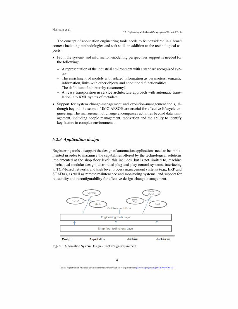
Engineering tools to support the design of automation applications need to be imple-mented in order to maximise the capabilities offered by the technological solutionsimplemented at the shop floor level; this includes, but is not limited to, machinemechanical modular design, distributed plug-and-play control systems, interfacingto TCP-based networks and high level process management systems (e.g., ERP andSCADA), as well as remote maintenance and monitoring systems, and support forreusability and reconfigurability for effective design-change management.
Fig. 6.1 Automation System Design – Tool design requirement
4
This is a preprint version, which may deviate from the final version which can be acquired from https://www.springer.com/gp/book/9783319056234
Harrison et al.6.2. Engineering Methods and Cartography of Identified Tools
In summary, key aspects of application engineering tool capabilities are the fol-lowing:
• Reconfiguration: Configuration and change of the application by the user.• Process description and validation: Control application defined in the user’s
terms.• Device support & maintenance: Support for embedded device.• Real-to-virtual connectivity: Integration with virtual engineering.• Process-to-business connectivity: Integration with business and production mon-
itoring/support applications.
6.2.4 Device development and support
Using SOA on embedded devices down on the factory floor can enable powerfulcross-layer possibilities. However, SOA protocols, originally developed for the en-terprise domain impose heavy restrictions on their usage on resource-constrainedembedded systems. This is especially true in the context of a Wireless Sensor andActuator Network (WSAN). The relatively low bandwidth of a wireless networkis a limiting factor for network performance when sensing very large packets. Thecommonly used protocol today for SOA in industrial automation is SOAP, using theverbose XML language. The use of XML drastically increases the size of a messagecontaining sensor data. However, XML has excellent support today from a largenumber of software vendors, which makes it an open and standardized way to ex-change data between devices from different manufacturers using different operatingsystems and applications. One benefit of the SOA approach is that message parserscan be automatically generated for each message class. This reduces the need tomanually write software for the serialisation of messages.
Today, the two most widely used operating systems for wireless sensor and ac-tuator networks are TinyOS from University of California in Berkeley, and Contikifrom the Swedish Institute of Computer Science, Stockholm, Sweden. Research iscurrently being performed by researchers in both academia and the industry to moveSOA technology down to sensor node level. The application of a widely used op-erating system combined with auto-generated message parsers enables system de-velopers to re-use the existing code base to a large extent and mitigates the need todevelop proprietary communication protocols. Today, gSOAP is a commonly used,proven, and stable tool to generate XML parsers. New solutions based on binaryXML, i.e. EXI, need new tools to be developed. The use of EXI will be an enablingtechnology for SOA-based wireless sensor and actuator networks.
5
This is a preprint version, which may deviate from the final version which can be acquired from https://www.springer.com/gp/book/9783319056234
Harrison et al.6.2. Engineering Methods and Cartography of Identified Tools
6.2.5 Simulation
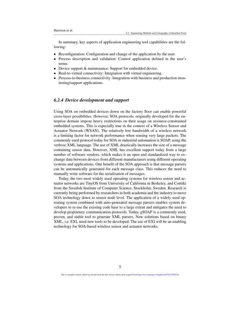
System simulation is advantageous both at design time and during the operationalphase. Simulation capabilities (i.e. the capabilities to simulate the time-dependent,dynamic system behaviours) can potentially provide strong support for testing vari-ous aspects of the system design in a virtual form prior to its final implementation inorder to minimise design errors and compress design time. Simulation capabilitiesneed to be provided for, and adapted to, each engineering application that the systemdesign involves (e.g. control, process, and mechanical) as shown in Fig. 6.2. How-ever, domain-dependent simulation capabilities should be integrated in a form thatwill enable multi-disciplinary engineering teams to assess the level of completionand quality of their specific design with regard to the characteristics and behavioursexpected of the final system.
Fig. 6.2 Overview of simulation capabilities of automation system design tools
6.2.6 System visualisation
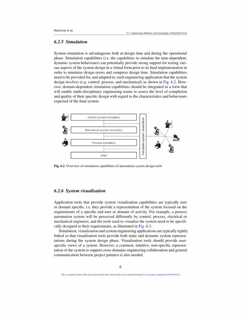
Application tools that provide system visualisation capabilities are typically useror domain specific, i.e. they provide a representation of the system focused on therequirements of a specific end user or domain of activity. For example, a processautomation system will be perceived differently by control, process, electrical ormechanical engineers, and the tools used to visualise the system need to be specifi-cally designed to their requirements, as illustrated in Fig. 6.3.
Simulation, visualisation and system engineering applications are typically tightlylinked so that visualisation tools provide both static and dynamic system represen-tations during the system design phase. Visualisation tools should provide user-specific views of a system. However, a common, intuitive, non-specific represen-tation of the system to support cross-domains engineering collaboration and generalcommunication between project partners is also needed.
6
This is a preprint version, which may deviate from the final version which can be acquired from https://www.springer.com/gp/book/9783319056234
Harrison et al.6.2. Engineering Methods and Cartography of Identified Tools
Fig. 6.3 Automation system Visualisation tool
3D computer graphic representations are typically used to implement commonvisualisation models of physical systems such as automation systems since a 3D vir-tual system representation provides a view of the system as perceived by the humanphysiological sensory system (i.e. sight) as opposed to the specific mental imagesthat various engineers might have of the system. Domain-specific system visualisa-tion tools might make use of very different representations (e.g. IEC 61131-3 forPLC control logic, state transition diagrams and Petri-net based representations fordiscrete system behaviour visualisation, and flow-based chart/graphs for continuoussystem visualisation).
6.2.7 System commissioning
The commissioning of a plant is a specific phase in the lifecycle. In this phase,the equipment, especially the field devices, will be installed and adapted to the realprocess requirements. Important tasks during commissioning include the identifica-tion of the devices, including the device type information, and setting the correctinstance information, e.g. the tag names of the devices. Commissioning may besubdivided into offline and online configuration activities. The offline configurationcan be started directly after the instrumentation is defined, capturing the types of therequired devices, their placement inside the plant and their addresses.
Functional information is required for device configuration. Typical technologiesproviding such information, for offline as well as online configuration, are the Elec-tronic Device Description Language (EDDL, IEC 61804-3)[22, 8], Field DeviceTool (FDT, IEC 62453) [7] or the upcoming approach of Field Device Integration(FDI).
7
This is a preprint version, which may deviate from the final version which can be acquired from https://www.springer.com/gp/book/9783319056234
Harrison et al.6.2. Engineering Methods and Cartography of Identified Tools
Fig. 6.4 Levels of Interoperability [2]
6.2.8 Interoperability
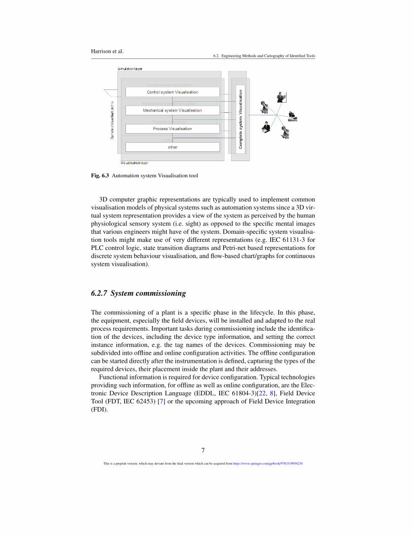
In order to build distributed control applications the components of a system needto communicate successfully. Engineering tools are required to support this integra-tion, and where direct interaction is not possible, then wrappers and mediators mustbe employed. Fig. 6.4 illustrates the levels of interoperability from no interoperabil-ity and technical interoperability at the network level through syntactic, semanticand pragmatic interoperability at the application level, to dynamic and conceptualinteroperability at the modelling level. Each of these is described below [2].
• Level 0: Stand-alone systems have No Interoperability.• Level 1: On the level of Technical Interoperability, a communication protocol
exists for exchanging data between participating systems. Here the communica-tion of simple data is achieved with the network protocols being unambiguouslydefined.
• Level 2: The Syntactic Interoperability level introduces a common structure toexchange information, i.e., a common data format is applied. On this level, acommon protocol to structure the data is used; the format of the informationexchange is unambiguously defined.
• Level 3: If a common information exchange reference model is used, the levelof Semantic Interoperability is reached. On this level, the meaning of the datais shared; the content of the information exchange requests are unambiguouslydefined.
8
This is a preprint version, which may deviate from the final version which can be acquired from https://www.springer.com/gp/book/9783319056234
Harrison et al.6.2. Engineering Methods and Cartography of Identified Tools
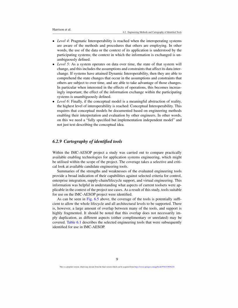
• Level 4: Pragmatic Interoperability is reached when the interoperating systemsare aware of the methods and procedures that others are employing. In otherwords, the use of the data or the context of its application is understood by theparticipating systems; the context in which the information is exchanged is un-ambiguously defined.
• Level 5: As a system operates on data over time, the state of that system willchange, and this includes the assumptions and constraints that affect its data inter-change. If systems have attained Dynamic Interoperability, then they are able tocomprehend the state changes that occur in the assumptions and constraints thatothers are subject to over time, and are able to take advantage of those changes.In particular when interested in the effects of operations, this becomes increas-ingly important; the effect of the information exchange within the participatingsystems is unambiguously defined.
• Level 6: Finally, if the conceptual model is a meaningful abstraction of reality,the highest level of interoperability is reached: Conceptual Interoperability. Thisrequires that conceptual models be documented based on engineering methodsenabling their interpretation and evaluation by other engineers. In other words,on this we need a “fully specified but implementation independent model” andnot just text describing the conceptual idea.
6.2.9 Cartography of identified tools
Within the IMC-AESOP project a study was carried out to compare practicallyavailable enabling technologies for application systems engineering, which mightbe utilised within the scope of the project. The coverage takes a selective and criti-cal look at available candidate engineering tools.
Summaries of the strengths and weaknesses of the evaluated engineering toolsprovide a broad indication of their capabilities against selected criteria for control,enterprise integration, supply-chain/lifecycle support, and virtual engineering. Thisinformation was helpful in understanding what aspects of current toolsets were ap-plicable in the context of the project use cases. As a result of this study, tools suitablefor use on the IMC-AESOP project were identified.
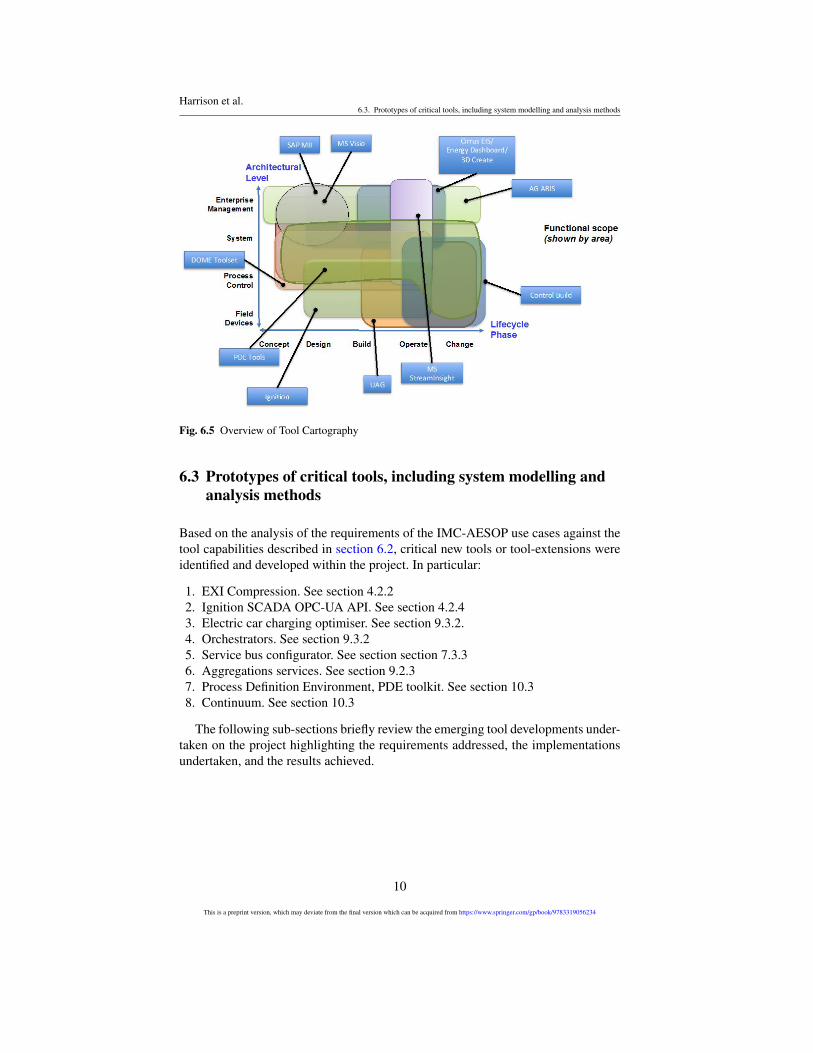
As can be seen in Fig. 6.5 above, the coverage of the tools is potentially suffi-cient to allow the whole lifecycle and all architectural levels to be supported. Thereis, however, a large amount of overlap between many of the tools, and support ishighly fragmented. It should be noted that this overlap does not necessarily im-ply duplication, as different aspects (either complimentary or unrelated) may becovered. Table 6.1 describes the selected engineering tools that were subsequentlyidentified for use in IMC-AESOP.
9
This is a preprint version, which may deviate from the final version which can be acquired from https://www.springer.com/gp/book/9783319056234
Harrison et al.6.3. Prototypes of critical tools, including system modelling and analysis methods
Fig. 6.5 Overview of Tool Cartography
6.3 Prototypes of critical tools, including system modelling andanalysis methods
Based on the analysis of the requirements of the IMC-AESOP use cases against thetool capabilities described in section 6.2, critical new tools or tool-extensions wereidentified and developed within the project. In particular:
1. EXI Compression. See section 4.2.22. Ignition SCADA OPC-UA API. See section 4.2.43. Electric car charging optimiser. See section 9.3.2.4. Orchestrators. See section 9.3.25. Service bus configurator. See section section 7.3.36. Aggregations services. See section 9.2.37. Process Definition Environment, PDE toolkit. See section 10.38. Continuum. See section 10.3
The following sub-sections briefly review the emerging tool developments under-taken on the project highlighting the requirements addressed, the implementationsundertaken, and the results achieved.
10
This is a preprint version, which may deviate from the final version which can be acquired from https://www.springer.com/gp/book/9783319056234
Harrison et al.6.3. Prototypes of critical tools, including system modelling and analysis methods
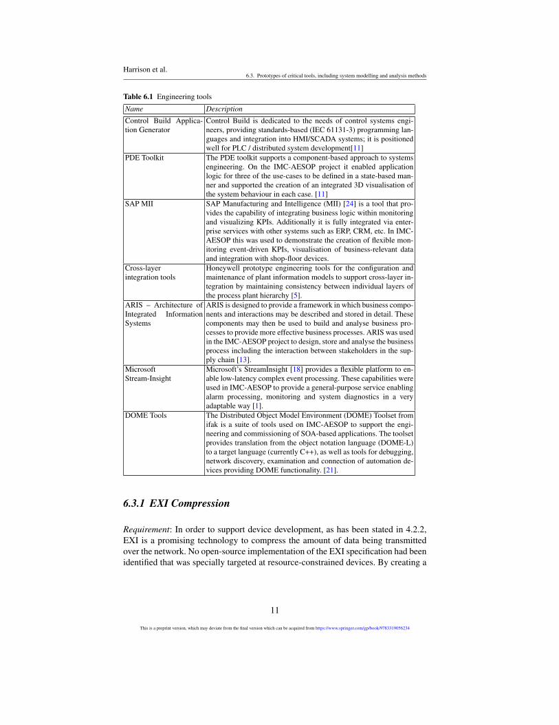
Table 6.1 Engineering tools
Name Description
Control Build Applica-tion Generator
Control Build is dedicated to the needs of control systems engi-neers, providing standards-based (IEC 61131-3) programming lan-guages and integration into HMI/SCADA systems; it is positionedwell for PLC / distributed system development[11]
PDE Toolkit The PDE toolkit supports a component-based approach to systemsengineering. On the IMC-AESOP project it enabled applicationlogic for three of the use-cases to be defined in a state-based man-ner and supported the creation of an integrated 3D visualisation ofthe system behaviour in each case. [11]
SAP MII SAP Manufacturing and Intelligence (MII) [24] is a tool that pro-vides the capability of integrating business logic within monitoringand visualizing KPIs. Additionally it is fully integrated via enter-prise services with other systems such as ERP, CRM, etc. In IMC-AESOP this was used to demonstrate the creation of flexible mon-itoring event-driven KPIs, visualisation of business-relevant dataand integration with shop-floor devices.
Cross-layerintegration tools
Honeywell prototype engineering tools for the configuration andmaintenance of plant information models to support cross-layer in-tegration by maintaining consistency between individual layers ofthe process plant hierarchy [5].
ARIS – Architecture ofIntegrated InformationSystems
ARIS is designed to provide a framework in which business compo-nents and interactions may be described and stored in detail. Thesecomponents may then be used to build and analyse business pro-cesses to provide more effective business processes. ARIS was usedin the IMC-AESOP project to design, store and analyse the businessprocess including the interaction between stakeholders in the sup-ply chain [13].
MicrosoftStream-Insight
Microsoft’s StreamInsight [18] provides a flexible platform to en-able low-latency complex event processing. These capabilities wereused in IMC-AESOP to provide a general-purpose service enablingalarm processing, monitoring and system diagnostics in a veryadaptable way [1].
DOME Tools The Distributed Object Model Environment (DOME) Toolset fromifak is a suite of tools used on IMC-AESOP to support the engi-neering and commissioning of SOA-based applications. The toolsetprovides translation from the object notation language (DOME-L)to a target language (currently C++), as well as tools for debugging,network discovery, examination and connection of automation de-vices providing DOME functionality. [21].
6.3.1 EXI Compression
Requirement: In order to support device development, as has been stated in 4.2.2,EXI is a promising technology to compress the amount of data being transmittedover the network. No open-source implementation of the EXI specification had beenidentified that was specially targeted at resource-constrained devices. By creating a
11
This is a preprint version, which may deviate from the final version which can be acquired from https://www.springer.com/gp/book/9783319056234
Harrison et al.6.3. Prototypes of critical tools, including system modelling and analysis methods
suitable tool, it was possible to encode up to ten times smaller standard servicemessages (XML) on extreme resource-constrained sensor and actuator devices.
Implementation Description and Use: The tool was developed from scratch usinga modular design and portable source code. The tool was used extensively duringthe IMC-AESOP demonstrations related to the LKAB ore processing and districtheating application use-cases for implementing light-weight SOAP and RESTfulWeb services.
Results: The developed tool is open source (exip.sourceforge.net), has beendownloaded more than 1600 times, and is already being used in projects outsideIMC-AESOP. The current version of the tool is in alpha form, and there is a needfor more testing to make the code stable enough for production use. The tool comeswith both user- and developer-documentation that is up to date and in use by con-tributors and end-users alike.
6.3.2 Ignition SCADA OPC-UA API
Requirement: As described in 4.2.4 OPC-UA is a widely accepted standard for pro-viding interoperability between devices and systems. For the IMC-AESOP projectIgnition SCADA was the chosen SCADA solution which supports OPC-UA. To in-tegrate Ignition SCADA with DPWS an OPC-UA API was be created. Ignition isan industrial application server from Inductive Automation [9], used to create HMI,SCADA, and MES systems. Ignition (formerly FactorySQL and FactoryPMI) is amature and well-tested application. The feature list includes:
• Web-based gateway configuration and HMI drag-and-drop editor.• A rich set of visual components free for end-users.• Database-centric architecture.• Advanced reporting and alerting mechanisms.• Designed from the ground-up for scalability.• Implemented in Java, so it can be run on a wide range of platforms, on all major
operating systems.• Control system access on mobile device.
State-of-the-art SCADA systems are capable of supporting almost any industrialcommunication protocol, such as Modbus, Profibus and DeviceNet. In the case ofDPWS embedded devices, however, such support does not currently exist. It wastherefore necessary to develop a SCADA plug-in that would enable this functional-ity in a commercial SCADA system, in this case the Inductive Automation Ignitionsystem.
Implementation Description and Use: A new gateway module was created onIMC-AESOP containing a DPWS client stack. This client stack will discover DPWSdevices and create representations of the devices as nodes in the OPC-UA AddressSpace. Any OPC-UA client connecting to the Ignition OPC-UA server must be able
12
This is a preprint version, which may deviate from the final version which can be acquired from https://www.springer.com/gp/book/9783319056234
Harrison et al.6.3. Prototypes of critical tools, including system modelling and analysis methods
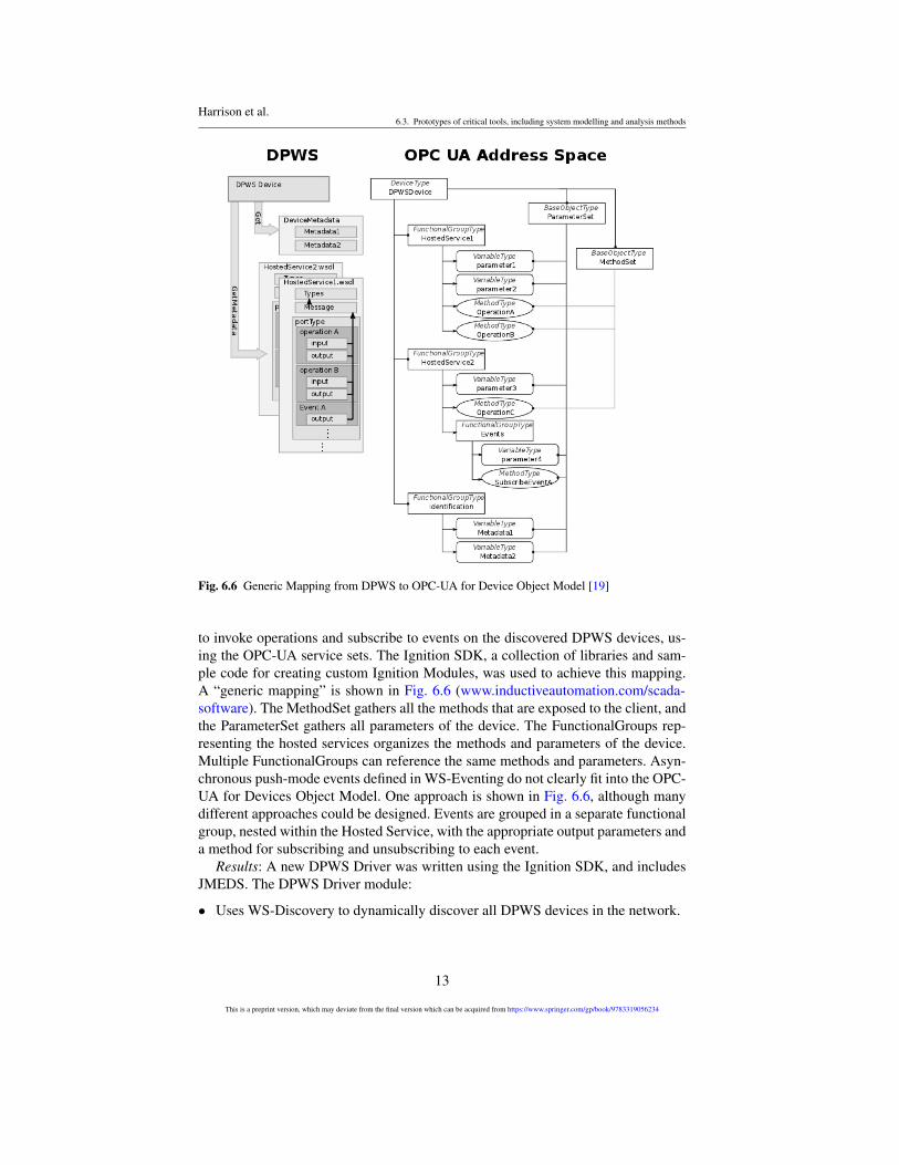
Fig. 6.6 Generic Mapping from DPWS to OPC-UA for Device Object Model [19]
to invoke operations and subscribe to events on the discovered DPWS devices, us-ing the OPC-UA service sets. The Ignition SDK, a collection of libraries and sam-ple code for creating custom Ignition Modules, was used to achieve this mapping.A “generic mapping” is shown in Fig. 6.6 (www.inductiveautomation.com/scada-software). The MethodSet gathers all the methods that are exposed to the client, andthe ParameterSet gathers all parameters of the device. The FunctionalGroups rep-resenting the hosted services organizes the methods and parameters of the device.Multiple FunctionalGroups can reference the same methods and parameters. Asyn-chronous push-mode events defined in WS-Eventing do not clearly fit into the OPC-UA for Devices Object Model. One approach is shown in Fig. 6.6, although manydifferent approaches could be designed. Events are grouped in a separate functionalgroup, nested within the Hosted Service, with the appropriate output parameters anda method for subscribing and unsubscribing to each event.
Results: A new DPWS Driver was written using the Ignition SDK, and includesJMEDS. The DPWS Driver module:
• Uses WS-Discovery to dynamically discover all DPWS devices in the network.
13
This is a preprint version, which may deviate from the final version which can be acquired from https://www.springer.com/gp/book/9783319056234
Harrison et al.6.3. Prototypes of critical tools, including system modelling and analysis methods
• Creates, manages, updates, and deletes representations of the devices in the OPC-UA Address Space and in the Ignition SQLTags system and maintains consis-tency between the two representations.
• Connects the actual device with its representation in the OPC-UA Address Space.• Handles communication with the discovered devices, including subscription
management, receiving events, and operation invocations and responses.
6.3.3 Electric car charging optimiser
Requirement: The requirement for optimisation of electric car charging is that ex-cess energy from the power plant be used in order to charge electric cars in a cost-optimized way. Here the requirement is to build an optimized scheduling of thecharging of electric cars in order to adhere to constraints set (e.g., the available en-ergy, electricity price, minimum electric car charging requirements). To do so, aservice has been developed that tries to charge all electric vehicles to specified en-ergy levels within a limited timeframe (i.e., by the car’s expected departure time),while trying to exploit fluctuating electricity costs and respecting maximum powerlimits.
Implementation Description and Use: The orchestrator brings together the fol-lowing systems:
1. Plant simulator2. Electric Car Optimizer (running in the SAP HANA Cloud)3. Energy Market (running as an Internet public service)
The service has been implemented in Java and runs in the SAP HANA Cloud [23].It is called by the orchestrator, which transmits data about the available cars, theirrequirements and their needs, as well as information about the power plant’s energyproduction limits and costs. The interface is implemented as a set of REST services.
Results: The electric car charging optimiser could play a crucial role in thesmoothing out of power consumption and making energy production more efficient.It was shown that a cloud service providing this functionality is viable and can em-power more sophisticated scenarios. Additional info can be found in Chapter 9.
6.3.4 Orchestrators
Requirement: An application (Matlab/Simulink) has been used in order to simulatethe power plant itself as well as the cars that get charged. As this is currently a privatesimulation and not a public service, an “orchestrator” is required to act as the gluebetween the three different systems. Further to this, the Orchestrator also hosts thelogic for contacting the energy bidding agent and passing it all the necessary datafor acting in the energy market.
14
This is a preprint version, which may deviate from the final version which can be acquired from https://www.springer.com/gp/book/9783319056234
Harrison et al.6.3. Prototypes of critical tools, including system modelling and analysis methods
Implementation Description and Use: The orchestrator logically integrates thePlant Simulator with the Electric Car Optimizer running in the SAP HANA Cloud,and the Energy Market that runs as an Internet public service [10].
Results: The implemented orchestrator plays a crucial role:
1. In acting as a mediator between the different technologies, e.g., between OPC-UA and REST.
2. As a management point during the whole lifecycle of the simulated scenario.3. As an instrument to collect real time data for date collection and analysis.
Additional info can be found in Chapter 9.
6.3.5 Service bus configurator
Requirement: The Distributed Service Bus middleware applied on IMC-AESOP re-quired some configuration and monitoring capability. The identified needs included:
1. Monitoring of discovered Service Bus nodes and managed devices.2. Enabling/ disabling specific interfaces.3. Security configuration (Role Based Access Control).4. Management of Service Bus built-in services, including time synchronisation.
In order to facilitate the deployment and maintenance of this tool, a Web clientsolution, served by one or several Service Bus bricks, was preferred.
Implementation Description and Use: The Configurator has been implementedas a Web application, using the popular Google Web Toolkit development frame-work. This framework allows developers to write the client application in the Javalanguage and then convert it to AJAX (Asynchronous JavaScript).
Results: The implementation proved to be successful, providing a stable and ef-ficient tool to monitor the Distributed Service Bus, and it has been demonstrated inthe lubrication application of use case 1. The Configurator tool was used, in particu-lar, to manage time synchronisation between the Service Bus and other demonstratorcomponents (Mediator and CoAP), monitor managed devices (AS-I and CoAP), andmonitor the LKAB application logic that was running on the Service Bus itself.
6.3.6 Aggregation services
Requirement: The orchestration of services is a core concept in Service-Oriented Ar-chitectures (SOA). This is basically about creating new, added-value services out ofexisting services and is a concept that was established from the beginning of SOA.There are a number of specifications available to assist in the composition of ser-vices. The most prominent one is probably WS-BPEL[20]. Others either deal withthe orchestration or choreography of services. Within IMC-AESOP the focus was
15
This is a preprint version, which may deviate from the final version which can be acquired from https://www.springer.com/gp/book/9783319056234
Harrison et al.6.3. Prototypes of critical tools, including system modelling and analysis methods
on providing a service or a tool for helping in the real-time analysis of a large num-ber of events from multiple sources. In this case the service that processes data is aComplex Event Processing (CEP) service. Currently, services are being deployed atdevice level, such in the Internet of Things, which is advocated by the IMC-AESOPproject. These services may be considered as data services providing a continuousstream of data. The CEP service may be regarded as an event broker with analyticscapabilities and with the ability to connect stack services, making it possible to:
1. Define the flow of events (data) by topics.2. Define queries (analytics) processing incoming data by topic.3. Define consumers of events by topics.
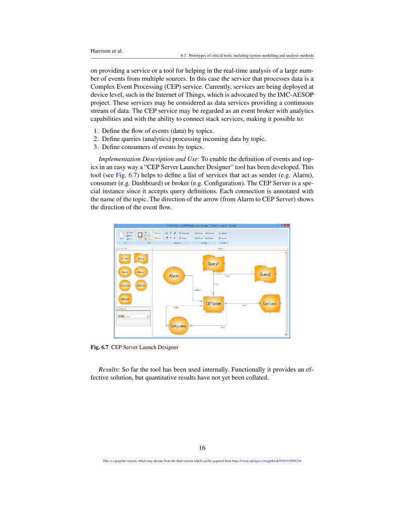
Implementation Description and Use: To enable the definition of events and top-ics in an easy way a “CEP Server Launcher Designer” tool has been developed. Thistool (see Fig. 6.7) helps to define a list of services that act as sender (e.g. Alarm),consumer (e.g. Dashboard) or broker (e.g. Configuration). The CEP Server is a spe-cial instance since it accepts query definitions. Each connection is annotated withthe name of the topic. The direction of the arrow (from Alarm to CEP Server) showsthe direction of the event flow.
Fig. 6.7 CEP Server Launch Designer
Results: So far the tool has been used internally. Functionally it provides an ef-fective solution, but quantitative results have not yet been collated.
16
This is a preprint version, which may deviate from the final version which can be acquired from https://www.springer.com/gp/book/9783319056234

Harrison et al.6.3. Prototypes of critical tools, including system modelling and analysis methods
6.3.7 Process Definition Environment, PDE toolkit
Requirement: The IMC-AESOP project requires the building and integration ofapplication-related services across a range of systems. The Process Definition Envi-ronment (PDE) enables the definition of relationships between system componentsin support of orchestration or choreography. The PDE toolkit enables systems com-posed of many logically interlocked components to be visualized and validated.
Fig. 6.8 Process Definition Environment (PDE)
Implementation Description and Use: On the IMC-AESOP project the PDEtoolkit was used to validate and visualize Use Cases 1 and 4 for lubrication andbuilding systems, respectively [11]. This is illustrated in Fig. 6.8. Routing logic de-fined within the PDE toolset enables the material or product flow in the system tobe simulated. This in conjunction with a simulation engine enables each applicationto be observed and validated. The state-based components within the system canbe stored in a library with their associated 3D visualisations. The PDE toolkit [12]employs a simulation engine that requires the definition of how the outside world(e.g., product or process parts) interacts with the machinery. This process knowl-edge, typically defined by a process engineer, is entered into a routing, which inturn drives the input of the sensors in the simulation, which drives the applicationto react to fulfil the desired logic. Once the control has been validated, it can poten-tially be downloaded to orchestration engines on a range of SOA devices; however,
17
This is a preprint version, which may deviate from the final version which can be acquired from https://www.springer.com/gp/book/9783319056234
Harrison et al.6.3. Prototypes of critical tools, including system modelling and analysis methods
this phase was beyond the scope of IMC-AESOP although it is a major objectivefor future work. The PDE tool supports the deployment of the application logic toorchestrators at potentially any level in the target architecture on a range of targetdevices.
Results: The PDE toolkit has been successfully used to simulate the behaviourof components in the lubrication application of Use Case 1 and verify the behaviourof the district heating system in Use Case 4 as depicted in Chapter 10. Break pointshave allowed the scenarios defined in these use cases to be quickly evaluated. Theinclusion of processes has created the ability to “manage” the automation systemusing the high-level process view. This results in the control system being easier tounderstand from a maintenance point of view and in the case of Use Case 4 providesthe ability to run different processes based upon external factors, such as long-rangeweather forecasts.
6.3.8 Continuum
Requirement: With the Continuum tool [17] it was possible to create very large con-trol and monitoring structures by using the formal method “High-level Petri Nets”(HLPN). Related to the HLPN theory there are a range of analysis and validationpossibilities. The Continuum tool provided a lot of these important functionalities.Based on analysis and validation results, calculated from the tool, it was much eas-ier to introduce the simulation of complex monitoring and control systems in thenext step. The start of the implementation of the Continuum tool was in the EU FP6SOCRADES project where the first control structures were built with this tool. Inthis project the Continuum tool helped to solve the challenge to design very complexcontrol structures for very large control and monitoring systems in a rapid manner.
Implementation Description and Use: The performance challenge was solved byparallelising the algorithms and by using GPUs for the new algorithm design. Thecompany NVIDIA provides a framework called CUDA for parallel programmingneeds, which was used for the parallelisation. The performance of the Continuumtool is now growing with the increasing performance of NVIDIA GPU technologies.
Results: With support from this tool it was possible to generate monitoring andcontrol structures in a very fast way for very large systems. Continuum is a powerfulprototype tool with the potential to be extended in the future to a mature engineeringtool. First publications are available describing a graphical engineering interface andmethod that will provide a very easy engineering method. The approach is simpleto apply even to very complex control and monitoring structures in a system-of-systems paradigm, with automatic support for analysis and validation by the tool.
18
This is a preprint version, which may deviate from the final version which can be acquired from https://www.springer.com/gp/book/9783319056234
Harrison et al.6.4. Engineering Toolkit Application to Use Cases
6.4 Engineering Toolkit Application to Use Cases
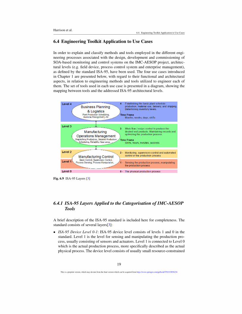
In order to explain and classify methods and tools employed in the different engi-neering processes associated with the design, development and commissioning ofSOA-based monitoring and control systems on the IMC-AESOP project, architec-tural levels (e.g. field device, process control system and enterprise management),as defined by the standard ISA-95, have been used. The four use cases introducedin Chapter 1 are presented below, with regard to their functional and architecturalaspects, in relation to engineering methods and tools utilized to engineer each ofthem. The set of tools used in each use case is presented in a diagram, showing themapping between tools and the addressed ISA-95 architectural levels.
Fig. 6.9 ISA-95 Layers [3]
6.4.1 ISA-95 Layers Applied to the Categorisation of IMC-AESOPTools
A brief description of the ISA-95 standard is included here for completeness. Thestandard consists of several layers[3]:
• ISA-95 Device Level 0-1: ISA-95 device level consists of levels 1 and 0 in thestandard. Level 1 is the level for sensing and manipulating the production pro-cess, usually consisting of sensors and actuators. Level 1 is connected to Level 0which is the actual production process, more specifically described as the actualphysical process. The device level consists of usually small resource-constrained
19
This is a preprint version, which may deviate from the final version which can be acquired from https://www.springer.com/gp/book/9783319056234
Harrison et al.6.4. Engineering Toolkit Application to Use Cases
devices that link the service architecture to the production process. The impor-tance of a semantic Web service approach at the device level can be found in[14]
• ISA-95 Control/ SCADA Level 2: In general terms this level is concerned with thecontrol and visibility of production processes. This does not include the real timecontrol of processing equipment, which is the concern of Level 1, but chieflythe integration, e.g., the orchestration or choreography of devices, in the Level 1controllers to achieve specific tasks related to recipes or production objectives.This may be in the form of either orchestration or choreography of devices (e.g.,in discrete manufacturing), or supervisory multivariable control of the steadystate operation (e.g., in the continuous process industry).
• ISA-95 MES Level 3: Manufacturing Execution System (MES) is referred to asLevel 3 in the ISA-95 standard. The MES level handles workflow and recipes,among other things, in order to produce the desired products.
• ISA-95 ERP Level 4: ISA-95 is a standard developed to address the interface be-tween enterprise and control systems. More specifically, it addresses integrationwith the production/MES layer as well as B2M transactions. Level 4 as describedin ISA-95 deals with business planning and logistics, including plant produc-tion scheduling and operational management. The timeframe here could be days,weeks, months or shifts, considerably longer than at the other lower levels.
The discussion now moves to focus on the different use-cases and the mappingof tools to these layers.
6.4.2 Use Case 1: Migration of a Legacy Plant Lubrication Systemto SOA
The objective of use case 1 was to demonstrate the migration of an existing lubri-cation system in an industrial process plant to the IMC-AESOP architecture. Lubri-cation systems represent one of the most important types of support systems seenin such industries. Although such lubrication systems are critical for good perfor-mance, they are often implemented as black-boxes with limited system integration.
The tools utilized to engineer the migration of the plant lubrication system toSOA are described below.
• C compiler (GCC): A compiler is required to translate the human readable sourcecode into binary code for processors and microcontrollers. The Mulle moduleuses a Renesas M16C microcontroller. The GNU Compiler Collection consistsof a C and several other compilers. GCC supports many different developmentand target systems. With cross compiling it is possible to develop software on anordinary PC and compile it to a completely different system e.g. running on anx86 PC.
• Timber: Timber is a functional programming language derived from Haskell.Timber is event driven using reactive objects. The compiler compiles from Tim-
20
This is a preprint version, which may deviate from the final version which can be acquired from https://www.springer.com/gp/book/9783319056234
Harrison et al.6.4. Engineering Toolkit Application to Use Cases
ber to intermediate C code that is parsed to GCC. Other intermediate optionslike Low Level Virtual Machine (LLVM) are investigated by other organisations.Earlier versions of Timber were interpreted.
• Flasher: Flasher is a software kit to program flash memories on the Mulle mod-ule. Mulle uses a Renesas M16C microcontroller connected to external flashmemories.
• CoAP/EXI: CoAP can support several transfer methods, ranging from humanreadable XML to more efficient binary methods. In order to enable efficient XMLInterchange, EXI has been chosen for this use case due to several performanceadvantages, such as reduced memory footprint and shorter packets that are morelikely to fit in a single (radio) frame. For embedded devices and sensors in partic-ular memory resources are often scarce. Fewer radio frames increase reliabilityand battery life.
• SOA4D DPWS Toolkit: One of the major results of recent R&D projects likeITEA2 SIRENA and European FP6 SOCRADES has been a DPWS implemen-tation called SOA for Devices (www.soa4d.org). This implementation has beenfurther improved for the IMC-AESOP approach and used in this use case. Specif-ically, the SOA4D toolkit is utilized to implement the DPWS support in the ser-vice bus, both for the communication with a mediator component and for thecommunication with a Smart Meter Emulator.
• Smart Meter Emulator: A simulator for the energy-related aspects of devices tar-geting smart metering and costs has been developed. It gives the possibility tointeract via DPWS and REST with the devices and additionally supports devicelifecycle management (e.g., for start/stop/add/remove) of any device, flexible de-scription of classes of devices and their behaviour (done in XML configuration),adjustment of energy prices that are used for operational cost calculation, andsupport for automated creation of a large number of devices to ease tests (donevia XML configuration).
• TinyOS: TinyOS is designed for low-power wireless devices like Mulle. TinyOSpartially supports IPv6 and CoAP. UDP is supported with TCP in prototype form.For CoAP GET & PUT methods are supported, but neither POST nor DELETEare supported.
• Mozilla Copper plug-in: This plug-in provides a handler for the “CoAP” URIscheme to Mozilla Firefox. With this plug-in capability Firefox can be used fortroubleshooting and for some configuration during commissioning.
• Service Bus Configurator: The Service Bus middleware is intended to run onindustrial embedded devices. Such devices typically have very limited HMI ca-pabilities. The Service Bus however needs some means for its configuration andmonitoring. This has been achieved through a Web-based application hosted oneach device, called a Service Bus Configurator. This application relies on RichInteLTUrnet Application concepts and has been written using the Google WebToolkit software development kit. The Configurator application is downloadedfrom any device hosting the Service Bus into a Web browser running on a com-puter connected to this device. Communication between the Configurator and the
21
This is a preprint version, which may deviate from the final version which can be acquired from https://www.springer.com/gp/book/9783319056234
Harrison et al.6.4. Engineering Toolkit Application to Use Cases
Service Bus is based on RESTful Web services. Features that can be configured/-monitored using the Service Bus Configurator include:
– Adding a new device to the Service Bus (e.g., CoAP edge router and AS-igateway . . . )
– Monitoring devices/services composing the Service Bus (status, configurationparameters . . . )
– Configuring/monitoring event broker topics and subscriptions– Service Bus system events
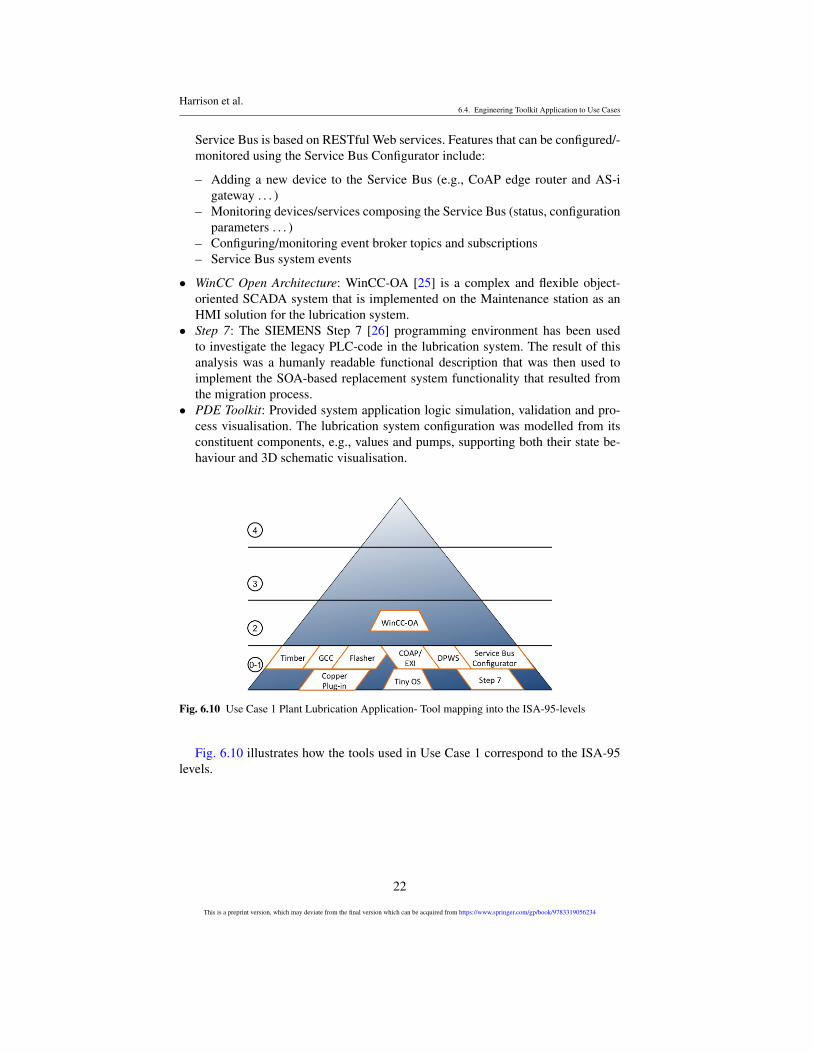
• WinCC Open Architecture: WinCC-OA [25] is a complex and flexible object-oriented SCADA system that is implemented on the Maintenance station as anHMI solution for the lubrication system.
• Step 7: The SIEMENS Step 7 [26] programming environment has been usedto investigate the legacy PLC-code in the lubrication system. The result of thisanalysis was a humanly readable functional description that was then used toimplement the SOA-based replacement system functionality that resulted fromthe migration process.
• PDE Toolkit: Provided system application logic simulation, validation and pro-cess visualisation. The lubrication system configuration was modelled from itsconstituent components, e.g., values and pumps, supporting both their state be-haviour and 3D schematic visualisation.
Fig. 6.10 Use Case 1 Plant Lubrication Application- Tool mapping into the ISA-95-levels
Fig. 6.10 illustrates how the tools used in Use Case 1 correspond to the ISA-95levels.
22
This is a preprint version, which may deviate from the final version which can be acquired from https://www.springer.com/gp/book/9783319056234
Harrison et al.6.4. Engineering Toolkit Application to Use Cases
6.4.3 Use Case 2: Implementing Circulating Oil LubricationSystems based on the IMC-AESOP Architecture
Oil lubrication systems are commonly used in paper machines where hundreds oflubrication points are needed. In general, for the implementation of this use casetwo different types of tools were used:
1. Development and Deployment tools were used to create, program and configurethe necessary behaviours and functions of the use case.
2. Testing tools used to test the developed and deployed system.
Development tools used:
• Apache ServiceMix: A platform providing useful functionality for integratingtechnologies internal to components, and WS frameworks for exposing services.
• Apache Camel: An open source integration framework based on enterprise inte-gration patterns, which provides connectivity to a wide array of technologies/-transports/protocols/APIs, included in ServiceMix.
• Jetty: A simple HTTP server, which can be used for consuming and producingHTTP requests.
• WS4D-JMEDS (Web services for Devices – Java Multi-Edition DPWS Stack):An open-source stack for developing DPWS clients, devices, and services.
• JAX-WS: (Java API for XML Web services) A Java API for developing Webservices.
• WCF (Windows Communication Foundation): Windows runtime API for devel-oping SOA applications in C#.
• StreamInsight:A platform for developing and deploying CEP applications fromMicrosoft
• Ignition Server: A commercial HMI/SCADA system with integrated OPC-UAserver.
• Ignition Developer API: An application programming interface for developingcustom modules for the Ignition Gateway, Designer, or Client in Eclipse.
• Eclipse BPEL Designer: A graphical editor for creating BPEL processes.• Orchestration Engine: A tool developed for executing WS-BPEL processes.
Testing tools used:
• WCFStormLite: For testing WCF Services.• DPWS Explorer: For testing services on DPWS devices.• UA Expert: A free OPC-UA Client for testing OPC-UA and DPWS integration.
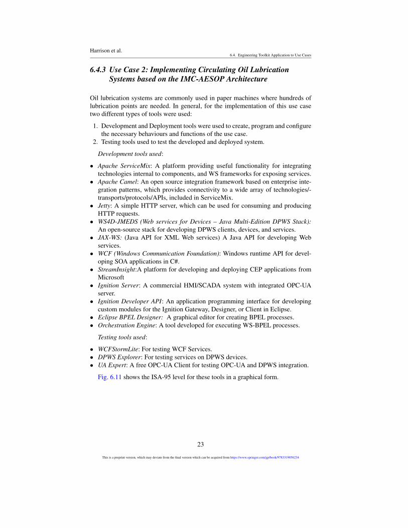
Fig. 6.11 shows the ISA-95 level for these tools in a graphical form.
23
This is a preprint version, which may deviate from the final version which can be acquired from https://www.springer.com/gp/book/9783319056234
Harrison et al.6.4. Engineering Toolkit Application to Use Cases
Fig. 6.11 Use Case 2 Circulating Oil Lubrication Application- Tool mapping into the ISA-95-levels
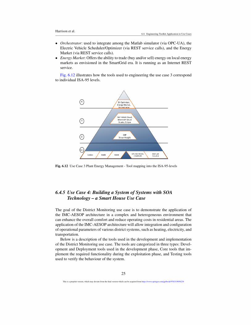
6.4.4 Use Case 3: Plant Energy Management
The main objective of this use case 3 was to highlight advantages of service ori-entation, event-driven processing and semantics for easier configuration, dynamicsynchronisation and maintenance of complicated multi-layer solutions, which areneeded today in continuous process plants.
Tools used:
• Matlab Simulink: multi-purpose dynamic simulation environment, which wasused for development of the power plant dynamic model.
• Honeywell UniSim: proprietary simulation environment for development, valida-tion and real-time execution of dynamic process models.
• Honeywell Profit Suite: a framework with a set of proprietary tools for develop-ment, configuration, and deployment of control applications.
• Microsoft StreamInsight: a framework for implementation of Complex EventProcessing applications.
• Eclipse for JAVA implementation and Microsoft Visual Studio for C++ imple-mentation.
• Information model building tools: Address Space Model De-signer (ASMD),XML editor and OPC-UA Model Compiler. tools were used to create the OPC-UA address space. This includes nodes, attributes and their mutual relationships.
• The data binding tool: for binding of the data items inside a server address spaceto external data sources.
• Information model configuration tool: for the chained Level 2 servers where itallows to create an instance of a sub-system and define device, topology, andbinding views.
• Electric Vehicle Scheduler/Optimizer: schedules in a optimal way (under con-straints) the electric cars of the company. It is implemented as a cloud service(REST) based on SAP HANA Cloud.
24
This is a preprint version, which may deviate from the final version which can be acquired from https://www.springer.com/gp/book/9783319056234
Harrison et al.6.4. Engineering Toolkit Application to Use Cases
• Orchestrator: used to integrate among the Matlab simulator (via OPC-UA), theElectric Vehicle Scheduler/Optimizer (via REST service calls), and the EnergyMarket (via REST service calls).
• Energy Market: Offers the ability to trade (buy and/or sell) energy on local energymarkets as envisioned in the SmartGrid era. It is running as an Internet RESTservice.
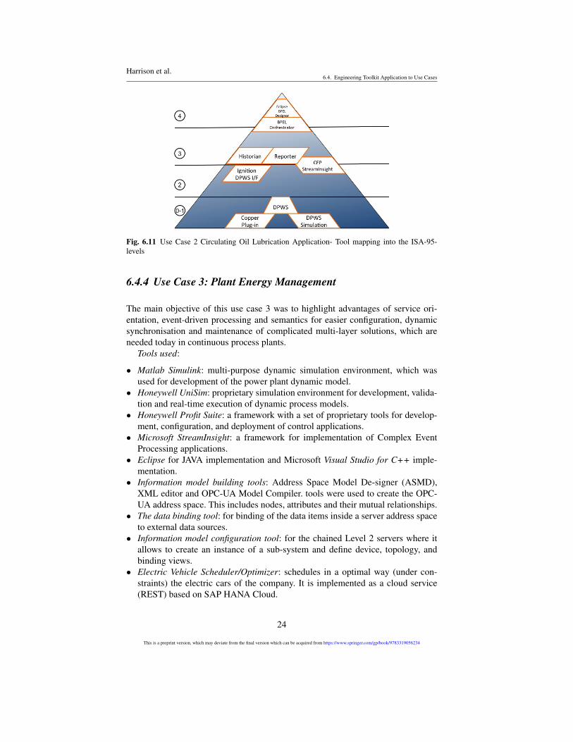
Fig. 6.12 illustrates how the tools used to engineering the use case 3 correspondto individual ISA-95 levels.
Fig. 6.12 Use Case 3 Plant Energy Management - Tool mapping into the ISA-95-levels
6.4.5 Use Case 4: Building a System of Systems with SOATechnology – a Smart House Use Case
The goal of the District Monitoring use case is to demonstrate the application ofthe IMC-AESOP architecture in a complex and heterogeneous environment thatcan enhance the overall comfort and reduce operating costs in residential areas. Theapplication of the IMC-AESOP architecture will allow integration and configurationof operational parameters of various district systems, such as heating, electricity, andtransportation.
Below is a description of the tools used in the development and implementationof the District Monitoring use case. The tools are categorized in three types: Devel-opment and Deployment tools used in the development phase, Core tools that im-plement the required functionality during the exploitation phase, and Testing toolsused to verify the behaviour of the system.
25
This is a preprint version, which may deviate from the final version which can be acquired from https://www.springer.com/gp/book/9783319056234
Harrison et al.6.4. Engineering Toolkit Application to Use Cases
Tools used:
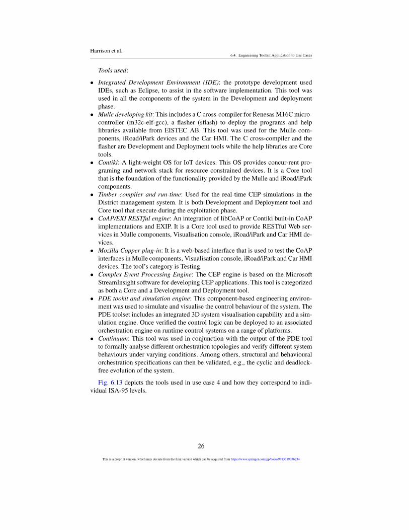
• Integrated Development Environment (IDE): the prototype development usedIDEs, such as Eclipse, to assist in the software implementation. This tool wasused in all the components of the system in the Development and deploymentphase.
• Mulle developing kit: This includes a C cross-compiler for Renesas M16C micro-controller (m32c-elf-gcc), a flasher (sflash) to deploy the programs and helplibraries available from EISTEC AB. This tool was used for the Mulle com-ponents, iRoad/iPark devices and the Car HMI. The C cross-compiler and theflasher are Development and Deployment tools while the help libraries are Coretools.
• Contiki: A light-weight OS for IoT devices. This OS provides concur-rent pro-graming and network stack for resource constrained devices. It is a Core toolthat is the foundation of the functionality provided by the Mulle and iRoad/iParkcomponents.
• Timber compiler and run-time: Used for the real-time CEP simulations in theDistrict management system. It is both Development and Deployment tool andCore tool that execute during the exploitation phase.
• CoAP/EXI RESTful engine: An integration of libCoAP or Contiki built-in CoAPimplementations and EXIP. It is a Core tool used to provide RESTful Web ser-vices in Mulle components, Visualisation console, iRoad/iPark and Car HMI de-vices.
• Mozilla Copper plug-in: It is a web-based interface that is used to test the CoAPinterfaces in Mulle components, Visualisation console, iRoad/iPark and Car HMIdevices. The tool’s category is Testing.
• Complex Event Processing Engine: The CEP engine is based on the MicrosoftStreamInsight software for developing CEP applications. This tool is categorizedas both a Core and a Development and Deployment tool.
• PDE tookit and simulation engine: This component-based engineering environ-ment was used to simulate and visualise the control behaviour of the system. ThePDE toolset includes an integrated 3D system visualisation capability and a sim-ulation engine. Once verified the control logic can be deployed to an associatedorchestration engine on runtime control systems on a range of platforms.
• Continuum: This tool was used in conjunction with the output of the PDE toolto formally analyse different orchestration topologies and verify different systembehaviours under varying conditions. Among others, structural and behaviouralorchestration specifications can then be validated, e.g., the cyclic and deadlock-free evolution of the system.
Fig. 6.13 depicts the tools used in use case 4 and how they correspond to indi-vidual ISA-95 levels.
26
This is a preprint version, which may deviate from the final version which can be acquired from https://www.springer.com/gp/book/9783319056234
Harrison et al.6.5. Conclusions
Fig. 6.13 Use Case 4 Building System of Systems with SOA Technology – a Smart House – Toolmapping into the ISA-95-levels
6.5 Conclusions
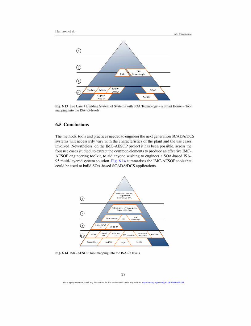
The methods, tools and practices needed to engineer the next generation SCADA/DCSsystems will necessarily vary with the characteristics of the plant and the use casesinvolved. Nevertheless, on the IMC-AESOP project it has been possible, across thefour use cases studied, to extract the common elements to produce an effective IMC-AESOP engineering toolkit, to aid anyone wishing to engineer a SOA-based ISA-95 multi-layered system solution. Fig. 6.14 summarises the IMC-AESOP tools thatcould be used to build SOA-based SCADA/DCS applications.
Fig. 6.14 IMC-AESOP Tool mapping into the ISA-95 levels
27
This is a preprint version, which may deviate from the final version which can be acquired from https://www.springer.com/gp/book/9783319056234
Harrison et al.References
Device level support can be provided by CoAP and EXI, using the service busconfigurator for integration of devices built using development tools such as Timberand the Mulle development kit, which are deployed on devices running FreeRTOS,TinyOS and Contiki.
SCADA functionality can be provided by Ignition and WinCC-OA using the pro-totype OPC-UA interface for integration with the devices, whilst system modelling,simulation and visualisation is supported by the PDE toolkit for simulation and Con-tinuum for verification. The HANA Cloud is used to provide manufacturing execu-tion system functionality.
The enterprise level tools highlighted by IMC-AESOP are the Eclipse BPEL de-signer and a BPEL orchestrator to execute them. Finally Microsoft’s StreamInsighthas been employed for the aggregation and processing of events generated by largescale systems as well as for integration of disparate systems, as part of a system-of-systems approach.
The combined use of these tools allows the engineering of complete applicationsin which components from any level of the ISA-95 can be integrated to provide acoherent SOA-based SCADA/DCS solution, such as the ones described in Chapters7-10.
Acknowledgment
The authors would like to thank the European Commission for their support, and thepartners of the EU FP7 project IMC-AESOP (www.imc-aesop.eu) for the fruitfuldiscussions.
References
[1] Ali M, Chandramouli B, Goldstein J, Schindlauer R (2011) The extensibil-ity framework in microsoft streaminsight. In: Data Engineering (ICDE), 2011IEEE 27th International Conference on, pp 1242–1253, DOI 10.1109/ICDE.2011.5767878
[2] Andreas T, Saikou D, Charles T (2007) Applying the levels of conceptual in-teroperability model in support of integratability, interoperability, and compos-ability for system-of-systems engineering. Journal of Systemics, Cyberneticsand Informatics
[3] Brandl D, Consulting B (2008) What is ISA-95? Industrial Best Practices ofManufacturing Information Technologies with ISA-95 Models
[4] Chawla R, Banerjee A (2001) A virtual environment for simulating manufac-turing operations in 3D. In: Winter Simulation Conference, pp 991–997, DOI10.1145/564124.564265, URL http://dblp.uni-trier.de/db/conf/wsc/wsc2001.html#ChawlaB01
28
This is a preprint version, which may deviate from the final version which can be acquired from https://www.springer.com/gp/book/9783319056234
Harrison et al.References
[5] CommSrv (2013) Address space model designer. URL http://www.commsvr.com/Products/OPCUA/UAModelDesigner.aspx
[6] Dai W, Vyatkin V (2010) Redesign distributed iec 61131-3 plc system iniec 61499 function blocks. In: Emerging Technologies and Factory Automa-tion (ETFA), 2010 IEEE Conference on, pp 1–8, DOI 10.1109/ETFA.2010.5641239
[7] IEC (2009) Function Field device tool (FDT) interface specification, IEC62453. Tech. rep., Geneve
[8] IEC (2010) Function blocks (FB) for process control – Part 3: Electronic De-vice Description Language (EDDL), IEC 61084-3 Ed. 2.0. Tech. rep., Geneve
[9] Ignition (2013) Inductive Automation, Ignition Server. URL http://www.inductiveautomation.com/scada-software
[10] Karnouskos S, Goncalves Da Silva P, Ilic D (2012) Energy Services for theSmart Grid City
[11] Kaur N, Harrison R, West A, Phaithoonbuathong P (2010) Web Services-Based Control Devices for Future Generation Distributed Automation Sys-tems. In: Proceedings of the World Congress on Engineering (WCE), London,UK, vol 3
[12] Kaur N, McLeod C, Jain A, Harrison R, Ahmad B, Colombo A, Delsing J(2013) Design and simulation of a soa-based system of systems for automationin the residential sector. In: Industrial Technology (ICIT), 2013 IEEE Interna-tional Conference on, pp 1976–1981, DOI 10.1109/ICIT.2013.6505981
[13] Li C, Qi J, Shu H (2008) A SOA-Based ARIS Model for BPR. In: e-BusinessEngineering, 2008. ICEBE ’08. IEEE International Conference on, pp 590–595, DOI 10.1109/ICEBE.2008.14
[14] Lobov A, Lopez FU, Herrera VV, Puttonen J, Lastra J (2009) Semantic WebServices framework for manufacturing industries. In: 2008 IEEE InternationalConference on Robotics and Biomimetics, IEEE, pp 2104–2108
[15] Maier M (2005) Research challenges for systems-of-systems. In: Systems,Man and Cybernetics, 2005 IEEE International Conference on, vol 4, pp 3149–3154, DOI 10.1109/ICSMC.2005.1571630
[16] Maier MW (1998) Architecting principles for systems-of-systems. SystemsEngineering, John Wiley & Sons, Inc 1(4):267–284
[17] Mendes J, Bepperling A, Pinto J, Leitao P, Restivo F, Colombo A (2009) Soft-ware methodologies for the engineering of service-oriented industrial automa-tion: The continuum project. In: Computer Software and Applications Confer-ence, 2009. COMPSAC ’09. 33rd Annual IEEE International, vol 1, pp 452–459, DOI 10.1109/COMPSAC.2009.66
[18] Microsoft (2013) Microsoft streaminsight. URL http://technet.microsoft.com/en-us/library/ee362541.aspx
[19] Minor J (2011) Bridging OPC-UA and DPWS for Industrial SOA. Master’sthesis, Tampere University of Technology, URL http://dspace.cc.tut.fi/dpub/bitstream/handle/123456789/20954/minor.pdf
29
This is a preprint version, which may deviate from the final version which can be acquired from https://www.springer.com/gp/book/9783319056234
Harrison et al.References
[20] OASIS (2013) OASIS Web Services Business Process Execution Language(WSBPEL) TC. URL https://www.oasis-open.org/committees/tc_home.php?wg_abbrev=wsbpel
[21] Riedl M (2005) Distributed object model environment. PhD thesis, Otto-von-Guericke-Universität Magdeburg
[22] Riedl M, Naumann F (2011) EDDL: Electronic Device Description Language.Oldenbourg Industrie verlag
[23] SAP (2013) SAP HANA Cloud. URL http://www.sap.com/pc/tech/in-memory-computing-hana/software/overview/index.html
[24] SAP (2013) Sap manufacturing and intelligence (mii). URL http://www.sap.com/solution/lob/manufacturing/software/integration-and-intelligence/
[25] SIEMENS (2013) SCADA System SIMATIC WinCC Open Architecture.URL http://www.automation.siemens.com/mcms/human-machine-interface/en/visualization-software/simatic-wincc-open-architecture/
[26] SIEMENS (2013) SIEMENS SIMATIC STEP 7. URL http://www.automation.siemens.com/mcms/simatic-controller-software/en/step7/
30
This is a preprint version, which may deviate from the final version which can be acquired from https://www.springer.com/gp/book/9783319056234
Related Documents