Newman-Milliken Lubricated Parallel Plug Valves Cast Iron

Welcome message from author
This document is posted to help you gain knowledge. Please leave a comment to let me know what you think about it! Share it to your friends and learn new things together.
Transcript
Newman-Mi l l iken
Lubricated ParallelPlug Valves
Cast Iron
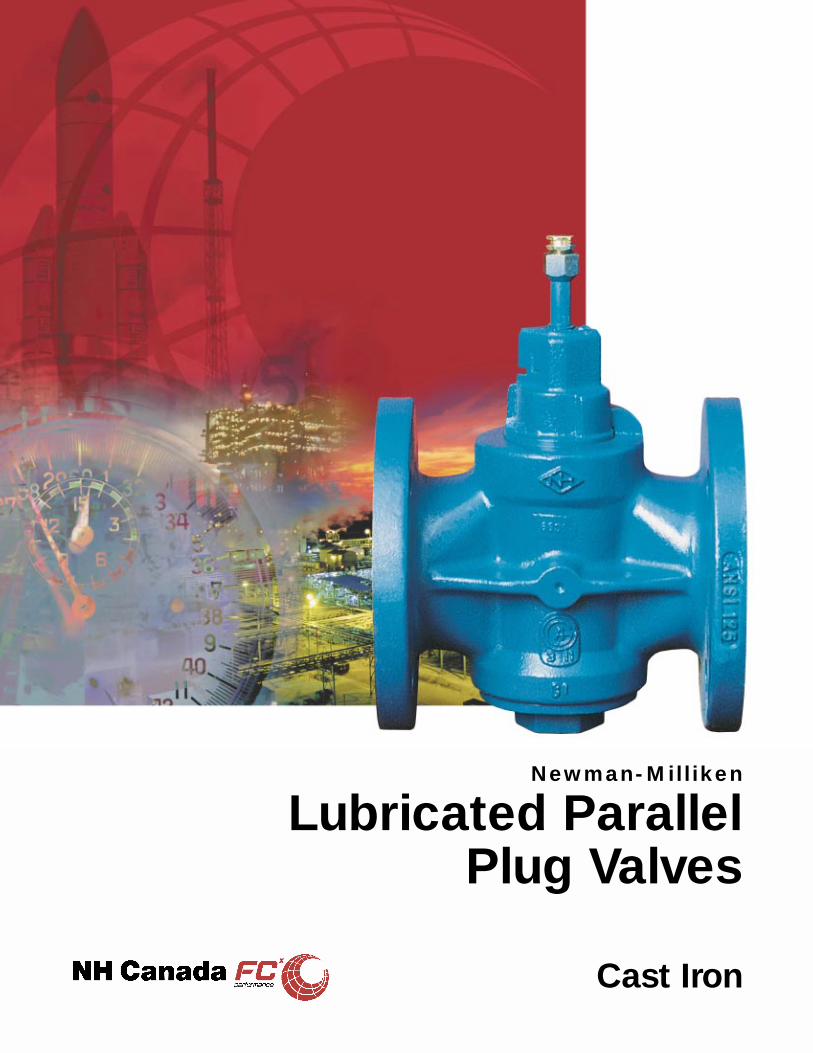
The plug, which is the only moving part in the valve, when ‘open’ presents a straight
through passage inline with the pipe-line, and when turned through 90 degrees to the
‘closed’ position stops the flow.
A special sealing compound is used to effect a completely leak tight seal. When
line pressure is applied to the valve in the closed position, the parallel plug is
forced to the downstream side of the valve. The plug is then in contact with the
body in the area surrounding the outlet port in the body. The sealing compound
which surrounds the outlet port by means of special grooves in the plug, forms a
barrier to line pressure and is also spread over the sealing surfaces of the plug
and body so that a very thin film of compound is established between the plug
and body surfaces on the downstream side.
The metal-to-metal contact of plug and body together with the barrier of
sealing compound ensures a completely leak tight valve.
The sealing compound also preserves the body and
plug surfaces from corrosion and to some
extent, abrasion, and provides
lubrication for ease of operation.
Providing the valve is correctly
maintained, which simply means
injecting a small amount of
sealing compound from time to
time and moving the plug,
positive shut-off will result and
provide many years of
satisfactory service.
The principle of the Newman-Milliken valveis as simple as its design...
GearingGearboxes can be fitted to valves. In the
catalogue, we indicate where we considerthis necessary as standard.Newman-Milliken Plug Valves
170M/171M – 200M/201M are CGA Approved (1/2” – 8”)
CAN/CGA 3.11
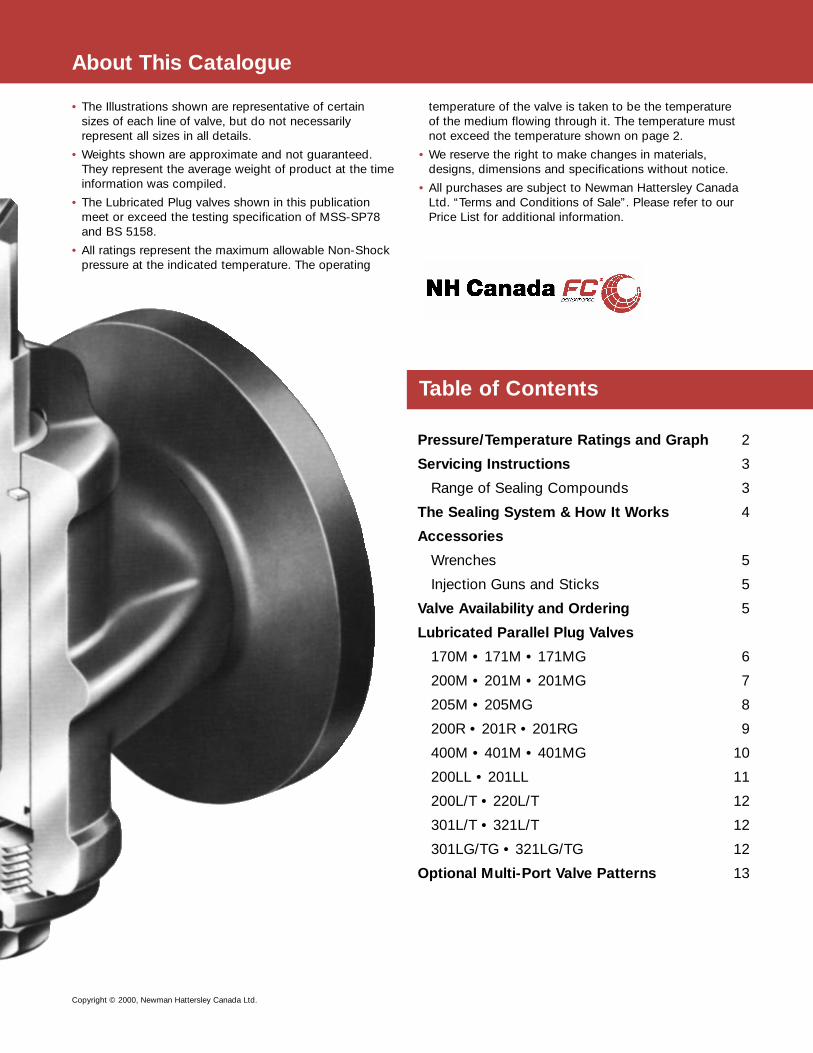
• The Illustrations shown are representative of certainsizes of each line of valve, but do not necessarilyrepresent all sizes in all details.
• Weights shown are approximate and not guaranteed.They represent the average weight of product at the timeinformation was compiled.
• The Lubricated Plug valves shown in this publicationmeet or exceed the testing specification of MSS-SP78and BS 5158.
• All ratings represent the maximum allowable Non-Shockpressure at the indicated temperature. The operating
temperature of the valve is taken to be the temperatureof the medium flowing through it. The temperature mustnot exceed the temperature shown on page 2.
• We reserve the right to make changes in materials,designs, dimensions and specifications without notice.
• All purchases are subject to Newman Hattersley CanadaLtd. “Terms and Conditions of Sale”. Please refer to ourPrice List for additional information.
Pressure/Temperature Ratings and Graph 2
Servicing Instructions 3
Range of Sealing Compounds 3
The Sealing System & How It Works 4
Accessories
Wrenches 5
Injection Guns and Sticks 5
Valve Availability and Ordering 5
Lubricated Parallel Plug Valves
170M • 171M • 171MG 6
200M • 201M • 201MG 7
205M • 205MG 8
200R • 201R • 201RG 9
400M • 401M • 401MG 10
200LL • 201LL 11
200L/T • 220L/T 12
301L/T • 321L/T 12
301LG/TG • 321LG/TG 12
Optional Multi-Port Valve Patterns 13
About This Catalogue
Table of Contents
Copyright © 2000, Newman Hattersley Canada Ltd.

2
Pressure / Temperature Ratings
Valve Specification
Valves fitted withANSI B16.1 Flanges-Class 125
Sizes 1/2” – 12”
Valves fitted withANSI B16.1 Flanges-Class 125
Sizes 14” – 24”
Valves fitted withANSI B16.1 Flanges-Class 250
Sizes 1/2” – 12”
Valves fitted withANSI B16.1 Flanges-Class 250
Sizes 14” – 24”
Screwed End valves- Similar to Class 250
Fig# End Class Nominal PressureConnection Rating Size Body Test Seat Test
lbf / in2 lbf / in2
170M
200M
200R Screwed 125 2” & above 348 200
200L/T
220L/T
200LL Screwed 125 2” & above 350 -
400M Screwed 250 2” & above 750 500
171M
201M
201R Flanged 125 2” – 12” 350 200301L/T 14” & above 265 150
321L/T
205M
201LL Flanged 125 2” & above 350 -
401M Flanged 250 2” – 12” 750 500
Note:The pressure/temperature ratings given apply to the valve only. Themaximum temperature at which a valve may operate dependsupon the sealing compound with which the valve is filled.
However, should the sealing compound have a higher temperaturethan the temperature given in the pressure/temperature ratingsthen the lower temperature must apply.
Hydrostatic Test PressureNote: All valves 1/2” – 1 1/2” inclusive are pneumatically tested to:Body: 300 psiSeat: 100 psi
Pressure/TemperatureRating
125 psi @ 450°F200 psi from -20° – 150°F
100 psi @ 350°F150 psi from -20° – 150°F
250 psi @ 450°F500 psi from -20° – 150°F
200 psi @ 406°F300 psi from -20° – 150°F
253 psi @ 500°F(17.5 bar @ 260°C)
500 psi from -23° – 248°F(34.5 bar from -10° – 120°C)

Servicing InstructionsPositive Isolation with Minimum Maintenance
3
SealingIn service sealing compound should be used for each individual mediumto affect good isolation. Our recommendations for sealing compoundsare the result of considerable research. If there is any doubt as to thesuitability of a particular compound for a given service, tests should becarried out in a new clean valve. This is the only way to conduct suchtests. Laboratory tests using a beaker of line fluid and immersing a stickof compound have proved misleading. Where samples of fluid can besupplied, together with details of temperature and pressure, and if knownfrequency of operation, we will carry out specific tests and give ourrecommendations based upon the results.
ConstructionOnly five major parts are involved when dismantling: i.e. body, parallelplug, PTFE thrust ring, bottom cover and plug support spring.
OperationCare must be taken particularly with geared valves that the plug is easedoff the body stop after operation to ensure the plug is free to float.
Routine MaintenanceValves are dispatched by Hattersley charged with sealing compound. Acompound identification tag states clearly that the valve has beenassembled and tested with a universal compound. The user is advised tofollow the chart overleaf for specific applications. When injectingadditional sealing compound, care should be taken to ensure that it is ofthe correct type. Where the service permits, the valve should be partiallyor fully operated once to ensure free operation and to determine theeffort required.
For infrequently operated valves maintenance merely consists of two orthree turns of the combination screw or, if gun injection, several strokesof the lever, and opening and closing the valve a minimum of three timesto distribute the compound evenly around the plug at three monthlyintervals. It is difficult to specify how often the valve should be rechargedwith sealing compound, since this is determined by the frequency ofoperation, type of service, pressure and temperature.
Injection of CompoundWhen the combination screw has reached its limit (screwed fully down),this indicates that the valve needs re-charging with sealing compound.
When using sticks or the lightweight compound gun, remove thecombination screw, insert a stick or partially fill the compound reservoir inthe plug, replace the combination screw, and screw down.
This operation may need repeating several times. When using the NMG40 high-pressure gun, attach the nozzle to the injection nipple and giveseveral steady strokes of the lever.
VALVES MUST EITHER BE FULLY OPEN OR FULLY CLOSED WHILETHEY ARE BEING CHARGED.
Indication of Full ChargingThe first indication of the valve becoming fully charged is an increase inthe effort required to rotate the combination screw, or with the highpressure gun injection an increase in the effort required on the lever.
The effort required to operate the valve should have increased from theinitial operation prior to injection of sealing compound.
Method of InjectionWhere the number of valves to be charged is small, i.e. 12 – 15 valves,especially if they are in the smaller sizes, stick or lightweight gun injectioncan be successfully used. For larger quantities use of the NMG 40 highpressure gun is recommended.
Valve LeakageLeakage through the valve indicates that the valve requires injection ofsealing compound or that it needs opening and closing a minimum ofthree times to distribute the compound evenly.
Operating TorqueShould a valve become jammed or unusually stiff to operate, this cangenerally be cured by the injection of sealing compound. If this isineffective, it will be necessary to dismantle the valve, clean thecomponents and recharge with sealing compound.
ServicingAdvice is available from the Hattersley Service Department in connectionwith all aspects of operation, lubrication and maintenance.
Sticks Sealing CompoundSize (in. dia.) 3⁄8 1⁄2 5⁄8Size (mm dia.) 9.50 13 16
Reference A B C
Sticks per box 30 30 30
Number of sticks required to refill sealing compound grooves onlyValve size (in.) 1⁄2 3⁄4 1 11⁄4 11⁄2 2 21⁄2 3 4 5 6 8 10Rectangular Port valve 1 2 2 2 2 2 2 2 2 2 3 2 3
Round Port valve 1 2 2 2 2 1 3 2 3 3 4 5 6
Three-way valve 2 2 2 2 2 2 2 2 2 3 4 3 -
Range of Sealing CompoundsNo. Temperature Colour of Colour of Availability DO NOT Cleaning
Range Compound Box label use for Solvent
17 0° to 300°F Light Brown Salmon Tubes, Bulk and Strong Trichloroethane-18° to 150°C prepacked cartridges Chemicals
18* 32° to 450°F Black Buff Stick and Bulk Water/Strong Water,0° to 230°C Chemicals Trichloroethane
35 -4° to 400°F White Orange Stick, Bulk and Mineral Oils, Paraffin,-20° to 205°C prepacked cartridges Solvents White Spirit
36* 5° to 175°F Black Red Stick and Bulk Mineral Oils, Paraffin,-15° to 80°C Solvents White Spirit
44 -40° to 284°F Black Green Tubes, Bulk and Strong Trichloroethane-40° to 140°C prepacked cartridges Chemicals
74 -31° to 500°F Grey Apple Green Stick, Bulk and Nitrating Acids Paraffin,-34° to 260°C prepacked cartridges Steam, HTHW Hot Water
90** -20° to 375°F White White Bulk and prepacked Solvents Acetone-30° to 190°C cartridges
*Not suitable for gun injection**UK WFBS Listed
4
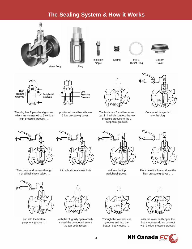
The Sealing System & How it Works
The plug has 2 peripheral grooves,which are connected to 2 vertical
high pressure grooves . . .
positioned on either side are2 low pressure grooves.
The body has 2 small recessescast in it which connect the low
pressure grooves to the 2peripheral grooves.
Compound is injectedinto the plug.
The compound passes througha small ball check valve . . .
into a horizontal cross hole and into the topperipheral groove.
From here it is forced down thehigh pressure grooves . . .
and into the bottomperipheral groove . . .
with the plug fully open or fullyclosed the compound enters
the top body recess.
Through the low pressuregrooves and into the
bottom body recess . . .
with the valve partly open thebody recesses do no connectwith the low pressure grooves.
Plug
Injectionnipple
Valve Body
Spring PTFEThrust Ring
BottomCover
LowPressureGrooves
PeripheralGrooves
HighPressureGrooves
Valve Availability & Ordering
OrderingPlease be sure to quote the correct catalogue numbers when orderingNewman-Milliken valves. It is also important to state the exact detailsof the service (pressure, temperature, nature of liquid, gas, etc.) toensure that the correct sealing compound is supplied. In the case ofacids, state concentration. The following abbreviations are used whenreferring to the Newman-Milliken valves in the pages of this catalogue.
G - Gear-Operated
R - Round Port
SJ - Steam Jacketed Bottom Cover
Fig # ANSI B16.1 ScrewedClass 125 Class 250 Class 250
170M171M + 171MG •200M201M + 201MG •200R201R + 201RG •205M + 205MG •200L + 200T321L + 321LG •301T + 301TG •220L + 221T321L + 321LG •321T + 321TG •400M •401M + 401MG •200LL •201LL •
Material SpecificationsComponent Material Specification
ASTM
Plug Cast Iron A126 CIB
Body Cast Iron A126 CIB
Thrust Washer PTFE
Bottom Cover Cast Iron A126 CIBSG Iron
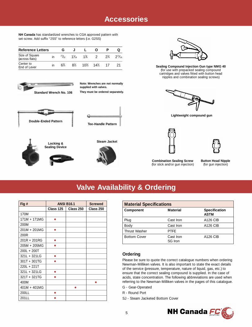
Reference Letters G J L O P QSize of Square in 27⁄32 11⁄16 13⁄8 2 21⁄4 211⁄16(across flats)Center to in 63⁄4 81⁄2 101⁄2 141⁄2 17 21End of Lever
NH Canada has standardized wrenches to CGA approved pattern withset-screw. Add suffix “2SS” to reference letters (i.e. G2SS)
Note: Wrenches are not normallysupplied with valves.
They must be ordered separately.
Lightweight compound gun
Button Head Nipple(for gun injection)
Combination Sealing Screw(for stick and/or gun injection)
Sealing Compound Injection Gun type NMG 40(for use with prepacked sealing compound
cartridges and valves fitted with button headnipples and combination sealing screws)
Double-Ended PatternTee-Handle Pattern
Steam JacketLocking &Sealing Device
Standard Wrench No. 106
Accessories
5
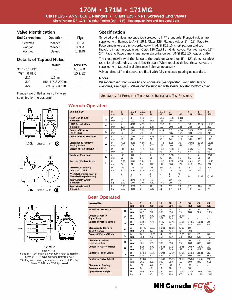
Nominal Size in 1 1 1/4 1 1/2 2 2 1/2 3 4 5 6 8mm 25 32 40 50 65 80 100 125 150 200
170M End-to-End in 3.63 4 4.38 6 6.50 7.38 8.88 - - -(Screwed) A mm 92 102 111 152 165 187 225 - - -
171M Face-to-Face in 4 4.38 4.63 7 7.50 8 9 10 10.50 11.50(Flanged) B mm 102 111 118 178 190 203 225 254 267 292
Center of Port to in 2.50 2.63 3.13 3.56 4.94 5.31 6.56 7.25 8.38 9.50Top of Plug E mm 64 67 79 90 125 135 167 184 213 241
Center of Port to Bottom in 1.56 1.94 2.25 2.69 3.25 3.69 4.38 5.56 6.56 7.75F mm 40 49 57 68 83 94 111 141 167 197
Clearance to Remove in 4.06 4.25 4.69 5 7.75 8.38 10 10.63 11.75 12.88Sealing Screw G mm 103 108 119 127 197 206 254 270 298 327
Square of Plug Head A/F in .84 .84 1.06 1.06 1.38 1.38 2 2.25 2.25 2.69J mm 21 21 27 27 35 35 51 57 57 63
Height of Plug Head in .88 .88 1 1 1.38 1.38 2 2 2 2.50K mm 22 22 25 25 35 35 51 51 51 64
Greatest Width of Body in 2.50 2.50 2.88 4 4.50 5.25 6.75 8.63 10 11.50L mm 64 64 73 102 114 133 171 219 254 292
Diameter of Sealing in .38 .38 .38 .38 .50 .50 .63 .63 .63 .63Compound Stick mm 9.50 9.50 9.50 9.50 13 13 16 16 16 16
Wrench (Screwed valves) G G J J L L O - - -Wrench (Flanged valves) G G J J L L O P P106 Q106
Approximate Weight lb 3.70 4.20 5.30 9.50 15 22 46 - - -(Screwed) kg 1.70 1.90 2.40 4.30 6.60 10 21 - - -
Approximate Weight lb 6.40 9.20 11 18 24 37 53 97 126 170(Flanged) kg 2.90 4.20 5 8.20 11 17 24 44 57 77
Nominal Size in 6 8 10 12 16 18 20 24mm 150 200 250 300 400 450 500 600
171MG Face-to-Face in 10.50 11.50 13 14 30 34 36 42B mm 267 292 330 356 762 864 914 1067
Center of Port to in 8.38 9.50 11.94 13.69 15.94 - - -Top of Plug E mm 213 241 303 348 405 - - -
Center of Port to Bottom in 6.56 7.75 9.75 11.48 13.56 17.56 19.81 22F mm 167 197 248 291 344 446 503 559
Clearance to Remove in 11.75 12.88 16.63 18.63 20.63 30 - -Sealing Screw G mm 298 327 422 473 524 762 - -
Greatest Width of Body in 10 11.50 14 17 20.50 22 27 30L mm 254 292 356 432 521 559 686 762
Diameter of Wheel, in 15 21 21 21 30 26 26 26outside spokes Q mm 381 533 533 533 762 660 660 660
Center to Face of Wheel in 8.25 9.50 13.38 13.38 16.48 16.50 16.50 21R mm 210 241 340 340 418 419 419 533
Center to Top of Wheel in 14.94 18.63 20.94 22.69 29.06 31.63 33.31 36S mm 379 473 532 576 738 802 843 914
Center to End of Wheel in 11.06 15 15.69 15.69 21.19 15.69 15.69 20.13T mm 281 381 398 398 538 399 399 511
Diameter of Sealing in .63 .63 .63 .63 .63 .63 - -Compound Stick mm 16 16 16 16 16 16 - -
Approximate Weight lb 156 209 359 493 1228 1375 2618 3542kg 71 95 163 224 558 625 1190 1610
Gear Operated
Wrench Operated
6
170M • 171M • 171MGClass 125 - ANSI B16.1 Flanges • Class 125 - NPT Screwed End Valves
Short Pattern (2”– 12”) Regular Pattern (16” – 24”) Rectangular Port and Reduced Bore
171MG*Sizes 6” – 24”
Sizes 18” – 24” supplied with fully enclosed gearingSizes 6” – 12” have screwed bottom cover
*Sealing compound gun required on sizes 20” – 24”Sizes 6” & 8” are CGA Approved
170M Sizes 1” – 4”
171M Sizes 1” – 8”
SpecificationScrewed end valves are supplied screwed to NPT standards. Flanged valves aresupplied with flanges to ANSI 16.1, Class 125. Flanged valves 2” – 12”, Face-to-Face dimensions are in accordance with ANSI B16.10, short pattern and aretherefore interchangeable with Class 125 Cast Iron Gate valves. Flanged valves 16” –24”, Face-to-Face dimensions are in accordance with ANSI B16.10, regular pattern.
The close proximity of the flange to the body on valve sizes 5” – 12”, does not allowroom for all bolt holes to be drilled through. When required drilled, these valves aresupplied with tapped and clearance holes as necessary.
Valves, sizes 18” and above, are fitted with fully enclosed gearing as standard.
Details of Tapped HolesMetric ANSI 125
3/4” – 10 UNC - 5, 6 & 8”7/8” – 9 UNC - 10 & 12”
M16 125 mm -M20 150, 175 & 200 mm -M24 250 & 300 mm -
Notes:We recommend that valves 6” and above are gear operated. For particulars ofwrenches, see page 5. Valves can be supplied with steam jacketed bottom cover.
Valve IdentificationEnd Connections Operation Fig#
Screwed Wrench 170MFlanged Wrench 171MFlanged Geared 171MG
See page 2 for Pressure / Temperature Ratings and Test PressuresFlanges are drilled unless otherwisespecified by the customer.
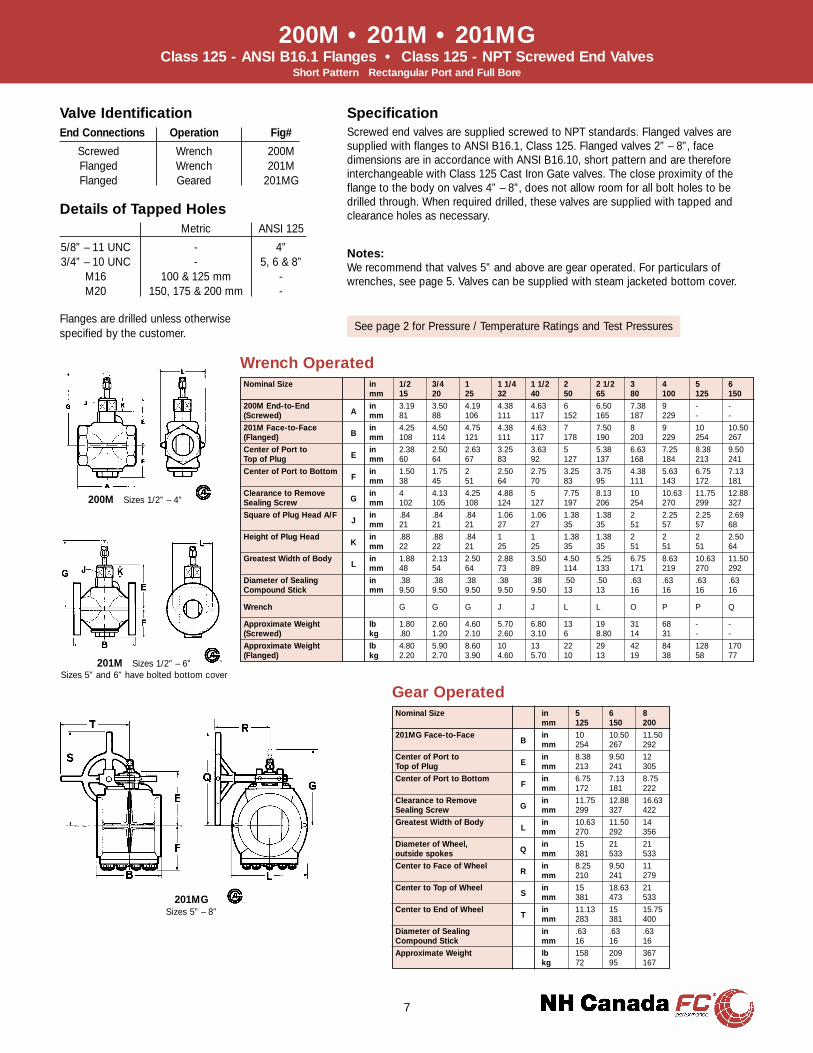
200M • 201M • 201MGClass 125 - ANSI B16.1 Flanges • Class 125 - NPT Screwed End Valves
Short Pattern Rectangular Port and Full Bore
Nominal Size in 1/2 3/4 1 1 1/4 1 1/2 2 2 1/2 3 4 5 6mm 15 20 25 32 40 50 65 80 100 125 150
200M End-to-End in 3.19 3.50 4.19 4.38 4.63 6 6.50 7.38 9 - -(Screwed) A mm 81 88 106 111 117 152 165 187 229 - -
201M Face-to-Face in 4.25 4.50 4.75 4.38 4.63 7 7.50 8 9 10 10.50(Flanged) B mm 108 114 121 111 117 178 190 203 229 254 267
Center of Port to in 2.38 2.50 2.63 3.25 3.63 5 5.38 6.63 7.25 8.38 9.50Top of Plug E mm 60 64 67 83 92 127 137 168 184 213 241
Center of Port to Bottom in 1.50 1.75 2 2.50 2.75 3.25 3.75 4.38 5.63 6.75 7.13F mm 38 45 51 64 70 83 95 111 143 172 181
Clearance to Remove in 4 4.13 4.25 4.88 5 7.75 8.13 10 10.63 11.75 12.88Sealing Screw G mm 102 105 108 124 127 197 206 254 270 299 327
Square of Plug Head A/F in .84 .84 .84 1.06 1.06 1.38 1.38 2 2.25 2.25 2.69J mm 21 21 21 27 27 35 35 51 57 57 68
Height of Plug Head in .88 .88 .84 1 1 1.38 1.38 2 2 2 2.50K mm 22 22 21 25 25 35 35 51 51 51 64
Greatest Width of Body in 1.88 2.13 2.50 2.88 3.50 4.50 5.25 6.75 8.63 10.63 11.50L mm 48 54 64 73 89 114 133 171 219 270 292
Diameter of Sealing in .38 .38 .38 .38 .38 .50 .50 .63 .63 .63 .63Compound Stick mm 9.50 9.50 9.50 9.50 9.50 13 13 16 16 16 16
Wrench G G G J J L L O P P Q
Approximate Weight lb 1.80 2.60 4.60 5.70 6.80 13 19 31 68 - -(Screwed) kg .80 1.20 2.10 2.60 3.10 6 8.80 14 31 - -
Approximate Weight lb 4.80 5.90 8.60 10 13 22 29 42 84 128 170(Flanged) kg 2.20 2.70 3.90 4.60 5.70 10 13 19 38 58 77
Nominal Size in 5 6 8mm 125 150 200
201MG Face-to-Face in 10 10.50 11.50B mm 254 267 292
Center of Port to in 8.38 9.50 12Top of Plug E mm 213 241 305
Center of Port to Bottom in 6.75 7.13 8.75F mm 172 181 222
Clearance to Remove in 11.75 12.88 16.63Sealing Screw G mm 299 327 422
Greatest Width of Body in 10.63 11.50 14L mm 270 292 356
Diameter of Wheel, in 15 21 21outside spokes Q mm 381 533 533
Center to Face of Wheel in 8.25 9.50 11R mm 210 241 279
Center to Top of Wheel in 15 18.63 21S mm 381 473 533
Center to End of Wheel in 11.13 15 15.75T mm 283 381 400
Diameter of Sealing in .63 .63 .63Compound Stick mm 16 16 16
Approximate Weight lb 158 209 367kg 72 95 167
Gear Operated
Wrench Operated
201MGSizes 5” – 8”
200M Sizes 1/2” – 4”
201M Sizes 1/2” – 6”Sizes 5” and 6” have bolted bottom cover
7
Valve IdentificationEnd Connections Operation Fig#
Screwed Wrench 200MFlanged Wrench 201MFlanged Geared 201MG
Notes:We recommend that valves 5” and above are gear operated. For particulars ofwrenches, see page 5. Valves can be supplied with steam jacketed bottom cover.
SpecificationScrewed end valves are supplied screwed to NPT standards. Flanged valves aresupplied with flanges to ANSI B16.1, Class 125. Flanged valves 2” – 8”, facedimensions are in accordance with ANSI B16.10, short pattern and are thereforeinterchangeable with Class 125 Cast Iron Gate valves. The close proximity of theflange to the body on valves 4” – 8”, does not allow room for all bolt holes to bedrilled through. When required drilled, these valves are supplied with tapped andclearance holes as necessary.Details of Tapped Holes
Metric ANSI 125
5/8” – 11 UNC - 4”3/4” – 10 UNC - 5, 6 & 8”
M16 100 & 125 mm -M20 150, 175 & 200 mm -
Flanges are drilled unless otherwisespecified by the customer.
See page 2 for Pressure / Temperature Ratings and Test Pressures

205M • 205MGClass 125 - ANSI B16.1 Flanges
Regular Pattern Rectangular Port Full Bore (1” – 12”) Reduced Bore (14” – 24”)
Nominal Size in 1 1 1/2 2 2 1/2 3 4 5 6mm 25 40 50 65 80 100 125 150
205M Face-to-Face in 5.50 6.50 8 8.75 9.50 12 14 15.50(Flanged) B mm 140 165 203 222 241 305 356 394
Center of Port to Top in 2.63 3.63 5 5.38 6.63 7.25 8.38 9.50of Plug E mm 67 92 127 137 168 184 213 241
Center of Port to in 2 2.75 3.25 3.75 4.38 5.63 6.75 7.13Bottom F mm 51 70 83 95 111 143 172 181
Clearance to Remove in 4.25 5 7.75 8.13 10 10.63 11.75 12.88Sealing Screw G mm 108 127 197 206 254 270 299 327
Square of Plug Head A/F in .84 1.06 1.38 1.38 2 2.25 2.25 2.69J mm 21 27 35 35 51 57 57 68
Height of Plug Head in .84 1 1.38 1.38 2 2 2 2.50K mm 21 25 35 35 51 51 51 64
Greatest Width of Body in 2.50 3.50 4.50 5.25 6.75 8.63 10.63 11.50L mm 64 89 114 133 172 219 270 292
Diameter of Sealing in .38 .38 .50 .50 .63 .63 .63 .63Compound Stick mm 9.50 9.50 13 13 16 16 16 16
Wrench G J L L O P P Q
Approximate Weight lb 9 14 22 31 44 84 137 181(Flanged) kg 4.10 6.20 10 14 20 38 62 82
Gear Operated
Wrench Operated
Nominal Size in 5 6 8 10 12 14 16 18 20 24mm 125 150 200 250 300 350 400 450 500 600
205MG Face-to-Face in 14 15.50 18 21 24 27 30 34 36 42B mm 356 394 457 533 610 686 762 864 914 1067
Center of Port to Top of in 8.38 9.50 12 13.75 16 16 - - - -Plug E mm 213 241 305 349 406 406 - - - -
Center of Port to Bottom in 6.75 7.13 8.75 11.13 13.63 13.63 17.63 19.88 22 25.38F mm 172 181 222 283 346 346 448 505 559 645
Clearance to Remove in 11.75 12.88 16.63 18.88 20.63 20.63 30 - - -Sealing Screw G mm 299 327 422 473 524 524 762 - - -
Greatest Width of Body in 10.63 11.50 14 16.25 20.50 20.50 22 27 30.75 33L mm 270 292 356 413 521 521 559 686 781 838
Diameter of Wheel, in 15 21 21 21 30 30 26 26 26 26outside spokes Q mm 381 533 533 533 762 762 660 660 660 660
Center to Face of Wheel in 8.25 9.50 11 13.38 15.38 15.38 16.50 16.50 21 21.63R mm 210 241 279 340 391 391 419 419 533 556
Center to Top of Wheel in 15 18.63 21 22.75 29.13 29.13 31.63 33.25 36 39S mm 381 473 533 578 740 740 802 845 914 991
Center to End of Wheel in 11.13 15 15.75 15.75 21.38 21.38 15.75 15.75 20.13 22.38T mm 283 381 400 400 543 543 400 400 511 568
Diameter of Sealing in .63 .63 .63 .63 .63 .63 .63 - - -Compound Stick mm 16 16 16 16 16 16 16 - - -
Approximate Weight lb 168 220 374 572 845 1025 1540 2387 3245 4675kg 76 100 170 260 384 466 700 1085 1475 2125
8
205M Sizes 1” – 6”Sizes 5” and 6” have bolted bottom cover
205MG Sizes 5” – 24”Sizes 16” – 24” are fitted with fully enclosed gearing*Sealing compound gun required on sizes 18” – 24”
SpecificationFlanged valves are supplied with flanges to ANSI B16.1, Class 125, regular pattern.
Notes:We recommend that valves 5” and above are gear operated. For particulars ofwrenches, see page 5. Valves can be supplied with steam jacketed bottom cover.
Valve IdentificationEnd Connections Operation Fig#
Flanged Wrench 205MFlanged Geared 205MG
Flanges are drilled unless otherwisespecified by the customer.
See page 2 for Pressure / Temperature Ratings and Test Pressures
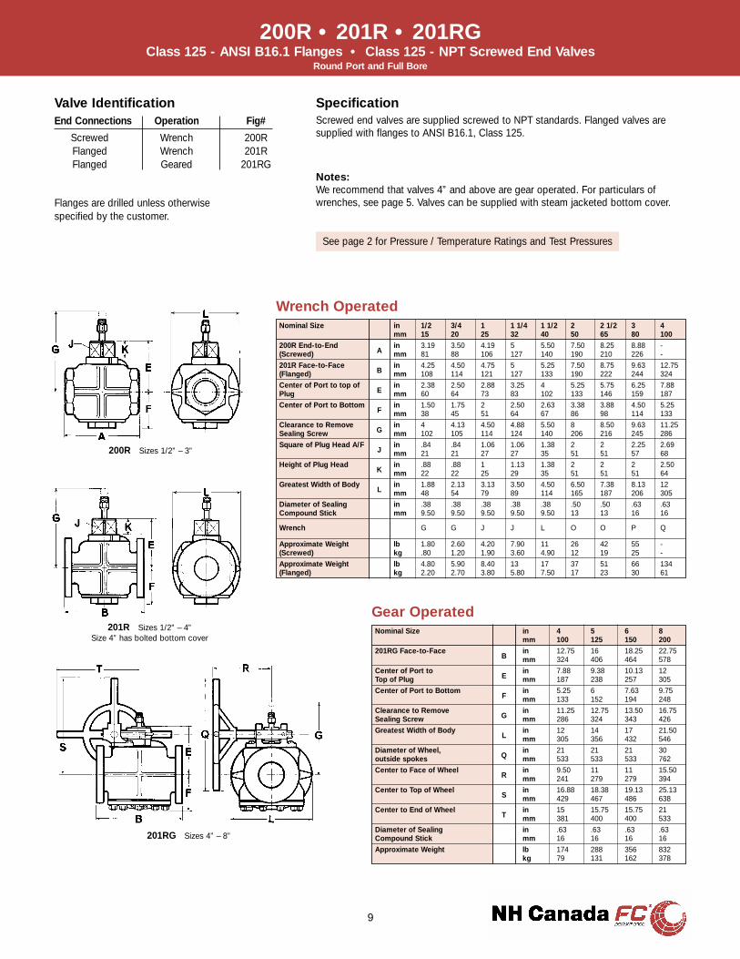
Valve IdentificationEnd Connections Operation Fig#
Screwed Wrench 200RFlanged Wrench 201RFlanged Geared 201RG
200R • 201R • 201RGClass 125 - ANSI B16.1 Flanges • Class 125 - NPT Screwed End Valves
Round Port and Full Bore
Nominal Size in 1/2 3/4 1 1 1/4 1 1/2 2 2 1/2 3 4mm 15 20 25 32 40 50 65 80 100
200R End-to-End in 3.19 3.50 4.19 5 5.50 7.50 8.25 8.88 -(Screwed) A mm 81 88 106 127 140 190 210 226 -
201R Face-to-Face in 4.25 4.50 4.75 5 5.25 7.50 8.75 9.63 12.75(Flanged) B mm 108 114 121 127 133 190 222 244 324
Center of Port to top of in 2.38 2.50 2.88 3.25 4 5.25 5.75 6.25 7.88Plug E mm 60 64 73 83 102 133 146 159 187
Center of Port to Bottom in 1.50 1.75 2 2.50 2.63 3.38 3.88 4.50 5.25F mm 38 45 51 64 67 86 98 114 133
Clearance to Remove in 4 4.13 4.50 4.88 5.50 8 8.50 9.63 11.25Sealing Screw G mm 102 105 114 124 140 206 216 245 286
Square of Plug Head A/F in .84 .84 1.06 1.06 1.38 2 2 2.25 2.69J mm 21 21 27 27 35 51 51 57 68
Height of Plug Head in .88 .88 1 1.13 1.38 2 2 2 2.50K mm 22 22 25 29 35 51 51 51 64
Greatest Width of Body in 1.88 2.13 3.13 3.50 4.50 6.50 7.38 8.13 12L mm 48 54 79 89 114 165 187 206 305
Diameter of Sealing in .38 .38 .38 .38 .38 .50 .50 .63 .63Compound Stick mm 9.50 9.50 9.50 9.50 9.50 13 13 16 16
Wrench G G J J L O O P Q
Approximate Weight lb 1.80 2.60 4.20 7.90 11 26 42 55 -(Screwed) kg .80 1.20 1.90 3.60 4.90 12 19 25 -
Approximate Weight lb 4.80 5.90 8.40 13 17 37 51 66 134(Flanged) kg 2.20 2.70 3.80 5.80 7.50 17 23 30 61
Nominal Size in 4 5 6 8mm 100 125 150 200
201RG Face-to-Face in 12.75 16 18.25 22.75B mm 324 406 464 578
Center of Port to in 7.88 9.38 10.13 12Top of Plug E mm 187 238 257 305
Center of Port to Bottom in 5.25 6 7.63 9.75F mm 133 152 194 248
Clearance to Remove in 11.25 12.75 13.50 16.75Sealing Screw G mm 286 324 343 426
Greatest Width of Body in 12 14 17 21.50L mm 305 356 432 546
Diameter of Wheel, in 21 21 21 30outside spokes Q mm 533 533 533 762
Center to Face of Wheel in 9.50 11 11 15.50R mm 241 279 279 394
Center to Top of Wheel in 16.88 18.38 19.13 25.13S mm 429 467 486 638
Center to End of Wheel in 15 15.75 15.75 21T mm 381 400 400 533
Diameter of Sealing in .63 .63 .63 .63Compound Stick mm 16 16 16 16
Approximate Weight lb 174 288 356 832kg 79 131 162 378
Gear Operated
Wrench Operated
201RG Sizes 4” – 8”
200R Sizes 1/2” – 3”
201R Sizes 1/2” – 4”Size 4” has bolted bottom cover
9
Notes:We recommend that valves 4” and above are gear operated. For particulars ofwrenches, see page 5. Valves can be supplied with steam jacketed bottom cover.
SpecificationScrewed end valves are supplied screwed to NPT standards. Flanged valves aresupplied with flanges to ANSI B16.1, Class 125.
Flanges are drilled unless otherwisespecified by the customer.
See page 2 for Pressure / Temperature Ratings and Test Pressures

Nominal Size in 1/2 3/4 1 1 1/4 1 1/2 2 2 1/2 3 4mm 15 20 25 32 40 50 65 80 100
400M End-to-End in 3.19 3.50 4.19 4.38 4.63 6 6.50 7.38 9(Screwed) A mm 81 88 106 111 117 152 165 187 229
401M Face-to-Face in 4.50 4.75 5.25 4.88 5.13 8.50 9.50 11.13 12(Flanged) B mm 114 121 133 124 130 216 241 283 305
Center of Port to Top of in 2.38 2.50 2.63 3.25 3.63 5 5.38 6.63 7.25Plug E mm 60 64 67 83 92 127 137 168 184
Center of Port to Bottom in 1.50 1.75 2 2.38 2.75 3.25 3.75 4.38 5.63F mm 38 45 51 60 70 83 95 111 143
Clearance to Remove in 4 4.13 4.25 4.88 5 7.38 8.13 10 10.63Sealing Screw G mm 102 105 108 124 127 187 206 254 270
Square of Plug Head A/F in .84 .84 .84 1.06 1.06 1.38 1.38 2 2.25J mm 21 21 21 27 27 35 35 51 57
Height of Plug Head in .88 .88 .88 1 1 1.38 1.38 2 2K mm 22 22 22 25 25 35 35 51 51
Greatest Width of Body in 1.88 2.13 2.50 2.88 3.50 4.50 5.25 6.75 8.63L mm 48 54 64 73 89 114 133 172 219
Diameter of Sealing in .38 .38 .38 .38 .38 .50 .50 .63 .63Compound Stick mm 9.50 9.50 9.50 9.50 9.50 13 13 16 16
Wrench G G G J J L L O P
Approximate Weight lb 2 2.90 4.60 5.30 6.60 14 18 31 73(Screwed) kg .90 1.30 2.10 2.40 3 6.20 8.20 14 33
Approximate Weight lb 6.60 7.70 11 12 15 33 37 62 112(Flanged) kg 3 3.50 5 5.60 7 15 17 28 51
Nominal Size in 5 6 8 10 12mm 125 150 200 250 300
401MG Face-to-Face in 15 15.88 16.50 22.50 25B mm 381 403 419 572 635
Center of Port to in 8.38 9.50 12 13.75 16Top of Plug E mm 213 241 305 349 406
Center of Port to Bottom in 6.75 7.13 8.75 11.13 13.63F mm 172 181 222 283 346
Clearance to Remove in 11.75 12.88 16.63 18.38 20.63Sealing Screw G mm 299 327 422 467 524
Greatest Width of Body in 10.63 11.50 15.50 16.25 20.50L mm 270 292 394 413 521
Diameter of Wheel, in 15 21 21 21 30outside spokes Q mm 381 533 533 533 762
Center to Face of Wheel in 8.25 9.50 11 13.38 15.50R mm 210 241 279 340 394
Center to Top of Wheel in 15 18.63 21 22.75 29.13S mm 381 473 533 579 740
Center to End of Wheel in 11.13 15 15.75 15.75 21.38T mm 283 381 400 400 543
Diameter of Sealing in .63 .63 .63 .63 .63Compound Stick mm 16 16 16 16 16
Approximate Weight lb 202 264 381 647 953kg 92 120 173 294 433
Gear Operated
Wrench Operated
10
400M • 401M • 401MGClass 250 - ANSI B16.1 Flanges • Class 250 - NPT Screwed End Valves
Regular Pattern Round Port (1/2” & 3/4”) Rectangular Port (1” – 12”) and Full Bore
401MG Sizes 5” – 12”
400M Sizes 1/2” – 4”
401M Sizes 1/2” – 4”
Valve IdentificationEnd Connections Operation Fig#
Screwed Wrench 400MFlanged Wrench 401MFlanged Geared 401MG
SpecificationScrewed end valves are supplied screwed to NPT standards. Flanged valves aresupplied with flanges to ANSI B16.1, Class 250. Flanged valves 2” – 8” Face-to-Face dimensions are in accordance with ANSI B16.10, Class 250 Gate valves. Valves2” – 4” are in accordance with ANSI B16.10, Class 250, regular pattern.
Notes:We recommend that valves 5” and above are gear operated. For particulars ofwrenches, see page 5. Valves can be supplied with steam jacketed bottom cover.
Flanges are drilled unless otherwisespecified by the customer. See page 2 for Pressure / Temperature Ratings and Test Pressures
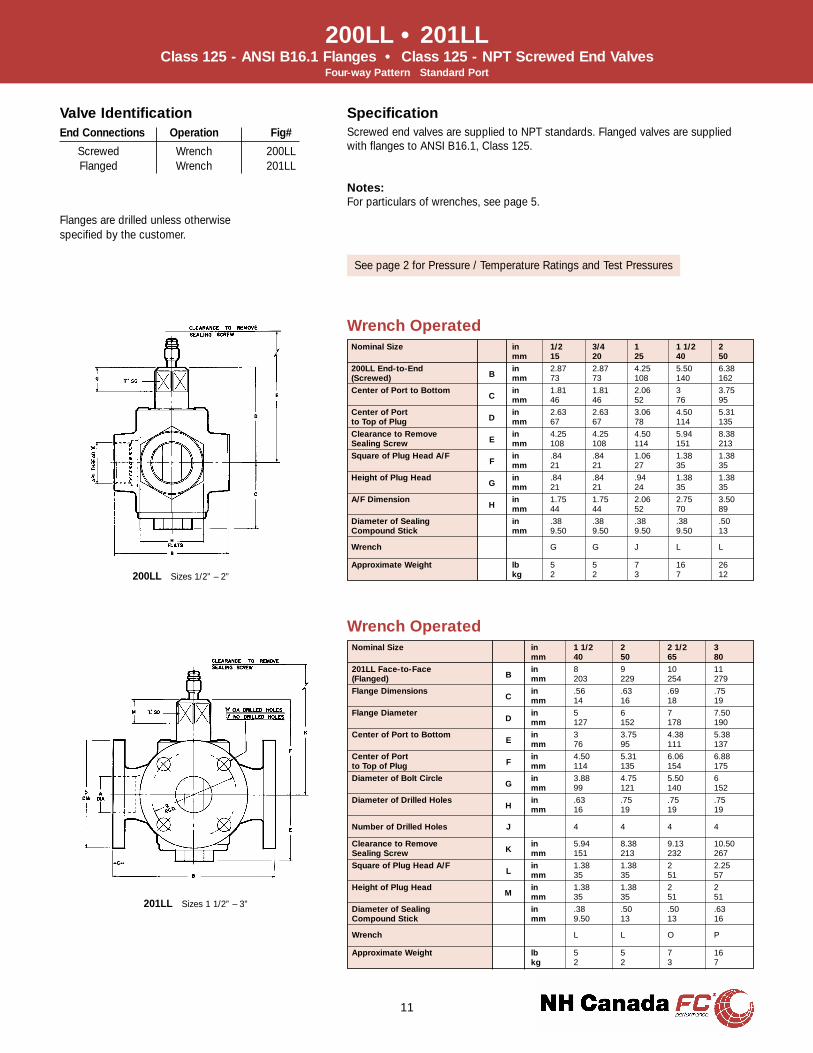
200LL • 201LLClass 125 - ANSI B16.1 Flanges • Class 125 - NPT Screwed End Valves
Four-way Pattern Standard Port
Nominal Size in 1/2 3/4 1 1 1/2 2mm 15 20 25 40 50
200LL End-to-End in 2.87 2.87 4.25 5.50 6.38(Screwed) B mm 73 73 108 140 162
Center of Port to Bottom in 1.81 1.81 2.06 3 3.75C mm 46 46 52 76 95
Center of Port in 2.63 2.63 3.06 4.50 5.31to Top of Plug D mm 67 67 78 114 135
Clearance to Remove in 4.25 4.25 4.50 5.94 8.38Sealing Screw E mm 108 108 114 151 213
Square of Plug Head A/F in .84 .84 1.06 1.38 1.38F mm 21 21 27 35 35
Height of Plug Head in .84 .84 .94 1.38 1.38G mm 21 21 24 35 35
A/F Dimension in 1.75 1.75 2.06 2.75 3.50H mm 44 44 52 70 89
Diameter of Sealing in .38 .38 .38 .38 .50Compound Stick mm 9.50 9.50 9.50 9.50 13
Wrench G G J L L
Approximate Weight lb 5 5 7 16 26kg 2 2 3 7 12
Wrench Operated
Nominal Size in 1 1/2 2 2 1/2 3mm 40 50 65 80
201LL Face-to-Face in 8 9 10 11(Flanged) B mm 203 229 254 279
Flange Dimensions in .56 .63 .69 .75C mm 14 16 18 19
Flange Diameter in 5 6 7 7.50D mm 127 152 178 190
Center of Port to Bottom in 3 3.75 4.38 5.38E mm 76 95 111 137
Center of Port in 4.50 5.31 6.06 6.88to Top of Plug F mm 114 135 154 175
Diameter of Bolt Circle in 3.88 4.75 5.50 6G mm 99 121 140 152
Diameter of Drilled Holes in .63 .75 .75 .75H mm 16 19 19 19
Number of Drilled Holes J 4 4 4 4
Clearance to Remove in 5.94 8.38 9.13 10.50Sealing Screw K mm 151 213 232 267
Square of Plug Head A/F in 1.38 1.38 2 2.25L mm 35 35 51 57
Height of Plug Head in 1.38 1.38 2 2M mm 35 35 51 51
Diameter of Sealing in .38 .50 .50 .63Compound Stick mm 9.50 13 13 16
Wrench L L O P
Approximate Weight lb 5 5 7 16kg 2 2 3 7
Wrench Operated
11
201LL Sizes 1 1/2” – 3”
200LL Sizes 1/2” – 2”
SpecificationScrewed end valves are supplied to NPT standards. Flanged valves are suppliedwith flanges to ANSI B16.1, Class 125.
Notes:For particulars of wrenches, see page 5.
Valve IdentificationEnd Connections Operation Fig#
Screwed Wrench 200LLFlanged Wrench 201LL
Flanges are drilled unless otherwisespecified by the customer.
See page 2 for Pressure / Temperature Ratings and Test Pressures
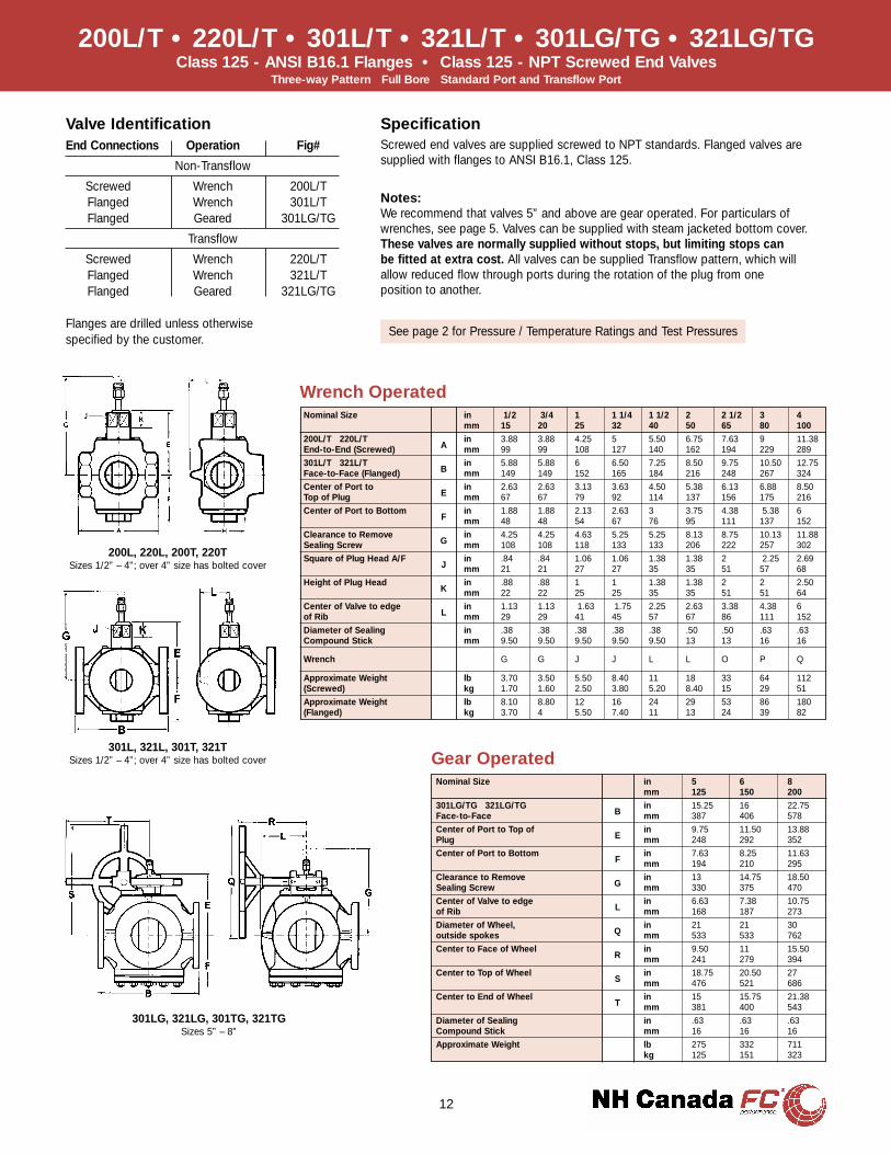
Valve IdentificationEnd Connections Operation Fig#
Non-Transflow
Screwed Wrench 200L/TFlanged Wrench 301L/TFlanged Geared 301LG/TG
Transflow
Screwed Wrench 220L/TFlanged Wrench 321L/TFlanged Geared 321LG/TG
12
200L/T • 220L/T • 301L/T • 321L/T • 301LG/TG • 321LG/TGClass 125 - ANSI B16.1 Flanges • Class 125 - NPT Screwed End Valves
Three-way Pattern Full Bore Standard Port and Transflow Port
Nominal Size in 1/2 3/4 1 1 1/4 1 1/2 2 2 1/2 3 4mm 15 20 25 32 40 50 65 80 100
200L/T 220L/T in 3.88 3.88 4.25 5 5.50 6.75 7.63 9 11.38End-to-End (Screwed) A mm 99 99 108 127 140 162 194 229 289
301L/T 321L/T in 5.88 5.88 6 6.50 7.25 8.50 9.75 10.50 12.75Face-to-Face (Flanged) B mm 149 149 152 165 184 216 248 267 324
Center of Port to in 2.63 2.63 3.13 3.63 4.50 5.38 6.13 6.88 8.50Top of Plug E mm 67 67 79 92 114 137 156 175 216
Center of Port to Bottom in 1.88 1.88 2.13 2.63 3 3.75 4.38 5.38 6F mm 48 48 54 67 76 95 111 137 152
Clearance to Remove in 4.25 4.25 4.63 5.25 5.25 8.13 8.75 10.13 11.88Sealing Screw G mm 108 108 118 133 133 206 222 257 302
Square of Plug Head A/F in .84 .84 1.06 1.06 1.38 1.38 2 2.25 2.69J mm 21 21 27 27 35 35 51 57 68
Height of Plug Head in .88 .88 1 1 1.38 1.38 2 2 2.50K mm 22 22 25 25 35 35 51 51 64
Center of Valve to edge in 1.13 1.13 1.63 1.75 2.25 2.63 3.38 4.38 6of Rib L mm 29 29 41 45 57 67 86 111 152
Diameter of Sealing in .38 .38 .38 .38 .38 .50 .50 .63 .63Compound Stick mm 9.50 9.50 9.50 9.50 9.50 13 13 16 16
Wrench G G J J L L O P Q
Approximate Weight lb 3.70 3.50 5.50 8.40 11 18 33 64 112(Screwed) kg 1.70 1.60 2.50 3.80 5.20 8.40 15 29 51
Approximate Weight lb 8.10 8.80 12 16 24 29 53 86 180(Flanged) kg 3.70 4 5.50 7.40 11 13 24 39 82
Nominal Size in 5 6 8mm 125 150 200
301LG/TG 321LG/TG in 15.25 16 22.75Face-to-Face B mm 387 406 578
Center of Port to Top of in 9.75 11.50 13.88Plug E mm 248 292 352
Center of Port to Bottom in 7.63 8.25 11.63F mm 194 210 295
Clearance to Remove in 13 14.75 18.50Sealing Screw G mm 330 375 470
Center of Valve to edge in 6.63 7.38 10.75of Rib L mm 168 187 273
Diameter of Wheel, in 21 21 30outside spokes Q mm 533 533 762
Center to Face of Wheel in 9.50 11 15.50R mm 241 279 394
Center to Top of Wheel in 18.75 20.50 27S mm 476 521 686
Center to End of Wheel in 15 15.75 21.38T mm 381 400 543
Diameter of Sealing in .63 .63 .63Compound Stick mm 16 16 16
Approximate Weight lb 275 332 711kg 125 151 323
Gear Operated
Wrench Operated
301LG, 321LG, 301TG, 321TGSizes 5” – 8”
200L, 220L, 200T, 220TSizes 1/2” – 4”; over 4” size has bolted cover
301L, 321L, 301T, 321TSizes 1/2” – 4”; over 4” size has bolted cover
SpecificationScrewed end valves are supplied screwed to NPT standards. Flanged valves aresupplied with flanges to ANSI B16.1, Class 125.
Notes:We recommend that valves 5” and above are gear operated. For particulars ofwrenches, see page 5. Valves can be supplied with steam jacketed bottom cover.These valves are normally supplied without stops, but limiting stops canbe fitted at extra cost. All valves can be supplied Transflow pattern, which willallow reduced flow through ports during the rotation of the plug from oneposition to another.
Flanges are drilled unless otherwisespecified by the customer.
See page 2 for Pressure / Temperature Ratings and Test Pressures

13
Position 1 Position 2 Position 1 Position 2 Position 1 Position 2
4-way, 4-port, 90° turn 4-way, 2-port, 90° turn 3-way, 3-port, 90° turnSTYLE B STYLE B-2 (Special Price on Appl) STYLE C
Position 1 Position 2 Position 1 Position 2 Position 3 Position 1 Position 2 Position 3
3-way, 2-port, 90° turn 3-way, 2-port, 180° turn 3-way, 2-port, 180° turnSTYLE A* STYLE P STYLE R
Position 1 Position 2 Position 1 Position 2 Position 1 Position 2
3-way, 3-port, 90° turn 3-way, 3-port, 90° turn 3-way, 3-port, 90° turnSTYLE D STYLE E STYLE F
Position 1 Position 2 Position 3 Position 1 Position 2 Position 3
3-way, 3-port, 180° turn 3-way, 3-port, 180° turnSTYLE G STYLE H
Position 1 Position 2 Position 3 Position 1 Position 2 Position 3
3-way, 3-port, 180° turn 3-way, 3-port, 180°turnSTYLE I STYLE J
Position 1 Position 2 Position 3 Position 4 Position 1 Position 2 Position 3 Position 4
3-way, 3-port, 270° turn 3-way, 3-port, 270° turnSTYLE K STYLE L
Position 1 Position 2 Position 3 Position 4 Position 1 Position 2 Position 3 Position 4
3-way, 3-port, 270° turn 3-way, 3-port, 270° turnSTYLE M STYLE N
Optional Multi-Port Valve PatternsThree-way and Four-way Valve Port Positions (View is from Top of Valve)
How to OrderWhen ordering Three-way valves, specify the size and figure number of the valve, plus the style letter of the port position desired.
Example: 3” - Figure 301T, Style C, Three-way and Four-way valves are furnished without stop-rings to allow a full 360° turn, as standard.Valves are normally supplied without stops, but limiting stops can be fitted at extra cost.
*Also available in 3-way, 2-port for 180° turn, right or left hand operation.
1
2
3
4
1
2
3
4
1
2
3
4
1
2
3
4

Newman Hattersley Canada Ltd.
9423 41 Avenue NW
Edmonton AB T6E 5X7
Toll free: 1 800 661 3813
Phone: 780 434 8521
Fax: 780 434 4289
Unit 2 2430 Lucknow Drive
Mississauga ON L5S 1V3
Toll free: 1 800 263 6145
Phone: 905 678 2870
Fax: 905 678 1275
website: www.nh-valves.com
email: [email protected]
Related Documents