VitalSensors - New wearable sensors for monitoring First Responders João Manuel Figueira da Silva Master Thesis Supervisor: PhD João Paulo Cunha Collaborator: Nuno Ferreira, Biodevices SA MSc in Bioengineering December, 2015

Welcome message from author
This document is posted to help you gain knowledge. Please leave a comment to let me know what you think about it! Share it to your friends and learn new things together.
Transcript
VitalSensors - New wearablesensors for monitoring First
Responders
João Manuel Figueira da Silva
Master Thesis
Supervisor: PhD João Paulo Cunha
Collaborator: Nuno Ferreira, Biodevices SA
MSc in Bioengineering
December, 2015

c© João Manuel Figueira da Silva: December, 2015
Resumo
Os sistemas de monitorização vestíveis são extremamente úteis para a monitorização dosprofissionais de primeira resposta, enquanto os mesmos se encontram em ação. Como estesoperam frequentemente em ambientes hostis, importa monitorizar tanto parâmetros vitaiscomo ambientais, bem como providenciar os dados recolhidos aos chefes de equipa emcomando das operações, pois essa informação pode permitir maximizar a eficácia opera-cional e minimizar os riscos a que os profissionais de primeira resposta estão sujeitos, tendopotencial para, no futuro, ajudar a reduzir o número de vitimados durante as operações.
A presente tese é focada nos agentes de primeira resposta, e tem como objetivo darmais e melhor informação aos mesmos, através de melhorias, diretas ou não, num sistemavestível já existente, o VitalResponder. Para tal, foi adotada uma estatégia a três passos,onde o primeiro passo visa dar mais informação, através da introdução de novos sensores,o segundo visa a seleção da informação mais relevante a partir dos dados adquiridos,bem como a sua transmissão de modo eficiente aos chefes de operações, e o terceiro visadar informação fisiológica importante, que não pode ser medida com sensores, de formaintuitiva aos chefes de operações.
O VitalResponder é uma versão melhorada do VitalJacket R© - uma t-shirt da BiodevicesSA que grava sinais eletrocardiográficos com qualidade clínica, bem como de actigrafia -que possui uma maior gama de sensores capazes de medir parâmetros vitais e ambientais.Por outro lado, existe ainda o VitalLogger, que expande as capacidades do VitalJacket R©
ao introduzir sensores de saturação de oxigénio, temperatura ambiente e humidade rela-tiva. Como o VitalLogger pode ser integrável no VitalResponder, o desenvolvimento doVitalLogger expande, por si só, as potencialidades do VitalResponder.
No primeiro passo desta tese, o firmware e SDK do VitalJacket foram expandidospara o VitalLogger, de modo a aceitar os novos sensores, e, a pensar nas necessidadesfuturas em adicionar novos sensores, uma nova versão do firmware para o VitalLogger foidesenvolvida de modo a funcionar numa arquitetura modular. No segundo passo foi criadoum sistema que analisa os dados medidos pelos sensores e seleciona apenas a informaçãorelevante a enviar, com o objetivo de reduzir a redundância dos dados. Este sistema foiimplementado no firmware do VitalLogger apenas para controlo da temperatura ambiente.Para além disso, foi adicionado a uma aplicação de teste já existente, para Android, umsistema de alarme que alerta quando a temperatura ambiente passa os níveis consideradosseguros. No terceiro passo, para fornecer informação que não pode ser medida diretamentecom sensores, foi criado um sistema para prever a temperatura corporal a partir do ritmocardíaco, sendo essa temperatura usada para calcular um índice de stress e fadiga, o PSI.
Como resultado desta tese obteve-se um sistema com funcionalidades acrescidas, oVitalLogger, que está ainda em fase de protótipo. O sistema de previsão de temperaturacorporal não se encontra ainda finalizado, pelo que não foi integrado no sistema, mas, commelhorias futuras, é possível obter um sistema concorrente dos que existem no mercado.
i

Abstract
Wearable monitoring technologies are extremely useful to monitor first responders whilstin action. As first responders frequently operate in hazardous environments, it is of crit-ical interest to monitor both vital and environmental parameters, and to provide thatinformation to the commanding entities in charge of operations, as this information mightbe used to enhance first responders’ efficacy while minimizing their own risk, presentingpotential to diminish on duty casualties.
The present thesis is focused on first responders, and its objective is focused on giving,not only more, but better information to first responders, by improving, directly or not,an existing wearable system, VitalResponder. For that purpose, a three step work planwas adopted, where the first step aims to provide more information by implementing newsensors, the second step aims to intelligently select only the most relevant informationfrom acquired data, as well as conveying it more efficiently to the chiefs in charge ofoperations, and the third one aims to provide important physiological indicators, thatcannot be acquired directly with sensors, intuitively to chiefs in charge of operations.
VitalResponder is an improved version of VitalJacket R© - a t-shirt from BiodevicesSA which acquires actigraphy and clinical quality electrocardiogram (ECG) signals - thatpossesses a wider range of sensors capable of sensing both vital and environmental param-eters. Moreover, there exists VitalLogger, which expands the capabilities of VitalJacket R©
by introducing sensors for oxygen saturation, ambient temperature and relative humid-ity. Since VitalLogger can be integrated in VitalResponder’s system, the development ofVitalLogger also leads to an increase in VitalResponder’s potentialities.
In the first step of this thesis, VitalJacket’s firmware and SDK were expanded forVitalLogger, in order to accept the newly implemented sensors, and, with future neces-sities in terms of adding new sensors in mind, a new version for VitalLogger’s firmwarewas developed, which prepares the system to work in a modular architecture. In the sec-ond step, a system that selects important information from sensed signals was developedwith the objective of reducing data redundancy. This control system was implemented inVitalLogger’s firmware, to control ambient temperature. Moreover, an alarm system wasadded to an existing test application, for Android, which alerts when ambient temperatureleaves what is considered the safe zone. In the third step, with the objective of providingimportant physiological data that cannot be sensed directly, a core temperature predictorthat uses only heart rate measurements was created, with core temperature predictionsbeing further used to compute a strain index, PSI.
As a result from this thesis’ work, a system with augmented functionalities was ob-tained - the VitalLogger - which is still in prototype stage. Furthermore, the core temper-ature estimator implemented during this thesis is not complete yet, therefore this versionof the estimator was not integrated in VitalLogger. However, with future work, a systemthat can rival with those that exist in the market can be obtained.
iii

Agradecimentos
Primeiro que tudo, quero agradecer à minha família por todo o seu apoio ao longo desta“curta” mas marcante viagem que foi o meu percurso universitário. Para alguém que cairedondo, e a sós, numa realidade diferente e distante da qual estava habituado, o vossoapoio tornou tudo imensamente mais fácil, principalmente na fase inicial. Nesse sentido,deixo o meu terno agradecimento aos meus pais, irmão, avós e padrinhos, que sempreacreditaram em mim e me incentivaram a ambicionar por mais.
Deslocalizando os meus agradecimentos de Leiria para o Porto, quero começar poragradecer ao Professor Doutor João Paulo Cunha, pelo seu apoio e por me ter dadoa oportunidade de ser parte integrante de um projeto aliciante, que mais do que ummero projeto, poderá num futuro mais ou menos próximo constituir uma solução real aser comercializada. Seguidamente, quero agradecer ao Professor Doutor Miguel VelhoteCorreia pela arguência da presente tese, bem como por todas as sugestões fornecidas como intuito de melhorar a mesma. Para além disso, quero agradecer a oportunidade detrabalhar em colaboração com a Biodevices SA, onde pude aprender bastante com o NunoFerreira, Vitor Castro e Catarina Ricca. A todos vós deixo o meu sincero obrigado. Queroainda deixar uma palavra de apreço a todos os membros do BRAIN-LAB com quem pudetrabalhar e conviver, e ao Dustin que me deu feedback extremamente valioso ao longodesta tese.
Passo agora aos agradecimentos a quem me acompanhou ao longo destes 5 anos passa-dos na bela cidade do Porto (por quem fiquei a nutrir também um carinho especial), tendocontribuído em maior ou menor parte para o meu crescimento profissional, mas acima detudo pessoal. Nesse sentido, quero começar por agradecer aos meus companheiros de casa,Tiago e Fábio que, tal como eu, iniciaram esta etapa uns putos, e acabaram por terminarcomo algo mais próximo daquilo que um homem deve ser. Um enorme obrigado tambémà Inês e à Mariana, que com todas as suas palhaçadas me conseguiram animar em váriosdias enfadonhos. Sem ordem de preferência, deixo ainda o meu obrigado ao Freixo, JoãoCosta, Miguel, Pedro, Dinis, Frederico, Bruna, Jéssica.
Por fim, e porque considero dignos de um obrigado “especialmente” especial por tudoo que passámos, agradeço agora aos que dificilmente cairão no meu esquecimento, comaquele cunho pessoal que vocês bem conhecem.
Em primeiro lugar deixo um obrigado ao Nuno, que para além de ter sido tambémcompanheiro de casa, se tornou como que um segundo irmão com quem partilho muito doque sou (tantos momentos de telepatia não podem ter sido apenas sorte. Como diria umacerta pessoa, “uncanny”).
Ao Duarte, pela grande amizade que tenho com ele, pelos muitos e bons momentos quepassámos juntos, e pelo seu incalculável dom de moralizar os outros, refazendo as pessoasdas cinzas. Como cada um tem aquilo que merece, tu só poderás ter mesmo um futurorisonho.
v
vi
Ao Jorge ... ao Jorge, por aquilo que foi, não é, mas espero que volte a ser.Ao Hugo, pelo seu sentido de humor mais clínico que as cotoveladas do Slimani, e
mais natural que os mergulhos do Gaitán (vamos ser factuais: não é difícil), pela suafranja de clubite e apartidarite que dão azo a algumas das melhores discussões que jápude presenciar, e por tudo o que me ajudou e ensinou ao longo destes anos.
Ao meu grande amigo Daniel, por todo o seu discUrso fanático pelo seu clube docoração, que me proporcionou belos momentos de diversão. A mim... e ao RGS, porquemesmo ele consegue ter alguma noção. Mas contra factos não há argumentos, e quandoa discussão é centrada em alguém dotado de rigor como só tu o consegues, não existeautocarro que resista às investidas do Tacuara. Obrigado pela disponibilidade para o quefosse preciso (qual farmácia 24/7), por seres das pessoas mais únicas e indiferentes àsopiniões de outrem (leia-se: por não seres um Daniel vai com os outros), e por isso mesmoteres reservado um lugar no Panteão do meu hipocampo e estruturas anatómicas vizinhas.
Por fim, e porque os últimos são os primeiros, neste caso literalmente, quero agradecerao António, o primeiro verdadeiro amigo que fiz pelos ares do norte. Uma amizade quecomeçou pelos trabalhos de grupo, mas que rapidamente transcendeu tudo isso. Por toda acompanhia que me fizeste, pelos conselhos que me deste, pelos momentos que me aturaste,pela tua tamanha prestabilidade e lealdade, não tenho verdadeiramente meios como teagradecer pela pessoa que foste, e ainda hoje és, neste curto excerto de texto.
A todos vós, e aos que me esqueci (ironias do destino), deixo mais uma vez o meuobrigado, e a promessa de que vos manterei por muitos e muitos anos comigo, ou até àdoença de Alzheimer aparecer (bate na madeira e espera que um de vocês encontre a curapara a doença, porque o karma vai bater à porta).
João Manels

“Isto não vem nos livros”
Jorge Jesus
vii


Contents
List of Figures xv
List of Tables xvii
List of Abbreviations xx
1 Introduction 11.1 Background and Context . . . . . . . . . . . . . . . . . . . . . . . . . . . . 11.2 Motivation . . . . . . . . . . . . . . . . . . . . . . . . . . . . . . . . . . . . 21.3 Objectives . . . . . . . . . . . . . . . . . . . . . . . . . . . . . . . . . . . . . 31.4 Structure . . . . . . . . . . . . . . . . . . . . . . . . . . . . . . . . . . . . . 41.5 Main Contributions . . . . . . . . . . . . . . . . . . . . . . . . . . . . . . . . 5
2 State of the Art 72.1 Wearable Health Systems . . . . . . . . . . . . . . . . . . . . . . . . . . . . 8
2.1.1 What are WHS? . . . . . . . . . . . . . . . . . . . . . . . . . . . . . 82.1.2 Communication in WHS . . . . . . . . . . . . . . . . . . . . . . . . . 9
2.1.2.1 Networks in WHS . . . . . . . . . . . . . . . . . . . . . . . 92.1.2.2 System Architecture: A hierarchical view . . . . . . . . . . 10
2.1.3 Current Solutions . . . . . . . . . . . . . . . . . . . . . . . . . . . . . 122.1.3.1 Prototypes . . . . . . . . . . . . . . . . . . . . . . . . . . . 12
ANTREC Project . . . . . . . . . . . . . . . . . . . . . . . . . 12SQUID . . . . . . . . . . . . . . . . . . . . . . . . . . . . . . . 13
2.1.3.2 Marketed Solutions . . . . . . . . . . . . . . . . . . . . . . 14EQ02 LifeMonitor . . . . . . . . . . . . . . . . . . . . . . . . 14BioHarnessTM 3 . . . . . . . . . . . . . . . . . . . . . . . . . . 15
2.1.4 First Responders . . . . . . . . . . . . . . . . . . . . . . . . . . . . . 172.1.4.1 User Needs . . . . . . . . . . . . . . . . . . . . . . . . . . . 172.1.4.2 Current Solutions . . . . . . . . . . . . . . . . . . . . . . . 18
ProeTEX Project . . . . . . . . . . . . . . . . . . . . . . . . . 18WASPTM – Wearable Advanced Sensor Platform . . . . . . . 20
2.1.5 Market Analysis . . . . . . . . . . . . . . . . . . . . . . . . . . . . . 222.2 Vital Signs . . . . . . . . . . . . . . . . . . . . . . . . . . . . . . . . . . . . 25
2.2.1 Vital Signs in the Medical Context . . . . . . . . . . . . . . . . . . . 252.2.1.1 Cardiac Activity - HR and ECG . . . . . . . . . . . . . . . 262.2.1.2 Blood Pressure (BP) . . . . . . . . . . . . . . . . . . . . . 272.2.1.3 Breathing Rate (BR) . . . . . . . . . . . . . . . . . . . . . 272.2.1.4 Blood Oxygen Saturation (SpO2) . . . . . . . . . . . . . . 28
ix

x CONTENTS
2.2.1.5 Body Temperature (BT) . . . . . . . . . . . . . . . . . . . 282.2.1.6 Biochemical Measurements . . . . . . . . . . . . . . . . . . 29
2.2.2 Vital Signs in First Responders . . . . . . . . . . . . . . . . . . . . . 302.3 VitalResponder - pHealth for First Responders . . . . . . . . . . . . . . . . 31
2.3.1 VitalJacket R© . . . . . . . . . . . . . . . . . . . . . . . . . . . . . . . 312.3.2 VitalResponder . . . . . . . . . . . . . . . . . . . . . . . . . . . . . . 33
3 VitalSensors - Towards a more intelligent, wearable monitoring system 373.1 Background . . . . . . . . . . . . . . . . . . . . . . . . . . . . . . . . . . . . 373.2 Methods . . . . . . . . . . . . . . . . . . . . . . . . . . . . . . . . . . . . . . 42
3.2.1 Novel Sensing Capabilities . . . . . . . . . . . . . . . . . . . . . . . . 423.2.1.1 Firmware Development for VitalLogger . . . . . . . . . . . 423.2.1.2 Implementation of the Extended SDK . . . . . . . . . . . . 443.2.1.3 Adapting Firmware For a Modular System . . . . . . . . . 48
3.2.2 Intelligent Data Reduction . . . . . . . . . . . . . . . . . . . . . . . 543.2.2.1 Algorithm development . . . . . . . . . . . . . . . . . . . . 563.2.2.2 Finite State Machine . . . . . . . . . . . . . . . . . . . . . 64
3.2.3 Non Perceptible Physiological Indicators . . . . . . . . . . . . . . . . 693.2.3.1 Assembling a Dataset . . . . . . . . . . . . . . . . . . . . . 703.2.3.2 Core Temperature and PSI Estimating System . . . . . . . 73
3.3 Results and Discussion . . . . . . . . . . . . . . . . . . . . . . . . . . . . . . 783.3.1 Novel Sensing Capabilities . . . . . . . . . . . . . . . . . . . . . . . . 783.3.2 Intelligent Data Reduction . . . . . . . . . . . . . . . . . . . . . . . 803.3.3 Non Perceptible Physiological Indicators . . . . . . . . . . . . . . . . 86
4 Conclusions and Future Work 93
References 97
A Undergraduate Internship at CMU - Evaluation Report 105
List of Figures
1.1 Basic overview of the component architecture where this thesis is inserted. . 21.2 Workflow of the work to develop in this Master Thesis, in order to accom-
plish the defined objective of having a system that provides first responderswith not only more, but better information, that suits their user requirements 3
2.1 A three-tier system architecture of a BAN communication framework. Adaptedfrom [8, 11]. . . . . . . . . . . . . . . . . . . . . . . . . . . . . . . . . . . . . 10
2.2 Representative scheme of a multihop communication process. Retrievedfrom [14]. . . . . . . . . . . . . . . . . . . . . . . . . . . . . . . . . . . . . . 11
2.3 Schematics of the sensorized glove. (a) Upper view. (b) Cross-sectionalview of the glove at the proximal phalanx in a perpendicular plane to thepalm. (c) Palm view. (d) Prototype of the sensorized glove connected tothe measuring unit fastened to the wristband. Adapted from [19]. . . . . . . 12
2.4 Chest and arm strap monitoring systems. Adapted from [19]. . . . . . . . . 132.5 SQUID system’s schematic and physical components: 1- Smart shirt, 2-
Electronic case for the data amplification and acquisition circuit, 3- Smart-phone, 4- Online database, 5- Personal computer. Retrieved from [20]. . . . 14
2.6 EQ02 LifeMonitor, a multi parameter ambulatory monitoring device byEquivitalTM. Retrieved from [21]. . . . . . . . . . . . . . . . . . . . . . . . . 15
2.7 Three different garment solutions, produced by ZephyrTM. Each garmentis specifically designed for the BioHarnessTM 3. Adapted from [22]. . . . . . 15
2.8 BioHarnessTM 3, a BioModule with three versatile harnessing solutions.Retrieved from [22]. . . . . . . . . . . . . . . . . . . . . . . . . . . . . . . . 16
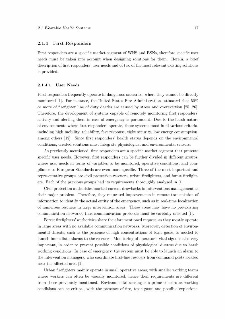
2.9 Garment solutions developed during the 3rd generation of the ProeTEXproject. From left to right: fireproof t-shirt or inner garment; boots; jacketor outer garment. Retrieved from [28]. . . . . . . . . . . . . . . . . . . . . . 18
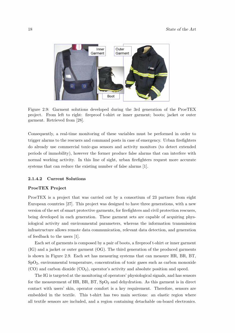
2.10 Information management network used in ProeTEX project. Retrievedfrom [1]. . . . . . . . . . . . . . . . . . . . . . . . . . . . . . . . . . . . . . . 19
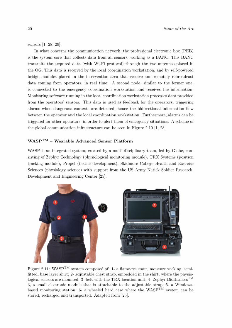
2.11 WASPTM system composed of: 1- a flame-resistant, moisture wicking, semi-fitted, base layer shirt; 2- adjustable chest strap, embedded in the shirt,where the physiological sensors are mounted; 3- belt with the TRX locationunit; 4- Zephyr BioHarnessTM 3, a small electronic module that is attach-able to the adjustable strap; 5- a Windows-based monitoring station; 6- awheeled hard case where the WASPTM system can be stored, recharged andtransported. Adapted from [25]. . . . . . . . . . . . . . . . . . . . . . . . . . 20
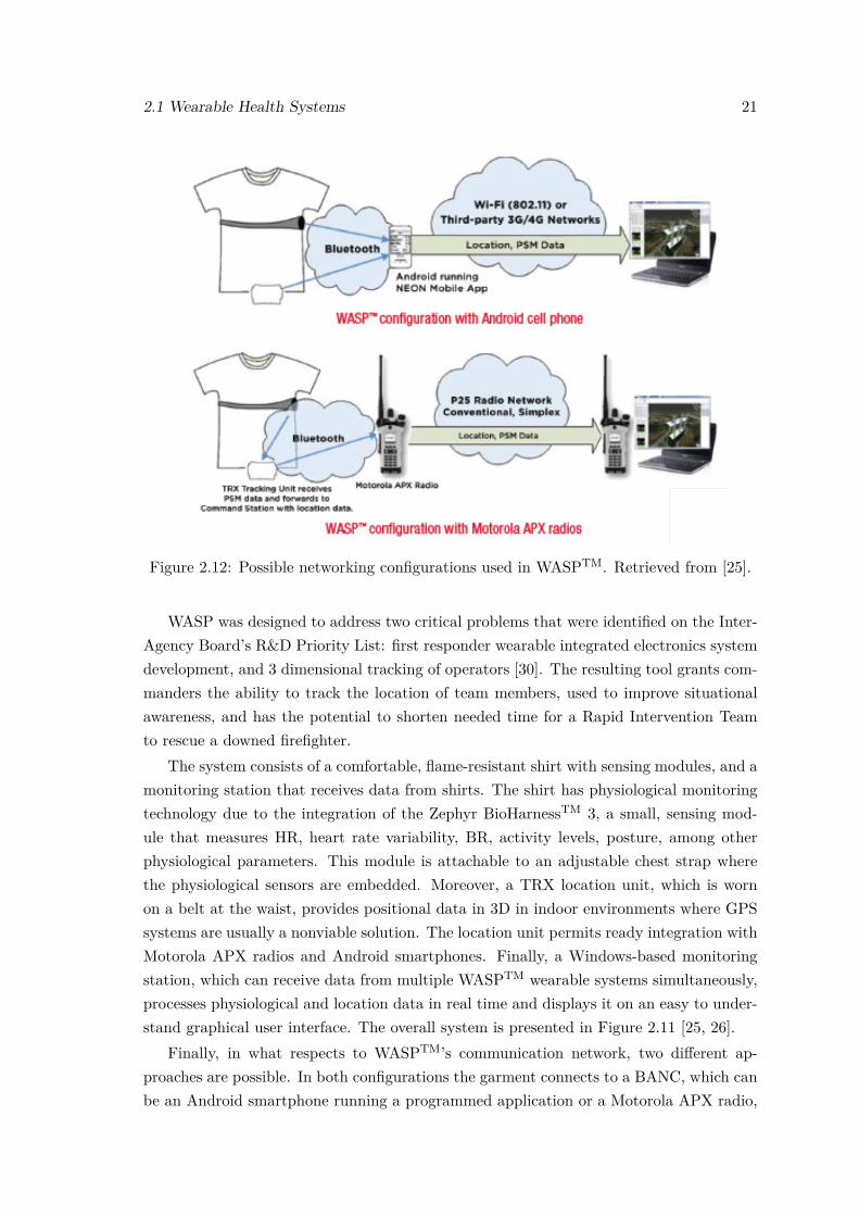
2.12 Possible networking configurations used in WASPTM. Retrieved from [25]. . 212.13 Wearable device market value from 2010 to 2018 (in million US dollars).
Retrieved from [33]. . . . . . . . . . . . . . . . . . . . . . . . . . . . . . . . 22
xi

xii LIST OF FIGURES
2.14 Projected sales of MEMS and sensors for wearable devices, until the yearof 2019. Sales are distributed per category of wearable device. Retrievedfrom [34]. . . . . . . . . . . . . . . . . . . . . . . . . . . . . . . . . . . . . . 23
2.15 Spectrum of applications for wearable technologies. Retrieved from [38]. . . 242.16 VitalJacket R© monitoring system by Biodevices SA. Adapted from [4, 65]. . 322.17 Evolution of VitalJacket R© into the VitalResponder monitoring system. Re-
trieved from [4]. . . . . . . . . . . . . . . . . . . . . . . . . . . . . . . . . . . 34
3.1 Component diagram of the framework which integrates this thesis’ work. . . 383.2 Detailed workflow of the work developed in this Master Thesis, in order to
accomplish the objective of giving not only more, but better information tofirst responders. . . . . . . . . . . . . . . . . . . . . . . . . . . . . . . . . . . 39
3.3 Schematic representation of the two-stage loop implementation of the Kalmanfilter. Adapted from [70]. . . . . . . . . . . . . . . . . . . . . . . . . . . . . 41
3.4 Schematic representation of the old system, and of the new system afterimplementing new sensors. On the top image, there is the old VitalJacketsystem which has only ECG and Actigraphy sensors. On the bottom, theVitalLogger system is represented, which has the new sensors for SpO2,ambient temperature and humidity. . . . . . . . . . . . . . . . . . . . . . . . 43
3.5 Schematic representation of a possible datagram sent by VL through Blue-tooth connectivity. For each sensor, a tag value must be sent previous toits data, in order to identify what data is present in each section of thedatagram. . . . . . . . . . . . . . . . . . . . . . . . . . . . . . . . . . . . . . 44
3.6 Test application displaying data and counters for the new implementedsensors. The images on the right show clearly that the SpO2 sensor sendsdata at a rate around five times higher than the ambient temperature andhumidity sensor, since the value in its counter is approximately five timesthe value in the other counters. . . . . . . . . . . . . . . . . . . . . . . . . . 45
3.7 Test application displaying the data sending rates obtained with the timerimplementation, the list of sensors being effectively used (placed below thetimers), and the possible cases for the SpO2 sensor. 1 - Full app interface;2 - No finger is placed in the sensor; 3 - The finger is placed correctly; 4 -The finger is misplaced, hence incorrect SpO2 measurements are acquired. . 46
3.8 Acquisition from VitalLogger prototype, executed with the Windows SDKapplication from Biodevices SA, and performed without a finger inserted inthe SpO2 sensor. . . . . . . . . . . . . . . . . . . . . . . . . . . . . . . . . . 47
3.9 Acquisition from VitalLogger prototype, executed with the Windows SDKapplication from Biodevices SA, and performed with a finger inserted in theSpO2 sensor. . . . . . . . . . . . . . . . . . . . . . . . . . . . . . . . . . . . 48
3.10 Schematic representation of the future system, with a modular architecture,that enables the expansion according to the sensing needs that might appearin the future. Here, a concept of master and slave is implemented, where allthe sensing modules (slaves) are connected to the master. Data sent fromthe slaves to the master can be processed and sent to the end user, whichis the Fire Chief. . . . . . . . . . . . . . . . . . . . . . . . . . . . . . . . . . 49
3.11 Hardware set used to simulate a system with modular architecture. 1 -MPLAB ICD 3 In-Circuit Debugger; 2 - Explorer 16 Development Boards,from Microchip; 3 - Logic debugging hardware unit. . . . . . . . . . . . . . 50
LIST OF FIGURES xiii
3.12 Schematic representation of a master connected to three slaves through theSPI bus. The bus has the SCLK (or CLK), MISO and MOSI lines, whichare shared by all slaves with the master, and the SS (or CS) lanes that arespecific to each slave. Retrieved from [72]. . . . . . . . . . . . . . . . . . . . 51
3.13 SPI protocol defined to use in the communication between the slaves andthe master in the modular system. . . . . . . . . . . . . . . . . . . . . . . . 52
3.14 A single section of the SPI communication between the master and theslave, with the MOSI, MISO, CLK, CS and DataReady lines observed inLogic v1.1.1.15. . . . . . . . . . . . . . . . . . . . . . . . . . . . . . . . . . . 52
3.15 View of the SPI communication between the master and the slave withthree different segments, with the MOSI, MISO, CLK, CS and DataReadylines observed in Logic v1.1.1.15. . . . . . . . . . . . . . . . . . . . . . . . . 53
3.16 Two different scenarios, exemplified with an ambient temperature signal,where the algorithm for data selection can work, and where different re-sponses are obtained. For temperatures above the higher threshold, analarm is triggered, and an algorithm starts working, which selects more orless samples of data depending if the signal is varying significantly (Signal1), or if it is relatively stabilized (Signal 2). . . . . . . . . . . . . . . . . . . 55
3.17 Basic workflow of the algorithm developed to detect significant changes insensed signals. . . . . . . . . . . . . . . . . . . . . . . . . . . . . . . . . . . . 57
3.18 Three-step process used to test and evaluate the algorithm with known sig-nals. A - classification’s ground truth, B - original signal, C - classificationobtained with the algorithm. . . . . . . . . . . . . . . . . . . . . . . . . . . 58
3.19 ROC curves obtained with the algorithm using a buffer with 20 samples,sample delays from 1 to 19 samples, and thresholds from 0.0001 to 10%.Sample delays over 10 samples have a notoriously prejudicial effect in theROC curve of the algorithm, and are displayed with circular markers toshow that behavior more intuitively. . . . . . . . . . . . . . . . . . . . . . . 60
3.20 True Positive Fraction (TPF) and False Positive Fraction (FPF) obtainedusing a buffer with a size of 5 samples, delays varied from 1 to 4 samples,and a threshold varied between 0.001 and 3% of the mean value of thesignal contained in the buffer. 1 - TPF increasing faster than FPF; 2 - FPFincreasing faster than TPF; 3 - TPF increases faster than FPF, followed bythe stabilization of both. . . . . . . . . . . . . . . . . . . . . . . . . . . . . . 61
3.21 Example of signal from the signal generator, analysed with the algorithmusing a threshold of 0.2% (threshold inside the plateau zone), and a delayof 1 and 7 samples. Selected data, for each delay, is presented in red. . . . . 62
3.22 ROC curves obtained with the algorithm using a buffer with 5 and 10samples, sample delays from 1 to 4 samples. . . . . . . . . . . . . . . . . . . 63
3.23 Schematic representation of the state machine developed to control thesensors. States 0 to 3 are generic states that every finite state machinemust have in order to control a sensor’s timestamp. Other extra statesmight need to be added for some specific sensors. . . . . . . . . . . . . . . . 65
3.24 Possible scenarios that can appear when using the control system. Times-tamps are marked in the timeline in yellow. On the first scenario, when thetimer t1 reaches the timestamp, the timestamp remains the same so datais sent. On the second one, when the timer t2 reaches the old timestamp,the timestamp has already changed to a smaller value so data is not sent. . 67
xiv LIST OF FIGURES
3.25 Demonstration of the implemented state machine, before implementing inthe firmware. The transition to State 3, which is triggered by pressing VJ’sbutton, was simulated by configuring a specific SpO2 value (20 in this case)to work as the button in the real system. . . . . . . . . . . . . . . . . . . . 68
3.26 Resampled rectal temperature signal and original estimated core tempera-ture signal, displayed in function of time. It is possible to observe that theresampled signal matches the original signal relatively closely, in terms ofits disposition in the time scale. . . . . . . . . . . . . . . . . . . . . . . . . . 72
3.27 Artifact creation at the beginning and end sections of the resampled signals,resulting from the usage of the resample function from MATLAB. . . . . . 72
3.28 Rectal temperature in function of heart rate, for the Active condition dataset. 74
3.29 Rectal temperature in function of heart rate, for the Control condition dataset. 74
3.30 Rectal temperature in function of heart rate, for the Passive condition dataset. 75
3.31 Rectal temperature and skin temperature measurements for the five differ-ent body sites, from one subject. While skin temperatures show a linearevolution with core temperature, their values remain below core tempera-ture during the whole experiment, for all subjects. . . . . . . . . . . . . . . 76
3.32 Core Temperature estimation and Heart Rate in function of time. Thisdata was obtained with a BioHarnessTM, and shows the tendency that coretemperature increases with heart rate. . . . . . . . . . . . . . . . . . . . . . 77
3.33 Test application running with the extended SDK, which is adapted to thenew sensors (SpO2, ambient temperature and relative humidity. The systemis capable of detecting the existing sensors, displaying them in a list (markedin red). If the smartphone is connected to a VitalJacket, the sensors in 2are shown, whereas if it is connected to a VitalLogger, the sensors in 2, 3and 4 are shown to the list. . . . . . . . . . . . . . . . . . . . . . . . . . . . 79
3.34 SPI communication between a fictitious VitalLogger module (slave) anda master. The sections of the datagram are aligned with the respectivebytes in the MISO channel. The second “data” segment corresponds to theambient temperature data, which is contained in two bytes of information. 80
3.35 Ambient temperature and SpO2 signals analysed with the developed algo-rithm. The original signal is presented in blue, and data that is consideredrelevant by the algorithm is presented in red. . . . . . . . . . . . . . . . . . 82
3.36 Demonstration of the control system that selects data, running on ambienttemperature signal. Below the threshold few samples are selected. Abovethe threshold the number of selected samples increases, with the number ofselected samples depending on whether the signal is changing significantlyor not. . . . . . . . . . . . . . . . . . . . . . . . . . . . . . . . . . . . . . . . 84
3.37 Demonstration of the mobile application with an alarm system implemented,that is triggered by ambient temperature. In this demonstration, the ap-plication was configured to trigger the alarm when ambient temperaturerose above 25 degrees Celsius. 1 - Overall interface of the application; 2 -Temperature status showed when temperature is below the threshold; 3 -Temperature status showed when temperature is above the threshold. . . . 85
LIST OF FIGURES xv
3.38 Comparison of core temperature obtained with the three different approaches:using a rectal probe (in red), using BioHarness (in green), and using theimplemented system (in blue). In this case, the implemented system worksquite well, following the trend of the rectal temperature. The drop in rectaltemperature around the 37th minute, marked with a black ellipse, was dueto problems with the probe, which had to be repositioned. . . . . . . . . . . 87
3.39 Comparison of core temperature obtained with the three different approaches:using a rectal probe (in red), using BioHarness (in green), and using theimplemented system (in blue). In this case, the implemented system worksvery badly, producing slight changes in the estimated core temperaturethroughout the signal. . . . . . . . . . . . . . . . . . . . . . . . . . . . . . . 87
3.40 Comparison of PSI computed with core temperature from three differentsources: rectal probe (in red), BioHarness (in green), and implemented sys-tem (in blue). In this case, PSI estimations remain close for core tempera-ture from all sources, with PSI obtained using core temperature estimatesfrom the implemented CT estimator being overestimated in the upper rangeof PSI values. . . . . . . . . . . . . . . . . . . . . . . . . . . . . . . . . . . . 89
3.41 Comparison of PSI computed with core temperature from three differentsources: rectal probe (in red), BioHarness (in green), and implementedsystem (in blue). In this case, PSI estimations are worse for both CTestimating systems, but while with CT estimations from BioHarness, PSIis constantly overestimated with an almost fixed offset, for the implementedCT estimator PSI overshoots in temperatures obtained during the exercisephase. . . . . . . . . . . . . . . . . . . . . . . . . . . . . . . . . . . . . . . . 90


List of Tables
3.1 Summary of the best F1 score for each delay, with its respective threshold,and of the algorithms’ mean Accuracy obtained at the same delay andthreshold. . . . . . . . . . . . . . . . . . . . . . . . . . . . . . . . . . . . . . 81
3.2 Mean Accuracy and F1 Score for ambient temperature and SpO2 signalsobtained with the VitalLogger. . . . . . . . . . . . . . . . . . . . . . . . . . 82
xvii


List of Abbreviations
6LoWPAN IPv6 over Low power Wireless Personal Area NetworksANS Autonomic Nervous SystemBAN Body Area NetworkBANC Body Area Network CoordinatorBP Blood PressureBPV Blood Pressure VariabilityBR Breathing RateBSN Body Sensor NetworkBT Body TemperatureCO Carbon MonoxideCO2 Carbon DioxideCRC Cyclic Redundancy CheckCT Core TemperatureECG ElectrocardiogramEEG ElectroencephalographyEMG ElectromyographyFFT Fast Fourier TransformFPF False Positive FractionGPS Global Positioning SystemGSR Galvanic Skin ResponseHMM Hidden Markov modelHR Heart RateHRV Heart Rate VariabilityIG Inner GarmentIP Inductive PlethysmographyI/O Input/OutputLED Light Emitting DiodeMEMS Microelectromechanical SystemsMINDS Miniaturized, Integrated, Networked, Digitalized and StandardizedNN Neural NetworkOG Outer GarmentPCG Phonocardiography
xix

xx List of Abbreviations
PHS Personal Health SystemsPSD Power Spectral DensityPSI Physiological Strain IndexPTT Pulse Transit TimePWV Pulse Wave VelocityRFID Radio-frequency IdentificationRMSE Root Mean Square ErrorROC Receiver Operating CharacteristicSDK Software Development KitSPI Serial Peripheral InterfaceSpO2 Blood Oxygen SaturationSVM Support Vector MachineTEB Thoracic Electrical BioimpedanceTPF True Positive FractionVL VitalLoggerWHS Wearable Health SystemsWSN Wireless Sensor Network
Chapter 1
Introduction
1.1 Background and Context
Technologic advances are constantly redefining healthcare, being personalized healthcarethe latest revolution in the healthcare domain. Ubiquitous computing and electronic tex-tiles, with the former resulting from the merging of two distinct areas, have led to thedevelopment of wearable systems capable of monitoring both vital and environmental pa-rameters. However, these systems face the enormous challenge of monitoring physiologicalstatus in a continuous, non-invasive and real-time manner. Moreover, these systems needto be integrated in communication network structures in order to enable control at agreater scale (e.g. multi-individual real-time monitoring).
While wearable technologies have been mostly designed for vital sign monitoring forclinical applications, these technologies are also useful to monitor first responders whilst inaction. As first responders frequently operate in hazardous environments, it is critical tomonitor both vital and environmental parameters, and to provide that information to theleaders in charge of operations. This information can make the difference by increasingtactical awareness and supporting critical decision making, allowing first responders tomaximize their efficacy while minimizing their own risk [1].
VitalResponder project is an example of a wearable monitoring system designed forfirst responders. Being an evolution of VitalJacket R©, VitalResponder has a wider range ofembedded sensors and accepts different external sensors that enable the measurement ofnot only vital but also environmental parameters, making it a resourceful tool capable ofdelivering reliable monitoring for first responders. VitalLogger is a prototype of a wearablehealth device that seeks to expand the sensing capabilities of the VitalJacket, and thatcan therefore be integrated in VitalResponder in the future.
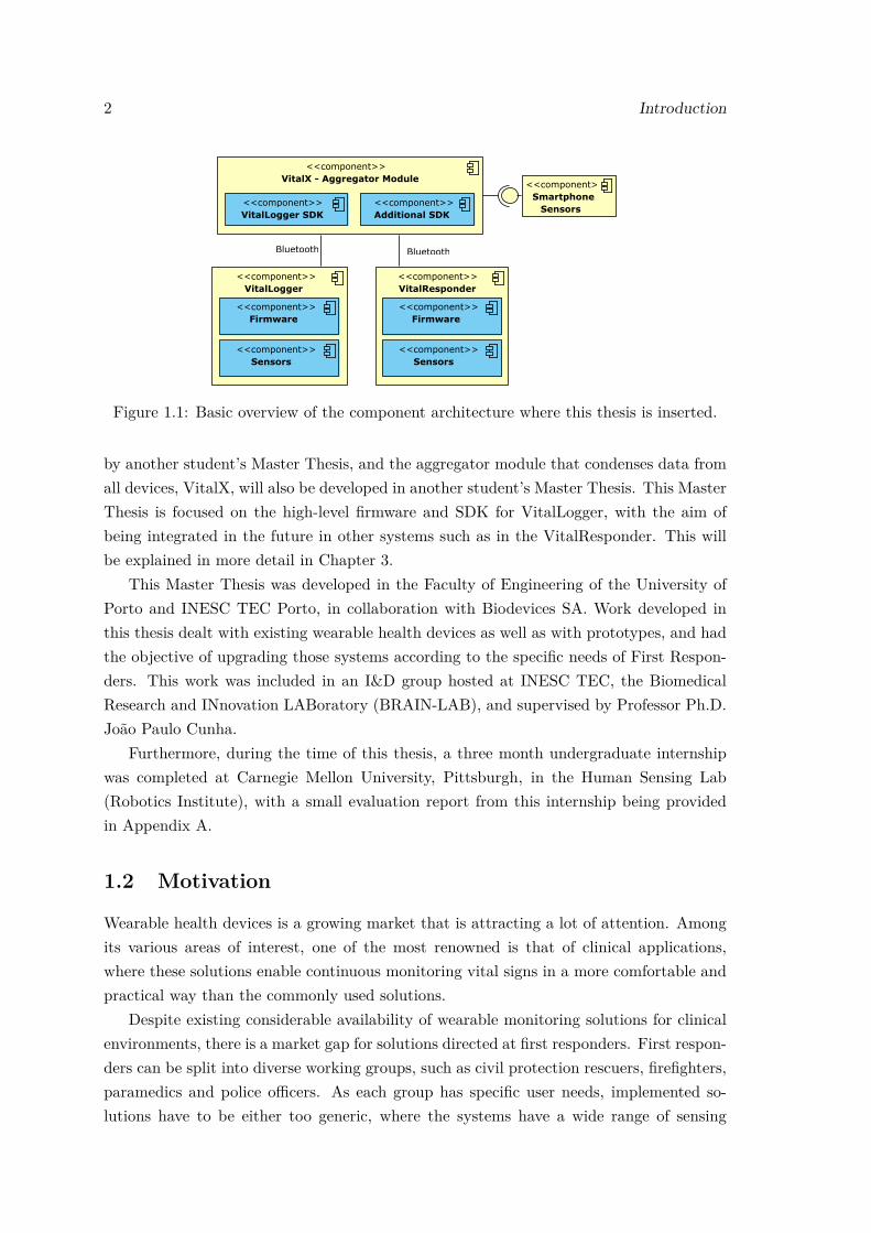
Work developed in this thesis is part of a greater project, which has contributionsfrom two other MSc students. The aim of this greater project is to aggregate data fromdiverse vital signs and environmental parameters. Figure 1.1 presents a basic view of thisproject, where the hardware and low-level firmware part of VitalLogger will be developed
1
2 Introduction
<<component>>VitalLogger
<<component>>Firmware
<<component>>Sensors
<<component>>VitalX - Aggregator Module
<<component>>VitalLogger SDK
<<component>>Additional SDK
<<component>>VitalResponder
<<component>>Firmware
<<component>>Sensors
<<component>>Smartphone
Sensors
BluetoothBluetooth
Figure 1.1: Basic overview of the component architecture where this thesis is inserted.
by another student’s Master Thesis, and the aggregator module that condenses data fromall devices, VitalX, will also be developed in another student’s Master Thesis. This MasterThesis is focused on the high-level firmware and SDK for VitalLogger, with the aim ofbeing integrated in the future in other systems such as in the VitalResponder. This willbe explained in more detail in Chapter 3.
This Master Thesis was developed in the Faculty of Engineering of the University ofPorto and INESC TEC Porto, in collaboration with Biodevices SA. Work developed inthis thesis dealt with existing wearable health devices as well as with prototypes, and hadthe objective of upgrading those systems according to the specific needs of First Respon-ders. This work was included in an I&D group hosted at INESC TEC, the BiomedicalResearch and INnovation LABoratory (BRAIN-LAB), and supervised by Professor Ph.D.João Paulo Cunha.
Furthermore, during the time of this thesis, a three month undergraduate internshipwas completed at Carnegie Mellon University, Pittsburgh, in the Human Sensing Lab(Robotics Institute), with a small evaluation report from this internship being providedin Appendix A.
1.2 Motivation
Wearable health devices is a growing market that is attracting a lot of attention. Amongits various areas of interest, one of the most renowned is that of clinical applications,where these solutions enable continuous monitoring vital signs in a more comfortable andpractical way than the commonly used solutions.
Despite existing considerable availability of wearable monitoring solutions for clinicalenvironments, there is a market gap for solutions directed at first responders. First respon-ders can be split into diverse working groups, such as civil protection rescuers, firefighters,paramedics and police officers. As each group has specific user needs, implemented so-lutions have to be either too generic, where the systems have a wide range of sensing
1.3 Objectives 3
capabilities to cover most of the needs of the different first responders, or be specific,being designed according to the specific needs of a given group of first responders.
Since this is an area of Biomedical Engineering that I find specially interesting, thisMaster Thesis is a great opportunity to apply my knowledge, even more when thereis collaboration with a portuguese company that works on biomedical system solutions,Biodevices SA.
Work developed in this thesis has the objective of implementing a new wearable healthdevice, that can be used as an extension of the existing solutions, and using that system tobuild new features that suit the specific needs of First Responders, more specifically thoseof firefighters. As firefighters are exposed to enormous stress and hazardous conditionswhile working, which can put their life at risk, this wearable device aims to make theirjob more secure, while also enabling them to improve their performance.
1.3 Objectives
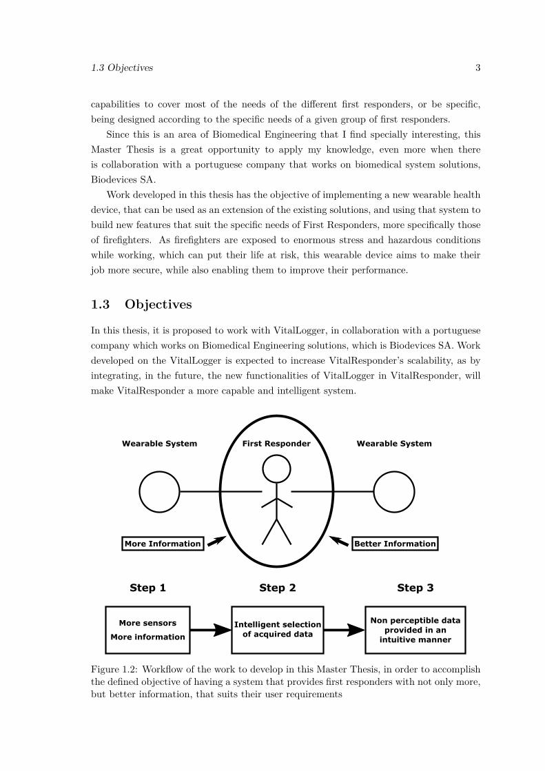
In this thesis, it is proposed to work with VitalLogger, in collaboration with a portuguesecompany which works on Biomedical Engineering solutions, which is Biodevices SA. Workdeveloped on the VitalLogger is expected to increase VitalResponder’s scalability, as byintegrating, in the future, the new functionalities of VitalLogger in VitalResponder, willmake VitalResponder a more capable and intelligent system.
More Information Better Information
Figure 1.2: Workflow of the work to develop in this Master Thesis, in order to accomplishthe defined objective of having a system that provides first responders with not only more,but better information, that suits their user requirements
4 Introduction
The objective of this thesis is centered on first responders, more specifically on firefight-ers, and it is to provide them not only with more information, but also better informationthat suits their specific requirements as a target group of wearable health systems. Sincefirst responders already use existing wearable solutions, such as VitalResponder, the ob-jective of this thesis can be accomplished by intervening on those wearable solutions,improving their sensing capacities, and the way they provide information to first respon-ders. As these wearable solutions are used by groups of first responders, in the case ofVitalResponder by groups of 5 firefighters, a lot of data is sent to the fire chief who iscommanding the firefighters, therefore it is crucial to provide only the necessary informa-tion, and in the most intuitive way possible. A schematic representation of the objectiveof this thesis is presented in the top part of Figure 1.2.
In order to meet these objectives, a workflow was designed to address different issuesof the final objective, and it is presented in Figure 1.2. This workflow was divided inthree steps. The first step consists in adapting a wearable system to newly implementedsensors, which enable the acquisition of novel physiological and environmental data, thusrendering more information.
Naturally associated with a system that senses more variables and gathers more data,comes the problem of having enormous amounts of information to provide to the firstresponders. Since it is important to provide only the most relevant information to the FireChief commanding the units, the second step aims to implement a system that intelligentlyselects data being acquired by the sensors, so that data redundancy is minimized and onlythe important information is given to the Fire Chief. Also in this step, and due to therequirements of first responders, information is provided in a more intuitive way to theFire Chief.
Finally, there is important information on the physiological status of first respondersthat is very hard, or even impossible to acquire using sensors, namely fatigue indexes.While this information can be extracted from other physiological parameters, easily sensedwith the current wearable system, this information is not perceptible for the user, so itmust be provided in an intuitive approach. Therefore, step 3 aims to implement a systemthat extracts important, non perceptible information from currently measured data, thatcan be provided to the Fire Chief in a way that can be intuitively analysed, and used tomanage human resources more efficiently.
With the final improved system, it is expected to be able to monitor more efficientlyfirst responders’ stress and fatigue, while these operate in critical scenarios.
1.4 Structure
This Master Thesis is structured in four chapters, including the present chapter of intro-duction. The second chapter contains a review of the state of the art. The first part ofthe state the art presents an overview of common wearable health systems (WHS), shows
1.5 Main Contributions 5
some of the existing wearable solutions, either in prototype phase or as a final productavailable in the market, both for clinical scenarios and for first responders. Moreover, thispart explores the specific needs of first responders in what concerns WHS and presents abrief vision of the WHS market.
Still in the second chapter, the second part of the state of the art presents a descriptionof the most important vital signs to be measured, and its respective sensing techniques.Finally, in the third part of the state of the art, VitalJacket R© technology and the Vital-Responder project are explained.
In the third chapter, the development phase of this thesis is presented. This chaptergoes through the three steps of the workflow presented in Figure 1.2. The first stepdescribes the adaptation of a wearable health system, VitalLogger, to newly implementedsensors, and also the preparation of the system for the addition, in the future, of othersensors that might be needed. The second step describes the implementation of a systemthat intelligently selects data acquired by sensors, so that only important information isused. This step reduces data redundancy, and, also in this step, selected data is providedto Fire Chiefs in a more intuitive way. Finally, the third step describes the developmentof a system that extracts important measures for first responders that are hard to, oreven cannot be acquired with sensors, but instead by exploring the relations betweenother physiological signals that are currently measured by the existing wearable solutions.These extracted measures can be used to provide relevant information about physiologicalstatus of the first responders, in a more intuitive approach.
In Chapter 4, which is the final chapter of this thesis, conclusions on the work devel-oped during this thesis are presented, as well as some suggestions for future work thatcan help improving even further the wearable sensing solutions that are VitalLogger andVitalResponder.
1.5 Main Contributions
This thesis had two main contributions, with the first one being related to the improvementof personal skills and knowledge, and the second one with the achievement of a morecapable and intelligent wearable system, that will hopefully, in the future, be placed inthe market as a biomedical engineering solution that is useful for first responders.
In what concerns the personal component, this thesis was a completely new challengethat presented many difficulties during its course, specially because it dealt with unknownareas that were not explored during the course of my studies. The opportunity to workwith employees from Biodevices SA was definitely a major asset, as it gave me the op-portunity to work with experienced people that used their experience to help me learningand improving. Their full support and commitment was crucial to help me understandingtheir systems, so that I could successfully develop my work. Moreover, the chance to leave

6 Introduction
the academia context, transition to the “real world”, and work on a product that mightbe used by other people in the future, greatly stimulated my personal growing.
In what regards the second contribution, the work developed in this thesis helpedcreating a new system that can be integrated with the existing ones, evolving them andmaking them more capable and intelligent. Hopefully, the implemented solution can, onthe one hand, provide firefighters with the necessary tools to make their job safer andincrease their performance. On the other hand, it is hoped that the implemented solutioncan help Biodevices SA expanding as a company in the future.
It must be referred that the collaboration with Biodevices SA was only possible becauseof the non-disclosure agreement with INESC TEC. This thesis was developed at INESCTEC, enabling greater proximity between INESC TEC and Biodevices SA, which in turnenabled easier knowledge transfer with Biodevices SA during this thesis.
Chapter 2
State of the Art
The development of innovative technologies and solutions is fostering progress in the con-cept of personalized healthcare. Due not only to the open-minded and technology con-suming nature of our society, but also to increasing interest in active health monitoring(self-tracking or quantified self) [2], citizens often avail of these developments as new tech-nologies end up being incorporated in a wide range of devices (e.g. smartphones).
Personal health systems (PHS), which is a recent concept (introduced in the 1990s),started being deployed due to the personalized healthcare approach. PHS are about plac-ing the individual citizen/patient right in the centre of the healthcare service, increasinghis power and likewise his responsibility in the management of his own health. The maingoal with PHS is to improve quality of care whilst reducing healthcare cost by having aproper and efficient use of technological capabilities [3].
Since its introduction, PHS have evolved and new specific categories were defined,namely wearable health systems. Wearable technologies possess particular interest andare herein explored as they may play a central role in the “quantified self” movement, andare a major asset in the personalized health challenge [4].
Wearable systems can be used to measure a wide range of signals, being it vital signsor even environment related variables (e.g. ambient temperature, humidity, etc). Thesesystems enable the acquisition of enormous amounts of data, from which precious infor-mation can be extracted directly. However, data sets can often be underexploited, as morecomplex information cannot be retrieved through the common, intuitive approaches. Inorder to explore data sets closer to their full extent, approaches based on data mining andmachine learning must be deployed.
In this chapter, a brief definition and overview of WHS will be presented, as wellas some existing products in the market, that are either targeted at healthcare or firstresponders market segments. Then, some of the most important vital signs that canbe acquired with wearable systems will be presented and explained, followed by a briefoverview on the fields of data mining and machine learning. Finally, VitalResponder,which is the system used in the work herein presented, will be briefly explained.
7
8 State of the Art
2.1 Wearable Health Systems
2.1.1 What are WHS?
Wearable systems can be defined, in a broad extent, as mobile electronic devices that canbe embedded, unobtrusively, in pieces of clothing and accessories, presenting the advantageof being operational and accessible without interfering with user activity [5]. While thesesystems can vary from micro sensors seamlessly integrated in textiles to head mounteddisplays [5], natural trend aims for miniaturized, integrated, networked, digitalized andstandardized (MINDS) devices [6].
These systems are extremely versatile and can be designed and developed specificallytargeting health related applications, thus fitting in the branch of WHS. Initial interestin WHS originated from the need to provide healthcare services outside hospitals andmonitor patients over extensive periods of time, whilst enabling patients to carry theirnormal life during the process [3]. With WHS enhancing healthcare services away frommedical facilities, a new paradigm in remote patient monitoring emerged.
Concerning current standards, monitoring devices can only be accepted and used forremote health monitoring if there is a comfortable sensing interface and easiness of useand customization. Moreover, the interface must combine continuous and real-time remotecontrol with perfect integration with users’ daily activities, without causing any interfer-ence whatsoever [7]. Textile approach, where sensors are embedded in pieces of clothing,allows long-term monitoring of patients at low cost, with the additional advantage ofenabling customization of sensor configuration according to each user needs [7]. Whileimplantable devices must be made with biocompatible materials in order to prevent re-jection by biological tissue, on-body devices are less prone to biocompatibility constraintsand have more flexibility in terms of materials. However, in order to provide safe long-termusage, it is recommended that on-body devices are also built with biocompatible materials[8].
In more advanced systems, which can be called intelligent WHS, integrated systemsare not only able to sense, process and communicate biomedical, biochemical and physicalparameters, but also capable of carrying out actions for the user, in case necessary [3].These systems increase user’s level of awareness and allow a better control of his ownhealth status by providing direct feedback, which is a crucial aspect when monitoringprofessional workers engaged in extreme environmental or stressful conditions, as is thecase of first responders [1, 7].
While there are some hurdles posed by technology that restrain implementation ofWHS, namely energy supply, power consumption, price and size of the devices, seamlessconnectivity or even interoperability [9], current progress has managed to partly addresssome of these issues. Regarding energy supply, which is currently a major handicap, devices
2.1 Wearable Health Systems 9
capable of harvesting energy from the surrounding environment have already started tobe studied and developed [10].
2.1.2 Communication in WHS
2.1.2.1 Networks in WHS
WHS are usually integrated in complex systems that comprise much more than wearablesensing technology. For instance, the increasing amount of sensors to be worn or implantedon the users, quite often at several different body parts, triggered the need to develop anetworking system capable of connecting this sensing “infrastructure” [10]. These networksare responsible for the data routing from sensors to the required destination [11]. In orderto fully understand how a WHS works, it is necessary to explore the networking domainwhere some interrelated notions arise, such as Body Area Network (BAN), Body SensorNetwork (BSN) and Wireless Sensor Network (WSN).
On the most general level, WSNs usually involve large numbers of low-cost, low-powerand tiny sensor nodes, with each node having a predefined set of components: sensors, mi-crocontroller, memory and radio transceiver [12]. This set of components grants each nodesensing, computing, storage and communication capabilities [8]. WSNs can be deployedfor environmental and health monitoring, battlefield surveillance, etc [12].
When various physiological and biomedical sensors are placed around the human bodyand interconnected through a network, a BAN is established. If each node from the con-necting network possesses a sensor or medical device with a sensing unit, we can thenrefer to it as a BSN rather than a BAN [10, 12]. Connecting all sensors by means of anetwork presents clear advantages, as it enables centralization of data gathered from dif-ferent sensors, which can be sent to external networks for remote processing. Furthermore,it enhances control, scheduling and programming of the whole system, which allows thesystem to adapt according to present body condition and external environment. Theseadvantages culminate in an optimization of resource usage [10].
Wireless communication is a key asset, and mandatory if we want systems to go mobileand ubiquitous. There is, however, a significant trade-off between energy consumptionand data volume to exchange, distance to communicate and needed uptime. The moredemanding the three former aspects, the lower is the expected battery life time, thuscommunication protocol selection is an important task that must be thoroughly analysedfor each situation [9].
Nevertheless, future prospects in next-generation WSNs are bright since they willhave two significant features: massive use of energy-efficient nodes that extend networks’working time, and dramatically increased network throughput that allows, for example,streaming of multiple high definition videos captured by optical sensors. These will proveuseful for applications aimed at first responders, such as large scale emergency rescuesduring natural disasters [13].
10 State of the Art
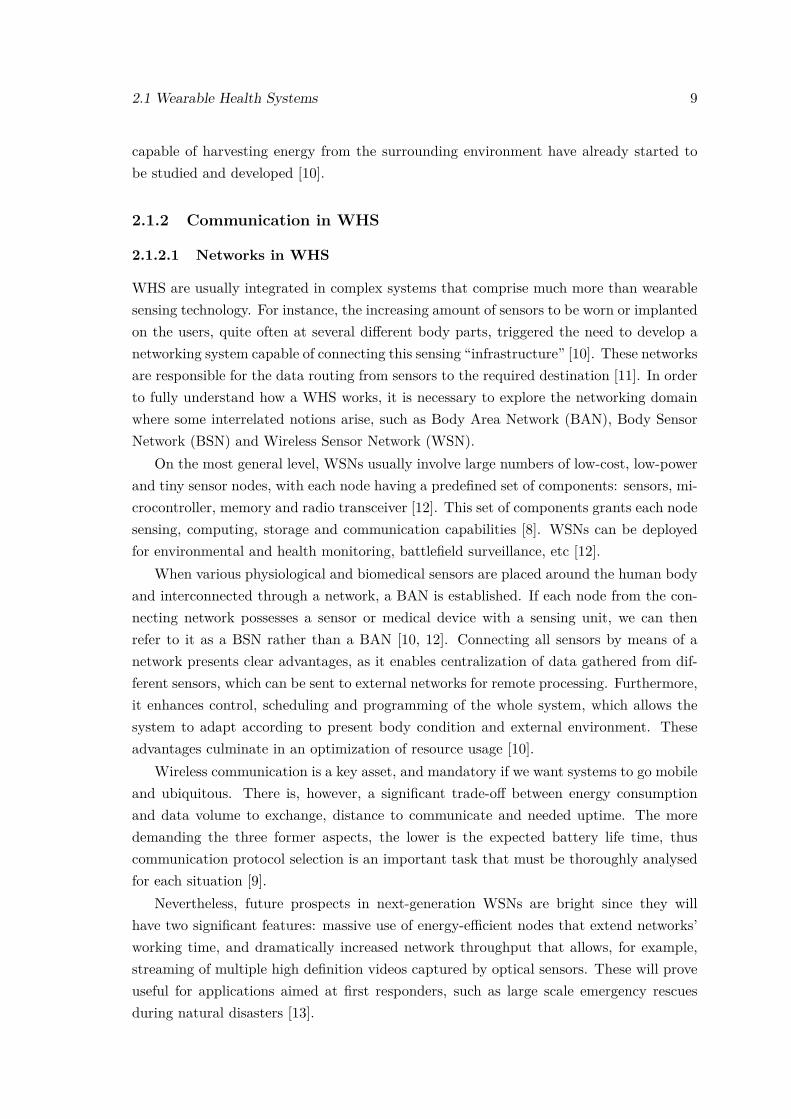
Figure 2.1: A three-tier system architecture of a BAN communication framework. Adaptedfrom [8, 11].
Bear in mind that WSNs designed for health related solutions, such as WHS, needspecial care in certain aspects, when compared to “general-purpose” WSNs. Some of themost important aspects to take into account are: devices have a very small form factor,which limits available energy resources; transmit power per node must be low to minimizeinterference and to cope with health concerns; devices must be robust against frequentchanges in network topology and channel variability, since these devices are located on thehuman body, where motion is frequently a reality; manipulated data is critical thus highreliability and low latency are required and, finally, devices are heterogeneous due to itsdifferent requirements in terms of resources, namely in data rate, power consumption andreliability [8].
2.1.2.2 System Architecture: A hierarchical view
When analysing WSNs regarding its organization, a hierarchical perspective of systems’architecture can be adopted. Most WSNs can be decomposed in a three-tier systemarchitecture [8, 11], as depicted in Figure 2.1. Evidently, tier composition may differslightly from the one in the presented scheme, with changes occurring according to thepurpose of the designed WSN (i.e. military WSNs differ from healthcare directed WSNs).
The lowest tier (tier 1) connects all sensor nodes within the BAN to a local collector,usually called BAN coordinator (BANC), where information collected from sensors is
2.1 Wearable Health Systems 11
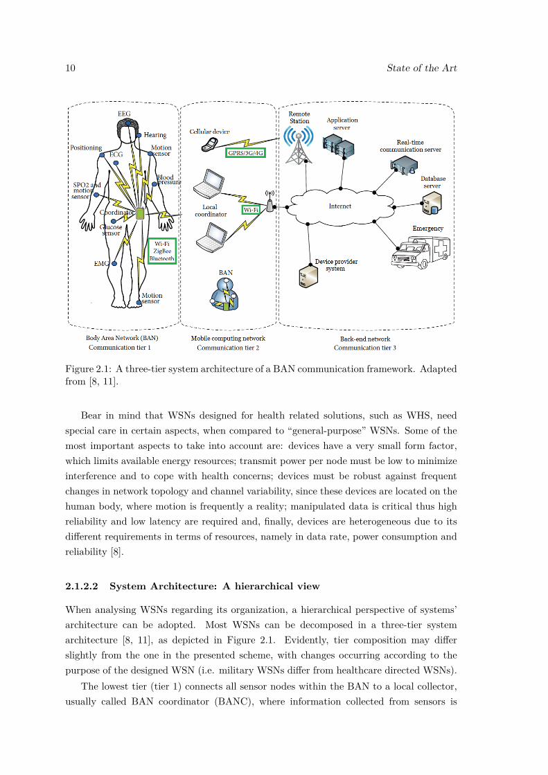
Figure 2.2: Representative scheme of a multihop communication process. Retrieved from[14].
centralized. The coordinator can be a device such as a smartphone or PDA [8]. Sincesensors in a BAN tend to have tiny dimensions and limited energy resources, it is wiseto route data into a coordinator with better technical resources, since it boosts systems’energy efficiency. During this routing procedure, nodes can forward information from andto other nodes, instead of sending it directly to the coordinator [11]. This process is calledmultihop communication and can be observed in Figure 2.2.
Some of the commonly used communication protocols in this tier are Bluetooth, Wi-Fi and ZigBee [8, 9]. ZigBee wireless technology operates on IEEE 802.15.4 and is astandard for robust, low-cost and low-power mesh networks [15, 16, 17]. This standard iswidely accepted and deployed as it enables multihop communication, thus being useful forBAN applications as aforementioned. It should be noted that, in this tier, communicationprotocol selection is paramount as it must take into account sensor heterogeneity, whilstsecuring reliable communication within the network.
In the intermediate layer (tier 2), the BANC can connect to multiple mobile computingplatforms, such as cellular devices, gateways and local coordinators. At this level, datacan be processed in structures such as the local coordinators, where relevant informationcan be extracted to assess and control tier 1 structures. It is also possible for BANCs toconnect to other BANCs, but in this case data cannot be forwarded to tier 3 unless thereceiving BANC connects and sends the data to a local coordinator, gateway or cellulardevice. In what concerns communication protocols, data can be routed through Bluetooth,Wi-Fi and ZigBee protocols [8, 11].
The last and upper level (tier 3) is considered the long distance communication level.Information is routed from tier 2 structures mainly through Wi-Fi protocol, but alsothrough GPRS, 3G and more recently 4G. Routed data is placed in IP-based networkswhere different structures can access, process and analyse it in real time [8, 11]. Relevantdata can be explored in order to control lower tier infrastructures.
Due to constant technologic evolution, wireless communication protocols describedwithin this architecture are not immutable, and other protocols such as Radio-frequencyIdentification (RFID) and IPv6 over Low power Wireless Personal Area Networks (6LoW-
12 State of the Art
PAN) can also be used [9]. More recently, great interest has been placed on IEEE 802.11ac,which is a standard of the Wi-Fi family. This new standard allows increased link through-put up to 1 Gigabits per second, bringing exciting prospects for next-generation WSNs[13].
Some frameworks go even further and categorize devices in the communication frame-work considering their energy levels, with type 1 devices being directly connected to powersources, type 2 having replaceable batteries and type 3 non replaceable batteries [11].
2.1.3 Current Solutions
WHS are used in a broad scope of applications, comprising healthcare and military appli-cations, or even personal usage considering the wide spreading paradigm of the quantifiedself. A list of various wearable biomedical measurement systems can be seen in [18].Herein, some of the existing WHS solutions implementing different measurement systems,either in prototype stage or already in the market, are briefly presented.
2.1.3.1 Prototypes
ANTREC Project
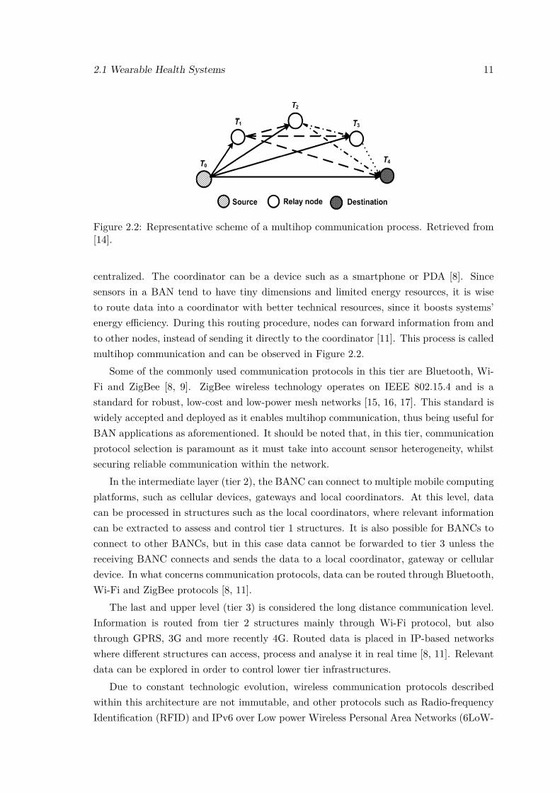
ANTREC Project is an ongoing project developed in the scope of the Spanish FutureCombatant Program (ComFut), a program created by the Spanish Ministry of Defense.This project seeks to develop a set of sensorized garments capable of measuring, non-invasively, galvanic skin response (GSR), body temperature (BT), ECG, thoracic electricalbioimpedance (TEB) and voice recording for speech analysis, in order to assess throughreal-time monitoring the stress levels of combatants [19].
Figure 2.3: Schematics of the sensorized glove. (a) Upper view. (b) Cross-sectional viewof the glove at the proximal phalanx in a perpendicular plane to the palm. (c) Palm view.(d) Prototype of the sensorized glove connected to the measuring unit fastened to thewristband. Adapted from [19].
2.1 Wearable Health Systems 13
(a) Upper arm strap. (b) Chest strap system for ECG and TEBelectrodes.
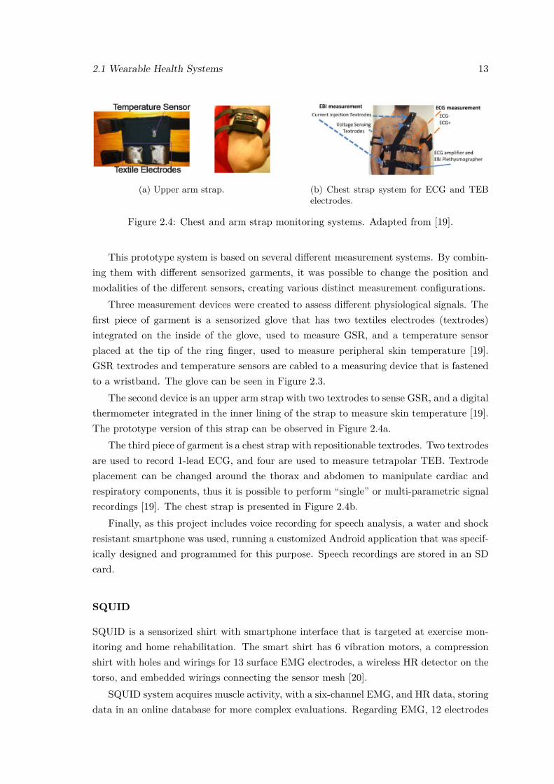
Figure 2.4: Chest and arm strap monitoring systems. Adapted from [19].
This prototype system is based on several different measurement systems. By combin-ing them with different sensorized garments, it was possible to change the position andmodalities of the different sensors, creating various distinct measurement configurations.
Three measurement devices were created to assess different physiological signals. Thefirst piece of garment is a sensorized glove that has two textiles electrodes (textrodes)integrated on the inside of the glove, used to measure GSR, and a temperature sensorplaced at the tip of the ring finger, used to measure peripheral skin temperature [19].GSR textrodes and temperature sensors are cabled to a measuring device that is fastenedto a wristband. The glove can be seen in Figure 2.3.
The second device is an upper arm strap with two textrodes to sense GSR, and a digitalthermometer integrated in the inner lining of the strap to measure skin temperature [19].The prototype version of this strap can be observed in Figure 2.4a.
The third piece of garment is a chest strap with repositionable textrodes. Two textrodesare used to record 1-lead ECG, and four are used to measure tetrapolar TEB. Textrodeplacement can be changed around the thorax and abdomen to manipulate cardiac andrespiratory components, thus it is possible to perform “single” or multi-parametric signalrecordings [19]. The chest strap is presented in Figure 2.4b.
Finally, as this project includes voice recording for speech analysis, a water and shockresistant smartphone was used, running a customized Android application that was specif-ically designed and programmed for this purpose. Speech recordings are stored in an SDcard.
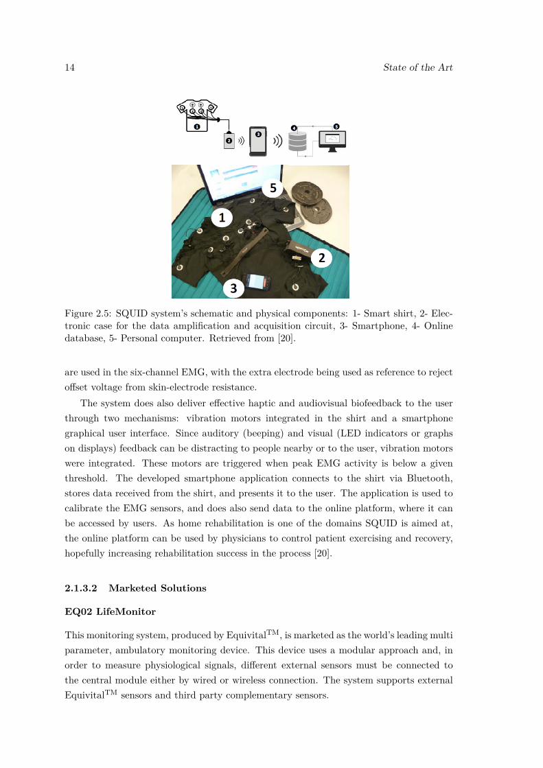
SQUID
SQUID is a sensorized shirt with smartphone interface that is targeted at exercise mon-itoring and home rehabilitation. The smart shirt has 6 vibration motors, a compressionshirt with holes and wirings for 13 surface EMG electrodes, a wireless HR detector on thetorso, and embedded wirings connecting the sensor mesh [20].
SQUID system acquires muscle activity, with a six-channel EMG, and HR data, storingdata in an online database for more complex evaluations. Regarding EMG, 12 electrodes
14 State of the Art
Figure 2.5: SQUID system’s schematic and physical components: 1- Smart shirt, 2- Elec-tronic case for the data amplification and acquisition circuit, 3- Smartphone, 4- Onlinedatabase, 5- Personal computer. Retrieved from [20].
are used in the six-channel EMG, with the extra electrode being used as reference to rejectoffset voltage from skin-electrode resistance.
The system does also deliver effective haptic and audiovisual biofeedback to the userthrough two mechanisms: vibration motors integrated in the shirt and a smartphonegraphical user interface. Since auditory (beeping) and visual (LED indicators or graphson displays) feedback can be distracting to people nearby or to the user, vibration motorswere integrated. These motors are triggered when peak EMG activity is below a giventhreshold. The developed smartphone application connects to the shirt via Bluetooth,stores data received from the shirt, and presents it to the user. The application is used tocalibrate the EMG sensors, and does also send data to the online platform, where it canbe accessed by users. As home rehabilitation is one of the domains SQUID is aimed at,the online platform can be used by physicians to control patient exercising and recovery,hopefully increasing rehabilitation success in the process [20].
2.1.3.2 Marketed Solutions
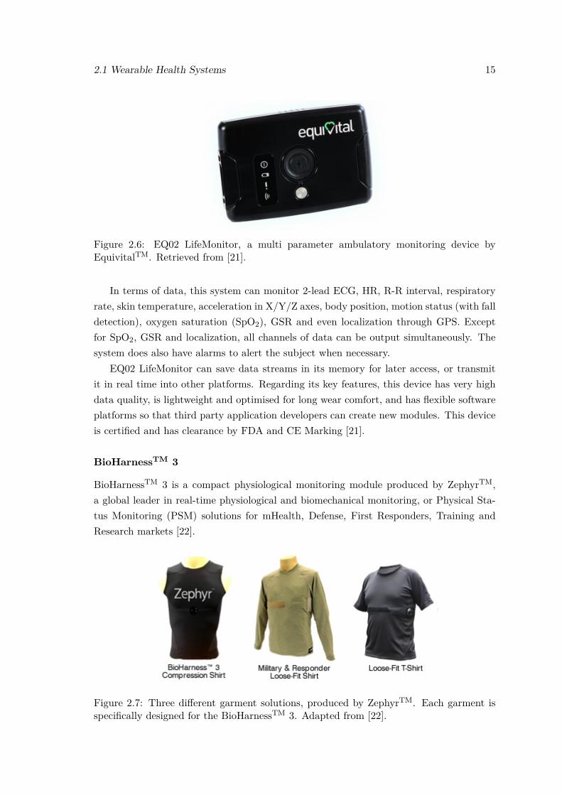
EQ02 LifeMonitor
This monitoring system, produced by EquivitalTM, is marketed as the world’s leading multiparameter, ambulatory monitoring device. This device uses a modular approach and, inorder to measure physiological signals, different external sensors must be connected tothe central module either by wired or wireless connection. The system supports externalEquivitalTM sensors and third party complementary sensors.
2.1 Wearable Health Systems 15
Figure 2.6: EQ02 LifeMonitor, a multi parameter ambulatory monitoring device byEquivitalTM. Retrieved from [21].
In terms of data, this system can monitor 2-lead ECG, HR, R-R interval, respiratoryrate, skin temperature, acceleration in X/Y/Z axes, body position, motion status (with falldetection), oxygen saturation (SpO2), GSR and even localization through GPS. Exceptfor SpO2, GSR and localization, all channels of data can be output simultaneously. Thesystem does also have alarms to alert the subject when necessary.
EQ02 LifeMonitor can save data streams in its memory for later access, or transmitit in real time into other platforms. Regarding its key features, this device has very highdata quality, is lightweight and optimised for long wear comfort, and has flexible softwareplatforms so that third party application developers can create new modules. This deviceis certified and has clearance by FDA and CE Marking [21].
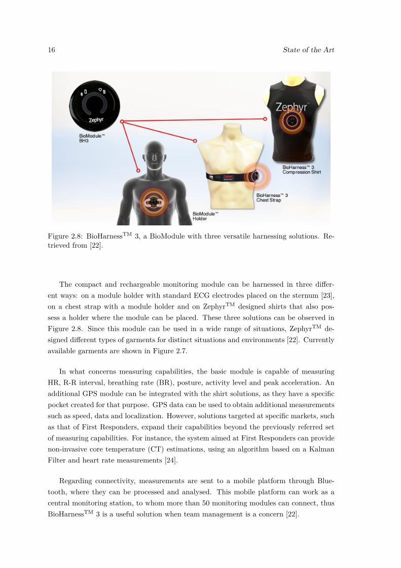
BioHarnessTM 3
BioHarnessTM 3 is a compact physiological monitoring module produced by ZephyrTM,a global leader in real-time physiological and biomechanical monitoring, or Physical Sta-tus Monitoring (PSM) solutions for mHealth, Defense, First Responders, Training andResearch markets [22].
Figure 2.7: Three different garment solutions, produced by ZephyrTM. Each garment isspecifically designed for the BioHarnessTM 3. Adapted from [22].
16 State of the Art
Figure 2.8: BioHarnessTM 3, a BioModule with three versatile harnessing solutions. Re-trieved from [22].
The compact and rechargeable monitoring module can be harnessed in three differ-ent ways: on a module holder with standard ECG electrodes placed on the sternum [23],on a chest strap with a module holder and on ZephyrTM designed shirts that also pos-sess a holder where the module can be placed. These three solutions can be observed inFigure 2.8. Since this module can be used in a wide range of situations, ZephyrTM de-signed different types of garments for distinct situations and environments [22]. Currentlyavailable garments are shown in Figure 2.7.
In what concerns measuring capabilities, the basic module is capable of measuringHR, R-R interval, breathing rate (BR), posture, activity level and peak acceleration. Anadditional GPS module can be integrated with the shirt solutions, as they have a specificpocket created for that purpose. GPS data can be used to obtain additional measurementssuch as speed, data and localization. However, solutions targeted at specific markets, suchas that of First Responders, expand their capabilities beyond the previously referred setof measuring capabilities. For instance, the system aimed at First Responders can providenon-invasive core temperature (CT) estimations, using an algorithm based on a KalmanFilter and heart rate measurements [24].
Regarding connectivity, measurements are sent to a mobile platform through Blue-tooth, where they can be processed and analysed. This mobile platform can work as acentral monitoring station, to whom more than 50 monitoring modules can connect, thusBioHarnessTM 3 is a useful solution when team management is a concern [22].
2.1 Wearable Health Systems 17
2.1.4 First Responders
First responders are a specific market segment of WHS and BSNs, therefore specific userneeds must be taken into account when designing solutions for them. Herein, a briefdescription of first responders’ user needs and of two of the most relevant existing solutionsis provided.
2.1.4.1 User Needs
First responders frequently operate in dangerous scenarios, where they cannot be directlymonitored [1]. For instance, the United States Fire Administration estimated that 50%or more of firefighter line of duty deaths are caused by stress and overexertion [25, 26].Therefore, the development of systems capable of remotely monitoring first responders’activity and alerting them in case of emergency is paramount. Due to the harsh natureof environments where first responders operate, these systems must fulfil various criteria,including high mobility, reliability, fast response, tight security, low energy consumption,among others [12]. Since first responders’ health status depends on the environmentalconditions, created solutions must integrate physiological and environmental sensors.
As previously mentioned, first responders are a specific market segment that presentsspecific user needs. However, first responders can be further divided in different groups,where user needs in terms of variables to be monitored, operative conditions, and com-pliance to European Standards are even more specific. Three of the most important andrepresentative groups are civil protection rescuers, urban firefighters, and forest firefight-ers. Each of the previous groups had its requirements thoroughly analysed in [1].
Civil protection authorities marked current drawbacks in interventions management astheir major problem. Therefore, they requested improvements in remote transmission ofinformation to identify the actual entity of the emergency, such as in real-time localizationof numerous rescuers in large intervention areas. These areas may have no pre-existingcommunication networks, thus communication protocols must be carefully selected [1].
Forest firefighters’ authorities share the aforementioned request, as they mostly operatein large areas with no available communication networks. Moreover, detection of environ-mental threats, such as the presence of high concentrations of toxic gases, is needed tolaunch immediate alarms to the rescuers. Monitoring of operators’ vital signs is also veryimportant, in order to prevent possible conditions of physiological distress due to harshworking conditions. In case of emergency, the system must be able to launch an alarm tothe intervention managers, who coordinate first-line rescuers from command posts locatednear the affected area [1].
Urban firefighters mainly operate in small operative areas, with smaller working teamswhere workers can often be visually monitored, hence their requirements are differentfrom those previously mentioned. Environmental sensing is a prime concern as workingconditions can be critical, with the presence of fire, toxic gases and possible explosions.
18 State of the Art
Figure 2.9: Garment solutions developed during the 3rd generation of the ProeTEXproject. From left to right: fireproof t-shirt or inner garment; boots; jacket or outergarment. Retrieved from [28].
Consequently, a real-time monitoring of these variables must be performed in order totrigger alarms to the rescuers and command posts in case of emergency. Urban firefightersdo already use commercial toxic-gas sensors and activity monitors (to detect extendedperiods of immobility), however the former produce false alarms that can interfere withnormal working activity. In this line of sight, urban firefighters request more accuratesystems that can reduce the existing number of false alarms [1].
2.1.4.2 Current Solutions
ProeTEX Project
ProeTEX is a project that was carried out by a consortium of 23 partners from eightEuropean countries [27]. This project was designed to have three generations, with a newversion of the set of smart protective garments, for firefighters and civil protection rescuers,being developed in each generation. These garment sets are capable of acquiring phys-iological activity and environmental parameters, whereas the information transmissioninfrastructure allows remote data communication, relevant data detection, and generationof feedback to the users [1].
Each set of garments is composed by a pair of boots, a fireproof t-shirt or inner garment(IG) and a jacket or outer garment (OG). The third generation of the produced garmentsis shown in Figure 2.9. Each set has measuring systems that can measure HR, BR, BT,SpO2, environmental temperature, concentration of toxic gases such as carbon monoxide(CO) and carbon dioxide (CO2), operator’s activity and absolute position and speed.
The IG is targeted at the monitoring of operators’ physiological signals, and has sensorsfor the measurement of HR, BR, BT, SpO2 and dehydration. As this garment is in directcontact with users’ skin, operator comfort is a key requirement. Therefore, sensors areembedded in the textile. This t-shirt has two main sections: an elastic region whereall textile sensors are included, and a region containing detachable on-board electronics.
2.1 Wearable Health Systems 19
Figure 2.10: Information management network used in ProeTEX project. Retrieved from[1].
Textile-conductive cables are integrated in the shirt to connect the textile sensors andelectrodes to the electronic modules. The detachable on-board electronics acquire signalsfrom the sensors, which are then forwarded into a BANC placed in the OG [1, 28, 29].
The boots satisfy EU standards and have integrated sensors and energy harvestingelements. A CO2 sensor is placed in an electronic module in the boots as this gas isheavier than air, and starts to accumulate at ground level. The CO2 module processesacquired data and sends it to the BANC through a ZigBee module [1, 28].
The OG includes the measuring systems for assessing operator activity status andmonitoring the surrounding environment. This piece of garment is produced in three con-figurations depending on the targeted users: civil protection rescuers, forest firefightersand urban firefighters. All configurations possess two triaxial accelerometers, a textile mo-tion sensor, a CO sensor and an external temperature sensor. Since CO is an extremelytoxic gas with density comparable to air, the CO sensor module is placed near the user’smouth and nose, in the OG lapel. Forest firefighters and civil protection rescuers have anintegrated GPS module, whereas urban firefighters do not. As urban firefighters operateinside buildings, where reliable GPS signals are rarely available, there is no point in in-tegrating a GPS module in their garments. Additionally, a heat-flux sensor was includedin urban and forest firefighter’s OG, to prevent operators’ sudden uniform burning, andan alarm module was also integrated to launch visual and acoustic warnings when criti-cal situations are detected by the sensors. Gathered data is sent to the BANC, which isplaced in the OG. Finally, the OG has two antennas that are connected to the BANC.These antennas are responsible for the wireless transmission of the data acquired by the
20 State of the Art
sensors [1, 28, 29].In what concerns the communication network, the professional electronic box (PEB)
is the system core that collects data from all sensors, working as a BANC. This BANCtransmits the acquired data (with Wi-Fi protocol) through the two antennas placed inthe OG. This data is received by the local coordination workstation, and by self-poweredbridge modules placed in the intervention area that receive and remotely rebroadcastdata coming from operators, in real time. A second node, similar to the former one,is connected to the emergency coordination workstation and receives the information.Monitoring software running in the local coordination workstation processes data providedfrom the operators’ sensors. This data is used as feedback for the operators, triggeringalarms when dangerous contexts are detected, hence the bidirectional information flowbetween the operator and the local coordination workstation. Furthermore, alarms can betriggered for other operators, in order to alert them of emergency situations. A scheme ofthe global communication infrastructure can be seen in Figure 2.10 [1, 28].
WASPTM – Wearable Advanced Sensor Platform
WASP is an integrated system, created by a multi-disciplinary team, led by Globe, con-sisting of Zephyr Technology (physiological monitoring module), TRX Systems (positiontracking module), Propel (textile development), Skidmore College Health and ExerciseSciences (physiology science) with support from the US Army Natick Soldier Research,Development and Engineering Center [25].
Figure 2.11: WASPTM system composed of: 1- a flame-resistant, moisture wicking, semi-fitted, base layer shirt; 2- adjustable chest strap, embedded in the shirt, where the physio-logical sensors are mounted; 3- belt with the TRX location unit; 4- Zephyr BioHarnessTM
3, a small electronic module that is attachable to the adjustable strap; 5- a Windows-based monitoring station; 6- a wheeled hard case where the WASPTM system can bestored, recharged and transported. Adapted from [25].
2.1 Wearable Health Systems 21
Figure 2.12: Possible networking configurations used in WASPTM. Retrieved from [25].
WASP was designed to address two critical problems that were identified on the Inter-Agency Board’s R&D Priority List: first responder wearable integrated electronics systemdevelopment, and 3 dimensional tracking of operators [30]. The resulting tool grants com-manders the ability to track the location of team members, used to improve situationalawareness, and has the potential to shorten needed time for a Rapid Intervention Teamto rescue a downed firefighter.
The system consists of a comfortable, flame-resistant shirt with sensing modules, and amonitoring station that receives data from shirts. The shirt has physiological monitoringtechnology due to the integration of the Zephyr BioHarnessTM 3, a small, sensing mod-ule that measures HR, heart rate variability, BR, activity levels, posture, among otherphysiological parameters. This module is attachable to an adjustable chest strap wherethe physiological sensors are embedded. Moreover, a TRX location unit, which is wornon a belt at the waist, provides positional data in 3D in indoor environments where GPSsystems are usually a nonviable solution. The location unit permits ready integration withMotorola APX radios and Android smartphones. Finally, a Windows-based monitoringstation, which can receive data from multiple WASPTM wearable systems simultaneously,processes physiological and location data in real time and displays it on an easy to under-stand graphical user interface. The overall system is presented in Figure 2.11 [25, 26].
Finally, in what respects to WASPTM’s communication network, two different ap-proaches are possible. In both configurations the garment connects to a BANC, which canbe an Android smartphone running a programmed application or a Motorola APX radio,
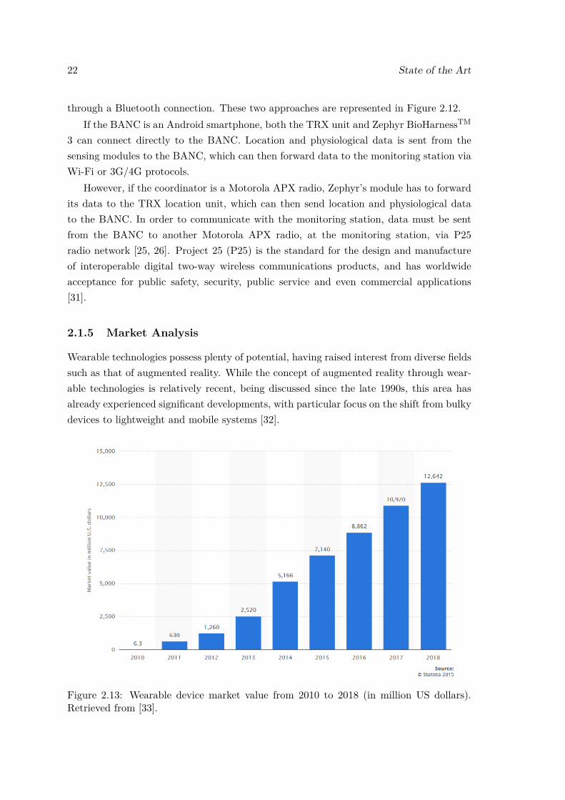
22 State of the Art
through a Bluetooth connection. These two approaches are represented in Figure 2.12.If the BANC is an Android smartphone, both the TRX unit and Zephyr BioHarnessTM
3 can connect directly to the BANC. Location and physiological data is sent from thesensing modules to the BANC, which can then forward data to the monitoring station viaWi-Fi or 3G/4G protocols.
However, if the coordinator is a Motorola APX radio, Zephyr’s module has to forwardits data to the TRX location unit, which can then send location and physiological datato the BANC. In order to communicate with the monitoring station, data must be sentfrom the BANC to another Motorola APX radio, at the monitoring station, via P25radio network [25, 26]. Project 25 (P25) is the standard for the design and manufactureof interoperable digital two-way wireless communications products, and has worldwideacceptance for public safety, security, public service and even commercial applications[31].
2.1.5 Market Analysis
Wearable technologies possess plenty of potential, having raised interest from diverse fieldssuch as that of augmented reality. While the concept of augmented reality through wear-able technologies is relatively recent, being discussed since the late 1990s, this area hasalready experienced significant developments, with particular focus on the shift from bulkydevices to lightweight and mobile systems [32].
Figure 2.13: Wearable device market value from 2010 to 2018 (in million US dollars).Retrieved from [33].
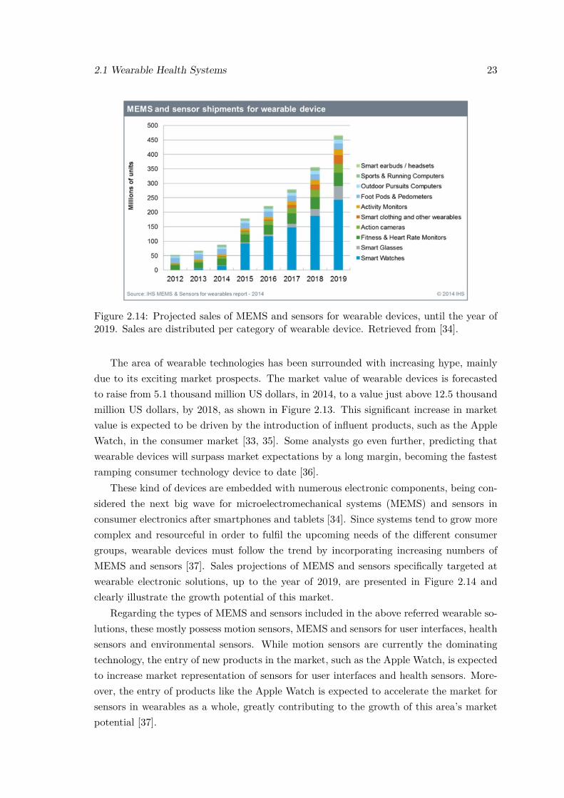
2.1 Wearable Health Systems 23
Figure 2.14: Projected sales of MEMS and sensors for wearable devices, until the year of2019. Sales are distributed per category of wearable device. Retrieved from [34].
The area of wearable technologies has been surrounded with increasing hype, mainlydue to its exciting market prospects. The market value of wearable devices is forecastedto raise from 5.1 thousand million US dollars, in 2014, to a value just above 12.5 thousandmillion US dollars, by 2018, as shown in Figure 2.13. This significant increase in marketvalue is expected to be driven by the introduction of influent products, such as the AppleWatch, in the consumer market [33, 35]. Some analysts go even further, predicting thatwearable devices will surpass market expectations by a long margin, becoming the fastestramping consumer technology device to date [36].
These kind of devices are embedded with numerous electronic components, being con-sidered the next big wave for microelectromechanical systems (MEMS) and sensors inconsumer electronics after smartphones and tablets [34]. Since systems tend to grow morecomplex and resourceful in order to fulfil the upcoming needs of the different consumergroups, wearable devices must follow the trend by incorporating increasing numbers ofMEMS and sensors [37]. Sales projections of MEMS and sensors specifically targeted atwearable electronic solutions, up to the year of 2019, are presented in Figure 2.14 andclearly illustrate the growth potential of this market.
Regarding the types of MEMS and sensors included in the above referred wearable so-lutions, these mostly possess motion sensors, MEMS and sensors for user interfaces, healthsensors and environmental sensors. While motion sensors are currently the dominatingtechnology, the entry of new products in the market, such as the Apple Watch, is expectedto increase market representation of sensors for user interfaces and health sensors. More-over, the entry of products like the Apple Watch is expected to accelerate the market forsensors in wearables as a whole, greatly contributing to the growth of this area’s marketpotential [37].
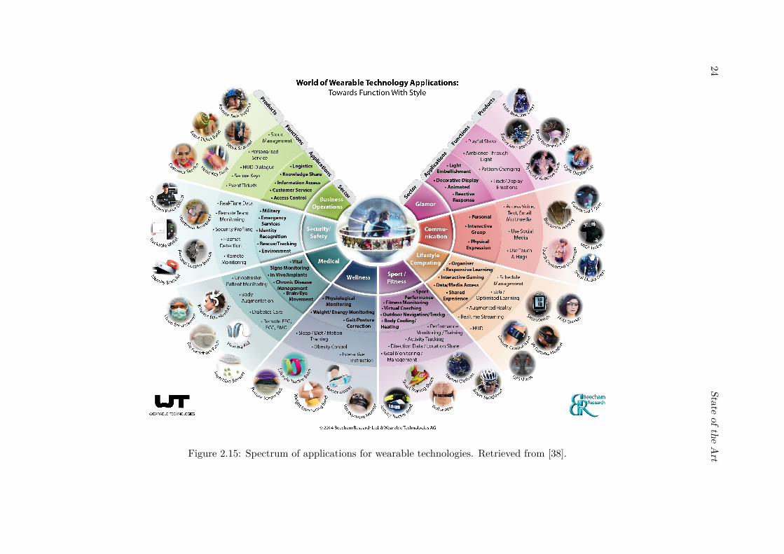
24State
oftheArtFigure 2.15: Spectrum of applications for wearable technologies. Retrieved from [38].
2.2 Vital Signs 25
More recently, wireless charging technologies have been developed that allow the charg-ing of batteries wirelessly, naturally presenting utmost interest for the domain of wearablemonitoring devices. While this technology might take some time to effectively get intothe market, the integration of such technology in wearable electronic devices is expectedto further increase this field’s market potential [35, 39].
In what concerns possible applications for wearable technologies, these are alreadydeployed in various fields of interest. Figure 2.15 summarizes the most important sectors,applications, functions and products in wearable technologies. In spite of having security(military applications) and medical fields as the most relevant sectors until recent years,latest technological developments have shifted the spotlight to consumer market, whichmostly comprises the areas of sports, fitness and infotainment [32].
In this work, interest is focused on first responders’ market segment, which fits in thesecurity/safety sector. While no values regarding market size of wearable technologiesfor first responders were found in literature, the market size for first responders and lawenforcement robotics, which is related to that of wearable technologies, is said to begrowing to 3.7 billion dollars by 2016 [40]. Since market value of the wearable devicemarket has been increasing, and is predicted to explode in the near-future, this workpresents increased importance, for it addresses a great business opportunity.
2.2 Vital Signs
The recent paradigm of pHealth (personalized health) has brought portable and wear-able technology to the domain of medical systems, and with the shaping of personalizedhealthcare, new requirements arose. Current and future systems have to be able to monitorusers’ health condition on a continuous and non-invasive basis, whilst providing feedbackto users and/or medical professionals when these systems are used in a medical context[10].
Depending on the intended purpose, a person’s health status can be measured throughthe monitoring of various vital signs. The most important vital signs for medical systems,as well as those required in first responders’ systems, are identified and briefly explainedin this chapter.
2.2.1 Vital Signs in the Medical Context
Wearable health systems face the everlasting challenge of measuring physiological pa-rameters through non-invasive and continuous approaches. Current monitoring systemsmanage to acquire diverse vital signs non-invasively, with major vital signs being HR,ECG, BP, BR, SpO2 [10] and BT [41]. Gathered information can be used for possibledisease prediction or prevention [10].
Emerging technologies open prospects for new possibilities, thus leading to the devel-opment of new monitoring approaches to assess a person’s health condition. One of these
26 State of the Art
relatively recent areas attracting great interest is non-invasive biochemical measurementof body fluids such as blood, saliva, tears and sweat [42].
2.2.1.1 Cardiac Activity - HR and ECG
Cardiac activity’s main characteristics can be captured through various physiological sig-nals and parameters, which depend on the type of model considered. For instance, theheart can be modelled as an electrical generator, a moving muscle, a pump or a noisypump [43].
Among the various cardiovascular parameters, HR, which is the number of heartbeatsper unit of time, is one of the simplest and, yet, most informative ones, thus being con-sidered a major vital sign. Other signals, such as heart rate variability (HRV), which isthe variation in the time interval between each heartbeat (also known as beat-to-beat in-terval), have attracted increased attention as indicators of cardiovascular system’s healthcondition [10], but aren’t as deeply explored as HR and ECG.
As abovementioned, heart can be seen through multiple viewpoints. When consideringit an electrical generator, heart functioning is assessed through its electrical activity whichis recorded in the ECG signal. In order to measure it, electrodes are placed in directcontact with skin [10]. While conventional practices use wet-contact gel-based silver/silver-chloride electrodes, these are not suitable for certain applications. Recent developmentshave led to the creation of dry electrodes and non-contact electrodes. Dry electrodescan be based on rubber, fabric or foam, which is more appealing in terms of usabilityand comfort. Choice may fall on softer materials as these conform more easily againstthe skin, increasing comfort and contact area. Furthermore, dry electrodes have theadvantage of being integrable into clothes, constituting an unobtrusive way to acquire ECGsignal. These aspects make dry-contact electrodes more suitable for long-term monitoringpurposes [44, 45].
If the second approach is followed, considering heart a moving muscle, cardiac activitycan be measured with microwave sensors (Doppler transceivers), which are not in directcontact with the skin. Systems with these sensors use Doppler effect to detect heartmovements, and can only acquire data about the rhythmic activity of the heart, lackingthe detailed morphology of ECG signal [10, 46]. The obtained signal can be used todetermine HR.
In the third viewpoint, where heart is seen as a pump, variations in blood volumecan be detected and quantified by sensing changes in the electrical resistance of the bodythrough sensors placed on the skin. Two different techniques can be used: impedanceplethysmography and photoplethysmography. The first one measures electrical resistancein different parts of the body, whereas the second one uses a light emitting diode (LED)specifically placed at peripheral sites, such as the fingertips and earlobes, to measuretransmitted or reflective light via a photodiode. This technique detects variations in
2.2 Vital Signs 27
blood volume since light absorption varies, according to Lambert-Beer law, as blood flowchanges [10], enabling the determination of HR and SpO2.
Finally, when heart is considered a noisy pump, the solution relies on phonocardio-graphy (PCG). PCG consists in the acquisition of sound signals with a highly sensitivemicrophone (in a PCG sensor), which are then filtered and processed in order to obtainquantitative measurements of HR [10, 47].
2.2.1.2 Blood Pressure (BP)
Blood pressure is the pressure that blood exerts against the arterial wall, and is influencedby cardiac output, peripheral vascular resistance, vessel wall elasticity, blood volume andviscosity. As a major vital sign, BP provides a reflection of blood flow during heartcontraction (systole) and relaxation (diastole), and is one of the various indicators ofcellular oxygen delivery [41]. Moreover, BP is a vital sign that requires attention in everyindividual since most subjects affected with hypertension are asymptomatic. Some studieseven point out blood pressure variability (BPV) as an independent indicator of morbidityand mortality due to cardiovascular disease [41], thus it is of utmost interest to havemonitoring systems capable of continuously measuring BP.
Many wearable systems have been developed for BP measurement, either recurringto conventional measurement techniques, such as the oscillometric method, or novel tech-niques, such as arterial tonometry that captures radial pulse waveform [10]. Systemsusing the latter technique do not need to be placed on the brachial artery, as is the caseof watch-type monitors which perform measurements over the radial artery at the wrist[10, 48].
While conventional apparatus require cuffs, those based on novel techniques are head-ing for a cuff-free environment [48, 49, 50]. These systems still need an external pressureexerted on the wrist and its measurements are location-sensitive. Furthermore, thesesystems have yet to evolve in terms of being wearable and unobtrusive [10]. Regardingfunctioning, cuffless systems estimate BP from the transit time (PTT) and velocity (PWV)of a pulse travelling along an artery [48, 50].
2.2.1.3 Breathing Rate (BR)
Breathing rate, or respiratory rate, is one of the most sensitive pointers for critical illness.Abnormal BR can indicate respiratory distress, hypoxemia, and even be a predictor ofharmful events such as cardiac arrest [41].
Breathing acts on chest kinematics, leading to changes in thoracic volume in two differ-ent compartments: the rib cage and the abdomen. The conventional method to measureBR is direct spirometry, which does not allow monitoring outside medical institutions dueto technical equipment issues. However, as chest wall is divided in two compartments,sensors can be placed in each compartment to measure changes in lung volume. This
28 State of the Art
method is unobtrusive and has three variants that assess: changes in electrical impedance,changes in electrical inductance and piezoelectric changes [51].
Inductive plethysmography (IP), which measures changes in electrical inductance, isthe gold standard method for assessing BR unobtrusively, and consists on the measurementof changes in self-inductance of two conductive wires, placed around the rib cage andabdomen, caused by motions of the chest wall [10].
Recent developments in the area of piezoelectric solutions have led to the creation ofwearable yarn-based piezo-resistive sensors. Measuring BR with this method is simple,inexpensive, and more comfortable, thus these systems are considered the substitute forconventional sensors [10, 51].
2.2.1.4 Blood Oxygen Saturation (SpO2)
Blood oxygen saturation measures the percentage of haemoglobin bound with oxygen, andis a very important vital sign since human beings cannot survive for much time withoutconstant oxygen supply to the brain. Although it presents special interest for military andspace applications where gravity changes and other sources of stress can result in fatigue,and ultimately, in blackouts, SpO2 can also be used to monitor aerobic efficiency of usersundertaking exercise routines, enhancing maximization of athletic performance [10].
The most frequently used devices to monitor both continuously and unobtrusivelySpO2 are pulse oximeters. These are often ring shaped and can also measure HR [10, 52].Recent advances in textile electronics enabled sensor embedding in fabric, leading to thedevelopment of more comfortable solutions such as the one described in [53].
It must be noted that in order to measure SpO2 effectively, pulse oximeters requireadequate peripheral blood flow, which can be impaired by many factors such as patientmovement or vasoconstriction. Moreover, pulse oximeters must be used with caution asSpO2 measurements on anaemic users can be misleading, since these users can have normalSpO2 levels despite having a lowered potential to carry oxygen [41].
2.2.1.5 Body Temperature (BT)
Body temperature is a vital sign that controls thermoregulation, for it presents the bal-ance between heat production and heat loss in the body [10]. Since human bodies havemany elements in its composition that are defunctionalized above certain temperatures(e.g. proteins denature and lose function above certain temperatures), controlling BT isparamount.
BT can be divided into core temperature and skin temperature, and values betweenthese two temperatures usually differ. Skin temperature varies within a wider range oftemperatures than core temperature, as the body’s thermoregulation mechanisms regulatecore temperature. A factor that can affect skin temperature is blood circulation, as higherblood circulation leads to an increase in skin temperature, hence skin temperature is also
2.2 Vital Signs 29
related with other vital parameters such as HR and metabolic rate [54, 55, 56]. Physicalexertion is linked to these factors, and is very important as it triggers the following cascade:exercise leads to a demand for oxygen in the muscles, HR goes up to increase oxygenatedblood supply, and an increased metabolic rate leads to heat production that can be eitherstored (increasing CT) or dispersed. This regulatory mechanism is viable within a 3 to4 degrees Celsius temperature range. When exercise continues and heat is progressivelystored, the body increases blood circulation to the skin so that heat can be lost throughevaporative or convective processes, and in order to get this increase in blood circulationthe body has to increase HR beyond the levels needed for oxygen supply to muscles[57]. External factors such as air circulation, ambient temperature and humidity play animportant role in this body temperature regulation mechanism [54, 55].
Different wearable systems have been developed to measure both temperatures, suchas skin-like arrays of precision temperature sensors or wearable adhesive devices to con-tinuously measure temperature [58, 59, 60]. However, measuring CT through non-invasiveapproaches still remains a huge challenge. Nowadays, rectal temperature is still consideredthe gold standard for CT measurement, and while other techniques like the telemetric pillallow for better usability, they face technical issues that influence the CT measurements.For instance, telemetric pill’s measurements are greatly influenced by the ingestion of hotor cold fluids, and while the pill is considered a less invasive approach than measuring CTwith a rectal probe, it still is not completely non-invasive and has the problem of beinginside the human body for a short period of time, which creates a logistical burden [56, 61].
It is very important to refer that while it is not possible to define a correlation be-tween core temperature and skin temperature in normal conditions, when thermoregula-tion mechanisms start failing, as described in the aforementioned physiological cascade,variables like heart rate and skin temperature correlate more directly with core tempera-ture [55]. Therefore, when skin temperature rises to values above 36oC, it can be used asa proxy for core temperature prediction [54].
2.2.1.6 Biochemical Measurements
Human body has several vital analytes, such as blood glucose or lactate, which can benon-invasively/mini-invasively measured in order to extract important information [10].Chemical sensors and biosensors, such as optical, piezoelectric and electrochemical trans-ducers have proved to be an attractive alternative for clinical diagnostics due to their highperformance, portability, simplicity and low cost, being electrochemical transducers thedominating force. Electrochemical transducers do, however, pose the problem of relyingon blood samples, which hampers continuous monitoring [42].
These systems can be used for various purposes, ranging from optimum diabetes man-agement, to continuous assessment of fitness level during trainings or even real-time de-tection of pathogens in biofluids. Due to intensive study and research, sensors capableof extracting information from saliva, tears and sweat have already been developed. As
30 State of the Art
monitoring solutions are increasingly focusing on the non-invasiveness attribute, sweat isone the most deeply explored biofluids [42].
Sweat possesses lots of information about a person’s health status as, for example,sodium and lactate levels in sweat are, respectively, indicators of electrolyte imbalanceand physical stress. Wearable non-invasive electrochemical sensors for monitoring sweatcan be split into two main types: fabric/flexible plastic-based devices and epidermal-basedsensors.
Fabrics are in constant contact with skin and provide large surface area for embeddedelectronics, being an excellent platform for these wearable sensors. Their major adver-sity is the fact that intimate contact with the skin is restricted to certain regions. Inwhat regards its integrated sensors, these are mostly potentiometric sensors, but fabric-based conductometric sensors for measuring the extent of dehydration have already beendeveloped [42].
Epidermal-based sensors allow direct sensing on the skin as the tattoo-based electro-chemical sensors are placed on the epidermal layer of the skin, enhancing measurementefficiency. Tattoo sensors are designed to resist skin deformation and, similarly to thefabric based sensors, are mostly based on potentiometric technology. More importantly,these systems are capable of monitoring analyte levels in a continuous manner [42].
2.2.2 Vital Signs in First Responders
First responders are subjected to harsh conditions that affect their physiological response.In the specific case of firefighters, major factors that influence physiological response are:individual health condition, fitness level, medication, hydration level, exertion of workperformed, elevated thermal environments, wearing heavily insulated protective clothing,carrying heavy equipment and the exposure to extreme hazards during emergency re-sponses [25, 26].
Since first responders are frequently exposed to extreme scenarios, it is crucial to con-tinuously monitor their vital signs to increase tactical awareness and enhance personnelsafety. According to end-user requirements acquired through the enquiry of civil protec-tion and firefighter entities, the most important vital signs to be continuously monitoredare HR, BR, SpO2 and BT [1]. Whilst BT can be split in core temperature and skintemperature, core temperature is harder to obtain, specially in ambulatory environmentssuch as those where first responders are deployed [56].
Furthermore, there exist strain indexes which can provide insight on the fatigue andstrain experienced by first responders [54, 62]. Since it is frequent for first respondersto be engaged in physically demanding tasks while in high heat strain environments, thePhysiological Strain Index (PSI) is an interesting index to take into account [63]. PSI isan index of heat strain that only requires measurements from core temperature and heart
2.3 VitalResponder - pHealth for First Responders 31
rate, and can be computed through Equation 2.1, where values with a 0 in the subscriptrepresent initial values for the given variables [54, 63].
PSI(t) = 5Tcore(t) −Tcore(0)
39.5−Tcore(0)+ 5
HR(t) −HR(0)180−HR(0)
(2.1)
In what regards its analysis and interpretation, PSI values are considered safe whencomprehended in the range between 0 and 7.5, with 7.5 being defined as the risk thresholdfor PSI. Values above this threshold represent potential risk situations [54, 63].
Besides monitoring physiological signs, due to the direct effect of environmental factorsin operators’ physiological response, it is relevant to continuously monitor the surroundingenvironment as well. This can be performed by using systems with integrated sensorscapable of measuring environmental temperature, concentration of toxic gases such as COor CO2, and operator activity, speed and position [1].
Despite having a consolidated group of vital signs that is pre-established as a systemrequirement, new findings keep discovering connections between vital signs and physio-logical responses. For instance, stress can be assessed through the analysis of autonomicnervous system (ANS) activity, as ANS controls body’s reaction to both internal andexternal stimuli. ANS activity can be evaluated non-invasively by monitoring severalphysiological parameters, such as the previously referred HR, BR and BT, but also GSRand electroencephalographic activity (EEG signal) [19]. As the assessment of mental stressduring stressful and dangerous tasks is a very pertinent aspect to control, future solutionsfor first responders might start integrating GSR and EEG sensors in their systems.
2.3 VitalResponder - pHealth for First Responders
VitalResponder is a first responder oriented project that consists in a monitoring systemspecifically designed according to firefighters’ requirements, and that is capable of con-tinuously monitoring both vital and environmental signs. This project results from theapplication and adaptation of a wearable monitoring solution, the VitalJacket R©, for differ-ent purposes, such as the monitoring of public transportation drivers and first responders.
Herein, VitalJacket R©, which is the base platform of these studies, will be first ex-plained. Since the proposed work is focused on the segment of first responders, the Vital-Responder system will also be further explained.
2.3.1 VitalJacket R©
VitalJacket R© is a wearable vital signs monitoring system commercialized by BiodevicesSA. It is designed to be a usable practical approach for different clinical scenarios, being areliable monitoring system whether used in hospitals, at home or on the move [64]. Thissystem is capable of monitoring vital signs continuously and with high signal quality.
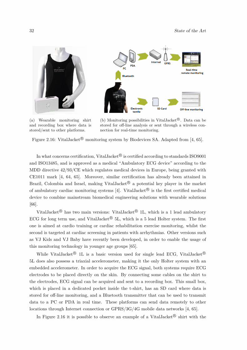
32 State of the Art
(a) Wearable monitoring shirtand recording box where data isstored/sent to other platforms.
(b) Monitoring possibilities in VitalJacketR©. Data can bestored for off-line analysis or sent through a wireless con-nection for real-time monitoring.
Figure 2.16: VitalJacket R© monitoring system by Biodevices SA. Adapted from [4, 65].
In what concerns certification, VitalJacket R© is certified according to standards ISO9001and ISO13485, and is approved as a medical “Ambulatory ECG device” according to theMDD directive 42/93/CE which regulates medical devices in Europe, being granted withCE1011 mark [4, 64, 65]. Moreover, similar certification has already been attained inBrazil, Colombia and Israel, making VitalJacket R© a potential key player in the marketof ambulatory cardiac monitoring systems [4]. VitalJacket R© is the first certified medicaldevice to combine mainstream biomedical engineering solutions with wearable solutions[66].
VitalJacket R© has two main versions: VitalJacket R© 1L, which is a 1 lead ambulatoryECG for long term use, and VitalJacket R© 5L, which is a 5 lead Holter system. The firstone is aimed at cardio training or cardiac rehabilitation exercise monitoring, whilst thesecond is targeted at cardiac screening in patients with arrhythmias. Other versions suchas VJ Kids and VJ Baby have recently been developed, in order to enable the usage ofthis monitoring technology in younger age groups [65].
While VitalJacket R© 1L is a basic version used for single lead ECG, VitalJacket R©
5L does also possess a triaxial accelerometer, making it the only Holter system with anembedded accelerometer. In order to acquire the ECG signal, both systems require ECGelectrodes to be placed directly on the skin. By connecting some cables on the shirt tothe electrodes, ECG signal can be acquired and sent to a recording box. This small box,which is placed in a dedicated pocket inside the t-shirt, has an SD card where data isstored for off-line monitoring, and a Bluetooth transmitter that can be used to transmitdata to a PC or PDA in real time. These platforms can send data remotely to otherlocations through Internet connection or GPRS/3G/4G mobile data networks [4, 65].
In Figure 2.16 it is possible to observe an example of a VitalJacket R© shirt with the
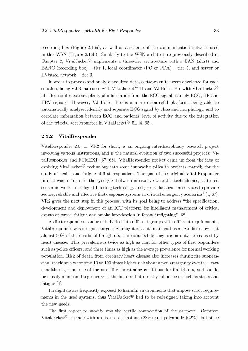
2.3 VitalResponder - pHealth for First Responders 33
recording box (Figure 2.16a), as well as a scheme of the communication network usedin this WSN (Figure 2.16b). Similarly to the WSN architecture previously described inChapter 2, VitalJacket R© implements a three-tier architecture with a BAN (shirt) andBANC (recording box) – tier 1, local coordinator (PC or PDA) – tier 2, and server orIP-based network – tier 3.
In order to process and analyse acquired data, software suites were developed for eachsolution, being VJ Rehab used with VitalJacket R© 1L and VJ Holter Pro with VitalJacket R©
5L. Both suites extract plenty of information from the ECG signal, namely ECG, HR andHRV signals. However, VJ Holter Pro is a more resourceful platform, being able toautomatically analyse, identify and separate ECG signal by class and morphology, and tocorrelate information between ECG and patients’ level of activity due to the integrationof the triaxial accelerometer in VitalJacket R© 5L [4, 65].
2.3.2 VitalResponder
VitalResponder 2.0, or VR2 for short, is an ongoing interdisciplinary research projectinvolving various institutions, and is the natural evolution of two successful projects: Vi-talResponder and FUMEXP [67, 68]. VitalResponder project came up from the idea ofevolving VitalJacket R© technology into some innovative pHealth projects, namely for thestudy of health and fatigue of first responders. The goal of the original Vital Responderproject was to “explore the synergies between innovative wearable technologies, scatteredsensor networks, intelligent building technology and precise localization services to providesecure, reliable and effective first-response systems in critical emergency scenarios” [4, 67].VR2 gives the next step in this process, with its goal being to address “the specification,development and deployment of an ICT platform for intelligent management of criticalevents of stress, fatigue and smoke intoxication in forest firefighting” [68].
As first responders can be subdivided into different groups with different requirements,VitalResponder was designed targeting firefighters as its main end-user. Studies show thatalmost 50% of the deaths of firefighters that occur while they are on duty, are caused byheart disease. This prevalence is twice as high as that for other types of first responderssuch as police officers, and three times as high as the average prevalence for normal workingpopulation. Risk of death from coronary heart disease also increases during fire suppres-sion, reaching a whopping 10 to 100 times higher risk than in non emergency events. Heartcondition is, thus, one of the most life threatening conditions for firefighters, and shouldbe closely monitored together with the factors that directly influence it, such as stress andfatigue [4].
Firefighters are frequently exposed to harmful environments that impose strict require-ments in the used systems, thus VitalJacket R© had to be redesigned taking into accountthe new needs.
The first aspect to modify was the textile composition of the garment. CommonVitalJacket R© is made with a mixture of elastane (28%) and polyamide (62%), but since
34 State of the Art
(a) Adapted VitalJacketR© shirt. (b) Enhanced helmet, with a microelectronicmodule for the detection of CO level, tem-perature and barometric pressure, circled inwhite.
Figure 2.17: Evolution of VitalJacket R© into the VitalResponder monitoring system. Re-trieved from [4].
elastane is heat sensitive and can burn wearer’s skin, textile composition had to be changedto follow international regulations on firefighters’ garments. Textile composition waschanged to a mixture of cotton (98%) and elastane (2%), with the external part of theshirt having only cotton. As the outer part heats more than the inner part of the shirt,having an elastane free composition in the outer part makes the shirt more protective andheat proof [4].
As electronics are embedded in the shirt and the shirt had its composition completelymodified, it was also necessary to redesign the way micro-cabling and micro-electroniccomponents were embedded in the shirt. Furthermore, since monitoring systems aimedat firefighters must monitor not only physiological signals but also acquire data from thesurrounding environment, a microelectronic module that measures CO level, temperatureand barometric pressure was inserted in firefighters’ helmets [4]. The resulting monitoringsystem can be seen in Figure 2.17.
Parallel to the physiological and environmental data acquiring system previously de-
2.3 VitalResponder - pHealth for First Responders 35
scribed, a wireless network based system was developed to monitor teams of first respon-ders. This system clusters acquired data, including individual vital signs (e.g. ECG)and position (localization through GPS), and provides it to the team coordinator. Thissystem does also have the ability to trigger alarms to the coordinator, supporting him incritical decision making by increasing his tactical awareness [4]. This system implementsa three-tier WSN architecture. In tier 1, there is the vital signs collecting unit using theVitalJacket R©. In tier 2, a Android smartphone (called DroidJacket) receives data fromtier 1 and processes it, whilst also measuring data with its GPS, accelerometer and gy-roscope sensors. DroidJacket is a key piece of the system as its data processing detectstechnical issues (e.g. loss of connectivity) and critical events in EGG (e.g. arrhythmias) orin activity patterns (e.g. fall or low activity patterns). Finally, data is sent to the mobilebase station in tier 3 through Wi-Fi connection, where the team coordinator can controllocation and health status of each individual using the VitalJacket R© and DroidJacketsystem [4].
Data acquired with VitalResponder systems is currently under study in order to analysestress of firefighters while in action. These studies focus on detecting stress indicators thatcan be used for stress and fatigue management. This is of critical importance, as powerfulmethodologies remain yet to be defined for long term monitoring of first responders’ stressand fatigue levels [4].

Chapter 3
VitalSensors - Towards a moreintelligent, wearable monitoringsystem
This thesis aims to improve a wearable monitoring system’s scalability, by working atfirmware and software levels in order to make it more capable and intelligent. This workis inserted in the framework of different projects, namely VitalLogger (VL) and VitalRe-sponder2.
3.1 Background
VitalLogger is a wearable monitoring device that seeks to expand VitalJacket R©’s exist-ing sensing capabilities. This device is directly connected to VitalJacket R©’s main board,and it possesses sensors that enable the measurement of novel physiological signals andenvironmental parameters. VitalResponder2 is also an evolution of the VitalJacket R© sys-tem, but that is specifically targeted at first responders. Among the various modulesthat VitalResponder2 has (adapted VitalJacket, helmet unit, etc), the system has variousimplemented sensors, namely sensors for various environmental parameters (gas sensors,positioning sensors, etc).
As referred previously in Chapter 1, work developed in this thesis is part of a greaterproject, where contributions from two other MSc students addressed specific areas of theproject. A more extensive component diagram showing the framework that comprises thisthesis’ work is showed in Figure 3.1. The aim of this greater project is to aggregate datafrom diverse vital signs and environmental parameters, and while it is mostly based onVitalLogger and VitalResponder2, it also includes VitalX.
VitalX, which has its logo presented on the left part of the diagram, is an Androidaggregator that receives, saves and displays information coming from connected devices.VitalX provides the user with the ability to easily control which sensors he wants to
37
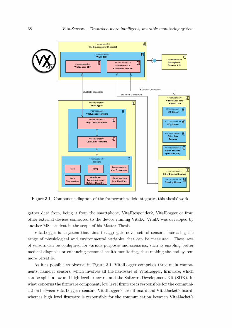
38 VitalSensors - Towards a more intelligent, wearable monitoring system
Figure 3.1: Component diagram of the framework which integrates this thesis’ work.
gather data from, being it from the smartphone, VitalResponder2, VitalLogger or fromother external devices connected to the device running VitalX. VitalX was developed byanother MSc student in the scope of his Master Thesis.
VitalLogger is a system that aims to aggregate novel sets of sensors, increasing therange of physiological and environmental variables that can be measured. These setsof sensors can be configured for various purposes and scenarios, such as enabling bettermedical diagnosis or enhancing personal health monitoring, thus making the end systemmore versatile.
As it is possible to observe in Figure 3.1, VitalLogger comprises three main compo-nents, namely: sensors, which involves all the hardware of VitalLogger; firmware, whichcan be split in low and high level firmware; and the Software Development Kit (SDK). Inwhat concerns the firmware component, low level firmware is responsible for the communi-cation between VitalLogger’s sensors, VitalLogger’s circuit board and VitalJacket’s board,whereas high level firmware is responsible for the communication between VitalJacket’s
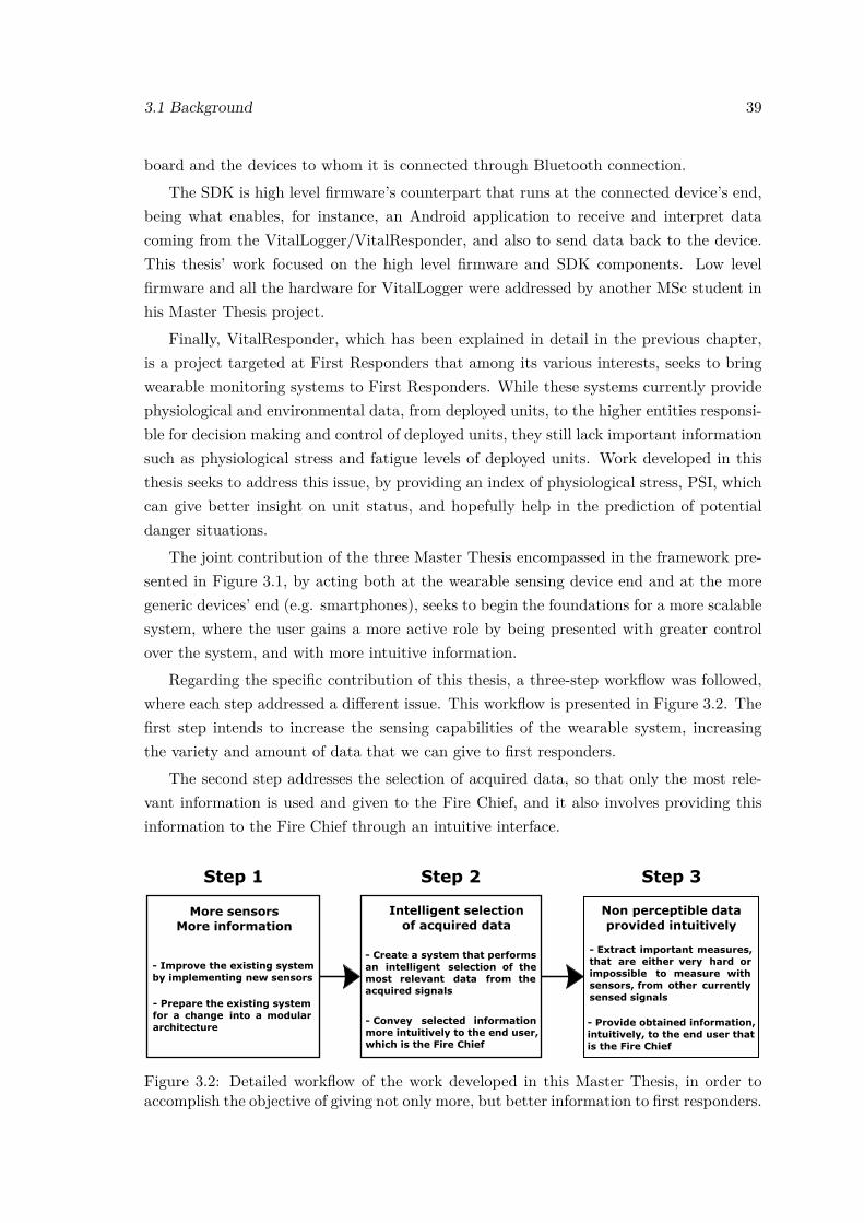
3.1 Background 39
board and the devices to whom it is connected through Bluetooth connection.The SDK is high level firmware’s counterpart that runs at the connected device’s end,
being what enables, for instance, an Android application to receive and interpret datacoming from the VitalLogger/VitalResponder, and also to send data back to the device.This thesis’ work focused on the high level firmware and SDK components. Low levelfirmware and all the hardware for VitalLogger were addressed by another MSc student inhis Master Thesis project.
Finally, VitalResponder, which has been explained in detail in the previous chapter,is a project targeted at First Responders that among its various interests, seeks to bringwearable monitoring systems to First Responders. While these systems currently providephysiological and environmental data, from deployed units, to the higher entities responsi-ble for decision making and control of deployed units, they still lack important informationsuch as physiological stress and fatigue levels of deployed units. Work developed in thisthesis seeks to address this issue, by providing an index of physiological stress, PSI, whichcan give better insight on unit status, and hopefully help in the prediction of potentialdanger situations.
The joint contribution of the three Master Thesis encompassed in the framework pre-sented in Figure 3.1, by acting both at the wearable sensing device end and at the moregeneric devices’ end (e.g. smartphones), seeks to begin the foundations for a more scalablesystem, where the user gains a more active role by being presented with greater controlover the system, and with more intuitive information.
Regarding the specific contribution of this thesis, a three-step workflow was followed,where each step addressed a different issue. This workflow is presented in Figure 3.2. Thefirst step intends to increase the sensing capabilities of the wearable system, increasingthe variety and amount of data that we can give to first responders.
The second step addresses the selection of acquired data, so that only the most rele-vant information is used and given to the Fire Chief, and it also involves providing thisinformation to the Fire Chief through an intuitive interface.
Step 1 Step 2 Step 3
- Improve the existing systemby implementing new sensors
- Provide obtained information,intuitively, to the end user thatis the Fire Chief
Non perceptible dataprovided intuitively
Intelligent selectionof acquired data
More sensorsMore information
Figure 3.2: Detailed workflow of the work developed in this Master Thesis, in order toaccomplish the objective of giving not only more, but better information to first responders.
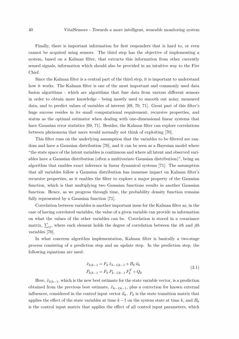
40 VitalSensors - Towards a more intelligent, wearable monitoring system
Finally, there is important information for first responders that is hard to, or evencannot be acquired using sensors. The third step has the objective of implementing asystem, based on a Kalman filter, that extracts this information from other currentlysensed signals, information which should also be provided in an intuitive way to the FireChief.
Since the Kalman filter is a central part of the third step, it is important to understandhow it works. The Kalman filter is one of the most important and commonly used datafusion algorithms - which are algorithms that fuse data from various different sensorsin order to obtain more knowledge - being mostly used to smooth out noisy, measureddata, and to predict values of variables of interest [69, 70, 71]. Great part of this filter’shuge success resides in its small computational requirement, recursive properties, andstatus as the optimal estimator when dealing with one-dimensional linear systems thathave Gaussian error statistics [69, 71]. Besides, the Kalman filter can explore correlationsbetween phenomena that users would normally not think of exploiting [70].
This filter runs on the underlying assumption that the variables to be filtered are ran-dom and have a Gaussian distribution [70], and it can be seen as a Bayesian model where“the state space of the latent variables is continuous and where all latent and observed vari-ables have a Gaussian distribution (often a multivariate Gaussian distribution)”, being analgorithm that enables exact inference in linear dynamical systems [71]. The assumptionthat all variables follow a Gaussian distribution has immense impact on Kalman filter’srecursive properties, as it enables the filter to explore a major property of the Gaussianfunction, which is that multiplying two Gaussian functions results in another Gaussianfunction. Hence, as we progress through time, the probability density function remainsfully represented by a Gaussian function [71].
Correlation between variables is another important issue for the Kalman filter as, in thecase of having correlated variables, the value of a given variable can provide us informationon what the values of the other variables can be. Correlation is stored in a covariancematrix,
∑ij , where each element holds the degree of correlation between the ith and jth
variables [70].In what concerns algorithm implementation, Kalman filter is basically a two-stage
process consisting of a prediction step and an update step. In the prediction step, thefollowing equations are used:
xk|k−1 = Fk xk−1|k−1 +Bk ~uk
Pk|k−1 = Fk Pk−1|k−1 F Tk +Qk
(3.1)
Here, xk|k−1, which is the new best estimate for the state variable vector, is a predictionobtained from the previous best estimate, xk−1|k−1, plus a correction for known externalinfluences, considered in the control input vector ~uk. Fk is the state transition matrix thatapplies the effect of the state variables at time k −1 on the system state at time k, and Bk
is the control input matrix that applies the effect of all control input parameters, which
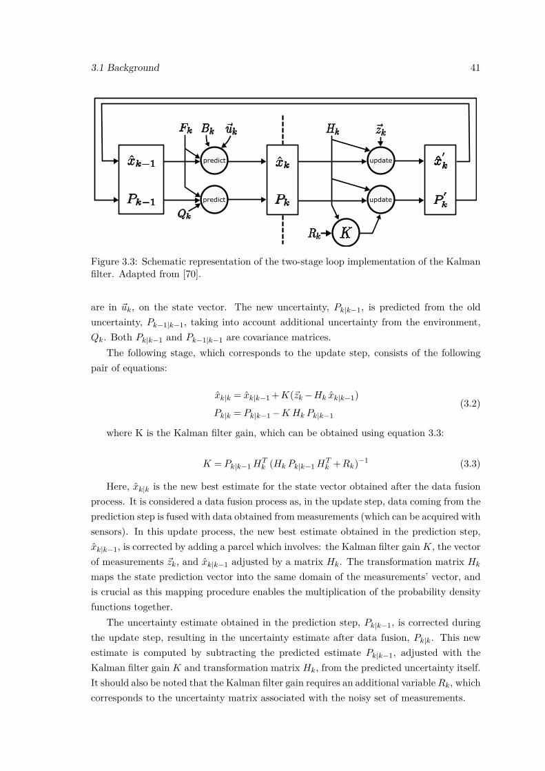
3.1 Background 41
predict
predict
update
update
Figure 3.3: Schematic representation of the two-stage loop implementation of the Kalmanfilter. Adapted from [70].
are in ~uk, on the state vector. The new uncertainty, Pk|k−1, is predicted from the olduncertainty, Pk−1|k−1, taking into account additional uncertainty from the environment,Qk. Both Pk|k−1 and Pk−1|k−1 are covariance matrices.
The following stage, which corresponds to the update step, consists of the followingpair of equations:
xk|k = xk|k−1 +K(~zk −Hk xk|k−1)
Pk|k = Pk|k−1 −K Hk Pk|k−1(3.2)
where K is the Kalman filter gain, which can be obtained using equation 3.3:
K = Pk|k−1 HTk (Hk Pk|k−1 HT
k +Rk)−1 (3.3)
Here, xk|k is the new best estimate for the state vector obtained after the data fusionprocess. It is considered a data fusion process as, in the update step, data coming from theprediction step is fused with data obtained from measurements (which can be acquired withsensors). In this update process, the new best estimate obtained in the prediction step,xk|k−1, is corrected by adding a parcel which involves: the Kalman filter gain K, the vectorof measurements ~zk, and xk|k−1 adjusted by a matrix Hk. The transformation matrix Hk
maps the state prediction vector into the same domain of the measurements’ vector, andis crucial as this mapping procedure enables the multiplication of the probability densityfunctions together.
The uncertainty estimate obtained in the prediction step, Pk|k−1, is corrected duringthe update step, resulting in the uncertainty estimate after data fusion, Pk|k. This newestimate is computed by subtracting the predicted estimate Pk|k−1, adjusted with theKalman filter gain K and transformation matrix Hk, from the predicted uncertainty itself.It should also be noted that the Kalman filter gain requires an additional variable Rk, whichcorresponds to the uncertainty matrix associated with the noisy set of measurements.

42 VitalSensors - Towards a more intelligent, wearable monitoring system
Figure 3.3 wraps up the iterative process in which the Kalman filter works. For thesake of simplicity, variables xk−1|k−1, Pk−1|k−1, xk|k−1, Pk|k−1, xk|k and Pk|k are displayedas xk−1, Pk−1, xk, Pk, x
′k and P
′k, respectively.
3.2 Methods
Before going through the explanation of the methods used to complete the proposed objec-tives, it is important to refer that the work herein described was developed in collaborationwith Biodevices SA, and that all implemented systems were developed having hardwarespecifications and restrictions in mind, as these can be a limiting factor.
3.2.1 Novel Sensing Capabilities
The first step of the workflow regarded adding more sensors to the system, and thusmaking the system capable of gathering more information for first responders.
In order to address this issue, the first part of the work consisted in introducing newsensors, in the VitalLogger device, which extend VitalJacket R©’s physiological and environ-mental sensing capabilities. Figure 3.4 shows a schematic representation of the migrationfrom the old VitalJacket system, to the new VitalLogger one, where three new sensorswere implemented.
Since this work was developed in collaboration with Biodevices SA, the choice of thenew sensors to be integrated in the system was ultimately decided by Biodevices SA. Thefollowing set of sensors was selected to be integrated in VitalLogger: SpO2 sensor, ambienttemperature sensor and humidity sensor.
3.2.1.1 Firmware Development for VitalLogger
With the group of sensors defined, work began on VitalLogger’s side, by dealing withthe high level firmware component. Firmware development and implementation was doneusing C programming language, and using the following software: MPLAB R© X IDE v3.00with the necessary MPLAB R© XC compiler (free edition) for the used microcontroller,MPLAB IPE v3.00 and PComm Terminal Emulator. MPLAB R© X IDE was used to codeand compile the .hex file (this is the firmware file) to run on the microchip. The circuitboard was connected to the computer through a MPLAB ICD 3 In-Circuit Debugger, andMPLAB R© X IPE was used to flash the .hex file into the microchip. Pcomm TerminalEmulator was used to connect the computer to VL’s circuit board through Bluetoothconnection, enabling the debugging of the coded firmware. An extension for MPLAB R© XIDE v3.00, named MPLAB R© Code Configurator, was also installed to facilitate control ofthe microcontroller’s pins.
It was decided, in conjunction with Biodevices SA, to implement VL’s firmware throughthe extension of VitalJacket’s firmware, thus new firmware was coded directly on Vital-
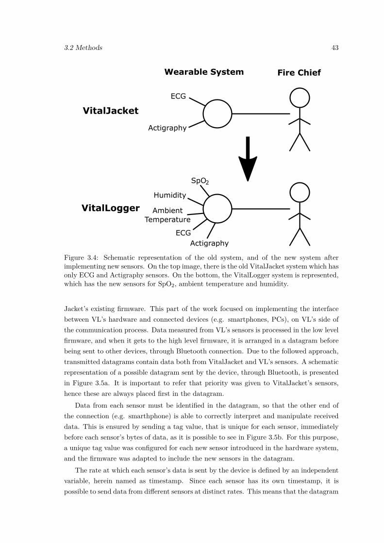
3.2 Methods 43
VitalJacket
VitalLogger
Figure 3.4: Schematic representation of the old system, and of the new system afterimplementing new sensors. On the top image, there is the old VitalJacket system which hasonly ECG and Actigraphy sensors. On the bottom, the VitalLogger system is represented,which has the new sensors for SpO2, ambient temperature and humidity.
Jacket’s existing firmware. This part of the work focused on implementing the interfacebetween VL’s hardware and connected devices (e.g. smartphones, PCs), on VL’s side ofthe communication process. Data measured from VL’s sensors is processed in the low levelfirmware, and when it gets to the high level firmware, it is arranged in a datagram beforebeing sent to other devices, through Bluetooth connection. Due to the followed approach,transmitted datagrams contain data both from VitalJacket and VL’s sensors. A schematicrepresentation of a possible datagram sent by the device, through Bluetooth, is presentedin Figure 3.5a. It is important to refer that priority was given to VitalJacket’s sensors,hence these are always placed first in the datagram.
Data from each sensor must be identified in the datagram, so that the other end ofthe connection (e.g. smarthphone) is able to correctly interpret and manipulate receiveddata. This is ensured by sending a tag value, that is unique for each sensor, immediatelybefore each sensor’s bytes of data, as it is possible to see in Figure 3.5b. For this purpose,a unique tag value was configured for each new sensor introduced in the hardware system,and the firmware was adapted to include the new sensors in the datagram.
The rate at which each sensor’s data is sent by the device is defined by an independentvariable, herein named as timestamp. Since each sensor has its own timestamp, it ispossible to send data from different sensors at distinct rates. This means that the datagram
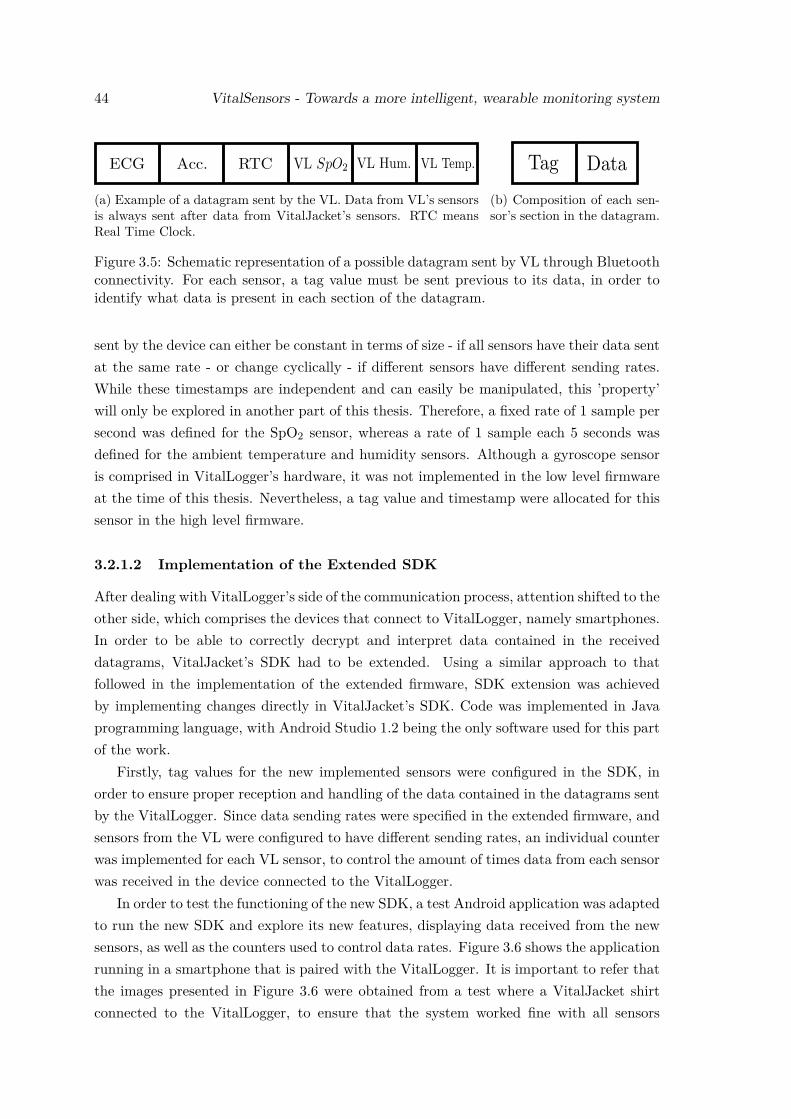
44 VitalSensors - Towards a more intelligent, wearable monitoring system
(a) Example of a datagram sent by the VL. Data from VL’s sensorsis always sent after data from VitalJacket’s sensors. RTC meansReal Time Clock.
(b) Composition of each sen-sor’s section in the datagram.
Figure 3.5: Schematic representation of a possible datagram sent by VL through Bluetoothconnectivity. For each sensor, a tag value must be sent previous to its data, in order toidentify what data is present in each section of the datagram.
sent by the device can either be constant in terms of size - if all sensors have their data sentat the same rate - or change cyclically - if different sensors have different sending rates.While these timestamps are independent and can easily be manipulated, this ’property’will only be explored in another part of this thesis. Therefore, a fixed rate of 1 sample persecond was defined for the SpO2 sensor, whereas a rate of 1 sample each 5 seconds wasdefined for the ambient temperature and humidity sensors. Although a gyroscope sensoris comprised in VitalLogger’s hardware, it was not implemented in the low level firmwareat the time of this thesis. Nevertheless, a tag value and timestamp were allocated for thissensor in the high level firmware.
3.2.1.2 Implementation of the Extended SDK
After dealing with VitalLogger’s side of the communication process, attention shifted to theother side, which comprises the devices that connect to VitalLogger, namely smartphones.In order to be able to correctly decrypt and interpret data contained in the receiveddatagrams, VitalJacket’s SDK had to be extended. Using a similar approach to thatfollowed in the implementation of the extended firmware, SDK extension was achievedby implementing changes directly in VitalJacket’s SDK. Code was implemented in Javaprogramming language, with Android Studio 1.2 being the only software used for this partof the work.
Firstly, tag values for the new implemented sensors were configured in the SDK, inorder to ensure proper reception and handling of the data contained in the datagrams sentby the VitalLogger. Since data sending rates were specified in the extended firmware, andsensors from the VL were configured to have different sending rates, an individual counterwas implemented for each VL sensor, to control the amount of times data from each sensorwas received in the device connected to the VitalLogger.
In order to test the functioning of the new SDK, a test Android application was adaptedto run the new SDK and explore its new features, displaying data received from the newsensors, as well as the counters used to control data rates. Figure 3.6 shows the applicationrunning in a smartphone that is paired with the VitalLogger. It is important to refer thatthe images presented in Figure 3.6 were obtained from a test where a VitalJacket shirtconnected to the VitalLogger, to ensure that the system worked fine with all sensors
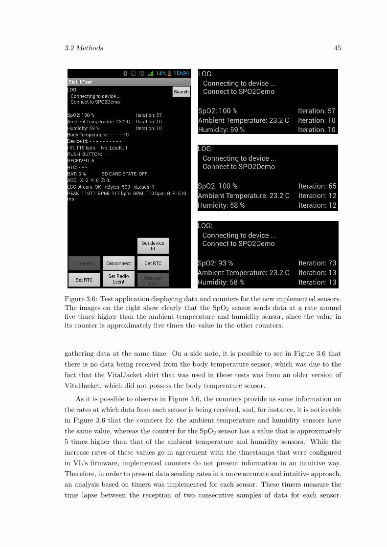
3.2 Methods 45
Figure 3.6: Test application displaying data and counters for the new implemented sensors.The images on the right show clearly that the SpO2 sensor sends data at a rate aroundfive times higher than the ambient temperature and humidity sensor, since the value inits counter is approximately five times the value in the other counters.
gathering data at the same time. On a side note, it is possible to see in Figure 3.6 thatthere is no data being received from the body temperature sensor, which was due to thefact that the VitalJacket shirt that was used in these tests was from an older version ofVitalJacket, which did not possess the body temperature sensor.
As it is possible to observe in Figure 3.6, the counters provide us some information onthe rates at which data from each sensor is being received, and, for instance, it is noticeablein Figure 3.6 that the counters for the ambient temperature and humidity sensors havethe same value, whereas the counter for the SpO2 sensor has a value that is approximately5 times higher than that of the ambient temperature and humidity sensors. While theincrease rates of these values go in agreement with the timestamps that were configuredin VL’s firmware, implemented counters do not present information in an intuitive way.Therefore, in order to present data sending rates in a more accurate and intuitive approach,an analysis based on timers was implemented for each sensor. These timers measure thetime lapse between the reception of two consecutive samples of data for each sensor.
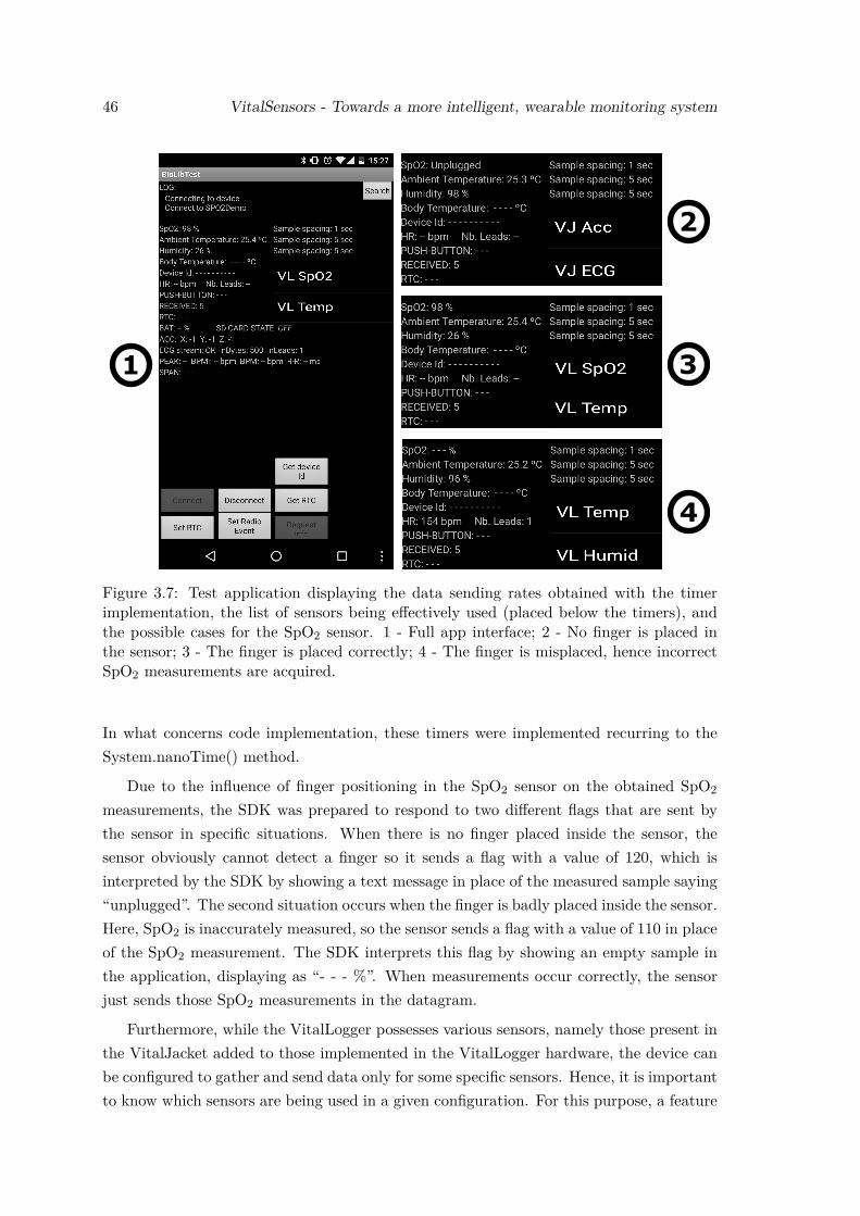
46 VitalSensors - Towards a more intelligent, wearable monitoring system
1
2
3
4
Figure 3.7: Test application displaying the data sending rates obtained with the timerimplementation, the list of sensors being effectively used (placed below the timers), andthe possible cases for the SpO2 sensor. 1 - Full app interface; 2 - No finger is placed inthe sensor; 3 - The finger is placed correctly; 4 - The finger is misplaced, hence incorrectSpO2 measurements are acquired.
In what concerns code implementation, these timers were implemented recurring to theSystem.nanoTime() method.
Due to the influence of finger positioning in the SpO2 sensor on the obtained SpO2
measurements, the SDK was prepared to respond to two different flags that are sent bythe sensor in specific situations. When there is no finger placed inside the sensor, thesensor obviously cannot detect a finger so it sends a flag with a value of 120, which isinterpreted by the SDK by showing a text message in place of the measured sample saying“unplugged”. The second situation occurs when the finger is badly placed inside the sensor.Here, SpO2 is inaccurately measured, so the sensor sends a flag with a value of 110 in placeof the SpO2 measurement. The SDK interprets this flag by showing an empty sample inthe application, displaying as “- - - %”. When measurements occur correctly, the sensorjust sends those SpO2 measurements in the datagram.
Furthermore, while the VitalLogger possesses various sensors, namely those present inthe VitalJacket added to those implemented in the VitalLogger hardware, the device canbe configured to gather and send data only for some specific sensors. Hence, it is importantto know which sensors are being used in a given configuration. For this purpose, a feature
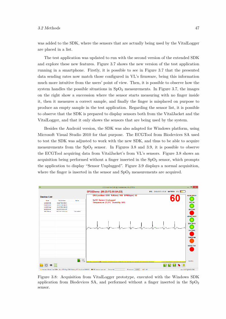
3.2 Methods 47
was added to the SDK, where the sensors that are actually being used by the VitalLoggerare placed in a list.
The test application was updated to run with the second version of the extended SDKand explore these new features. Figure 3.7 shows the new version of the test applicationrunning in a smartphone. Firstly, it is possible to see in Figure 3.7 that the presenteddata sending rates now match those configured in VL’s firmware, being this informationmuch more intuitive from the users’ point of view. Then, it is possible to observe how thesystem handles the possible situations in SpO2 measurements. In Figure 3.7, the imageson the right show a succession where the sensor starts measuring with no finger insideit, then it measures a correct sample, and finally the finger is misplaced on purpose toproduce an empty sample in the test application. Regarding the sensor list, it is possibleto observe that the SDK is prepared to display sensors both from the VitalJacket and theVitalLogger, and that it only shows the sensors that are being used by the system.
Besides the Android version, the SDK was also adapted for Windows platform, usingMicrosoft Visual Studio 2010 for that purpose. The ECGTool from Biodevices SA usedto test the SDK was adjusted to work with the new SDK, and thus to be able to acquiremeasurements from the SpO2 sensor. In Figures 3.8 and 3.9, it is possible to observethe ECGTool acquiring data from VitalJacket’s from VL’s sensors. Figure 3.8 shows anacquisition being performed without a finger inserted in the SpO2 sensor, which promptsthe application to display “Sensor Unplugged”. Figure 3.9 displays a normal acquisition,where the finger is inserted in the sensor and SpO2 measurements are acquired.
Figure 3.8: Acquisition from VitalLogger prototype, executed with the Windows SDKapplication from Biodevices SA, and performed without a finger inserted in the SpO2sensor.
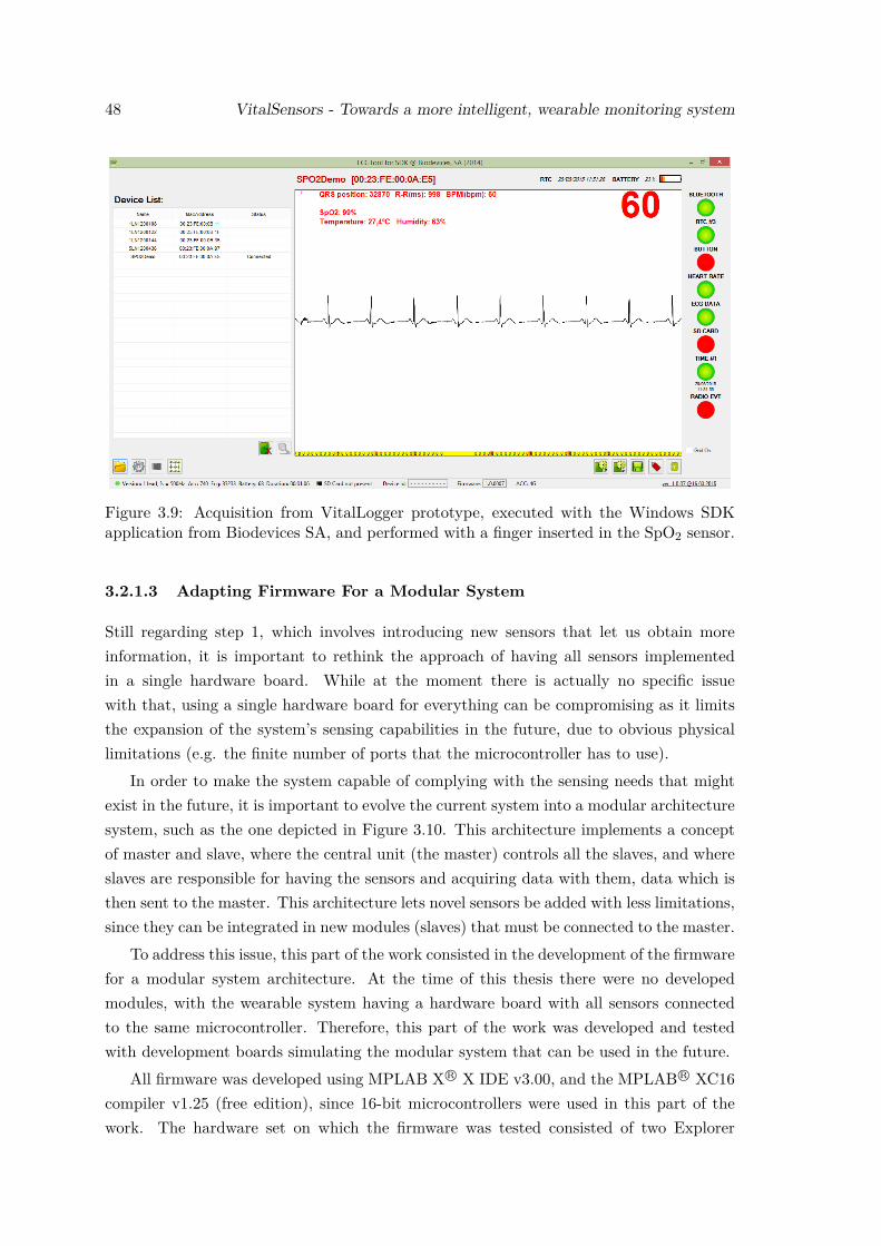
48 VitalSensors - Towards a more intelligent, wearable monitoring system
Figure 3.9: Acquisition from VitalLogger prototype, executed with the Windows SDKapplication from Biodevices SA, and performed with a finger inserted in the SpO2 sensor.
3.2.1.3 Adapting Firmware For a Modular System
Still regarding step 1, which involves introducing new sensors that let us obtain moreinformation, it is important to rethink the approach of having all sensors implementedin a single hardware board. While at the moment there is actually no specific issuewith that, using a single hardware board for everything can be compromising as it limitsthe expansion of the system’s sensing capabilities in the future, due to obvious physicallimitations (e.g. the finite number of ports that the microcontroller has to use).
In order to make the system capable of complying with the sensing needs that mightexist in the future, it is important to evolve the current system into a modular architecturesystem, such as the one depicted in Figure 3.10. This architecture implements a conceptof master and slave, where the central unit (the master) controls all the slaves, and whereslaves are responsible for having the sensors and acquiring data with them, data which isthen sent to the master. This architecture lets novel sensors be added with less limitations,since they can be integrated in new modules (slaves) that must be connected to the master.
To address this issue, this part of the work consisted in the development of the firmwarefor a modular system architecture. At the time of this thesis there were no developedmodules, with the wearable system having a hardware board with all sensors connectedto the same microcontroller. Therefore, this part of the work was developed and testedwith development boards simulating the modular system that can be used in the future.
All firmware was developed using MPLAB X R© X IDE v3.00, and the MPLAB R© XC16compiler v1.25 (free edition), since 16-bit microcontrollers were used in this part of thework. The hardware set on which the firmware was tested consisted of two Explorer
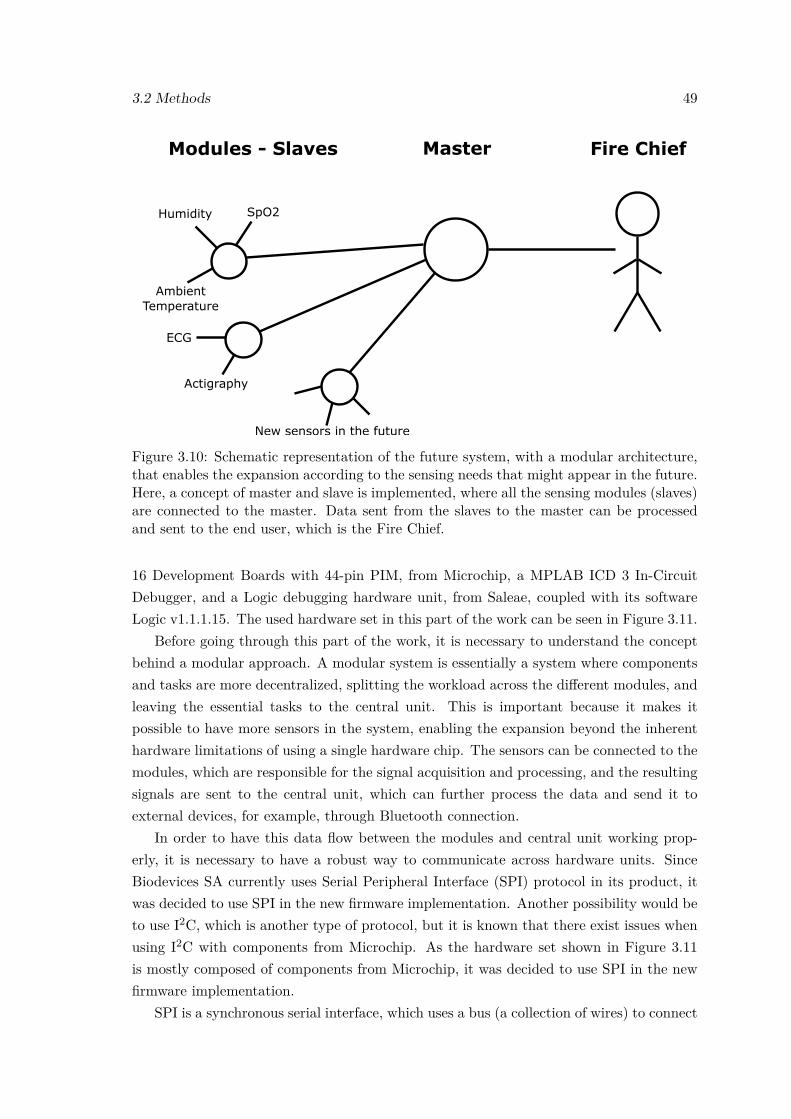
3.2 Methods 49
ECG
Actigraphy
New sensors in the future
Figure 3.10: Schematic representation of the future system, with a modular architecture,that enables the expansion according to the sensing needs that might appear in the future.Here, a concept of master and slave is implemented, where all the sensing modules (slaves)are connected to the master. Data sent from the slaves to the master can be processedand sent to the end user, which is the Fire Chief.
16 Development Boards with 44-pin PIM, from Microchip, a MPLAB ICD 3 In-CircuitDebugger, and a Logic debugging hardware unit, from Saleae, coupled with its softwareLogic v1.1.1.15. The used hardware set in this part of the work can be seen in Figure 3.11.
Before going through this part of the work, it is necessary to understand the conceptbehind a modular approach. A modular system is essentially a system where componentsand tasks are more decentralized, splitting the workload across the different modules, andleaving the essential tasks to the central unit. This is important because it makes itpossible to have more sensors in the system, enabling the expansion beyond the inherenthardware limitations of using a single hardware chip. The sensors can be connected to themodules, which are responsible for the signal acquisition and processing, and the resultingsignals are sent to the central unit, which can further process the data and send it toexternal devices, for example, through Bluetooth connection.
In order to have this data flow between the modules and central unit working prop-erly, it is necessary to have a robust way to communicate across hardware units. SinceBiodevices SA currently uses Serial Peripheral Interface (SPI) protocol in its product, itwas decided to use SPI in the new firmware implementation. Another possibility would beto use I2C, which is another type of protocol, but it is known that there exist issues whenusing I2C with components from Microchip. As the hardware set shown in Figure 3.11is mostly composed of components from Microchip, it was decided to use SPI in the newfirmware implementation.
SPI is a synchronous serial interface, which uses a bus (a collection of wires) to connect
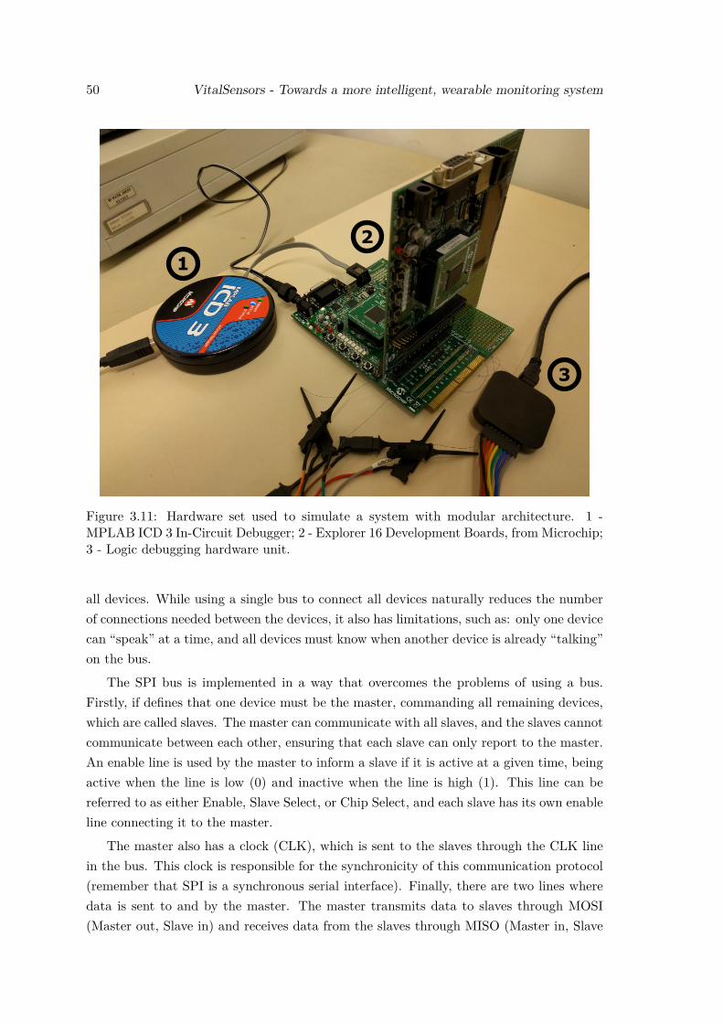
50 VitalSensors - Towards a more intelligent, wearable monitoring system
1
2
3
Figure 3.11: Hardware set used to simulate a system with modular architecture. 1 -MPLAB ICD 3 In-Circuit Debugger; 2 - Explorer 16 Development Boards, from Microchip;3 - Logic debugging hardware unit.
all devices. While using a single bus to connect all devices naturally reduces the numberof connections needed between the devices, it also has limitations, such as: only one devicecan “speak” at a time, and all devices must know when another device is already “talking”on the bus.
The SPI bus is implemented in a way that overcomes the problems of using a bus.Firstly, if defines that one device must be the master, commanding all remaining devices,which are called slaves. The master can communicate with all slaves, and the slaves cannotcommunicate between each other, ensuring that each slave can only report to the master.An enable line is used by the master to inform a slave if it is active at a given time, beingactive when the line is low (0) and inactive when the line is high (1). This line can bereferred to as either Enable, Slave Select, or Chip Select, and each slave has its own enableline connecting it to the master.
The master also has a clock (CLK), which is sent to the slaves through the CLK linein the bus. This clock is responsible for the synchronicity of this communication protocol(remember that SPI is a synchronous serial interface). Finally, there are two lines wheredata is sent to and by the master. The master transmits data to slaves through MOSI(Master out, Slave in) and receives data from the slaves through MISO (Master in, Slave
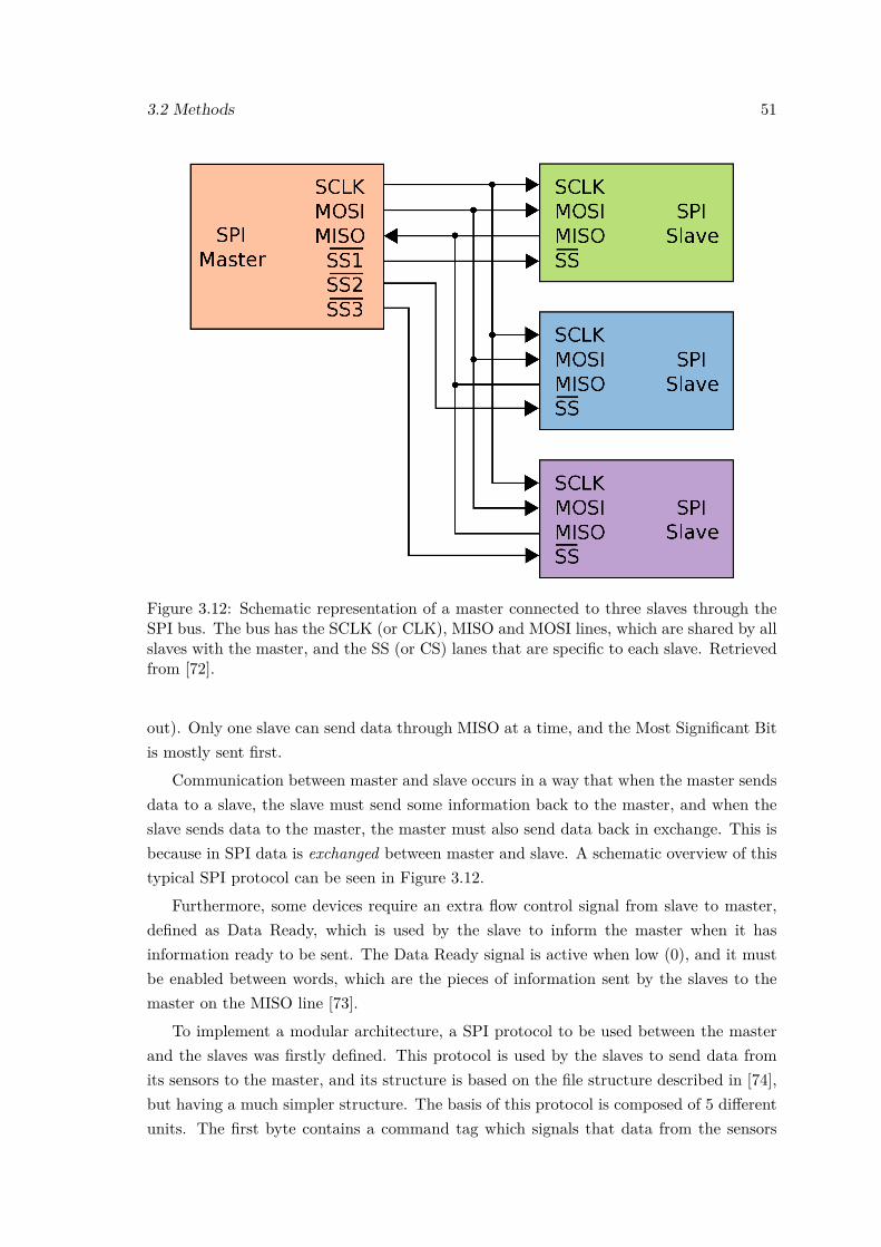
3.2 Methods 51
Figure 3.12: Schematic representation of a master connected to three slaves through theSPI bus. The bus has the SCLK (or CLK), MISO and MOSI lines, which are shared by allslaves with the master, and the SS (or CS) lanes that are specific to each slave. Retrievedfrom [72].
out). Only one slave can send data through MISO at a time, and the Most Significant Bitis mostly sent first.
Communication between master and slave occurs in a way that when the master sendsdata to a slave, the slave must send some information back to the master, and when theslave sends data to the master, the master must also send data back in exchange. This isbecause in SPI data is exchanged between master and slave. A schematic overview of thistypical SPI protocol can be seen in Figure 3.12.
Furthermore, some devices require an extra flow control signal from slave to master,defined as Data Ready, which is used by the slave to inform the master when it hasinformation ready to be sent. The Data Ready signal is active when low (0), and it mustbe enabled between words, which are the pieces of information sent by the slaves to themaster on the MISO line [73].
To implement a modular architecture, a SPI protocol to be used between the masterand the slaves was firstly defined. This protocol is used by the slaves to send data fromits sensors to the master, and its structure is based on the file structure described in [74],but having a much simpler structure. The basis of this protocol is composed of 5 differentunits. The first byte contains a command tag which signals that data from the sensors
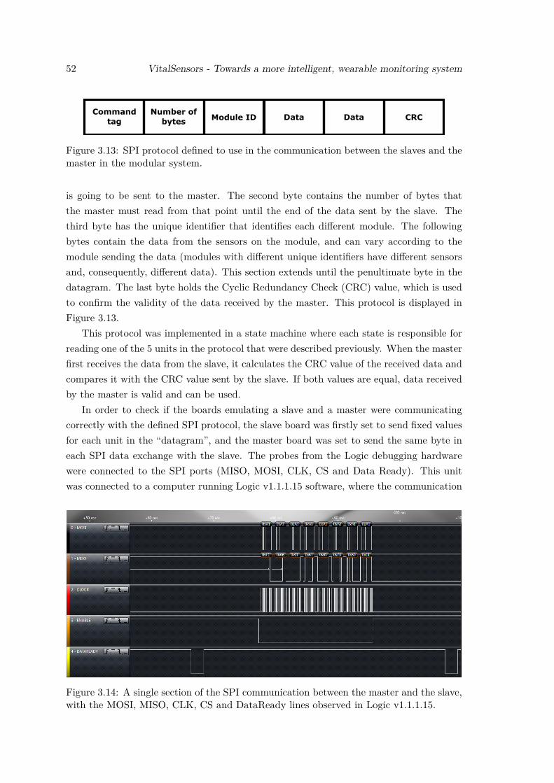
52 VitalSensors - Towards a more intelligent, wearable monitoring system
Commandtag
Number ofbytes Module ID Data Data CRC
Figure 3.13: SPI protocol defined to use in the communication between the slaves and themaster in the modular system.
is going to be sent to the master. The second byte contains the number of bytes thatthe master must read from that point until the end of the data sent by the slave. Thethird byte has the unique identifier that identifies each different module. The followingbytes contain the data from the sensors on the module, and can vary according to themodule sending the data (modules with different unique identifiers have different sensorsand, consequently, different data). This section extends until the penultimate byte in thedatagram. The last byte holds the Cyclic Redundancy Check (CRC) value, which is usedto confirm the validity of the data received by the master. This protocol is displayed inFigure 3.13.
This protocol was implemented in a state machine where each state is responsible forreading one of the 5 units in the protocol that were described previously. When the masterfirst receives the data from the slave, it calculates the CRC value of the received data andcompares it with the CRC value sent by the slave. If both values are equal, data receivedby the master is valid and can be used.
In order to check if the boards emulating a slave and a master were communicatingcorrectly with the defined SPI protocol, the slave board was firstly set to send fixed valuesfor each unit in the “datagram”, and the master board was set to send the same byte ineach SPI data exchange with the slave. The probes from the Logic debugging hardwarewere connected to the SPI ports (MISO, MOSI, CLK, CS and Data Ready). This unitwas connected to a computer running Logic v1.1.1.15 software, where the communication
Figure 3.14: A single section of the SPI communication between the master and the slave,with the MOSI, MISO, CLK, CS and DataReady lines observed in Logic v1.1.1.15.
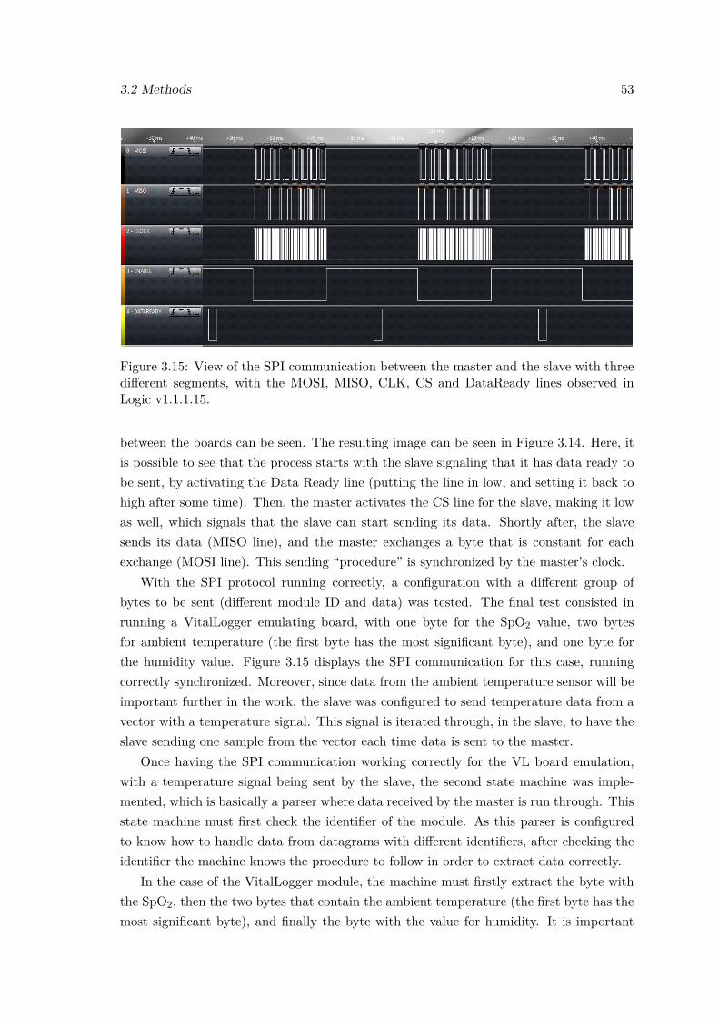
3.2 Methods 53
Figure 3.15: View of the SPI communication between the master and the slave with threedifferent segments, with the MOSI, MISO, CLK, CS and DataReady lines observed inLogic v1.1.1.15.
between the boards can be seen. The resulting image can be seen in Figure 3.14. Here, itis possible to see that the process starts with the slave signaling that it has data ready tobe sent, by activating the Data Ready line (putting the line in low, and setting it back tohigh after some time). Then, the master activates the CS line for the slave, making it lowas well, which signals that the slave can start sending its data. Shortly after, the slavesends its data (MISO line), and the master exchanges a byte that is constant for eachexchange (MOSI line). This sending “procedure” is synchronized by the master’s clock.
With the SPI protocol running correctly, a configuration with a different group ofbytes to be sent (different module ID and data) was tested. The final test consisted inrunning a VitalLogger emulating board, with one byte for the SpO2 value, two bytesfor ambient temperature (the first byte has the most significant byte), and one byte forthe humidity value. Figure 3.15 displays the SPI communication for this case, runningcorrectly synchronized. Moreover, since data from the ambient temperature sensor will beimportant further in the work, the slave was configured to send temperature data from avector with a temperature signal. This signal is iterated through, in the slave, to have theslave sending one sample from the vector each time data is sent to the master.
Once having the SPI communication working correctly for the VL board emulation,with a temperature signal being sent by the slave, the second state machine was imple-mented, which is basically a parser where data received by the master is run through. Thisstate machine must first check the identifier of the module. As this parser is configuredto know how to handle data from datagrams with different identifiers, after checking theidentifier the machine knows the procedure to follow in order to extract data correctly.
In the case of the VitalLogger module, the machine must firstly extract the byte withthe SpO2, then the two bytes that contain the ambient temperature (the first byte has themost significant byte), and finally the byte with the value for humidity. It is important

54 VitalSensors - Towards a more intelligent, wearable monitoring system
to refer once again that configurations for future modules must be implemented in thisstate machine, so that it knows how to properly handle data received from different slaves.After running the data through the parser, extracted data is ready for being used by themaster in other tasks.
3.2.2 Intelligent Data Reduction
With large amounts of data being gathered by the wearable system, for instance fromVitalLogger and VitalResponder, it is important to select the data that is given to theFire Chief, in order to reduce data redundancy and to make it easier for the users, namelythe First Responders who have to carefully control gathered data and analyze it to detectrisk situations. Moreover, this information should be conveyed intuitively, so that the FireChief can interpret it more easily and quickly.
To reduce the amount of data passed from the wearable system to the user, a controlsystem was developed to intelligently select the data to be sent to the interface that showsthe data to the user (for instance, an android application running on a smartphone), thusreducing data redundancy. The algorithm for this control system was projected and devel-oped so that it complies with data from the different sensors that are implemented. Then,it was decided to implement the system with a specific sensor. The ambient temperaturesensor was selected as it possesses important information for the First Responders, whofrequently operate on hazardous conditions.
Figure 3.16 is important to explain how this system works. This figure exemplifies,with an ambient temperature signal, two possible scenarios that the selecting system canbe presented with. In both signals ambient temperature starts within acceptable levels.Two thresholds are visible in the figure, but since this work is aimed at first responders,namely firefighters, only the higher one is relevant. When temperatures stay within this“safe region”, data is sent to the Fire Chief at a slower rate, as changes within this regionare less important for the Fire Chief to keep track of.
As temperature increases beyond the upper threshold, the system should notify the FireChief with more information, by providing him temperature measurements at a faster rate.When temperature rises above the upper threshold, two situations can occur. The first oneis shown by Signal 1 in Figure 3.16, where temperature rises sharply above the threshold.When temperature change is steep, the system should automatically select a faster ratefor sending temperature measurements to the Fire Chief. The second possible situationis depicted by Signal 2, where temperature rises above the threshold but far less sharply.Here, the system should adapt itself to send temperature measurements to the Fire Chiefat a faster rate than that used inside the “safe region”, yet slower when compared to therates used in the situation presented in Signal 1. When temperatures get back below theupper threshold, the system should automatically start sending temperatures at a slowerrate.
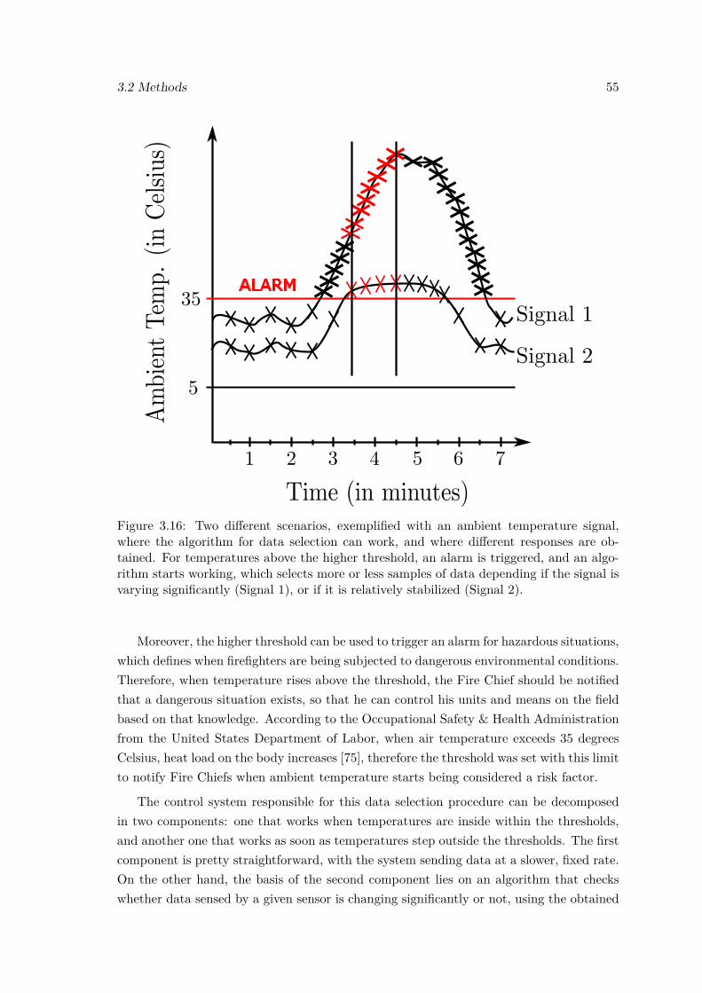
3.2 Methods 55
Figure 3.16: Two different scenarios, exemplified with an ambient temperature signal,where the algorithm for data selection can work, and where different responses are ob-tained. For temperatures above the higher threshold, an alarm is triggered, and an algo-rithm starts working, which selects more or less samples of data depending if the signal isvarying significantly (Signal 1), or if it is relatively stabilized (Signal 2).
Moreover, the higher threshold can be used to trigger an alarm for hazardous situations,which defines when firefighters are being subjected to dangerous environmental conditions.Therefore, when temperature rises above the threshold, the Fire Chief should be notifiedthat a dangerous situation exists, so that he can control his units and means on the fieldbased on that knowledge. According to the Occupational Safety & Health Administrationfrom the United States Department of Labor, when air temperature exceeds 35 degreesCelsius, heat load on the body increases [75], therefore the threshold was set with this limitto notify Fire Chiefs when ambient temperature starts being considered a risk factor.
The control system responsible for this data selection procedure can be decomposedin two components: one that works when temperatures are inside within the thresholds,and another one that works as soon as temperatures step outside the thresholds. The firstcomponent is pretty straightforward, with the system sending data at a slower, fixed rate.On the other hand, the basis of the second component lies on an algorithm that checkswhether data sensed by a given sensor is changing significantly or not, using the obtained
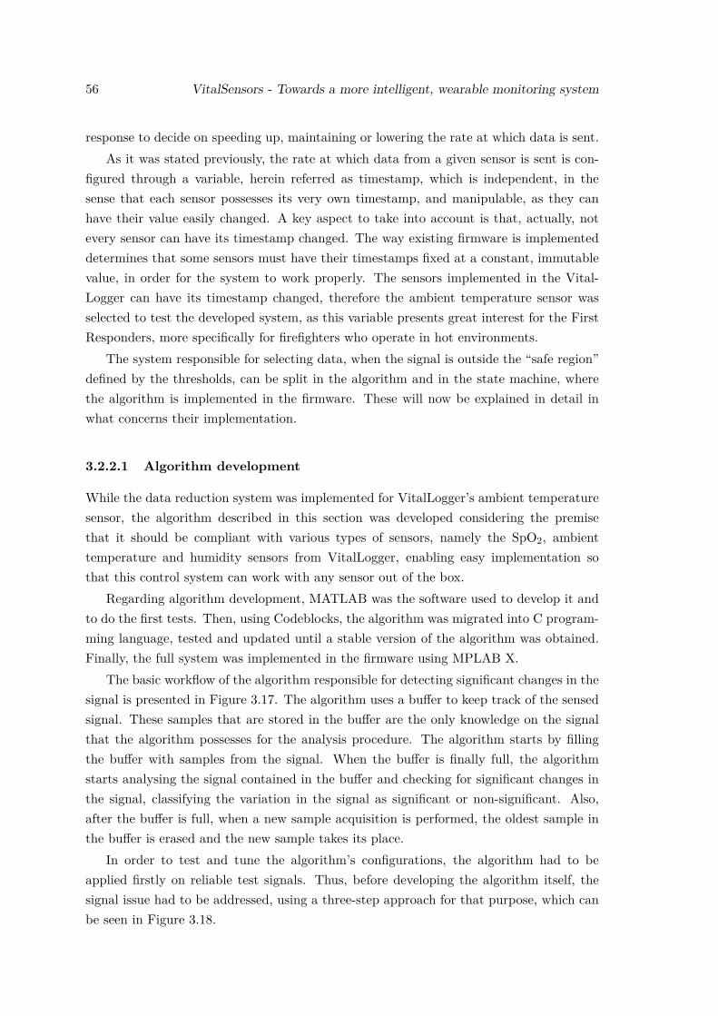
56 VitalSensors - Towards a more intelligent, wearable monitoring system
response to decide on speeding up, maintaining or lowering the rate at which data is sent.As it was stated previously, the rate at which data from a given sensor is sent is con-
figured through a variable, herein referred as timestamp, which is independent, in thesense that each sensor possesses its very own timestamp, and manipulable, as they canhave their value easily changed. A key aspect to take into account is that, actually, notevery sensor can have its timestamp changed. The way existing firmware is implementeddetermines that some sensors must have their timestamps fixed at a constant, immutablevalue, in order for the system to work properly. The sensors implemented in the Vital-Logger can have its timestamp changed, therefore the ambient temperature sensor wasselected to test the developed system, as this variable presents great interest for the FirstResponders, more specifically for firefighters who operate in hot environments.
The system responsible for selecting data, when the signal is outside the “safe region”defined by the thresholds, can be split in the algorithm and in the state machine, wherethe algorithm is implemented in the firmware. These will now be explained in detail inwhat concerns their implementation.
3.2.2.1 Algorithm development
While the data reduction system was implemented for VitalLogger’s ambient temperaturesensor, the algorithm described in this section was developed considering the premisethat it should be compliant with various types of sensors, namely the SpO2, ambienttemperature and humidity sensors from VitalLogger, enabling easy implementation sothat this control system can work with any sensor out of the box.
Regarding algorithm development, MATLAB was the software used to develop it andto do the first tests. Then, using Codeblocks, the algorithm was migrated into C program-ming language, tested and updated until a stable version of the algorithm was obtained.Finally, the full system was implemented in the firmware using MPLAB X.
The basic workflow of the algorithm responsible for detecting significant changes in thesignal is presented in Figure 3.17. The algorithm uses a buffer to keep track of the sensedsignal. These samples that are stored in the buffer are the only knowledge on the signalthat the algorithm possesses for the analysis procedure. The algorithm starts by fillingthe buffer with samples from the signal. When the buffer is finally full, the algorithmstarts analysing the signal contained in the buffer and checking for significant changes inthe signal, classifying the variation in the signal as significant or non-significant. Also,after the buffer is full, when a new sample acquisition is performed, the oldest sample inthe buffer is erased and the new sample takes its place.
In order to test and tune the algorithm’s configurations, the algorithm had to beapplied firstly on reliable test signals. Thus, before developing the algorithm itself, thesignal issue had to be addressed, using a three-step approach for that purpose, which canbe seen in Figure 3.18.
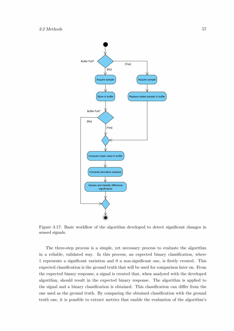
3.2 Methods 57
Figure 3.17: Basic workflow of the algorithm developed to detect significant changes insensed signals.
The three-step process is a simple, yet necessary process to evaluate the algorithmin a reliable, validated way. In this process, an expected binary classification, where1 represents a significant variation and 0 a non-significant one, is firstly created. Thisexpected classification is the ground truth that will be used for comparison later on. Fromthe expected binary response, a signal is created that, when analysed with the developedalgorithm, should result in the expected binary response. The algorithm is applied tothe signal and a binary classification is obtained. This classification can differ from theone used as the ground truth. By comparing the obtained classification with the groundtruth one, it is possible to extract metrics that enable the evaluation of the algorithm’s
58 VitalSensors - Towards a more intelligent, wearable monitoring system
A B C
Figure 3.18: Three-step process used to test and evaluate the algorithm with knownsignals. A - classification’s ground truth, B - original signal, C - classification obtainedwith the algorithm.
performance.To use this three-step process, a signal generator with different binary responses and
resulting signals was created. For each binary response, different possible signals werecreated, with each binary response representing a possible trend in the signal. The finalversion of the generator has 14 different signals, which were used to evaluate and tunethe algorithm. An example of a signal contained in the generator is the one presentedin Figure 3.18, where the binary classification on the left and the signal in the middleare both contained in the generator. This specific example represents a situation wherea sudden, significant change in a noisy signal occurs. Due to the presence of noise in thesignal, there is the possibility of detecting false significant changes in the signal.
With the signal generator fully functional, it was time to work on the algorithm itself.The development phase had to take into account the existing limitations at the hardwarelevel (e.g. free memory available to use), which directly affects some aspects such as usedbuffer size. Consequently, buffer size limits the maximum possible delay to use in thederivative analysis, which is buffer size minus 1, since 1 of the samples in the buffer holdsthe value for the current measurement.
The threshold selected for the classification of signal variation as significant or non-significant is based on the mean value of the signal contained in the buffer. This is in factan adaptative threshold since it works as a sliding mean which changes according to theknowledge on the signal we have from past samples present in the buffer. This thresholdcriteria enables the implementation of the algorithm for various types of signal, as thecriteria only depends on the measured signal. It should be noted that since this thresholddepends on the magnitude of the signal, some baseline bias might occur.
The effective threshold criteria used in the algorithm consists in a percentage of theabove mentioned mean value of the signal saved in the buffer, hence the higher the signal’smagnitude, the bigger the signal changes must be in order to be labeled as significant.
While developing and testing the algorithm, three different parameters were varied:buffer size, which directly affects the threshold and the maximum possible delay; sample
3.2 Methods 59
delay to use in the derivative analysis; and the percentage of the mean value of the signalin the buffer to use as threshold. In order to get a good understanding of the algorithm,these three parameters were varied as follows, keeping in mind the hardware restrictions:
• Buffer size: 5, 10 and 20 samples;
• Sample delay: varied from 1 to 19, in integer values;
• Percentage of the mean value: varied from 0.0001% to 10%.
Buffer size was kept small in order to comply with hardware issues such as availablememory. Delay was varied to the maximum value that the buffer size enables, which isbuffer size minus 1. Threshold was varied from very low to very high values to assess howthe algorithm behaves throughout the threshold span.
All variables are important in the system as each of them affects how the algorithmresponds to noise. For instance, higher buffer sizes and sample delays should increase signalsmoothing and noise filtering, whereas higher thresholds should result in the algorithmpicking up less noise, since noise is frequently associated with smaller, non-significantchanges, that are wrongly detected by the system. The optimal combination of thesethree variables is a crucial aspect to achieve a system that can perform well when giveneither clean or noisy signals.
The algorithm was firstly implemented in MATLAB, varying the parameters as previ-ously referred. Since signals generated by the developed signal simulator contained randomnoise, the algorithm was run for a high number of iterations (1500), for each combinationof the three parameters, in order to reduce the influence of the random nature of noise inthe results obtained for the different parameter sets.
To evaluate the performance of the algorithm, accuracy, precision, sensitivity, speci-ficity and F1 score were computed using equations 3.4 through 3.8, where TP, TN, FPand FN mean, respectively, True Positives, True Negatives, False Positives, and FalseNegatives.
Accuracy = TP +TN
TP +TN +FN +FP(3.4)
Precision = TP
TP +FP(3.5)
Sensitivity = TP
TP +FN(3.6)
Specificity = TN
TN +FP(3.7)
F1 = Precision ·Sensitivity
Precision+Sensitivity(3.8)
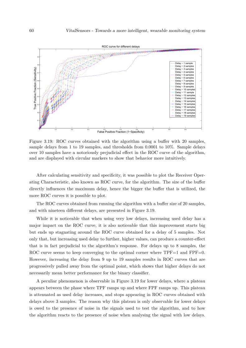
60 VitalSensors - Towards a more intelligent, wearable monitoring system
Figure 3.19: ROC curves obtained with the algorithm using a buffer with 20 samples,sample delays from 1 to 19 samples, and thresholds from 0.0001 to 10%. Sample delaysover 10 samples have a notoriously prejudicial effect in the ROC curve of the algorithm,and are displayed with circular markers to show that behavior more intuitively.
After calculating sensitivity and specificity, it was possible to plot the Receiver Oper-ating Characteristic, also known as ROC curve, for the algorithm. The size of the bufferdirectly influences the maximum delay, hence the bigger the buffer that is utilized, themore ROC curves it is possible to plot.
The ROC curves obtained from running the algorithm with a buffer size of 20 samples,and with nineteen different delays, are presented in Figure 3.19.
While it is noticeable that when using very low delays, increasing used delay has amajor impact on the ROC curve, it is also noticeable that this improvement starts bigbut ends up stagnating around the ROC curve obtained for a delay of 5 samples. Notonly that, but increasing used delay to further, higher values, can produce a counter-effectthat is in fact prejudicial to the algorithm’s response. For delays up to 8 samples, theROC curve seems to keep converging to the optimal corner where TPF=1 and FPF=0.However, increasing the delay from 9 up to 19 samples results in ROC curves that areprogressively pulled away from the optimal point, which shows that higher delays do notnecessarily mean better performance for the binary classifier.
A peculiar phenomenon is observable in Figure 3.19 for lower delays, where a plateauappears between the phase where TPF ramps up and where FPF ramps up. This plateauis attenuated as used delay increases, and stops appearing in ROC curves obtained withdelays above 3 samples. The reason why this plateau is only observable for lower delaysis owed to the presence of noise in the signals used to test the algorithm, and to howthe algorithm reacts to the presence of noise when analysing the signal with low delays.
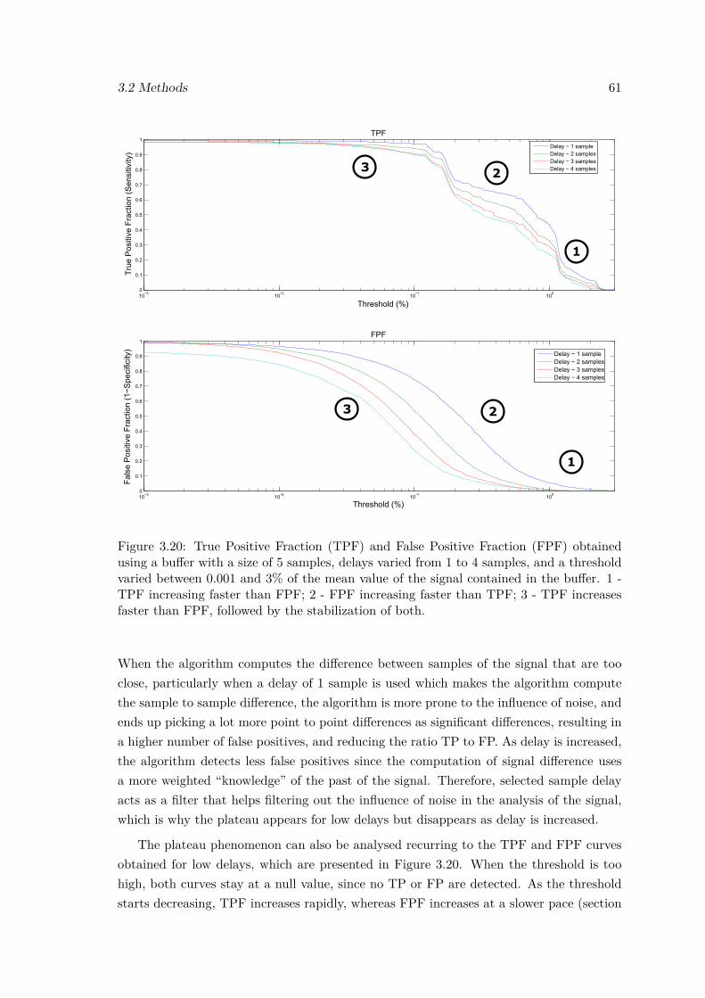
3.2 Methods 61
1
23
1
23
Figure 3.20: True Positive Fraction (TPF) and False Positive Fraction (FPF) obtainedusing a buffer with a size of 5 samples, delays varied from 1 to 4 samples, and a thresholdvaried between 0.001 and 3% of the mean value of the signal contained in the buffer. 1 -TPF increasing faster than FPF; 2 - FPF increasing faster than TPF; 3 - TPF increasesfaster than FPF, followed by the stabilization of both.
When the algorithm computes the difference between samples of the signal that are tooclose, particularly when a delay of 1 sample is used which makes the algorithm computethe sample to sample difference, the algorithm is more prone to the influence of noise, andends up picking a lot more point to point differences as significant differences, resulting ina higher number of false positives, and reducing the ratio TP to FP. As delay is increased,the algorithm detects less false positives since the computation of signal difference usesa more weighted “knowledge” of the past of the signal. Therefore, selected sample delayacts as a filter that helps filtering out the influence of noise in the analysis of the signal,which is why the plateau appears for low delays but disappears as delay is increased.
The plateau phenomenon can also be analysed recurring to the TPF and FPF curvesobtained for low delays, which are presented in Figure 3.20. When the threshold is toohigh, both curves stay at a null value, since no TP or FP are detected. As the thresholdstarts decreasing, TPF increases rapidly, whereas FPF increases at a slower pace (section
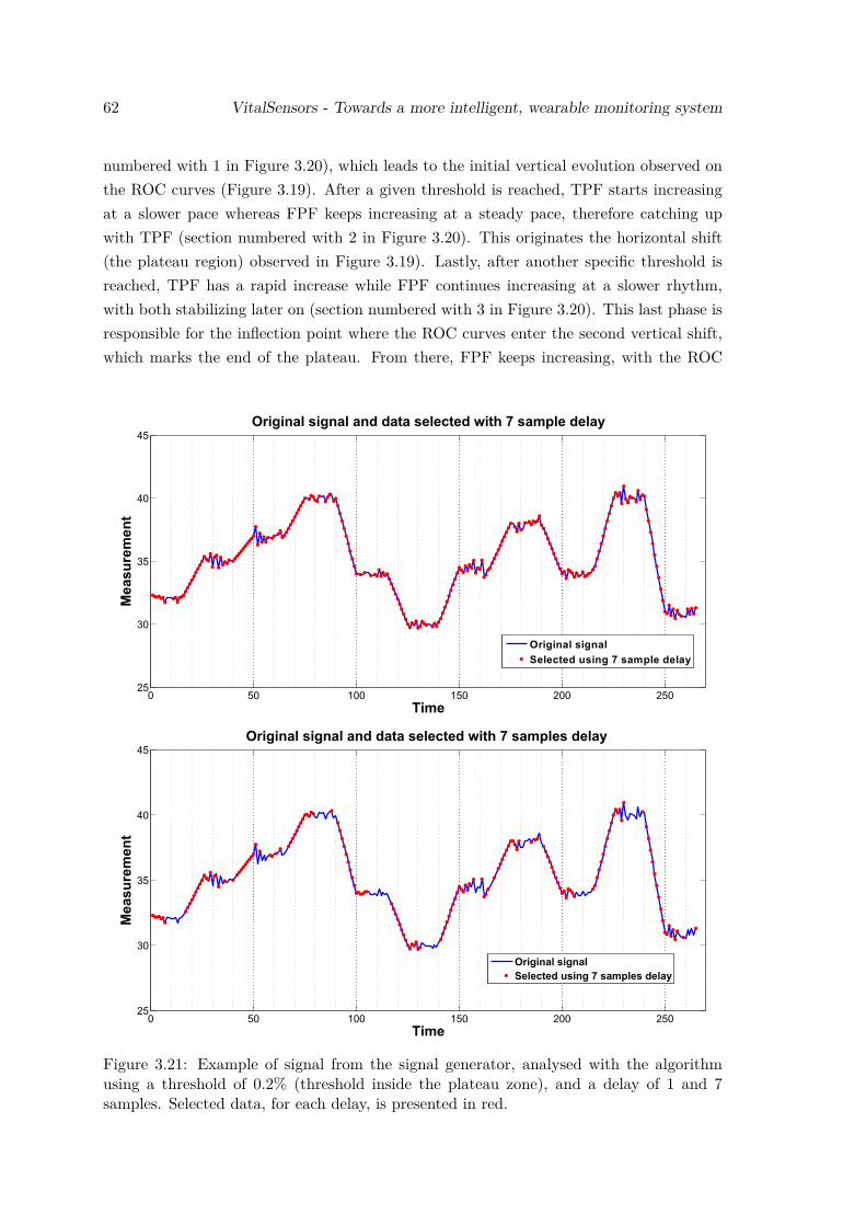
62 VitalSensors - Towards a more intelligent, wearable monitoring system
numbered with 1 in Figure 3.20), which leads to the initial vertical evolution observed onthe ROC curves (Figure 3.19). After a given threshold is reached, TPF starts increasingat a slower pace whereas FPF keeps increasing at a steady pace, therefore catching upwith TPF (section numbered with 2 in Figure 3.20). This originates the horizontal shift(the plateau region) observed in Figure 3.19). Lastly, after another specific threshold isreached, TPF has a rapid increase while FPF continues increasing at a slower rhythm,with both stabilizing later on (section numbered with 3 in Figure 3.20). This last phase isresponsible for the inflection point where the ROC curves enter the second vertical shift,which marks the end of the plateau. From there, FPF keeps increasing, with the ROC
Figure 3.21: Example of signal from the signal generator, analysed with the algorithmusing a threshold of 0.2% (threshold inside the plateau zone), and a delay of 1 and 7samples. Selected data, for each delay, is presented in red.
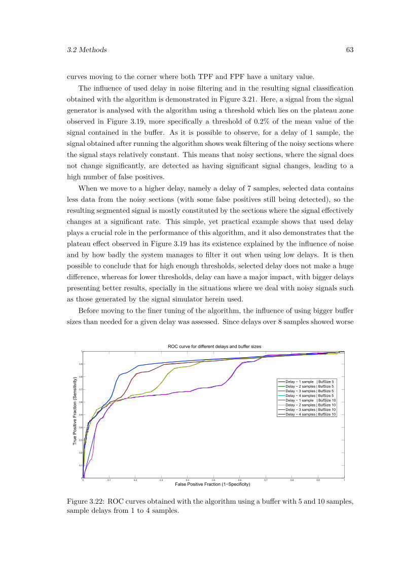
3.2 Methods 63
curves moving to the corner where both TPF and FPF have a unitary value.The influence of used delay in noise filtering and in the resulting signal classification
obtained with the algorithm is demonstrated in Figure 3.21. Here, a signal from the signalgenerator is analysed with the algorithm using a threshold which lies on the plateau zoneobserved in Figure 3.19, more specifically a threshold of 0.2% of the mean value of thesignal contained in the buffer. As it is possible to observe, for a delay of 1 sample, thesignal obtained after running the algorithm shows weak filtering of the noisy sections wherethe signal stays relatively constant. This means that noisy sections, where the signal doesnot change significantly, are detected as having significant signal changes, leading to ahigh number of false positives.
When we move to a higher delay, namely a delay of 7 samples, selected data containsless data from the noisy sections (with some false positives still being detected), so theresulting segmented signal is mostly constituted by the sections where the signal effectivelychanges at a significant rate. This simple, yet practical example shows that used delayplays a crucial role in the performance of this algorithm, and it also demonstrates that theplateau effect observed in Figure 3.19 has its existence explained by the influence of noiseand by how badly the system manages to filter it out when using low delays. It is thenpossible to conclude that for high enough thresholds, selected delay does not make a hugedifference, whereas for lower thresholds, delay can have a major impact, with bigger delayspresenting better results, specially in the situations where we deal with noisy signals suchas those generated by the signal simulator herein used.
Before moving to the finer tuning of the algorithm, the influence of using bigger buffersizes than needed for a given delay was assessed. Since delays over 8 samples showed worse
Figure 3.22: ROC curves obtained with the algorithm using a buffer with 5 and 10 samples,sample delays from 1 to 4 samples.
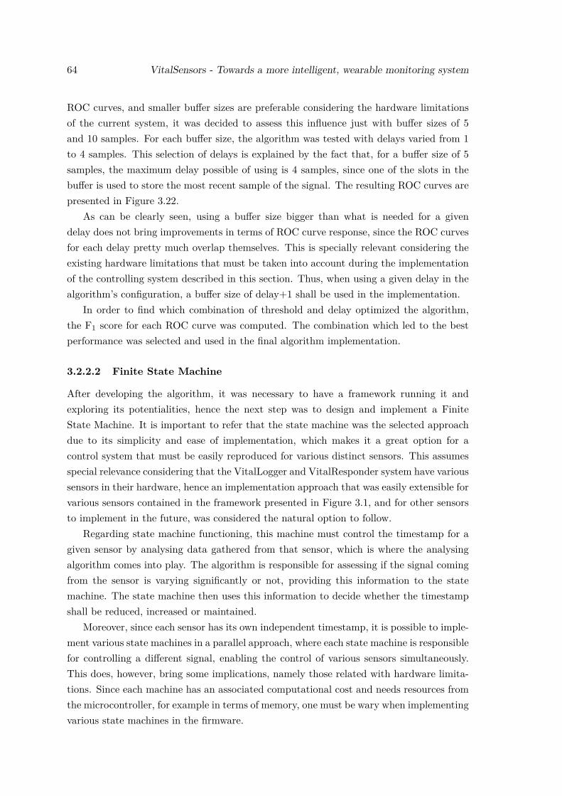
64 VitalSensors - Towards a more intelligent, wearable monitoring system
ROC curves, and smaller buffer sizes are preferable considering the hardware limitationsof the current system, it was decided to assess this influence just with buffer sizes of 5and 10 samples. For each buffer size, the algorithm was tested with delays varied from 1to 4 samples. This selection of delays is explained by the fact that, for a buffer size of 5samples, the maximum delay possible of using is 4 samples, since one of the slots in thebuffer is used to store the most recent sample of the signal. The resulting ROC curves arepresented in Figure 3.22.
As can be clearly seen, using a buffer size bigger than what is needed for a givendelay does not bring improvements in terms of ROC curve response, since the ROC curvesfor each delay pretty much overlap themselves. This is specially relevant considering theexisting hardware limitations that must be taken into account during the implementationof the controlling system described in this section. Thus, when using a given delay in thealgorithm’s configuration, a buffer size of delay+1 shall be used in the implementation.
In order to find which combination of threshold and delay optimized the algorithm,the F1 score for each ROC curve was computed. The combination which led to the bestperformance was selected and used in the final algorithm implementation.
3.2.2.2 Finite State Machine
After developing the algorithm, it was necessary to have a framework running it andexploring its potentialities, hence the next step was to design and implement a FiniteState Machine. It is important to refer that the state machine was the selected approachdue to its simplicity and ease of implementation, which makes it a great option for acontrol system that must be easily reproduced for various distinct sensors. This assumesspecial relevance considering that the VitalLogger and VitalResponder system have varioussensors in their hardware, hence an implementation approach that was easily extensible forvarious sensors contained in the framework presented in Figure 3.1, and for other sensorsto implement in the future, was considered the natural option to follow.
Regarding state machine functioning, this machine must control the timestamp for agiven sensor by analysing data gathered from that sensor, which is where the analysingalgorithm comes into play. The algorithm is responsible for assessing if the signal comingfrom the sensor is varying significantly or not, providing this information to the statemachine. The state machine then uses this information to decide whether the timestampshall be reduced, increased or maintained.
Moreover, since each sensor has its own independent timestamp, it is possible to imple-ment various state machines in a parallel approach, where each state machine is responsiblefor controlling a different signal, enabling the control of various sensors simultaneously.This does, however, bring some implications, namely those related with hardware limita-tions. Since each machine has an associated computational cost and needs resources fromthe microcontroller, for example in terms of memory, one must be wary when implementingvarious state machines in the firmware.
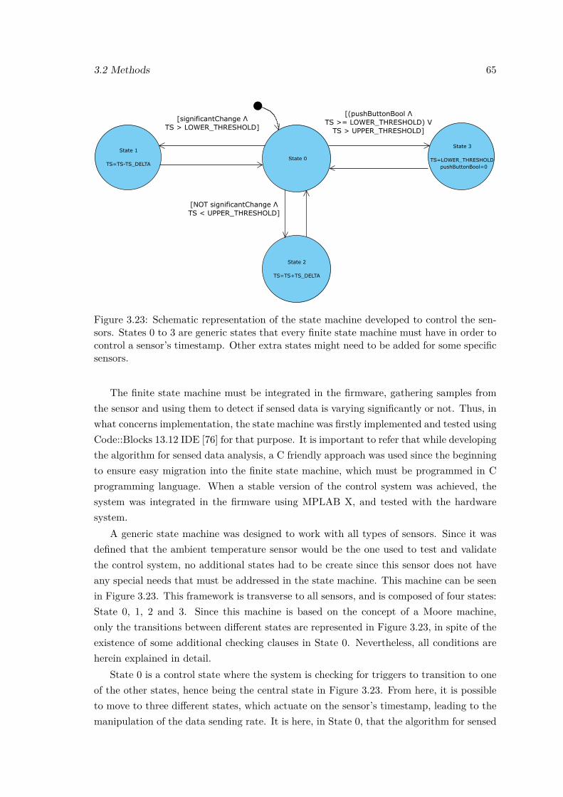
3.2 Methods 65
State 0
State 1
TS=TS-TS_DELTA
State 2
TS=TS+TS_DELTA
State 3
TS=LOWER_THRESHOLDpushButtonBool=0
[(pushButtonBool ΛTS >= LOWER_THRESHOLD) V
TS > UPPER_THRESHOLD]
[significantChange ΛTS > LOWER_THRESHOLD]
[NOT significantChange ΛTS < UPPER_THRESHOLD]
Figure 3.23: Schematic representation of the state machine developed to control the sen-sors. States 0 to 3 are generic states that every finite state machine must have in order tocontrol a sensor’s timestamp. Other extra states might need to be added for some specificsensors.
The finite state machine must be integrated in the firmware, gathering samples fromthe sensor and using them to detect if sensed data is varying significantly or not. Thus, inwhat concerns implementation, the state machine was firstly implemented and tested usingCode::Blocks 13.12 IDE [76] for that purpose. It is important to refer that while developingthe algorithm for sensed data analysis, a C friendly approach was used since the beginningto ensure easy migration into the finite state machine, which must be programmed in Cprogramming language. When a stable version of the control system was achieved, thesystem was integrated in the firmware using MPLAB X, and tested with the hardwaresystem.
A generic state machine was designed to work with all types of sensors. Since it wasdefined that the ambient temperature sensor would be the one used to test and validatethe control system, no additional states had to be create since this sensor does not haveany special needs that must be addressed in the state machine. This machine can be seenin Figure 3.23. This framework is transverse to all sensors, and is composed of four states:State 0, 1, 2 and 3. Since this machine is based on the concept of a Moore machine,only the transitions between different states are represented in Figure 3.23, in spite of theexistence of some additional checking clauses in State 0. Nevertheless, all conditions areherein explained in detail.
State 0 is a control state where the system is checking for triggers to transition to oneof the other states, hence being the central state in Figure 3.23. From here, it is possibleto move to three different states, which actuate on the sensor’s timestamp, leading to themanipulation of the data sending rate. It is here, in State 0, that the algorithm for sensed
66 VitalSensors - Towards a more intelligent, wearable monitoring system
data analysis is run, having to be fed with incoming samples measured by the sensor. Thearrow above State 0, that can be seen in Figure 3.23, means that this is the state wherethe state machine is initialized.
State 1 is the state responsible for lowering the timestamp controllably, which lets moredata be sent. In order to transition to this state, the algorithm on State 0 must detectthat the signal measured by the sensor is varying significantly. Moreover, the timestamphas a lower threshold which defines the minimum possible timestamp for the sensor. Itmust only be possible to get to State 1 if the timestamp is higher than this threshold, sothat the timestamp is not lowered beyond what the system can comply with.
State 2 is exactly the opposite of State 1, in the sense that it is the state responsiblefor increasing the timestamp in controlled increments, which results in fewer data beingsent (data is more spaced in time). Here, instead of looking for significant changes inthe measured signal, the system is actually looking for situations where the signal is notchanging significantly, as is the case when the signal is quasi-constant. Similarly to State 1,there is a threshold restricting the change of the timestamp, except that now it is an upperthreshold, that defines the maximum possible timestamp for the sensor. This thresholdlimits how slow the “data sending rate” can be, so that sensed data sent in the datagramis not overly spaced in time.
State 3 was implemented so that in the presence of a specific event, such as the detectionof a dangerous situation, the user can force the system to send sensed data at the “fastestrate” possible. This was implemented by taking advantage of the button that exists inVitalJacket’s box. For this purpose, a boolean variable that controls button presses wascreated outside the state machine. When the button is pressed by the user, the buttonhandler function in the firmware sets the boolean variable to true, signaling that there is anexisting button press to be handled. The state machine checks this variable, so that whenit is true, the machine transitions to Stage 3 and forces timestamp’s value to that of thelower threshold. After having the timestamp changed, the boolean variable that controlsbutton presses is reset to false. Since the machine can only actuate on the timestamp if itscurrent value is higher than the lower threshold, the check condition was defined so thatwhen the button is pressed and the timestamp is already at the lowest possible value, thesystem resets the boolean variable to false and maintains the timestamp unchanged.
As it was referred previously, aside from the states and transitions presented in Fig-ure 3.23, two other checking conditions had to be introduced in Stage 0 to ensure properfunctioning of the system. The first condition was created to ensure that the system doesnot increment past the upper threshold. This condition checks if measured signal changeis not significant and if the timestamp is already at the maximum value. If this situationis detected, this condition stops the system from incrementing the timestamp beyond theupper threshold’s value. On the other hand, the second condition is responsible for control-ling the other extreme of timestamp values, ensuring that the system does not decrementthe timestamp past the lower threshold. Here, the condition checks if the signal is chang-
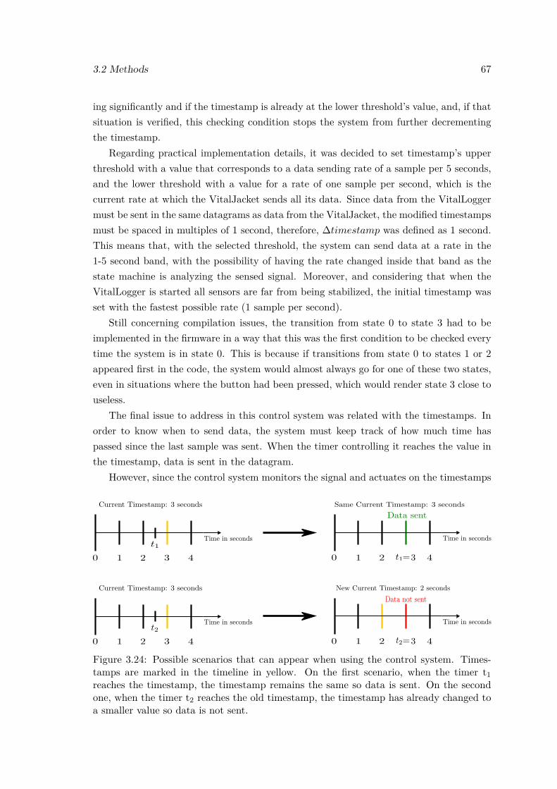
3.2 Methods 67
ing significantly and if the timestamp is already at the lower threshold’s value, and, if thatsituation is verified, this checking condition stops the system from further decrementingthe timestamp.
Regarding practical implementation details, it was decided to set timestamp’s upperthreshold with a value that corresponds to a data sending rate of a sample per 5 seconds,and the lower threshold with a value for a rate of one sample per second, which is thecurrent rate at which the VitalJacket sends all its data. Since data from the VitalLoggermust be sent in the same datagrams as data from the VitalJacket, the modified timestampsmust be spaced in multiples of 1 second, therefore, ∆timestamp was defined as 1 second.This means that, with the selected threshold, the system can send data at a rate in the1-5 second band, with the possibility of having the rate changed inside that band as thestate machine is analyzing the sensed signal. Moreover, and considering that when theVitalLogger is started all sensors are far from being stabilized, the initial timestamp wasset with the fastest possible rate (1 sample per second).
Still concerning compilation issues, the transition from state 0 to state 3 had to beimplemented in the firmware in a way that this was the first condition to be checked everytime the system is in state 0. This is because if transitions from state 0 to states 1 or 2appeared first in the code, the system would almost always go for one of these two states,even in situations where the button had been pressed, which would render state 3 close touseless.
The final issue to address in this control system was related with the timestamps. Inorder to know when to send data, the system must keep track of how much time haspassed since the last sample was sent. When the timer controlling it reaches the value inthe timestamp, data is sent in the datagram.
However, since the control system monitors the signal and actuates on the timestamps
Figure 3.24: Possible scenarios that can appear when using the control system. Times-tamps are marked in the timeline in yellow. On the first scenario, when the timer t1reaches the timestamp, the timestamp remains the same so data is sent. On the secondone, when the timer t2 reaches the old timestamp, the timestamp has already changed toa smaller value so data is not sent.

68 VitalSensors - Towards a more intelligent, wearable monitoring system
at a faster rate than data is sent by the system, before the timer gets to the time point inthe timestamp, that timestamp might have changed to different values various times. Ifthe new timestamp has its value maintained or if its value corresponds to a time higherthan the time contained in the timer, the system just keeps working until that timestampis reached, sending data when it hits that time. This is the first case represented inFigure 3.24.
On the other hand, if by the time the timer reaches the old timestamp, the timestamphas changed to a value that corresponds to a time in the past (which the timer has alreadypassed), the system will not send the data because it is not prepared to do so. This secondcase is also depicted in Figure 3.24. To overcome this issue, the existing system’s firmwarehad to be changed so that when the second case occurs, data is sent by the system on thenext datagram to be sent with data from other sensors.
After developing the state machine in Code::Blocks IDE, tests were performed onthe command line, in order to debug the state machine before implementing it in thefirmware. In order to simulate the press of the button, a specific value of 20 was set tosimulate the act of pressing the button in the physical system. Figure 3.25 demonstratesthe state machine running with measurements that are given to the machine manuallyby the user. The graphical interface showed in Figure 3.25 firstly prompts the user toinsert the new measurement. After introducing the measurement, the interface showsthe classification result (1 for a significant change, 0 for a non-significant one), the newly
Figure 3.25: Demonstration of the implemented state machine, before implementing inthe firmware. The transition to State 3, which is triggered by pressing VJ’s button, wassimulated by configuring a specific SpO2 value (20 in this case) to work as the button inthe real system.
3.2 Methods 69
introduced measurement, the calculated change in the signal, and the buffer with thesamples contained in it.
The first box shows a case where the signal starts by changing not significantly, whichleads to a transition to state 2 and an increase in the timestamp, followed by a significantchange, which leads to a transition to state 1 and a decrease in the timestamp.
The second box presents a case where the signal is also changing not significantly, withthe timestamp reaching its maximum possible value. Then, a value of 20 is introduced tosimulate the act of pressing the button in VJ’s box, which triggers a transition to state 3,and a decrease in the timestamp directly to the lowest possible value.
While Figure 3.25 presents just a relatively small demonstration of how the statemachine works, it portraits the workflow where the state machine can transition fromstate 0 to one of the 3 other states, or just stay in state 0 in case none of the statetransitions is triggered.
The final system, responsible for the intelligent data reduction, was implemented specif-ically for the ambient temperature signal. For that purpose, the designed state machinewas implemented with the threshold verification condition (which checks if the signal iswithin the safe limits). With this system, when ambient temperature steps out the saferange of values, the machine uses the developed algorithm to analyse if the signal is chang-ing significantly or not, and adjusts the amount of data to select accordingly.
3.2.3 Non Perceptible Physiological Indicators
The final step of this thesis consisted in obtaining relevant information for first responders,that is either hard or impossible to measure using sensors, and that can be provided in anintuitive way to give better knowledge on the first responders using the wearable system.
Stress and fatigue are important physiological measures for the first responders thatcannot be acquired using sensors, thus being hard to obtain. However, there are indicators,such as the Physiological Strain Index (PSI) that is used to evaluate heat stress, whichcan be obtained from other vital signs. In fact, PSI has already been implemented in somesystems, mostly for military uses, as presented in literature [77].
PSI can be obtained using heart rate and core temperature measurements. The prob-lem with estimating PSI is that there is currently no completely non-invasive way to sensecore temperature. The gold standard for measuring core temperature consists in usinga rectal probe, which is not practical and comfortable for first responders to use whileworking, thus not being a viable option to be implemented in a wearable system likeVitalResponder.
Moreover, core temperature, on its own, can be used as a good indicator of physiologicalstatus to prevent/minimize physiological strain [78], with literature referring that workersshould not be permitted to work when their core temperature exceeds 38◦C [75]. Therefore,it is important to extract core temperature and PSI from sensed data, as this is relevant
70 VitalSensors - Towards a more intelligent, wearable monitoring system
information that can be implemented on alarm systems, which are known to be moreuseful than the measurements themselves for the Fire Chief.
In what concerns the extraction of core temperature from currently sensed data, thereare two main novel non-invasive approaches described in literature, which exploit thefact that when thermoregulation mechanisms begin to fail, variables like heart rate andskin temperature correlate more directly with core temperature. First responders arefrequently subject to harsh conditions and heavy physical exertion, and are thus a greattarget population for these approaches.
The first approach is more sensor dependent, and estimates core temperature usingdata acquired from various sensors such as skin temperature, heat flux and ambient tem-perature sensors. Despite showing promising results, it is complex and requires specificequipment to be developed for this purpose [61, 54, 79].
The second approach is based on a Kalman filter that estimates core temperaturefrom heart rate measurements, and was developed with the aim of creating a simpler andpractical system that only requires a single input, and that can easily be deployed inambulatory field settings. This method showed good results and also holds great promisefor the near future [55, 56]. In fact, it has already been implemented by ZephyrTM in acommercialized solution for First Responders, the BioHarnessTM [24, 22], and there existsliterature supporting that core temperature estimates from BioHarnessTM can be used asa reliable surrogate measurement of core temperature in the field setting [78].
Since PSI can be easily obtained using heart rate and core temperature measurements,the challenging part of this step of the work is to develop a robust core temperature pre-dictor. In this step of the thesis, it was decided to implement a Kalman filter predictor,using MATLAB software, to obtain core temperature estimations from heart rate mea-surements. The Kalman filter was the selected approach because of its relative simplicityand inherent properties that make it a great tool for prediction systems.
Core temperature estimations obtained from the implemented predictor were used tocompute the Physiological Strain Index. In order to develop the predicting system, it wasfirstly necessary to have access to a database with the needed information, and to processthat data before using it. All these aspects will now be discussed in detail.
3.2.3.1 Assembling a Dataset
The first issue of this part of the work to be addressed, was to have access to a databasewith information from various vital signs, namely from heart rate and rectal temperature.The reason why rectal temperature, obtained with a rectal probe, is a must have whendeveloping a system with the purpose of predicting core temperature, is because it isconsidered the gold standard for assessing core temperature. Therefore, in order to beable to evaluate the performance of the implemented system, it is crucial to have thisground truth for comparison.
3.2 Methods 71
Access to data for this step of the work was granted by Aitor Coca, from NIOSH/CDC,Pittsburgh, Pennsylvania. This data was acquired in a study which had the intent ofassessing the viability of a core temperature estimating system, in this specific case theBioHarnessTM that estimates core temperature from heart rate, under several heat stressconditions [78].
This data was obtained in thermoneutral and in heat stress conditions (high tempera-ture and relative humidity), simulating the hazardous environmental conditions that firstresponders often face when working. 12 healthy men were used in these experiment sets,and four different conditions were simulated: control, active, passive and with personalprotective equipment. In these experimental sets, heat stress and exercise conditions towhich individuals were subjected were varied, and the termination criteria was a rise inrectal temperature of 1.5◦C. Access was only given to data from control, passive and activeconditions.
In order to acquire the physiological signals, subjects were instrumented with thefollowing sensors: a rectal probe to measure rectal temperature, skin temperature sensorsand heat flux sensors. These last two types of sensors were placed in five different bodysites (forehead, chest, shoulder, thigh and calf). Finally, a BioHarnessTM was used tomeasure heart rate and to provide core temperature estimates. For the sake of simplicity,the system with the rectal probe, skin temperature and heat flux sensors will be referredto as system A, and the BioHarness system will be referred to as system B. Both systemswere used simultaneously during the tests. System A was operated at a sampling rate of0.5Hz, whereas system B was operated at a sampling rate of 0.4Hz.
After having access to the files with data from these experiments, the first step was toextract data to MATLAB, and process it so that it could be used for the implementationof the Kalman filter predicting system. In order to be able to compare measurements fromboth sensing systems, it was necessary to adjust the sampling rate of the data from oneof the systems, so that it matched the sampling rate of the other system. In this thesis,it was opted to downsample the longer signals, which were those obtained with the rectalprobe, skin temperature and heat flux sensors. This was performed using the resamplefunction from MATLAB.
Figure 3.26 presents a resampled rectal temperature signal, which is from the systemwith higher sampling rate, and an original estimated core temperature signal, which isfrom the system with lower sampling rate. It can be noticed that both signals matchrelatively well in terms of time, which enables direct comparison of signals from bothsystems, namely between estimated core temperature and rectal and/or skin temperature.
Despite the good signal matching that can be seen in Figure 3.26, using MATLAB’sresample function to downsample the longer signal generated another issue, related withartifact creation. This phenomenon is shown in Figure 3.27. In order to solve this issue, allsignals had a fixed number of samples trimmed off both at the beginning and end sectionsof the signal. The number of samples to be trimmed off was set at 10 samples at both
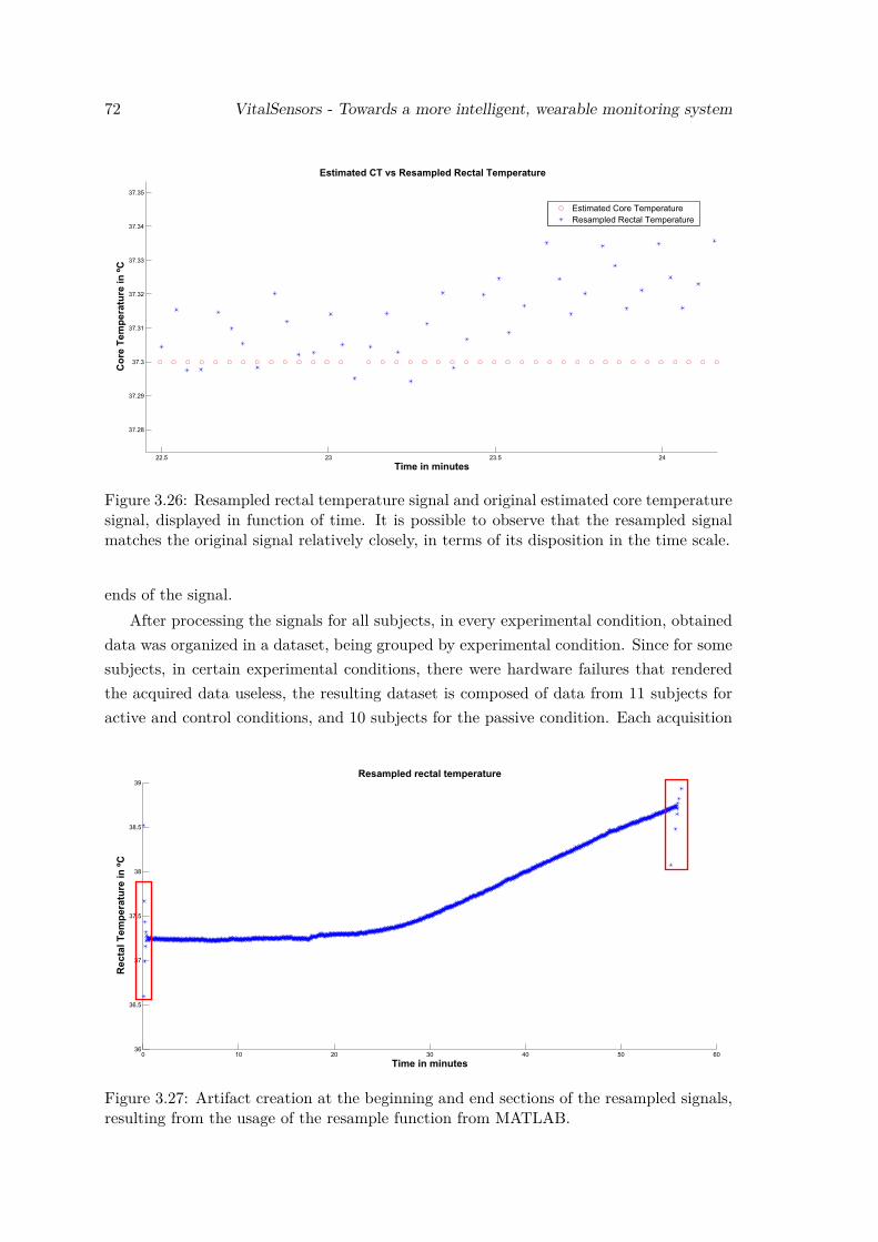
72 VitalSensors - Towards a more intelligent, wearable monitoring system
Figure 3.26: Resampled rectal temperature signal and original estimated core temperaturesignal, displayed in function of time. It is possible to observe that the resampled signalmatches the original signal relatively closely, in terms of its disposition in the time scale.
ends of the signal.After processing the signals for all subjects, in every experimental condition, obtained
data was organized in a dataset, being grouped by experimental condition. Since for somesubjects, in certain experimental conditions, there were hardware failures that renderedthe acquired data useless, the resulting dataset is composed of data from 11 subjects foractive and control conditions, and 10 subjects for the passive condition. Each acquisition
Figure 3.27: Artifact creation at the beginning and end sections of the resampled signals,resulting from the usage of the resample function from MATLAB.
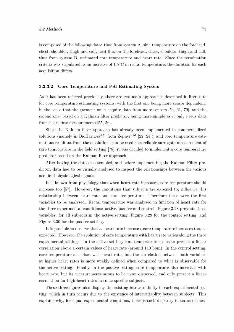
3.2 Methods 73
is composed of the following data: time from system A, skin temperature on the forehead,chest, shoulder, thigh and calf, heat flux on the forehead, chest, shoulder, thigh and calf,time from system B, estimated core temperature and heart rate. Since the terminationcriteria was stipulated as an increase of 1.5◦C in rectal temperature, the duration for eachacquisition differs.
3.2.3.2 Core Temperature and PSI Estimating System
As it has been referred previously, there are two main approaches described in literaturefor core temperature estimating systems, with the first one being more sensor dependent,in the sense that the garment must acquire data from more sensors [54, 61, 79], and thesecond one, based on a Kalman filter predictor, being more simple as it only needs datafrom heart rate measurements [55, 56].
Since the Kalman filter approach has already been implemented in commercializedsolutions (namely in BioHarnessTM from ZephyrTM [22, 24]), and core temperature esti-mations resultant from these solutions can be used as a reliable surrogate measurement ofcore temperature in the field setting [78], it was decided to implement a core temperaturepredictor based on the Kalman filter approach.
After having the dataset assembled, and before implementing the Kalman Filter pre-dictor, data had to be visually analysed to inspect the relationships between the variousacquired physiological signals.
It is known from physiology that when heart rate increases, core temperature shouldincrease too [57]. However, the conditions that subjects are exposed to, influence thisrelationship between heart rate and core temperature. Therefore these were the firstvariables to be analysed. Rectal temperature was analyzed in function of heart rate forthe three experimental conditions: active, passive and control. Figure 3.28 presents thosevariables, for all subjects in the active setting, Figure 3.29 for the control setting, andFigure 3.30 for the passive setting.
It is possible to observe that as heart rate increases, core temperature increases too, asexpected. However, the evolution of core temperature with heart rate varies along the threeexperimental settings. In the active setting, core temperature seems to present a linearcorrelation above a certain values of heart rate (around 140 bpm). In the control setting,core temperature also rises with heart rate, but the correlation between both variablesat higher heart rates is more weakly defined when compared to what is observable forthe active setting. Finally, in the passive setting, core temperature also increases withheart rate, but its measurements seems to be more dispersed, and only present a linearcorrelation for high heart rates in some specific subjects.
These three figures also display the existing intravariability in each experimental set-ting, which in turn occurs due to the existence of intervariablity between subjects. Thisexplains why, for equal experimental conditions, there is such disparity in terms of mea-
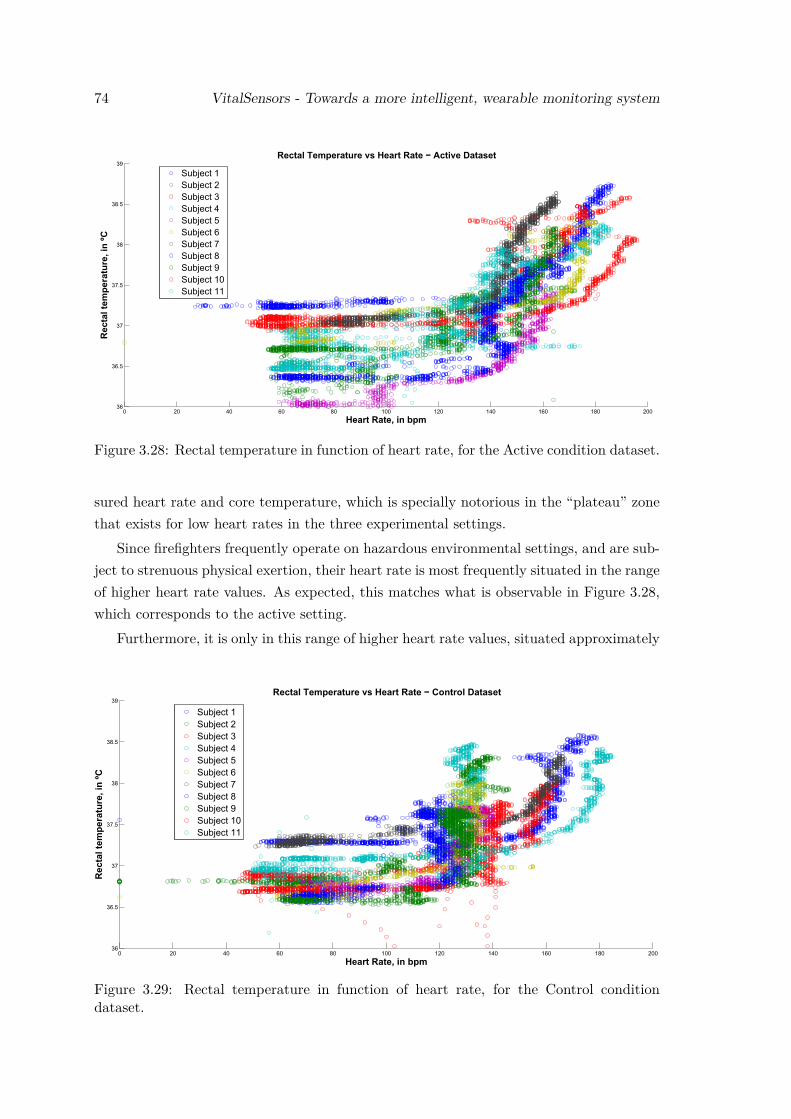
74 VitalSensors - Towards a more intelligent, wearable monitoring system
Figure 3.28: Rectal temperature in function of heart rate, for the Active condition dataset.
sured heart rate and core temperature, which is specially notorious in the “plateau” zonethat exists for low heart rates in the three experimental settings.
Since firefighters frequently operate on hazardous environmental settings, and are sub-ject to strenuous physical exertion, their heart rate is most frequently situated in the rangeof higher heart rate values. As expected, this matches what is observable in Figure 3.28,which corresponds to the active setting.
Furthermore, it is only in this range of higher heart rate values, situated approximately
Figure 3.29: Rectal temperature in function of heart rate, for the Control conditiondataset.
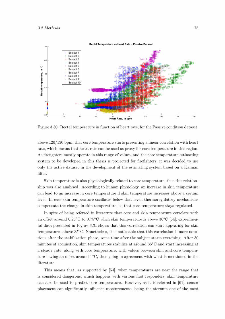
3.2 Methods 75
Figure 3.30: Rectal temperature in function of heart rate, for the Passive condition dataset.
above 120/130 bpm, that core temperature starts presenting a linear correlation with heartrate, which means that heart rate can be used as proxy for core temperature in this region.As firefighters mostly operate in this range of values, and the core temperature estimatingsystem to be developed in this thesis is projected for firefighters, it was decided to useonly the active dataset in the development of the estimating system based on a Kalmanfilter.
Skin temperature is also physiologically related to core temperature, thus this relation-ship was also analysed. According to human physiology, an increase in skin temperaturecan lead to an increase in core temperature if skin temperature increases above a certainlevel. In case skin temperature oscillates below that level, thermoregulatory mechanismscompensate the change in skin temperature, so that core temperature stays regulated.
In spite of being referred in literature that core and skin temperature correlate withan offset around 0.25◦C to 0.75◦C when skin temperature is above 36◦C [54], experimen-tal data presented in Figure 3.31 shows that this correlation can start appearing for skintemperatures above 35◦C. Nonetheless, it is noticeable that this correlation is more noto-rious after the stabilization phase, some time after the subject starts exercising. After 30minutes of acquisition, skin temperatures stabilize at around 35◦C and start increasing ata steady rate, along with core temperature, with values between skin and core tempera-ture having an offset around 1◦C, thus going in agreement with what is mentioned in theliterature.
This means that, as supported by [54], when temperatures are near the range thatis considered dangerous, which happens with various first responders, skin temperaturecan also be used to predict core temperature. However, as it is referred in [61], sensorplacement can significantly influence measurements, being the sternum one of the most
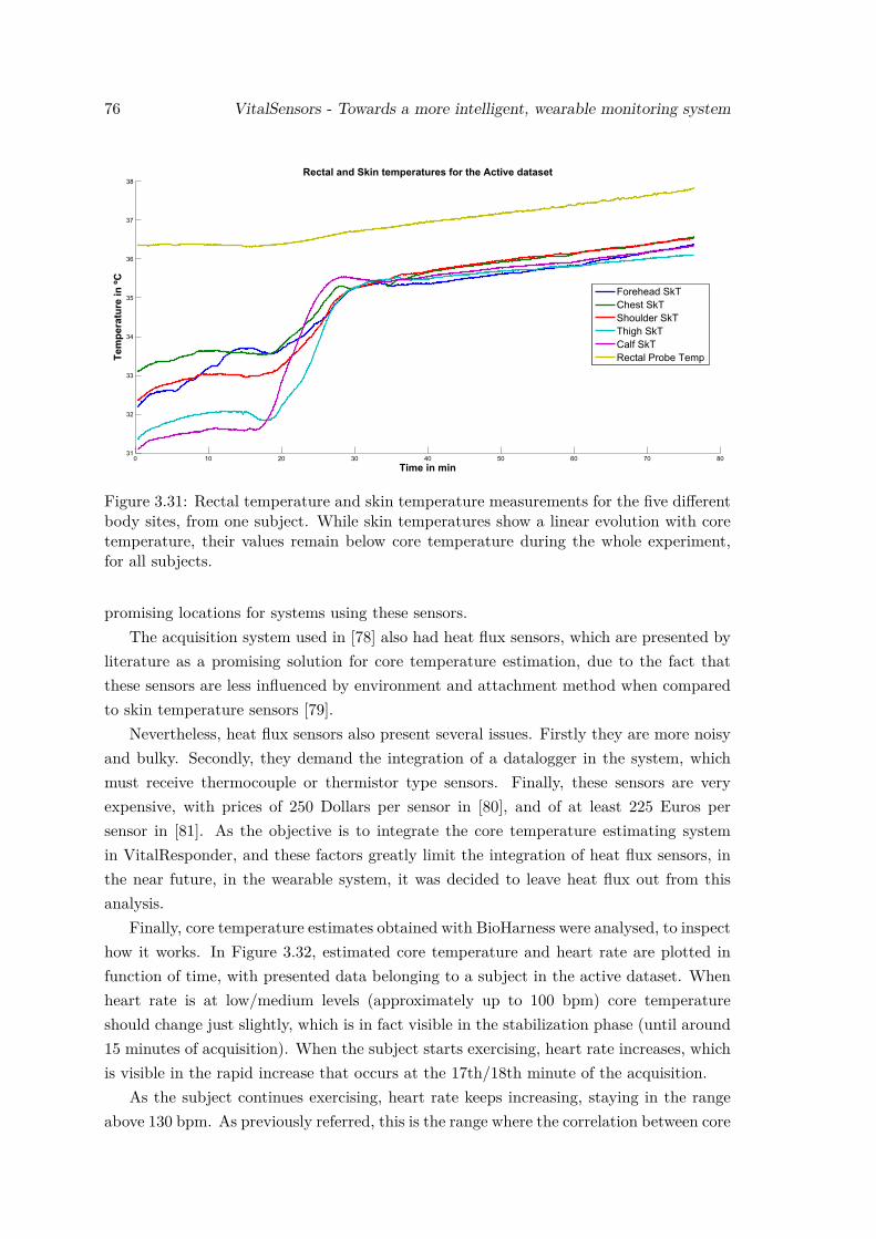
76 VitalSensors - Towards a more intelligent, wearable monitoring system
Figure 3.31: Rectal temperature and skin temperature measurements for the five differentbody sites, from one subject. While skin temperatures show a linear evolution with coretemperature, their values remain below core temperature during the whole experiment,for all subjects.
promising locations for systems using these sensors.The acquisition system used in [78] also had heat flux sensors, which are presented by
literature as a promising solution for core temperature estimation, due to the fact thatthese sensors are less influenced by environment and attachment method when comparedto skin temperature sensors [79].
Nevertheless, heat flux sensors also present several issues. Firstly they are more noisyand bulky. Secondly, they demand the integration of a datalogger in the system, whichmust receive thermocouple or thermistor type sensors. Finally, these sensors are veryexpensive, with prices of 250 Dollars per sensor in [80], and of at least 225 Euros persensor in [81]. As the objective is to integrate the core temperature estimating systemin VitalResponder, and these factors greatly limit the integration of heat flux sensors, inthe near future, in the wearable system, it was decided to leave heat flux out from thisanalysis.
Finally, core temperature estimates obtained with BioHarness were analysed, to inspecthow it works. In Figure 3.32, estimated core temperature and heart rate are plotted infunction of time, with presented data belonging to a subject in the active dataset. Whenheart rate is at low/medium levels (approximately up to 100 bpm) core temperatureshould change just slightly, which is in fact visible in the stabilization phase (until around15 minutes of acquisition). When the subject starts exercising, heart rate increases, whichis visible in the rapid increase that occurs at the 17th/18th minute of the acquisition.
As the subject continues exercising, heart rate keeps increasing, staying in the rangeabove 130 bpm. As previously referred, this is the range where the correlation between core
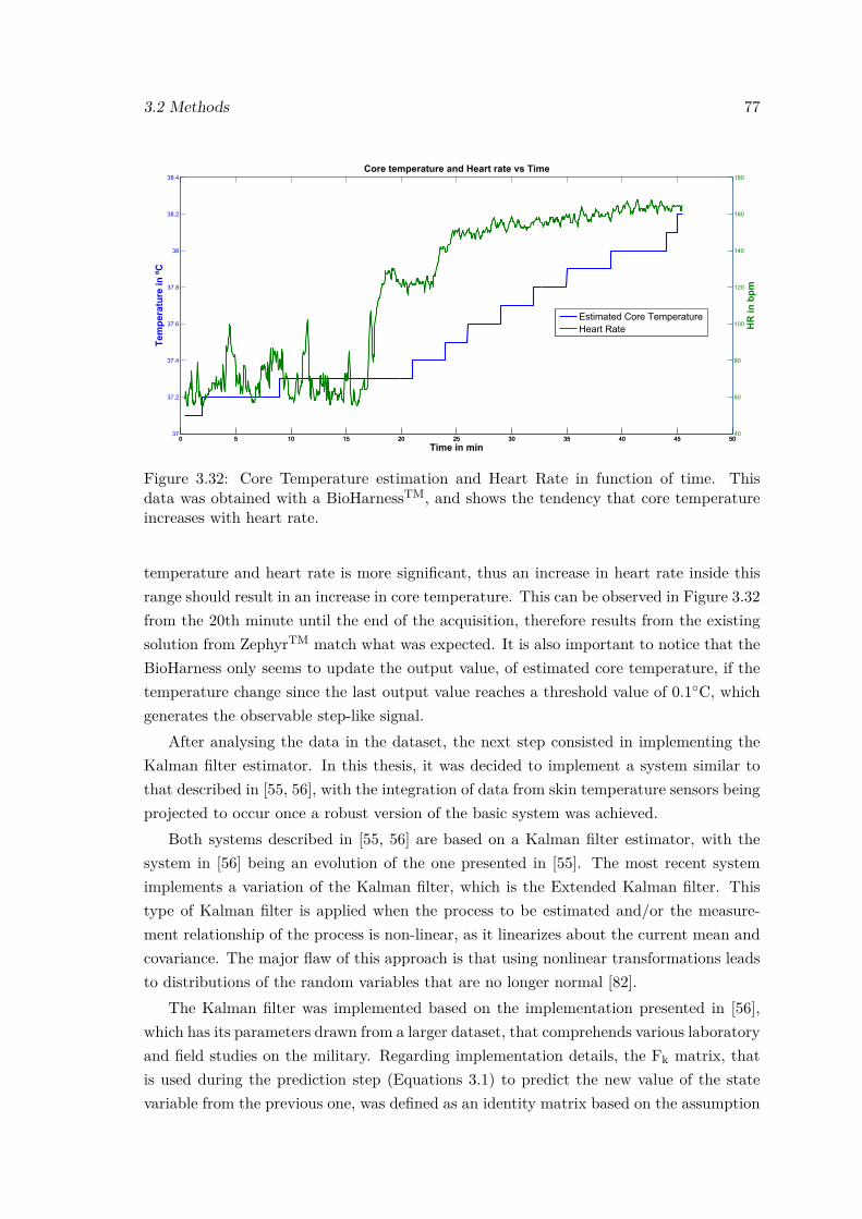
3.2 Methods 77
Figure 3.32: Core Temperature estimation and Heart Rate in function of time. Thisdata was obtained with a BioHarnessTM, and shows the tendency that core temperatureincreases with heart rate.
temperature and heart rate is more significant, thus an increase in heart rate inside thisrange should result in an increase in core temperature. This can be observed in Figure 3.32from the 20th minute until the end of the acquisition, therefore results from the existingsolution from ZephyrTM match what was expected. It is also important to notice that theBioHarness only seems to update the output value, of estimated core temperature, if thetemperature change since the last output value reaches a threshold value of 0.1◦C, whichgenerates the observable step-like signal.
After analysing the data in the dataset, the next step consisted in implementing theKalman filter estimator. In this thesis, it was decided to implement a system similar tothat described in [55, 56], with the integration of data from skin temperature sensors beingprojected to occur once a robust version of the basic system was achieved.
Both systems described in [55, 56] are based on a Kalman filter estimator, with thesystem in [56] being an evolution of the one presented in [55]. The most recent systemimplements a variation of the Kalman filter, which is the Extended Kalman filter. Thistype of Kalman filter is applied when the process to be estimated and/or the measure-ment relationship of the process is non-linear, as it linearizes about the current mean andcovariance. The major flaw of this approach is that using nonlinear transformations leadsto distributions of the random variables that are no longer normal [82].
The Kalman filter was implemented based on the implementation presented in [56],which has its parameters drawn from a larger dataset, that comprehends various laboratoryand field studies on the military. Regarding implementation details, the Fk matrix, thatis used during the prediction step (Equations 3.1) to predict the new value of the statevariable from the previous one, was defined as an identity matrix based on the assumption
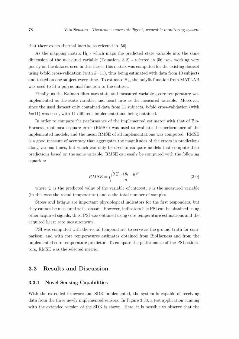
78 VitalSensors - Towards a more intelligent, wearable monitoring system
that there exists thermal inertia, as referred in [56].As the mapping matrix Hk - which maps the predicted state variable into the same
dimension of the measured variable (Equations 3.2) - referred in [56] was working verypoorly on the dataset used in this thesis, this matrix was computed for the existing datasetusing k-fold cross-validation (with k=11), thus being estimated with data from 10 subjectsand tested on one subject every time. To estimate Hk, the polyfit function from MATLABwas used to fit a polynomial function to the dataset.
Finally, as the Kalman filter uses state and measured variables, core temperature wasimplemented as the state variable, and heart rate as the measured variable. Moreover,since the used dataset only contained data from 11 subjects, k-fold cross-validation (withk=11) was used, with 11 different implementations being obtained.
In order to compare the performance of the implemented estimator with that of Bio-Harness, root mean square error (RMSE) was used to evaluate the performance of theimplemented models, and the mean RMSE of all implementations was computed. RMSEis a good measure of accuracy that aggregates the magnitudes of the errors in predictionsalong various times, but which can only be used to compare models that compute theirpredictions based on the same variable. RMSE can easily be computed with the followingequation:
RMSE =
√∑nt=1(yt −y)2
n(3.9)
where yt is the predicted value of the variable of interest, y is the measured variable(in this case the rectal temperature) and n the total number of samples.
Stress and fatigue are important physiological indicators for the first responders, butthey cannot be measured with sensors. However, indicators like PSI can be obtained usingother acquired signals, thus, PSI was obtained using core temperature estimations and theacquired heart rate measurements.
PSI was computed with the rectal temperature, to serve as the ground truth for com-parison, and with core temperatures estimates obtained from BioHarness and from theimplemented core temperature predictor. To compare the performance of the PSI estima-tors, RMSE was the selected metric.
3.3 Results and Discussion
3.3.1 Novel Sensing Capabilities
With the extended firmware and SDK implemented, the system is capable of receivingdata from the three newly implemented sensors. In Figure 3.33, a test application runningwith the extended version of the SDK is shown. Here, it is possible to observe that the
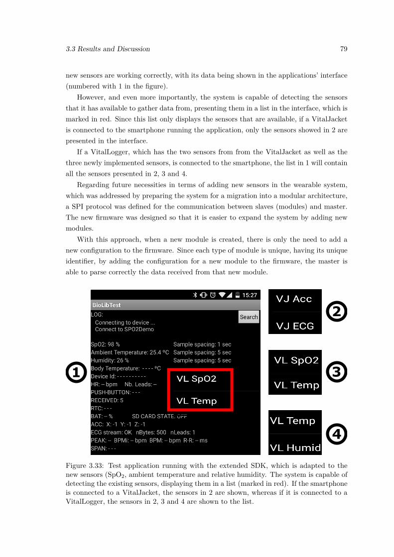
3.3 Results and Discussion 79
new sensors are working correctly, with its data being shown in the applications’ interface(numbered with 1 in the figure).
However, and even more importantly, the system is capable of detecting the sensorsthat it has available to gather data from, presenting them in a list in the interface, which ismarked in red. Since this list only displays the sensors that are available, if a VitalJacketis connected to the smartphone running the application, only the sensors showed in 2 arepresented in the interface.
If a VitalLogger, which has the two sensors from from the VitalJacket as well as thethree newly implemented sensors, is connected to the smartphone, the list in 1 will containall the sensors presented in 2, 3 and 4.
Regarding future necessities in terms of adding new sensors in the wearable system,which was addressed by preparing the system for a migration into a modular architecture,a SPI protocol was defined for the communication between slaves (modules) and master.The new firmware was designed so that it is easier to expand the system by adding newmodules.
With this approach, when a new module is created, there is only the need to add anew configuration to the firmware. Since each type of module is unique, having its uniqueidentifier, by adding the configuration for a new module to the firmware, the master isable to parse correctly the data received from that new module.
1
2
3
4
Figure 3.33: Test application running with the extended SDK, which is adapted to thenew sensors (SpO2, ambient temperature and relative humidity. The system is capable ofdetecting the existing sensors, displaying them in a list (marked in red). If the smartphoneis connected to a VitalJacket, the sensors in 2 are shown, whereas if it is connected to aVitalLogger, the sensors in 2, 3 and 4 are shown to the list.
80 VitalSensors - Towards a more intelligent, wearable monitoring system
Figure 3.34: SPI communication between a fictitious VitalLogger module (slave) and amaster. The sections of the datagram are aligned with the respective bytes in the MISOchannel. The second “data” segment corresponds to the ambient temperature data, whichis contained in two bytes of information.
During this work, the SPI protocol was implemented with a configuration for a Vital-Logger module, which might be created in the near future, that contains data from theSpO2, ambient temperature and relative humidity sensors.
The datagram for the SPI communication between this module and the master com-prises three data segments, which correspond to the data from the three sensors that thefictitious VitalLogger module possesses. Both the datagram and the SPI communicationitself, captured using Logic, are presented in Figure 3.34, with the datagram being alignedwith the respective bytes seen in MISO channel. The identifier for this module was setwith the number 1, as can be seen in Figure 3.34.
Also, while this module possesses three sensors, information for ambient temperaturehas to be represented using two bytes of information. This is because ambient temperaturemust be sent as an integer value. When the master receives the ambient temperature fromthe slave, its parser divides the value by 10, hence obtaining the temperature with aninteger and a float part. Therefore, the first byte after module ID contains SpO2 data, thesecond and third ones contain ambient temperature data, and the fourth byte containsthe measurement for relative humidity.
3.3.2 Intelligent Data Reduction
In order to select the best configuration (buffer size, delay and threshold) to implement inthe generic data reduction algorithm, the F1 score was computed for each delay.
Table 3.1 summarizes the highest F1 score obtained for each delay (from 1 to 9 samples,since delays higher that 9 showed worse performance in the ROC curve analysis), and italso has the threshold used to obtain the given F1 score. Moreover, Table 3.1 also contains
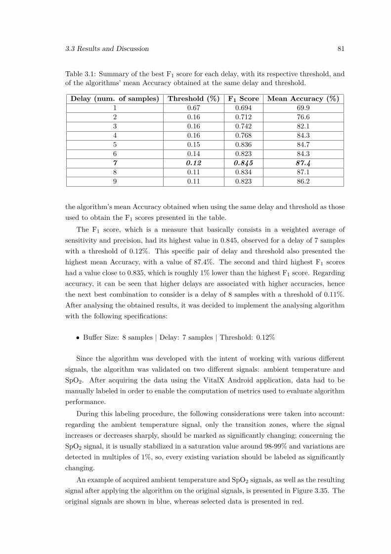
3.3 Results and Discussion 81
Table 3.1: Summary of the best F1 score for each delay, with its respective threshold, andof the algorithms’ mean Accuracy obtained at the same delay and threshold.
Delay (num. of samples) Threshold (%) F1 Score Mean Accuracy (%)1 0.67 0.694 69.92 0.16 0.712 76.63 0.16 0.742 82.14 0.16 0.768 84.35 0.15 0.836 84.76 0.14 0.823 84.37 0.12 0.845 87.48 0.11 0.834 87.19 0.11 0.823 86.2
the algorithm’s mean Accuracy obtained when using the same delay and threshold as thoseused to obtain the F1 scores presented in the table.
The F1 score, which is a measure that basically consists in a weighted average ofsensitivity and precision, had its highest value in 0.845, observed for a delay of 7 sampleswith a threshold of 0.12%. This specific pair of delay and threshold also presented thehighest mean Accuracy, with a value of 87.4%. The second and third highest F1 scoreshad a value close to 0.835, which is roughly 1% lower than the highest F1 score. Regardingaccuracy, it can be seen that higher delays are associated with higher accuracies, hencethe next best combination to consider is a delay of 8 samples with a threshold of 0.11%.After analysing the obtained results, it was decided to implement the analysing algorithmwith the following specifications:
• Buffer Size: 8 samples | Delay: 7 samples | Threshold: 0.12%
Since the algorithm was developed with the intent of working with various differentsignals, the algorithm was validated on two different signals: ambient temperature andSpO2. After acquiring the data using the VitalX Android application, data had to bemanually labeled in order to enable the computation of metrics used to evaluate algorithmperformance.
During this labeling procedure, the following considerations were taken into account:regarding the ambient temperature signal, only the transition zones, where the signalincreases or decreases sharply, should be marked as significantly changing; concerning theSpO2 signal, it is usually stabilized in a saturation value around 98-99% and variations aredetected in multiples of 1%, so, every existing variation should be labeled as significantlychanging.
An example of acquired ambient temperature and SpO2 signals, as well as the resultingsignal after applying the algorithm on the original signals, is presented in Figure 3.35. Theoriginal signals are shown in blue, whereas selected data is presented in red.
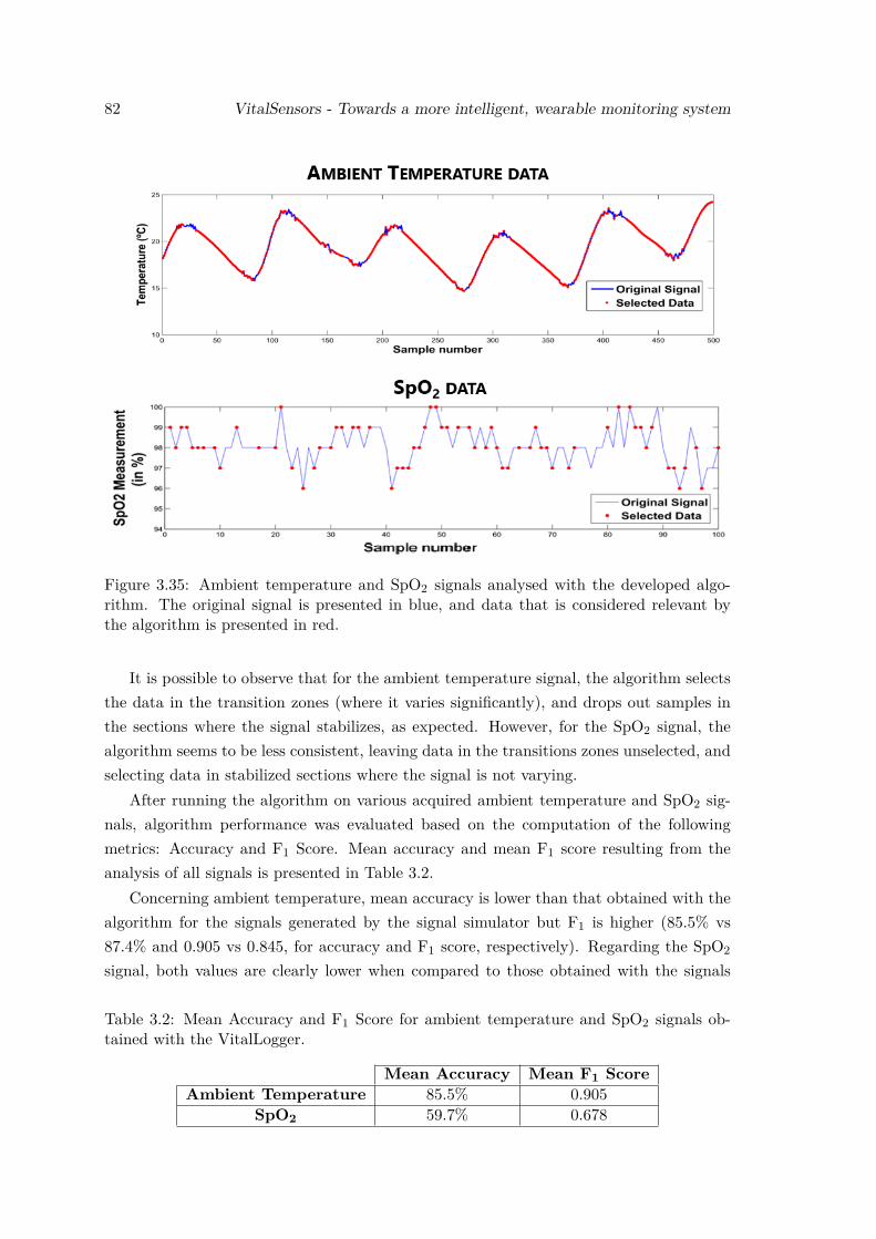
82 VitalSensors - Towards a more intelligent, wearable monitoring system
Figure 3.35: Ambient temperature and SpO2 signals analysed with the developed algo-rithm. The original signal is presented in blue, and data that is considered relevant bythe algorithm is presented in red.
It is possible to observe that for the ambient temperature signal, the algorithm selectsthe data in the transition zones (where it varies significantly), and drops out samples inthe sections where the signal stabilizes, as expected. However, for the SpO2 signal, thealgorithm seems to be less consistent, leaving data in the transitions zones unselected, andselecting data in stabilized sections where the signal is not varying.
After running the algorithm on various acquired ambient temperature and SpO2 sig-nals, algorithm performance was evaluated based on the computation of the followingmetrics: Accuracy and F1 Score. Mean accuracy and mean F1 score resulting from theanalysis of all signals is presented in Table 3.2.
Concerning ambient temperature, mean accuracy is lower than that obtained with thealgorithm for the signals generated by the signal simulator but F1 is higher (85.5% vs87.4% and 0.905 vs 0.845, for accuracy and F1 score, respectively). Regarding the SpO2
signal, both values are clearly lower when compared to those obtained with the signals
Table 3.2: Mean Accuracy and F1 Score for ambient temperature and SpO2 signals ob-tained with the VitalLogger.
Mean Accuracy Mean F1 ScoreAmbient Temperature 85.5% 0.905
SpO2 59.7% 0.678
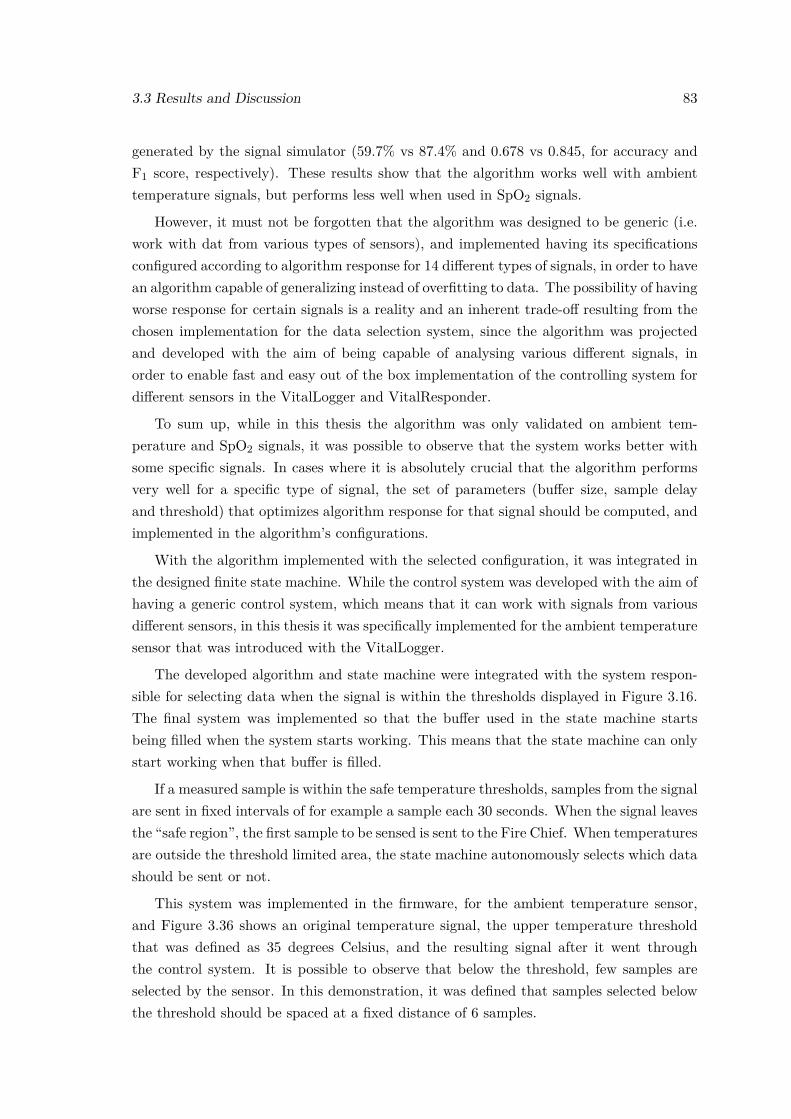
3.3 Results and Discussion 83
generated by the signal simulator (59.7% vs 87.4% and 0.678 vs 0.845, for accuracy andF1 score, respectively). These results show that the algorithm works well with ambienttemperature signals, but performs less well when used in SpO2 signals.
However, it must not be forgotten that the algorithm was designed to be generic (i.e.work with dat from various types of sensors), and implemented having its specificationsconfigured according to algorithm response for 14 different types of signals, in order to havean algorithm capable of generalizing instead of overfitting to data. The possibility of havingworse response for certain signals is a reality and an inherent trade-off resulting from thechosen implementation for the data selection system, since the algorithm was projectedand developed with the aim of being capable of analysing various different signals, inorder to enable fast and easy out of the box implementation of the controlling system fordifferent sensors in the VitalLogger and VitalResponder.
To sum up, while in this thesis the algorithm was only validated on ambient tem-perature and SpO2 signals, it was possible to observe that the system works better withsome specific signals. In cases where it is absolutely crucial that the algorithm performsvery well for a specific type of signal, the set of parameters (buffer size, sample delayand threshold) that optimizes algorithm response for that signal should be computed, andimplemented in the algorithm’s configurations.
With the algorithm implemented with the selected configuration, it was integrated inthe designed finite state machine. While the control system was developed with the aim ofhaving a generic control system, which means that it can work with signals from variousdifferent sensors, in this thesis it was specifically implemented for the ambient temperaturesensor that was introduced with the VitalLogger.
The developed algorithm and state machine were integrated with the system respon-sible for selecting data when the signal is within the thresholds displayed in Figure 3.16.The final system was implemented so that the buffer used in the state machine startsbeing filled when the system starts working. This means that the state machine can onlystart working when that buffer is filled.
If a measured sample is within the safe temperature thresholds, samples from the signalare sent in fixed intervals of for example a sample each 30 seconds. When the signal leavesthe “safe region”, the first sample to be sensed is sent to the Fire Chief. When temperaturesare outside the threshold limited area, the state machine autonomously selects which datashould be sent or not.
This system was implemented in the firmware, for the ambient temperature sensor,and Figure 3.36 shows an original temperature signal, the upper temperature thresholdthat was defined as 35 degrees Celsius, and the resulting signal after it went throughthe control system. It is possible to observe that below the threshold, few samples areselected by the sensor. In this demonstration, it was defined that samples selected belowthe threshold should be spaced at a fixed distance of 6 samples.
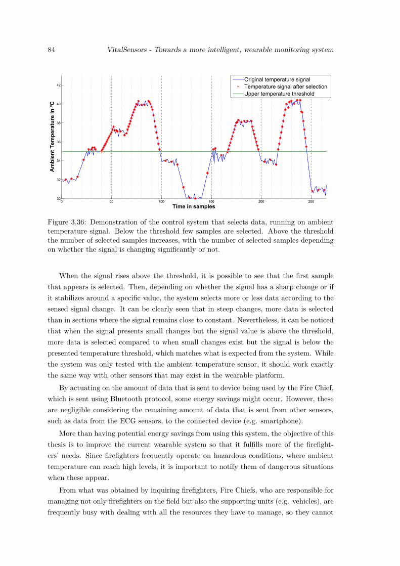
84 VitalSensors - Towards a more intelligent, wearable monitoring system
Figure 3.36: Demonstration of the control system that selects data, running on ambienttemperature signal. Below the threshold few samples are selected. Above the thresholdthe number of selected samples increases, with the number of selected samples dependingon whether the signal is changing significantly or not.
When the signal rises above the threshold, it is possible to see that the first samplethat appears is selected. Then, depending on whether the signal has a sharp change or ifit stabilizes around a specific value, the system selects more or less data according to thesensed signal change. It can be clearly seen that in steep changes, more data is selectedthan in sections where the signal remains close to constant. Nevertheless, it can be noticedthat when the signal presents small changes but the signal value is above the threshold,more data is selected compared to when small changes exist but the signal is below thepresented temperature threshold, which matches what is expected from the system. Whilethe system was only tested with the ambient temperature sensor, it should work exactlythe same way with other sensors that may exist in the wearable platform.
By actuating on the amount of data that is sent to device being used by the Fire Chief,which is sent using Bluetooth protocol, some energy savings might occur. However, theseare negligible considering the remaining amount of data that is sent from other sensors,such as data from the ECG sensors, to the connected device (e.g. smartphone).
More than having potential energy savings from using this system, the objective of thisthesis is to improve the current wearable system so that it fulfills more of the firefight-ers’ needs. Since firefighters frequently operate on hazardous conditions, where ambienttemperature can reach high levels, it is important to notify them of dangerous situationswhen these appear.
From what was obtained by inquiring firefighters, Fire Chiefs, who are responsible formanaging not only firefighters on the field but also the supporting units (e.g. vehicles), arefrequently busy with dealing with all the resources they have to manage, so they cannot
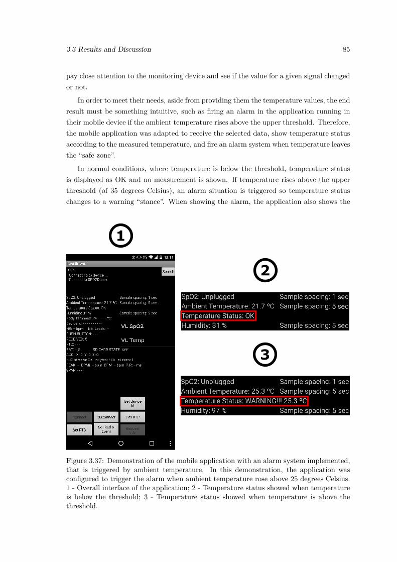
3.3 Results and Discussion 85
pay close attention to the monitoring device and see if the value for a given signal changedor not.
In order to meet their needs, aside from providing them the temperature values, the endresult must be something intuitive, such as firing an alarm in the application running intheir mobile device if the ambient temperature rises above the upper threshold. Therefore,the mobile application was adapted to receive the selected data, show temperature statusaccording to the measured temperature, and fire an alarm system when temperature leavesthe “safe zone”.
In normal conditions, where temperature is below the threshold, temperature statusis displayed as OK and no measurement is shown. If temperature rises above the upperthreshold (of 35 degrees Celsius), an alarm situation is triggered so temperature statuschanges to a warning “stance”. When showing the alarm, the application also shows the
1
Figure 3.37: Demonstration of the mobile application with an alarm system implemented,that is triggered by ambient temperature. In this demonstration, the application wasconfigured to trigger the alarm when ambient temperature rose above 25 degrees Celsius.1 - Overall interface of the application; 2 - Temperature status showed when temperatureis below the threshold; 3 - Temperature status showed when temperature is above thethreshold.
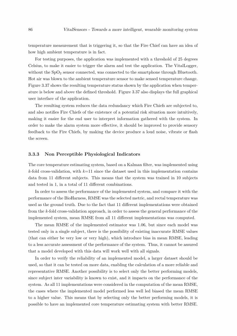
86 VitalSensors - Towards a more intelligent, wearable monitoring system
temperature measurement that is triggering it, so that the Fire Chief can have an idea ofhow high ambient temperature is in fact.
For testing purposes, the application was implemented with a threshold of 25 degreesCelsius, to make it easier to trigger the alarm and test the application. The VitalLogger,without the SpO2 sensor connected, was connected to the smartphone through Bluetooth.Hot air was blown to the ambient temperature sensor to make sensed temperature change.Figure 3.37 shows the resulting temperature status shown by the application when temper-ature is below and above the defined threshold. Figure 3.37 also displays the full graphicaluser interface of the application.
The resulting system reduces the data redundancy which Fire Chiefs are subjected to,and also notifies Fire Chiefs of the existence of a potential risk situation more intuitively,making it easier for the end user to interpret information gathered with the system. Inorder to make the alarm system more effective, it should be improved to provide sensoryfeedback to the Fire Chiefs, by making the device produce a loud noise, vibrate or flashthe screen.
3.3.3 Non Perceptible Physiological Indicators
The core temperature estimating system, based on a Kalman filter, was implemented usingk-fold cross-validation, with k=11 since the dataset used in this implementation containsdata from 11 different subjects. This means that the system was trained in 10 subjectsand tested in 1, in a total of 11 different combinations.
In order to assess the performance of the implemented system, and compare it with theperformance of the BioHarness, RMSE was the selected metric, and rectal temperature wasused as the ground truth. Due to the fact that 11 different implementations were obtainedfrom the k-fold cross-validation approach, in order to assess the general performance of theimplemented system, mean RMSE from all 11 different implementations was computed.
The mean RMSE of the implemented estimator was 1.06, but since each model wastested only in a single subject, there is the possibility of existing inaccurate RMSE values(that can either be very low or very high), which introduce bias in mean RMSE, leadingto a less accurate assessment of the performance of the system. Thus, it cannot be assuredthat a model developed with this data will work well with all signals.
In order to verify the reliability of an implemented model, a larger dataset should beused, so that it can be tested on more data, enabling the calculation of a more reliable andrepresentative RMSE. Another possibility is to select only the better performing models,since subject inter variability is known to exist, and it impacts on the performance of thesystem. As all 11 implementations were considered in the computation of the mean RMSE,the cases where the implemented model performed less well led biased the mean RMSEto a higher value. This means that by selecting only the better performing models, it ispossible to have an implemented core temperature estimating system with better RMSE.
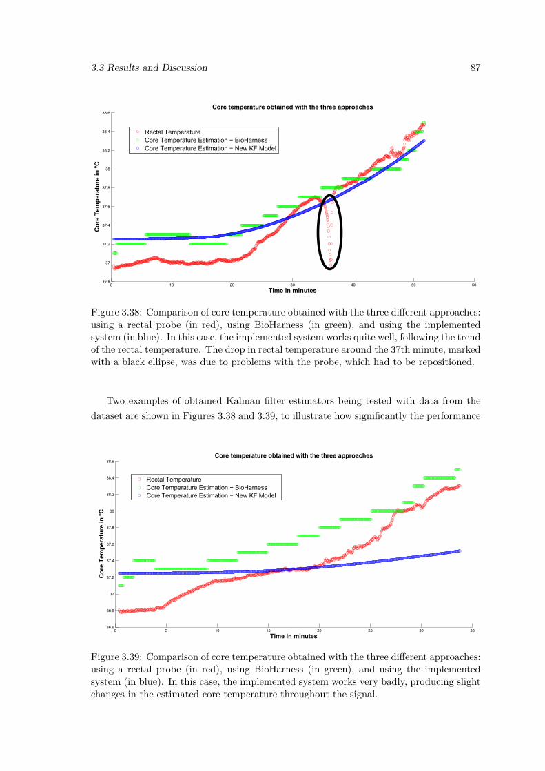
3.3 Results and Discussion 87
Figure 3.38: Comparison of core temperature obtained with the three different approaches:using a rectal probe (in red), using BioHarness (in green), and using the implementedsystem (in blue). In this case, the implemented system works quite well, following the trendof the rectal temperature. The drop in rectal temperature around the 37th minute, markedwith a black ellipse, was due to problems with the probe, which had to be repositioned.
Two examples of obtained Kalman filter estimators being tested with data from thedataset are shown in Figures 3.38 and 3.39, to illustrate how significantly the performance
Figure 3.39: Comparison of core temperature obtained with the three different approaches:using a rectal probe (in red), using BioHarness (in green), and using the implementedsystem (in blue). In this case, the implemented system works very badly, producing slightchanges in the estimated core temperature throughout the signal.
88 VitalSensors - Towards a more intelligent, wearable monitoring system
of the models can vary. In Figure 3.38, a relatively good estimator was obtained, withits estimations following those of BioHarness closely, and accompanying the trend of therectal temperature signal. Similarly to BioHarness estimations, the implemented systemseems to struggle in the stabilization phase of the signal, where rectal temperature is 0.2◦Clower than the estimated core temperature. Nonetheless, when in exercise conditions, thesystem seems to perform well. The drop in rectal temperature around the 37th minutewas due to problems with the probe, which had to be repositioned during the acquisition.
On the other hand, in Figure 3.39, it is easily observable that the implemented model isperforming very poorly, with obtained estimations of core temperature being just slightlychanged throughout the whole signal. This serves to demonstrate that the Kalman filtercan perform both very well and very badly, thus, in order to have a more reliable imple-mented system, that performs better, a larger dataset with data from the active settingshould be used, or only the better performing models should be selected.
Moreover, the performance of the implemented Kalman filter estimator was comparedagainst that of the system implemented in BioHarness, also using RMSE as the selectedmetric. This is possible as both BioHarness and the implemented estimator have coretemperature as the predicted variable. BioHarness’ RMSE was computed for all subjectsin the active setting dataset, with the mean RMSE being computed in the end.
As expected, ZephyrTM’s system performs better, having a mean RMSE of 0.70, com-pared to the mean RMSE of 1.06 obtained with the implemented system. However, it hasbeen shown in practical cases of Figure 3.38 and 3.39 that the implemented estimator cangreatly vary depending on the data it is developed and tested on.
Therefore, while the mean RMSE from the implemented system is lower than thatobtained by BioHarness, if only the better performing models (from the implementedsystem) are taken into account, it possible to have an implemented system with a lowerRMSE that is comparable to that of BioHarness, with its value standing around 0.8.
With the heart rate measurements from BioHarness, and with the core temperatureestimations from BioHarness and from the implemented predictor, PSI was then computedand compared for both systems, using RMSE as the evaluation metric.
In Figure 3.40, PSI was computed for a case where core temperature estimates wereclose to the real core temperature (rectal temperature). It is visible that PSI values remainclose together throughout most of the signal, with PSI computed using CT estimates fromthe implemented core temperature estimator being overestimated in the upper range of PSIvalues, having a maximum PSI value of 7. It can also be seen that PSI values computedwith core temperatures from the rectal probe and from BioHarness are very close toeach other (with a maximum PSI of 6.2), which shows that BioHarness is a reliable coretemperature estimator, as demonstrated in [78].
In Figure 3.41, PSI was computed for a case where core temperature estimates wereless accurate. Here, PSI was overestimated for temperatures from both core temperatureestimators. However, BioHarness’ PSI is overestimated with a relatively constant offset
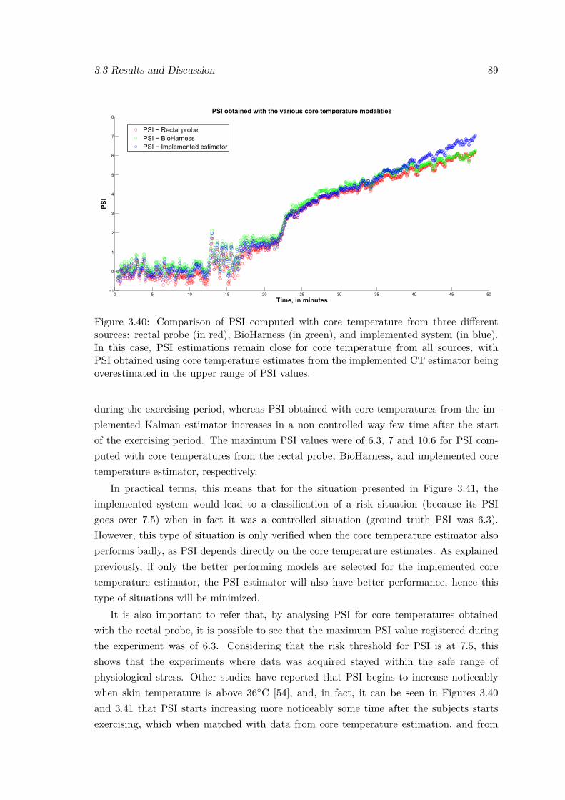
3.3 Results and Discussion 89
Figure 3.40: Comparison of PSI computed with core temperature from three differentsources: rectal probe (in red), BioHarness (in green), and implemented system (in blue).In this case, PSI estimations remain close for core temperature from all sources, withPSI obtained using core temperature estimates from the implemented CT estimator beingoverestimated in the upper range of PSI values.
during the exercising period, whereas PSI obtained with core temperatures from the im-plemented Kalman estimator increases in a non controlled way few time after the startof the exercising period. The maximum PSI values were of 6.3, 7 and 10.6 for PSI com-puted with core temperatures from the rectal probe, BioHarness, and implemented coretemperature estimator, respectively.
In practical terms, this means that for the situation presented in Figure 3.41, theimplemented system would lead to a classification of a risk situation (because its PSIgoes over 7.5) when in fact it was a controlled situation (ground truth PSI was 6.3).However, this type of situation is only verified when the core temperature estimator alsoperforms badly, as PSI depends directly on the core temperature estimates. As explainedpreviously, if only the better performing models are selected for the implemented coretemperature estimator, the PSI estimator will also have better performance, hence thistype of situations will be minimized.
It is also important to refer that, by analysing PSI for core temperatures obtainedwith the rectal probe, it is possible to see that the maximum PSI value registered duringthe experiment was of 6.3. Considering that the risk threshold for PSI is at 7.5, thisshows that the experiments where data was acquired stayed within the safe range ofphysiological stress. Other studies have reported that PSI begins to increase noticeablywhen skin temperature is above 36◦C [54], and, in fact, it can be seen in Figures 3.40and 3.41 that PSI starts increasing more noticeably some time after the subjects startsexercising, which when matched with data from core temperature estimation, and from
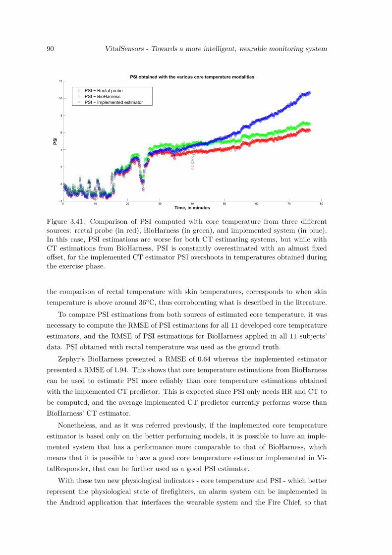
90 VitalSensors - Towards a more intelligent, wearable monitoring system
Figure 3.41: Comparison of PSI computed with core temperature from three differentsources: rectal probe (in red), BioHarness (in green), and implemented system (in blue).In this case, PSI estimations are worse for both CT estimating systems, but while withCT estimations from BioHarness, PSI is constantly overestimated with an almost fixedoffset, for the implemented CT estimator PSI overshoots in temperatures obtained duringthe exercise phase.
the comparison of rectal temperature with skin temperatures, corresponds to when skintemperature is above around 36◦C, thus corroborating what is described in the literature.
To compare PSI estimations from both sources of estimated core temperature, it wasnecessary to compute the RMSE of PSI estimations for all 11 developed core temperatureestimators, and the RMSE of PSI estimations for BioHarness applied in all 11 subjects’data. PSI obtained with rectal temperature was used as the ground truth.
Zephyr’s BioHarness presented a RMSE of 0.64 whereas the implemented estimatorpresented a RMSE of 1.94. This shows that core temperature estimations from BioHarnesscan be used to estimate PSI more reliably than core temperature estimations obtainedwith the implemented CT predictor. This is expected since PSI only needs HR and CT tobe computed, and the average implemented CT predictor currently performs worse thanBioHarness’ CT estimator.
Nonetheless, and as it was referred previously, if the implemented core temperatureestimator is based only on the better performing models, it is possible to have an imple-mented system that has a performance more comparable to that of BioHarness, whichmeans that it is possible to have a good core temperature estimator implemented in Vi-talResponder, that can be further used as a good PSI estimator.
With these two new physiological indicators - core temperature and PSI - which betterrepresent the physiological state of firefighters, an alarm system can be implemented inthe Android application that interfaces the wearable system and the Fire Chief, so that

3.3 Results and Discussion 91
this relevant physiological information can be provided in an intuitive and practical wayto the Fire Chiefs, hopefully contributing to make firefighters’ job more secure.

Chapter 4
Conclusions and Future Work
While wearable health systems are a promising and attractive market, most of its ap-plications are focused on medical applications, and more recently on sports and fitness.Nevertheless, the versatility of wearable health systems enables their adaptation to differ-ent target markets. This Master thesis focused on improving an existing wearable healthsystem that is centered on first responders, by providing not only more but better in-formation to first responders. In order to accomplish this objective, a workflow of threedifferent steps was elaborated to address different issues of the system. While it was man-aged to complete some of the projected objectives, others were only partially fulfilled. Inthe following lines the status of the objectives of each step will be summed up, and someindications for future work will be provided.
The first step regarded providing more information to first responders, by increasingthe number of sensors available in the wearable system. This objective was successfullycompleted with the adaptation of existing high-level firmware and SDK from VitalJacketto VitalLogger, a prototype wearable health system that expands the sensing capabilitiesof VitalJacket by adding a SpO2, ambient temperature and humidity sensor. This systemcan be integrated in VitalResponder, increasing the amount of data it can provide to firstresponders.
However, since there might be other sensing needs in the future that require the addi-tion of more sensors, VitalLogger’s firmware was prepared for a migration into a modulararchitecture. Here, a SPI protocol was successfully designed and implemented for thecommunication between master and slaves, but since there are currently no modules avail-able, the protocol was tested in a simulated hardware set using development boards. Thesystem is prepared so that configurations for new modules to be developed only need to beintroduced in the master’s parsing state machine, in order for the master to know how tocorrectly handle data received from each slave. In order to further improve the system, thecapability of turning sensors from the modules on and off when needed is an interestingnew feature to add.
Regarding the second step, which addressed the issue of selecting only relevant in-
93
94 Conclusions and Future Work
formation from acquired data, and conveying it in an intuitive way to the Fire Chief,the projected objectives were also completed by creating a system that is capable of au-tonomously selecting the relevant data in a sensed signal, and also through the creation ofan alarm system that informs that Fire Chief about the safety status of ambient temper-ature. However, there are several improvements that can be made to the system. Firstly,new parameter specifications for the data selection algorithm can be obtained by devel-oping the algorithm on a more complete signal simulator. Not only that, but specificconfigurations can be developed for different types of signal (SpO2, ambient temperature,etc) and added to the system as presets that can be easily selected during implementationin the firmware. This will ensure that the data selecting system performs well for thevarious different types of signals.
Another interesting aspect for future work is to develop the data selecting systemwith other metrics, such as signal variance, which might be more effective in the selectingprocess. These new metrics must be analysed along with the available hardware resources,as a metric like signal variance might require a larger buffer size in order to work properly.
Lastly, and regarding the communication of selected information in an intuitive way tothe Fire Chiefs, the alarm system for signals such as ambient temperature can be improvedto provide sensory feedback (vibrate, produce a loud noise, flash) to the Fire Chiefs whenin the presence of a dangerous situation. This feature is very important as with all thechaos that exists in the field, sensory feedback has the potential to alert the Fire Chiefmore effectively.
Finally, in what regards the third step, which addressed the issue of providing rel-evant physiological information from first responders that cannot be measured directlywith sensors, the defined objectives were only partially completed. The first part, whichcomprised getting access to a database with different sensing modalities (rectal and skintemperature, heat flux and heart rate), and assembling a dataset with that informationwas successfully completed. Since the assembled dataset contains various sensing modal-ities for different experimental conditions, it can be useful, in the future, for other worksthat are not directly related to the core temperature estimator.
The second part involved developing a core temperature estimator with a performancesimilar to that of an existing system in the market, which is the BioHarness. This ob-jective was partially completed as the obtained estimator must still be improved beforeimplementing in the VitalResponder. Future work to improve the first version of the es-timator can involve improving the estimation of certain parameters of the Kalman filter,namely the mapping matrix Hk.
With a robust estimator that uses only heart rate measurements to estimate core tem-perature, it is possible to compute PSI values, which can be implemented in an alarmsystem. Similarly to what was suggested in the second step, this alarm system shouldprovide sensory feedback (e.g. producing a loud sound) in case of an existing risk sit-uation. Finally, the estimator can be improved even further, by adding data from skin
Conclusions and Future Work 95
temperature sensors to increase the accuracy of the core temperature estimations, whichwill consequently improve the accuracy of computed PSI values, while reducing the biasin PSI resultant from heart rate measurements.
Work developed during this thesis had the objective of moving towards a more com-plete wearable sensing system. The improvements made with this work were projectedwith the intent of matching the specific needs of first responders. Nevertheless, since thewearable solution and technology from Biodevices SA is versatile, the newly implementedfeatures can be exploited for different uses and target markets. Moreover, it is hopedthat after implementing the suggested improvements, specially regarding the core temper-ature estimator, the resulting work from this thesis can help Biodevices SA expanding itssolutions.

References
[1] D. Curone, E. L. Secco, A. Tognetti, G. Loriga, G. Dudnik, M. Risatti, R. Whyte,A. Bonfiglio, and G. Magenes, “Smart garments for emergency operators: theproeTEX project,” IEEE Trans Inf Technol Biomed, vol. 14, no. 3, pp. 694–701,2010. [Online]. Available: http://www.ncbi.nlm.nih.gov/pubmed/20371413
[2] “Know thyself: Tracking every facet of life, from sleep to mood to pain, 24/7/365,”June 2009 2009. [Online]. Available: http://archive.wired.com/medtech/health/magazine/17-07/lbnp_knowthyself?currentPage=all
[3] A. Lymberis and L. Gatzoulis, “Wearable health systems: from smart technologiesto real applications,” Conf Proc IEEE Eng Med Biol Soc, vol. Suppl, pp. 6789–92,2006. [Online]. Available: http://www.ncbi.nlm.nih.gov/pubmed/17959513
[4] J. P. Cunha, “pHealth and wearable technologies: a permanent challenge,”Stud Health Technol Inform, vol. 177, pp. 185–95, 2012. [Online]. Available:http://www.ncbi.nlm.nih.gov/pubmed/22942053
[5] P. Lukowicz, T. Kirstein, and G. Troster, “Wearable systems for health careapplications,” Methods Inf Med, vol. 43, no. 3, pp. 232–8, 2004. [Online]. Available:http://www.ncbi.nlm.nih.gov/pubmed/15227552
[6] C. C. Poon and Y. T. Zhang, “Perspectives on high technologies for low-costhealthcare,” IEEE Eng Med Biol Mag, vol. 27, no. 5, pp. 42–7, 2008. [Online].Available: http://www.ncbi.nlm.nih.gov/pubmed/18799389
[7] R. Paradiso, G. Loriga, and N. Taccini, “A wearable health care system basedon knitted integrated sensors,” IEEE Transactions on Information Technology inBiomedicine, vol. 9, no. 3, pp. 337–344, 2009.
[8] S. Tennina, M. Di Renzo, E. Kartsakli, F. Graziosi, A. S. Lalos, A. Antonopoulos,P. V. Mekikis, and L. Alonso, “WSN4QoL: A WSN-oriented healthcare systemarchitecture,” International Journal of Distributed Sensor Networks, 2014. [Online].Available: <GotoISI>://WOS:000336172300001
[9] A. Asensio, A. Marco, R. Blasco, and R. Casas, “Protocol and architecture to bringthings into internet of things,” International Journal of Distributed Sensor Networks,2014. [Online]. Available: <GotoISI>://WOS:000335325200001
[10] X. F. Teng, Y. T. Zhang, C. C. Poon, and P. Bonato, “Wearable medical systemsfor p-Health,” IEEE Rev Biomed Eng, vol. 1, pp. 62–74, 2008. [Online]. Available:http://www.ncbi.nlm.nih.gov/pubmed/22274900
97
98 REFERENCES
[11] Z. A. Khan, S. Sivakumar, W. Phillips, and B. Robertson, “ZEQoS: A new energyand QoS-aware routing protocol for communication of sensor devices in healthcaresystem,” International Journal of Distributed Sensor Networks, 2014. [Online].Available: <GotoISI>://WOS:000337435500001
[12] H. B. Lim, D. Ma, B. Wang, Z. Kalbarczyk, R. Iyer, and K. Watkin, “A soldier healthmonitoring system for military applications,” in Body Sensor Networks (BSN), 2010International Conference on, June 2010, pp. 246–249.
[13] H. Y. Xu, L. Y. Wang, and H. Xie, “Design and experiment analysis ofa hadoop-based video transcoding system for next-generation wireless sensornetworks,” International Journal of Distributed Sensor Networks, 2014. [Online].Available: <GotoISI>://WOS:000333838200001
[14] “Cooperative communication.” [Online]. Available: http://wcomm.ulsan.ac.kr/research/research.htm
[15] “ZigBee R© wireless standard.” [Online]. Available: http://www.digi.com/technology/rf-articles/wireless-zigbee
[16] “Wireless connectivity - overview for ZigBee R© (IEEE 802.15.4).” [Online].Available: http://www.ti.com/lsds/ti/wireless_connectivity/zigbee/overview.page?DCMP=hpa_rf_general&HQS=NotApplicable+OT+zigbee
[17] “What is ZigBee?” [Online]. Available: http://zigbee.org/what-is-zigbee/
[18] G. Appelboom, E. Camacho, M. E. Abraham, S. S. Bruce, E. L. Dumont,B. E. Zacharia, R. D’Amico, J. Slomian, J. Y. Reginster, O. Bruyere, andJ. Connolly, E. S., “Smart wearable body sensors for patient self-assessment andmonitoring,” Arch Public Health, vol. 72, no. 1, p. 28, 2014. [Online]. Available:http://www.ncbi.nlm.nih.gov/pubmed/25232478
[19] F. Seoane, I. Mohino-Herranz, J. Ferreira, L. Alvarez, R. Buendia, D. Ayllon,C. Llerena, and R. Gil-Pita, “Wearable biomedical measurement systems forassessment of mental stress of combatants in real time,” Sensors (Basel), vol. 14,no. 4, pp. 7120–41, 2014. [Online]. Available: http://www.ncbi.nlm.nih.gov/pubmed/24759113
[20] A. B. Farjadian, M. L. Sivak, and C. Mavroidis, “SQUID: sensorized shirtwith smartphone interface for exercise monitoring and home rehabilitation,”IEEE Int Conf Rehabil Robot, vol. 2013, p. 6650451, 2013. [Online]. Available:http://www.ncbi.nlm.nih.gov/pubmed/24187268
[21] “EQ02 LifeMonitor - sensor electronics module (SEM).” [Online]. Avail-able: http://www.equivital.co.uk/assets/common/SEM_Data_Sheet_General_HIDA3330-DSG-02.2_.2_.pdf
[22] “BioHarness 3 - wireless professional heart rate monitor & physiological monitor withbluetooth.” [Online]. Available: http://zephyranywhere.com/products/bioharness-3/
[23] “BioPatchTM wireless device.” [Online]. Available: http://zephyranywhere.com/products/biopatch/
REFERENCES 99
[24] “First Responders - Zephyr Technology Corporation.” [Online]. Available: http://www.zephyranywhere.com/training-systems/first-responders
[25] “WASP: Wearable Advanced Sensor Platform.” [Online]. Available: http://www.globeturnoutgear.com/innovations/wasp
[26] “WASPTM - Wearable Advanced Sensor Platform - brochure.” [Online]. Avail-able: http://www.globeturnoutgear.com/uploads/PDFs/Globe_Catalog_WASP_System.pdf
[27] “ProeTEX partners.” [Online]. Available: http://www.proetex.org/partners.htm
[28] E. L. Secco, D. Curone, A. Tognetti, A. Bonfiglio, and G. Magenes, “Validation ofsmart garments for physiological and activity-related monitoring of humans in harshenvironment,” AMERICAN JOURNAL OF BIOMEDICAL ENGINEERING, vol. 2,2012. [Online]. Available: http://dx.medra.org/10.5923/j.ajbe.20120204.07
[29] C. Hertleer, S. Odhiambo, and L. Van Langenhove, 12 - Protective clothing forfirefighters and rescue workers. Woodhead Publishing, 2013, pp. 338–363. [Online].Available: http://www.sciencedirect.com/science/article/pii/B9780857090560500121
[30] M. R. Roberts, “Watch and wear - globe turnout gear,” January 2013 2013. [Online].Available: http://goo.gl/gcnZcJ
[31] “What is P25 technology?” [Online]. Available: http://www.project25.org/technology
[32] Tehrani, Kiana, and A. Michael, “Wearable technology and wearable devices:Everything you need to know,” March 26, 2014. [Online]. Available: http://www.wearabledevices.com/what-is-a-wearable-device/
[33] “Wearable device market value from 2010 to 2018 (in million u.s. dol-lars),” May 2013. [Online]. Available: http://www.statista.com/statistics/259372/wearable-device-market-value/
[34] M. Boustany and J. Bouchaud, “MEMS & sensors for wearables report -2014,” September 30, 2014. [Online]. Available: https://technology.ihs.com/496122/mems-sensors-for-wearables-2014
[35] V. Yussuff, “Apple watch spurs rapid growth of market for wireless chargingin wearable technology in 2015,” January 15, 2015. [Online]. Available:http://goo.gl/l65t08
[36] A. Michael, “Morgan stanley: Wearable devices a potential $1.6 trillion business,”November 20, 2014. [Online]. Available: http://www.wearabledevices.com/2014/11/20/morgan-stanley-wearable-devices/
[37] J. Bouchaud, “Wearable sensor market to expand sevenfold in five years,”October 16, 2014. [Online]. Available: https://technology.ihs.com/513647/wearable-sensor-market-to-expand-sevenfold-in-five-years
[38] “Wearable technology application chart.” [Online]. Available: http://www.beechamresearch.com/article.aspx?id=20
100 REFERENCES
[39] V. Yussuff, “Wireless charging in wearable technology report - 2015,”December 19, 2014. [Online]. Available: https://technology.ihs.com/518744/wireless-charging-in-wearable-technology-2015
[40] E. Markowitz, “How the department of homeland securityis tapping silicon valley for futuristic first-responder gear,”November 2015. [Online]. Available: http://www.ibtimes.com/how-department-homeland-security-tapping-silicon-valley-futuristic-first-responder-2111288
[41] M. Elliott and A. Coventry, “Critical care: the eight vital signs of patientmonitoring,” Br J Nurs, vol. 21, no. 10, pp. 621–5, 2012. [Online]. Available:http://www.ncbi.nlm.nih.gov/pubmed/22875303
[42] A. J. Bandodkar and J. Wang, “Non-invasive wearable electrochemical sensors: areview,” Trends Biotechnol, vol. 32, no. 7, pp. 363–71, 2014. [Online]. Available:http://www.ncbi.nlm.nih.gov/pubmed/24853270
[43] G. Tröster, “The Agenda of Wearable Healthcare,” IMIA Yearbook of Medical Infor-matics 2005: Ubiquitous Health Care Systems, pp. 125–38, 2005.
[44] Y. M. Chi, J. Tzyy-Ping, and G. Cauwenberghs, “Dry-contact and noncontact biopo-tential electrodes: Methodological review,” Biomedical Engineering, IEEE Reviewsin, vol. 3, pp. 106–119, 2010.
[45] J. A. G. Gnecchi, A. D. V. Herrejon, A. D. T. Anguiano, A. M. Patino, andD. L. Espinoza, “Advances in the construction of ECG wearable sensor technology:The ECG-ITM-05 eHealth data acquisition system,” 2012 Ieee Ninth Electronics,Robotics and Automotive Mechanics Conference (Cerma 2012), pp. 338–342, 2012.[Online]. Available: <GotoISI>://WOS:000324574000057
[46] A. D. Droitcour, O. Boric-Lubecke, V. M. Lubecke, J. S. Lin, and G. T. A.Kovacs, “Range correlation and I/Q performance benefits in single-chip silicondoppler radars for noncontact cardiopulmonary monitoring,” Ieee Transactionson Microwave Theory and Techniques, vol. 52, no. 3, pp. 838–848, 2004.[Online]. Available: <GotoISI>://WOS:000220177500013http://ieeexplore.ieee.org/xpl/articleDetails.jsp?arnumber=1273725
[47] A. Sa-ngasoongsong, J. Kunthong, V. Sarangan, X. Cai, and S. T. S. Bukkapatnam,“A low-cost, portable, high-throughput wireless sensor system for phonocardiographyapplications,” Sensors, vol. 12, no. 8, pp. 10 851–10 870, 2012. [Online]. Available:http://www.mdpi.com/1424-8220/12/8/10851
[48] Y. P. Hsu and D. J. Young, “Skin-coupled personal wearable ambulatorypulse wave velocity monitoring system using microelectromechanical sensors,”Ieee Sensors Journal, vol. 14, no. 10, pp. 3490–3497, 2014. [Online]. Available:<GotoISI>://WOS:000341629100004
[49] J. Franco, J. Aedo, and F. Rivera, “Continuous, non-invasive and cuff-free bloodpressure monitoring system,” 2012 Andean Region International Conference, pp. 31–34, 2012.
<Go to ISI>://WOS:000220177500013 http://ieeexplore.ieee.org/xpl/articleDetails.jsp?arnumber=1273725
REFERENCES 101
[50] S. Fuke, T. Suzuki, K. Nakayama, H. Tanaka, and S. Minami, “Bloodpressure estimation from pulse wave velocity measured on the chest,” Conf ProcIEEE Eng Med Biol Soc, vol. 2013, pp. 6107–10, 2013. [Online]. Available:http://www.ncbi.nlm.nih.gov/pubmed/24111133
[51] L. Guo, L. Berglin, U. Wiklund, and H. Mattila, “Design of a garment-based sensingsystem for breathing monitoring,” Textile Research Journal, vol. 83, no. 5, pp. 499–509, 2012.
[52] J. Sola, S. Castoldi, O. Chetelat, M. Correvon, S. Dasen, S. Droz, N. Jacob,R. Kormann, V. Neumann, A. Perrenoud, P. Pilloud, C. Verjus, and G. Viardot,“SpO2 sensor embedded in a finger ring: design and implementation,” ConfProc IEEE Eng Med Biol Soc, vol. 1, pp. 4295–8, 2006. [Online]. Available:http://www.ncbi.nlm.nih.gov/pubmed/17946619
[53] C. Zysset, N. Nasseri, L. Buthe, N. Munzenrieder, T. Kinkeldei, L. Petti, S. Kleiser,G. A. Salvatore, M. Wolf, and G. Troster, “Textile integrated sensors and actuatorsfor near-infrared spectroscopy,” Opt Express, vol. 21, no. 3, pp. 3213–24, 2013.[Online]. Available: http://www.ncbi.nlm.nih.gov/pubmed/23481780
[54] E. Gaura, J. Kemp, and J. Brusey, “Leveraging knowledge from physiological data:On-body heat stress risk prediction with sensor networks,” Biomedical Circuits andSystems, IEEE Transactions on, vol. 7, no. 6, pp. 861–870, Dec 2013.
[55] M. J. Buller, W. J. Tharion, R. W. Hoyt, and O. C. Jenkins, “Estimation of humaninternal temperature from wearable physiological sensors.” in Innovative Applicationsof Artificial Intelligence Conference, 2010, Conference Proceedings.
[56] M. J. Buller, W. J. Tharion, S. N. Cheuvront, S. J. Montain, R. W. Kenefick,J. Castellani, W. A. Latzka, W. S. Roberts, M. Richter, O. C. Jenkins, andR. W. Hoyt, “Estimation of human core temperature from sequential heart rateobservations,” Physiological Measurement, vol. 34, no. 7, p. 781, 2013. [Online].Available: http://stacks.iop.org/0967-3334/34/i=7/a=781
[57] M. N. Sawka and A. J. Young, Chapter 23 - Physiological Systems and Their Re-sponses to Conditions of Heat and Cold. Lippincott Williams & Wilkins, 2006.
[58] Z. Popovic, P. Momenroodaki, and R. Scheeler, “Toward wearable wirelessthermometers for internal body temperature measurements,” Ieee CommunicationsMagazine, vol. 52, no. 10, pp. 118–125, 2014. [Online]. Available: <GotoISI>://WOS:000346036300018
[59] C. Boano, M. Lasagni, K. Romer, and T. Lange, “Accurate tempera-ture measurements for medical research using body sensor networks,” inObject/Component/Service-Oriented Real-Time Distributed Computing Workshops(ISORCW), 2011 14th IEEE International Symposium on, March 2011, pp. 189–198.
[60] R. C. Webb, A. P. Bonifas, A. Behnaz, Y. Zhang, K. J. Yu, H. Cheng, M. Shi,Z. Bian, Z. Liu, Y. S. Kim, W. H. Yeo, J. S. Park, J. Song, Y. Li, Y. Huang, A. M.Gorbach, and J. A. Rogers, “Ultrathin conformal devices for precise and continuousthermal characterization of human skin,” Nat Mater, vol. 12, no. 10, pp. 938–44,2013. [Online]. Available: http://www.ncbi.nlm.nih.gov/pubmed/24037122
102 REFERENCES
[61] X. Xu, A. J. Karis, M. J. Buller, and W. R. Santee, “Relationship between coretemperature, skin temperature, and heat flux during exercise in heat,” EuropeanJournal of Applied Physiology, vol. 113, no. 9, pp. 2381–2389, 2013. [Online].Available: http://dx.doi.org/10.1007/s00421-013-2674-z
[62] D. S. Moran, A. Shitzer, and K. B. Pandolf, “A physiological strain index to evaluateheat stress,” American Journal of Physiology - Regulatory, Integrative and Compar-ative Physiology, vol. 275, no. 1, pp. R129–R134, 1998.
[63] M. J. Buller, W. A. Latzka, M. Yokota, W. J. Tharion, and D. S. Moran,“A real-time heat strain risk classifier using heart rate and skin temperature,”Physiological Measurement, vol. 29, no. 12, p. N79, 2008. [Online]. Available:http://stacks.iop.org/0967-3334/29/i=12/a=N01
[64] J. P. S. Cunha, B. Cunha, A. S. Pereira, W. Xavier, N. Ferreira, and L. Meireles,“Vital-Jacket R©: A wearable wireless vital signs monitor for patients’ mobility in car-diology and sports,” in Pervasive Computing Technologies for Healthcare (Pervasive-Health), 2010 4th International Conference on-NO PERMISSIONS, 2010, ConferenceProceedings, pp. 1–2.
[65] “VitalJacket R© - real ECG to monitor real life,” 2013. [Online]. Available:http://www.vitaljacket.com/wp-content/uploads/2013/07/VJ_2013_en.pdf
[66] “VitalJacket R©.” [Online]. Available: http://www.vitaljacket.com/?page_id=153
[67] “VitalResponder Project.” [Online]. Available: http://www.vitalresponder.pt/
[68] “VitalResponder 2.0 | Vital Responder 2.0 Project: Intelligent management ofcritical events of stress, fatigue and smoke intoxication in forest firefighting.” 2015.[Online]. Available: http://vitalresponder.web.ua.pt/
[69] X. Lai, Q. Liu, X. Wei, W. Wang, G. Zhou, and G. Han, “A survey of bodysensor networks,” Sensors, vol. 13, no. 5, p. 5406, 2013. [Online]. Available:http://www.mdpi.com/1424-8220/13/5/5406
[70] T. Babb, “How a kalman filter works, in pictures,” August 2015. [On-line]. Available: http://www.bzarg.com/p/how-a-kalman-filter-works-in-pictures/#mjx-eqn-kalpredictfull
[71] R. Faragher, “Understanding the basis of the kalman filter via a simple and intuitivederivation [lecture notes],” Signal Processing Magazine, IEEE, vol. 29, no. 5, pp.128–132, Sept 2012.
[72] C. Burnett, “Serial peripheral interface bus,” November 2015. [Online]. Available:http://bit.ly/1I6eIP0
[73] C. Cereske, “Learn spi - serial peripheral interface,” Novem-ber 2015. [Online]. Available: http://support.saleae.com/hc/en-us/articles/200895130-Learn-SPI-Serial-Peripheral-Interface
[74] M. Cunha, J. Cunha, and T. Oliveira e Silva, “Sigif: a digital signal interchange formatwith application in neurophysiology,” Biomedical Engineering, IEEE Transactions on,vol. 44, no. 5, pp. 413–418, May 1997.
REFERENCES 103
[75] O. S. . H. Administration, “Osha technical manual (otm) section iii: Chapter 4,”November 2015. [Online]. Available: http://1.usa.gov/1P43cX5
[76] Code::Blocks, “The open source, cross platform, free c, c++ and fortran ide.”November 2015. [Online]. Available: http://www.codeblocks.org/
[77] A. P. Welles, M. J. Buller, C. L. Margolis, C. D. Economos, R. W. Hoyt, andM. M. W. Richter, “Thermal-work strain during marine rifle squad operations inafghanistan,” Military Medicine, vol. 178, pp. 1141–1147, 2013. [Online]. Available:http://publications.amsus.org/doi/pdf/10.7205/MILMED-D-12-00538
[78] Y. Seo, T. DiLeo, J. B. Powell, J.-H. Kim, R. J. Roberge, and A. Coca, “Compar-ison of estimated core body temperature measured with the bioharness and rectaltemperature under several heat stress conditions,” Journal of Occupational and En-vironmental Hygiene, To be published.
[79] R. Niedermann, E. Wyss, S. Annaheim, A. Psikuta, S. Davey, and R. M. Rossi,“Prediction of human core body temperature using non-invasive measurementmethods,” International Journal of Biometeorology, vol. 58, no. 1, pp. 7–15, 2014.[Online]. Available: http://dx.doi.org/10.1007/s00484-013-0687-2
[80] C. Engineering, “Heat flux sensors and radiometers,” November 2015. [Online].Available: http://conceptheatsensors.com/products.html
[81] greenTEG, “Products for r&d,” November 2015. [Online]. Available: http://shop.greenteg.com/shop/products-rd/
[82] G. Welch and G. Bishop, “An introduction to the kalman filter. 2006,” University ofNorth Carolina: Chapel Hill, North Carolina, US, 2006.

Appendix A
Undergraduate Internship atCMU - Evaluation Report
105

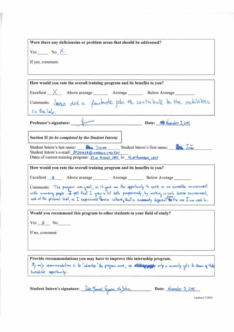

Related Documents