Progress In Electromagnetics Research C, Vol. 25, 179–191, 2012 NEW U-SHAPED DGS BANDSTOP FILTERS J.-K. Xiao 1, 2, * and Y.-F. Zhu 3 1 School of Electronical & Mechanical Engineering, Xidian University, Xi’an 710071, China 2 State Key Laboratory of Millimeter Waves, Nanjing 210096, China 3 School of Computer and Information, Hohai University, Changzhou 213022, China Abstract—In this paper, new microstrip bandstop filters with single band, dual-band and tri-band by using U-shaped defected ground structures are presented without the assistance of coupled lines or certain resonators, and the application of DGS is developed. The proposed bandstop filters have good performances of low loss, multi- band operation, transmission zeros which improve the filter frequency selectivity, and miniaturization because of the cascade of DGS and minimum defected patterns which reduce the circuit size. The new designs are demonstrated by measurement. 1. INTRODUCTION In recent years, there is growing interest in defected ground structures (DGS), and many microwave circuits, such as filter [1,2], power divider and power amplifier, etc., have been implemented by using DGS. Similar to the PBG (photonic bandgap) or EBG (electromagnetic bandgap) structure, defected ground structure is formed by etching a defected pattern on the metallic ground plane, which enhances the effective capacitance and inductance of microstrip line, and as a result, DGS has slow-wave characteristics and restrains the spurious responses by rejecting harmonic in microwave circuits, so the performances of filters or other microwave components are effectively improved. DGS exhibits the properties of rejecting electromagnetic waves in certain Received 18 September 2011, Accepted 14 November 2011, Scheduled 22 November 2011 * Corresponding author: Jian-Kang Xiao ([email protected]).

NEW U-SHAPED DGS BANDSTOP FILTERS J.-K. Xiao and Y. … · * Corresponding author: Jian-Kang Xiao ([email protected]). 180 Xiao and Zhu frequencies and directions, and the most interesting
Jan 28, 2019
Welcome message from author
This document is posted to help you gain knowledge. Please leave a comment to let me know what you think about it! Share it to your friends and learn new things together.
Transcript

Progress In Electromagnetics Research C, Vol. 25, 179–191, 2012
NEW U-SHAPED DGS BANDSTOP FILTERS
J.-K. Xiao1, 2, * and Y.-F. Zhu3
1School of Electronical & Mechanical Engineering, Xidian University,Xi’an 710071, China2State Key Laboratory of Millimeter Waves, Nanjing 210096, China3School of Computer and Information, Hohai University, Changzhou213022, China
Abstract—In this paper, new microstrip bandstop filters with singleband, dual-band and tri-band by using U-shaped defected groundstructures are presented without the assistance of coupled lines orcertain resonators, and the application of DGS is developed. Theproposed bandstop filters have good performances of low loss, multi-band operation, transmission zeros which improve the filter frequencyselectivity, and miniaturization because of the cascade of DGS andminimum defected patterns which reduce the circuit size. The newdesigns are demonstrated by measurement.
1. INTRODUCTION
In recent years, there is growing interest in defected ground structures(DGS), and many microwave circuits, such as filter [1, 2], power dividerand power amplifier, etc., have been implemented by using DGS.Similar to the PBG (photonic bandgap) or EBG (electromagneticbandgap) structure, defected ground structure is formed by etchinga defected pattern on the metallic ground plane, which enhances theeffective capacitance and inductance of microstrip line, and as a result,DGS has slow-wave characteristics and restrains the spurious responsesby rejecting harmonic in microwave circuits, so the performances offilters or other microwave components are effectively improved. DGSexhibits the properties of rejecting electromagnetic waves in certain
Received 18 September 2011, Accepted 14 November 2011, Scheduled 22 November 2011* Corresponding author: Jian-Kang Xiao ([email protected]).

180 Xiao and Zhu
frequencies and directions, and the most interesting applications forthese structures are the filtering of frequency bands or the suppressionof undesired spurious passbands and harmonics in microwave ormillimeter wave circuits.
Currently, the most applied DGSs are all kinds of dumbbelland spiral-shaped ones, however, these structures hardly satisfy therequirement of narrow band. [2] reports the dual-mode DGS resonatorand filter, [3] designs a dual-mode bandpass filter which assisted by U-shaped DGS to obtain a improved stopband performance and smallersize, and [4] designed dual-band bandstop filter with the assistance ofDGS and stepped impedance resonator. The most reported workson DGS filters are the implementation of low pass filters [5–9] byusing new DGS unit [7–9] or periodical DGS [10], and the reports onDGS bandstop filters especially the DGS assisted dual-band bandstopfilters are very limited. We have also noticed that most of the DGSassisted microwave filters including lowpass, bandpass and bandstopfilters consist of certain resonators or lines, and the DGS only plays arole of improving filter performances. The dual and tri-band bandstopfilters only using DGS patterns have not been reported.
RF bandstop filters are highly desired for their effectivesuppression of spurious signals. With the rapid development of modernwireless communication, bandstop filters with more operation bandsare attractive due to their ability to treat the unwanted signals ofRF circuits by using one single filter, which decrease the circuitsize and cost. Dual-band bandstop filters can filtrate the unwanteddouble-sideband spectrum of high power amplifiers and mixers. Inthis article, new technique of developing U-shaped DGS assisted dualand tri-band bandstop filters are presented without the assistance ofresonators or coupled lines, and the U-shaped DGS shows a betterstopband performance compared with conventional dumbbell ones.The ground plane of a standard 50-ohm microstrip line (ML) anda stepped-impedance microstrip line are perturbed by cascaded U-shaped DGSs to generate multi-band that is beneficial to narrow bandperformance and mutual coupling of this new DGS which createsmultiple-resonance characteristics in the frequency response. The newbandstop filters have more operation bands compared with relativereported works [4, 11, 12], and have advantages of novel structures,miniature size for the DGS cascade and reduced defection cells, andgood performances of transmission zeros and low loss. The designs areverified by experiment.

Progress In Electromagnetics Research C, Vol. 25, 2012 181
2. BANDSTOP FILTERS WITH SINGLE ANDDUAL-BAND
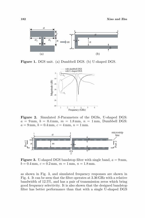
Currently, DGS plays important roles in RF circuits design.Conventional dumbbell-shaped DGS can be equivalent by a parallelLC circuit [13]. Inductance L denotes the operation of rectangularlattice in the defected unit, and capacitance C denotes the operationof slit between two rectangular lattices. L increases with the area ofrectangular lattice increasing, while C decreases with the width of slitincreasing. U-shaped DGS can be seen as a transformation of theconventional dumbbell DGS, as shown in Fig. 1, and the calculatedperformance variation of dumbbell DGS transform to the U-shapedDGS is shown in Table 1, which shows the center frequency and 3 dBbandwidth decrease with parameter a1 increasing. When a1 = a2, it isa dumbbell DGS, and when a1 increased to a certain value as a2 = 0,it is a U-shaped DGS. Simulated S parameters of the dumbbell-shapedDGS and U-shaped DGS are plotted in Fig. 2, and it can be seen thatU-shaped DGS has more obvious and narrow stopband performance,and a single DGS can’t create transmission zero. The equivalent circuitof U-shaped DGS can be expressed as a parallel LC circuit because ithas similar frequency characteristics to that of the dumbbell DGS. Theabove calculations are got by using microstrip material with relativedielectric constant of 10.2 and thickness of 1.27 mm. Q values andfrequency responses versus different parameters for the U-shaped DGSare analyzed in literature [14].
We know that U-shaped DGS has better stopband performancethan the traditional dumbbell DGS from the above analysis. Here, asingle band bandstop filter using double U-shaped DGSs is designed,
Table 1. Performance variation of dumbbell DGS transform to theU-shaped DGS. a = 6mm, b = 0.4mm, c = 1mm, n = 2mm.
a1 (mm) Center frequency f0 (GHz) 3 dB bandwidth (GHz)2.8 6.15 2.53.2 6.07 2.373.6 5.91 2.214.0 5.5 1.864.4 5.3 1.714.8 5.05 1.565.2 4.72 1.395.6 4.5 1.27
182 Xiao and Zhu
b
c
a
na2 a1
a
nm
b
b
(a) (b)
Figure 1. DGS unit. (a) Dumbbell DGS. (b) U-shaped DGS.
1 2 3 4 5 6-60
-50
-40
-30
-20
-10
0S
21
S11
Mag
nitu
de (
dB)
Frequency (GHz)
with dumbbell DGS with U-shaped DGS
Figure 2. Simulated S-Parameters of the DGSs, U-shaped DGS:a = 9mm, b = 0.4mm, m = 1.8mm, n = 1 mm, Dumbbell DGS:a = 9 mm, b = 0.4mm, c = 4 mm, n = 1 mm.
a
mn
b
b
b
c
microstrip line
Po
rt
1
Port
2
Figure 3. U-shaped DGS bandstop filter with single band, a = 9mm,b = 0.4mm, c = 0.2mm, m = 1mm, n = 1.8mm.
as shown in Fig. 3, and simulated frequency responses are shown inFig. 4. It can be seen that the filter operates at 3.36GHz with a relativebandwidth of 12.5%, and has a pair of transmission zeros which bringgood frequency selectivity. It is also shown that the designed bandstopfilter has better performance than that with a single U-shaped DGS

Progress In Electromagnetics Research C, Vol. 25, 2012 183
1 2 3 4 5 6-60
-50
-40
-30
-20
-10
0
S11
S 21
Mag
nit
ud
e (d
B)
Frequency(GHz)
Figure 4. Simulated frequency responses of the single band U-shapedDGS bandstop filter.
(a) (b)
Figure 5. Photograph of the fabricated hardware. (a) Top view.(b) Bottom view.
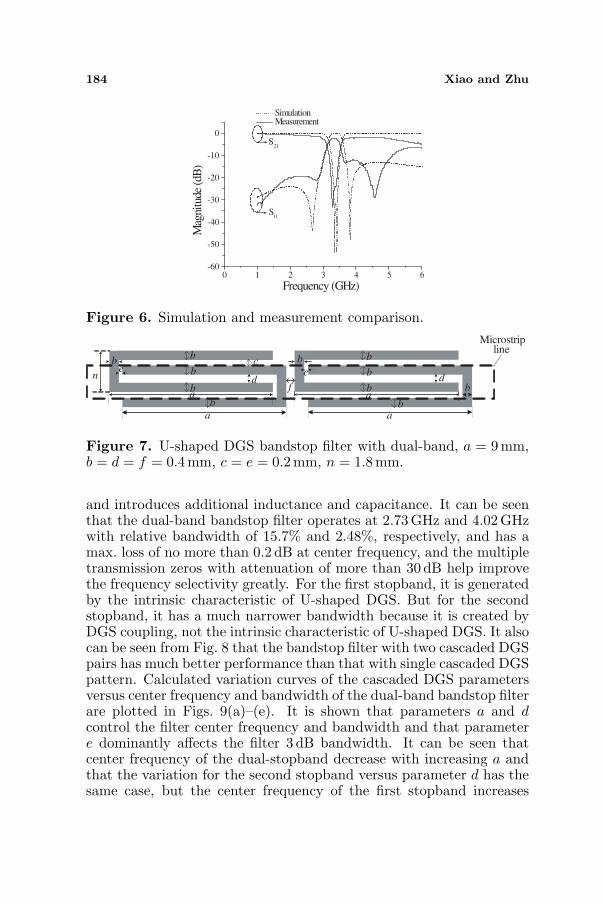
as shown in Fig. 2, and a much wider bandwidth of stopband andsmaller circuit size (circuit size reduction of about 34.5%) than theresults shown in [14]. All of the filters in this paper are designed onceramic substrate with relative dielectric constant of 10.2 and thicknessof 1.27 mm. Input port and output port are microstrip lines withcharacteristic impedance of 50Ω. In order to verify the design, thebandstop filter with double U-shaped DGS is fabricated and tested,and photograph of the hardware is shown in Fig. 5, and the measuredresults are shown in Fig. 6. The measurements which are got by AgilentE5071C vector network analyzer are in agreement with the simulation.
A dual-band bandstop filter is presented, as shown in Fig. 7,and the simulated frequency responses are shown in Fig. 8. Here,four U-shaped DGSs with identical dimensions are used to form twocascaded pairs to create dual-resonance characteristics in the frequencyresponse. We know that the U-shaped DGSs including the uniformperiodical ones only generate a single stopband in a certain frequencyband, such as 1–5GHz, and the 2nd and 3rd stopbands appear inthe frequency band which is more than 5GHz, but the cascaded U-shaped DGSs can generate more stopbands in a certain band of 1–5GHz because the action of DGS coupling and, simultaneously, thecascaded U-shaped DGS increases the electric length of microstrip line
184 Xiao and Zhu
0 1 2 3 4 5 6-60
-50
-40
-30
-20
-10
0S
21
S11
Mag
nitu
de (
dB)
Frequency (GHz)
Simulation Measurement
Figure 6. Simulation and measurement comparison.
a
a a
b
b
b
b
b
b
b
b
bd
be e
fn
b
a
Microstrip line
c
d
Figure 7. U-shaped DGS bandstop filter with dual-band, a = 9mm,b = d = f = 0.4mm, c = e = 0.2mm, n = 1.8mm.
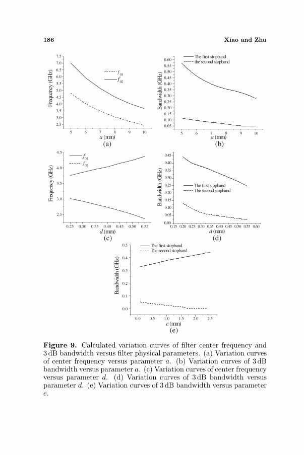
and introduces additional inductance and capacitance. It can be seenthat the dual-band bandstop filter operates at 2.73GHz and 4.02 GHzwith relative bandwidth of 15.7% and 2.48%, respectively, and has amax. loss of no more than 0.2 dB at center frequency, and the multipletransmission zeros with attenuation of more than 30 dB help improvethe frequency selectivity greatly. For the first stopband, it is generatedby the intrinsic characteristic of U-shaped DGS. But for the secondstopband, it has a much narrower bandwidth because it is created byDGS coupling, not the intrinsic characteristic of U-shaped DGS. It alsocan be seen from Fig. 8 that the bandstop filter with two cascaded DGSpairs has much better performance than that with single cascaded DGSpattern. Calculated variation curves of the cascaded DGS parametersversus center frequency and bandwidth of the dual-band bandstop filterare plotted in Figs. 9(a)–(e). It is shown that parameters a and dcontrol the filter center frequency and bandwidth and that parametere dominantly affects the filter 3 dB bandwidth. It can be seen thatcenter frequency of the dual-stopband decrease with increasing a andthat the variation for the second stopband versus parameter d has thesame case, but the center frequency of the first stopband increases

Progress In Electromagnetics Research C, Vol. 25, 2012 185
1 2 3 4 5
-80
-60
-40
-20
0
with single cascaded structure
1 2 3 4 5 6
-70
-60
-50
-40
-30
-20
-10
0
Mag
nitu
de (
dB)
Frequency (GHz)
S11
S21
Mag
nitu
de (
dB)
Frequency (GHz)
Figure 8. Simulated frequency responses of the dual-band DGSbandstop filter.
with parameter d increasing. Where, f0i is the i-th center frequencyof the dual-stopband, i = 1, 2. The figures also show that the 3-dBbandwidth of the dual-stopband decreases with parameters a and dincreasing. However, the bandwidth of the first and second stopbandshave the opposite variation trends with increasing parameter e.
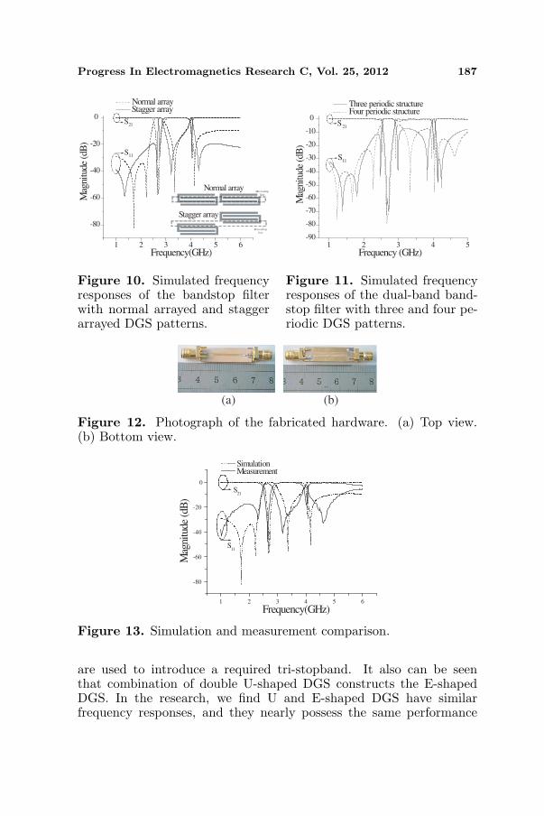
In order to analyze the proposed dual-band bandstop filter indetail, comparison of the bandstop filter with normal arrayed andstagger arrayed DGS patterns is given in Fig. 10, and comparison of thebandstop filter with different periodic structures is shown in Fig. 11. Itcan be seen that with stagger arrayed DGS patterns, bandwidth of thefirst stopband is decreased and controllable by the coupling betweenthe two DGS patterns. It can be seen from Fig. 11 that filter bandwidthhas no obvious changes with three and four periodic DGS patterns. Inthe research, we find that the bandwidth of the rejection band willbe extended by using 2 periodical cascaded patterns compared with asingle cascaded pattern. However, more periodic DGS patterns havenearly no effect on filter bandwidth but introduce more transmissionzeros, which increases the circuit size. Fig. 12 shows the photograph ofthe fabricated dual-band hardware, which has a circuit size reductionof about 93% compared with the reported dual-band bandstop filterin [15]. Fig. 13 shows the measured results, which are similar to thesimulation.
3. BANDSTOP FILTERS WITH TRI-BAND
In order to show the effectiveness of the U-shaped DGS in bandstopfilter design, tri-band bandstop filters are also designed, as shownin Fig. 14. Where, 50 Ω ML and stepped impedance ML are usedas comparison, and six U-shaped DGS cells with cascade coupling
186 Xiao and Zhu
5 6 7 8 9 10
2.5
3.0
3.5
4.0
4.5
5.0
5.5
6.0
6.5
7.0
7.5
Fre
quen
cy (
GH
z)
a (mm)
f01
f02
5 6 7 8 9 10
0.05
0.10
0.15
0.20
0.25
0.30
0.35
0.40
0.45
0.50
0.55
0.60
Ban
dwid
th (
GH
z)
a (mm)
The first stopband the second stopband
0.25 0.30 0.35 0.40 0.45 0.50 0.55
2.5
3.0
3.5
4.0
4.5
Fre
quen
cy (
GH
z)
d (mm)
f01
f02
0.15 0.20 0.25 0.30 0.35 0.40 0.45 0.50 0.55 0.600.00
0.05
0.10
0.15
0.20
0.25
0.30
0.35
0.40
0.45B
andw
idth
(G
Hz)
d (mm)
The first stopband The second stopband
0.0 0.5 1.0 1.5 2.0 2.5
0.0
0.1
0.2
0.3
0.4
0.5
Ban
dwid
th (
GH
z)
e (mm)
The first stopband The second stopband
(a) (b)
(c) (d)
(e)
Figure 9. Calculated variation curves of filter center frequency and3 dB bandwidth versus filter physical parameters. (a) Variation curvesof center frequency versus parameter a. (b) Variation curves of 3 dBbandwidth versus parameter a. (c) Variation curves of center frequencyversus parameter d. (d) Variation curves of 3 dB bandwidth versusparameter d. (e) Variation curves of 3 dB bandwidth versus parametere.
Progress In Electromagnetics Research C, Vol. 25, 2012 187
1 2 3 4 5 6
-80
-60
-40
-20
0
Microstrip
line
Microstrip
line
Stagger array
Normal array
S11
S21
Mag
nitu
de (
dB)
Frequency(GHz)
Normal array Stagger array
Figure 10. Simulated frequencyresponses of the bandstop filterwith normal arrayed and staggerarrayed DGS patterns.
1 2 3 4 5-90
-80
-70
-60
-50
-40
-30
-20
-10
0S
21
S11
Mag
nitu
de (
dB)
Frequency (GHz)
Three periodic structure Four periodic structure
Figure 11. Simulated frequencyresponses of the dual-band band-stop filter with three and four pe-riodic DGS patterns.
(a) (b)
Figure 12. Photograph of the fabricated hardware. (a) Top view.(b) Bottom view.
1 2 3 4 5 6
-80
-60
-40
-20
0
S11
S21
Mag
nitu
de (
dB)
Frequency(GHz)
Simulation Measurement
Figure 13. Simulation and measurement comparison.
are used to introduce a required tri-stopband. It also can be seenthat combination of double U-shaped DGS constructs the E-shapedDGS. In the research, we find U and E-shaped DGS have similarfrequency responses, and they nearly possess the same performance

188 Xiao and Zhu
a
cc
ed
d
d
d
bd
d
db
bbn m
a
c
d
e
d
d
d
d
b
c
a
bb
b
d
dmn
a
h
Microstrip line
Stepped impedance microstrip line
a
cc
e
d
d
dd
b
d
d
d
bbb
n m
a
c
d
e
d
d
d
d
b
c
a
b
b
b
d
d mn
a
hp
9.6mm
0.4mm0.4mm
9.6mm0.4
mm
1.2
mm
1.6
mm
Po
rt 1
Po
rt 2
(a)
(b)
(c)
Figure 14. U-shaped DGS bandstop filter with tri-band, a = 9 mm,b = 0.2mm, c = 0.3mm, d = 0.4mm, e = 0.5 mm, h = 0.6mm,m = 3.3mm, n = 1.8mm. (a) With 50-ohm standard microstrip line.(b) With stepped impedance microstrip line. (c) Stepped impedancemicrostrip line.
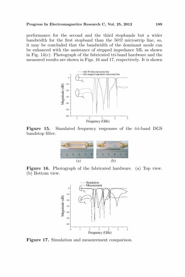
if have the same dimension. Simulated filter frequency responses areshown in Fig. 15, and it can be seen that with stepped impedancemicrostrip line, the tri-band bandstop filter centers at 2.56 GHz,3.42GHz and 4.08 GHz with relative bandwidth of 12.1%, 2.93% and2.45%, respectively, and also implements low loss and transmissionzeros, as the real line shows. It also can be seen that the bandstopfilter with stepped impedance microstrip line has nearly the same
Progress In Electromagnetics Research C, Vol. 25, 2012 189
performance for the second and the third stopbands but a widerbandwidth for the first stopband than the 50 Ω microstrip line, so,it may be concluded that the bandwidth of the dominant mode canbe enhanced with the assistance of stepped impedance ML as shownin Fig. 14(c). Photograph of the fabricated tri-band hardware and themeasured results are shown in Figs. 16 and 17, respectively. It is shown
1 2 3 4 5-60
-50
-40
-30
-20
-10
0
S11
S21
Mag
nitu
de (
dB)
Frequency (GHz)
with 50-ohm microstrip line with stepped impedance microstrip line
Figure 15. Simulated frequency responses of the tri-band DGSbandstop filter.
(a) (b)
Figure 16. Photograph of the fabricated hardware. (a) Top view.(b) Bottom view.
0 1 2 3 4 5 6
-60
-50
-40
-30
-20
-10
0
S11
S21
Mag
nitu
de (
dB)
Frequency (GHz)
Simulation Measurement
Figure 17. Simulation and measurement comparison.

190 Xiao and Zhu
that the measurement is similar to the simulation, which demonstratesthe correctness of our design. The measured discrepancies are due tothe precision of EM simulation and fabrication uncertainty.
4. CONCLUSION
New multiple-band microstrip bandstop filters with good performancesof low loss and transmission zeros by using cascaded U-shaped DGSare developed, and the cascading creates dual and tri-resonancecharacteristics in the frequency response. A tri-band bandstop filterwith standard 50 Ω microstrip line and stepped-impedance microstripline are compared, which shows that the latter introduces a widerbandwidth for the first stopband. Compared with the other DGSassisted microwave filters including lowpass, bandpass and bandstopfilters which consist of certain resonators or lines, our new designdevelops the DGS cascade structures without the assistance ofresonators or lines to realize multi-stopband, which not only introducesthe desired stopbands, but also implements miniaturization. The newdesigns are fabricated and measured, and the experiment demonstratesthe design.
ACKNOWLEDGMENT
This work was supported in part by Research Fund of China StateKey Laboratory of Millimeter Waves (K201107). The authors sincerelythank the anonymous reviewers for their valuable suggestions.
REFERENCES
1. Wu, G.-L., W. Mu, X.-W. Dai, and Y.-C. Jiao, “Design of noveldual-band bandpass filter with microstrip meander-loop resonatorand CSRR DGS,” Progress In Electromagnetics Research, Vol. 78,17–24, 2008.
2. Wang, L. and B.-R. Guan, “Compact dual-mode DGS resonatorsand filters,” Progress In Electromagnetics Research Letters,Vol. 25, 47–55, 2011.
3. Chotjit, S., S. Chaimool, and P. Akkaraeakthalin,“ A miniaturizeddual-mode bandpass filter using triangular loop resonator withwide stopband by U-Shaped defected ground structure (DGS),”Asia-Pacific Microwave Conference (APMC), 1–4, 2007.
4. Che, W. Q., W. J. Feng, and K. Deng, “Microstrip dual-band bandstop filter of defected ground structure and stepped

Progress In Electromagnetics Research C, Vol. 25, 2012 191
impedance resonators,” International Journal of Electronics,Vol. 97, No. 11, 1351–1359, 2010.
5. Chen, J., Z.-B. Weng, Y.-C. Jiao, and F.-S. Zhang, “Lowpass filterdesign of hilbert curve ring defected ground structure,” ProgressIn Electromagnetics Research, Vol. 70, 269–280, 2007.
6. Chen, X.-Q., R. Li, S.-J. Shi, et al., “A novel low pass filterusing elliptic shape defected ground sstructure,” Progress InElectromagnetics Research B, Vol. 9, 117–126, 2008.
7. Verma, A. K. and A. Kumar, “Design of low-pass filters usingsome defected ground structures,” AEU-International Journal ofElectronics and Communications, Vol. 65, No. 10, 864–872, 2011.
8. Al Sharkawy, M. H., D. Abd El Aziz, and E. Galal, “Aminiaturized lowpass/bandpass filter using double arrow headdefected ground structure with centered etched ellipse,” ProgressIn Electromagnetics Research Letters, Vol. 24, 99–107, 2011.
9. Mohra, A. S., “Microstrip low pass filter with wideband rejectionusing opened circuit stubs and Z-slots defected ground structures,”Microwave and Optical Technology Letters, Vol. 53, No. 4, 811–815, 2011.
10. Xiao, J.-K., Y.-F. Zhu, and S. F. Jeffrey “DGS lowpass filtersextend wide stopbands,” Microwaves & RF, Vol. 50, No. 3, 66–76, 2011.
11. Rehman, S. U., A. F. Sheta, and M. Alkanhal, “Compact band-stop filter using defected ground structure (DGS),” Saudi Inter-national Electronics, Communications and Photonics Conference,SIECPC, 2011.
12. Yang, M. H., J. Xu, Y. L. Dong, et al., “A novel open-loopDGS for compact bandstop filter with improved Q factor,” The8th International Symposium on Antennas, Propagation and EMTheory Proceedings, 649–652, 2008.
13. Park, J. I., C. S. Kim, J. S. Park, et al., “Modeling of photonicbandgap and its application for the low-pass filter design,” Asia-Pacific Microwave Conference Proceedings, 331–334, 1999.
14. Woo, D.-J., T.-K. Lee, J.-W. Lee, et al., “Novel U-Slot and V-SlotDGSs for bandstop filter with improved Q factor,” IEEE Trans.on Microwave Theory and Techniques, Vol. 54, No. 6, 2840–2847,2006.
15. Chin, K.-S., J.-H. Yeh, and S.-H. Chao, “Compact dual-band bandstop filters using stepped-impedance resonators,” IEEEMicrowave and Wireless Components Letters, Vol. 17, No. 12, 849–851, 2007.
Related Documents


![[B3] XIAO Guangrui_TF 2012 Xiao Sichuan Roads Development Projects](https://static.cupdf.com/doc/110x72/577ce47b1a28abf1038e7451/b3-xiao-guangruitf-2012-xiao-sichuan-roads-development-projects.jpg)


