Álvaro Cunha & Elsa Caetano Álvaro Cunha & Elsa Caetano New trends in dynamic bridge testing New trends in dynamic bridge testing The perspective of FEUP The perspective of FEUP

Welcome message from author
This document is posted to help you gain knowledge. Please leave a comment to let me know what you think about it! Share it to your friends and learn new things together.
Transcript

Álvaro Cunha & Elsa CaetanoÁlvaro Cunha & Elsa Caetano
New trends in dynamic bridge testing New trends in dynamic bridge testing The perspective of FEUPThe perspective of FEUP

SUMMARY
• Modal identification• Finite element correlation and updating• Vibration based damage detection• Pedestrian induced vibrations• Traffic induced vibrations• Cable vibrations• Structural monitoring• Control of vibrations

MODAL IDENTIFICATION
Vasco da Gama Bridge

AMBIENT VIBRATION TEST
z
x y
1J
1M2M
2J
3M
3J
5M
5J4M
4J6J
6M7M
7J8J
8M9J
9M10J
10M11J
11M12,13,14M27M
27J12,13,14J
15J
15M16J
16M17J
17M18J
18M19J
19M28J
28M29J
29M
20J
20M
21J
21M22J
22M23J
23M
24J
24M
25J
25M
26M
26J
P1P2
P3PN
PS
P4
P5P6
(North)LISBOA
SETÚBAL(South)
Figure 1: Schematic representation of Vasco da Gama cable-stayed bridge andindication of the measurement sections used in the dynamic tests
6 triaxial accelerographsPrecision: <1g/216=0,015mgSampling frequency: 50 HzFrequency resolution: <0,01Hz
Vasco da Gama Bridge

1st vertical bending mode
2nd vertical bending mode
Free vibration test
Stochastic identification
f=0.338 Hz40,016,0 −=ξ
Free vibration test
Stochastic identification
f=0.339 Hz41,0=ξ
f=0.456 Hz27,019,0 −=ξ
32,0=ξf=0.457 Hz
MODAL IDENTIFICATION

1st torsion mode
2nd torsion mode
Free vibration test
f=0.467 Hz36,014,0 −=ξ
Stochastic identification
f=0.469 Hz34,0=ξ
Free vibration test
f=0.591 Hz39,030,0 −=ξ
Stochastic identification
f=0.622 Hz
MODAL IDENTIFICATION

FREE VIBRATION TEST• Identification of modal
damping factors
(b)
p
1.00E-04
1.00E-03
1.00E-02
1.00E-01
1.00E+00
0 0.1 0.2 0.3 0.4 0.5 0.6 0.7 0.8 0.9 1
Am
plitu
de F
FT (m
g)
GSR-204/206
00.20.40.60.8
11.21.41.61.8
2
100 200 300 400 500 600 700
Envolvente
C urva ajustada 200-500s
ξ=0.24%
-10.00-8.00-6.00-4.00-2.000.002.004.006.008.00
10.00
100 150 200 250 300 350
GSR-200
1/3 span North, half-sum vertical component

MODAL IDENTIFICATION
Trends for development
• Instrumentation- Wireless solution (time synchronization by GPS)- Conventional cables solution allowing in-situ modal identification
- Innovative data acquisition with local digitizationand signal conditioning, single cable transmissionand remote control from the lab (GSM or Internet)
• Output-only modal identification software- Allowing objective and automatic identification

The old Hintze Ribeiro Bridge
7 spans, 6 masonry piers
Steel truss deck
Wood piles
Construction: 1885 (116 y.o.)
FINITE ELEMENT CORRELATION

COLAPSE OF HINTZE RIBEIRO BRIDGE
March 2001

THE NEW HINTZE RIBEIRO BRIDGE
April 2002

AMBIENT VIBRATION TEST
Longitudinalbeam
• Definition of 2 reference stations (6 and 9)• Measurement at supports, midspan, 1/4th span, top and base
of piers
• Measurements along one of the steel I-girders
• 4 seismographs, 18-bit A/Dconverter• 1 laptop

AMBIENT VIBRATION TEST
Vertical Direction
4.028
1.465
1.7821.953 2.197
2.539
2.710
2.905
3.5403.809
1.00E-05
1.00E-04
1.00E-03
1.00E-02
1.00E-01
1.00E+00
0 1 2 3 4 5
Frequency (Hz)
Am
plitu
de P
SD
N
Average normalized power spectra

FINITE ELEMENT CORRELATION
-2
-1.5
-1
-0.5
0
0.5
1
1.5
2
0 50 100 150 200 250 300
Experimental, Freq.=1.451HzNumerical, Freq.= 1.608Hz
Identified vs calculated modes: vertical component
-2
-1.5
-1
-0.5
0
0.5
1
1.5
0 50 100 150 200 250 300
Experimental, Freq.=1.786HzNumerical, Freq.= 1.896Hz

FINITE ELEMENT CORRELATION
-1
-0.5
0
0.5
1
1.5
2
0 50 100 150 200 250 300
Experimental, Freq.=1.144Hz
Numerical, Freq.= =0.715Hz
Identified vs calculated modes: lateral component
-2.5
-2
-1.5
-1
-0.5
0
0.5
1
1.5
2
0 50 100 150 200 250 300
Experimental, Freq.=1.641HzNumerical, Freq.= =.892Hz

FINITE ELEMENT CORRELATION
Calculated frequency (Hz)
Identified frequency (Hz)
Type of mode (*)
1.608 1.465 1st vertical 1.896 1.782 2nd vertical 2.291 2.710 3rd vertical 2.291 2.890 4th vertical 3.458 3.54 5th vertical
Calculated
frequency (Hz) Identified
frequency (Hz) Type of mode (*)
0.715 1.147 1st lateral 0.892 1.636 2nd lateral 1.180 2.881 3rd lateral
Identified vs calculated natural frequencies

Z=120.50
Z=1119.00
Z=126.65
Z=124.50Z=124.50
Z=119.00
7.50 10.00
5.00
10.0061.00
3.0010.00
0.40
28.00
Z=124.50-126.651% 1%
3.800.403.000.40
1.00
0.15
FINITE ELEMENT UPDATING
L1=30m; L2=28m
T0=750kN x 4
Stress-ribbon footbridge

EXPERIMENTAL ASSESSMENT
0.00001
0.0001
0.001
0.01
0.1
0 5 10 15
Frequência (Hz)
PSD
méd
io (m
/s2)
Ref. 1Ref. 2
1 2 3 4 5 6 7 8 Ref 1 Ref 2
9
10 11
12 13 14 15 16 17 18 19 20
Moving measurement points
Reference points
AMBIENT VIBRATION TEST

Discretization of the deck in beam finite elements with the geometry corresponding to the design configuration
NUMERICAL MODELLING
Discretization of the deck in beam finite elements with the geometry corresponding to the measured configuration
Model 1
Model 2
-0.500
0.000
0.500
1.000
1.500
2.000
2.500
0 10 20 30 40 50 60
Comprimento (m)
Altu
ra (m
)
Medido
Projecto
Calculado/projecto
Calculado/corrigido

NUMERICAL MODELLING
Discretization of the deck in truss finite elements, with progressive loading and activation of beam elements connecting the nodes of the truss elements
Consideration of partial rotations between beam elements to simulate the lack of sealing of the joints.Reduction of the area and inertia of the beam elements to simulate the effects of cracking and lack of adherence between precast and in situ concrete
Discretization of the deck in truss finite elements with the cables’ axial stiffness (neglecting bending stiffness), adjusting the initial cables tension so as to obtain the measured longitudinal profile after progressive application of the loads
Final model
Model 4
Model 3

Modo nº Freq. medida (Hz) Modelo 1 Freq. (Hz)
Modelo 2 Freq. (Hz)
Modelo 3 Freq. (Hz)
Modelo 4 Freq. (Hz)
Modelo final Freq. (Hz)
1 1.116 0.849 0.794 0.724 1.096 .980 2 2.027 2.448 2.654 0.937 2.442 2.033 3 2.115 1.902 1.822 1.446 3.813 2.250 4 2.483 2.096 2.002 1.547 3.895 2.550 5 - 2.217 7.496 3.651 6 3.815 3.415 3.401 3.376 7.569 4.115 7 4.387 3.782 3.630 3.034 12.4 4.676
FINITE ELEMENT UPDATINGFinal model
Discretization of the deck in truss finite elements, with progressive loading and activation of beam elements. Consideration of partial rotations between beam elements to simulate the lack of sealing of the joints. Reduction of the area and inertia of the beam elements to simulate the effects of cracking and lack of adherence between precast and in situ concrete.

Identified vs calculated mode shapes
-3
-2
-1
0
1
2
0 10 20 30 40 50 60
Freq.=1.116HzNumerical
-3-2-10123
0 10 20 30 40 50 60
Freq.=2.027HzNumerical
-3-2-10123
0 10 20 30 40 50 60
Freq.=2.115HzNumerical
-3
-2
-1
0
1
2
0 10 20 30 40 50 60
Freq.=2.483HzNumerical
-3-2-1012
0 10 20 30 40 50 60
Freq.=3.651Hz
-3-2-10123
0 10 20 30 40 50 60
Freq.=3.815HzNumerical
-3
-2
-1
0
1
2
0 10 20 30 40 50 60
Freq.=4.387HzNumerical
-4
-2
0
2
4
0 10 20 30 40 50 60
Freq.=5.829Hz
Numerical
FINITE ELEMENT UPDATING

FINITE ELEMENT UPDATINGVIBRATION BASED DAMAGE DETECTION
Trends for development• Application of automatic procedures for finite
element updating and damage detection• Development of laboratory tests on beams• Introduction of realistic damage scenarios in an
existing bridge

PEDESTRIAN INDUCED VIBRATIONS
Stainless steel footbridge
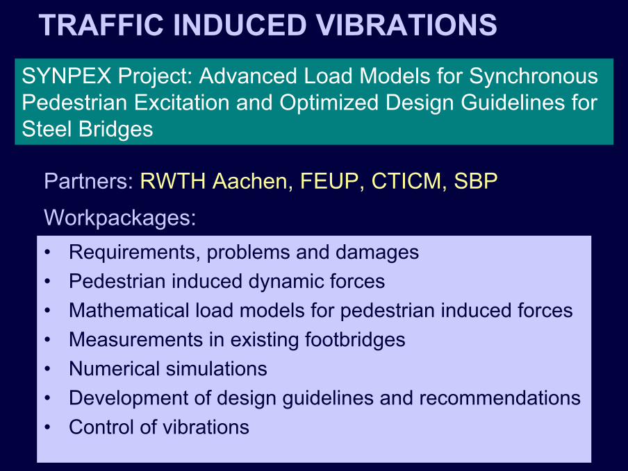
TRAFFIC INDUCED VIBRATIONSSYNPEX Project: Advanced Load Models for Synchronous Pedestrian Excitation and Optimized Design Guidelines for Steel Bridges
• Requirements, problems and damages• Pedestrian induced dynamic forces• Mathematical load models for pedestrian induced forces• Measurements in existing footbridges• Numerical simulations• Development of design guidelines and recommendations• Control of vibrations
Workpackages:Partners: RWTH Aachen, FEUP, CTICM, SBP

TRAFFIC INDUCED VIBRATIONS
Trends for development
• Measurement of pedestrian forces• Methods for numerical prediction of maximum levels
of vibration• Design and simulation of control of vibration devices

ROADWAY BRIDGESEXPERIMENTAL ASSESSMENT
Strain gages Load cells Tests

ROADWAY BRIDGES
-0.50
-0.25
0.00
0.25
0.50
0.75
1.00
1.25
5.00 6.00 7.00 8.00 9.00 10.00 11.00 12.00 13.00 14.00 15.00 16.00 17.00
t (s)
εdyn
(t)
/ εst
a
ExperimentalNumerical
DAFexp =1.188DAFnum =1.140
NUMERICAL MODELLING AND VALIDATION
Static and dynamic tests
G 2 G 1
1M 1 , I
3 .6 5 2 .2 0
T ra ile r
T ra c to r
, IM 2 2
2z θ 2 1z
z
M
s 2 j
t 2 j
k s 2 jc
t 2 jk t 2 jc
t 1 j
zr 1 jk
z t 2 j
zr 2 jk
M
s 1 j
t 1 j
k s 1 jc
t 1 jk t1 jc
r 1 jQr 2 jQ
1 .3 5 0 .9 0

RAILWAY BRIDGES
Trends for development
• Structural integrity assessment of old metalic railway bridges (fatigue assessment)
• High speed railway traffic- Dynamic effects in bridges- Vibrations in soils

CABLE VIBRATIONSSTRUCTURAL MONITORING
Cable vibrations at GUADIANA BRIDGE
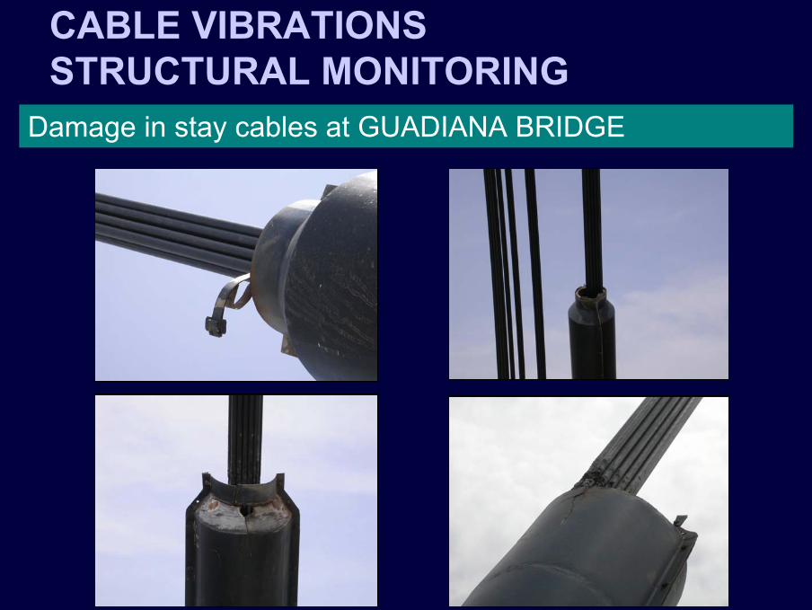
CABLE VIBRATIONSSTRUCTURAL MONITORING
Damage in stay cables at GUADIANA BRIDGE

• Numerical modelling of the dynamic behaviour of a cable-stayed bridge
• Development of a multi-sensorial distributed instrumentation system
• Experimental characterization of the dynamic behaviour of the bridge
• Test and development of force sensors• Development of video camera for vibration measurements• Development of monitoring software• Laboratory tests of physical models of stay cables• Study of passive and semi-active control solutions
Workpackages:
CABLE VIBRATIONSSTRUCTURAL MONITORING
Cable vibrations in cable-stayed bridgesFCT Project

STRUCTURAL MONITORING
Trends for development
• Robust commercial solution• Innovative solution:
- multi-sensorial distributed instrumentation system- data acquisition with local digitizationand signal conditioning
- single cable transmission- remote control from the lab (GSM or Internet)

CONTROL OF VIBRATIONS
Trends for development
• Control of vibrations in footbridges• Control of vibrations in stay cables• Design and simulation of:
- passive- active- semi-active
solutions

CONCLUSION
MAIN TOPICS FOR JOINT RESEARCH
• Structural Monitoring and Damage Detection in Bridges
• Analysis and Control of Traffic Induced Vibrations in Bridges
Related Documents