New Techniques in Radiation therapy Moderator: Dr S C Sharma Department of Radiotherapy PGIMER Chandigarh

New Techniques in Radiation Therapy
Nov 13, 2014
Welcome message from author
This document is posted to help you gain knowledge. Please leave a comment to let me know what you think about it! Share it to your friends and learn new things together.
Transcript

New Techniques in Radiation therapy
Moderator:Dr S C SharmaDepartment of RadiotherapyPGIMERChandigarh

Trends
1990 1995 2000 20050
500
1000
1500
2000
2500Number of Publications in Google Scholar
3 DCRT IMRT IGRT
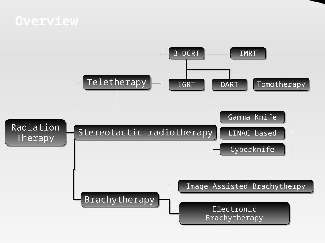
Overview
3 DCRT
Radiation Therapy
Teletherapy
Brachytherapy
IMRT
IGRT DART
Electronic Brachytherapy
Tomotherapy
Image Assisted Brachytherpy
Stereotactic radiotherapyGamma Knife
LINAC based
Cyberknife

Solutions ?
Develop technologies to circumvent limitationsUse alternative radiation modalities
Electrons
Protons
Neutrons
π- Mesons
Heavy Charged Nuclei
Antiprotons

Development Timeline
1990
1960 Proimos develops gravity oriented
blocking and conformal field shaping
1980 Brahame conceptualized inverse planning
& gives prototype algorithm for (1982-88)1st inverse planning algorithm developed by Webb (1989)
1970Tracking Cobalt unit invented
at Royal Free Hospital
1950
Takahashi discusses conformal RT1st MLCs invented (1959)
Boyer and Webb develop principle of static IMRT (1991)
Carol demonstrates NOMOS MiMIC (1992)Tomotherapy developed in Wisconsin (1993)
Stein develops optimal dMLC equations (1994)First discussion of Robotic
IMRT (1999)
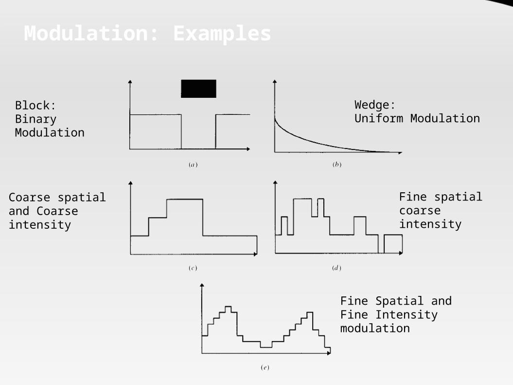
Modulation: Examples
Block: Binary Modulation
Wedge:Uniform Modulation
Coarse spatial and Coarse intensity
Fine spatial coarse intensity
Fine Spatial and Fine Intensity modulation
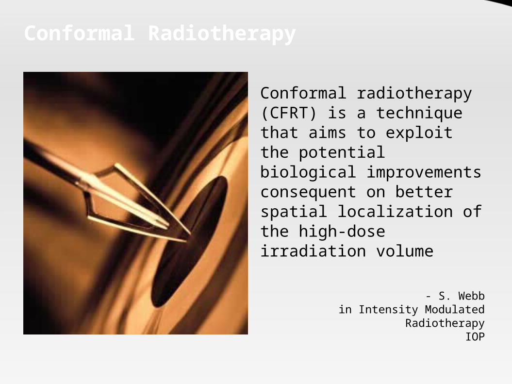
Conformal Radiotherapy
Conformal radiotherapy (CFRT) is a technique that aims to exploit the potential biological improvements consequent on better spatial localization of the high-dose irradiation volume
- S. Webbin Intensity Modulated Radiotherapy
IOP

Problems in conformation
Nature of the photon beam is the biggest impediment
Has an entrance dose.
Has an exit dose. Follows the inverse
square law.

Types of CFRT
Two broad subtypes : Techniques aiming to
employ geometric fieldshaping alone
Techniques to modulate the intensity of fluence across the geometrically-shaped field (IMRT)

Modulation : Intensity or Fluence ?
Intensity Modulation is a misnomer – The actual term is Fluence
Fluence referes to the number of “particles” incident on an unit area (m-2)

How to modulate intensity
Cast metal compensator Jaw defined static fields Multiple-static MLC-shaped fields Dynamic MLC techniques (DMLC)
including modulated arc therapy (IMAT) Binary MLCs - NOMOS MIMiC and in
tomotherapy Robot delivered IMRT Scanning attenuating bar Swept pencils of radiation (Race Track
Microtron - Scanditronix)

Comparision
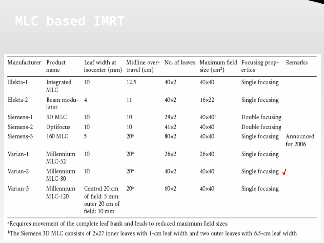
MLC based IMRT
√
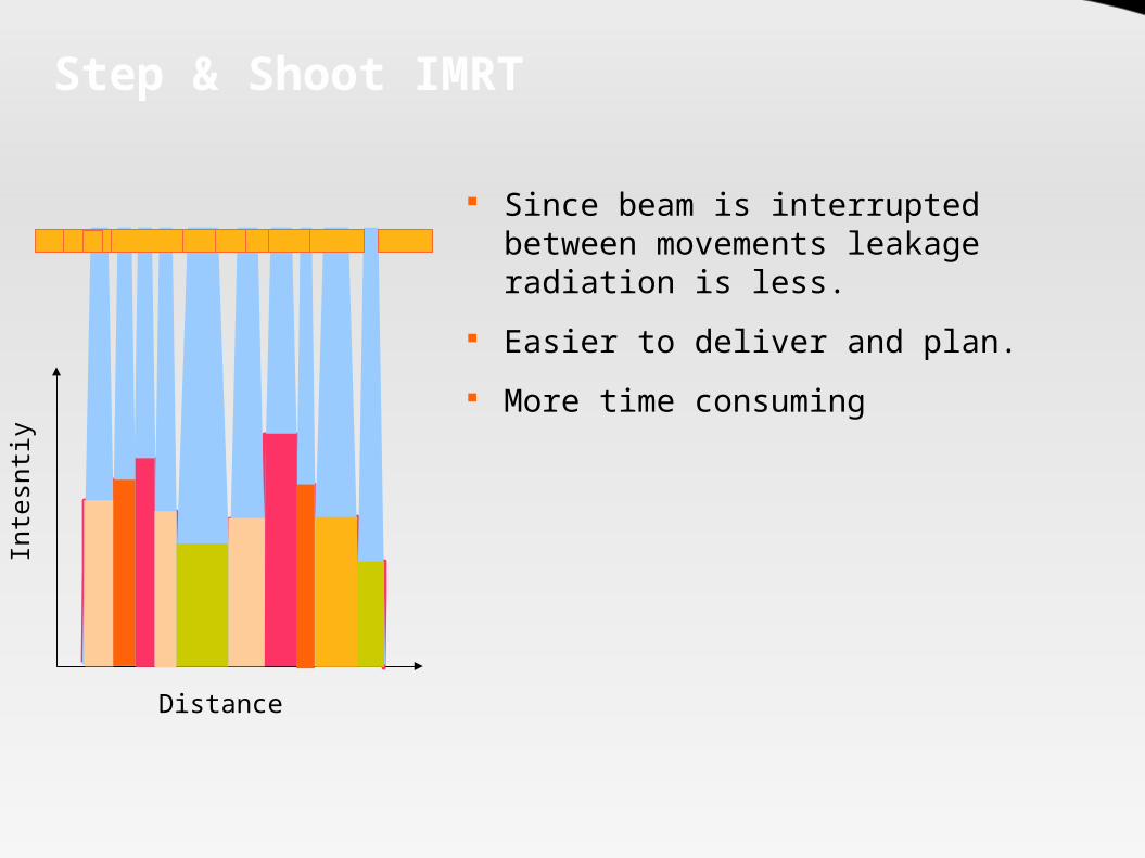
Step & Shoot IMRTIn
tesn
tiy
Distance
Since beam is interrupted between movements leakage radiation is less.
Easier to deliver and plan. More time consuming

Dynamic IMRT
Faster than Static IMRT Smooth intensity modulation
acheived Beam remains on throughout –
leakage radiation increased More susceptible to tumor
motion related errors. Additional QA required for MLC
motion accuracy.
Inte
sntiy
Distance

Caveats: Conformal Therapy
Significantly increased expenditure: Machine with treatment capability Imaging equipment: Planning and Verification Software and Computer hardware
Extensive physics manpower and time required. Conformal nature – highly susceptible to motion and setup related
errors – Achilles heel of CFRT Target delineation remains problematic. Treatment and Planning time both significantly increased Radiobiological disadvantage:
Decreased “dose-rate” to the tumor Increased integral dose (Cyberknife > Tomotherapy > IMRT)

3D Conformal Radiation Planning

How to Plan CFRT
Patient positioning and Immobilization
Volumetric Data acqusition
Image Transfer to the TPS
Target Volume Delineation
3D Model generation
Forward Planning
Inverse Planning
Dose distribution Analysis
Treatment QA
Treatment Delivery
Positioning and Immobilization
Two of the most important aspects of conformal radiation therapy.
Basis for the precision in conformal RT Needs to be:
Comfortable Reproducible Minimal beam attenuating Affordable
Holds the Target in place while the beam is turned on

Types of Immobilization
Immoblization devices
Frame based
Frameless
Invasive
Noninvasive
Usually based on a combination of heat deformable “casts” of the part to be immobilized attached to a baseplate that can be reproducibly attached with the treatment couch.The elegant term is “Indexing”
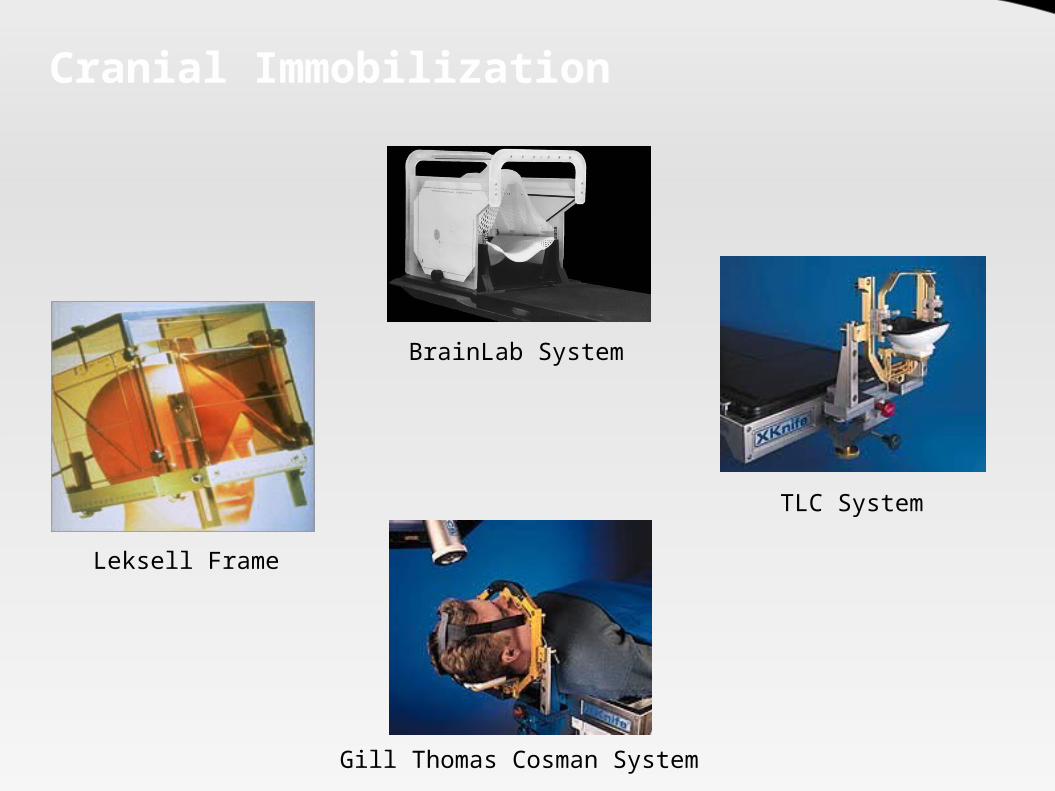
Cranial Immobilization
BrainLab System
TLC System
Gill Thomas Cosman System
Leksell Frame

Extracranial Immobilization
Elekta Body Frame
Body Fix system
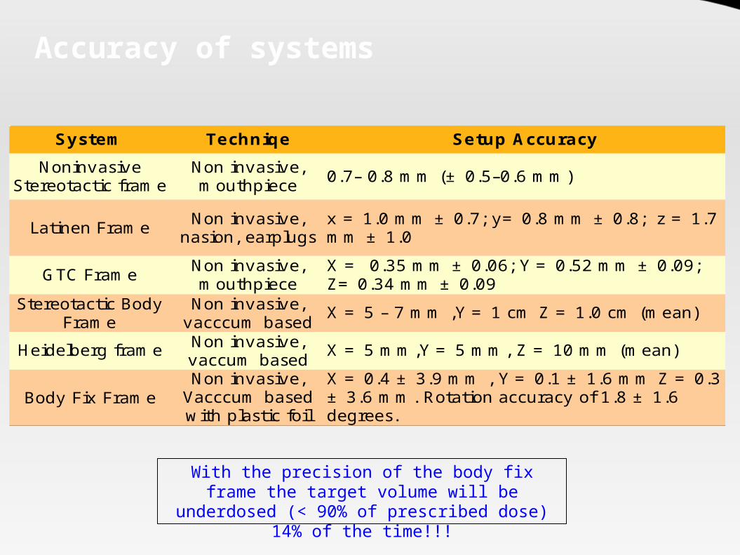
Accuracy of systems
System Techniqe Setup Accuracy
Latinen Frame
GTC Frame
X = 5 – 7 mm ,Y = 1 cm Z = 1.0 cm (mean)
Heidelberg frame X = 5 mm,Y = 5 mm, Z = 10 mm (mean)
Body Fix Frame
Noninvasive Stereotactic frame
Non invasive, mouthpiece 0.7– 0.8 mm (± 0.5–0.6 mm)
Non invasive, nasion, earplugs
x = 1.0 mm ± 0.7; y= 0.8 mm ± 0.8; z = 1.7 mm ± 1.0
Non invasive, mouthpiece
X = 0.35 mm ± 0.06; Y = 0.52 mm ± 0.09; Z= 0.34 mm ± 0.09
Stereotactic Body Frame
Non invasive, vacccum basedNon invasive, vaccum basedNon invasive,
Vacccum based with plastic foil
X = 0.4 ± 3.9 mm , Y = 0.1 ± 1.6 mm Z = 0.3 ± 3.6 mm. Rotation accuracy of 1.8 ± 1.6 degrees.
With the precision of the body fix frame the target volume will be underdosed (< 90% of
prescribed dose) 14% of the time!!!
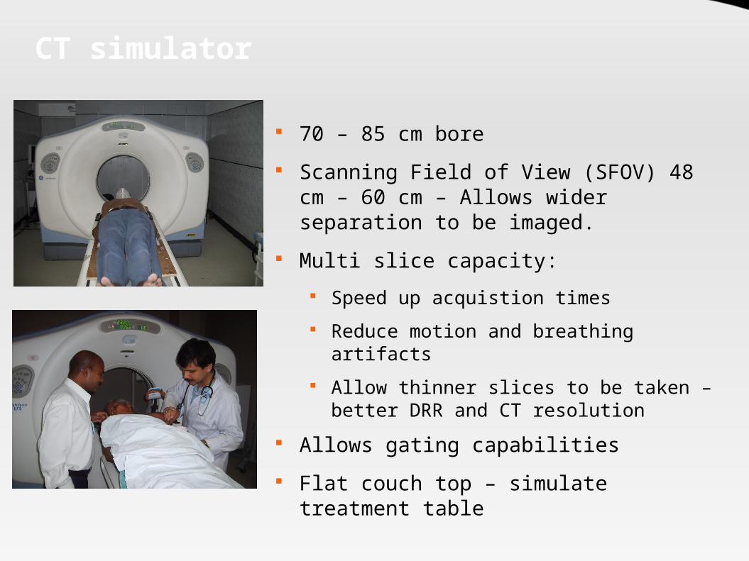
CT simulator
70 – 85 cm bore Scanning Field of View (SFOV) 48 cm –
60 cm – Allows wider separation to be imaged.
Multi slice capacity: Speed up acquistion times Reduce motion and breathing artifacts Allow thinner slices to be taken – better
DRR and CT resolution Allows gating capabilities Flat couch top – simulate treatment
table

MRI
Superior soft tissue resolution Ability to assess neural and marrow infiltration Ability to obtain images in any plane - coronal/saggital/axial Imaging of metabolic activity through MR Spectroscopy Imaging of tumor vasculature and blood supply using a new
technique – dynamic contrast enhanced MRI No radiation exposure to patient or personnel

PET: Principle
Unlike other imaging can biologically characterize a leison
Relies on detection of photons liberated by annhilation reaction of positron with electron
Photons are liberated at 180° angle and simultaneously – detection of this pair and subsequent mapping of the event of origin allows spatial localization
The detectors are arranged in an circular array around the patient
PET- CT scanners integrate both imaging modalities

PET-CT scanner
Flat couch top insert
CT Scanner
PET scanner
60 cm Allows hardware based registration as the patient is scanned in the
treatment position CT images can be used to provide attenuation correction factors for the
PET scan image reducing scanning time by upto 40%
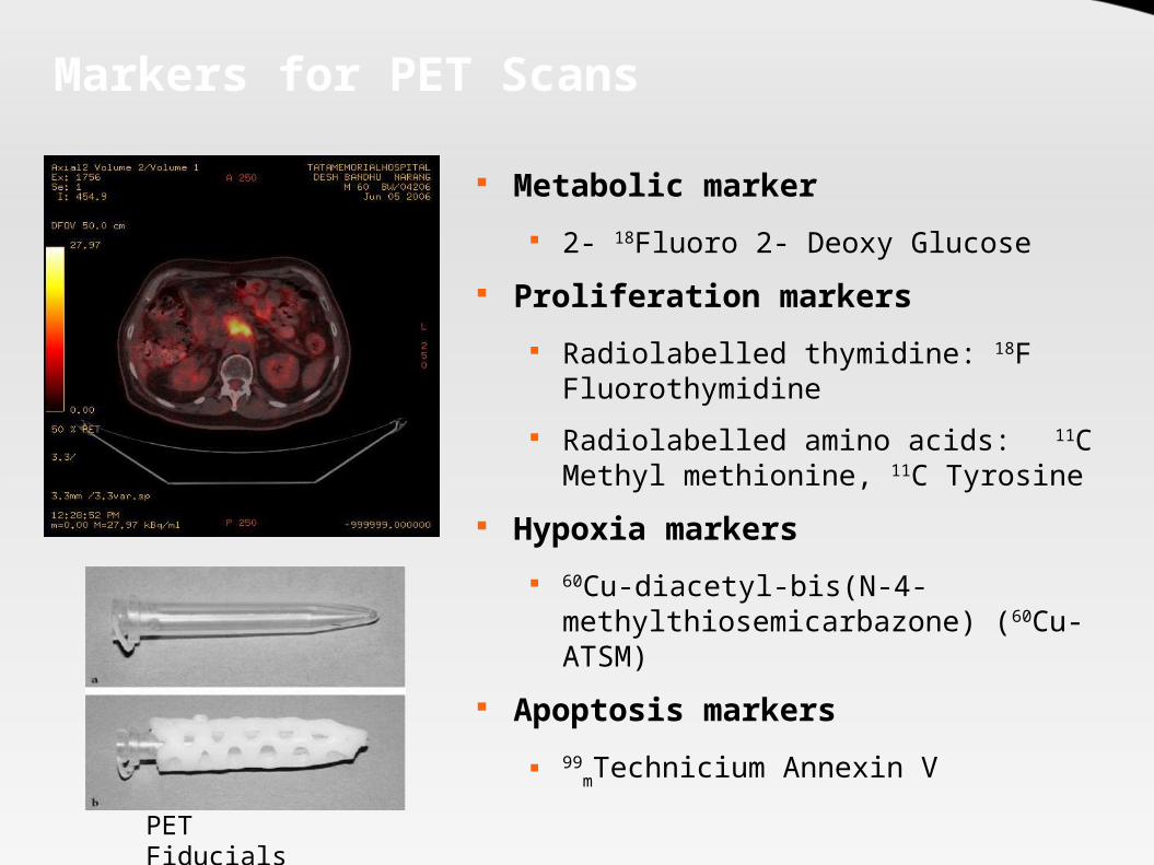
Markers for PET Scans
Metabolic marker 2- 18Fluoro 2- Deoxy Glucose
Proliferation markers Radiolabelled thymidine: 18F
Fluorothymidine Radiolabelled amino acids: 11C Methyl
methionine, 11C Tyrosine Hypoxia markers
60Cu-diacetyl-bis(N-4-methylthiosemicarbazone) (60Cu-ATSM)
Apoptosis markers 99
mTechnicium Annexin V
PET Fiducials

Image Registration
Technique by which the coordinates of identical points in two imaging data sets are determined and a set of transformations determined to map the coordinates of one image to another
Uses of Image registration: Study Organ Motion (4 D CT) Assess Tumor extent (PET / MRI fusion) Assess Changes in organ and tumor volumes over time
(Adaptive RT) Types of Transformations:
Rigid – Translations and Rotations Deformable – For motion studies

Concept

Process: Image Registration
The algorithm first measures the degree of mismatch between identical points in two images (metric).
The algorithm then determines a set of transformations that minimize this metric.
Optimization of this transformations with multiple iterations take place
After the transformation the images are “fused” - a display which contains relevant information from both images.

Image Registration

Target Volume delineation
The most important and most error prone step in radiotherapy.
Also called Image Segmentation The target volume is of following types:
GTV (Gross Target Volume) CTV (Clinical Target Volume) ITV (Internal Target Volume) PTV (Planning Target Volume)
Other volumes: Targeted Volume Irradiated Volume Biological Volume

Target Volumes
GTV: Macroscopic extent of the tumor as defined by radiological and clinical investigations.
CTV: The GTV together with the surrounding microscopic extension of the tumor constitutes the CTV. The CTV also includes the tumor bed of a R0 resection (no residual).
ITV (ICRU 62): The ITV encompasses the GTV/CTV with an additional margin to account for physiological movement of the tumor or organs. It is defined with respect to a internal reference – most commonly rigid bony skeleton.
PTV: A margin given to above to account for uncertainities in patient setup and beam adjustment.

Target Volumes

Definitions: ICRU 50/62GTV
CTV
ITV
PTV
TV
IV
Treated Volume: Volume of the tumor and surrounding normal tissue that is included in the isodose surface representing the irradiation dose proposed for the treatment (V95)
Irradiated Volume: Volume included in an isodose surface with a possible biological impact on the normal tissue encompassed in this volume. Choice of isodose depends on the biological end point in mind.

Example
PTV
CTV
GTV
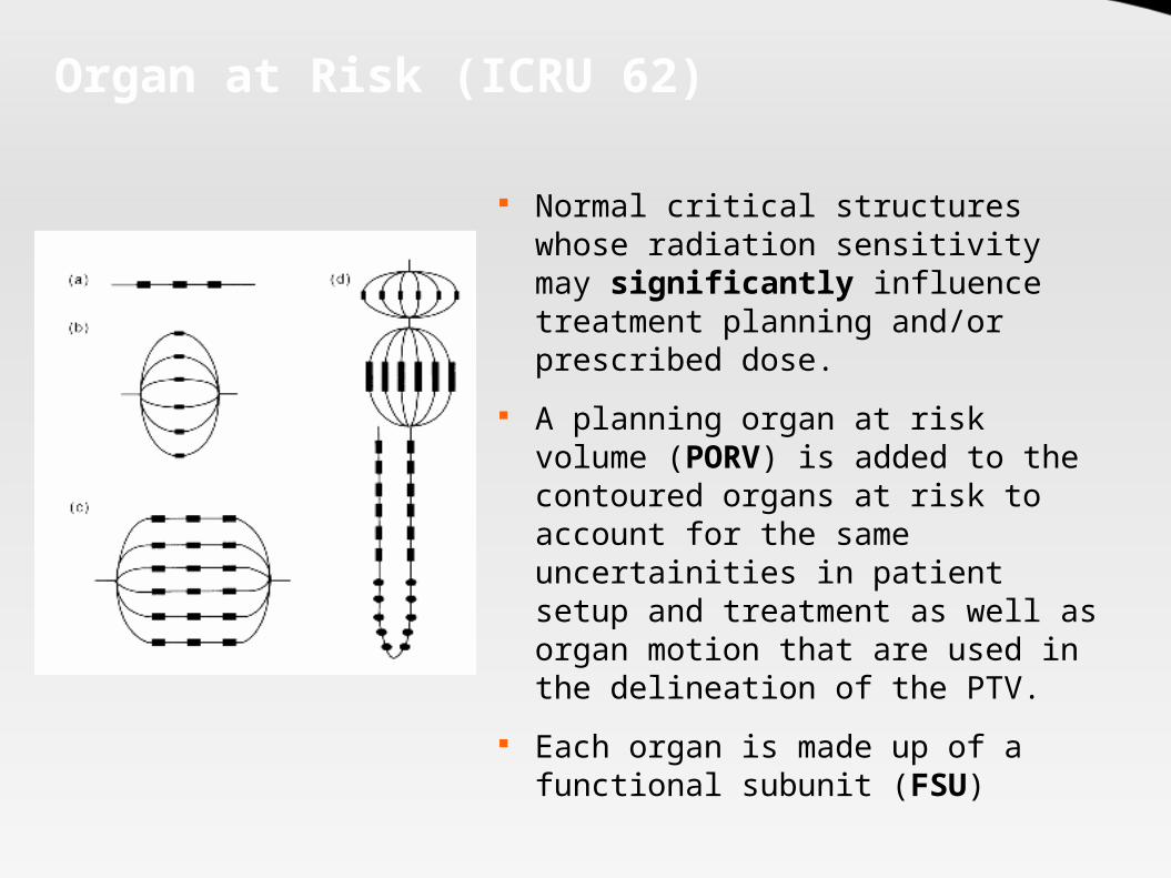
Organ at Risk (ICRU 62)
Normal critical structures whose radiation sensitivity may significantly influence treatment planning and/or prescribed dose.
A planning organ at risk volume (PORV) is added to the contoured organs at risk to account for the same uncertainities in patient setup and treatment as well as organ motion that are used in the delineation of the PTV.
Each organ is made up of a functional subunit (FSU)
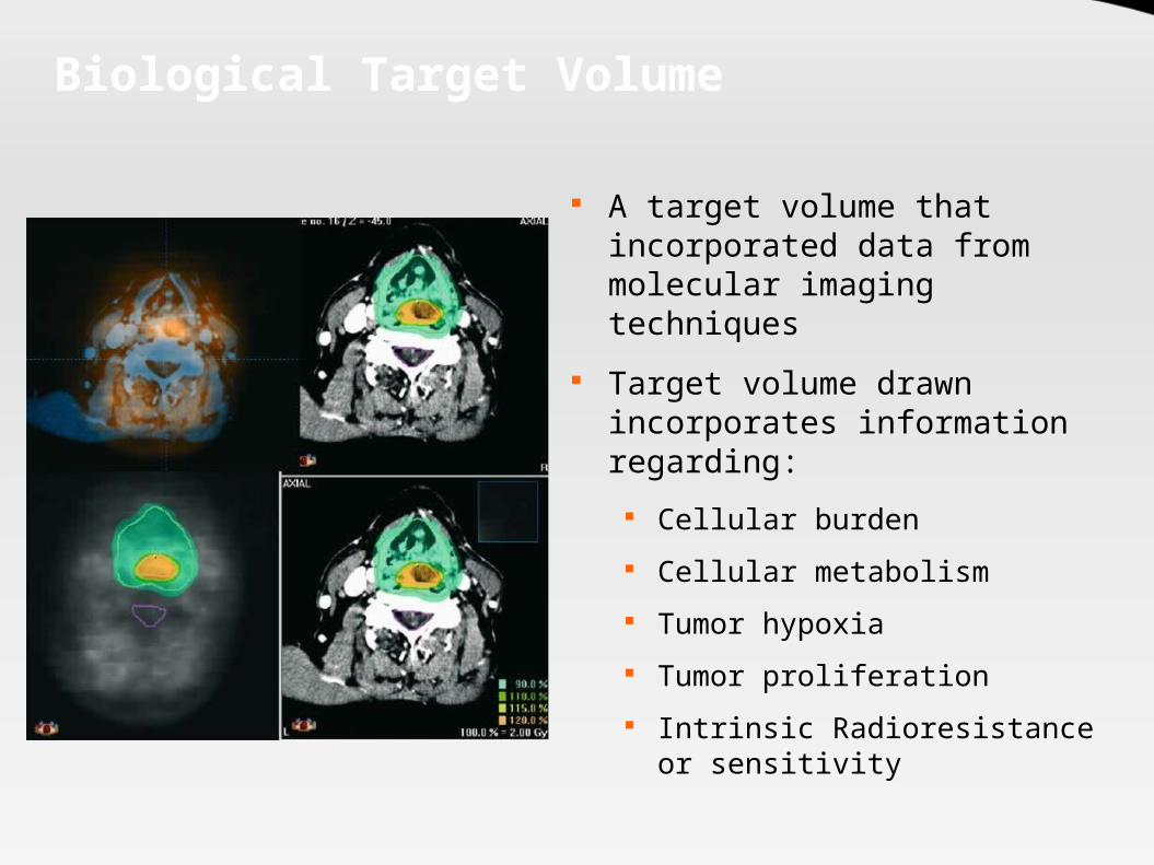
Biological Target Volume
A target volume that incorporated data from molecular imaging techniques
Target volume drawn incorporates information regarding:
Cellular burden Cellular metabolism Tumor hypoxia Tumor proliferation Intrinsic Radioresistance or
sensitivity

Biological Target Volumes
Lung Cancer: 30 -60% of all GTVs and PTVs are changed with PET. Increase in the volume can be seen in 20 -40%. Decrease in the volume in 20 – 30%. Several studies show significant improvement in nodal
delineation. Head and Neck Cancer:
PET fused images lead to a change in GTV volume in 79%. Can improve parotid sparing in 70% patients.

3 D TPS
Treatment planning systems are complex computer systems that help design radiation treatments and facilitate the calculation of patient doses.
Several vendors with varying characteristics Provide tools for:
Image registration Image segmentation: Manual and automated Virtual Simualtion Dose calculation Plan Evaluation Data Storage and transmission to console Treatment verification

Planning workflow
Define a dose objective
Total Dose
Total Time of delivery of dose
Total number of fractions
Choose Number of Beams
Choose beam angles and couch angles
Organ at risk dose levels
Choose Planning Technique
Forward Planning Inverse Planning

“Forward” Planning
A technique where the planner will try a variety of combinations of beam angles, couch angles, beam weights and beam modifying devices (e.g. wedges) to find a optimum dose distribution.
Iterations are done manually till the optimum solution is reached.
Choice for some situations: Small number of fields: 4 or less. Convex dose distribution required. Conventional dose distribution desired. Conformity of high dose region is a less important concern.

Planning Beams
Beams Eye View Display
Room's Eye View
Digital Composite Radiograph
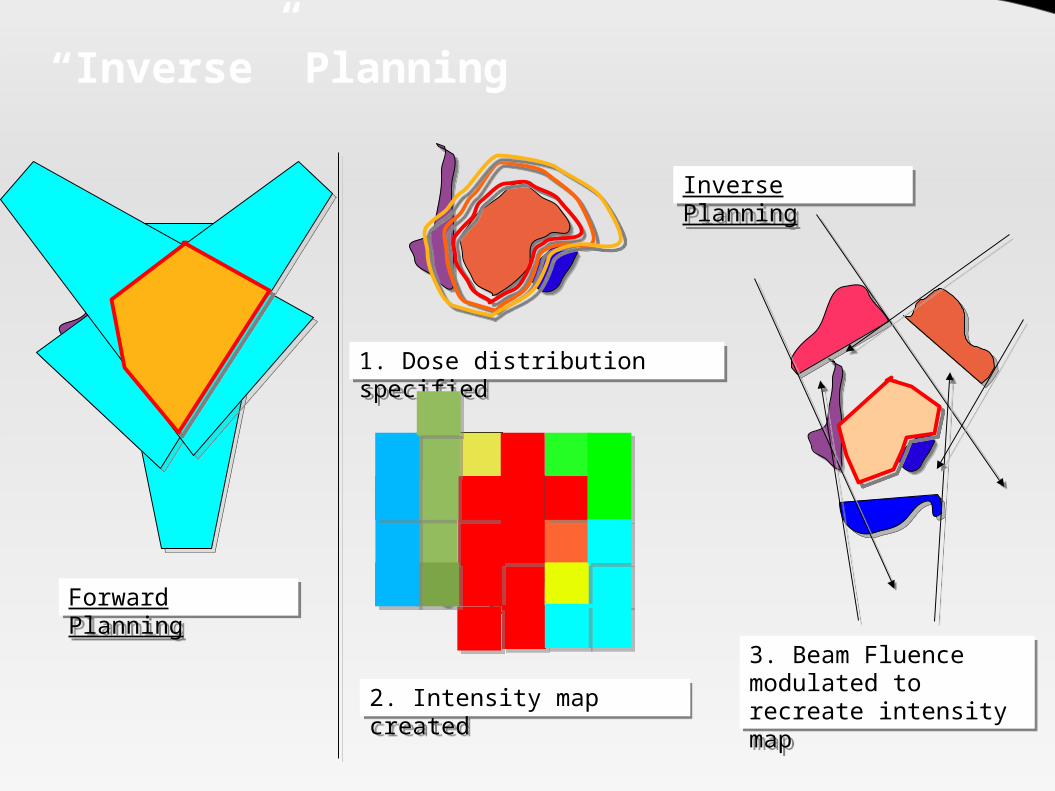
“Inverse” Planning
1. Dose distribution specified
Forward Planning
2. Intensity map created3. Beam Fluence modulated to recreate intensity map
Inverse Planning

Optimization
Refers to the technique of finding the best physical and technically possible treatment plan to fulfill the specified physical and clinical criteria.
A mathematical technique that aims to maximize (or minimize) a score under certain constraints.
It is one of the most commonly used techniques for inverse planning.
Variables that may be optimized: Intensity maps Number of beams Number of intensity levels Beam angles Beam energy

Optimization

Optimization Criteria
Refers to the constraints that need to be fulfilled during the planning process
Types: Physical Optimization Criteria: Based on physical dose coverage Biological Optimization Criteria: Based on TCP and NTCP
calculation A total objective function (score) is then derived from these
criteria. Priorities are defined to tell the algorithm the relative
importance of the different planning objectives (penalties) The algorithm attempts to maximize the score based on the
criteria and penalties.

Multicriteria Optimization
Sliders for adjusting EUD
RectumBladder
Intestine
PTV GTV
DVH display
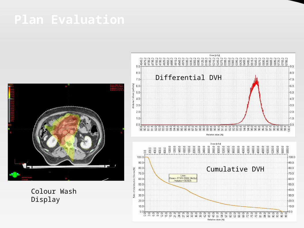
Plan Evaluation
Colour Wash Display
Differential DVH
Cumulative DVH
Image Guided Radiotherapy and 4D planning

Why 4D Planning?
Organ motion types: Interfraction motion Intrafraction motion
Even intracranial structures can move – 1.5 mm shift when patient goes from sitting to supine!!
Types of movement: Translations:
Craniocaudal Lateral Vertical
Rotations: Roll Pitch Yaw
Shape: Flattening Balloning Pulsation

Interfraction Motion
Prostate: Motion max in SI and AP SI 1.7 - 4.5 mm AP 1.5 – 4.1 mm Lateral 0.7 – 1.9 mm SV motion > Prostate
Uterus: SI: 7 mm AP : 4 mm
Cervix: SI: 4 mm
Rectum: Diameter: 3 – 46 mm Volumes: 20 – 40% In many studies decrease
in volume found Bladder:
Max transverse diameter mean 15 mm variation
SI displacement 15 mm Volume variation 20% -
50%

Intrafraction Motion
Liver: Normal Breathing: 10 – 25
mm Deep breathing: 37 – 55 mm
Kidney: Normal breathing: 11 -18 mm Deep Breathing: 14 -40 mm
Pancreas: Average 10 -30 mm
Lung: Quiet breathing
AP 2.4 ± 1.3 mm Lateral 2.4 ± 1.4 mm SI 3.9 ± 2.6 mm
2° to Cardiac motion: 9 ± 6 mm lateral motion
Tumors located close to the chest wall and in upper lobe show reduced interfraction motion.
Maximum motion is in tumors close to mediastinum
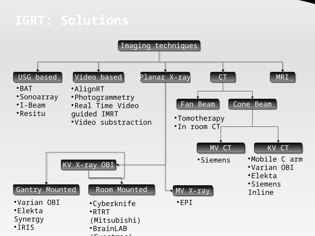
IGRT: SolutionsImaging techniques
USG based Video based Planar X-ray CT MRIBATSonoarrayI-BeamResitu
AlignRTPhotogrammetryReal Time Video guided IMRTVideo substraction
KV X-ray OBI
MV X-rayGantry Mounted Room MountedVarian OBIElekta SynergyIRIS
CyberknifeRTRT (Mitsubishi)BrainLAB (Exectrac)
EPI
Fan Beam Cone BeamTomotherapyIn room CT
MV CT KV CTSiemens Mobile C arm
Varian OBIElektaSiemens Inline

IGRT: Solution Comparision
DOF = degrees of freedom – directions in which motion can be corrected – 3 translations and 3 rotations

EPI
Uses of EPI: Correction of individual interfraction errors Estimation of poulation based setup errors Verification of dose distribution (QA)
Problems with EPI: Poor image quality (MV xray) Increased radiation dose to patient Planar Xray – 3 dimensional body movement is not seen Tumor is not tracked – surrogates like bony anatomy or
implanted fiducials are tracked.

Types of EPID
Liquid Matrix Ion Chamber* Camera based devices Amorphous silicon flat panel detectors Amorphous selenium flat panel detectors
Electrode connected to high voltage
“Output” electrodeLiquid 2,2,4 -
trimethylpentaneionized liquid
High voltage applied
Output read out by the lower electrodes

On board imaging
KV Xray
Intensifier
Room Mounted OBI
Gantry mounted OBI

4 D CT acqusitionAxial scans are acquired with the use of a RPM camera attached to couch.
The “cine” mode of the scanner is used to acquire multiple axial scans at predetermined phases of respiratory cycle for each couch position
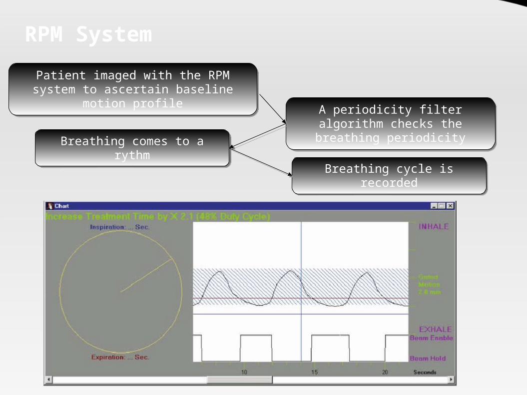
RPM System
Patient imaged with the RPM system to ascertain baseline motion profile
A periodicity filter algorithm checks the breathing periodicity
Breathing comes to a rythm
Breathing cycle is recorded

4D CT Data set
Normal

Problems with 4 D CT
The image quality depends on the reproducibility of the respiratory motion.
The volume of images produced is increased by a factor of 10.
Specialized software needed to sort and visualize the 4D data.
Dose delivered during the scans can increase 3-4 times. Image fusion with other modalities remains an unsolved
problem

4D Target delineation
Target delineation can be done on all images acquired. Methods of contouring:
Manual Automatic (Deformable Image Registration)
Why automatic contouring? Logistic Constraints: Time requirement for a single contouring
can be increased by a factor of ~ 10. Fundamental Constraints:
To calculate the cumulative dose delivered to the tumor during the treatment.
However the dose for each moving voxel needs to be integrated together for this to occur.
So an estimate of the individual voxel motion is needed.
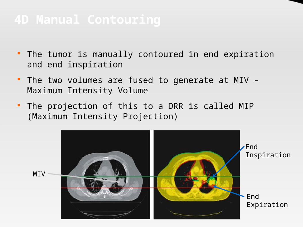
4D Manual Contouring
The tumor is manually contoured in end expiration and end inspiration
The two volumes are fused to generate at MIV – Maximum Intensity Volume
The projection of this to a DRR is called MIP (Maximum Intensity Projection)
End Expiration
End Inspiration
MIV

Automated Contouring
Technique by which a single moving voxel is matched on CT slices that are taken in different phases of respiration
The treatment is planned on a reference CT – usually the end expiration (for Lung)
Matching the voxels allows the dose to be visualized at each phase of respiration
Several algorithms under evaluation: Finite element method Optical flow technique Large deformation diffeomorphic image registration Splines thin plate and b

Automated Contouring
Movement vectors
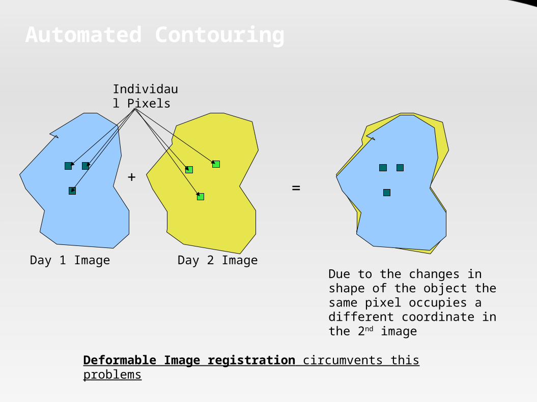
Automated Contouring
Day 1 Image Day 2 Image
Individaul Pixels
Due to the changes in shape of the object the same pixel occupies a different coordinate in the 2nd image
+ =
Deformable Image registration circumvents this problems
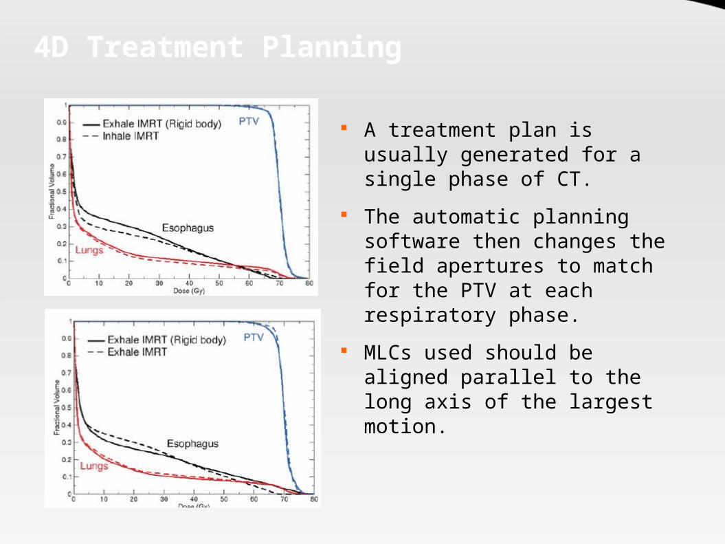
4D Treatment Planning
A treatment plan is usually generated for a single phase of CT.
The automatic planning software then changes the field apertures to match for the PTV at each respiratory phase.
MLCs used should be aligned parallel to the long axis of the largest motion.

Limitations of 4D Planning
Computing resource intensive – Parallel calculations require computer clusters at present
No commercial TPS allows 4 D dose calculation Respiratory motion is unpredictable – calculated dose good
for a certain pattern only Incorporating respiratory motion in dynamic IMRT means
MLC motion parameters become important constraints Tumor tracking is needed for delivery if true potential is to
be realized The time delay for dMLC response to a detected motion
means that even with tracking gating is important
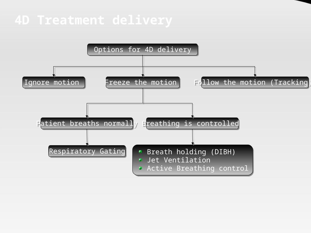
4D Treatment delivery
Options for 4D delivery
Ignore motion Freeze the motion Follow the motion (Tracking)
Patient breaths normally Breathing is controlled
Respiratory Gating Breath holding (DIBH)Jet VentilationActive Breathing control

Minimizing Organ Motion
Abdominal Compression(Hof et al. 2003 – Lung tumors):
Cranio-caudal movement of tumor 5.1±2.4 mm.
Lateral movement 2.6±1.4 Anterior-posterior
movement 3.1±1.5 mm
Breath Hold technique: Patients instructed to hold
breath in one phase Usually 10 -13 breath holding
sessions tolerated (each 12 -16 sec)
Reduced lung density in irradiated area – reduced volume of lung exposed to high dose
Tumor motion restricted to 2-3 mm (Onishi et al 2003 – Lung tumors)

Minimizing Organ Motion
Active Breathing Control Consists of a spirometer to “actively” suspend the patients
breathing at a predetermined postion in the respiratory cycle A valve holds the respiratory cycle at a particular phase of
respiration Breath hold duration : 15 -30 sec Usually immobilized at moderate DIBH (Deep Inspiration Breath
Hold) – 75% of the max inspiratory capacity Max experience: Breast Intrafractional lung motion reduced Mean reproducibility 1.6 mm

Tracking Target motion
Also known as Real-time Postion Management respiratory tracking system (RPM)
Various systems: Video camera based tracking (external) Radiological tracking:
Implanted fiducials Direct tracking of tumor mass
Non radiographic tracking: Implanted radiofrequncy coils (tracked magnetically) Implanted wireless transponders (tracked using wireless signals) 3-D USG based tracking (earlier BAT system)
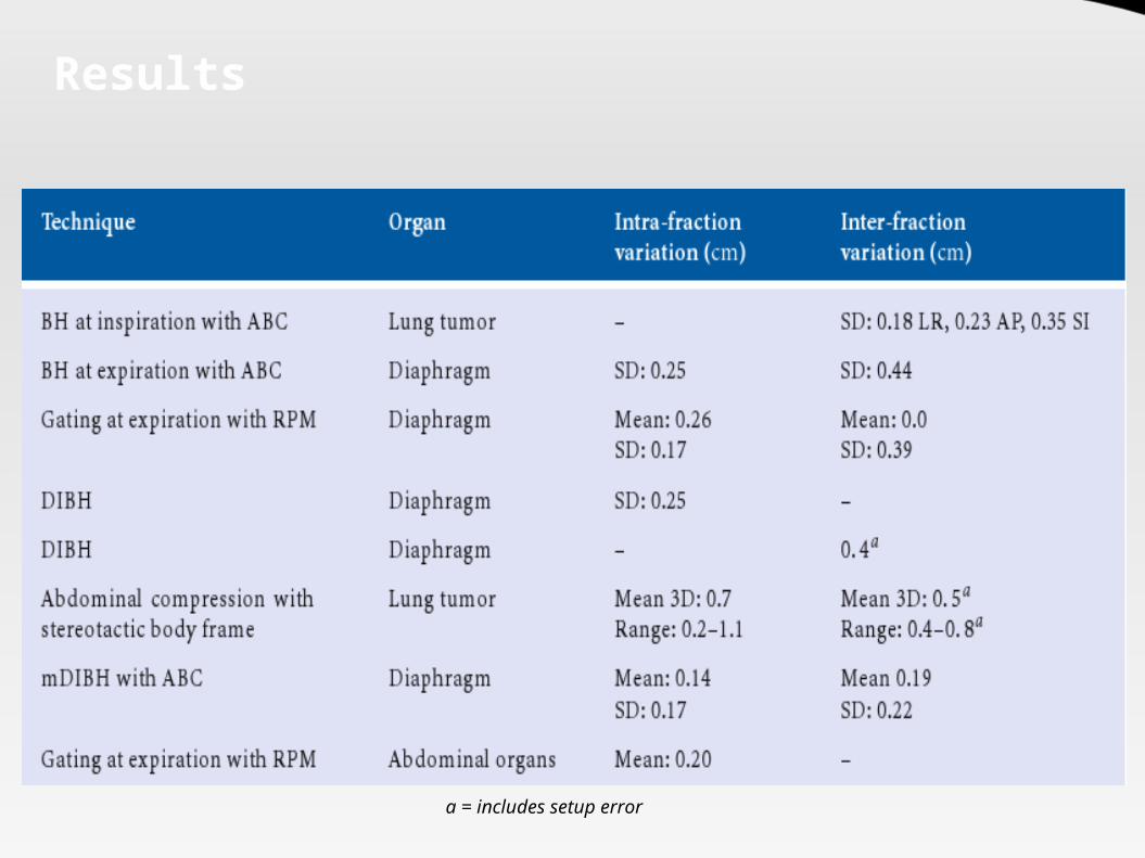
Results
a = includes setup error

Adaptive Radiotherapy Planning

Adaptive Radiotherapy (ART)
Adaptive radiotherapy is a technique by which a conformal radiation dose plan is modified to conform to a mobile and deformable target.
Two components: Adapt to tumor motion (IGRT) Adapt to tumor / organ deformation and volume change.
4 ways to adapt radiation beam to tracked tumor motion: Move couch electronically to adapt to the moving tumor Move a charged particle beam electromagnetically Move a robotic lightweight linear accelerator Move aperture shaped by a dynamic MLC

ART: Concept
Conventional RxSample Population based margins Accomadates variations of setup for the populationsNo or infrequent imagingLargest margin
Offline ARTIndividual patient based marginsFrequent imaging of patientsEstimated systemic error corrected based on repeated measurementsA small margin kept for random errorPlans adapted to average changes
Online ARTIndividual patient based marginsDaily imaging of patientsDaily error corrected prior to the treatmentSmallest margin requiredPlans adapted to the changing anatomy daily!
1. 2. 3.

ART: Why ?
Due to a change in the contours (e.g. Weight Loss) the actual dose received by the organ can vary significantly
from the planned dose despite accurate setup and lack of motion.

ART: Problem
Real time adaptive RT is not possible “today”
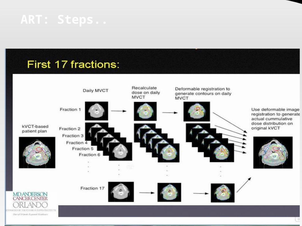
ART: Steps..
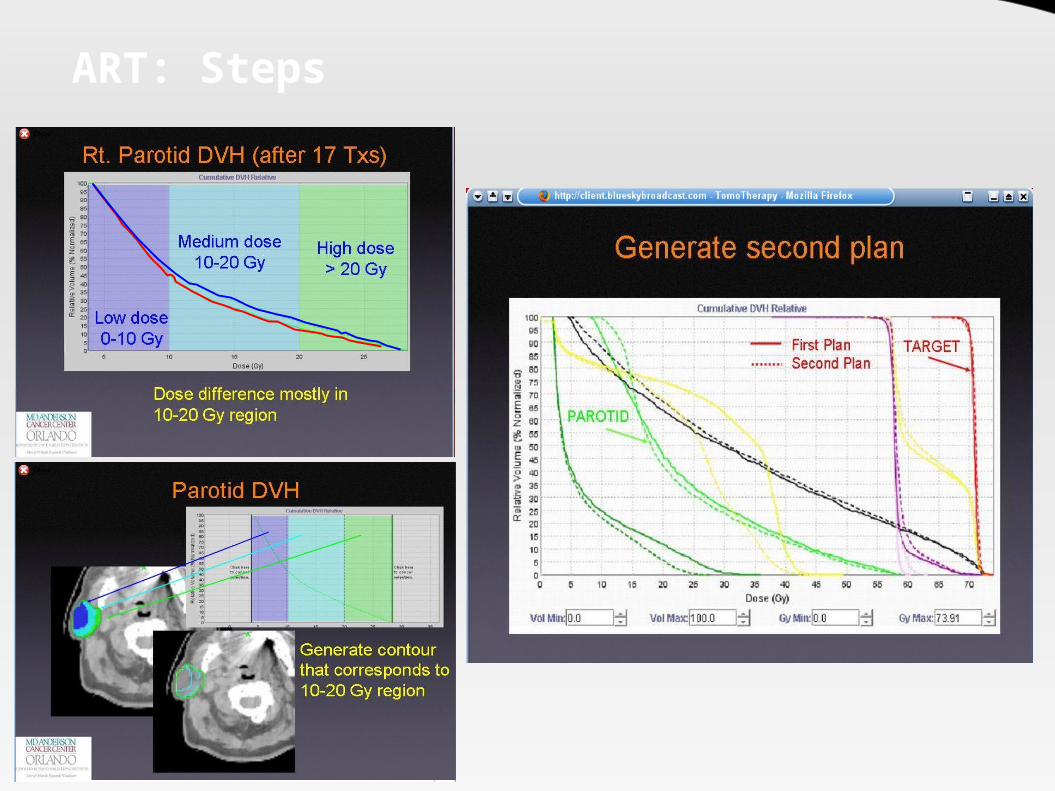
ART: Steps

Helical Tomotherapy

Helical Tomotherapy
Gantry dia 85 cm Integrated S Band LINAC 6 MV photon beam No flattening filter – output
increased to 8 Gy/min at center of bore
Independant Y - Jaws are provided (95% Tungsten)
Fan beam from the jaws can have thickness of 1 -5 cm along the Y axis

Helical Tomotherapy
Binary MLCs are provided – 2 positions – open or closed
Pneumatically driven 64 leaves Open close time of 20 ms Width 6.25 mm at isocenter 10 cm thick Interleaf transmission – 0.5% in
field and 0.25% out field Maximum FOV = 40 cm However Targets of 60 cm dia
meter can be treated.
LINAC
Cone Beam
Y jaw
Y jaw
Fan Beam
Binary MLC

Helical Tomotherapy
Flat Couch provided allows automatic translations during treatment
Target Length long as 160 cm can be treated
“Cobra action” of the couch limits the length treatable
Manual lateral couch translations possible
Automatic longitudinal and vertical motions possible

Helical Tomotherapy
Integrated MV CT obtained by an integrated CT detector array.
MV beam produced with 3.5 MV photons Allows accurate setup and image guidance Allows higher image resolution than cone
beam MV CT (3 cm dia with 3% contrast difference)
Tissue heterogenity calculations can be done reliably on the CT images as scatter is less (HU more reliable per pixel)
Not affected by High Z materials (implant) Dose 0.3 – 3 Gy depending on slice thickness Dose verification possible
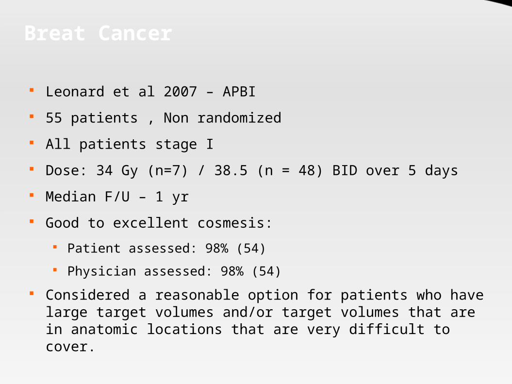
Breat Cancer
Leonard et al 2007 – APBI 55 patients , Non randomized All patients stage I Dose: 34 Gy (n=7) / 38.5 (n = 48) BID over 5 days Median F/U – 1 yr Good to excellent cosmesis:
Patient assessed: 98% (54) Physician assessed: 98% (54)
Considered a reasonable option for patients who have large target volumes and/or target volumes that are in anatomic locations that are very difficult to cover.

Lung Cancer
Author Year N CCT Dose Result2005 37 (I) Yes 63 Gy (median)
2005 No
2006 28 (I) No
2006 17 (I) Yes
2007 17 (I) 66 Gy
2007 Yes
Yom et al (R, NR)
7% incidence of Gr III pneumonitis
Yorke et al (P, NR)
78 (3D)
Dose escalation (50.7 – 90 Gy);
22% incidence of Gr III pneumonitis above doses of 70
Gy.Videtec (R,
NR)50 Gy in 5 fraction
(SBRT)64% T1; 2.6% Gr II pneumonitis, no Gr III reactions; LC and OS at 1 yr 96.4% and 93% respectively
Scarbrough (R, NR)
71.2 Gy (69–73.5 Gy)
Mean age 70; 73% IIIB, FU 1 yr, No Gr III tox, 2 yr OS 66%
J ensen (P, NR
Yes (citux)
Patients no suited for CCRT. 1 Gr III esophagitis; 79% response (6
mo)Yom et al (R, NR)
68 (I), 222 (3D)
63 Gy (median); Dose > 60 Gy 84% (I), 63%
(3D)
60% stage IIIB, FU = 8 mo (median); Gr III pneumonitis 8%
(32% for 3D CRT); V20 35% (I) vs 38%(3D) (p = 0.001)
Table showing results of IMRT in Lung Cancer
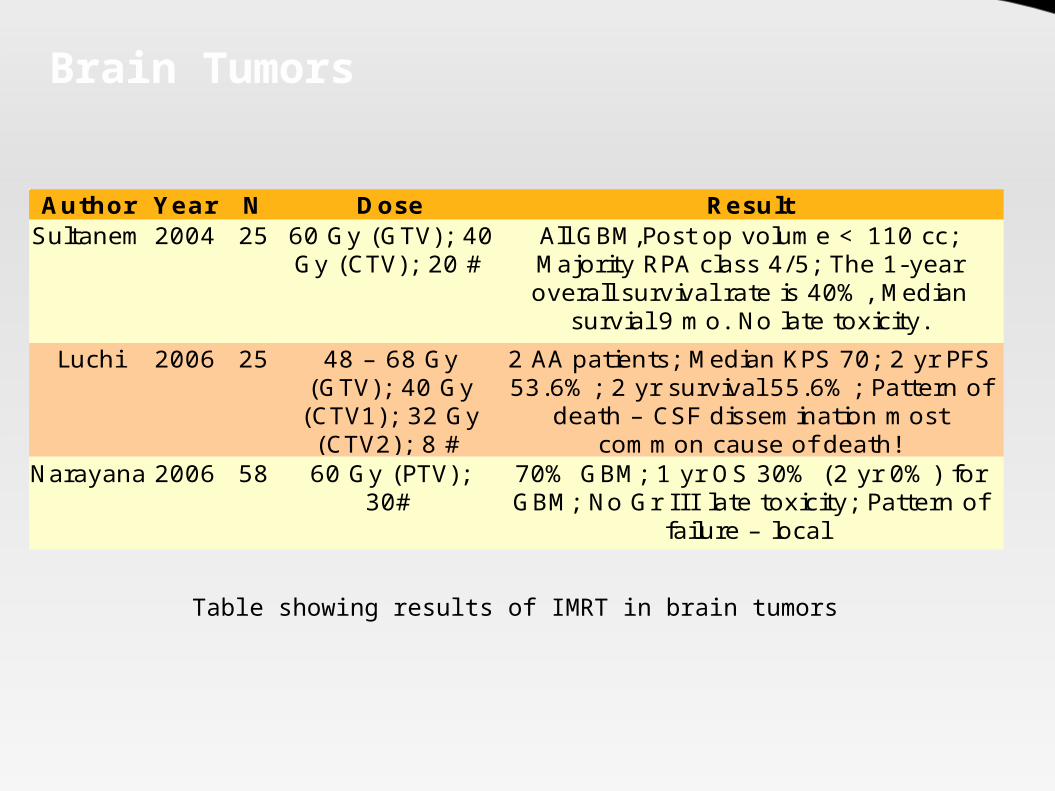
Brain Tumors
Author Year N Dose ResultSultanem 2004 25
Luchi 2006 25
Narayana 2006 58
60 Gy (GTV); 40 Gy (CTV); 20 #
All GBM,Post op volume < 110 cc; Majority RPA class 4/5; The 1-year overall survival rate is 40%, Median
survial 9 mo. No late toxicity.48 – 68 Gy
(GTV); 40 Gy (CTV1); 32 Gy (CTV2); 8 #
2 AA patients; Median KPS 70; 2 yr PFS 53.6%; 2 yr survival 55.6%; Pattern of
death – CSF dissemination most common cause of death!
60 Gy (PTV); 30#
70% GBM; 1 yr OS 30% (2 yr 0%) for GBM; No Gr I I I late toxicity; Pattern of
failure – local
Table showing results of IMRT in brain tumors

Cervical Cancer
Author Year N CCT Dose Result2003 36
2002 40 Y
2007 33 Y
2007 36 Y
Kochanski 2005 62
Mundt (P,NR)
Y (53%)
45 Gy (1.8 Gy/#)
80% stage I- II; PTV S3 to L4/5 interspace; Chronic GI toxicity 15% (n=
3; 1 Gr II, 2 Gr I); 50% incidence in Conventional
Mundt (P,NR)
45 Gy (1.8 Gy/#)
60% Acute Gr II toxicity (90% Gr II in Conv.); Less GU toxicity (10% vs 20%);
Patients not requiring antidiarrheal halved!
Chen (P,NR)
50.4 Gy / 28#
All Stage I - II; All Post Hysterectomy; 1 yr LRC 93%; Acute GI toxicity 36% (Gr I-
II); Acute Gu toxicity 30% (Gr I- II)Beriwal (P,NR)
45 Gy (EFRT) + 10-15 Gy
boost
2 Yr LC 80%; 2 yr OS 65%; 11 had recurrences – 9 distant; Gr III toxicity –
10%
Y (64%)
45 Gy (1.8 Gy /#)
29% Post op; 20 Stage IIB- IIIB; 3 yr DFS 72.7%; 3 yr pelvic control 87.5%; 5% Gr
II or higher late toxicity

Anal Canal
Author Year N CCT Dose Result2006 40 (I) Yes
2005 17 (I) Yes
2006 34 (I) Yes
2006 12 (I) Yes
Salama et al (R, NR)
45 Gy WP + 9 Gy boost
12.5% Gr III GI toxicity, 0 Gr III skin toxicity, 2 year colostomy-free, disease free, and overall survival 81%, 73%, and 86%
Milano et al (P, NR)
45 Gy WP + 9 Gy boost
53% Gr II GI toxicity, No Gr III acute or late complications. 82% CR rate, the 2-year CFS, PFS, and overall survial are: 82%,
65%, and 91%Devisetty
(P,NR)45 Gy WP + 9 Gy
boost17% Acute GI toxicity; volume of bowel receiving 22 Gy (V22) was correlated with toxicity (31.8%
acute GI toxicity for V22 > 563 cc vs. 0% for V22 ≤ 563 cc)
Hwang (P,NR)
30.6 Gy WP + 14.4 Gy Low Pelvic + 9 Gy
boost
42% Gr III dermal toxicity, 8% Gr III GI toxicity, 83% CR rate
New Techniques in Stereotactic Radiation therapy

Stereotaxy
Derived from the greek words Stereo = 3 dimensional space and Taxis = to arrange.
A method which defines a point in the patient’s body by using an external three-dimensional coordinate system which is rigidly attached to the patient.
Stereotactic radiotherapy uses this technique to position a target reference point, defined in the tumor, in the isocenter of the radiation machine (LINAC, gamma knife, etc.).
Units used: Gamma Knife LINAC with special collimators or mico MLC Cyberknife Neutron beams

Stereotactic Radiation
Two braod groups: Radiosurgery: Single
treatment fraction Radiotherapy: Multiple
fractions Frameless stereotactic
radiation is possible in one system – cyberknife
Sites used: Cranial Extracranial
Rigid application of a stereotactic frame to the patient
3 D Volumetric imaging with the frame attached
Target delineation and Treatment planning
Postioning of patinet with the frame after verification
QA of treatment and delivery of therapy

Sterotactic Radiation
The first machine used by Leksell in 1951 was a 250 KV Xray tube.
In 1968 the Gamma knife was available LINAC based stereotactic radiation appeared in 1980 Other machines using protons (1958) and heavy ions – He
(1978) were also used for stereotactic postioning of the Bragg's Peak

Gamma Knife
Designed to provide an overall treatment accuracy of 0.3 mm
3 basic components Spherical source housing 4 types of collimator
helmets Couch with electronic
controls 201 Co60 sources (30 Ci) Unit Center Point 40 cm Dose Rate 300 cGy/min

LINAC Radiosurgery
Conventional LINAC aperture modified by a tertiary collimator.
Two commercial machines Varian Trilogy Novalis

Cyberknife
Floor mounted Amorphous silicon detectors
6 MV LINAC
Roof mounted KV X-ray
Frameless patient immobilization couch
Robotic arm with 6 degrees of freedon
Circular Collimator attached to head
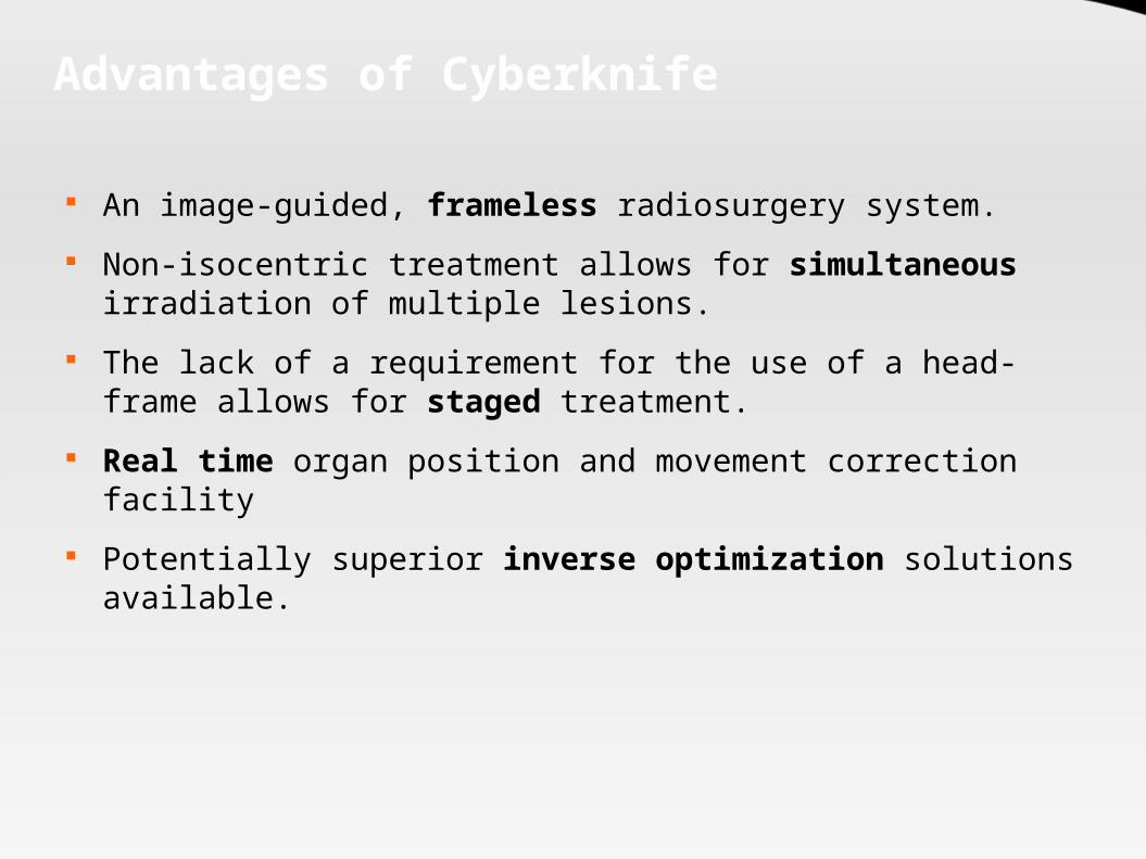
Advantages of Cyberknife
An image-guided, frameless radiosurgery system. Non-isocentric treatment allows for simultaneous
irradiation of multiple lesions. The lack of a requirement for the use of a head-frame allows
for staged treatment. Real time organ position and movement correction facility Potentially superior inverse optimization solutions
available.

Cyberknife
185 published articles till date; 5000 patients treated. 73 worldwide installations Areas where clinically evaluated:
Intracranial tumors Trigeminal neuralgia and AVMs Paraspinal tumors – 1° and 2° Juvenile Nasopharyngeal Angiofibroma Perioptic tumors Localized prostate cancer
However till date maximum expirence with Intracranial or Peri-spinal Stereotactic RT
Results
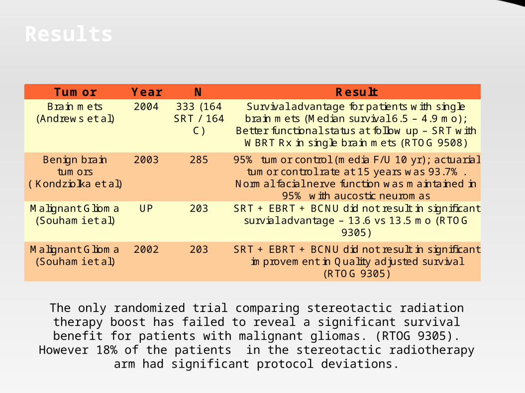
Tumor Year N Result2004
2003 285
UP 203
2002 203
Brain mets (Andrews et al)
333 (164 SRT / 164
C)
Survival advantage for patients with single brain mets (Median survival 6.5 – 4.9 mo);
Better functional status at follow up – SRT with WBRT Rx in single brain mets (RTOG 9508)
Benign brain tumors
( Kondziolka et al)
95% tumor control (media F/U 10 yr); actuarial tumor control rate at 15 years was 93.7%.
Normal facial nerve function was maintained in 95% with aucostic neuromas
Malignant Glioma (Souhami et al)
SRT + EBRT + BCNU did not result in significant survial advantage – 13.6 vs 13.5 mo (RTOG
9305)Malignant Glioma (Souhami et al)
SRT + EBRT + BCNU did not result in significant improvement in Quality adjusted survival
(RTOG 9305)
The only randomized trial comparing stereotactic radiation therapy boost has failed to reveal a significant survival benefit for patients with malignant
gliomas. (RTOG 9305). However 18% of the patients in the stereotactic radiotherapy arm had significant protocol deviations.
Related Documents