New processes for recovery of acetic acid from waste water Jignesh Gangadwala 1 , Gabriel Radulescu 1 , Achim Kienle 1,2* , Frank Steyer 1 , Kai Sundmacher 1,2 1 Max-Planck-Institute für Dynamik Komplexer Technischer Systeme, Sandtorstr. 1, D-39106 Magdeburg, Germany. 2 Otto-von-Guericke-Universität, D-39106 Magdeburg, Germany; fax: +49-391-6110515; e- mail: [email protected] . Abstract: This paper addresses an industrially important problem of acetic acid recovery from a waste water stream via reactive distillation. The presence of a three-phase regime on the column stages due to a liquid liquid phase split between aqueous and organic phases is a typical characteristic of this process. A modern modeling approach is presented to detect the existence of potential phase splitting in this column. A good agreement of a phase splitting model with the literature data has been shown. A theoretical study for the recovery of acetic acid from its 30 wt.% aqueous solution by esterification with n-butanol is presented. Alternate column structures were investigated and two structures rendering theoretically close to 100 % conversion of acetic acid were identified. The dynamic simulations were performed on proposed structures to see transient responses wrt. to common process disturbances. Keywords: phase splitting, homotopy continuation, reactive distillation, modeling and dynamic simulation, butyl acetate; esterification, acetic acid recovery 1. Introduction The recovery of dilute acetic acid from its aqueous stream is a major concern for many petrochemical and fine chemical industries. Conventional distillation process to complete this separation is highly uneconomical due to (a) the presence of a tangent pinch on the water end in the y-x diagram, that means high reflux ratio or high number of column stages to get pure products; and (b) large amount of water to be vaporized from dilute acid stream, which is impractical due to the high latent heat of vaporization of water. Recently, more advanced concepts based on azeotropic and extractive distillation have been proposed [3, 4]. Another very promising option is reactive distillation, where acetic acid is reacted off with a suitable alcohol in order to produce a valuable ester product at the one end and the aqueous stream free of organic impurities at the other end. In particular, esterification with n-butanol was proposed for this purpose [6]. In that work, however, by trial and error experiments maximum of up to 58 % acetic acid conversion was achieved with a 100 % excess of butanol in feed. In the present paper, using a model based approach, it can be observed that conversion close to 100 % is possible for such a process. Fig.-1 shows a typical RD column for the acetic acid recovery process. The interesting feature of this process is the potential phase split that can occur on many trays inside the column. To reliably predict the liquid – liquid phase split on the column trays in the course of a simulation run, an extra routine for the phase split calculations is required. The routine is based on homotopy continuation methods [1, 2, 7]. The complexity introduced by the liquid - * Corresponding author – Fax: +49-391-6110515; E-mail: [email protected] Page 1

Welcome message from author
This document is posted to help you gain knowledge. Please leave a comment to let me know what you think about it! Share it to your friends and learn new things together.
Transcript

New processes for recovery of acetic acid from waste water
Jignesh Gangadwala1, Gabriel Radulescu1, Achim Kienle1,2*, Frank Steyer1, Kai Sundmacher1,2
1Max-Planck-Institute für Dynamik Komplexer Technischer Systeme, Sandtorstr. 1, D-39106 Magdeburg, Germany. 2Otto-von-Guericke-Universität, D-39106 Magdeburg, Germany; fax: +49-391-6110515; e-mail: [email protected].
Abstract: This paper addresses an industrially important problem of acetic acid recovery from a waste water stream via reactive distillation. The presence of a three-phase regime on the column stages due to a liquid liquid phase split between aqueous and organic phases is a typical characteristic of this process. A modern modeling approach is presented to detect the existence of potential phase splitting in this column. A good agreement of a phase splitting model with the literature data has been shown. A theoretical study for the recovery of acetic acid from its 30 wt.% aqueous solution by esterification with n-butanol is presented. Alternate column structures were investigated and two structures rendering theoretically close to 100 % conversion of acetic acid were identified. The dynamic simulations were performed on proposed structures to see transient responses wrt. to common process disturbances. Keywords: phase splitting, homotopy continuation, reactive distillation, modeling and dynamic simulation, butyl acetate; esterification, acetic acid recovery
1. Introduction The recovery of dilute acetic acid from its aqueous stream is a major concern for many
petrochemical and fine chemical industries. Conventional distillation process to complete this separation is highly uneconomical due to (a) the presence of a tangent pinch on the water end in the y-x diagram, that means high reflux ratio or high number of column stages to get pure products; and (b) large amount of water to be vaporized from dilute acid stream, which is impractical due to the high latent heat of vaporization of water. Recently, more advanced concepts based on azeotropic and extractive distillation have been proposed [3, 4]. Another very promising option is reactive distillation, where acetic acid is reacted off with a suitable alcohol in order to produce a valuable ester product at the one end and the aqueous stream free of organic impurities at the other end. In particular, esterification with n-butanol was proposed for this purpose [6]. In that work, however, by trial and error experiments maximum of up to 58 % acetic acid conversion was achieved with a 100 % excess of butanol in feed. In the present paper, using a model based approach, it can be observed that conversion close to 100 % is possible for such a process.
Fig.-1 shows a typical RD column for the acetic acid recovery process. The interesting feature of this process is the potential phase split that can occur on many trays inside the column. To reliably predict the liquid – liquid phase split on the column trays in the course of a simulation run, an extra routine for the phase split calculations is required. The routine is based on homotopy continuation methods [1, 2, 7]. The complexity introduced by the liquid -
* Corresponding author – Fax: +49-391-6110515; E-mail: [email protected]
Page 1

liquid phase split besides the existing complexity of a reaction – separation interaction makes the analysis of this process very challenging.
Figure 1: A typical RD column for acid recovery The article is organized in the following way: first an appropriate model is presented that
carries out the simultaneous phase split calculations for a reactive distillation column. The model results showing a very good agreement with the literature data is presented afterwards. The phase split routine is used to design a heterogeneously catalyzed reactive distillation column for the acetic acid recovery process. The steady state simulation results are presented for the six alternate configurations generated based on physical insights. After the process screening based on the conversion levels, two process configurations are proposed. Next, dynamic simulation results are presented. At the end, conclusions and future directions are discussed.
2. Model summary The classical approach treats the RD process as a pseudo-homogeneous system, where no
phase splitting occurs in the liquid phase [8, 9]. However, for some systems, significant differences between states in the pseudo-homogeneous regime (no liquid phase splitting) and heterogeneous regime (with phase splitting) can be revealed [1, 2]. As consequence, an appropriate model has to be used in order to better reflect the real system behavior.
2.1. The new model structure As written in the open literature, taking into account the potential appearance of a second
liquid phase makes the dynamic simulation of the (reactive) distillation column a much more difficult task [1, 2, 7]. The main problems are the rapid, robust and reliable determination of the number of liquid phases and their composition on each tray during the simulation horizon managing in the same time switching in the process model when changes in the phase state on some trays occur. The model switching can be handled by considering that always there are two liquid phases present in the model and when the system leaves the heterogeneous regime, these two phases become identical having the same compositions. This way, there is no need
Page 2

to change the number of model equations when the system crosses the boundary between the homogeneous and heterogeneous region.
In this work, in order to improve the simulation robustness, a structural modeling approach was adopted, considering here two sections:
- the main model, relatively close to the “classical” RD model (without phase splitting), which calculates at each step the global composition in liquid (x) and vapor (y) phases, temperature (T), internal liquid (liq) and vapor (vap) streams flowrates, for all distillation stages (column trays and condenser + decanter);
- the phase splitting algorithm, externally carried out in a separate procedure, called by the main model at each step, for all distillation stages; this algorithm gets from the main model the global compositions (x) and temperatures (T), together with some other parameters, giving back both liquid phases compositions (x1 and x2) and ratios (Φ).
2.2. Modeling principles A. Main model The model assumptions are presented in the following. For a model validation section, a
a homogeneously catalyzed batch reactive distillation column model without energy balance; and for steady state and dynamic simulations, a continuous heterogeneously catalyzed reactive distillation column model with energy balances have been used. While the particular assumptions need to be presented for each specific case, the general ones are always valid – and so here they are:
1. All column trays and the decanter have constant liquid holdups. 2. The vapor holdup on trays is neglected. 3. The vapor and liquid phases are in equilibrium. 4. The reaction takes place only in the liquid phases. 5. The pressure drop along the column length was neglected. Here as example, the simple case of kth regular tray inside the column (as shown in Fig.-
2), for a homogeneously catalyzed process, with perfectly mixed reactants and catalyst, without considering the energy balance, is presented. The regular equations are:
Component material balance:
( ) ( ) ([ ] kk,NCk,1kk,NCk,1ki
kkkkk,ikk,ik
k,ikk,ik1k,i1k1k,i1kk,i
k
V2x,...,2xR1x,...,1xR1yfgabxflabzfgzufgzuzflzuflzu
yvapxliqyvapxliqdt
dxHOLD
⋅⋅Φ+⋅Φ−⋅ν+
+⋅−⋅−⋅+⋅+
+⋅−⋅−⋅+⋅= ++−−
)
i=1,…,NC – 1. (1)
Fig. 2. The kth tray inside RD column.
Page 3

It can be seen that a global reaction rate R is considered, as the linear combination between the reaction rate in phase 1 and the reaction rate in phase 2, taking into account the phases ratio Φk. If the liquid phase splitting does not occur, then the compositions in both phases are equal and the reaction rates are identical. As remark, such a linear expression [(1 – Φk) · R(x11,k,…,x1NC,k) + Φk · R(x21,k,…,x2NC,k)] can only be used when the uniform catalyst distribution in both liquid phases is considered.
Summation condition for global liquid phase compositions:
∑=
=NC
1jk,j 1x . (2)
Compositions in liquid phase 1 (externally calculated): PSA
i,ki,k 1x1x = , i=1,…,NC. (3) In this equation, represents the phase 1 composition, externally determined with the
“
PSAi,k1x
Phase Splitting Algorithm”. The same annotation, PSA, is attached for compositions in liquid phase 2 and phase ratio, also given by the same procedure:
Compositions in liquid phase 2(externally calculated): PSA
i,ki,k 2x2x = , i=1,…,NC. (4) Phase ratio (externally calculated):
PSAkk Φ=Φ . (5)
Phase equilibrium: kikiiki xpsppy ,,, 11 ⋅⋅=⋅ γ , i=1,…,NC. (6)
Summation condition for vapor phase compositions:
∑=
=NC
1jk,j 1y . (7)
Total material balance for the liquid phase:
( ) ( ) ([ ][ ]∑=
−
⋅⋅Φ+⋅Φ−⋅ν+
+−+−=NC
1jkk,NCk,1kk,NCk,1kj
kkk1k
V2x,...,2xR1x,...,1xR1
flabflzuliqliq0
) . (8)
Total material balance for the vapor phase: 1kk vapvap += . (9)
The models for the column top (condenser + decanter) and bottom (including the reboiler) are also based on the “core” equations above, with usual changes available in the literature describing these slightly modified structures.
The model to be used later for steady state and dynamic simulations as said before is a
heterogeneously catalyzed reactive disitllation column model with energy balances. This model has two major changes: 1. since the reaction kinetics are based on the activities (ai= xiγi) rather than the mole fractions, and since the activities in both the liquid phases are same when the liquid liquid phase split occurs assuming the phase equilibrium holds, for the global reaction rate calculation the phase split ratio need not to be taken in to account and assumption of uniform catalyst distribution will not be required. 2. energy balance equation replaces eq. 9 in the above model and eq. 8 needs to be modified to take the vapors inflows and outflows into consideration.
B. Phase splitting algorithm As mentioned before, the phase splitting algorithm runs almost independently, checking
at each step the state of all distillation stages and returning to the main model the phases
Page 4

compositions and ratios. Of course, before running, it takes some mandatory information from the main model, including overall compositions, stages temperatures and other needed parameters (i.e. for the vapor-liquid (-liquid) equilibrium calculation, also some algorithm “tuning parameters” – as starting points for the internal continuation algorithm, for instance – and so on).
The authors used in this work a phase splitting algorithm originally presented by Bausa and Marquardt [1], in the improved form proposed by Steyer, et al. [7]. It is a hybrid method using a-priori knowledge of phase diagram properties in order to tune-up the computational algorithm. The flash calculation is decomposed in two steps: a preprocessing step and the computational one.
In the first step, all heterogeneous regions of the system’s phase diagram at the specified pressure and boiling temperature are divided into convex regions and, for each region, one reference state inside it, (xSTART, x1START, x2START, ySTART, ΦSTART, pSTART, TSTART), is stored – denoting here the overall composition, compositions in both liquid phases, vapor composition, phase ratio, pressure and temperature. Typically, this analyzing procedure may be carried out only once, before simulations and more, since the phase diagrams are investigated in an early phase of the process design, the information on the heterogeneous region(s) existence may be directly provided by user (at least for mixture with up to four components).
In the next step, homotopy continuation is carried out starting at the known solution xSTART, x1START, x2START and ΦSTART) and ending at a desired two phase solution (x, x1, x2 and Φ) if it exist. The homotopy run can be parameterized by a continuation parameter λ in the following manner:
)()1( λλλ iSTARTiii xxxx =⋅−+⋅= , i=1,…,NC. (10)
λ is changed from 0 to 1 when the continuation is performed. It can be observed that STARTii x)0(x = and ii x)1(x = .
On its turn, the homotopy continuation algorithm is based on a repetitive two-step process. First one, the correction step, solves the following equations:
Mass balances (as constraints) )(2)1(1 λiii xxx =Φ⋅+Φ−⋅ , i=1,…,NC, (11)
Activity difference equations (as necessary conditions) 02211 =⋅−⋅ iiii xx γγ , i=1,…,NC, (12)
and The summation equation (as constraint)
∑=
=−NC
iix
1011 (or ). (13) ∑
=
=−NC
iix
1021
The above equations are written for the global composition x at a particular value for λ. A remark regarding the annotations: no tray index “k” is provided, in order to increase the readability.
In the second step (predictor step), a solution θ to equations (11), (12) and (13) for a new value of λ is estimated using
λ∆λθ
+θ=θ∆+θ=θ + dd m
s,mms,m1s,m , m=1,…,2NC+1, (14)
θm denoting an element of the solution vector. For the algorithm of Bausa and Marquardt [1], θ contains 2NC mole fractions (x1 and x2) and one phase ratio (Φ).
The algorithm works by alternating prediction and correction steps while increasing λ from 0 to 1, effectively moving along the binodal surface in an effort to reach the desired x composition.
Page 5

In systems with multiple binary pairs that exhibit phase splitting, multiple starting points for continuation have to be used in order to reach the correct solution [1]. This is due to the fact that the straight line according to equation (10) connecting the starting point xSTART with the desired composition x might cross over a region of one-phase behavior between the two-phase starting and ending points. As Bausa and Marquardt show in their paper, this approach is very successful in finding the correct solution very quickly, with a high reliability.
However, their original implementation has a big drawback: the solution vector θ has 2NC+1 components even if the system degree of freedom is NC!, increasing this way the computational time for the solver. This is why a modified method, developed by Steyer et al. [7] was used. The method’s principle is to parameterize the solution vector θ by introducing so-called phase partitioning coefficients, reducing the system order to NC, as the quoted authors proved in their work [7].
The correction step is based on Newton iteration, where the following equation system has to be solved:
)(f))(f(J ss1
s1s θ⋅θ−θ=θ −+ . (15)
In this equation, J denotes the Jacobian matrix of the remaining equation system (after model reduction), denoted here as f. To avoid inverting the Jacobian matrix, the equivalent linear equation system has to be solved. Also, for a fast and reliable solution, the authors suggest that the Jacobian should be computed analytically since the equation system is highly non-linear due to the activity coefficient model [7].
3. Model validation Due to the lack of comprehensive experimental data, the authors decided to validate their
model by reproducing the results of Brüggemann, et al. [2]. Their study is focused on a batch distillation process simulation in the heterogeneous regime, taking as example the laboratory column for butanol esterification to butyl acetate, previously presented by Venimadhavan, et al. [10].
Studying the column behavior, the quoted authors followed three operating strategies, for which they present results: a) ternary non-reactive distillation (loading the column still pot with a mixture of 40% water, 20% butanol and 40% butyl acetate, with no catalyst load), at a constant reflux ratio (0.9); b) reactive distillation (filling the still pot with a binary mixture of 51% butanol and 49% acetic acid), homogeneously catalyzed with sulfuric acid, at a constant reflux ratio (0.9); c) reactive distillation (filling the still pot with a binary mixture of 51% butanol and 49% acetic acid), homogeneously catalyzed with sulfuric acid, at a variable-adaptive reflux ratio (0.9 and 0.99).
In order to reproduce those scenarios, the model presented in this work was adapted for a 33 stage batch column, including the condenser + decanter and the still pot (with internal reboiler). At top, the external reflux (from decanter) comes on the first column tray. The holdup on each tray is 0.001kmol, the combined holdup of the condenser and decanter is 0.01kmol and the initial holdup of the still pot is 2kmol. Also, a constant vapor flowrate of 2kmol/h from the reboiler is considered. To maintain the consistency with Brüggemann’s work, the thermodynamic data and reaction kinetics were taken from Venimadhavan et al. [10].
All three operating strategies were investigated with our model implementation, but due to the lack of space only the results for the first one are here covered. Figures 3 and 4 depict the global composition in decanter and reboiler, respectively. On the left, the simulation time SIM_TIME is expressed in [seconds × 104], on the right, t is in [hours]. The right hand side picture is taken from Brüggemann, et al. [2].
Page 6

Fig. 3. Comparison between our model results (left) and literature results (right), – global
composition in decanter. After a close analysis, the authors concluded there is a perfect agreement between our
diagrams and those from the original Brüggemann’s paper, both for decanter and still pot, not only qualitatively-quantitatively, but also as timing, so the modeling approach in this work may be considered as valid and has to be put into value and tested for some other applications.
Fig. 4. Comparison between our model results (left) and literature results (right) – global
composition in still pot. 4. Alternate designs for acetic acid recovery by RD column The above-validated phase split routine is combined with a heterogeneously catalyzed
continuous reactive distillation column model from Gangadwala et al. [5] to design the acetic acid recovery process. In this section we present a few possible column configurations for the recovery process, some of this configurations are based on the work by Saha et al. [6]. The configurations 1 to 6 shown in Fig.-5 are obtained by changing the locations of aqueous and organic reflux from the decanter. For example, configuration 1 has no aqueous reflux and a total organic reflux is positioned at the top; configuration 2 on the other hand has no organic reflux and a total aqueous reflux is positioned at the top; configuration 3 has a total organic reflux and partial aqueous reflux at the top; configuration 4 has a partial organic and aqueous reflux; configuration 5 has a total aqueous reflux positioned at the reboiler and a partial organic reflux positioned at the top; and at last the configuration 6 has the reflux features similar to the configuration 5 but the feed is introduced into the two parts, i.e. dilute acetic acid feed at the top of the reaction zone and the pure alcohol feed at the bottom of the reaction zone. Obviously many other process variations are viable. The intention, here, is not to cover
Page 7
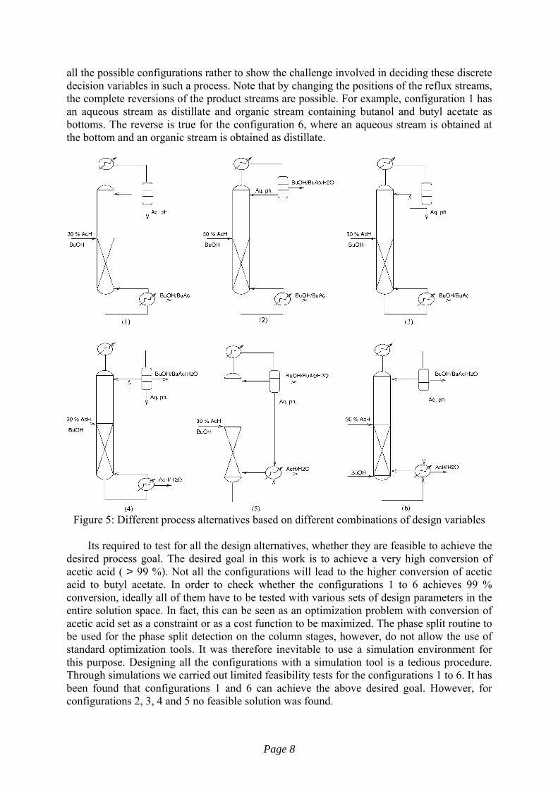
all the possible configurations rather to show the challenge involved in deciding these discrete decision variables in such a process. Note that by changing the positions of the reflux streams, the complete reversions of the product streams are possible. For example, configuration 1 has an aqueous stream as distillate and organic stream containing butanol and butyl acetate as bottoms. The reverse is true for the configuration 6, where an aqueous stream is obtained at the bottom and an organic stream is obtained as distillate.
Figure 5: Different process alternatives based on different combinations of design variables
Its required to test for all the design alternatives, whether they are feasible to achieve the
desired process goal. The desired goal in this work is to achieve a very high conversion of acetic acid ( > 99 %). Not all the configurations will lead to the higher conversion of acetic acid to butyl acetate. In order to check whether the configurations 1 to 6 achieves 99 % conversion, ideally all of them have to be tested with various sets of design parameters in the entire solution space. In fact, this can be seen as an optimization problem with conversion of acetic acid set as a constraint or as a cost function to be maximized. The phase split routine to be used for the phase split detection on the column stages, however, do not allow the use of standard optimization tools. It was therefore inevitable to use a simulation environment for this purpose. Designing all the configurations with a simulation tool is a tedious procedure. Through simulations we carried out limited feasibility tests for the configurations 1 to 6. It has been found that configurations 1 and 6 can achieve the above desired goal. However, for configurations 2, 3, 4 and 5 no feasible solution was found.
Page 8

Table 1: Feed compositions, BuOH:AcH is 2:1 configuration 6 configurations
1 to 5 Feed I Feed II Feed (Kmol/hr) 0.00675 0.0055 0.00125
Xach 0.0926 0.1137 0.0 XBuOH 0.1854 0.0 1.0 XbuAc 0.0 0.0 0.0 XH2O 0.7220 0.8863 0.0 XDBE 0.0 0.0 0.0
Characteristic simulation results of different configurations of Fig.-5 in a liquid-liquid
phase split regime are presented in Table 2. The feed compositions and feed flow rate are shown in Table 1. The molar ratio of butanol to acetic acid in the feed was considered to be 2:1, as recommended by Saha et al. [6]. Though it will be interesting to study the effect of the molar ratio in the feed, this is beyond the scope of the paper and will be considered in a separate work. As can be seen from the Table 2, the configurations 1 and 6 achieves 99 % conversion, configuration 5 achieves 92 % conversion and very little conversion levels are achieved by the other configurations. Due to numerical difficulties for the configuration 4 no steady state solution could be obtained. The other configurational details like number of column stages, reaction zone locations, feed stage locations, catalyst loading and reboiler duty requirement are also presented in Table 2. Configurations 1 and 6 require nearly the same reboiler heat duty to achieve 99 % conversion. The steady state composition profiles and profiles of a phase split ratio for configuration 1 and 6 can be seen from Fig.-6 (a) - (c) and Fig.-8 (a) - (c), respectively, as a start point for the dynamic simulation results.
Though configuration 1 and configuration 6 having very different column structures and reverse product streams, both are capable of providing close to 100 % conversion of acetic acid. Configuration 1 yields 99 % aqueous stream as a distillate and nearly a 50 – 50 mixture of butanol and butyl acetate as the bottoms. The downstream processing is required to separate the two organics. The configuration 6 yields a 98 % water stream at the bottom and organic stream containing 44 % BuAc, 26 % BuOH and 24 % water is obtained as a distillate. Significant amount of side product di-butyl ether is also present in the distillate stream. Here again a downstream processing step is required to produce a high purity acetate stream.
Table 2: Configurational details
Configurations 1 2 3 5 6 AcH conversion (%) 99 63.7 9.0 91.92 99
QR(kW) 0.1033 0.14 0.107 0.362 0.1244 Mcatst (kg/tray) 0.00265 6.90 0.0027 0.8381 1.3637
Nreac 8-21 12-21 12-21 12-21 9-21 Nstage 22 22 22 22 22
FTl 8th 11th 11th 11th 9th & 21st 5. Dynamic simulations for the proposed configurations
In this section, dynamic simulation results are presented for the base case steady states with 99 % conversion for configurations 1 and 6. Process responses are determined for ± 5 % step disturbances of the feed flow rate and the AcH composition in the feed.
Page 9

5.1 Configuration 1: The composition profiles shows a very high sensitivity to the disturbances for
configuration 1, as shown in Fig.-6. For instance, with an increase of 5 % in feed flowrate, these profiles moves like a traveling wave down in the stripping section leading to a serious drop in acetic acid conversion (from 99% to 38%, see Fig.-6 (d)). The system moves toward a new steady state with totally different composition profiles in the reactive zone. As it can be seen in Fig. 6 (a) and (b), the non-reactive zone above the feed tray remains unaffected. Fig.-6 (c) shows how the 3-phase regime extends from a small region around the feed tray to about 75% of the reactive zone, without any effect in the upper part of the column.
(a) (b)
(c) (d)
Figure 6: Transient response for configuration 1 to a 5 % increase in the feed flow rate:
(a) BuAc profile (b) H2O profile (c) phase fraction and (d) AcH conversion. (lightest gray line is a base case steady state with 99 % AcH conversion; intermediate gray lines show transient states and darkest gray line shows a final steady state)
The similar sensitivity was observed when feed flowrate was decreased by 5 %. The composition waves moved in a rectifying zone and the 3-phase regime observed to shrunken. At the new steady state conversion of acetic acid slightly increases as shown in Fig.-7 (a). Fig
Page 10
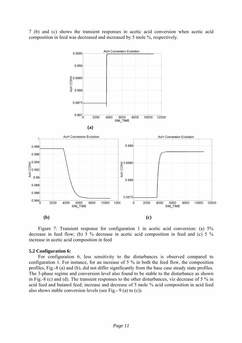
7 (b) and (c) shows the transient responses in acetic acid conversion when acetic acid composition in feed was decreased and increased by 5 mole %, respectively.
(a)
(b) (c)
Figure 7: Transient response for configuration 1 in acetic acid conversion: (a) 5% decrease in feed flow; (b) 5 % decrease in acetic acid composition in feed and (c) 5 % increase in acetic acid composition in feed 5.2 Configuration 6:
For configuration 6, less sensitivity to the disturbances is observed compared to configuration 1. For instance, for an increase of 5 % in both the feed flow, the composition profiles, Fig.-8 (a) and (b), did not differ significantly from the base case steady state profiles. The 3-phase regime and conversion level also found to be stable to the disturbance as shown in Fig.-8 (c) and (d). The transient responses to the other disturbances, viz decrease of 5 % in acid feed and butanol feed; increase and decrease of 5 mole % acid composition in acid feed also shows stable conversion levels (see Fig.- 9 (a) to (c)).
Page 11

(a) (b)
(c) (d)
Figure 8: Transient response for configuration 6 to 5 % increases in both the feed
flowrate: (a) BuAc profile (b) H2O profile (c) phase fraction and (d) AcH conversion. (lightest gray line is a base case steady state with 99 % AcH conversion; intermediate gray lines show transient states and darkest gray line shows a final steady state)
(a)
Page 12

(b) (c) Figure 9: Transient response for configuration 1 in acetic acid conversion: (a) 5%
decrease in both the feed flow; (b) 5 % decrease in acetic acid composition in acid feed and (c) 5 % increase in acetic acid composition in acid feed Conclusions
This work presented the new features characterizing a modern modeling approach for RD processes, which include phase splitting calculation. By adapting a rapid, robust and reliable algorithm based on homotopy-continuation method, the new model implementation was first validated and then put into value for a specific application, i.e. acetic acid recovery from the waste water. Two promising reactive distillation column structures were identified giving close to 100 % conversion of acetic acid to a valuable ester product. The intriguing process behaviors are revealed for the proposed column structures through a series of dynamic simulation runs – expansion and contraction of the three-phase regime along the column length is one of these phenomena, for example.
Important future directions are: (1) generating experimental data to validate the proposed model (2) integration of a reliable phase split routine within the standard optimization tool to obtain an economically optimal design (3) control of a desired steady state using some suitable control strategy.
Page 13

Nomenclature HOLD molar liquid holdup on tray J Jacobian matrix NC number of components R reaction ratio T temperature V volumetric liquid holdup on tray f function vector to be solved to 0 fgab vapor sidedraw molar flowrate fgzu external vapor feed molar flowrate flab liquid sidedraw molar flowrate flzu external liquid feed molar flowrate liq internal liquid molar flowrate p pressure psp saturation pressure in the vapor phase vap internal vapor molar flowrate x, x1, x2 mole fraction, liquid (global, phase 1, phase 2) y mole fraction, vapor phase zflzu mole fraction in external liquid feed zfgzu mole fraction in external vapor feed Greek letters Φ( or Fi) phase ratio γ1, γ2 activity coefficient (phase 1, phase 2) θ solution vector λ continuation parameter ν stoichiometric coefficient Superscripts CRIT critical point of the miscibility gap PSA value given by the Phase Splitting Algorithm START reference state (starting point for continuation) Subscripts A, B, C example states in the phase diagram k tray number i component indices m variable indices (in the solution vector) s current step
Page 14

REFERENCES 1. Bausa, J. and W. Marquardt (2000). Quick and reliable phase stability test in VLLE flash calculations by homotopy continuation. Computers and Chemical Engineering, 24, 2447 2456. 2. Brüggemann, S., J. Oldenburg, P. Zhang and W. Marquardt (2004). Robust Dynamic Simulation of Three-Phase Reactive Batch Distillation Columns. Industrial and Engineering Chemistry Research, 43, 3672-3684. 3. Chien I. L., K. L. Zeng, H. Y. Chao, and J. H. Liu (2004). Design and control of acetic acid dehydration system via heterogeneous azeotropic distillation. Chem. Engng. Sci., 59, 4547–4567. 4. Demiral H. and M. E. Yildirim (2003). Recovery of acetic acid from waste streams by extractive distillation. Water Sci. Technol., 47, 183–188. 5. Gangadwala J., A. Kienle, E. Stein, and S. Mahajani (2004). Production of butyl acetate by catalytic distillation: Process design studies. Ind. Eng. Chem. Res., 43:136 143. 6. Saha B., S. P. Chopade, and S. M. Mahajani (2000). Recovery of dilute acetic acid through eserification in a reactive distillation column. Catal. Today, 60, 147–157. 7. Steyer, F., D. Flockerzi and K. Sundmacher (2005). Equilibrium and rate-based approaches to liquid-liquid phase splitting calculations. Computers and Chemical Engineering, 30, 277-284. 8. Sundmacher, K. and A. Kienle (2002). Reactive Distillation – Status and Future Directions. Wiley-VCH, Weinheim. 9. Taylor, R. and R. Krishna (2000). Modeling reactive distillation. Chemical Engineering Science, 55, 5183-5229. 10. Venimadhavan, G., M. F. Malone and M. F. Doherty (1999). A Novel Distillate Policy for Batch Reactive Distillation with Application to the Production of Butyl Acetate. Industrial and Engineering Chemistry Research, 38, 714-722.
Page 15
Related Documents