New Multi-nodal Wireless Communication System Method ECG G 237 by Frank James A Thesis Presented in Partial Fulfillment of the Requirements for the Degree Master of Science Approved April 2014 by the Graduate Supervisory Committee: Dr. Martin Reisslein, Chair Dr. Lei Ying Dr. Yanchao Zhang ARIZONA STATE UNIVERSITY May 2014

Welcome message from author
This document is posted to help you gain knowledge. Please leave a comment to let me know what you think about it! Share it to your friends and learn new things together.
Transcript

New Multi-nodal Wireless Communication System Method
ECG G 237
by
Frank James
A Thesis Presented in Partial Fulfillment
of the Requirements for the Degree
Master of Science
Approved April 2014 by the
Graduate Supervisory Committee:
Dr. Martin Reisslein, Chair
Dr. Lei Ying
Dr. Yanchao Zhang
ARIZONA STATE UNIVERSITY
May 2014

i
ABSTRACT
The purpose of this paper is to introduce a new method of dividing wireless
communication (such as the 802.11a/b/g/n and cellular UMTS MAC protocols) across
multiple unreliable communication links (such as Ethernet). The purpose is to introduce
the appropriate hardware, software, and system architecture required to provide the basis
for a wireless system (using a 802.11a/b/g/n and cellular protocols as a model) that can
scale to support thousands of users simultaneously (say in a large office building, super
chain store, etc.) or in a small, but very dense communication RF region. Elements of
communication between a base station and a Mobile Station will be analyzed statistically
to demonstrate higher throughput, fewer collisions and lower bit error rates (BER) with
the given bandwidth defined by the 802.11n wireless specification (use of MIMO
channels will be evaluated). A new network nodal paradigm will be presented.
Alternative link layer communication techniques will be recommended and analyzed for
the affect on mobile devices. The analysis will describe how the algorithms used by state
machines implemented on Mobile Stations and Wi-Fi client devices will be influenced by
new base station transmission behavior. New hardware design techniques that can be
used to optimize this architecture as well as hardware design principles in regard to the
minimal hardware functional blocks required to support such a system design will be
described. Hardware design and verification simulation techniques to prove the hardware
design will accommodate an acceptable level of performance to meet the strict timing as
it relates to this new system architecture.

ii
ACKNOWLEDGMENTS
I would like to acknowledge Dr. Martin Reisslein for the opportunity to present this
thesis.
To those who have helped me over the many years that I have spend pursing higher
education. I cannot give back the lost time spent studying over long sleepless nights and
the lack of studious attention to the most important elements of life. Thank you.

iii
TABLE OF CONTENTS
Page
LIST OF TABLES ............................................................................................................. v
LIST OF FIGURES ............. ............................................................................................. vi
CHAPTER
1 INTRODUCTION ............. ............................................................................................. 1
WiFi Technology ....................................................................................... 1
Cellular Technology ................................................................................... 3
Cellular and WiFi System Comparison ..................................................... 5
2 PROPOSED WIRELESS SYSTEM DESIGN.............. ......................................... 12
Link Layer Communication Model ......................................................... 16
Cellular Link Layer MAC........................................................................ 21
Link Layer Hardware ............................................................................... 27
Link Layer Software ................................................................................ 34
3 MOBILE & BASE STATION .............. .................................................................. 37
Wireless State Machines .......................................................................... 37
Finite State Machine Behavior ................................................................ 38
Roaming ................................................................................................... 41
Cellular Roaming ..................................................................................... 43
PSD Estimation ........................................................................................ 46
Factor and Factor Ranges ........................................................................ 49
Factors, Factor Levels, and Response Variables ..................................... 53
Welsh, Yule-Walker, Burg, Covariance, Mod. Covariance, Music ....... 56

iv
CHAPTER Page
JMP Results, Output Data ........................................................................ 74
JMP ANOVA, ONE-WAY, TWO-WAY, Results and Conclusions .... 76
4 SYSTEM DESIGN .............. .................................................................................... 82
Hardware Design And Verification ......................................................... 86
Hardware Simulation And Verification .................................................. 89
Hardware Performance Simulation ......................................................... 94
5 SUMMARY CONCLUSION .............. ................................................................... 96
REFERENCES....... .............................................................................................................. 98
APPENDIX
A MATLAB PROGRAM AMPLITUDE/PHASE/FREQUENCY ESTIMATOR…. 100
B MATLAB PROGRAM BURG PSD ESTIMATOR…. ………………………….. 104
C MATLAB PROGRAM BLACKMAN-TUKEY PSD ESTIMATOR…. …………108
D MATLAB PROGRAM COVARIANCE PSD ESTIMATOR…. …………………112
E MATLAB PROGRAM MODIFIED COVARIANCE PSD ESTIMATOR…. ……116
F MATLAB PROGRAM MUSIC PSD ESTIMATOR………………………... ……120
G MATLAB PROGRAM WELCH PSD ESTIMATOR…………...…………... ……124
H MATLAB PROGRAM YULE-WALKER PSD ESTIMATOR……………... ……128

v
LIST OF TABLES
Table Page
1. 802.11 Real-Time Messages ...................................................................................... 19
2. 802.11 Non-Real Time Messages .............................................................................. 20
3. Example Cellular UMTS Messages (Wikipedia, 2014) ............................................. 21
4. Sample Link Layer Feature List ................................................................................. 27
5. Input Signals for PSD Measurement Tests ................................................................. 53
6. Response Variables (Measured Results) ..................................................................... 53
7. Output Response Results (ANOVA) .......................................................................... 75

vi
LIST OF FIGURES
Figure Page
1. Overview of 802.11 Subsystems................................................................................... 3
2. Overview of Cellular Subsystems ................................................................................. 5
3. 802.11 MAC Layer Communication Note: No RTC/CTS handshake depicted in
diagram above. (Airstream, 2014) ................................................................................ 7
4. Proposed System Architecture .................................................................................... 14
5. Simplified System Topology ...................................................................................... 16
6. 802.11 Link Layer Subsystem Partition...................................................................... 18
7. Probe Response Exemplar .......................................................................................... 19
8. Example Inter-RAT Handover Setup (4G Source to 3G Target Network) (Barton,
2012) ........................................................................................................................... 22
9. Example of Inter-RAT Handoff Execution (4G Source to 3G Target Network)
(Barton, 2012) ............................................................................................................. 24
10. New Cellular Link Layer Topology With Combined 802.11 Subsystems ................. 25
11. HW State Machines in SoC Architecture ................................................................... 28
12. Use of Random Numbers in HW Data Path ............................................................... 33
13. Network Frame Headers that most be pre-populated on a per Flow basis ................. 35
14. Frame Format Examples ............................................................................................. 36
15. Cellular Cell Reselection Rule Evaluation Process .................................................... 38
16. LTE Handset (Basic State Machine Terminology)(ShareTechnote, 2013) ................ 40
17. Example of 802.11 Roaming Utilizing Cell Controller Concept ................................ 42
18. Example of Cellular Roaming Utilizing Cell Controller Concept .............................. 44
vii
Figure Page
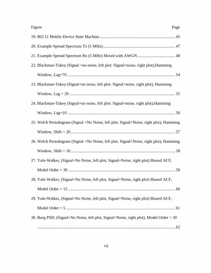
19. 802.11 Mobile Device State Machine ......................................................................... 45
20. Example Spread Spectrum Tx (5 MHz)...................................................................... 47
21. Example Spread Spectrum Rx (5 MHz) Mixed with AWGN .................................... 48
22. Blackman-Tukey (Signal +no noise, left plot: Signal+noise, right plot),Hamming
Window, Lag=70 ........................................................................................................ 54
23. Blackman-Tukey (Signal+no noise, left plot: Signal+noise, right plot), Hamming
Window, Lag = 20 ...................................................................................................... 55
24. Blackman-Tukey (Signal+no noise, left plot: Signal+noise, right plot),Hamming
Window, Lag=10 ........................................................................................................ 56
25. Welch Periodogram (Signal +No Noise, left plot, Signal+Noise, right plot), Hamming
Window, Shift = 20 ..................................................................................................... 57
26. Welch Periodogram (Signal +No Noise, left plot, Signal+Noise, right plot), Hamming
Window, Shift = 10 ..................................................................................................... 58
27. Yule-Walker, (Signal+No Noise, left plot, Signal+Noise, right plot) Biased ACF,
Model Order = 30 ....................................................................................................... 59
28. Yule-Walker, (Signal+No Noise, left plot, Signal+Noise, right plot) Biased ACF,
Model Order = 15 ....................................................................................................... 60
29. Yule-Walker, (Signal+No Noise, left plot, Signal+Noise, right plot) Biased ACF,
Model Order = 5 ......................................................................................................... 61
30. Burg PSD, (Signal+No Noise, left plot, Signal+Noise, right plot), Model Order = 30
..................................................................................................................................... 62

viii
Figure Page
31. Burg PSD, (Signal+No Noise, left plot, Signal+Noise, right plot), Model Order = 15
..................................................................................................................................... 63
32. Burg PSD, (Signal+No Noise, left plot, Signal+Noise, right plot), Model Order = 5
................................................................................................................................... ..63
33. Covariance, (Signal+No Noise, left plot, Signal+Noise, right plot) Model Order = 30
..................................................................................................................................... 65
34. Covariance, (Signal+No Noise, left plot, Signal+Noise, right plot) Model Order = 15
..................................................................................................................................... 66
35. Covariance, (Signal+No Noise, left plot, Signal+Noise, right plot) Model Order = 5.
..................................................................................................................................... 67
36. Modified Covariance, (Signal+No Noise, left plot, Signal+Noise, right plot), Model
Order = 30 ................................................................................................................... 68
37. Modified Covariance, (Signal+No Noise, left plot, Signal+Noise, right plot), Model
Order = 15 ................................................................................................................... 69
38. Modified Covariance, (Signal+No Noise, left plot, Signal+Noise, right plot), Model
Order = 5 ..................................................................................................................... 70
39. MUSIC PSD, (Signal+No Noise, left plot, Signal+Noise, right plot) Model Order =
30................................................................................................................................. 71
40. MUSIC PSD, (Signal+No Noise, left plot, Signal+Noise, right plot), Model Order =
15................................................................................................................................. 72
41. MUSIC PSD, (Signal+No Noise, left plot, Signal+Noise, right plot), Model Order = 5
..................................................................................................................................... 73

ix
Figure Page
42. Output Results (Response) Table................................................................................ 75
43. ANOVA analysis of output results (Plot 1: (L) Algorithm vs Mean & Plot 2: (R)
Resolution vs Mean) ................................................................................................... 76
44. ANOVA analysis of output results ((L) Algorithm vs Mean & (R) Resolution vs
Mean) .......................................................................................................................... 77
45. ANOVA analysis of output results ((L) Algorithm vs Mean & (R) Resolution vs
Mean) - Continued ...................................................................................................... 78
46. (2-Way ANOVA) Full Factorial ................................................................................. 79
47. Tukey HSD Means Test (Test for Interaction) ........................................................... 80
48. Packet Walkthrough on Example SoC, (Freescale, 2014) With Newly
Proposed/Designed Wireless Link Layer Capability .................................................. 84
49. Example of a HW Design/IP Verification and Unit Test Environment ...................... 92
50. Unit Co-Simulation Test Environment Ported to Real Silicon ................................... 93
51. HW Co-Simulation Environment that can be used to test HW Performance ............. 94

1
CHAPTER 1
INTRODUCTION
Wireless Technologies such as Wi-Fi and Cellular are converging in the market place.
This convergence promotes a need for link layer network technologies that better
facilitates the convergence of these technologies both from the radio frequency (RF)
modulation adaptation perspective as well as from the link layer protocol support
perspective. The following describes the two main wireless technologies and will lead a
discussion in regard to how the link layer protocols will support a new communication
process in reference to wireless communication.
Wi-Fi Technology
Background: Wi-Fi base stations (often referred to as Wi-Fi access points) are devices
that are deployed in disparate locations where RF coverage is needed; they are found in
houses, supermarkets, shops, and college campuses. Often these devices have memory, a
general purpose processor (GPP), a modem which is often comprised of a digital signal
processor, and HW such as a FPGA as well as RF hardware (e.g. filter, amplifier,
impedance circuit, antenna, etc…). Newer designs now have system on chip (SoC)
designs which combine the GPP with the DSP Intellectual Property (IP) technologies so
they provide a more integrated and smaller form factor solution. These designs, however,
require memory and an RF front end to support the receiver(s) and transmitter(s) and
additionally require a network interface for network access to the private network of the
service provide that interconnects with the Wide Area Network (WAN) wired for the
purpose of providing access to the Internet as well as management support interfaces so
that remote operation and maintenance (O&M) can be supported.
2
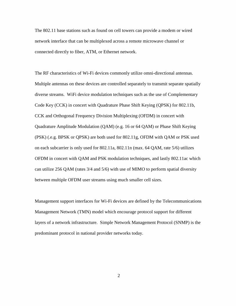
The 802.11 base stations such as found on cell towers can provide a modem or wired
network interface that can be multiplexed across a remote microwave channel or
connected directly to fiber, ATM, or Ethernet network.
The RF characteristics of Wi-Fi devices commonly utilize omni-directional antennas.
Multiple antennas on these devices are controlled separately to transmit separate spatially
diverse streams. WiFi device modulation techniques such as the use of Complementary
Code Key (CCK) in concert with Quadrature Phase Shift Keying (QPSK) for 802.11b,
CCK and Orthogonal Frequency Division Multiplexing (OFDM) in concert with
Quadrature Amplitude Modulation (QAM) (e.g. 16 or 64 QAM) or Phase Shift Keying
(PSK) (.e.g. BPSK or QPSK) are both used for 802.11g, OFDM with QAM or PSK used
on each subcarrier is only used for 802.11a, 802.11n (max. 64 QAM, rate 5/6) utilizes
OFDM in concert with QAM and PSK modulation techniques, and lastly 802.11ac which
can utilize 256 QAM (rates 3/4 and 5/6) with use of MIMO to perform spatial diversity
between multiple OFDM user streams using much smaller cell sizes.
Management support interfaces for Wi-Fi devices are defined by the Telecommunications
Management Network (TMN) model which encourage protocol support for different
layers of a network infrastructure. Simple Network Management Protocol (SNMP) is the
predominant protocol in national provider networks today.

3
Figure 1. Overview of 802.11 Subsystems
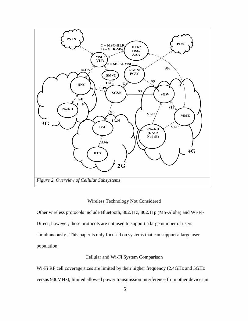
Cellular Technology
Background: Cellular base stations, as is the case with Wi-Fi base stations, are located
across the country in proximity to cellular towers. Often these towers are visible in close
proximity to interstates, highways, and neighborhoods; these towers are found
(sometimes camouflaged) in areas where RF coverage is needed. These towers are
commonly referred as “cell towers” and often are equipped with dipole antennas so as to
reduce impedance mismatch between the receiver and the antenna (impedance mismatch
causes Voltage Standing Wave Ratio (VSWR) which is a measure of reflected voltage)

4
that causes transmitter signal distortion. As is the case with Wi-Fi devices, these devices
have memory, a general purpose processor (GPP), a modem which is often comprised of
a digital signal processor and other hardware such as a FPGA. Newer designs now have
system on chip (SoC) designs which combine the GPP with the DSP technologies so they
require a smaller form factor. These designs, however, require memory and an RF front
end (e.g. filter, amplifier, impedance circuit(s) and antenna(s)) to support the receiver(s)
and transmitter(s) and additionally require management support interfaces so that remote
operation and maintenance (O&M) can be supported. Unlike Wi-Fi, these devices have
additional subsystems that manage roaming between many different cells across the
country. In addition, many transceivers are located at the same location. The common
modulation techniques used by cellular base stations are Gaussian Minimum Shift
Keying (GMSK) for Global System for Mobile Communications (GSM), that is data is
sent through a Gaussian filter before it is MSK modulated/demodulated, Code Division
Multiple Access (CDMA2000) in concert with PSK (e.g. BPSK, QPSK), WCDMA in
concert with PSK which is used for Universal Mobile Telecommunications System
(UMTS) systems. T-Mobile and AT&T utilize UMTS/GSM, while Verizon utilizes
CDMA2000 for voice transmissions while using LTE which uses Orthogonal Frequency
Multiple Access (OFDMA) in concert with PSK or QAM on each subcarrier for data
transmission. Cellular base stations often utilize dipole antennas that reduce the amount
of impedance mismatch found in 50 ohm coax connections between the antenna and the
RF front end. The RF front end is comprised of a high bandwidth filter(s), antenna(s),
impedance circuit(s), and amplifier(s).
5
Figure 2. Overview of Cellular Subsystems
Wireless Technology Not Considered
Other wireless protocols include Bluetooth, 802.11z, 802.11p (MS-Aloha) and Wi-Fi-
Direct; however, these protocols are not used to support a large number of users
simultaneously. This paper is only focused on systems that can support a large user
population.
Cellular and Wi-Fi System Comparison
Wi-Fi RF cell coverage sizes are limited by their higher frequency (2.4GHz and 5GHz
versus 900MHz), limited allowed power transmission interference from other devices in

6
this unlicensed band (though somewhat mitigated by its modulation technique), and more
importantly by their link layer communication specification. Unlike cellular
communication, Wi-Fi communication devices specify a link layer communication model
based upon a CSMA/CA format. The CSMA/CA format is not as effective multiple
access protocol as is the case with TDMA or CDMA technologies. Though Wi-Fi can
close links at longer distances, greater amplification and antenna directivity is required as
well as cooperative changes to the Wi-Fi link layer timing specifications. Example: DIFS
is the amount of time a station must sense a clear radio before beginning a new
transmission sequence. Note that a node can format and buffer a data frame to be
transmitted during this time interval. SIFS is the amount of time a station must wait
before sending or beginning to receive a RTS, CTS or ACK frame, note that the SIFS
time includes the amount of time to format the ACK frame to be transmitted; this is
possible since only the first portion of the data frame (e.g. BSSID) is used in the ACK
message. PIFS is the DIFS for the access point in a special access method known as
Point Coordination Function. The times are defined such that the RTS, CTS, and ACK
frames are given a higher priority (ie once a packet transmission sequence has begun, the
station holds onto the channel until it is finished). Without 802.11 RTS/CTS
handshaking the following time periods are observed.

7
Figure 3. 802.11 MAC Layer Communication Note: No
RTC/CTS handshake depicted in diagram above. (Airstream,
2014)
IEEE mandates the following timing for 802.11a:
Time Slot = 9 µs
SIFS = 16 µs
(1)
IEEE mandates the following timing for 802.11b:
Time Slot = 20 µs
SIFS = 10 µs
PIFS = SIFS + Time Slot = 30 µs
(2)
IEEE mandates the following timing for 802.11g:
Time Slot = 9 µs
SIFS = 10 µs
(3)

8
Sender procedure: Wait DIFS, Send Data, Wait SIFS, Listen for and receive ACK (until
maximum ACK timeout), Repeat
Receiver Procedure: Listen for and receive Data,Wait SIFS, Send ACK, Wait DIFS
Given this link layer communication protocol, the destination must start constructing the
ACK message once the first part of the data message has been received. Once it has been
determined that the data message was received without error, an ACK message may be
transmitted. The following is the timing calculation for sending the ACK message:
(4)
With the speed of light , a 802.11 ACK transmission can travel a distance
of 300 . Assuming a normal transmission of an ACK message, the receiver
could be no greater than 3 km (given the speed of light, a nice number) away or 10 usec.
If ACK timeout was increased (to say 19 usec), the maximum slot time for a point to
multi-point communication environment is equal to the slot time. For 802.11b the slot
time of 20 usec equates to a maximum distance of 6 km. Other wireless standards have
similar limitations but the distances are shorter.
Cellular requirements to address cellular reselection within greater cell sizes (> 1Km),
though is possible with some cellular protocols, requires special configuration of the
cellular chipsets to accomplish. 802.11, due to the CSMA/CA protocol requirements is
9
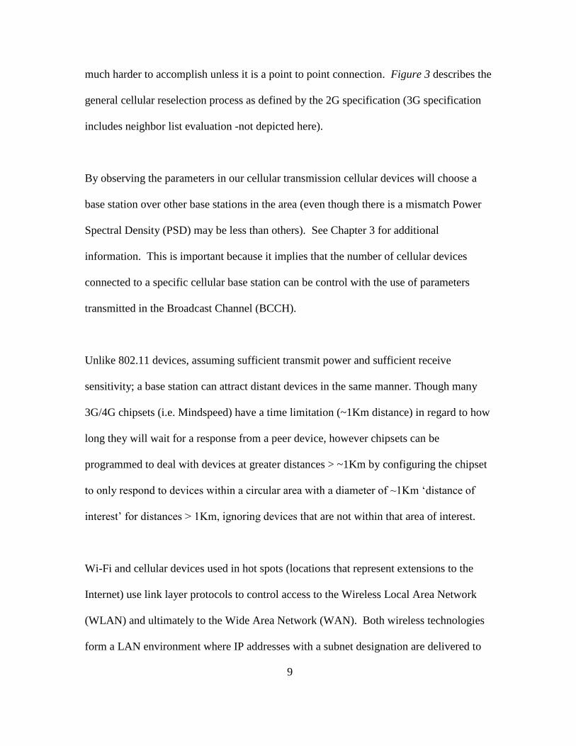
much harder to accomplish unless it is a point to point connection. Figure 3 describes the
general cellular reselection process as defined by the 2G specification (3G specification
includes neighbor list evaluation -not depicted here).
By observing the parameters in our cellular transmission cellular devices will choose a
base station over other base stations in the area (even though there is a mismatch Power
Spectral Density (PSD) may be less than others). See Chapter 3 for additional
information. This is important because it implies that the number of cellular devices
connected to a specific cellular base station can be control with the use of parameters
transmitted in the Broadcast Channel (BCCH).
Unlike 802.11 devices, assuming sufficient transmit power and sufficient receive
sensitivity; a base station can attract distant devices in the same manner. Though many
3G/4G chipsets (i.e. Mindspeed) have a time limitation (~1Km distance) in regard to how
long they will wait for a response from a peer device, however chipsets can be
programmed to deal with devices at greater distances > ~1Km by configuring the chipset
to only respond to devices within a circular area with a diameter of ~1Km ‘distance of
interest’ for distances > 1Km, ignoring devices that are not within that area of interest.
Wi-Fi and cellular devices used in hot spots (locations that represent extensions to the
Internet) use link layer protocols to control access to the Wireless Local Area Network
(WLAN) and ultimately to the Wide Area Network (WAN). Both wireless technologies
form a LAN environment where IP addresses with a subnet designation are delivered to
10
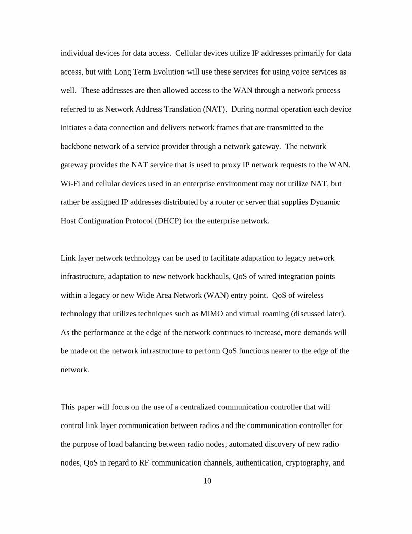
individual devices for data access. Cellular devices utilize IP addresses primarily for data
access, but with Long Term Evolution will use these services for using voice services as
well. These addresses are then allowed access to the WAN through a network process
referred to as Network Address Translation (NAT). During normal operation each device
initiates a data connection and delivers network frames that are transmitted to the
backbone network of a service provider through a network gateway. The network
gateway provides the NAT service that is used to proxy IP network requests to the WAN.
Wi-Fi and cellular devices used in an enterprise environment may not utilize NAT, but
rather be assigned IP addresses distributed by a router or server that supplies Dynamic
Host Configuration Protocol (DHCP) for the enterprise network.
Link layer network technology can be used to facilitate adaptation to legacy network
infrastructure, adaptation to new network backhauls, QoS of wired integration points
within a legacy or new Wide Area Network (WAN) entry point. QoS of wireless
technology that utilizes techniques such as MIMO and virtual roaming (discussed later).
As the performance at the edge of the network continues to increase, more demands will
be made on the network infrastructure to perform QoS functions nearer to the edge of the
network.
This paper will focus on the use of a centralized communication controller that will
control link layer communication between radios and the communication controller for
the purpose of load balancing between radio nodes, automated discovery of new radio
nodes, QoS in regard to RF communication channels, authentication, cryptography, and

11
virtual roaming. This paper is structured into the following sections: Wired integration
with existing networks, 802.11a/b/g/n, Cellular 3G/4G technology and Ethernet / Fiber
optic communication with a focus on link layer communication. These areas will be
evaluated as it relates to the Open Systems Interconnection (OSI) model starting at the
physical layer and moving to the Link Layer.
12
CHAPTER 2
PROPOSED WIRELESS SYSTEM DESIGN
The new aspects of the following design depicted in Figure 4 entail the following
attributes:
1. High performance roaming and autonomous distribution of wireless devices.
2. The measurement of Power Spectral Density across multiple RF cells to determine
the best integration of 802.11 and cellular backhaul systems while performing
intelligent frequency distribution across adjacent cells.
3. Integration of WiFi and cellular backhaul networks to utilize the same network
topology.
4. Cognitive adaptation of Digital Signal Processing (DSP) parameters based upon
empirical measurement of RF environmental parameters.
5. The ability to prioritize frames based upon link layer behavior.
6. The use of security encryption utilizing random numbers that are generated from a
system with a sufficient amount of entropy (to be quantified later).
The wireless system design follows the paradigm that the radios are simply radio
interfaces that simply communicate as commanded by a regional communication
controller. The radio interfaces are comprised of a radio (with a transmitter and receiver),
a very small processor, memory resources and an Ethernet interface. These radios can
communicate Cellular Frequencies utilizing W-CDMA using a 5MHz channel bandwidth
or the radios can communicate Wi-Fi with 22 and 25 MHz channel bandwidth. 802.11n
can utilize 20Mhz or 40Mhz channel bandwidths. LTE (using OFDMA/SC-FDMA)
13
comprised of channel bandwidths of 1.4, 3, 5, 10, 15 and 20 Mhz. LTE clients are
communicated a mask that indicates the OFDMA subcarrier(s) to be used in the uplink
transmission.
The radios are preconfigured with real time link layer messages that are required to
support real-time communication messages while all non real-time messages are sent to
the regional communication controller where the message can be characterized and where
an appropriate response can be constructed. The link layer messages will be
characterized per technology so that subsystem functions can be clearly identified and
aspects of the design can be described adequately.
Elements of this new innovation relating to both structure and operation can best be
understood by referring to the following diagrams and their descriptions.
This is a system of radios and their use in a large network. This new link layer
communication design is implemented using the Ethernet technology (MAC header, the
VLAN header, and a proprietary layer 2 protocol header) to implement communication
features that implement features 1 thru 6 above as well as specialized hardware that
processes wireless link layer functions and communication, classification of network
frames (wired and wireless), queuing and routing of frames, encryption/decryption of
frames, and network buffer management. Though most wireless systems provide adaptive
features, these features are not implemented with cognitive feedback from a RF and
network environment that is not visible to the device. The design depicted in Figure 4
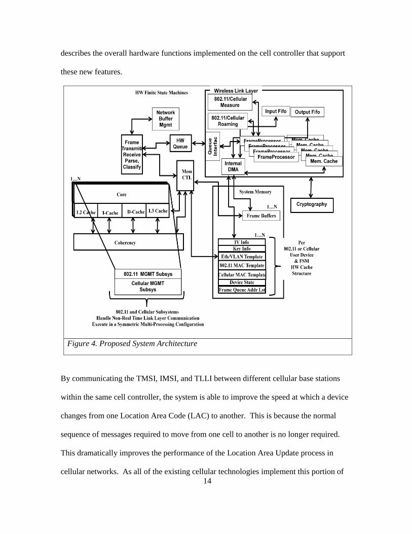
14
describes the overall hardware functions implemented on the cell controller that support
these new features.
Figure 4. Proposed System Architecture
By communicating the TMSI, IMSI, and TLLI between different cellular base stations
within the same cell controller, the system is able to improve the speed at which a device
changes from one Location Area Code (LAC) to another. This is because the normal
sequence of messages required to move from one cell to another is no longer required.
This dramatically improves the performance of the Location Area Update process in
cellular networks. As all of the existing cellular technologies implement this portion of

15
the specification as it is required when moving from one cellular coverage area to
another. Additionally, if the TMSI & TLLI are ensured to be unique across all cell
controllers, then this information can be moved in between interconnected cell controllers
thus improving performance further.
This new wireless system design is based upon the concept of splitting the wireless
Media Access Control (MAC) across interconnected cell controllers using specialized
hardware that process non-real time portions of the wireless MAC protocol as well as
handle high speed frame processing for wireless devices under its control. These cell
controllers make “intelligent” decisions based upon feedback from multiple radios within
a physical area. The wireless system design is comprised of hardware systems that are
connected utilizing unreliable communication media (Ethernet) but could utilize other
forms of unreliable communication such as satellite and wireless bridges as long as the
required communication delay does not violate time constraints imposed by the MAC
layer communication required between a central communication controller and radio that
communicates the wireless MAC protocol. Such a system needs to be capable of
providing ubiquitous RF coverage across many desperate physical locations as well as be
capable of integrating into existing, legacy network topologies that may be strictly based
upon wired communication technologies. The wireless system design utilizes RF
transmitters and receivers that perform real time data communication to devices. These
devices are typically mobile; however, they can also include stationary devices such as
desktop computers. The major components of the hardware system are comprised of the
following components:

16
Figure 5. Simplified System Topology
Figure 5 above depicts the overall system topology that looks deceptively simple. The
system topology describes the overall top level architecture. The hardware link layer
communication methods used in the overall system will now be described. The system
topology must be adaptable to ensure that the link layer design can be implemented
without violating existing cellular and WiFi standards. This introduces a challenge that is
addressed in the following manner.
Link Layer Communication Model
The link layer communication model splits both the cellular and the 802.11 MAC
protocols across unreliable communication links in a unique way. As depicted in Figure
5, Virtual Local Area Network (VLAN) technology as specified by the IEEE 802.1pq is
utilized between the cell controller and the base stations. In doing so, I can prioritize the
communication links dynamically. This design approach employs a fourfold advantage.
1. The new link layer communication model can be implemented across an existing
wired infrastructure with very low impact to the existing network infrastructure. As

17
an example, a network architect can overlay a completely different IP subnet over an
existing wired network infrastructure without changing the existing wired network.
2. Based upon link layer communication behavior, prioritization of wireless frames can
be changed dynamically. As an example, if Quality of Service (QoS) parameters
dictate a particular percentage of the system bandwidth, this system design can
quickly change the VLAN priority tag to prioritize frames to one RF base station over
another RF base station.
3. Unlike autonomous wireless routers and access points, the cell controller has
visibility to the RF spectrum where radios exist. This design enables the cell
controller to perform cognitive adaptation to the RF environment. Based upon the RF
noise temperature, the cell controller can equally distribute mobile devices across the
available RF spectrum in a fashion that provides for the greatest network
performance. As an example, BER as well as neighboring cell information
transmitted by the RF base station can be communicated back to the cell controller.
Neighbor cell information can be communicated in the form of Power Spectral
Density (PSD) calculations (this is covered in a later section). The cell controller can
make a dynamic decision to send data frames across a different RF base station, in
essence the device is now communicating with a different RF base station without
awareness by the mobile device. This is a form of a cognitive adaptation based upon
BER.
4. The integration of cellular and WiFi stacks provides the ability for cellular and WiFi
devices to utilize the same backhaul network infrastructure. This provides relief of

18
the cellular systems in regard to bandwidth utilization and improves the use of
unoccupied bandwidth on the backhaul network infrastructure.
The link layer design includes adapters for both WiFi and cellular technologies. 802.11
technology will be discussed first followed by cellular technology. As depicted in Figure
5, the wireless 802.11 MAC is split across unreliable communication links. RT messages
are addressed at the RF base station, while higher level management messages are
handled at the cell controller.
Figure 6. 802.11 Link Layer Subsystem Partition
The following 802.1l link layer subsystem functions are addressed in the RF base station.
The RF base station handles all RT messages. Since Probe Response messages are very
similar to Beacon Messages, Beacon Messages are also handled in the RF base station.

19
Table 1 802.11 Real-Time Messages
1 Beacon/DTIM
2 Probe Response
3 Acknowledgements
4 RTS/CTS (If Enabled)
Templates for these messages are sent by the cell controller to the RF base station for
purposes of transmission to their RF coverage area. When cells overlap, these messages
can also be forwarded by other RF base stations in the coverage area. A measure of the
received power (Eb/No) can be made and a decision in regard to which RF base station
should ultimately respond to later Association requests can be calculated. The following
diagram depicts an 802.11 example:
Figure 7. Probe Response Exemplar

20
On Ethernet there are two distinct delays: propagation delay and transmission delay. The
following equation describes the nodal delay, the delay per node in an Ethernet network.
(5)
The velocity of an electromagnetic wave through a copper media is approximately
. Though base transmission rate has no bearing on propagation
delay, base rate directly affects transmission rate . Assuming full duplex Ethernet
operation for a 64 byte frame. A probe request, including a
proprietary header, can be no less than this size; therefore, round trip (RT) delay of
2* . Assuming a maximum length of 100 meters,
with a round trip delay of 2* . Ignoring
for a moment, one RT segment is . Adding the segments
depicted in Figure 7 we have a . Figure 7 is representative of the
minimum network delay between a cell controller and a RF base station; therefore, the
802.11 messages depicted in Table 1 represent messages that must be handled in RT by
the RF base station.
Table 2 802.11 Non-Real Time Messages
1 Association/Reassociation/Disassociation
2 Authentication/Deauthentication
3 802.1x, EAPOL, etc…
4 802.11 Data Messages
WiFi messages listed in Table 2 are handled by the cell controller which manages
messages from all devices in a large regional area. These messages provide for a

21
centralized management of all 802.11 devices in the area as well as provide for the
accurate application of Quality of Service (QoS) between individual wireless networks
since all data frame are sent through the cell controller. For example, if a network
identifier (e.g. SSID) is suppose to have available 60% of the available bandwidth while
another network identifier is suppose to have available 40% of the available band, the
bandwidth between the two networks can be arbitrated in RT instantaneously since the
cell controller has full access to all traffic being delivered to the whole network prior to
be distributed to individual RF base stations in the regional areas.
Cellular Link Layer MAC
There are many system design differences between the different cellular technologies
(e.g. 2G/GSM, 3G/UMTS, 3G/CDMA2000, 4G/LTE). Cellular vendors have changed
their subsystem designs to improve access speeds, coverage, and reduce cost to
deployment. I will focus on cellular subsystems that intersect GSM, 3G/UMTS, and
4G/LTE cellular link layer subsystem functions. Unlike WiFi devices, cellular provider
networks have routinely (out of necessity) split their link layer communication across
unreliable communication links (e.g. Ethernet/Fiber).
Table 3 Example Cellular UMTS Messages (Wikipedia, 2014)
MOBILITY MANAGEMENT (MM)
MESSAGES
RADIO RESOURCE (RR)
MESSAGES
imsi detach/attach indication additional assignment
location updating reject immediate assignment
location updating request
immediate assignment extended
location updating response immediate assignment reject
authentication reject ciphering mode command
authentication request ciphering mode complete
authentication response assignment command
identity request assignment complete

22
identity response assignment failure
tmsi reallocation command handover command
tmsi reallocation complete handover complete
cm service accept handover failure
cm service reject physical information
cm service abort paging request type 1-3
cm service request system information type 1-8,2(bis/ter),
5(bis/ter)
cm establishment request channel mode modify {ack}
Abort classmark change/enquiry
mm status measurement report/
frequency redefinition
The cellular link layer communication model is much more distributed; however, there
are improvements that can be made. I will outline the link layer communication model
changes that integrate WiFi and cellular technologies together as well as improve
roaming between the technologies. In addition, I will describe why this approach is
superior to other approaches.
Figure 8. Example Inter-RAT Handover Setup (4G Source to 3G Target Network)
(Barton, 2012)

23
The example above describes the handover setup procedure example between a 4G
source to a 3G target network. The end goal is to ensure that when the handover is
complete data frames will be sent to the new serving gateway service in this the GGSN
3G service. The Source MME subsystem initiates the Handover resource allocation
procedure by sending a Forward Relocation Request (IMSI, Target Identification, CSG
ID, CSG Membership Indication, MM Context, PDN Connections, MME Tunnel
Endpoint Identifier for Control Plane, MME Address for Control plane, Source to Target
Transparent Container, RAN Cause, MS Info Change Reporting Action (if available),
CSG Information Reporting Action (if available), UE Time Zone, ISR Supported)
message to the target SGSN subsystem of the 3G cellular network. Note that this entire
setup process occurs before the User Equipment (UE) has actually “roamed” to the 3G
network. Once the setup has completed, the source MME subsystem initiates the
handover process by coordinating with the UE by sending a handover command
(depicted in Figure 9). The UE responds to the network with a handover complete
message to the target RNC subsystem who initiates a message to its SGSN subsystem
which then conveys a completion message to the source MME subsystem. The source
MME acknowledges the completion message and the SGSN notifies its GGSN service
(using a “Modify Bearer” request). Once the GGSN service then notifies the source
PGW of the change, data frames are now presented through the new serving 3G gateway
(e.g. SGSN and GGSN).
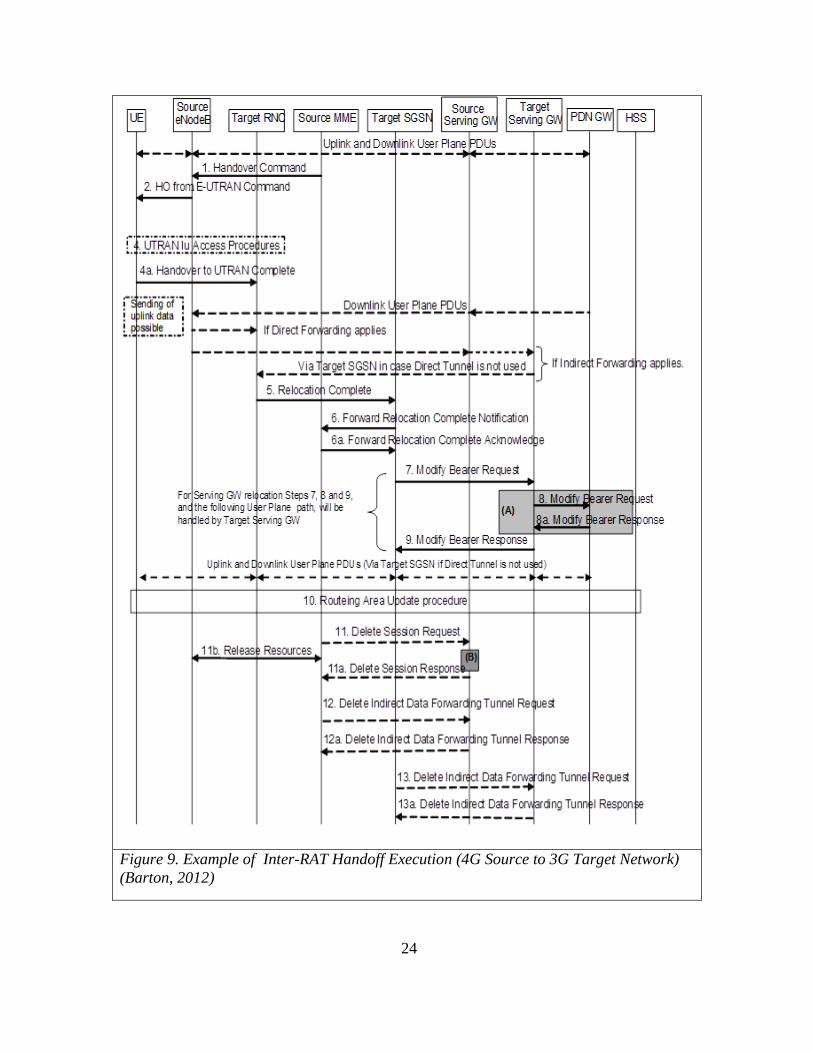
24
Figure 9. Example of Inter-RAT Handoff Execution (4G Source to 3G Target Network)
(Barton, 2012)
25
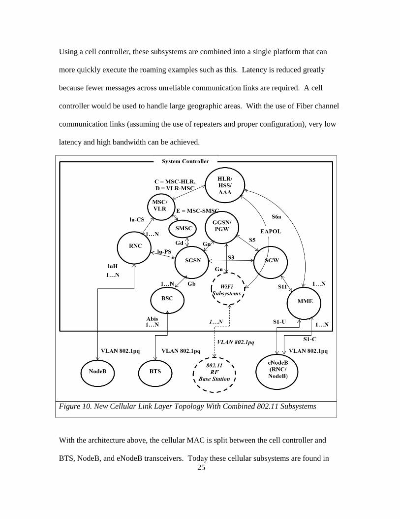
Using a cell controller, these subsystems are combined into a single platform that can
more quickly execute the roaming examples such as this. Latency is reduced greatly
because fewer messages across unreliable communication links are required. A cell
controller would be used to handle large geographic areas. With the use of Fiber channel
communication links (assuming the use of repeaters and proper configuration), very low
latency and high bandwidth can be achieved.
Figure 10. New Cellular Link Layer Topology With Combined 802.11 Subsystems
With the architecture above, the cellular MAC is split between the cell controller and
BTS, NodeB, and eNodeB transceivers. Today these cellular subsystems are found in

26
desperate locations across the country. Since these subsystems interact with each other
across vast physical locations, very little information is communicated in regard to the RF
environment as it relates to BER and RF performance. With this new link layer
architecture, cellular coverage can be provided for large geographic areas by the same
system controller. In this case a full hardware data path can be applied to handle frame
classification and distribution to the wireless subsystems required to handle this
processing as well as gather BER information in regard to RF performance in local areas.
This integrated with Wi-Fi capability provides the ability to off load traffic from the
cellular network, freeing up cellular bandwidth for other users. By the use of a 802.11
split MAC, we can now provide Authentication and Association credentials directly into
the cellular network using Extensible Authentication Protocol of Local Area Network
EAPOL. Using the same authentication triplets used between the service provider and
the UE, WiFi can be enabled and provide service to cellular UE. Just as is the case with
the Packet Gateway (PGW) or the Gateway GPRS Support Node (GGSN), Network
Address Translation (NAT) services are provided for IP addresses that are provided for
the local area. This service is used to go to the Internet from a UE that is using WiFi
instead of the straight cellular services. Because the WiFi base stations can be elevated,
and have amplification added for both transmit and receive, it is possible to use WiFi to
offload some cellular data traffic.
The link layer communication model has been described for both the 802.11 where the
RF MAC is split between a RF base station and the addition of the 802.11 subsystem to
cellular subsystems. The point areas where the 802.11 subsystems are integrated will

27
function correctly for all versions (e.g. GSM, UMTS, LTE) of cellular subsystems. In
addition, a method of authentication has been described as well as how access to the
Wide Area Network (WAN) is provided as is the case with all data services on UE.
Link Layer Hardware
In order to provide the best class of service for the link layer model described in the
previous section, the hardware must be designed to support the following features:
Table 4 Sample Link Layer Feature List
1 Link Layer Encryption/Decryption (Cellular & WiFi). Also encryption over the wired
network as well.
2 Frame Manager (Classification Engine), Queue Manager, and Data Path Acceleration
Architecture (DPAA)
3 Fixed format headers sent to wireless base stations
4 Table of all UE required
5 NAT and Proxy ARP provided for all bridged UE (different modes of operation), MAC
learning feature to support MAC address transition across Layer 2 switch interfaces.
6 High performance frame processing with little or no intervention with GPP HW
7 Large number of Fiber and Ethernet interfaces available in one unit
8 Security Fuses, secure boot, security monitor (can be connected to tamper detection).
9 Numerous other hardware attributes not relevant for a research paper such as dual power
supplies, solid state disks, etc...
The hardware design to support the link layer hardware would start with the design of the
SoC. This design would facilitate the use of dedicated hardware state machines that act
independently from each other. These hardware state machines are provided instructions
in memory that are then loaded into their internal register cache for execution. These
instructions facilitate the functions required to support the predefined headers found for
both the link layer Ethernet communication as well as the cellular and 802.11 MAC

28
fields. Since most of these fields are based upon configuration parameters that are
configured by software, it would the responsibility of the link layer software to
implement the structures that are accessed by the hardware to support this link layer
communication.
Figure 11. HW State Machines in SoC Architecture
The hardware state machines (as configured by software and depicted in Figure 11) used
for frame processing would contain internal register memory that is used to communicate
frames to a wireless base station. This internal register memory would be used to
construct the proper frame header for a particular device that has been configured. In
addition some hardware state machines would also include a hardware internal Direct
Memory Address (DMA) engine. When a base station device has properly authenticated

29
itself to the network, the base station MAC address, BSSID, radio MAC address(es),
VLAN header information, security key information, and capabilities will be
communicated and stored into system memory (not in hardware registers). When a
network frame buffer is received from a wireless base station, the hardware frame
classification engine would evaluate the source MAC address, VLAN tag information.
Based upon this information it will do further classification to identify the source MAC
address of the actual wireless client. The source MAC address would then translate to
unique hardware queue ID. A message with the address of the frame and that queue ID
would be sent to the hardware queue. This hardware queue is configured to send frames
with this queue ID to the security engine for link layer decryption. The security engine
returns a specific queue ID after decrypting this frame (based upon its hardware memory
cache structure). The hardware queue is configured to send frames with this queue ID to
the wireless link layer engine for further processing. As an example, based upon the
fields in the 802.11 MAC header, the wireless hardware engine will perform standard
operations on the frame starting at the address of the frame. The wireless link layer
hardware state machine is specifically designed to understand the 802.11 and UMTS
MAC protocols. Using 802.11 as an example, the hardware state machine behavior can
be based on the source (radio MAC) address of the sender in the forward direction. If the
destination MAC address is that of another wireless device that is managed by this cell
controller the frame will be forwarded onto the same queue that other frames from the
network in the reverse direction are placed for eventual transmission to the wireless
device.
30
Link layer encryption is based upon cryptographic algorithms verified and validated by
the The National Institute of Standards and Technology (NIST). NIST issued the Federal
Information Processing Standard (FIPS) Publication 140-2 (FIPS PUB 140-2) is a United
States government computer security standard that is used to accredit cryptographic
modules. This publication is titled “Security Requirements for Cryptographic Modules”
and was published on May 25, 2001 and was updated on December 3, 2002.
The National Institute of Standards and Technology (NIST) issued the FIPS 140
Publication Series to define requirements and standards for cryptography modules for
both hardware and software components developed by technology companies. Federal
agencies and departments can validate whether a module, termed a Hardware Security
Module, is covered by an existing FIPS 140-1 or FIPS 140-2 certificate which specifies
module name, hardware, software, firmware, and/or applet version numbers. Many
cryptographic modules are produced by the private sector (and even by the open source)
communities for use by the U.S. government and other regulated industries, including
financial and health-care institutions, that collect, store, transfer, share, and disseminate
sensitive but unclassified (SBU) information.
NIST regulated security programs enforce government and industry cooperation to
establish secure systems and networks by developing, managing and promoting security
assessment tools, techniques, and services, and supporting programs for testing,
evaluation and validation. NIST security programs extend to development and
maintenance of security metrics; security evaluation criteria and evaluation

31
methodologies; tests and test methods; security-specific criteria for laboratory
accreditation; guidance on the use of evaluated and tested products; research to address
assurance methods and system-wide security and assessment methodologies; security
protocol validation activities; and appropriate coordination with assessment-related
activities of voluntary industry standards bodies and other assessment regimes.
Annex C of FIPS 140-2 specifies Approved Random Number Generators. Random
Number Generators (RNG) are used to generate random content for cryptographic
algorithms that require the need of random content such as content required for the
generation of IV information for IPSEC or DTLS protocols as two examples.
United States Federal Government standard Federal Information Processing Standard
(FIPS) Publication 140-2 (FIPS PUB 140-2) requires verification that each sample
produced by a Random Number Generator (RNG) be compared against the immediately
preceding sample to verify that the random number generator does not generate the same
numeric value twice sequentially; statistically, this would indicate a hardware or software
fault rather than a coincidence. FIPS 140-2 specifies that any time a Random Number
Generator (RNG) generates a new random number, the generated number is to be
compared against a previously generated random number. If the two are the same, the
event indicates a hardware (or software) failure rather than by some extraordinary,
statistical chance. If the two are the same, an error indication is generated.
32
In order for any system to be compliant with requirements such as FIPS 140-2, but not
perform the check in software, the hardware must enable the security engine utilizing a
“bump in the wire” architecture in a mostly-hardware autonomous data path to perform
this function. Thus, security can be implemented in separate devices interposed between
devices intended to communicate securely, for example cellular link layer encryption
datagram, 802.11 link layer datagram and insecure Internet Protocol (IP) datagrams can
be repackaged securely for transport over the public Internet or other unprotected
network infrastructure.
The design of a RNG requires the use of hardware design techniques known as
“Asynchronous Design”. When using asynchronous design techniques to design a RNG
subsystem, one must use the instability inherent in relying upon propagation delays in a
logic design that vary with temperature, voltage level fluctuation, substrate differences,
and register settling time that occur through combinatorial logic designs. These
techniques are used to ensure that the RNG subsystem does provide random numbers
with sufficient entropy. The following illustrative technique can facilitate random
number generator verification, which may be performed without using any
microprocessor execution time or specialized hardware.

33
Figure 12. Use of Random Numbers in HW Data Path
An input frame that requires encryption is received by the hardware data path and is
parsed, stored in system memory (1 in Figure 12) by the hardware receive DMA engine.
A message is sent by the frame parser to the HW queue across a hardware bus. This
message contains the address of the HW cache associated to the queue ID in system
memory (2b in Figure 12). The Queue Interface reads the message in the HW Queue (2a
in Figure 12) and alerts the DMA to read the HW memory using the address found in the
HW Queue message) and distribute a processing request to a CryptoEngine (3 in Figure
12). The Queue Interface also instructs the DMA to read the Frame Buffer memory using

34
the address found in the HW Queue message (4 in Figure 12). The CryptoEngine
requests a random number because it must generate an IV. This IV contains a mask (e.g.
seed) that is XOR’d with the random number (5 in Figure 12). Finally, the CryptoEngine
executes its loaded instructions (in its internal memory cache) and checks the newly
generated IV to the previous IV. If these IV’s are identical, it is indicative of a problem
and an error is returned, otherwise the new IV is stored at the address of the previous IV
by use of its DMA engine and processing continues normally (6 in Figure 12).
This process illustrates a FIPS compliant hardware design to meet the cryptographic
needs of the cell controller.
Link Layer Software
The link layer software is comprised of the following subsystems that interact with the
hardware state machines described in the hardware section above. The software must
pre-populate the hardware memory of the state machines to accommodate the
transmission of frames to wireless device from other wireless devices as well as devices
from the WAN side of the network device. Network headers that are used to
communicate to the wireless base stations must be pre-populated on a per-flow basis.
The following depicts the headers that must be pre-populated. Note that the wireless link
layer engine will modify some portions of the header as data moves through the
autonomous hardware data path.
35
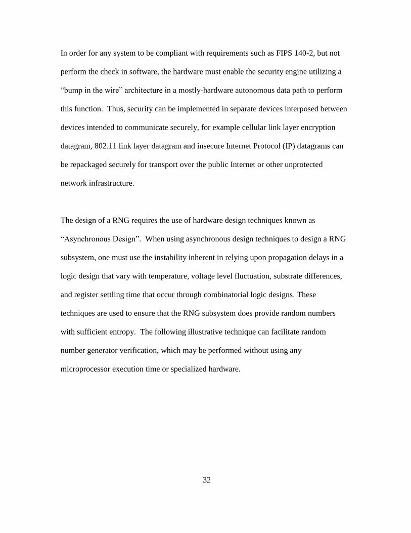
Figure 13. Network Frame Headers that most be pre-populated on a per
Flow basis
As described in Figure 11, the wireless link layer engine requires HW memory cache that
contains the proper Ethernet, VLAN, Cellular or 802.11 MAC header pre-populated on a
per flow basis. This means two per wireless device (1 for the forward direction and 1 for
the reverse direction) flow to and from a wireless device. Figure 13 describes the
network header formats that must be pre-populated in the wireless link layer hardware
state machine. This finite state machine (FSM) must also maintain flow control
structures between the cell controller and the RF base stations. There are mechanisms in
place in regard to the cellular protocol specification; however, on the 802.11 side there
are not integrated specifications. The following frame formats are specified to support
link layer communication between the RF base stations and the cell controller:

36
Figure 14. Frame Format Examples

37
CHAPTER 3
MOBILE AND BASE STATIONS
Wireless State Machines
Cellular and 802.11 devices are constantly measuring the RF environment. As such they
are constantly performing neighbor cell power measurements, if sufficient BER rate is
sensed by the receiver (where rate adaptation did not improve), a 802.11 client device
will initiate its form of cell reselection (issues a 802.11 Reassociation request). On
cellular devices this is performed by monitoring all BCCH carriers contained and making
one measurement per BCCH carrier. The size of the neighbor cell list (e.g. number of
neighboring transmitters), either increases or decreases the amount of time UE spend
performing these measurements. Cellular devices initiate the process of cell reselection
by a process referred to as Location Area Update (LAU). This process is analogous to
the example when in a moving vehicle. The cellular device in your hand will receive a
signal from a new tower which will have a different Location Area Code (LAC). This
process is repeated as the car continues to move from one tower to the next. This process
is sufficient for voice services, while processes referred to as Routing Area Update and
MM Attach is required for data services. A cellular device can also request
supplementary services such as [no] call waiting, [no] call forwarding, and activate Short
Message Service (SMS).

38
Finite State Machine Behavior
Figure 15 depicts the cell reselection state machine. The and the
field values are transmitted on the Broadcast Channel (BCCH) of a
cellular base station. In order to distribute the load of cellular devices across cellular base
stations, the cell controller can dynamically modify the parameters being transmitted on
this channel thereby influencing the state machine of the UE to connect to a different RF
base station. For UMTS and LTE UE, the network can also request a cell reselection.
Use CS Cell
Reselection parameters
C1 & C2 (-Or if MS
class ‘A’ in dedicated
mode, report
measurements and
handovers N/W
controlled)
Utilize GPRS Cell
Reselection Parameters
C1, C31, C32
Yes
Yes
No
No
Does the cell offer GPRS services? (Indicated by SI3, SI4, & SI13)
Does the cell offering GPRS services have a PBCCH?
Is the MS GPRS MM attached?
Yes No
Is this a class A MS in CS dedicated mode?
No Yes
Figure 15. Cellular Cell Reselection Rule Evaluation Process
(6)
= Average receive signal level

39
= Minimum the MS must receive to access this cell
Maximum power the MS is allowed to transmit on the
RACH
= MS power class
(7)
= dB weighting applied to a cell which may be positive or
negative
= Positive dB weighting applied to a cell for the time
= Timer set in the MS by the neighbor cell; on it expiry, the
is removed. is only applied to neighbor cells.
In addition, cellular and 802.11 wireless devices also perform rate adaptation based upon
sensed BER information. An 802.11 wireless client device normally initiates a
Reassociation request, while a cellular device utilizes the LAU procedure as well as
manage the cell reselection.
40
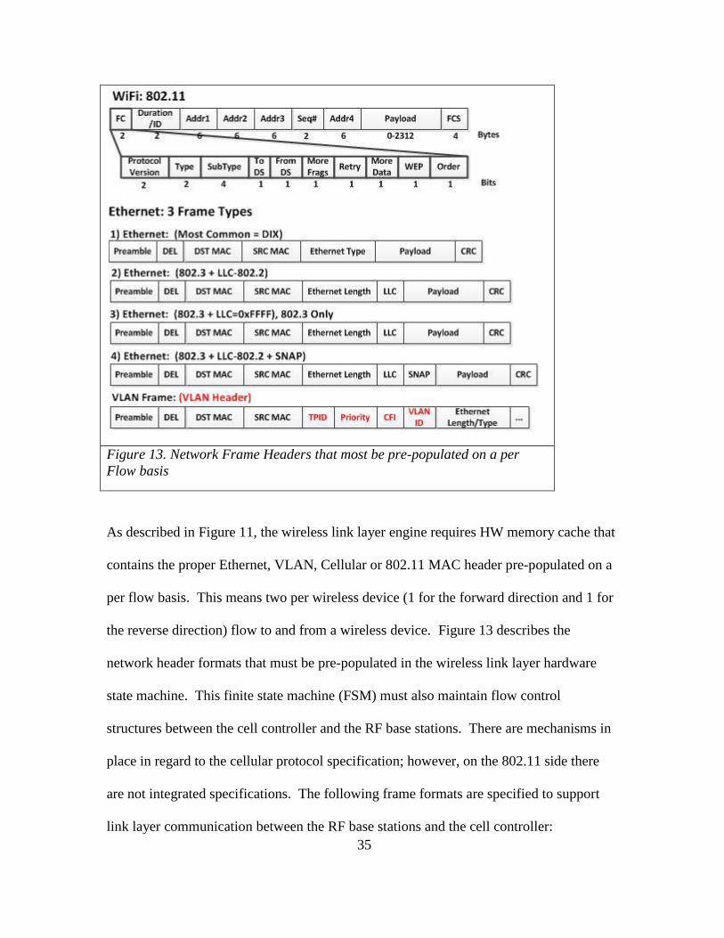
Figure 16 LTE Handset (Basic State Machine Terminology)(ShareTechnote, 2013)
An example LTE cell reselection, initiated by the network side: A UE is in connection
with a cell ‘A’. The network sends a command to the UE to perform a signal quality
measurement on cell ‘B’ (e.g. UMTS command = “Measurement Control”, while LTE
command = “RRC Connection Reconfiguration”). The UE performs the measurement
and sends the result to Cell ‘A’. (e.g. UMTS and LTE = “Measurement Report”). If the
controller deems the measurement favorably, the UE is sent a change cell command. (e.g.
UMTS command = “Physical Channel Reconfiguration or ActiveSetUpdate”, while LTE
= “RRC Connection Reconfiguration”). Once the UE changes to cell ‘B’ successfully,
the UE will send a cell change completion message to cell ‘B’ (e.g. UMTS = “Physical

41
Channel Reconfiguration Complete or ActiveSetUpdateComplete”, while LTE = “RRC
Connection Reconfiguration Complete”). (ShareTechnote, 2013)
LTE phones presently have two antennas that can be used in a 2x2 MIMO mode. The
LTE phone can use one antenna to talk to one tower while using the second antenna to
communicate to the second cell tower.
Roaming
In 802.11 roaming to another access point involves sending a ‘Reassociation” request to
the new access point. This “new” access point was discovered by an outcome of signal
strength measurements by the client device. In the 802.11 state machine below, the
Reassociation message speeds up the Authentication and Association state change so it
more quickly moves to the successfully Authenticated and Associated state. When a
wireless device roams, it is important that data transfer is not lost during the process. The
MS state machine has an impact on this behavior. When a 802.11 device sends it
“ReAssociation” message, it must still properly receive frames from the base station it is
presently Associated to. In addition, if the base station it is roaming to does not have
direct communication and coordination with the base station it is roaming from the
device will be forced to perform a complete Association to the device it is roaming to.
With the cell controller link layer approach, the roaming between access points can be
seamless. The following state machine diagram depicts the change in the typical state
machine behavior of the mobile device.

42
Figure 17. Example of 802.11 Roaming Utilizing Cell Controller Concept
The remote sensing software that manages the hardware link layer (e.g. 802.11/Cellular
Measure) RF measurement subsystem either measures that the RF energy from a
particular device is actually stronger on a different RF base station that it is presently
receiving data or that a Reassociation message is received from that device. In either
case, a seamless roaming event is initiated by the software (refer to 1 in Figure 17). This
software modifies the per device table managed in memory using the Queue Interface
specified above. The Queue Interface is the only hardware entity that can assure the
change to this shared memory location is updated atomically without interrupt to other
43
processing flows and to the hardware that is processing the hardware data path. The
fields updated are the pre-populated Eth/VLAN header template, the 802.11 MAC to
reflect a change to any 802.11 parameters required such as BSSID & RF MAC address
change, and device state (refer to 2 in Figure 17). Note that the Frame Queue Address
List (records addresses of all frames to be transmitted to a device), Key and IV
information is not modified; therefore, frames queued toward the wireless device will be
sent to the new RF base station immediately when the change occurs through 802.1pq
link layer communication toward the correct RF base station.
Cellular Roaming
The cell controller commands mobile devices thru their mobile station (MS) to perform a
measurement of a neighboring cell. The cellular measurement subsystem is used to
continually command a measurement of neighboring RF base stations. Software
executing on one or more cores makes a decision based upon signal strength as well as
traffic load across the base stations. The cell controller makes it possible to better
understand the RF environment in regional areas and to be more responsive to changes in
these areas.
44
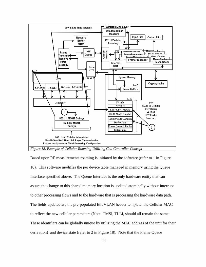
Figure 18. Example of Cellular Roaming Utilizing Cell Controller Concept
Based upon RF measurements roaming is initiated by the software (refer to 1 in Figure
18). This software modifies the per device table managed in memory using the Queue
Interface specified above. The Queue Interface is the only hardware entity that can
assure the change to this shared memory location is updated atomically without interrupt
to other processing flows and to the hardware that is processing the hardware data path.
The fields updated are the pre-populated Eth/VLAN header template, the Cellular MAC
to reflect the new cellular parameters (Note: TMSI, TLLI, should all remain the same.
These identifiers can be globally unique by utilizing the MAC address of the unit for their
derivation) and device state (refer to 2 in Figure 18). Note that the Frame Queue
45
Address List (records addresses of all frames to be transmitted to a device), Key
(authentication triplet) and IV information is not modified; therefore, frames queued
toward the wireless device will be sent to the new cellular RF base station immediately
when the change occurs through 802.1pq link layer communication toward the correct
cellular RF base station.
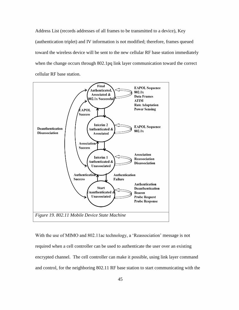
Figure 19. 802.11 Mobile Device State Machine
With the use of MIMO and 802.11ac technology, a ‘Reassociation’ message is not
required when a cell controller can be used to authenticate the user over an existing
encrypted channel. The cell controller can make it possible, using link layer command
and control, for the neighboring 802.11 RF base station to start communicating with the

46
wireless client (using its second antenna) in a 2x2 MIMO configuration while the
wireless client device is still communicating with the other RF base station through the
use of the other antenna. The RF base stations would need to be told to not answer on its
second antenna for this client device. This is acceptable since the RF base station must
transmit ACKs with the BSSID of the network it is associated to. The client device
would not know that the second spatially diverse antenna it was using is on another RF
base station. The cell controller would make the decision as to when to complete the full
process of 802.11 roaming. This process is identical to the method used by LTE mobile
devices. LTE devices can utilize their second antenna in a 2x2 MIMO configuration to
interact with multiple base stations simultaneously. This requires only software support
for the proper analysis of eigenvectors to be performed on the 802.11 client based upon
the concept of having two (very separated) spatially diverse streams possibly on two
separate channel frequencies.
Power Spectral Density Estimation
In order for mobile devices to make roaming decisions, these devices must calculate
power spectral density. In addition, channel information from a RF base station can be
provided to the cell controller to determine and estimate the active signals in the area. An
evaluation of PSD and estimation techniques will now be described. To calculate the
power of a W-CDMA signal, we must integrate over the entire bandwidth of the signal.
For instance, a WCDMA signal based upon the 3GPP WCDMA Frequency Division
Duplex (FDD) release 99 Downlink Dedicated Physical Channel (DPCH) with a
bandwidth of 5MHz will generate the following Power Spectral Density plot.

47
Figure 20. Example Spread Spectrum Tx (5 MHz)

48
Figure 21. Example Spread Spectrum Rx (5 MHz) Mixed with AWGN
Other signals of interest can be derived from base stations in the area. These base
stations can perform signal analysis of the RF environment and report the results of this
analysis to the cell controller. Such information can be used to determine why high
incidents of BER are reported in specific cell coverage areas. I studied signal estimation
and detection methods with the goal to determine the best Power Spectral Density (PSD)
estimation method for the derivation of the PSD of sinusoid signals in the presence of
white noise utilizing different estimation methods. In order to achieve this goal, I will
utilize two general classification methods: non-parametric and parametric methods. Non-
parametric methods derive their PSD estimate directly from the input data. Parametric

49
methods model the data as an output of a linear system driven by White Gaussian Noise
(e.g. W.G.N) with a specified variance so system parameters can be estimated. I will
utilize two different input levels: Level 1: Three input sinusoids, Level 2: Three input
sinusoids and regenerated random noise (for each factor).
I will utilize the following estimation methods as my factors in this experiment:
Blackman-Tukey correlogram, Welch Periodogram, Yule-Walker, Burg, Covariance,
Modified Covariance, and Multiple Signal Classification (MUSIC). I then utilize the
analysis of variance (ANOVA) method to analyze the variance within each estimation
method as well as the variances between different estimation methods.
Factors and Factor Ranges
For each estimation method, I will vary the ranges of the factor to best illustrate
frequency resolution and derivation of power spectral density. Though I will utilize a
Hamming Window for both the correlogram and periodogram estimation methods, the
ranges of the factors will be different for both the correlogram and periodogram
estimation methods. I will use the following lag ranges for the correlogram estimation
method as 10, 20, and 70. In the equation below L indicates the lag index and is
computed using the Discrete Time Fourier Transform (DTFT) of the autocorrelation
sequence.
(8)

50
For the periodogram estimation method, I will use different shift adjustments for the
analysis window. By utilizing an analysis window, I can cause different overlapping
sequences and therefore improve the PSD estimate. In the equation below, n represents
the index of the input sample sequence.
(9)
Again, the input sequence can be overlapped (accomplished by utilizing different shift
adjustments) to improve the power spectral density estimate. I will use the following
shift adjustments for the periodogram estimation method as 10, 20, and 30.
For the Yule-Walker, Burg, Covariance (& modified covariance), and MUSIC PSD
estimation methods, I will utilize model order 5, 15, and 30. The following is the
equation used to calculate the Yule-Walker PSD:
(10)
Since the Burg method is an AR process, the following is the equation used to calculate
the Burg PSD:
(11)
The value is derived by utilizing a harmonic mean between the forward and
backward partial correlation coefficients to calculate the reflection coefficient, . Once

51
these AR parameters are calculated, the PSD estimate is calculated as described in the
equation above.
(12)
At each order, P, the variance of the forward and backward linear error prediction is
minimized. This calculated utilizing an arithmetic mean:
(13)
Since the Covariance method is also an AR process, the following is the equation used to
calculate the Covariance PSD:
(14)
The following is how to compute the covariance matrix of a signal x of time series length
N, with maximum lag M:
(15)
and individual elements of Rp:
(16)
This PSD algorithm minimizes the forward error prediction utilizing least squares to
determine AR parameters, .

52
Since the Modified Covariance method is also an AR process, the following is the
equation used to calculate the Modified Covariance PSD:
(17)
The following is how to compute the covariance matrix of a signal x of time series length
N, with maximum lag M:
(18)
and individual elements of Rp:
(19)
This PSD algorithm minimizes the both the forward error prediction and the backward
error prediction utilizing least squares to determine AR parameters, .
The ‘pseudo’ (not true PSD) MUSIC spectrum estimate is derived from the following
equation:
(20)
The power spectral density information is lost when utilizing the MUSIC algorithm;
however, it is quite useful in the derivation of the frequency components of signals
embedded in white noise.
Levels
I will input the following signal combinations (Levels):
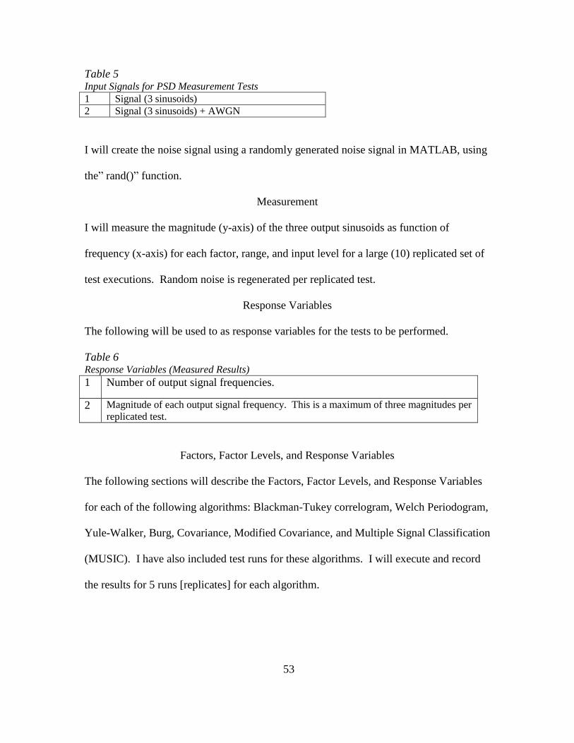
53
Table 5 Input Signals for PSD Measurement Tests
1 Signal (3 sinusoids)
2 Signal (3 sinusoids) + AWGN
I will create the noise signal using a randomly generated noise signal in MATLAB, using
the” rand()” function.
Measurement
I will measure the magnitude (y-axis) of the three output sinusoids as function of
frequency (x-axis) for each factor, range, and input level for a large (10) replicated set of
test executions. Random noise is regenerated per replicated test.
Response Variables
The following will be used to as response variables for the tests to be performed.
Table 6 Response Variables (Measured Results)
1 Number of output signal frequencies.
2 Magnitude of each output signal frequency. This is a maximum of three magnitudes per
replicated test.
Factors, Factor Levels, and Response Variables
The following sections will describe the Factors, Factor Levels, and Response Variables
for each of the following algorithms: Blackman-Tukey correlogram, Welch Periodogram,
Yule-Walker, Burg, Covariance, Modified Covariance, and Multiple Signal Classification
(MUSIC). I have also included test runs for these algorithms. I will execute and record
the results for 5 runs [replicates] for each algorithm.

54
Blackman-Tukey Test Factors, Factor Levels, and Response Variables
Three input sinusoids at the following frequencies: 10Hz, 11Hz, and 25Hz, with Factor
having 3 levels: 10, 20, and 70. Factor: Lag equals variable ‘L’ as used in the following
equation:
(21)
Figure 22. Blackman-Tukey (Signal +no noise, left plot: Signal+noise, right plot),
Hamming Window, Lag = 70

55
Figure 23. Blackman-Tukey (Signal+no noise, left plot: Signal+noise,
right plot), Hamming Window, Lag = 20

56
Figure 24. Blackman-Tukey (Signal+no noise, left plot: Signal+noise, right plot),
Hamming Window, Lag = 10
Welch Test Factors, Factor Levels, and Response Variables
Three input sinusoids at the following frequencies: 10Hz, 11Hz, and 25Hz, with Factor
having 2 levels: Shift Index 10 and 20. Factor: Shift index used in the following
equation. The shift index is used to overlap the input sequence in the equation
below.
(22)

57
Figure 25. Welch Periodogram (Signal +No Noise, left plot, Signal+Noise, right
plot), Hamming Window, Shift = 20

58
Figure 26. Welch Periodogram (Signal +No Noise, left plot, Signal+Noise, right
plot), Hamming Window, Shift = 10
Yule-Walker Test Factors, Factor Levels, and Response Variables
Three input sinusoids at the following frequencies: 10Hz, 11Hz, and 25Hz, with Factor
having 3 levels: Model Order 5, 15, and 30. Factor: Model order is used in the following
equation. The model order represents the ‘p’ summation range in the equation below.
The following is the equation used to calculate the Yule-Walker PSD:
(23)

59
Figure 27. Yule-Walker, (Signal+No Noise, left plot, Signal+Noise, right plot) Biased
ACF, Model Order = 30

60
Figure 28. Yule-Walker, (Signal+No Noise, left plot, Signal+Noise, right plot) Biased
ACF, Model Order = 15

61
Figure 29. Yule-Walker, (Signal+No Noise, left plot, Signal+Noise, right plot) Biased
ACF, Model Order = 5
Burg Test Factors, Factor Levels, and Response Variables
Three input sinusoids at the following frequencies: 10Hz, 11Hz, and 25Hz, with Factor
having 3 levels: Model Order 5, 15, and 30. Factor: Model order is used in the following
equation. The model order represents the ‘p’ summation range in the equation below.
(24)
Unlike the Yule-Walker AR process, the value for the Burg PSD estimator, is
derived by utilizing a harmonic mean between the forward and backward partial
correlation coefficients to calculate the reflection coefficient, . Once these AR

62
parameters are calculated, the PSD estimate is calculated as described in the equation
above.
(25)
At each order, P, the variance of the forward and backward linear error prediction is
minimized. This calculated utilizing an arithmetic mean:
(26)
Figure 30. Burg PSD, (Signal+No Noise, left plot, Signal+Noise, right
plot), Model Order = 30

63
Figure 31. Burg PSD, (Signal+No Noise, left plot, Signal+Noise, right
plot), Model Order = 15
Figure 32. Burg PSD, (Signal+No Noise, left plot, Signal+Noise, right
plot), Model Order = 5
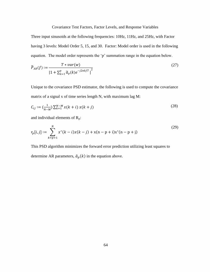
64
Covariance Test Factors, Factor Levels, and Response Variables
Three input sinusoids at the following frequencies: 10Hz, 11Hz, and 25Hz, with Factor
having 3 levels: Model Order 5, 15, and 30. Factor: Model order is used in the following
equation. The model order represents the ‘p’ summation range in the equation below.
(27)
Unique to the covariance PSD estimator, the following is used to compute the covariance
matrix of a signal x of time series length N, with maximum lag M:
(28)
and individual elements of Rp:
(29)
This PSD algorithm minimizes the forward error prediction utilizing least squares to
determine AR parameters, in the equation above.
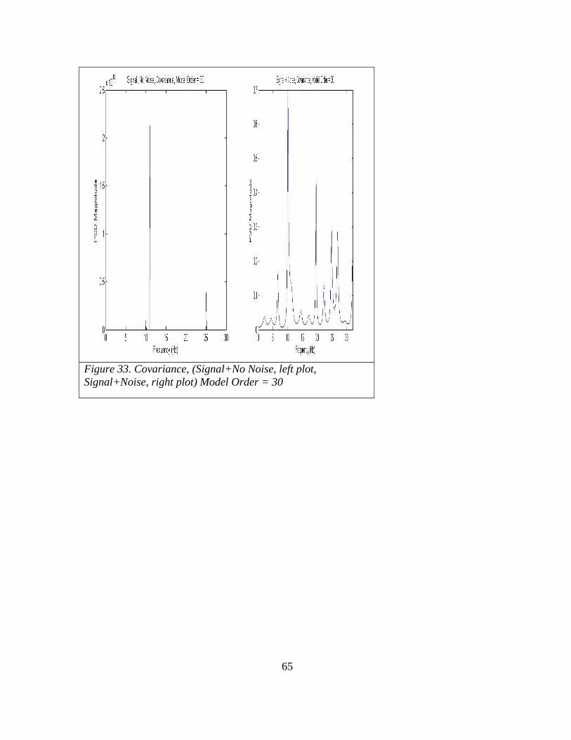
65
Figure 33. Covariance, (Signal+No Noise, left plot,
Signal+Noise, right plot) Model Order = 30

66
Figure 34. Covariance, (Signal+No Noise, left plot, Signal+Noise,
right plot) Model Order = 15

67
Figure 35. Covariance, (Signal+No Noise, left plot, Signal+Noise, right
plot) Model Order = 5
Modified Covariance Test Factors, Factor Levels, and Response Variables
Three input sinusoids at the following frequencies: 10Hz, 11Hz, and 25Hz, with Factor
having 3 levels: Model Order 5, 15, and 30. Factor: Model order is used in the following
equation. The model order represents the ‘p’ summation range in the equation below.
(30)
The following is how to compute the covariance matrix of a signal x of time series length
N, with maximum lag M:
(31)
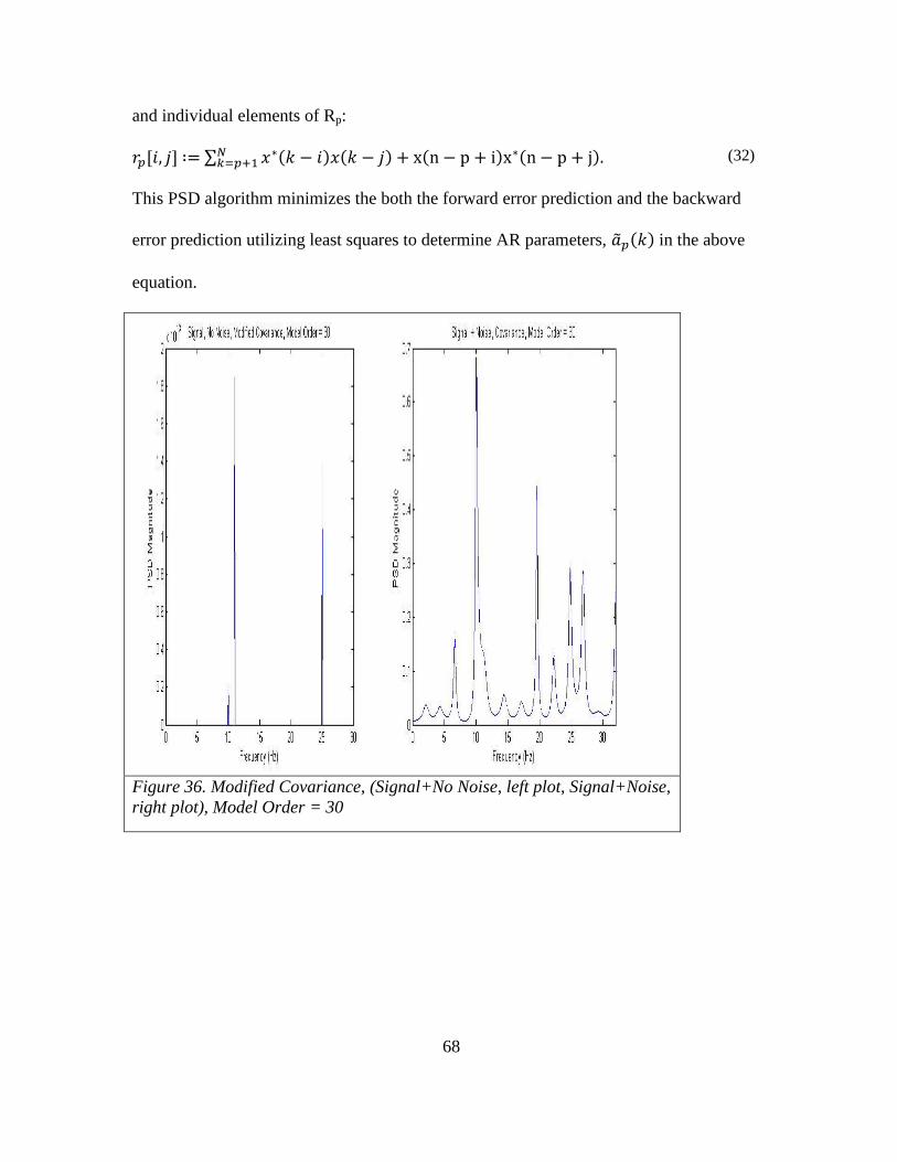
68
and individual elements of Rp:
(32)
This PSD algorithm minimizes the both the forward error prediction and the backward
error prediction utilizing least squares to determine AR parameters, in the above
equation.
Figure 36. Modified Covariance, (Signal+No Noise, left plot, Signal+Noise,
right plot), Model Order = 30

69
Figure 37. Modified Covariance, (Signal+No Noise, left plot, Signal+Noise,
right plot), Model Order = 15
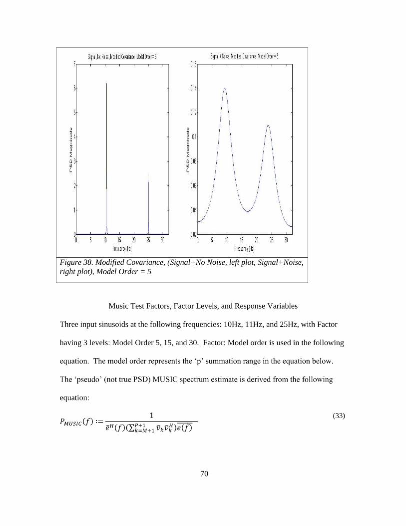
70
Figure 38. Modified Covariance, (Signal+No Noise, left plot, Signal+Noise,
right plot), Model Order = 5
Music Test Factors, Factor Levels, and Response Variables
Three input sinusoids at the following frequencies: 10Hz, 11Hz, and 25Hz, with Factor
having 3 levels: Model Order 5, 15, and 30. Factor: Model order is used in the following
equation. The model order represents the ‘p’ summation range in the equation below.
The ‘pseudo’ (not true PSD) MUSIC spectrum estimate is derived from the following
equation:
(33)

71
Figure 39. MUSIC PSD, (Signal+No Noise, left plot, Signal+Noise, right plot)
Model Order = 30

72
Figure 40. MUSIC PSD, (Signal+No Noise, left plot, Signal+Noise, right plot),
Model Order = 15

73
Figure 41. MUSIC PSD, (Signal+No Noise, left plot, Signal+Noise, right plot),
Model Order = 5
74
JMP Results
I model three input signals described above using MATLAB. Each signal was mixed
with White Gaussian Noise (WGN) with zero mean. I utilized the following estimation
methods as my algorithms in this experiment: Blackman-Tukey correlogram, Welch
Periodogram, Yule-Walker, Burg, Covariance, Modified Covariance, and Multiple Signal
Classification (MUSIC). I then measured the accuracy of the estimation method using a
low, medium, and high resolution factor (pertinent to each algorithm). The goal of this
test is determine which estimation algorithm is most accurate given similar resolution
factors. The way this is measured is to determine if, when I input three signals mixed
with random noise (two signals very close in frequency), that I can accurately estimate
the frequency of all three signals on the output. I ran 10 runs with each algorithm using a
random estimation model with a low, medium, and resolution factor for each algorithm.
JMP Output Data
The following output data was produced by JMP. I performed several tests to determine
if there was any interaction between the main effects: Algorithm and Resolution, as well
as, test the variances of each algorithm. I executed a one-way ANOVA, a two-way
ANOVA, several means tests, and finally the conclusion drawn from the two-way
ANOVA test output.
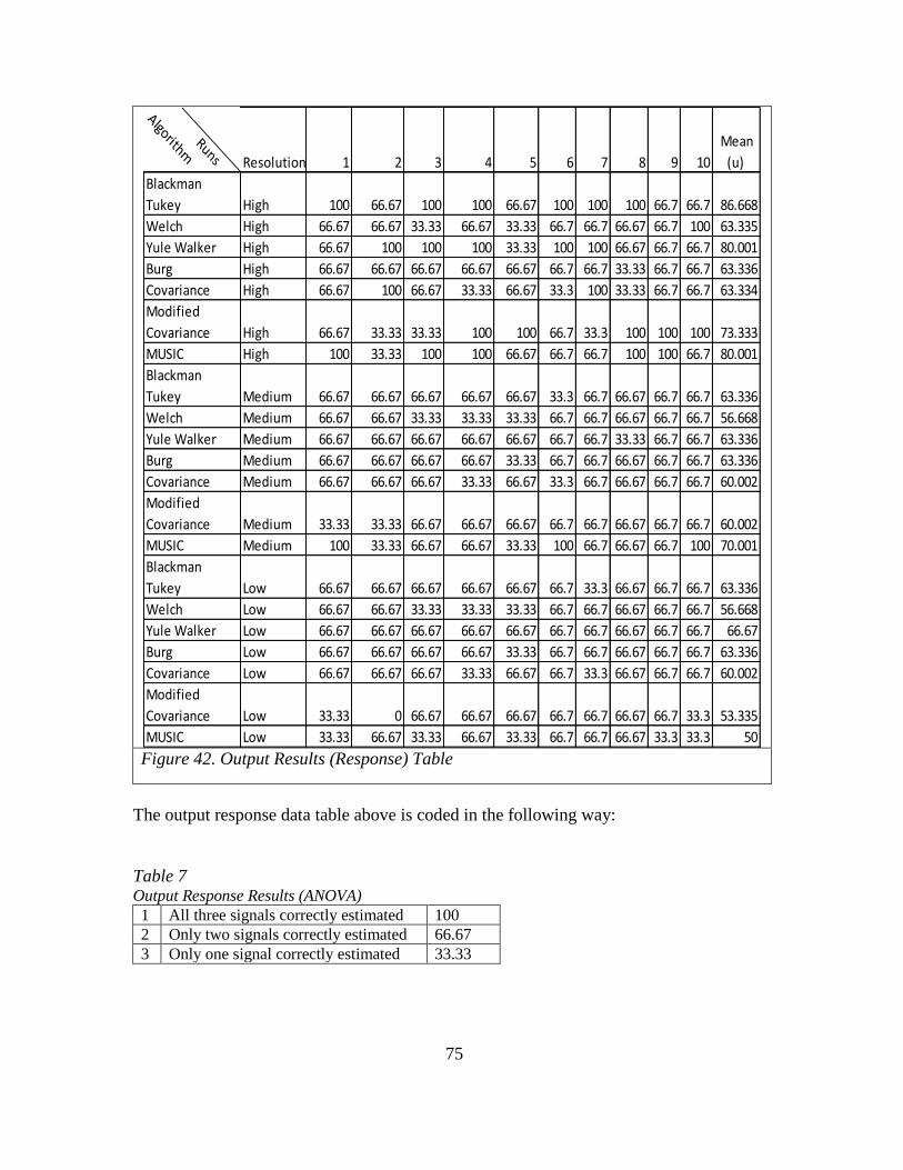
75
Figure 42. Output Results (Response) Table
The output response data table above is coded in the following way:
Table 7 Output Response Results (ANOVA)
1 All three signals correctly estimated 100
2 Only two signals correctly estimated 66.67
3 Only one signal correctly estimated 33.33
Runs
AlgorithmResolution 1 2 3 4 5 6 7 8 9 10
Mean
(u)
Blackman
Tukey High 100 66.67 100 100 66.67 100 100 100 66.7 66.7 86.668
Welch High 66.67 66.67 33.33 66.67 33.33 66.7 66.7 66.67 66.7 100 63.335
Yule Walker High 66.67 100 100 100 33.33 100 100 66.67 66.7 66.7 80.001
Burg High 66.67 66.67 66.67 66.67 66.67 66.7 66.7 33.33 66.7 66.7 63.336
Covariance High 66.67 100 66.67 33.33 66.67 33.3 100 33.33 66.7 66.7 63.334
Modified
Covariance High 66.67 33.33 33.33 100 100 66.7 33.3 100 100 100 73.333
MUSIC High 100 33.33 100 100 66.67 66.7 66.7 100 100 66.7 80.001
Blackman
Tukey Medium 66.67 66.67 66.67 66.67 66.67 33.3 66.7 66.67 66.7 66.7 63.336
Welch Medium 66.67 66.67 33.33 33.33 33.33 66.7 66.7 66.67 66.7 66.7 56.668
Yule Walker Medium 66.67 66.67 66.67 66.67 66.67 66.7 66.7 33.33 66.7 66.7 63.336
Burg Medium 66.67 66.67 66.67 66.67 33.33 66.7 66.7 66.67 66.7 66.7 63.336
Covariance Medium 66.67 66.67 66.67 33.33 66.67 33.3 66.7 66.67 66.7 66.7 60.002
Modified
Covariance Medium 33.33 33.33 66.67 66.67 66.67 66.7 66.7 66.67 66.7 66.7 60.002
MUSIC Medium 100 33.33 66.67 66.67 33.33 100 66.7 66.67 66.7 100 70.001
Blackman
Tukey Low 66.67 66.67 66.67 66.67 66.67 66.7 33.3 66.67 66.7 66.7 63.336
Welch Low 66.67 66.67 33.33 33.33 33.33 66.7 66.7 66.67 66.7 66.7 56.668
Yule Walker Low 66.67 66.67 66.67 66.67 66.67 66.7 66.7 66.67 66.7 66.7 66.67
Burg Low 66.67 66.67 66.67 66.67 33.33 66.7 66.7 66.67 66.7 66.7 63.336
Covariance Low 66.67 66.67 66.67 33.33 66.67 66.7 33.3 66.67 66.7 66.7 60.002
Modified
Covariance Low 33.33 0 66.67 66.67 66.67 66.7 66.7 66.67 66.7 33.3 53.335
MUSIC Low 33.33 66.67 33.33 66.67 33.33 66.7 66.7 66.67 33.3 33.3 50

76
Each algorithm is listed with its resolution factor level of Low, Medium, or High. We
expect to see the best results for each algorithm using the high resolution factor level.
JMP ANOVA (One-Way)
Figure 43. ANOVA analysis of output results (Plot 1: (L) Algorithm vs Mean & Plot 2: (R)
Resolution vs Mean)

77
Response variable = mean output. I compared the mean output to both the algorithm and
the resolution of the algorithm model. I should see parallel quantile plots data versus
normal distribution. The tilt of each plot line indicates different standard deviations.
Also, the distance between the plot lines indicates differences in variances. I do note the
variances are different for each algorithm. Additionally, it is clear that the Burg
algorithm has the smallest variance. The different quantile box sizes strongly indicate
different variances.
Figure 44. ANOVA analysis of output results ((L) Algorithm vs Mean & (R) Resolution vs
Mean)
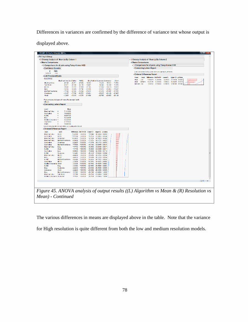
78
Differences in variances are confirmed by the difference of variance test whose output is
displayed above.
Figure 45. ANOVA analysis of output results ((L) Algorithm vs Mean & (R) Resolution vs
Mean) - Continued
The various differences in means are displayed above in the table. Note that the variance
for High resolution is quite different from both the low and medium resolution models.

79
JMP ANOVA (Two-Way)
Figure 46. (2-Way ANOVA) Full Factorial
The purpose of this test is to determine any interactions of the main effects. The Main
effects: Algorithm and Resolution with their interaction (Algorithm and Resolution). The
Least Squares Means plots [in the lower portion of the figure above] indicate that
resolution factor (P-Value) is a significant factor. At first glance it would seem there is a
significant interaction effect present -plot in lower portion of the 2-Way ANOVA
display; however, after review of the Effect Tests, it is clear that the P-Value is only
significant for the Resolution factor. There doesn’t appear to be a strong interaction
effect between factors Algorithm and Resolution.

80
JMP Result/Conclusion
Figure 47. Tukey HSD Means Test (Test for Interaction)
This indicates no strong interaction between Resolution and Algorithm. However, it does
suggest the major differences between the Algorithm and Resolution combinations. It
indicates that the Blackman Tukey algorithm model and the MUSIC algorithm model
when operated utilizing high resolution parameters provide the highest overall mean and
therefore the most accurate result of the algorithms tested.
In fact, the estimation accuracy of the algorithms is accurately described above. We can
therefore conclude that the best methods to estimate and calculate the PSD for wireless
signals are the top two algorithms: the Blackman Tukey using its high resolution factor

81
and the Yule Walker algorithm using its high resolution factor. Music using its high
resolution factor cannot be considered for wireless PSD estimation since the algorithm
loses the spectral power components of the signal; it is strictly to be used for estimating
frequency components, but not spectral power components. Note that some of the
algorithms perform better using their lower resolution factors than other algorithms that
are using their highest resolution factors.

82
CHAPTER 4
SYSTEM DESIGN
The hardware component types of the system design are the 802.11X and cellular base
stations and the cell controller. The base stations are comprised of a General Purpose
Processor (GPP), a number of Digital Signal Processors (DSP), and a number of RF
receive and transmit chains. Both the transmitter and receiver will have an antenna. The
receiver may have a (e.g. Low Noise Amplifier) a matched filter on the front end as well
as an Analog to Digital Converter (ADC), the transmitter will have a Digital to Analog
Converter (DAC) and may have a LNA along with an impedance matching circuit to
ensure VSWR is not produced. The focus on the design of the base station is to ensure
the design allows for a continual evolution in regard to the physical modulation
techniques. The design needs to be capable of adapting to changes in the modulation
techniques. The design also must ensure that the receive sensitivity is sufficient to
receive the minimum desired signal. The receive sensitivity can be defined as the
minimum desired signal power above the noise floor of the receiver as defined by the
following equation:
(34)
System-On-Chip (SoC) designs now include GPP and a number of DSPs are typical.
Often these designs do include an FPGA, however, some implementations are now
focusing on DSP arrays such as those provided by Picochip (now Mindspeed) and
Coherent Logix (HyperX). In these cases, small FPGAs are used for I/O multiplexing
only while all DSP functions are performed in software on DSP arrays (27nm
technology) fully integrated with DSP tools such as MATLAB and SIMULINK.
83
The cell controller is comprised of specialized hardware that is designed to perform high
performance network frame processing and will be designed to handle > 40Gbs encrypted
link layer network traffic. In order for the cell controller to handle encrypted network
traffic at this rate, it must have a hardware based data path. The hardware data path
requires the following functions:
Classification of network frames. This is required so that frames with encrypted traffic
can be characterized based upon the source MAC address of the mobile device that
transmitted the frame as well as any relevant network headers such as VLAN tags. Once
classification is performed, the address of the received frame must be distributed to a
cryptography engine for decryption as well as pre and post processing engines. The
following packet walkthrough is an example of an architecture where majority of frame
processing is off-loaded from GPP cores.

84
Figure 48. Packet Walkthrough on Example SoC,(Freescale, 2014) With Newly
Proposed/Designed Wireless Link Layer Capability
The HW state machine described above require their own Direct Memory Address
(DMA) engines to read and write data to and from memory as required during frame
processing through a memory gasket and memory controller. Such a configuration would
require a GPP to provide configuration and management of the HW during its
configuration and boot cycles [this is sometimes referred to as the control plane]. In
addition, it would require a slow speed peripheral memory bus so that configuration
registers on the HW could be modified during configuration. A GPP would also be
required to handle exceptional conditions that occur during frame processing such as

85
error frames and could be helpful in handling conditions that were not perceived during
HW design.
Since both configurations require frame processing, additional aspects of the design need
to be considered. What is the queue latency of frame processing? For instance, must
frame be processed strictly in the order they are received or can some frames be
processed in parallel. For performance reasons, if multiple channels are required, frames
should be allowed to be multiplexed to different dedicated HW blocks at the same time.
However, this implies that the adaptive properties of each channel must be maintained by
all dedicated HW IP blocks. These properties would have to be stored in memory and
then retrieved from memory as different blocks receive frames that require different
adaptive properties. Therefore, a cache is required to ensure unnecessary memory fetches
were not required by the DMA engine prior to processing a frame. In order to determine
which adaptive properties are required to be loaded by the HW block requires
classification of network and wireless frames as they are received. Additional dedicated
HW is required to handle frame classification and queuing logic. These HW state
machines would communicate to each other via private, HW dedicated buses between the
frame processor, the queue processor, and the link layer encryption HW IP blocks. The
GPP core(s) would provide the ability to configure the HW registers in each of these
blocks via a peripheral memory bus. The peripheral memory bus would also be used for
monitoring, dynamic reconfiguration, error conditions, and management (thru a network
interface). In this approach, memory transactions are limited to the frame processor and
link layer encryption blocks. HW blocks utilize a private bus for communication and the

86
GPP only accesses memory a very small percentage of time mostly for monitoring and
management functions. Additional provisions can be provided that force received frames
to be stored on memory aligned pages thereby reducing non-aligned memory transactions
to a very small percentage of overall memory transactions. HW would generate memory
transactions to access adaptive properties stored on a per channel basis.
A key component of the HW data path is the wireless MAC engine. This programmable
engine bridges wireless frames to the wired interface, decrypts/encrypts wireless link
layer data & management frames, performs RF measurements of mobile devices,
implements wireless roaming between base stations, provides network proxy ARP (if
required) for mobile devices, provides per device instruction execution, and monitors the
state of the mobile device at all times. As depicted in Figure 11, the wireless MAC
engine uses information such as instructions,VLAN tag info, 802.11 or cellular MAC
template (used to modify frames to and from the mobile device), and reserved memory
that is used by the engine in real-time to modify and/or bridge wireless frames.
Hardware Design And Verification.
The most important step in hardware design is to ensure the requirements are well
defined and understood. In particular functions that implement features such as the
wireless link layer MAC subsystem I described earlier in this paper must be implemented
with a thorough knowledge of the protocols so the proper functional decomposition can
be accomplished between software and hardware. In particular, standards in the wireless
area are changing all the time; the portions of the system that have a high degree of
volatility should be implemented in software. However, after many years the data path
87
for these technologies continues to converge toward IP based protocol services. The LTE
EPC now is moving all traffic (even voice) to IP based data frames. This commonality
aids in the development of hardware to support the data path. This ensures that even the
latest technology can benefit from the development of this type of hardware technology.
However, even functions that are implemented in software still require hardware support.
Often this aspect is overlooked during the system design phase. For instance, how does
software interact with the hardware to redirect its data path to a new base station? As
discussed earlier, this requires a hardware synchronized ability to perform an atomic
operation while the data path is still active. Interruption of the data path would cause
delay in frame transmissions to a device and reduce its perceived performance. In this
case hardware must enable the ability to be updated on a per user basis without mobile
devices losing their connectivity and network access. In order to implement this new
hardware feature, a systematic review of all 802.11 and cellular specifications would be
required to determine what features requirements would be required to achieve the end
goal of having all data and voice packets from wireless technology to be handled fully in
hardware (e.g. data path acceleration architecture).
Once the requirements have been completed and fully understood, the hardware interface
requirements with other subsystems within the SoC must be evaluated to determine if
they will impede the wireless subsystem from achieving its functional or performance
requirements. All electrical interfaces have to be evaluated to ensure that they meet the

88
performance bench marks and that there is sufficient electrical interface support for
system level interfaces required from other subsystems.
During Verilog development there should be well defined interfaces between the
functional hardware blocks. This is important at the very beginning because too often
functions are duplicated or require too many additional wires of communication between
the blocks which increases the die size, increases complexity, and increase the likelihood
of failure particularly when implementing large designs. Implementation of
combinatorial logic blocks should be consistent throughout the design to reduce
complexity as an example when many personnel work on the same project. Once
sufficient subsystems have been implemented, software should be written to interact with
the test hardware simulation interfaces as early and often as possible so that problems can
be spotted as early as possible. Figure 49 depicts such an environment where Linux
executes on a simulation of the processor instruction set and the software drivers are
written within this environment to interact directly with the Verilog co-simulation
environment through the use of SystemC adapters. The SystemC co-simulation adapters
are provided by companies such as Virtutech (processor/system simulator and SystemC
adapter) and Cadence tools (Verilog/SystemC adapters and simulator). Software
engineers can implement software and test against the actual hardware during the
hardware development cycle prior to hardware synthesis. In addition, randomized
hardware simulations should run continuously (with hardware simulation probes) to catch
timing problems and error signals that are caught during execution. When a random
simulation fails, it is important to reproduce the failure; the hardware test co-simulation

89
software should record parametric configuration information captured before each test.
In only this way will test be reproduced and problems resolved efficiently.
Once all electrical interfaces have been defined, then these interfaces and their
descriptions and definitions go into a requirements verification test matrix (RVTM), unit
level test benches are created that imitate the electrical interfaces from other subsystems
as well as connect all electrical interfaces to hardware signal sources. This enables the
unit level tests to randomize patterns and clock edges across these electrical interfaces so
that problems can be identified early and often. These tests then would feed into a larger
collection of tests that are executed by system level test execution.
Hardware Simulation And Verification
In order to design the hardware and verify the function of a hardware subsystem, a
hardware co-simulation environment is required. This foundation for this environment is
comprised of Verilog simulation using tools such as those developed by Cadence.
Layered above this foundation are the Verilog hardware finite state machines that must
be tested. In addition, software libraries built with the SystemC library are also used to
drive bus functional models to test the hardware. The Cadence co-simulation library
provides SystemC adapters for their simulation environment that allow a SystemC model
to connect digital logic to hardware connector names. Typically this is done through
what is referred to as a “bus functional model”. Such a model supports the ability to test
individual hardware subsystems. Hardware subsystems interact with each other through
the use of logic signals and buses. Assuming no transitional change of clock domains, all
hardware subsystems are clocked with the same clock source; however, there are clock

90
delays through different components used in a Verilog model such as combinatorial and
sequential logic. Testing of individual subsystems entail the use of randomization of
clock signals and data bits across all data buses and should include the variance of the
clock signals within the specified operational range. As with all logic signals, these
signals will vary temporarily (within a range) as a function of temperature and variances
in the silicon and randomization of the skew of the clock signal is crucial to identify
problems before synthesis. Building upon these subsystem tests, the subsystems are then
connected together. New Bus Functional Models (BFM) are built that represent the new
or combination of the new digital interfaces. As the tests include more and more logic
blocks that must be simulated, the hardware test (SystemC) library needs to ensure that it
is built as optimally as possible. The model must reduce unnecessary events (such as per
pin events on a clock edge as an example), but be based upon a concept referred to as
Transaction Level Modeling (TLM). This approach focuses on functional block events
instead of events produced on each individual clock edge. When developing BFMs to
connect to subsystems under test, it is important to base the event structure on TLM
concepts. This approach still provides a very accurate digital signal timing display while
the model runs at a very high rate of speed. As shown Figure 49, hardware models of IP
within a SoC can be in a near cycle accurate way, with very acceptable performance,
using the TLM based transaction model approach. In this example (Figure 49), a Linux
operating system is executing on a simulation of the Power Architecture instruction set
while executing a Linux kernel module that actually runs against the real hardware
simulation using a shared (shared between the processor simulation) and the SystemC
adapter that drives the logic pins on the Verilog model. The Verilog model actually

91
executed and reacted as if it were already synthesized as part of the SoC. This testing
would ensure that the Wireless Link Layer Subsystem hardware IP will execute as
expected in real platform environments and ensure early testing of software can occur
prior to tape-out of hardware.
Hardware tests are executed at the intended simulated clock speed of the hardware and
are executed using a simulated clock signal at the programmed clock speed. An example
of tests that are executed include the ability to skew the input and output digital signals in
a random way to ensure the finite state machines are robust enough to handle differences
found in silicon after SoC synthesis has occurred. Other tests include functionality tests
to ensure that functions within the hardware Intellectual Property (IP) works as intended.
Other tests include the random ordering of memory transactions to and from the hardware
IP as well as negative testing. This simulation test software executes quickly because a
very lightweight threading model is used to drive the hardware state machines. All
hardware state machines are executed in simulation as they would in hardware. Each
independently clocked state machine is another thread that executes in a round robin
fashion to ensure that all clock dependencies are enforced.

92
Figure 49. Example of a HW Design/IP Verification and Unit Test Environment
This same model can then be applied to a real synthesized SoC. Instead of the peripheral
and memory buses being simulated virtual memory of a test processor running our
memory simulation model, we use real system memory and write to real peripheral bus
memory interfaces. Thus no changes to the actual tests need occur, just simply modify
the memory adapters in the model so they map directly to SoC memory, not simulation
memory. An example of this is depicted in Figure 50.

93
Figure 50. Unit Co-Simulation Test Environment Ported to Real Silicon
Note how the Linux kernel modules (e.g. drivers) are used to provide the mapping
between application simulation memory and real system memory. The hardware only
understand hardware addresses, so all memory translations must occur between the co-
simulation application and the real hardware memory map. Thus, the memory writes all
occur (not across a simulated bus to simulated memory) to real system memory.
Randomization of clock gitter has been especially helpful in finding bugs that may have
escaped our testing prior to developeing this functional verification, validation, and
performance testing software tools and libraries.
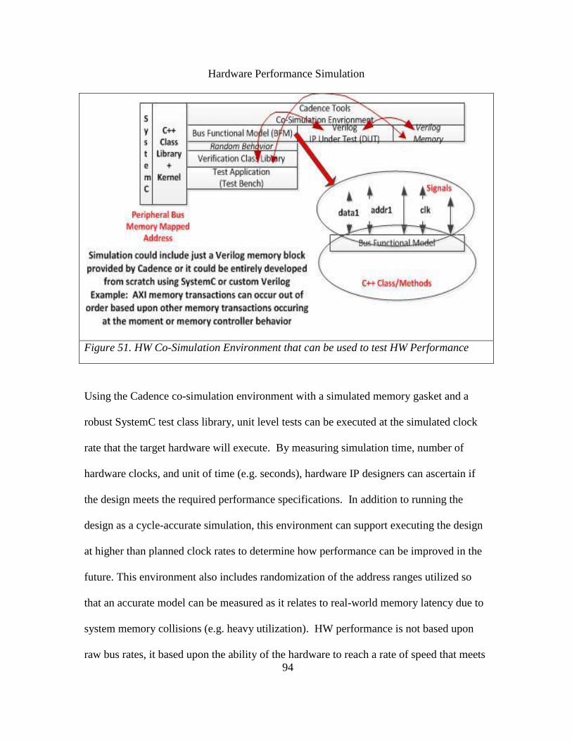
94
Hardware Performance Simulation
Figure 51. HW Co-Simulation Environment that can be used to test HW Performance
Using the Cadence co-simulation environment with a simulated memory gasket and a
robust SystemC test class library, unit level tests can be executed at the simulated clock
rate that the target hardware will execute. By measuring simulation time, number of
hardware clocks, and unit of time (e.g. seconds), hardware IP designers can ascertain if
the design meets the required performance specifications. In addition to running the
design as a cycle-accurate simulation, this environment can support executing the design
at higher than planned clock rates to determine how performance can be improved in the
future. This environment also includes randomization of the address ranges utilized so
that an accurate model can be measured as it relates to real-world memory latency due to
system memory collisions (e.g. heavy utilization). HW performance is not based upon
raw bus rates, it based upon the ability of the hardware to reach a rate of speed that meets

95
the minimum performance specifications. For example, a memory gasket can perform at
6.4GB/sec; however, it can never reach that because it can only support 3 memory
transactions at one time. This is because the memory bus interface being used will only
be used for a large number of relatively short memory transactions, not one large
transaction. Therefore, though the raw performance of the bus is impressive, it does not
meet the requirements because with only 3 transactions allowed in parallel, we are
limited to only a very small fraction of the maximum bandwidth.
This does not replace the testing of subsystems that interact with the hardware IP under
test. Connected subsystems must meet their performance specification and must be
tested to ensure their committed performance target is met when used as intended by the
end product user. Hardware can be designed to meet a performance specification, but the
preconditions and post conditions are important. If the only way the hardware is going to
meet its performance target is to use it in a way that would never occur in its actual use, it
should be considered compliant with the requirements.

96
CHAPTER 5
SUMMARY CONCLUSION
This thesis focused on furthering a new concept in regard to link layer communication as
it relates to wireless devices. I focused on how this proposed system would provide
support for the use of 802.11 and cellular protocol stacks. I also focused on the hardware
implementation (e.g. start of SoC design, functional decomposition) to support this new
link layer idea that wireless data frames are processed by hardware state machines (not by
software). In order for this occur, hardware functions and features must be in place to
ensure that wireless behavior such as roaming, RF communication methods, wired
network infrastructure support (VLAN/Proxy ARP/Routing) are provided. In Chapter 1
I focused on an introduction to the technology, some of the limitations, and similarities
between the two wireless standards. In Chapter 2 I focused on the link layer
communication mechanisms and an overview of the link layer communication model
between the cell controller and the base stations as well as some of the functional system
decomposition. Chapter 3 focused on the mobile device issues in regard to a review of
their state machine behavior, capabilities, and typical interactions with existing wireless
communication protocols. I further described how a cell controller would support these
devices as well as a small research effort in regard to RF signal estimation and PSD
derivation that might be implemented on mobile devices on behalf of the cell controller
(e.g. network side RF measurement request). Finally in Chapter 4 I reviewed some of the
hardware design, development, and verification methodologies that would be employed
to develop such a SoC design. This paper focused on the high level concepts. In order to

97
bring these concepts to practice, much more material is needed to fully define all
requirements, timing constraints, and further uncover additional design considerations.

98
REFERENCES
Barton, B. (2012, March 30). eUTRAN to UTRAN (4G to 3G). Retrieved March 20,
2014, from LTE and BEYOND: http://www.lteandbeyond.com/2012/03/few-last-articles-
were-about-handover.html
Wikipedia. (2014, February 24). Cellular data communication protocol. Retrieved March
15, 2014, From Wikipedia, the free encyclopedia:
https://en.wikipedia.org/wiki/Cellular_data_communication_protocol
Freescale. (2014, March 15). P4080: QorIQ P4080/P4040/P4081 Communications
Processors with Data Path. Retrieved March 15, 2014, From Freescale Semiconductor:
http://www.freescale.com/webapp/sps/site/prod_summary.jsp?code=P4080
Airstream. (2014, April 3). ACK Timeouts and the effects on distance. Retrieved March
1, 2014, From Airstream: http://www.air-stream.org/technical/ack-timeouts-and-effects-
distance-links
ShareTechnote. (2013, September 4). Handover LTE. Retrieved February 28, 2014,
From ShareTechnote: http://www.sharetechnote.com/html/Handover_LTE.html
Peter McGuiggan. (2004). GPRS in Practice. West Sussex, England: John Wiley & Sons.
James F. Kurose, Keith W. Ross. (2010). Computer Networking, Fifth Edition. Boston:
Pearson.
Steven M. Kay. (2010). Fundamentals of Statistical Signal Processing (Estimation
Theory). Hamilton in Castleton: Prentice-Hall.
Steven M. Kay. (2008). Fundamentals of Statistical Signal Processing (Detection
Theory). Troy: Prentice-Hall.
Douglas C. Montgomery. (2013). Design and Analysis of Experiments, Eighth Edition.
Hoboken: John Wiley & Sons.
Frank James, J.K., R.B. (2004), US Patent Application 20050157690. United
States/California
Cover, T. (1972). Admissibility properties of Gilbert’s encoding for unknown source
probabilities. IEEE Transactions on Information Theory, 18:216–217.

99
Krichevsky, R. (1998). Laplace’s law of succession and universal encoding. IEEE
Transactions on Information Theory, 44:296–303.
McDiarmid, C. (1989). On the method of bounded differences. In Surveys in
Combinatorics, pages 148–188. Cambridge University Press.
Miller, G. (1955). Note on the bias of information estimates. In Information theory in
psychology II-B, pages 95–100.
Nemenman, I., Shafee, F., and Bialek, W. (2002). Entropy and inference, revisited. NIPS,
14.
Paninski, L. (2003). Estimation of entropy and mutual information. Neural Computation,
15:1191–1253.
Paninski, L. (2004). Estimating entropy on m bins given fewer than m samples. IEEE
Transactions on Information Theory, 50:2200–2203.
Paninski, L. (2005). Variational minimax estimation of discrete distributions under KL
loss. Advances in Neural Information Processing Systems, 17.
Paninski, L. (2008). A coincidence-based test for uniformity given very sparsely-sampled
discrete data. IEEE Transactions on Information Theory, 54:4750–4755.
Paninski, L. and Yajima, M. (2008). Undersmoothed kernel entropy estimators. IEEE
Transactions on Information Theory, 54:4384–4388.
NIST. (2001, May 1) FIPS PUB 140-2. Security Requirements for Cryptographic
Modules. Federal Information Processing Standards Publication. Category: Security.
Subcategory: Cryptography.
NIST. (2012, February 16) Annex C: Approved Random Number Generators for FIPS
PUB 140-2, Security Requirements for Cryptographic Modules.

100
APPENDIX A
MATLAB PROGRAM AMPLITUDE/PHASE/FREQUENCY ESTIMATOR

101
% % Amplitude & Phase & Frequency unknown. % -Must estimate frequency using periodogram. % -Must estimate amplitude. % -Must estimate phase.
samples = 1000; N = 5; u0 = 0; phi = .25 *(2*pi); f0 = 0.25; A = 2; var0 =1;
%all_known_pd=zeros(samples,1); %all_known_pfa=zeros(samples,1); %energy_noise=zeros(samples,1);
%A_unknown_pd=zeros(samples,1); %A_unknown_pfa=zeros(samples,1);
%A_phi_unknown_pd=zeros(samples,1); %A_phi_unknown_pfa=zeros(samples,1);
all_unknown_pd=zeros(samples,1); all_unknown_pfa=zeros(samples,1);
wgn = zeros(samples,1); x0=zeros(samples,1); x1=zeros(samples,1); x=zeros(samples,1); freq_est=zeros(samples,1); phase_est=zeros(samples,1); a_est=zeros(samples,1);
for iter=1:samples;
wgn = u0 + (sqrt(var0)*randn(samples,1)); x0 = wgn;
for sig_iter=1:samples; x1(sig_iter) = wgn(sig_iter) + cos((2*pi*f0*sig_iter)+phi); end;
index = 1; sfreq=.005; efreq=.495; incfreq=.005;
i_freq = zeros(((efreq-sfreq)/incfreq)+2,1);
for freq=sfreq:incfreq:efreq;
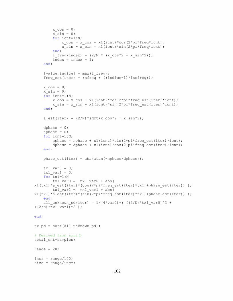
102
x_cos = 0; x_sin = 0; for icnt=1:N; x_cos = x_cos + x1(icnt)*cos(2*pi*freq*icnt); x_sin = x_sin + x1(icnt)*sin(2*pi*freq*icnt); end; i_freq(index) = (2/N * (x_cos^2 + x_sin^2)); index = index + 1; end;
[value,indice] = max(i_freq); freq_est(iter) = (sfreq + ((indice-1)*incfreq));
x_cos = 0; x_sin = 0; for icnt=1:N; x_cos = x_cos + x1(icnt)*cos(2*pi*freq_est(iter)*icnt); x_sin = x_sin + x1(icnt)*sin(2*pi*freq_est(iter)*icnt); end;
a_est(iter) = (2/N)*sqrt(x_cos^2 + x_sin^2);
dphase = 0; nphase = 0; for icnt=1:N; nphase = nphase + x1(icnt)*sin(2*pi*freq_est(iter)*icnt); dphase = dphase + x1(icnt)*cos(2*pi*freq_est(iter)*icnt); end;
phase_est(iter) = abs(atan(-nphase/dphase));
tx1_var0 = 0; tx1_var1 = 0; for tx1=1:N tx1_var0 = tx1_var0 + abs(
x1(tx1)*a_est(iter)*(cos(2*pi*freq_est(iter)*tx1)+phase_est(iter)) ); tx1_var1 = tx1_var1 + abs(
x1(tx1)*a_est(iter)*(sin(2*pi*freq_est(iter)*tx1)+phase_est(iter)) ); end; all_unknown_pd(iter) = 1/(4*var0)*( ((2/N)*tx1_var0)^2 +
((2/N)*tx1_var1)^2 );
end;
tx_pd = sort(all_unknown_pd);
% Derived from sort() total_cnt=samples;
range = 20;
incr = range/100; size = range/incr;

103
%Monte Carlo Solution pd_y=zeros(range/incr,7); engy_x=zeros(range/incr,7);
var_pd = var(all_unknown_pd);
pfa = 10^-1; for nplots=1:7;
index = 1; for iter=0: incr : range-.2;
pd_cnt=0;
nA = sqrt( ((2*var0)/N)*(10^(iter/10)) ); gamma = nA*(1/2)*chi2cdf((1-pfa),2);
for n=1:samples; if (all_unknown_pd(n) > gamma) pd_cnt = pd_cnt + 1; end; end;
pd_y(index,nplots) = pd_cnt/total_cnt; engy_x(index,nplots) = (range-.2) - iter;
index = index + 1; end;
pfa = pfa*10^-1; end;
plot(engy_x,pd_y);

104
APPENDIX B
MATLAB PROGRAM BURG PSD ESTIMATOR

105
%
%
% Burg PSD Estimator
%
%
% With & Without Noise
%
%
Fs=64;% Samples/sec
F01 = 10; %Hz
F02 = 11; %Hz
F03 = 25; %Hz
T1 = 1/F01;
T2 = 1/F02;
T3 = 1/F03;
UnitAmplitude = 1;
duration = 2; %length of simulation (sec)
samples = duration*Fs;
t=(1/Fs:1/Fs:duration)';
N = duration * Fs;
T = 1/Fs; %Sampling Interval
DBM = 0;
s1 = UnitAmplitude*sin(2*pi*F01*t);%Pure Signal
s2 = UnitAmplitude*sin(2*pi*F02*t);%Pure Signal
s3 = UnitAmplitude*sin(2*pi*F03*t);%Pure Signal
noise = rand(1,samples)';%noise added to signal
S = s1 + s2 + s3; %Combined Signals Without Noise
x1 = awgn(s1,0);%add WGN 0db SNR
x2 = awgn(s2,0);%add WGN 0db SNR
x3 = awgn(s3,0);%add WGN 0db SNR
X = x1 + x2 + x3; %Combined Signals With Noise
%plot (t,s3,t,x3); %Test Only
%plot(t,s3); %Test Only
for nextPlot = 1: 6
if (nextPlot < 4)
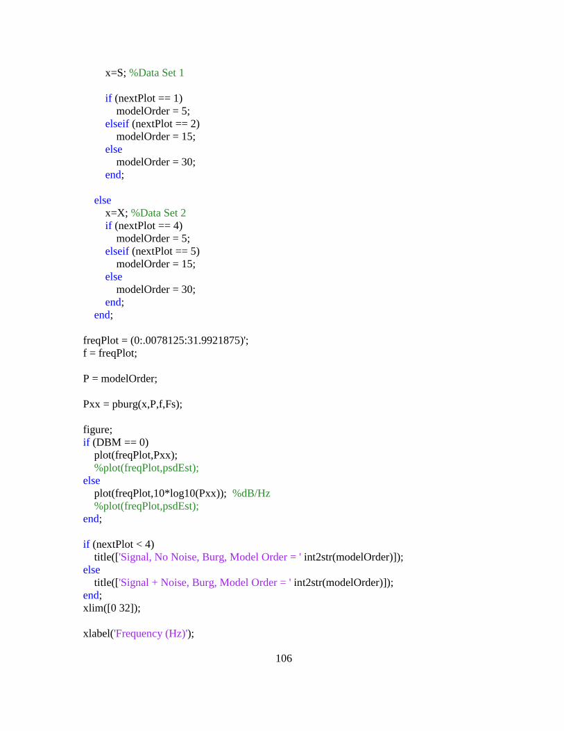
106
x=S; %Data Set 1
if (nextPlot == 1)
modelOrder = 5;
elseif (nextPlot == 2)
modelOrder = 15;
else
modelOrder = 30;
end;
else
x=X; %Data Set 2
if (nextPlot == 4)
modelOrder = 5;
elseif (nextPlot == 5)
modelOrder = 15;
else
modelOrder = 30;
end;
end;
freqPlot = (0:.0078125:31.9921875)';
f = freqPlot;
P = modelOrder;
Pxx = pburg(x,P,f,Fs);
figure;
if (DBM == 0)
plot(freqPlot,Pxx);
%plot(freqPlot,psdEst);
else
plot(freqPlot,10*log10(Pxx)); %dB/Hz
%plot(freqPlot,psdEst);
end;
if (nextPlot < 4)
title(['Signal, No Noise, Burg, Model Order = ' int2str(modelOrder)]);
else
title(['Signal + Noise, Burg, Model Order = ' int2str(modelOrder)]);
end;
xlim([0 32]);
xlabel('Frequency (Hz)');
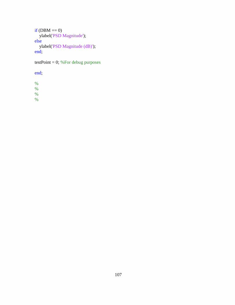
107
if (DBM == 0)
ylabel('PSD Magnitude');
else
ylabel('PSD Magnitude (dB)');
end;
testPoint = 0; %For debug purposes
end;
%
%
%
%

108
APPENDIX C
MATLAB PROGRAM BLACKMAN-TUKEY PSD ESTIMATOR

109
%
% Blackman-Tukey PSD Estimator
%
%
% With & Without Noise
%
%
Fs=64;% Samples/sec
F01 = 10; %Hz
F02 = 11; %Hz
F03 = 25; %Hz
T1 = 1/F01;
T2 = 1/F02;
T3 = 1/F03;
UnitAmplitude = 1;
duration = 2; %length of simulation (sec)
samples = duration*Fs;
t=(1/Fs:1/Fs:duration)';
N = duration * Fs;
T = 1/Fs; %Sampling Interval
s1 = UnitAmplitude*sin(2*pi*F01*t);%Pure Signal
s2 = UnitAmplitude*sin(2*pi*F02*t);%Pure Signal
s3 = UnitAmplitude*sin(2*pi*F03*t);%Pure Signal
noise = rand(1,samples)';%noise added to signal
S = s1 + s2 + s3; %Combined Signals Without Noise
x1 = awgn(s1,0);%add WGN 0db SNR
x2 = awgn(s2,0);%add WGN 0db SNR
x3 = awgn(s3,0);%add WGN 0db SNR
X = x1 + x2 + x3; %Combined Signals With Noise
%plot (t,s3,t,x3); %Test Only
%plot(t,s3); %Test Only
for nextPlot = 1: 6
if (nextPlot < 4)

110
x = S; %Without Noise
if (nextPlot == 1)
Lag = 10; %Without Noise -All Freq. Components visible
elseif (nextPlot == 2)
Lag = 20;
else
Lag = 70;
end;
M = Lag;
else
x = X; %With Noise
if (nextPlot == 4)
Lag = 10; %Without Noise -All Freq. Components visible
elseif (nextPlot == 5)
Lag = 20;
else
Lag = 70;
end;
M = Lag;
end;
Rxx2 = xcorr(x,x,M,'unbiased');
hammingW = hamming(2*M,'periodic');
%hammingW = hamming(2*M);
freq=0;
psdEst=zeros(1,300);
for k=1: 300 % 30Hz band in a .1 Hz interval
realM = -M;
for m=1: 2*M
psdEst(k) = psdEst(k) + (hammingW(m)*Rxx2(m)*exp(-1i*2*pi*T*realM*freq));
realM = realM + 1;
end;
psdEst(k) = T * psdEst(k);
freq = freq + .1;
end;
freqPlot = (0:.1:29.9)';
figure;
plot(freqPlot,real(psdEst));
%plot(freqPlot,10*log10(real(psdEst))); %dB/Hz
if (nextPlot < 4)
title(['Signal, no noise, Blackman-Tukey Plot Lag = ' int2str(Lag)]);

111
else
title(['Signal + noise, Blackman-Tukey Plot Lag = ' int2str(Lag)]);
end;
xlabel('Frequency (Hz)');
ylabel('PSD Magnitude');
end;
testPoint = 0; %For debug purposes

112
APPENDIX D
MATLAB PROGRAM COVARIANCE PSD ESTIMATOR
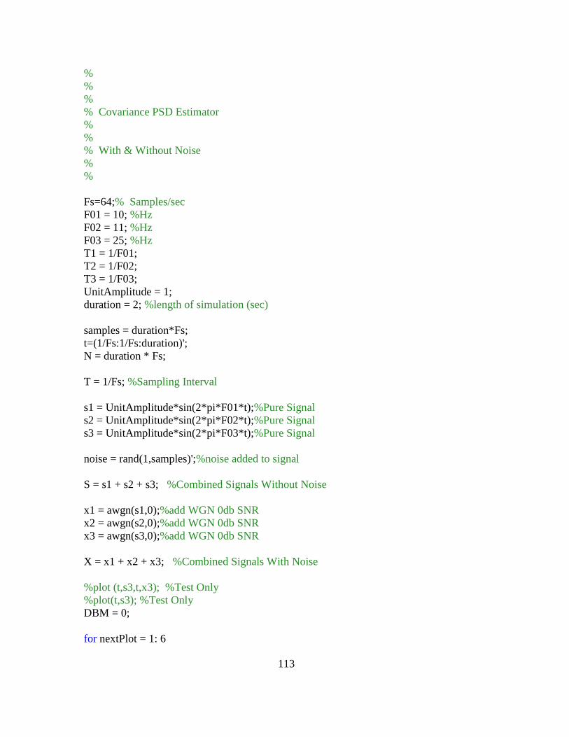
113
%
%
%
% Covariance PSD Estimator
%
%
% With & Without Noise
%
%
Fs=64;% Samples/sec
F01 = 10; %Hz
F02 = 11; %Hz
F03 = 25; %Hz
T1 = 1/F01;
T2 = 1/F02;
T3 = 1/F03;
UnitAmplitude = 1;
duration = 2; %length of simulation (sec)
samples = duration*Fs;
t=(1/Fs:1/Fs:duration)';
N = duration * Fs;
T = 1/Fs; %Sampling Interval
s1 = UnitAmplitude*sin(2*pi*F01*t);%Pure Signal
s2 = UnitAmplitude*sin(2*pi*F02*t);%Pure Signal
s3 = UnitAmplitude*sin(2*pi*F03*t);%Pure Signal
noise = rand(1,samples)';%noise added to signal
S = s1 + s2 + s3; %Combined Signals Without Noise
x1 = awgn(s1,0);%add WGN 0db SNR
x2 = awgn(s2,0);%add WGN 0db SNR
x3 = awgn(s3,0);%add WGN 0db SNR
X = x1 + x2 + x3; %Combined Signals With Noise
%plot (t,s3,t,x3); %Test Only
%plot(t,s3); %Test Only
DBM = 0;
for nextPlot = 1: 6
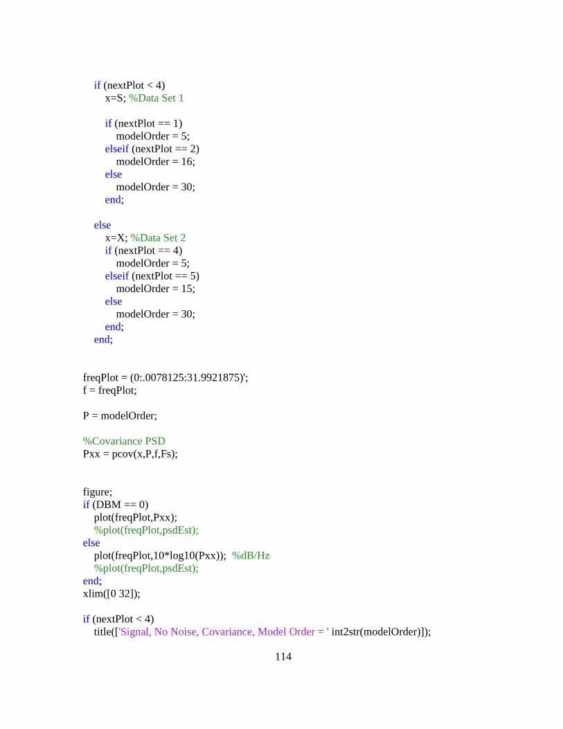
114
if (nextPlot < 4)
x=S; %Data Set 1
if (nextPlot == 1)
modelOrder = 5;
elseif (nextPlot == 2)
modelOrder = 16;
else
modelOrder = 30;
end;
else
x=X; %Data Set 2
if (nextPlot == 4)
modelOrder = 5;
elseif (nextPlot == 5)
modelOrder = 15;
else
modelOrder = 30;
end;
end;
freqPlot = (0:.0078125:31.9921875)';
f = freqPlot;
P = modelOrder;
%Covariance PSD
Pxx = pcov(x,P,f,Fs);
figure;
if (DBM == 0)
plot(freqPlot,Pxx);
%plot(freqPlot,psdEst);
else
plot(freqPlot,10*log10(Pxx)); %dB/Hz
%plot(freqPlot,psdEst);
end;
xlim([0 32]);
if (nextPlot < 4)
title(['Signal, No Noise, Covariance, Model Order = ' int2str(modelOrder)]);

115
else
title(['Signal + Noise, Covariance, Model Order = ' int2str(modelOrder)]);
end;
xlabel('Frequency (Hz)');
if (DBM == 0)
ylabel('PSD Magnitude');
else
ylabel('PSD Magnitude (dB)');
end;
testPoint = 0; %For debug purposes
end;

116
APPENDIX E
MATLAB PROGRAM MODIFIED COVARIANCE PSD ESTIMATOR
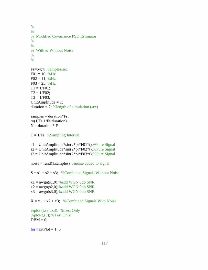
117
%
%
% Modified Covariance PSD Estimator
%
%
% With & Without Noise
%
%
Fs=64;% Samples/sec
F01 = 10; %Hz
F02 = 11; %Hz
F03 = 25; %Hz
T1 = 1/F01;
T2 = 1/F02;
T3 = 1/F03;
UnitAmplitude = 1;
duration = 2; %length of simulation (sec)
samples = duration*Fs;
t=(1/Fs:1/Fs:duration)';
N = duration * Fs;
T = 1/Fs; %Sampling Interval
s1 = UnitAmplitude*sin(2*pi*F01*t);%Pure Signal
s2 = UnitAmplitude*sin(2*pi*F02*t);%Pure Signal
s3 = UnitAmplitude*sin(2*pi*F03*t);%Pure Signal
noise = rand(1,samples)';%noise added to signal
S = s1 + s2 + s3; %Combined Signals Without Noise
x1 = awgn(s1,0);%add WGN 0db SNR
x2 = awgn(s2,0);%add WGN 0db SNR
x3 = awgn(s3,0);%add WGN 0db SNR
X = x1 + x2 + x3; %Combined Signals With Noise
%plot (t,s3,t,x3); %Test Only
%plot(t,s3); %Test Only
DBM = 0;
for nextPlot = 1: 6

118
if (nextPlot < 4)
x=S; %Data Set 1
if (nextPlot == 1)
modelOrder = 5;
elseif (nextPlot == 2)
modelOrder = 15;
else
modelOrder = 30;
end;
else
x=X; %Data Set 2
if (nextPlot == 4)
modelOrder = 5;
elseif (nextPlot == 5)
modelOrder = 15;
else
modelOrder = 30;
end;
end;
freqPlot = (0:.0078125:31.9921875)';
f = freqPlot;
P = modelOrder;
%Modified Covariance PSD
Pxx = pmcov(x,P,f,Fs);
figure;
if (DBM == 0)
plot(freqPlot,Pxx);
%plot(freqPlot,psdEst);
else
plot(freqPlot,10*log10(Pxx)); %dB/Hz
%plot(freqPlot,psdEst);
end;
if (nextPlot < 4)
title(['Signal, No Noise, Modified Covariance, Model Order = ' int2str(modelOrder)]);
else
title(['Signal + Noise, Modified Covariance, Model Order = ' int2str(modelOrder)]);
end;
xlabel('Frequency (Hz)');

119
xlim([0 32]);
if (DBM == 0)
ylabel('PSD Magnitude');
else
ylabel('PSD Magnitude (dB)');
end;
testPoint = 0; %For debug purposes
end;

120
APPENDIX F
MATLAB PROGRAM MUSIC PSD ESTIMATOR
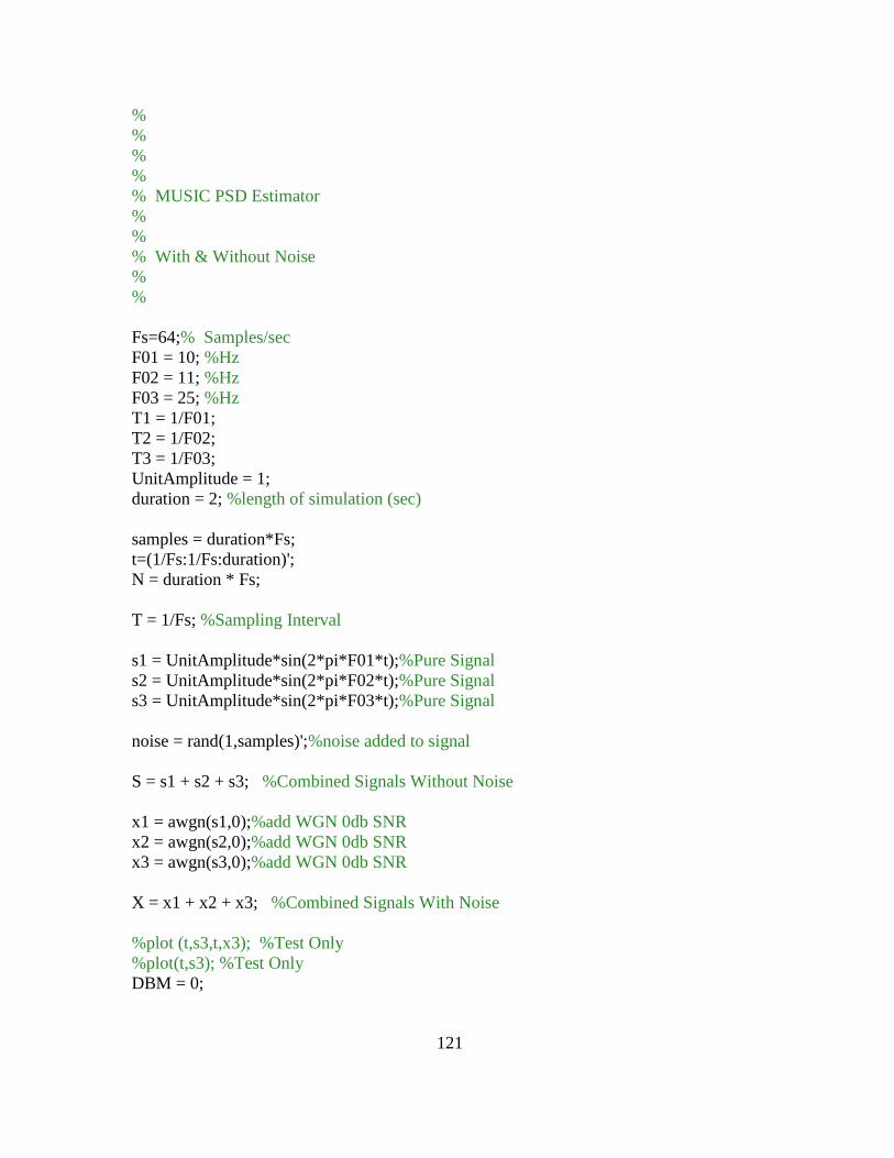
121
%
%
%
%
% MUSIC PSD Estimator
%
%
% With & Without Noise
%
%
Fs=64;% Samples/sec
F01 = 10; %Hz
F02 = 11; %Hz
F03 = 25; %Hz
T1 = 1/F01;
T2 = 1/F02;
T3 = 1/F03;
UnitAmplitude = 1;
duration = 2; %length of simulation (sec)
samples = duration*Fs;
t=(1/Fs:1/Fs:duration)';
N = duration * Fs;
T = 1/Fs; %Sampling Interval
s1 = UnitAmplitude*sin(2*pi*F01*t);%Pure Signal
s2 = UnitAmplitude*sin(2*pi*F02*t);%Pure Signal
s3 = UnitAmplitude*sin(2*pi*F03*t);%Pure Signal
noise = rand(1,samples)';%noise added to signal
S = s1 + s2 + s3; %Combined Signals Without Noise
x1 = awgn(s1,0);%add WGN 0db SNR
x2 = awgn(s2,0);%add WGN 0db SNR
x3 = awgn(s3,0);%add WGN 0db SNR
X = x1 + x2 + x3; %Combined Signals With Noise
%plot (t,s3,t,x3); %Test Only
%plot(t,s3); %Test Only
DBM = 0;
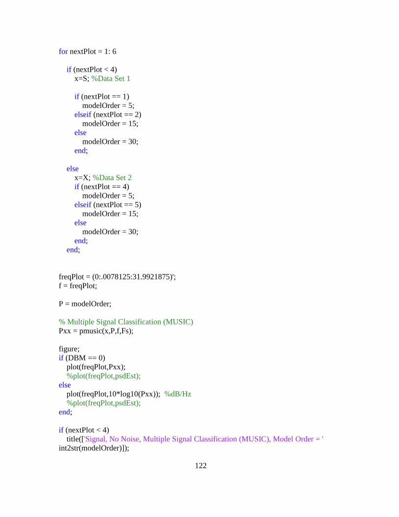
122
for nextPlot = 1: 6
if (nextPlot < 4)
x=S; %Data Set 1
if (nextPlot == 1)
modelOrder = 5;
elseif (nextPlot == 2)
modelOrder = 15;
else
modelOrder = 30;
end;
else
x=X; %Data Set 2
if (nextPlot == 4)
modelOrder = 5;
elseif (nextPlot == 5)
modelOrder = 15;
else
modelOrder = 30;
end;
end;
freqPlot = (0:.0078125:31.9921875)';
f = freqPlot;
P = modelOrder;
% Multiple Signal Classification (MUSIC)
Pxx = pmusic(x,P,f,Fs);
figure;
if (DBM == 0)
plot(freqPlot,Pxx);
%plot(freqPlot,psdEst);
else
plot(freqPlot,10*log10(Pxx)); %dB/Hz
%plot(freqPlot,psdEst);
end;
if (nextPlot < 4)
title(['Signal, No Noise, Multiple Signal Classification (MUSIC), Model Order = '
int2str(modelOrder)]);
123
else
title(['Signal + Noise, Multiple Signal Classification (MUSIC), Model Order = '
int2str(modelOrder)]);
end;
xlabel('Frequency (Hz)');
if (DBM == 0)
ylabel('PSD Magnitude');
else
ylabel('PSD Magnitude (dB)');
end;
testPoint = 0; %For debug purposes
end;

124
APPENDIX G
MATLAB PROGRAM WELCH PSD ESTIMATOR

125
%
%
%
% Welch PSD Estimator
%
%
% With & Without Noise
%
%
Fs=64;% Samples/sec
F01 = 10; %Hz
F02 = 11; %Hz
F03 = 25; %Hz
T1 = 1/F01;
T2 = 1/F02;
T3 = 1/F03;
UnitAmplitude = 1;
duration = 2; %length of simulation (sec)
samples = duration*Fs;
t=(1/Fs:1/Fs:duration)';
N = duration * Fs;
T = 1/Fs; %Sampling Interval
s1 = UnitAmplitude*sin(2*pi*F01*t);%Pure Signal
s2 = UnitAmplitude*sin(2*pi*F02*t);%Pure Signal
s3 = UnitAmplitude*sin(2*pi*F03*t);%Pure Signal
noise = rand(1,samples)';%noise added to signal
S = s1 + s2 + s3; %Combined Signals Without Noise
x1 = awgn(s1,0);%add WGN 0db SNR
x2 = awgn(s2,0);%add WGN 0db SNR
x3 = awgn(s3,0);%add WGN 0db SNR
X = x1 + x2 + x3; %Combined Signals With Noise
%plot (t,s3,t,x3); %Test Only
%plot(t,s3); %Test Only
d = 32;
for nextPlot = 1: 6
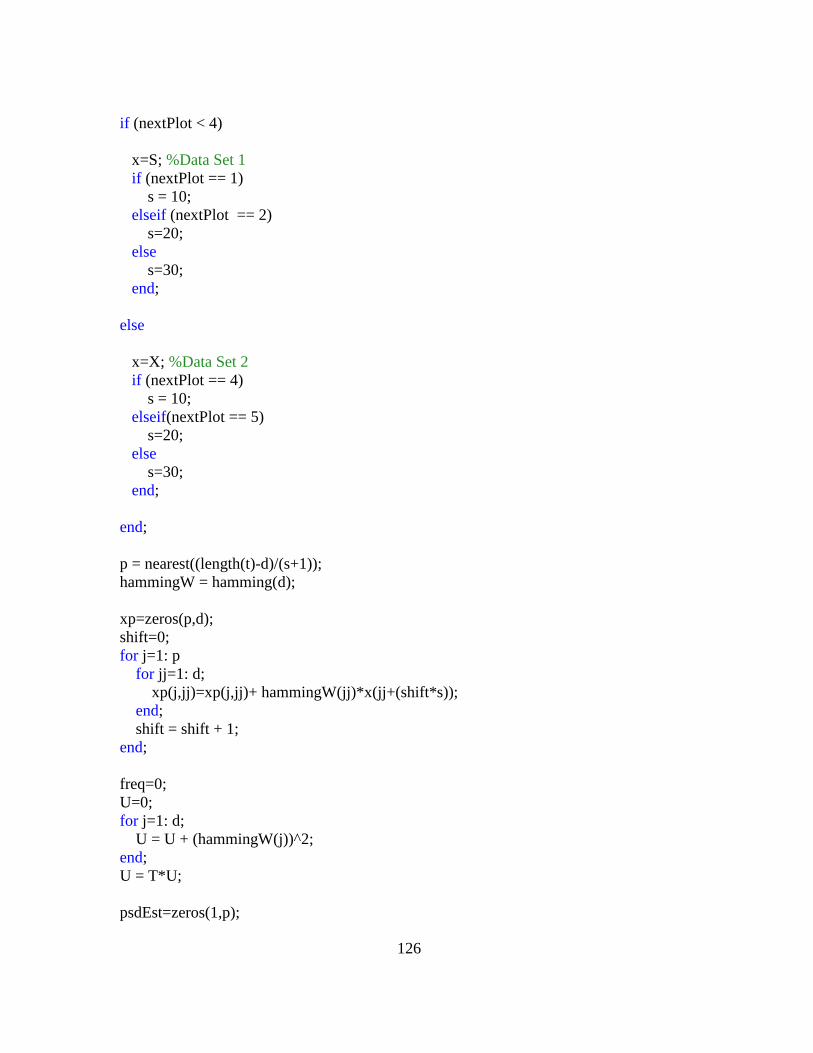
126
if (nextPlot < 4)
x=S; %Data Set 1
if (nextPlot == 1)
s = 10;
elseif (nextPlot == 2)
s=20;
else
s=30;
end;
else
x=X; %Data Set 2
if (nextPlot == 4)
s = 10;
elseif(nextPlot == 5)
s=20;
else
s=30;
end;
end;
p = nearest((length(t)-d)/(s+1));
hammingW = hamming(d);
xp=zeros(p,d);
shift=0;
for j=1: p
for jj=1: d;
xp(j,jj)=xp(j,jj)+ hammingW(jj)*x(jj+(shift*s));
end;
shift = shift + 1;
end;
freq=0;
U=0;
for j=1: d;
U = U + (hammingW(j))^2;
end;
U = T*U;
psdEst=zeros(1,p);

127
WelchpsdEst=zeros(1,300);
for kk=1 : 300; % 30Hz band in a .1 Hz interval
accumPSD=0;
for k=1: p
for m=1: d
psdEst(k) = psdEst(k) + (xp(k,m)*exp(-1i*2*pi*T*m*freq));
end;
psdEst(k) = (1/(U*d*T))*(abs((T * psdEst(k))))^2;
accumPSD = accumPSD + psdEst(k);
end;
WelchpsdEst(kk) = accumPSD/p;
freq = freq + .1;
end;
%pwelch(x,d,d-s,length(x),Fs,'onesided'); %Hamming window
freqPlot = (0:.1:29.9)';
figure;
plot(freqPlot,WelchpsdEst);
%plot(freqPlot,10*log10(WelchpsdEst)); %dB/Hz
if (nextPlot < 4)
title(['Signal, no noise, Welch Periodogram, sample shift = ' int2str(s)]);
else
title(['Signal + noise, Welch Periodogram, sample shift = ' int2str(s)]);
end;
xlabel('Frequency (Hz)');
ylabel('PSD Magnitude');
testPoint = 0; %For debug purposes
end;

128
APPENDIX H
MATLAB PROGRAM YULE-WALKER PSD ESTIMATOR

129
%
%
%
% Yule-Walker PSD Estimator
%
%
% With & Without Noise
%
%
Fs=64;% Samples/sec
F01 = 10; %Hz
F02 = 11; %Hz
F03 = 25; %Hz
T1 = 1/F01;
T2 = 1/F02;
T3 = 1/F03;
UnitAmplitude = 1;
duration = 2; %length of simulation (sec)
samples = duration*Fs;
t=(1/Fs:1/Fs:duration)';
N = duration * Fs;
T = 1/Fs; %Sampling Interval
s1 = UnitAmplitude*sin(2*pi*F01*t);%Pure Signal
s2 = UnitAmplitude*sin(2*pi*F02*t);%Pure Signal
s3 = UnitAmplitude*sin(2*pi*F03*t);%Pure Signal
noise = rand(1,samples)';%noise added to signal
S = s1 + s2 + s3; %Combined Signals Without Noise
x1 = awgn(s1,0);%add WGN 0db SNR
x2 = awgn(s2,0);%add WGN 0db SNR
x3 = awgn(s3,0);%add WGN 0db SNR
X = x1 + x2 + x3; %Combined Signals With Noise
%plot (t,s3,t,x3); %Test Only
%plot(t,s3); %Test Only
%s=3;
%s=10;
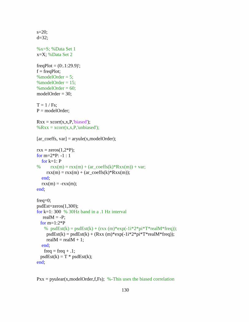
130
s=20;
d=32;
%x=S; %Data Set 1
x=X; %Data Set 2
freqPlot = (0:.1:29.9)';
f = freqPlot;
%modelOrder = 5;
%modelOrder = 15;
%modelOrder = 60;
modelOrder = 30;
T = 1 / Fs;
P = modelOrder;
Rxx = xcorr(x,x,P,'biased');
%Rxx = xcorr(x,x,P,'unbiased');
[ar_coeffs, var] = aryule(x,modelOrder);
rxx = zeros(1,2*P);
for m=2*P: -1 : 1
for k=1: P
% rxx(m) = rxx(m) + (ar_coeffs(k)*Rxx(m)) + var;
rxx(m) = rxx(m) + (ar_coeffs(k)*Rxx(m));
end;
rxx(m) = -rxx(m);
end;
freq=0;
psdEst=zeros(1,300);
for k=1: 300 % 30Hz band in a .1 Hz interval
realM = -P;
for m=1:2*P
% psdEst(k) = psdEst(k) + (rxx (m)*exp(-1i*2*pi*T*realM*freq));
psdEst(k) = psdEst(k) + (Rxx (m)*exp(-1i*2*pi*T*realM*freq));
realM = realM + 1;
end;
freq = freq + .1;
psdEst(k) = T * psdEst(k);
end;
Pxx = pyulear(x,modelOrder,f,Fs); %-This uses the biased correlation

131
% estimate only.
%-The unbiased correlation estimate can
% cause unstable solutions (e.g.outside
% the unit circle
%plot(freqPlot,real(psdEst));
plot(freqPlot,Pxx);
%plot(freqPlot,10*log10(Pxx)); %dB/Hz
title(['Yule-Walker, Biased, Model Order = ' int2str(modelOrder)]);
xlabel('Frequency (Hz)');
ylabel('PSD Magnitude');
testPoint = 0; %For debug purposes
end;
%
Related Documents