New Mechanism for a 3 DOF Exoskeleton Hip Joint with Five Revolute and Two Prismatic Joints Jonas Beil and Tamim Asfour Institute for Anthropomatics and Robotics Karlsruhe Institute of Technology, Karlsruhe, Germany Abstract—We present a new exoskeleton hip design rep- resenting the human hip ball joint by five revolute and two prismatic joints. The goal of the design is to increase wearing comfort and torque transmission by reducing misalignments between the human’s and the exoskeleton’s joint with a self- aligning yaw axis in the transverse plane. The required ranges of motions and joint velocities for the hip joint design were identified based on motion capture data consisting of 828 motion recordings of 26 different subjects. We present the kinematics of a new hip joint with five revolute and two prismatic joints and its first 3D printed prototype. For the experimental evaluation we focused on measuring interaction forces between the subject and the exoskeleton at the back, pelvis and thigh with different kinematic configurations. The results indicate that interaction forces between exoskeleton and user are reduced by the new hip exoskeleton. I. INTRODUCTION Recently, considerable research efforts have been made in the area of exoskeleton development to augment human per- formance in daily and working environments. When design- ing such systems, wearability and comfort are key require- ments which must be addressed to enhance the acceptance of such assistive devices by their wearer. Application scenarios in daily living or working activities demand devices that can be used for hours without discomfort or skin abrasions caused by micro or macro misalignments between the user and the exoskeleton hip axes [1]. A self-aligning design using supplementary joints is there- fore beneficial to adjust the exoskeleton joint axis with the users hip instantaneous centers of rotation (ICR). Misalign- ments occurring at the hip also propagate to the knee and ankle joints or vice versa and decrease the efficiency of actuators and interfaces. To this end, it is important to design misalignment-free hip joints for lower limb exoskeletons. In this work, we present a novel design for an exoskeleton hip joint which allows such adjustments. Exoskeletons like Mina [2], eLegs [3] or HAL [4] only have either one degree of freedom (DOF) for hip flexion/ex- tension or two DOF adding hip abduction/adduction. Other devices like the Mindwalker exoskeleton [5], the lower body exoskeleton presented in [6] or the XOR2 [7] add a revolute joint between the roll and pitch joint to support hip rotation, accepting macro misalignments between the ICRs for this DOF. This macro misalignment is reduced in designs like the IHMC mobility assist exoskeleton [8] or the BLERE [9], which use a curved bearing to locate the center of rotation Fig. 1. 3D printed prototype of the proposed hip joint of a lower limb exoskeleton approximately at the user’s hip joint. Pons [10] and Cempini et. al. [11] propose additional joints to create self-aligning wearable devices that are comfortable and easy to use. The inter-subject variability of the human musculo-skeletal sys- tem, articulation and soft tissue deformation impede device designs that correctly align the axis of the human body and the mechanism. Usually, macro misalignments are reduced by manual adaptable mechanism to regulate link length and are com- bined with flexible attachments or additional passive joints at the physical Human Robot Interface (pHRI). In [12], the authors added a passive sliding and rotational adjustment to an orthotic shell, interfacing an assistive hip orthosis with the users thigh. Supplementary joints are also used in exoskele- ton devices for the upper body to self-align the wrist and forearm joints [13] or the elbow [14]. This paper presents a hip exoskeleton structure using supplementary joints to self- align to the user yaw axis in the transverse plane and aims to be integrated in an augmenting assistive device. Section II describes the requirements for the system resulting from human hip anatomy and human motion analysis. Section III explains the chosen kinematics and design of the prototype. Experimental evaluation of the design with different kine-

Welcome message from author
This document is posted to help you gain knowledge. Please leave a comment to let me know what you think about it! Share it to your friends and learn new things together.
Transcript
New Mechanism for a 3 DOF Exoskeleton Hip Jointwith Five Revolute and Two Prismatic Joints
Jonas Beil and Tamim AsfourInstitute for Anthropomatics and Robotics
Karlsruhe Institute of Technology, Karlsruhe, Germany
Abstract— We present a new exoskeleton hip design rep-resenting the human hip ball joint by five revolute and twoprismatic joints. The goal of the design is to increase wearingcomfort and torque transmission by reducing misalignmentsbetween the human’s and the exoskeleton’s joint with a self-aligning yaw axis in the transverse plane. The required rangesof motions and joint velocities for the hip joint design wereidentified based on motion capture data consisting of 828 motionrecordings of 26 different subjects. We present the kinematics ofa new hip joint with five revolute and two prismatic joints andits first 3D printed prototype. For the experimental evaluationwe focused on measuring interaction forces between the subjectand the exoskeleton at the back, pelvis and thigh with differentkinematic configurations. The results indicate that interactionforces between exoskeleton and user are reduced by the newhip exoskeleton.
I. INTRODUCTION
Recently, considerable research efforts have been made inthe area of exoskeleton development to augment human per-formance in daily and working environments. When design-ing such systems, wearability and comfort are key require-ments which must be addressed to enhance the acceptance ofsuch assistive devices by their wearer. Application scenariosin daily living or working activities demand devices thatcan be used for hours without discomfort or skin abrasionscaused by micro or macro misalignments between the userand the exoskeleton hip axes [1].
A self-aligning design using supplementary joints is there-fore beneficial to adjust the exoskeleton joint axis with theusers hip instantaneous centers of rotation (ICR). Misalign-ments occurring at the hip also propagate to the knee andankle joints or vice versa and decrease the efficiency ofactuators and interfaces. To this end, it is important to designmisalignment-free hip joints for lower limb exoskeletons. Inthis work, we present a novel design for an exoskeleton hipjoint which allows such adjustments.
Exoskeletons like Mina [2], eLegs [3] or HAL [4] onlyhave either one degree of freedom (DOF) for hip flexion/ex-tension or two DOF adding hip abduction/adduction. Otherdevices like the Mindwalker exoskeleton [5], the lower bodyexoskeleton presented in [6] or the XOR2 [7] add a revolutejoint between the roll and pitch joint to support hip rotation,accepting macro misalignments between the ICRs for thisDOF. This macro misalignment is reduced in designs likethe IHMC mobility assist exoskeleton [8] or the BLERE [9],which use a curved bearing to locate the center of rotation
Fig. 1. 3D printed prototype of the proposed hip joint of a lower limbexoskeleton
approximately at the user’s hip joint. Pons [10] and Cempiniet. al. [11] propose additional joints to create self-aligningwearable devices that are comfortable and easy to use. Theinter-subject variability of the human musculo-skeletal sys-tem, articulation and soft tissue deformation impede devicedesigns that correctly align the axis of the human body andthe mechanism.
Usually, macro misalignments are reduced by manualadaptable mechanism to regulate link length and are com-bined with flexible attachments or additional passive jointsat the physical Human Robot Interface (pHRI). In [12], theauthors added a passive sliding and rotational adjustment toan orthotic shell, interfacing an assistive hip orthosis with theusers thigh. Supplementary joints are also used in exoskele-ton devices for the upper body to self-align the wrist andforearm joints [13] or the elbow [14]. This paper presents ahip exoskeleton structure using supplementary joints to self-align to the user yaw axis in the transverse plane and aimsto be integrated in an augmenting assistive device. SectionII describes the requirements for the system resulting fromhuman hip anatomy and human motion analysis. Section IIIexplains the chosen kinematics and design of the prototype.Experimental evaluation of the design with different kine-
matic configurations and the force-based sensor system formeasuring interaction forces between the exoskeleton and theuser are presented in Section IV. Section V concludes thepaper.
II. DESIGN REQUIREMENTS OF A HIP EXOSKELETON
The human hip joint is a ball and socket joint with convexon concave or concave on convex movement characteristics[15]. Translational motions between the femoral head andthe acetabulum is minimized by the bone structure and softtissue support when rotating in the sagittal, transverse orfrontal plane. Though the translational motions are verysmall, differences in the musculoskeletal system as well asother inter-subject body characteristics (height, body massindex, age) should be compensated by a flexible mechanicaldesign. According to the German DIN Norm [16], the 5to 95 percentile of hip width of adults aged between 18and 65 amount 340 to 400 mm when standing and 350to 460 mm while sitting. Considering exoskeleton design,easy to manipulate mechanisms compensating body widthand height in the transverse and frontal body plane have tobe included for offline adjustment.
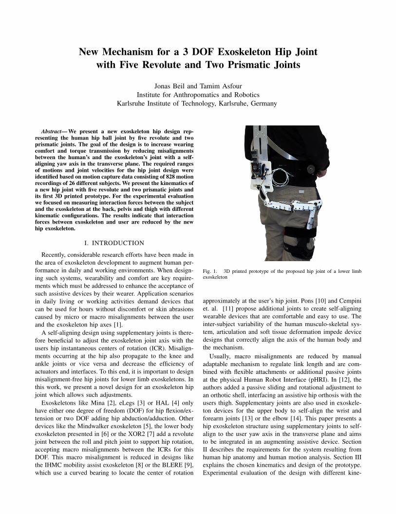
Fig. 2. Assumptions for hip rotation in transverse plane (top view).
When rotating the leg in the transverse plane, we assumethat the point at the outside pelvis created by the pitch axisand the pelvis skin (PA) performs a circular movement withcenter HC, radius rPA and angle φ which should also beperformed by the exoskeleton yaw axis. If the yaw jointmechanism is not positioned after the pitch joint like in[9] but between roll and pitch, application points at theback (RA) and the side pelvis (PA) vary from user to user(see Figure 2). Therefore, it is important for the design toallow positioning the pitch joint’s center of rotation suchthat the equations in Equation (1) are fulfilled. Assemblingthe yaw mechanism at the leg could constrain future kneejoint mechanisms or attachment points of actuators and istherefore avoided in this work.
PAx = HCx + rPA · cos(φ) (1)PAy = HCy + rPA · sin(φ)
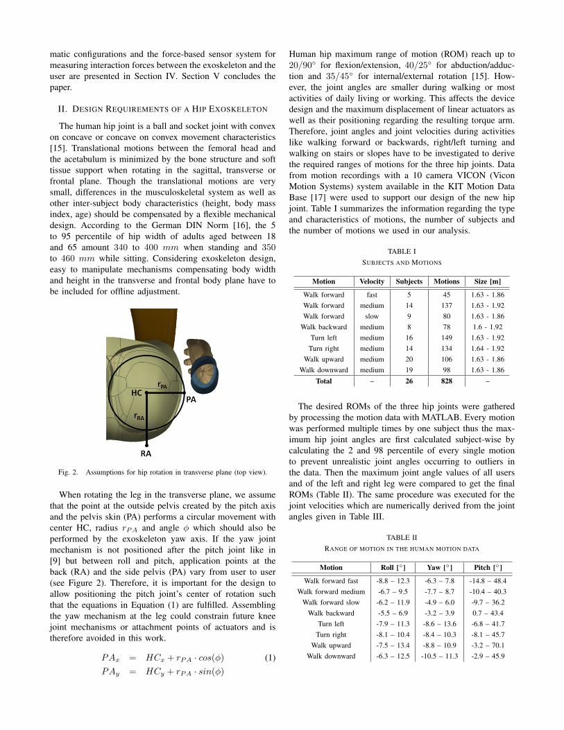
Human hip maximum range of motion (ROM) reach up to20/90◦ for flexion/extension, 40/25◦ for abduction/adduc-tion and 35/45◦ for internal/external rotation [15]. How-ever, the joint angles are smaller during walking or mostactivities of daily living or working. This affects the devicedesign and the maximum displacement of linear actuators aswell as their positioning regarding the resulting torque arm.Therefore, joint angles and joint velocities during activitieslike walking forward or backwards, right/left turning andwalking on stairs or slopes have to be investigated to derivethe required ranges of motions for the three hip joints. Datafrom motion recordings with a 10 camera VICON (ViconMotion Systems) system available in the KIT Motion DataBase [17] were used to support our design of the new hipjoint. Table I summarizes the information regarding the typeand characteristics of motions, the number of subjects andthe number of motions we used in our analysis.
TABLE ISUBJECTS AND MOTIONS
Motion Velocity Subjects Motions Size [m]
Walk forward fast 5 45 1.63 - 1.86Walk forward medium 14 137 1.63 - 1.92Walk forward slow 9 80 1.63 - 1.86
Walk backward medium 8 78 1.6 - 1.92Turn left medium 16 149 1.63 - 1.92
Turn right medium 14 134 1.64 - 1.92Walk upward medium 20 106 1.63 - 1.86
Walk downward medium 19 98 1.63 - 1.86
Total – 26 828 –
The desired ROMs of the three hip joints were gatheredby processing the motion data with MATLAB. Every motionwas performed multiple times by one subject thus the max-imum hip joint angles are first calculated subject-wise bycalculating the 2 and 98 percentile of every single motionto prevent unrealistic joint angles occurring to outliers inthe data. Then the maximum joint angle values of all usersand of the left and right leg were compared to get the finalROMs (Table II). The same procedure was executed for thejoint velocities which are numerically derived from the jointangles given in Table III.
TABLE IIRANGE OF MOTION IN THE HUMAN MOTION DATA
Motion Roll [◦] Yaw [◦] Pitch [◦]
Walk forward fast -8.8 – 12.3 -6.3 – 7.8 -14.8 – 48.4Walk forward medium -6.7 – 9.5 -7.7 – 8.7 -10.4 – 40.3
Walk forward slow -6.2 – 11.9 -4.9 – 6.0 -9.7 – 36.2Walk backward -5.5 – 6.9 -3.2 – 3.9 0.7 – 43.4
Turn left -7.9 – 11.3 -8.6 – 13.6 -6.8 – 41.7Turn right -8.1 – 10.4 -8.4 – 10.3 -8.1 – 45.7
Walk upward -7.5 – 13.4 -8.8 – 10.9 -3.2 – 70.1Walk downward -6.3 – 12.5 -10.5 – 11.3 -2.9 – 45.9

TABLE IIIREQUIRED JOINT VELOCITIES CALCULATED FROM THE MOTION DATA
Motion Roll[rads
]Yaw
[rads
]Pitch
[rads
]Walk forward fast -1.14 – 0.93 -1.54 – 1.34 -2.80 – 3.75
Walk forward medium -0.75 – 0.86 -1.33 – 1.31 -1.61 – 2.65Walk forward slow -0.68 – 0.65 -0.78 – 0.87 -1.08 – 1.99
Walk backward -0.58 – 0.48 -0.53 – 0.50 -2.08 – 1.17Turn left -1.07 – 0.75 -1.85 – 1.73 -1.61 – 2.73
Turn right -0.78 – 0.88 -1.67 – 1.51 -1.62 – 2.59Walk upward -0.70 – 0.92 -1.27 – 1.19 -2.06 – 3.07
Walk downward -0.94 – 0.92 -1.49 – 1.46 -1.91 – 2.15
A Positive roll angle corresponds to hip abduction, positiveyaw angle to external rotation and positive pitch angle to hipflexion. Gait speed was determined by the recorded subjectwho was asked to perform a fast, medium or slow walkingmotion. The analysis indicates the broad range of anglesbetween different motions and summarizes to -8.8 – 13.4 ◦
for the roll, -10.5 – 13.6 ◦ for the yaw and -14.8 – 100 ◦
(to allow sitting with the exoskeleton) for the pitch DOF.The joint velocities vary from -1.14 – 0.93 rad/s, -1.85 –1.73 rad/s and -2.8 – 3.75 rad/s in the aforementioneddirections. The hip joint construction should meet at leastthe ROMs derived from the analysis.
In our design, we envision a rate of assistance of half bodyweight of a 80 kg person per leg, i.e. 40 kg, which leadsto expected torques of 50 Nm in frontal plane, 8 Nm intransverse plane and 60 Nm in sagittal plane according to[15].
III. DESIGN OF THE HIP EXOSKELETON
A. Kinematics
To fulfill the requirements derived in section II a non-anthropomorphic exoskeleton kinematic structure is pro-posed, consisting of revolute joints in the roll and pitchaxis and a combination of three revolute and two prismaticjoints for the yaw axis. The kinematics are schematicallyillustrated in Figure 3 and are described in standard Denavit-Hartenberg (DH) parameters shown in Table IV. Origin O isthe beginning of the chain, and is positioned on the sagittalplane of the human on the back plate which is connected tothe backpack (Stihl RTS-HT, Waiblingen) worn by the user.Coordinate system L9 coincides with the last link connectingthe exoskeleton to the users thigh.
The roll axis is aligned by hand using eccentric clamps(Heinrich Kipp Werk KG, Sulz am Neckar), adjusting theposition of L1 in frontal and transverse plane according tothe range specified in Section II. A high precision doublerow angular ball bearing (30/85 2RS, SBN Walzlager GmbH& Co. KG, Schonenberg-Kubelberg) simultaneously capturesthrust and radial loads and is used in all revolute joints of thehip design. Taking motion analysis into account the ROM ofthe roll joint is limited to ±20 ◦.
The yaw joint (L3 − L7) is designed as a serial chain ofthree revolute and two prismatic (LWRE 3075, SKF GmbH,
Fig. 3. Kinematic structure with coordinate systems in the different joints,which are used to determine the DH-parameter.
TABLE IVDH PARAMETERS OF THE HIP DESIGN
Link Angle θi Twist αi Length ai Disp di
L1 0 0 0 34.5 + d1
L2 −90◦ 90◦ 74.5 62.5L3 90◦ + θ3 −90◦ 31.5 0L4 90◦ + θ4 90◦ 0 0L5 0 -90◦ 30.5 97.5 + d5
L6 θ6 90◦ 0 0L7 0 −90◦ 30.5 97.5 + d7
L8 −90◦ + θ8 90◦ 37.5 0L9 90◦ + θ8 0 80 0
Schweinfurt) joints around the user’s body to guarantee aflexible device which can be worn by a broad range ofpeople with different body dimensions, hip kinematics andarticulation. The combination of revolute and prismatic jointsallows the positioning of the pitch axis moving on a circlearound the hip center.
Due to the low maximum torque (0.2 Nm/kg) and power(0.16 W/kg) [15] during walking, we believe that actuationof the joint is not essential but passive parallel elasticelements at the prismatic bearings can support the user whilewalking. The first prototype therefore uses springs connectedat both ends of the prismatic bearings, applying force indirection of their zero position preventing uncontrolled jointmovement and apply a small amount of torque contrary topropelling torque. Although the prototype is not actuated yet,the prismatic and revolute bearings were chosen to supportthe loads resulting of a weight of 80 kg.
To derive the ROM for the yaw joint, the DH-parameterswere used to reach the position of PA (calculated withEquation 1) with angles between 10 − 60◦ for θ3, θ5 andθ7 and a displacement of 0 − 60 mm for d4 and d6 usingMATLAB. Allowing free movement of all revolute jointsleads to indefinite kinematics resulting in multiple jointconfigurations for one position of PA. Taking different humanbody characteristics into account, radius rPA was increased

Fig. 4. Calculated range of motion of the exoskeleton hip yaw axis varyingrPA.
starting from 80 mm until the minimum joint angle crosses±15 ◦ or over ±20 ◦ and calculation is stopped when onepossible joint configuration is found. Fig. 4 presents theresulting ROM when increasing rPA from 80 − 180 mm,demonstrating the design flexibility.
The pitch joint (L8) consists of the aforementioned doublerow angular ball bearing and has a ROM of −20 − 100 ◦.Alignment to the users pitch axis in transverse plan whendonning the device is obtained by the yaw mechanism.
B. Actuation and Torque Admissibility
As mentioned before the roll and pitch joints should beactuated with linear actuators. Figure 5 illustrates the actuatorsetup and their mounting points AM1−4 which are providedto allow actuator forces up to 1000 N . Torque transmissionover L7 demands for a locking mechanism in that joint,which is provided by a gearing that allows stepping of 7 ◦.When donning the exoskeleton gears are disengaged allowingrotation in the joint and adaption of the device to the user’sbody. Torque transmission is obtained by fastening a screw(engaging the gears) after donning is complete.
Fig. 5. Actuation setup for the hip exoskeleton
The maximum torque arm of a linear actuator mountedbetween AM3 and AM4 is 60 mm resulting in a maximumjoint torque of 60 Nm at a joint flexion angle of 30 ◦
corresponding to the angle with highest torque in the gaitcycle. When sitting (90 ◦ flexion), a torque of 58 Nm is
possible in pitch direction. Maximum torque arm for the rolljoint is 50 mm resulting in maximum torque of 50 Nm at0 ◦. The mounting points were chosen by calculating torquearm progression over the joints ROM, maximizing the torqueand maintaining the joint’s angular velocity when walking at5 km/h.
Torque admissibility of the exoskeleton is investigatedwith FEM-Analysis. In the first case, forces of 1000 N areexerted on the actuator mounting points and the exoskeletonjoints L2 and L8 are restrained. This corresponds to the casewhen the human prevents exoskeleton movement while theactuators exert maximum force and the resulting maximumvon Mises stress is 168.5 MPa with maximum displacementof 0.09 mm.
In the second case the user exerts torques of 100 and120 Nm on the pitch and roll axis while the self lockingactuators resist that movement. This increases the maximumvon Mises stress to 231.8 MPa and maximum displacementto 0.12 mm.
C. Sensor Setup and PrototypeAngular positions are measured by 12 bit absolute en-
coders (AS5145B, ams AG, Premstaetten) which are pro-cessed by an ATmega 32 (Atmel Corporation, San Jose). Thesame microcontroller also processes the signals of the linearposition encoders on the prismatic bearings (AS 5306B, amsAG, Premstaetten).
To test the kinematics on a real user, a 3D printedprototype, shown in Fig. 1 was assembled using the pro-posed bearings and sensors. Some parts had to be slightlyredesigned or reinforced by aluminum beams to preventbending of the system while moving. The system is mountedon a backpack with a pelvis belt to secure it on the usersupper body. Velcro straps hold the system at the thigh.
IV. EVALUATION AND RESULTS
As stated in Section I discomfort from wearing an ex-oskeleton is often the result of misaligned ICRs which causespressure and shear forces on the users skin. Our evaluationtherefore concentrates on the measurement of the forcesbetween user and exoskeleton measuring shear forces onthe user’s pelvis and pressure forces on back, pelvis andthigh while performing the motions described in Section II.Though the exoskeleton is not in contact with the user atthe side pelvis, force measurement can indicate exoskeletonmovement relative to the body.
Pressure forces at the back (S1) and thigh (S4) are gatheredwith ELAF B0 1D force sensors (Measurement Specialties,Hampton) integrated in a 3D printed interface to ensure or-thogonal force influence. Shear (S3) and pressure (S2) forcesapplied to the users pelvis are measured by a combination ofthe aforementioned ELAF sensor and a second compression-tension sensor (XFTC 301, Measurement Specialties, Hamp-ton) placed orthogonally to S2. Both sensors are integratedin one 3D printed interface as illustrated in Figure 7.
The shape of the interface forms two springs transferringload to the sensors. A quadratic model compensates inter-fering forces on the sensors caused by the coupling of force

Fig. 6. The developed sensor setup to evaluate shear and compressionforces between the user and the exoskeleton.
directions. A ball joint (EGLM-10, igus GmbH, Koln) in thebase of the device aligns the top surface to the user’s body.Fig. 6 presents the complete sensor setup, where all sensorinterfaces are rendered in red.
The subject had to perform a predefined set of motions(two steps forward, turn right in two steps, turn left intwo steps, walk two steps backward) while wearing theexoskeleton. Prior to the first trials the subject had a shortperiod of time to become familiar with the device andthree trials were performed in the first phase with all jointsunlocked at a speed determined by the subject. In the secondphase the same motions were performed with joint L5 (therevolute joint in between the two prismatic bearings) lockedat the angle engaging when the subject was standing relaxedin upright position. Subsequent trials were performed withjoints L3, L5 and L7 locked and in the last phase joints L3
– L7 were fixed.The force data as well as the orientation of two inertial
measurement units (IMU) attached on the backpack at L0
and on the thigh at L9 are processed in MATLAB. Thedata is smoothed by a moving average and the mean of allmaximum force values corresponding to a sensor and a phase
Fig. 7. 3D printed sensor interface to measure shear and compressionforces simultaneously (cross sectional rendering).
(e.g. all joints unlocked) are calculated. Positive force valuescorrespond to compression forces on sensors S1, S2 and S4
or to a shear force towards L6 on sensor S3. A data set withall joints unlocked is shown in Fig. 8. The repeating forcepeaks indicate heel strike while walking.
Fig. 8. Recorded force data of one trial to evaluate the exoskeleton withunlocked joints.
To compare the force data recorded in phase 1 – 4 the 5and 95 percentile of the data sets were calculated to gathermaximum and minimum sensor values per trial. Prior toeach trial the inter-subject sensor values were adjusted bytightening the thigh and back straps when subjects werestanding in an upright relaxed pose. Two subjects performedthree trials per phase using the aforementioned procedure.The mean of the three maximum and minimum values perphase is used to compare force data between the phases.Table V lists maximum and minimum values of each sensorfor phase 1 – 4. Negative values of sensor S3 correspond toshear forces towards L6.
TABLE VMAXIMUM FORCE VALUES RECORDED DURING EXPERIMENTS WITH
TWO SUBJECTS
Phase S1 [N] S2 [N] S3 [N] S4 [N]
1 0.25–1.52 1.65–5.13 -1.49–0.82 3.19–5.232 0.33–1.54 1.14–7.28 -3.67–0.17 1.42–3.253 0.52–1.83 2.78–8.47 -3.06–0.62 4.40–6.284 0.42–1.81 3.14–8.19 -2.67–0.78 5.79–7.91
The data indicates increasing forces between the hipconstruction (S2 and S3) and the user if joints are locked.Compression forces on S2 have higher maximum and mini-mum values indicating higher peak loads on the user’s bodyfor a longer period of time during phases 3 and 4. In phase 2peak forces also increase compared to phase 1 but minimumforces remain on the same level. The shear forces towardsL6 approximately double when locking any joints of theexoskeleton. This corresponds to the observations in phase3 and 4 of S2.
In phase 2 the highest shear forces and low thigh forcesarise which is contrary to sensor values in the other phases

and can be explained with changed gait characteristicsbecause the subjects expecting major changes of the ex-oskeletons behavior when told that one joint is locked.Also, the locking procedure could be responsible for themeasurements. Locking is done when the user stands relaxedin upright position and any joint angle between 10–40 ◦ isaccepted which could affect forces during gait. Pelvis andthigh forces increase in phase 3 and 4 with the number ofjoints locked while indicating misalignment between the de-vice and the user. Discomfort depends on the maximum forceand duration. The percentage values from the comparison oftrials while forces exceed the maximum force occurring inphase 1 is shown in Table VI.
TABLE VIFORCES EXCEEDING PHASE 1 MAXIMUM VALUES
Phase S1 S2 S3 S4
1 0 0 0 02 0.14 0.23 0.48 03 0.13 0.54 0.11 0.144 0.10 0.52 0.06 0.18
The comparison indicates higher compression forces onthe user’s hip during 10% and higher shear forces during23 – 54% of the trials. Pelvis forces are increased during 6– 48% of gait cycle. Forces on the thigh in phase 3 and 4exceed phase 1 forces during 14 – 18 % of trials. In phase2, forces were always lower than in phase 1.
Joint angle data was measured with 2 IMUs as describedbefore and are trending towards zero for the yaw DOF whenlocking more and more joints. Also the maximum angle forthe pitch DOF decreases slightly (4 – 9%) when moving withlocked joints. The roll joint is not affected by the locking.
The results indicate the positive effects resulting fromadding redundant joints to the exoskeleton hip between theroll and pitch joints. To gather a more detailed picture ofthe effects additional experiments with a larger number ofsubjects have to be performed. A prototype with a more stiffstructure (manufactured from aluminum and steel) should beassembled to prevent increased bending of the design.
V. CONCLUSIONS AND FUTURE WORK
We presented a first prototype of a 3 DOF exoskeletonhip consisting of five revolute and two prismatic joints toalign the exoskeleton to different body characteristics anddecrease misalignments of the yaw ICR between the humanand exoskeleton joint axis. The required ROMs and jointvelocities were obtained by analyzing 828 human motionrecordings of 26 different subjects performing eight differentmotions. The mechanical design consists of a serial chainwith five revolute and two prismatic joints and can be alignedto different body heights and width with eccentric clamps.
Our analysis proved sufficient mobility of the systemto perform the motions we considered. The experimentalevaluation of the proposed design focused on measuringthe compression and shear forces between exoskeleton and
subject at three positions. Our first experiments with a 3D-printed prototype indicate a benefit of redundant joints in thehip design regarding the reduction of interaction forces onthe subject’s hip, pelvis and thigh while performing walkingmotions.
In the futuere the experiments will be pursued with amore stiff prototype including an enhanced sensor setup andmore comprehensive analysis regarding the number and typeof human motion data as well as the number of subjects.Inadvertent bending of the structure can potentially falsifythe results and should be further investigated. The integrationof actuators driving the roll and pitch joint of the system aswell as elastic elements parallel to the prismatic joints is oneof the next steps in our work. Additional passive joints onthe interfaces at back and thigh can lead to self-alignmentof the device in all anatomical planes.
REFERENCES
[1] A. Schiele, Fundamentals of ergonomic exoskeleton robots. TU Delft,Delft University of Technology, 2008.
[2] P. D. Neuhaus et al., “Design and evaluation of mina a roboticorthosis for paraplegics,” in 2011 IEEE International Conference onRehabilitation Robotics Rehab Week Zurich, ETH Zurich Science City,Switzerland, June 29 - July 1, 2011. IEEE, 2011.
[3] Ekso bionics website (2016). [Online]. Available: www.eksobion-ics.com
[4] Cyberdyne inc. hal website (2016). [Online]. Available:www.cyberdyne.jp
[5] S. Wang and H. van der Kooij, “Modeling, design, and optimization ofmindwalker series elastic joint,” in 2013 IEEE International Confer-ence on Rehabilitation Robotics June 24-26, 2013 Seattle, WashingtonUSA. IEEE, 2013.
[6] N. Costa and D. G. Caldwell, “Control of a biomimetic soft-actuated10dof lower body exoskeleton,” in The First IEEE/RAS-EMBS Interna-tional Conference on Biomedical Robotics and Biomechatronics, 2006.BioRob 2006. IEEE, 2006, pp. 495–501.
[7] S.-H. Hyon et al., “Design of hybrid drive exoskeleton robot xor2,”in 2013 IEEE/RSJ International Conference on Intelligent Robots andSystems (IROS), Nov 2013, pp. 4642–4648.
[8] H. K. Kwa et al., “Development of the ihmc mobility assist ex-oskeleton,” in 2 009 IEEE International Conference on Robotics andAutomation Kobe International Conference Center Kobe, Japan, May12-17, 2009. IEEE, 2009.
[9] W. Yang et al., “Design of an anthropomorphic lower extremityexoskeleton with compatible joints,” in Proceedings of the 2014 IEEEInternational Conference on Robotics and Biomimetics. IEEE, 2014.
[10] J. L. Pons, “Rehabilitation exoskeletal robotics,” Engineering inMedicine and Biology Magazine, IEEE, vol. 29, no. 3, pp. 57–63,2010.
[11] M. Cempini et al., “Self-alignment mechanisms for assistive wearablerobots: A kinetostatic compatibility method,” Robotics, IEEE Trans-actions on, vol. 29, no. 1, pp. 236–250, 2013.
[12] F. Giovacchini et al., “A light-weight active orthosis for hip movementassistance,” Robotics and Autonomous Systems, vol. 73, pp. 123–134,2015.
[13] H. van der Kooij, “Design of a self-aligning 3-dof actuated exoskeletonfor diagnosis and training of wrist and forearm after stroke,” inInternational Conference on Rehabilitation Robotics, 2013.
[14] N. Vitiello et al., “Neuroexos: A powered elbow exoskeleton forphysical rehabilitation,” IEEE Transactions on Robotics, vol. 29, no. 1,pp. 220–235, 2013.
[15] D. A. Neumann, Kinesiology of the musculoskeletal system: founda-tions for rehabilitation. Elsevier Health Sciences, 2013.
[16] “Din 33402-2 (2005-12): Ergonomics - human body dimensions - part2: Values,” Dec. 2005.
[17] C. Mandery et al., “The kit whole-body human motion database,” inInternational Conference on Advanced Robotics (ICAR), July 2015,pp. 329–336.
Related Documents