Magnet Clamping Systems New The World’s Thinnest (37mm) Magnet Clamp!! (model MEG) Magnet clamping systems that ensure safety in operations. Large reduction in mold changing time.

Welcome message from author
This document is posted to help you gain knowledge. Please leave a comment to let me know what you think about it! Share it to your friends and learn new things together.
Transcript

For quick ejector rod details, please contact your KOSMEK representative,
visit the KOSMEK website at [http://www.kosmek.com], or refer to the quick ejector rod catalog.
Exchange start Two seconds progress Four seconds progress Completed in about five seconds ※1
※1. The changing time varies with molding machine size, ejector rod length, work environment, or else.
The ejector rod has been divided into
a base rod and an attachment rod for
speed, simplicity and ease-of-use when
changing ejector patterns.
No tools are required, allowing changes
in mere seconds.
Move the ejector plate
fully forward.
model PME
Pull out the attachment
rods by hand.
Arrange them in the new
pattern.
Ejector rod patternchange
in seconds !
Changing Ejector Rods
Quick Ejector Rod
Magnet Clamping SystemsNew
The World's Thinnest (37mm) Magnet Clamp!! (model MEG)Magnet clamping systems that ensure safety in operations.Large reduction in mold changing time.
CAT.NO.MEK002-04-GBPrinted in Japan
2013. 03 First 1Ry2017. 06 4th 1Ry
http://www.kosmek.com
JQA-QMA10823KOSMEK HEAD OFFICE
● FOR FURTHER INFORMATION ON UNLISTED SPECIFICATIONS AND SIZES, PLEASE CALL US.
● SPECIFICATIONS IN THIS LEAFLET ARE SUBJECT TO CHANGE WITHOUT NOTICE.
KOSMEK (U.S.A.) LTD.650 Springer Drive, Lombard, IL 60148 USATEL. +1-630-620-7650 FAX. +1-630-620-9015
KOSMEK LTD - INDIAF 203, Level-2, First Floor, Prestige Center Point, Cunningham Road, Bangalore -560052 IndiaTEL.+91-988056169567 Soi 58, RAMA 9 Rd., Suanluang, Suanluang, Bangkok 10250TEL. +66-2-300-5132 FAX. +66-2-300-5133
1-5, 2-Chome, Murotani, Nishi-ku, Kobe 651-2241TEL.+81-78-991-5162 FAX.+81-78-991-8787
HEAD OFFICE
BRANCH OFFICE (U.S.A.)
KOSMEK USA Mexico OfficeBlvd Jurica la Campana 1040, B Colonia Punta Juriquilla Queretaro,QRO 76230 MexicoTEL.+52-442-161-2347
MEXICO REPRESENTATIVE OFFICE
BRANCH OFFICE (INDIA)
THAILAND REPRESENTATIVE OFFICE
KOSMEK EUROPE GmbHSchleppeplatz 2 9020 Klagenfurt am Wörthersee AustriaTEL.+43-463-287587 FAX.+43-463-287587-20
BRANCH OFFICE (EUROPE)

Power UnitMounting Bracket
Magnet Plate
Safety Chain
Cautions
MagnetClamping Systems
Power Unit
AdvantagesAdvantages Action Description Safety Measures
Model MEG / MEK
MagnetClamping Systems
1 2
Magnet clamping systems that ensure safety in operationsNot necessary to unify mold sizes !Large reduction in mold changing time !
① With a manual clamping system, workers must loosen and tighten bolts one by one. However,
with an automatic clamping system, a single operator can release the clamps holding the mold on
both sides at once, reducing changing time.
② Reduction of mold changing time results in
less time the crane spends waiting to put
the mold in place, an important factor at
plants where multiple molding
machines are in operation.
③ When there is an urgent need to make
repairs to the mold or the machine,
the automatic clamping system can
allow the mold to be removed faster,
resulting in less down time.
④ Reduction of mold changing time leads
to an overall improvement in productivity.
Shorter Mold Changing Time
Magnet Clamping SystemsManual Tightening
Confusion due to searching,
loosening, tightening and
so on makes the work unstable,
jeopardizes safety and decreases
productivity.
Stable work anyone can do
improves the work environment.
A better morale increases
productivity !
Tighten the Operation Side Open the Safety Door ↓ Attach the Bolts/Fittings ↓ Tighten the Bolts ↓ Close the Safety Door
Tighten the Non-Operation Side Open the Safety Door ↓ Attach the Bolts/Fittings ↓ Tighten the Bolts ↓ Close the Safety Door
Superior SafetyNo need to worry about operator error when
clamping and unclamping the mold.
It is prevented by built-in interlock features
with the molding machine cultivated through
years of experience with hydraulic and
pneumatic clamping systems.
It is very easy to clamp and unclamp a mold.
You just need to press the LOCK or RELEASE
buttons. The MEG/MEK series dramatically
facilitates mold mounting/dismounting work.
The mold is clamped just by pressing the
LOCK button. No need to move to the
non-operation side and use a wrench or
other tools.
Hard work such as fastening bolts is also
reduced.
Facilitating Mold Mounting/Dismounting Work
High VersatilityLess restrictions on molds. No need formodifications to most of mold platens.The standard bolt-holes in the mold platens are used to mount the magnet plates on the molding machine, facilitating mounting a mold on an existing machine. Furthermore, there is no need for troublesome hydraulic and pneumatic piping installation. No interference with U-cuts in the mold or hydraulic/pneumatic clamps provides substantial improvement in mold design freedom.
High QualityUniform clamping force to the mold mounting
surface causes no distortion of the mold.
This feature also leads to higher product
quality and longer mold life.
To prevent the distortion of the magnet plates, additional bolt-holes need to be machined in several places near the center of the platens of the molding machine.
Energy SavingPower (Electric power) is used for just
a few seconds during the magnetizing
and demagnetizing operations.
No moving components are used.
This feature especially reduces the possibility
of wear of the internal components, eliminating
maintenance inside the magnetic plate.
Lower Mold in With Crane
4 Bolts
4 Bolts
Lower Mold in With Crane
Align With the Locator Ring Align With the Locator Ring
Adjust Position and Close the Mold
Go to the Non-Operation Side
Installation of Safety Chain
Adjust Position and Close the Mold
Mold Setting
Mold Setting
Move to Operation Side
Turn on the Lock Switch for the Fixed Side
Turn on the Lock Switch for the Movable Side
Magnet Clamping SystemsManual Tightening
The effect on working time and
work load is a big improvement.
Comparison of Mold Setting Times

Power UnitMounting Bracket
Magnet Plate
Safety Chain
Cautions
MagnetClamping Systems
Power Unit
Advantages Action Description Safety MeasuresAction Description Safety Measuresmodel MEKMagnet Clamping Systems
Action Description
De-Magnetized During Magnetization Magnetized
3 4
※ The drawings below describe the function of model MEK. The structure of model MEG is different.
The magnetic force is balanced within the plate and is non-existent on the surface.
Mold Delivery (Initial De-Magnetizing)
The polarity of the alnico magnetwrapped around the coil is reversedwhen the electric current is supplied,shifting the magnetic flux.This operation generates magneticforce on the surface of the magnet block.The magnetic force becomes permanent.
Start Magnetization after Closing Mold
The magnetic flux will be permanentlymaintained unless an electric currentis supplied. During production, poweris supplied only to the proximity switch,so there is almost no energy consumption.
During Molding Production
Safety Measures
Protection of Mold from Falling due to Power Failure
The magnet clamps are not general electromagnets.
They will not reverse the magnetic field or reduce
the magnetic force in case of a power failure.
Fault Detection
Magnetic flux detection coil makes measurement
of magnetic flux density.
If the magnetic force falls below 75% of that
on the mold side, an alarm will be given.
If a clearance is formed between the mold and
the magnet plate due to rust or foreign matters
on the mold surface, magnetic flux will not fully
penetrate into the surface.
In such cases, this function detects lack of
magnetic force to ensure safety.
※For details, please refer to P. 11 ~ 18.
Mold Contact / Alignment Detection
The proximity switch checks for close contact between the mold
and the magnetic plate. Magnetization is only enabled when
the mold is in close contact with the magnet plate.
Interlock function is incorporated so as to constantly deliver the maximum performance.
If the mold separates by 0.5 mm or more from the magnetic plate due to overload caused
during molding operation like that shown below, the proximity switch turns OFF to output
an emergency stop signal to the molding machine.
Misuse of Ejector Ejection by Nozzle Overpacking
Non-Electricity
Proximity Switch【ON】
Proximity Switch【ON】
Control Box
Operation Panel
C.P.I. Display
Magnetic Force Gauge
Makes measurement of magnetic flux density to output a magnetic force confirmation signal to the power unit.
NormalMagnetized State
【Magnetic Force Generated】
Non-Electricity
Proximity Switch【Non-Electricity】
Non-Electricity
Proximity Switch【OFF】
Detects Separation=0.5mm
Power FailureMagnetized State
【Attraction Force Generated】
≒
ON
OFF
90%
80%
75%
50%
25%
0%
100%
MAGNETICFORCE GAUGE
MOLD CHANGE
MOVABLE
CLAMP ERROR
RESET
STATIONARY
LOCK
RELEASE
LOCK
RELEASE
固定STATIONARY
プレートPLATEN 可動
MOVABLE
金型MOLD 異常
ALARM
マグネットMAGNET
Power Unit
STATIONARY
SS
SS
SS
NN
SSNN
NN
SS NN
SS NN
NN
SS
SS
SS
SS
NN
NN
NN
NN
SS
SS
SS
SS
SS
SS
SS
NN
NN
NN
NN
NN
NN
NN
Non-Electricity Non-Electricity
Proximity Switch【ON】
NN
SS
SSNN
NN SS
SS NN
Generation ofMagnetic Force
Generation ofMagnetic Force
Proximity Switch【ON】
Outputs a magneticforce confirmationsignal to the power unit.
Supply of ElectricCurrent for Magnetizing
Proximity Switch【OFF】
PlatenMoldAlnico Magnet
Flux Shifting CoilNeodymium Magnet
Magnet Plate

Power UnitMounting Bracket
Magnet Plate
Safety Chain
Cautions
MagnetClamping Systems
Power Unit
Installation ImageInstallation Image System Choice ListSystem Choice List FeaturesFeatures Model No. Indication Specificationsmodel MEG / MEKMagnet Clamping Systems Magnet Plate
model MEG :37mmmodel MEK :46mm
5 6
型締
POWER通信異常成形機条件
着磁力モニタ
固定側可動側
可動在席
固定在席 型閉OK型開OK
マグネット マグネット
MAGNET CLAMP SYSTEM
ロック ロック
リリース リリース
クランプ異常
リセット
金型交換
ON
OFF
90%
80%
75%
50%
25%
0%
100%
Installation image
IMM
Mold Control Box(P. 11 ~ 18)
Control BoxMounting Bracket(P. 19, 20)
Operation Panel(P. 11 ~ 18)
Magnet Plate(P. 6 ~ 10)
Safety Chain(P. 21, 22)
Features
Please contact us for any information about our Magnet Clamping Systemsnot listed in this catalog.
Magnet Blocks
Connector Cables
Locating Ring
Mounting Bolt Holes
Ejector Rod Holes
Mold Contact / Alignment Detection
Fault DetectionStationary Platen
Movable Platen
Wiring is usually completedthrough one connector on thenon-operation side.
A warning sounds when magneticforce falls below 75% of maximumpower.
Optimally placed Alnico andNeodymium magnets provide the best holding power.
An alarm system warns if the moldis separating from the magneticplate.
The locating ring is custom madeand replaceable.
The plate is made to meet thespecifications of the machine.
The plate uses existing holes inthe platens, or holes can be tappedduring installation.
Plate Back Side Plate Section
MoldMountingSurface
Magnet PlateTo preserve the maximum amount of daylight, model MEK is 46mm thick and model MEG is only 37mm thick.
Full Metal FaceSlight influences from the outside, because the magnetic pole is set from the back which leads the sealed-up state after loading to the machine.
SafetyThe degree of adhesion has been improved by making the plate surface (clamping part) one plate due to the degree of flatness .
High Rigidity of PlateBy making the magnet applied part columnar, the machine gets poles between magnetic poles, and the rigidity of plate has been improved.
Magnet Clamping System Selection List
Notes : 1. The list above shows examples of standard systems. Please contact us for deciding specifications of magnetic clamping systems. 2. The model number of safety chain should be specified according to the mold weight and dimensions.
~ 1000
~ 1500
~ 2000
~ 2500
~ 3000
~ 3500
~ 4500
~ 5500
~ 6500
~ 8500
~ 10000
~ 13000
~ 22000
~ 25000
~ 30000
IMM Capacity
(kN)
Control BoxMounting BracketModel No.
Safety Chain
Model No.
Power Unit Model No.Magnet Plate
MEC0742 -□S2□-□
MEC0742 -□S2□-□
MEC0742 -□S4□-□
MEC0742 -□S4□-□
MEC0782 -□S8□-□
MEC0742 -□S1□-□
MEC0742 -□S1□-□
・MEJ0010・MEJ0020・MEJ0030-08
・MEJ0010
・MEJ0020
・MEJ0030-01
・MEJ0040MES□□□1
MEG/MEK100□-7S
MEG/MEK150□-7S
MEG/MEK200□-7S
MEG/MEK250□-7S
MEG/MEK300□-7S
MEG/MEK350□-7S
MEG/MEK450□-7S
MEG/MEK550□-7S
MEG/MEK650□-7S
MEG/MEK850□-7S
MEG/MEK10H□-7S
MEG/MEK13H□-7S
MEK22H2-7S
MEK25H2-7S
MEK30H2-7S
Model No. Model No.
Clamping Capacity:SClamping Capacity
:S
Clamping Capacity
:M
Clamping Capacity:MMagnetic Force (kN) Magnetic Force (kN)
MOV. Side
100
125
151
176
226
276
351
401
477
602
728
878
1705
1830
2200
STA. Side
75
100
125
151
201
226
326
351
376
527
652
828
1500
1700
2000
MEG/MEK100□-7M
MEG/MEK150□-7M
MEG/MEK200□-7M
MEG/MEK250□-7M
MEG/MEK300□-7M
MEG/MEK350□-7M
MEG/MEK450□-7M
MEG/MEK550□-7M
MEG/MEK650□-7M
MEG/MEK850□-7M
MEG/MEK10H□-7M
MEG/MEK13H□-7M
MOV. Side
100
125
176
226
276
326
401
451
552
702
828
978
STA. Side
100
125
176
201
251
301
401
426
527
677
803
953
P.09
P.12
P.19 P.21

Power UnitMounting Bracket
Magnet Plate
Safety Chain
Cautions
MagnetClamping Systems
Power Unit
Installation Image System Choice List FeaturesFeatures Model No. Indication Specificationsmodel MEGMagnet Clamping Systems Magnet Plate
Features:MEG
7 8
Features:MEG
New Magnet Clamp with Grip Function
model MEG
Thickness is only 37mm
The Features of New Magnet Clamp (Grip Model)New
The World's Thinnest Magnet Clamp!The World's Thinnest Magnet Clamp! ● Grip Function
The grip function allows for the self-clamping
of the magnet plates to the machine platens.
The innovative magnetic circuit generates strong
clamping force toward the mold and machine
platens allowing to exert the full machine ability.
● High Quality
The mold, magnet plate and platens become a single
block with magnetic force allowing for absolute rigidity.
This avoids any vibration and protects the mold from
deflections, thus enabling higher accuracy and quality.
● High Performance
The world's thinnest magnet plate (37mm) allows
for loading larger molds. Ejector rods and injection
nozzles require minimum extension, thus controlling
the temperature of plastic material becomes easier.
● Energy-Saving
Magnet clamp uses no electricity during machine operation.
● Safety
The control unit (model MEC) ensures the communication of the interlocks with the machine.
● High Reliability
Similar to model MEK, the monolithic construction of the plate surface allows for a long life with no maintenance.
● Easy Installation
Only the existing bolt holes on the platens are required to install the magnet plates.
Platen interface is based on the internal safety standards (EUROMAP/SPI/JIS).
SS
SS
SS
SS
NN
NN
NN
SSNN
SSNN
SS NN
NN
Mold
Magnet Plate
The mold, magnet plate and platens become a single block.
Platen

Power UnitMounting Bracket
Magnet Plate
Safety Chain
Cautions
MagnetClamping Systems
Power Unit
Installation Image System Choice List Features Model No. IndicationModel No. Indication SpecificationsSpecificationsmodel MEG / MEKMagnet Clamping Systems Magnet Plate
Model No. Indication:Magnet Plate
9 10
Magnet Plate
Model No.
MEG/MEK100□-7S
MEG/MEK150□-7S
MEG/MEK200□-7S
MEG/MEK250□-7S
MEG/MEK300□-7S
MEG/MEK350□-7S
MEG/MEK450□-7S
MEG/MEK550□-7S
MEG/MEK650□-7S
MEG/MEK850□-7S
MEG/MEK10H□-7S
MEG/MEK13H□-7S
MEK22H2-7S
MEK25H2-7S
MEK30H2-7S
~ 1000
~ 1500
~ 2000
~ 2500
~ 3000
~ 3500
~ 4500
~ 5500
~ 6500
~ 8500
~ 10000
~ 13000
~ 22000
~ 25000
~ 30000
Magnetic Force (kN)
MOV. Platen
100
125
151
176
226
276
351
401
477
602
728
878
1705
1830
2200
MOV. Platen
4
6
8
10
10
10
12
7
11
7
◆
◆
◆
◆
◆
STA. Platen
75
100
125
151
201
226
326
351
376
527
652
828
1500
1700
2000
STA. Platen
4
4
6
6
10
12
14
7
7
7
◆
◆
◆
◆
◆
IMM Capacity
(kN)
4
4
Specifications
Model No.
Magnetic Force (Per Magnet Block) ※2 kN
Magnet Block Diameter ※2 mm
Plate Thickness ※2 mm
Operating Temperature (Mold Contact Surface) ※2 ℃
Magnetic Flux Height (Penetration Depth to the Mold Side) mm
Mold Contact Detection Distance ※2 mm
Mold Fault Detection Distance ※2 mm
Operating Voltage ※4 (AC) V
Conduction Time ※5 sec.
Within 0.3 ※3
0.5 or more ※3
Single Phase AC 200 ~ 230 / 400 / 460 ~ 480 (50 / 60Hz)
Activation:1.0 Deactivation:0.5 (Per Discharge)
MEG / MEK
6.27
φ70
MEG : 37 / MEK : 46
0 ~ 120 (Standard)
20
Notes : ※2. Please contact us for high temperature option. ※3. Changes in these figures may be necessary according to actual mold specifications and other conditions. ※4. Please inform us of the operating voltage in advance. Since the internal structure of the magnet plate varies with operating voltage, no changes are allowed after launching the manufacture of the plate. ※5. The time of magnetic pole inversion. The full operating time differs depending on the number of magnet blocks and the conduction method to the plate.
Notes : 1. Please contact us for unlisted magnetic force and magnetic force for high temperature specification. ※6. The power consumption shown is for the time when the clamp is being activated and deactivated. There is almost no power consumption by the magnetic clamp during normal injecting molding operation. Please contact us for power consumption with ◆. ※7. It shows the mass of model MEK. Please contact us for the mass of model MEG.
The Number
of Discharge
1
1
1
1
1
1
1
2
2
4
4
4
8
8
8
MEK Mass (kg) ※7
MOV. Platen
110
120
180
210
240
310
380
550
640
740
1050
1220
1600
1600
1850
STA. Platen
110
120
180
210
240
310
380
550
640
740
1050
1220
1600
1600
1850
Power Consumption (kVA)※6
Clamping Force:S
Magnet Plate
Model No.
MEG/MEK100□-7M
MEG/MEK150□-7M
MEG/MEK200□-7M
MEG/MEK250□-7M
MEG/MEK300□-7M
MEG/MEK350□-7M
MEG/MEK450□-7M
MEG/MEK550□-7M
MEG/MEK650□-7M
MEG/MEK850□-7M
MEG/MEK10H□-7M
MEG/MEK13H□-7M
~ 1000
~ 1500
~ 2000
~ 2500
~ 3000
~ 3500
~ 4500
~ 5500
~ 6500
~ 8500
~ 10000
~ 13000
Magnetic Force (kN)
MOV. Platen
100
125
176
226
276
326
401
451
552
702
828
978
MOV. Platen
4
6
10
10
10
12
7
9
14
10
9
13
STA. Platen
100
125
176
201
251
301
401
426
527
677
803
953
STA. Platen
4
6
6
10
10
14
8
10
13
9
8
12
IMM Capacity
(kN)
The Number
of Discharge
1
1
1
1
1
1
2
2
2
4
4
4
MEK Mass (kg) ※7
MOV. Platen
110
120
180
210
240
310
380
550
640
740
1050
1220
STA. Platen
110
120
180
210
240
310
380
550
640
740
1050
1220
Power Consumption (kVA)※6
Clamping Force:M
21 4 53
MEK 150 2 - 7 S 13001
3 Design No.
※ Revision Number
0 : For Magnet Plate Model MEG2 : For Magnet Plate Model MEK
2 Injection Molding Machine Capacity
※ Please refer to the specifications.
1 Magnet Plate Model
MEG : Grip Model (37mm Thick)MEK : Standard Model (46mm Thick)
4 Clamping Force
S : Clamping Force S Operating Temperature 0~120℃ (Standard)※1
M : Clamping Force M Operating Temperature 0~120℃ (Standard)※1
※1. Please contact us for high temperature option.
5 SER. No.
※ It is the serial number of the product specification.

Power UnitMounting Bracket
Magnet Plate
Safety Chain
Cautions
MagnetClamping Systems
Power Unit
FeaturesFeatures Model No.IndicationModel No.Indication SpecificationsSpecifications InterlockExternal Dimensions
Operation PanelExternal DimensionsControl Box
OperatingProceduremodel MECMagnet Clamping Systems Power Unit
11 12
Features:Operation Panel
Magnetic Force Indicator
This six-level illuminated indicator makes the “invisible” magnetic force“visible” . Located in the Operation Panel, it makes confirmation ofsufficient force easily possible during operation.An alarm sounds when magnetic force falls below 75%.
Interlock
Operation Panel communicateswith the IMM to prevent operationalerrors before they happen.The risk of mold dropping due tooperational error is established.
Display of Mold and IMM Status
The operation panel lamps indicatethe presence of a mold, and if moldopening and mold closing areoperating properly.
Superior Performance
Simple operation leads to improvedperformance.
Compact
The operation panel fits in the palmof one’s hand for ease of operation.
Magnetic Force Indicator Display
Features:Control Box
Clamping Process Indicator
固定STATIONARY
プレートPLATEN 可動
MOVABLE
金型MOLD 異常
ALARM
マグネットMAGNET
Clamping Process Indicator (C.P.I.)
The new C.P.I. clearly shows the type of error the clamp is experiencing,greatly simplifying recovery operations. For larger machines, there are multiple sensor coils that relay magneticperformance data, making it easy to identify the underperforming area.
Superior Protection
The MEC/MEW Power Units havean IP (Ingress Protection) rating ofIP5X, a level that protects againstthe entry of dust particles, ensuringproper functionality.
Compliance Friendly
The MEC/MEW units can complywith the standards of each countryof operation.
Magnet Burn-Out Protection
If the magnets are activated ordeactivated six times within a one-minute period, the operationalfunction shuts down to avoid system burn-out.Functionality returns after 180 seconds.
Wiring
The cable connectors have beenredesigned to make installation ofthe unit easier.
High-Speed Model(model MEW:Made-to-Order)
The MEW Power Unit cuts in half the time needed to activate/deactivatethe magnets.Especially for larger magnetic clamping systems with many magnets tobe activated/deactivated, this is a suitable option when shortenedclamp-changing time is essential.
Clamping Process Indicator
100%
90%
0%
25%
50%
75%
80%
MAGNETIC
FORCE GAUGE
Model No. Indication:Control Box / Operation Panel
Specifications
21 32 5 6 874
1 Attractive Time
MEC : StandardMEW : High Speed ※1 ※1. Please contact us for the details of MEW:high speed model.
2 Box Size
4 : For 1 / 2 / 4 Discharge Common Use8 : For 8 Discharge
B : For 12 DischargeD : For 16 Discharge
3 Design No.
2 : Revision Number
4 Mold Change System
V : Vertical LoadingH : Horizontal Loading
5 Operating Temperature
S : 0~120℃(Standard)
6 The Number of Discharge
1 : 1 Discharge 2 : 2 Discharge 4 : 4 Discharge
8 : 8 Discharge B : 12 Discharge D : 16 Discharge
7 Voltage
2 : AC200V(50 / 60Hz) ※2 ※2. Please contact us for voltage other than 200V (50/60Hz).
8 Indication Language ※3
J : The control box is written in both Japanese and English, while the remote operation panel is written in Japanese only.
E : The control box is written in both Japanese and English, while the remote operation panel is written in English only.C : Both the control box and the remote operation panel are written in Chinese only.※3. Please contact us for indication language other than Japanese, English and Chinese.
Model No.
Operating Temperature
Operating Voltage
Withstand Voltage
Resistant
Environment
Paint Color
Vibration
Protection Level
MEC / MEW
0 ~ 55℃ (Based on JIS-C0025)
AC200V (50 / 60Hz) Permitted Range of Voltage±10%
AC1000V (10mA/1 min.)
1G/10 ~ 150Hz (Based on IEC60068/JIS-C0040)
IP5X (Based on IEC60529 : 2001)
Mansel 5PB4/4 (Japan Paint Color 75-40H)
Notes : 1. For any specifications other than those described in "Model No. Indication" and "Specifications" sections, please contact us. "-Z□□□□□" is added to the end of model in case of special execution. 2. Please contact us for specifications for North America.
MEC 07 4 2 - V S 1 2 - J

13 14
Power UnitMounting Bracket
Magnet Plate
Safety Chain
Cautions
MagnetClamping Systems
Power Unit
Features Model No.Indication
Specifications InterlockExternal DimensionsOperation Panel
OperatingProceduremodel MEC
External DimensionsControl BoxMagnet Clamping Systems Power Unit
External DimensionsControl Box
Display / Lamp 固定 STATIONARY 可動 MOVABLE
各種状態表示 LED ランプ Status Display LED Lamp
金型 MOLD
マグネット MAGNET
Explanation The lamp turns on when the stationary side is in operation. It flashes when an error is detected at the stationary side. The lamp turns on when the movable side is in operation. It flashes when an error is detected at the movable side. Displays various states with an LED lamp During discharge, displays the number being discharged. Displays system condition and error message.
:System Error :Protect Mode :Mold Change “OFF” Condition :Mold Change “ON” Condition Mold Error This lamp flashes when magnetic force is insufficient. Magnet Error This lamp flashes when there is an error detected in the magnet plate during activation / deactivation.
Clamping Process Indicator (C.P.I.)
lamping rocessP IC
金型MOLD 異常
ERROR
可動MOVABLE
固定STATIONARY
プレートPLATEN
ndicator
マグネットMAGNET
MEC0742 (For 1 / 2 / 4 Discharge Common Use)
External Dimensions:Control Box
max. 40
355
(232)(264)
lamping rocessP IC
金型
ALARMMOLD 異常
可動固定STATIONARY
プレートPLATEN
ndicator
マグネットMAGNET
MOVABLE 固定 可動OFF
型閉バイパス
389
Clamp Use/Unuse Switch (Inside the Platen)
Notes : 1. Please contact us for dimensions of the control box for 8 / 12 / 16 discharges. 2. Please refer to P.19, 20 for mounting bracket.
123
70 70 70 70 42
183
12-M8×1.25 ScrewPower Switch(Breaker Incorporation)
Clamping ProcessIndicator (C.P.I.)
Key Switch (Mold Close Bypass)
Cable ClampGrommet

Power UnitMounting Bracket
Magnet Plate
Safety Chain
Cautions
MagnetClamping Systems
Power Unit
Features Model No.Indication
Specifications InterlockInterlockExternal DimensionsOperation PanelExternal DimensionsOperation Panel
External DimensionsControl Box
OperatingProceduremodel MECMagnet Clamping Systems Power Unit
15 16
Display / Lamp
MOV. MOLD DETECT
STA. MOLD DETECT
IMM COND.
MOLD OPEN OK
COMM. ERROR
MOLD CLOSE OK POWER MOLD CLOSE COMPLETED
MAGNETIC FORCE GAUGE
MOLD CHANGE KEY SWITCH LOCK SWITCH
LOCK LAMP
RELEASE SWITCH
RELEASE LAMP
CLAMP ERROR RESET SWITCH
Explanation This lamp turns on when the mold is attached to the magnet plate on the movable side. It flashes when the mold contact/ alignment detection is activated during operation. This lamp turns on when the mold is attached to the magnet plate on the stationary side. It flashes when the mold contact/ alignment detection is activated during operation. The lamp turns on when the conditions necessary to make a mold change have been met. This lamp turns on when it is possible to open the mold. This lamp turns on when there is a communication error, or the machine is in Protect Mode. This lamp turns on when it is possible to close the mold. This lamp turns on when the power is ON. This lamp turns on when the machine has closed the mold. Indicates the magnetic force when the magnet is locked. An alarm sounds when magnetic force falls below 75%. Turn this switch on when changing molds. This switch locks (magnetizes) the magnetic clamp. This lamp turns on when the magnetic clamp is locked (magnetized). This switch releases (demagnetizes) the magnetic clamp. This lamp turns on when the magnetic clamp is released (demagnetized). A buzzer sounds and the lamp flashes in the event of an error. This is the error reset button.
External Dimensions:Operation Panel
Operation Panel
KOBE JAPAN
ON
OFF
90%
80%
75%
50%
25%
0%
100%
MOLD CLOSECOMPLETED
MOLD CLOSE OK
MOLD OPEN OK
MOLDDETECT
POWERIMM COND.
MAGNETICFORCE GAUGE
MOLD CHANGE
MOV.
STA.
COMM. ERROR
MOVABLE
ALARM
RESET
STATIONARY
LOCK
RELEASE
LOCK
RELEASE
Note : ※1. The bracket can be mounted in any direction.
(2.5) 3520
40
15
(65)
3580
35(15)
1010
60
2-φ72-Cross-Recessed Head Machine ScrewM6×1×12(Included)
40 100φ20 Key Ring
Mounting Bracket (Included) ※1
MOLD CLOSECOMPLETED
POWERCOMM. ERRORIMM COND.
MAGNETICFORCE GAUGE
MOV.
STA. MOLD CLOSE OK
MOLD OPEN OK
MOVABLE STATIONARY
MAGNET CLAMP SYSTEM
LOCK LOCK
RELEASE RELEASE
CLAMP ERROR
RESET
MOLD CHANGE
ON
OFF
90%
80%
75%
50%
25%
0%
100%
150
Cable Clamp
(φ7)
t=2
IMM
7.57.5
132
5065 (57.5)
7.5
7.5
5050
16-φ54-Binding Head Screw:M4×0.7×12(Included)
Interlock (Interface)
The interlock functions between devices listed below are incorporated in the magnet clamping system
control circuit, ensuring safe mold changing.※The interlock functions may not be operational depending on the machine conditions.
IMM Output Content
Mold Set Mode
Mold Closed (Mold Touch)
Nozzle Back
Ejectors Back
A signal that indicates the molding machine is in the mold setting mode.
The platens move slowly.
A signal that ensures the mold is completely closed. Prohibits release
(demagnetizing) operation when mold is open to prevent it from falling out.
A signal that ensures the nozzle / injection unit is fully back to prevent
damage to the nozzle / injection unit when changing molds.
A signal that ensures the ejector plate is in the back position to prevent
damage to the ejector rods during mold removal.
IMM ⇒ Magnet Clamping Systems
IMM input Content
Mold Open OK
Mold Close OK
Mold Change “ON”
Clamp Error ※2
A signal that indicates the clamping system is ready for mold opening.
A signal that indicates the clamping system is ready for mold closing.
A signal that indicates the clamp system is in “Mold Change Mode” .
When an error in the clamp circuit occurs, this signal is sent to make
an emergency stop of the machine.
Magnet Clamping Systems ⇒ IMM
Note : ※2. For clamping errors, please refer to the Instruction Manual or contact us.

Power UnitMounting Bracket
Magnet Plate
Safety Chain
Cautions
MagnetClamping Systems
Power Unit
Features Model No.Indication
Specifications Interlock OperatingProcedure
External DimensionsOperation Panel
External DimensionsControl Box
OperatingProceduremodel MECMagnet Clamping Systems Power Unit
17 18
MAGNET CLAMP SYSTEM
OFF
90%
80%
75%
50%
25%
0%
100%
MAGNETFORCE GAUGE
MOLD CHANGE
MOVABLE STATIONARY
LOCK
RELEASE
LOCK
RELEASE
MOLD CLOSECOMPLETED
MOLD CLOSE ON
MOLD OPEN ON
POWERIMMCOND.MOV.
STA.
MOLDDETECT
COMM.ERROR
MAGNET CLAMP SYSTEM
OFF
90%
80%
75%
50%
25%
0%
100%
MAGNETFORCE GAUGE
MOLD CHANGE
MOVABLE STATIONARY
LOCK
RELEASE
LOCK
RELEASE
MOLD CLOSECOMPLETED
MOLD CLOSE ON
MOLD OPEN ON
POWERIMMCOND.MOV.
STA.
MOLDDETECT
COMM.ERROR
MAGNET CLAMP SYSTEM
MOLD CLOSECOMPLETED
MOLD CLOSE ON
MOLD OPEN ON
POWERIMMCOND.MOV.
STA.
MOLDDETECT
COMM.ERROR
MAGNET CLAMP SYSTEM
MOLD CLOSECOMPLETED
MOLD CLOSE ON
MOLD OPEN ON
POWERIMMCOND.MOV.
STA.
MOLDDETECT
COMM.ERROR
ON
OFFMOLD CHANGE
CLAMP ERROR
RESET
RELEASE RELEASE
Operating Procedure:Unloading a Mold
固定STATIONARY
プレートPLATEN 可動
MOVABLE
金型MOLD 異常
ALARM
マグネットMAGNET
Procedure IMM / Magnet Plate Operation Panel C.P.I. Display (Control Box)
1
2 Prepare for mold change mode.
→ Move the nozzle / ejector back.
3
Press the movable side [ RELEASE ] button.
4
5
Close the mold.
6 Movable side mold release complete
7
8 Stationary side mold release complete
9 Open the platens → Open the safety door
→ Remove the mold
Suspend the mold by crane.
→ Close the safety door.
固定STATIONARY
プレートPLATEN 可動
MOVABLE
金型MOLD 異常
ALARM
マグネットMAGNET
固定STATIONARY
プレートPLATEN 可動
MOVABLE
金型MOLD 異常
ALARM
マグネットMAGNET
固定STATIONARY
プレートPLATEN 可動
MOVABLE
金型MOLD 異常
ALARM
マグネットMAGNET
固定STATIONARY
プレートPLATEN 可動
MOVABLE
金型MOLD 異常
ALARM
マグネットMAGNET
Mold change [ OFF ] displays The [ IMM COND. ] lamp turns on.
Mold change [ ON ] displays
The number that is discharging is shown sequentially.
Mold change [ ON ] displays again.
固定STATIONARY
PLATEN 可動MOVABLE
固定STATIONARY
PLATEN 可動MOVABLE
The [ MOLD CLOSE COMPLETED ] lamp turns ON.
The [ MOLD OPEN OK ] lamp turns ON. Fixed [ RELEASE ] lamp turns ON.
The [ MOLD OPEN OK ] lamp turns OFF. Movable [ RELEASE ] lamp turns ON.
Mold change [ ON ] display again.
Turn the [ MOLD CHANGE ] switch ON.
Press the fixed side [ RELEASE ] button.
The number that is discharging is shown sequentially.
固定STATIONARY
PLATEN 可動MOVABLE
固定STATIONARY
PLATEN 可動MOVABLE
MAGNET CLAMP SYSTEM
OFF
90%
80%
75%
50%
25%
0%
100%
MAGNETFORCE GAUGE
MOLD CHANGE
MOVABLE STATIONARY
LOCK
RELEASE
LOCK
RELEASE
MOLD CLOSECOMPLETED
MOLD CLOSE ON
MOLD OPEN ON
POWERIMMCOND.MOV.
STA.
MOLDDETECT
COMM.ERROR
MAGNET CLAMP SYSTEM
OFF
90%
80%
75%
50%
25%
0%
100%
MAGNETFORCE GAUGE
MOLD CHANGE
MOVABLE STATIONARY
LOCK
RELEASE
LOCK
RELEASE
MOLD CLOSECOMPLETED
MOLD CLOSE ON
MOLD OPEN ON
POWERIMMCOND.MOV.
STA.
MOLDDETECT
COMM.ERROR
MAGNET CLAMP SYSTEM
MOLD CLOSECOMPLETED
MOLD CLOSE ON
MOLD OPEN ON
POWERIMMCOND.MOV.
STA.
MOLDDETECT
COMM.ERROR
ON
OFF
90%
80%
75%
50%
25%
0%
100%
MAGNETFORCE GAUGE
MOLD CHANGE
MOVABLE
CLAMP ERROR
RESET
STATIONARY
LOCK
RELEASE
LOCK
RELEASE
吸着力不足 75%以下 Magnetic Force under 75%
ON
OFF
90%
80%
75%
50%
25%
0%
100%
MAGNETFORCE GAUGE
MOLD CHANGE
MOVABLE
CLAMP ERROR
RESET
STATIONARY
LOCK
RELEASE
LOCK
RELEASE
固定STATIONARY
プレートPLATEN 可動
MOVABLE
金型MOLD 異常
ALARM
マグネットMAGNET
固定STATIONARY
プレートPLATEN 可動
MOVABLE
金型MOLD 異常
ALARM
マグネットMAGNET
Operating Procedure:Loading a mold
Procedure IMM / Magnet Plate Operation Panel C.P.I. Display (Control Box)
1
2 Close the mold.
3
Press the stationary side [ MOLD DETECT ] lamp turns ON.
Press the stationary side [ LOCK ] button.
4 Stationary side lock complete.
4
(Error)
When magnetic force of the stationary side is insufficient. This results from mold-related errors. For such errors, please refer to the Instruction Manual or contact us.
5
6 Movable side lock complete.
6
(Error)
When magnetic force of the movable side is insufficient.
This results from mold-related errors. For such errors, please refer to the Instruction Manual or contact us.
7
Set the mold.
→ Close the safety door.
ON
OFFMOLD CHANGE
CLAMP ERROR
RESET
RELEASE RELEASE
固定STATIONARY
プレートPLATEN 可動
MOVABLE
金型MOLD 異常
ALARM
マグネットMAGNET
固定STATIONARY
プレートPLATEN 可動
MOVABLE
金型MOLD 異常
ALARM
マグネットMAGNET
固定STATIONARY
プレートPLATEN 可動
MOVABLE
金型MOLD 異常
ALARM
マグネットMAGNET
固定STATIONARY
プレートPLATEN 可動
MOVABLE
金型MOLD 異常
ALARM
マグネットMAGNET
Mold change [ ON ] displays The [ MOLD CLOSE COMPLETED ] lamp turns ON. Movable / Stationary [ MOLD DETECT ] lamp turns ON.
The number that is discharging is shown sequentially.
Mold change [ ON ] display again.
[ Stationary ] lamp flashes. Error area displayed. [ Mold error ] lamp flashes.
The number that is discharging is shown sequentially.
Mold change [ ON ] display again.
[ MOVABLE ] lamp flashes. Error area displayed. [ MAGNET ERROR ] display lamp flashing, possible [ MOLD ERROR ] display lamp flashes.
Mold change [ OFF ] displays
固定STATIONARY
PLATEN 可動MOVABLE
固定STATIONARY
PLATEN 可動MOVABLE
固定STATIONARY
PLATEN 可動MOVABLE
固定STATIONARY
PLATEN 可動MOVABLE
The [ MOLD OPEN OK ] lamp turns OFF. Stationary [ LOCK ] lamp turns ON.
The [ MOLD OPEN OK ] lamp turns ON. Movable [ LOCK ] lamp turns ON.
[ Alarm ] lamp starts flashing.
[ Alarm ] lamp flashes.
Turn [ MOLD CHANGE ] switch OFF.
Note : ・ The stationary side and movable side cannot be operated simultaneously. Make sure to operate them separately. Push each button for more than 1 second to avoid misoperation.
Note : ・ The stationary side and movable side cannot be operated simultaneously. Make sure to operate them separately. Push each button for more than 1 second to avoid misoperation.
Note : ・ The stationary side and movable side cannot be operated simultaneously. Make sure to operate them separately. Push each button for more than 1 second to avoid misoperation.
Note : ・ The stationary side and movable side cannot be operated simultaneously. Make sure to operate them separately. Push each button for more than 1 second to avoid misoperation.
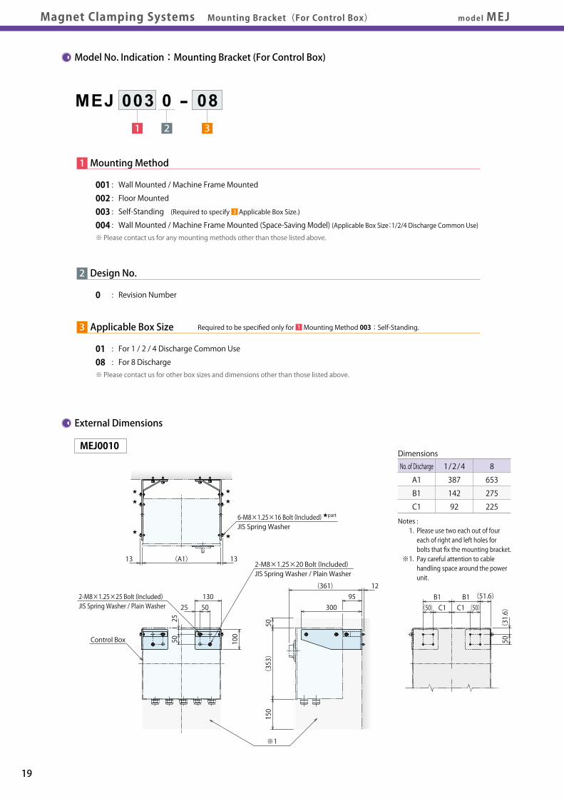
Power UnitMounting Bracket
Magnet Plate
Safety Chain
Cautions
MagnetClamping Systems
Power Unit
model MEJ Model No. IndicationModel No. Indication External DimensionsExternal DimensionsMagnet Clamping Systems Mounting Bracket(For Control Box)
Model No. Indication:Mounting Bracket (For Control Box)
31 2
MEJ 003 0 - 08
19 20
3
3 Applicable Box Size
01 : For 1 / 2 / 4 Discharge Common Use08 : For 8 Discharge※ Please contact us for other box sizes and dimensions other than those listed above.
1 Mounting Method
001 : Wall Mounted / Machine Frame Mounted002 : Floor Mounted003 : Self-Standing (Required to specify Applicable Box Size.)004 : Wall Mounted / Machine Frame Mounted (Space-Saving Model) (Applicable Box Size:1/2/4 Discharge Common Use)※ Please contact us for any mounting methods other than those listed above.
2 Design No.
0 : Revision Number
Notes : 1. Please use two each out of four each of right and left holes for bolts that fix the mounting bracket. ※1. Pay careful attention to cable handling space around the power unit.
External Dimensions
(31.6)
50
(50) C1 C1 (50)
(51.6)B1B1
150
(353)
50
1295
300
(361)
※1
25 50130
5025
100
(A1) 1313
★
★
★
★
★
★
No. of Discharge
A1
B1
C1
1/2/4
387
142
92
8
653
275
225
DimensionsMEJ0010
1Required to be specified only for Mounting Method 003: Self-Standing.
6-M8×1.25×16 Bolt (Included) ★part
JIS Spring Washer
2-M8×1.25×20 Bolt (Included)JIS Spring Washer / Plain Washer
2-M8×1.25×25 Bolt (Included)JIS Spring Washer / Plain Washer
Control Box
Notes : 1. MEJ0040 is only for the box size for 1/2/4 discharge common use. 2. For mounting to the wall / machine frame, use five parts out of nine mounting holes marked with ◆.
(353)
(148.4)
6
30330
(35)(266)
300
13 13(A3)
B3
★
★
★
★
★
★
◆
◆
◆★
★★
★
★
★★
★
★
★
★
★
★
★
★
★
◆
◆
◆
◆
◆
◆
13 13(A2)
C2105 105B2
★
★
★
★
★
★
(353)
(148.4)
300
12
(266)
75100
25
(5)
No. of Discharge
A2
B2
C2
1/2/4
387
394
184
8
653
660
450
Dimensions
No. of Discharge
A3
B3
1/2/4
387
400
8
653
666
Dimensions
MEJ0020
MEJ0040
※ This drawing shows MEJ0030-01.MEJ0030-0□
14.2 (384) 14.2
(400)
413
20105
(350)
52 140 140
175
175
390.2
25.2
(304)
Details of A Part
20
9.5
5.75
A
Control Box
6-M8×1.25×16 Bolt (Included) ★part
JIS Spring Washer
2-M8×1.25×25 Bolt (Included)JIS Spring Washer / Plain Washer
Control Box
6-M8×1.25×16 Bolt (Included) ★part
JIS Spring Washer
2-M8×1.25×25 Bolt (Included)JIS Spring Washer / Plain Washer
Control Box
5-M8×1.25×25 Bolt (Included)JIS Spring Washer / Plain Washer
16-M8×1.25×16 Bolt (Included) ★part
JIS Spring Washer

Power UnitMounting Bracket
Magnet Plate
Safety Chain
Cautions
MagnetClamping Systems
Power Unit
Model No. IndicationModel No. Indication SpecificationsSpecifications Mounting ExamplesMounting Examples External DimensionsExternal Dimensionsmodel MESMagnet Clamping Systems Safety Chain
3 Mounting Method
BC : Chain (Number of Magnet Blocks Installed: 2)
BF : Sling Hook (Number of Magnet Blocks Installed: 1)※ The number of magnet blocks installed represents quantity required for one set of Safety Chain.
1 Chain Diameter
※ Please refer to the specifications and external dimensions.
4 Chain Length
08 : 800mm15 : 1500mm※ The above shows examples for representing chain length. Chain can be set to any length in 100 mm increments. Some errors in the chain length may be observed depending on the number of chains used. Enough chain length should be allowed to facilitate mounting.
2 Design No.
1 : Revision Number
5 Spacer Height
00 : No Spacer05 : 50mm10 : 100mm※ Spacer block height is adjustable in 50 mm increments up to 100 mm at maximum. For spacer block height over 100 mm, please contact us. Spacer block should be used in cases where the top surface of the magnetic plate is lower than that of the mold platen of molding machine (or the magnet plate is smaller than the mold platen). For details of shapes, please contact us.
00:No Spacer
PlatenMagnet Plate
Spacer Height
□□:With Spacer
Spacer
Sling HookChain Chain
BC:Chain BF:Sling Hook
Notes : ※3. When using BF:Sling Hook with two eyebolts on one side, two sets of safety chain are required. 1. The drawings describe different mounting methods on the movable and stationary platen sides in order to show examples for mounting methods. No need to install the system using different mounting methods as shown in these drawings. 2. For magnet block mounting positions on the stationary mold platen side, consideration should be given to an extractor.
21 22
3 4 5
Model No. Indication:Safety Chain
1 2
MES 100 1 - BC - 05 - 00
Specifications
Model No.
Applicable Magnet Plate Model No. ※1
Chain Operating Load (Static Load)/ A Chain ton
Mass of Chain kg/m
Mass of Sling Hook ※2 kg
MES0501
MEG/MEK
0.50
0.55
0.2
MES0601
MEG/MEK
1.10
0.83
0.5
MES0801
MEK
2.00
1.30
0.9
MES1001
MEK
3.20
2.11
1.7
MES0811
MEG
MES1011
MEG
MES1301
MEK
5.20
3.27
3.4
MES1601
MEK
8.00
5.34
6.9
MES2001
MEK
12.50
8.37
11.5
Notes : ※1. Please contact us for the larger sizes for model MEG. ※2. Mass of sling hook shows the mass only of the sling hook block of BF:Sling Hook. 1. Select a sling hook based on the weight of mold half on the movable platen or stationary platen side, whichever is heavier.
Model No. Applicable Magnet Plate Model No. ※1
Block Dimensions
Chain Margin
Chain Dimensions
Eyebolt Size For Mold Side ※5
A B C DA DB E F G H Mounting Bolt ※4
AA AB AC AD AE Min.BA Min.BB Max.BB
MES0601 MEG/MEK 75 32 32 22.5 - 47 15 1 17 2-M12×1.75×50 21 6 17.6 30 200 or more M10×1.5 M16×2 M33×3.5
MES0501 MEG/MEK 70 30 30 20 - 45 17 1 16 2-M12×1.75×50 17 5.35 15 25 200 or more M8×1.25 M10×1.5 M24×3
MES0811 MEG
36
MES1011 MEG
36
MES0801 MEK
45
110 45
37.5 - 65 21 0 18 2-M16×2×70 28 8 24 40 200 or more M12×1.75 M20×2.5 M33×3.5
MES1001 MEK
45
120 65
42.5 - 85 21 0 18 2-M16×2×90 35 10 30 50 200 or more M20×2.5 M24×3 M45×4.5
MES1301 MEK 125 65 45 42.5 - 90.1 29.9 0 18 2-M20×2.5×100 43.5 13 39 65 200 or more M24×3 M30×3.5 M52×5
MES1601 MEK 220 100 45 50 40 125.1 24.9 0 18 4-M20×2.5×130 59.2 16 48 80 200 or more M30×3.5 M36×4 M64×6
MES2001 MEK 290 100 45 45 40 125.1 24.9 0 18 6-M20×2.5×130 74 20 60 100 300 or more M42×4.5 M48×5 M80×6
Notes : ※4. In case a spacer is used, the clamping system comes with mounting bolts provided in consideration of the spacer height. ※5. The eyebolt size indicates the effective range of chain or hook dimensions, not compatibility in terms of strength.
Mounting Examples
For model -BC:Chain For model -BF:Sling Hook
Platen Side
Mounting Bolt
Mold Side
H
G C
FEB
AEChain Margin
AEChain Margin
Mold
PlatenPlaten
1 Set 1 Set
For model -BC:Chain For model -BF:Sling Hook ※3
Chain Dimensions
AA
AB
ADAC
MES0501 / MES0601 / MES08□1MES10□1 / MES1301
MES1601 MES2001
ADBDBDADADBDB
ADBDADADB
ADADA
For Use of One Eyebolt on One Side of the Mold For Use of Two Eyebolts on One Side of the Mold
Magnet Plate
1 Set
Eyebolt Size BA(model -BC:Chain)
Eyebolt Size BB(model -BF:Sling Hook)
※ This drawing below shows Spacer Height:00 (No Spacer).External Dimensions 5

Power UnitMounting Bracket
Magnet Plate
Safety Chain
Cautions
MagnetClamping Systems
Power Unit
model MEK/MEC/MEJ/MESMagnet Clamping Systems Cautions Notes for DesignNotes for Design Maintenance and InspectionInstallation Notes Warranty
Cautions
● Notes for Design
1) Check specifications. ● Please use each product according to the specifications. ● The operating temperatures of magnetic plates (on mold contact surface) are 0 ~ 120℃. Note, however, that if the temperature exceeds specifications the attractive force will drop and will not be restored even if the temperature is returned to the normal range. ※ If that happens, stop production, suspend the mold from a crane and
re-magnetize the clamp after demagnetization.
2) Rated Clamp Force Calculation Method ● The clamp force of the magnet clamp (attractive force of the magnet) is based on the contact area (number of magnet blocks) between the mold mounting plate and the magnet plate. A smaller mold decreases the clamp strength. If the mold mounting plate does not contact all the magnet blocks, calculate the rated clamp force ※1 referring to the following calculation example.
Calculation Example The movable platen with the following magnet plate format is used in the reference. MEG/MEK1201-7S IMM Force 1200kN (≒120 ton) Magnet Block φ70mm / 16 blocks Total Clamp Force 100.32kN (6.27kN per Block)
① Count the number of magnetic blocks contacting the entire surface of the mold mounting plate. ・Entire Block Contact×4 Units ・Approx. 50% Contact×8 Units ・Approx. 25% Contact×4 Units
② Total number of magnetic blocks contacting the mold mounting plate. Total Units=4 Units+8 Units×0.5+4 Units×0.25=9 Units
③ Multiply the clamp force of each magnet block (6.27kN / unit) by the total number of units. Rated clamp force ※1=6.27kN / unit×9 units=56.43kN ※1. The above calculation is for ideal conditions between the magnet plate and the mold.
1. If there are holes or notches on the rear surface of the mold mounting
plate, subtract the area from the contact area (no. of magnet blocks)
with the mold mounting plate.
2. Actual clamp force may be reduced due to the conditions of the mold
mounting plate.
3) Factors regarding Reduced Clamp Strength ● Influence of the material of the mold mounting plate Actual clamp force may degrade below the rated clamp force due to the material of the mold mounting plate.
If the material of the mold mounting plate is S55C, S45C, or SUJ, etc., the mold may be difficult to release when the clamp is turned OFF. This is due to residual magnetism. Magnetic strength decreases with increasing gap between the mold mounting plate and magnetic plate. Take caution regarding this issue during use.
● Influence of the roughness of the mold mounting plate The roughness of the mold mounting plate decreases force, as indicated in the following table. Confirm the roughness of the mounting plate.
● Influence of the Temperature The clamp strength decreases according to the temperature of the mold.
Material SS400 S55C / S45C SCM440 / SNCM240 SUJ2 / SUS405 FC250
Clamp Force 100 % (Standard) 90 ~ 100% 78 ~ 93% 75 ~ 90% 54 ~ 64%
Roughness ▽▽▽ (Rz1.6 ~ 3.8) ▽▽ (Rz7.5 ~ 15.5) ▽ (Rz85 ~ 150)
Clamp Force 100% about100% about 90%
Magnet Block
Magnetic PlateMEG/MEK1201-7S
Mold Mounting Plate
100
90
80
70
0Decreasing Rate of Attractive Force (%)
Magnet Plate Surface Temperature(℃)
0 60 120 180
● Influence of the Air Gap Between the Magnet Plate and the Mold Mounting Plate Do not use a warped mold mounting plate or a deformed mold. Magnetize the equipment after ensuring there is no air gap between the magnet and mounting plates. If an air gap forms between the magnet and mold mounting plates due to a warped or damaged mold mounting plate or presence of a foreign substance, the clamp force decreases as in the following diagram.
4) Concerning the IMM
① An error in the ejector force setting may cause the mold to accidentally drop.
● When the ejector force (ejection force and speed) exceeds the clamp force, the mold is pushed by the ejector pin and falls.
● Check for errors in ejector pin length or misalignments in the location of the holes.
● Use a crane to suspend the mold to remove and insert ejector pins.
② When the mold opening force exceeds the clamp force, the mold drops.
● Ensure that the mold opening force does not exceed the clamp force. It is recommended that measures to prevent the mold from falling should be taken to prepare for an accident, in the event of an abnormal mold opening force.
③ When an overweight mold, exceeding the clamp force, is used, the mold will drop.
④ Use a clamp force that exceeds twice the nozzle touch force.
Setting Target : Ejection Force ・・・ Less than 1/3 of the movable platen clamp strength Speed ・・・ Less than 50mm/sec
100
90
80
70
0Decreasing Rate of Attractive Force (%)
Air Gap Between Plates (mm)
0 0.1 0.2
23 24

Power UnitMounting Bracket
Magnet Plate
Safety Chain
Cautions
MagnetClamping Systems
Power Unit
Notes for Design Maintenance and InspectionMaintenance and InspectionInstallation NotesInstallation Notes WarrantyWarrantymodel MEK/MEC/MEJ/MESMagnet Clamping Systems Cautions
Cautions
● Installation Notes
1) Do not touch the button or key switches with wet hands. This may result in electrocution.
2) As the magnet plate generates a strong magnetic field, ensure that people with heart pacemakers do not approach this device. If the pacemaker malfunctions due to the effect of the magnetic field, this may be dangerous for the body.
3) Do not approach the contact surface with magnetic items, i.e. iron, while the equipment is locked. As the strength of the magnet is extremely strong, magnetic objects will attach to the clamp surface. Injuries may result from fingers or hands getting caught between objects and the plate.
4) When the mold is open, do not place any body parts, i.e. hands and feet, etc., in the machine.
5) As the magnetic field lines rise above the front surface (mold side) of the mold mounting plate by about 20mm, do not approach the magnet plate with items easily affected by magnetic fields, i.e. cell phones, magnetic cards, compact disks, etc., to avoid malfunction or damage to the items.
6) Even when the clamp is turned OFF (demagnetized), caution is required as a small residual amount of magnetism is still generated.
7) Do not use a warped mold mounting plate or a deformed mold. The clamp capacity decreases with space between the magnet plate and mold mounting plate.
8) Ensure that the contact surfaces of the magnet and mold mounting plates are always clean. Although water and oil on the contact surface do not directly cause the clamp capacity to decrease, dust and foreign substances adhere to these liquids and may cause gaps to form between the magnetic and the mold mounting plates.
9) The clamp force changes according to the contact area between the mold mounting and magnet plates. In addition, the clamp capacity may decrease according to the conditions of the mold mounting plate. Always perform an initial test for each mold to confirm the conditions to be appropriate.
10) When using ejector pins, always check to ensure the proper pin length and hole alignment. The mold may be pushed off the magnetic plate by the ejector pin and may fall.
11) The temperature of the contact surfaces of the mold mounting and magnetic plates should be within 0 ~ 120 ℃. 12) Always visually confirm safe mold handling when using the push button or key switches of the control panel to avoid operating errors.
13) When disconnecting power to the molding machine, also disconnect power to this equipment.
14) This equipment does not operate properly with an unstable power supply. Errors may occur when the power supply is momentarily interrupted or during lightning strikes. Do not operate the device when abnormal power fluctuations are anticipated, i.e. lightning strikes.
15) Remove the key switch of the control panel and store in a safe location except when switching molds.
16) Do not operate the device when the voltage exceeds the range of the primary power source. (±10%)
17) Ensure that the control panel and power unit remains free from water or oil. In the event that water or oil is spilled onto this equipment, stop all operations.
18) Precautions for Use of Auxiliary Mold Brackets
① The chain operating load represents static load. Do not reuse the chain if any impact load is applied to it.
② Use the chain with minimum chain slack. This can minimize chain shift length even in the worst case.
③ For eyebolt used on the mold side, take into account the mounting position.
Take into account a balance in the horizontal direction.
Take into account a balance in the front-back direction.
Mold
Mold
The eyebolt is not mounted in the positionof the center of gravity.The mold sways very much from side to side.
The eyebolt is mounted too farfrom the mold mounting surface.
Two eyebolts are mounted.The mold sways just a little from side to side.
The eyebolt is mounted closeto the mold mounting surface.
The eyebolt is mounted in the position of the center of gravity. The mold sways just a little from side to side.
Tie-Bar
● Maintenance and Inspection ● Warranty
1) Disconnect the power to the molding machine and the magnet clamp before starting maintenance work. Ignoring these instructions may lead to accidental death by electrocution.
2) Do not operate the equipment with wet hands.
3) As the magnet plate generates a strong magnetic field, ensure that people with heart pacemakers or other devices do not approach this device.
4) Do not approach the contact surface with magnetic items, i.e. iron while the equipment is locked. As the strength of the magnet is extremely strong, magnetic objects attach to the clamp surface. Injuries may result from fingers or hands getting caught between objects and the plate.
5) This equipment should only be handled by personnel authorized by the Safety Management Manager.
6) Ensure that a third party does not mistakenly operate the equipment during maintenance and inspection.
7) Always visually confirm safe mold handling when using the push button or key switches of the control panel to avoid operating errors.
8) Always display appropriate signs or placards while maintaining or inspecting equipment.
9) Confirm the following points before turning the power ON after conducting maintenance / inspection. ① All tools and jigs used during maintenance / inspection have been removed. ② Removed covers and cables have been returned to their original locations.
10) Ensure that the control panel and power unit remains free from water or oil. In the event that water or oil is spilled onto the machinery, stop all operations.
11) As the magnetic field lines extend from the front surface (mold side) of the mold mounting plate by about 20mm, do not approach the magnet plate with items easily affected by magnetic fields, i.e. cell phones, magnetic cards, compact disks, etc., to avoid malfunction or damage to the items.
12) The power unit and the magnet plate have high voltage terminals. They are extremely dangerous. Do not touch the terminals unless performing authorized maintenance. Touching these terminals may lead to accidental death by electrocution.
13) If the equipment is taken apart or modified the warranty will be void, even within the warranty period.
1) Warranty Period
● The product warranty period is 18 months from shipment from our factory or 12 months from initial use, whichever is earlier.
2) Warranty Scope
● If the product is damaged or malfunctions during the warranty
period due to faulty design, materials or workmanship, we will
replace or repair the defective part at our expense.
Defects or failures caused by the following are not covered.
① If the stipulated maintenance and inspection are not carried out.
② If the product is used while it is not suitable for use based on
the operator’ s judgment, resulting in defect.
③ If it is used or handled in inappropriate way by the operator.
(Including damage caused by the misconduct of the third
party.)
④ If the defect is caused by reasons other than our responsibility.
⑤ If repair or modifications are carried out by anyone other than
Kosmek, or without our approval and confirmation, it will void
warranty.
⑥ Other caused by natural disasters or calamities not attributable
to our company.
⑦ Parts or replacement expenses due to parts consumption and
deterioration.
(Such as rubber, plastic, seal material and some electric
components.)
Damages excluding from direct result of a product defect shall
be excluded from the warranty.
25 26

For quick ejector rod details, please contact your KOSMEK representative,
visit the KOSMEK website at [http://www.kosmek.com], or refer to the quick ejector rod catalog.
Exchange start Two seconds progress Four seconds progress Completed in about five seconds ※1
※1. The changing time varies with molding machine size, ejector rod length, work environment, or else.
The ejector rod has been divided into
a base rod and an attachment rod for
speed, simplicity and ease-of-use when
changing ejector patterns.
No tools are required, allowing changes
in mere seconds.
Move the ejector plate
fully forward.
model PME
Pull out the attachment
rods by hand.
Arrange them in the new
pattern.
Ejector rod patternchange
in seconds !
Changing Ejector Rods
Quick Ejector Rod
Magnet Clamping SystemsNew
The World's Thinnest (37mm) Magnet Clamp!! (model MEG)Magnet clamping systems that ensure safety in operations.Large reduction in mold changing time.
CAT.NO.MEK002-04-GBPrinted in Japan
2013. 03 First 1Ry2017. 06 4th 1Ry
http://www.kosmek.com
JQA-QMA10823KOSMEK HEAD OFFICE
● FOR FURTHER INFORMATION ON UNLISTED SPECIFICATIONS AND SIZES, PLEASE CALL US.
● SPECIFICATIONS IN THIS LEAFLET ARE SUBJECT TO CHANGE WITHOUT NOTICE.
KOSMEK (U.S.A.) LTD.650 Springer Drive, Lombard, IL 60148 USATEL. +1-630-620-7650 FAX. +1-630-620-9015
KOSMEK LTD - INDIAF 203, Level-2, First Floor, Prestige Center Point, Cunningham Road, Bangalore -560052 IndiaTEL.+91-988056169567 Soi 58, RAMA 9 Rd., Suanluang, Suanluang, Bangkok 10250TEL. +66-2-300-5132 FAX. +66-2-300-5133
1-5, 2-Chome, Murotani, Nishi-ku, Kobe 651-2241TEL.+81-78-991-5162 FAX.+81-78-991-8787
HEAD OFFICE
BRANCH OFFICE (U.S.A.)
KOSMEK USA Mexico OfficeBlvd Jurica la Campana 1040, B Colonia Punta Juriquilla Queretaro,QRO 76230 MexicoTEL.+52-442-161-2347
MEXICO REPRESENTATIVE OFFICE
BRANCH OFFICE (INDIA)
THAILAND REPRESENTATIVE OFFICE
KOSMEK EUROPE GmbHSchleppeplatz 2 9020 Klagenfurt am Wörthersee AustriaTEL.+43-463-287587 FAX.+43-463-287587-20
BRANCH OFFICE (EUROPE)
Related Documents