UNCLASSIFIED AD NUMBER AD823185 NEW LIMITATION CHANGE TO Approved for public release, distribution unlimited FROM Distribution authorized to U.S. Gov't. agencies and their contractors; . Administrative/Operational Use; Oct 1967. Other requests shall be referred to Army Missile Command, ATTN: AMSMI-RS, Redstone Arsenal, AL 35809. AUTHORITY Army Missile Command ltr dtd 18 Jun 1970 THIS PAGE IS UNCLASSIFIED

Welcome message from author
This document is posted to help you gain knowledge. Please leave a comment to let me know what you think about it! Share it to your friends and learn new things together.
Transcript

UNCLASSIFIED
AD NUMBER
AD823185
NEW LIMITATION CHANGE
TOApproved for public release, distributionunlimited
FROMDistribution authorized to U.S. Gov't.agencies and their contractors; .Administrative/Operational Use; Oct 1967.Other requests shall be referred to ArmyMissile Command, ATTN: AMSMI-RS, RedstoneArsenal, AL 35809.
AUTHORITY
Army Missile Command ltr dtd 18 Jun 1970
THIS PAGE IS UNCLASSIFIED

REPORT NO. RS-TR.67-11
mlI I°PRACTICAL GALVANIC SERIES
I :by
"Charles M. FormanE, A. Verchot
October 1967
DISTRIBUTION LIMITEDSEE NOTICES PAGE
F;; edietone, Araenal I, Alaban rv
DEC EI5 1967
Opm AMSMI-1021. I DEC 65 PREVIOUS LOITHORf IS OBSOLETE

DISPOSITION INSTRUCTIONS
Destroy this report when no longer needed.Do n'it return it to the originator.
DISTRIBUTION LIMITATION
This dszument is subject to special export controls and eachtransmittal to foreign governments or foreign nationals maybe made only with prior approval of this Command, ATTN:AMSMI-RS.
DISCLAIMER
The findings in this report are not to beconstrued as an official Department ofthe Army position unless so designatedby other authorized documents.

10 October 1967 Report No. RS-TR-67-11
PRACTICAL GALVANIC SERIES
by
Charles M. FormanE. A. Verchot
DA Project No. 1C024401A328AMC Management Structure Code No. 5025-11.294
STATFNENT #2 UNCLASSIFIED
Tbt* 4ocument is subject to special export controls and each
tr•nswlttal to foreign government- or foreign nationals may beM A 0417 Wit hi prior appro v l ol'.
Materials Engineering and Development BranchStructures and Materials Laboratory
Research and Development DirectorateU, S Army Missile Command
Redstone Arsenal, Alabama 35809
I,.~.-.~ - - - . . . - -. ~ . . - - -

ABSTRACT
The prime objective of this work was the development of a practicalgalvanic series of mctals and alloys to aid in the sclecti-n of compatible mate-rials for missile systems. This was accomplished bý studying the variousmetals and alloys coupled with a 110 copper alloy standard as the referenceelectrode, and monitoring potentials with a self-balancing potentlometric-typerecorder. Each couple was partially immersed in a 5-percent salt (sodiumchloride) solution.
The effects of coatings and platings on the galvanic relationships existingbetween metals and alloys were also studied. Coatings and platings were studiedwith aluminum, magnesium, and steel as the substrates.
Other studies included the effects on galvanic activity when strengthlevels within the same alloy were varied, carrent versus weight-loss measure-ments, and the comparison of other conducting solutions with the 5-percentsodium chloride solution used in the generation of this series.
The study of the effect ef strength level on galvanic activity showed thatgalvanic potentials can exist between specimens of the same alloy at differentstrength levels, Also, the galvanic potential varies with different conductingso:utions.
ACKNOWLEDGEMENT
The authors wish to express their gratitude for the helpful suggestionsand encouragement offered by Dr. 11. I. Uhlig, Professor of Metallurgy,Massachusetts Institute of Technology, and Dr. J. A. MeLaren of the ArmyMissile Command at Redstone Arsenal, Alabama.
iij

FOREWORD
The work described in this report was performed as a part of the subtask"Corrosion Protection Coatings" under DA Project No. 1C024401A:128, AMCManagement Structure Code No. 5025.11.294, Metals Research for ArmyMaterial. The purpose of the program was the generation of a practical galvanicseries of metals and alloys to aid in the seclection of compatible materials formissile systems.
iii

CONTENTS
Page
Section I. INTRODUCTION ............................ 1
Section II. DISCUSSION . ............................... 2
Section Ill. METIHODS AND 1I1?OCEDUIBES ................... 19
1. Coatings Used on Mlagnesium ....................... 19
2. Coatings Used on Alumitumm ........................ 203. Electroplated Coatings on Steel ..................... 21
Section IV. IRESULTS ................................. 23
1. Coated Magnesium .............................. 232. Coated Aluminum ....................................... 233. Electreplated Steel ...................................... 254. Effects of Varying Degrees of Strength Level
on the Galvanic Properties of the Same Alloy ................. 255. Current Versus Weight-Loss Measurements ................. 306. Effect of Conducting Solutions on Galvanic
Relationships of Metals as Compared withFive-Percent Sodiam Chloride Solution ...................... 30
Section V. FIJTIJII{ PLANS ........... . 932
Section VI. CONCLUSIONS ........ ............................. 33
SELECTED BIBLIOGRAPHY ..................................... 34
ILLUSTRATIONS
Table Page
I List of Metals and Alloys on Which Galvanic ..
II Practical Galvanic Series ..................... 121
III Operating Conditions for Electroplated Coatingson Steel ...... ..................................... 22
IV Effects of Various Coatings on the GalvaidcActivity of Aluminum ................................... 24
v

1
iLLUSTRATIONS (Concluded)
Table Page
V Galvanic Potential Measurements on Electroplated
Specimens ............................................. 26
VI Effect of Strength Level on Galvanic Activity ofSeveral Aluminum Alloys, ....... .......................... 27
VII Effect of Strength Level on Galvanic Activity of300 Series Stainless Steels ................................ 28
VIII Effect of Strength Level on Galvanic Activity of300 Series Stainless Steels ................................ 28
IX Effect of Strength Level on Galvanic Activity of300 Series Stainless Steels ....... ......................... 29
X Effect of Strength Level on Galvanic Activity of300 Series Stainless Steels ................................ 29
XI Effect of Strength Level on the Galvanic Activityof 13 V- 11 Cr-3 Al and 6 AI-4 V Titanium Alloys ............ 30
XII Current-Weight Loss Measurements ........................ 31XIII Effect of Several Conducting Solutions on Galvanic
Relationships of Several Metals Compared withFive-Percent Sodium Chloride Solution ..................... .31
Figure Page
I Recorder ......... .................................... 42 Galvanic Cell (Tnoluding Crln, q 1 "ehptkI ' Ellovtrode.. 43 Water Bath, Galvanic Cell, Calomel Reference, and
Therm ometer ........................................ 54 Overall Setup ........................................... 55 Treated Magnesium, Aluminum, and Steel Samples ........... 66 Metals and Alloys, Treated and Untreated, Included
in Series ......... ..................................... 67 Typical Electrode ........ ............................... 7
vi

Section I INTRODUCTION
Designers of missile components are faced with a dilemma in selectingmetals and alloys that arc compatible. The term "compatible materials" refersto metals that will exhibit the least amount of galvanic activity when they arcconnected in a corrosive environment. A guide or reference is needed whenchoosing materials.
Existing "galvanic" series are generally too theoretical for practicaluse. They are u3uallv obtained by measuring the potential generated between astandard hydrogen electrode and the pure metal immersed in a solution of themetal's ions, rather than by measurement of the myriad of alloys actuallyencountered. Also, many of these series list and treat groups of alloys as ifthey were completely compatible. For example, all aluminum alloys may beconsidered compatible by such a series. Hlowever, it becomes evident from astudy of the galvanic relationships existing between metals and alloys that allalloys within a group, e. g. , aluminum or stainless steel, are not compatible.Also, potential differences exist between samples of the same alloy at differentstrength levels.
To combat these difficulties, a galvanic series has been generated bydirect measurement of the metals and alloys used in missile systems, to enablethe selection of compatible materials for missile uses.
S•1

Section II. DISCUSSION
When two metals are connected in a corrosive environment, the anode(negative electrode in a discharging battery in this case) will begin to corrode.The amount of corrosion depends upon the resulting current density (currentper unit area). However, since current and voltage are related in Ohm's law(I = E/R), the voltage or potential difference developed between the two elec-trodes shows the tendency of the anode to corrode.
Ohm's law, which states that current is equal to the voltage divided bythe resistance, is the basis for the premise that the galvanic series may beused for the selection of compatible materials. The series is used by pickingcandidate materials with the least potential differences.
In this study, practical conditions were used for measurements, ratherthan ideal or standard. The basic setup consisted of a potentiometric-typerecorder connected in series to the electrodes in the galvanic cell. This poten-tiometer permitted potential measurements with essentially no power withdrawnfrom the system being measured.
The galvanic cell was composed of two 1 1/8 x 4 x 0. 065-in. electrodespartially immersed in a 5-percent salt (sodium chloride) solution. One of theelectrodes was the standard reference electrode, copper 110 alloy, and the otherwas the metal or alloy being tested. The exposed surface area of each electrodewas 2 in. 2. A calomel half-cell was used intermittently to verify the results,thereby insuring that the galvanic response of the copper 110 reference electroderemained constant. The calomel was partially immersed in a separate containercontaining 1. 0 N potassium chloride solution, and was connected to the 5-percentsalt solution by a salt bridge also containing 1. 0 N potassium chloride.
The series was compiled using open-circuit potential values, i. e. , withessentially no current flowing through the cell. Copper 110, the referencematerial, was assigned the value of 0. 00 V, and all other alloys were placed inthe series according to their relationship to this standard. The series wasarranged from the most anodic to the most cathodic (from the least noble to themost noble).
Passivation of stainless steel alloys was effected by immersion for30 min in a 20-percent nitric acid solution held at 50°C.
The galvanic cell, and calomel electrode when used, were placed in aconstant temperature water bath, and the temperature was held constant at 25 0 C.The apparatus used is shown in Figures 1 through 4.
2

The metals and alloys used in the series, untreated and treated, arelisted in Table I. The galvanic series is presented in Table II. Figures 5through 7 show collections of test specimens of the many metals and alloys,treated and untreated, that make up the galvanic series. Figure 5 indicates thecoated magnesium and aluminum samples, and the electroplated steel samples.Figure 6 shows both the treated and untreated samples. An electrode of thetype used in making the galvanic measurements is shown in Figure 7.
3

FIGUR~E], RECORDER
FIGURE 2. GALVANIC CELL (INCLUDING CALOMEL"CHECK' ELECTRODE)
4

I
FIGURE 3. WATER BATH, GALVANIC CELL, CALOMELREFERENCE, AND THERMOMETER
FIGURE 4. OVERALL SETUP

TV'
FIGURE 5. TREATED MAGNESIUM, ALUMINUM,AND STEEL SAMPLES
~ ~ ~ ~s . . .. ' - • _ _
- I I
4w m Ie ONab I"II I
I"Ii i-
41,1i. -U- aL* W -f
FIGURE 6, METALS AND ALLOYS, TREATED AND UNTREATED,INCLUDED IN SERIES
6

FIGURE 7. TYPICAL ELECTRODE
7

TABLE I. LIST OF METALS AND ALLOYS ON WHICHGALVANIC MEASUREMENTS WERE MADE
Magnesium Alloys
AZ 31 B
AZ 91 B
Zinc Alloys
AG40A zinc-base alloy die casting
M & H Zinc Company zinc:
Pb: 0.05-0.07
Cd: 0.005 maxFe: 0.010 maxCu: 0.95-1.05%
Mg: 0.010-0.012%
Titanium Alloys
75 A( Heat treatment not known, probably
6 A1-4 V annealed. Rockwell C hardness, 36.(2 Heat treated: 1700'F for 15 min,
water quenched, 950'F for 4 hr.Rockwell C hardness, 41.5
5 Al-2.5 Sn
8 Mn/1 Annealed: 1450^ F for 30 min, air
13 V-11 Cr-3 Al cooled. Rockwell C hardness, 33.52 Heat treated: 1450'F for 30 min,
water quenched, 900'F for 24 hr.Rockwell C hardness, 45.5

I U
TABLE I. LIST OF METALS AND ALLOYS ON WHICHGALVANIC MEASUREMENTS WERE MADE(Continued)
Aluminum-Base AlloyDie Castings Alkminum Alloys Wrought
Alloy 13 or 512A 2014 (T6 + 0)
"Alloy A360 or SG100A 2024 (T4 + 0)Alloy A380 or SC84A ( bareAlloy 218 or G8A 7075 T6 \, nd + 0)
alcladCopper Alloys 1100 (H14 + 0)
Copper 110 5083 H34
Bronze 220 5456 (H343 + 0)
Low bronze 240 3003 H25
Muntz metal 280 5052 (H12 + 0)
Naval brass 464 4043 H14
Phosphor bronze (B-i) 534 6061 (TO + 0)
Ambraloy 612 1160 H14
Everdur 655 5056 t114
Cupro nickel (30%) 7151 6151 T6
Nickel silver (16%) 770 7079 T6
Yellow brass 2(68 7071 TG
2014 T3
Steels
Stainless: Type 430 (A & P)*Type 304 (A & P)
In active state: annealed,Type 347 (A & P) 1/4, '/2, and full hard."Only annealed in passive
state17-7 PH (A & P)
Carp 20cb (A & P)Type 316 (A) Annealed, /4, /., and full
hardType 410 (A)
' (A) - active state(P) passive state
9

TABLE I. LIST OF METALS AND ALLOYS ON WHICHGALVANIC MEASUREMENTS WERE MADE(Continued)
Steels (Continued)
Stainless: n active state: annealed,Type 321 (A & P /4, '/2, and full hard.
"" -Only annealed in passive
stateTp 0 Bright (A & P)Type 202ul (A & P)"Type 350 (A & P)AM 355 (A & P)Type 301 (A & P)Type 305L (A & P)
Type 309 (A)Type 316L (A & P)Type 201 (A & P)Type 286 (A & P)Type 310 (A & P)
Other: AISI 1010Al-Si coated steel (Ti)Al (pure) coated steel (T2)
Other Metals and Alloys
MolybdenumTungsten
Columbium (niobium)TantalumColumbium - 1% zirconium90-10 Tantalum-tungstenCadmiumLead
NickelMonel
Uranium, depleted (unalloyed)Uranium, depleted (8% Mo)GraphiteTinBerylliumIndium
j 10

TABLE I. LIST OF METALS AND ALLOYS ON WHICHGALVANIC MEASUREMENTS WERE MADE(Concluded)
Coated Aluminum Alloys Coated Magnesium Alloys
Alloys used: Alloys used:
1. 1100 H14 1. AZ 31 B2. 2014 T6 2. AZ 91 B3. 3003 H254. 5052 H12 Coatings applied:5. 6061 T6 1. Chrome pickle (Dow 1)6. 7075 T6 2. Sealed chrome pickle (Dow 10)
3. Dichromate (Dow 7)Coatings applied: 4. Galvanic anodize (Dow 9)
1. Sulfuric acid anodize 5. Dilute chromic acid (Dow 19)2. Chromic acid anodize a. 60-65 V
6. Dow 173. Conversion coating 1 (Alrok) b. 90 V4. Conversion coating 2 7. HAE a. 60-65 V5. Conversion coating 3 b. 85 V
Electroplated Coatings on Steel
Brass on AISI 1010 steelCadmium (brush plated) on AISI 1010 steelCadmium (brush plated) on 202 stainless steelCadmium on AISI 1010 steelCadmium (brush plated) on 321 stainless steelChromium on nickel on copper on AISI 1010 steelChromium on nickel on AISI 1010 steelChromium on 202 stainless steelChromium on AISI 1010 steelChromium on 410 stainless steelChromium on electroless nickel on AISI 1010 steelChromium on 430 stainless steelElectroless nickel on AISI 1010 steelNickel on copper on AISI 1010 steelNickel on AISI 1010 steelTin on AISI 1010 steelZinc on AISI 1010 steel
•,. 11

TABLE II. PRACTICAL GALVANIC SERIES
(Open Circuit Potential Values - Compared to Copper 110 Alloy Reference)
Alloy Treatment Voltage
AZ 91B Magnesium HAE coating applied at 60-65 V -1.480AZ 31B Magnesium Chrome pickle treatment -1.357AZ 91B Magnesium Chrome pickle treatment -1.350AZ 31B Magnesium Dow 19 treatment -1. 345AZ 31B Magnesium Untreated -1.344AZ 31B Magnesium HAE coating applied at 60-65 V -1.332AZ 31B Magnesium Galvanic anodize treatment -1.330AZ 31B Magnesium Dichromate treatment -1. 330AZ 91B Magnesium Dichromate treatment -1.323AZ 91B Magnesium Untreated -1.314AZ 91B Magnesium Dow 19 treatment -1.313AZ 91B Magnesium Sealed chrome pickle treatment -1.310AZ 31B Magnesium Sealed chrome pickle treatment -1.305AZ 91B Magnesium Galvanic ,inodize treatment -1.300AZ 31B Magnesium Dow 17 coating applied at
60-65 V -1.294AZ 31B Magnesium HAE coating applied at 85 V -1. 284AZ 91B Magnesium Dow 17 coating applied at
60-65 V -1. 261AZ 31B Magnesium Dow 17 coating applied at 90 V -1.257AZ 91B Magnesium Dow 17 coating applied at 90 V -1. 234AZ 91B Magnesium HAE coating applied at 85 V -1.226Zinc on AISI 1010
steel -0. 793Zinc (AG40A) -0. 786Zinc (M & 1I Zinc
Company) -0. 784Beryllium -0. 7806061 T6 Aluminum Alrok treatment -0. 7527075 T6 Aluminum Alclad -0.6452014 T3 Aluminum -0. 6391160 H14 Aluminum -0. 6097075 0 Aluminum -0. 6043003 H25 Aluminum Conversion coating 2 -0. 5967079 Aluminum -0.5846061 T6 Aluminum Conversion coating 2 -0. 5805052 H12 Aluminum Conversion coating 2 -0. 571
12

i_IAABLE 11. PRACTICAL GALVANIC 6ERIE6 (Continued)
ALloy Treatment Voltage
Cadmium (brush
plated) on AISI 1010
steel -0. 557
Uranium (depleted)
unalloyed -0. 556Cadmium (brush
plated) on 202stainless steel -0.554
Die-cast 218
Aluminum -0. 549
1100 H114 Aluminum Alrok treatment -0. 546
5052 H12 Aluminum -0. 545
Type 1I (Aluminum
coated stainlesssteel) -0. 541
5052 0 Aluminum -0.534Cadmium on AISI
1010 steel -0.534
Cadmium (brush
plated) on 321stainless 5teel -0. 532
7075 T6 Aluniinund- Conversion coating 2 -0.524
5052 1112 Aluminum Sulfuric anodi re treatment -0.524
5083 Aluminum -0. 5241100 1114 Aluminum Conversion coating 2 -0.5206151 T6 Aluminum -0. 520
5052 1112 Aluminum Alrok treatment -0. 519
5052 H12 Aluminum Chromic anodize treatment -0.514
5456 0 Aluminum -0. 514
1100 H114 Aluminum Chromic anodize treatment -0.5145456 11243 Aluminum -0. 507
4043 H14 Aluminum -0. 507
Type I (Aluminum-
silicon coatedstainless steel) -0. 504
7075 T6 Aluminum Alrok treatment -0.504
5052 1112 Aluminum Conversion coating 3 -0.504
3003 H25 Aluminum Sulfuric anodize treatment -0.504
5052 1132 Aluminum -0. 502
13

TABLE II. PRACTICAL GALVANIC SERIES (Continued) IAlloy Treatment Voltage
1100 0 Aluminum -0.4993003 1125 Aluminum -0.496
3003 H25 Aluminum Chromic anodize treatment -0.494
1100 H14 Aluminum Sulfuric anodize treatment -0.4946061 T6 Aluminum -0.4933003 H25 Aluminum Alruk treatment -0.492
3003 H25 Aluminum Conversion coating 3 -0. 4861100 H14 Aluminum Conversion coating 3 -0.484
7075 T6 Aluminum Chromic anodize treatment -0.4846061 T6 Aluminum Chromic anodize treatment -0.484
7071 T6 Aluminum -0.4846061 T6 Aluminum Sulfuric anodize treatment -0.480
Die-cast A360Aluminum -0.479
Die-cast 13
Aluminum -0.4776061 T6 Aluminum Conversion coating 3 -0.476
7075 T6 Aluminum Sulfuric anodize treatment -0. 4722024 0 Aluminum -0.4727075 T6 Aluminum
(Bare) -0. 4702014 T6 Aluminum Chromic anodize treatment -0.4641100 1114 Aluminum -0. 464
2014 T6 Aluminum Conversion coating 2 -0.4622014 T6 Aluminum Sulfuric anodize treatment -0.460
2014 T6 Aluminum Alrok treatment -0.4592014 T6 Aluminum Conversion coating 3 -0.4566061 0 Aluminum -0.454
2014 T6 Aluminum -0. 4527075 T6 Aluminum Conversion coating 3 -0.448
Indium -0.448
Die-cast A380
Aluminum -0.4442014 0 Aluminum -0.444
2024 T4 Aluminum -0.370
5056 1116 Aluminum -0.369Tin on AISI 1010 3
steel -0.333430 Active stainless
steel -0. 324
14
.. .. .- -----

TABLE II. PRACTICAL GALVANIC SERIES (Continued)
Alloy Treatment Voltage
-0.316Lead
Chromium on nickel on
copper on AISI 1010
steel -0.297
AISI 1010 steel -0. 281
TinChromium on nickel
on AISI 1010 steel -0.250
410 Active stainless -0.230
steelChromium on 202
stainless steel -0.209
Copper on AISI 1010steel-0.203steel
Chromium on 410stainless steel -0. 194
Nickel on copper on
AISI 1010 steel -0. 192
C1lomium on electro-
less nickel on AISI4. -0. 1781:010 steel
Chromium on 430stainless steel -0. 169
Tantalum " -1
350 Active stainlesssel-0. 149steel
Electroless nickel on -
AISI 1010 steel " .- -0. 138
90-10 Tantalum-tungsten
-0.124
310 Active stainlesssteel -0.124
301 Active stainlesssteel
-0. 120
305L Active stainlesssteel -0.113
304 Active stainless: steel -0. 106
430 Passive stainlesssteel -0.094
15

TABLE II. PRACTICAL GALVANIC SERIES (Continued)
Alloy Treatment Voltage
17-7 PH Active stain-
less steel -0. 076
Tungsten -0. 047
Niobium - 1%
zirconium -0. 044
Yellow brass 268 -0. 043
Uranium (depleted)
8% molybdenum -0. 041
Naval brass 464 -0. 041
Muntz metal 280 -0. 034
Brass on AISI 1010steel -0. 032
Nickel silver 18% 770 -0. 022
Ambraloy 612 -0. 019
Low brass 240 -0. 016
316L Active stainlesssteel -0. 013
Bronze 220 -0. 012
Everdur 655 -0.007
Copper 110 (Reference electrode) U.000oo
W00
347 Active stainlesssteel +0. 006
Molybdenum +0. 006
Cupro nickel (30%)7151 +0.012
202 Active (dull)stainless steel +0. 014
Niobium +0. 018
Phosphor bronze
(B-i) 534 +0.034
202 Active (bright)stainless steel +0. 051
Monel +0. 051
347 Passive stainless
steel +0.058
Nickel +0. 064
201 Active stainless
steel +0. 070
16

TABLE II. PRACTICAL GALVANIC SERIES (Continued)
Alloy Treatment Voltage
Carp 20 CB Activestainless steel +0. 074
321 Active stainlesssteel +0. 077
316 Active stainlesssteel +0. 082
Nickel on AISI 1010steel +0. 086
304 Passive stainlesssteel +0. 098
17-7 PH Passive stain-less steel +0.098
305L Passive stainlesssteel +0.100
309 Active stainlesssteel +0, 108
310 Passive stainlesssteel +0.109
301 Passive stainlesssteel +0. 112
321 Passive stainlesssteel +0.116
201 Passive stainlesssteel +0.129
286 Active stainlesssteel +0. 156
316L Passive stainlesssteel +0.156
202 Passive (dull)stainless steel +0. 159
AM 355 Active stainlesssteel +0.167
202 Passive (bright)stainless steel -10. 183
Carp 20 CB Passivestainless steel +0.186
AM 355 Passive stainlesssteel +0. 204
286 Passive stainlesssteel +0.311
17

UTABLE II. PRACTICAL GALVANIC SERIES (Concluded)
Alloy Treatment Voltage
5 Al-2. 5 Sn Titanium +0.42313 V-11 Cr-3 Al Annealed, Rockwell C hardness,
Titanium 33.5 +0.4366 A1-4 V Titanium Heat treatment: 1700'F for
15 min, water quenched, 950'Ffor 4 hr. Rockwell C hardness,41.5 +0.455
Graphite +0.473
6 AI-4 V Titanium Annealed, Rockwell C hardness,36 +0.481
8 Mn Titanium +0.49313 V-11 Cr-3 Al Heat treatment: 14500F for
Titanium 30 min, water quenched, 900'Ffor 24 hr. Rockwell C hardness45.5 +0.498
75 A Titanium +0. 506350 Passive stainless
s teel +0.666
k18(

UFA
Section II., METHODS AND PROCEDURES
The following methods and procedures were used in applying the variouscoatings, both chemical and electrochemical, to magnesium, aluminum, andsteel.
1. Coatings Used on Magnesium
"The magnesium samples were cleaned by immersing in dilute nitricacid and rinsing with water. The solutions used for these metal treatmentswere compounded as described in various references, e. g., the Metal FinishingGuidebook Directory. Dow 17 (anodize) and HAE coatings were applied byanother laboratory because of the high voltages required.
a. Dow 1 (Chrome Pickle Treatment)
Each sample of AZ 31B alloy magnesium was dipped for 1 minin the chrome pickle solution prescribed for wrought magnesium, then rinsed incold, running water followed by a dip in hot water to facilitate drying. Operatingtemperature of this solution was 700 to 900 F.
The die-cast AZ 91B magnesium samples were first cleaned and thenimmersed for 15 to 30 sec in hot water, then for 10 sec in the appropriate picklesolution at 1200 to 140 0 F, and finally rinsed and dried.
b. Dow 7 (Dichromate Treatment)
The magnesium samples were immersed in a fluoride bath ata temperature of 70' to 90'F for 15 min to activate the surfaces, then rinsed.The activated samples were then immersed in the dichromate bath at a tempera-ture of 2100 to 212'F for 30 min, rinsed, and dipped in hot water to hastendrying.
c. Dow 10 (Sealed Chrome Pickle Treatment)
Parts were given a chrome pickle treatment as described in1. a. and rinsed in cold water. Immediately following this, the samples wereboiled in the dichromate bath as described in 1. b., followed by cold waterrinsing and a hot water dip to facilitate drying.

d. Dow 9 (Galvanic Anodize Treatment)
The magn. . .s um samples were treated in the acid fluoride bathas in 1.b., then anodized for 10 min at 54°C using a current of 2 amp. Thestainless steel beaker served as the cathode. Samples wore then rinsed anddipped in hot water to hasten drying.
e. Dow 19 (Dilute Chromic Acid Treatment)
This coating was applied to magnesium by simple immersion ofthe samples in the solution, followed by cold water rinsing and oven drying, ifnecessary. Hot water rinsing was not allowed with this treatment.
2. Coatings Used on Aluminum
The aluminum samples were cleaned by degreasing with acetone(or methyl ethyl ketone) , etching in an alkaline cleaner, dipping in 50-percentnitric acid to remove smut, then rinsing, and drying.
a. Sulfuric Acid Anodize Treatment
The aluminum samples to be anodized were made the anodesand immersed in a 15 percent by weight sulfuric acid solution contained in alead tank which served as the cathode. Operating conditions were 10 to25 amp/ft2 (or 15 V) at a temperature of 60' to 800 F for 30 min. Samples werethen sealed by boiling in water for 15 min.
b. Chromic Acid Anodize Treatment
The aluminum samples were made the anodes and immersed ina 5 to 10 percent by weight chromic acid solution contained in a steel tank whichserved as the cathode. Operating conditions were 40 V at a temperature of 950 Ffor 30 to 40 min. Finally, samples were rinsed in hot water at 150' to 180 F tofacilitate drying.
20

c. Conversion Coating 1 (Alrok)
This coating was applied by simple immersion of the cleanaluminum parts into the solution (alkali dichromate) for 10 to 20 min at 150°F.Sealing was then effected by dipping the sample in a boiling dilute dichromatesolution.
d. Conversion Coating 2r
Conversion coating 2 was applied by immersion of the samplesinto a proprietary solution for 3 min at 750 to 95°F. This was followed byrinsing and drying.
e. Conversion Coating 3
Conversion coating 3 was applied by immersion of samples intoa proprietary solution for 2 to 3 min at room temperature, followed by rinsingwith water and drying with cloth or in air.
3. Electroplated Coi'tings on Steel
Table III gives the operating conditions under which the variouselectroplated coatings were applied to AISI 1010 steel. Thickness of plating,anode material, and type of solution are also given.
21

- 4~
zh I0 -
Cd 0 0 0
c; j eC 1 ,-I C; c;; C
0 0i 0 Q00C', CV) 0 I
0
z*d C1 0C0D
.Q H t'- cy) OD ODIn) CIf)
bfll
Hw
r-W 0
22

IISection IV. RESULTS I
1. Couied Magvtesium
Coatings studied for their effect on the galvanic activity of magnesiumincluded Dow .9 (dilute chromic acid), Dow 9 (galvanic anodize), Dow 7(dir~hromate treatmneniz), Dow 1 (chrome pickle), Dow 10 (sealed chrome pickle),Dow 17 (anodize), and HAE. I
The majority of the coatings gave an apparent lowering of generatedpotential. This lowering ranged from 12 to 87 mV and 4 to 88 mV for the AZ 31Bmagnesium and AZ 91B magnesium respectively. However, this lowering ofpotential due to the treatment was not observed in all cases. For example,
chrome pickle treatment exhibited higher voltages with both AZ 31B and AZ 91Bmagnesium; 13 mV higher with the AZ 31B and 36 mV higher with AZ 91B.Dow 19 treatment resulted, in both cases, in the same voltage as that of theuntreated magnesium. A voltage 9 mV higher than that of uncoated magnesiumwas observed with AZ 91 B magnesium treated with dichromate solution. Anothereffect noted was that the HAE and Dow 17 treatment when applied at 60 to 65 V .1
made the AZ 91B alloy more anodic than did the same treatment when applied at85 to 90 V.
2. Coated Aluminum
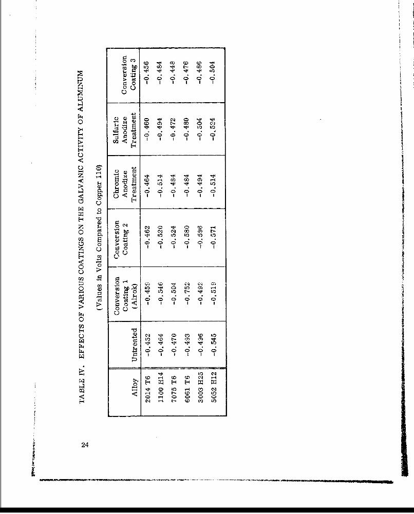
Table IV gives a comparison of the effects of the various coatings onthe galvanic activity of aluminum. These values are included in the practical Igalvanic series, but are listed in this chart because of their wide separation inthe series. This was not necessary with the coated magnesium samples sincethey are all listed together in the series.
No set pattern of variance in potential can be established from the effectsof the various coatings on the galvanic activity of aluminum. Although all valuesof the coated samples of 2014 T6 and 1100 H14 aluminum are higher than thoseof the uncoated samples, a set pattern is still not evident. The other four alloystested gave both higher and lower values for the coated samples. The highestpotential differences recorded resulted from conversion coating 1 and conversioncoating 2, but this was not true for alloys tested. Conversion coating 3 gavelower potentials with all alloys than did any of the other treatments.
23
0 0 CDs0 0 0
0 0
0 _ _ _
ý4, n - 0 00 C
0~ 4I
H t4> 0- - O q(t
0
0z ; 0 0 0q 0 0O
0 _ _-4 ý m t
00 0Ci K b' 0 ' ioo o .C C4 C;~ C'; C; C;
02
P-
oo0
to Cc t-
CD 0(00 0 0o
240

3. Electroplated Steel
The study of the effects of electroplated coatings on the galvanic
activity of steel included cadmium, chromium, nickel, electroless nickel,copper, zinc, brass, and tin platings. Silver, gold, rhodium, platinum andpalladium coatings were evaluated but were not included in the galvanic seriesbecause of their porosity. Rusting of the steel substrate was evident in severalcases, indicating defective plating. The prime substrate was AISI 1010 steel,although several stainless steel alloys were used for cadmium and chromiumplatings.
Table V shows the galvanic relationships of these platings to copper 110.Also included in this table are the measured potential values of zinc, severalbrasses, cadmium, tin, and nickel metals. This allows a comparison of thegalvanic response of the basic metal to the response when electroplated onto adifferent inetal, e. g., comparing the galvanic response of zinc metal to that ofzinc electroplated onto a steel substrate. Results showed that a metal gives
essentially the same galvanic response as the same metal electroplated onto asteel substrate.
4. Effects of Varying Degrees of Strength Level on the Galvanic Properties
of the Same Alloy
The data contained in Table VI were collected during the studyof the effects of alloy strength level on the galvanic activity of several aluminumalloys. Measurements had been made previously on four of these alloys, butthese measurements were repeated in order to give a good comparison of theseven alloys. Three types of surface treatments were used: chemical etch,steel wool, and sandpaper. Only one was used for the previous measurements.
From a close inspection of the table, it is evident that a set pattern can-not be established for the effect of strength level on the galvanic activity ofaluminum. However, in several instances, the voltage varied considerablybetween the two strength level conditions studied. Alloys 2024 (etched), 1100(sanded), and 7075 (all three surface treatments) showed the greatest variationdue to strength level. No appreciable difference is noted between the etched andsteel wool polished samples, but the sanded samples varied substantially inmost cases from the other treatments. Aluminum indicated greater variationsin galvanic activity, due to surface treatment, than other materials.
Stainless steel alloys 316, 321 and 347 were also used in the study of theeffect of strength level variation on galvanic activity. However, no definite con-clusions have been drawn from this investigation because of the difficulty
25

TABLE V. GALVANIC POTENTIAL MEASUREMENTS ION ELECTROPLATED SPECIMENS
-0. 793 Zinc on AISI 1010 steel-0.786 Zinc metal (AG40A)*-0. 557 Cadmium (brush plated) on AISI 1010 steel-0 554 Cadmium (brush plated) on 202 stainless steel-0. 534 Cadmium on AISI 1010 steel-0. 532 Cadmium (brush plated) on 321 stainless steel-0. 519 Cadmium metal*-0.333 Tin on AISI 1010 steel-0.301 Chromium on nickel on copper on AISI 1010 steel-0. 281 Tin metal*-0.250 Chromium on nickel on AISI 1010 steel-0. 209 Chromium on 202 stainless steel-0.203 Chromium on AISI 1010 steel-0. 194 Chromium on 410 stainless steel-0.192 Nickel on copper on AISI 1010 steel-0. 178 Chromium on electroless nickel on AISI 1010 steel-0. 169 Chromium on 430 stainless steel-0. 138 Electroless nickel on AISI 1010 steel-0.064 Nickel metal*-0. 043 Yellow brass*'-0.041 Naval brass*'ý-0.032 Brass on AISI 1010 steel-0.016 Low brass*
0.000 Copper 110 (Reference electrode)+0.086 Nickel on AISI 1010 steel
• Placed in chart for comparison to plated samples.
26

~c'
al Ca )
C;d
c~l in a)(
0 C0
C00 0Y 0~ 14 Q
tI-C Go ) OD iK <D Z)1i1
Hl C)I?9 C) 0 ) M _ _
U) - Ca *a)a(3) ýa) Q
r- t- <D2 0qýo
11 C(M CD~ 0
> ~ ~ a Q) ZC 4-- $Dz -ý C) CD C,. -
Hd I 0Ff) r_
C) ~ a) ~ a a) 0
XA~I~ ~ fD I ,- lt '. OI)U a.
l~27
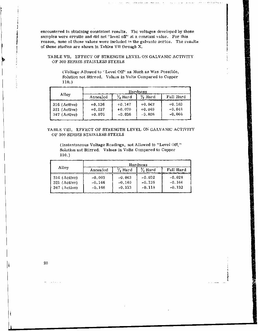
encountered in obtaining consistent results. The voltages developed by thesesamples were erratic and did not "level off" at a constant value. For thisreason, none of these values were included in the galvanic scrics. The r.esultof these studies are shown in Tables VII through X.
TABLE VII, EFFECT OF STRENGTH LEVEL ON GALVANIC ACTIVITY 4OF 300 SERIES T .STEELS
(Voltage Allowed to "Level Off' as Much as Was Possible,Solution not Stirred. Values in Volts Compared to Copper110.)
Alloy Hardness Fla
AAnnealed /4_Hard I Hard { Full Hard
316 (Active) +0. 136 +0. 147 +0.042 +0.103321 (Active) +0.037 +0.070 +0.049 +0.048347 (Active) 1-0.070 -0.036 -0.026 -0.008
TABLE VIII. EFFECT OF STRENGTH LEVEL ON GALVANIC ACTIVITYOF 300 SERIES STAINLESS STEELS
(Instantaneous Voltage Readings, not Allowed to "Level Off,"Solution not Stirred. Values in Volts Compared to Copper110.)
Alloy HardnessAlloy Annealed Hard I 2 Hard Full Hard
316 (Active) -0. 003 -0. 043 -0.032 -0. 028321 (Active) -0. 146 -0. 140 -0. 138 -0. 164347 (Active) -0. 166 -0. 113 -0.118 -0. 132
28
i

I ITABLE IX. EFFECT OF STRENGTH LEVEL ON GALVANIC ACTIVIIT
OF 300 SERIES STAINLESS STEELS
(Using Magnetic Stirrer at Half Speed, Voltage Allowed to "Level Off"as Much as Possible. Values in Volts Compared to Copper 110.)
Alloy Hardness__Alloy Annealed ,4 Hard 1/2 Hard Full Hard
316 (Active) +0.032 +0.032 +0.032 +0. 032321 (Active) +0. 142 +0. 142 -0. 142 +0.122347 (Active) +0.069 -0.022 +0. 004 J -0.008
TABLE X. EFFECT OF STRENGTH LEVEL ON GALVANIC ACTIVITYOF 300 SERIES STAINLESS STEELS
(Using Magnetic Stirrer at Full Speed, Voltage Allowed to "LevelOff' as Much as Possible. Values in Volts Compared toCopper 110.)
Alloy HardnessI Annealed 1/4 Hard i1/2 Hard I Full Hard
316 (Active) -0. 165 -0. 198 -0. 1'78 -0.153321 (Active) -0.078 -0.148 -0.078 -0.078347 (Active) -0.018 +0.012 +0.042 +0.042
The galvanic potential generated with titanium alloy 13 V-11 Cr-3 Al(heat treated: 1450°F for 30 min, water quenched, 900°F for 24 hr) was morenoble than the potential generated with this same alloy in the auedled coiuditioru(heat treated: 14500 F for 30 min, air cooled). Alloy 6 Al-4 V (heat treated:17000F for 30 min, water quenched, 9500 F for 4 hr) gave a less noble potential
than did the same alloy in the annealed condition. These results are shown inTable XI.
29

TABLE M. EFFECT OF STRENGTH LEVEL ON TIHE GALVANIC ACTIVITY
OF 13 V-11 Cr- 3.A ANID6 Al A V TTT A N'TITTIT" AT T I"'e
(Values in Volts Compared to Copper 110)
13 V-1i Cr-3 Al Annealed (1450'F for 30 min, air cooled; 0.436
Rockwell C hardness, 33.5) _
13 V-11 Cr-3 Al (Heat treated: 1450OF for 30 rain, water 0.498quenched, 900'F for 24 hr; Rockwell Chardness, 45.5)
6 A1-4 V Annealed (Rockwell C hardness, 36) 0.481
6 Al-4 V (Heat treated: 1700'F for 15 min, water 0,455quenched,950'F for 4 hr; Rockwell Chardness, 41.5)
5, Current Versus Weight-Loss Measurements
Theoretically, weight loss by galvanic corrosion is directly propor-tional to the amount of current per unit area flowing through a cell; however,some of the results given in Table XII do not follow this rule. There are severalreasons for this peculiar behavior. Polarization effects probably account formost of this, especially in the case of aluminum. The buildup of corrosionproducts, both on the electrbd.e. and in the solution, may result in anodic orcathodic polarization. The increase in alkalinity by these corrosion productsmay result in greater corrosion than would normally take place as a result ofthe cirrent generated by the cell. Recorded current values may be questionablesince readings were only taken intermittently and were not monitored continu-ously. Electrode size and length of co,rosion time may also account for these
Aresults.
4
6. Effect of Conducting Solutions on Galvanic Relationships of Metals as Compared
with Five-Percent Sodium Chloride Solution
Alloys representative of the various metal groups studied weretested in four different conducting solutions, including sodium chloride solution.Lowest voltage values were recorded with distilled water. Results from theother solutions were varied, depending on the alloy being tested. These resultsare shown in Table XIII.
30

TABLE XII.. CURRENT-WEIGHT LOSS MEASUREMENTF
Current (mamp x 10-2 IWeight Loss After After After
(g) Initial 19 hr 24 hr 115 hr
Magnesium - 2.45218 1240 1810 1890 750Szinc - 0.55570 2 6 r 348 335 267
Cadmium - 0.45330 300 220 188 110Steel - 0.34188 2S5 279 272 266Lead - 0. 16170 290 102 102 46.0
SAluminum - 0.09685 130 180 190 223
Copper - 0. 06955 16.3 24.0 24.0 31.0
Stainless steel - 0.00870 5.0 5.9 5.3 8.2Tungsten - 0.00830 10.4 8.4 7.1 4.5Nickel - 0.00338 2.0 2.0 2.4 2.9Molybdenum - 0.00320 5.1 5.8 5.0 1.2Niobium - 0.00318 2.3 0.06
Tantalum - 0.04Titanium 0,00070 1.1
TABLE XIII. EFFECT OF SEVERAL CONDUCTING SOLUTIONSON GALVANIC RELATIONSHIPS OF SEVERAL METALS
t COMPARED WITH FIVE-PERCENT SODIUM CHLORIDESOLU T1ON
(Values in Volts Compared to Copper 110)
1Stainless SteelEverdur (A.ctive) I itanium %1-U.E11Luuu1 Magnesium
655 347 5-5-5 6061 T6 AZ 91B
Distilled H20+0. 219 +0. 020 +0. 068 -0. 264 -0, 584
5% Sulfuric Acid+0.181 -0.132 -0.082 -0.369 -1.194
5% Sodium Hydroxide
-0.270 -0.119 -0.394 -1.264 -1.064
5% Sodium Chloride-0.007 +0,006 -0.1,4 -0.493 -1.064
31

Section V. FUTURE PLANS
Work now in progress is directed toward relating current density tocorrosion, which, in conjunction with the open-circuit potentials, will allow aclearer understanding of galvanic relationships. This study will climax withthe generation of a second galvanic series, which will relate changes in potentialdue to current flow. The current-weight loss studies have been modified to fitthis plan. No actual weight losses will be involved but may be calculated fromrecorded data, 'h dasired. The modifications resulted from discussion withDr. H. H. Uhlig, Professor of Metallurgy at Massachusetts Institute ofTechnology.
32

Section V1. CONCLUSIONS
The practical galvanic (voltage) series Is a valid guide or reference inthe selection of compatible materials. It gives a clear indication of the tendencyof metals and alloys to corrode, thus aiding In materials selection. The valueof the series lies in its practical applications. Direct measurements were madebetween each specific metal or alloy and the copper standard; thus the potentialbetween any two or more of the metals or alloys can be readily determined.Sodium chloride solution was used as the electrolyte, simulating a severe,practica. corrosion environment.
Based upon the recorded galvanic potentials, several of the coatings andplatings that were applied to mag.:esium, aluminum, and steel show high potentialfor enhancing galvanic corrosion protection. Dow 17 applied at 90 V and HAEapplied at 85 V rendered the magnesium most noble; i. e., less potential wasdeveloped between these two coatings and the reference electrode than betweenthe reference electrode and the other coatings and untreated magnesium samples.The most effective coatings on aluminum, indicated by potentials lower thanthose for the untreated samples, were: conveosion coating 3, chromic anodize,conversion coating 1 (Alrok) and sulfuric anodize on 5052 aluminum; conversioncoating 3 on 7075 aluminum; conversion coating 3, sulfuric anodize, and chromicanodize on 6061 aluminum; and conversion coating 3 on 3003 aluminum. Of themetallic coatings studied for steel, electroplated nickel showed the lowest degreeof galvanic activity.
In some metals, potential differences exist between different strengthlevels of the same alloy, and this difference should be given consideration whenselecting compatible mpterials. The direction of the variation in potentialdepends on the alloy.
Galvanic potentials vary with different conducting solutions; this should beconsidered when corrosion problems exist, or when selecting a couple for aparticul.r application.
33
I Imtw I I~. I

ISELECTED BIBLIOGRAPHY
1. ASTM Standards, 1961, Part 2, American Society for Testingand Materials, 1916 Race Street, Philadelphia, Pennsylvania.
2. Burns and Bradley, Protective Coatings for Metals, Second Ed.,Reinhold Publishing Corporation, 1955.
3. Daniels and Alberty, Physical Chemistry, Second Ed., John Wileyand Sons, Inc., 1961.
4. Edwards, Junius 1), , "Anodic and Surface Conversion Coatingson Metals," from The Metal Industry, 14 August 1942.
5. Lange, Norbert Adolph, Handbook of Chemistry, Ninth Ed., McGraw-Hill Book Company, Inc. , 1956.
6. Laque and Copson, Corrosion Resistance of Metals and Alloys, SecondEd., Reinhold Publishing Corporation.
7. Lyman, et al., Metals Handbook, Eighth Ed. , American Societyfor Metals, 1961.
8. Military Standard 171B (MR) , 20 February 1964.
9. Military Standard 186B (MI) , 30 March 1964.
10. Uhlig, H. H. , Corrosion and Corrosion Control, John Wiley and Sons,
Inc., New York, 1963.
11. Uhlig, H. 1. , Corrosion Fand.ocd , Sixth Ed. , John Wiley and Sons,Inc., New York, 1948.
12. Wiara, et al., Metal FinisThi-g 'Guide-Book Directory, 30th Ed. ,
Metals and Plastics Publications, Inc., Westwood, New Jersey, 1962.
34

UNCLASSIFIEDSecurit Classification;
DOCUMENT CONTROL DATA- R & D(SeOCWity Ci.Ieiticatlon of title, body of abstract and Indexinj annotalton muet be entered when the overall report Is clavilfled)
I TNG TI n . REPORT SCURIT CLASSICATION"tures and Me'lalS LanoratoryResearch and Development Directorate [UnclassifiedU . S,2 .C •ROUU. S. Army Missile Command GROA
Rete Arsenal Alabama 35809 NA3 .R TEPORi TI 1 LE
PRACTICAL GALVANIC SERIES
4. OESC• IP rIV9 NOTKS (Ty'pe oi report And Incluelve date*)
L. f fHORIS) (:.!rt name, iddcle Initial, test name)
Charles M. FormanE. A. Verchot
4. REPORT DATE 70. TOTAL NO. OF PAGES 7b. NO. OF REFS
10 October 1967 47 0SA. CONTRACT OR GRANT NO. On. ORIGINATOR'S REPORT NUWTBER(I)
A. PROJECT NO. (DA) 1C024401A328 RS-TR-67-11AMC Management Structure Code Nco.S5025.1.294 0b. OTHER REPORT NO(S) (Any other numb.er that may be assiged
this rsport)
SADIt. DISTRIBUTION STATEM"NT
This document is subject to special export controls and each transmittal to foreign governments
or foreign nationals may be made only with prior approval of this Command, ATTN: AMSMI-RS.
11. SUPPLEMENTARY NOTES IS. SPONSORING MILITARY ACTIVITY
None Same as No. 1
I1. ABSTRACT
The prime objective of this work was the development of a practical galvanic series of
metals and alloys to aid in the selection of compatible materials for missile systems. Thiswa8 accomplisl-hed by studying the various metals and alloys coupled with a 110 copper alloystandard as the reference electrode, and monitoring potentials with a self-balancingpotentiometric-type recorder. Each couple was partially immersed in a 5-percent salt(sodium chloride) solution.
The effects of coatings and platings on the galvanic relationships existing between metals
and alloys wiere also studied. Coatings and platings were studied with aluminum, magnesium,
and steel as the substrates.
Other studies included the effects on galvanic activity when strength levels within the samea-loy were varied, current versus weight-loss measurements, and the comparison of other
conducting solutions with the 5-percent sodium chloride solution used in the generation of this
series.
The study of the effect of strength level on galvanic activity showed that galvanic potentials
can exist between specimens of the same alloy at different strength levels. Also, the galvanicpotential varies with different conducting solutions.
D0% P 473~ NetLACK DO FORM .t.S. I JAN 64. WHIC4 ISDD 0 OSOL.T" POO ARMY UE,. UNCLASSIFIED 39Security Cieasification

UNCLASSIFIEDBecurity Classification
t4, LINK A LINK E LINK C
KEY WORDSROLE WT ROLE WT ROLE WT
Galvanic series of metals
Galvanic series of alloys110 copper alloyMetal coating, platings effects on galvanic
relationshipsGalvanic potential
II
40 UNCLASSIFIED
Security Clasifilcation
Related Documents


