Welcome message from author
This document is posted to help you gain knowledge. Please leave a comment to let me know what you think about it! Share it to your friends and learn new things together.
Transcript

New feature: Be. inners' corner
ELECTRON WORLD 91,191,9 INCORPORATING WIRELESS WORLD
JUNE 2000 £2.65
Radical views on THD
Efficient battery regulators
4-20mA loop calibrator
Trapezium waveform generators
Wireless RS232
Anew 100W Class-B topology
John Linsley-Hood updates his 30 wafter
Getting more from your scope
CS 833066
A REED BUSINESS PUBLICATION SOR DISTRIBUTION

Te net Tel: 02476 650702
Hewlett Packard 8642A — high performance R/1; synthesiser
(0.1-1050MHz) 3335A — synthesiser (200Hz-81MHz) £2400 Hewlett Packard 436A power meter and sensor (various) from £750 437B power meter and sensor (various) from £1100 Hewlett Packard 8753A network analyser (3GHz) from £2500 87538 network analyser (3GHz) from £3250 'S' parameter test sets 85046A and 85047A
available at £2000 & £3000 Wandel & Goltermann SPECIAL OFFER
PCM-4 PCM Channel measurement set (various options available) from £5500 Marconi 2305 — modulation meter £999 Marconi 6310 — programmable sweep generator
(2 to 20GHz) — new £3250 Hewlett Packard 5342A — microwave frequency counter
(500MHz-18GHz) ops 1 & 3 53708 — universal time interval counter
£4750
£700 £1500
OSCILLOSCOPES Gould 4068 150MHz 4 channe( DSO Hewlett Packard 54201A • 300MHz Digitizing Hewlett Packard 54600A - 100MHz - 2 channel Hitachi V152N2 12N222N302BN302FN353FN550BN650F Hitachi VI 100A • 100MHZ - 4 channel Intron 2020 - 20MHz. Dual channel D.S.O. (new) lwatstu SS 5710,SS 5702 - Kikusui COS 5100 - 100MHz - Dual channel Lecroy 9450A - 300MHz/400 MS/s D S.O. 2 channel Meguro MS0 1270A - 20MHz - D.S.O. (new) Philips PM3094 • 200MHz - 4 channel Philips 3295A - 400MHz - Dual channel Philips PM3392 - 200MHz-200Msis - 4 channel Tektronix 465 -100MHZ - Dual channel Tektronix 464/466 -100MHZ - (with AN storage) Tektronix 475/475A - 200MHz/250MHz - Tektronix 468 -100MHZ - D.S.0 Tektronix 2213/2215 - 60MHz - Dual channel Tektronix 2220 - 60MHZ - Dual channel D S.0 Tektronix 2235 -100MHZ - Dual channel Tektronix 2221 - 60MHz - Dual channel D S 0 Tektronix 2245A - 100MHZ • 4 channel Tektronix 2440 - 300MHzi500 MSis D.S.O. Tektronix 2445A - 150MHz - 4 channel Tektronix 2445 - 150MHZ - 4 channel . DMM Tektronix TAS 475 - 100MHZ - 4 channel Tektronix 7000 Series (100MHZ to 500MHZ) Tektronix 7104 - 1GHz Real Time Tektronix 2465/2465A/2465B - 300MHz.,350MHz 4 channel Tektronix 2430/2430A - Digital storage - 150MHz Tektronix 2467B - 400MHz - 4 channel high writing speed Tektronix TDS 320 100MHz 2 channel Tektronix TDS 540 500MHz 4 channel Tektronix 544A 500MHz 4 channel
SPECTRUM ANALYSERS Ando AC 8211 - 1 7GHz Avcom PSA-65A - 2 to 1000MHz Anntsu MS 2663A - 9KHz - 8 1GHz Anntsu MS 628 - 50Hz to 1700MHz Anntsu MS 610B 10KHz • 2GHz - as new Anntsu MS 710F - 100KHz - 23GHz AdvantenTAKEDA RIKEN - 4132 -100KHz • 1000MHz Hewlett Packard 3562A Dual channel dynamic signal analyser 64pHz - 100KHz Hewlett Packard 8505A • 1 3GHz • Network Analyser Hewlett Packard 8756A/8757A Scaler Network Analyser Hewlett Packard 853A Mainframe . 8559A Spec An (0 01 to 21GHz) Hewlett Packard 182T Mainframe . 8559A Spec An. (0 01 to 21GHz) Hewlett Packard 8568B - 100Hz - 1500MHz Hewlett Packard 8567A - 100Hz - 1500MHz Hewlett Packard 8754A - Network Analyser 4MHz-1300MHz Hewlett Packard 8591E 9KHz-1 8GHz Hewlett Packard 8594E 9KHz-2 9GHz Hewlett Packard 3561A Dynamic signal analyser Hewlett Packard 35660A Dynamic signal analyser IFR A7550 - 10KHz-1GHz - Portable Meguro - MSA 4901 - 30MHz - Spec Analyser Meguro - MSA 4912 -1MHz - IGHZ Spec Analyser Tektronix 2712 9fflz-1 8GHz (with tradung generator and video monitor mode)
£1500 £1250 £750
from £125 £900 £450
from £125 £350
£2250 £450
£1750 £1600 £1995 £350 £350
from £450 £650 £350
£1250 £600
£1250 £900
£2950 £1250 £1200 £995
from £200 from £2500 from £1250 from £1250
£4750 £850
£4500 £4950
£1500 £850
£7000 £1450 £3500 £5250 £1500
£5500 Keytek MZ•15,EC Minizap ESO Simulator (15ky - hand held) £1750 £1995 Marconi 10666 - Demultiplexer & Frame Alignment Monitor (140MBIT to 64KB1T)
from £1000 NEW £1750 £2750 Marconi 2610 True RMS Voltmeter £550 £2250 Marconi 6950/696069606 Power Meters 8. Sensors from £400 £5250 Philips 5515 - TN - Colour TV pattern generator £1400 £3995 Philips PM 5193 - 50MHz Function generator £1500 £1500 Leader 3216 Signal generator 100KHz - 140MHz - AM,FM/CW with built in FM stereo £4250 modulator (as new) a snip at £795 £6.750 Racal 1992 - 1 3GHz Frequency Counter £500 £3.995 Rohde 8. Schwarz SMY-01 Signal Generator (9KHz-1040MHz) £2250 £3250 Rohde (4 Schwarz NRV dual channel power meter & NAV Z2 Sensor £1250 £1950 Systron Donner 6030 - 26.5GHz Microwave Freq Counter £1995 £700 Tektronix ASG100 - Audio Signal Generator £750 £995 Wayne Kerr 3245 - Precision Inductance Analyser £1995 £5500 Wiltron 6747A-20 - 10MHz•20GHz - Swept Frequency Synthesiser £4950
Quality second-user test it measurement equipment NEW PHONE CODE FOR COVENTRY 02476
Radio Communications Test Sets Marconi 2955 Marconi 2958/2960 Antritsu MS555A2 Hewlett Packard 8922B (GSM) Schlumberger Stabilock 4031 Schlumberger Stabilock 4040 Racal 6111 (GSM) Racal 6115 (GSM) Rhode & Schwarz CMTA 94 (GSM) IFR 1200S
• e • -
in, •
z
,;,„ •
r lell ill Blom a CI - Cli O MOOolg 'm O OOOsigil c 01 Malmo is 0 coo • ize co
£2000 £2250 £1200 £6950 £3995 £1500 £1750 £3995 £5950 £2995
Fax 02476 650 773 Wendel & Goltermann TSA-1 system analyser (100Hz•180MHz) Wiltron 6409 - 10•2000MHz R F Analyser
MISCELLANEOUS Eaton 2075-2A - Noise Gain Analyser at £2750 Fluke 5100A/5100B/5200A - Calibration Units (various available) from £1000 Fluke 2620 Data Buckets
££650°°0 Fluke 8842A - Digital Multimeter Hewlett Packard 339A Distortion measuring set £1200 Hewlett Packard 435A . 435B Power meters from £100 Hewlett Packard 778D Dual-Directional Couplers £650 Hewlett Packard 3488A - Switch/Control unit £475 Hewlett Packard 3784A - Digital Transmission Analyser £4500 Hewlett Packard 3785A - Jitter Generator & Receiver £1250 Hewlett Packard 5343A - Frequency counter 26.5GHz £2000 Hewlett Packard 5385A - 1 GHZ Frequency counter £650 Hewlett Packard 6033A • Autoranrg System PSU (20v-30a) £750 Hewlett Packard 6622A - Dual 0/ system p su £1250 Hewlett Packard 6623A - Triple op system p.s.u. £1300 Hewlett Packard 6624A - Quad Output Power Supply £2000 Hewlett Packard 6632A - System Power Supply (20v-5A) £800 Hewlett Packard 6652A - 20V-25A System PSU £75000
Hewlett Packard 8112A - 50MHz Pulse Generator £2250 Hewlett Packard 83506 - Sweep Generator Mainframe £2000 Hewlett Packard 8656A Synthesised signal generator £850 Hewlett Packard 86566 Synthesised signal generator £1450 Hewlett Packard 8660D - Synttid Sig Gen (10 KHz-2600MHz) £3250 Hewlett Packard 8901B - Modulation Analyser £2750 Hewlett Packard 8903A, Band E - Distortion Analyser from £1250 Hewlett Packard 16500A . B - Logic Analyser Mainframes from £1000 Hewlett Packard 16500C - Logic Analyser Mainframe £3250 Hewlett Packard 16501A/B 8( C - Logic Analyser System Expander Frame from £2000 Hewlett Packard 37900D - Signalling test set Hewlett Packard 75000 VXI Bus Controllers Hewlett Packard 4193A - Vector Impedence Meter Hewlett Packard 5350B • 20Hz Frequency Counter Hewlett Packard 8657B - 100KHz-2060 MHz Sig Gen Hewlett Packard 8657D - XX DOPSK Sig Gen Hewlett Packard 8130A - 300 MHz High speed pulse generator Hewlett Packard 8116A - 50MHz Pulse,Function generator Hewlett Packard 1660A-136 channel Logic Analyser
£2750 £175C
£3750 £P0A £4750 £1950 £3995 £4500 £5250 £2250 £3995
All equipment is used - with 30 days guarantee and 90 days in some cases Add carriage and VAT to all goods.
Telnet, 8 Cavans Way, Binley Industrial Estate, Coventry CV3 2SF. CIRCLE NO. 101 ON REPLY CARD
Tel: 02476 650 70 Fax: 02476 650 773

• h. L. 433 COMMENT
Smetinn:,2 more than a virtual future?
435 NEWS • Scottish microdisplay initiative • IBM chips go a third faster • Maps on your mobile phone • Mobile-mast caution • E-mail phone • Copper IC processing
438 DOTTY.COM... Dot.commers have become such a constant source of fun and amusement that we will never be able to take them seriously again David Manners reports.
440 THD IS MEANINGLESS Looking at audio amplifiers from an RF designer's perspective Anthony New argues that THD figures are "irrelevant, irrational, and completely spurious." So what's the alternative?
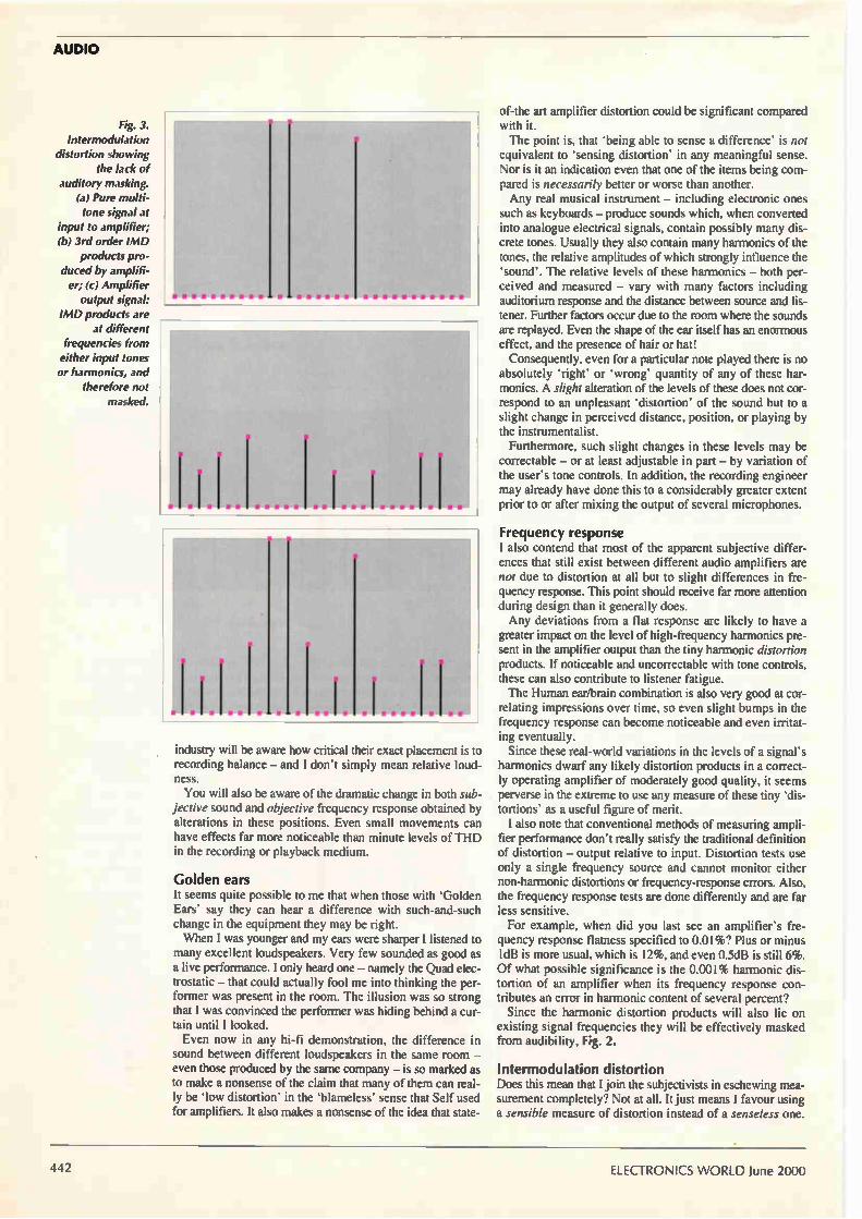
448 RS232 RADIO LINK Control equipment in a 50m radius around your computer using Pei An's wireless RS232 data link. Transmitted data packets have a unique address for directing them to any one of 1024 remote receivers.
456 CIRCUIT IDEAS • Simple phase-sensitive detector • Two transistor audio-visual alert • Mains flasher • Multichannel amplitude discriminator • Alternative neon tester • Simple FM broadcast receiver
460 EFFICIENT BATTERY POWER SUPPLIES Cyril Bateman shows how important subtle capacitor parameters are in gaining maximum efficiency from battery-powered regulators.
469 NEW PRODUCTS New product outlines, edited by Richard Wilson
480 JLH A LIFETIME IN ELECTRONICS John Linsley-Hood recalls the emergence of the IC and his first experiences with PLLs, the synchrodyne and cassette recorders.
486 A NEW 100W CLASS-B TOPOLOGY In a conventional Class-B amplifier, distortion rises with frequency. But it's at higher frequencies, where the ear is most sensitive, that you want the best performance to suppress the undesirable influences of cross-over switching. Russel Breden believes his reconfiguration 100W Class-B design solves that problem.
492 BECOME A TRAPEZIUM EXPERT There's any number of circuits for generating square, sine and triangular waveforms, but how often do you see a circuit for producing trapezium waveforms? Anthony Smith explains not only how to make trapezoidal waveforms, but also reveals why they can be so useful.
499 CALIBRATOR FOR 4-20MA INTERFACES After reeling at the price of a calibrator for 4 to 20mA loop interfaces, Darren Heywood decided to look into designing his own.
502 WEB DIRECTIONS Useful web addresses
505 LETTERS Audio power analysis, Easily-bared ends, Photodiode sensing, In defence of privatisation, Domestic thermocouples,
Blumlein.
466 BEGINNERS' CORNER Having come across electronics students that had had no experience of making and troubleshooting electronic circuits, Ian Hickman decided to show them how. Here's where he began.
July issue on sale 2 June
Photography : Mark Swallow
1.1 Sae a
Marker \
2 000000 MHZ V., -60 94 dB
5.) 4.1 1.1
nu. 1 411.11, '. 11111e 'Res MY VIM I Itélr Wi II am
As a means of judging an audio amplifier's performance, THD is pretty useless argues Anthony New. So what's the alternative? Find out page 440.
Are dot.com companies faking the mickey out of the financial world? David Manners says they are, on page 438.
June 2000 ELECTRONICS WORLD 4;1

i-4 -Y o u t PCIFP41411t Test & Measurement Instruments
WAvAftPCB.,POOktCebt Prototype PCBs
from your usual manufacturer for a fraction of the cost
£19 FREE Layout Software FREE Digital-Multimeter FREE PHONE 0800 389 8560
I. ail.' flfr Ort'Aii • u #711 iif
701165 701160 ! 701166 701166
(+353 (0)61 701170
FAX 701164
CIRCLE NO.104 ON REPLY CARL)
The NEW HF-08 Analog to Serial Converter 8 bit resolubon
Windows and DOS software evadable DVM Scope Spectrum. Logging
7 ranges .1 25V to +5 OV -2 5V ancl ±2 5V
Crystal controlled timing for accurate DSP
Simple to interface to your own software
/ Low Cost - just £69.33 incl vat
12 bit module coming soon
RF Instruments
EMC Equipment
ForF Instruments Phone: 01420 590000
e-mail: [email protected]
Metered bench power supplies Up to 60V and 6A
Prices from £127 inc. VAT
.) •374,—
Data Logging & Acquisition
Handy DIM / Scope Counter/Timer TTL Sig. Gen. £199 inc. VAT
Visit our Web Site for full details:
www.hf-inst.co.uk
CIRCLE NO.105 ON REPLY CARD
The science lab in a PC Experrment, Ideas for DrDAQ
. FIKSeeng Lets
. Pawn Chorys
• SOUXI waveforms
Sou. Decay Soensl Inman's,
Sound erevefonos «te ale
Ug. ae.e/ Ce,reele as Insutabon .
0.6 Base Teal«. we Se. Ron lui E zolhenne Beacom.. I Entbethenr. %ocean' Ds, sn0 Het ,..es Fernwft•Pon ot Gram I
Capetator cnaroaddiaelt Infra reel remote coned Out.. &as*. col ct Heal insulabon u re GM. 'gamma
9. 15 1.• team
-3
,r7r1 XIrOS.jE, j oct..
41% has.. SI Slims..
Only £59!
The DrDAQ is a low cost data logger from Pico Technology. It is supplied ready to use with all cables, software and example science experiments.
DrDAQ represents a breakthrough in data logging. Simply plug DrDAQ into any Windows PC, run the supplied software and you are ready to collect and display data.
DrDAQ draws its power from the parallel port, so no batteries or power supplies are required.
Output
Voltage
Resistance
Light level
Temperature
External sensors pH Microphone
V Very low cost
✓ Built in sensors for light, sound (level and
waveforms) and temperature
✓ Use DrDAQ to capture fast signals (eg
sound waveforms)
✓ Outputs for control experiments
✓ Supplied with both PicoScope
(oscilloscope) and PicoLog (data logging) software
Tel: 01480 396395, Fax: 01480 396296, E:mail: post@ Icotech.com, Web: www.drda.com
CIRCLE NO.106 ON REPLY CARD
ELECTRONICS WORLD June 2000

Something more than a virtual future? EDITOR
Martin Eccles
020 8652 3614
CONSULTANTS
Ian Hickman
Philip Darrington
Frank Ogden
EDITORIAL ADMINISTRATION
Jackie Lowe
020 8652 3614
EDITORIAL E-MAILS
GROUP SALES EXECUTIVE
Pat Bunce
020 8652 8339
ADVERTISEMENT E-MAILS
ADVERTISING PRODUCTION
020 8652 8339
PUBLISHER
Mick Elliott
EDITORIAL FAX
020 8652 8111
CLASSIFIED FAX
020 8652 8938
NEWSTRADE ENQUIRIES
020 8261 7704
ISSN 0959-8332
For a full listing of
RBI magazines: httpiiwww.reedbusiness.com
REED BUSINESS
glW INFORMATION
SUBSCRIPTION HOTLINE
Tel, (0) 1444 475662
Fax, (0) 1444 445447
SUBSCRIPTION QUERIES
Tel 01444 445566
Fax 01444 445447
The UK electronics industry is making a uelcome return to a practice it was once particularly good at.
That is manufacturing ground-breaking products. This news that the industry is returning to its manufacturing
roots could not have come at a more opportune moment.
The electronics sector has been dragged into the much-
hyped dot.com stock market investment phenomenon.
That's good news for those individuals lucky enough to
find themselves turned into an over-night millionaire« on the strength of a stock market flotation. But it is not doing
much for the longer term strength and competitiveness of
the electronics industry as a whole. Indeed the more thoughtful entrepreneurs in the
Cambridge start-up belt fear that the credibility of the
high-tech start-up could eventually be damaged by the misplaced faith of ill-advised City investors in the
dot.com phenomenon. The good news is that behind all
the smoke and mirrors created by dot.com mania there
are encouraging signs of something more permanent growing in the grass roots of the industry's
manufacturing sector.
Just before Easter an Oxfordshire-based firm Bookham Technology was valued at £2.9bn in its initial public offering (IPO) on the London Stock Market. Nothing too
surprising about that in the current climate, except that Bookham is an electronic component manufacturer.
Bookham's value as a business is based on a technique
for manufacturing low cost opto-electronic components used in optical fibre communications networks. It is not
surprising that a group of UK-based engineers should
come up with a world-class semiconductor component
technology.
However, it is surprising that a UK-based start-up has actually made a success of manufacturing its products and is selling them to blue-chip multinationals around the
world. What is even more surprising is that the City investors have recognised the potential in a company like
Bookham Technology, without being frightened away by
the inevitably high up front investment required for any
new manufacturing operation. Even the Financial Times pointed out that Bookham
Technology, despite making a loss this year. has a more solid under-pinning than many recent high-tech stock
market launches. Investing in electronics manufacturing is a long term
venture and happily it is starting to happen once again in
the UK.
Another recent example of this 'grass-roots' investment is particularly pertinent and welcome. The government is
to put £40m into a new electronics manufacturing collaborative programme between industry/universities.
The scale of this investment is obvious when you
remember that the gosernment put a mere L3m into its
three year Microelectronics in Business (MiB) electronics
design programme.
Such is the relative size of the government's new manufacturing initiative that some of the civil servants
are worried that the achievements of the MiB programme
will be dwarfed and forgotten in comparison.
This is great news for UK electronics. At last the
government has realised that it must tackle the skills shortage and opportunity bottleneck at the manufacturing
end of the high-technology revolution.
Another established electronics manufacturer. Marconi
is investing £40m in a new graduate and engineering skills programme in partnership with Cambridge
University. Microsoft, Rolls-Royce and AT&T have all invested in
Cambridge University, and last year British Aerospace, another big engineering trainer in the 1970s, launched
plans for its own "engineering university".
For so many years the firms have been warning and about the shortage of skilled designers, but few were
prepared to make the sort of financial commitment
needed to address the issue. What is significant about Marconi's collaboration and
investment in Cambridge-University is that it shows one
major electronics employer is prepared to do something
about the skills shortage. What makes the initiative all the more impressive is
that Marconi is unlikely to see any tangible return on its investment for three, maybe five years.
You can have all the dot.com flotations you like, but if
Tony Blair wants to encourage new industries to create
the wealth once taken for granted from industries like
car-making and ship-building then he must rebuild some • industrial foundations for the high-tech sector. That means being able to manufacture the electronic products which spring from the innovative ideas being produced
like crazy on the regional science parks. At different ends of the corporate scale that is exactly
what companies like Bookham Technology and Marconi
are doing. It would be foolish to believe that manufacturing is
fashionable again. Too much has been done in this country in the last 20 years to undermine that belief. The
digital revolution continues to be driven by fabless design
house like ARM and IPO obsessed dot.com individuals. But at least Bookham's successful market flotation and
this latest manufacturing initiative from the government
signals that the rebuilding of the UK's electronics
manufacturing industry is well on the way and is entering
a new phase of optimism. Richard Wilson
Electronics World is published monthly. By post, current issue £2.65, back issues (if available £3.00). Orders, payments and general correspondence to L333, Electronics World, Quadrant House, The Quadrant, Sutton, Surrey Sh12 SAS. Tlx:892984 REED BP G. Cheques should be made payable to Reed Business Information Ltd Newstrode. Distributed by Marketforce (UK) Ltd, 247 Tottenham Court Road London W1P OAU 0171 261-5108. Subscriptions: Quadrant Subscription Services, Oakfield House Perrymount Road, Hoywards Heath, Sussex RH16 3DH. Telephone 01444 445566. Please notify change of address. Subscription rates 1 year UK £36.00 2 years £58.00 3 years £72.00. Europe/Eu 1 year £51.00 2 years £82.00 3 years £103.00 ROW 1 year £61.00 2 years £98.00 3 years £123
Overseas advertising agents France and Belgium- Pierre Mussard, 18.20 Place de la Madeleine, Paris 75008. United States of America: Ray Barnes, Reed Business Publishing Ltd, 475 Park Avenue South, 2nd Fl
New York, NY 10016 Tel, (212) 679 8888 Fax, (212) 679 9455 USA mailing agents: Mercury Airfreight international Ltd Inc, 10(b) Englehard Ave, Avenel NJ 07001. Periodicles Postage Paid at Rahway NJ Postmaster. Send address changes to above Printed by Polestar (Colchester) Ltd, Filmsetting byllTypogrophics Ltd, Unit 4 Baron Court, Chandlers Way, Southend-on-Seo, Essex SS2
55E.
© Reed Business Information Ltd 1997 ISSN 0959 8332
June 2000 ELECTRONICS WORLD 433

PIC Basic Write your PIC programs in BASIC! - No STAMP REQUIRED!
* PIC Basic - £49.95 Qui I,,', Lod rr.r,r, ,,r PIC BASIC is a true compiler providing faster
execution and shorter programs than BASIC stamp interpreters, built in I2C routines and serial commis upto 115K Baud and full BASIC STAMP compatibility make wnting for
the Microchip PICrnicro's easy! PIC BASIC compiles your basic language programs to Microchip Hex format for use with In-circuit emualtors or for programming directly into the PIC CHIP Supports PIC12C67x. PIC14Cxxx, PIC16C55x. 6xx. 92xand 16F87x
Full documentation with syntax examples are provided in the 168 page user manual A technical support mail,ng list is provided for life time support
• PIC Basic Pro - £149.9% the PIL BASIL, Pro Loon,. r .cooructoon set is compatible with the Basic Stamp II providing additional functionality over PIC BASIC. feature like LCD read Write, fully customisable Sena' in / out (Create a serial LCD display dnver in miniutes) Full de-6.12 facilities compile with debug to produce assembly commented with your Basic commands PIC BASIC and PIC BASIC PRO compile tight efficient code without the use of a basic interpreter Supplied with a 168Page manual. explaining each command and worked examples FREE PIC Macro compiler, FREE Programmers File Editor, FREE Windows Front End PIC BASIC PRO Includes samples programs and code to support Smart card read&write
Download the full 168 page PIC BASIC MANUAL and sample programs
http://www.picbasic.co.uk Order Online via our secure server
http://www.crownhill.co.uk
• Low cost programmer for PIC12Cxxx, PIC12CExxx, PIC14Cxxx, PIC16C505. 55x, 6es, 7xx,84, 9xxPIC 16CE62x and PIC16F87x
• ZIF adaptors are available for 8/18 in 40/28Pin DIL, 8,18 and 28 SOIC, 44 Pin MOFP 44 and 68 Pin PLCC
• Powered by 20 9V batteries or AC adapter • Connects to PC parallel port • Upgradable software is supplied for future PIC Micro's • FREE 8051 style PIC Macro compiler
£35 When purchaseç_ls< -
with PIC BA«
Parallel port extension cable - £5.95 40Pin ZIF socket - £22.50 8/18Pin ZIF Socket - £22.50 PIC8 Prototype hoard - £4.50 PIC18 Prototype hoard - £5.50 PIC64 Prototype hoard - £8.50 peces ate
PIC Real-Lime Real-time Emulator' and Programmer
PIC 16F811 In Circuit ..i• t • it ii.ggerhowaird pro.....,
.For PIC16F87X (emulates most PIC16C6X/7X devices] z In-Circuit run time debugging z Real Time code execution 32Khz to 20Athi real time operation z High Speed Parallel port interface z 2.5V to 6.8 operating range E Built in device programmer Faun, Step, Run to Cursor etc EConditional Animation Break FSoftware animation trace captures 3 user defined variables
in addition to opcode, W, Status. FSR registers and corresponding instructions.
izSource Level and symbolic debugging EBuns under PICICD WE E win95/98 or NT] or ?ARAB RISupplied with ICD debug module. Preto board.
40Pin and 28Pin emulator headers, Cables IDE software and user guide
<it\ M ICROCHIP PIC 16F84 /04p - £1.90 PIC 16184 /04so - £2.00 PIC 16F84 /100 - £3.95 PIC 16C622 /04p - £2.50 PIC 161871 /04p - £5.50 PIC 16F877/200 - £6.00 PIC 161816 /04p - £4.50 PIC 161814 /0411- £4.50 PIC 161873 /04p - £4.50
PIC 12C508A - £0.63 PIC 12C509A - £0.63 24=16 - £0.75 24/C16 so - £0.95 241.1232 - £1.50 244e.C4 £1.50 2,Etso
•M peat ale ••
PIC Micro CD-ROM over 1.2Gb of into £10 inc PaP ami VAT
Packed with information, data sheets, application notes, programs diagrams and tutorials. Includes TETRIS and PING PONG with sound and video out of a single PIC 16F84. Basic language assembly routines and macros for hundreds of commands. Data sheets on thousands of devices, micro's, memory and support chips.
LCD DISPLAYS 16x2 line super twist displays - £7.50 ea
Ktals and Resonators f 4Mhz and 20Mhz from 45p
PIC16x84 programmer Kit WINDOWS Driver - £15.00 inc PaP + VAT Programs the popular PIC1684 and 24 series serial memory devices.
Connects to the serial port ol PC unto pentium loot P2 or P31 and requires
NO External power supply. The KIT Includes Diagram. layout. High Quality PCB
and all componenets, software on 3.5 - FO
SMARTCARD DEVELOPMENT SYSTEM Read- and Vina «ton Smatfads- crs
krosal PlISC matt !
Pee Incipies:
Prciassicoal cad Reader Wrildr (CheOlae WO,
Awed Smart Cards (3 pak
Sares al source ade in VR3,4,54 C and Deei.
Examples A,c9s to Read aid Wide to Smart Cads and GUI Dads
DocumentOr aNi detale2 W1,,INs DLL desc!o-
Www.towitoko.co.uk
etalWrog 48LV er‘o Low Cost - High Performance
Intelligent Universal Device Programmer
Includes: Connection cable
Diagnostic POD
User Manual
PC Sotware Driver
240VAC/12V adaptor
CE certified
Universal Serial [[prom programmer
£49.9
Plugs into parallel port ol your PC
Adaptors !or TSOP. PSOP. QFP. SOIC. PICC
True NO Adapter Programming mito 48 Pins
Programs and Verifies 2.2.1.3.3.3 a 5V devices
FREE software updates 3 Year Warranty
PreProm UNIVERSAL Worn Programmer Adaptors for TSOP PSOP QFP SOIC MCC
Adaptors for Microprocesors
Adaptors for Eeprom
Emulator adatar e
Crownhill Associates Limited
VISA 32 Broad Street Ely Cambridge Cb7 4PW Tel: 01353 666709 Fax: 01353 666710
ORDER ON-LINE WWW.crownhill.co.uk
CIRCLE NO. 107 ON REPLY CARD

up DATE Scottish microdisplay initiative could see the UK featuring in the bigger picture Scottish universities are aiming to put a solid academic base under the UK microdisplay industry. The proposed initiative is called
CUPID, for Combined Universities Participating in Displays. "The group forming CUPID is essentially on the East Coast of Scotland, but we are hoping to make it a UK-wide initiative," said David Vass, Professor of applied physics at the University of Edinburgh, "We are keen to promote the UK microdisplay industry." At the moment there are five
universities expressing interest. "We are all speaking to each other, although we do not have a formal agreement yet," said Vass. The universities are: Edinburgh, Napier, Heriot-Watt, Abertay Dundee and Dundee and the aim is a long term collaboration. "The idea is to bring together expertise in microdisplays over the next 10 to 15 years," said Vass. Among these, Abertay brings
experience sometimes overlooked in
Possible partners at a glance
• University of Edinburgh — LCD microdisplays since the early eight-ies.
• Napier University — chemistry of LCD and light emitting polymers, and optical assessment.
• Heriot-Watt University — applications of display and the interface architecture.
• University of Abertay Dundee — human factors and performance characteristics
• University of Dundee — amorphous silicon field emitters.
technology-based research projects: ergonomics. "One of the major advantages of is the human factors element," said Vass.
Microdisplays, displays under 25mm across, offer a way of presenting highly detailed visual information to mobile users without the bulk of conventional displays. Optics focus the image in such a way that when the display is held, or worn, close to the eye, the image fills the visual field in the same way a large TV does. Usable resolution can be far
higher than existing PDAs and other conventional mobile information devices.
Industry interest in microdisplays is such that the Society of Information displays, an international organisation, is making them the main theme of its 2000 conference.
Microdisplays take many forms. Specifically CUPID will be looking at "Active backplanes driving LEDs or light-emitting polymers, based on standard semiconductor processing, which can be obtained from various ASIC foundries," said Vass.
IBM chips go a third faster on low-k IBM Microelectronics is to boost its chip speeds by a further 30 per cent when it starts using a low-k dielectric next year. The material is used as an
insulator between layers of metal interconnect in a chip. A lower value for k means reduced capacitance between wires, leading to increased speed and reduced crosstalk.
"It's a very large improvement compared to what most people use which is FSG," said Michel Rivier,
a technical specialist at IBM. Licensed from Dow Chemical, the
low dielectric constant material has a k of 3, significantly better than that of FSG, the most common material used today, with a k of 4. The first process to use the
material is called Cu-11, which uses copper for interconnect (see page 46). Using 0.13µm lithography, the process will result in transistor channel lengths down to 0.08µm.
"Right now it's in pre-production," said Rivier.
Maps on your mobile? Yeoman group, the mobile navigation firm, has entered an agreement with Ordnance Survey to co-develop standards for mobile navigation systems. Yeoman said it is developing an
operating architecture for mobile navigation systems, which should allow consumers access to map databases via WAP phones.
"This is a significant step towards reaching a complete mobile naviga-
tion offering," said Vincent Geake, Yeoman's chief technical officer. Yeoman also said it has made an
unsolicited offer for UK firm Laser-Scan of one new Yeoman share for every Laser-Scan share with a cash alternative of 42.9p per share. Laser-Scan has developed software to support a mapping database. "The Yeoman board believes that
the enlarged group will significantly enhance value for shareholders of
Welcome medicine for sick mines... The Japan Alliance of Humanitarian Demining Support (JAHDS) has presented the HALO Trust with equipment specifically designed to support mine removal efforts at Angkor Wat in Cambodia. Mine Eye was a joint development by companies including sensor-designer Omron. lAHDS was started by Hiroshi Tomita after he discovered that 'butterfly' mines in Angola were deliberately shaped to entice children to play with them.
both companies because their tech-nologies in the area of mobile naviga-tion and geographical information are complementary," said Yeoman in a statement.
June 2000 ELECTRONICS WORLD 435

NEWS
, Scotland urges mobile-mast caution The Transport and Environment Committee of the Scottish Parliament has recommended that a precautionary approach regarding health issues should be adopted when siting mobile phone masts.
If its recommendations are accepted then full planning control would be introduced for masts.
In its 'Inquiry into Telecommunications Developments' report admits there is no conclusive
scientific evidence of a health risk, but it believes the level of public concern justifies a precautionary approach. This would mean schools, hospitals
and residential areas would be considered unsuitable sites.
It also wants the environmental impact to be more carefully considered, with initiatives such as mast and site sharing used. The possibility of requiring a national roaming agreement to he made is also
Amstrad rings in the e-mail phone Amstrad has finally unveiled the mass-market Internet product which the company has been working on for over a year. The 'e-m@iler' is intended to bring e-mail to
the mass market without the need for a PC. The unit was developed in collaboration with BT and consists of a phone unit with keypad and LCD screen. The unit can send and receive e-mail, holds up
to 700 contact details and has automatic e-mail notification and collection. It also provides a digital answering machine and fax facilities.
"I see the e-m@iler becoming the all-in-one communications centre' in the home. It is the blockbuster product Amstrad has been working on for the last eighteen months and which the market has been waiting for," said Sir Alan Sugar, Amstrad's chairman. The e-m@iler is being sold at a subsidised
price of £79.99 and is apparently available in the High Street already.
an option. Similar recommendations could soon
appear before the UK government. A report from a similar inquiry is expected to be presented any time now by the Independent Expert Group on Mobile Phones. The group was set up to look at
concerns about the health effects of mobile phones, assess existing research and give advice based on that knowledge.
Solutions waiting for a problem European electronics companies are flocking to join intellectual property Web site yet2.com.
Started in February by 30 US firms, yet2 is a shop window for intellectual property that companies have invented, but have no use for. The most recent additions from
Europe are BT, Bosch, Philips Electronics and Siemens, together with Japan's Toshiba.
"Large corporations are sitting on huge and growing reserves of great ideas that never see the light of day or are used once only and never again," said Chris de Bleser, CEO of Yet2.com. US founding sponsors of yet2
include 3M, Dow, DuPont, Honeywell, Polaroid, Rockwell and TRW.
Doubts cast over benefits of copper IC processing Using an all-layer copper process to make a chip showed 'no difference' in performance compared to the same chip made in aluminium, says TSMC's top scientist. The finding could affect the
widespread use of copper processing for the upcoming
Engineers' pay settlements hit by strong pound hngineering pay settlements have remained at a historically low level of 2.4 per cent for three months in a row. The latest survey findings from the Engineering
Employers' Federation (EEF) shows that nearly one in eight settlements were pay freezes in the three months to the end of February 2000. The EEF said this situation is due to the continuing
high level of sterling.
0.15pm generation of process. According. to the main
proponents of copper processing, IBM and Motorola, copper gives an added performance advantage of 20 per cent over aluminium because of copper's lower resistivity. Asked if TSMC had made
demonstrator chips to compare the performance of copper with aluminium, Dr Shang-Yi Chiang, vice-president for R&D at TSMC, replied: "A customer who ordered copper saw no difference in performance." Dr Chiang emphasised that the
process involved, which was TSMC's 0.15pm all-layer copper process, did not use low-k dielectrics. TSMC's low-k dielectrics process is currently in product qualification, which is due to be completed in June.
"Also, the problem was that it was the same design — the same
layout," said Chiang, "you ha % e to optimise the design to take advantage of the copper process."
Accordingly, Chiang believes: "We do not expect a very large demand for copper until the 0.13pm process when customers have learnt how to optimise their designs to use copper." Copper processing has been
promoted by IBM as the answer to limitations in traditional aluminium processing. Motorola is in the forefront of copper processing and licensed its process to Chartered Semiconductor of Singapore. AMD says it will use copper
processing on some layers of its Athlon microprocessor. Although Intel has dubbed its latest generation of microprocessors 'Coppermine' it does not use copper to make them and has said it does not think it will use copper until the 0.13pm generation.
4 th ELECTRONICS WORLD June 2000

mum. rriePieScope HS801 PORTABLE MOST
ABRITARY WAVEFORM GENERATOR
STORAGE OSCILLOSCOPE-SPECTRUM ANALYZER-
MULTIMETER-
TRANSIENT RECORDER-
The HS801: the first 100 Mega samples per second measuring instrument that consists of a MOST (Multimeter, Oscilloscope, Spectrum analyzer and Transient recorder) and an AVVG (abritary waveform generator). This new MOST portable and compact measuring instrument can solve almost every measurement problem. With the integrated AVVG you can generate every signal you want.
The versatile software has a user-defined toolbar with which over 50 instrument settings quick and easy can be accessed. An intelligent auto setup allows the inexperienced user to perform measurements immediately. Through the use of a setting file, the user has the possibility to save an instrument setup and recall it at a later moment. The setup time of the instrument is hereby reduced to a minimum.
When a quick indication of the input signal is required. a simple click on the auto setup button will immediately give a good overview of the signal. The auto setup function ensures a proper setup of the time base. the trigger levels and the input sensitivities.
-.31101.Mumm-
• The sophisticated cursor read outs have 21 possible read outs. Besides the usual read outs, like voltage and time. also quantities like rise time and frequency are displayed.
• Measured signals and instrument settings can be saved on disk.This enables the creation of a library of measured signals. Text balloons can be added to a signal. for special comments. The (colour) print outs can be supplied with three common text lines (e.g. company info) en three lines with measurement specific information.
• The HS801 has an 8 bit resolution and a maximum sampling speed of 100 MHz. The input range is 0.1 volt full scale to 80 volt full scale. The record length is 32K/64K samples. The AVVG has a 10 bit resolution and a sample speed of 25 MHz.The HS801 is connected to the parallel printer port of a computer.
The minimum system requirement is a PC with a 486 processor and 8 Mbyte RAM available. The software runs in Windows 3.xx / 95 / 98 or Wndows NT and DOS 3.3 or higher.
TiePie engineering (UK). 28 Stephenson Road, Industrial Estate. St. Ives. Cambridgeshire. PE17 4VVJ, UK Tel. 01480-460028: Fax: 01480-460340
TiePie engineering (NL). Koperslagersstraat 37. 8601 VVL SNEEK The Netherlands Tel: +31 515 415 416: Fax +31 515 418 819
Web: http://www.tiepie.n1
CIRCLE NO. 108 ON REPLY CARD

Doity.com... Dot.commers have become such a constant source of fun and amusement that we
will never be able to take them seriously again. David Manners stifles his giggles.
Smirk at those who
ramble on about
dot.com fortunes -
often the same ones
who talk about
house prices. Giggle
at the discomfort of
life-long
money-grubbers
seeing youngsters
making instant
fortunes. Ridicule
the moans of those
who didn't get
shares, or enough
shares, in the latest
IPO. These Sad Acts
give us a good
laugh.
Not since Screaming Lord Sutch have we had so much fun as we're having with the dot.com companies.
His late Lordship took the mickey out of the political world; the dot.coms are taking the mickey out of the financial world.
Seeing solemn money-men trying to add their patina of logic and justification to the dottiness of the dot.com world is hilarious. In future they are going to find it hard to convince us of the authority of any of their analyses. The only rational explanation for the dot.com
phenomenon is that they resurrected the greed/fear frenzies of the past: 'Tulipmania' in the 1630s, when Dutchmen paid the price of a house for a tulip bulb; the South Sea Bubble of 1720; the 1849 Gold Rush; the 19th century boom/bust in railway shares; the 1970s Australian Mining Boom led by Poseidon shares; the 1988/9 UK Housing Boom; Japan's 1980s 'Bubble Economy' when Tokyo land prices were so high that the Imperial Palace's gardens were worth more than the State of California.
In all these greed/fear frenzies, the fear of being left out made people take leave of their senses and buy pigs-in-pokes at crazily-escalating prices, and greed made people over-borrow to buy assets they could not afford, gambling on massive profits from the expected price rises, and ruining themselves and their families in the ensuing crash. The same is happening with the Internet and the
mania to invest in dot.com companies. But, unlike some of the popular frenzies of the past, the dot.com scenario has a calculated, professional element as traditional financial interests seek to get their share. We are encouraged to think that dot.com
companies are started by sparky young people with nothing except a 'good idea'. How far from the truth that is. One of the backers of the recently floated
lastminute.com was Intel, whose PR initiatives
helped create lastminute's high public profile in the months preceding the launch. The founders are not the innocent young techies
operating from a garage of an earlier generation - lastminute's founders are highly articulate, well-funded Oxford graduates with well-honed skills in making sophisticated financial presentations.
Venture capital - once jealously hoarded by high-tech start-up companies for innovative product development - tends to be spent by dot.coms mostly on publicity rather than on developing a service or a product. Some of the dot.com companies are spending on
publicity at the rate of £1m a month — the money coming from venture capitalists wanting to make a quick killing through an early public offering on the stock market. The message of the venture capital-backed
dot.com founders is usually simple — grab the IPO money and run. For all those who are not overwhelmed by the
fear/greed frenzy of the dot.com phenomenon, it can be a fun thing to watch.
Smirk at those who ramble on about dot.com fortunes — often the same ones who talk about house prices. Giggle at the discomfort of life-long money-grubbers seeing youngsters making instant fortunes. Ridicule the moans of those who didn't get shares, or enough shares, in the latest IPO. These Sad Acts give us a laugh.
There are, of course, many fine and worthy Web sites, some delivering wonderful things, but the venture capital-backed dot.com is often a greedy, flaky beast to be ridiculed and exploited. What they are good for is: 1) To make a quick
killing; 2) To create an inflated share valuation which can then be used to take over proper companies with revenues, employees, assets and profits; 3) To exploit their capital-raising abilities to provide useful products and services. •
ELECTRONICS WORLD June 2000

BOOK T • BUY
ANTENNAS AND PRoPF!GwAIRTEILOEsNs COMMUNICATION
SYSTEMS
"Çitt,'Zros 0'41 -
CONTENTS Introduction: The Wireless Communication Channel • Properties of Electromagnetic Waves • Propagation Mechanisms • Basic Propagation Models *Terrestrial Fixed Links • Satellite Fixed Links • Macrocells • Shadowing • Narrowband Fast Fading • Wideband Fast Fading Microcells • Picocells • Megacells • Diversity • Equalisers • Adaptive Antennas • Future Developments in the Wireless Communications Channel • Appendices
416pp £39.95
Post your completed order form to:-
Jackie Lowe, Room L333, Quadrant
House, The Quadrant, Sutton, Surrey,
SM2 5AS
Phone your credit card order:
020 8652 3614
Fax your completed order form to
020 8652 8111
email: [email protected]
POSTAGE FREE
For air delivery add £5.50 postage
Antennas and Propagation for Wireless Communication Systems Antennas and propagation are the key factors influencing the robustness and
quality of the wireless communication channel. This book introduces the basic
concepts and specific applications of antennas and propagation to wireless
systems, covering terrestrial and satellite radio systems in both mobile fixed
contexts.
Including:
• Illustrations of the significance and effect of the wireless propagation channel
• Overview of the fundamental electromagnetic principles underlying
propagation and antennas
• Basic concepts of antennas and their application to specific wireless systems
• Propagation measurement modelling and prediction for fixed links, macrocells,
microcells, picocells and megacells
• Narrowband and wideband channel modelling and the effect of the channel on
communication system performance
• Methods that overcome and transform channel impairments to
enhance performance using diversity, adaptive antennas and
equalisers.
Antennas and propagation is a vital source of information for wireless
communication engineers as well as for students at postgraduate or senior
undergraduate levels.
Distinctive features of this book are:
• Examples of real world practical system problems of communication system
design and operation
• Extensive worked examples
• End of chapter questions
•Topical and relevant information for and about the wireless industry
How to pay J I enclose a cheque/bank draft for £
(payable to Reed Business Information)
Please charge my credit/charge card
J Mastercard a American Express J Visa J Diners Club
Credit Card No: Expiry Date:
Signature of Cardholder
Send my order to: (please use capitals)
Name
Address
Post Code Tel:
Fax: Date
Please allow up to 28 days for delivery

Arecent article by Ian Hickman showed how to mea-sure total harmonic distortion, or THD, down to lev-els below 0.001%. This achievement is worthy of
applaud for its technical challenges, yet I cannot help mar-velling at the enormous waste of effort that has been made over the years on such an irrelevant, irrational, and com-pletely spurious figure as THD.
Irrelevant? Irrational? How so? And how can a figure used so frequently in audio design be spurious? The latter is a very good question, and one which I have not been able to answer.
"THD is meaningless" Looking at audio amplifiers from an RF designer's perspective, Anthony New argues that THD figures are, "irrelevant, irrational, and completely spurious." He believes that intermodulation distortion figures are far more relevant, and, unlike THD figures, reflect how an amplifier 'sounds'. Anthony also explains what 'IMD' is and how to measure it.
I think I can explain why the standard definition of 'THD' is completely meaningless as an indication of what it purports to measure and how it is utterly irrelevant to the uses to which it is generally put; I have however no idea why the many engineers with far greater experience of amplifier design than myself should continue to use the term at all, let alone attach so much importance to it. Yet they do. So what are my objections to it? The problems fall into sev-
eral categories.
'Total' harmonic distortion Firstly, the concept of 'total' harmonic distortion is spurious because it sums a great many separate components which are not equal in kind or effect. Anyone who has experimented with waveform generation will appreciate that for example, 1% second or third harmonic distortion on a reasonably pure tone has a quite different sound from 1% seventh or ninth harmonic, and is much less audible, Fig. 1. In fact 1% of sec-ond or third harmonic distortion is not only not unpleasant but is sometimes positively preferred by those who like 'valve sound', whereas early transistor amplifiers producing a great deal less than 1% of higher-order harmonics sound pretty awful on any challenging music. Secondly, of course, many of these harmonics will be out-
side the range of human hearing anyway. It is common prac-tice to include distortion figures at frequencies as high as 5 or 10kHz, but of what possible significance are they? As a young man I could (just) hear loud tones as high as 20kHz, and found the common TV line oscillator whistle at 15.625kHz acutely painful. But I very much doubt whether anyone can hear the third or fifth harmonic of a 10kHz tone
440 ELECTRONICS WORLD June 2000

AUDIO
— even a loud one — and certainly not one of amplitude below 1% of its fundamental. I contend therefore that the practice of adding all distorting
harmonics together to give a sum total, without any weight-ing factors, is quite arbitrary and not indicative of the audi-bility of any harmonic distortion produced by an amplifier. Since the audibility of a given THD figure depends heav-
ily on its actual makeup, the figure is also pretty useless even as a purely theoretical comparison of two or more amplifiers, since no acoustic model of audibility is included.
THD and the ear However there are yet worse flaws in the THD concept which make the above problems almost academic. These concern the very nature of harmonic distortion itself.
In my view one of the central problems with traditional audio amplifier design is the insistence on considering the device as a piece of electronic equipment devoid of any psy-cho-acoustic considerations. The extreme of this was the con-cept of 'a straight piece of wire with gain' which is fortu-nately unattainable, as its gain and bandwidth would make it seriously less than optimal and possibly quite unusable in a real system. This is not to say I fall into the 'subjectivist' camp in audio
criticism — far from it. I have listened attentively to the debates those of this persuasion have had with such luminar-ies as Douglas Self and have been mightily impressed with Selfs clear — and seminal — analysis of amplifier distortions. The problem I have with these debates is that neither side
seems particularly interested in what the other is saying. On the one hand we are told 'all the distortions have been cor-rectly analysed', on the other 'a difference can be heard'.
It seems to me that if these opposing views are to be rec-onciled the answer must lie at least partly in psycho-acous-tics, that is — as far as I am concerned here — the study of how we perceive sounds. I don't claim to any professional qualifications in this field,
but one thing stands out about the current discussion of dis-tortion in audio systems, namely the lack of any auditory model. It is as if in designing seats and seat belts for cars, nobody was prepared to test a human body — or even a dummy model of one. I can certainly understand how an engineer is tempted to
subtract the input signal to an amplifier from a linear pro-portion of its output and declare — by definition — any dif-ference to be distortion. The problem I have with the this view is that, traditional THD testing methods only look at one small pan of this difference, and so far as I can see, har-monic distortion isn't perceived by the ear as distortion at all. What is the effect to a listener of adding a few percent har-
monic distortion to the waveform of a musical instrument or group of instruments? It is to brighten the timbre of the instrument. Since most of the 'distortion' products will already be pre-
sent in the undistorted signal, a similar effect may be obtained by adjusting the tone controls. Those of you who have spent much time siting microphones in the recording
amplitude, dB
amplitude, dB
-20
-60
-80
o
-20
-4(
-66
-8(
0 5 10 15 20 25 30
frequency, kHz
111111111 _ _ 0 5 10 15 20 25 30
frequency, kHz
Fig. 1. Subjective audibility of THD: which sounds worse -1% of purely 2nd harmonic distortion as in (a) or 0.5% of mixed harmonics as in (b)? Probably the latter though its thd specification is better. All the spectra that follow have a logarithmic Y-axis (amplitude) and a linear X-axis (frequency) even where this isn't shown.
Fig. 2. Auditory masking of harmonic distortion. (a) Typical spectrum of real signal with many harmonic s; (b) Nominal distortion products at 0.01% each; (c) Error products
- due to frequency-response non-linearity on original signal; note that these are on the same frequency as the distortion signals and at much higher level, masking the actual distortion.
June 2000 ELECTRONICS WORLD 441
AUDIO
Fig. 3. Intermodulation
distortion showing the lack of
auditory masking. (a) Pure multi-tone signal at
input to amplifier; (b) 3rd order ¡MD
products pro-duced by amplifi-er; (c) Amplifier
output signal: ¡MD products are
at different frequencies from either input tones or harmonics, and
therefore not masked.
industry will be aware how critical their exact placement is to recording balance — and I don't simply mean relative loud-ness. You will also be aware of the dramatic change in both sub-
jective sound and objective frequency response obtained by alterations in these positions. Even small movements can have effects far more noticeable than minute levels of THD in the recording or playback medium.
Golden ears It seems quite possible to me that when those with 'Golden Ears' say they can hear a difference with such-and-such change in the equipment they may be right. When I was younger and my ears were sharper I listened to
many excellent loudspeakers. Very few sounded as good as a live performance. I only heard one — namely the Quad elec-trostatic — that could actually fool me into thinking the per-former was present in the room. The illusion was so strong that I was convinced the performer was hiding behind a cur-tain until I looked. Even now in any hi-fi demonstration, the difference in
sound between different loudspeakers in the same room — even those produced by the same company — is so marked as to make a nonsense of the claim that many of them can real-ly be 'low distortion' in the 'blameless' sense that Self used for amplifiers. It also makes a nonsense of the idea that state-
of-the art amplifier distortion could be significant compared with it. The point is, that 'being able to sense a difference' is not
equivalent to 'sensing distortion' in any meaningful sense. Nor is it an indication even that one of the items being com-pared is necessarily better or worse than another. Any real musical instrument — including electronic ones
such as keyboards — produce sounds which, when converted into analogue electrical signals, contain possibly many dis-crete tones. Usually they also contain many harmonics of the tones, the relative amplitudes of which strongly influence the 'sound'. The relative levels of these harmonics — both per-ceived and measured — vary with many factors including auditorium response and the distance between source and lis-tener. Further factors occur due to the room where the sounds are replayed. Even the shape of the ear itself has an enormous effect, and the presence of hair or hat! Consequently, even for a particular note played there is no
absolutely 'right' or 'wrong' quantity of any of these har-monics. A slight alteration of the levels of these does not cor-respond to an unpleasant 'distortion' of the sound but to a slight change in perceived distance, position, or playing by the instrumentalist. Furthermore, such slight changes in these levels may be
correctable — or at least adjustable in part — by variation of the user's tone controls. In addition, the recording engineer may already have done this to a considerably greater extent prior to or after mixing the output of several microphones.
Frequency response I also contend that in()%t of the apparent subjective differ-ences that still exist between different audio amplifiers are not due to distortion at all but to slight differences in fre-quency response. This point should receive far more attention during design than it generally does. Any deviations from a flat response are likely to have a
greater impact on the level of high-frequency harmonics pre-sent in the amplifier output than the tiny harmonic distortion products. If noticeable and uncorrectable with tone controls, these can also contribute to listener fatigue. The Human ear/brain combination is also very good at cor-
relating impressions over time, so even slight bumps in the frequency response can become noticeable and even irritat-ing eventually. Since these real-world variations in the levels of a signal's
harmonics dwarf any likely distortion products in a correct-ly operating amplifier of moderately good quality, it seems perverse in the extreme to use any measure of these tiny 'dis-tortions' as a useful figure of merit. I also note that conventional methods of measuring ampli-
fier performance don't really satisfy the traditional definition of distortion — output relative to input. Distortion tests use only a single frequency source and cannot monitor either non-harmonic distortions or frequency-response errors. Also, the frequency response tests are done differently and are far less sensitive. For example, when did you last see an amplifier's fre-
quency response flatness specified to 0.01%? Plus or minus 1dB is more usual, which is 12%, and even 0.5dB is still 6%. Of what possible significance is the 0.001% harmonic dis-tortion of an amplifier when its frequency response con-tributes an error in harmonic content of several percent? Since the harmonic distortion products will also lie on
existing signal frequencies they will be effectively masked from audibility, Fig. 2.
Intermodulation distortion Does this mean that I join the subjectivists in eschewing mea-surement completely? Not at all. It just means I favour using a sensible measure of distortion instead of a senseless one.
442 ELECTRONICS WORLD June 2000

AUDIO
Fortunately one is conveniently to hand. Outside of the parochial and fashion-conscious world of
audio, most amplifier designers have long since given up measuring or even talking about harmonic distortion and use instead intermodulation distortion, or IMD for short. Measuring IMD has three particular virtues over THD. One
is that, unlike THD, IMD is always a measure of distortion in-band. No weighting is needed for audibility at different frequencies. The second is that it really does degrade per-formance of a system. It does so regardless of whether it is measured objectively by such quantities as BER (bit-error rate), SVE (signal-vector error) or spectral spread or regrowth, or subjectively by intelligibility of communication. A third advantage is that unlike the case of harmonic dis-
tortion, intermodulation distortion is quite easily measured by standard laboratory equipment, Figs 4, 5. At a stroke the problem introduced earlier of distortion of
10kHz tones is solved. If two tones at, say, 9kHz and 10kHz are supplied to a good but not perfect amplifier, it is not the harmonic distortion that is audible but the intermodulation distortion. The non-linearity in the amplifier produces new tones, not
present in the original, such as, in this case, IkHz, 81dIz, and 1 IkHz, Fig. 6. Although the audibility of IMD depends on the type of music, in general it is much more audible than any harmonic effects precisely because the distortion pro-duced is not harmonically related to the signals of interest. Intermodulation distortion typically makes music sound
muzzy and indistinct. The worse case of this is usually heard on old car loudspeakers where the cone is broken or the voice coil rubs on the pole pieces, but it can be heard in very much more expensive and well cared-for equipment. This is the reason why a blameless amplifier must be linear - the harmonic distortion measured is a complete red herring.
What is IMD? Although IMD has not been as much discussed in the design of audio amplifiers compared with THD, there is a consid-erable literature on IMD in general and its application to RF amplifiers. For this reason, I will give a simple overview of IMD and point out a few implications for its use in audio design.
In general, IMD is produced whenever two or more signals with distinct frequencies F1 and F2 pass through a device - be it an amplifier, filter, or other circuit - that possesses an amplitude non-linearity of the form,
Y=A IX+ A 2X2 +A 3X3 +A 4X4 +A 5X5 +
where A1 is the nominal gain of the amplifier and the higher powers of X correspond to the various non-linearities that may be present. I have ignored phase non-linearities here for simplicity. This non-linearity produces IMD products at the following
frequencies,
nFi+mF2
where n and m are non-zero integers. Note that if you put n.mel, you get purely harmonic distortion rather than IMD, which indicates that harmonic distortion is a special case of a more general phenomenon. The order of the IMD products is defined as,
k=ln1+1m1
so that the 'third-order' products that often dominate are of the form,
F1±2xF2, F2± 2XFI and 3xFi, 3xF2
In RF amplifiers a further restriction often applies. Even in many 'wideband' products the overall bandwidth of the amplifier is less than an octave, and so only those odd-order
'Pure' amplifier
input signal
Amplifier under test. with non-linearity
Distorted
AFoutput
to load
Fig. 4. Producing multi-tone test signals with standard sinewave signal generators. Harmonic output of the generators is not critical. The passive combiner and attenuator should not affect the measurement linearity - their IP3 can be measured in principle by increasing the generator output level beyond It hat the amplifier requires, allowing the effective generator IMD to be calculated at the lower levels for the amplifier test.
Amplifier under test. with non-linearity
'Pure amplifier input signal
Distorted AFoutput to load
Distortion signal to 1111 spectrum analyser
Fig. 5. Possible distortion measurement circuit. The attenuator, phase shifter, and time delay are first adjusted on a network analyser to cancel the input signal as well as possible across the whole audio range. This reduces the dynamic range of the distortion signal for spectrum analysis. The residual input tones also reveal the gain flatness of the amplifier over frequency, which contributes to the amplifier's output errors. The input tones may be swept across the frequency range with a constant difference frequency.
products with,
Inl-Im1=+1
are 'in-band' and of concern; consequently even-order non-linearities - second, fourth, etc. - which produce no odd-order products are usually ignored. However in a multi-octave device such as an audio ampli-
fier, this restriction will not apply. The most common and usually most important non-linearity is however still a third-order non-linearity of the form:
Y=A 0X-F A 3X3
which will result in IMD products of third order only, name-ly { 2F1-F2, 2F2-F1, 2F14-F2, and 2F2+Fi }. The first two represent the classical IMD products and the other two are higher-frequency IMD products, at roughly three times the fundamental frequencies when these are close together. The spectrum of Fig. 6 shows these third-order products of a two-tone signal, in addition to higher-level, second-order products; note that only the third-order products are close in frequency to the input tones. Figure 7 shows an idealised spectrum of four-tone test
sometimes used with RF amplifiers. If the power input to the device is varied, the output levels of the IMD products will vary too. This is shown in Fig. 8, from which you can see that if the input level increases by 10dB, the third-order IMD products increase in absolute level by 30dB. Their level rel-ative to the wanted output signals also increases by 20dB.
If the straight lines are extended to the right you will see that they all meet at a single point. For obvious reasons, this
June 2000 ELECTRONICS WORLD 443

AUDIO
o
E
-80
-100
0 3 10 15 20 25 30
frequency, kHz
Fig. 6. Frequency spectrum of two-tone signal showing expected 2nd- and 3rd-order products due to intermodulation distortion. The lowest frequency component is the 'beat' frequency between the tones, the two small components next to the two main tones are the 'in-band' 3rd-order components, and the rest are a mixture of harmon-ic and higher-frequency non-harmonic products. In an audio amplifier all these - and more - may be audible for some pairs of tones, though they might be out-of-band in a typical RF amplifier.
amplitude, dBm
o
-20
-40
-60
-80
-100 ..11H -11 frrr
0 5 10 15 20 25 30
frequency, kHz
Fig. 7. Idealised spectrum of four-tone test sometimes used with RF amplifiers: the four main tones are harmonically related, phase-locked and phase-peaked to maximise the peak value of the signal envelope in the time domain. This - in an RF amplifier at least - is likely to maximise the visible 3rd-order IMD products, particularly the central one between the two pairs of tones which thus makes an easy frequency component to check. With zero IMD this component would be completely absent.
Fig. 8. Amplitude response of amplifier displaying 'classical' 3rd-order IMD. Amplifier input signal level is displayed on the X-axis, and output
level on the Y-axis; both axes are logarithmic. The straight line through the origin represents ideal linear response. The straight line at a steeper angle shows the theoretical level of IMD products, which change three times as
quickly with input amplitude as the signal itself. The point where the straight lines meet is the '3rd-order IMD output intercept point' or IP3. The curved lines show the likely real characteristics as the amplifier
begins to clip, however for sensible operating points well below the IP3 the straight lines are a fairly good match for a single-stage class-A RF
amplifier without any special linearisation techniques. The IP3 concept is also useful for other devices such as mixers which also display IMD. For any input signal level on the X-axis, the upper line will show the nominal
output level and the vertical separation between the two straight lines will show the expected linearity in d8c. When high-level multi-tone
signals are concerned this figure - rather than the noise figure - usually represents the dynamic range of the signal, since it indicates the relative
level of interfering products.
50
40
30
20
10-
o o
known as the 'output intercept point'. Strictly in this instance, it is the 'two-tone, third-order output IMD intercept point' or IP3. For any signal below this point, the level of IMD products
can be estimated by subtracting the output signal level from the IP3 to give a figure in decibels, and doubling this to give a figure in dB?. This represents the IMD relative to the 'car-rier' i.e. wanted signals, assuming them to be similar in level.
Real signals It is highly unlikely that a real device could be operated any-where near its IP3 point. This point is useful for calculation and reference only. Also, a real device is likely to show IMD at other orders,
particularly fifth, when it is driven at all hard. As these will reduce by the fifth power of the signal level instead of the third though, they are likely to be lower in level. However a fifth-order non-linearity will also produce some
third-order IMD. This may even cancel out some or all of the third-order IMD produced by the third-order non-linearity, resulting in the fifth-order IMD product dominating at some output power. A similar situation exists for higher-order IMD products,
but the actual levels are generally both lower than third and fifth-order IMD products and rather less predictable. When more than two large signals are sent through the
same amplifier at the same time, the number of IMD prod-ucts grows rapidly. Figure 9 shows spectra of a real, albeit RF, amplifier with real multi-tone signals. Two tones produce two close-in IMD products, in addition
to the other distant ones shown in Fig. 6, but nine products are visible with three tones, Fig. 9c). With four tones the number increases again, Fig. 9c1),
though in practice some of these may be co-incident. When a complex modulated signal is used rather than a set of CW tones, the IMD products occupy a bandwidth rather like a noise spectrum. Since these IMD products are not harmonically related to
their causative signals, they behave like noise, too, reducing the intelligibility of speech or data transmissions to a mea-surable degree. It is not possible to filter them out, since although the bandwidth they occupy increases with their order of distortion, Fig. 10, their bandwidth always includes the original signal.
So how can IMD be measured? As I commented, one of the benefits of IMD over THD is the relative ease of measurement due to the distorted products being not harmonically related to the original signals. A typical setup will consist of a pair of signal generators -
or, often, a dual-output generator - a linear combiner, pos-sibly resistive, and a spectrum analyser, Fig. 4. The analyser display will then look something like Fig. 6 if the analyser
10 20 30 Input amplitude, dBm
40
444 ELECTRONICS WORLD June 2000

AUDIO
span is sufficiently wide, or like Fig. 9b) in the more usual narrow-band case. The IMD products may be much lower in level but are eas-
ily seen provided the analyser has enough dynamic range. If the analyser has appropriate delta markers, the relative dis-tortion can simply be read off the screen display. If not a lit-tle mental arithmetic is required. Note that with IMD tests it is not necessary to use espe-
cially low-distortion oscillators since the harmonics produced will not normally interfere with the measurement process. However the linearity of commercial spectrum analysers is rarely much better than 80dBc — or 0.01% in voltage terms — and may be poorer. For the best amplifiers some additional filtering may be needed to notch out the pure signals, or a coherent subtraction method used as shown in Fig. 5. Another test commonly used is the four-tone test illustrat-
ed in Fig. 7. Here, four tones at, say, 3, 4, 6, and 7kHz are produced by four phase-locked generators and the analyser tuned to look for the missing 5kHz component, which can only arise from a non-linearity.
What figure-of-merit is needed? A figure-of-merit commonly used in RF amplifier design is the intercept point, in dBm, Fig. 8. The higher this is for a given power level required from the amplifier, the lower will
Decibels, dBm, dBW and dBc It is common to specify amplifier distortion in terms of percentage, with the understanding that voltage ratios are intended. However where loudspeakers have to be driven it is power that is more relevant. For constant-impedance systems with a wide signal range a
convenient logarithmic measure is the decibel or dB. This is strictly a ratio of two quantities with the convenient feature that 10dB corresponds to an increase in signal power by a factor of ten, and 20dB corresponds to an increase of ten in voltage and ten in current, making one hundred in power. Specifying an increase of 20dB is then unambiguous, regardless of whether the speaker is thinking in terms of power or voltage. Where an absolute level is needed, the terms dBm, i.e. dB
relative to one milliwatt, and dBW, i.e. dB relative to one watt, are commonly used. In specifying levels of distortion a further measure is useful, namely dBc. This refers not to a noise-suppression scheme but to decibels relative to the carrier — i.e. the main signal. Where multi-tone signals are present there is however a further
possible confusion between dBm/tone, dBm mean, and dBm peak.
Fig. 9. Spectrograms of real signals. For convenience these have been taken at RF, though similar spectra could be observed at audio. (a) 2-tone signal, no visible distortion; (b) 2-tone signal plus obvious 3rd-order IMD; (c) 3-tone signal; and (d) 4-tone signal. Note that each extra main tone produces many extra IMD products. In (d) the tone frequencies have been deliberately chosen to make as many products visible as possible; usually several would either overlap or appear to do so within the resolution of the spectrum analyser. However in a complex musical signal the large number of signal tones would cause the hundreds of IMD products to merge into a noise-like background which reduces the clarity of the signal.
Aden 5 da
Marker \ 1 680000 MHz -62 84 dB
Center 1.611 GlIz
Alm WS/ IA Mt
Agee S dB
Marker N 2 000000 MHz -40 32 dB
WI St 53 FC
AA
( (mites 1 all (Mt Me,f3 MI III,
VOW 3 Idir
Span IS NH: Sweep 1q ,5 VOW 3 Mr
A 140 1 67 bez
-62 84 clB
à Mint 2 00 1.1Hz 10 32 ctI
(b)
Span II MA
Sweep 1311.9 m
WI St 53 FS
Aden 10 dB t, 17f
Marker .\ 1 800000 MHz -36 69 dB
\pan lit tilt/
SWI'ep PI ‘' Mr%
( enfin I nil Gag .R,tivé 01 kHz
Ref 10 dBm AM.,. 5 1/0
log i
dli
WI S2 SI IC
AA
Marker \ 2.150000 MHz -38 92 cB 1
NAV 3 Idlz
Span Ill 1.111;
%weep 1 te rns enie. 1.1111 GOA
7Nrs OIN JO Idt: WOW 3 Idtz
(c)
(d)
June 2000 ELECTRONICS WORLD 44

AUDIO
Fig. 10. Example of a real modulat-
ed signal with IMD - here the
IMD products are not discernable individually but serve effectively to raise the noise
level in steps - each step corre-
sponds to a particular order of
IMD. The first step on each side
is produced by 3rd-order IMD, the next by 5th, the next by 7th, and so on. Note
that the IMD products occupy more bandwidth than the original
signals; the higher the order, the
more bandwidth occupied. The
step pattern might however not be visible with the
less-ordered spectrum of a typical music
signal.
The author Anthony is an electronics engineer at Wireless Systems International, currently working on high-linearity RF amplifiers for mobile base-stations.
Ref 10 dlirn
I uy
III
VIkv.
la
WI S2
53 FS
Anee 5 dB
Marker A 2 000000 MHz -60 94 dB
Comte, 1341
*Raps OW 30 kHz
Span 5 Wit
Sweep 69.41 nn VOW 3 kHz
19110 2 002 PAH:
E4:1 91 de
be the distortion produced, and from this IP3 figure it is quite easy to calculate how much distortion is'likely at any given power level. However at this point I should comment that one of the
many differences between RF and audio amplifiers is that RF amplifiers are usually operated somewhere near their contin-uous peak power rating. Alternatively they are at least backed off from this by a consistent amount. Also, they do not often use feedback to achieve good linearity. Consequently, they may have an IMD response which approximates to a classical curve over most of their useful power range and for which a single IP3 specification is a useful measure of linearity in any application.¡ Where real audio amplifiers are concerned I feel that typical
responses are unlikely to be so simple over the wider range of signal levels encountered, particularly in a 'blameless ampli-fier* where all'of the distortion mechanisms have been sepa-rately identified and reduced to a low level by various means. Furthermore audio music signals can have a very high peak-
to-mean ratio. It is common practice to specify amplifiers with a power handling greatly in excess of what is normally required. As a result, much of the time they will be operating at a very small fraction of their nominal power output, where the real distortion produced is somewhat different from the 'classical' third-order model.
It is likely, therefore, that rather than a single calculated IP3 figure, a curve of measured IMD levels versus signal level is more appropriate, rather like the waterfall spectrographs some-times used. It would also give a far better indication of the order of distortion produced than a single figure, even an IP3 figure. Nevertheless the level of intermodulation produced by an
amplifier is, as I have shown, absolutely critical to its quality as an audio device. Any useful specification for its linearity should reference this. I therefore propose that the specification should run something along the lines of:
'Two-tone third-order IMD performance: better than -70dBc over 0.1W to 30W and 50Hz to 20kHz'
or something similar. In practice, it may be necessary to limit the tests to a set of standard test tones, for example 3.51d-lz and
Intermodulation products would be looked for at licHz, 2.5, 5.5, 11.5, and 12.51cHz. Harmonic products at 71d-lz and 9kFlz might also be present
but could be due to the signals sources themselves. It would also be possible to repeat the test at additional low and high frequencies to test IMD performance there, such as 350/450Hz, and 15/161cliz. Of course modem lab equipment is capable of performing
swept measurements and down-loading the results to a PC for analysis and printing, so a swept measurement may be accept-able as a standard.
Second-order non-linearity The third-order function discussed earlier was selected to rep-resent a typical amplifier non-linearity. What would happen with an amplifier having a second-order non-linearity? This is a rather interesting case study, as it helps to explain
the difference between 'valve sound' and 'transistor sound' which used to convey such emotion many years ago and in some circles still does. A second-order non-linearity such as that often found in a
thennionic valve produces second-harmonic distortion - which is not unpleasant in moderation. And it only produces even-order IMD, namely zeroth and second-order, at low level. It produces no odd-order IMD products of the form
(Fit2xF2). A narrow-band amplifier produces no in-band IMD at all.
Thus the absence of any second-harmonic cancellation in a class-A configuration has no impact on the IMD present, as suspected by those who prefer this configuration. For much of the music program, the loudest frequencies
present in the signal will often be harmonically related. Many of these extra distortion terms, of the form FI±F2, will fall on, or close to, existing signal frequencies at much higher level and may be reasonably effectively masked. Provided the levels of distortion are not excessive the result
will probably not be particularly unpleasant, and may give the effect of a warm colouration to which one can become accus-tomed. Note that this form of distortion reduces markedly as output level drops, so that soft passages may be portrayed quite realistically; loud passages are likely in any case to have a richer harmonic texture which hides the IMD more effec-tively.
In contrast the chief distortion mechanism of early transis-tor amplifiers was not large-signal output device non-linear-ity but crossover distortion. This generally becomes increas-ingly noticeable at low volume settings. Large amounts of feedback were often added to cure this
and other problems, though the designers perhaps did not always appreciate how much the loop gain dropped in the crossover region. Consequently transistor amplifiers tended to suffer from less high-amplitude ?ow-order non-linearity and more low-amplitude high-order distortion. The effect of this on the reproduced sound was quite dis-
tinctive. Gone was the warm coloured but fairly clean sound familiar to many who hadn't perhaps experienced the best valve amplifiers. Even by the 1960s, these could boast less than 0.1% THD, most of that being the relatively benign low orders. In its place was a cold, muzzy (and sometimes hissy, but that's another issue) sound which could be particularly noticeable in solo piano works. I think the worst commercial design I ever heard was the 'Sinclair 2000', which was pret-ty, but built down to a price.
It has been said that the unthinking application of negative feedback around an amplifier can often merely transform large amounts of low-order distortion into small amounts of high-order distortion. It is also true that any crossover-induced IMD remaining after the application of nfb is still present at low signal levels rather than diminishing with volume.
It would have been nice had designers appreciated the futil-ity of their policy of measuring distortion in terms of THD at full output. Instead they concentrated in reducing it, albeit with some success. To those concerned with measurable THD, the trade-off seems worthwhile, but the high-order IMD products were usually spread far away in frequency from any masking tones in the signal, and were thus very audible. On complex music containing many strong frequency com-
ponents, the large number of high-order products degenerate into a background noise. This noise is signal-dependent and hides any subtle details from the ear, Fig. 10. It is no accident that the 'clarity', often regarded as the highest accolade in audio, is the direct result of an absence of IM products.
446 ELECTRONICS WORLD June 2000

AUDIO
TIM and other factors Distortion in phase can also occur in an amplifier that causes changes in pulse response; real amplifiers also usually display some am-to-pm and pm-to-am conversion too. I have deliberately avoided discussion of these since there is
considerable doubt whether modest phase effects are audible at all. However it is less contentious to say that over some of the audible range at least, differences in phase response between channels will at the very least degrade or alter the stereo image presentation and are therefore undesirable. There is another form of intermodulation distortion that has
been discussed in audio design, namely transient ¡MD or TIM. This is the distortion said to occur when a part of an amplifier suffers slew-rate limiting. For a brief period of time, the ampli-fier is unable to follow the input signal at all. During this time the amplifier gain is zero. The usual remedy is to ensure effective low-pass filtering
prior to any stage that suffers slew-rate limiting. But since the event is transitory, the distortion may not show up in steady-state measurements - particularly the continuous-sine wave-forms generally used in total-harmonic distortion measure-ments. With a suitable input signal though, (one with a high peak-to-
mean ratio perhaps) this should show up in an intermodulation distortion test. Other test waveforms are often used with amplifiers, for
example square waves to show load stability. These may well continue to be necessary, though it may be sufficient - and per-haps preferable - instead to measure the IMD performance with a range of realistic load impedances, since it is the dis-tortion we are primarily interested in.
In summary I have shown here that current testing methodology fails to test the performance of audio amplifiers adequately in a manner that relates to audible performance. It fails to measure what it purports to do, namely the difference between a representative complex and time-varying signal input to an amplifier and the actual output from it.
Instead, testing concentrates on an extremely narrow interpre-tation of 'distortion' that the ear doesn't actually hear as distortion at all; it makes no attempt to measure important types of distortion that certainly are audible; and it does not apply the same rigour to frequency-response issues that it does to THD. Tests for load stability are also generally done separately to
other tests. This is presumably done on the assumption that vari-ations in loads can't possibly affect other aspects!
In my view, any real test of an amplifier should apply a repre-sentative complex signal and compare this with the actual output of the amplifier under a range of likely loads. This could be done in many ways, with real or artificial sources and measured over frequency or time. A suitable and relatively simple means exists which is already
used in other fields, namely ¡MD measurement under multi-tone conditions. The exact format of these tests could, and should, be adjusted to maximise their relevance to the particular case of wide-band ultra-low distortion audio amplifiers. These or other mea-surements should also be capable of measuring frequency response to a far greater level of accuracy than is current. When appropriate and psycho-acoustically relevant tests are
available, then perhaps we can better assess audio amplifiers objectively and better relate their objective performance to sub-jective tests. •
SPECIAL OFFERS TEKTRONIX 2445A
- 4 Channel 150MHz delay sweep cursors readout
£750
TEKTRONIX 475 • „„ii. Dual Trace 200MHz • delay sweep
• £400 • - • • • ,à • •
MARCONI 2610 TRUE FINS VOLTMETER
GI)
- D
AVO 8 Mk 6 MULTIMETER
e 325 ac ca'
Other AVOSs (13)
RA. ii. ii.' ii AI LCR Databnd9e i Digital... — Auto measurements of fil, C. L CL D. KUNTRON TRACKER Model 1000 £125 H.P 5315A Universal Counter 1Ghtz 2Ch EN FLUKE 9350A PAM (th die 2A TfUe RMS £75 FLUKE 9310A MALI 3•,, digit 10A £50
(=Ng' 9300 942-20MHZ iissNe to EGMFIZ 10 volts 316V
930013 version
RACAL TRUE RMS
VOLTMETERS
GOODWILL GVT427 DUAL CHANNEL AC MILL IVO LT METE R Isuy 300V m 12 ranges Frequency 10Hz-1MHz Used £100 Unused £125
SINAD MEASUREMENTS
tor onq MARCONI 893C AF POWER METER 300p watts-30 watts. 20Hz-35KHz 25 Ohm - 2014 Ohms
Marconi 893C unused. boxed
Marconi 8938 - to 10 watts max NO SINK)
GOULD J3B SINE/SO OSCILLATOR 10Hz-12031(Hz. Low distortion Balanced metered outrut ATen air' e.
• • f see ---
411102> SOLARTRON 7150
DMM 6 digit TRUE RMS. High accuracy IEEE.
£95-£150
HIGH QUALITY RACAL
COUNTERS
9904 Universal timer counter 50MHz
9916 Counter 10Hz-520MHz
9918 Counter 1 0Hzi56054Hz 9 digit
411) ell)
L— FARNELL _ AMM255
Automatic Mod Meter AMFM 1 5MHz- 41ZED 2Gliz 35 digit LCD Display Unused
Also available FARNELL AMM2000 Automatic Mod Meter CZ) 1011z-2 46Hz. Unused MARCONI 2305 Mod Meter 500KHzi2GHz 4133)
from
STEWART of READING 110 WYKEHAM ROAD, READING, BERKS RG6 1PL Telephone. (0118) 9268041 Fax (01 18) 9351696
Callers welcome 9am-5.300m Monday to Friday (other times by arrangement)
MARCONI 2022E SYN AM/Fit SIG GEN 10101: • 1.010Na Up to .10d8m output, phase mod, LCD display,
keyboard entry etc. Small. fightwerght
£525-£600-£750
RADIO COMMUNICATIONS TEST SETS
MARCONI 2955 900c0160 9550 Uo"00 1,45RCOM 2019 Sync iv Si; 41/Irtz £475 P 8657A Syrek So Gen 100/04z 104314Ftz £2503
HP865E8 Soil Sea Gen 1036t99MIttz 01350 P 865E0 Se Sq Gen 10304-93041Hz 0165
SIGATRONIC 7100 We Soften 1018M2OCIFtz MARCONI 2017 MOM Wane Ladled Sig Gen 1C434-1021584
£1248 Gad Soma Purty .P 864A AGRA So Gen 5OCKhlz-102•61z £403
86400 MON So Gen 503KHz-5124/61 E250 •AHILIPS P56328 Sig Gen 100KHZ-18051Hz 200MHz £b50 'leg Counter IEEE AACAL 9061 Sore Mel/ Sq Gen 55201611 £350 H P 3325A Set Fodor) Gen 21111z E600 WIXOM 6803 Armed. Mayo £1500 HP 42750 LCR 10109.10MHz 0797 H P 460:6 Dacia Meer 0750 WAYNE 410150 Ind.ctarca Wader 3245 MOO H.P8112APJe Gera505I4z £1750 DAMON laoCal Maeda 5 -7.de 10E1%15 1071
han £300-£600 MARCONI 2440 %par! C0.011 20Grtz HP 55005 Fredsircy Cone MIN HP 5342A 1014-18GH1Freq Courts PARNELL /810»3 Pogo &soy PARNELL $87030 Poor Sue RilUPS PlaStlfeN Cat« TY POW Genera» FHIUPS Pla5118710 Caul)/ Pam Garofalo EIM Accelmoneter Wit 4366 HP 11692D Dual I:vectorial Csupke21/14-18GHz. HP 11•11)Duel OlitC•3rtiCOupW24/49-18Citz TUTU« P61098 Prote 1001811 Readout. Uromed TEKTRONIX P6106A Bee 250181z Readout Urused
£1000 E2000
GOO £1750 uoco as £1600 £1250
£85
SPECTRUM ANALYSERS RP 856QA 1104-22Gliz £9030 ADVANTEST Ft3261A 9KHz-2.6Gfiz Synthesised £25£40ge EATON/AILTECH 757 0.001-22GHz TEKTRONIX 492 5010*-113GHz £3503 H.P 85588 with Main frame 1001(Hz..15001AHz £1250 RP 853A (Dig Frame) well 8559A 100Khz-21GHz £2750 MARCONI 2382 100Hz-400MHz High Resolutiœ.C2000
ADVANTEST TR4131 10KHz-3.5GHz f1500 £2750 & K 2933A Signal Analyser
MARCONI 2370 30HZ-1 10MHz from £500 HP141 Systems 8553 1KHz- 1 10MHz from £09 8554 SOOKHz.1250tu-i? 0'50 855from51010£1000Hz-18GHz
UNUSED OSCILLOSCOPES TEKTA "D.S35-TEKTF. , H.P
-.MHz 105/Sec £1500 MHz et 1 1C0
/1003
OSCILLOSCOPES - -lit3092 2.2 Ch 2CCAIHZ Delay TB eic
PHILIPS Pk43362 2+2 Ch 1031AKZ Delay et.. E803 TEKTRONIX TAWS Dual True 10:91Hz Delay et DCO TEKTRONIX 2465 4 Ch 3i30112 Delay Sweep Cantora....C12
TEKTRONIX 2430 Dual Trace 1501Aliz 1001ASis Cursas C803
TEKTRONIX 2232 Dual Trace 100MHz 10311Sis Cursors .. .... . . . . £800
TEXTROÑIÏ22.12 Dbef Trace D.U4S.Ors etc
TEKTRONIX 2210 Duel liso. 505412 £4so M.P. 512000 Delay 501AFIz 20061S1 £600
PHILIPS PM3217 - gœd escibewe attain 2 probes. Dual Trace SOMHz Delay Pouch and Front A- e,
E250-£300
,11 THIS IS THE 401.11.'i l BEST CHEAP
411; Mile] SCOPE YOU WILL a it EVER BUYS!
GOULD 081100 Dual trace. 30MHz delay, very bnght Supplied with manual and 2 pees £200
USED EQUIPMENT — GUARANTEED. Manuals supplied This is VERY SMALL SAMPLE OF STOCK. SAE or telephone for lists Please check availability bet--,
ordering CARRIAGE all units £16. VAT to be added to total ot goods and carriage
lone 2000 ELECTRONICS WORLD
CIRCLE NO. 009 ON REPLY CARD

radio link Control equipment in a 50m radius around your computer using Pei An's wireless RS232 data link. Transmitted data packets have a unique address for directing them to any one of 1024 remote receivers.
This radio-linked digital data trans-mission system consists of a radio transmitter unit and up to
1024 receivers each with a unique address. The transmitter connects to the RS232 port of a computer. Data words eight bits wide from the computer can be transmitted to any one of the receivers. The maximum communica-tion distance is 50 metres in buildings and 150 metres in open fields. The complete system is illustrated in Fig. 1. FM radio transmitter and receiver
modules type TX2 and RX2 from Radiometrix are used. The 418MHz
version is type-approved in the UK to MPT1340. The 433MHz version is type-approved to the ETS300-220 for European use. This avoids the need to submit the final project for approval. The system has a wide range of
applications in remote control, security, radio-linked message distribution and personnel paging.
How it works Parallel-to-serial encoders, serial-to-parallel decoders, radio transmitters and receivers are used in the system. Inside a transmitter unit, the HT640
Table 1. TX2 and Parameters Frequencies
Supply voltages
AX data rate
RX2 radio link module options. Description 418.00MHz for UK use 433.92MHz for European use 5V (4-6V for TX2 and RX2) 3V (2.2V-4V for TX2, 3-4V for RX2) -A: 7kHz baseband BW, slow data up to 14kbps -F: 20kHz baseband BW, fast data up to 40kbps
Example TX2-418: 5V TX, —6dBm TX2-433: 5V TX, 9dBm
RX2-433-3V RX2-418-A-3V RX2-433-A-3V
Fig. 1. This radio data transmission design allows one
transmitter to send an 8-bit data to 1024 receivers.
The transmitter connects the
RS232 port oía PC. 1111111111111111111111111111111
Up to 1024 receivers
Connected to
COIA or LPT r,ort ot the PC
Radio signal
Transmitter
Receiver 1024
encoder converts an I8-bit parallel data into a serial data. The first 10 bits of data represent address and the other 8 bits represent data. The encoded serial data is fed into a
radio TX2 transmitter, in which the serial data modulates a 418/433MHz-carrier signal using the FM modulation scheme. The radio signal is then trans-mitted to the surrounding area through an antenna, Fig. 2a).
Inside a receiver unit, the radio signal from the antenna is demodulated by an RX2 radio receiver module. Demodulated serial data is fed into the HT648L or HT658 serial-to-parallel decoder, that converts the serial data back to the parallel data (10-bit address and 8-bit data), Fig. 2b). The address is compared with the
pre-set address of the decoder. If they match, the 8-bit is placed to the output. If the address does not match, the decoder ignores the present data recep-tion. As a 10-bit binary data has 1024 possible combinations, the maximum number of receiver's addresses is 1024.
Transmitter and receiver modules The radio transmitter and receiver modules make the digital radio link so easy to be implemented. They are sur-face acoustic wave (SAW) controlled FM radio transmitters and receivers specially designed for radio telemetry and tele-command applications. Each module is type-approved to the
Radio-communications Authority in the UK and in Europe. This means that there is no need to submit the project for type approval. For details of UK MPT1340 and European ETS300-200. Details of the modules are described in the data sheets in reference I. A variety of TX2 and RX2 modules
can be used with this design, as you will see from Table 1.
Transmitter module. Pin functions of
448 ELECTRONICS WORLD June 2000

COMMUNICATIONS
the transmitter are given in Fig 3a). For the +5V and 433MHz version, the operating voltage ranges from 4 to 6V DC. At 5V, typical current consump-tion is about 10mA. For the +3V and 433MHz version, a
supply between 2.2V and 4V DC is needed, with a typical current con-sumption of 6rnA at 3V. Digital data to be sent — which should be at CMOS logic level at the same power supply voltage — is fed to pin 5. An antenna connects to pin 2. Figure 4a) is a block diagram of the module. The transmitter's antenna can be a
helical, loop or whip type, Fig. 5. Of these, the helical antenna is most com-pact, but it needs to be optimised for the exact wavelength in use. The loop antenna can consist of a loop of PCB track, which is tuned by a variable capacitor. The whip-type antenna is a wire, rod, PCB track, or a combination of them.
Serial encoded data to be transmitted
Parallel-to-serial data encoder
18-bd parallel data (10 bd address. 8-bd data)
Computer interlace
for loading data
LPT COM port on computer
Fig. 2. Elements of the RS232 wireless transmitter and receiver system.
Wireless receiver. Figure 3b) gives the pin functions of the receiver. For a) the +5V version, the operating voltage ranges from 4 to 6V DC. Typical cur-rent consumption is about 13mA at 5V. For the +3V version, the operating voltage is between 3 to 4V DC and it needs around 13mA at 3.5V. Received output data at CMOS logic
levels appears at pin 7, RXD. Pin 3 is a carrier-detect output. It can be used to drive an external p-n-p transistor to obtain a logic level carrier detect sig-nal. If not used though, it should be connected to +5V. The block diagram of the receiver is shown in Fig. 4b). Any types of the antenna previously
described in the transmitter section can be used with this module.
Encoding and decoding The HT640 and HT648LJHT658 are CMOS LSI encoders and decoders designed for transmitting and receiving digital code, Fig. 6. Typical applica-tions are given in Fig. 7. Details of the modules are given in reference 2.
HT640 encoder. The HT640 converts 18-bit parallel data into a serial data. It transmits the serial data on receipt of a low-to-high transition at the transmit-enable pin, TE. The 18-bit data com-prises 10 bits of address, AO to A9, and 8 bits of data, DO to D7. The chip has an on-board oscillator
that relies on an external 5% resistor connected between pins 10 and 11. It has a wide operating voltage from 2.4V up to I 2V with a typical standby cur-rent of 1µA for a 3V supply. Figure 8a) is a flowchart of the
device's operation. Timing of the encoder is shown in Fig. 9. Initially the encoder is in stand-by mode. On
Podiornieh 1X2188 hcrerrme
Cim Wang 2.54 rim
20 32 ern
-0-0-
4 E
-0 -0-0
Sholssol07mmdia pm paean 2.54 men
Frequency-modulated camer signal
a)
Technical support
A designer's kit is available from the author. It includes PCBs, components and VB5 software. Please direct your enquiry to Dr Pei An, 11 Sandpiper drive, Stockport, Manchester SK3 8UL, Tel/fax/answer: 44-(0)161-477-9583. E-mail:
The same data
8-bd data
b)
Serial to parallel data
decoder
1 0-bd preset address
.1- 111 Frequency-modulated camer signal
nvn
1 a RF god 2 = RF out 3 = Vcc 4 . DV 5= TXD
b
Rodiometrix PX2 UHF Receiver
OPICM 2 54 onn
30 41 nve
s e 0 0 0
7 rased° 7 "vee. rim scIleng 234 nee
S fro
ISO non
14 FIF le 2 • RF god 3» CD 400V Sallee a AF 7.850
Fig. 3. Pin-out of the TX2 radio transmitter and RX2 receiver modules. 418M Hz and 433MHz versions are available. They are type-approved by UK and European radio communication authorities.
AF IN LI
GND 2
RF OUT
ONO
a)
Band Mar
lit load
escalator
SRN band peu
2nd local oscillator
2nd mix IF amp
demodulator
let mixer
b)
AP
Fig. 4. Internal block diagrams of the TX2 and RX2 modules.
Oldie lompass
VCC
CD DETECT
Adaptive deem "
CI
DATA
OND
June 2000 ELECTRONICS WORLD 449

COMMUNICATIONS
0.5mm diameter enamelled copper wire close wound on 3.2mm dia former
MUM • p n 2 (re On
418MHz: 26 turns, 433MHz: 24 turns
a, Helical type
1mm wide track
b, Loop type
4 to 10cm2
inside area
II Capacitor 1 5 - 5 pF
e Pin 2 (RF OUT)
• Pin 1 (GND)
Wire, rod, PCB track or combination of them
418MHz: 16.5cm. 433MHz. 15.5cm total from RF out pin
C, Whip type
• Pin 2 (RF OUT)
Antenna performance chart
Ultimate performance
Ease of set-up
Size
Immunity to proximity de-tuning
Loop
J
Fig. 5. Three types of antennas can be constructed and used with the TX2 and RX2 modules - helical, loop and whip.
a) b)
AD11 E
AD12
AD13
A014
ADI5
AD16
AD17
DOUTE!
TE ri
OSC2
OSC1 E vss
[T24 VDD DI 1
D12 2 231 AD10
0 221 A9 13 3
21 1 AB 014 4
20 Al D15 1 5
19 A6 D16 1 6
18 A5 D17
A4 VT re-17
16 A3 DIN 1 9
15 A2 OSC2 10
14 Al OSC1
vss 13 AO
receiving a TE signal, it begins a three-word transmission cycle and repeats the cycle until TE goes low. Each word contains four periods: the
pilot code period, synchronisation code period, address period and data period as shown in Fig. 9b). Logic levels '0' and ' I' are encoded as in Fig. 9c). An open state can be also encoded, but it is not used here.
HT648L/HT658 decoder. The HT648L or HT658 receives the 18-bit word and interprets the first 10 bits as the address and the last 8 bits as data. When the received address matches the decoder's pre-set address, the valid-transmission output. VT, goes high and the 8-bit data appears at the output. The device operates on supplies from
2.4V to 12V with a typical standby current 0.111A at 5V. Figure 8b) shows its encoding flow and Fig. 9d) its tim-ing. Initially the encoder is in stand-by mode. A signal on DIN activates the oscillator, which in turn decodes the incoming address and data. The decoder interprets the first 10
bits as address and the last 8 bits as data. Each decoder checks the received address twice continuously. If all the received addresses match the address of the decoder, the data are output to the output pins and the VT pin goes high to indicate a valid transmission. That condition lasts until the address is incorrect or no signal is received.
AD10----4017 vD0 vSS
Treneeneedon Gate Gocue
24J VDD
23 DIO
22 A9
AB
A7
19 A6
A5
171 A4
71711 A3 A2
711 At
13 AO
21
20
Fig. 6. Pin-outs and internal block diagrams of HT640 encoder and HT648L/HT658 decoders. The encoder is able to encode 18 bits of parallel data into a serial data. The decoder interprets the first 10 bits as address bits and the last 8 bits as data bits.
500 VSS
Contra Logs
Buffer VT
The HT648L has latched outputs. Valid data appears at the outputs dur-ing a valid transmission, and is latched until the next valid transmission. The HT658 has momentary outputs. Data only appears at the outputs during a valid transmission and then resets.
UCN5833 serial latch. The UCN5833A is a 32-bit serial-input latched driver, Fig. 10. It has 32 bipo-lar Darlington open-collector drivers. Each is capable of driving 150mA with a maximum control voltage of 40V. The IC consists of a data latch for
each driver, two high speed 16-bit shift registers and control circuitry. It is con-trolled via four CMOS digital input lines, which can be driven directly by outputs from a computer. The maxi-mum data input rate is 3.3MHz. Timing for the latch is shown in Fig.
11. A serial data bit present at the input is shifted into the shift register on the transition from 0 to I of the clock input. On subsequent clock pulses, the registers shift data towards the serial data output. Serial data must be stable at the input prior to the rising edge of the clock input. Data bits stored in the 32 registers are
transferred into output latches when the strobe input is high. The latch contin-ues to accept new data as long as the strobe is high. Data is latched at the high-to-low
transition of the strobe. When the out-put-enable input is low, all the output buffers are turned off. When it is high, the status of outputs is controlled by the contents of the latches.
Transmitter circuitry Figure 12 is the transmitter's circuit diagram. Three lines from the pc's RS232 port control data loading into the UCN5833A. The DTR line controls the CLK input; RIS line controls the DATA and TD line controls the STROBE. • Lines from the RS232 port are
clamped to +5V by zener diodes DI to D3. Details of the RS232 port, Fig. 14, and how to use it are described in ref-erence 3. It is also possible to connect the transmitter to a computer's parallel printer port. On the UCN5833, OUT1 to OUTIO
supply an address to the encoder and OUT11 to OUTI 8 supply the data. Output OUT19 controls the transmit-enable of the encoder.
All the lines are pulled up to the +5V supply rail by a 101d1 resistor from one of the resistor arrays, RLI, RL2 or RL3. Outputs OUT25 to OUT32 are pulled up by a further 101d1 resistor array, RL4. Output OUT25 switches the power supply to the encoder and radio transmitter on or off.
450 ELECTRONICS WORLD June 2000
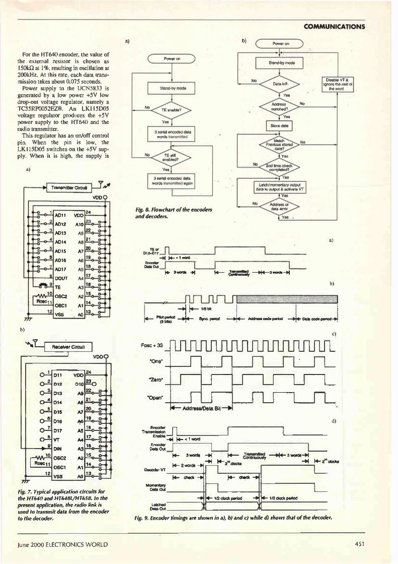
COMMUNICATIONS
For the HT640 encoder, the value of the external resistor is chosen as 1501d1 at 1%, resulting in oscillation at 200kHz. At this rate, each data trans-mission takes about 0.075 seconds. Power supply to the UCN5833 is
generated by a low power +5V low drop-out voltage regulator. namely a TC55RP0052EZB. An LK I 15D05 voltage regulator produces the +5V power supply to the HT640 and the radio transmitter. This regulator has an on/off control
pin. When the pin is low, the LKII5D05 switches on the +5V sup-ply. When it is high. the supply is
Transmitter Circuit Twe VDD
0--0 0-0
0-0 re--0 •-0
• 0
mr_10
Rosci
2
777
AD11 VOD
AD12 A10
AD13 A9
AD14 A8
AD15 A7
AD18 A6
AD17 AS
DOUT A4
TE A3
OSC2 A2
OSC1 A
VSS AO
24
23 o-• o •
22 o-O—•
21 o-•
20o
0—•—•
13-41 o--•
19 0.-• o •
18 0-* o•—•
17 o-• o—•
16 o-41 o •
15 o•-•
14 o-• 0--•
13 0—
Receiver Circuit
o
VDD
0-2
0--
0 _1
5
7 0 --
8 o-
Roc11
12
777
011 VDO
ID12 010
013 A9
014 A8
015 A7
D16 A6
017 AS
VT A4
DIN A.3
OSC2 A2
OSC1 Al
VSS AO
24
23 „
22 0-•
21 o-• 0--•
20 0-41 O0 •
19 o-• 0 •
18 0-•
Fig. 7. Typical application circuits for
the HT640 and HT648L/HT658. In the
present application, the radio link is
used to transmit data from the encoder
to the decoder.
17 o-• o—•
18 o-•
15o 0-• o--•
14o o--• -101
4- 2 words -01 2 clocks • Decoder VT
13 0-. o 4- check -0i o
momentary Data Out
Latched Data Out
a) b) C
Power on
Stand-by mode
TE enable',
3 serial encoded data
words transmitted
TE still enabled',
Yes
3 serial encoded data
words transmitted again
Fig. 8. Flowchart of the encoders
and decoders.
TE D12-017
_bi .‘ word
Encode 1 Data Out _I
No
Power on
Stand-by mode
Data in?
Address
matched?
Store data
Match Previous stored
data'
2nd time check completed',
Yes
o
Latch/momentary output data to output & activate VT
i Yes
Address or data error
Yes .
a
14- 3*pda 9.1 14-
-4"
mil_ Pilot penal _0;4_ (6 brts)
Transrneled Contnuousty
Disable VT 8. ignore the rest of
the word
I»
—Lit LI
Fosc - 33
One
'Zero'
'Open'
ft3 [Mt
Sync penod 4 Address code peood - le...1- Data code pendd
4— Address/Data Bd
Encode 11_ Transmission
Enable _401 14_ < 1 word
Encoder Data Out
14- 3 words HSI 14— jenunsminesd,y —044- 3 words - $
- fei F.- 2" doom
N-
-01 41- 1/2 clock period -1014- 1/2 clock pertod
Fig. 9. Encoder timings are shown in a), b) and c) while d) shows that of the decoder.
June 2000 ELECTRONICS WORLD 451

COMMUNICATIONS
LOGIC SUPPLY
SERIAL DATA IN
POWER GND
STROBE
OUTI
OUT2
OUT3
OUT4
OUTS
OUT6
OUT7
OUT8
OUT9
OUTIO
OUT11
OUT12
OUT13
OUT14
OUT15
OUT16
Fig. 11. Timing sequence of the serial data latch.
Three input lines — Data in, Clock
and Strobe — are required to
control data latch into the IC.
Fig. 12. Circuit
diagram of the
transmitter unit. The
serial data latch is used
as a computer
interface and HT640 is the encoder. The transmitter,
TX2, connects to the RS232 port of a
computer. It is also
possible to connect it to a computer's parallel port.
Connector( to
Pprt !unstop
D 1YW connector
To &II (0713)
To pen 7 (RIS)
To PIn 3 ITD)
To purS GNDI
Pins on the
RS232 port
Ond
a, Pin out
DATA IN
CLOCK
STROBE
OUTPUT ENABLE
OUT
CLOCK
SERIAL DATA OUT
OUTPUT ENABLE
OUT32
OUT31
OUT30
OUT29
OUT28
OUT27
OUT26
OUT25
OUT24
OUT23
OUT22
OUT21
OUT20
OUT19
OUT18
OUT17
LOGIC GND
Load data bit into shift register
CLOCK
SERIAL DATA IN
STROBE
OUTPUT ENABLE
Fig. 10. Pin-out, internal block
diagram and output stage of the
UCN5833A serial data latch.
Load data to outputs
RI-R3 41,7
o o DATA
STROBE o o
+5Y
C3
100nF I
C7.C8 ICOp
38
2
4
7rKle C7 C8
Vos EN
I(
DATA
SV
OFF ON
OR/OFF
ONO
D1-03 SOI Zone
*ØI ssell& ad paper Low swab& on p—
CS U(115050
V-J5
2
0—
o
o
o
o
35
34
33
32
31
OS
61 V•
LED2
LC LED
4S7 816
Our
0012
OUT3
OUT.
OUTS
OUTS
OuT7
OUT8
OUT9
OuTIO
°U.", OUT11
05111 00712
OuTIO OUT13
00129 CUTI
OUT28 CUTIS
00127 ours
OUT26 OUTI7
OUT25 00116
OUT19
Turn off transistor
I I
RLI
13
14
IS
17
18
19
12 20
13 21
14 22
612
15 23
8
2
8 3
19 4
20
— 6
4
RL3 UCN5833A
Pull-up ...mops tot outputs ot UCN58.13
OUTIOuT8 are pused up to 2nd .5v so RL I la,
OUT5I-OUT16 ant pulled up to 2nd •SLI by RU. 146
OUT17.0UT24 peed up to 2nd •5+ by 613. 105
00125-OUT32 Oro puled up to V• by 614 101(
L__
2nd .5V
46-
24
VDO AO 0.
A
A4
AS
A6
Al
46
A
00 IC3
NT-640
01
02
03
04
05
06
07
TE Vs*
12
32-BIT SHIFT REGISTERS
OPEN COLLECTOR OUTPUTS
b. Internal block diagram
FROM INTERNAL
LATCHES
C, Output stage
CO
100nF
SERIAL DATA OUT
OUT
switched off. This scheme is adopted in order to save power when the trans-mitter is idle. In this mode, the current consumption of the board is around I.5mA.
Receiver circuit details Figure 13 is the receiver's circuit dia-gram. This module receives the trans-mitted radio signal from its helical antenna. Demodulated output is then fed into the decoder. For the decoder. the value of the external resistor is cho-sen as 140kfl at 1%, which gives an
t type &Isms
e CS
2the
SW
RF OUT
RF ONO
DATA IN
GND
Ul
TX2 Rode tranarnatst
modulo
ELECTRONICS WORLD June 2000 452

STRAP
.5V
Helical type antenna
RF IN
RF GND
CD
ONO
AF OUT
DATA OUT
LI I
5%2 433MHz
radio receiver
module
6
C3
100nF
9
10
RI
140k
e
•
23 2 3 4 e 7
62 10k
OSC1 2
DATA IN
VT DO DI 02 D3 DO D1 D2 03
ICI HT.648U658
ND
AO Al 42 43 44 45 AS A7 48 A9
VCC
13 la 15 16
•
17 18 19 20 21
63 10k
22
AO
ON- O ON
OFFal oFF
AI
1:1
48 43 A4 AS AS Al AS A9
SW1
ackinkes soled«
Fig. 13. Circuit diagram of the receiver unit. RX2 is the radio receiver and the HT648L or HT658 is the decoder. HT648L gives a latched output and HT658 gives a momentary output.
oscillation frequency of 200kHz. The address of the decoder is set by a
10-way dip switch. Outputs from the decoder and VT line are available from .13. A low-power, low drop-out voltage regulator, the TC55RP0052EZB, pro-duces +5V power supply.
Programming Operation of the transmitter is con-trolled by the DTR, RTS and TD lines of the RS232 port. Data bits to be load-ed are put onto the RTS line and are shifted into the shift register of the UCN5833 at the low-to-high transition of DTR, connected to the clock line. After 32 clocks, 32 bits are loaded
into shift registers. Next a low-to-high-then-low pulse is applied to the TD line, connected to the Strobe line, to latch the data to the outputs OUT! to OUT 32. In idle mode - i.e. with the transmit-
ter not transmitting any data - OUT25 is at logic high to switch off power supply to the encoder and radio trans-mitter to save power. A data transmis-sion comprises the following proce-dure.
Firstly, OUT I to OUTIO are loaded with address bits; OUT11 to OUT18 are loaded with data; OUTI9 is loaded with '1' to enable the TE line. Next, OUT25 becomes low for 0.2
second. During this period, the HT640 and the radio transmitters are activated to transmit the encoded data. After this, OUT25 is brought high again to stop data transmission and to enter power save mode again. A demonstration program has been
developed for testing the functionality of the system using the Visual Basic 5 language. This language is supplied with a serial port control called 'MSCOMM' that is used to control all operations of the serial port.
In the VB5 editor, if the name of the MSCOMM control is declared as 'MSCOMM1', the following com-mands can be used to control the logic status of the DTR, RTS and ID lines. For details of the MSCOMM control, have a look at reference 4. To make DTR line high or low, use:
MSCOMM1.DTREnabled=True
or MSCOMM1.DTREnabled=False
To make RTS line high or low, use:
mSComml .RTSEnabled=True or MSCOMMl.RTSEnabled=False
To cause TD line to generate a low-to-high-then-low pulse, use:
MSCOMM1. Output= " 0 "
4
SW
Gnd .12V
J3
.5V
Val.'s] Transmission (VT,
O DB7
-o DB6
O DB5
o DB4
O 063
0 DB2
O DB1
o DBO
Ground
Ground
1 2 3 4 5
6 7 8 9 (a) 9-pin male socket viewed from the back of the computer
1 2 3 4 5 6 7 8 9 10 11 12 13
14 15 16 17 18 19 20 21 22 23 24 25
(b) 25-pin male socket viewed from the back of the computer
Pin functions of the RS232 connectors 25 pin 9 pin Name Direction Description
(for PCs)
1 Prot 2 3 TO Output 3 2 RD Input 4 7 RTS Output 5 8 CTS Input 6 6 DSR Input
7 5 GND
8 1 DCD Input
20 4 DTR Output 22 9 RI Input 23 DSRD I /0
5V
64
4k7
LC LED
Protective ground Transmit data Receive data Request to send Clear to send Data set ready Signal ground (common)
Data carrier detect Data terminal ready Ring indicator Data signal rate detector
Fig. 14. Pins and functions of the RS232 port. In this design, TO, DTR and RTS lines control data loading into the serial-data latch. The COM port bit rate should be set to 9600 baud, 8 data bits, 1 stop bit and no parity bit.
June 2000 ELECTRONICS WORLD 453

COMMUNICATIONS
Rai Forml
Radio Digital Data transmission 1024 addresses, 8-bit data
Send byte to a receiver
Address (0-1023) FC"---
D ata (0-255)
Send data
Output square wave
Interval (>500ms] ¡50111
Start testing I Stop I
Exit ¡I
Fig. 15. User screen of the demonstration software, which allows you to send an 8-bit data word to a receiver specified by the address. If the 'Start testing' button is clicked, a square wave signal will be produced at the outputs of the specified receiver unit. The periods of logic high and low are determined by the value of 'Interval'.
Examples of how to use 'MSCOMM' control are given in List 1. The user's screen of the demonstra-
tion software is shown in Fig. 15. From that screen, the user specifies an address and a data byte to be sent. Clicking 'Send data' causes the trans-mitter to transmit the data to the speci-fied receiver. If the 'Start testing' but-ton is pressed the specified receiver outputs a square wave signal. The peri-ods of high and low state are deter-mined by the interval — which is a value bigger than 500ms. Click 'Stop' to stop testing.
Application ideas In a remote control application, the eight digital outputs from the receiver could control lights, heaters, motors, etc., using mechanical or solid-state relays.
In an information distribution or mes-sage display system, it would be possi-ble to send a message to particular groups of receivers with their own dis-
play units. Because of the addressing capability, it would also be possible to set up a form of paging system. Finally, I would like to thank Mr
Kangyan from Radiometrix Ltd for his help with this design. 11
References I. Data sheets for TX2 and RX2 are
available from Radiometrix Ltd. Tel: + 44 (0) 20 8428 1220. Web site: www.radiometrix.co.uk
2. Data sheets for HT640, HT648L and HT658 are available from Holtek. Web site: www.holtek.com.iw
3. PC Interfacing — Using Centronic, RS232 and game ports, Pei An, Newnes, Butterworth-Heinemann, 1998, ISBN0240514483.
4. Real-world programming with Visual Basic, Anthony T. Mann, SAMS publishing, 1995, ISBN0672306190.
List 1. Demonstration program for the wireless RS232 link in Visual Basic. Function loaddata_1(dataA As Byte. dataB As Byte. dataC As Byte. dateD As Byte) 'Load 4 byte. (8 bite) into the UCNXX 'DTR = clock. CTS = data, TX = strobe 'if UCN5833/32 is used: RTS.true, output low (transis-tor on). .RTS=falee, output high (tranaistor off) Dim i As Byte 'load Port D For i = 1 To 8
NSComml.RTSEnable . 1 - (data)) And bitweight(9 - i)) O bitweight(9 - i) NSComml.DTREnable = True NSComml.DTREnable • False
Next i 'load Port C
For i 1 To 8 NSComml.RTSEnable = 1 - (dataC And bitweight(9 - ill
O bitweight(9 - i) NSComml.DTREnable . True NSComml.DTREnable . False
Next i 'load Port El For i = 1 To 8 MSComml.RTSEnable = 1 - (dataB And bitweight(9 - i))
\ bitweight19 - i) NSComml.DTREnable True NSComml.DTREnable . False
Next i 'load Port A For i = 1 To 8
MSComml.RTSEnable = 1 - (dataA And bitweight(9 - i)) O bitweight(9 -
MSComml.DTREnable . True MSComml.DTREnable = False
Next i 'Strobe data into UCN serial latch IC
Sleep (20) NSComml.Output = .0 .
End Function
Function loaddata_2(I Dim outbuf(1) As Byte 'Load 32 bytes into UCNXX outbuf(1) = 255 For i = 1 To 32
NSComml.RTSEnable . 1 - DataBits(33 - i) NSComml.DTREnable = True MSComml.DTREnable . False
Next i
Sleep (20) NSComml.Output • outbuf End Function
Function save_poweri) Dim outbufil) As Byte 'Load 32 byte. into UCNXX outbuf(1) = 255 For i • I To 32 MSComml.RTSEnable . 0 MSComml.DTREnable . True NSComml.DTREnable = False
Next i
Sleep (20)
MSComml.Output • outbuf End Function
Private Sub Commandl_Clicki) Dim Addressmab As Byte, Addresslab As Byte, i As Byte .UCN5833, Outl to Outil . address bits 'UCN5833, Outll to 18 . data bits
'UCN5833. Out19 = Transmit enabled 'UCN5833, Out25 = power ON
'Control of MT640 (4 steps): ' Load data into UCN5833 ' Power ON ' Enabled TE ' Disable TE
..0 to switch off power to the redi , transmitter
Timerl.Interval Val(Text3.Text) If Timerl.Interval < 300 Then Timerl.Interval = 300
Text3.Text = Timerl.Interval Timerl.Enabled = True End Sub
Private Sub Command4_Click()
Timerl.Enabled = Pelee End Sub
Private Sub Form_Load() Com_number Do
Addressmab Val(Textl.Text) \ 256 Com_number (InputBox5( .Input 1,2.3 or 4 to select. ,
Addresalab VallTextl.Text) - Addresamsb Chr(13) & COM1, CON2.COM3 or CON4 -. • . For i = 1 To 8 port . ))
DataBita(i) = (Addresslsb And bitweight(i)) \ If Com_number Then End bitweight(i) Com_number Val(Com_number) Next i Loop Until Com_number os0
DataBite(9) (Addressmsb And bitweight(1)1 \ NScomml.commPort = Com_number bitweight(1) NSComml.OutBufferSire = 1 DataBite(10) (Addresemeb And bitweight(21) O NSComml.InputMode = comInputNodeBinary bitweight(2) NSComml.DTREnable = False For i . 1 To 8 NSComml.PortOpen = True
Dotal/tell° • i) = (Val(Text2.Text) And bitweight(i)) bitweight(1) . 1: bitweight(2) = 2: bitweight(3) . 4: O bitweight(i) bitweight(4) = 8:
Next i bitweight(5) = 16: bitweight(6) = 32: bitweight(7) to_transmit 1 .to transmit 64: bitweight(8) = 128: power_on . 1 'to power on End Sub DataBit.(19) = to_transmit '.1 to enable TE. =0 to dis-able TE
DataBite(25) = 1 - power_on '.1 to power the radio transmitter
..0 to switch off power to the radio transmitter dummy = loaddata_2 Sleep (200) 'a short delay for sending the data (18 bit.) save_power End Sub
Private Sub Command2_Click() MSComml.PortOpen False End End Sub
Private Sub Command3_Click() done . robe
Addresamsb = Vel(Textl.Text) 0 256
Addre681»b = Velnextl.Text) - Addremsumb For i = 1 To 8
DataBite(i) (Addreaslab And bitweight(i)) \ bitweight(i) Next i
DataBits(9) (Addressmsb And bitweight(1)) bitweight(1) DataBite(10) = (Addresemsb And bitweight(2)) bitweight(2) For i • 1 To 8
DataBite(10 • i) = 1 Next i to_transmit = 1 'to transmit power_on . 1 'to power on DataBit.(19) to_transmit ..1 to enable TE, .0 to dis-able TE
DataBits(25) . 1 - power_on '=1 to power the radio transmitter
Private Sub Timerl_Timer() Dim i As Byte For i = 1 To 8
DataBits(10 • i) = 1 - DataBita(1Q o i) Next i
to_transmit = 1 - to_transmit power_on = 1 - power_on DetaBite(191 = to_transmit ..1 to enable TE, .0 to dis able TE DetaBite(25) = 1 - power_on ..1 to power the cadi: transmitter
..0 to switch off power to the radio transmitter dummy = loaddata_2 Sleep (200) save_power
End Sub
List 2. Module1.bas. . bitweight(8) As Byte
.,_obal done As Boolean Global dataA As Byte, dataB As Byte. dataC As Byte. date] As Byte Global DataBit.(32) As Byte Global Com_number A. Variant Declare Sub Sleep Lib .kerne132. (ByVal dwMilliseconds As Long)
454 ELECTRONICS WORLD June 2000

_
ELECTRONICS Subscribe for 3 years, pay for just 2 .MM-.P

YErEieRlilit4Zel; Please enter my subscription for:
(tick one of the following)
UK Europe Rest of World
3 years (36 issues) £72 E £103 £123 ai F REE!
1 year (12 issues) E £36 E £51 E £61
Detailed circuit diagrams
New product news
Informative design-oriented explanations
CAE software
If you're not completely satisfied with Electronics World within
the first 60 days we'll refund your money in full - no questions asked.
Please allow 28 days for delivery of your first issue.
Please tick here if you do not wish to receive direct marketing promotions from other
relevant companies.
fhree ways to pay 1 enclose a cheque for E made payable to Electronics World.
Please charge my Visa/Mastercard/American Express/Diners
Club/Switch/Delta (please delete os appropriate)
Card Number
I
Expiry date -11I/
Signed
Valid from
(SwitchiDe/ta only)
Date
Issue no
Please invoice me/my company. Purchase Order No.
Name
Job Title
Company
Address
Tel. No. Fax No.
E-mail address
Company VAT registration number
Return your completed form to: Electronics World Subscriptions, FREEPOST RCC 2619, PO Box 302, HAYWARDS HEATH, UK, RH16 3BR Fax: +44 (0)1444 445447 E-mail: [email protected]
122
Tel: +44 (0)1444 475662

Cer • 0I. • •
sample pack - sponsored by Greenway Electronics Products - on the cover of this issue comprises four pairs of ceramic stand-off bushes specifically designed to lift hot components such as power resistors off the PCB. The ceramic they are made from is a high-temperature
insulator with a low coefficient of expansion. The material is Steatite ceramic C220 conforming to DIN VDE 0335 and IEC 672-3. Non toxic, it has good mechanical properties i.e. resistance to bending, and high corrosion resistance and resistance to abrasion. These bushes can be used individually or can be
stacked. Types are also available with interlocking 'fish-spines' (218-001 and 218-003) that lend themselves to applications where stacking is involved. In addition to being used as stand-offs, these bushes
can be threaded onto heating elements or hot wires to provide a flexible high-temperature insulator. For special applications, Greenway can supply
customised parts. To order more bushes, or to obtain details of Greeenway's range of products and services, fax 0208 643 0440, e-mail [email protected] or write to Greenway at 128-130 Carshalton Road, Sutton,: Surrey SMI 4TIN.
Visit Greenway's web site at www.greenway-ltd.co.uk
D2
Bush dimensions - contact Greenway for
details of the range of sizes available.
Part number
218-001
218-003
219-001
219-002
1
1
2
1.3
02
3 3
4
4.5
3
5
6
8
Radiometrix Ltd
868MHz band Transmitters & Receivers
Transmitter— TX3 • Crystal-locked PLL, FM
modulated at up to 50 kbps
• Operation from 2.2V to 10V @ 10mA
• Built-in regulator for improved stability and supply noise rejection
• OdBm (lmW) RF output
Receiver- RX3 • Single conversion FM
superhet with SAW front end filter
• Operation from 2.7V to I3V @ 9.5mA
• Built-in regulator for improved stability and supply noise rejection
• 50kb/s, -100dBm sensitivity @ 1ppm BER
• RSSI output with 75dB range
The TX3 and RX3 are miniature UHF radio transmitter & receiver modules designed for PCB mounting. They allow the simple implementation of data links at speeds up to 50kbps and distances up to 30m in-building or 120m over open ground.
Universal Evaluation Kit
This evaluation system can be used to evaluate a TX1 or TX2 or TX3 transmitter module together with snatching RX1 or RX2 or RX3 receiver or a BiM ¡nodule.
www.radiometrix.co.uk
Range offacilities • Range & Target
Environment Testing
• Interference Identification
• Antenna Evaluation
• Transient Analysis
• Communication Eye Diagram
• Linking external hardware directly or via on board Radio Packet Controller
Contact: Radiometrix Ltd 4 Hartcran House Gibbs Couch Watford WD1 5EZ England Tel: -1-44 (0)20 8428 1220 Fax: +44 (0)20 8428 1221
CIRCLE NO.110 ON REPLY CARD
June 2000 ELECTRONICS WORLD 455

IDEAS Fact: most circuit ideas sent to Electronics World get published The best circuit ideas are ones that save time or money, or stimulate the thought process. This includes the odd solution looking for a problem — provided it has a degree of ingenuity. Your submissions are ¡udged mainly on their originality and usefulness. Interesting
modifications to existing circuits are strong contenders too — provided that you clearly acknowledge the circuit you have modified. Never send us anything that you believe has been published before though. Don't forget to say why you think your idea is worthy. Clear hand-written notes on paper are a minimum requirement: disks with separate drawing
and text files in a popular form are best — but please label the disk clearly.
Two transistor FM broadcast receiver "T his simple FM radio receiver uses only two I transistors. They function as a low-power oscillator,
+3V
10k
(D98)
C2 200n
1—e. Audio
BF797
L: 4118SWG on 4mm air core
Cl: 2 - 14pF trimmer
This synchronised oscillator recovers the audio from a broadcast FM station.
the frequency being determined by L and C1. When the frequency of oscillation is the same as that of
the wanted signal, the recovered audio is available at the output. The audio signal is dc blocked by C2 and fed to an audio amplifier. Ra¡ik Gorland D98
This circuit was so intriguing that we had to see if it worked. It does. Thanks to Ian Hickman for trying it out. Ed.
Winner of the second National Instruments digital multimeter worth over £500
V2
=Asincot
\I =Asin(cot+8)
5k i 1On
5,7
Simple phase-sensitive detector +15 (C40) -r11c XRL3600 is a
transconductance op-amp with linearising diodes and buffer, similar
+15 to the LM13600. It can be used as a modulator or audio range mixer. Here, it is shown connected as a
phase detector, the output being proportional to I/2cos8. The
Out -cosS
This phase-sensitive detector can be 510 used as a modulator or audio-range
mixer and, having only one op-amp, —15 it is easy to implement.
advantage of using this device is its simplicity, since the CR low-pass filter to suppress the carrier frequency ripple and its harmonics can be added 'inside' the op-amp, so that no other op-amp is needed. The cut-off frequency too of the low-pass filter is wo= Vim-, where wo should be much less than 2w, the frequency of the input signals. Kamil Kraus Rokycany Czech Republic C40
456 ELECTRONICS WORLD June 2000

( National Instruments sponsors Circuit Ideas
National Instruments is awarding over £3500 worth of equipment for the best circuit ideas.
Once every two months throughout 2000,
National Instruments is awarding an
NI4050 digital multimeter worth over
£500 each for the best circuit idea
published over each two-month period. At
the end of the 12 months, National is
awarding a LabVIEW package worth over
£700 to the best circuit idea of the year.*
About National Instruments National Instruments offers hundreds of software and hardware products for data acquisition and control, data analysis, and presentation. By utilising industry-standard
computers, our virtual instrument products empower users in a wide variety of industries to easily automate their test. measurement, and industrial processes at a fraction of the cost of traditional approaches.
Software Our company is best known for our innovative software products. The National Instruments charter is to offer a software solution for every application, ranging from very simple to very sophisticated. We also span the needs of users.
from advanced research to development, production. and service. Our flagship Lab VIEW product, with its revolutionary, patented graphical programming technology, continues to be an industry leader. Additional software products, such as LabWindows/CVI, Component Works.
Measure and VirtualBench, are chosen by users who prefer C programming, Visual Basic. Excel spreadsheets, and no programming at all, respectively.
Hardware Our soft are products are complemented by our broad
selection of hardware to connect computers to real-world signals and devices. We manufacture data acquisition hardware for portable, notebook, desktop, and industrial computers. These products, when combined with our software, can directly replace a wide variety of traditional instruments at a fraction of the cost. In 1996 we expanded our high-performance E Series product line in PCI. ISA and PCMCIA form factors, shipped our first VXI data acquisition products, and added remote (long-distance) capabilities to our SCXI signal conditioning and data acquisition product line. Our virtual instrumentation vision keeps us at the forefront
of computer and instrumentation technology. National Instruments staff works actively with industry to promote international technological standards such as IEEE 488, PCMCIA, PCI. VXI plug&play, Windows 95/NT, and the Internet. More importantly, we integrate these technologies into innovative new products for our users.
•All published circuit ideas that are not eligible for the prizes detailed here will earn their authors o minimum of £35 and up to £100.
NI4050 The NI 4050 is a full-feature digital multimeter (DMM) for hand-held and
notebook computers with a Type II PC Card (PCMCIA) slot. The NI 4050
features accurate 51/2 digit DC voltage. true-rms AC voltage, and resistance
(ohms) measurements. Its size, weight, and low power consumption make it
ideal for portable measurements and data logging with hand-held and notebook
computers.
• DC Measurements: 20mV to 250V DC; 20mA to 10A
• AC Measurements: 20mV rms to 250V rms; 20tnA nits to 10A nus;
• True rms, 20Hz to 25kHz
• Up to 60 readings/s
• UL Listed
• 5112 Digit Multimeter for PCMCIA
Lab VIEW LabVIEW is a highly
productive graphical
programming environment
that combines easy-to-use
graphical development with
the flexibility of a powerful
programming language. It
offers an intuitive
environment, tightly
integrated with measurement
hardware, for engineers and
scientists to quickly produce
solutions for data acquisition,
data analysis, and data
presentation.
• Graphical programming development environment
• Rapid application development
• Seamless integration with DAQ, GPIB, RS-232, and VXI
• Full, open network connectivity
• Built-in display and file I/O
National Instruments — computer-based measurement and automation National Instruments, 11 Kingfisher Court, H‘unbridge Road, Netsbury, Berkshire, RG14 551. Tel (01635 523545), Fax (01635) 52439.i
info.uligniconi www.ni.com.
June 2000 ELECTRONICS WORLD 457

CIRCUIT IDEAS
cl 10µ
R1 Tr,
KL303E (C56)
This beeper/blinker operates using a
simulated injection field transistor.
Two-transistor AV alert Asimple audio-visual alerting circuit is
described here. Such a circuit can be arranged using an
injection field transistor, but these are no longer common items. Instead, the 'beeper' shown emulates an injection field transistor with the combination of an n-channel FET and a p-n-p transistor. These provide a current-voltage characteristic with a nega-tive dynamic resistance. Switching on the beeper generates short synchronous sound and light signals.
Working in conjunction with C2, the value of R1 determines the duration of the sounds; R2 defines the pause between them. Capacitor C2 provides the characteristic
colouring or the sound. The circuit uses a 40S-1 low resistance phone. At a supply voltage of 6 to 15V, average current con-sumption is 1.5mA. Mickael Shustov Tomsk
Russia
C56
TO LAMPS
P0102D 400V 800mA SCR
Frugal flasher Two transistors and an SCR form a reliable replacement to thermally-I activated switches used for lamp-flashing. Unlike many similar
circuits, this one needs no high-power resistors or high-voltage capacitors. Timing is provided by loan and lkû resistors with a capacitor. Best
performance is obtained with a capacitor from 470 to 1000µF and with the resistor over the emitter and collector of BC327 set at around 12k.Q. For proper operation it is essential to use an SCR with a very sensitive
gate. If you are unable to find one, you can use triacs such as the TIC206M rated at 600V, 4A. Note that you will still need the diode bridge. Flavio Dellepiane Genoa Italy
(C57I
Multichannel amplitude discriminator
Amplitude discriminators are used in engineering measurement systems,
to route signals into separate channels, on the basis of amplitude. The amplitude of a signal is easily enough indicated by multi-comparator chips driving LEDs, such as the UAA170/180, UL1970N/80N, A277DI etc.
£50 Winneri
A 3 x Ge 21.,2 nevo
6V2
100n
• 10k 2 x Si • •
2k
10k
2k
15k*
47k 4_
The circuit shown uses a UAA180 to direct a signal to one or other of several separate outputs, depending upon its amplitude. The input is connected to the inputs
of twelve CMOS analog switches, and also to a voltage doubler type rectifier circuit. Resultant dc level is smoothed
DAI
/ / / / / /
UAA180
100n
INPUT 1-4
12
2
\
/2
2 x CD4049
13
2
01 > U2
3 x CD4066
, 12
12
12 x LED
10
12 x 1k
This circuit directs
a signal to one of
several outputs,
according to its
amplitude.
U12
+r
by an electrolytic capacitor and applied to pin 2 of the UAA180. Upper and lower limits of the 12-step
indication range are set by potentiometers connected to pins 3 and 16 of the device, the drop across two silicon diodes setting the minimum range which can be set. The UAA180 indicates the level of
the signal present by lighting the appropriate LED. Via one section of two hex inverters, it also closes one of the analogue switch sections, routeing the input signal to the corresponding output channel.
In addition, the device can form the basis of a multichannel analogue quasi-filter, by introducing a frequency-to-voltage converter'. By summing the output signals via controlled dividers you can synthesise a multiband equaliser, to realise a rejecter circuit, bandpass or other filter. Mickael Shustov Tomsk
Russia
C57
Reference I. Shustov M. A. Application of
polycomparator chips in engineering of
radio communications,' Radioamateur
(Byelorussia), 1997 No 6 pp. 13-15.
458 ELECTRONICS WORLD June 2000

CIRCUIT IDEAS
Alternative neon tester t is important that )ou read the I warning panel on the right before going any further. This idea is an alternative to the
traditional screwdriver mains tester incorporating a miniature neon indicator in its handle. It uses a complementary pair of transistors connected as a multivibrator. When the 510k probe touches a
220V live line, a current not exceeding 400pA charges the capacitors via the bridge rectifier, returning through the user (sensor). The device then begins to generate short flashes of light and sound impulses (clicks), at a frequency of up to five per second. Using high-frequency diodes and
an antenna, connected instead of the 510k12 probe, the device is capable
of remotely registering the presence of high-frequency fields of high strength, e.g. fields of transmitters, horizontal sweep transformers, etc. • Mickael Shustov Tomsk Russia C55
(C55)
Phase 510k
Warning Do not use this circuit as prescribed here by its author, i.e. do not use the circuit t test the mains or any other potentiall lethal voltage source. The idea is fine, but the circuit is n
isolated. If the 510ka resistor fails, t c ircuit immediately becomes lethal if on mains and high voltages. Ed.
U
•„ poi LED
250n
401
•
1M6
Alternating voltage tester with audible and visible indication.
1k2
Tr,
NPN
Ten year index new update
nooks ircurt Ideas Hard copies and floppy-disk databases
both available Whether as a PC data base or as hard copy, SoftCopy can supply a complete index of Electronics World articles going back over the past nine years.
The computerised index of Electronics World magazine covers the nine years from 1988 to 1996, volumes 94 to 102 inclusive and is available now. It contains almost 2000 references to articles. circuit ideas and applications - including a synopsis for each.
The EW index data base is easy to use and very fast. It runs on any IBM or compatible PC with 512K ram and a hard disk.
The disk-based index price is still only £20 inclusive. Please specify whether you need 525m, 3.5in DD or 3.5in HD format. Existing users can obtain an upgrade for £15 by quoting their serial number with their order.
hoto copies of Electronics World articles from bac ssues are available at a flat rate of £3.50 per rticle, £1 per circuit idea, excluding postage.
ard copy Electronics World index ndexes on paper for volumes 100,101, and 102 re available at £2 each, excluding postage.
TABLE OF CONTENTS
Applications Applications by description Applications by part numbers Com an add
nformation
sbiect Inde. Analogue Design Audio Arionic s Broadcast Communications Components Computing Consumer Electronics Control Electronics Digital & OSP Design
History _
The Electronics World SoltIndex runs from January 19E6 to May 19% and contains references to 1300 articles and BCC circuit ideas There is a separate author index with full cross references Reprints can be obtained for all the articles in this index • see the Information section for more details For up to date information about Electronics World See Our websde at http //ww« softcopy co uk
www.softcoey.co".uk Ordering details
The EW index data base price of £20 includes UK postage and VAT. Add an extra £1 for overseas EC orders or £5 for non-EC overseas orders Postal charges on hard copy indexes and on photocopies are 50p UK, £1 for the rest of the EC or £2 worldwide. For enquires about photocopies etc please send an sae to SoftCopy Ltd. Send your orders to SoftCopy Ltd, 1 Vineries Close, Cheltenham G1.53 ONU. Cheques payable to SoftCopy Ltd, please allow 28 days for delivery.
e-mail at SoftCopyecompuserve.com, tel 01242 241455
June 2000 ELECTRONICS WORLD 459

CONTROL ELECTRONICS
Efficient battery power supplies
Fig. 1. Switched mode power supply
used in the tanti meter. For clarity
the shutdown timer and low-battery
indicator have been removed. In this
article, circuit performance is
studied using three different capacitor
combinations for C1, C2 and C3.
Using the battery-powered regulator he designed for his tard Cyril Bateman demonstrates how important subtle capacitor parameters are in gaining maximum efficiency.
The ever increasing demand for small, lightweight and efficient battery powered equipment has
resulted in an explosion in the number and variety of dedicated power supply integrated circuits. Many of the latest and most efficient designs are only available in minute surface mount packages. These encourage designers to use physically small capacitors and inductors, which can have high losses. Portable equipment that doesn't need a lot of current can be provided with a stabilised +5V, or lower, rail using only a low drop-out linear regulator, a decoupling capacitor and a PP3 battery. If required, a negative supply can be produced using a charge-pump con-verter. Provided the required current is
small, this combination provides a low noise, low first-cost system and accept-able battery life. However, the con-ventional alkaline PP3 size battery, typ-ically rated at 550mAh, exhausts very quickly when providing the 50mA that may be needed to support an efficient ±5V supply at 20mA.
Batt •
Batt -
v
Switching alternatives With increasing load current, battery life using a linear regulation system becomes unacceptable, and a switched-mode alternative becomes essential. While new battery technologies are
now available, many designers choose to use AA-sized alkaline cells when their load cannot be supplied using a PP3 type. To ensure acceptable battery life with a 5V supply, four such cells may be needed in series. Generating a +5V stabilised supply
from four AA batteries poses the diffi-culty that with fresh batteries, the cir-cuit must reduce the battery voltage. As the batteries discharge, the circuit must automatically change over to boosting the battery voltage. Capable of very high efficiency, the
switching process takes current from the battery supply in bursts. Batteries possess internal resistance, so these current pulses impose fast transients on the supply voltage and result in signif-icant output noise levels. These tran-sients may be minimised by choosing the capacitors and inductors carefully.
Cl F 220uF
111,
RS 100K
LaH
Ulm LBO
SHDN
LTI303CN8 FB
SONO POND
Ul
2112
DI
Z1578813
.C2
meter,
There's more on this in the panel enti-tled, 'Batteries'. I experienced this problem first hand
when designing the +5V switched-mode power supply featured in my tana meter circuit'. In this design, the LT1303CN8 integrated circuit2 boosts the battery voltage just enough to enable the transistor linear regulator to provide the required +5V output. Using this circuit as an example, I
will demonstrate to you the change in transient voltage levels that I measured using different capacitors in the CI, C2 and C3 positions, Fig. 1. These mea-surements illustrate the importance of careful component selection. A switched-mode power supply
draws 'pulses' of current from the bat-tery. This intermittent current creates transient voltage drops due to the inter-nal resistance of the battery, the 'reversed battery' protection diode, the switch and circuit wiring. These momentary voltage drops generate sig-nificant noise, degrading power supply regulation and battery life, Fig. 2a). These current peaks can be min-
R2 300K
C3
, 5e0ur 2112
+5v
Cl
e e
—11-
1 00
0 v
Stabi I ised 5 vo I t supp I g
input T RR Batteries
460 ELECTRONICS WORLD June 2000

CONTROL ELECTRONICS
imised by using an input storage capac-itor, C1, adjacent to the switched-mode power supply integrated circuit. This reduces and smooths out the peaks of current demand, the battery then sup-plying a more steady current into this capacitor. Other capacitors are needed to act as
reservoir, C2, and perform smoothing, C3, following the power supply switch-ing rectifier and the linear regulator. Values and voltages required for
these capacitors depend on your chosen power supply integrated circuit. Most data sheets recommend makers' part numbers, as well as capacitance values and voltage rating. Unfortunately many of these specific devices are not easily obtained in the UK - especially in the smaller quantities needed for prototype development.
Effective capacitors For a +5V, 100mA output supply using 4 AA batteries, the LT1303 data rec-ommended capacitor types and values which were not immediately available. They suggested 33pF for C1 and C2 with 220pF for C3. For many years my stock capacitors
have been chosen from the Philips 037 sub-miniature general purpose type and the company's 135 low-impedance, high-ripple ranges3. The small capaci-tors needed for this power supply are not available in the 135 style.
A worked example Using 47g, 50V and 220pF, 10V Philips 037 radial-lead aluminium elec-trolytics, I assembled a prototype power supply. Powered from four AA batteries and using a 100f1 resistive dummy load, this prototype was noisy and inefficient. I redesigned the PCB to decouple the
noise input to a capacitor from its smoothed output, using four-terminal
track routeingsl. This revised PCB, together with its loon load, was used with three capacitor combinations, to provide the oscillograms and measured results used in this article. To avoid variations in battery performance, the circuit was powered from my bench supply, set to 4.5 volt. I chose this voltage for two reasons.
First it is the median usable voltage from four AA alkaline batteries. Combined with the small voltage dropped in the 'reversed battery' pro-tection diode, it ensures the power sup-ply works only in its 'boost' mode. Using two 47pF, 50V 037 capacitors
for CI and C2, with a 220pF, 10V 037 for C3, the supply drew 86mA. Output was 5.IV, giving 51mA into the 100f1 load. The circuit was noisy with exces-sive output ripple voltages. Fig. 2. In this series of plots, to ensure the
very fast transient spikes can be seen, the Y amplifier settings for C1, C2 and C3 differ, but were kept consistent with change of capacitor, by capacitor ref-erence. I used 200mV/cm for C1, 100mV/cm for C2 and 50mV/cm for C3. In each case my 250MHz oscillo-scope probes were switched to divide by 10. Switched to unity, most of this fast transient detail was missing. The LT1303 IC features 'burst-
mode' operation, adapting its switching speeds to suit circuit conditions. For each photo, the X time base was set to 5ps/cm. To obtain a stable trace for a photo-
graph, the actual sweep rate was slowed using the vernier control. Hence the trace speed was not con-trolled. The important point here is the change in peak transient and ripple voltages with change of capacitor. The Y scaling is consistent for each capac-itor number. I then replaced both 47pF 50V
capacitors with two more 220e, 10V
Table 1. Measured parameter values for one sample of each capacitor style only. Unit/parameter 10kHz 30kHz 100kHz 300kHz 1MHz 47pF/50V Philips 037 121 (LI) 1.151 1.05 ESR (S2) 1.106 1.043 Capacitance (pF) 58.3 42.6
220p F/10V Philips 037 121 (il) ESA (SI) Capacitance (pF)
220pF/10V Rubycon YXF IZI ((l) ESA ((I) Capacitance (pF)
0.824 0.818 129
0.404 0.394 153 94
0.785 0.783 68.4
0.372 0.372
0.993 0.94 22.6
0.738 0.74 27.1
0.341 0.34 44
0.938 0.93 7.87
0.706 0.71 9.1
0.322 0.32 20.7
0.878 0.87 1.99
0.671 0.67 2.0
0.308 0.32 9.2
037 types. The 47pF 50V and the 220pF 10V capacitor case sizes were 6.3mm by Ilmm.
Efficiency was slightly improved; the supply current measured 80.1mA. The LT1303 chip has changed mode, now producing three transient bursts per oscilloscope cycle. Using the same 'Y' oscilloscope settings for each capacitor reference as for Fig. 2, the transient
Fig. 2. Ripple waveforms together with superimposed fast transient voltage spikes, measured using Philips 037 capacitors. Capacitors C y and C2 were 47pF 50V with 220pF 10V for C3.
a) CI ripple voltage is 0.32V pk-pk, transient spikes are 1.14V pk-pk. b) C2 Ripple voltage is 0.36V pk-pk, transient spikes are 0.38V pk-pk. C) C3 Ripple voltage is 0.12V pk-pk, transient spikes are 0.25V pk-pk.
Fig. 3. With conditions set as for Fig. 2, these photos show the marginal improvement gained by substituting 220pF, 10V 037 capacitors for Cl and C2. Nominal capacitance is much increased, but ripple and transient spikes improve little. a) CI: Ripple voltage 0.26V pk-pk, transient spikes 1.02V pk-pk. b) C2: Ripple voltage 0.3V pk-pk, transient spikes 0.39V pk-pk. c) C3: Ripple voltage 0.1V pk-pk, transient spikes 0.235V pk-pk.
June 2000 ELECTRONICS WORLD 461

CONTROL ELECTRONICS
Fig. 4. Using three Rubycon YXF 220pF, 10V
capacitors, low impedance types
with the same physical size as
the 037. Although nominal
capacitances are unchanged from Fig. 2, the ripple
voltages are much smaller.
a) CI Ripple voltage is 0.12V pk-pk, transient spikes are 0.98V
pk-pk. b) C2 Ripple
voltage is 0.09V pk-pk, transient spikes are 0.36V
pk-pk. c) C3 Ripple
voltage is 0.035V pk-pk, transient spikes are 0.21V
pk-pk.
Fig. 5. Using Micropower
SwitcherCAD software from
Linear technology. Simply enter your chosen capacitor
into a dialogue box. The
schematic is automatically drawn then
simulated. The lower trace shows
that the voltage simulated at C2
approximates that measured, but the fast transients are
missing.
spikes and ripple voltages were little changed. With a nearly fivefold increase in nominal capacitance for Ci and C2, why had these waveforms not improved more? See Fig. 3. I removed these capacitors from the
printed board. After allowing sufficient time for them to cool to room temper-ature, I measured impedance at 100kHz. The 47µF capacitor measured 0.993Q, the 22011F slightly less at 0.738Q. Board area and height above board
being limited, the capacitor case size
could not be increased to tit the Sanyo 'Oscon' type 220g 10V size of lOrtun by Ilmm4. The Rubycon 220µF 10V YXF style case size was acceptable, and it claimed reduced impedance5. At 100kHz I measured 0.341Q
impedance, a notable reduction, so three of these types were fitted. My measurements were repeated, using exactly the same 'Y' settings as before, Fig. 4. Ripple voltage is substantially
reduced, but the transient spikes remain almost unchanged. Using the same PCB, components and set up, except for these three capacitors, current drawn from the supply had reduced to 75.6mA, improving efficiency. To reduce these very fast transients, I
inserted a 5111-1 inductor 4 and an addi-tional 220g, 10V YXF capacitor C4, as shown in the schematic. These reduced the transients and the ripple voltage to acceptable levels. The protection diode was removed
from circuit and a 5V supply applied. Now the current measured 66.5mA — representing an efficiency of 78%. I could now complete the design of the power supply for my tana meter. My curiosity had been aroused, so
when time permitted, I determined to retrace these steps in order to quantify why these differences occurred and write this article.
Capacitor parameters One extremely useful tool I used dur-ing the initial design phase of this power supply, was the Spice 2G based `Micropower SwitcherCAD' v2 soft-ware, available from Linear Technology2. This models the inte-grated circuit and provides a selection
61 11?1134 4xAA Alkaline to 5 1V at 51mA
1001 1N5817 Li DI
331tF C1
5 25-
5 20-
5 15/
51
of capacitors from its database. Other capacitors can be used provid-
ed you input values for ESR and capacitance. I suspect the ESR values used relate to a frequency of 100kHz and the capacitance is the catalogue value. I have not been able to confirm this from the help files or user manual, Fig. 5. This raises the question of whether,
in practice, ESR at 100kHz is the only relevant parameter? I believed other characteristics were equally important, but a study of capacitor makers' data did not help. While some makers provided full
data, it was not possible to discover how ESR at 100kHz had been mea-sured. It was not always clear whether quoted values were typical or maxi-mum values. Some capacitor makers provided no high frequency data at all, apart from a few selected impedance graphs. There's more on this in the panel entitled, 'Modelling Capacitors'. I decided to measure the 037 and
YXF capacitors using only general-purpose laboratory equipment and methods. While these were not preci-sion measurements, they gave an ade-quate comparison of ESR and capaci-tance/inductance and can be made without investing in extremely expen-sive, high frequency precision LCR meters, such as the Agilent Technologies HP4284. Using basic volt/amp impedance
measurement techniques, I measured samples of the three capacitors for impedance by frequency from 10kHz to 1MHz6. Then from phase measure-ments, I calculated ESR and capaci-tance at these frequencies. The accuracy of my impedance mea-
surements was confirmed simply by measurements of IQ and 0.047Q metal-film resistors. The true DC val-ues of these had been confirmed by measurement of voltage drop, while passing a direct current of 100mA. Values given in the tables for ESR
and capacitance however depend total-ly on the accuracy of my phase mea-surements. Using my phase meter6 with a 4.5-digit DMM for increased resolution of 0.01°, its accuracy for the angles measured is good up to 100kHz. As the capacitor approaches self-reso-nance and phase angles less than 1° must be measured, accuracy reduces. Philips' data for its 037 style is quite
clear, specifying a maximum IZI at 10kHz for both capacitance values, at 2.0Q The Rubycon YXF data available when I was developing the tana power supply simply claimed 0.412 at 100kHz for the 220i.iF, 10V capacitor. Current data from Rubycon clearly states that maximum impedance at 20°C is 0.4n, increasing to 1.6 Q at —10°C. The above
462 ELECTRONICS WORLD June 2000

CONTROL ELECTRONICS
measurements confirm both claims. From these calculated, apparent
capacitance values the similarity in my circuit's ripple and transient voltage performance between the 47e, 50V and the 220µF, 10V 037 types is explained. At 100kHz and higher, both capacitance values are similar. The 220g, 10V 037 capacitors I used offered 25% less impedance but little extra capacitance. The measured capacitance for the
Rubycon YXF style, reduces less with frequency. Across this frequency band its ESR is much smaller. Ignoring for now the very fast tran-
sient spikes, this increased capacitance coupled with its reduced ESR has more than halved the ripple voltage com-pared to that measured using the 220e, 10V 037 capacitors. The fast transient voltage spikes, less
than 5Ons duration, result from capaci-tor and circuit-board inductances. To evaluate whether this inductance is contributed by the 220tiF capacitors or by the circuit board, a different mea-surement is needed. I mounted both types as shunt loads to ground in test jigs. The), were inserted into a correct-ly terminated 5011 system. Application of a fast rise-time pulse
generator revealed these two capacitors exhibit dramatically different behaviour when subject to a fast rise time pulse. For Fig. 6a), both capacitors were mounted in individual, hut otherwise
Modelling capacitors ¡'he most problematic part in a switched mode power supply simulation is the capacitor model used. Because a switched-mode power supply operates essen-tially in the time domain, most designers will use a time-domain simulator, usually derived from the public-domain Spice series. As you have seen, capacitor
parameters are essentially frequency dependent. As a result, the simplistic ideal capacitor model provided in Spice simulators cannot
adequately represent a practi-cal electrolytic capacitor.
• • A •. 1,-crittità impluvuu ‘apataivi
models have been proposed. At 'CARTS 95', John Prymak of Kemet proposed one method which he applied to a number of tantalum capacitors8. His approach was reported by Intusoft in the company's Wescon/95 Preview, and its November 95/January 96 newsletters. Subsequently a selection of
improved capacitor models were made freely available from Intusoft's site9. I am not aware that any have been incorporated into the model
libraries supplied with other simulators. A furl.r difficulty is that
these models use the variable • Freq' for frequency to calculate frequency dependent parameters. Frequency of course is not a time domain parameter, so these improved models should not be used. They can only apply to frequency-domain simulation runs.
If such models are used for a time-domain or 'transient' simulation, because the 'Freq' variable then defaults to zero, then the model assumes an unduly large value for ESR
identical, 50i1 impedance printed cir-cuit test jigs. These jigs were each con-nected to my pulse generator via a 10dB isolating attenuator, to minimise line reflections that might affect the generator output. Both oscilloscope 'Y' channels were
carefully adjusted for equality, prior to inserting the test jigs and capacitors into the system. The jig-mounted capacitors attenuate the pulse generator signal, as measured by the oscillo-scope. The expected change in pulse height
can be seen. But while the Rubycon capacitor provides better attenuation, it
also contributes positive and negative going inductive overshoot at the pulse edges. Inductive overshoot is not visi-ble using the Philips 037 capacitor. This explains why the very fast
power supply transient spikes are so similar for both makes of capacitor. The Rubycon YXF has not attenuated the fast spikes significantly more than has the Philips 037, even though its has more capacitance and less ESR at 100kHz, Fig. 6a). Using exactly the same test set up, I
then applied a 100kHz sinewave to both capacitors, which visually con-firmed their relative impedances as
A capacitor's impedance The quality of many high-frequency compo-nents, such as RF inductors and very low-loss capacitors, is often defined by their 'Q' factor. This is the result of dividing a component's measured AC reactance by its AC resistive losses. The reciprocal of 'Q' is tan8, which is
defined as the capacitor's AC resistive losses (ESR) divided by its capacitive reactance, Xc, at that frequency. Tan8 is used to describe the quality of almost all general purpose capacitors,
1 tan 8= —ESR where X =
X, 2KFC
Or alternatively,
ESR = X. x tan 8
and,
tan 5 = ESR x 2EFC
I Z I= ESR + jX, = .NIESR2 +
As you may have noticed, tan8 has no upper limit; it can, and frequently does, exceed unity. Particularly at high frequency, ESR can greatly exceed the capacitor's reactance X. At frequencies above or below the capacitor's self-resonance frequency, ESR
must always be smaller than the measured impedance IZI. As frequency increases, the above two-
element model becomes invalid. The capacitor must then be viewed as a three-element device. In principle, it is possible to extract these three components, even at low frequency. In practice, unless the value of this inductive element is known, measure-ments several octaves above and below the capacitors self resonant frequency are needed,
I Z I= .NiESR2 + (X, — XJ2
Here, Xc is capacitive reactance and XL the inductive reactance at the measured fre-quency I°. At the self-resonant frequency of the
capacitor, Xc and XL have equal and oppo-site reactances and cancel each other. Measured impedance IZI then equals the capacitor's ESR, but only at that particular frequency. Phase angle then measures zero. An LCR meter calculates capacitance and
inductance using the two-element model from its measured values for magnitude of IZI and phase angle. At frequencies just below self resonance, the inductive reac-tance decreases the capacitor's measured
reactance, and thus increases its apparent capacitance, as displayed on an LCR meter. At frequencies just above self resonance,
the capacitive reactance decreases the capacitor's measured reactance, reducing the apparent self inductance, measured on an LCR meter. These two effects result in the sharp
resonance null observed when measuring ceramic and film capacitors. Usually, with aluminium and tantalum electrolytics, their ESR is substantially greater than these reactances, so a null cannot be observed. With aluminium-electrolytic capacitors.
the impedance curve can appear flat bot-tomed over a wide frequency band. In this case the resonant frequency can only be determined by measuring the capacitor's phase angle. This zero-phase frequency need not coincide exactly with the frequency of minimum impedance.
June 2000 ELECTRONICS WORLD 463

CONTROL ELECTRONICS
Fig. 6. Comparison measurements of the 220pF, 10V Philips
037, top trace, versus the 220pF, 10V
Rubycon YXF, lower trace, subjected to
identical waveforms. Both measurement channels were pre-calibrated to ensure equal responses with
no capacitor.
a) Stressed with a fast pulse, the 037
capacitor exhibits less capacitance and
higher impedance, while the YXF style
shows inductive ringing. 'X' time base
was 0.2ps/cm. b) Same set-up as 'A' except using 100kHz sinewave generator
and slower time base to show the relative impedances of the
two capacitors. c) Relative
impedances of these capacitors, with sine
wave sweep from 1MHz to 10MHz. The 037 shows no visible increase, but the YXF capacitor shows self
inductance increasing impedance above
2MHz.
measured for the table, Fig. 6b). Both capacitors were the same size
and mounted on identical printed-board test jigs. Both had their can decks pressed hard against the circuit board, ensuring identical lead lengths. I expected they would exhibit similar self inductances. To investigate whether their induc-
tances differed, using the 'shunt' jigs, I applied a sinusoidal frequency sweep from 1MHz to 10MHz. The Rubycon YXF style is becoming inductive around 2MHz. The Philips 037 capac-itor impedance continues to fall, remaining capacitive to 10MHz. The Philips capacitor has less self induc-tance of the two types, Fig. 6c).
You can see from this that knowl-edge only of ESR or impedance at 100kHz is simply not sufficient. Capacitance and ESR by frequency and a value for self inductance are all need-ed when choosing capacitors for use in switched-mode power supplies. These parameters can be obtained from sim-ple measurements. Have a look at the panel entitled 'A capacitor's impedance'. ESR of aluminium electrolytics is
also strongly dependent on tempera-ture. Increase in temperature reduces ESR so 'improving' the capacitor. However, reduction in ESR can allow the inductive effects to become more dominant. Should your .application be required
to work above or below room temper-ature, it is advisable you also perform capacitor comparison measurements at your highest and lowest working tem-peratures.
In summary These simple, easily-performed tests explain why my original tana power supply behaved as reported when its capacitors were changed. Details of these changes provide a methodology easily adapted for other designs. Many other capacitor makes and
types are available, some of which may be more suitable than the ones I used. Repetition of these tests, using capaci-tor values and voltages appropriate to your design, will assist your final selec-tion. The optimum choice of capacitor is
essential when designing an efficient power supply. Equipped with these test methods, a designer can use test fre-quencies and temperatures suited to the end application, rather than basing choice only on 100kHz, room temper-ature, values. Apart from my test jigs, I used no
specialist or expensive measuring
equipment. The above tests are easily replicated using only conventional lab-oratory test instruments with suitable test jigs and methods.
In my next article I will describe the test jigs, together with test methods and calculation formulae used for this arti-cle. Those of you interested can then measure your own capacitor choices. I will introduce calculation methods
that can be used to translate measure-ments of impedance and phase, into the three-element capacitor model — induc-tance, ESR and capacitance in series — needed for accurate simulation. In a final article I will describe a
more advanced impedance measure-ment method that gives a direct read-out of impedance. There will also be a circuit diagram for a dedicated, direct-reading impedance meter with test jig, usable from 10kHz to 10MHz. •
References I. Bateman, C, Tana capacitor tester,'
Electronics World January 2000. 2. Linear Technology. http://www.linear-
tech.com 3. Philips Electrolytic Capacitors.
http://www.bccomponents.com 4. Sanyo Corporation.
http://www.sanyo.co.jp 5. Rubycon Corporation.
http://www.rubycon.co.jp 6. Bateman. C, 'Fazed by phase,'
Electronics World November 1997. 7. Hageman, Steven, 'Simple PSpice
models let you simulate common battery types,' EDN. October 28, 1993.
8. Prymak, John, 'Spice modelling of Capacitors CARTS 95,' 15th Capacitor and Resistor Technology Symposium. March '95.
9. Intusoft. http://www.intusoft.com 10. Parametric Analysis for Electronic
Components and Circuit Evaluation. — AN339 Agilent Technologies.(H.P.) USA.
Batteries
Batteries are non-linear devices having significant internal resistance. For a given type, their capacity varies some 10% to
Fig. A. Typical plot of battery life, using the Micropower SwitcherCAD software, shows battery voltage by time with a 292mW load.
15% from cell to cell. This internal resistance increases with load current, battery ageing and reduced ambient temperature. Consequently precise modelling to gauge battery life is not practical. One approach to simulating common
battery types, devised by Steve Hageman7, uses PSpice analogue behavioural modelling techniques. Steve used a large capacitor to represent the ampere-hour capacity of the cell, with look-up tables of cell-voltage versus charge state. A discharge rate normaliser represents capacity loss at higher dis-charge rates and a variable cell resistor to characterise the internal resistance of the battery. A discharge circuit completes his
simulation model. The pulsing current demand from
switched-mode power supplies compli-cates battery modelling. Hageman sug-gests using the RMS average of the pulsed current to avoid convergence problems and excessive simulation run times. A similar approach is used in the
Micropower SwitcherCAD software available from Linear Technology2. This uses a simplified battery model and simulates a constant power drain from the battery. This power level is calculated from the results of a burst mode simula-tion cycle for the switching IC used. The simulator then outputs a graph of
cell voltage versus discharge hours to approximate battery life, Fig. A.
464 ELECTRONICS WORLD June 2000

SMALL SELECTION ONLY LISTED - EXPORT TRADE AND QUANTITY DISCOUNTS - RING US FOR YOUR REQUIREMENTS WHICH MAY BE IN STOCK
HP New Colour Spectrum Analysers LAST FEW ONLY HP141T. 85528 IF • 85538 RF -1KHZ -110Mc.s - £500. HP111T• 85528 IF • 85548 RF -100KHz -1250M £600. HP141T• 85528 IF. 8556A RF 20Hz-300KHz - £400. HP141T• 85528 IF • 8555A 10 MC/S-186HzS - £1000. HP13443A Tracking Gen Counter 100KHz-110Mcis • £200 HP84458 Tracking Preselector DC to 18GHz - £250. HP8444A Tracking Generator • 5- 1300Mc s • £450. HP8444A OPT 059 Tracking Gen • 5-1500Mcfs - £650. HP35601A Spectrum Ant Interface - £300. HP4953A Protocol Ant £400. HP8970A Noise Figure Meter . 3460 Noise Head - £3k. HP87551413+C Scalar Network Ant PI - £250 . MF 180C - Heads 11664 Extra - £150 each. HP3709B Constellation ANZ £1,000. HP11715A AM-FM Test Source - £50. FARNELL TVS70MKII PU 0-70V 10 amps £150. MARCONI 6500 Network Scaler Ant - £500. Heads available to 40GHz many types in stock. Mixers are available forANis to 60Gliz. HP6131C Digital Voltage Source ... -100V.. Amp. HP5316A Universal Counter A.B. Marconi TF2374 Zero Loss Probe - [200. Racal/Dana 2101 Microwave Counter 10Hz.20GHz - with book as new £2k. Racal/Dana 1250-1261 Universal Switch Controller • 200Mds PI Cards and other types. Racal/Dana 9303 True RMS Levelmeter • Head - £450. TEKA6902A also A690213 Isolator [300-(400. TEK CT-5 High Current Transformer Probe - £250. HP Frequency comb generator type 8406 • [400. HP Sweep Oscillators type 8690 A.B plug-in 18GHz also 18.40GHz. HP Network Analyser type 8407A 8 110Mc.s - £500 £1000. HP 8410-A-B-C Network Ana - plus most other units a 8412-8413-8414-841 Racal/Dana 9301 stock E250-f Racal/D
41 type F2700 - £150. 6600A 1 sweep osc., mainfra ith
gi .6. Hz or 6651 PI - 26.5-406Hz-050 or PI on f. it • ly £250. Goul 8 test oscillator • manual - [150. Marconi 6155A Signal Source-1 to 26Hz LED Barr & Stroud Variable filter EF3 0.1Hz-1 low pass. £150, other makes in stoc Racal/Dana 9300 RMS voltmeter - HP 8750A storage normalizer Marconi mod meters t'y Racal/Dana counters 50Mc s-3GHz£100 - HP180TR. HP181T, HP1 HP432A-435A or B-436A-
18 GHz -t-up 8411e
8650. F Elk 1.5-26Hz
• N, A E2 5 - £1,000.
16-9917-X standards.
es £300 - E500. eters . powerheads to
L150 - 0750 - spare hea available. HP3586A or C selective level meter £500. HP86222A•B Sweep PI -01-2.4GH: • ATT £1000-£1250. HP86290A•B Sweep PI-2 - 186H1 - C1000 - £1250. HP8620C Mainframe - [250. IEEE £50. HP8165A Programmable signal source - 1MHZ - 50 HP3455/3456A Digital voltmeter [400. HP5370A Universal time interval counter - Et HP5335A Universal counter - 200Mds-£1 HP3552A Transmission test set • £50. TEKTRONIX 577 Curve tracer . adapt TEKTRONIX 1502/1503 TOP cable test HP86998 Sweep Pl YIG oscillator .01 86908 MF-£250. Both £500. Dummy Loads & Power att up to 2.5 kilowatts FX up to 18GH1 - microwave parts new and ex equipt - relays attenuators - switches - waveguides - Yigs SMA APC7 plugs - adaptors etc. qty. in stock. B&K Items in stock - ask for list. Power Supplies Heavy duty . bench in stock Farnell - HP - Weir - Thurlby - Racal etc. Ask for list. Large quantity in stock, all types to 400 amp 100Kv. HP8405A Vector voltmeter late colour £400. HP8508A Vector voltmeter - £2500. HP8505A Network Ant 500KHz-1.3GH: - [1000. HP8505A . 8502A or 8503A test sets- f 1 HP8505A • 8502A or 8503A . 8501A Phillips 3217 50Mc.s oscilloscope Wavetek-Schlumberger 4031 Ra on
LIGHT AND OPTICAL E Anritsu ML93A & Optical L er - £250. Anritsu ML936 & Optical Le Meter • £50. Power Sensors for above M MA98A MA913A Battery Pack MZ95A. Anritsu MW97A Pulse Echo Tester. PI available • MI49140 1.3 . MH9158 1.3 - MH9138 0.85 - MH925A 1.3 - MI-$929A 1.55 • MH925A 1.361 MH914C 1.3SM - £500 • one Pl. Anritsu MW'38A rime Domain Reflector PI avadable • MFI914C 1.3. MH9158 1.3 - MH913I3 0 85 • MFt925A 1X MH929A 1.55 - MH925A 1 3GI MH914C 1 3SM £500 • one Pl. Anritsu MZ100A E 0 Converter • M69128 ILO 1.351 Light Source • MG926 (LO 0 85) Light Source £350. Anritsu M2118A 0 E Converter. •MH922A 0.808 unit MR923 A1.3 0/E unit £350. Anritsu ML.968 Power Meter & Charger £450. Anritsu MN95B Variable Att. 1300 £100 Photo Dyne 1950 XR Continuous Att. 1300 - 1500 £100. Photo Dyne 1800 FA. An £100. Cossor-Raytheon1081. Optical Cable Fault Locator 0 1000M 0-10kM £200. TEK P6701 Optical Converter 700 MC,'S-850 £250. TEK 0E150 Fibre Optic TDR - C750. HP81512A Head 150MCS 950-1700 £250. HP84801A Fibre Power Sensor 600-1200 E250.
ITEMS VAT
HP8158B ATT OPT 002-011 1300 1550 £300 HP131519A AX DC-400MC'S 550-950 £250. SIC OFR10 Reflectometer - £250. STC OFSK15 Machine jointing . eye magnifier - C250.
COMMUNICATION EQUIPMENT Anritsu ME453L AX Microwave ANZ - 050. Anritsu ME453L TX Microwave ANZ - £350. Anritsu MF1370A Jitter Mod Oscillator - £50. Anritsu MG642A Pulse Pan Gen. f350. System MS02A Timer & Digital Printer - [500. Complete MS65A Error Detector. Anritsu ML612A Sel Level Meter - £400. Anritsu ML244A Sel Level Meter - £00. W&G PCM3 Auto Measuring Set - 000 W&G SPM14 Sel Level Meter - 000. W&G SPM15 Sel Level Meter - E350. W&G PS19 Level Gen - £500. W&G DA20•DA1 Data ANZ £400 W&G PMG3 Transmissio W&G PSS16 Generat r W&G PS14 Level W&G EPM-1 P W&G D W&G D W&G PS
vow £350
st Set - £400. Gen. - £250.
MI E•S ITEM A Data Acq on nit o1A 16ch i
I261 LCR mete HP 4274 R me HP 4951 ol A
ontro • it PI ' Controllers. 44
t t‘
1 631£12.000L.S/PCS 1805-
'sin 8754A N 41 MC,S 502A • cabl P 8754 • 600MC'S . 8
£2,000 83540A PI 2A4GH
• E TINT AMPULE FIER 84474,0.
MPUFIER 84470•
for use
2GH - £400. 280. Dual - £300.
POWER R 84 - £400. P PRE • PLIFI 0.01-1.3GH
HP 357 Meter 1 3MC/S OP M • 's ation Meter-50KU
Tru S Meter - E41.1 ; AF Power Meter 'opt Sad E2 -£350.
-69608 Po , w•acts - -£900. SIGNAL SOU 056-6011.6067•6058-6059 - FX
.i 4•18GHZ- CAO-E400.
CAL 1792 COMMNICATION R*11£500 early model wit irk liedit • • byte test. RA NiCAT ION RX - E
*-G-FICOIVIM .INFRAMES - T
- £400 50 - DM Prog
1 - Prog tog 20MC Gen - CAN: S
K 7000 LLOSC ES - 760 7834-7 4 - 0-£1 000.
-7A13.7A18-53A-7880-7
2-7S14-7M S
2A-6652A. Otys vailable. Ais
RADIO COMMUNCATI SETS BULK PURCHASE ONLY FR JOHNS RA
Co ril usieat Ion Test Se - Opt 4-5 -1 1 -H13-K13. £1,500- 7
opt 002 Spect us If tracking erator art includes syn sig -3-4-5-11-
or digital osc er mod m power meter £2,
plus R Test Sets-1000M
8 RF Test Sets-1000MC ch. 0 2960 RF Test Sets-1000 1,2 • each.
M ONI 2955A RF Test Sets-1000 £1,500 each. MARCONI 2960A RF Test Sets•1caonicrs - C1,500 each. ANRITSU MS555A2 Radio Comm Anz-1000M'Cs - [750 rach. MARCONI 2019A SYNTHESIZED SIGNAL GENERATORS - ElOKC,S•1040MC/S - AM-FM - [400 inc. instruction book - tested. MARCONI 2022E SYNTHESIZED SIGNAL GENERATOR - 10KC S-1.01GHZ AM-FM - [500 inc. instruction book - tested R&S APN 62 LP Si.Gen 0.1Hz - 260KHz chiv book - £250
WE KEEP IN STOCK HP and other makes of RF Frequency doublets which when fitted to the RF output socket of a S Generator doubles the output frequency EG.50-1300MCS to 50•2600MC S price from £250 - [450 each.
SPECTRUM ANALYZERS HP 3580A 5HZ-50KHZ - 050. HP 3582A Dual 0.2HZ-25.5KHZ - [1,500. HP 3585A 20HZ-40MC/S - 0,500. HP 3588A 10HZ-150MC/S - 0,500. HP 8568A 100HZ-1.5GHZ - £3,500. HP 8568E 100HZ-1.5GHZ - £4.500. HP 85908 9KC,S-1.8GHZ - [4.500. HP 85698 10MC ,S10.01-22GHZI - 0.500 HP 3581A Signal Analyzer 15HZ-50KHZ - [Me
UT
2 z.186Hz - £850. 00MCS-18GH: - £700.
u ncy Counter - 10H1-18GHz - [1K. e requency Counter - 10HZ-26.5GHz - (1.5k. e Source Locking - 10Hz-18GH: - (1.2K.
Micro Co 7633- S Micro C
SD 6054D Co 6- SD 62 Coun
O. SD 51- HP53
HP53 P53
TEK491 10MC,S-12 4GHZ . 12.4-40GHZ - £00 TEK492 50KHZ-21GHZ OPT 2 - £2 TEK492P 50KHZ-21GHZ OPT 1-2- TEK492AP 50KHZ-21GHZ 0 1-2 TEK492BP 50KHZ-21GHZ TEK495 100KHZ-1.8 HP 8557A 0.0 182T £5 HP 85588 1 £500.
A 0.0 £1,000 - MF1807 or 1800 - (150 182T
F180T or 180C - f150
MF180T or 180C - [150 -
M FM Modulation ANZ Meter - [800. AM FM Modulation ANZ Meter - [1,750.
P 9903A Audio Analyzer - £1,000. P 89038 Audio Analyzer - 0.500.
MARCONI 2370 SPECTRUM ANALYZERS - HIGH QUALITY - DIGITAL STORAGE - 30HZ-110MC/S Large qty to clear as
eived from Gov - all sold as from pile complete or add for basic testing and ent - callers preferred - pick own horn Over si discount on qtys of five.
EARLY MODEL on al alloy cooling fins - 000. TE MODEL ca y cooling fins - OW.
LATE MODEL El a (few onlyl - C500.
S • 2 probes - (250-C300. S storage • 2 probes - [200.
200MC S-250MCS . 2 probes - 000-050 TE 13-2213A-2215-2215A-2224-2225-2235-2236-2245.60 100MC S - E250-f 400. TEK 2445 4ch 150MC/S 2 probes - [450. TEK 2445A 4ch 150MCS « 2 probes - £600.
4458 lch 150MC/S 2 probes - f750. D.S.O. 100MC/S 2 probes - £500. 350MCS 2 probe 50. 4c5-300MC/S - A 4ch-350M
465ACT 4c D.S.O. es - £1,000.
TEK D probes - £1.250. TEK • 2 probes - £1,750.
S 2 probes - £2.000. MC.'S-20MCS-4 ch • 2 probes - [900-£1.1K.
CS • 2 probes - f250. 00MCIS storage • 2 probes - £200.
A - 1722A 1725A - 275MCS • 2 probes - 000- 1744A - 100MC/S storage large screen - f250
HP1745A - 1746A - 100MCIS large screen H 00A - 1GHz digitizing - [500.
A - 50MC/S digitizing - £500. - 100MC/S digitizing - IGHZ digitizing - [
VE C E 3510 Au EIP 371 EIP 45 Pu
545 lc ve A Mic 5 Micro Microwave Pulse Counter - 300MC/S-26.56Hz - E1.4K.
ter 20HZ-24GHZ - SMA Socket - £800. r 2014Z-18GHZ - N Socket - [700. 800 CS-186Hz - £600.
26GHz - £1.2K. z-4.56Hz - £400.
OPT 010.005-466Hz - new in box - C5k nter 10HZ-18GHz - Nixey - £00.
Counter 10HZ-18-24GH: - £800-£1K - OPTS -005-011 available.
342A • 5341S Source Synchronizer - [1.5K. 345A 500MC S 11 Digit LED Readout - £400.
HP5345A • 5354A Plugin - itGIU - 000. HP5345A • 5355A Plugin with 5356A 186H: Head - E1K. HP5385A 16Hz 5386A-5386A 36H: Counter -[1K-[2K. Racal/Dana Counter 1991-160MC/S - Racal/Dana Counter 1992-1.3GHz - £600. Racal/Dana Counter 9921-3GH: - 050.
GNAL GENERATORS HP8640A - AM-FM 0.5-512-1024MCS - £200-£400. HP86408 - Phase locked - AM-FM-0.5-512-1024MC/S - [500-[1.2K. Opts 1-2-3 available. HP8654A - B AM-FM 10MC'S-520MC/S - £300. HP8656A SYN AM-FM 0.1-990MCS - £900. HP86568 SYN AM-FM 0.1-990MCS - £1.5K. HP8657A SYN AM-FM 0.1-1040MC/S - E2K. HP8657B SYN AM-FM 0.1-2060MC/S - £3K. HP8660C SYN AM-FM-PM-0.01-1300MCS-2600MCS - E2K. HP8660D SYN AM-FM-PM-0.01-1300MC/S-2600MC/S - C3K. HP8673D SYN AM-FM-PM-0.01-26.5 GHz - £12K. HP3312A Function Generator AM-FM 13MC/S-Dual - £300 HP3314A Function Generator AM-FM.VC0-20MC/S - E600 HP3325A SYN Function Generator 21MC/S - £800. HP33258 SYN Function Generator 21MC/S - £2K. HP8673-8 SYN AM-FM-PH 2-26.5 GHz - £65K. HP3326A SYN 2CH Function Generator 13MC/S.IEEE - £1.4K. HP3336A.B-C SYN Funcievel Gen 21MC/S - f400-[300-0500. Racal/Dana 9081 SYN SG AM-FM-PH-5-520MCS - £300. Racal/Dana 9082 SVN SG AM-FM-PH-1.5.520MCS - £400. Racal/Dana 9081 SYN SG AM-FM-PH-.001-104MCS - £300. Racal/Dana 9087 SYN SG AM-FM-PH-.001-1300MCS - £1K. Marconi TF2008 AM-FM-Sweep 10KCS-510MC,S - [200 Fully Tested to £300, as new , book • probe kit in wooden box. Marconi TF2015 AM-FM-10-520MC/S - E100. Marconi TF2016A AM-FM 10KC/S-120MC/S - E100. Marconi TF2171/3 Digital Synchronizer for 2015/2016A - [50. Marconi TF2018A AM-FM SYN 80KCS-520MCS - £500. Marconi TF2019A AM-FM SYN 80KC'S-1040MC/S - £650-£1K. Marconi TF2022E AM-FM SYN 10KC:S-1.016Hz - £1K.£1.2K. R & S SMPD AM-FM-PH 5KH:-2720MC/S - E3K. Anritsu MG3601A SYN AM-FM 0.1-1040MC/S - £1.2K.
BOUGHT FROM HM GOVERNMENT BEING SURPLUS. PRICE IS EX WORKS. SAE FOR ENQUIRIES PHONE FOR APPOINTMENT OR FOR DEMONSTRATION OF ANY ITEMS, AVAILABILI Aun rAornenc CIITDA ITTNIC usaticn «MAUR RAW in new WARRANTY WANTED TEST EQUIPMENT VALVES-PLUGS AND SOCKETSSYNCROS-TRANSMITTING AND RECEIVING
OR PRICE CHANGE EQUIPMENT ETC.
Johns Radio, Whitehall Works, 84 Whitehall Road East, Birkenshaw, Bradford BD11 2ER. Tel: (01274) 684007. Fax: 651160
CIRCLE NO. Ill ON REPLY CARD
Begiiiners' Ian Hickman has produced a number of projects for members of the Universi of
Fig. 1. Showing the internal
arrangement of the 555 timer IC.
OV Gnd
II n earlier generations — such as my own — students of light-current electrical engineering would usual-
ly have had some exposure to practi-cal electronics, prior to embarking upon their degree course. Conversations with fellow students and, later, with colleagues, showed that my own route into electronics was typical of many in that era. Starting with a fascination, as a lad,
with clocks and all things mechanical, I progressed through Meccano to messing about with torch bulbs, old No 8 batteries and scruffy bits of dou-ble-cotton covered wire. Eventually, I rescued a scrapped
alarm clock, and repaired it. With the aid of a relay and other bits and pieces, I turned into a potentially lethal time-switch, to turn on my bed-side light in the morning. Later I progressed through crystal
sets and then 2V battery valves until, in the 61h form, I constructed a home-brew three waveband mains superhet. This used components that I bought from the various government surplus radio shops to be found in London's Lisle Street in the early fifties, all later replaced by sex shops* and later still incorporated into Soho's Chinatown. By contrast, it appeared that few, if
any, of the present-day students for whom I produced these little exercises in electronics build-and-test had had any previous experience in making up
• I wonder how he knows? Ed
Output Comparator
V (int.)
8 +Vcc
7 Discharge
Threshold
Control voltage
circuits, and getting them working. So it was inevitable that they would
metaphorically stub their toes on a hundred minor problems, and learn a great deal in the process. And that is the whole point of this little one-IC project, and others to be described later.
The IC The circuit uses that ubiquitous and versatile integrated circuit, the 555 timer. Produced originally in bipolar technology many years ago, it is now available from many manufacturers also as a current-frugal CMOS device. Both versions are packaged in an 8-
pin housing, while a 'dual 555', name-ly the 556. is available in a 14 pin package. Figure 1 shows the internal workings of the beast, which include three equal resistors connected acros the supply pins, two comparators, and a flip-flop with reset input. The comparators, connected to the
resistive potential divider, control the bistable device, which is also known as a flip-flop. This in turn controls two output stages, one low impedance, the other an open collector n-p-n transi tor.
How the circuit works Figure 2 shows the 555 timer IC con-nected as an astable multivibator, or oscillator. It can also be connected as a monostable multivibrator, as a fre-quency divider, or as any of various types of modulator'. Operation is as follows. Capacitor
C2 charges up towards the +15V sup-ply voltage V via R2 and R3. When the voltage at pin 6 reaches the thresh-old voltage at the other input of the associated comparator, the flip-flop is reset. This sets the low impedance output at pin 3 'low', i.e. connects it to OV ground instead of V„, extin-guishing the light-emitting diode. It also turns on the open collector 'dis-charge' transistor at pin 7, clamping the junction of R2 and R3 to OV ground. Capacitor C2 now discharges
towards OV via R3, until the voltage at the 'trigger' input, pin 2, reaches the threshold at the other input of its asso-ciated comparator. This then sets the flip-flop, turning off the discharge
Portsmouth RF Club to help students build, troubleshoot and test circuitry, in connection with the RFEE Initiative, described in last month's issue. The circuits are graded in complexity - the earlier ones not even directly concerned with radio frequencies. But all are instructive. Here, Ian introduces the very simplest, suitable for those with little, if any, prior experience of constructing and trouble-shooting hardware.
transistor at pin 8, and setting pin 3 high. At this point, the LED lights again,
and the cycle repeats, with C2 charg-ing up towards V, once more. As the three resistors, R, forming the internal potential divider chain are all equal, the voltage at pin 6 cycles up and down between 1/3 and 2/3 of V.
Build it The circuit can be built up in various ways. A scrap of 0.1 inch matrix cop-per strip-board, cut from RS stock number 433-595 or 433-602 can be used; the same material, in different-sized sheets, is available from all the usual electronic components cata-logues. Alternatively, a printed-circuit board
layout can be produced. Nowadays, this is always done on a personal corn-
466 ELECTRONICS WORLD June 2000

RF DESIGN
puter, IBM compatible or MAC, rather than the old way with a light-box, film and black tape. But produc-ing a pcb is time consuming, and assumes the university's or college's pcb facility is available for use. The students I was working with
met after hours, in their own free time, so the pcb facility not an option. Instead they made the circuit up on 0.1in matrix plug-type prototyping board, after the style of RS 488-618 or 488-933. With a circuit operating at low fre-
quencies such as this, layout is unim-portant. Component leads were simply bent as required, to plug in wherever convenient. This produced some weird and wonderful layouts, but they all worked, eventually, the LED winking away encouragingly. It also meant that the circuits could be disassembled at the end of the evening, the leads straightened out, and the components returned to the appropriate compart-ments in a set of drawers. This had been purchased, like the prototype boards and indeed the components themselves, especially for use by the university's RF Club, with funds pro-vided by the RFEEI.
Try to get it working... The students worked either alone or in small groups, whichever they pre-ferred. Predictably enough, quite a few of the circuits did not work first time. In a few cases there were acci-dental misconnections, which could have destroyed the IC or the light emitting diode, had not the advice of a seasoned circuit developer been fol-lowed. I showed the club members how to ensure that the first-time power-up was safely achieved by using a power supply with variable current limit. The output voltage of the power
supply unit was first set to +15V with the prototype circuit disconnected. The variable current-limit control was then set to minimum, fully anticlock-wise, causing the output voltage to collapse to zero. Next, the circuit was connected and
the power supply's output switched on, advancing the current limit control cautiously while keeping a close eye on the current meter. If the current did not exceed the expected ten milliamps or so as the voltage rose to the preset +15V level, then all was well. Even if the circuit was not actually working, at least it was safe to leave on while trouble-shooting.
If on the other hand, the current increased alarmingly while the supply voltage was still only a volt or so, it was time to switch off and recheck the circuit connections. Of the circuits that
did not work first time, the causes were many and various, but all mys-terious to the uninitiated.
...and if it doesn't One group checked and rechecked their circuit, but it still refused to work. Asked to assist, I naturally checked that the power was actually connected. Yes, the PSU was on, and red and
black wires ran to the appropriate coloured terminals at the end of the prototype plug-board. But my pocket DVM registered nothing between pins 1 and 8 of the IC. This picked up its +15V supply from one of the rows of holes along the edge of the plug-board, with a red line alongside them. So it was apparent that the red terminal was not meant for a lead from the PSU, but for a wire to pick up on one of the red-strip holes! The lead from the PSU was meant to have a 4mm banana plug, to engage with the central socket of the isolated red terminal post. Another group, finding the circuit
did not work, concluded that the IC must be faulty, and changed it — to no avail. Of course, 999 times out of a thousand, if a circuit does not work, it is not the fault of a component; it is much more likely that of the circuit developer. Fortunately, most modern semicon-
ductors prove very hardy indeed, and survive accidental abuse beyond what one would imagine possible.
Features of the 555 Having got their circuits functioning, the club members were keen to inves-tigate the workings of the circuit. Oscilloscopes were to hand, and so the various waveforms could be investi-gated. Pin 3 of course showed a 0 to +15V
squarewave — except that it was not 'square'. The reason appeared on viewing the `sawtooth' waveform at pin 6, for which purpose, C2 was reduced in value to 100nF. This per-mitted a faster, flicker-free 'scope trace to be used, and showed the two seg-ments of the exponential charge/dis-charge cycle, as in Fig. 3, lower trace, and the output, upper trace. Capacitor C2 charges from 1/3 to 2/3
of V„. via R2+R3, and discharges in the opposite direction, between the same two voltage levels via R3 alone. Thus these two resistors set the on:off duty cycle. Whatever their value, this can never be 1:1. If they are equal, as in Fig. 2. then the on:off ratio at the out-put is 2:1. The on time is given by tones.693(R2+R3)C2 and the off time by toff=0.693(R3)C2. So the frequen-cy f in hertz is given by f=1 /T, where T=(ton i-toff)=0.693 (R2+2R3)C2.
Hence f=1.44/(e2+2R3)C2. If the supply voltage V„ changes,
say increases, the charge/discharge currents increase and the voltage across C2 changes more rapidly. But as the two threshold voltages produced by the IC's internal chain of three resistors change by exactly the same percentage, the frequency is com-pletely independent of supply voltage. A negative-going edge at the reset
input, pin 4, resets the internal flip-flop. As this function is not required in the astable mode, pin 4 is tied to pin 8 and V. In monostable mode, it may be used to terminate the output pulse early, if so required. Pin 5 connects to the junction of the
upper two resistors of the IC's internal reference chain, and is shown decou-pled to ground in Fig. 2 via a lOnF capacitor. In the present application, this is not essential. But if the circuit were part of a larger system, sharing its V„ with other devices, in the absence of C1, noise or ripple on V, could affect the timing accuracy, caus-ing jitter on the output waveform. •
Reference I. See for example the application
data in the LM555/LM555C Timer details in the National Applications Specific Analog Products Databook, from National Semiconductor.
Fig. 2. Astable
LED flasher
circuit.
Fig. 3. Upper trace, 555 output at pin3;
lower trace, waveform at pin 6.
June 2000 ELECTRONICS WORLD 467

PROFESSIONAL from Milford Instruments
Development Tools
PIC Emulators from Tech Tools Mathias In-Circuit Emulator • 16C5X to 20MHz • 1600‹ to 25MHz arid data breakpoints • Modular design • True Integrated Windows Environment • Supports standard assemblers and compilers • True Bondout Chip set based • Programmers and adaptors also available Full details at www tech-tools corn
BASIC Stomps •.:siest and fastest way to
get your proiect up and going. 8 or 16 I/O pins, easy-to-read BASIC instructions plus on-board comms and simple interfacing to peripheral chips.
PIÇ'n "'riots
.,,Taidgfass
,
Mr.
Fagg çteP,C'n
PIC'n
New to PICs or just wanting to learn new tricks? ive stock the excellent Squure series of PIC primers. See our web site for contents.
Milford Instruments Tel 01977 683665, Fax 01977 681465 www.milinst.demon.co.uk [email protected] Milford House, 120 High Street, South Milford, LEEDS LS25 5AQ
àdilL
-
Scenix Emulators from Parallax
SX-Key Emulator SX chips ore EEPROM based, PIC16C5x pin compatible micros with up to 100mips performance. • Full speed debugging on production chips • Integrated Windows environment • Sohware configured oscillator • 18 to 52 pin reprogrommoble devices • SX Blitz low cost programmer also
available. Full details and software or octrollaxi-c cot-
aosame
ROM Emulators from TechTools
ost 9Ons, 45ns ond 35 ost download (up to 2
Verily and II editor and utilities incl
I
EcanoROML Fleu(ROM and UniROM
re at
,SERIAL LCDs reduce display houle-'We stock a range of alphanumeric and graphic displays all fined with serial RS232 interface boards- 2x16 to 4x40 and up to I28x64 grop• ,•-• • •• • • RS232 data entry terminal unit also available
CIRCLE NO.1 2 ON REPL) C 4RD
WATCH SLIDES ON TV MAKE VIDEOS OF YOUR SLIDES DIGITISE YOUR SLIDES (using a video capture card)
'Llesgang cliatv" automatic slide viewer with built in high quality colour TV camera. It has a composite video output to a phono plug (SCART & BNC adaptors are available) They are in very good condition with few signs of use £91 91. vat = £108 00 Board cameras all with 512x582 pixels 8 5mm 1/3 inch sensor and composite video out. All need to be housed in your own enclosure and have fragile exposed surface mount parts They all require a power supply of between 10 and 12v DC 150mA 47MIR size 60x36x27mm with 6 infra red LEDs (gives the same illumination as a small torch but is not visible to the human eye) £37 00 u vat = £43 48 30MP size 32x32x14mm spy camera with a rued focus pin hole lens for hiding behind a very small hole £35 00v vat = £41 13 40MC size 39x38x27mm camera for C mount lens these give a much sharper image than with the smaller lenses £2.00 . vat = £37.60 Economy C mount lenses all fixed locus & fixed iris VSL1220F 12mm F1.6 12x15 degrees viewing angle £15.97 . vat = £18.76 VSL4022F 4mm F1.22 63x47 degrees viewing angle £17.65 . vat = £20.74 VSL6022F 6mm F1.22 42x32 degrees viewing angle £19.05 vat = £22.38 VSL8020F 8mm F1.22 32x24 degrees viewing angle £19.90 vat = £23.38 Better quality C Mount lenses VSL1614F 16mm F1.6 30x24 degrees viewing angle £26.43 . vat = £31.06 VWL813M 8mm F1.3 with iris 56x42 degrees viewing angle £77.45 vat = £91.00 1206 surface mount resistors E12 values 10 ohm to 1M ohm 100 of 1 value £1.00 vat 1000 of 1 value £5 00v vat 866 battery pack originally intended to be used with an orbitel mobile telephone it contains 10 1.6Ah sub C batteries (42x22dia the size usually used in cordless screwdrivers etc the pack is new and unused and can be broken open quite easily £7.46.vat = £8.77
Please add 1.66 u vat = £1.95 postage 8 pack,n,7 ye , °roe,
JPG ELECTRONICS 276-278 Chatsworth Road. Chesterfield, S40 2BH.
Tel 01246 211202 Fax 01246 550959 MastercardNisa/Switch Callers welcome 9:30 a.m .to 5:30 p.m. Monday to Saturday
.• .11 .• . • • . • . •
.•
d
rt PPM5 20 PIN DUAL IN LINE
Mother Board MB1
Consumption 3mA. Fully meets BS5428-9
* PPM10 In-Vision PPM and Chart Recorder * Advanced Active Aerial 4kHz-30MHz * Stabilizer frequency shift units for howl
reduction * Stereo Variable Emphasis Limiter * PPM9, PPM5 hybrid and PPM8 IEC/DIN —50/+6dB drives and
movements * Broadcast Monitor Receiver 150kHz-30MHz *
SURREY ELECTRONICS LTD The Forge, Lucks Green, Cranleigh GU6 7BG
Telephone: 01483 275997 Fax: 01483 276477
N•Ç d'ç ̀ eV.' x, e, at aZaZaç'erereeeree' ree 4'rerefeee
CIRCLE NO. 113 ON REPLY CARD -168
CIRCLE NO.11.4 O\ REPI 1 ( 1RD
ELECTRONICS WORLD June 2000

PRODUCTS Please quote Electronics World when seeking further information
Flash PSD Waferscale Integration has introduced three Easyflash PSDs for adding in-system and in-application programmable (IAP) flash memory. SRAM and programmable logic to 8-bit Cisc microcontroller systems. They provide a single-chip memory subsystem. including the programmable logic for the MCU interface, address decoding. chip selects and other logic functions. The design flow is automated using point and click menus in the firm's Windows-based PSDSoft Express EDA tool. The largest device, the PSD934F2. has 256kbyte of flash memory, a second 32kbyte flash memory array that allows IAP during system operation. 8kbyte of SRAM and programmable logic to implement the MCU interface, address decoding, chip selects, memory mapping and other logic functions. The PSD913F1 has 128kbyte of flash, 32kbyte EEPROM array for data storage and MCU-controlled IAP. 2kbyte of SRAM and programmable logic. The PSD913F2 is identical to the PSD913F1. except the second IAP memory array is flash-based. Walerscale Integration Tel: 001 510 656 5400 Enq No 501
DIMM sockets Molex is now manufacturing double data-rate DIMM sockets for high-bandwidth memory systems in workstations, servers and desktop computers. Features include dual latches and a positive latch that produces an audible click when secured in the open and closed positions. A module prealignment feature reduces misalignment and
terminal stubbing. The 184-circuit version has the same profile as its 168-circuit DIMM socket, and the 200-circuit unit has the same profile as the 200-circuit standard. Molex Tel: 01420 488488 Enq No 503
Filter modules Pulse has launched three filter modules that meet the Home Phone Networking Alliance 1MbiUs specifications and are UL1950 certified for supplementary insulation requirements. They provide the
bandpass filtering for home phone-line networking products such as network-interface cards, modem add-on cards and set-top boxes. They also stop the home networking signal from interfering with telephone or Internet access. The B6001 is a 14-pin, through-hole device incorporating 10baseT filtering and isolation. The 86003 and B6005 are 16-pin surface mount parts. The B6005 also has 10baseT filtering and supports the 79C978 chipset from AMD. The bandpass filter portion ensures the 6 to 9MHz operation for home networking products has a nominal insertion loss of 3dB. These parts offer a return loss of 12dB within the home networking portion and 18dB for 10baseT. They include protection circuitry, isolation and EMI filtering. Pulse Tel: 01483 401700 Enq No 504
Power metering IFR has added statistical analysis functions to its Gigatronics 8650A universal power meters for designing and testing wireless communications systems. They include histograms, cumulative distribution function, complementary cumulative distribution function and strip-chart capabilities. The meters are available in single and dual channel configurations and can measure the peak and average power of TDMA. GSM and CDMA signals. They can also measure CW and pulse modulated signals with NIST traceable accuracy from 10MHz to 40GHz between —70 and +47dBm. IFR Tel: 01483 772172 Enq No 505
DSL network processor Sequoia is making available a network processor platform combining silicon with networking software. The integrated product from Basis Communications includes a BC6911 DSL network processor chip, with service protocol stacks, real-time operating system and open API for developers to add IP-based applications. The platform is for customer equipment such as DSL modems, routers and bridges for Internet access. One chip comprises ATM segmentation and reassembly processor. ARM7TDMI Rise core with 4kbyte of local SRAM. 8kbyte of internal SRAM. PCI interface. Utopia interface and peripheral block. As well as performing ATM adaption layer-five segmentation and reassembly, the ARM CPU controls the end device, supports network signalling and provides local management. It uses Wind River's Vxworks and runs TCP/IP stacks and other IP based applications for bridges and routers. HTTP. DHCP. NAT. PAT. SNMP and
Microcontroller starter kit NEC starter kits are available for evaluating applications on the firm's V850/SAI microcontroller in real time. The Startware kits offer in-device emulation and operate at the maximum performance of the microcontroller. They will run programs from a PC running Greenhills Multi embedded development kit, Programs will run without wait states if they are executed from internal flash memory or external SRAM and require one wait state if external flash memory is used. The kits contain elements to evaluate I/O-functions such as DIP switches and a seven-segment-display. The 256kbyte internal flash of the microcontroller is available so a kit can be used as a stand-alone device or as a ready-to-use system in a user's application. Half the flash memory runs hardware test functions and a debug monitor. The debugging mode uses the monitor program in the internal flash memory of the microcontroller. There is also a stand-alone mode when a user program can be in the internal or the external flash memory. User application programs can be downloaded into 512kbyte external flash memory or SRAM. Chip select logic lets RAM and flash swap their memory locations.
NEC Tel 01909 691133 Enq No 502
June 2000 ELECTRONICS WORLD

NEW PRODUCTS
Please quote Electronics World when seeking further information
MIR can be added to the Vxworks RTOS. Local SRAM is used to execute timing-critical driver code. Sequoia Tel: 01189 769000 Enq No 506
Multichip module From GD Technik is White Electronic Designs' WEDC3C750A multichip module combining a 32-bit PowerPC 750 Risc processor with 1Mbyte SSRAM L2 cache. The 200MHz version of the PowerPC is embedded into the module but Arthur (200 to 300MHz) and Conan (300 to 400MHz) upgrades are available. User-programmable power-saving modes are incorporated including doze, nap and sleep states. The two 128k x 36 synchronous pipeline SRAMs have a maximum cache frequency of 100MHz. Internal bus frequency is 66MHz. The processor and two SSRAMs are flip-chip attached to a 255 CBGA or optional CCGA. The module measures 21 by 25mm. I/O count is 255. Embedded applications include power and fire control, navigation, guidance and aerospace systems. GD Technik Tel: 001189 342277 Enq No 507
Linux DSP board Ixthos has introduced a CompactPCI DSP board for telecoms voice processing. Features include more than 26 000Mips of DSP, 81.3 Specint95 of Risc and the firm's Champ common heterogeneous architecture for multi-processing. The board is for processing high voice and data throughput channels from DTMF and vocoder to voice recognition and generation. Running Linux, the board can process more than 1000 broadband integrated voice and data channels in a 6U CompactPCI slot. It uses the Motorola PowerPC Altivec Risc microprocessor and the SMP real-time extensions from Linux. The board supports two PMC expansion modules. These expansion sites can be used for Ti and El. ATM, frame relay, 0C3 and 0C48 Sonet, 10 and 100baseT and Gigabit Ethernet applications. lxthos Tel: 001 703 779 7800 Enq No 508
8-bit micro Philips has announced an 80051-based 51LPC microcontroller with integrated four-channel, multiplexed 8-bit a-to-d converter on-chip. Applications include battery chargers and sensors. The 87LPC767 has
onboard programmability for last-minute adaptation to the application. Features include brownout detection function, power-on reset and watchdog timer. The device also includes an on-chip oscillator to provide five user-programmable modes that let the user tune the performance and power consumption. When using the oscillator, two additional pins can be released for use as I/0s, increasing the I/0 pin count from 16 to 18. Thurlby Thandar Tel: 01480 412451 Enq No 510
ADPCM processor For speech compression in wireless PBX and digital cordless telephones. the AT1008 from Steadlands is an eight-channel (octal) full-duplex ADPCM processor for cordless PBX
and Ti and El switching. The chip is compatible with ITU-T G.726 at 40. 32. 24 and 16kbitis and can operate on 16 channels of PCM to ADPCM compression, 16 channels of ADPCM to PCM decompression or eight channels of full-duplex operation in an 8kHz frame. Available in 28-pin DIP or skinny packages, it can be configured for setting input or output for PCM clock. PCM frame sync. ADPCM clock and ADPCM frame sync for system use by a three-wire serial port. It can be programmed with algorithms, data rate and time slot assignments for individual channels on-the-fly. Steadlands Tel: 01670 361261 Enq No 512
Dual motor-driver IC Allegro Microsystems is supplying a motor-driver IC. the A3976, which is designed to drive both windings of a bipolar stepper motor or bidirectionally control two DC motors. The device features two H-bridges, both of which are capable of continuous output currents of up to ±500mA and operating voltages to 30V. Free-wheeling, substrate-isolated diodes are included to provide output transient suppression when motors or other inductive loads are being switched. For each bridge, a phase input controls load current polarity by selecting the appropriate source and sink driver pair. The enable input, when held high, activates the respective output
H-bridge. When both enable pins are held low, the device will enter sleep mode, when it consumes less than 100pA. Allegro Microsystems Tel: 01932 253355 Enq No 511
LED module Lascar Electronics has launched the DPM 340 LED module. The 3.5 digit unit has a panel cut-out of 38 by 18mm and an individual digit height of
7.6mm. It comes in a carrier with integral snap-in bezel. The module operates from a 5V supply and has auto-polarity, auto zero and ±200mV full scale reading. A PCB socket strip is provided with each module for connection to the target instrument. Lascar Electronics Tel 01794 884567 Enq No 539
Battery backup supplies Kingshill is stocking BS30 24V battery-backup power supplies for mains-failure applications. The series covers outputs from 2 to 40A. Though designed for sealed lead-acid batteries, the units can be adjusted
for NiCd systems. Hold-up times are determined by battery size. The use of linear technology makes the units suitable for fire and security alarms, process control and radio communications. Kingshill Electronics Tel: 01634 821200 Enq No 513
Videophone IC Toshiba has launched a single-chip MPEG-4 videophone system-level IC for the IMT-2000 digital mobile phone system due for introduction in Japan next year. The IC conforms with standard video-and-speech compression and integrates an MPEG-4 video codec, speech codec, audio and video multiplexer and a 16Mbit DRAM. It supports MPEG-4 image compression and decompression. Using 0.25pm CMOS technology, it measures 10.84 x 10.84mm. Toshiba Electronics Tel 0208 938 4644 Enq No 514
PMC analyser VMetro has announced the PBTM-515 PMC bus analyser. Sampling speed is up to 66.7MHz. For debugging. testing and validation of PCI chips, boards and systems, the module contains a complete logic analyser for the PMC bus. The analyser can capture and display all bus activity in PMC motherboards with trigger and store qualifiers, and has statistics functions to measure PCI performance. It operates on PCI buses up to 64-bit wide. The user can control the analyser via USB and RS232. It can be expanded with
Mains/harmonics analyser The HA1600 from Thurlby Thandar is a mains and harmonics analyser with graphical display to test compliance with forthcoming EEC directives relating to the harmonic content of the current waveform. It is capable of continuous real-time analysis of voltage and current. As a general-purpose mains analyser. it can measure watts, VA, root-mean-square voltage and current, peak voltage and current, crest factors. total harmonic distortion, power factor, frequency and inrush current with a rating of 16A rms continuous. As a harmonic analyser, it is for precompliance measurements using normal mains supplies. Its shunt resistance of 3rni2 lets it make compliance measurements to IEC1000-3-2 with a suitable power source. Capabilities include real-time class D evaluation and visual display, continuous harmonic calculation of harmonic limits to IEC1000-3-2, inrush current analysis and timed test sequences with analysis of fluctuating harmonics. Thurlby Thandar Tel: 01480 412451 Enq No 509
470 ELECTRONICS WORLD June 2000

LANGREX SUPPLIES LTD PHONE DISTRIBUTORS OF ELECTRONIC VALVES FAX 0181 684 TUBES AND SEMICONDUCTORS AND I.C.S. 0181 684 1166 1 MAYO ROAD • CROYDON • SURREY CRO 2OP 3056
24 HOUR EXPRESS MAIL ORDER SERVICE ON STOCK ITEMS email: [email protected]
£ p KT66 Special 20.00 5Z4GT 3.00 6U8A 1.50 AZ31 8.00 KT88 Special 20.00 6A05 200 6V6G 8.00 CL33 1000 N78 8.00 6AR5 6.00 6V6GT 5.00
E8I3CC 8.50 0A2 3.00 6AS7G 7.50 6X4 3.00 El8OF 3.50 082 3.00 6AU5GT 4.00 6X5GT 3.00 E810F 20.00 0C3 3.00 6AU6 2.00 12AT7 3.00 EABC80 4.00 003 3.00 6AW8A 4.00 12AU7 3.50 EB91 1.50 PCF80 2.00 6B4G 22.00 12AX7 5.00 EBF80 1.50 PCI_82 2.00 6BA6 1.50 12AX7A 7.50 EBF89 1.50 PCL85/805 2.50 68E6 160 12AX7WA 6.00 EBL31 2&00 PCL86 2.50 6BH6 2.00 1213A6 2.00 ECC33 12.00 P0500 8.00 6B07A 2.00 129E6 2.00 ECC35 12.00 PL36 3.00 6BR7 4.00 12BH7 1000 ECC81 3.00 PL81 2.00 6BR8 4.00 12BY7A 7.00 ECC82 5.00 PL504 3.00 6BW6 4.00 120W7 15.00 ECC83 3.00 PL508 3.00 613W7 3.00 12E1 1000
ECC85 5.00 PL509/519 10.00 6BX7GT 7.50 13E1 85.000
ECC88 6.00 PL802 4.00 6I3Z6 3.00 572B 27.50
ECC808 15.00 PY500A 3.00 6C4 2.00 805 4&00 ECF80 1.50 PY800/801 1.50 6CEMA 3.00 807 7.50 ECH35 3.50 00V02-6 12.00 6DC6G 5.00 811A moo ECH42 3.50 00V03-10 5.00 6CL6 3.00 812A 55.00 ECH81 3.00 00V03-20A 10 00 6CG7 7.50 813 27.50 ECL82 5.00 00V06-40A 12.00 6046 3.00 833A 85.00 ECL86 5.00 U19 8.00 6CW4 6.00 86M 20.00 ECLL800 25 00 UABC80 1.60 6D05 17.50 872A 30.00 EF37A 3.50 UCH42 5.50 6D06B moo 931A 25.00 EF39 2.75 UCL82 2.00 6F6G 600 2050A 12.50 EF40 4.00 UCL83 2.00 6F07 7.50 5687WB 6.00 EF86 10.00 UF89 4.00 6GK6 4.00 5751 600 EF91 2.00 UL41 12.00 6J5G 6.00 5763 8.00
E5183/4 2.00 U184 3.00 6J5M 4.00 5814A 500
EL33 15.00 UY41 4.00 6J7 3.00 5842 12.00 EL34 5.00 UY85 2.00 6JB6A 27.50 6072A 6.00 EL34G 5.00 VR105/30 3.00 6JE6C 27.50 6080 600 EL36 5.00 VR150/30 3.00 6JS8C 27.50 61468 15.00 E141 3.50 Z759 10.00 6K6GT 4.00 6201 8.50
EL84 2.25 Z803U 15.00 6L6G 15.00 6336A 3&00 EL95 2.00 2021 3.50 6L6GC 17.50 6550A 25.00 EL360 15.00 3828 12.00 6L6WGB 1000 68838 15.00 EL509/519 7.50 4CX25013 45.00 607 3.00 7025 7.50
EM34 25.00 5R4GY 7.50 6SA7 3.00 7027A 26.00 EM81/4/7 5.00 5U4G 10.00 6SC7 360 7360 26.00 EN91 7.50 5U4613 10.00 6SG7 300 7581A 15.00
EZ80/EZ81 500 5V4G 4.00 65J7 3.00 7586 15.00 GZ32 8.50 5Y3GT 2.50 6SK7 3,00 7587 20.00 GZ33/37 1500 5Z3 5.00 6SL7GT 500 Prices correct when KT61 15 00 5Z40 6 00 6SN7GT 5.00 going to press.
OPEN TO CALLERS MON-FRI 9AM-4PM. CLOSED SATURDAY This is a selection from our stock of over 6.000 types. Please enquire for types not listed
Obsolete items are our speciality Valves are new mainly original British or American brands. Terms CWO/min order £10 for credit cards
VISA P&P 1-3 valves £2.00. 4-5 valves £3 00 Add 17 5' - VAT to total including P&P OI
CIRCLE NO.117 ON REPLY LARD
Email: [email protected] Website: www.seetrax.com
roren For 200 years the definitive source of UK products 81 services
www.kellys.co.uk CALL NOW FOR FURTHER INFORMATION
FREE PHONE 0800 521393
CIRCLE NO. 120 ON REPLY CARD
Too good for words
The New Ranger
XL Series Ranger 2 for Windows £170
NEW Ranger 2XL £500 NEW Ranger XL from £950
FREE Website Download Demo
_FEE Eli _
Advanced Systems & Technology for PCB Manuf-acturers
Old Bunion Lime Works. Bunion. Peterstield, Hants. UK GU3I 583 Tel: (44) 01730 260062 Fax: (44) 01730 267273
CIRCLE NO.116 ON REPLY CARD
June 2000 ELECTRONICS WORLD 471

NEW PRODUCTS
Please quote Electronics World when seeking further information
piggyback modules or daughter cards, such as an exerciser and a protocol and timing violation detector. VMetro Tel 00 47 22 106090 Enq No 515
25W DC-to-DC converter
Available from Melcher. the IMS25 is a 25W PCB-mounting DC-to-DC converter for processor-based applications including telecoms, data-processing. networking, test equipment and industrial automation. Housed in a 50 by 40mm package
with a profile of 8.5 or 10.5mm, it is based on a forward converter topology, using all-surface-mount components and planar magnetics to provide a conversion efficiency up to 91 per cent. A synchronous rectifier provides its three fixed output voltages of 2.5, 3.3 and 5.1V. No external circuitry is required as the input and outputs are internally filtered to reduce ripple and noise and comply with EN55022. Isolation complies with EN60950 for the rated input voltage range, so it can be used in IT and office equipment. Two versions are available. The open-frame version has the 8.5mm profile for protected environments. The ruggedised full-case version has lugs for screw mounting and a coating for protection from harsh environments. Melcher Tel 001 425 474752 Eno No 516
Low-noise amplifiers
A series of low noise amplifiers starting with a 14dB gain variant with a bandwidth from 10 to 1000MHz has been introduced by Pascal. It has parameters of IP03 at 52dBm and noise figure less than 3dB over most of the frequency range. Units are powered by 15V DC and come in
The Distributor with 20,000 hard-to-find lines
EX STOCK!!! Semiconductors
We have one of the largest ranges of discrete parts in the UK, both new and obsolete types and, if we do not have it in
stock, we can usually source it for you.
Call or fax for our latest Semiconductor stock list.
Computer products We carry in stock everything to make a Personal Computer. CPUs - Memory - Motherboards - Cards - Scanners -
Modems - Sound Cards - Speakers - All types of Drives - Cases - PSUs - Monitors etc
Call or fax for our latest Semiconductor stock list.
Components 81 equipment Capacitors - Resisitors - Connectors - Potentiometers - Cables - Batteries - Speakers - Amplifiers - Lamps -
Microphones - Fans - Power supplies - Transformers - Buzzers - Sirens - Fuses and Holders - LEDs - LCDs - Relays - PA Systems - Tools - Test Equipment - etc
Fax or write to us for our latest catalogue
661 Semiconductor Supplies International Ltd
Dawson House. 128 - 130 Carshalton Road. Sutton, Surrey. England, UK. SM1 4TW 020-8643 1126 (Sales and Technical Queries) Fax: 020-8643 3937 (For International use +4420) e-mail: [email protected] Web: ssi-uk.com
SMD trimming pot Boums has introduced an SMD trimming potentiometer. The Trimpot 3361 has a plastic housing and rotor, and can withstand infra-red radiation, convection solder reflow and high-pressure wash systems. The component's rotor adjustment slot has been designed for high-speed automatic machine interfaces. Boumes Tel 00 41 41 768 5555 Enq No 517
rugged, screened aluminium housings. Pascall Tel: 01983 817300 Enq No 518
Audio and video
connectors Dubber has announced audio and video connectors for mixing desks, rndustrial audio equipment and
measurement devices. Available in 6.35 and 3.5mm sizes, the range includes RCA phono plugs and sockets, headphone and earphone jacks and battery connectors. Pascall Tel 01371 975758 Enq No 519
Terminal and chip
card ICs Infineon is offering two chips for contactless chip card applications - the SLF9000N secure-terminal contactless-logic IC and SLF9611 security access module. They are for public transport applications, security access and secure RF identification
cards. Controlling communication and security functions between chip card. terminal and background system independently from each other, they let the terminal read all chip cards with an IS014443 contactless interface. The SLF9000N enables the terminal's communication with a chip card. The device supports type A (amplitude shift keying 100 per cent) and B (ASK 10 per cent) contactless modulation methods for transmission in the RF band and offers anti-collision methods. The SLF9611 enables secure authentication between the terminal and the chip card and handles the card's communication with the background system. It allows the background system's online transactions for administration. maintenance and software updates. Infineon Technologies Tel: 00 49 89 234 24497 Eno No 520
150MHz receiver
For remote utility metering. Micrel has introduced two Owikradio 150MHz single-chip RF receivers - the MICRF004 and F044. They take RF directly from the antenna, and provide
ELECTRONICS WORLD June 2000

PROTE including NEW SIMULATOR
p.SPICE 3F
SHAREWARE VERSIONS NOW WITH INTERACTIVE CIRCUIT ANIMATION
DOWNLOAD YOUR COPY NOW
"the I http://www.labcenter.co.tik
BEST all-round PROGRAM"
EVVW CAD Review Round Up September 1998
Simulation
NOW WITH Interactive Circuit
Animation
• Berkeley SPICE3F5 analogue simulation kernel. • True mixed mode simulation. • New analysis types include multi-plot sweeps, transfer
curves, distortion and impedance plots. • Active Components: Switches, Pots etc. • Over 1000 new library parts with SPICE models. • Greater ease of use.
"a constant high level
of capability throughout"
EVVW CAD Review Round Up September 1998
Schematic Capture
• Produces attractive schematics like in the magazines. • Netlist, Parts List & ERC reports. • Hierarchical Design. • Full support for buses including bus pins. • Extensive component/model libraries. • Advanced Property Management. • Seamless integration with simulation and PCB design.
PCB Design
• Automatic Component Placement. • Rip-Up & Retry Autorouter with tidy pass. • Pinswap/Gateswap Optimizer & Back-Annotation. • 32 bit high resolution database. • Full DRC and Connectivity Checking. • Shape based gridless power planes. • Gerber and DXF Import capability.
Available in 5 levels - prices from £295 to £1625 + VAT. Call now for further information & upgrade prices.
abcenten El e c tr onics
Write, phone or fax for your free demo disk, or ask about our full evaluation kit.
Tel: 01756 753440. Fax: 01756 752857. EMAIL: infoOlabcenterco.uk 53-55 Main St, Grassington. BD23 5AA. WWW: http: www.labcenter.co.uk
Fully interactive demo versions available for download from our VVVVVV site Call for educational multi-user and dealer pricing - new dealers always wanted Prices exclude VAT and delivery All manufacturer's trademarks acknowledged.

NEW PRODUCTS
Please quote Electronics World when seeking further information
a digital data-stream output. The F004 comes in SOIC-16 packaging and the F044 in a SOIC-8 package. Power consumption is 2.4mA and can be reduced by duty cycling; a 10:1 duty cycle reduces it to 240pA. Micrel Semiconductor Tel 01635 524455 Enq No 521
Power MOSFETs Intersil now manufactures two n-channel power MOSFETs using its Ultrafet technology. Rated at 100V at 75A with a maximum Rdsiorij of 14 and 8m52. the HUF75645 and 75652 respectively are for uninterruptible power supplies. DC-to-DC converters. load switching, motor controls and AC/DC power supplies. The firm claims they can withstand high peak currents and energy in the avalanche mode for switching inductive loads. Inters il Tel: 01344 350250 Enq No 523
Drive cooler Sight Systems has introduced a drive cooler for use with its industrial chassis systems. The SR-DC1 cooler fits in front of the 5.25in drive housing. Based on a Papst 8000 12V DC fan with external rotor motor, the cooler has integrated commutation electronics and protection against
reverse polarity, blocking and overload by PTC resistor, partially impedance protected. The fan delivers airflow at about 34m3/hr and incorporates a dust filter accessible from the front panel of the computer. Sight Systems Tel 01903 242001 Enq No 524
Triple reset generator Linear Technology has introduced the LTC1726 triple-supply monitor, which lets the user monitor three supply voltages with ±1.5 per cent threshold accuracy. It has an open-drain reset output with an adjustable delay so supervisory functions can match the application. The reset and watchdog time-out periods are adjustable using external capacitors. The monitor is configured for 5 and 3.3V or 3.3 and 2.5V with the third supply adjustable down to 1V. It comes in SO-8 and eight-pin MSOP packages Linear Technology Tel: 01276 677676 Enq No 526
Portable GSM measurement Rohde & Schwarz's new TS55-C3 portable GSM measurement system is for GSM900. 1800 and 1900 use indoors and outdoors. The system includes a triggering circuit and a TS55-RX three-channel RF receiver plug-in card inserted into the PCSP coverage measurement unit. Each channel on the plug-in card can be set individually and assigned with a frequency of any GSM band. The GSM900 band also covers GSM-R (railway) and GSM-E (extended). The system is controlled by the firm's Romes measurement software. It has four RS232 serial interfaces for connecting external equipment such as GPS receivers or GSM test
One-chip telephone ICs
Philips has announced two one-chip telephone ICs that combine several onboard functions of speech, dialler and ringer devices. The UB2050 and 2051 let corded phone makers replace three chips with one. They come in the 28-pin SO package and integrate features such as DTMF and pulse dialling, last-number redial and repertory dialling of 13 numbers with up to 21 digits. Also onboard are an integrated earpiece amplifier with gain boost facility, microphone amplifier and programmable ringer with four-level volume control and up to four melodies programmable via the keypad. Pulse and DTMF dial settings are adaptable to different parts of the world via an external resistor and the dialler has two access pause intervals of 2 and 3.6s. Line current is from 11 to 140mA and they operate at DC line voltages down to 1.45V. Automatic gain control provides line-loss compensation for the microphone and receiving amplifiers. Philips Semiconductor Tel: 00 31 40 272 2091 Enq No 522
mobiles. When used outdoors, the measurement system is supported by a navigation system for dead reckoning, recording position data even without a GPS signal. For this. a D-GPS-compatible 12-channel GPS receiver and an inertial navigation system are integrated. This lets the user perform distance triggered field measurements without adaptation to the vehicle. The firm claims the complete system will fit in an attache case. Sight Systems Tel: 00 49 89 4129 3779 Enq No 525
Comms analyser Tektronix has introduced the CSA8000 communications signal analyser for transmitter designers. manufacturing test engineers and technicians. It can test 10Gbit/s transmitters and can handle multi-rate optical communications testing. The
user-configurable modular architecture and various optical plug-in modules support conformance testing to multiple standards. Short-term trigger jitter is typically less than 1ps and timebase stability less than 0.1ppm. Tektronic Tel: 01344 392000 Enq No 527
Microwave materials Frequency Products has launched microwave ferrites and dielectric materials shaped as rods, blocks. discs, truncated triangles. hexagons and substrates. For microwave communication applications, the ferrites include garnets and spinels. Garnets can be supplied in yttrium-aluminium, yttrium-gadolinium aluminium iron and yttrium gadolinium iron. SpineIs are available in lithium-titanium zinc iron, nickel-chromium
zinc-iron and magnesium-manganese-aluminium-iron. Dielectric materials include temperature-compensated types in zirconium-tin-titanate. Typical characteristics include dielectric constant of 37 ±1, Q of 5000 at 9.4GHz, loss tangent less than 0.0002 and temperature coefficient of -3 to +12ppm -1 ±1. Schaefer plastic dielectrics are also available. These comprise a finely divided ceramic filler dispersed in a polystyrene matrix. They come in 114 by 114mm blocks up to 30mm thick. Typical characteristics are dielectric constant from 3 to 20, loss tangent less than 0.0009 and operating temperature from -55 to +100 C. Frequency Products Tel 01460 256300 Enq No 528
Embedded vision processor The Coreco Mamba from Pinnacle Vision is an embedded vision processor based on the Pentium II for machine vision and medical imaging applications. Data transfer speeds on the 200Mbit/s auxiliary bus are higher than on the host PCI bus. Developers can use the Mamba with the firm's Viper RGB for colour applications. the Viper-Digital for applications that require cameras with multiple digital inputs, and the Viper-Quad for simultaneous acquisition from up to four cameras. Pinnacle Vision Tel 01784 473990 Enq No 529
Internet enabler processor Atmel and Aplio have launched the AT75C310 Internet appliance processor IC with embedded Linux operating system, VolP, audio application software and an application development platform for Internet phones, e-mail phones and MP3 appliances. The VolP application software delivers telephone sound quality using Packetplus technology. The Linux layer supports DSP functions including modules for a V34 modern. G723.1 and G729A voice codecs, silence compression and echo cancellation. Atmel Tel: 001 408 436 4229 Enq No 530
Snap-action switch Introduced by Matsushita is the CS snap-action switch with built-in connector. No crimp-blade or screw terminals are needed and no soldering is required. It has a dust prevention
474 ELECTRONICS WORLD June 2000

I Visit our website www.distel.co.uk
THE ORIGINAL SURPLUS WONDERLAND! THIS MONTH'S SELECTION FROM OUR VAST EVER CHANGING STOCKS
I Surplus always wanted for cash!
THE AMAZING TELEBOX Converts your colour monitor into a QUALITY COLOUR TV!!
TV SOUND & VIDEO TUNER CABLE COMPATIBLE
The TELEBOX e an attractwe luay cased mains powered is al electrones ready to plug ea a host of video moneys or AV equipment are feed Wth a composite video or SCART rut The canposite video output wil also plug (Wetly rito most kre/B0 recorders, Mowing (seeped) of TV chan-nels not normally receivable on most television receivers* (TELEBOX MB). Push button cereals on the front panel allow reception of 8 flay tuneable 'off as' UHF cape televern charnels. TELEBOX MB caers virtually al televf so) frequencies VHF and UHF including the HYPERBAND as used by most ce TV operators. Ideal la desktop computer video systems & PIP (picture n picture) setups. For complete compatbility even for monitors Mbar sound - an Heel 4 watt au do amplifier and low level ri Fi aude output are provided as standard Brand new - fuly guaranteed TELEBOX ST for composite video input type monitors £36.95 TELEBOX STL as ST but fitted with integral speaker £39.50 TELEBOX MB Multiband VHF/UHF/Cable/Hyperband tuner £69.95 For overseas PAL versions state 5.5 or 6 mHz sound specification. For cable / hyperband signal reception Telebox MB should be con-nected tg a cable type service. Shipping on all Telebox's, code (B)
State of the art PAL (UK spec) UHF TV tuner module !with composite IV pp video & NlCAM hi fi stereo sound
'outputs. Micro electronics all on one small PCB only 73 x 160 x 52 mm enable full tuning control via a simple 3 wire link to an
IBM pc type computer. Supplied complete with simple working pro. gram and documentation. Requires +12V & + 5V DC to operate.
BRAND NEW - Order as MY00. Only £49.95 coda (B) See www.disteico.uk/data_my00.htm for picture r full details
FLOPPY DISK DRIVES 21/2" - 8" All units (unless stated) are BRAND NEW or removed from often brand new equipment and are fully tested, aligned and shipped to you with a full 90 day guarantee. Call or see our web site w.nv.distel.co.uk for over 2000 unlisted drives for spares or repair.
3W Mitsubishi MF355C-L. 1.4 Meg. Laptops only £25.95(B) 3Y.- Mitsubishi MF355C-D. 1.4 Meg. Non laptop £18.95(B) 514' Teac FD-55GFR 1.2 Meg (for IBM pc's) RFE £18.95(B) 514" Teac FD-55F-03-U 720K 40(80 (for BBC's etc) RFE £29.95(B) 5ti" BRAND NEW Mitsubishi MF5018 360K £22.95(B) Table top case with integral PSU for HH 514' Floppy / HD £29.95(B) 8" Shugart 80W801 8* S refurbished & tested £210.00(E) 8" Shugart 810 8' SS HH Brand New £195.00(E) 8" Shugart 851 8' double sided refurbished & tested £260.00(E) 8" Mitsubishi M2894-63 double sided NEW £295.00(E) 8" Mitsubishi M2896-63-02U DS slimline NEW £295.00(E) Dual 8" cased drives with integral power supply 2 Mb £499.00(E)
HARD DISK DRIVES 21/2 " - 14" 214' TOSHIBA MK1002MAV 1.1Gb laptop(12.5 mm H) New £79.95 2Y." TOSHIBA MK2101MAN 2.16 Gb laptop (19 mm H) New £89.50 21/2 " TOSHIBA MK4309MAT 4.3Gb laptop (8.2 mm H) New £105.00 21/2 " TOSHIBAMK6409MAV 3.1Gb laptop (12.7 mm H) New£190.00 214' to 3W conversion kit fcr Pc's, complete with connectors £14.95 3W FUJI FK-309-26 20mb MFM I/F RFE £59.95
I 3W CONNER CP3024 20 mb IDE 1/F (or equiv.) RFE £59.95 3W CONNER CP3044 40 mb IDE /For equiv.) RFE £69.00 314' QUANTUM 40S Prodri vs 42mb CSI I/F, New RFE £49.00 514' MINISCRIBE 3425 20mb MFM I/F (or equiv.) RFE £49.95 514' SEAGATE ST-238R 30 mb RLL I/F Refurb £69.95 514" CDC 94205-51 40mb NH MFM I/F RFE tested £69.95 514' HP 97548 850 Mb SCSI RFE tested £99.00 51/4 HP C3010 2 Gbyte SCSI differential RFE tested £195.00 8' NEC D2246 85 Mb SMD interface. New £199.00 8' FUJITSU M2322K 160Mb SMD I/F RFE tested £195.00 8' FUJITSU M2392K 2 Gb SMD I/F RFE tested £345.00 Many other drives in stock - Shipping on all drives is code (Cl)
IC's -TRANSISTORS - DIODES OBSOLETE - SHORT SUPPLY - BULK
10,000,000 items EX STOCK For MAJOR SAVINGS
CALL OR SEE OUR WEB SITE www.distel.co.uk
VIDEO MONITOR SPECIALS One of the highest specification
monitors you will ever see - At this price - Don't miss it!!
Mitsubishi FA3415ETKL 14" SVGA Multisync colour mime( with fine 028 dot pitch tube and resolution of 1024 x 768. A variety ci ruts Mows cenechre to a host of comput-ers nducing IBM PCs n CGA, EGA. VGA & SVGA modes, BBC. COMMODORE inducing Amiga 1200), ARCHIMEDES and APPLE. Many features Etched faceplate, text switching and LOW RADIATION MPFI
specification. Fully guaranteed, in EXCELLENT little used conditicn. Order as Tilt & Swivel Base £4.75 Only £119 (E) PAITS-SVGA VGA catite for IBM PC included External cables for other types of computers available - CALL
Ex demo 17" 0.28 SVGA Mitsubishi Diamond Pro monitors, Full multisync etc.
Full 90 day guarantee. Only £199.00 (E)
Just In - Microvitec 20" VGA (800 x 600 res.) colour monitors. Good SH condition-from £299 - CALL for Into
PHILIPS HCS35 (same style as CM8833) attractively styled 14" colour monitor with both RGB and standard composite 15.625 Khz video inputs via SCART socket and separate phono jacks. Integral audio power amp and speaker for all audio visual uses. Will connect direct to Amiga and Atari BBC computers. Ideal for all video monitoring / security applications with direct connection to most colour cameras. High quality with many features such as front concealed flap controls, VCR correction button etc. Good used condition - fully tested - guaranteed only £99 00 Dimensions, W14' x H1214' x 1514' D. (E)
PHIIJPS HCS31 Ultra compact 9" colour video monitor with stan-dard composite 15.625 Khz video input via SCART socket. Ideal for all monitoring / security applications High quality, ex-equipment fully tested & guaranteed (possible minor screen bums). In attrac-tive square black plastic case measuring W10' x HIO' x 131/2 " D. 240 V AC mains powered. Only £79.00 (D) KME 10" 15M10009 high definition colour monitors with 0.28' dot pitch. Superb clarity and modern styling., .. . . --- Operates from any 15.625 khz sync RGB video!, source, with RGB analog and composite sync such as Atari. Commodore Amiga, Acorn Archimedes & BBC. Measures only 1314' x 12' x 11'. Good used condition. Only £125 (E)
20" 22" and 26" AV SPECIALS Superbly made UK manufacture. PIL all solid state colour monitors. complete with composite video & optional sound input. Attractive teak style case. Perfect for Schools, Shops, Disco, Clubs, etc in EXCELLENT little used condition with full 90 day guarantee.
20"....£135 22"....£155 26"....£185 (F) We probably have the largest range of video monitors In Europe, All sizes and types from 4" to 42" call for info.
DC POWER SUPPLIES Virtually every type of power supply you can Imagine. Over
1 0,0 0 0 Power Supplies Ex Stock Call or see our web site.
TEST EQUIPMENT & SPECIAL INTEREST ITEMS MRS.). FA3445ETKL 14" Industrial spec SVGA monitors £245 HP6030A 0-200V DC 0 17 Amps bench power supply £1950 FARNELL 0-60V DC 0 50 Arn s, bench Power Supplies £995 Intel SBC 486/125C08 Enhanced Multibus (MSA) New £1150 FARNELL AP3080 0-30V DC 0 80 Amps, bench Suppy £1850 Nikon HFX-11 (Ephiphot) exposure control unit £1450 IkW to 400 kW - 400 lic 3 phase power sources - ex stock £P0A PHILIPS PM5518 pro. TV signal generator £1250 IBM 8230 Type 1, Token ring base unit driver £760 Motorola VME Bus Boards & Components List. SAE / CALL £P0A Wayne Kerr RA200 Audio frequency response analyser £2500 Trlo 0-18 vdc linear, metered 30 amp bench PSU. New £550 IBM 53F5501 Token Ring ICS 20 pod lobe modules £750 Fujitsu M3041R 600 LPM high speed band printer £1950 IBM MAU Token ring distribution panel 8228-23-5050N £95 Fujitsu M3041D 600 LPM printer with network interface £1250 AIM 501 Low distortion Oscillator 9Hz to 330Khz, IEEE £550 Perkin Elmer 299B Infrared spectrophotometer £500 ALLGON 8360.11805-1880 MHz hybrid power combiners £250 Perkin Elmer 597 Infrared spectrophotometer £3500 Trend OSA 274 Data Analyser with G703(2M) 64 i/o £P0A VG Electronics 1035 TELETEXT Decoding Margin Meter £3250 Marconi 6310 Programmable 2 to 22 GHz sweep generator £6500 LightBand 60 output high spec 2u rack mount Video VDA's £495 Marconi 2022C 10KHz-1GHz RF signal generator £1550 Sekonic SD 150H 18 channel digital Hybrid chart recorder £1995 Marconi 2030 opt 03 10KHz-1.3 GHz signal generator,New £4995 138K 2633 Microphone pre amp £300 HP1650B Logic Analyser £3750 Taylor Hobson Tallysurf amplifier / recorder £750 HP3781A Pattern generator & HP3782A Error Detector £P0A ADC SS200 Carbon dioxide gas detector / monitor £1450 HP6621A Dual Programmable GPIB PSU 0-7 V 160 watts £1800 BBC AM20/3 PPM Meter (Ernest Tumer) + drive electronics £75 HP6264 Rack mount variable 0-20V 0 20A metered PSU £675 ANRITSU 9654A Optical DC-2.5G/b waveform monitor £5650 HP54121A DC to 22 GHz four channel test set £P0A ANRITSU MS900181 0.6-1.7 uM optical spectrum analyser £P0A HP8130A opt 020 300 MHz pulse generator. GPIB etc £7900 ANRITSU ML93A optical power meter £990 HP Al. AO 8 pen HPGL high speed drum plotters - from £550 ANRITSU Fibre optic characteristic test set £P0A HP DRAFTMASTER 1 8 pen high speed plotter £750 R&S FTDZ Dual sound unit £650 EG+G Brookcleal 95035C Precision lock in amp £1800 R&S SBUF-El Vision modulator £775 View Eng. Mod 1200 computerised inspection system £P0A WILTRON 6630B 12.4 / 20GHz RF sweep generator £5750 Sony DXC-3000A High quality CCD colour TV camera £995 TEK 2445 150 MHz 4 trace oscilloscope £1250 Keithley 590 CV capacitor / voltage analyser CP0A TEK 2465 300 Mhz 300 MHz oscilloscope rack mount £1955 Racal ICR40 dual 40 channel voice recorder system £3750 TEK TDS380 400Mhz digital realtime. disk drive, FFT etc £2900 Fiskers 45KVA 3 ph On Line UPS - New batteries £9500 TEK TDS524A 500Mhz digital realtime . colour display etc £5100 Emerson AP130 2.5KVA industrial spec.UPS £2100 HP3585A Opt 907 20Hz to 40 Mhz spectrum analyser £3950 Mann Tally MT645 High speed line printer £2200 PHILIPS PW1730/10 60KV XRAY generator 8 accessories £P0A Intel SBC 486/133SE Multibus 486 system. 8Mb Ram £945 CLAUDE LYONS 12A 240V single phase auto volt. regs £325 Siemens K4400 64Kb to 140Mb dernux analyser £2950 CLAUDE LYONS 100A 240/419V 3 phase auto, volt. regs £2900 shipping charges for software is code B
DISTEL on the web II - Over 16,000,000 Items from stock - www.distel.co.uk
19" RACK CABINETS Superb quality 6 foot 40U
Virtually New, Ultra Smart Less than Half Price!
Top quality 19' rack cabinets made in UK by Optima Enclosures Ltd. Units feature designer, smoked acrylic lockable front door, full height lockable half louvered back door and louvered removable side panels. Fully adjustable internal fixing struts, ready punched for any configuration of equipment mounting ,plus ready mounted integral 12 way 13 amp socket switched mains distribution strip make these racks some of the most versatile we
have ever sold. Racks may be stacked side by side and therefore require only two side panels to stand singly or in multiple bays. Overall dimensions are: 77W H x 3214' Di x 22' W. Order as: OPT Rack 1 Complete with removable side panels. £345.00 (G) OPT Rack 2 Rack Less side panels £245.00 (G) Over 1000 racks, shelves, accessories
19" 22" & 24" wide 3 to 46 U high. Available from stock!!
32U - High Quality - All steel RakCab Made by Eurocraft Enclosures Ltd to the highest possible spec, rack features all steel construction with removable side, front and back doors. Front and back doors are hinged for easy access and all are lockable with five secure 5 lever barrel locks. The front door is constructed of double walled steel with a 'designer style' smoked acrylic front panel to enable status indicators to be seen through the panel, yet remain unobtrusive. Internally the rack features fully slotted reinforced vertical fixing members to take the heaviest of 19" rack equipment. The two movable vertical fixing struts (extras available) are pre punched for standard 'cage nuts'. A mains distribution panel internal-ly mounted to the bottom rear, provides 8 x IEC 3 pin Euro sockets and 1 x 13 amp 3 pin switched utility socket. Overall ventilation is provided by fully louvered back door and double skinned top section ' with top and side louvres. The top panel may be removed for liking of integral fans to the sub plate etc. Other features include: fitted castors and floor levelers, prepunched utility panel at lower rear for cable / connector access etc. Supplied in excellent, slightly used condition with keys. Colour Royal blue. External dimensions mm=1625H x 6350 x 603 W. ( 64" H 25" D x 233/4 " W )
Sold at LESS than a third of makers price P
A superb buy at only £245.00 (G) 42U version of the above only £345 - CALL
12V BATTERY SCOOP - 60% off!! A special bulk purchase from a cancelled export order brings you the most amazing savings on these ultra high spec 12v DC 14 Air rechargeable batteries. Made by Hawker Energy Ltd, type SBS15 featuring pure lead plates which offer a far superior shelf & guaran-teed 15 year service life. Fully BT & BS6290 approved. Supplied BRAND NEW and boxed. Dimensions 200 wide, 137 high, 77 deep. M6 bolt terminals Fully guaranteed. Current makers price over £70
each Our Price £5 each (Cl or 4 for £99 (El
RELAYS - 200.000 FROM STOCK Save efts by choosing your next relay from our Massive Stocks covering types such as Military, Octal, Cradle, Hermetically Sealed, Continental, Contactors, Time Delay, Reed, Mercury Wetted, Solid State, Printed Circuit Mounting etc. , CALL or see our web site www.clisteLco.uk for more information. Many obsolete types from stock. Save £L1T's
COLOUR CCD CAMERAS luring a fully cased COLOUR CCD camera at a our special buying power ! A quality product lea- s4 Undoubtedly a miracle of modern technology
give away price! Unit features full autolight sensing for use in low light 8 high light applications. A 10 mm fixed focus wide angle lens gives excellent focus and resolution from close up to long range. The composite video output will connect to any composite monitor or TV (via SCART socket) and most video recorders. Unit runs from 12V DC so ideal for security & portable applica-tions where mains power not available.
Overall dimensions 66 mm wide x 117 deep x 43 high. Supplied BRAND NEW & fully guaranteed with user data, 100's of applica-tions including Security, Home Video, Web TV. Web Cams etc. etc.
Web ref = LK33 ONLY £99.00 or 2 for £180.00 (s)
SOFTWARE SPECIALS
• • •
• • • •
.• • •
• • • •
• • • • •
• • •
••••
• • • • • • • • • • • • ...•
• • • • • •
• •
-ELECTRONICS-
ALL MAIL TO Dept ww, 29/35 Osborne Rd
Thornton Heath Surrey CR7 BPD
Open Mon - Fri 9.00 - 5:30
ILONDON SHOP Open Mon - Sat 9:00 - 5:30 215 Whitehorse Lane
South Norwood On 65A Bus Route Ht.Thornton Heath &
Selhuret Park SR Rail Stations
NT4 WorkStation, complete with service pack 3 and licence - OEM packaged. ONLY £89.00 ag) ENCARTA 95 - CDROM, Not the latest - but at this price t £7.95 DOS 5.0 on 314" disks with concise books clw °Base . £4.95 Windows for Workgroups 3.11+ Dos 6.22 on 3.5" disks £55.00 Wordperfect 6 for DOS supplied on 31,.' disks with manual £24.95
DISTEL© Visit our web site www.distel.co.uk email = adminddistel.co.uk
ALL ENQUIRIES
0208 653 3333 FAX 0208 653 8888
M prices for UK Mankind. UK customers add 17.5% VAT to TOTAL order arnotnt. Minimum order £10. &re Fide account orders accepted frcei Goveirrnent Schmitt Universities and Local Autterbes - mnrnum account order £50. Cheques over £100 are sublect to 10 workng clays clearance. Carriage charges (A>£3.03, (A1S£4.00. (B)=£5.50, (C>£8 50, (Cl) £12.50. (D)=£15.00, (E»£18.00, (F-£20.03, (G)=CALL Alow approx 6 days for shçpng faster CALL Al goods supplied to our Standard Ccolitions d Sale and Lnless stated guaranteed for 90 days. All guarantees on a return to base base Al rçhts reserved to change aces / specrficatens without prior notice. Orders sublect to stock Rec.:tints la volume. Top CASH prices part by surplus goccts. A.1 trademarks, tradenarnes etc acknowteged. Dtsolay Electrones 1999. E & 0E. 07/99.
EST
,e3 CIRCLE NO. 117 ON REPLY CARD

NEW PRODUCTS
Official Wireless Application
Protocol: The Complete Standard with Searchable CD-ROM
Available for the first time in book and ' , form, the complete, unabridged standard of the breakthrough wireless technology standard. The Wireless Application Protocol (WAP) is the first open, licence-free standard which allows for the first time any brand of wireless device to talk to another
across all networks
1, ,LE, Official
Wireless Application
I protoc° The Coutpk.›te eondard with
'searchele
CP-fee
worldwide. The potential for new applications using this protocol is enormous. Unwired Planet is the firm that developed WAP with AT&TWireless, Motorola, Nokia, and Ericsson. In this, the first of a three-book series on WAP, they provide the definitive reference of the standard. CD-ROM provides the unabridged specification for quick reference
UK Price: £45.50 Europe £41.00 ROW £49.50
** Price includes delivery and package
Return to Jackie Lowe, Room 1333, Quadrant House,
The Quadrant, Sutton, Surrey, SM2 SAS
Please supply the following title:
Official Wireless Application Protocol
Toto
Name
Address
Postcode
Telephone
Method of payment (please circle)
Access/Mastercard/Visa/Cheque/PO Cheques should be made payable to Reed Business Information
Credit card no
Card expiry date
Signed
guard and gold-clad double-layer contacts. The contact arrangements are optionally available in normally open and normally closed variants, and are rated 5V DC at lmA to 30V DC at 0.1mA. It is available in standard and backward lever positions and as a pin plunger type. These options allow fine-tuning for stroke setting. There is a choice of four actuators. The switch is UL and CSA approved and is suitable for vending machines, photocopiers. printers and pinball machines. Matsushita Electric Works Tel 01908 231555 Enq No 531
Inverter modules Converter-brake-inverter modules for AC input voltages from 110 to 550V three phase have been introduced by lxys and are available from GD Rectifiers. The converter section uses
1200 to 1600V planar glass-passivated rectifier diodes. The IGBT inverter stage consists of six NPT-IGBTs. with breakdown voltages of 600 and 1200V and current ratings from 4.5 to 25A and 2.5 to 17A respectively at 90 C case
temperature. Turn-on losses are reduced by platinum diffused fast-recovery diodes with soft recovery characteristics. The integrated IGBT brake-chopper with its associated flywheel diode can be used with an external resistor for dynamic braking in the regenerative mode. An NTC temperature sensor lets the user measure the temperature inside the module and on the surface of the DCB substrate. Dimensions are 82 by 37.4mm and they can be mounted with two screws to a heatsink. GD Rectifiers Tel: 01444 243452 Enq No 532
Relay for AC Teledyne has introduced a PCB and surface mountable AC solid state relay using its Powertherm system. The LR1200480D40 DC controlled relay can control up to 40A at a line voltage of 480V AC. Features include zero voltage turn-on through back-to-back SCR output switches capable of 1200V peak transients, logic compatible control and 4kV rms isolation between input and output. Voltage and current ratings are from 240 to 480V AC and 25 to 40A. A triac output version rated at 10 and 25A is also available. There are three control types — 90 to 280V AC input. 3 to 32V DC input and random turn-on DC control for phase control and PWM use. Applications include heater controls, light dimmer controls and process controls. It comes in a plastic package measuring slightly less than 3.5 by 2.8cm. Teledyne Tel: 01236 452124 Enq No 533
Placement routeing tool Zuken-Redac has announced a version of PR Editor, its placement and routeing tool for Mentor Graphics' Board Station. Operating under Unix and Windows NT, it can cross probe between logical and physical components to provide autorouteing directly from a logical schematic. The splash and route feature automatically pushes aside components and reroutes them as they are moved. The tool can automatically route through dense areas such as connectors and ball-grid arrays by switching to free angle mode. It can create partial power planes of arbitrary shape and automatically eliminate isolated areas. Constraints defined by the engineer in Board Architect are automatically read and obeyed. Interactive tools can solve high-end routing problems such as matched delays and crosstalk. It supports area fills, micro-vias and HDI designs. Zuken-Redec Tel 01454 207800 Enq No 534
476 ELECTRONICS WORLD June 2000

-T-
ithout an engineering degree, a pile of
money, or an infinite amount of time, the
revised 289-page Interfacing with C is worth
serious consideration by anyone interested in
controlling equipment via the PC. Featuring
extra chapters on Z transforms, audio
processing and standard programming
structures, the new Interfacing with C will be
especialy useful to students and engineers
interested in ports, transducer interfacing.
analogue-to-digital conversion, convolution,
digital filters, Fourier transforms and Kalman
filtering. Full of tried and tested interfacing
routines.
Price £14.99.
Listings on disk — over 50k of C source code
dedicated to interfacing. This 3.5in PC format
disk includes all the listings mentioned in the
book Interfacing with C. Note that this is an
upgraded disk containing the original
Interfacing with C routines rewritten for Turbo
C++ Ver.3
Price £15, or £7.50 when purchased with the
above book.
Especialy useful for students, the original
Interfacing with C, written for Microsoft C
Version 5.1, is still available at the price of
£7.50. Phone 0181 652 3614 for bulk
purchase price.
Post your completed order form to:-Jackie Lowe, Electronics World, Room L333, Quadrant House, The Quadrant, Sutton, Surrey, SW 5AS
Please send me Price Qty Total
Enhanced Interfacing with C book @ £14.99 £
Enh. Interfacing with C book @ + disk £22.49 £
Interfacing with C disk @ £15.00 £
Original Interfacing with C book @ £7.50 £
Postage + Packing per order UK £3.50 £
Postage + Packing per order Eur £7.00 £
Postage + Packing per order UK £12.00 £
Total £
How to pay J I enclose a cheque/bank drat/ for
(payable to Reed Business Information)
Please charge my credit/charge card
J Mastercard J American Express j Visa J Diners Club
Credit Card No: Expiry Date:
Signature of Cardholder
Send my order to: (please use capitals)
Name
Address
Post Code Tel:
Fax: Date
Please allow up to 28 days for delmery

BOOK TO BUY NEW PRODUCTS
Frequency Synthesis by Phase Lock Frequency synthesis is an important element in the design of all
communications equipment, but has taken on new life recently
with the advent of new hand-held wireless devices. This
technology not only allows wireless transmitters to change
frequencies quickly, but also gives high reliability and security in
transmissions. Thus, mobile devices such as cell phones can
utilise this technology to change frequencies until a suitable one
is found for the location in which it is being used.
• Emphasises the fundamentals
of frequency synthesis
• Based on a course that Dr.
Egan has been teaching for over
20 years at Santa Clara
University
• Provides a link to the Wiley ftp
site for the use of associated
MATLAB exercises
• Taken together with Phase
Lock Basics by the same author.
the two books provide readers
with complete coverage of the
field.
CONTENTS Introduction: The Elementary Phase-Locked
Synthesizer; Modulation. Sidebands and Noise Spectrums:
Frequency Dividers: Phase
Detectors: Higher Order Loops;
Sampling Effects: Architectures; Large-Signal Performance,
Natural Acquisition: Acquisition
Aids: Spectral Purity: Computer
Aided Engineering.
WC Price: £64.00 Europe £66.50 ROW £69.00
** Price includes delivery and package **
Return to Jackie Lowe, Room L333, Quadrant House,
The Quadrant, Sutton, Surrey, SM2 SAS
Please supply the following title:
Frequency Synthesis by Phase Lock
Total
Name
Address
Postcode
Telephone
Method of payment (please circle)
Access/Mastercard/Visa/Cheque/PO Cheques should be made payable to Reed Business Information
Credit card no
Card expiry date
Signed
Chip for battery management Dallas has announced a battery-management chip. The DS2438 stores battery-specific data and tracks battery parameters, including temperature, voltage, current and remaining charge. Once inside the battery pack, it can identify the pack and configure itself to charge and monitor the battery. Each chip gives its pack a unique 64-bit net address so multiple battery packs can be wired to one bus but addressed individually. Dallas Semiconductor Tel: 001 972 371 6085 Enq No 534
Prototyping adapter boards Emulation Technology has announced ball-grid array and chip-scale package prototyping adapter boards. They let designers add 1.27. 1 and 0.8mm pitch BGAs to prototype breadboards. For testing. designers plug the adapter onto a prototyping board with a 2.54mm centre grid and surface mount the IC to the board to make the prototype ready to operate. Extra jumper pads are included on both sides for custom wiring and additional circuitry. Using it as a test socket, engineers can remove a problem BGA or CSP component from the production board, install the component on the adapter and test
the component outside the circuit This is done by attaching a test socket to the prototyping adapter and wiring the adapter to a test instrument. Emulation Technology Tel 001 408 982 0660 Enq No 535
Dual hot-swap controller Linear Technology has introduced the LTC1647 dual hot-swap controller with independent inputs to control the supply to modular components from the same supply or to handle supply sequencing of multiple voltages. Each channel accepts supply voltages from 2.7 to 16.5V and provides inrush-current limiting, electronic circuit breaker and a fault flag. The controlled turn-on from independent inputs gives the flexibility to control device bay applications or multiple supply systems such as disk-drive arrays. The device is for multiple loads or multiple supply applications and comes in SO-8 or 16-pin SSOP packages. The SO-8 parts have two on pins for controlling two loads from the same input supply. They support automatic retry or latch the supplies off if there is an overcurrent fault. The 16-pin SSOP version separates the fault and on pins to allow automatic retry or latch off the supplies. • Linear Technology Tel: 01276 677676 Enq No 537
Backplane architecture Radstone has announced PPzero. an architecture that provides peer multi-processing between VME boards via a PCI secondary bus concurrently with VME data transfers. The hardware and software components complement the firm's PowerPC single board computers, and can be retrofitted to products in the field. Hardware components extend the PCIbus from a PowerPC board, via the standard VME PO connector, to the backplane letting multiple VME boards communicate via PCI. The 6U PMC carrier cards also interface to PPzero. Software components maintain the VME backplane driver interface standards for PCI transfers between peer processors. Vxworks support is available and Lynxos support is planned. Many Cots software drivers, developed for PCI desktop systems, are directly applicable to PMC format products, giving support for integrators. Custom system functions can also be absorbed into PMC cards. Redstone Technology Tel 01327 359444 Enq No 536
ELECTRONICS WORLD June 2000

+ postage & packaging
Your Complete
copies of The LP is Back!
articles!
Please send me
Name
Address
Post code
Daytime phone number
I enclose a cheque for
Or debit my Visa Master Card (tick one)
Card number
Expiry date _ / _ _
Card-holder's signature:
Love vinylP If you treasure your vinyl collection,
this book is for you. Featuring articles
from the pages of the US magazine
Audio Amateur and other sources, it
contains absolutely everything the
serious LP music collector needs to
get the most out of both vintage
records and the highest quality new
pressings.
Articles feature: • Cleaning discs
• How to build a cleaning machine
• Calibrating and maintaining your tonearm
and cartridge
• Equipment that will improve the quality of
long-play record listening
Collected from the high point of this old-new again technology, 'The LP is Back!' brings a wealth of information
to help you keep your existing equipment in top form and help you understand and appreciate the best in new products available from cartridges to turntables. Published 1999, 160 pp., 8in by 10 1/2in, softbound.
Fully inclusive prices: UK £11.49
Europe £11.99
ROW £13.98
How to order: Post the coupon to: the LP is back, Electronics World, Quadrant House, The Quadrant, Sutton, Surrey
SM2 5AS, or fax 0208 652 8111,
or e-mail jackie.loweerbi.co.uk
Please make cheques payable to Reed Business Information

a lifetime in electronics John Linsley-Hood recalls the emergence of the IC and his first experiences with PLLs, the synchrodyne and cassette recorders. Rounding off this final article, John also shares his thoughts on how digital technology is changing the face of electronics.
.r here is a story, probably apoc-ryphal, about a semiconductor manufacturer in the USA that
made components for electronic calcu-lators, and also made the complete cal-culators.
It is said that the company was annoyed to find that other manufacturers in areas of low labour costs were buying their components, assembling them, and then selling the final calculators at a lower price than they could make them for themselves. The company's response was to re-
design their calculator so that it just con-sisted of one calculator IC and a display device. They would have put the display on the IC as well but for the fact that it would then be too small for the user to read.
In a nutshell, that is the story of the IC — that the smaller the chip the lower its manufacturing cost, and the more one can get on the chip the lower the associ-ated labour costs will be. The impact of this was brought home to me recently by the announcement in a technical brief that all the electronics for a complete colour TV could now be provided on a single IC. This is both good news and bad news
for the electronics enthusiast wanting to do a bit of DIY design. On the credit side, there is a large number of general purpose ICs such as op-amp gain blocks and voltage regulators, as well as a host
RF input
Fig. 1. The phase-locked loop allowed designers to produce FM radios with output that
could classed as
MIXER (PSD)
of other 'application specific' devices. If one of these will do the job, fine. It will be well designed and bug-free. On the other hand, most ICs have pin
connections at 0.1 inch spacings and this makes for a very congested board layout. Bread-board layouts based on copper strip-board drilled at tenth inch spacings tend to look pretty scruffy and may not work as well as they should — especially if HF signals are involved. An answer to this problem, though this
may appear somewhat daunting to the amateur, is to equip yourself with the wherewithal to print, etch and drill your own printed circuit boards. Doing so will also allow you to make up circuits such as 10.7MHz FM IF amplifiers, where stray capacitances and inductances would otherwise lead to instability and impaired performance
A phase-locked loop FM tuner With the advent of small, loss-cost, plas-tic-encapsulated junction transistors, the design of simple and drift-free FM tuners was a much easier task than it had been in the late 1940s. A growing interest in the 'phase-locked loop' prompted me to have another look at designing an FM system. The PLL seemed to me to be ideal for use as a low-distortion FM demodulator, Fig. 1. Most of the early FM demodulators.
such as the 'slope detector' — a fancy name for a slightly off-tuned circuit — or
LPF
VCO
AM Output
the ratict detector or the Foster-Seeley discriminator, suffered from a fair mea-sure of distortion. They produced between 0.5% and 2% depending on how well one had done the tuning. Admittedly this was better than the typical 2-5% fig-ure for the average AM demodulator, but it wasn't very good in comparison with the 0.01% figure beginning to be expect-ed from the audio amplifier. I played with phase-locked loops and
their variants over a period of some years, making gradual improvements in one way or another. I found that the cru-cial factor in FM radio applications is the linearity of the voltage-controlled oscil-lator. I showed two very linear designs in Wireless World in 1975 and 1979. The first of these designs used a mul-
tivibrator layout. It had a splendidly lin-ear control voltage/output frequency relationship, but — as is usually the case in RC oscillator layouts — it was some-what noisy due to frequency jitter. The later design used a linearised 'var-
icap' LC circuit and was quieter. Both of these circuits gave less than 0.1% dis-tortion at ±75kHz deviation. This was not quite in the same leagtm as the better audio power amplifiers of that period, but a lot better than the average run of FM tuners.
A P1.1 stereo decoder A further use for the phase-locked loop is to extract a single frequency sinusoidal signal from a noisy background which might otherwise swamp it. A very good example of this kind of
use is in the GE/Zenith technique for decoding a stereo-encoded FM signal into its separate left and right-hand com-ponents. In order to do this it is neces-sary to regenerate a small amplitude 19kHz 'pilot tone' from which a further 38kHz 'sub-carrier' can be constructed.
ELECTRONICS WORLD June 2000

PEOPLE IN ELECTRONICS
The signal carried by this modulated sub-carrier can then be recombined with the original 'mono' mixture to give a pair of stereo signals. An elegant, albeit somewhat com-
plex, circuit for doing this, which used a PLL to extract the 38kHz carrier, was described by Portus and Haywood in Wireless World in September 1970. This was obviously a good thing. It wasn't long before an IC that could do the whole lot on one chip — along the lines proposed by P and H — was avail-able off the shelf. That IC was Motorola's MC1310P.
Discrete ideas My interest in this topic was aroused because I had designed a low distortion PLL FM receiver for my own use and I wanted a stereo decoder to go with it. Motorola's IC version of the P and H
design had clear benefits. However, I had a sneaking feeling that the perfor-mance of the decoder might be improved if the signal channel could be handled entirely by discrete compo-nents. In particular, I wanted to use a 'sample-and-hold' decoder arrange-ment using junction FETs as the switches in the sampling circuit. The final layout was described in
Electronics Today in 1987 and 1990. It used a steep-cut input filter of my own design to remove the noise components which might otherwise be demodulated by harmonics of the 38kHz sub-carrier. Overall input-to-output linearity was
better than 0.05% at IV RMS. For those who like 'tweaking', I also pro-vided a phase adjustment control that allowed more precise synchronisation of the switching waveform in relation to the composite audio signal.
In this circuit — or in any other adjustable stereo decoder — the best stereo channel separation can be found by adjusting the circuit while listening to audience applause. Ideally, the applause should appear to subtend an arc slightly greater than that between the loudspeakers.
If a dual-trace oscilloscope is avail-able, the same adjustment can be made. on any stereo signal, by displaying the L and R outputs on the X and Y axes of the instrument. In this case, the greatest separation is indicated by the maximum roundness of the resultant Lissajous figure.
MOSFET audio power That my feet should take me into this field was partly as a result of technical curiosity, and partly as a result of requests from friends. I first encountered the MOSFET as a
very high input impedance device when wearing my 'nine-to-five' hat as a physicist cum industrial electronics
engineer. My need at the time was for a very high input impedance amplifier for use in an atmospheric pressure ion-isation chamber. A prototype arrange-ment of such a chamber using a sub-miniature electrometer valve performed fairly well but the circuit was highly microphonic — a bad defect in any industrial equipment. The best answer to this problem
appeared to be to use an n-channel MOSFET solid-state triode. In 1960 or thereabouts, Plessey Semiconductors offered a commercial example of one of these. It had an extremely high input impedance and was mechanically robust. However, these MOSFETs carried a
warning that gate voltages in excess of ±I5V would cause immediate destruc-tion of the device. In reality though, this was not too difficult a constraint.
Nylon shirts and absent earths Only one of my colleagues had a prob-lem with blown gates. It turned out not to be due, as we had first supposed, to electrical discharges generated by his nylon shirt. Rather it was because he had undone the earth lead from his mains-voltage powered soldering iron for reasons that appeared good at the time. As a result of this, his soldering iron bit carried a gate-destroying poten-tial of 120V RMS. The MOSFET is typically a device in
which a conducting layer, the 'gate', has been deposited on the surface of an 'intrinsic', i.e. undoped, layer of sili-con, the 'substrate'. It is separated from it by a thin insulating layer.
If a voltage is applied to the gate it will induce electrostatic charges in this layer. Now current can flow across it from 'source' to 'drain'. The speed at which conduction
occurs following the application of a charge to the gate depends on how quickly current can flow along the gate
connecting lead, and how quickly the charge on the gate can change. These factors depend on the resistance, induc-tance and capacitance of the system. From the viewpoint of the circuit
designer, the effect of this is that MOSFETs are exceedingly fast in operation, and can burst into oscillation with very little provocation unless the circuit and its layout are carefully cho-sen.
The simple 30W integrated
amplifier My 75W amplifier had proved exceed-ingly popular. However, a number of my friends had commented that while it was undoubtedly a very nice ampli-fier, it was all a bit complicated. What they would really like was an 'inte-grated' — i.e. preamplifier plus power amplifier — design with an output of about 30W per channel. A simplified layout using op-amps as
the preamplifier gain blocks and power Darlington transistors as the output devices was published in Hi-Fi News in January to March of 1980. This was after my friends had tried out the pro-totype, and concluded that it met their needs. Sadly, this design soon got into the
hands of the hi-fi cognoscenti, who com-pared it with the very best they could find. They observed that the very best — at ten times the price — were actually somewhat better. There were some things that could be
done to improve the basic 30W design. Of these, the major one was to replace the output Darlington transistors with power MOSFETs. This made a very nice sounding amplifier. I have shown the revised output stage circuit in Fig. 2. Using TL071 op-amps. instead of the
original 741s in the preamplifier cir-cuitry added a final touch. I sometimes thought that if some eccentric burglar were to steal all my audio amplifiers,
What is a phase-locked loop?
he PLL is beguilingly simple — superficially at least. If a phase-sensitive detector is fed with two sinusoidal inputs, then the detector's output
will be a composite 'sum and difference' frequency signal. Generally, one of the PLL's input signals is derived from some external source and the
other is derived from a voltage-controlled oscillator or VCO. The control voltage for the VCO is derived from the loop output. The phase-sensitive detector output is filtered to remove the 'sum' frequency signal. An
interesting situation arises if these two input signals should momentarily be at the same frequency. In this case, if the external signal is large enough, the loop will 'lock', and the
VCO will be forced into frequency synchronism with the input signal.
If the oscillator has a linear rela-tionship between the input control voltage and output frequency, then
Voltage the PLL will provide a linear — i.e.
VCO output Control vol age controlled distortion free — means of demodu-oscillator lating an input FM signal.
Frequency
modulated input
Phase detector
Low-pass filter
June 2000 ELECTRONICS WORLD 481

PEOPLE IN ELECTRONICS
Fig. 2. Revised 11.H 30W amplifier using MOSFETs
instead of bipolar transistors, as in the original design. This
represents a significant improvement, made possible
by the introduction of MOSFETs.
list at DC
this design — but direct coupled, and fed from a symmetrical pair of power supply lines — is what I'd make to fill the gap.
HF equalisation Any amplifier system using closed-loop negative feedback is prone to instability unless the loop gain is very low, or the loop phase shifts are small. Much of the art of the amplifier design-er is concerned with achieving ade-quate levels of loop negative feedback while preserving a sufficient loop phase margin. The classic method of meeting these,
sometimes conflicting, requirements is to slug the major gain element with a capacitor. This produces what is called single-pole 'dominant lag' HF com-pensation. I prefer to do this compensation by
applying a capacitor across two gain stages so that this part of the circuit acts as an active integrator. Unfortunately, this technique only works if the high-frequency gain of the circuit is high. This condition is more easily met by using power MOSFETs with effective gain transition frequen-cies of the order of hundreds of mega-hertz, rather than by bipolar junction transistors whose gain transition fre-quencies are less than a tenth of this.
In the hope of encouraging more of my peers to use power MOSFETs in their audio amplifier designs, I pub-lished several further circuits of this type in Wireless World namely in the April to August, 1982 and June 1993 issues. I also had designs in Hi-Fi News, December 1980, and in Electronics Today, June 1984, May 1989.
Cassette recorders Some time in the 1960s, Philips intro-duced the 'Compact Cassette'. It was prin-cipally intended as a portable recording medium for secretarial and dictation uses.
In terms of simplicity in use, the tape cassette offered many advantages over the existing reel-to-reel tape recorder. However, it was not intended as any-thing approaching a hi-fi recording machine. This limitation was implicit in the tape track widths and recording speeds of 0.6Imm and 4.76cm/s chosen for this new medium These restrictions did not prevent cir-
cuit and equipment designers from exploring the cassette's possibilities as a music recording system though — with particular reference to in-car use. By 1974, cassette recorder mechanisms complete with record/replay and erase heads, and a simple electronic speed control system, were available for use by the DIY enthusiasts. I had a perfectly satisfactory car radio,
which I had no wish to replace, and a high-quality, commercial, 15in/s reel-to-reel tape machine — which was a bit expensive on tapes and awkward to use. However, the possibility of using a cas-sette recorder to save some of the splen-did music now available from the BBC FM stereo broadcasts was an exciting one, so I decided I'd have a go. Ignoring imperfections in the tape
transport mechanisms — which you couldn't do much about, there were two main problems to be solved. One was to design a sufficiently low-noise replay system for amplifying the minute signal generated by the tape creeping slowly across the replay head.
Loudspeaker
The other was to provide a suitably modified record/replay response curve to give an overall frequency response that was somewhere near flat. The cir-cuitry I used is shown in Fig 3. An almost universal commercial
answer to the need for a low-noise cas-sette replay system was to use 'Dolby B', which involves record pre-empha-sis/replay de-emphasis. This technology was not available to the amateur though. You needed a Dolby licence. A Dolby IC was later offered by National Semiconductors however. My answer, at least in the medium
term, was to adopt 90ps equalisation, as later recommended for 'chrome' tapes. This pushed the standard ferric tapes a bit harder, but I felt the tape coating for-mulations then available were better than those around when the record/replay time-constants were decreed. I was so pleased with what I'd done
that I invited Wireless World to come and listen to the results. My invitation was accepted. Obviously the magazine liked my recorder design too. It was pub-lished in the May to June 1976 issues.
Mechanical problems Having the article published was grati-fying at the time, but any mechanical system is short-lived in comparison with any wholly electronic one.
In the case of the cassette recorder, the problems are general wear and tear on the heads and the tape transport mechanism. You could replace the heads, but the rest of the gear — espe-cially with the relatively low cost mech-anisms used at the time — began to show its age after a decade or so.
482 ELECTRONICS WORLD june 2000

PEOPLE IN ELECTRONICS
Also, with increasing expectations of performance, the better cassette recorders were now three-head designs. With these, the individual heads could be optimised for their respective functions.
Finally, the demand for better tape speed control, with less wow and flutter led to better drive mechanisms. They had twin drive-motor, 'dual-capstan' lay-outs. Even crystal-stabilised speed con-trol was adopted for many of the better machines. Sadly though, this sort of elec-tro-mechanical elaboration lies in the sphere of the large manufacturer rather than that of the enthusiastic amateur.
Alternative radio systems In the 'superheterodyne' receiver, the incoming antenna signal is converted into a signal of a different intermediate frequency in order to obtain the neces-sary gain and selectivity. This is by far the most common technique used in radio receivers. I have made a number of superhet
designs for interest, to try out some new idea, or to try to cure one or other of the intrinsic drawbacks of the superhet technique. I am not alone in this quest. Over the past sixty years or so, a num-ber of interesting ideas have emerged, one of which is the `synchrodyne'.
In this, the local-oscillator frequency is chosen to be identical to that of the incoming signal. In this way, the output of the mixer — which will be the sum and difference frequency components of the two signals — will be a signal at twice the signal frequency, and one at the signal frequency itself.
If the 2f component is removed by fil-tration, then what is left is the wanted signal. The selectivity of the receiver, its ability to discriminate between the wanted signal and one at a closely adja-cent frequency, can be achieved by AF filtration. The most immediate snag with this
scheme is that the local-oscillator signal has to be in frequency and phase syn-chronism with the input one. If it isn't at the same frequency, the output is a piercing howl, and this poses a severe demand for frequency stability. The 'homodyne' attempts to solve
this last problem by extracting the local-oscillator waveform from the incoming carrier by clipping off the modulation. But this ignores the addi-tional requirement that the local oscil-lator signal must be at phase quadrature to the input and this is difficult to main-tain. My interest in the synchrodyne was
prompted by the work I had done on phase-locked loops, as a means ot demodulating FM signals. Feeling that this answered the synchrodyne problem. I designed a 'phase-locked synchro-dyne' with an off-station muting facili-
ty to cut out howls. This was published in Wireless World in the January to March 1986 issues. Although this circuit worked as I intended, it was somewhat complicated to tune, requiring a two-knob (frequency and gain) approach.
Dad's loft Clearing out my father's loft, I found my grandfather's old 1938 'Philco' four valve table radio, with three wave-bands and a 3.5 watt output. This was still in quite presentable condition, but
GET EXPERT HELP! BUY TWO OF JOHN LINSLEY HOOD'S BOOKS FOR THE FANTASTIC PRICE OF JUST £38.99 - fully inclusive! Leading expert in the audio field John Linsley-Hood presents the wisdom of his lifetime in electronics in two excellent books.
Priced at £25.00, Audio Electronics covers audio techniques and equipment and explains the role that electronics plays in sound reproduction. This book is a must for anyone involved in designing, adapting and using digital and analogue audio equipment.
Valve & Transistor Audio Amplifiers normally costs £19.99. This work covers everything from classic amplifiers to new designs using the latest components.
Offer closes 31 December 2000 so order now and rely on John Linsley Hood to keep you ahead of the rest! Return to Jackie Lowe, Room 1514, Quadrant House, The Quadrant, Sutton, Surrey, SM2 5AS
ELECTRONICS
Please supply the following titles:
Audio Electronics/Valve & Transistor Audio Amplifiers
Total
Name
Address
Postcode
Telephone
Method of payment (please circle) Access/Mastercard/Visa/Cheque/PO
Cheques should be made payable to Reed Business Information
Credit card no
Card expiry date
Signed
June 2000 ELECTRONICS WORLD

PEOPLE IN ELECTRONICS
long since defunct. It struck me that it would be an inter-
esting exercise to rebuild it using mod-ern components, such as dual-gate MOSFETs for RF, mixer and IF stages, and a group of fast op-amps to provide low distortion AM demodulation and delayed amplified AGC. A simple audio output stage gave 8.5
watts at less than 0.05% distortion. I was pleased with its performance, and I published the circuit details in the October 1986 issue of Wireless World. It is, I am happy to say, in daily use, mainly for Radio Four news broadcasts on 198kHz. Although I have played with a num-
ber of electronic systems — mainly those with audio applications, and almost exclusively as an amateur — my real love is still radio, if only, perhaps, because it is so much more difficult to do it right. The absence of commercial
OV
o
Fig. 3. When designing the
electronics for a cassette
recorder, there were two mains challenges. One was amplifying the tiny signal from the head
without too much noise and
the other was trying to get a fiat response
from the combined record and
replay system. These two
circuits were my answer to these
problems.
pressures means that you can do what you think best, without having an accountant or marketing person breath-ing down your neck. The awareness of the difficulties
involved in designing radios is not restricted to the perfectionist amateur in his shed. It has troubled some of the most prestigious of the broadcasting and research organisations in Europe. One of the main difficulties is the
poor performance of the VHF/FM broadcasting system when listened to in a car. Here, the target is that of matching the performance of the com-pact disc as an in-car entertainment medium. This has resulted in the 'Eureka 147' proposal. Eureka was the name rather opti-
mistically given to the ensuing joint research programme. The number 147' is not explained in the literature, but I suspect it refers to the number of
schemes they tried before they got one which worked! I'm giving a brief account of the system, if only because it marks — along with other digital sys-tems — the ultimate parting of the ways between the amateur and the commer-cial manufacturer.
Thoughts on digital radio The major benefit from digital audio systems is their greater freedom from interference. The trade-offs are rigid limits on bandwidth and distortion, and an enormous increase in the complexi-ty of the means.
In the case of the digital-radio receiv-er, the signal is converted into digital form before broadcasting. It is then transmitted by a form of FM known as 'quadrature phase-shift keying' — cho-sen for its freedom from 'bit' errors. The broadcast bandwidth allocated to
the broadcaster is then divided into ran-domly-allocated segments. These are then re-assembled by the receiver to form the programme — or collection of data — wanted by the user. This process is called 'de-multiplexing'. Since the signal had been converted
into a digital form before it was broad-cast, none of the radio receivers I have made, or have described above, will make anything of them. It is like expecting a CD player to extract music from a five-inch gramophone record. I now find myself on the same shore line, beached by the receding technical tide, as those who failed to adapt to the revolution of the solid state. I shall, of course, get a 'digital' radio,
but it will be of commercial origin, for the same reasons that I have a com-mercial CD player, rather than a DIY job. Meanwhile, I afford myself a wry
smile on seeing another digital radio system, described by Slifkin and col-leagues in the October 1999 issue of Electronics World. In it, the incoming radio signal is amplified, bandwidth limited and converted into digital form, from when on the processing is done in the digital domain, by software. Luckily, writing software is some-
thing that the young amateur can do with his 'PC' in his bedroom just as well as the big boys — apart from the fact that unscrambling the random mul-tiplex of the Eureka coding may prove difficult. I also note that while digital may be
better, the analogue is often a lot cheaper. Take the compact cassette versus the recordable Mini Disc for example. I don't know how dear the Eureka 147 will be, but I would guess it will be a lot more expensive than the little 'trannie' in the garage or bed-room. So, maybe, analogue electronics is not quite dead, yet. •
484 ELECTRONICS WORLD June 2000

d e;
QUICKROUTE SYSTEMS
THE NEW FORCE IN EDA The brief was clear. To create a next generation CAD system for electronic engineers that used state of the art desktop integration and customisability together with unrivaled ease of use.
dejrpsÇrts8rdc From the creators of Quickroute, Electronic Design Studio (EDS) is an entirely new program designed for today's EDA performance needs. Integrating schematic and PCB design into a powerful design studio, EDS lets you view and edit all the files in your projects, and through OLE2, EDS integrates with your desktop letting you drag and drop documents into and from your favorite Office applications.
,i141 t• Y..... •••••• sm.
'4,614,2 at teCe
. 11.• u 1.•••a• *WI
Gal
• Ono...
{•••••••••••••••••C••
toà.i•
Caged
ere111.1,1u
o pr. ••r• electron.,
bl EDS also includes the n CADObjects engine with and flexibility that approaches th power of desktop publishing systems. With its comprehensive drawing and shaping tools, professional support for True Type fonts (even at the PCB stage), high resolution, large design size, polygon fill and shaping tools, EDS represents a genuine advance in EDA price performance. Visit our web site, or call now to find out how EDS can help you.
• State of the art multiple-document user interface offering unrivalled ease of use and customisability.
• OLE 2 support including drag and drop, allows integration with your favorite Office applications.
• Project Wizard and Project Manager make creating and navigating all the documents in your
projects easy. • New heiracial symbol browser, makes creating, editing and managing symbols a breeze!
• High resolution (1um) and large design size (up to 2m x 2m) combined with IntelliSNAP makes
metric/imperial design mixing easy!
• Unlimited schematic sheets, with full support for data busses, power rails, etc • CADCheck automatically syncronises schematic and PCB designs. No more capture worries!
• Unlimited Undo/Redo, print preview and a wide range of import/export options including CAD-CAM.
• Up to 32 layers can be assigned to be copper, silk, gold, mask, drill, mechanical, or annotation layers.
• New CADObjects engine supports a wide range of graphic objects including professional True Type fonts, object shaping and property support, in-situ editing of symbols, high resolution and arbitrary
rotation/scaling of objects. • Unlimited range of pad and track sizes supported.
• Create flood fills and power planes quickly with the new polyfill tool.
• Fast fully customisable poly-algorithmic autorouter
Electronic Design Studio £199 $319 Electronic Design Studio Cross Grade £149 $239 Electronic Design Studio LITE £49 $79
PLUS Your first double-sided Eurosize PCB produced FREE FREE by BETA-LAYOUT 4004111e1711T
TRY AND RUY TODAY ONLINE AT www.quickroute.co.uk
Prices exclude P&P and VAT where applicable.
30 DAY MONEY BACK GUARANTEE
WORK I-AS, WORK BETTER
WORK EA
deginectronic STuDio ,
Quickroute gysternç It Regent House, Heaton Lane, Stockport, SK4 1BS. UK - Tel 0161 476 0202 - Fax 0161 476 0505
http www.quickroute.co.uk Email [email protected]
Copyright ©1999 Quickroute Systems Ltd. All rights reserved. Prices and specifications subject to change without notice. Oversees distributors wanted!
CIRCLE NO. 118 ON REPLY CARD

Anew 100W Class-13 topology In a conventional Class-B amplifier, distortion rises with
frequency. But it's at higher frequencies, where the ear is most sensitive, that you want the best performance to
suppress the undesirable influences of cross-over switching. Russell Breden believes his reconfigured 100W
Class-B design solves that problem, and is far more effective at minimising crossover distortion.
Despite the recent advances in electronic circuitry, one peren-nial audio problem still remains.
How do you make an economical audio amplifier that doesn't suffer from crossover distortion?
In this article, I outline a design method that pushes all crossover prod-ucts below audibility. The method is illustrated using a specific design exam-ple for a 100W power amplifier. As a bonus, this improvement can be obtained by simple modification to the standard generic amplifier circuit. I can hear a clear difference between
Class-A and Class-B amplifiers, espe-cially when they are operated at low levels. These differences disappear though with the design technique out-lined. At low levels, where crossover effects make themselves most apparent, none of my hi-fi buff friends can tell the difference between a solid-state single-ended Class-A amplifier and the design presented here.
The problem is simple The basic problem can be stated quite simply. In order to make an economi-cally viable amplifier, you have to oper-ate the output stage in Class-B. This requires output devices that conduct on alternate signal polarities. Figure 1 shows the Class B output
stage in its simplest form. It consists of a pair of complementary transistors, operated as emitter followers. The signal is applied simultaneously
to both transistor bases. When the signal goes positive it turns the upper transistor on which then provides the output volt-age across the load. Similarly on nega-tive excursions the lower transistor con-ducts and provides signal to the load. The problem is that the signal tra-
verses the non-linear portion of both transistors' characteristics. The aptly
ELECTRONICS WORLD June 2000

AUDIO DESIGN
named cross-over distortion that results contains a large number of harmonics which are added to the output signal. The standard cure is to apply a bias
voltage to the transistors so that a small quiescent current flows in the output stage. This is only partially effective because no two transistors have identi-cal characteristics. The logical solution is to apply neg-
ative feedback around the circuit in copious quantity to reduce crossover to inaudiblity. Unfortunately, the nature of this distortion is such that most unwanted harmonics are at high audio frequencies.
In order to produce a stable amplifier, the open-loop gain of the circuit must be rolled off early. Global feedback is then applied to produce a flat response from the amplifier. However, the amount of loop gain, the difference between open-loop and closed-loop gains, is insufficient to totally eliminate crossover distortion. The net result is the standard thd/fre-
quency graph of a typical amp, which is near the noise floor up to IkHz then rises rapidly with frequency. A further complication is that distortion products, although reduced by feedback, can go through the amplifier again producing even higher frequency distortion. Because of the lowered loop gain at
high frequencies these are not reduced by global feedback as well as one would like.
Driving down distortion So what can be done about this? For reasons of economy, not to mention electricity bills, Class A is out for any-thing more than a few watts. Effectively we're stuck with Class B and its attendant non-linearity. One logical solution would be to split
the amplifier into two, the first stage being a high quality voltage gain stage. The output driver stage could be designed with high open-loop gain and massive local feedback to reduce the gain to unity. This works well in practice but for a
better solution global feedback can be applied over both gain blocks to reduce all non linearities well below audibility. Such a system uses nested feedback
loops. However what is not realised is that the generic Class-B amplifier typ-ified by Doug Selfs articles already uses nested feedback although it doesn't, as it stands, do anything to reduce output-stage distortion. This is the function of the global feedback loop. Figure 2a) shows a model of the
standard generic Class B power ampli-
+ve
fier. It consists of three stages. First a transconductance amp turns input volt-age signals into a current output. This current is then fed into the voltage amplifier stage, or VAS. Normally this is simply a common-emitter stage. Herein lies one of the problems of
the generic circuit. The low input impedance presented by the voltage
ROW
(b)
•
(c)
IOW V Irl•grl
Rout
VAS
out =1M
(typical)
Tr2
amplifier compromises open-loop gain by shunting the output impedance of the transconductance stage. This is probably only of academic interest in the standard amplifier, where no attempt is made to linearise output-stage distortion except by means of global feedback. However for the circuit presented
Global feedback
e> lout = VIn•gn• R Out
R, 68k
'VNAA,
Output stage
Global feedback
Fig. I. The problem with the basic form of Class-8 output stage is distortion caused at the cross-over point, where one transistor takes over from the other.
Fig. 2. In a) is a model of the standard generic Class 8 power amplifier with its three stages - a transconductance amplifier, a voltage amplifier and an output stage. Model b) is a representation of an unloaded constant current source and model c) is the new configuration.
f HzC>
June 2000 ELECTRONICS WORLD 487
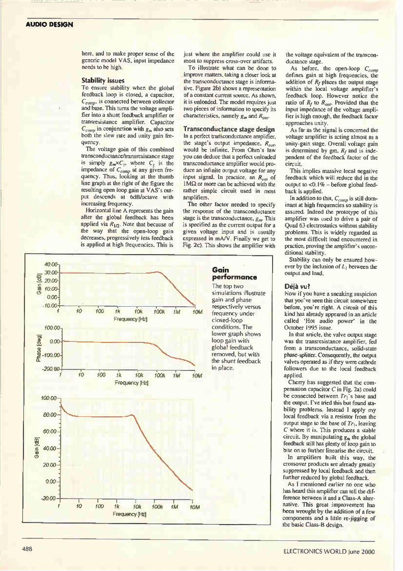
AUDIO DESIGN
here, and to make proper sense of the generic model VAS, input impedance needs to be high.
Stability issues To ensure stability when the global feedback loop is closed, a capacitor, Ce„„,p, is connected between collector and base. This turns the voltage ampli-fier into a shunt feedback amplifier or transresistance amplifier. Capacitor C, in conjunction with g„, also sets both the slew rate and unity gain fre-quency. The voltage gain of this combined
transconductance/transresistance stage is simply gxC',.., where C. is the impedance of C',.,„„p at any given fre-quency. Thus, looking at the thumb line graph at the right of the figure the resulting open loop gain at VAS's out-put descends at 6dB/octave with increasing frequency. Horizontal line A represents the gain
after the global feedback has been applied via Rif2. Note that because of the way that the open-loop gain decreases, progressively less feedback is applied at high frequencies. This is
just where the amplifier could use it most to suppress cross-over artifacts. To illustrate what can be done to
improve matters, taking a closer look at the transconductance stage is informa-tive. Figure 2b) shows a representation of a constant current source. As shown, it is unloaded. The model requires just two pieces of information to specify its characteristics, namely g„, and R„„,.
Transconductance stage design in a perfect transconductance amplifier, the stage's output impedance, R„,„, would be infinite. From Ohm's law you can deduce that a perfect unloaded transconductance amplifier would pro-duce an infinite output voltage for any input signal. In practice, an Row of 1 Ma or more can be achieved with the rather simple circuit used in most amplifiers. The other factor needed to specify
the response of the transconductance stage is the transconductance, gm. This is specified as the current output for a given voltage input and is usually expressed in mA/V. Finally we get to Fig. 2c). This shows the amplifier with
4000-
3000 co 2. 20 00-. Fa- 10 00-
000-
-Irmo
100 00-
ô, 000 -0
u, 'a -100 00-E.
-200 00
100 00 —
6000:
c 40 00 — (T)
20 00
000:
20 00
10 100 1k 10k 100k 1M
Frequency [Hz] 10M
10 100 1k 10k 100k 1M
Frequency [Hz]
1 10 100 1k 10k 100k 1M Frequency [Hz]
10M
Gain performance
The top two simulations illustrate gain and phase respectively versus frequency under closed-loop conditions. The lower graph shows loop gain with global feedback removed, but with the shunt feedback in place.
the voltage equivalent of the transcon-ductance stage. As before, the open-loop Cc.„,„p
defines gain at high frequencies, the addition of Rf places the output stage within the local voltage amplifier's feedback loop. However notice the ratio of Rf to Rom. Provided that the input impedance of the voltage ampli-fier is high enough, the feedback factor . approaches unity.
As far as the signal is concerned the voltage amplifier is acting almost as a unity-gain stage. Overall voltage gain is determined by gm, Rf and is inde-pendent of the feedback factor of the circuit. This implies massive local negative
feedback which will reduce thd in the output to <0.1% — before global feed-back is applied. In addition to this, C is still dom-
inant at high frequencies so stability is assured. Indeed the prototype of this amplifier was used to drive a pair of Quad 63 electrostatics without stability problems. This is widely regarded as the most difficult load encountered in practice, proving the amplifier's uncon-ditional stability.
Stability can only be ensured how-ever by the inclusion of LI between the output and load.
Déjà vu? Now if you have a sneaking suspicion that you've seen this circuit somewhere before, you're right. A circuit of this kind has already appeared in an article called 'Hot audio power' in the October 1995 issue.
In that article, the valve output stage was the transresistance amplifier, fed from a transconductance, solid-state phase-splitter. Consequently, the output valves operated as if they were cathode followers due to the local feedback applied. Cherry has suggested that the com-
pensation capacitor C in Fig. 2a) could be connected between Tri's base and the output. I've tried this but found sta-bility problems. Instead I apply my local feedback via a resistor from the output stage to the base of Tri, leaving C where it is. This produces a stable circuit. By manipulating gm the global feedback still has plenty of loop gain to bite on to further linearise the circuit. In amplifiers built this way, the
crossover products are already greatly suppressed by local feedback and then further reduced by global feedback. As I mentioned earlier no one who
has heard this amplifier can tell the dif-ference between it and a Class-A alter-native. This great improvement has been wrought by the addition of a few components and a little re-jigging of the basic Class-B design.
ELECTRONICS WORLD June 2000

AUDIO DESIGN
o
•I•ci 100n
Input R4 18k
O j R5 10k
Tr7 BC337
R6 10k
100n
R1 15OR
BC327
BC327
Tr2
R7 10k
R8 R2 R3 470R 33R 33R m. 100µ
Tr5 BC327
Tr6 BC327
Tr8 BC337
All 100R
Circuit details The circuit schematic is shown in Fig. 3. It consists of two sub-circuits, a transconductance amplifier and the VAS/output stage. A fundamental requirement of the
trans-shunt circuit is that the input volt-age signal should be converted into a current to drive the transresistance out-put stage. Here Tr' and Tr2 together with R1 and R7 form a conventional constant current source for the input transistors Tr3 and Tr4. These are oper-ated as a differential pair. Input signals are coupled into Tr3's base via the dc blocking capacitor C2. The input impedance is set by the value of R4 that also refers Tr3's base to OV. To produce the high output
impedance required from a transcon-ductance stage, Tr5 and Tr6 are used cascode with Tr3 and Tr4. Emitter degeneration is used, R10 and R11, to linearise the stage. Transistors Tr5 and Tr6 are biased by the voltage divider R5 and R6. The output impedance at Tr5's col-
lector is in the order of a megaohm or so. This is sufficient to reduce the dis-tortion of the driver/output stage to low
T 10n
C5 220p
R12 47OR
Tr11 MPSA13
R13 68k
levels when shunt feedback has been applied. To prevent the high output
impedance from being compromised a current mirror Tr7 and Tr8 are used. High gain n-p-n transistors are used here, emitter degeneration being pro-vided by R10 and R11.
Driver stage design Turning to the driver stage, in order to apply a large amount of shunt feedback around the output stage, the driver needs a high input impedance. Preferably this should be infinite. The idea that at single common-emit-
ter stage can provide this is a fallacy. The typical driver transistor has a low Hfe, leading to input impedances in the range of a few kilo-ohms. This shunts directly across the transconductance amplifier's output and effectively reduces the feedback factor of the cir-cuit, To avoid this a Darlington transistor,
Tri is used as an emitter follower buffer. The voltage amplifier stage proper is Tri2 a conventional common-emitter circuit. Applying masses of feedback around
BC337
R16 > 15OR
MPSA92
R17 1k2 AAA
R18 < 330R
R19 1 k2
Tr12MP
Mains input
Tr10 10N20
Tr13 10P20
—50VDC
the output stage is all well and good provided that the voltage amplifier has sufficient open-loop gain to make it viable. Single pole compensation could be used but to maintain maximum loop gain through the audio band double pole compensation is better. Doug Self described this technique in a previous issue 1.
Initially double-pole compensation starts to roll-off at 12db/octave. At hf however it reverts to a 6dB/octave roll-off to ensure stability. In this design the double pole network consists of C7, C8 and R20. Component values have been chosen
so that R20 doesn't load the voltage amplifier collector circuit unduly with-in the audio band.
R22 1R0
3W ceramic
H•
R21 1OR
C9 100n
o
Output
Fig. 3. 100W power amplifier and its conventional power supply. Unusual features are the feedback path via C6 and the network comprising C7,8 and R20.
June 2000 ELECTRONICS WORLD 489

AUDIO DESIGN
Choosing an output stage The choice of output stage is always a fraught one for designers. Several pos-sibilities present themselves. During development of this design I
have used pure complementary, quasi complementary and V-fet output stages. Because of the large amount of negative feedback applied I haven't noticed any sonic differences worth talking about. But a 100W amp is not a project for the squeamish! Considerations of ruggedness and
device longevity are paramount. In the end I chose V-fets for the output stage. Suitable n and p-type devices are read-ily available. Furthermore the staie is immune to
thermal runaway due to the Vfet's neg-ative temperature coefficiént and will shrug off a short circuit load. Don't try this one with bipolar transistors. Staying with the output stage stabili-
ty compensation for driving reactive loads is given by the network compris-ing C9 and R21 and the output inductor Li. This latter component comprises 15 turns of 18 SWG enamelled wire wound around a 3W wire-wound resis-tor, R22. As described earlier local shunt feed-
back is applied around both the VAS
and output stage via R13. Capacitor C6 prevents compromise of
the amp's dc conditions. Components R12 and C5 ensure hf stability and introduce a little more feedback at the high frequency end of the audio spec-trum. This shunt feedback network reduces the distortion to below 0.1% before global feedback is applied. Input impedance at Tr9's base is also
reduced by this feedback to less than 100iI. Thus the trans-shunt circuit is returned by feeding the current drive from Tr5 directly Into Tri i's base. Global feedback is applied through R9 to Tr4's base. In conjunction with Rg, R9 sets the voltage gain and C4 reduces the de gain to unity while pass-ing ac signals. This component also sets the —3db point of the amplifier at approximately 3.5Hz Finally the power supply. This is
entirely conventional in design. As the current drains of the various stages are defined with constant-current sources, the amplifier can operate from ±20V to ±50V supplies without modification. These supplies roughly represent power output ratings from 20 to 100W continuous into 8S1 loads. Heat-sink size must of course depend
on the amount of power required. For
maximum, output a minimum MN/ per channel sink is recommended.
Putting it together As far as implementation is concerned, the usual rules of good layout should be adhered to. Keep input wiring away from the output and use screened lead for the input. The easiest way to set the quiescent current is as follows. . Temporarily solder a 1001-2 resistor between Trio and Tri3's drains and the supply rails. Don't attach a load to the amplifier yet. Power up and check that the output is within 50mV of OV. If there are any wiring problems at this stage, the 100S1 resistors will be the only casualties! Switch off, remove the 1001.1 resis-
tors and reconnect the drains to the supply. The amplifier is ready to use. In conclusion I suggest that this
amplifier, with its low distortion and low power requirements, wilrfulfil the needs of most audiophiles. Having had mine operating for over six months. I haven't felt the desire to change it for a commercial model, regardless of price.
Reference L Self. Douglas. 'Distortion in power amps 7'
Electronics World, Feb 1994
Number One Systems Professional PCB Layout for Windows at Uornputer Store Prices!!
Easy-PC For Windows Version 3.0 of this outstanding product is the
latest evolution of one of the most popular
affordable CAD systems available. With power-
ful new features and a true Windows graphical
user interface, it is also one of the easiest to learn and use.
With full manufacturing outputs using Gerber,
Windows printers, N.C. Drill and pen plotters it
is one of the most complete systems for the
casual to the professional user.
Run multisheet Schematics, PCB layouts and
library manager all at the same time in the
same interface. Switching between each is
simply case of selecting the window with the
mouse without running a new program.
Now with our new autorouter option.
Runs under Windows 95/98 TM and NT'm
For a free demo disk, visit our web site www.numberone.corn Number One Systems. Oak Lane.Bredon. Tewkesbury, Glos. GL20 7LR UK
401.0, 1•10•4..., Ile.• ',T'eues 0'1 Ilemon I p.
Flt Leu 0.*, 1.* 1:1*.*
4.1
• _900 - -
io oo po
o o
o
e.
• 0 0 0 0 0 0 0 0
0 0 •
r •
g
o 10• ,101 • a a
0 • a 0 • a a 0 a a
0 0 • 0 a •• 00
0. 0 a a
frai/a
o
. 0 0 Cl 0 00 0 0 oe 000000 0,63
0 a 0 0 a fi
0 a
From
£97
wrg 1‘.
S.., V. Fr. 0. SM. 0.1., 10 03 Nor NO1117 La, Tao Eheratal Abd tala 09 157, 95 •••••
Number One Systems Call 01684 773662 or Fax 01684 773664
Email [email protected]
CIRCLE NO.119 ON REPLY CARD
ELECTRONICS WORLD June 2000

Pico ADC42 Virtual oscilloscope Featuring 12-bit resolution and 1M12
input impedance, the ADC42 samples
at up to 15kS/s and includes software
for spectrum analysis, oscilloscope
functions and frequency display.
Plugging into a PC's LPT port, the unit
provides large, colourful displays and
all the usual timebases and trigger
options — all in a case slightly larger
than a matchbox.
ADC42 single channel oscilloscope
• Low cost and easy to use • No power supply required • Ultra compact design • Oscilloscope and data logging software
included • Write-to-disk on trigger function standard
The ADC42 is a single-channel pc based virtual instrument. Simply plug the unit into the parallel port of your pc an run the software. Designed for analysing low-frequency signals. it provide all the functionality of a conventional scope at a fraction of the price. The ADC42 has 12-bit resolution making it
suitable for applications where detection of small signal changes is needed.
Specifications Scope timebases Spectrum analysis Max sampling Voltage range Resolution Channels I/P impedance Accuracy PC connection Power supply
500ps/div to 50s/div 100Hz to 10kHz 15ksample/s -±-5V 12 bit 1 BNC 1M12, dc coupled 100
D25 to PC parallel port Not required
e I
UK onl. Overseas readers please fax or e-mail for a quote including delis ery charges.
kielellu=ifica Ear
MI-LE
a"leniasa•-llidé
75 owe ti o e.% $.1 sbe Fi ri
m ums on
i-ImiiiiliM=117
4881Iz
Use this coupon to order your ADC42
Please send me ADC-42(s) at the special offer price of £98
fully inclusive of VAT and recorded UK delivery, normal selling price
£111.63 excluding postage.
Name
Address
Phone number/fax
Total amount £
I enclose a cheque
Please charge to my credit/debit card.
Card type (MasterNisa/Switch etc)
Card No
Expiry date
Please mail this coupon to Electronics World. together with payment.
Alternatively fax credit card details with order on 0181 652 8111.
Address orders and all correspondence relating to this order to Pico
Offer, Electronics World, Quadrant House. The Quadrant, Sutton,
Surrey SM2 5AS.
email [email protected]
Make cheques payable to Reed Business Information Group.

CONTROL ELECTRONICS
Become a trapezium expert There's any number of circuits for generating square, sine and triangular waveforms, but you rarely see anything on producing trapezium waveforms. Here, Anthony Smith not only explains how to make trapezium waveforms, but also reveals why they can be so useful.
ou needn't search too hard if you want to generate a sine, square, triangular or sawtooth waveform: textbooks and cookbooks have all sorts of ideas for
generating them. However, whether you consider it to be a clipped triangle or a slew-limited pulse. the trapezium wave seems to get scant mention in much of the literature. Applications for trapezium waveforms are surprisingly
varied. I first encountered this versatile waveshape when working on Highway-Addressable Remote Transducer, or HART. communications systems. An outline of HART is presented in a separate panel.
+Vs (+5V)
Fig. 1. Switched current mirrors and
a simple diode clamp define the trapezium on C.
Motor and power control Trapezium waveforms find applications in active device testing. where they can be used to model real-world digital signals having finite rise and fall times. Since the trapezium can form a good approximation to a
sine wave, it is also used extensively in motor controllers for three-phase systems, induction motors, etc. Here, the relative ease with which the amplitude and frequency of the trapezium can be controlled makes it an attractive alter-native to sine wave control. As well as being used to provide drive for motors, the
H
(R1, R2, CL, Tr1-Tr4: see text)
492 ELECTRONICS WORLD June 2000

CONTROL ELECTRONICS
trapezium wave may also be used to control a motor's velocity, a typical example being the printfhead drive motor of a dot matrix-printer. Known as 'trajectory profile generation' and 'velocity
contouring', such methods use the trapezium shape as a control signal. The rising and falling edges determine the acceleration and deceleration of the motor. A separate panel entitled 'Trapezium waveform param-
eters' shows how the RMS value of a trapezium voltage may be varied from a minimum of V pl.V3 to a maximum of Vp simply by altering the slope of the rising and falling edges. Consequently, the trapezium lends itself to RMS regulation techniques, whereby the power to a load may be controlled either by adjusting the 'crest' width, t, while keeping the rise and fall times constant, or by adjusting only the slope of the edges. For systems where the load parameters are known and constant, the power may be con-trolled by sampling the peak load voltage and using pulse-width modulation to adjust the relative width of the trapez-ium crest.
Rings a bell... The trapezium waveshape also finds applications in telecommunications systems such as dual-tone multi-fre-quency, or DTMF, telephone dialling circuits. Here it is used to approximate a sinusoid. Dual-tone multi-frequency dialling signals make use of
two simultaneous sinusoidal tones of different frequencies to represent each key on a telephone keypad. To ensure compatibility with DTMF receivers, the tones must have accurately defined frequencies. This may be achieved by generating low-pass filtered trapeziurh signals that are fre-quency locked to a crystal reference. The signal that rings the telephone bell may also be
trapezium shaped, or may be a pseudo-sinusoid formed by low-pass filtering a trapezium-shaped waveform. The Harrisantersil HC55171 ringing Subscriber-Line Interface Circuit, or SLIC, for example, can produce sinusoidal or trapezium-shaped ringing signals. Bellcore ringing specifications set limits on the ringing
signal characteristics, particularly On crest factor, which is the ratio of peak voltage to RMS voltage, and the mini-mum RMS ringing voltage. Bellcore specifies a crest fac-tor range of 1.2 to 1.6.
It can be deduced from the separate panel that the trapez-ium's crest factor ranges from unity to Ni3, i.e. 1.732. So by adjusting the trapezium's shape to provide a crest factor less than that of a sinusoid, which is 1.414, the RMS volt-age available to the handset can be maximised. This results in more ringing power and an increase in the allowable loop length between the handset and the SLIC.
Slew-rate control In high-speed datacomms applications, such as Low-Voltage Differential Signalling, or LVDS, where data rates up to 400Mbits/s are feasible, crosstalk and EMI are of particular concern. Devices such as Texas Instruments' SN65LVDS31
LVDS drivers' allow the user to minimise these effects by connecting a capacitor across the differential output. This reduces the slew rate of the output pulses, resulting in a trapezium signal shape, thereby minimising the harmonic content of the transmitted signal. Slew-rate limiting techniques are not new. They have
been used to good effect in other devices such as National Semiconductor's DS3662 high-speed trapezium-waveform
bus transceiver. Each of the DS3662's quad drivers gen-erates a precise trapezium waveform having rise and fall times of 15ns. This slew-rate limiting reduces noise coupling to adja-
cent bus lines: when used with the low-pass filtering inher-ent in the DS3662's receivers, the performance in terms of data rate versus line length can be an order of magnitude better than that achieved with other transceivers that do not have slew rate limiting2. Recently, new devices have appeared that offer pin-
selectable slew-rate control. Linear Technology's LTC1535 isolated RS485 transceiver, for example, has a 'slow slew-rate select' pin. Via this pin, typical driver tran-sition times can be increased from 2Ons to around 50Ons to
Fig. 2. Switched current mirror - undamped response. The middle and bottom traces compare Voia using general purpose transistors and fast-switching transistors respectively, both at 2V/div. The top trace shows VIN displayed at 5V/div. and the time-base was set to 20Ons/div.
Fig. 3. Switched current mirror, clamped response using general-purpose transistors. The middle trace is Votyr with CL at 10pF and the bottom trace is Vouj with a CL of 230pF. Both are at 1V/div. The top trace is VIN at 5V/div. The time-base setting was 20Ons/div.
Trapezium therapy
The trapezium wave can benefit not only electrical systems, but neurological ones, too. Electrical stimulation has been used in nerve therapy where trapezium-shaped pulses are applied to a damaged nerve by way of electrodes attached to the patient's skin3. Having a frequency range of 60 to 250Hz and an RMS voltage of around 20V, the pulses can be used to stimulate damaged nerve tissue back to its normal, healthy function. Although it is not completely under-stood why pulses of a trapezium shape are so effective in this form of treatment, the technique can return a damaged nerve to near normal condition and is particularly successful in cases where nerve damage has resulted in hearing loss.
June 2000 ELECTRONICS WORLD 49 3

CONTROL ELECTRONICS
+Vs (+5V)
100nI 10u
ICla 74AC14
^ VN
(0 to 5V)
100n:
10p.
14
7
Notes: ICid - 1f and IC2c - 21 not used. R2. R3, CL, VUIGH, VLE,„„ - see text.
• Cl D1
B Y88C 100p1" 5V6
R1 r 4k7
Fig. 4. Bipolar trapezium-waveform
generator with improved
clamping circuit.
'Gib
RE, 5R1
(0.1%)
Tri BC556B
R2
IC2a 74AC14
14
•
IN1
minimise EMI and line reflections. There is, of course, a price to be paid in terms of
reduced bit rate and an increase in supply current during the slow slew-rate edges.
Practical circuits What, then, is the best way to produce a trapezium waveform? For general test purposes I needed to generate a
trapezium waveform whose positive and negative peaks could be varied over a range of at least ±5V. I needed a broad frequency range — from a few hertz up to at least several hundred kilohertz — and the positive and negative slopes had to be independently adjustable, with an upper limit of at least ±10V/is. The need for fast slewing prompted me to discount
d-to-a converters and digitally-controlled resistor net-works: I wanted a solution that would provide inher-ently smooth, linear ramping between peaks — a desire that led, inevitably, to the charge and discharge of a capacitor. A simple way of achieving this is shown in Fig. 1.
Here, switched current mirrors formed by Tri with Tr3 and Tr2 with Tr4 provide charge and discharge currents for load capacitor CL. Simple diode clamping, comprising DI, D2, V Low
and VNIGN, buffered by emitter followers Tr5 and Tr6, defines the upper and lower peaks of the trapezium. A rectangular input signal, VIN, that swings from OV to +Vs, determines the current injected into each mirror. For example, if you assume the n-p-n mirror is
ideal, i.e. Tr2 is perfectly matched to Tr4, then the discharge current, /c-4,is given by,
•
RE3 5R1
(0.1%)
Tr3 BC556B
: c,
Tr4 / BC546B
RE4
5R1 (0.1%)
Tr6 BC556B
R 2
Clearly, the charge and discharge currents, /C3 and /c4, and hence the rising and falling edges of the trapezium can be controlled by adjusting R1 and R2. In practice, any mismatch between the mirror transis-
tors can be mitigated to some extent by emitter resistors RE1_4. These also impart a degree of temperature stabil-ity and increase the output resistance of the mirror's.
Prototype performance 1 decided to test the circuit using both general purpose transistors (p-n-p BC177B; n-p-n BC108B) and fast, switching transistors (p-n-p ZTX510; n-p-n ZTX314). Static performance was reasonable considering that the
devices were not matched in any way: the worst-case current matching error for the general purpose devices was around 130%, whereas for the Zetex ZTX parts, the error was a more respectable 48%. However, it was the dynamic performance that sorted the men from the boys. Figure 2 shows circuit response with the output
unclamped, i.e. Tr3 and Tr4 allowed to saturate. Resistors R1 and R2 were set at lkil, and CL at 10pF, representing the probe capacitance. The middle trace illustrates the saturation effects of
the general purpose devices: the p-n-p transistor, Tr3, takes around 100ns to come out of saturation, whereas the n-p-n part, Tr4, takes around 400ns. The bottom trace shows the circuit response with the general pur-pose transistors replaced by the Zetex parts: response from saturation is now almost instantaneous.
R5 4k7
+5V
494 ELECTRONICS WORLD June 2000

CONTROL ELECTRONICS
Since Tri4 form a complementary current mirror, out-put transition time will depend on the turn-on time delay of a given output transistor combined with the turn-off delay of the complementary device. In general, the turn-off delay of a bipolar transistor tends to be much greater than the turn-on delay. Turn-off delay is dominated by the 'storage time', during which the device is saturated and an excess of charge builds up in the base region5.
It follows that switching performance can be optimised by selecting transistors specifically designed to minimise the storage delay: refer again to the bottom trace of Fig. 2, where it takes around 7Ons after VIN rises before Vow- starts to fall (the p-n-p ZTX510 has a maximum turn-off time of 9Ons), and roughly lOns after VIN falls before Vow- starts to rise (the n-p-n ZTX314 has a maximum turn-off time of 18ns). Alternatively, it should be possible to minimise the turn-
off delay using general purpose devices by keeping the transistors out of saturation. The middle trace of Fig. 3 again shows the output response using only the general pur-pose transistors; this time though, DI and D2 are connected to CL, and V Low and VHIGH have been set to clamp Vour at +1V and +4V. Notice how the output signal responds immediately to
A2 2,6 't11 200' Jr
\
2013ns
changes in VIN — turn-off delay is almost completely absent. The bottom trace of Fig. 3 shows the output response with CL increased to around 230pF. The resulting trapezium slews cleanly between the clamp levels at a rate of about ±12V/ps.
Fig. 5. Bipolar
trapezium
clamped at +2V and —3V with C1
at 110pF. The
upper trace is
VIN at 5V/div.
and at the
bottom, VouT at 1V/div. The time-base setting was
20Ons/div.
Trapezium waveform parameters This diagram shows an idealised case where a rectangular input signal results in a trapezium output waveform whose time and amplitude characteristics can be independently adjusted.
In this example, the positive peak, Vp , is greater than the negative peak, VN , and the positive slope is steeper than the negative slope, such that the rise time, t„ is shorter than the fall time, tf. Clearly, the 'crest' time, tc, can be adjusted by varying the width of the input pulse. For the case of an amplitude-
symmetrical waveform, i.e., when I Vp1= IVNI such that (tr-ftei-ti)=T/2, i.e., equal to half the period, the RMS value of the trapezium is given by,
t + t V„, = 4'3Tf
It you let tr=tf and make tc=0, we find that,
V V = RAIS
which should be familiar as the RMS voltage of a triangle wave having peak amplitude Vp. On the other hand, if you make tr=t1=0, such that tc=T/2, the RMS value reduces to V RAis=V p, representing the case of an ideal, symmetrical square wave. An interesting case arises when
t,=tf=t,=T/6, resulting in,
Vus =V e s p 8
which is very nearly equal to Ve12. This shows that when the rise time, fall
time and crest time of the trapezium are
all equal, the RMS value is very close to that of a sine wave with peak amplitude V.
Fourier series If you consider an amplitude-symmetrical trapezium that is also time-symmetrical, i.e., when tr=tf, the waveform can be represented as a function with the following Fourier series,
sin(K) x sin(ax)+
— x sin(3K).sin(3ox)+
F(t)=i El( —xsin(5K)x sin(5aTi)+
— x sin(7K)x sin(los) + 72
where the higher terms have been omitted, and where K=2EtiT and co=2n/T.
If you again consider the case where ty=t1=T/6, the series reduces to,
Rectangular input signal
Trapezoidal output signal
• ( K3 ) sin — x sin(OS) +
—I x sin(x)x sin(3ax)+
F(1‘=' 1£-'322 ir2
x sin( r)x sin(5ax)+ 5 3
2x sin(LT)x sin(7att)+ ... 7 3
can be simplified to,
11.053 x sin(an)+ F(t)= V, 0 x sin(3ca)-0.042.sin(5ax)+
0.021 x sin(7ax)+...
which
Clearly, the sin(3cut) term drops out — as do all other harmonics divisible by 3 - and ignoring higher harmonics which are small in amplitude relative to the fundamental, the expression becomes F(t)=1.053Vesin(wt), which is very nearly the same as a sine wave of amplitude Vp and frequency t= 1/T.
Generating a trapezium-shaped wave, with fully
adjustable parameters, in
response to a rectangular
input signal.
Negative slope
June 2000 ELECTRONICS WORLD

CONTROL ELECTRONICS
+Vs (+5V)
100n
VIN (0 to 5V)
OV
10p .
100n
-Vs (-5V)
Bipolar swing A bipolar version of the circuit is shown in Fig. 4 where C1, DI and RI form a crude level shifter which transfers /Cia's positive output pulses to /C2„.b. Thus. R3 is driven by a signal swinging from —Vs to OV. which is in phase with the signal swinging from OV to +Vs that drives R2. Complementary emitter followers Tr5_8 form an improved
clamp circuit: assuming the Vs of the n-p-ns are roughly equal to those of the p-n-ps, the upper and lower peaks of the trapezium will equal VHIGH and Vww, respectively. Figure 5 shows the high-frequency response, again using
only general purpose transistors, and with CI, at 110pF. Resistors R2 and R3 were adjusted to set 1c3 at 2.75mA and Ic4 at 0.92mA, resulting in slopes of +25V/ps and —8.4V/ps. The clamp circuit performed well: the values of VHIGH and VLOW required to establish a swing from —3V to +2V differed by less than 50mV from the actual levels observed. However, the trapezium's peak-to-peak swing is limited by the base-emitter breakdown voltages of Tr5.6 and must not exceed VaiReB0-1-VBE, where V(BR)EB0 is the minimum breakdown voltage of either Tr5 or Tr6. For the devices shown, having a minimum V(BR)E80 of
Fig. 6. Using Baker clamps and a transistor array to generate high-voltage trapeziums.
IC1a 74AC14
10p .
3 •
5
14
RE1 5R1
(0.1%)
10
Tri Notes: Tri - Tr5 = CA3096. 12 IC1d - 1f and IC2c - 2f not used. R2, R3, CL, VHIGH, VLOW - see text.
2 •
7
C1 100p
R1 4k7
• D1
BZY88C 5V6
IC1b
7
02 1N4148
• 4 •
D3
around 5V, the swing must be limited to less than 5.6V pk-pk. Nevertheless, provided this condition is met, VHIGH and VLOW can be adjusted in conjunction with R2 and R3 to create trapezium, triangular and sawtooth waveforms that lie anywhere between the —5V and +5V rails.
High voltage swings A variation on the above theme is shown in Fig. 6, which is capable of generating high-voltage waveforms. The trapezium slopes are again controlled by R2 and R3. These components determine the currents injected into the com-plementary mirrors via Tr5 and Tr6. Voltages VHIGH and VLOW are no longer used to clamp
the waveform. Instead, they establish the upper and lower limits of the trapezium by varying the supply rails to the mirrors. However, for good high frequency response, it is still necessary to keep Tr3 and Tr4 out of saturation. The Baker clamps formed by D2.3 and D4.5 achieve this. Baker clamps have been used extensively in switched-
mode power supplies6. In such designs, the bipolar tran-sistor that drives the magnetic components must be kept out of saturation in order to ensure fast switching and thus
14
1N4148
R2
Tr6 BC556B
D5 1N4148
IC2
3
Tr2
2
RE2 5R1
(0.1%) T
RE3
5R1 (0.1%)
13
Tr3
15 •
C3
VOUT
VHIGH
OV
C4
6
Tr4
VLOW
CA3096 pin 16
4 (Substrate) o
RE4 5R1
(0.1%)
496 ELECTRONICS WORLD June 2000

CONTROL ELECTRONICS
maintain high efficiency. In Fig. 6, D2 and D3 ensure that Tr3's collector-emitter
voltage cannot become less than its V BE drop. When Tr5 is driven 'on' and sinks current through D2, the collector voltage of Tr3 rises at a rate determined by /c3 and CL until it is high enough to forward bias D3. At this point, D3's anode potential will equal that of D2 - assuming similar drops across each diode - effectively clamping the col-lector of Tr3 to the same potential as its base. Consequently, the trapezium peaks at a level just below % Gib determined by Tr3's VBE drop and the small drop across R E3. Diodes D4 and D5 provide a similar function with Tr4.
Transistor array I decided to test the circuit using a Harris/Intersil CA3096 transistor array for Tri.5. This IC provides a degree of match-ing between the transistors in its n-p-n and p-n-p pairs - but beware that only the 'A' version offers guaranteed matching.
Static performance was impressive. With VHIGWVLow at ±5V, and /c/ and /c2 set to 2.0mA, currents /c3 and /c4 dif-fered from this value by no more than 4%, although this error increased to 15% with VH/Gie Low at ±15V. Figure 7 illustrates dynamic performance. Here, R2 and R3
were selected to yield slopes of +25V/ps and -50V/ps across a load capacitance of around 66pF. Levels %/HIGH and VLow were adjusted to swing the trapezium from -10V to +15V. For exactly the same conditions, Fig. 8 details the output
response with the Baker clamps disabled, i.e. with D3 and D5 removed. You can see that the output signal now takes about 150-20Ons to respond to transitions of VIN, the sluggish response being due to saturation of Tr3 and Tr4. The peak-to-peak swing of the trapezium must be limited
to a value less than the collector-emitter breakdown voltage, V(BiocEo, of Tr3 and Tr4. Since the minimum V(BR)CEO for the CA3096 devices is 35V, a safe limit would be around 30V pk-pk. However, if high-voltage transistors were employed, such as MPSA44s for the n-p-ns, and MPSA92s for the p-n-ps, and provided D3, D5 and CI., were also suitably rated, it should be possible to generate waveforms with amplitudes exceeding 100V pk-pk.
+Vs (+15V)
lOtt
Fig. 9. Combining a d-to-a converter and Wilson current mirror provides digital control of the trapezium's slopes.
OV
R1 (see text) IREF
R2 (see text)
1-
100n:
13
la
15
Full scale
Half scale
Zero scale
Input code
11111111
10000000
00000000
Digital control of an improved mirror The output resistance of the simple current mirror considered so far can be approximated by R0=VA//c, where VA is the output transistor's Early voltage, and /c is output current7. 8.
Load current. I L
44255/256).1a,,
+0/256)
-(255/256).f:,,,
8-bit digital code (0 to 5V logic levels)
MSB 0 o
5
V.
6
REF(*)
1N4148
1N4148
7 8
o o O o 0 LSB
9 10 11 12
B, B, B. B, 13, e. B.
IC1 DAC08
COMP
16
-4 C, 10n
0-1
IOU
IOU,
RE, 25R
(0.1%)
Tri BC556B
D1 1N4148
4 oui
2
-Vs (-15V)
CL (see text) Cl
100n
R3 487
Fig. 7. Generating a -10V/+15V trapezium with Baker clamps active. AI the top is VIN at 5V/div.and at the bottom is the output waveform at 5V/div. In this case, the time-base was 50Ons/div.
Fig. 8. Output response for same conditions as Fig. 7, but with Baker clamps removed. The upper trace is VIN at 5V/div. and at the bottom, the output waveform at 5V/div. Time-base setting, 50Ons/div.
Tr5 BC5568 \
+15V
C2 .."100n
7
15V
OV
June 2000 ELECTRONICS WORLD 497

CONTROL ELECTRONICS
What is HART? In the HART system, 'smart' devices, such as temperature transmitters and actuators, use the HART protocol to communicate with a central controller. They communicate by superimposing digital signals on a conventional 4-20mA current loop using phase-continuous frequency-shift keying at 1200Hz/2200Hz. The protocol calls for a balanced AC signal with zero DC content that
will not disturb the 4-20mA loop signal. A sinusoid would be the preferred waveshape, but generating a phase-continuous FSK sine wave is not so simple. Slew-limiting the edges of the square wave digital signal, however, can produce a trapezoid, relatively easily. With suitable amplitude scaling, the resulting 'pseudo-sinusoid' is then
coupled to the 4-20mA loop allowing a mass of information - such as tag numbers, range and span data, and diagnostics - to be communicated between Smart devices.
Rarely quoted on transistor data sheets, VA might range from 50 to 100V, depending on the device used. Clearly, for lc greater than 2mA, Ro will be less than 501d1 - hardly an optimum value for a current source! This relatively low output resistance causes slight changes
in the output current as the voltage on CL varies, an effect that manifests itself as a curvature in the trapezium's slopes. This non-linearity can just be discerned from Figs 7 & 8. Here, the slope of the rising edge, for example, varies by as much as 7% from its nominal, mid-slope value of +25V/,us. Output resistance can be greatly increased by using a
Wilson current mirror as in Fig. 9. The mirror's output cur-rent, I, is controlled by the d-to-a converter. This circuit is a modified version of a circuit9 intended to provide precise, digital control of the bipolar current fed to an external load. The high-speed, eight-bit d-to-a converter, /CI, generates
complementary output currents louT and /our . These actu-ally flow into the device, the sum of which equals the full-scale current, IFS, for all values of digital input code. The load current, IL, flowing into CL is given by,
= - lour . Assuming the Wilson current mirror formed by Tri_3 to be ideal, then /0 =/our, such that.
= 'OUT - Icitif
Since,
'OUT 4- 1011T = IFS
you will find that /L=2/our-/Fs . The magnitude of /our depends on the input code and IBEE,
where 'BEE is the reference current given nominally by VREF/Rt• In particular, loo2=(INPUTCODE1256) X--1REF. Since /Fs=(2.5.5/256)x/REF, you will find that,
Fig. 10. Linear response of the d-to-
a converter controlled trapezium
generator. The top trace is the input
signal applied to B B3 and B5 displayed at 5V/div. All other bits are low. At the bottom you can see
the output signal ramping from -7V to +10V, also at a setting of 5V/div.
The time-base used was 1 ps/div.
/ { (2 x INPUTCODE)- 255 = „
1 „.
256
Therefore, IL is a bipolar current ranging from -O.99ólREFtO +0.996/REF as shown by the table in Fig. 9. By switching the input code between suitable levels, the voltage on CL can be made to ramp up and down at precise rates, thereby allowing digital control of the trapezium slopes. Diode DI with Tri.3 form a modified Wilson current mir-
ror. The presence of Tr3 increases the output resistance8 of the simple, two-transistor mirror by a factor of W2, where 13 is the common-emitter current gain of the transistors used. Diode DI, which could be another p-n7p transistor, balances the VBE of Tr3, forcing the collector potentials of Tri and Tr2 to be equal. This improves the matching of IC3 to low- .
Linear response With a total load capacitance of around 130pF - which includes CL, probe capacitance, and the capacitance of Tr3, D2, D3 and pin 2 of /CI - and with IBEE set to 2mA, I tested the circuit's response. I did this by switching the input value from 000000002 to 101010002 at about 160kHz. Levels VLow and % GI, were adjusted to clamp the trapezium's peaks at -7V and +10V, as in Fig. 10. I found that the measured output current levels - and,
hence, the trapezium slopes - differed slightly from calcu-lated values, due, simply, to matching errors in the mirror. However, the rising and falling edges were perfectly linear, with no discernible 'curvature'. Output swing must be constrained to prevent Tr3 from sat-
urating. It must be at least two VBEs below +Vs. The negative swing is limited by /C1's negative voltage compliance: this is around -10V with 1BEE at 2mA and -Vs at -15V.
Pulse-slope modulation Usually, R2, which is connected to the inverting input of the DACO8's internal reference amplifier, is made equal to /21 and tied to OV. Alternatively, it may be connected to a vari-able reference voltage to trim lour and /ow-However, by connecting R2 to an alternating signal, the
load current IL - and, hence, the trapezium's slopes - can be modulated. For example, with R2 fed by a low frequency sine wave, the trapezium's rising and falling edges became a blur as the dV/dt varied in proportion to the amplitude of the mod-ulating sine wave. This fascinating effect suggests that the circuit could be used for 'pulse-slope modulation'. I'll leave it to you to think of an application for this!
References I. "Slew Rate Control of LVDS Circuits", Texas Instruments
Application Report No. SLLA034A. 2. "DS3662 - The Bus Optimizer" National Semiconductor
Application Note AN-259. 3. "Method of nerve therapy using trapezoidal pulses", US
Patent No. 3881495, 6 May 1975. 4. "Analysis & Design of Analog Integrated Circuits" (p241-
p244) by P. R. Gray & R. G. Meyer (John Wiley & Sons, 1984)
5. "Microelectronic Circuits" (p399-p402) by A. S. Sedra & K. C. Smith (Holt Saunders, 1982).
6. "Switching Power Supply Design" (p325-p339) by A. I. Pressman (McGraw-Hill, 1991).
7. "Early Definition" (p474-p477) by Bryan Hart, Electronics World June 1999.
8. "Early Applied" (p591-p594) by Bryan Hart, Electronics World July 1999.
9. "Current Mirror Enhances DAC"; Alfred P. Neves, EDN 16 February 1989.
10. "Applying the DAC08", Philips Semiconductors Application Note AN I01 (1988).
498 ELECTRONICS WORLD June 2000

CONTROL & INSTRUMENTATION
Calibrator for 4-20mA After reeling at the price of a calibrator for 4 to 20mA loop interfaces, Darren Heywood decided to look into designing his own. He succeeded in making one that performs better than its commercial counterpart - and at a fraction of the cost.
The most important parameter of any instrument is its rate of output change with ambient
temperature, hence if long term stability has been accomplished then all that remains is to calibrate to a known source. I describe here a 4-20mA calibrator
of the type widely used in process industries. Equivalent commercial 4-20mA calibrators with a price tag of
12V
I.
Powe on LED
C2 10(in
R2 47R
U.C1 :470n
15
around £300 have a typical stability of 4pAIT at 4mA, best case. My circuit has a staggering drift
gradient of only 100nAPC at 4mA and 600nAPC at 20mA. This means it is some 40 times more stable then commercially available units.
Circuit overview My unit runs from eight I.5V standard AA batteries, i.e., I2V, the SG3524
o-->Battery 12V
Aciust for 26V
1) 4
Fig. 1. Supply generation — 26V from a 12V battery. It uses standard, and hence cheap, inductors and delivers up to 50mA.
• •
+12V
8
+12V O 135 1k
R15 51k MA&
R7 1k
R14 2k
PWM chip generates a 26V supply. This allows the unit to handle external load resistances up to I Id/ Transistors Tr' and Tr, are essentially
class C amplifiers that deliver a power pulse every half cycle. The supply can sustain 26V while sourcing some 50mA. The step up is accomplished without the need of a custom wound expensive transformer; instead two cheap easily available inductors are used. The SG3524 runs at about 200kHz.
Components Tr' and Tr2 run very cool under normal conditions, which means step up conversion is very efficient — a
+1 V
L1 1mH
390R
R10 2k R11
3R3
R13 390R
D5 1N916
Tr2 TIP41C
C5 22p 35V+
I H .
+12V
L2 D7 1mH 1N916
Tri TIP41C
R12 3R3 27k
1R 17
1'4 3k
)+26V
> Gnd
> —12V (not used)
June 2000 ELECTRONICS WORLD 499

CONTROL & INSTRUMENTATION
:R20 1k2
1N916
1N916
1N9
+12V
R19 2k R21
18k
R18 3k3
Fig. 3. Low battery monitor
lights the LED when voltage falls
to 10V.
Field instrument
+1 V
R23 1M8
Fig. 2. Control circuitry is based on an ICL7650 chopper-stabilised op-amp with an open-loop gain of around 30 000 000.
P6 Pot CIL.
Ps 20mA
P, 16mA
P3 12mA
R„
100k
R40 R42 100R 100k
C12 2 8mA 1100n
P1 4mA
R 26 560k
Lo batt. R24 820R
LED
pre-requisite for battery powered instruments. The main control circuitry comprises
an LM329C which is a 20 pprar reference of 6.9V. Its output is stepped down via R33 through R39. You can select 4 to 20mA in steps of 20% increments or decrements. Position 6 allows you infinite
resolution between 4 and 20mA with the aid of the ten-turn potentiometer. The switched positions are fed into
the excellent ICL7650 chopper-stabilised amplifier. This device has an open-loop gain of approximately thirty
4-20mA
4.5mA is drawn from the chart recorder to power the field instrument
2-wire system 11›
24V Chart recorder
OV
The chart recorder responds by monitoring the current 'pull on its 24V supp y. 4mA = zero, 20mA = full span.
The 4-20mA loop. Two-wire 4-20mA system use less cable than their four-wire counterparts and they give fewer ground-loop problems - but they pose more problems for the designer.
R25 1M8
—'VVVV
11
+12V R4,3 470R
C11 Moon
C7 100n
Re
14117 10k
million, i.e. 150dB. This device retails for as little as £3. Notice the floating offset correction
capacitors C7 and C8. The only drawback /C3 has is that its output impedance is quite high hence loading the output can gobble up much needed gain. To overcome this slight problem, Tr4 and Tr5 make up a localised current-feedback pair, providing a high input impedance. During development, I included a
buffer between /C2 and /C3. It totally spoilt the stability of the circuit and so I removed it. Resistors R33 to R39 inclusive should be 15ppm 0.1% types, but excellent stability is still possible with 5Oppm 1% alternatives. The unit is equipped with a low-
battery indicator, /C4. Should the battery fall below about 10V, LED 2 flashes on and off indicating that accuracy is no longer be guaranteed.
In use The unit has two modes of operation, 'Tx', in which it transmits and
100n
+26V o
4 Tx e SIM e
+ — + —
L3
560u H
C10 100n
R„ 1k
R45 100k
9
R49 47P VR3
100k 100R
D4
D5
D6
125mA
> + meter
1N916
1N916
1N916
> — meter
Tr4
2N3904
R47
200R
span
Tr,
2N2905A
'Sim', in which is simulates. In transmit mode, the unit sends 4
to 20mA into an external load. Simulate mode is used to simulate two-wire systems. I am not sure why process engineers call this mode 'simulate' as I feel it is a rather misleading term. In this mode, my calibrator sinks a 4-20mA signal from the instrument under test's own 24V supply and the calibrator behaves or 'simulates' a two-wire 4-20mA field instrument. Current being drawn through the 24V supply is measured. In the field, direct current mea-
surement is possible by connecting a DMM across diodes D4 through D6 without disturbing or breaking the current loop.
Calibrating When calibrating the unit, connect a 0.1% 15ppm 0.33W 2500 resistor across the Tx terminals. With a 61/2-digit bench multimeter switched to the volts range, measure the voltage across the 2500 resistor. Currents of 4 to 20mA will corre-spond to a 1 to 5V drop across the 250e resistor. Switch to position 1 and adjust the zero potentiometer for 1 V. Then switch to position 5 and adjust the span potentiometer for 5V. Repeat this procedure until
satisfactory results are obtained. •
500 ELECTRONICS WORLD June 2000

H7pe?rACTIV (electronicsWEEKLYonline) dew—
"Your passport to a better future"
"What a partnership!"
HyperAcTsve (electronicsWEEKLYonfine)

WE IRECTIONS AQUILA VISION http://www.aquila-vision.co.uk
Aquila Vision specialises in supplying and supporting Embedded Microprocessor Development products from PICs to DSPs. We also stock robotics boards. Linux and general interest CD-ROM's.
¡at
ALCATEL COMPONENTS http://www.components ©alcatel.de
ASHWELL ELECTRONICS
http://www.ashwell-hq.com
Ashwell provide technical support for Apex Microtechnology op-amps and DC/DC'S: Aeroflex: EMP filtered connectors: M S Kennedy: Mintech obsolescence: NSC Mil/Aero: Teledyne Relays and isocom mil/optocouplers.
ARCOM http://www.arcomcontrols.com/eW
.•fOoff, grub
lef000mmeff fa, u f000mbf • fume •
11-.43 »."
A leading international supplier of communication and control technology to industry, Arcom provides leading edge solutions through a comprehensive range of market leading products.
BROADERCASTING COMMUNICATIONS SYSTEMS
www.broadercasting.co.uk
WINRADIO now brings you a complete choice in personnel computer controlled radio scanning and reception solutions • Broadcast • Media • Monitoring • Professional Amateur Radio communications
BEDFORD OPTO TECHNOLOGY LTD http://www.bot.co.uk Optoelectronic products UK design development manufacture standard and
custom. LED bargraphs. circuit board indicators, stand offs. transmissive/reflective switches. baseefa optocouplers tubular and surfacemount. pannel mount LED assemblies.
CONCEPT ELECTRONICS
http://www.conceptkey.co.uk
Concept Keyboards are specialists in the design and manufacture of customer specified membrane panels and keyboards. and electronic design. Concept's membrane manufacture is supported by a full electronic production facility to provide a complete turnkey keyboard and electronics service, fully accredited to IS09001.
CONTROL SOLUTIONS www.controlsolutions.co.uk Data acquisition and control for beginners, hobbyists, and professionals. Perform mathematical and logical operations on data in real time. Email: infogcontrolsolutions.co.uk.
COOKE INTERNATIONAL http://www.cooke-int.com
e-mail: [email protected]
i- Jr.iij .ti ro )11 ..r.Elf11.1 ..r,l 9111
-derma U., r. 0oad.*
Stockists of Quality Used Electronic Test Instruments and Operating & Service Manuals.
CROWNHILL ASSOCIATES LTD http://www.crownhill.co.uk
Crownhill supply low cost development tools for use with Micro-Controllers and Smart Cards. Products include Smart Card development tools. Smart cards. Micro Development tools and Bespoke Design Services.
DANIEL MCBREARTY
http://www.danmcb.demon.co.0 k/eng.html
Experienced engineer based in London. specialist in audio and control systems. Available for design, project engineering or general consultancy. Background of high-quality work.
EQUINOX TECHNOLOGIES UK LTD
http://www.equinox-tech.com
i.olffeff Ilfrfoulopeo Unlool
Iterodrof 10 the horno page of
••••
40. ..1=» iÇillINOX a=s
er> ene.
1 1 .6...•141.
Equinox Technologies UK Ltd.. specialise in development tools for the embedded microcontroller market.
ELECTRONICS WEEKLY HYPERACTIVE
http://www.electronicsweekly.co .uV
• ...b... • • e. 4 ... 2 4. d
Mypera, no
C f0
ECM SELECTION http:// www.ecmsel.co.uk
For the pick of the UK's Top High-Tech Software and Hardware career opportunities - from fresh Grad/PhD to Senior Engineer/Manager -- £22.000 - £70.000
ELECTRONICS PRINCIPLES FREE ONLINE
http://www.eptsoft.com
This popular electronics educational title now available to engineers, students and hobbyists absolutely free. A huge virtual textbook of electronics information. from DC to PIC's.
FELLER UK
http://www.feller-at.com
Feller (UK) Ltd. manufacture Fully approved cordsets (Moulded mains plugs and connectors) and Power Supply Cables for all industrial Countries to National and International Standards
FLASH DESIGNS LTD http://www.flash.co.uk
Flash supply low cost AVR ISP programmers (£39). MINI-ICE starter kits (from £69). Portable Easy-ICE emulators (from £199). ICE Adapters & C• compilers for any ATMEL AVR, MCS51, Dallas, Hitachi H8 microcontroller. Download FLASH NEWS now. Watch out for Special Offers'. ARE YOU developing code in a Flash?
HSPS LTD
http://dspace.dial.pipex.com/hsps/
FILTER DESIGNER - Advanced analog and digital filter design software for the PC. - Standard and Professional versions.- Free download of Evaluation version.
LOW POWER RADIO SOLUTIONS
http://www.lprs.co.uk
LPRS markets low power radio transmitters. receivers and transceiver modules manufactured by ourselves. Radiometrix. Circuit Designs, ROT and Micrel. Applications for telemetry. video and remote control.
MATTHEY MICROFILTERS http://www.microfilters.net
&BM
Matthey /1/1•of_ilters_0
Inle11101.41111VI.
30 years experience in the design and manufacture of high quality passive filters and delay lines. Used in Broadcast. Telecommunications, Medical. Multimedia, and Computer industries.
NEWNES - BOOKS FOR THE ELECTRONICS WORLD http://www.newnespress.com
Over 300 books and information packages for those working with electronics and engineering technology. Visit our site for a free catalogue and downloads
*Newnes
NImme hem gm ff. Y., pfflloben 11fr flow me., wlefoler.aln amiderfeleol loollofoboand
d. beau ea.. in...0mm »I ree«paIng
U.. the map a .1 lipke la Mt« Qv...* a find rdoeffuforf rpo<fltc to yod
Lan.ff - .4114.1.141c.- Alwargté k Lalaad - -

To reserve your web site space contact Pat Bunce
Tel: 020 8652 8339 Fax: 020 8652 3981
To reserve your web sae space contact Pat Bunce Tel: 020 8652 8339 Fax: 020 8652 3981
PCA:PHILIP COLLINS &
ASSOCIATES PTY. LTD
http://www.pca.cc
PCA manufactures Radphone 2000DX remote control systems for shortwave broadcasters and government agencies wanting worldwide control of communications receivers and transceivers from any tone phone.
POLY-FLEX CIRCUITS LTD
http://www.polyflex.com
Design, manufacture and population of printed polyester flexible circuits. including Flip Chip on Flex providing practical, low cost. reliable solutions for today's small lightweight products.
OUILLER ELECTRONICS
http://www.quiller.com
100+ pages of detailed technical information on Schrack Relays, MEC Switches. Hirose Connections.
RADIOMETRIX
http://www.radiometrix.co.uk
Radiometrix specialises in the design and manufacture of VHF 8. UHF, RF data modules. We offer a broad range of PCB mounted miniature transmit, receive and transceiver modules for OEM use.
RADIO-TECH LIMITED
http://www.radio-tech.co.uk
Radio modules, modems, telemetry, audio transmitters, pagers. antenna, remote controls and much more. All UK designed and manufactured.
RALFE ELECTRONICS
professional test & measurement
www.ralfe-electronics.co.uk
RD RESEARCH
http://www.looking.co.uk/spice
Ibakerso Imp à Sort.«
82 84‘c• 4 82 leec
.011—tu
J Analogue and digital SPICE modelling software. Full details available on this site. Available on a 30 day evaluation basis.
RS COMPONENTS LTD
http://rswww.com The award winning on-line service from RS - 110.000+ products available - Technical data library - Stock availability check - Integrated on-line purchasing - Order by 8pm - with you tomorrow.
,R5 rswvvw.cern
BOW
IIIL •••• o • • ...• ---- =--e.e. •• =---7.—=--..•
Ones • • earn
er
III Tui.
Put your web address in front of 21 000 electronics enthusiasts and experts. Electronics World acknowledges your
company's need to promote its web site, which is why we are now dedicating pages in
every issue to announce your
WEB ADDRESS. This gives other readers the opportunity to
look up your company's name, to find your
web address and to browse the magazine page
to find new sites.
SOFTCOPY
http://www.softcopy.co.uk As a PC data base or hard copy. SoftCopy can supply a complete index of Electronics World articles over the past ten years. Photo copies of articles from back issues are also available.
SESCOM, INC.
http://www.sescom.com
%F i carj
• SZU'Obt
-J.....•••• duo Y., :la,
••••••••••••.1.••••111.«.• .1: cam um roe •••••••••runr
rerneremeemrecroarm en mmerr rime. run
• - •
,aet SESCOM, INC. is a 30-year manufacturer of audio problem solvers and transformers. We also otter easily-fabricated aluminum enclosures for small production runs and prototypes.
STAFFORDSHIRE
WIRELESS COMPANY
http://www.staffs-wireless.com
Wireless, communication, test equipment. bought and sold for very competitive prices visit our web site or telephone John on 01889 569928 or 0973 296461.
To reserve your web
site space contact
Put Bunce
Tel: 020 8652 8339
Fax: 020 8652 3981
We understand that cost is an important
factor, as web sites are an added drain on budgets. But we are sure you will agree that
the following rates make all the difference:
FOR 12 ISSUES:
Lineage only will cost £150 for a full year just
£12.50 per month. This includes your company's name, Weh
address and a 25-word description. lineage with colour screen shot costs £350 for
“ pm.. at Jambes :
SUPRA AUDIO CABLES
http://www.jenving.se
Jenving Technology AB is the manufacturer of Supra Audio Cables. OEM productions are also accepted.
TEMWELL CORPORATION
http://www.temwell.com.tw
Manufacturer 8. Exporter of Heelical BPF Filter, 30 Watts BPF Power Filter and Handset/Base Station Duplexers
THERMOSPEED
http://www.thermospeed.co.uk
MS--721.111884
TeOr re OSpeeC
NOW Win E Commerce Srt•
1. Se 011e• sner terneercoor onmsrer New. ere ese enementenon
Temperature and pressure, control and instrumentation. Full on-line purchasing. • Overnight ex-stock delivery • Create your own hotlist • Download datasheets • Full technical support
Continued over page
a full year, which equates to just £29.17 per
month.
This price includes the above mentioned information, plus a 3cm screen shot of your site, which we can produce if required.
To take up this offer or for more
information ring:
Pat Bunco on 020 8652 8339 or fax on 020 8652 3981. or e-mail: [email protected]
Company name Web address
June 2000 ELECTRONICS WORLD 503

WEB LOTIONS ••••••••• e morel«
ore
—
THOSE ENGINEERS LTD http://www.spiceage.com
Working evaluations of SpiceAge mixed-mode simulator, Spicycle PCB design tools and Superfilter demo (synthesises passive, active, digital filters). Tech support. sales links and price list.
TEST EQUIPMENT SOLUTIONS
http://www.TestEguipmentHQ.com
Duality second user test equipment with full warranty and support. All types of
TEST EOUPSIEDIT " I SOLUTIONS te -
y.
Le. —
Speciaists in the suppy of quality refurbished Test Equipment
Phone: +44 (0)1753 596000 Email: mkeeTestEquenserolenccon
equipment from all leading manufacturers including general purpose, communications and industrial test
TRIDENT MICROSYSTEMS LTD
http://www.trident-uk.co.uk Visit the Trident website for details and datasheets on their entire LCD and printer product range, Download data and subscribe for our regularly updated newsleter,
TOWER HILL TECHNICAL SERVICES http://www.towe rh i I lae rials.com
Everything you need for DIY Satellite & TV aerial installation. The one stop
11.111111 """'"
• ...DM • 1•1,•••••• •••••••••1»11•1•1•111•».••• •••
shop for TV. FM. Satellite, Amateur Radio PMR Aerials. Distribution Equipment, Cable & Accessories.
TECHNICAL AND SCIENTIFIC SUPPLIES http://www.technicalscientific.com
Suppliers of pre-1985 equipment and components. - Test/Measurement equipment - Valves and semiconductors - Transducers and pressure gauges - Scientific books and catalogues - Manuals and data sheets
VANN DRAPER ELECTRONICS LTD
http://www.vanndraper.co.uk
Test equipment from Grundig. Kenwood. Hitachi, Fluke, Mo, Glassman. Advance in a comprehensive site including oscilloscopes, multimeters, power supplies, generators, counters, soldering, digital tv etc.
To reserve your web
site sixrce contact
Bunce
Tel: 020 8652 8339
Fax: 020 8652 3981
VUTRAX PCB DESIGN SOFTWARE http://www.vutrax.co.0 k
VUTRAX electronic schematic and pcb
design system for Windows 95, 98 and NT, Limited Capacity FREE version downloads available, all upgradeable to various customised levels.
WOOD & DOUGLAS http://www.woodanddouglas.co.uk
Wood & Douglas Ltd is the leading independent British designer and manufacturer of quality radio products for International telemetry, data,voice & video wireless communications.
ADVERTISE FREE OF CHARGE Subscribers* to Electronics World can advertise their
electronics and electrical equipment completely free of charge Simply write your ad in the form below, using one word per box, up to a maximum of twenty words.
Remember to include your telephone number as one word. You must include your latest mailing label with your form.
* This free offer applies to private subscribers only. Your ad will be placed in the first available issue. This offer applies to private sales of electrical and electronic equipment only.
Trade advertisers - call Pat Bunce on 020 8652 3620 All adverts will be placed as soon as possible. However, we are unable to guarantee insertion dates. We regret that we are unable to enter into correspondence with readers using this service, we also reserve the right to reject adverts
which do not fulfil the terms of this offer.
Please send your completed forms to: Free Classified Offer: Electronics World, L333, Quadrant House, The Quadrant, Sutton, Surrey SM2 5AS
504 ELECTRONICS WORLD June 2000

Letters to the editor Letters to "Electronics World" Quadrant House, The Quadrant, Sutton, Surrey, SM2 SAS
e-mail [email protected] using subject heading 'Letters'.
Audio power analysis I found Doug Self's article on audio power analysis in the December 1999 issue most interesting. It is always good to see quantitative data replace assumptions and conjecture. While the analogue circuit described
achieved the desired aim, it does have the stated disadvantage that multiple passes are required to obtain the required density functions. If the music is available in digital form — particularly if it is a digital data stream from a CD — there is a simple technique for obtaining the density function in one pass with I4-bit resolution for CDs. The procedure is as follows:
Initiate a block of memory sized 2 power 14 to all zeros. Smaller memory may be allocated by truncating the data. For each data word, use the data value as a memory address offset and increment the word at that address. The pseudo code would be as follows:
Variables:
MemSize = size of memory
allocated StartMem = address of first word
in memory block
Offset = 14 bit value
; Initiate Memory
For x = 0 to MemSize
ptr(StartMem+x) = 0 ;clear the
memory block
Loop Offset = CD data value (14bit)
;read in a data value from
the music CD
Increment(StartMem+Offset);
Increment the word at
address (StartMem+Offset)
Repeat Loop
When a run is complete each address will hold a value equal to the number of times a particular signal amplitude occurred. The stored values directly give the probability density function. The value at each address equates to the probability that a signal is in the range (x,x+dx) where dx= I bit. Simple integration of the stored values
gives the cumulative density function. Further code would be needed to check for overflow and to scale the stored values so that they all add up to equal one but this simple software procedure will provide the data required to produce density functions
in a single pass. Anyone who has a sound card or CD-ROM on his or her PCs would be able to use this technique. Given that Doug has obtained quite
satisfactory results using his analogue circuit, there is probably little incentive to implement this procedure, but it may be of some interest to other readers. Darren Conway Auckland New Zealand
Doug replies: I would like to thank Mr Conway for his kind words. The routine he gives is ver} close to that actually used in the DSP version I described in the original article. It is of course very much faster, but since it requires a digital-signal processor with a support platform, it is very much a 'maximum-hardware' solution, as opposed to the 'minimum hardware, maximum tedium' comparator approach.
Easily-bared ends If, like me, you have spent half your life winding coils, toroids and so forth, scraping the enamel off 'magnet wire' is tedious chore. However, with a hand-held I2V PCB drill fitted with a 6-by-6mm grinding wheel, you can cut through even the toughest of varnish coatings and produce a perfect 'tail' for subsequent soldering. RS sells a 12V drill (547-616) with
collets up to 3mm diameter, and WI60 grinding wheels (575-273/pack often). The latter are available individually from Farnell (700-9422). CID Catto Cambridge
Photodiode sensing would not recommend readers use a tee
attenuator in place of a high-value feedback resistor in a photodiode circuit such as Fig. 2 of the article 'Photodiode sensing', Electronics World, March 2000, page 212. The purpose of using a high-value
feedback resistor — 10, 100 or even 1000Mil — is to produce a usable size output from a very small photodiode output, i.e. with the diode in very dim light. Provided the op-amp has very low current noise, the circuit gain can be increased
Can anyone throw any light on this? With reference to Joe Pengelly's letter in the May issue, I would have thought that one could add a modern infra-red or visible light emitter and detector — i.e. LED and phototransistor — to any pickup headshell and contrive a stylus-carrier as well out of a redundant cartridge. Unlike many vinyl discs, I suspect that cylinders are not transparent to infra-red. John Woodgate Via e-mail
greatly by raising the value of the feedback . resistor like this, without incurring a significant noise penalty. With op-amps now available with bias
currents of around a picoamp or less and very low current noise, the gain is thus limited only by practical values of feedback resistor, and the acceptable frequency response. However, using a tee attenuator in the
feedback network to simulate a high-value feedback resistor raises the noise gain of the circuit. The easiest way to describe this is to
consider the op-amp's input offset voltage V„. Negative feedback drives the op-amp's output to provide a voltage across the attenuator's shunt leg of V„. In Cyril's Fig. 2, the op-amp output will thus sit at 100 times V„. Now V„ is simply an unwanted input: it
is just the dc component of the input 'noise'. Exactly the same argument applies to the ac noise at the op-amp's input: it too will be amplified by 40dB, rendering the extra gain to the signal of no use. An alternative way of looking at it is to
consider the star-delta transformation applied to the tee network. It gives the wanted 1000Mil feedback resistor, plus a 20MQ shunt resistor at the op-amp's output — of no consequence. It also gives a similar resistance shunting the op-amp's input — definitely not wanted! You can find the subject simply but well
treated in the data sheet for the LT1115 op-amp. from Linear Technology. Ian Hickman Waterlooville Hants
June 2000 ELECTRONICS WORLD 505

LETTERS
In Defence of privatisation Spithre. Hurricane. Lancaster, Mosquito. The last time it really mattered, it was civilian innovation that delivered the goods. Tanks, torpedoes, submarines, rockets,
parachutes, planes, nuclear explosives, you name it; civilian innovation again, and all rejected by the establishment as 'of no military use'.
Even when the most brilliant of innovations come from right inside its own organisation, the natural response of the military is to reject it. Frank Whittle knew all about that. As for 'security', virtually the whole of
MoD's inventory is designed, built and maintained by private industry — including the bits so secret they don't even exist.
But all this is common knowledge, which makes Richard Wilson's editorial in the March issue so very odd. Anybody with any real concern for the quality of UK military equipment should be clamouring for DERA's privatisation. And what has DERA done that so impresses
Richard? What makes DERA, "so important to the UK"? Well, Richard first tells us about
This month's hot topic We received a significant number of replies relating to domestic thermocouples. Apologies; there wasn't space to include all of them, but many thanks everyone that wrote in. Please note that only a Cprgi-approved fitter is allowed to tamper with gas appliances. The 'bodge' mentioned below is potentially lethal. It is included only to make the writer's point.
I hate to contradict the editor of such an august publication, but the thermocouples used to control flame-failure devices on gas appliances are thermoelectric devices. If they were not, it would not be possible to bodge a failed appliance with an AA cell. I do agree that the use of what
is almost a lab-curiosity phenomenon to actually do something significant in the big chunky world is a cause for wonder. Chris Bu!man Bedford
With regard to Graham Cox's letter in the May edition about domestic thermocouples, they are most definitely thermocouples rather than the capillaries or bimetallic systems that you would normally find in a thermostat. When you press the button to release the pilot gas valve, you are also closing the air gap between the solenoid and armature. When the couple is hot
enough, the tiny current generated is enough to hold the armature in place. The reason that a small signal can do this is that it only has to hold the valve open as you, the user have already opened it. A number of manufacturers
use a small brass fitting that intercepts this signal and routes it via an over-temperature switch. The Ideal Elan central
heating boiler is an example. It is possible to test a valve
using a D cell and a current limiting resistor. I won't go into details as we have come across systems that have been left being 'Tested' for some considerable length of time — most definitely not a good idea! Gary Williams Consultant Gas Engineers Ltd Via e-mail
Thermocouples that work in the pilot flames of gas appliances really are thermocouples. Thermostats in fridges and boilers are not. Typical thermocouple voltage — excluding platinum-rhodium — is 40pV/K. Running at just below red heat
(400°C) you get about 16mV. But this is a very low impedance generator, so you can get 10mA or so into a lû load.
In a gas valve, this flows through a moving-coil motor — like a miniature loudspeaker — that holds open a diaphragm valve. You actually open it by twiddling the control knob when you light the pilot flame. This lets the incoming gas pressure open a bigger diaphragm valve which, in turn, lets the gas through to the burner.
It is a gas-pressure mechanical servo. If you take an old gas valve to pieces, you will find that it is very complicated, but the principle is as I've described. John Woodgate Via e-mail
Basically, a gas valve incorporates an electrical 'ratchet' comprising a coil wound around an armature, as in the sketch. The gas valve is a soft-iron
plunger, lightly spring loaded in its 'out' position. It has a flat plate on the 'outside' end,
Casing Plunger
Armature
which can cut off the gas supply — the default condition. When the plunger is
depressed — which you do when you hold in the button with a flame logo on it while firing the pilot ignitor — a small plate on the 'inside' end is pushed into contact with the armature.
In operation, you have to hold in the button until the thermocouple has produced enough power to hold this plate on the armature unaided.
Incidentally, I investigated some faulty thermocouples and a new 'good' one this afternoon, and can confirm the following: Off-load, in a gas cooker flame, the good thermocouple produces a potential difference of about 25mV and has a resistance of less than 0.1a On-load I believe that it can
easily produce 2-3W. At 40-50pV/°C, this equates to a flame temperature of about 650-700°, allowing for the fact that the 'cold' junction is probably also rather warm. This particular example in
fact produces so much power that it has a secondary cutout — probably a bimetallic strip thermostat — wired in series with it as an additional safety cutout on the boiler it controls. This is not wired in pyro, but does not seem to interfere with the thermocouple/gas valve operation. While experimenting with the
good thermocouple, it was surprising how little heat was actually required to hold in the actuator plunger — just a quick waft in the gas flame for a few
To thermocouple (via pyro)
Thermoucouple-locked gas valve. The coil doesn't move the valve plunger; it simply holds it in place when it is open.
seconds. If you push the plunger in a
few times while warming it, at first it gets 'sticky', then it just stays in. Very satisfying. All of the faulty
thermocouples had gone high resistance, about 4-5f1. I suspect that the cold welds fail — possibly due to migration effects, but not temperature cycling fatigue, as by and large they are not cycled. Perhaps somebody else can
explain the failure mechanism? On reflection, I think, that it's not surprising that this query arose. The majority of electronic engineers are just not conditioned to consider that something normally used as a sensor can actually produce enough energy to do something useful — merely by obeying Ohm's law. There is a moral, of course.
For assistance, read Alexander Calandra.' There, now I've probably said too much. Steve Garnett Via e-mail
Reference 1. Williams, J. (Ed) 1991 'Analog Circuit Design — Art, Science and Personalities', Newnes: pp 3-4, 'Barometers and Analog Design.'
Just got the May 2000 issue. The effective source impedance of a thermocouple is proportional to junction area. Therefore, build a big enough thermocouple and you could get enough current to weld with — theoretically, anyway. Chris Eccles Via e-mail
506 ELECTRONICS WORLD June 2000
LETTERS
some PC software they've designed for the Navy. Hmm... OK. He then goes on to tell us about a guided artillery shell — but then fails to mention that the technology was developed 10-12 years ago by private industry — at no cost to the taxpayer. Oh dear. 12000 employees and
£1000000000 p.a? I think I'd have to back the treasury. But why stop with DERA? Why not flog
the lot off? Split it into four bits — Army, Navy, Air Force and odds & sods — and float it off. No seriously; think about it: contrary to what Richard Wilson says there is still an awful lot to sell off. MoD owns more land than all the privatised industries put together. It almost certainly owns more assets, so selling it would raise a truly enormous sum.
We could have an immediate cut in income tax — some 10-12 pence in the pound perhaps — because there would be no need for a defence budget. The government would receive a truly
massive cash windfall to spend on education, NHS, policing and welfare. Generals, admirals, air commodores and the like would love it — they'd all receive astronomical rises à la Cedric Brown. The decision to use the military would
still rest with the government. The four services would raise funds by selling defence insurance. We'd have no more 'Air-borne Early
Warning' type fiascos. But most importantly you would be empowered to support the service of your choice. You might think the Navy needs a brace of new
There's no mouse on my knee
Apologies to readers who have tried to find the company that supplies the mouse that sits on one's knee. There's two companies by the name of NMI and only one stocks mice. The one you want is NMI at 12 Lichfield Close, Newcastle upon Tyne NE3 2YW, tel. 0191 214 6704. www.NMI.ukf.net
carriers, perhaps, so you could invest in the Navy. I might choose to support the RAF. Richard Wilson could invest in DERA —
and show his concern by giving them even more than he does now. Like Lady Thatcher said — it's about
giving the consumer choice. R M Burfoot Bristol
Blumlein line The recent biography of A.D. Blumlein Electronics World, Jan 2000, makes fascinating reading for many reasons, and not least because of the interest shown in EW/WW for some years over the contrast between his many achievements and the former dearth of recognition and of a biography. The biography covers a very
large amount of his work in great detail — especially that of stereo reproduction and of television. But take even more heart for a small community in the UK and a larger community in the USA that have celebrated the great man outside electronics for at least 30 years. This appears to be little known in the wider electronics field, so perhaps I may be permitted in retirement to play the (faulty) ancient mariner. Blumlein's patent
specification 589127, Oct 10 1941 refers to a double transmission-line pulse generator for high voltages. It enables the full charge voltage to be outputted, compared with a single line in which only half the charge voltage outputs to the matched load.
In his specification, distributed (LC) lines are considered, but coaxial lines work identically. He was obviously interested in driving radar modulators.
In 1960 I worked for a short period for the late Charlie Martin at AWRE, Aldermaston near the start of his groundbreaking work on the generation of multi-megavolt
sub-microsecond pulses and relativistic electron beams. I do not remember the name of Blumlein being mentioned. In 1967 I returned to pulsed
work, joining Patt Flynn's team to design and build Charlie's then brainchild, a 5MV, 100kA, 7Ons generator, which wé called Eros. I believe that it is still operational. By then Charlie had already
enthused his own team, devised the giant double-concentric transmission line and enthused the Americans at Sandia, Livermore, Naval Research Labs, Physics International and elsewhere. Someone with a better
memory, or records, than myself may know the exact date and circumstances, but as you will have guessed, by 1967 the 'pulse-forming line' had become 'the Blumlein'. Succeeding generations of the pulsed-power community in the UK and USA have always known it by that name. The size of the Eros Blumlein
would have surprised the man himself — at about 30ft long and Ilft outside diameter of concentric steel tubes with 10in of oil insulation. For many years it was the largest in the UK, but was already well dwarfed by some American giants. Independently, Roy Fitch and
Vernon Howell at Aldermaston published a paper on novel forms of high-voltage pulse generation, extending the idea of vector inversion and adding on an idea inherent in Blumlein's patent; Proc. IEE, Vol.111, No
4,849, Apr 1964. Fitch later went on to develop
the ringing Marx generator at Maxwell, San Diego, and Howell developed the spiral generator (rudely christened the toilet roll) commercially for flash X-Ray generation. Like Blumlein, Charlie Martin
rarely published in the open literature, but on the rare occasion one of his famous internal notes was published in later years, Proc. IEE, Vol. 80, No 6, 934, Jun 1992, Blumlein was included, as he was also in Adler's Pulse Power Formulary, 1989; North Star Research Corporation. Perhaps I may claim one of the earlier published mentions of the Blumlein; J. of Phys. E, Vol.6, 1223, 1973. The Blumlein principle is also
well known among the users and makers of thyratrons, especially the experts at EEV-Marconi at Chelmsford and, as a final, but pleasant, irony, in recent years Harry Kitchin, of Bournlea Instruments has made a Blumlein-based high-voltage generator for the great man's old establishment at Malvern. E Thornton Tetbury Gloucestershire
The name of Alan Dower Blumlein is known to historians of electronics as one of the key figures in the formative years of electronic engineering.
It has long been a matter of regret that no comprehensive biography has been available — until now, when two books have
appeared within a few months of each other. Robert Alexander's, 'The inventor of stereo: the life and work of Alan Dower Blumlein' (Focal Press) has been widely publicised. I should like to draw your attention to Russell Burns' The life and times of AD Blumlein', which was published in January by the Institution of Electrical Engineers (IEE). This is a major scholarly, yet very readable, treatment of Blumlein's life. The author details Blumlein's
work on transmission, mono and stereo recording and reproduction, television and radar. His writing is also informed throughout by Burns' close study of taped recordings (now in the National Sound Archives) of the reflections and recollections of Blumlein's wife. Doreen, and his best friend JB Kaye. Burns has worked in close contact with the Blumlein family and the book carries a Foreword by Blumlein's eldest son, Simon. For those familiar with the
history of the efforts to obtain a biography of Blumlein, note that both of these two new books are entirely independent of the efforts of the late Francis Thompson. It is not clear whether any of the Blumlein material collected by Thompson will be made public and, if it is, whether it will add to what Burns and Alexander have to tell us. Robin Mellors-Bourne Director of Publishing Institution of Electrical Engineers
June 2000 ELECTRONICS WORLD

DISPLAY ELECTRONICS
H F INSTRUMENTS
HYPERACTIVE
ICE TECHNOLOGY
JOHNS RADIO
JPG ELECTRONICS
LABCENTER ELECTRONICS
LANGREX
MILFORD INSTRUMENTS
VIS'A
OPERATING & SERVICE MANUALS
Cooke Intier nations
we. ..e.
• '••• .srt
.••••
• ,•
• • • ••••• ••••••• ••• ..,•••••••• •••••••• ••• ••••▪ •'
Ulu. VI.. •••••,. ,•••:
•
Cooke International Unit Four, Fordingbridge Site, Barnham,
Bognor Regis, West Sussex, P022 OHD, U.K. Tel: (+44)01243 545111/2 Fax: (+44)01243 542457
Web: http://www.cooke-int.com
E-mail: [email protected] catalogue available
CIRCLE NO.121 ON REPLI CARD
VISA
SUPPLIER OF QUALITY USED TEST INSTRUMENTS
Cooke International Unit Four, Fordingbridge Site, Barnham,
Bognor Regis, West Sussex, P022 OHD, U.K. Tel: (+44)01243 545111/2 Fax: (+44)01243 542457
Web: http://vvvvw.cooke-int.com E-mail: [email protected]
catalogue available
CIRCLE NO.122 ON Hull LARD
ADVERTISERS' INDEX
BETA LAYOUT 432
COOKE INTERNATIONAL 508
CROWNHILL 434
475
432
501
OBC
465
468
473
471
468
PICO 432
QUICK ROUTE 485
PS CONSULTANTS IBC
RADIOMETRIX 455
SEETRAX 471
SIGHTMAGIC 490
STEWART OF READING 447
SURREY ELECTRONICS 468
TELNET IFC
TIE PIE 437
WEB DIRECTORS 502-504
) ELECTRONICS WORLD June 2000

Contact Pat Bunce on
0208 652 8339
ELECTRONICUPDATE
DAQ Designer 2000 National Instruments new DAO Designer - 2000 is a FREE CD that helps engineers and scientists interactively configure custom measurement systems. DAO Designer 2000 includes the new capability to recommend real-time data acquisition and motion control hardware and software.
Phone 01635 523545 Fax: 01635 524395
e-mail [email protected] web www.ni.com/uk
CIRCLE NO.128 ON REPLY CARD
A regular advertising feature enabling readers to obtain more
information on companies' products or services
The widest range of colour LCDs, LCD monitors and plug and play kits
available in the UK, all in one easy to use brochure, is now available FREE!
It includes information on products ranging from 2.9" monitors to 16.1"
colour LCD screens, mono/colour STN TFTs and touch screen technology
from the world's leading manufacturers.
Phone TRIDENT today for your free copy.
TEL: 01737 780790 FAX: 01737 771908 OR VISIT OUR WEBSITE: www.tridentdisplays.co.uk
CIRCLE NO.110 ON REPLY CARD
CIRCLE NO.132 ON REPLY CARD
PROGRAMMERS • Hand held and bench top • Single socket to 16 gang • Stand alone and PC based *DOS and Windows 3.1/95/NT • Fast algorithms • Vast range of adaptors:-
-PLCC, QFP, SOIC, -SSOP. BOA, etc...
Tel: +44(0) 181 953 9292 Email: [email protected] Web: www.smartcom.co.uk
Adhesives, Aerosols & Cleaning Supplies
DatacomfTelecom, Cables & Connectors
Test & Measurement
Cutting & Polishing Tools
Toolkits, Cases & Bags
LECTRONICS QM?,
active tiker
vier tech:wow'
or Prom your RP generator Quantifying ititC Make better notch- fitter,
OSP tiea aids ,
ELECTRONICS WORLD is the longest established magazine in the industry, with a history of over 80 years.
The editorial is the most respected in the industry, presenting ideas to innovate and improve products.
For all your advertising needs
Call Pat 0208 652 8339
E-mail: [email protected]
CIRCLE NO.129 ON REPLY CARD
A.C. POWER METERS The latest Hioki Power Meters from Telonic. The 3332 can measure single phase power from below 1 Watt to 3kW and the 3331 measures 3 phase power up to .30kW. Features include inrush power measurement, consumptive and regenerative components, GPIB and RS232C interfaces as standard.
Further details from
Telonic Instruments Ltd
Tel: 0118 978 6911
Fax: 0118 979 2338
E-mail: [email protected]
CIRCLE NO.131 ON REPLY CARD
TO ADVERTISE
YOUR CURRENT
CATALOGUE /
CD ROM
CONTACT PAT BUNCE FOR
DETAILS
TEL: 0181 652 8339
FAX: 0181 652 3981 CIRCLE NO.731 ON REPLY CARD

As an advertiser you can be certain that your sales message is going to be read by decision-making electronics professionals with the power to purchase your products.
The pre-paid rate for semi-disrglay setting is £17 per single column centimetre (maximum 4cm). Box number £22 extra. All prices plus 171/2% VAT. All cheques, postal orders etc to be made payable to Reed Business Information. Advertisements together with remittance should be sent to Electronics World Classified, 12th Floor, Quadrant House, The Quadrant, Sutton, Surrey SM2 5AS. Fax: 0208 652 3981. Tel: 0208 652 8339
Service
Link
ARTICLES FOR SALE
POWER SUPPLY DESIGN Switched Mode PSU
Power Factor Correction
designed to your specification
Tel/Fax: 01243 842520 e-mail: eugen [email protected]
Lomond Electronic Services
[M3 D. S. G. SPEDITION LIMITED
In co-operation with our partner in Belgium
ICU TRANS Antwerp we offer daily service,
between Brentwood and Antwerp opening up
EAST EUROPE, BALTIC STATES.
GERMANY
For further information please contact
TERRY MURPHY or JOHN OVERLAND
Tel: 01277 812337
Fax: 01277 812359
Email: DM ;SPUD«, aol.com ORANS
TOP PRICES PAID For all your valves,
tubes, semi conductors and IC's.
Langrex Supplies Limited 1 Mayo Road. Croydon. Surrey CRO 20F
TEL: 020 8684 1166 FAX: 020 8684 3056
Please Mention Electronics World
When Replying to advertisements
PRINTED CIRCUIT BOARDS — Quick
Service Design and Manufacture for Prototypes or Production. Agar Circuits. Unit 5. 308 Albertbridge Road, Belfast BTS 4GX. Tel: 02890 738897. Fax: 02890 731802. E-mail: agarerargonet.co.uk
Need schematics or service manuals. Fluke 887A differential Voltmeter. B&K 2203 sound level meter: your costs reimbursed. Mueller (Germany '14912461 61 4259.
CIRSIM. Circuit simulation program for Windows. Circuits up to 100 nodes. Graphical output. Many examples. £10. Tel: 01753 643384.
RF DESIGN SERVICES All aspects of RF
hardware development considered from
concept to production.
1%ATERBEACH ELECTRONICS
TEL: 01223 862550 FAX: 01223 440853
SERVICES
rom Concept 9.1em
Production Eiectronis design and engineering services
tor the new millennium'
Embedded control telecommunication products
Dater ornmunir Mien products SM PSU and battery inanagernent
Wifeless transmission systems Audio and Video processing
OVO control systems
Internet site and graphics authoring PCB design Sr hi-merle layout and re-drawing
Tor hoical documentarmn fi translation
Tel/Fax: +44 (0) 1872 223306 Email designer systems@btmternet corn
VDesigner Systems
Total Service Analogue and digital. mechatronies. EMC. Low voltage and Machineries Directives Compliance. Industrial
design. microprocessor. software. PCB layout, machining, sheet metal. AS1C design. draughting. CAD and CAE. technical authoring. model making.
Fluid and Thermodynamics. produslion, e.,n.ultancy. Cyber Developments Ltd
Tel. 020 8940 1676 Fax: 020 8948 7258 E-Mall: papawhisky in zetnet.co.uk
WANTED
Rack Enclosures New and Used most sizes
16U to 50U side and rear panels mains distribution 19" Panel mounts optima eurocraft. Prices from £45 .cat
M&B Radio 86 Bishopsgate Street Leeds LS1 4BB Tel 0113 2702114 Fax. 0113 2426881
BEST PRICES PAID FOR VALVES e g KT88. PX25 EL37 DA100 - CASH WAITING!
Wide range of valves purchased and supplied
Visitors please phone for an appointment BIllington Export Ltd. Billingshurst,
Sussex RH14 9EZ billingtonexportlitdC btinternet con,
Tel: 01403 784961 Fax: 01403 783519
As an advertiser you can be certain that your advertisement is going to be read by
DECISION.MAKING ELECTRONIC PROFESSIONALS
with the POWER TO PURCHASE your products.
Why not lei Electronics World help you?
Call Pat Bunce Tel: 020 8652 8339 Fax: 020 8652 3981
510 June 2000 ELECTRONICS WORLD

ELECTRONICS WORLD
READER INFORMATION SERVICE
For more uiturmation about aoy of the prodocts or services in this issue of ELECTRONICS WORLD
simply ring the relevant enquiry number
Enquiry numbers may be found at the bottom of each individual advertisement
101 102 103 104 105 106 107 108 109 112 113 114 115 116 117 118 119 120 123 124 125 126 127 128 129 130 131 134 135 136 137 138 139 140 141 142 145 146 147 148 149 150
505 506 507 516 517 518 527 528 529 538 539 540 549 550 551 560 561 562 571 572 573 582 583 584 593 594 595
500 501 502 508 509 510 511 512 513 519 520 521 522 523 524 530 531 532 533 534 535 541 542 543 544 545 546 552 553 554 555 556 557 563 564 565 566 567 568 574 575 576 577 578 579 585 586 587 588 589 590 596 597 598 599 600
110 111 121 122 132 133 143 144
503 504 514 515 525 526 536 537 547 548 558 559 569 570 580 581 591 592
Name
Job title
Company Address
Telephone JUNE 2000
Only tick here if you do not wish to receive direct marketing promotions from other companies.
Subscribe today! Guarantee your own
personal copy each month
Save on a 2 year subscription
ELECTRONICS V..YQ.gLP
Newsagent order form Pass this order form to your newsagent to ensure you don't miss the next issue of EW.
To (name of Newsagent)
Please reserve me the July issue of Electronics World and continue to order
every month's issue until further notice
Name
Address
Thank you
Subscribe today! Guarantee your own
personal copy each month
Save on a 2 year subscription
ELECTRONICS

iLl3A0 33S
ELECTRONICS
SUBSCRIPTION CARD Please enter my subscription to ELECTRONICS WORLD I enclose Cheque,Eurocheque to the value of £ made payable to Reed Business Information Please charge my Mastercardhlisa/ Amex account
With £
Signature
Name
Expiry Date
Job Title
Address
Tel
Postcode
_ Country
SUBSCRIPTION RATES UK 1 year UK 2 years UK 3 years
Student rate (proof required)
Airmail Europe 1 year Europe 2 years
Europe 3 years Rest of the world 1 year
Rest of the world 2 years
Rest of the world 3 years Surface mail 1 year
£36 £58 £72 £21.30
£51 £82 £103 £61 £98 £123 £41
Post tr,
ELECTRONICS WORLD
P.O. Box 302
Haywards Heath,
West Sussex RH16 3DH UK.
CREDIT CARD HOTLINE
Tel: +44 01444 445566
Fax: +44 01444 445447
:rre,,tse flcv nere it you do not wish to receive direct marketing.promohon from other companies D
ELECTRONICS RLD W.09.
SUBSCRIPTION CARD Please enter my subscription to ELECTRONICS WORLD I enclose Cheque/Eurocheque
to the value of E made payable to Reed Business Infonnatbon Please charge my MastercardNisar Amex account
With £
Signature
Name
Job Title
Address
Expiry Date
Tel
Postcode _
_ Country
SUBSCRIPTION RATES UK 1 year UK 2 years UK 3 years
Student rate (proof required)
Airmail Europe 1 year
Europe 2 years Europe 3 years
Rest of the world 1 year
Rest of the world 2 years Rest of the world 3 years Surface mail 1 year
£36 £58 £72 £21.30
£51 £82 £103 £61 £98 £123 £41
Post to
ELECTRONICS WORLD
PO Box 302
Haywards Heath
West Sussex RH16 3DH UK
CREDIT CARD HOTLINE
Tel: +44 01444 445566
Fax: +44 01444 445447
Pease tick here d you do not Wish to receive direct marketingeomotion from 'trier companies
nag itAri

WINRADIO® TAKiNG THE EUROPEAN RADi0 MARKET BY STORM
FREEPHONE 0800 0746263 TO PLACE A CRED1TCARD ORDER Receive a FREE Mini-Cone Antenna With Every WR-3100 order!'
JOIN THE TRUNKED RADIO REVOLUTION WITH YOUR WiNRADIO RECEIVER! 1. Enjoy multiple, major trunk tracking modes 2. Automatic traffic following & sophisticated control panel 3. Take comfort in the automatic volume control 4. Single & dual receiver modes 5. Convenient inbuilt electronic logger and database 6. Comes complete with an inbuilt traffic recorder 7. Full XRS- compliant technology
The WINRADIO %eking Option* Trunking systems are used by public safety, transportation, business, law enforcement, government, military and other organisations. This software includes major trunking modes: Motorola SmartNet' and MPT1327.
ONLY £81.07 inc vat
TAKE A LOOK AT WiNFtADiO's DIGITAL SUITE 1. WEFAX / HF Fax 2. Packet Radio for HF and VHF 3. Aircraft Addressing and Reporting System (ACARS) 4. Audio Oscilloscope, real time Spectrum Analyzer with
calibration cursors 5. Squelch-controlled AF Recorder 6. DTMECTSS decode and analyse
The DSP applet provided with the WR3100i
spectrum monitor ISA card (£995+VAT) allows continuous control of audio bandwidth and other
signal conditioning functions.
ONLY £81.07 inc vat (requires SoundBlaster 16 compatible sound card)
• Fa. bi•
and less idiosyncratic
WINRADIO. PC RECEIVERS NEW EXTERNAL MODELS
Available as either an internal ISA card
that slips inside your PC, or as an external
(portable) unit. WiNRADi0 combines the
power of your PC with the very latest in
synthesised receivers.
YOU CAN USE WiNRAD10,. SCANNING
PC COMMUNICATION RECEiVERS FOR:
Broadcast, media monitoring, professional &
amateur radio communications, scanning,
spot frequency, whole spectrum monitoring,
instrumentation surveillance and recording.
If you're after the ultimate receiver-in-a-PC
with full DSP then smile and say, "Hello" to
the new WR3100I-DSP with its hardware for
real-time recording, signal conditioning and
decoding applications. It's all you need.
Model Name/Number
Construction of internals
Construction of externals
Frequency range
Modes
Tuning resolution
IF bandwidths
Receiver type
Scanning speed
Audio output on card
Max on one motherboard
Dynamic range
IF shift (passband tuning)
DSP in hardware
IRO required
Spectrum Scope
Visitune
Published software API
Internal ISA cards
External units
PCMCIA Adapter (external): PPS NIMH 12v Battery Pack & Chrgr: The WINRADi0 Digital Suite:
For your free (no obligation) info pack & WiNRADi0 demo disk go to: http://www.broadercasting.com. If you don't have access to the internet then by all means feel free to phone/fax us. *Trunked radio transmissions should only be received & decoded with permission of the originator of the transmission.
Please send all your enquiries to: [email protected] or Telephone: 0800 0746 263 or +44 (0)1245 348000 • Fax: +44 (0)1245 287057
Broadercasting Communication Systems, Unit B, Chelford Court, Robjohns Road, Chelmsford, Essex, CM1 3AG, United Kingdom
E&OE WINRAD10 and Visitune are trademarks of Rosetta Labs Australia - copyright Broadercasting Comnu'mlcaticAl , Broadercasting Communication Systems is a trading name of USP Networks Ltd. •Free gifts are subject to avai'
Registered trademarks are the property of their respective owners
EXTERNAL WINRADIO",
We are now able to offer you a
complete range of stand-alone
WiNRADi0 comms systems:
• WR1000e - £359 INC VAT
• WR1550e - £429 INC VAT
• WR3100e - £1169 INC VAT
Each stand-alone unit connects
to your PC through either the
basic RS232, or through an
optional PCMCIA adapter (for
high speed control).
The units are powered through
either your existing 12v
supply, or through an
(optional) NiMH
rechargeable 12v battery
pack.
WA-1000i & WR-1000e WR-1000iNVR-15501-3100iDSP- In
WR-1000e/WR-1550e - 3100e - e
0.5-1300 MHz
AM,SSB/CW,FM-N.FM-W
100 Hz (5 Hz BFO)
6 kHz (AM/SSB),
17 kHz (FM-N), 230 kHz (W)
PLL-based triple-cony. superhet
10 ch/sec (AM), 50 ch/sec (FM)
200mW
8 cards
65 dB
no no - use optional DS software
no
yes
yes
yes
£299 inc vat
£359 inc vat
"It's software is excellent.. more versatile
than that of the loom IC-PCR1000" WRTH 1999 Review
"Five stars for its mechanical design"
WRTH 1999 Review
"Most Innovative Receiver
WRTH 1998 Awards
i=i"1 1243.7711.11/14 IRK
NM a MI Mi
• - Fie tete
towilow MINIM
IMee"?.
.1
WR- 501 & WR-1550e ternal full length ISA cards
Memel RS232/PCMCIA (optional)
0.15-1500 MHz
AM,LSB.USB,CW,FM-N.FM-W
10 Hz (1 Hz for SSB and CW)
2.5 kHz(SSB/CW). 6 kHz (AM)
17 kHz (FM-N), 230 kHz (W)
200mW
8 cards
70 dB
x2 kHz
no
ets
y3s
£369 inc vat
£429 inc vat
WR-3100i & WR-3100e
0.15-1500 MHz
AM.L.S13,USB,CW,FM-N,FM-W
10 Hz (1Hz for SSB and CW)
2.5 kHz(SSB/CW), 6 kHz (AM)
17 kHz (FM-N), 230 kHz (W)
200mW
6-8 cards (please ask)
85dB
x2 kHz
YES (ISA card ONLY)
yes (for ISA card)
yes
yes
yes (also DSP)
£'1169.13 Inc £1169.13 inc (hardware DSP only internal)
£69.00 inc vat when bought with 'e' series unit (otherwise: £99 inc vat) £99 inc vat when purchased with 'e' series unit (otherwise. £139 inc vat) £74.99 inc vat when purchased with a WiNRADIO receiver (otherwise £81.05 Inc vat)
CIRCLE NO. 102 ON REPLY CARD

For development or production...
A range of truly portable, Universal and EPROM/Flash programmers for every need • Support tor all types ot devices including 8 mid LI 1111.1111ny, op lo 28 hit. PLDs,
CPU )s, and over 3(() microcontrollers
• Uses the parallel port of any PC or laptop
• Program and verify low voltage devices down to 1.8V
• Low cost package adapters available for PLCC, PSOP, TSOP, QFP, SUMP, SOIC and KGA
• No additional modules or adapters required for any DIP device
• Compatible with DOS. Windows' 95/98, Windows' NT
• Powerful and compnbensive software interface is easy to use
• Uses PSU/Recharger supplied, or batteries for real portability
• lot ludes Chiptester for ITLKMOS, DRAM and SRAM devices
• Optional EPROM/RAM emulators also available
Model
1 F',\I.,,,tro I V41 ,
Supports
.1/ , 1,,,, mil,f ,4 HI I", i PROM. tr PROM. (ladi & Setial PR( , \I
Prit y
/ 2" -,
,̀,,,,edn1.1.1er I V48 As LP/gager (V48. plus HPROMs. PA1 s. GAR, (.11 IT. and 8748/S1 niii roccintrollers
L-P, •
Na,i',nudger l N/48 As SpertillIdeef LV48, plus onv 100 snit. Mt ontrolleo ox ludo* 87( 48/S1/1%, PR's. AVIts. 89( moo, SU, MC705/711, SAB-CSIo, TM'. 520'(70, list, cr )e eti ... I ULIY UNIVIRSAl
I \ .1, , l',,rtably 40-pin version of Microimage' IT/411 • 1.(11 & Kes p - '
Matrix From
£1995
...the be programmers
are here... The new Matrix Programming System offers the most complete, flexible gang programmer you will ever need for production applications at an extremely competitive price from £1,995
• levels lut device support: M(Ino, only, or Universal support for memory
devices up to 128Mbil, PLDs, Pl I Kan(' over 300 Microcontrollers
• 4 or 8 independent programming sites per box
• I >aisy-chaining allows up to 48 centrally controlled sites
• Very high throughput Iprogram/verify time in seconds): 28E400 = 4/2.5,
28E16083 = 18/12, 28164015 = 155/60
• I ow cost passive socket modules give support for DIP, PLCC, PSOP, TSOP, QFP etc.
• Modules are not device specific giving major savings in cost of ownership
• true low voltage support down to 1.8V, plus marginal verification
• Intelligent auto-sensing of sockets eliminates need to continually access keyboard
• Powerful and comprehensive software, with easy-to-use interface
• Manufacturer approved algorithms for accurate programming and maximum yield
• I ull on-board diagnostics
• Compatible with Windows' 95/98 and Windows` NT
• Universal input power supply - 90-260V, 50/601-12
All ICE Technology programmers come with lifetime FREE software updatest and technical support, 12 month warranty and 10-day money-back guarantee. For complete Device Support lists, FREE software updates, Demo software and full product information,
just visit our website at www.icetech.com
...and here, www.icetech.com ILL , Penistone Court, Sheffield Road, Penistone, Sheffield. S36 6HP. UK
tel: +44 (0)1226 767404 • fax: +44 (0)1226 370434 • email: [email protected]
ICE T, 5370 Gulf of Mexico Drive, Suite 204B, Longboat Key. FL 34228. USA tel: 1 (941) 387 8166 • fax: 1 (941) 387 9305 • email: [email protected]
ORDER NOW VIA OUR CREDIT CARD HOTLINE : +44 (0) 1226 767404 ALL PRODUCTS IN STOCK
t Custom software and enhanced priority device support is also available for all programmer platforms All prices are exclusive of carriage and VAT
All trademarks are recognised as belonging to their respective owners
Related Documents