NEW DEVELOPMENTS IN SHEET METAL FORMING Taylan Altan Center for Precision Forming - CPF The Ohio State University https://ercnsm.osu.edu / https://cpf.osu.edu EWI-FC/OSU-CPF Workshop – October 13, 2016 Columbus, Ohio

Welcome message from author
This document is posted to help you gain knowledge. Please leave a comment to let me know what you think about it! Share it to your friends and learn new things together.
Transcript
NEW DEVELOPMENTS IN
SHEET METAL FORMING
Taylan Altan
Center for Precision Forming - CPF
The Ohio State University
https://ercnsm.osu.edu / https://cpf.osu.edu
EWI-FC/OSU-CPF Workshop – October 13, 2016
Columbus, Ohio
CPF Member Companies
October 2016
CPF – Objectives and Strategies
OBJECTIVES
• Conduct R&D in stamping and apply results in
cooperation with CPF members
• Support students and offer education/training courses
for industry in stamping science, technology and
applications
STRATEGY
• Cooperate closely with CPF members and others
interested in stamping technology
• Conduct application–oriented R&D
• Keep up with world-wide advances in stamping
technology and related training/education 3
Outline
• Light Weighting in Automotive Industry –
Drivers/Considerations
• Material Characterization – How to Obtain True
Stress/True Strain (Flow Stress) Curve from Uniaxial
Tensile and Biaxial Bulge Tests
• Friction / Lubrication – Cup Draw Test (CDT) / effect of
interface temperature and forming speed
• Deep Drawing with and without spacers / effect of draw
beads in forming AHSS
• Forming of AHSS and Al Alloys in a Servo Press with
Hydraulic Servo Cushion – Effect of Ram Motion /
Attach-Detach / Variation of BHF during Press Stroke4
Outline (cont)
• Blanking in a Servo Press and Hole Flanging – Effect of
Blanking Speed in Punch / Die Clearance
• Springback in Forming AHSS – Theory and Practice
/Springback Models / Inverse Analysis
• Summary / Future Trends
5
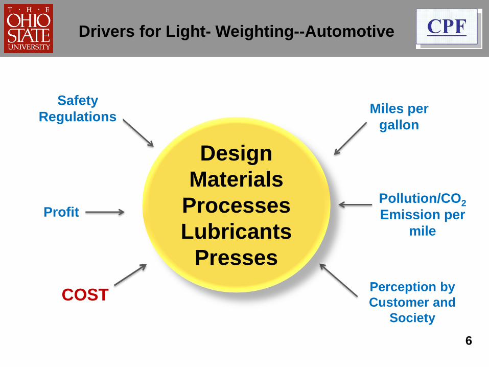
Pollution/CO2
Emission per
mile
Perception by
Customer and
Society
Miles per
gallon
Profit
Drivers for Light- Weighting--Automotive
Design
Materials
Processes
Lubricants
Presses
COST
Safety
Regulations
6
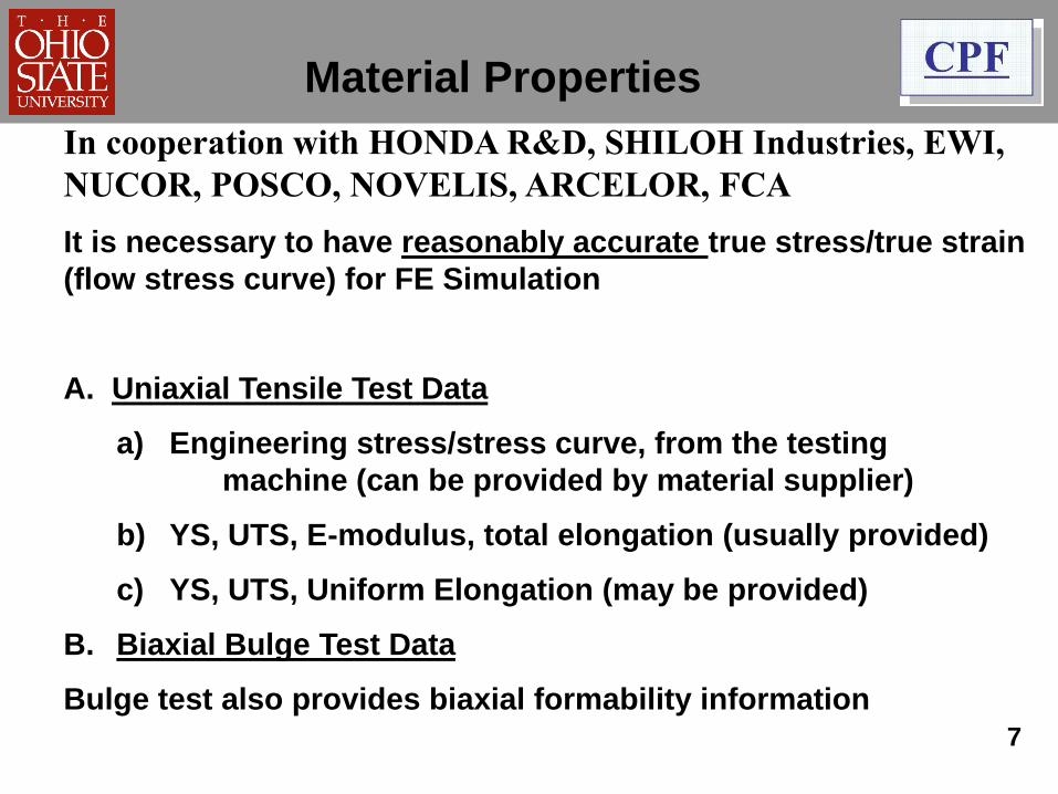
Material Properties
In cooperation with HONDA R&D, SHILOH Industries, EWI,
NUCOR, POSCO, NOVELIS, ARCELOR, FCA
It is necessary to have reasonably accurate true stress/true strain
(flow stress curve) for FE Simulation
A. Uniaxial Tensile Test Data
a) Engineering stress/stress curve, from the testing
machine (can be provided by material supplier)
b) YS, UTS, E-modulus, total elongation (usually provided)
c) YS, UTS, Uniform Elongation (may be provided)
B. Biaxial Bulge Test Data
Bulge test also provides biaxial formability information
7
8
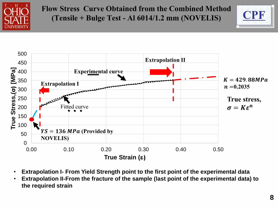
Flow Stress Curve Obtained from the Combined Method
(Tensile + Bulge Test - Al 6014/1.2 mm (NOVELIS)
0
50
100
150
200
250
300
350
400
450
500
0.00 0.10 0.20 0.30 0.40 0.50
Tru
e S
tress
,(σ)
[MP
a]
True Strain (ε)
𝑲 = 𝟒𝟐𝟗. 𝟖𝟖𝑴𝑷𝒂𝒏 =0.2035
𝒀𝑺 = 𝟏𝟑𝟔𝑴𝑷𝒂 (Provided by
NOVELIS)
Extrapolation I
Extrapolation II
Fitted curve
Experimental curve
• Extrapolation I- From Yield Strength point to the first point of the experimental data
• Extrapolation II-From the fracture of the sample (last point of the experimental data) to
the required strain
True stress,
𝝈 = 𝑲𝜺𝒏
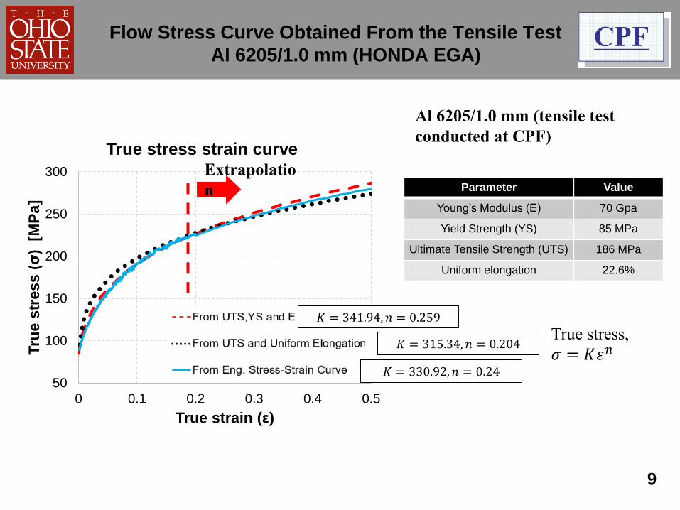
50
100
150
200
250
300
0 0.1 0.2 0.3 0.4 0.5
Tru
e s
tress (
σ)
[MP
a]
True strain (ε)
True stress strain curve
9
Parameter Value
Young’s Modulus (E) 70 Gpa
Yield Strength (YS) 85 MPa
Ultimate Tensile Strength (UTS) 186 MPa
Uniform elongation 22.6%
Flow Stress Curve Obtained From the Tensile Test
Al 6205/1.0 mm (HONDA EGA)
Al 6205/1.0 mm (tensile test
conducted at CPF)
Extrapolatio
n
𝐾 = 341.94, 𝑛 = 0.259
𝐾 = 315.34, 𝑛 = 0.204
𝐾 = 330.92, 𝑛 = 0.24
True stress,
𝜎 = 𝐾𝜀𝑛
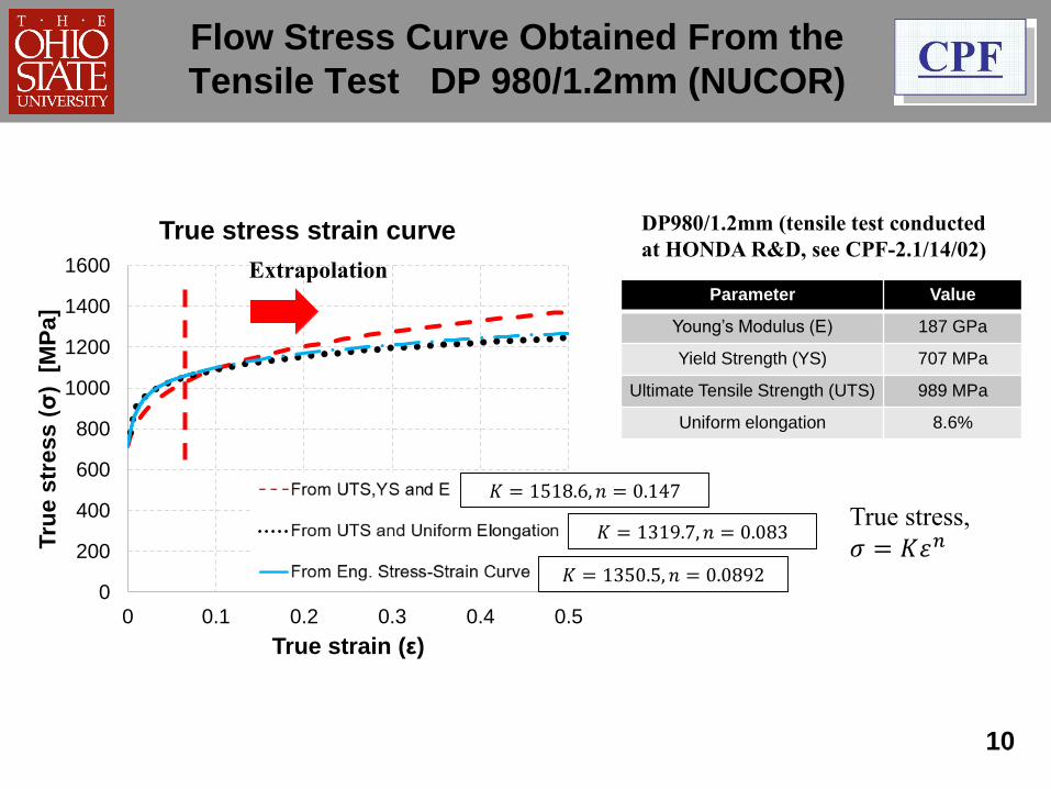
0
200
400
600
800
1000
1200
1400
1600
0 0.1 0.2 0.3 0.4 0.5
Tru
e s
tress (
σ)
[MP
a]
True strain (ε)
True stress strain curve
10
Flow Stress Curve Obtained From the
Tensile Test DP 980/1.2mm (NUCOR)
Parameter Value
Young’s Modulus (E) 187 GPa
Yield Strength (YS) 707 MPa
Ultimate Tensile Strength (UTS) 989 MPa
Uniform elongation 8.6%
DP980/1.2mm (tensile test conducted
at HONDA R&D, see CPF-2.1/14/02)Extrapolation
𝐾 = 1518.6, 𝑛 = 0.147
𝐾 = 1319.7, 𝑛 = 0.083
𝐾 = 1350.5, 𝑛 = 0.0892
True stress,
𝜎 = 𝐾𝜀𝑛
FRICTION/LUBRICATION
In cooperation with AFTON Chemical, EWI, HOUGHTON
International, QUAKER Chemical, SHILOH Industries,
IRMCO, HYSON Solutions
• The Cup Draw Test is well accepted for the evaluation of
lubricants/ forming speed and temperatures are important
• Tests are conducted (a) at EWI (160 ton Hydraulic Press and
CDT Tooling, and (b) at HYSON (300 ton Servo Press and
IRMCO iTool)
• For the lubricants and materials (Al and AHSS) tested,
friction seems to decrease with increasing drawing speed.
However, the effect of Blank Holder Force (BHF) variation at
various ram speeds may be a factor11
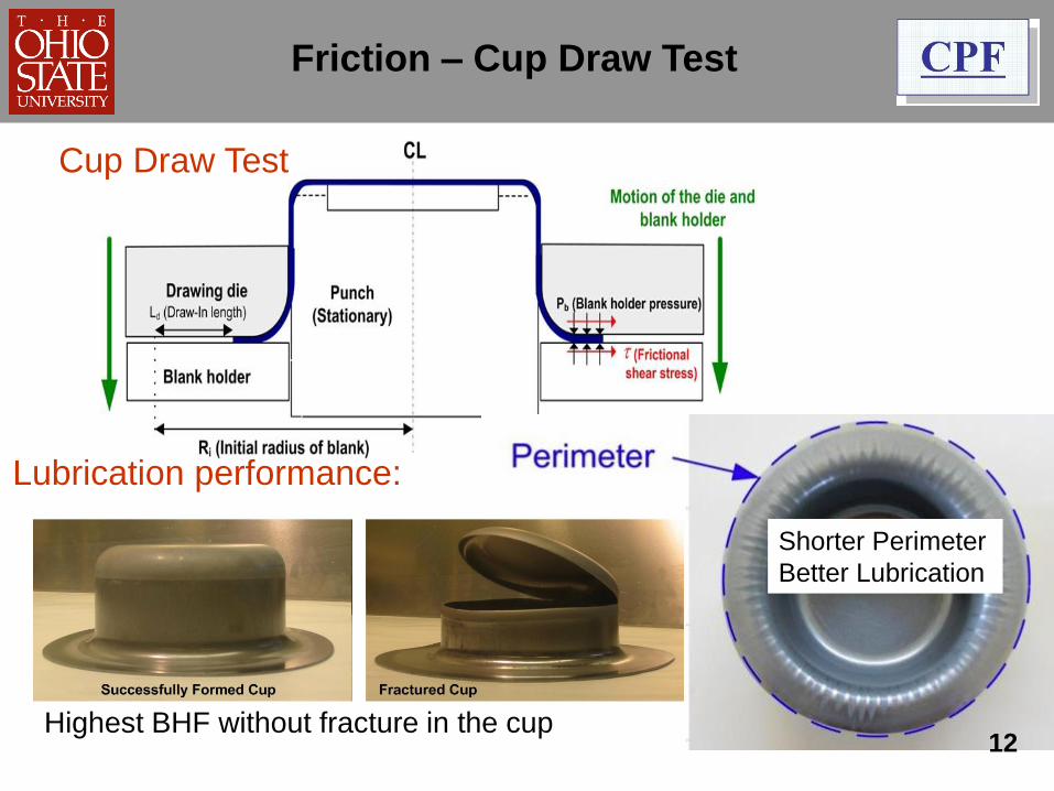
Friction – Cup Draw Test
Shorter Perimeter
Better Lubrication
Highest BHF without fracture in the cup
Cup Draw Test
Lubrication performance:
12
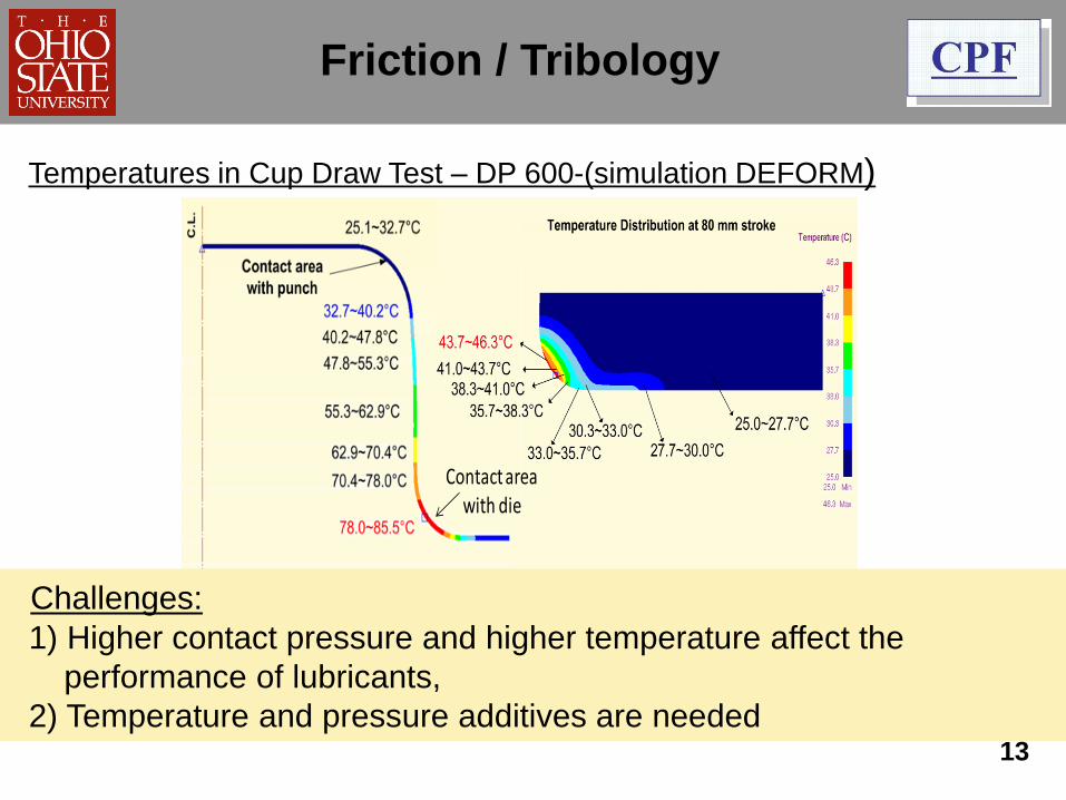
Friction / Tribology
Temperatures in Cup Draw Test – DP 600-(simulation DEFORM)
Contact area with die
Challenges:
1) Higher contact pressure and higher temperature affect the
performance of lubricants,
2) Temperature and pressure additives are needed13
Deep Drawing in a 300t Servo Press with
Servo Hydraulic Cushion
In cooperation with AIDA, SHILOH, HONDA-EGA,
BATESVILLE, ESI, HYSON
• With or without spacers/advances
• Elimination or modification of draw beads
• Use of servo hydraulic cushion (BHF variable with
stroke, vibrating BHF, change of BHF between stroke)
• Use of servo press capabilities (slow down before
deformation, attach/detach, coining)
14
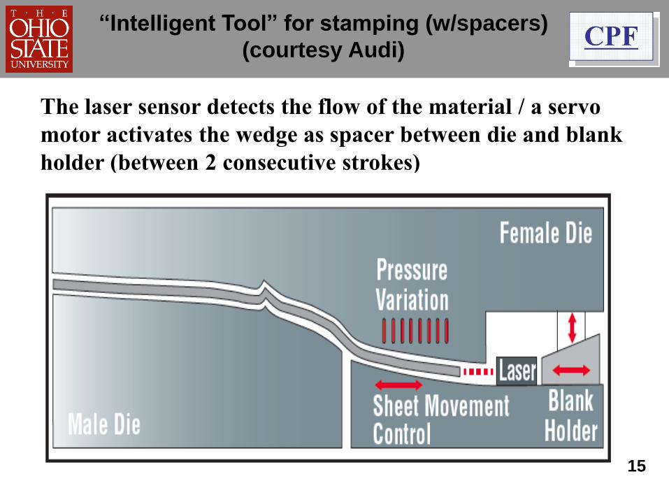
“Intelligent Tool” for stamping (w/spacers)
(courtesy Audi)
The laser sensor detects the flow of the material / a servo
motor activates the wedge as spacer between die and blank
holder (between 2 consecutive strokes)
15
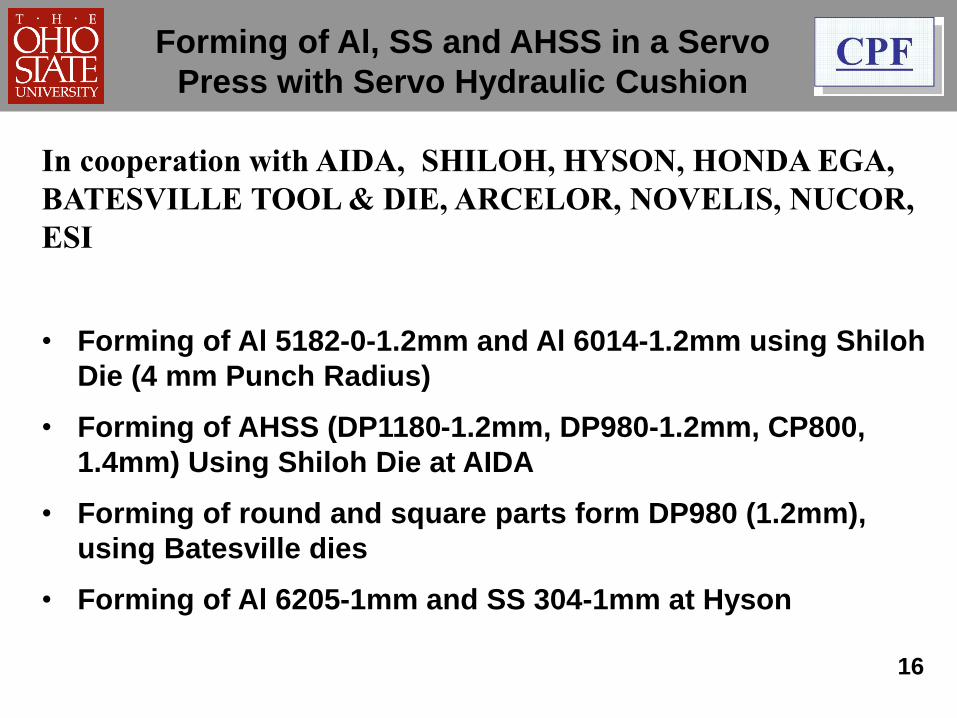
Forming of Al, SS and AHSS in a Servo
Press with Servo Hydraulic Cushion
In cooperation with AIDA, SHILOH, HYSON, HONDA EGA,
BATESVILLE TOOL & DIE, ARCELOR, NOVELIS, NUCOR,
ESI
• Forming of Al 5182-0-1.2mm and Al 6014-1.2mm using Shiloh
Die (4 mm Punch Radius)
• Forming of AHSS (DP1180-1.2mm, DP980-1.2mm, CP800,
1.4mm) Using Shiloh Die at AIDA
• Forming of round and square parts form DP980 (1.2mm),
using Batesville dies
• Forming of Al 6205-1mm and SS 304-1mm at Hyson
16
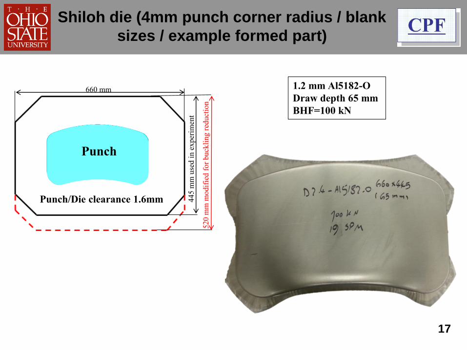
17
Punch
445 m
m u
sed i
n e
xper
imen
t
520 m
m m
odif
ied f
or
buck
ling r
educt
ion
660 mm 1.2 mm Al5182-O
Draw depth 65 mm
BHF=100 kN
Shiloh die (4mm punch corner radius / blank
sizes / example formed part)
Punch/Die clearance 1.6mm
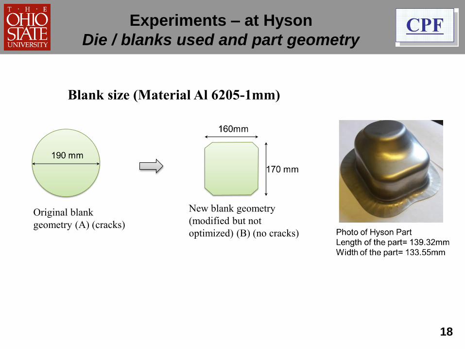
18
Original blank
geometry (A) (cracks)
New blank geometry
(modified but not
optimized) (B) (no cracks)
Blank size (Material Al 6205-1mm)
Experiments – at Hyson
Die / blanks used and part geometry
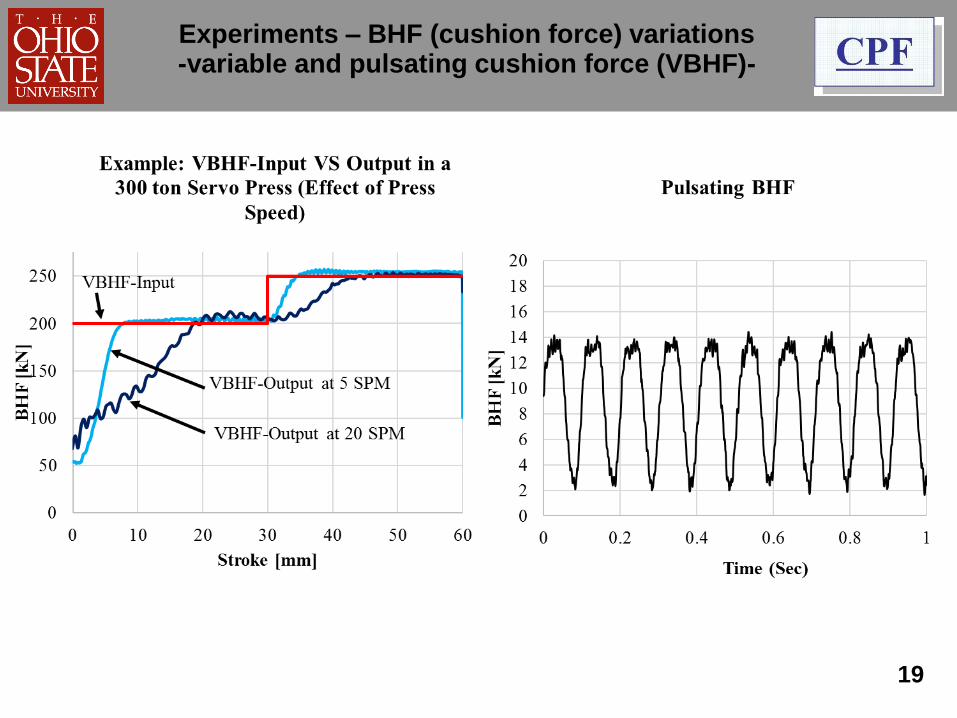
19
Experiments – BHF (cushion force) variations-variable and pulsating cushion force (VBHF)-
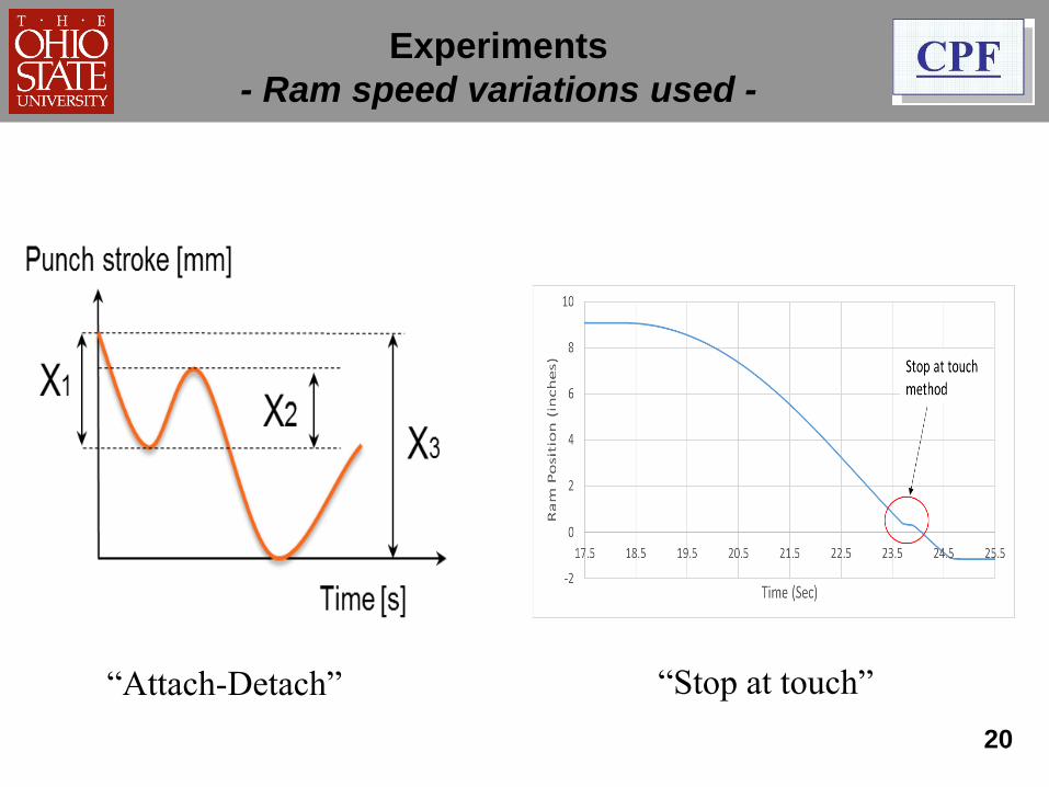
20
Experiments
- Ram speed variations used -
“Attach-Detach” “Stop at touch”
Forming in a servo press with servo hydraulic cushion
Conclusions / Observations
• Part size / geometry needs to be optimized (using simulation)
to reduce BHF and increase draw depth
• Increasing draw speed and attach/detach motion of the press
ram, appears to improve drawability slightly
(lubrication/BHF)
• As expected, cushion force (BHF) output is affected by press
speed (SPM)
• Work is in progress to (a) optimize blank size, ram motion
and BHF (cushion force) during stroke, for selected parts
and (b) develop guidelines
21
• Work is in progress to develop two courses for forming
various materials, for industry
– Principles and Applications of mechanical Servo
Drive Presses
– Principles and Applications of Servo Hydraulic
Cushions
• These courses will also cover the effects of (a) materials,
(b) lubrication, (c) blank shape, size and thicknesses, (d)
machine characteristics (productivity-SPM, force vs
stroke, energy vs stroke and speed), (e) various ram
speed motions and (f) various cushion force (BHF)
applications
22
Forming in a servo press with servo hydraulic cushion
In cooperation with Hyson, Shiloh and others
• Depending upon material and geometry, 4 to 6 die cuts
may be necessary during tryout. Can we reduce these?
• Various theoretical models (Yoshida and others) have
been developed. However,
(a) In some cases, the models cannot predict
springback accurately, and
(b) The models require large number of parameters that
are expensive to determine experimentally
• E-modulus is the most important parameter that affects
springback, it varies with strain and is difficult to
measure accurately
• A new simple “inverse analysis” method is being
developed at CPF
23
Springback in Forming AHSSin cooperation with Aida, Shiloh and Batesville
Examples : U-bending (DP 590 – 1.4mm, Al 5182-O –
1.2mm, Al 6014, 1.2mm) and Z-bending (DP 980 – 1.14mm)
Objective : Develop guidelines to predict springback using
FE simulation and experiment
Inverse Analysis: A constant apparent E value, for a given
material and bending process is determined by measuring
springback in experiments and comparing it with
simulations. This method is essentially similar to the
method used in industry for die try-out
24
Springback in Forming AHSS- Inverse Analysis -
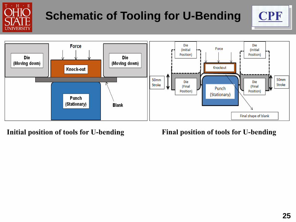
Initial position of tools for U-bending Final position of tools for U-bending
25
Schematic of Tooling for U-Bending
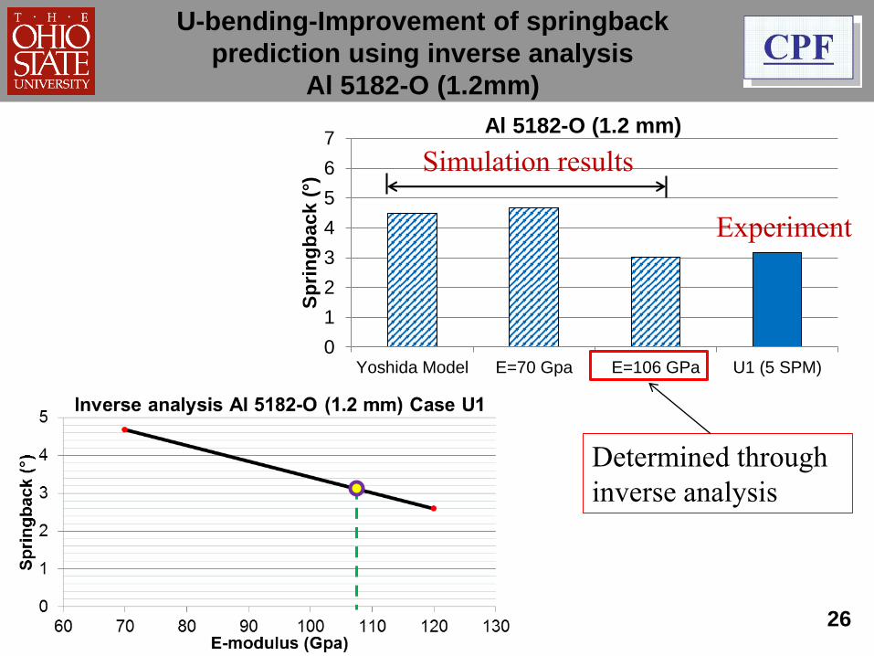
0
1
2
3
4
5
6
7
Yoshida Model E=70 Gpa E=106 GPa U1 (5 SPM)
Sp
rin
gb
ac
k (
°)
Al 5182-O (1.2 mm)
26
Determined through
inverse analysis
Simulation results
Experiment
U-bending-Improvement of springback
prediction using inverse analysis
Al 5182-O (1.2mm)
27
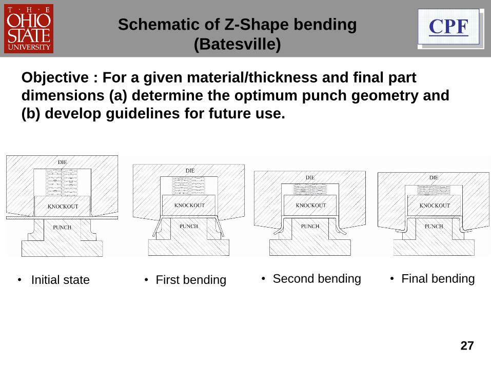
• Initial state • Final bending• First bending • Second bending
Schematic of Z-Shape bending
(Batesville)
Objective : For a given material/thickness and final part
dimensions (a) determine the optimum punch geometry and
(b) develop guidelines for future use.
28
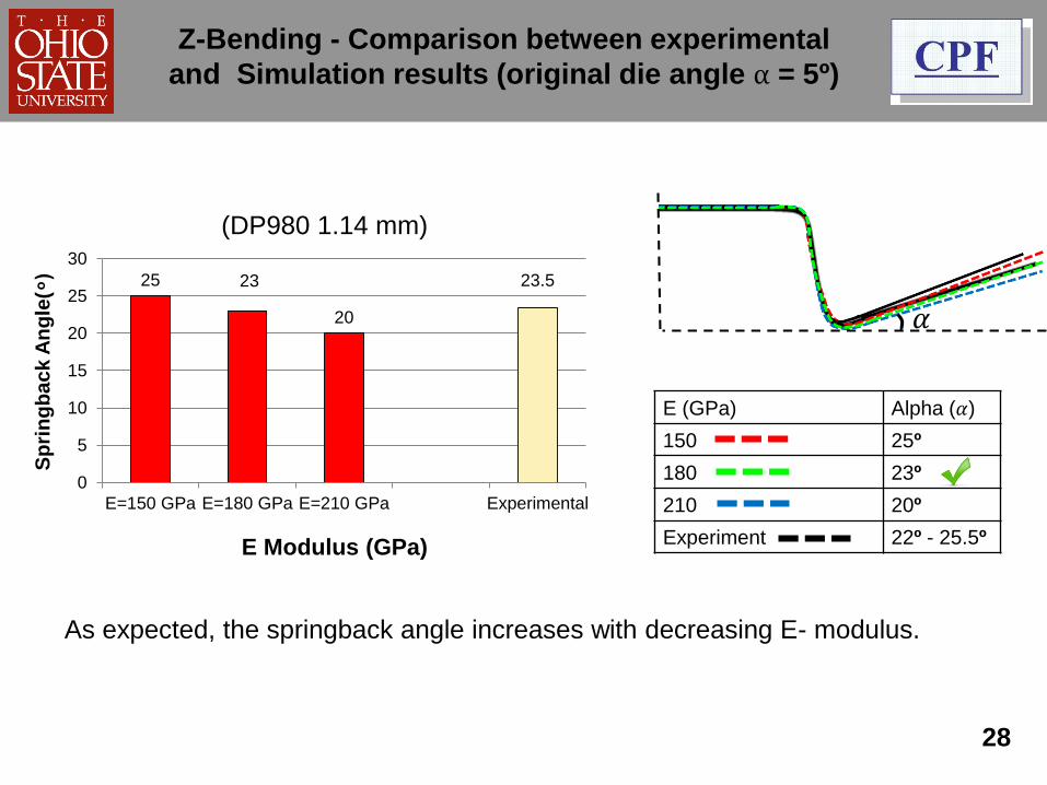
𝛼
E (GPa) Alpha (𝛼)
150 25º
180 23º
210 20º
Experiment 22º - 25.5º
As expected, the springback angle increases with decreasing E- modulus.
(DP980 1.14 mm)
Z-Bending - Comparison between experimental
and Simulation results (original die angle α = 5º)
25 23
20
23.5
0
5
10
15
20
25
30
E=150 GPa E=180 GPa E=210 GPa Experimental
Sp
rin
gb
ac
k A
ng
le(
)
E Modulus (GPa)
Materials:
• Need for reliable true stress vs true strain curve, if possible for biaxial
deformation
• Information on forming of new materials (DP980, DP1180, TWIP, TRIP
steels, etc) including cost and availability
Friction/Lubrication:
• CDT and other tests/effect of temperature and forming speed
Deep Drawing:
• Spacers? / drawbeads? / use of servo hydraulic cushions / variable
BHF / multiple point cushions
Servo Press:
• Productivity/Attach-Detach/Ram speed before and during
forming/dwell/pendulum motion
29
Summary/Future Trends
Springback in forming AHSS:
• Theoretical methods vs inverse analysis / applications
Training / Education :
• Training for effective use of new technologies (FE simulations, servo
presses, servo hydraulic cushions, new materials and lubrications,
hot stamping, warm/hot forming of heat treatable Al alloys, etc)
30
Summary/Future Trends
Contact Information
For more information, please contact:
Dr. Taylan Altan ([email protected])
Center for Precision Forming – CPF
339 Baker Systems,1971 Neil Ave,
Columbus, OH-43210
Ph - 614-292-5063
Non-proprietary information can be found at web
site: https://ercnsm.osu.edu
31
Related Documents