New demodulation filter in digital phase rotation beamforming Fabio Kurt Schneider a , Yang Mo Yoo a , Anup Agarwal a , Liang Mong Koh b , Yongmin Kim a, * a Image Computing Systems Laboratory, Departments of Electrical Engineering and Bioengineering, University of Washington, Seattle, WA 98195-2500, United States b School of Electrical and Electronic Engineering, Nanyang Technological University, Singapore 639798, Singapore Received 27 December 2005; received in revised form 7 February 2006; accepted 8 February 2006 Available online 6 March 2006 Abstract In this paper, we present a new quadrature demodulation filter to reduce hardware complexity in digital phase rotation beamforming. Due to its low sensitivity to phase delay errors, digital quadrature demodulation is commonly used in ultrasound machines. However, since it requires two lowpass filters for each channel to remove harmonics, the direct use of conventional finite impulse response (FIR) filters in ultrasound machines is computationally expensive and burdensome. In our new method, an efficient multi-stage uniform coef- ficient (MSUC) filter is utilized to remove harmonic components in phase rotation beamforming. In comparison with the directly imple- mented FIR (DI-FIR) and the previously-proposed signed-power-of-two FIR (SPOT-FIR) lowpass filters, the proposed MSUC filter reduces the necessary hardware resources by 93.9% and 83.9%, respectively. In simulation, the MSUC filter shows a negligible degrada- tion in image quality. The proposed method resulted in comparable spatial and contrast resolution to the DI-FIR approach in the phan- tom study. These preliminary results indicate that the proposed quadrature demodulation filtering method could significantly reduce the hardware complexity in phase rotation beamforming while maintaining comparable image quality. Ó 2006 Elsevier B.V. All rights reserved. Keywords: Ultrasonic imaging; Beamforming; Phase rotation beamforming; Quadrature demodulation filter; Hardware complexity 1. Introduction The adoption of digital receive beamforming (DRBF) techniques based on dynamic focusing has greatly improved the ultrasound image quality in the last few decades [1]. In the DRBF, the enhanced time delay accuracy in digital pro- cessing provides higher signal-to-noise ratios (SNR) and better spatial resolution. In addition, the DRBF’s flexibility has enabled new imaging techniques (e.g., dynamic aperture and multi-beam) [2]. However, the DRBF significantly increases the computational complexity since it requires fast analog-to-digital converters (ADC) and front-end digital circuitries running at a high clock frequency. To alleviate the high-frequency requirement in ADCs and front-end cir- cuitries, interpolation beamforming (IBF) and phase rota- tion beamforming (PRBF) methods have been developed [2–4] and are commonly used in ultrasound machines [5]. However, IBF and PRBF methods require many computa- tionally-expensive interpolation and demodulation filters, respectively. Thus, this high computational requirement makes the development of ultrasound machines with large channel counts (e.g., for 3D ultrasound systems [6]) or very low-end machines (e.g., handheld [7]) challenging. Various beamforming techniques, such as pipelined- sampled-delay-focusing (PSDF) [8], sigma-delta oversam- pled (SDO) [5] and direct I/Q [9], have been developed for further reducing the hardware burden in the DRBF. The PSDF technique relies on non-uniform sampling of the sig- nals coming from the different receive channels to compen- sate for time delay differences in dynamic receive focusing [8]. While the PSDF succeeds in lowering the hardware complexity, the control of ADCs for non-uniform sampling 0041-624X/$ - see front matter Ó 2006 Elsevier B.V. All rights reserved. doi:10.1016/j.ultras.2006.02.004 * Corresponding author. Tel.: +1 206 685 2271; fax: +1 206 543 3852. E-mail address: [email protected] (Y. Kim). www.elsevier.com/locate/ultras Ultrasonics 44 (2006) 265–271

Welcome message from author
This document is posted to help you gain knowledge. Please leave a comment to let me know what you think about it! Share it to your friends and learn new things together.
Transcript
www.elsevier.com/locate/ultras
Ultrasonics 44 (2006) 265–271
New demodulation filter in digital phase rotation beamforming
Fabio Kurt Schneider a, Yang Mo Yoo a, Anup Agarwal a,Liang Mong Koh b, Yongmin Kim a,*
a Image Computing Systems Laboratory, Departments of Electrical Engineering and Bioengineering, University of Washington, Seattle,
WA 98195-2500, United Statesb School of Electrical and Electronic Engineering, Nanyang Technological University, Singapore 639798, Singapore
Received 27 December 2005; received in revised form 7 February 2006; accepted 8 February 2006Available online 6 March 2006
Abstract
In this paper, we present a new quadrature demodulation filter to reduce hardware complexity in digital phase rotation beamforming.Due to its low sensitivity to phase delay errors, digital quadrature demodulation is commonly used in ultrasound machines. However,since it requires two lowpass filters for each channel to remove harmonics, the direct use of conventional finite impulse response (FIR)filters in ultrasound machines is computationally expensive and burdensome. In our new method, an efficient multi-stage uniform coef-ficient (MSUC) filter is utilized to remove harmonic components in phase rotation beamforming. In comparison with the directly imple-mented FIR (DI-FIR) and the previously-proposed signed-power-of-two FIR (SPOT-FIR) lowpass filters, the proposed MSUC filterreduces the necessary hardware resources by 93.9% and 83.9%, respectively. In simulation, the MSUC filter shows a negligible degrada-tion in image quality. The proposed method resulted in comparable spatial and contrast resolution to the DI-FIR approach in the phan-tom study. These preliminary results indicate that the proposed quadrature demodulation filtering method could significantly reduce thehardware complexity in phase rotation beamforming while maintaining comparable image quality.� 2006 Elsevier B.V. All rights reserved.
Keywords: Ultrasonic imaging; Beamforming; Phase rotation beamforming; Quadrature demodulation filter; Hardware complexity
1. Introduction
The adoption of digital receive beamforming (DRBF)techniques based on dynamic focusing has greatly improvedthe ultrasound image quality in the last few decades [1]. Inthe DRBF, the enhanced time delay accuracy in digital pro-cessing provides higher signal-to-noise ratios (SNR) andbetter spatial resolution. In addition, the DRBF’s flexibilityhas enabled new imaging techniques (e.g., dynamic apertureand multi-beam) [2]. However, the DRBF significantlyincreases the computational complexity since it requires fastanalog-to-digital converters (ADC) and front-end digitalcircuitries running at a high clock frequency. To alleviatethe high-frequency requirement in ADCs and front-end cir-
0041-624X/$ - see front matter � 2006 Elsevier B.V. All rights reserved.
doi:10.1016/j.ultras.2006.02.004
* Corresponding author. Tel.: +1 206 685 2271; fax: +1 206 543 3852.E-mail address: [email protected] (Y. Kim).
cuitries, interpolation beamforming (IBF) and phase rota-tion beamforming (PRBF) methods have been developed[2–4] and are commonly used in ultrasound machines [5].However, IBF and PRBF methods require many computa-tionally-expensive interpolation and demodulation filters,respectively. Thus, this high computational requirementmakes the development of ultrasound machines with largechannel counts (e.g., for 3D ultrasound systems [6]) or verylow-end machines (e.g., handheld [7]) challenging.
Various beamforming techniques, such as pipelined-sampled-delay-focusing (PSDF) [8], sigma-delta oversam-pled (SDO) [5] and direct I/Q [9], have been developed forfurther reducing the hardware burden in the DRBF. ThePSDF technique relies on non-uniform sampling of the sig-nals coming from the different receive channels to compen-sate for time delay differences in dynamic receive focusing[8]. While the PSDF succeeds in lowering the hardwarecomplexity, the control of ADCs for non-uniform sampling
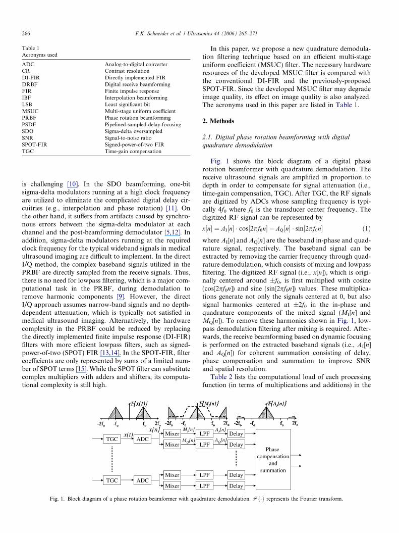
Table 1Acronyms used
ADC Analog-to-digital converterCR Contrast resolutionDI-FIR Directly implemented FIRDRBF Digital receive beamformingFIR Finite impulse responseIBF Interpolation beamformingLSB Least significant bitMSUC Multi-stage uniform coefficientPRBF Phase rotation beamformingPSDF Pipelined-sampled-delay-focusingSDO Sigma-delta oversampledSNR Signal-to-noise ratioSPOT-FIR Signed-power-of-two FIRTGC Time-gain compensation
266 F.K. Schneider et al. / Ultrasonics 44 (2006) 265–271
is challenging [10]. In the SDO beamforming, one-bitsigma-delta modulators running at a high clock frequencyare utilized to eliminate the complicated digital delay cir-cuitries (e.g., interpolation and phase rotation) [11]. Onthe other hand, it suffers from artifacts caused by synchro-nous errors between the sigma-delta modulator at eachchannel and the post-beamforming demodulator [5,12]. Inaddition, sigma-delta modulators running at the requiredclock frequency for the typical wideband signals in medicalultrasound imaging are difficult to implement. In the directI/Q method, the complex baseband signals utilized in thePRBF are directly sampled from the receive signals. Thus,there is no need for lowpass filtering, which is a major com-putational task in the PRBF, during demodulation toremove harmonic components [9]. However, the directI/Q approach assumes narrow-band signals and no depth-dependent attenuation, which is typically not satisfied inmedical ultrasound imaging. Alternatively, the hardwarecomplexity in the PRBF could be reduced by replacingthe directly implemented finite impulse response (DI-FIR)filters with more efficient lowpass filters, such as signed-power-of-two (SPOT) FIR [13,14]. In the SPOT-FIR, filtercoefficients are only represented by sums of a limited num-ber of SPOT terms [15]. While the SPOT filter can substitutecomplex multipliers with adders and shifters, its computa-tional complexity is still high.
Fig. 1. Block diagram of a phase rotation beamformer with quad
In this paper, we propose a new quadrature demodula-tion filtering technique based on an efficient multi-stageuniform coefficient (MSUC) filter. The necessary hardwareresources of the developed MSUC filter is compared withthe conventional DI-FIR and the previously-proposedSPOT-FIR. Since the developed MSUC filter may degradeimage quality, its effect on image quality is also analyzed.The acronyms used in this paper are listed in Table 1.
2. Methods
2.1. Digital phase rotation beamforming with digital
quadrature demodulation
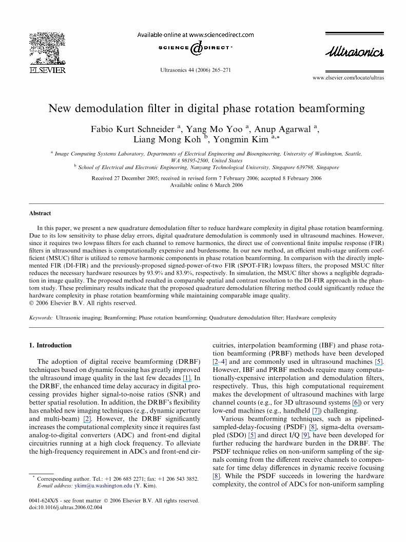
Fig. 1 shows the block diagram of a digital phaserotation beamformer with quadrature demodulation. Thereceive ultrasound signals are amplified in proportion todepth in order to compensate for signal attenuation (i.e.,time-gain compensation, TGC). After TGC, the RF signalsare digitized by ADCs whose sampling frequency is typi-cally 4f0 where f0 is the transducer center frequency. Thedigitized RF signal can be represented by
x½n� ¼ AI½n� � cos½2pf0n� � AQ½n� � sin½2pf0n� ð1Þwhere AI[n] and AQ[n] are the baseband in-phase and quad-rature signal, respectively. The baseband signal can beextracted by removing the carrier frequency through quad-rature demodulation, which consists of mixing and lowpassfiltering. The digitized RF signal (i.e., x[n]), which is origi-nally centered around ±f0, is first multiplied with cosine(cos[2pf0n]) and sine (sin[2pf0n]) values. These multiplica-tions generate not only the signals centered at 0, but alsosignal harmonics centered at ±2f0 in the in-phase andquadrature components of the mixed signal (MI[n] andMQ[n]). To remove these harmonics shown in Fig. 1, low-pass demodulation filtering after mixing is required. After-wards, the receive beamforming based on dynamic focusingis performed on the extracted baseband signals (i.e., AI[n]and AQ[n]) for coherent summation consisting of delay,phase compensation and summation to improve SNRand spatial resolution.
Table 2 lists the computational load of each processingfunction (in terms of multiplications and additions) in the
rature demodulation. Ff�g represents the Fourier transform.
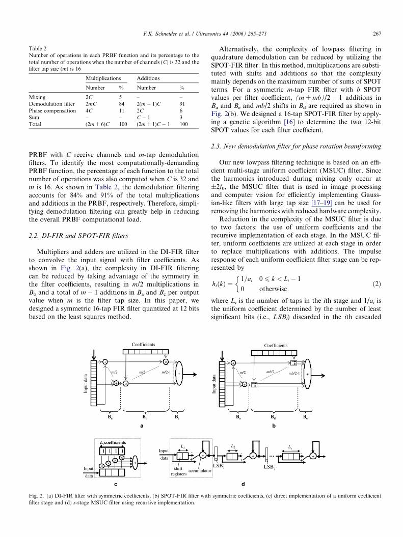
Table 2Number of operations in each PRBF function and its percentage to thetotal number of operations when the number of channels (C) is 32 and thefilter tap size (m) is 16
Multiplications Additions
Number % Number %
Mixing 2C 5 – –Demodulation filter 2mC 84 2(m � 1)C 91Phase compensation 4C 11 2C 6Sum – – C � 1 3Total (2m + 6)C 100 (2m + 1)C � 1 100
F.K. Schneider et al. / Ultrasonics 44 (2006) 265–271 267
PRBF with C receive channels and m-tap demodulationfilters. To identify the most computationally-demandingPRBF function, the percentage of each function to the totalnumber of operations was also computed when C is 32 andm is 16. As shown in Table 2, the demodulation filteringaccounts for 84% and 91% of the total multiplicationsand additions in the PRBF, respectively. Therefore, simpli-fying demodulation filtering can greatly help in reducingthe overall PRBF computational load.
2.2. DI-FIR and SPOT-FIR filters
Multipliers and adders are utilized in the DI-FIR filterto convolve the input signal with filter coefficients. Asshown in Fig. 2(a), the complexity in DI-FIR filteringcan be reduced by taking advantage of the symmetry inthe filter coefficients, resulting in m/2 multiplications inBb and a total of m � 1 additions in Ba and Bc per outputvalue when m is the filter tap size. In this paper, wedesigned a symmetric 16-tap FIR filter quantized at 12 bitsbased on the least squares method.
+
+
Coefficients
+
×
×
m/2 m/2 m/2-1
Inpu
t dat
a
Ba Bb BcBa Bb Bc
1111 1111
+×
××
×
L1
Li coefficientsLi coefficients
Input
data
-
++
shift registers
Input
data
accumulato
a
c
Fig. 2. (a) DI-FIR filter with symmetric coefficients, (b) SPOT-FIR filter withfilter stage and (d) s-stage MSUC filter using recursive implementation.
Alternatively, the complexity of lowpass filtering inquadrature demodulation can be reduced by utilizing theSPOT-FIR filter. In this method, multiplications are substi-tuted with shifts and additions so that the complexitymainly depends on the maximum number of sums of SPOTterms. For a symmetric m-tap FIR filter with b SPOTvalues per filter coefficient, (m + mb)/2 � 1 additions inBa and Be and mb/2 shifts in Bd are required as shown inFig. 2(b). We designed a 16-tap SPOT-FIR filter by apply-ing a genetic algorithm [16] to determine the two 12-bitSPOT values for each filter coefficient.
2.3. New demodulation filter for phase rotation beamforming
Our new lowpass filtering technique is based on an effi-cient multi-stage uniform coefficient (MSUC) filter. Sincethe harmonics introduced during mixing only occur at±2f0, the MSUC filter that is used in image processingand computer vision for efficiently implementing Gauss-ian-like filters with large tap size [17–19] can be used forremoving the harmonics with reduced hardware complexity.
Reduction in the complexity of the MSUC filter is dueto two factors: the use of uniform coefficients and therecursive implementation of each stage. In the MSUC fil-ter, uniform coefficients are utilized at each stage in orderto replace multiplications with additions. The impulseresponse of each uniform coefficient filter stage can be rep-resented by
hiðkÞ ¼1=ai 0 6 k < Li � 1
0 otherwise
�ð2Þ
where Li is the number of taps in the ith stage and 1/ai isthe uniform coefficient determined by the number of leastsignificant bits (i.e., LSBi) discarded in the ith cascaded
+
+
+m/2 mb/2 mb/2-1
Coefficients
Inpu
t dat
a
Ba Bd BeBa Bd Be
LSB1
L2
-
++
LSB2
Ls
-
++
r
d
b
symmetric coefficients, (c) direct implementation of a uniform coefficient
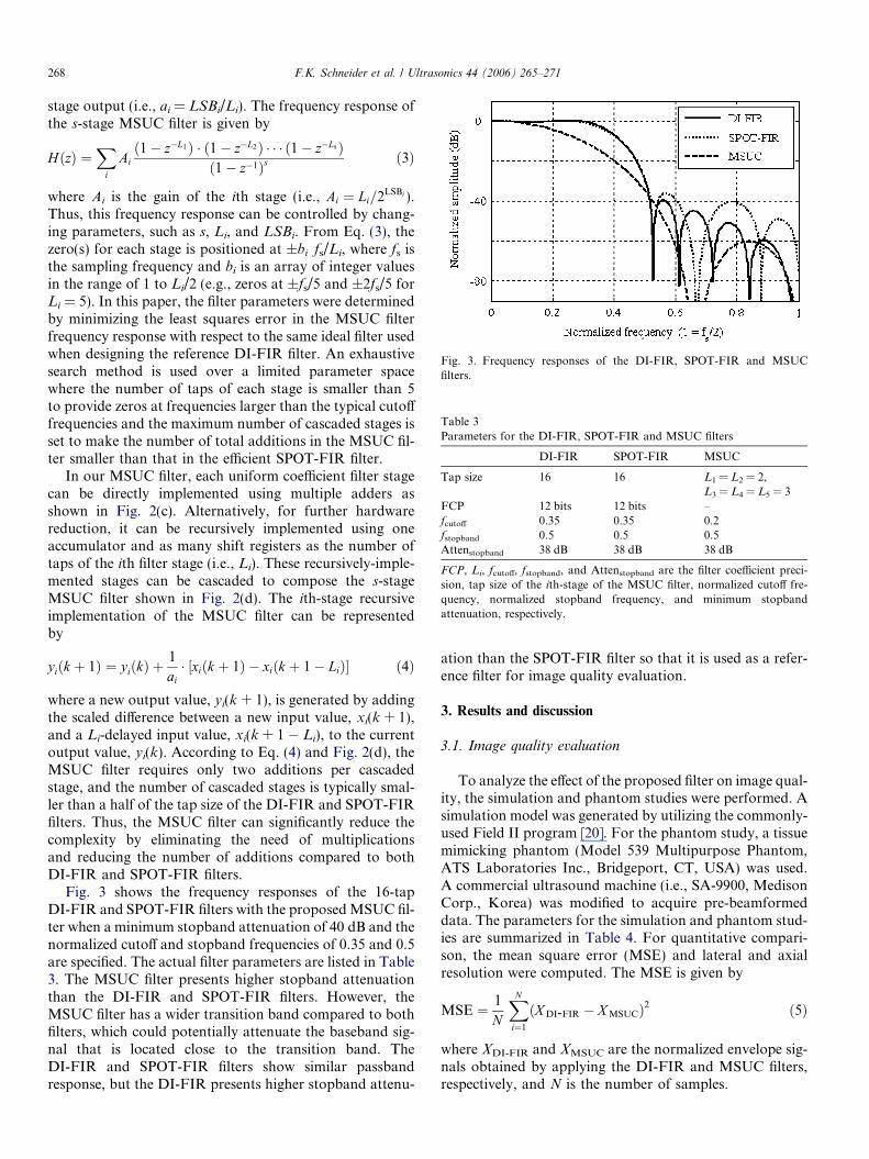
Fig. 3. Frequency responses of the DI-FIR, SPOT-FIR and MSUCfilters.
Table 3Parameters for the DI-FIR, SPOT-FIR and MSUC filters
DI-FIR SPOT-FIR MSUC
Tap size 16 16 L1 = L2 = 2,L3 = L4 = L5 = 3
FCP 12 bits 12 bits –fcutoff 0.35 0.35 0.2fstopband 0.5 0.5 0.5Attenstopband 38 dB 38 dB 38 dB
FCP, Li, fcutoff, fstopband, and Attenstopband are the filter coefficient preci-sion, tap size of the ith-stage of the MSUC filter, normalized cutoff fre-quency, normalized stopband frequency, and minimum stopbandattenuation, respectively.
268 F.K. Schneider et al. / Ultrasonics 44 (2006) 265–271
stage output (i.e., ai = LSBi/Li). The frequency response ofthe s-stage MSUC filter is given by
HðzÞ ¼X
i
Aið1� z�L1Þ � ð1� z�L2Þ � � � ð1� z�LsÞ
ð1� z�1Þs ð3Þ
where Ai is the gain of the ith stage (i.e., Ai ¼ Li=2LSBi ).Thus, this frequency response can be controlled by chang-ing parameters, such as s, Li, and LSBi. From Eq. (3), thezero(s) for each stage is positioned at ±bi Æ fs/Li, where fs isthe sampling frequency and bi is an array of integer valuesin the range of 1 to Li/2 (e.g., zeros at ±fs/5 and ±2fs/5 forLi = 5). In this paper, the filter parameters were determinedby minimizing the least squares error in the MSUC filterfrequency response with respect to the same ideal filter usedwhen designing the reference DI-FIR filter. An exhaustivesearch method is used over a limited parameter spacewhere the number of taps of each stage is smaller than 5to provide zeros at frequencies larger than the typical cutofffrequencies and the maximum number of cascaded stages isset to make the number of total additions in the MSUC fil-ter smaller than that in the efficient SPOT-FIR filter.
In our MSUC filter, each uniform coefficient filter stagecan be directly implemented using multiple adders asshown in Fig. 2(c). Alternatively, for further hardwarereduction, it can be recursively implemented using oneaccumulator and as many shift registers as the number oftaps of the ith filter stage (i.e., Li). These recursively-imple-mented stages can be cascaded to compose the s-stageMSUC filter shown in Fig. 2(d). The ith-stage recursiveimplementation of the MSUC filter can be representedby
yiðk þ 1Þ ¼ yiðkÞ þ1
ai� ½xiðk þ 1Þ � xiðk þ 1� LiÞ� ð4Þ
where a new output value, yi(k + 1), is generated by addingthe scaled difference between a new input value, xi(k + 1),and a Li-delayed input value, xi(k + 1 � Li), to the currentoutput value, yi(k). According to Eq. (4) and Fig. 2(d), theMSUC filter requires only two additions per cascadedstage, and the number of cascaded stages is typically smal-ler than a half of the tap size of the DI-FIR and SPOT-FIRfilters. Thus, the MSUC filter can significantly reduce thecomplexity by eliminating the need of multiplicationsand reducing the number of additions compared to bothDI-FIR and SPOT-FIR filters.
Fig. 3 shows the frequency responses of the 16-tapDI-FIR and SPOT-FIR filters with the proposed MSUC fil-ter when a minimum stopband attenuation of 40 dB and thenormalized cutoff and stopband frequencies of 0.35 and 0.5are specified. The actual filter parameters are listed in Table3. The MSUC filter presents higher stopband attenuationthan the DI-FIR and SPOT-FIR filters. However, theMSUC filter has a wider transition band compared to bothfilters, which could potentially attenuate the baseband sig-nal that is located close to the transition band. TheDI-FIR and SPOT-FIR filters show similar passbandresponse, but the DI-FIR presents higher stopband attenu-
ation than the SPOT-FIR filter so that it is used as a refer-ence filter for image quality evaluation.
3. Results and discussion
3.1. Image quality evaluation
To analyze the effect of the proposed filter on image qual-ity, the simulation and phantom studies were performed. Asimulation model was generated by utilizing the commonly-used Field II program [20]. For the phantom study, a tissuemimicking phantom (Model 539 Multipurpose Phantom,ATS Laboratories Inc., Bridgeport, CT, USA) was used.A commercial ultrasound machine (i.e., SA-9900, MedisonCorp., Korea) was modified to acquire pre-beamformeddata. The parameters for the simulation and phantom stud-ies are summarized in Table 4. For quantitative compari-son, the mean square error (MSE) and lateral and axialresolution were computed. The MSE is given by
MSE ¼ 1
N
XN
i¼1
ðX DI-FIR � X MSUCÞ2 ð5Þ
where XDI-FIR and XMSUC are the normalized envelope sig-nals obtained by applying the DI-FIR and MSUC filters,respectively, and N is the number of samples.
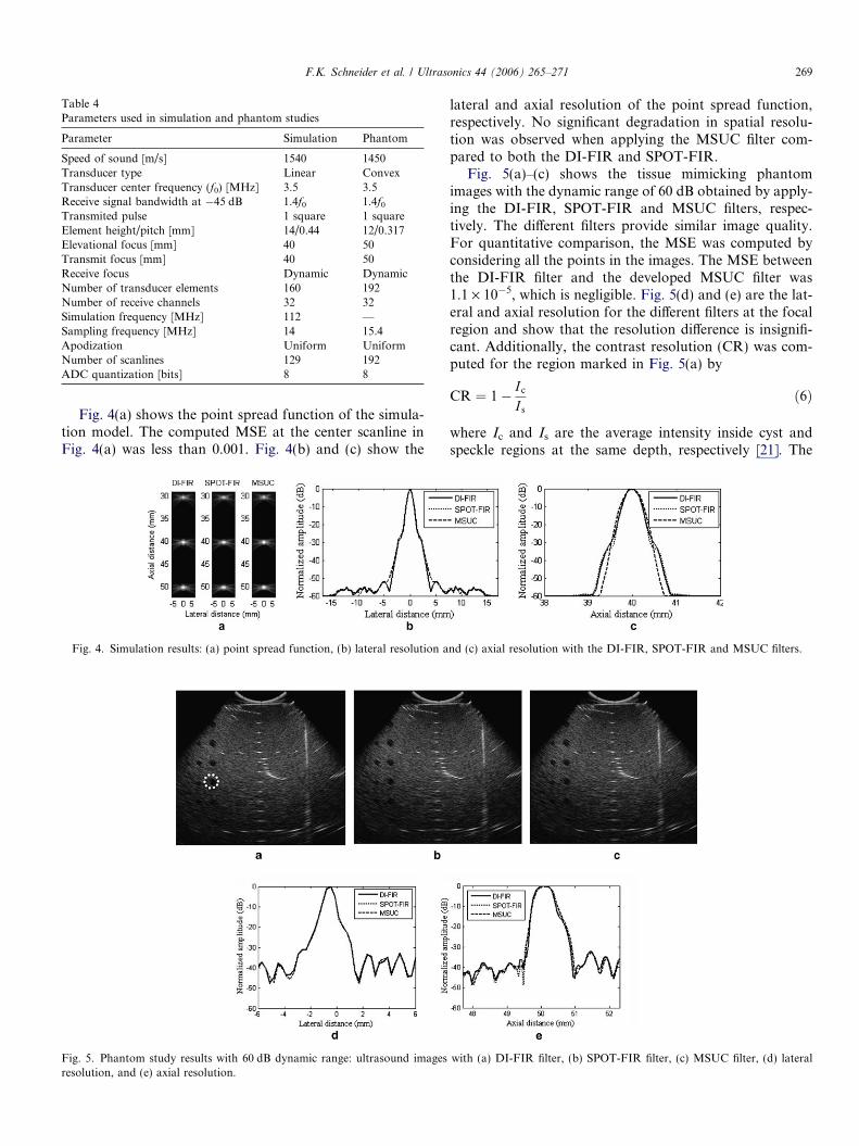
Table 4Parameters used in simulation and phantom studies
Parameter Simulation Phantom
Speed of sound [m/s] 1540 1450Transducer type Linear ConvexTransducer center frequency (f0) [MHz] 3.5 3.5Receive signal bandwidth at �45 dB 1.4f0 1.4f0
Transmited pulse 1 square 1 squareElement height/pitch [mm] 14/0.44 12/0.317Elevational focus [mm] 40 50Transmit focus [mm] 40 50Receive focus Dynamic DynamicNumber of transducer elements 160 192Number of receive channels 32 32Simulation frequency [MHz] 112 —Sampling frequency [MHz] 14 15.4Apodization Uniform UniformNumber of scanlines 129 192ADC quantization [bits] 8 8
F.K. Schneider et al. / Ultrasonics 44 (2006) 265–271 269
Fig. 4(a) shows the point spread function of the simula-tion model. The computed MSE at the center scanline inFig. 4(a) was less than 0.001. Fig. 4(b) and (c) show the
Fig. 5. Phantom study results with 60 dB dynamic range: ultrasound imagesresolution, and (e) axial resolution.
Fig. 4. Simulation results: (a) point spread function, (b) lateral resolution a
lateral and axial resolution of the point spread function,respectively. No significant degradation in spatial resolu-tion was observed when applying the MSUC filter com-pared to both the DI-FIR and SPOT-FIR.
Fig. 5(a)–(c) shows the tissue mimicking phantomimages with the dynamic range of 60 dB obtained by apply-ing the DI-FIR, SPOT-FIR and MSUC filters, respec-tively. The different filters provide similar image quality.For quantitative comparison, the MSE was computed byconsidering all the points in the images. The MSE betweenthe DI-FIR filter and the developed MSUC filter was1.1 · 10�5, which is negligible. Fig. 5(d) and (e) are the lat-eral and axial resolution for the different filters at the focalregion and show that the resolution difference is insignifi-cant. Additionally, the contrast resolution (CR) was com-puted for the region marked in Fig. 5(a) by
CR ¼ 1� Ic
I s
ð6Þ
where Ic and Is are the average intensity inside cyst andspeckle regions at the same depth, respectively [21]. The
with (a) DI-FIR filter, (b) SPOT-FIR filter, (c) MSUC filter, (d) lateral
nd (c) axial resolution with the DI-FIR, SPOT-FIR and MSUC filters.
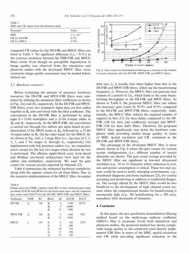
Table 5MSE and CR values from the phantom study
Parameter Value
MSE 1.1 · 10�5
CR for DI-FIR 0.732CR for MSUC 0.730
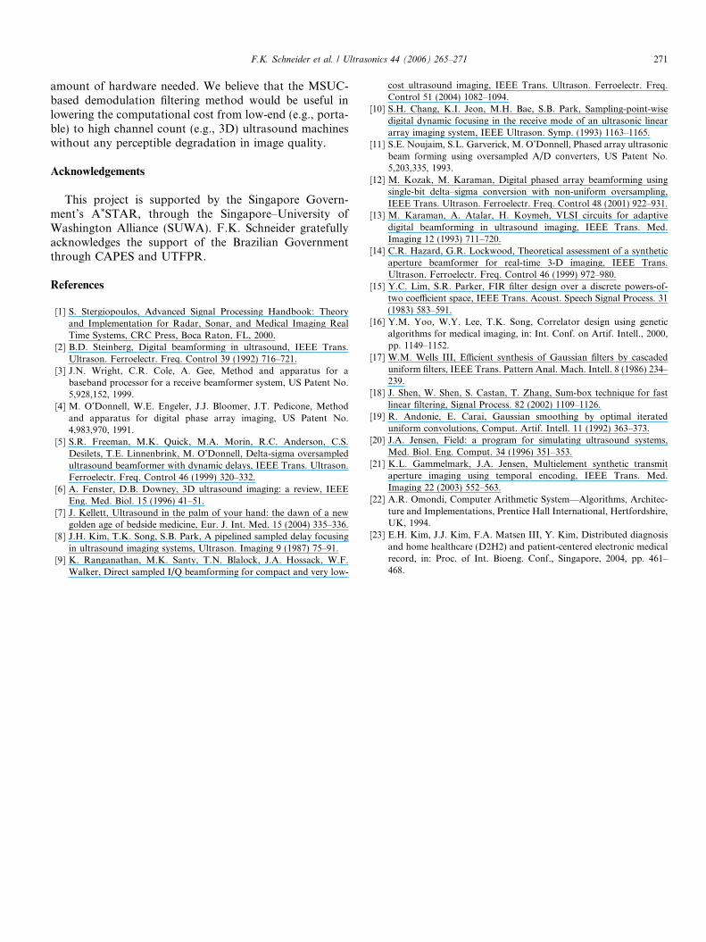
Fig. 6. Gate counts for demodulation filtering as a function of the numberof receive channels with the DI-FIR, SPOT-FIR and MSUC filters.
270 F.K. Schneider et al. / Ultrasonics 44 (2006) 265–271
computed CR values for the DI-FIR and MSUC filters arelisted in Table 5. No significant difference (i.e., <0.3%) inthe contrast resolution between the DIR-FIR and MSUCfilters exists. Even though no perceptible degradation inimage quality was observed from the simulation andphantom studies with the developed MSUC filter, moresystematic image quality assessment may be needed beforeclinical use.
3.2. Hardware resources
Before evaluating the amount of necessary hardwareresources, the DI-FIR and SPOT-FIR filters were opti-mized by utilizing the symmetric filter coefficients as shownin Fig. 2(a) and (b), respectively. In the DI-FIR and SPOT-FIR filters, every two symmetric input data are first addedtogether in Ba and convolved with the filter coefficient. Theconvolution in the DI-FIR filter is performed by usingeight 8 · 12-bit multipliers and a 21-bit 8-input adder inBb and Bc, respectively. In the SPOT-FIR, the convolutionis carried out through two shifters per input based on pre-determined 12-bit SPOT terms in Bd, followed by a 21-bit16-input adder in Be. On the other hand, for the MSUC fil-ter shown in Fig. 2(d), a 5-stage filter (i.e., tap sizes of 2, 2,3, 3, and 3 for stages S1 through S5, respectively) wasimplemented with full precision adders (i.e., no truncationerror) except for the last two stages where division by twois performed. The efficient ripple-block carry look-aheadand Wallace tree-based architectures were used for theadders and multipliers, respectively. We used the gatecounts for various circuits reported by Omondi [22].
Table 6 summarizes the estimated hardware complexityalong with the register counts for all three filters. Due tothe recursive implementation of the MSUC filter, its output
Table 6Output data rate (ODR), register count (RC) in bits, estimated gate countper block (EGCB) with IB bits for the block input data, and the estimatedgate count total (EGCT) for the DI-FIR, SPOT-FIR and MSUC filters
Technique ODR RC Block IB EGCB EGCT
DI-FIR fb 160 Ba 8 1344 20772Bb 9 16048Bc 21 3380
SPOT-FIR fb 336 Ba 8 1344 7931Be 21 6568
MSUC fs 131 S1 8 182 1274S2 9 200S3 10 252S4 12 320S5 13 320
data rate, fs, is usually four times higher than that in theDI-FIR and SPOT-FIR filters, which use the beamformingfrequency, fb. However, the MSUC filter can generate fouroutputs in a period of 1/fb, which leads to the same beam-forming throughput as the DI-FIR and SPOT filters. Asshown in Table 6, the proposed MSUC filter can reducethe necessary gate count by 93.9% and 83.9% comparedto the DI-FIR and SPOT-FIR filters, respectively. Addi-tionally, the MSUC filter reduces the required number ofregisters in bits (131 for data delay) compared to the DI-FIR (160 for data and coefficients storage) and SPOT-FIR (336 for data shift) filters. Therefore, the proposedMSUC filter significantly cuts down the hardware com-plexity while providing similar image quality, in termsof MSE, spatial resolution and CR, compared to theDI-FIR and SPOT-FIR filters.
The advantage of the developed MSUC filter is moreclearly shown in Fig. 6 where the gate counts for varioussystem configurations (i.e., different number of receivechannels) are shown. The gate count savings provided bythe MSUC filter are significant in low-end ultrasoundmachines (e.g., 16 or 32 channels) where reduction in cost,size and power consumption is critical. These low-end sys-tems could be used in newly emerging environments, e.g.,distributed diagnosis and home healthcare [23], for routinescreening and monitoring in addition to traditional diagno-sis. The savings offered by the MSUC filter would be alsobeneficial to the development of high channel count sys-tems where the computational burden for beamforming isenormously high (e.g., 3D beamforming for a 2D arraytransducer with thousands of elements).
4. Conclusion
In this paper, the new quadrature demodulation filteringmethod based on the multi-stage uniform coefficient(MSUC) filter is proposed. From both simulation andphantom studies, the proposed method has shown compa-rable image quality to the commonly-used directly imple-mented FIR filter in terms of the MSE, spatial resolutionand CR while providing significant reduction in the
F.K. Schneider et al. / Ultrasonics 44 (2006) 265–271 271
amount of hardware needed. We believe that the MSUC-based demodulation filtering method would be useful inlowering the computational cost from low-end (e.g., porta-ble) to high channel count (e.g., 3D) ultrasound machineswithout any perceptible degradation in image quality.
Acknowledgements
This project is supported by the Singapore Govern-ment’s A*STAR, through the Singapore–University ofWashington Alliance (SUWA). F.K. Schneider gratefullyacknowledges the support of the Brazilian Governmentthrough CAPES and UTFPR.
References
[1] S. Stergiopoulos, Advanced Signal Processing Handbook: Theoryand Implementation for Radar, Sonar, and Medical Imaging RealTime Systems, CRC Press, Boca Raton, FL, 2000.
[2] B.D. Steinberg, Digital beamforming in ultrasound, IEEE Trans.Ultrason. Ferroelectr. Freq. Control 39 (1992) 716–721.
[3] J.N. Wright, C.R. Cole, A. Gee, Method and apparatus for abaseband processor for a receive beamformer system, US Patent No.5,928,152, 1999.
[4] M. O’Donnell, W.E. Engeler, J.J. Bloomer, J.T. Pedicone, Methodand apparatus for digital phase array imaging, US Patent No.4,983,970, 1991.
[5] S.R. Freeman, M.K. Quick, M.A. Morin, R.C. Anderson, C.S.Desilets, T.E. Linnenbrink, M. O’Donnell, Delta-sigma oversampledultrasound beamformer with dynamic delays, IEEE Trans. Ultrason.Ferroelectr. Freq. Control 46 (1999) 320–332.
[6] A. Fenster, D.B. Downey, 3D ultrasound imaging: a review, IEEEEng. Med. Biol. 15 (1996) 41–51.
[7] J. Kellett, Ultrasound in the palm of your hand: the dawn of a newgolden age of bedside medicine, Eur. J. Int. Med. 15 (2004) 335–336.
[8] J.H. Kim, T.K. Song, S.B. Park, A pipelined sampled delay focusingin ultrasound imaging systems, Ultrason. Imaging 9 (1987) 75–91.
[9] K. Ranganathan, M.K. Santy, T.N. Blalock, J.A. Hossack, W.F.Walker, Direct sampled I/Q beamforming for compact and very low-
cost ultrasound imaging, IEEE Trans. Ultrason. Ferroelectr. Freq.Control 51 (2004) 1082–1094.
[10] S.H. Chang, K.I. Jeon, M.H. Bae, S.B. Park, Sampling-point-wisedigital dynamic focusing in the receive mode of an ultrasonic lineararray imaging system, IEEE Ultrason. Symp. (1993) 1163–1165.
[11] S.E. Noujaim, S.L. Garverick, M. O’Donnell, Phased array ultrasonicbeam forming using oversampled A/D converters, US Patent No.5,203,335, 1993.
[12] M. Kozak, M. Karaman, Digital phased array beamforming usingsingle-bit delta–sigma conversion with non-uniform oversampling,IEEE Trans. Ultrason. Ferroelectr. Freq. Control 48 (2001) 922–931.
[13] M. Karaman, A. Atalar, H. Koymeh, VLSI circuits for adaptivedigital beamforming in ultrasound imaging, IEEE Trans. Med.Imaging 12 (1993) 711–720.
[14] C.R. Hazard, G.R. Lockwood, Theoretical assessment of a syntheticaperture beamformer for real-time 3-D imaging, IEEE Trans.Ultrason. Ferroelectr. Freq. Control 46 (1999) 972–980.
[15] Y.C. Lim, S.R. Parker, FIR filter design over a discrete powers-of-two coefficient space, IEEE Trans. Acoust. Speech Signal Process. 31(1983) 583–591.
[16] Y.M. Yoo, W.Y. Lee, T.K. Song, Correlator design using geneticalgorithms for medical imaging, in: Int. Conf. on Artif. Intell., 2000,pp. 1149–1152.
[17] W.M. Wells III, Efficient synthesis of Gaussian filters by cascadeduniform filters, IEEE Trans. Pattern Anal. Mach. Intell. 8 (1986) 234–239.
[18] J. Shen, W. Shen, S. Castan, T. Zhang, Sum-box technique for fastlinear filtering, Signal Process. 82 (2002) 1109–1126.
[19] R. Andonie, E. Carai, Gaussian smoothing by optimal iterateduniform convolutions, Comput. Artif. Intell. 11 (1992) 363–373.
[20] J.A. Jensen, Field: a program for simulating ultrasound systems,Med. Biol. Eng. Comput. 34 (1996) 351–353.
[21] K.L. Gammelmark, J.A. Jensen, Multielement synthetic transmitaperture imaging using temporal encoding, IEEE Trans. Med.Imaging 22 (2003) 552–563.
[22] A.R. Omondi, Computer Arithmetic System—Algorithms, Architec-ture and Implementations, Prentice Hall International, Hertfordshire,UK, 1994.
[23] E.H. Kim, J.J. Kim, F.A. Matsen III, Y. Kim, Distributed diagnosisand home healthcare (D2H2) and patient-centered electronic medicalrecord, in: Proc. of Int. Bioeng. Conf., Singapore, 2004, pp. 461–468.
Related Documents