New Choke Controller for Managed Pressure Drilling Donald G. Reitsma*, Yawan Couturier** *Schlumberger At Balance Services, Houston, TX 77042 USA (Tel: 713-689-6435; e-mail: dreitsma@ slb.com). **Schlumberger At Balance Services, Houston, TX 77042 USA (Tel: 713-689-6435; e-mail: ycouturier@ slb.com). Abstract: Managed Pressure Drilling (MPD) is performed in offshore and onshore oil and gas areas to reduce the risks that may be associated with using conventional drilling hydraulic methods. The aim of MPD is to reliably and precisely control the pressure at the bottom of well within what is known as the „pressure window‟. Manual control of the choke valve was adapted from manual well control methods developed for circulating out an oil or gas influx. There have also been attempts dating back more than 40 years to automate the choke controller for influx circulation, though as of today there is still not a reliable automated system available for this purpose. Over the last ten years, MPD systems with various levels of automation have been developed. The current automated MPD system has been successfully used worldwide to drill hundreds of wells with narrow pressure windows. This paper discusses the development history and the newest developments in automated choke control with a forward-looking view of automated processes to precisely manage well pressure. -1. INTRODUCTION Managed Pressure Drilling is defined by the IADC (International Association of Drilling Contractors) as “An adaptive drilling process used to precisely control the annular pressure profile throughout the wellbore. The objectives are to ascertain the down hole pressure environment limits and to manage the annular hydraulic pressure profile accordingly. It is the intention of MPD to avoid continuous influx of formation fluids to the surface. Any influx incidental to the operation will be safely contained using an appropriate process.” Drilling a well typically results in changes in geological, geometric, mechanical, and thermodynamic conditions, which have to be compensated with some form of control. The aim of MPD is to reliably and precisely control the pressure at the bottom of well within what is known as the „pressure window‟. The typical problems that can be mitigated by staying within this „pressure window‟ are; the undesirable loss of the drilling fluid into the subsurface strata (losses), the undesirable ingress of formation fluids such as oil and gas (kick / blowout) and lastly, the structural failure of the borehole (collapse/caving). Often these three conditions can occur sequentially and repeatedly sometimes resulting in extreme cost overruns, loss of the well, and health, safety and environmental risks. Mitigating these conditions therefore significantly increases the safety and economics of drilling oil and gas wells, making MPD a compelling application for most wells being drilled today. Improvement of the drilling bit penetration rate can also be realized, further reducing the cost of drilling. Using a choke valve at the well discharge to control the pressure at the bottom of the well is currently the most common MPD method used. Manual control of the choke valve was adapted from manual well control methods developed for circulating out an oil or gas influx. But, as wells become more challenging to drill, manual control does not provide the speed, precision, and reliability necessary to maintain the pressure within the desired pressure window. There have also been attempts to automate the choke dating back more than 40 years as seen in fig 1 which shows an early patent figure to automate the choke controller for influx circulation, though as of today there is still not a reliable automated system available for this purpose. Fig 1: Automated choke control design - 1967 Proceedings of the 2012 IFAC Workshop on Automatic Control in Offshore Oil and Gas Production, Norwegian University of Science and Technology, Trondheim, Norway, May 31 - June 1, 2012 FrAT1.3 Copyright held by the International Federation of Automatic Control 223

Welcome message from author
This document is posted to help you gain knowledge. Please leave a comment to let me know what you think about it! Share it to your friends and learn new things together.
Transcript

New Choke Controller for Managed Pressure Drilling
Donald G. Reitsma*, Yawan Couturier**
*Schlumberger At Balance Services, Houston, TX 77042
USA (Tel: 713-689-6435; e-mail: dreitsma@ slb.com).
**Schlumberger At Balance Services, Houston, TX 77042
USA (Tel: 713-689-6435; e-mail: ycouturier@ slb.com).
Abstract: Managed Pressure Drilling (MPD) is performed in offshore and onshore oil and gas areas to
reduce the risks that may be associated with using conventional drilling hydraulic methods. The aim of
MPD is to reliably and precisely control the pressure at the bottom of well within what is known as the
„pressure window‟. Manual control of the choke valve was adapted from manual well control methods
developed for circulating out an oil or gas influx. There have also been attempts dating back more than 40
years to automate the choke controller for influx circulation, though as of today there is still not a reliable
automated system available for this purpose. Over the last ten years, MPD systems with various levels of
automation have been developed. The current automated MPD system has been successfully used
worldwide to drill hundreds of wells with narrow pressure windows. This paper discusses the development
history and the newest developments in automated choke control with a forward-looking view of automated
processes to precisely manage well pressure.
-1. INTRODUCTION
Managed Pressure Drilling is defined by the IADC
(International Association of Drilling Contractors) as “An
adaptive drilling process used to precisely control the annular
pressure profile throughout the wellbore. The objectives are
to ascertain the down hole pressure environment limits and to
manage the annular hydraulic pressure profile accordingly. It
is the intention of MPD to avoid continuous influx of
formation fluids to the surface. Any influx incidental to the
operation will be safely contained using an appropriate
process.” Drilling a well typically results in changes in
geological, geometric, mechanical, and thermodynamic
conditions, which have to be compensated with some form of
control. The aim of MPD is to reliably and precisely control
the pressure at the bottom of well within what is known as
the „pressure window‟. The typical problems that can be
mitigated by staying within this „pressure window‟ are; the
undesirable loss of the drilling fluid into the subsurface strata
(losses), the undesirable ingress of formation fluids such as
oil and gas (kick / blowout) and lastly, the structural failure
of the borehole (collapse/caving). Often these three
conditions can occur sequentially and repeatedly sometimes
resulting in extreme cost overruns, loss of the well, and
health, safety and environmental risks. Mitigating these
conditions therefore significantly increases the safety and
economics of drilling oil and gas wells, making MPD a
compelling application for most wells being drilled today.
Improvement of the drilling bit penetration rate can also be
realized, further reducing the cost of drilling. Using a choke
valve at the well discharge to control the pressure at the
bottom of the well is currently the most common MPD
method used. Manual control of the choke valve was adapted
from manual well control methods developed for circulating
out an oil or gas influx. But, as wells become more
challenging to drill, manual control does not provide the
speed, precision, and reliability necessary to maintain the
pressure within the desired pressure window. There have also
been attempts to automate the choke dating back more than
40 years as seen in fig 1 which shows an early patent figure
to automate the choke controller for influx circulation, though
as of today there is still not a reliable automated system
available for this purpose.
Fig 1: Automated choke control design - 1967
Proceedings of the 2012 IFAC Workshop on AutomaticControl in Offshore Oil and Gas Production, NorwegianUniversity of Science and Technology, Trondheim,Norway, May 31 - June 1, 2012
FrAT1.3
Copyright held by the International Federation ofAutomatic Control
223

In the last five years, MPD systems with various levels of
automation have been developed. Development of a control
system to maintain a constant pressure in the well needs to be
robust enough to compensate for changes in the process yet
stable enough to maintain a constant pressure in the well.
This paper will outline the development of an automated
system to control the pressure in the well during the well
drilling process.
2. PROOF OF CONCEPT AND PROTOTYPE (2002)
Conceptual development of an automated system for
controlling the pressure while drilling a well was begun as
early as 1998. Development plans matured by 2001, and a
test system was constructed in 2002 / 2003. Initial tests were
conducted in March of 2003 at the Shell research facility in
Rijswijk, The Netherlands (van Riet). The equipment
consisted of a pump, a drilling choke, pressure sensor and a
short flow loop to a liquid holding tank. The trial was
successful as a proof of concept that the drilling choke could
be automated and sufficiently controlled to maintain a desired
pressure upstream of the choke. A prototype system was
developed for use in well trials using MATLAB and a PLC.
Analog signals for the choke (process) pressure and position
sensors were connected to the PLC and processed by the
MATLAB program to determine the required well pressure
and choke position using a standard PID algorithm (equation
1).
(1)
The primary disadvantage of the system was that it required
an expert to tune the PID parameters, which could take
several hours depending on the characteristics of the well.
The aim of the well pressure control system was to maintain a
constant pressure at the bottom of the well (Pdownhole)
based on equation 2 by changing the discharge pressure
(Pback) according to a change in the frictional pressure of the
return flow in the well annulus (Pdyn). The static pressure of
the fluid (Pstat) remained relatively constant in both cases,
except for small increases due to (Pback) and compression.
backdynstatdownhole PPPP (2)
The system required two computers, one to run the
MATLAB code and provide a control system interface (fig 2)
and another to collect rig data via WITS (Well Information
Transfer System) and run, near real-time, a hydraulics
program to calculate the required bottom hole pressure.
Fig 2. Prototype Control System Interface Overview Screen
The drilling pump flow rate and drill string depth were fed
into the hydraulics model to calculate the pressure in the well.
In equation 2, the pressure denoted as Pdyn represents the
frictional pressure loss in the well annulus when the drilling
pumps are on. When the drilling pumps are off, Pdyn is zero
and Pdownhole is equal to Pstat, when there is no
backpressure (i.e. Pback is zero). The objective was to
maintain the difference in pressure required, Pback which
would be achieved using the choke. The depth of the drill
string changes at a relatively slow rate compared to the
drilling pump rate and is not as critical to the computation of
well pressure as the drilling pump rate. While drilling with a
conventional drilling rig, the pumps are turned off when
adding or removing drill pipe. The resulting reduction in
frictional pressure in the well is compensated by the pressure
control system closing the choke. When the pumps are turned
back on the frictional pressure returns and the control system
opens the choke to reduce the surface backpressure. There are
other planned and unplanned times when the pumps may be
stopped or started, often quickly and without notice. To
maintain constant pressure, response to an unexpected and
sudden pressure change has to be as fast as the event itself
and very accurate. The speed and accuracy required is only
possible with an automated choke control system.
The time required to identify the change in pump rate and for
the system to react to the change in pressure is critical to
ensure the required well pressure remains within the specified
range. Initial testing of the prototype system took place at the
Shell SIMWELL in northern Holland and utilized an OPC
connection with a data exchange delay of less than one
second. Using a WITS (Well Information Transfer System)
connection during later field trials proved to be problematic
due to long data exchange delays ranging from 5 to 15
seconds. Improvements were made by the data supplier to
transmit data every 1 to 2 seconds. Data quality was also a
concern. In some cases the pump rate signal was averaged
which added additional delays and errors in the computation
of the required pressure. Data accuracy and reliability
continued to be challenging due to lost, frozen and erroneous
pump rate signals resulting in further calculation errors.
Surface pressure is calculated based on the difference
between the required pressure and actual pressure. In some
cases the system calculated a negative surface pressure when
the drilling pumps were on and the actual pressure exceeded
the required well pressure. Since a negative surface pressure
Copyright held by the International Federation ofAutomatic Control
224
is not possible, the system was designed to return a zero
pressure requirement.
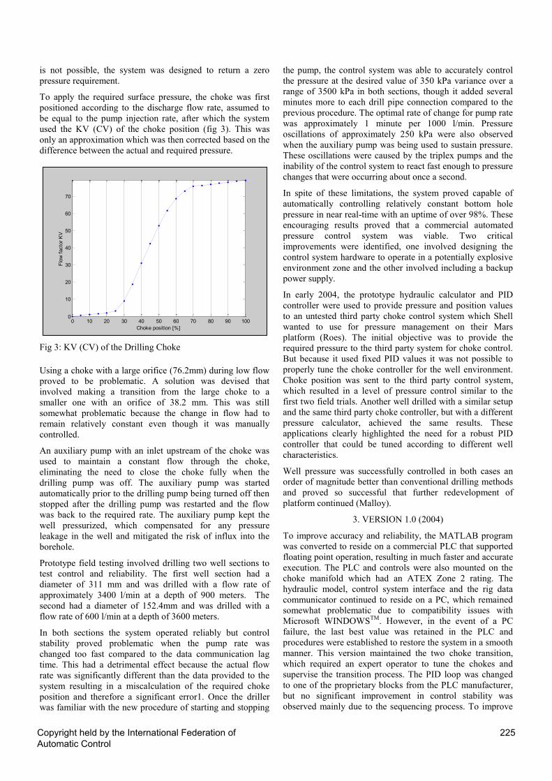
To apply the required surface pressure, the choke was first
positioned according to the discharge flow rate, assumed to
be equal to the pump injection rate, after which the system
used the KV (CV) of the choke position (fig 3). This was
only an approximation which was then corrected based on the
difference between the actual and required pressure.
Fig 3: KV (CV) of the Drilling Choke
Using a choke with a large orifice (76.2mm) during low flow
proved to be problematic. A solution was devised that
involved making a transition from the large choke to a
smaller one with an orifice of 38.2 mm. This was still
somewhat problematic because the change in flow had to
remain relatively constant even though it was manually
controlled.
An auxiliary pump with an inlet upstream of the choke was
used to maintain a constant flow through the choke,
eliminating the need to close the choke fully when the
drilling pump was off. The auxiliary pump was started
automatically prior to the drilling pump being turned off then
stopped after the drilling pump was restarted and the flow
was back to the required rate. The auxiliary pump kept the
well pressurized, which compensated for any pressure
leakage in the well and mitigated the risk of influx into the
borehole.
Prototype field testing involved drilling two well sections to
test control and reliability. The first well section had a
diameter of 311 mm and was drilled with a flow rate of
approximately 3400 l/min at a depth of 900 meters. The
second had a diameter of 152.4mm and was drilled with a
flow rate of 600 l/min at a depth of 3600 meters.
In both sections the system operated reliably but control
stability proved problematic when the pump rate was
changed too fast compared to the data communication lag
time. This had a detrimental effect because the actual flow
rate was significantly different than the data provided to the
system resulting in a miscalculation of the required choke
position and therefore a significant error1. Once the driller
was familiar with the new procedure of starting and stopping
the pump, the control system was able to accurately control
the pressure at the desired value of 350 kPa variance over a
range of 3500 kPa in both sections, though it added several
minutes more to each drill pipe connection compared to the
previous procedure. The optimal rate of change for pump rate
was approximately 1 minute per 1000 l/min. Pressure
oscillations of approximately 250 kPa were also observed
when the auxiliary pump was being used to sustain pressure.
These oscillations were caused by the triplex pumps and the
inability of the control system to react fast enough to pressure
changes that were occurring about once a second.
In spite of these limitations, the system proved capable of
automatically controlling relatively constant bottom hole
pressure in near real-time with an uptime of over 98%. These
encouraging results proved that a commercial automated
pressure control system was viable. Two critical
improvements were identified, one involved designing the
control system hardware to operate in a potentially explosive
environment zone and the other involved including a backup
power supply.
In early 2004, the prototype hydraulic calculator and PID
controller were used to provide pressure and position values
to an untested third party choke control system which Shell
wanted to use for pressure management on their Mars
platform (Roes). The initial objective was to provide the
required pressure to the third party system for choke control.
But because it used fixed PID values it was not possible to
properly tune the choke controller for the well environment.
Choke position was sent to the third party control system,
which resulted in a level of pressure control similar to the
first two field trials. Another well drilled with a similar setup
and the same third party choke controller, but with a different
pressure calculator, achieved the same results. These
applications clearly highlighted the need for a robust PID
controller that could be tuned according to different well
characteristics.
Well pressure was successfully controlled in both cases an
order of magnitude better than conventional drilling methods
and proved so successful that further redevelopment of
platform continued (Malloy).
3. VERSION 1.0 (2004)
To improve accuracy and reliability, the MATLAB program
was converted to reside on a commercial PLC that supported
floating point operation, resulting in much faster and accurate
execution. The PLC and controls were also mounted on the
choke manifold which had an ATEX Zone 2 rating. The
hydraulic model, control system interface and the rig data
communicator continued to reside on a PC, which remained
somewhat problematic due to compatibility issues with
Microsoft WINDOWSTM
. However, in the event of a PC
failure, the last best value was retained in the PLC and
procedures were established to restore the system in a smooth
manner. This version maintained the two choke transition,
which required an expert operator to tune the chokes and
supervise the transition process. The PID loop was changed
to one of the proprietary blocks from the PLC manufacturer,
but no significant improvement in control stability was
observed mainly due to the sequencing process. To improve
0 10 20 30 40 50 60 70 80 90 1000
10
20
30
40
50
60
70
Choke position [%]
Flo
w f
acto
r K
V
Copyright held by the International Federation ofAutomatic Control
225
calculations, high speed counters were added for direct
measurement of the drilling pump speed rather than relying
on WITS data. That significantly improved the speed and
reliability of the control system.
The earliest application of the first commercial version was
used by Shell on their Gannett platform in the U.K. North
Sea (Laird) to access stranded oil reserves. Shells‟s objective
was to avoid formation damage by reducing the amount of
weighting solids in the fluid and the differential pressure at
the reservoir. Surface control pressures were approximately
7000 kPa which significantly eclipsed previous maximum
control pressures of approximately 2000 kPa.
A Coiled-Tubing drilling unit was used which as its name
suggests, is a continuous length of pipe of several thousand
meters which is rolled onto a reel rather than using jointed
drill pipe. This type of drilling unit was used due to the
relatively small available space on the rig and its ability to
provide a relatively constant pump rate, which is inherently
unachievable with jointed drill pipe. There were however
several sudden and unexpected transient events due to the
drilling motor abruptly stalling, which flow out of the well
suddenly stop. These transients required rapid choke closure
and backpressure pump operation to maintain constant well
pressure and resulted in brief pressure spikes due the rapid
actuation of the choke followed by the pressure stabilizing
within an acceptable error of the required value. Had the
system been manually controlled it would not have been
possible to manage these abrupt changes and re-establish the
correct well pressure.
Uptime for the system was 98.8% or a total of 10.25 hrs
downtime and no significant pressure losses occurred due to
employing contingency measures. By employing the
automated pressure control system and utilizing a reduced
density, solids free drilling fluid, Shell realized nearly a
threefold increase in expected well productivity and an order
of magnitude lower water production.
An onshore location that had a higher pressure tolerance was
used for the next test of the system. For this application the
system was found to take too long due transport and rig up
which included a generator for the auxiliary pump. Tuning
the choke still took several hours which added to the rig time
for a marginal application which was previously done using
manual choke control by the senior rig supervisor. The
drillers were also not accustomed to starting and stopping the
pumps slow enough for the system to react since the manual
method had been to stop the pumps rapidly, close the choke
and then apply additional pressure as required. This resulted
in significantly higher and lower pressures being applied
compared to the manual method. The system did perform
well when the drillers were properly trained to slowly start
and stop the pumps but they typically required constant
supervision, again adding to the cost of the operation. The
system was partially used in manual mode to ensure the
correct pressure was applied by using the real time hydraulic
model. Although the well reached the planned depth, the
system was not considered economically viable unless
transportation costs could be lowered, rig up time reduced
and system performance improved.
4. VERSION 1.2 (2006)
The primary change to the system was the removal of the
transition sequence for the small bore. This eliminated
transition tuning which significantly improved pressure
stability and reduced control complexity. However, this
required a 75% increase in the backpressure pump flow rate,
which allowed the system to operate the choke at an optimal
position and in turn manage the pressure with small choke
movements, shown in fig 1 between 20 and 60 on the CV
curve. Without this feature the choke would have to operate
at a CV value below 20, where it would have little effect on
pressure. At that position the choke would have to move
rapidly, which could cause it to become unstable. Also,
different PID parameters would have been required to
maintain stability across the entire choke position range
which would have led to increased system complexity,
greater operator expertise, and a significantly longer time to
tune the system.
A number of land and offshore wells with specific safety and
redundancy requirements were drilled with constant well
pressure (Reitsma). The purpose was either to maintain a
stable borehole or prevent fluid losses. Of paramount
importance was to avoid an influx of reservoir fluids and to
detect it at the earliest possible movement if such an event
did occur (Montilva).
Although not strictly part of the automated pressure control
system, a Coriolis flow meter was incorporated into the
system to detect fluid kicks and losses. The meter is located
on the discharge line of the choke manifold and is used to
compare flow into the well with flow out of the well. A kick
is identified by an increase in flow out of the well compared
to flow in and a loss is identified by a decrease in flow out of
the well compared to flow int. The Coriolis flow meter is
highly sensitive to changes in flow and was instrumental in
aiding in detecting kicks and losses for two reasons, 1.
Managed Pressure Drilling Operations typically have a
reduced pressure margin between pore pressure and fracture
pressure, and 2. The driller is unable to observe potential
flow during static conditions except at the discharge into the
fluid holding tanks which may be some distance from his
station.
5. VERSION 2.0 (2008)
This version was entirely rewritten onto a new platform based
on the need for increased spare capacity and more precise
pressure control using a smaller auxiliary pump. Also,
version 1 had been built off of the prototype version which
still retained some of the native MATLAB code. Fixed values
that were embedded in the code were removed to allow for
easier customization at each new well location. The system
was also able to now control up to three chokes
simultaneously, have redundant pressure sensors, remotely
control several valves and monitor up to six drilling pumps.
The new platform was also designed to have a 50 – 100
millisecond refresh rate to ensure updates could be made at
least every 250 milliseconds.
Development included a new interface that was more
intuitive and included a monitor for the driller which
Copyright held by the International Federation ofAutomatic Control
226
provided pressure feedback as the pump speed was altered
rather than requiring supervision by an MPD specialist to not
change the pump rate faster than the choke could control the
well pressure. The feedback system displays a green
(normal), amber (reduce change of pump rate) or red light
(stop changing pump rate) so the driller can adjust pump
speed accordingly to maintain the green light. Some drillers
adapted well to this method and others still required
supervision, or due to space constraints it was not possible to
place the monitor where the driller could observe it.
A new PI controller was implemented for the mechanical
choke that did require CV measurements. Instead, course
positioning of the choke using an outer loop and a finer inner
control loop was developed. The inner loop is activated when
the actual well pressure approaches the required pressure and
switches back to coarse position if the actual well pressure is
significantly different than the required well pressure. This
method significantly improved the speed and stability of the
system since a large change in choke position could be made.
Operators were still required to tune the system by adjusting
the gain and integral values. For even the most experienced
operators this takes at least two hours and sometimes
substantially longer if conditions such as the bulk modulus of
the well changed. However, the advantage was that a smaller
pump could theoretically be used since the choke could
operate over a greater range.
The use of the system has been instrumental in providing
precise control of the well pressure primarily in offshore
operations. There are numerous references available but most
notable have been the contribution to full field offshore
redevelopment projects such as Shell Auger (Chustz) and
Talisman Malaysia (Fredericks).
6. VERSION 3.0 (2011)
The requirement for an operator to remain on the well
location in order to tune the choke controller, while greatly
improved from the original version still challenged consistent
service delivery because the skill set of the operator was
instrumental in determining how well the choke controlled
pressure. In fact, on the same project the day Operator might
apply different settings than the night Operator (Reitsma).
The training of operators also adds significantly to overhead
costs. As well it would not be possible to reduce personnel on
location and thus limited the deployment of the system based
on economics and / or accommodation space. Tuning of the
PI loop could also take several hours and would have to be
corrected as drilling conditions changed.
Methods such as neural networks, expert systems,
commercially available self-tuning systems, choke position
versus pressure tables, and fixing the integral time so that the
operator would only need to change the gain were
investigated as possible solutions but unfortunately all of
them provided a lesser degree of control and stability than
currently available, so did not offer the potential for reducing
training and personnel on location.
As a result, a project was undertaken to develop a proprietary
non-linear solution that would self adapt to the changing bulk
modulus which commonly occurs when drilling oil and gas
wells. Mechanical modifications were also made to the choke
actuator and hydraulic control system to increase the speed
and accuracy of the choke movement. As a result, the choke
actuator moves more than three times faster than the previous
choke actuator and with an order of magnitude greater
pressure control precision.
The new solution constructs the necessary algorithm based on
initial pressure and choke position feedback during an initial
calibration process that takes approximately two minutes.
After calibration, the system is capable of automatically
controlling the choke position based on the difference
between the required and actual well pressure. Minor
corrections to the algorithm are automatically made based on
pressure response during the normal drilling process.
Testing of the new controller was performed at the Louisiana
State University PERTT (Petroleum Engineering Research
Technology Transfer facility) well number 2 in Baton Rouge
Louisiana, which is used extensively for testing managed
pressure drilling systems and conducting full scale well
control training. While the system is designed for controlling
the well pressure during the sequence of starting and stopping
the drilling pumps, several other tests were also conducted to
test the overall stability. Testing was conducted over several
months but only the relevant results are presented.
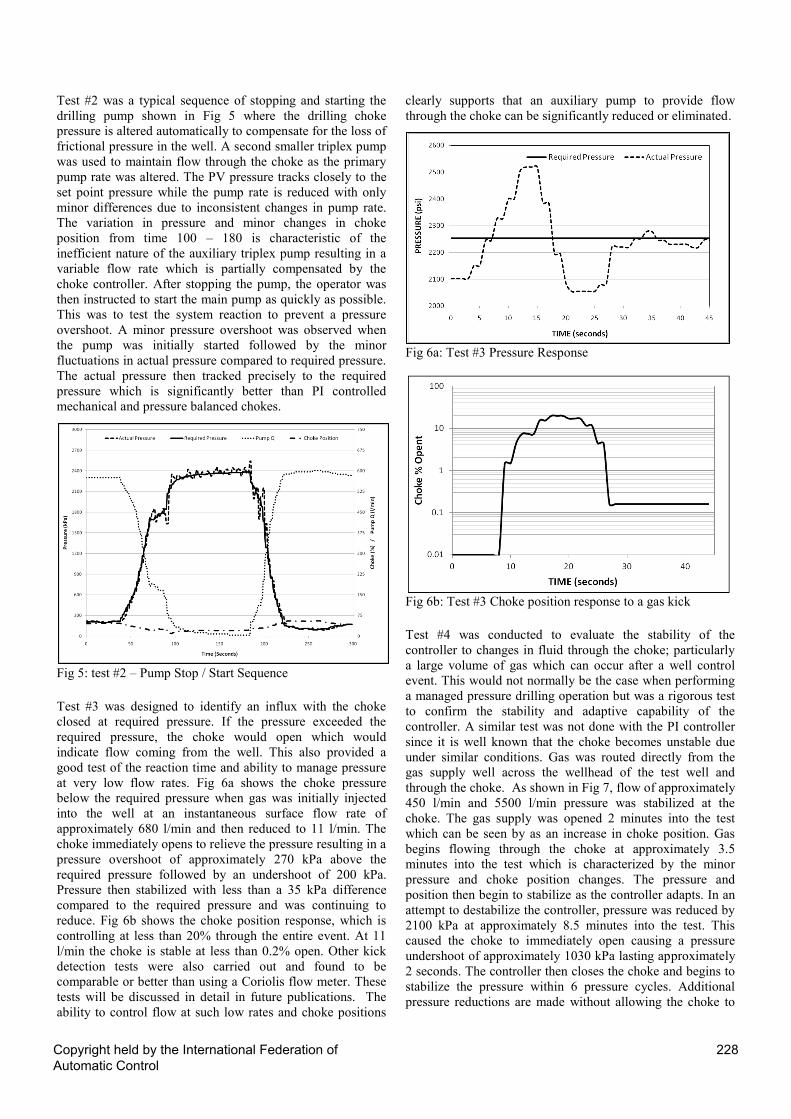
Test #1 involved manually increasing the well pressure in
350 kPa increments at a constant pump rate to test the ability
of the system to match the actual well pressure. Total system
reaction time which includes signal reception, processing and
the mechanical action of the choke hydraulics was
approximately one second. Fig 4 is a plot of test #1 showing
only a minor pressure overshoot before stabilizing at +/- 15
kPa of the required pressure. What is significant is that there
is no characteristic pressure oscillations normally associated
with a PI control as evident in the references mentioned.
Rather than step down the pressure in 350 kPa increments,
the pressure was decreased in a single 2100 kPa step to test
the stability of the system to correct for significant pressure
changes. The result was a relatively minor undershoot of
pressure and then pressure stabilized at +/- 15 kPa. This is a
significant improvement over PI controllers which can
usually provide +/- 250 kPa under ideal conditions.
Fig 4: Test #1 – Manual Set Point Pressure Changes
Copyright held by the International Federation ofAutomatic Control
227
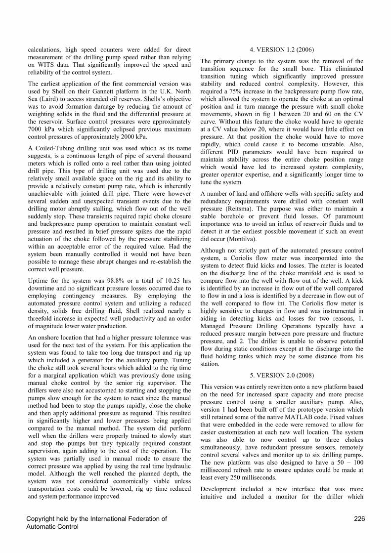
Test #2 was a typical sequence of stopping and starting the
drilling pump shown in Fig 5 where the drilling choke
pressure is altered automatically to compensate for the loss of
frictional pressure in the well. A second smaller triplex pump
was used to maintain flow through the choke as the primary
pump rate was altered. The PV pressure tracks closely to the
set point pressure while the pump rate is reduced with only
minor differences due to inconsistent changes in pump rate.
The variation in pressure and minor changes in choke
position from time 100 – 180 is characteristic of the
inefficient nature of the auxiliary triplex pump resulting in a
variable flow rate which is partially compensated by the
choke controller. After stopping the pump, the operator was
then instructed to start the main pump as quickly as possible.
This was to test the system reaction to prevent a pressure
overshoot. A minor pressure overshoot was observed when
the pump was initially started followed by the minor
fluctuations in actual pressure compared to required pressure.
The actual pressure then tracked precisely to the required
pressure which is significantly better than PI controlled
mechanical and pressure balanced chokes.
Fig 5: test #2 – Pump Stop / Start Sequence
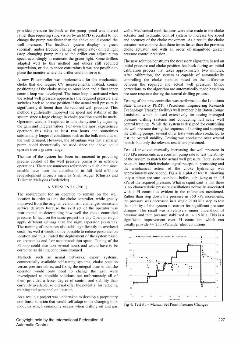
Test #3 was designed to identify an influx with the choke
closed at required pressure. If the pressure exceeded the
required pressure, the choke would open which would
indicate flow coming from the well. This also provided a
good test of the reaction time and ability to manage pressure
at very low flow rates. Fig 6a shows the choke pressure
below the required pressure when gas was initially injected
into the well at an instantaneous surface flow rate of
approximately 680 l/min and then reduced to 11 l/min. The
choke immediately opens to relieve the pressure resulting in a
pressure overshoot of approximately 270 kPa above the
required pressure followed by an undershoot of 200 kPa.
Pressure then stabilized with less than a 35 kPa difference
compared to the required pressure and was continuing to
reduce. Fig 6b shows the choke position response, which is
controlling at less than 20% through the entire event. At 11
l/min the choke is stable at less than 0.2% open. Other kick
detection tests were also carried out and found to be
comparable or better than using a Coriolis flow meter. These
tests will be discussed in detail in future publications. The
ability to control flow at such low rates and choke positions
clearly supports that an auxiliary pump to provide flow
through the choke can be significantly reduced or eliminated.
Fig 6a: Test #3 Pressure Response
Fig 6b: Test #3 Choke position response to a gas kick
Test #4 was conducted to evaluate the stability of the
controller to changes in fluid through the choke; particularly
a large volume of gas which can occur after a well control
event. This would not normally be the case when performing
a managed pressure drilling operation but was a rigorous test
to confirm the stability and adaptive capability of the
controller. A similar test was not done with the PI controller
since it is well known that the choke becomes unstable due
under similar conditions. Gas was routed directly from the
gas supply well across the wellhead of the test well and
through the choke. As shown in Fig 7, flow of approximately
450 l/min and 5500 l/min pressure was stabilized at the
choke. The gas supply was opened 2 minutes into the test
which can be seen by as an increase in choke position. Gas
begins flowing through the choke at approximately 3.5
minutes into the test which is characterized by the minor
pressure and choke position changes. The pressure and
position then begin to stabilize as the controller adapts. In an
attempt to destabilize the controller, pressure was reduced by
2100 kPa at approximately 8.5 minutes into the test. This
caused the choke to immediately open causing a pressure
undershoot of approximately 1030 kPa lasting approximately
2 seconds. The controller then closes the choke and begins to
stabilize the pressure within 6 pressure cycles. Additional
pressure reductions are made without allowing the choke to
Copyright held by the International Federation ofAutomatic Control
228

fully compensate for the previous change in pressure with
continually improving pressure stabilization.
Fig 7: New Controller Test 4 – Gas Flow Stability Test
Test #5 was to determine system stability with the driller
making erratic changes to the drilling pump rate in an attempt
to destabilize the choke controller below the 20% operating
range of the choke which is historically considered to be an
unstable region for choke performance (Reitsma). As shown
in fig 8a and fig 8b the pressure set point was automatically
varied according to the change in pump rate as would be the
case in a typical field application as the friction pressure in
the well also changed. Several times the choke almost closes
fully and in another case it closes fully due to the rapid
change in pump rate and resulting error between SP and PV.
The choke then reopens due to pump rate changes and
remains stable throughout the test as other pump rate changes
are made. There were several other tests conducted in order
to attempt to destabilize the choke but the choke remained
stable.
Fig 8a and 8b: Attempt to Destabilize Choke Controller
7. FUTURE PRESSURE CONTROL DEVELOPMENT
The choke controller in its present state has been developed
as purely reactionary to the change in rig and well conditions
without the benefit of using a feed forward controller. Future
development will be to coordinate pump speed, hoisting,
rotary control and vessel movement in floating rig
applications with the choke controller. Changes in well
conditions such as gas content, geometry and fluid properties
also need to be included in the control system process.
8. CONCLUSIONS
The choke control system to control well pressure has
been under continuous development for more than 10
years, progressing from prototype to the current system
with discreet development objectives.
Removing the variables from the source code enabled the
operators to configure the system on location without
assistance from the support group.
The PI choke controller was improved with the removal
of the choke transition but still requires a trained
operator to perform the tuning and a larger pump.
Improvements in the performance of the system were
significant in reducing the pump size, reducing training
and improving stability, however removal of the PI
control loop was seen as a requirement in order to further
reduce training and improve service quality.
The newly developed non-linear controller has proven to
be stable, fast and reliable in testing compared to using
the current PI control system, requires practically no
training and provides a higher level of service quality.
Throughout the development of the system it has been
successfully used to drill offshore and onshore resulting
in significant cost savings and additional reserves. In
some cases it would not have been technically
impossible to drill the wells resulting in the stranding of
the reserves.
ACKNOWLEDGEMENT
The authors wish to thank the many engineering and
operations personnel who have dedicated themselves to the
development of the control system from initial concept to the
current system. Their desire for continuous improvement and
to remain the best in class has made a significant difference
to the quality and capability of the system. Thanks to Shell
for their initial vision that automation is required to assure
reliable pressure control. Thanks to Kenda Capital and the
former board of At Balance for providing their guidance.
Finally, thanks to Schlumberger management, for permission
to publish this paper.
Copyright held by the International Federation ofAutomatic Control
229
REFERENCES
E.J. van Riet, D. Reitsma, B Vandecraen, SPE 85310, “Development
and testing of a fully automated system to accurately control downhole pressure during drilling operations”, SPE/IADC Middle East Drilling
Technology Conference & Exhibition, 2004.
V. Roes, D. Reitsma, Shell; L. Smith, J. McCaskill, F. Hefren, SPE
98077, “First deepwater application of dynamic annular Pressure
control succeeds”, SPE/IADC Drilling Conference & Exhibition, 2006
Kenneth P. Malloy, Vincent Rose, OTC 18461, “Improved reliability of drilling operations using managed pressure drilling
technology: a case study in a brown field environment”, Offshore
Technology Conference, 2007
A. Laird, K. McFadzean, J. Edgar, I. Harty, SPE 96404 “Offshore
implementation of through-tubing dynamic annulus pressure controlled (DAPC) coiled-tubing drilling”, Offshore Europe , 2005.
Don Reitsma, Paul Fredericks, Roger Suter, “Successful application of new pressure-control technology developed for land-based managed
pressure drilling operation”, IADC/SPE Managed Pressure Drilling
Conference and Exhibition, 2007.
Julio Montilva, Paul Fredericks, Ossama Sehsah, SPE 128923, “New automated control system manages pressure and return flow while
drilling and cementing casing in depleted onshore field”,
IADC/SPE Drilling Conference and Exhibition, 2010
Mark J. Chustz, James May, Cameron Wallace, Don Reitsma, Paul
Fredericks, Scott Dickinson, Larry D. Smith, SPE 108348 “Managed pressure drilling with dynamic annular pressure control
system proves successful in redevelopment program on Auger TLP in
deepwater Gulf of Mexico”, IADC/SPE Managed Pressure Drilling Conference and Exhibition, 2007.
Mark J. Chustz, Larry D. Smith, Dwayne Dell, SPE 112662, “Managed pressure drilling success continues on Auger TLP”, IADC/SPE
Drilling Conference, 2008
Paul Fredericks, Greg Garcia, Ossama Sehsah, SPE 130319, “Managed
pressure drilling avoids losses while improving drilling and ECD
management in the Gulf of Thailand”, SPE/IADC Managed Pressure Drilling and Underbalanced Operations Conference and Exhibition,
2010.
Don Reitsma, Yawan Couturier, Jesse Hardt, “Fully automated MPD choke
controller testing and field trials”, SPE/IADC Managed Pressure
Drilling and Underbalanced Operations Conference and Exhibition,
2011 (unpublished)
Copyright held by the International Federation ofAutomatic Control
230
Related Documents


