1 A SEMINAR REPORT ON CDMA TECHNOLOGY SUBMITTED BY: ANKUR BANSAL Roll No. 0722631011 DEPARTMENT OF ELECTRONICS AND COMMUNICATION ENGINEERING BACHLOR OF TECHNOLOGY (ECE, VII SEM) SESSION ± 2010-2011 D.J COLLEGE OF ENGINEERING & TECHNOLOGY MODINAGAR-201204(U.P.) U.P. TECHNICAL UNIVERSITY, LUCKNOW 2010-2011

Welcome message from author
This document is posted to help you gain knowledge. Please leave a comment to let me know what you think about it! Share it to your friends and learn new things together.
Transcript

8/8/2019 New Cdma Report
http://slidepdf.com/reader/full/new-cdma-report 1/25
1
A
SEMINAR REPORT
ON
CDMA TECHNOLOGY
SUBMITTED BY:
ANKUR BANSAL
Roll No. 0722631011
DEPARTMENT OF ELECTRONICS AND
COMMUNICATION ENGINEERING
BACHLOR OF TECHNOLOGY
(ECE, VII SEM)
SESSION ± 2010-2011
D.J COLLEGE OF ENGINEERING & TECHNOLOGY
MODINAGAR-201204(U.P.)
U.P. TECHNICAL UNIVERSITY, LUCKNOW
2010-2011
8/8/2019 New Cdma Report
http://slidepdf.com/reader/full/new-cdma-report 2/25

8/8/2019 New Cdma Report
http://slidepdf.com/reader/full/new-cdma-report 3/25
3
ACKNOWLEDGEMENT
³Appreciation can make a day, even change a life. Your willingness to put it into words is all that is necessary´.
I thank God Almighty for the successful completion of my seminar.
I express my sincere gratitude to Mr. Sumit Gupta, Head of the Department,Electronics & Communication Engineering. I am deeply indebted to Mr.
Prabhat Mishra, for their valuable advice and guidance. I am also grateful to
all other members of the faculty of Electronics & Communication department
for their co-operation.
I am grateful to DJCET, Modinagar for giving me the opportunity to undergo
this Seminar Program..
Last but not the least; I would like to thank my friends for their valuable inputs
without which this seminar would not have been complete.
ANKUR BANSAL

8/8/2019 New Cdma Report
http://slidepdf.com/reader/full/new-cdma-report 4/25
4
CONTENT
What is CDMA
Multiple Access Comparison
y FDMA
y TDMA
y CDMA CDMA Technology
y Spread Spectrum
y Introduction to Spread Spectrum Communication
y Three types of Spread Spectrum
y Direct Sequence Spread Spectrum Coding
y Generating Pseudo-Random Code
y Code Correlation
y Pseudo-Noise Spreading
y System Capicity
The Spreading Process
CDMA Benefits
CDMA Implementation
y CDMA Channel
y CDMA forward Channel
Pilot Channel
Sync Channel
Paging Channel
Forward Traffic Channel
y CDMA Reverse Channel
Access Channel
Reverse Traffic Channel CDMA Modulation
Transmitting Data
Receiving Data
y Demodulation
y Code acquisition lock
y Correlation & data dispreading
y Automatic power control
Receiving an incoming call in CDMA
Conclusion
Refrence

8/8/2019 New Cdma Report
http://slidepdf.com/reader/full/new-cdma-report 5/25
5
WHAT IS CDMA?
(Code Division Multiple Access) A method for
transmitting realtime signals over a shared portion of the
spectrum. The foremost application of CDMA is the digital
cellular phone technology that operates in the 800MHz band and
1.9GHz . Unlike GSM and TDMA, which divides the spectrum
into different time slots CDMA uses a spread spectrum technique
to assi gn a code to each conversati on. After the speech codecconverts voice to digital, CDMA spreads the voice stream over
the full 1.25MHz bandwidth of the CDMA channel coding each
stream separately so it can be decoded at the receiving end. Therate of the spreading signal is known as the ³chip rate,´ as each
bit in the spreading signal is called a ³chip´ voice conversationsuse the full bandwidth at the same time. One bit from each
conversation is multiplied into 128 coded bits by the spreadingtechniques, giving the receiving side an enormous amount of data
it can average just to determine the value of one bit.
CDMA phones are noted for their excellent call quality
and low current draw CDMA is less costly to implement,requiring fewer cell sites than the GSM and TDMA digital cell
phone systems and providing three to five times the calling
capacity. It provides more than 10 times the capacity of the
analog cell phone system (AMPS). CDMA is also expected to
become the third-generation (3G) technology for GSM.
CDMA transmission has been used by the military for
secure phone calls. Unlike FDMA and TDMA methods, CDMA¶s
wide spreading signal makes it difficult to detect and jam.
One of the most important concepts to any cellular telephone system is that of ³multiple access´, meaning that
multiple, simultaneous users can be supported. In other words, alarge number of users share a common pool of radio channels and
any user can gain access to any channel (each user is not alwaysassigned to the same c hannel). A channel can be thought of as
merely a portion of the limited radio resource which is temporaryallocated for a specific purpose, such as someone¶s phone call. A
multiple access method is a definition of how the radio spectrum
is divided into channels and how channels are allocated to the
many users of the system.

8/8/2019 New Cdma Report
http://slidepdf.com/reader/full/new-cdma-report 6/25
6
MULTIPLE ACCESS COMPARISON
It is easier to understand CDMA if it is compared with other multiple
access technologies. The following sections describe the fundamental
differences between a Frequency Division Multiple Access Analog technology
(FDMA), a Time Division Multiple Access Digital technology (TDMA) and a
Code Division Multiple Access Digital technology (CDMA).
FDMA - Frequency Division Multiple Access
FDMA is used for standard analog cellular. Each user is
assigned a discrete slice of the RF spectrum. FDMA permits onlyone user per channel since it allows the user to use the channel
100% of the time. Therefore, only the frequency ³dimension´ isused to define channels.
TDMA - Time Division Multiple Access
The key point to make about TDMA is that users are still
assigned a discrete slice of RF spectrum, but multiple users now
share that RF carrier on a time slot basis. Each of the users
alternate their use of the RF channel. Frequency division is still
employed, but these carriers are now further sub -divided into
some number of time slots per carrier.
A user is assigned a particular time slot in a carrier and
can only send or receive information at those times. This is true
whether or not the other time slots are being used. Information
flow is not continuous for any user, but rather is sent and
received in ³bursts.´ The bursts are re-assembled at the receiving
end, and appear to provide continuous sound because the p rocessis very fast.

8/8/2019 New Cdma Report
http://slidepdf.com/reader/full/new-cdma-report 7/25
7
CDMA - Code Division Multiple Access
IS-95 uses a multiple access spectrum spreading technique
called Direct Sequence
(DS) CDMA.
Each user is assigned a binary, Direct Sequence code
during a call. The DS code is a signal generated by linear
modulation with wideband Pseudorandorn Noise (PN) sequences.As a result, DS CDMA uses much wider signals than those used
in other technologies. Wideband signals reduce interference andallow onecell frequency reuse.
There is no time division, and all users use the entirecarrier, all of the time.
Figure 3: DS-CDMA
8/8/2019 New Cdma Report
http://slidepdf.com/reader/full/new-cdma-report 8/25
8
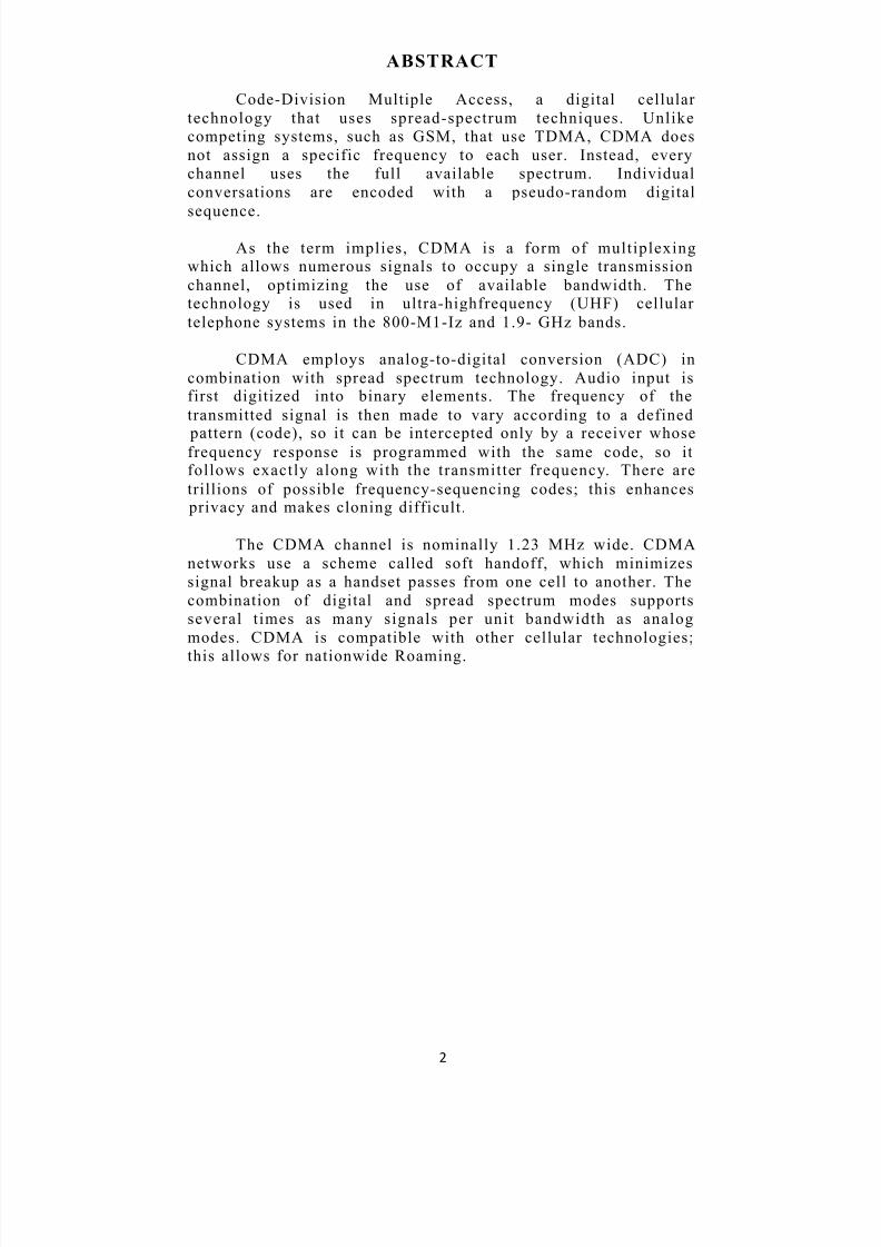
CDMA TECHNOLOGY
Though CDMA application in cellular telephony is relatively new, it is not a
new technology. CDMA has been used in many military applications, such as
anti- jamming (because of the spread signal, it is difficult to jam or interfere
with a CDMA signal), ranging (measuring the distance of the transmission to
know when it will be received), and secure communications (the spread
spectrum signal is very hard to detect).
Spread Spectrum
CDMA is a ³spread spectrum´ technology, which means
that it spreads the information contained in a particular signal of interest over a much greater bandwidth than the original signal.
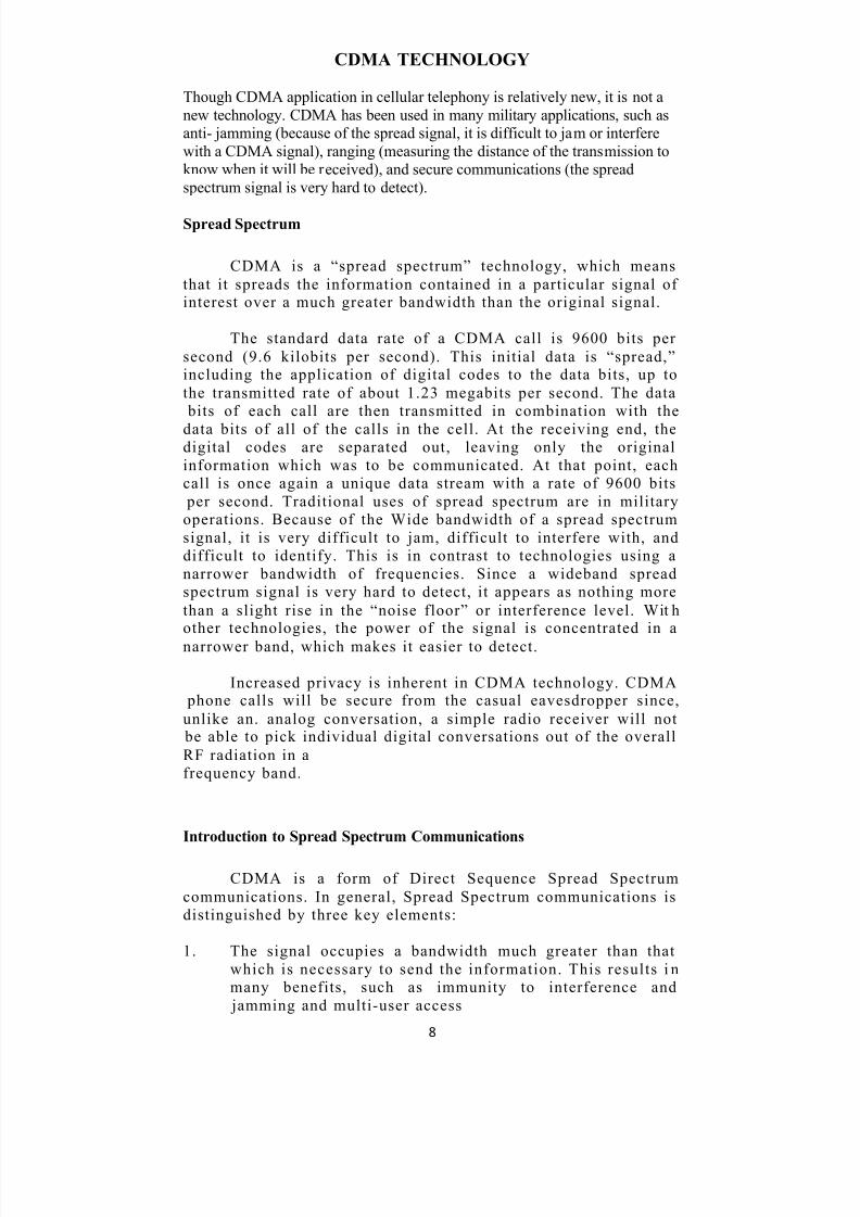
The standard data rate of a CDMA call is 9600 bits per
second (9.6 kilobits per second). This initial data is ³spread,´including the application of digital codes to the data bits, up to
the transmitted rate of about 1.23 megabits per second. The data
bits of each call are then transmitted in combination with the
data bits of all of the calls in the cell. At the receiving end, thedigital codes are separated out, leaving only the original
information which was to be communicated. At that point, each
call is once again a unique data stream with a rate of 9600 bits
per second. Traditional uses of spread spectrum are in military
operations. Because of the Wide bandwidth of a spread spectrum
signal, it is very difficult to jam, difficult to interfere with, and
difficult to identify. This is in contrast to technologies using a
narrower bandwidth of frequencies. Since a wideband spread
spectrum signal is very hard to detect, it appears as nothing more
than a slight rise in the ³noise floor´ or interference level. Wit hother technologies, the power of the signal is concentrated in a
narrower band, which makes it easier to detect.
Increased privacy is inherent in CDMA technology. CDMA phone calls will be secure from the casual eavesdropper since,
unlike an. analog conversation, a simple radio receiver will not be able to pick individual digital conversations out of the overall
RF radiation in a
frequency band.
Introduction to Spread Spectrum Communications
CDMA is a form of Direct Sequence Spread Spectrum
communications. In general, Spread Spectrum communications is
distinguished by three key elements:
1. The signal occupies a bandwidth much greater than that
which is necessary to send the information. This results i n
many benefits, such as immunity to interference and
jamming and multi-user access

8/8/2019 New Cdma Report
http://slidepdf.com/reader/full/new-cdma-report 9/25
9
2. The bandwidth is spread by means of a code which isindependent of the data. The independence of the code
distinguishes this from standard modulation schemes inwhich the data modulation will always spread the spectrum
somewhat.
3. The receiver synchronizes to the code to recover the data.
The use of an independent code and synchronous
reception allows multiple users to access the same
frequency band at the same time.
In order to protect the signal, the code used is
pseudo-random. It appears random, but is actually
deterministic, so that the receivefcan reconstruct the code
for synchronous detection. This pseudo-random code is
also called pseudo-noise (PN).
Three Types of Spread Spectrum Communications
There are three ways to spread the bandwidth of the signal:y Frequency hopping. The signal is rapidly switched
between different frequencies within the hopping
bandwidth pseudorandomly, and the receiver knows
before hand where to find the signal at any given time.
y Time hopping. The signal is transmitted in short bursts
pseudo-randomly, and the receiver knows beforehand
when to expect the burst.
y Direct sequence. The digital data is directly coded at amuch higher frequency. The code is generat ed pseudo -
randomly, the receiver knows how to generate the samecode, and correlates the received signal with that code to
extract the data.
Direct Sequence Spread Spectrum
CDMA is a Direct Sequence Spread Spectrum system. The
CDMA system works directly on 64 kbit/sec digital signals.
These signals can be digitized voice, ISDN channels, modem
data, etc.
Signal transmission consists of the following steps:
1.
A pseudo-random code is generated, different for eachchannel and each successive connection.
2. The Information data modulates the pseudo-random code
(the Information data is ³spread´).
3. The result ing signal modulates a carrier.
4. The modulated carrier is amplifi ed and broadcast.

8/8/2019 New Cdma Report
http://slidepdf.com/reader/full/new-cdma-report 10/25
10
Signal reception consists of the following steps:
1. The carrier is received and amplifi ed.2. The received signal is mixed with a local carrier to
recover the spread digital signal.
3. A pseudo-ra ndom code is generated, matching the
anticipated signal.
4. The receiver acquires the received code and phase
locks its own code to it.
5. The received signal is correlated with the generated
code, extracting the Information data.
The main Problem with Direct Sequence is the Near -Far
effect. If there are more then one users active, the transmitt ed
power of nonreference users is suppressed by a factor dependent
on the (partial) cross correlation between the code of thereference user and the code of a non -ref erence user. However
when a non- reference user is closer to the receiver then th ereference-user, it is possible that the interference caused by this
non-reference user (however suppressed) has more power thereference user. Now only the non-reference user will be received,
this nasty property is called the near -far effect.
One way to beat the near -far effect can be exploit ed in
cellular systems. In such systems the base station takes care that
all users.have such a power that the received power at the base
station is equal for all users.
In non-cellular systems the influence of the near-far effect
can be reduced by using the frequency-hopping spread spectrum
technique.
CDMA uses a form of direct sequence. Direct sequence is,
in essence, multipli cation of a more conventional ommunication
waveform by a pseudonoise (PN) ±1 binary sequence in the
transmitter.
8/8/2019 New Cdma Report
http://slidepdf.com/reader/full/new-cdma-report 11/25
11
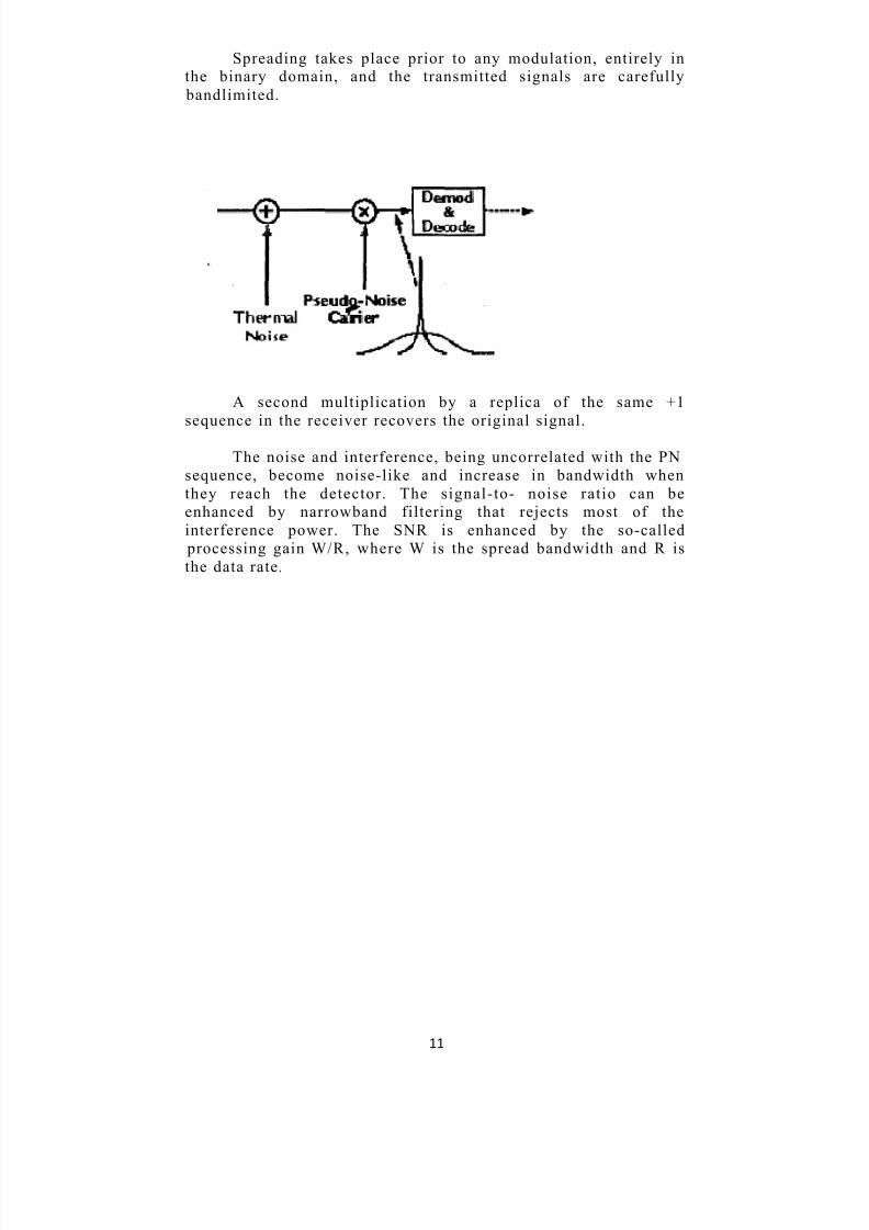
Spreading takes place prior to any modulation, entirely inthe binary domain, and the transmitted signals are carefully
bandlimited.
A second multiplication by a replica of the same +1
sequence in the receiver recovers the original signal.
The noise and interference, being uncorrelated with the PN
sequence, become noise-like and increase in bandwidth when
they reach the detector. The signal-to- noise ratio can be
enhanced by narrowband filtering that rejects most of the
interference power. The SNR is enhanced by the so-called
processing gain W/R, where W is the spread bandwidth and R is
the data rate.

8/8/2019 New Cdma Report
http://slidepdf.com/reader/full/new-cdma-report 12/25
12
CODING
CDMA uses unique spreading codes to spread the basebanddata before transmission. The signal is transmitted in a channel,
which is below noise level. The receiver then uses a correlator to
despread the wanted signal, which is passed through a narrow
bandpass filter. Unwanted signals will not be despread and will
not pass through the filter. Codes take the form of a carefully
designed one/zero sequence produced at a much higher rate thanthat of the baseband data. The rate of a spreading code isreferred to as chip rate rather than bit rate.
Generating Pseudo-Random Codes
For each channel the base station generates a unique code
that changes for every connection. The base station adds together
all the coded transmissions for every subscriber. The subscriber
unit correctly generates its own matching code and uses it toextract the appropriate signals. Note that each subscriber uses
several independent channels.
8/8/2019 New Cdma Report
http://slidepdf.com/reader/full/new-cdma-report 13/25
13
In order for all this to occur, the pseudo-random code musthave the following properties:
1. It must be deterministic. The subscriber station must be
able to independently generate the code that matches the
base stat ion code.
2. It must appear ra ndom to a l istener without prior
knowledge of the code (i.e. it has the statistical properties
of sampled white noise).
3. The cross-corr elation bet ween any two codes must b e
small (see below for more information on code
correlation).
4. The code must have a long period (i.e. a long time before
the code repeats itself).
Code Correlation
In this context, correlation has a specific mathematical
meaning. In general the correlation function has these properties:
y It equals 1 if the two codes are identical
y It equals 0 of the two codes have nothing in commony Intermediate values indicate how much the codes have in
common. The more they have in common, the harder it is
for the receiver to extract the appropriate signal. There are
two correlation functions:
y Cross-Correlation: The correlation of two different codes.As we¶ve said, this should be as small as possible.
y Auto-Correlation: The correlation of a code with a time -delayed version of itself. In order to reject multi-path
interference, this function should equal 0 for any time
delay other than zero.
The receiver uses cross-correlation to separate theappropriate signal from signals meant for other receivers, and
auto-correlation to reject multi-path interference.
Pseudo-Noise Spreading
The FEC coded Information data modulates the
pseudorandom code,, : - -
Some terminology related to the pseudo-random code:
y Chipping Frequency (fe): the bit rate of the PN code.
y Information rate (f): the bit rate of the digital data. -
y Chip: One bit of the PN code.
y Epoch: The length of time before the code starts repeating
itself (the period of the code). The epoch must be longer
than the round trip propagation delay (The epoch is on the
order of several seconds).
The bandwidth of a digital signal is twice its bit rate. The

8/8/2019 New Cdma Report
http://slidepdf.com/reader/full/new-cdma-report 14/25
14
bandwidth of the combination of the two, information data (f)and the PN code, for fc>fi, can be approximated by the
bandwidt h of the PN code.
System Capacity
The capacity of a system is approximated by
WhereCmax Is the maximum number of simultaneous calls
G p Is the processing gain
E b / No Is the total signal to noise ratio per bit, and
Is the cell interference factor
The capacity is directly proportional to the processing gain. Capacity is also
inversely proportional to the signal to noise ratio of the received signal. So, the
smaller the transmitted signal, the larger the system capacity. Both the RCS
and FSU control the power transmitted by the other so that the received signal
is as small as possible while maintaining a minimum signal to noise ratio. This
maximizes system capacity.
8/8/2019 New Cdma Report
http://slidepdf.com/reader/full/new-cdma-report 15/25
15
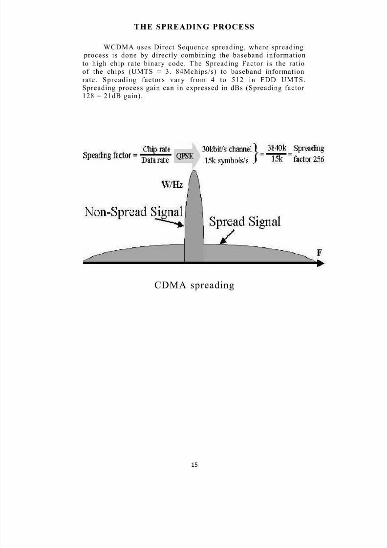
THE SPREADING PROCESS
WCDMA uses Direct Sequence spreading, where spreading process is done by directly combining the baseband information
to high chip rate binary code. The Spreading Factor is the ratio
of the chips (UMTS = 3. 84Mchips/s) to baseband information
rate. Spreading factors vary from 4 to 512 in FDD UMTS.
Spreading process gain can in expressed in dBs (Spreading factor
128 = 21dB gain).
CDMA spreading

8/8/2019 New Cdma Report
http://slidepdf.com/reader/full/new-cdma-report 16/25
16
CDMA BENEFITS
BENEFIT 1: CDMA CAPACITY INCREASES
CDMA anti Cell Reuse
Eb/No and Interference Threshold
Examples of Capacity Improvements
Other influence on Capacity
BENEFIT 2: IMPROVED CALL QUALITY
Advanced Error Detection and! Error Correction Sophisticated Vocoders
Multiple Levels of DiversitySoft Handoff
Precise Power Control
BENEFIT 3: SIMPLIFIED SYSTEM PLANNING
BENEFIT 4: ENHANCED PRIVACY
BENEFIT 5: IMPROVED COVERAGEBENEFIT 6: INCREASED PORTABLE TALKTIMEBENEFIT 7:BANDWIDTH ON DEMAND

8/8/2019 New Cdma Report
http://slidepdf.com/reader/full/new-cdma-report 17/25
17
CDMA IMPLEMENTATION
CDMA Channels
CDMA traffic channels are different: they are dependenton the equipment platform. Channels are designated in three
ways-effective traffic channels, actual traffic channels and physical traffic channels.
y The number of ³Effective´ traffic channels includes thetraffic carrying channels less the soft handoff channels.
The capacity of an effective traffic channel is equivalent
to the traffic carrying capacity of an analog traffic
channel.
y The number of ³Actual´ traffic channels includes the
effective traffic channels, plus channels allocated for soft
handoff.
y The number of ³Physical´ traffic channels includes thePilot channels, the Sync channels, the Paging channels, the
Soft Handoff Overhead channels and the Effective (voiceand data) traffic channels.
CDMA Forward Channels
Pilot Channel
The pilot channel is used by the mobile unit to obtaininitial system synchronization and to provide time, frequency,
and phase tracking of signals from the cell site.
Sync ChannelThis channel provides cell site identification, pilot
transmit
power, and the cell site pilot pseudo-random (PN) phase offset
information. With this information the mobile units can establish
the System Time as well as the proper transmit power level to
use to initiate a call.
Paging ChannelThe mobile unit will begin monitoring the paging channel
after it has set its timing to the System Time provided by the
sync channel. Once a mobile unit has been paged and
acknowledges that page, call setup and traffic channel
assignment information is then passed on this channel to the
mobile unit.
Forward Traffic ChannelThis channel carries the actual phone call and carries the
voice and mobile power control information from the basestation to the mobile unit.

8/8/2019 New Cdma Report
http://slidepdf.com/reader/full/new-cdma-report 18/25
18
CDMA Reverse Channels
Access Channel
When the mobile unit is not active on a traffic channel, it
will communicate to the base station over the access channel.
This communication includes registration requests, responses to
pages, and call originat ions. The access channels are paired w it h
a corresponding paging channel.
Reverse Traffic ChannelThis channel carries the other half of the actual phone call
and carries the voice and mobile power control information fromthe mobile unit to the base station.

8/8/2019 New Cdma Report
http://slidepdf.com/reader/full/new-cdma-report 19/25
19
CDMA Modulation
Both the Forward and Reverse Traffic Channels use asimilar control structure consisting of 20 millisecond frames. For
the system, frames can be sent at either 14400, 9600, 7200, 4800,
3600, 2400, 1800, or 1200 bps. For example, with a Traffic
Channel operating at 9600 bps, the rate can vary from frame to
frame, and can be 9600, 4800, 2400, or 1200 bps. The receiver
detects the rate of the frame and processes it at the correct rate.This technique allows the channel rate to dynamically adapt tothe speech or data activit y. For speech, when a talker pauses, the
transmission rate is reduced to a low rate. When the talker speaks, the system instantaneously shifts to using a higher
transmission rate. This technique decreases the interference to
other CDMA signals and thus allows an increase in system
capacity. CDMA starts with a basic data rate of 9600 bits per
second. T his is then spread to a transmitted bit rate, or chip rat e
(the transmitted bits are called chips), of 1.2288 MHz. The
spreading process applies digital codes to the data bits, which
increases the data rate while adding redundancy to the system.
The chips are transmitted using a form of QPSK
(quadrature phase shift keying) modulation which has been
filtered to limit the bandwidth of the signal. This is added to the
signal of all the other users in that cell. When the signal is
received, the coding is removed from the desired signal,returning it to a rate of 9600 bps. When the decoding is applied
to the other users¶ codes, there is no despreading; the signalsmaintain the 1.2288 MHz bandwidth. The ratio of transmitted
bits or chips to data bits is the coding gain. The coding gain for the IS-95 CDMA system is 128, or 21 dB.
Input data
CDMA works on Information data from several possible
sources, such as digitized voice or ISDN channels. Dat rates canvary, here are some examples:

8/8/2019 New Cdma Report
http://slidepdf.com/reader/full/new-cdma-report 20/25
20
The system works with 64 kBits/sec data, but can acceptinput rates of 8, 16, 32, or 64 kBits/sec. Inputs of less than 64
kBits/sec are padded with extra bits to bring them up to 64kBits/sec. For inputs of 8, 16, 32, or 64 kBits/sec, the system
applies Forward Error Correction (FEC) coding, which doubles
the bit rate, up to 128 kbits/sec. The Complex Modulation
scheme (which we¶ll discuss in more detail later), transmits two
bits at a time, in two bit symbols. For inputs of less than 64
kbits/sec, each symbol is repeated to bring the transmission rate
up to 64 kilosymbols/sec. Each component of the complex signal
carries one bit of the two bit symbol, at 64 kBits/sec, as shown
below

8/8/2019 New Cdma Report
http://slidepdf.com/reader/full/new-cdma-report 21/25
21
Transmitting Data
The resultant coded signal next modulates an RF carrier
for transmission using Quadrature Phase Shift Keying (QPSK).
QPSK uses four different states to encode each symbol. The four
states are phase shifts of the carrier spaced 90_ apart. By
convention, the phase shifts are 45, 135, 225, and 315 degrees.
Since there are four possible states used to encode binary
information, each state represents two bits. This two bit ³word´
is called a symbol.
Receiving Data
The receiver performs the following steps to extract the
Information:
Demodulation
Code acquisition and lock
Correlation of code with signal
Decoding of Information data
Demodulation
The receiver generates two reference waves, a Cosine wave
and a Sine wave. Separately mixing each with the received
carrier, the receiver extracts 1(t) and Q(t). Analog to Digital
converters restore the 8-bit words representing the I and Q chips.
Code Acquisition and Lock
The receiver, as described earlier, generates its owncomplex PN code that matches the code generated by the
transmitter. However, the local code must be phase- locked tothe encoded data.
Correlation and Data Despreading
Once the PN code is phase-locked to the pilot, the received
signal is sent to a correlator that multiplies it with the complex
PN code, extracting the I and Q data meant for that receiver. The
receiver reconstructs the Information data from the I and Q data.
Automatic Power Control
The RCS gets bombarded by signals from many FSUs.
Some of these FSUs are close and their signals are much stronger
than FSUs farther away. This results in the Near/Far problem
inherent in CDMA communications. System .Capacity is also
dependant on signal power. For these reasons, both the RCS andFSU measure the received power and send signals to control the
other¶s transmit power

8/8/2019 New Cdma Report
http://slidepdf.com/reader/full/new-cdma-report 22/25
22
Receiving an Incoming Call in CDMA
y All idle mobiles monitor the paging channel to receiveincoming calls.
y When an incoming call appears, the paging channelnotifies the mobile in a General Page Message.
y A mobile which has been paged sends a Page Response
Message on the access channel.
y The system sets up a traffic channel for the call, thennotifies the mobile to use it with a Channel Assignment
Message.
y The mobile and the base station notice each other¶s trafficchannel signals and confirm their presence by exchanging
acknowledgment messages.
y The base station and the mobile negotiate what type of call
this will be -- I.e., 13k voice, etc.
y The mobile is told to ring and given a ³calling line ID´ to
display.
y When the human user presses the send button, the audio
path is complet ed and the call proceeds.
8/8/2019 New Cdma Report
http://slidepdf.com/reader/full/new-cdma-report 23/25
23
cdmaOne: The Family of IS-95 CDMA Technologies
cdmaOne describes a complete wireless system based ontheTIA/EIA IS-95 CDMA standard, including IS-95A and IS-95B
revisions.
It represents the end-to-end wireless system and all the
necessary specifications that govern its operation. cdmaOne
provides a family of related services including cellular, PCS and
fixed wireless (wireless local loop).
CDMA2000: Leads the 3G revolution
CDMA2000 represents a family of ITU-approved, IMT-
2000 (3G) standards and includes CDMA2000 l and CDMA20001xEV technologies. They deliver increased network capacity to
meet growing demand for wireless services and high-speed dataservices. CDMA2000 lx was the world¶s first 3G technology
commercially deployed (October 2000).
CDMA is the fastest growing wireless technology and itwill continue to grow at a faster pace than any other technology.
It is the platform on which 2G and 3G advanced services are
built.

8/8/2019 New Cdma Report
http://slidepdf.com/reader/full/new-cdma-report 24/25
24
CONCLUSION
The world is demanding more from wirelesscommunication technologies than ever before. More people
around the world are subscribing to wireless services and
consumers are using their phones more frequently. Add in
exciting Third-Generation (3G) wireless data services and
applications - such as wireless email, web, digital picture
taking/sending and assisted-GPS position location applications -and wireless networks are asked to do much more than just a fewyears ago. And these networks will be asked to do more
tomorrow.
This is where CDMA technology fits in. CDMA
consistently provides better capacity for voice and data
communications than other commercial mobile technologies,
allowing more subscribers to connect at any given time, and it is
the common platform on which 3G technologies are built.
In a world of finite spectrum resources, CDMA enables
many more people to share the airwaves at the same time than doalternative technologies. The CDMA air interface is used in both
2G and 3G networks. 2G CDMA standards are branded cdmaOne
and include IS-95A and IS-95B. CDMA is the foundation for 3G
services: t he two dominant IMT-2000 standards, CDMA2000 and
WCDMA, are based on CDMA.

8/8/2019 New Cdma Report
http://slidepdf.com/reader/full/new-cdma-report 25/25
REFERENCE
Wireless Networked Communication - Jay Ranade
Principles of Communication - Taub & Schilling
Principle of Wireless Network - Kaveh Pahlavan
Prashant Krishnamurthi
www.rf.rfglobalnet.com
www.bee.netwww.cas.et.tudelft.nl
www.unstsworld.com
Related Documents