MANUAL FOR BREAKOUT BOARD HG06 INFORMATION IS SPECIFIC TO OUR PRODUCTS AND CAN CAUSE DAMAGE IF USED WITH NONE COMPATIBLE PRODUCTS SO PLEASE CHECK WITH YOUR SUPPLIER FOR COMPATIBILITY © CNC4YOU LTD ALL RIGHTS RESERVED These drawings are supplied as a guide no guarantees are implied or given. Caution when wiring and check with a qualified professional if unsure. Documentation will be updated amended at the discretion of CNC4YOU Ltd. V1.00

Welcome message from author
This document is posted to help you gain knowledge. Please leave a comment to let me know what you think about it! Share it to your friends and learn new things together.
Transcript
MANUAL FOR BREAKOUT BOARD HG06
INFORMATION IS SPECIFIC TO OUR PRODUCTS AND CAN CAUSE
DAMAGE IF USED WITH NONE COMPATIBLE PRODUCTS SO PLEASE
CHECK WITH YOUR SUPPLIER FOR COMPATIBILITY
© CNC4YOU LTD ALL RIGHTS RESERVED
These drawings are supplied as a guide no guarantees are implied or given.Caution when wiring and check with a qualified professional if unsure.
Documentation will be updated amended at the discretion of CNC4YOU Ltd.
V1.00

MANUAL FOR BREAKOUT BOARD HG06
CATALOG
CNC4YOU.co.uk
CNC4YOU.co.uk
BREAKOUT BOARD HG06 MANUAL
1. INTRODUCTION2. OVERALL WIRING3. CONNECTION FOR BREAKOUT BOARD TO STEPPER DRIVER4. CONNECTION FOR LIMIT SWITCHS AND E-STOP SWITCH5. CONNECTION FOR RELAY CONTROL PORT6. OUTPUT DEFINITION FOR 25 PINS 7. MACH3 SOFTWARE SETTING AND APPLICATION DATAA. Mach3 software start upB. Mach3 software Basic setting for breakout boardC. Mach3 software Basic setting for limit switchE. G code run example

2. OVERALL WIRING
7 to 38 Volts
relaySpindleSwitch
CNC4YOU.co.uk
1. FUNCTION INTRODUCTION
This breakout board can be used to connect up to 5 Stepper Motors, or control 11 control output Lines.Standard parallel port with onboard noise suppression and buffering for newer Pc's.Including 5 input Lines, you can connect limit switch, E-Stop switch, reset etc.Including relay control, it can switch your spindle motor, coolant pump etc.Breakout board with built-in 5V regulator feeding 1Watt DC/DC converter (VCC) for 1000Volt isolation power supply. Input 7V - 38v power supply. You can use can use your regulated DC motor PSU if not exceeding 38 Volts.

3. CONNECTION WAY FOR BREAKOUT BOARD AND STEPPER DRIVER
common anode
common cathode
CNC4YOU.co.uk
Use for our Stepper Driver Resistor R already built intoour CW5045 Stepper Driver.

5. CONNECTION WAY FOR RELAY CONTROL PORT
CNC4YOU.co.uk
Note: Relay can switch spindle motor or other devices. A maximum 10A @ 277V AC or 12A @ 125VAC can be switched.
4. CONNECTION DIAGRAM FOR LIMIT SWITCH AND BREAKDOWN SWITCHInput port pins are opto isolated and use isolated 5 Volts (VCC) for up to 1000V isolation thus helping to protect your PC or control electronics. You can connect up to 5 lines with limit switches, emergency Stop switch, reset etc. you can connect sensors for robots etc.This is just an example of connection you can follow it or use your own circuit diagram.
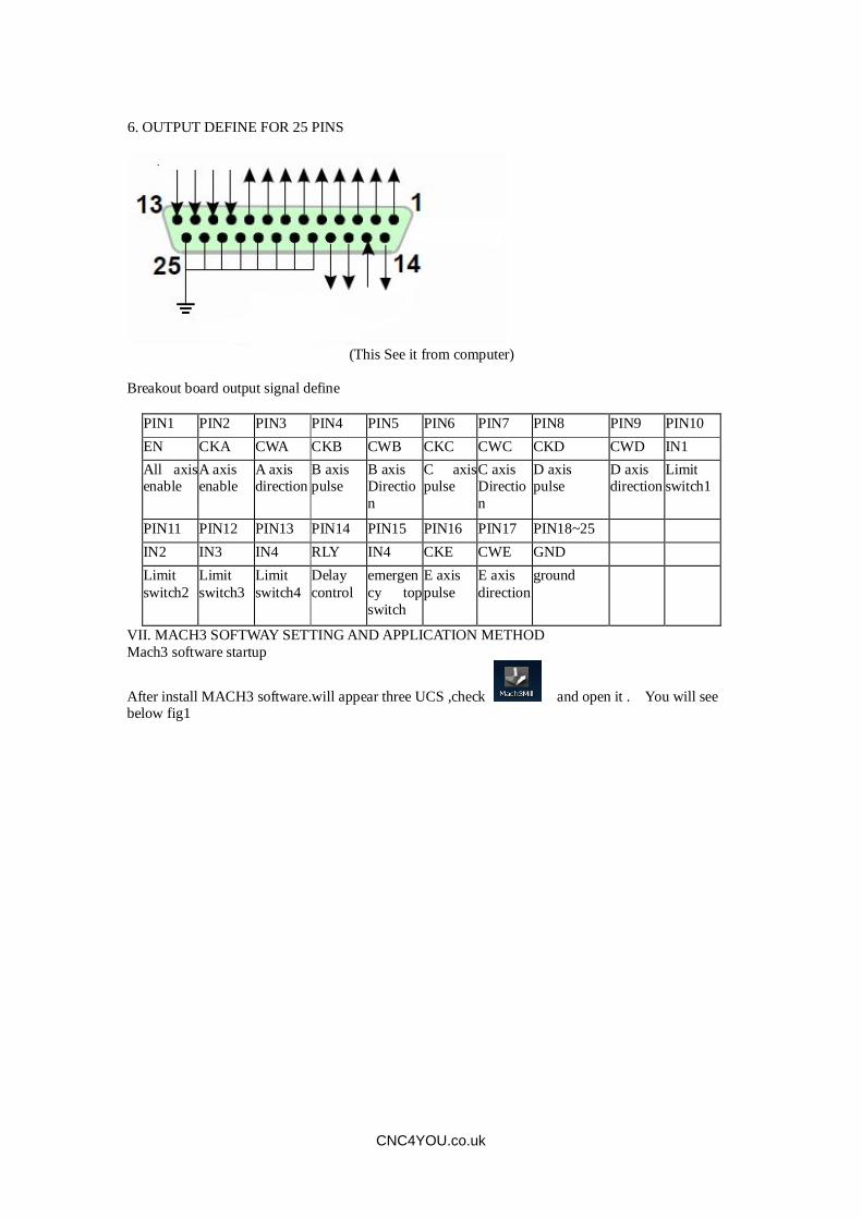
(This See it from computer)
Breakout board output signal define
PIN1 PIN2 PIN3 PIN4 PIN5 PIN6 PIN7 PIN8 PIN9 PIN10 EN CKA CWA CKB CWB CKC CWC CKD CWD IN1 All axis enable
A axis enable
A axis direction
B axis pulse
B axis Direction
C axis pulse
C axis Direction
D axis pulse
D axis direction
Limit switch1
PIN11 PIN12 PIN13 PIN14 PIN15 PIN16 PIN17 PIN18~25 IN2 IN3 IN4 RLY IN4 CKE CWE GND Limit switch2
Limit switch3
Limit switch4
Delay control
emergency top switch
E axis pulse
E axis direction
ground
VII. MACH3 SOFTWAY SETTING AND APPLICATION METHOD Mach3 software startup
After install MACH3 software.will appear three UCS ,check and open it . You will see below fig1
CNC4YOU.co.uk
6. OUTPUT DEFINE FOR 25 PINS
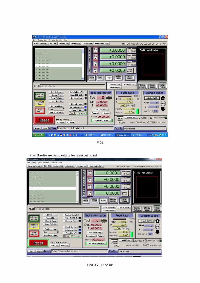
FIG1
Mach3 software Basic setting for breakout board
CNC4YOU.co.uk

FIG 2 Opens under config menu PORT the &PINS menu see fig3
FIG3
See below circuit1 .setting basic frequency ,it effect motor¡s speed, for stepper motor ,usually our setting 25000hz, see fig4
Fig 4
CNC4YOU.co.uk

After setting circuit2 (see fig4),will appear below . we will setting direction and pulse see fig5
Fig5
After setting direction and pulse, check¡output signals¡ , setting delay control see fig6
Fig6
c.Mach3 software Basic setting for limit switch check¡ input signals¡ setting as below: see fig7
CNC4YOU.co.uk

Fig7
emergency stop switch setting : meet urgent things .need emergency stop.we are make pin13 as emergency stop signal input . setting as fig8
FIG8
e.G code run method see fig9,check and run G code menu
CNC4YOU.co.uk

Fig9
Find the G code that of you need run . then open it . see fig10
CNC4YOU.co.uk

CNC4YOU.co.uk
After open the G code, you will see red RESET Button flashing on the screenPress reset using your mouse when steady state you are ready to start, if this is yourfirst cut please set Z Axis well above your work piece and when you start cutting youwill be what we term cutting air and gives you time to switch off if there is a problem.Press green Cycle Start to test your configuration, see fig11

Fig11
If you need handle controller, you can check the ¡TAB¡ on keypad ,can open it .see fig12
FIG12
CNC4YOU.co.uk
Related Documents